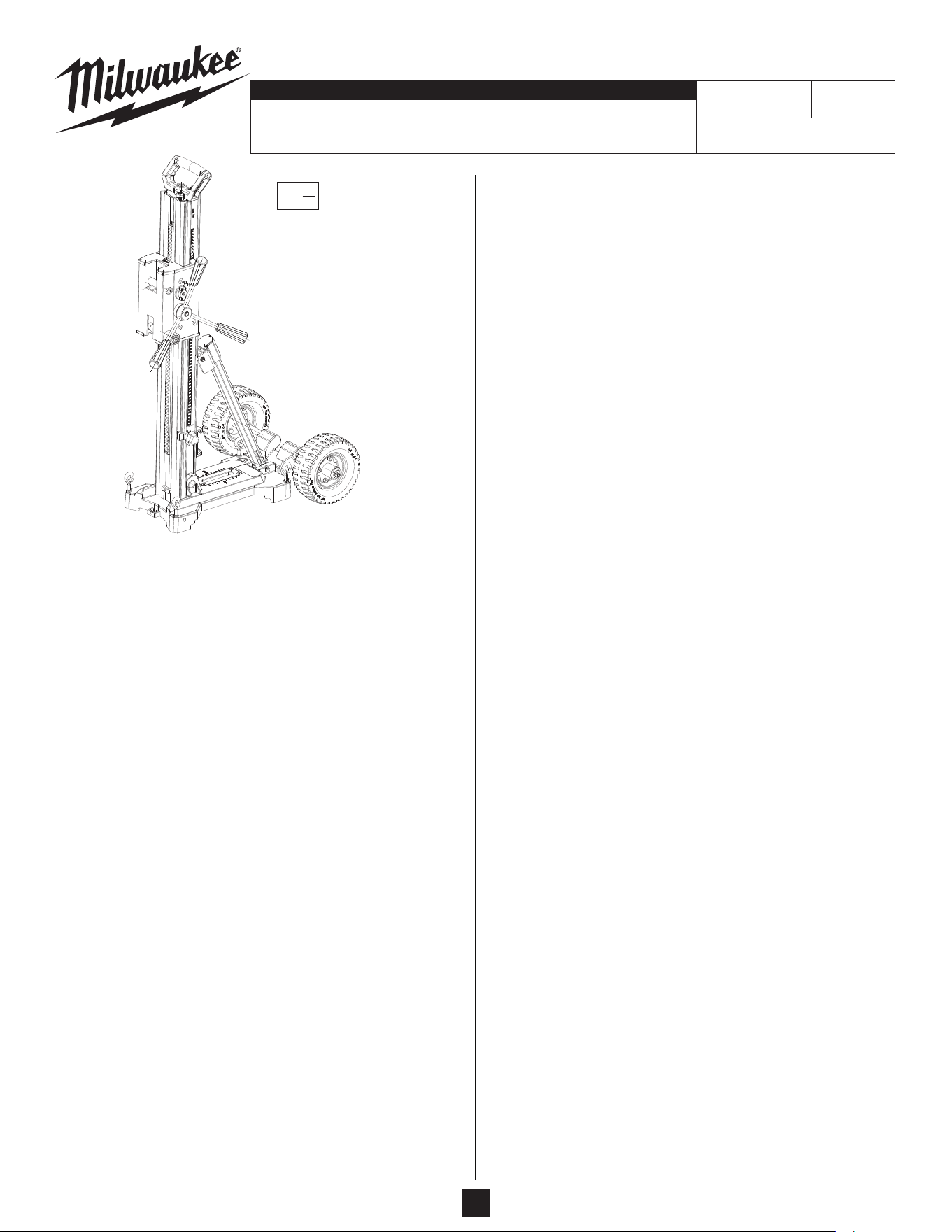
SERVICE PARTS LIST
BULLETIN NO.
Nov. 2023
WIRING INSTRUCTION
DATEREVISED BULLETIN
54-46-0015
Core Rig STAND
SPECIFY CATALOG NO. AND SERIAL NO. WHEN ORDERING PARTS
3302
CATALOG NO.
FIG. PART NO. DESCRIPTION OF PART NO. REQ.
1 05-81-0015 M3x8.5mm Pan Hd. Torx T-10 Screw (23)
2 --------------- Carrier Cap (2)
3 06-83-0014 Set Screw M5 (8)
4 44-60-7105 Hook Tube Pin (1)
5 42-68-5345 Carrier (1)
6 --------------- Threaded Insert (1)
7 --------------- Square Drive Lock Pin (1)
8 --------------- Retaining Collar (1)
9a --------------- Thread Nut (4)
9b --------------- Eccentric Shaft (4)
9c --------------- Ball Bearing (16)
9d --------------- Carrier Wheel (8)
9e --------------- Bushing (8)
9f --------------- Concentric Shaft (4)
10a 05-74-0078 M4x12mm Torx T-20 Screw (2)
10b --------------- Lock Handle (2)
10c --------------- .7 Wire Diameter Spring (4)
10d --------------- Steel Ball .5mm (4)
10e --------------- Nut with Shoulder (2)
10f --------------- Lock Shaft End (1)
10g --------------- Cam Lock Shaft (1)
11a 05-88-0052 SQ Bolt (1)
11b --------------- Handle SQ Drive (1)
11c --------------- Large Bushing (2)
11d --------------- Wear Plate (1)
11e --------------- Washer (2)
11f --------------- Disc Spring (5)
11g --------------- Rack Pinion with Spacer (1)
11h --------------- Pinion Drive Shaft (1)
12a --------------- Lock Cam Holder (1)
12b --------------- Lock Cam (1)
12c --------------- Carrier Lock Spring (2)
12d --------------- Cover Plate (1)
12e --------------- M4x0.7mm Flat Hd. Torx T-20 Screw (2)
13a 43-98-7125 Feed Handle Knob (3)
13b 43-98-7130 Feed Handle Post (3)
13c --------------- Hub (1)
13d --------------- Square Drive Assembly (1)
14 --------------- Jacking Screw Cap (1)
15 --------------- Jacking Screw M14 (1)
16 28-44-0150 Mast Handle (1)
17 44-72-0125 Pointer (1)
18 --------------- Mast Cap (1)
19 43-24-2835 Mast Extrusion (1)
20 --------------- Rack Top Plate (1)
21 06-82-0058 M5x0.8mm Pan Hd. T-25 M Screw (2)
22 --------------- Mast Rack (1)
23 --------------- Rack Bottom Plate (1)
N40A
24 --------------- Pin (3)
25 --------------- Stopper (1)
26 43-98-7085 Depth Adjust (1)
27 45-04-7030 Depth Indicator Set Screw Knob (1)
28 --------------- Mast Vial Holder (1)
29 --------------- Vial (1)
30 --------------- Battery Holder (1)
31 05-80-0011 M6x1mm FH Hexagon Recess M Screw (2)
32 45-88-0069 Flat Washer (1)
33 06-14-0370 Machining Bolt (1)
34 --------------- Mast Sleeve (1)
35 06-83-7040 Angle Brace (1)
36 31-83-0240 Mast Clamp Blot Tube Spacer (1)
37 --------------- Bushing (1)
38 --------------- Angle Adjustment Slider (1)
39 --------------- Angle Brace Cap (1)
40 --------------- Bevel Adjust Plate (1)
41 42-70-5268 E-Ring (1)
42 43-24-2840 Angle Brace Extrusion (1)
43 --------------- Angle Adjust Plate (1)
44 --------------- Washer (1)
45 06-82-0073 M6x1mm Pan Hd. Torx T-30 M Screw (1)
46 34-60-0026 Snap Ring (2)
47 --------------- 13MM Connection Pin (1)
48 --------------- Eye Bolt (4)
49 05-80-0012 M6x1mm FH Hexagon Recess M Screw (4)
50 --------------- Flat Plate (1)
51 42-04-3775 Base Adaptor (1)
52 --------------- Vial for Core Drill Stand (1)
53 --------------- Bevel Retaining Ring MT-36 (1)
54 --------------- Sleeve Screw M10 (4)
55 --------------- Round Leveling Pad (4)
56 --------------- Flat Washer 4.1x10x1 (4)
57 --------------- M4x14mm Pan Hd. Torx T-20 M Screw (4)
58 40-50-9227 Spring Plunger (1)
59 --------------- Stamping, Washer (2)
60 --------------- Wheel Mount and Shaft Assembly (1)
61 43-98-7135 Knob Screw (1)
62 45-94-8470 Stand Wheel (2)
63 --------------- Washer (2)
64 --------------- Flange Bolt M8x25 (2)
70 14-34-7080 Carrier Cap Kit (2)
71 14-46-9880 Lock Cam Kit (1)
72 14-73-3220 Lock Shaft Kit (1)
73 14-34-7085 Lock Knob Kit (2)
74 14-48-0365 Lock Kit (1)
75 14-29-9050 Pinion Shaft Kit (1)
76 14-46-9885 Feed Handle Kit (1)
77 14-46-9890 Feed Handle Hub Assembly (1)
78 45-04-7020 Jack Screw Assembly (1)
79 14-73-3250 Mast Cap Kit (1)
80 44-80-0225 Mast Rack Kit (1)
81 43-46-0185 Depth Gauge Kit (1)
82 44-08-0220 Vial Assembly (1)
83 42-70-5720 Battery Clip Kit (1)
84 45-16-3255 Mast Tightness Kit (1)
85 45-16-3220 Mast Pivot Kit (1)
86 44-08-0225 Base Vial Kit (1)
87 44-66-7290 Anchor Slot Plate Kit (1)
88 45-16-3230 Angle Brace Cap Kit (1)
89 45-16-3225 Angle Brace Pivot Kit (1)
90 14-46-9910 Wheel Assembly Kit (1)
91 14-46-9950 Wheel Assembly Fasteners Kit (1)
92 14-46-9920 Adjustable Wheel Kit (4)
93 14-46-9925 None Adjustable Wheel Kit (4)
94 14-34-7065 Leveling Bolt Kit (4)
95 14-34-7060 Leveling Bolt Feet Kit (4)
96 14-34-7090 Angle Adjustment Kit (1)
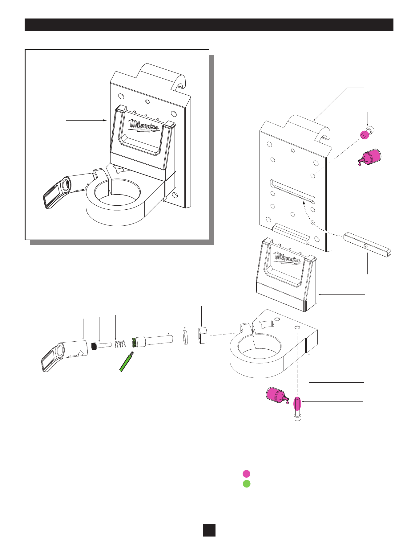
97 3314* Vacuum Pad Accessory (1)
98 3315** Handheld Drill Mounting Plate (1)
100 12-20-9846 Service Nameplate (Not Shown) (1)
MILWAUKEE TOOL
l
www.milwaukeetool.com
13135 W. LISBON RD., BROOKFIELD, WI 53005
Drwg. 1
EXAMPLE:
Component Parts
(Small #) Are Included
When Ordering The
Assembly (Large #).
00
0
SERIAL NO.
* For more information on product #3314, refer to SPL #54-46-0020
** For more information on product #3315, refer to page 4
FIG. PART NO. DESCRIPTION OF PART NO. REQ.
1
9b
(x4)
29e
(x8)
9d
(x8)
9c
(
x16
)
9a
(x4)
1
(x8)
5
3
(x2)
4
2
3
(x4)
1
(x8)
9f
(x4)
10b
(x2)
10a
(x2)
10f
11c
10c
(x4)
10d
(x4)
10e
(x2)
11a
11b
11d
12b
12c
(x2)
12a
12d
12e
(x2)
11c
11e
(x2)
11f
(x5)
11g
11h
6
7
8
10g
13a
(x3)
13b
(x3)
13c
13d
70
1
2
71
12a 12b 12c
12d 12e
92
9a 9b 9c
9d 9e
3 9c
9d 9e
9f
72
10a 10b
10c 10d
10e 10f
10g
93
75
11a 11b
11c 11d
11e 11f
11g 11h
74
3 6
7 8
77
13c 13d
76
13a 13b
13c 13d
73
10a 10b
10c 10d
97
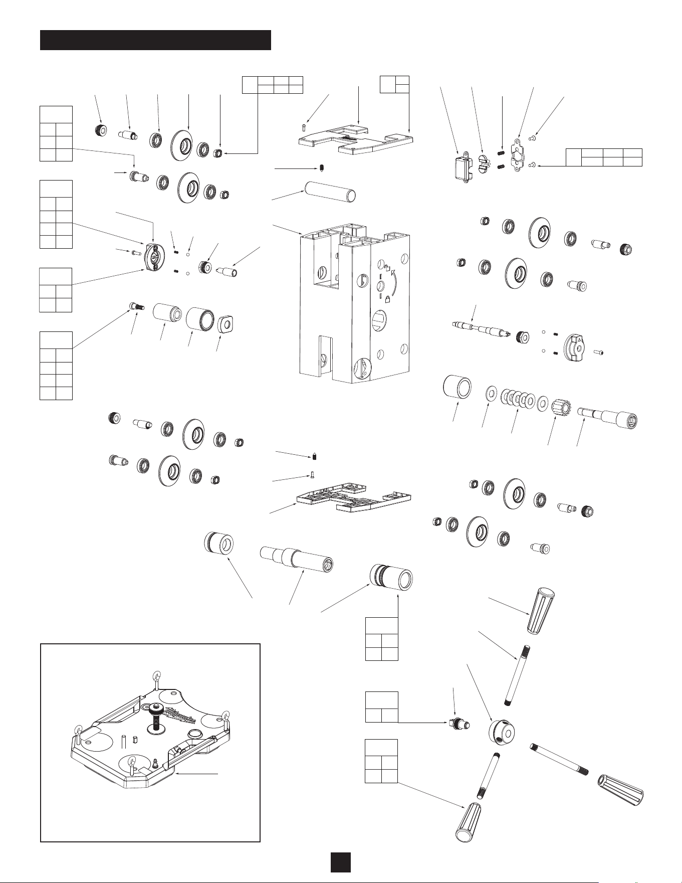
TOOL ASSEMBLY - EXPLODED VIEW
* For more information on product #3314,
the Vacuum Pad Accessory, refer to SPL
#54-46-0020
2
14
15
16
1
(x4)
20
21
(x2)
22
24
(x2)
25
23
17
18
19
26
27
24
28
29
30
31
(x2)
32
33
34
3
(x2)
48
(x4)
49
(x4)
50
51
52
53
54
(x4)
55
(x4)
58
57
(x4)
64
(x2)
63
(x2)
62
(x2)
61
60
59
(x2)
43
47
46
36
35
37
1
(x3)
39
40
42
38
44
45
46
41
56
(x4)
14 15
78
1 18
79
26 27
81
30 31
83
3 34
85
20 21
22 23
24
80
28 29
82
24 25
32 33
84
52 53
86
49 50
87
1 39
88
43 44
45 46
47
89
59 60
61 62
63 64
90
59 63
64
91
48 54
55 56
57
94
55 56
57
95
24 35
36 37
38 40
41
96
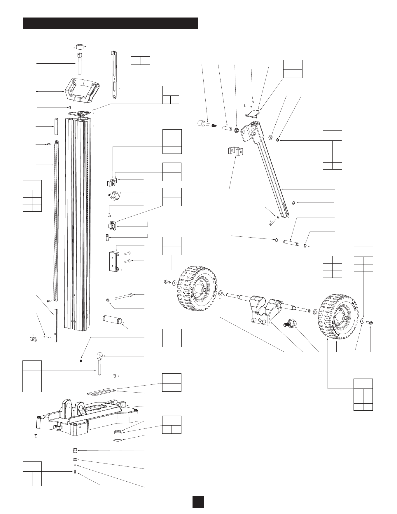
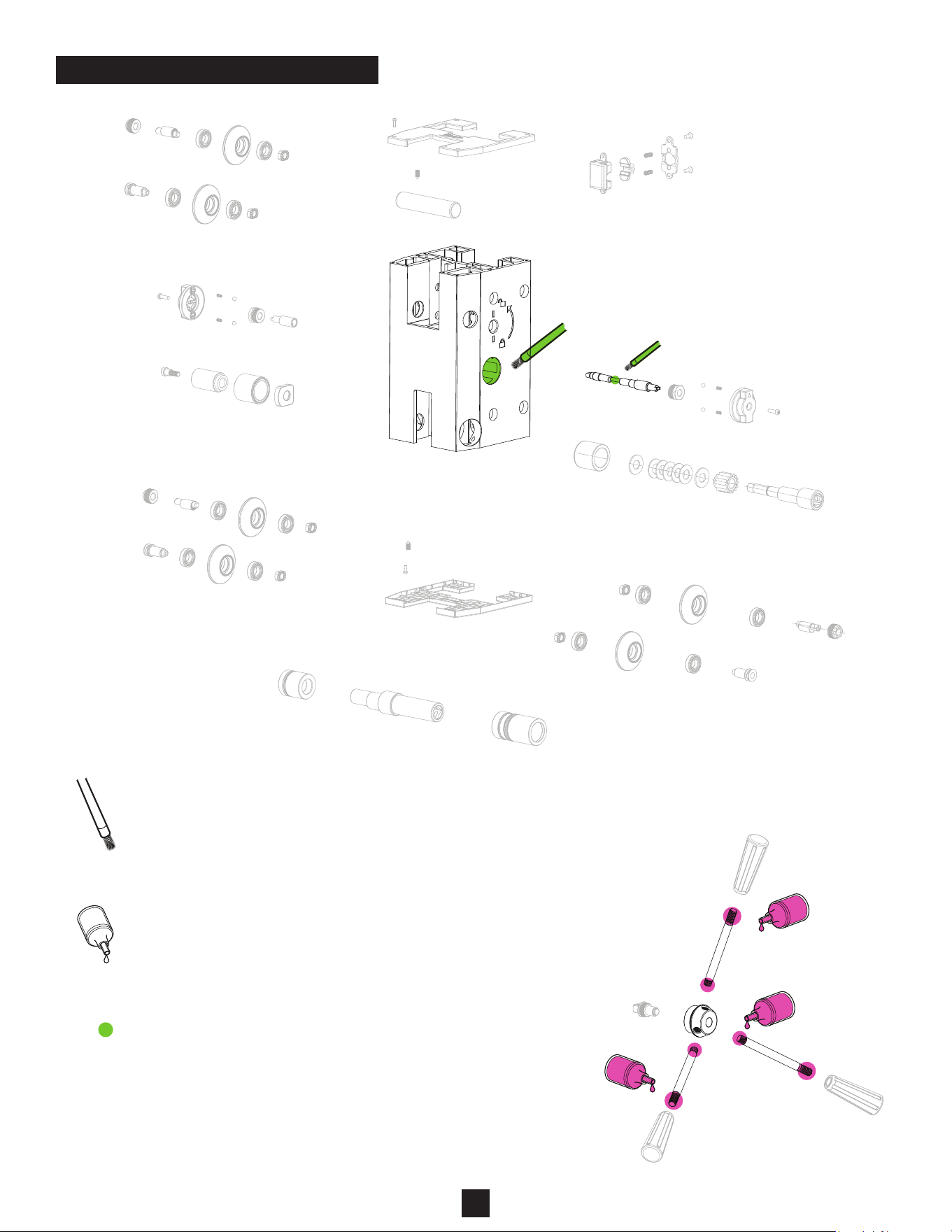
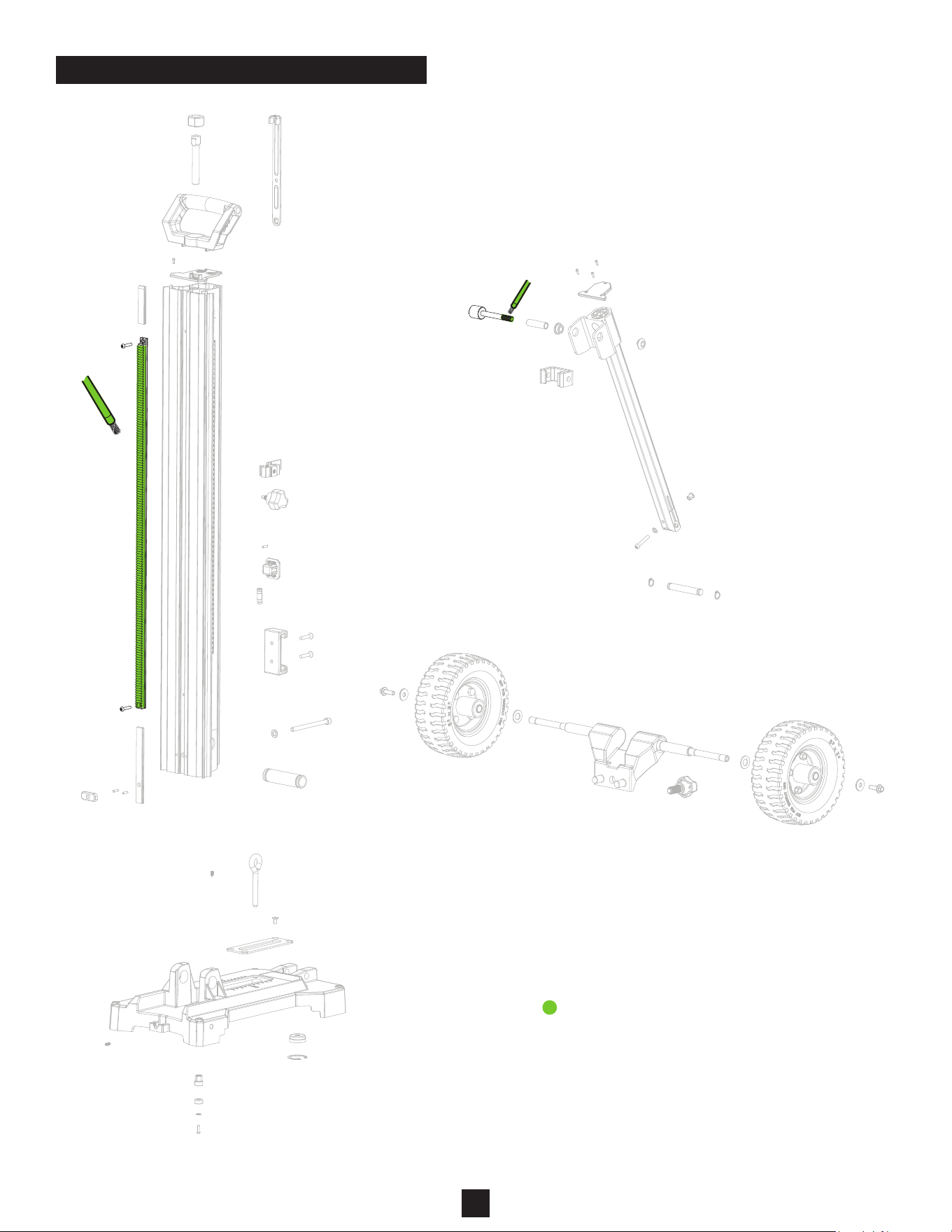
TOOL ASSEMBLY - EXPLODED VIEW (Continued)
3
Apply a drop of
Red Loctite 263
to the threads of
each screw prior
to installation
®
LUBRICATION
= 263 Red Loctite
®
= Type ‘J’ Grease, No. 49-08-4220
NOTE: When servicing, remove 90-95% of the
existing grease prior to installing Type ‘J’. Original
grease may be similar in color but not compatible
with ‘J’. Clean gear assemblies with a clean dry cloth.
Apply a drop of
Red Loctite
263
to the threads of
each screw prior
to installation
®
1
6
5
4
3
2
9
10
(x7)
12
13
(x2)
7
8
3315 - HANDHELD DRILL MOUNTING PLATE ACCESSORY
FIG. PART NO. DESCRIPTION OF PART NO. REQ.
1 44-10-0017 Tool Free Handle (1)
2 05-89-0013 Tool Free Handle Bolt (1)
3 40-50-0083 Tool Free Spring (1)
4 05-89-0014 Tool Mount Screw Bolt (1)
5 45-88-0068 Washer (1)
6 06-55-0015 Tool Free Handle Holder (1)
7 43-96-0011 Flange Key (1)
8 --------------- Logo Flange (1)
9 --------------- Carrier Mount (1)
10 45-04-1090 M6 x 16mm M Screw (7)
12 --------------- Tool Mount Plate (1)
13 05-88-0051 M6 x 30mm Socket Head Cap Screw (2)
98 3315 Handheld Drill Mounting Plate Accessory (1)
4
98
LUBRICATION NOTES:
Type ‘J’ Grease
No. 49-08-4220, 1 lb. can
NOTE: When servicing, remove 90-95% of existing grease
prior to installing Type ‘J’. Original grease may be similar in
color but may not compatible with ‘J’. Prior to reinstalling,
clean gear assemblies with a clean, dry cloth. Lightly coat
all parts highlighted here with ‘J’ grease. Apply a greater
amount of grease to all internal and external gear teeth.
NOTE
Regarding parts to receive thread locking sealant:
Place one to two drops of the recommended Loctite® thread locking
sealent (or the equivelant) to the threads of parts shown prior to
installation.
NOTE
Regarding parts to be lubricated:
Apply a light coating of grease to
all highlighted parts shown prior to installation.
Reference the key below for grease types.
Add .1ML of
LOCTITE 263
to each part #13b -
Feed Handle Post
Add 1.5 +/- 0.1G
of "J" Grease
to part #11d -
Wear Plate
Add 0.1G of "J" Grease
to part #10g - Cam Lock
Shaft
LUBRICATION INSTRUCTIONS
5
LUBRICATION NOTES:
Type ‘J’ Grease
No. 49-08-4220, 1 lb. can
NOTE: When servicing, remove 90-95% of existing grease
prior to installing Type ‘J’. Original grease may be similar in
color but may not compatible with ‘J’. Prior to reinstalling,
clean gear assemblies with a clean, dry cloth. Lightly coat
all parts highlighted here with ‘J’ grease. Apply a greater
amount of grease to all internal and external gear teeth.
Add 6G of
"J" Grease
to part #22
Mast Rack
Add .1G of
"J" Grease
to part #35
Angle Brace
LUBRICATION INSTRUCTIONS (Continued)
6

SCREW TORQUE SPECIFICATIONS
SEAT TORQUE
FIG. PART NO. DESCRIPTION OF FASTENER WHERE USED (kgf-cm) (lb-in)
1 --------------- M3 x 8.5mm Pan Hd. Torx T-10 Screw Carrier Cap 4±0.4 3±.3
3 --------------- M5 Set Screw Wheel and Mast Pivot 20±2 17±1.7
9a --------------- Thread Nut Adjustable Wheel 143±21 124±18
9b --------------- Eccentric Shaft Adjustable Wheel 15±1.5 13±1.3
10a --------------- M4 x 12mm Pan Hd. Torx T-20 Screw Lock Knob and Shaft 15±1.5 13±1.3
10e --------------- Nut with Shoulder Lock Shaft 100±15 86±13
11a --------------- Square Bolt Pinion Shaft 120±18 104±15
12e --------------- M4 x .7 Pan Hd. Torx T-20 Screw Lock Cam 20±2 17±1.7
15 --------------- Jacking Screw M14 x 1 Jack Screw Assembly 50±7.5 43±6.5
21 --------------- M5 x .8 Pan Hd. Torx T-25 Screw Mast Rack 50±7.5 43±6.5
31 --------------- M6 x 1 Flat Hd. Hexagon Recess Screw Battery Clip 50±7.5 43±6.5
33 --------------- Machining Bolt Mast 100±15 86±13
45 --------------- M6 x 1 Pan Hd. Torx T-30 Screw Angle Brace Pivot 80±12 69±10
49 --------------- M6 x 1 Flat Hd. Hexagon Recess Screw Anchor Slot 25±4 21±3.4
57 --------------- M4 x 14mm Pan Hd. Torx T-20 Screw Leveling Bolt 20±2 17±1.7
64 --------------- M8 x 25 Flange Bolt Wheel Assembly 100±15 86±13
7