USER
GUIDE
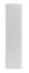
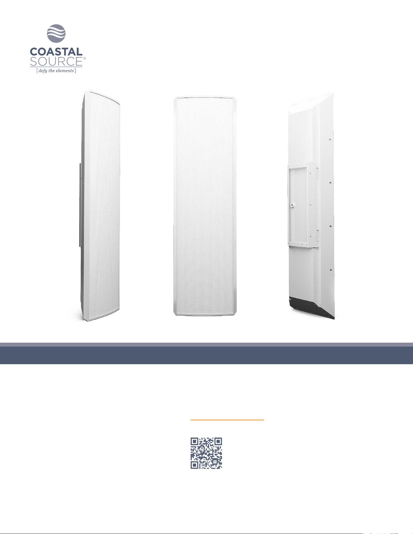
300 SERIES RAZOR SPEAKERS
Scan for Specications
Keep this manual for future reference © 2024 Coastal Source

300 Series Razor Speaker User Guide | coastalsource.com 1
FEATURES & BENEFITS
• Custom-designed, engineered, and optimized ultra-shallow drivers to provide impressive performance from a slim enclosure.
• The Acoustic Fractal Waveguide™ tweeter bridge dramatically improves clarity and efciency.
• Installation exibility in many forms for wall mounted, corner mounted, and ground mounted applications.
• High quality materials and construction built to Defy the Elements.™
• Built to be part of a complete patented Coastal Source Plug+Play™ system or can be easily integrated into existing systems.
300 SERIES RAZOR SPEAKERS
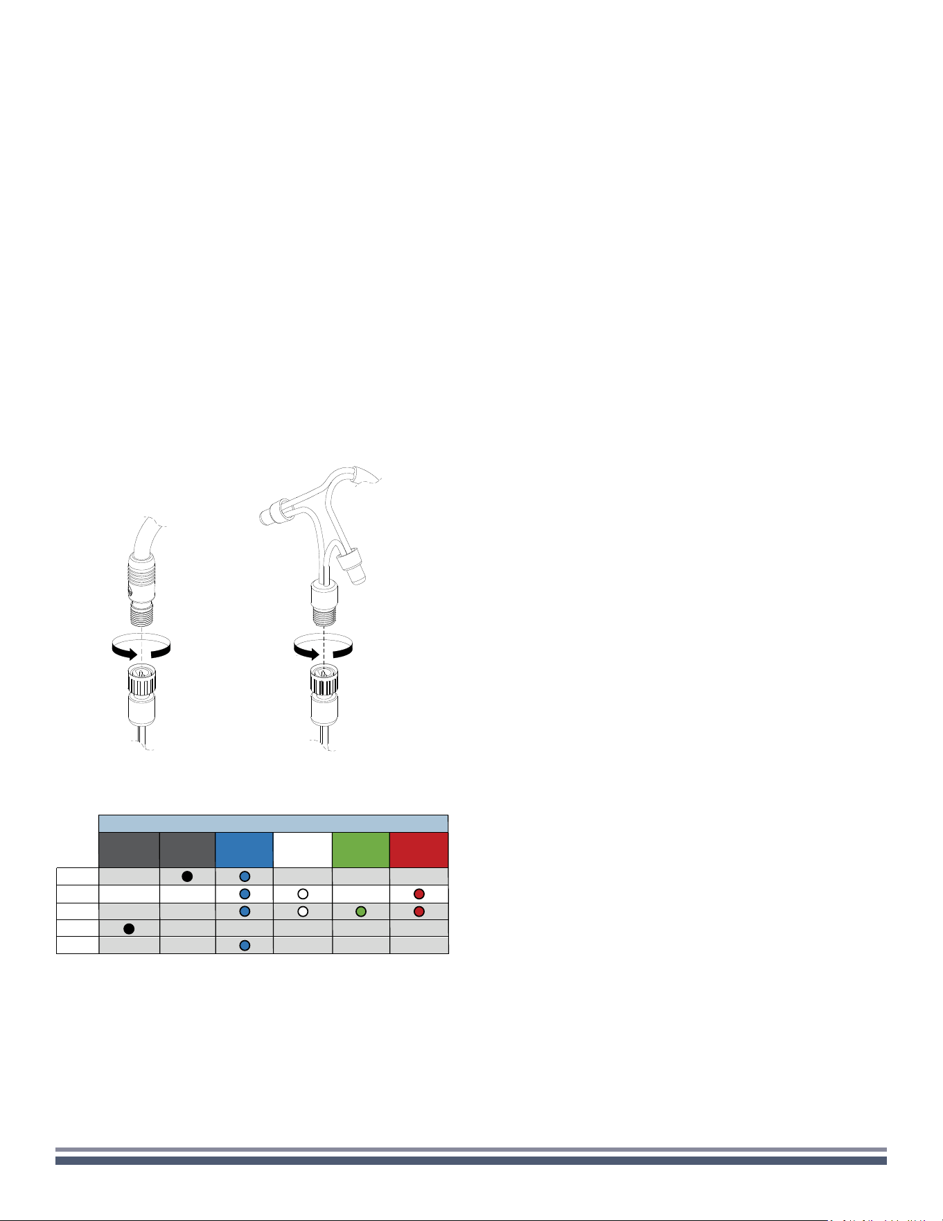
WIRING INSTALLATION
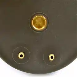
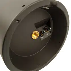
All Coastal Source speakers feature our patented Coastal
Connector for a waterproof direct burial connection
(see Figure 1). For connecting to a Coastal Source amplier just
select the appropriate cable lengths and y-cables and Plug+Play™
the speakers to the amplier. For connection to 3rd party (non-
CS) ampliers, Coastal Source pigtail cables are included to
convert the Coastal Mini Connector™ on the speaker to a typical
2 conductor bare wire that can be spliced in to a conventionally
wired system (see Figure 2).
SOUND TUNING
Note that optimal sound tuning is subjective and specic to each
listener so there are no hard and fast rules for optimizing the
sound of a Coastal Source system. We have designed our systems
with exibility to allow you to shape the sound to your personal
preferences. The following information is offered as a brief guide.
It is highly recommended to take the time to experiment and tune
the system to achieve your desired sound.
NOTE: Coastal Source outdoor audio systems are the clearest
and most efcient on the market, but they are not designed to
run at 100% volume full-time. If the system is going to be played
at loud volumes for an extended period of time, Coastal Source
recommends setting the volume to 75-80%.
Speaker Placement
Mounted at on a wall surface
Large and open sound stage with a clean and fuller frequency
balance.
Mounted in a corner
Medium sound stage with a heavier bass balance.
SETUP & INSTALLTION GUIDELINES
Spacing Guidelines
Maximum distance between speakers: 40’
Minimum distance between speakers: 12’
Speaker Coverage Guidelines
Each Razor speaker can cover 50-500 sqft of
listening space.
Creating Listening Areas
For larger listening areas, surround the area with speakers
equidistant from the prime listening position, crisscrossing or
alternating the left and right channels.
For smaller listening areas, simply aim speakers in toward the
listening positions.
SAT SUB LEFT CENTER RIGHT
RAZOR INPUT COLOR CODING - 300 SERIES
SAT SUB LEFT CENTER RIGHT
RZ310
RZ330
RZ340
RZ350
RZ320
FULL
RANGE
Figure 1 (CMC P+P) Figure 2 (spliced)
300 Series Razor Speaker User Guide | coastalsource.com 2
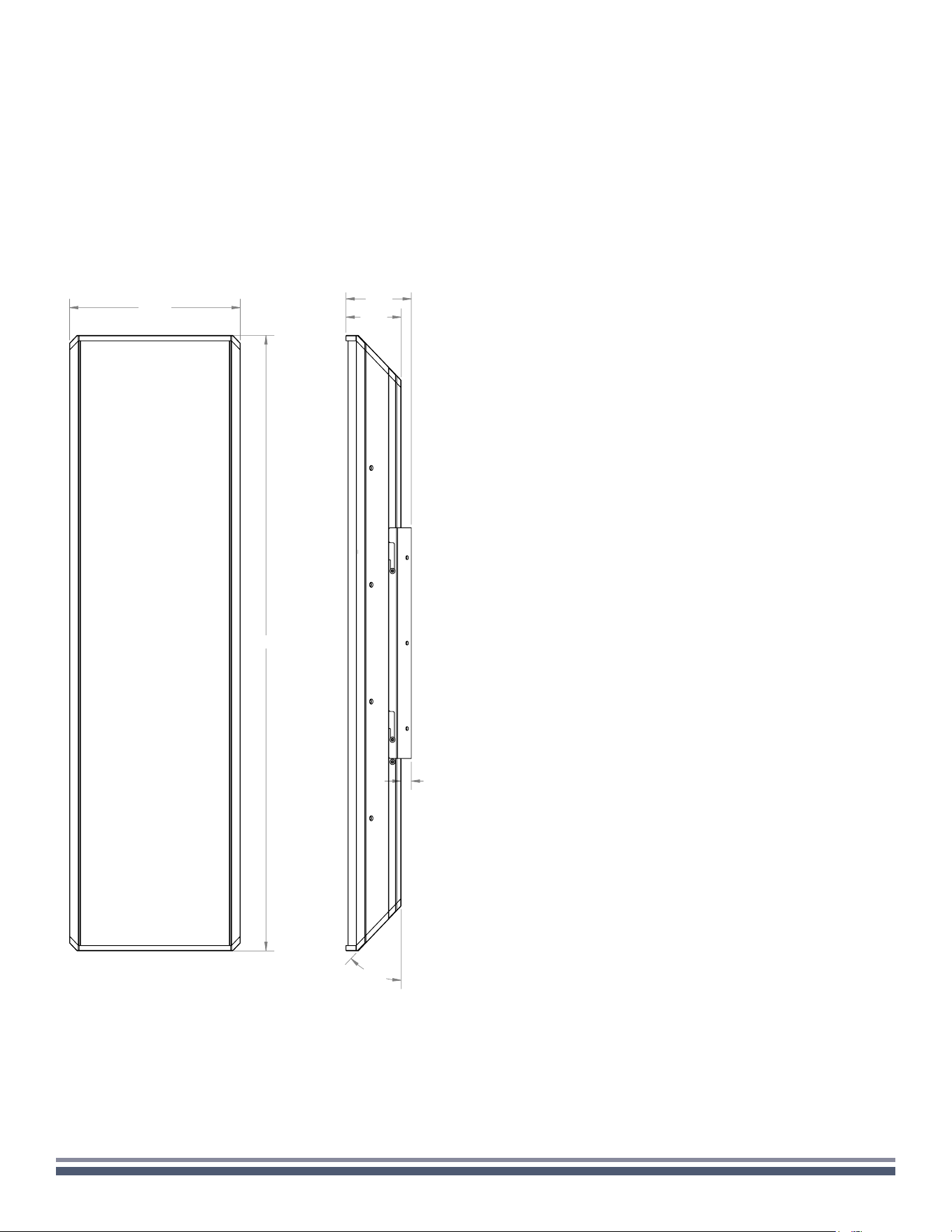
SPECIFICATIONS
RZ300 SERIES SPECIFICATIONS
Size (H x W x D): 36in x 10.5in x 3.38in
Size with bracket (H x W x D): 36in x 10.5in x 4in
Construction: Aluminum extrusion, Aluminum wall bracket,
Kydex composite grille
Finish: White or Black Powder Coat
Mounting: Corner, Surface
RZ310 HIGH POWER 3-WAY RAZOR SPEAKER
Weight: 30.6 lbs.
Driver Complement: 5.25” coaxial, 4x 5.25” LF Woofers
Power Handling: 75W SAT / 400W SUB
Frequency Response: 100Hz-20kHz SAT, 40-100Hz SUB
(@-6dB with EQ present)
Sensitivity: 88dB SAT / 86dB SUB (1W/1m)
Dispersion: 110˚ conical (@-6dB)
Impedance: 8 ohms SAT, 8 ohms SUB
Speaker Connector: 2x CMC Male Pigtails (bi-amplied)
RZ320 RAZOR 2.1 SOUNDBAR
Weight: 26.6 lbs.
Driver Complement: 2x 5.25” coaxial, 3x 5.25” LF woofers
Power Handling: 75W SAT (x2) / 300W SUB
Frequency Response: 100Hz-20kHz SAT, 40-100Hz SUB
(@-6dB with EQ present)
Sensitivity: 88dB SAT / 85dB SUB (1W/1m)
Dispersion: 110˚ conical (@-6dB)
Impedance: 8 ohms SAT, 8 ohms SUB
Speaker Connector: 3x CMC Male Pigtails (tri-amplied
RZ330 RAZOR LCR SOUNDBAR
Weight: 31.4 lbs.
Driver Complement: 3x 5.25”coaxial, 2x 5.25” LF woofers
Power Handling: 75W SAT (x3) / 200W SUB
Frequency Response: 100Hz-20kHz SAT, 40-100Hz SUB
(@-6dB with EQ present)
Sensitivity: 88dB SAT / 83.5dB SUB (1W/1m)
Dispersion: 110˚ conical (@-6dB)
Impedance: 8 ohms SAT, 8 ohms SUB
Speaker Connector: 4x CMC Male Pigtails (quad-amplied)
RZ340 RAZOR LINE SOURCE SPEAKER
Weight: 33.6 lbs.
Driver Complement: 6 x 5.25” coaxials
Power Handling: 500W
Frequency Response: 100Hz-20kHz (@-6dB with EQ present)
Sensitivity: 93dB (1W/1m)
Dispersion: 100˚ horizontal, 28” high vertical
Impedance: 6-8 ohms
Speaker Connector: CMC Male Pigtail
RZ350 RAZOR SUBWOOFER SPEAKER
Weight: 27.3 lbs.
Driver Complement: 4x 5.25” LF woofers
Power Handling: 400W
Frequency Response: 40Hz - variable, present dependent
(@-6dB with EQ present)
Sensitivity: 86dB (1W/1m)
Dispersion: Omnidirectional-horizontal, 180˚ - vertical
Impedance: 8 ohms
Speaker Connector: CMC Male Pigtail
10.50
36.00
3.38
4.00
0.63
45°
45°
SPECIFICATIONS
U.S. Design Patent: D1,034,528 S
300 Series Razor Speaker User Guide | coastalsource.com 3
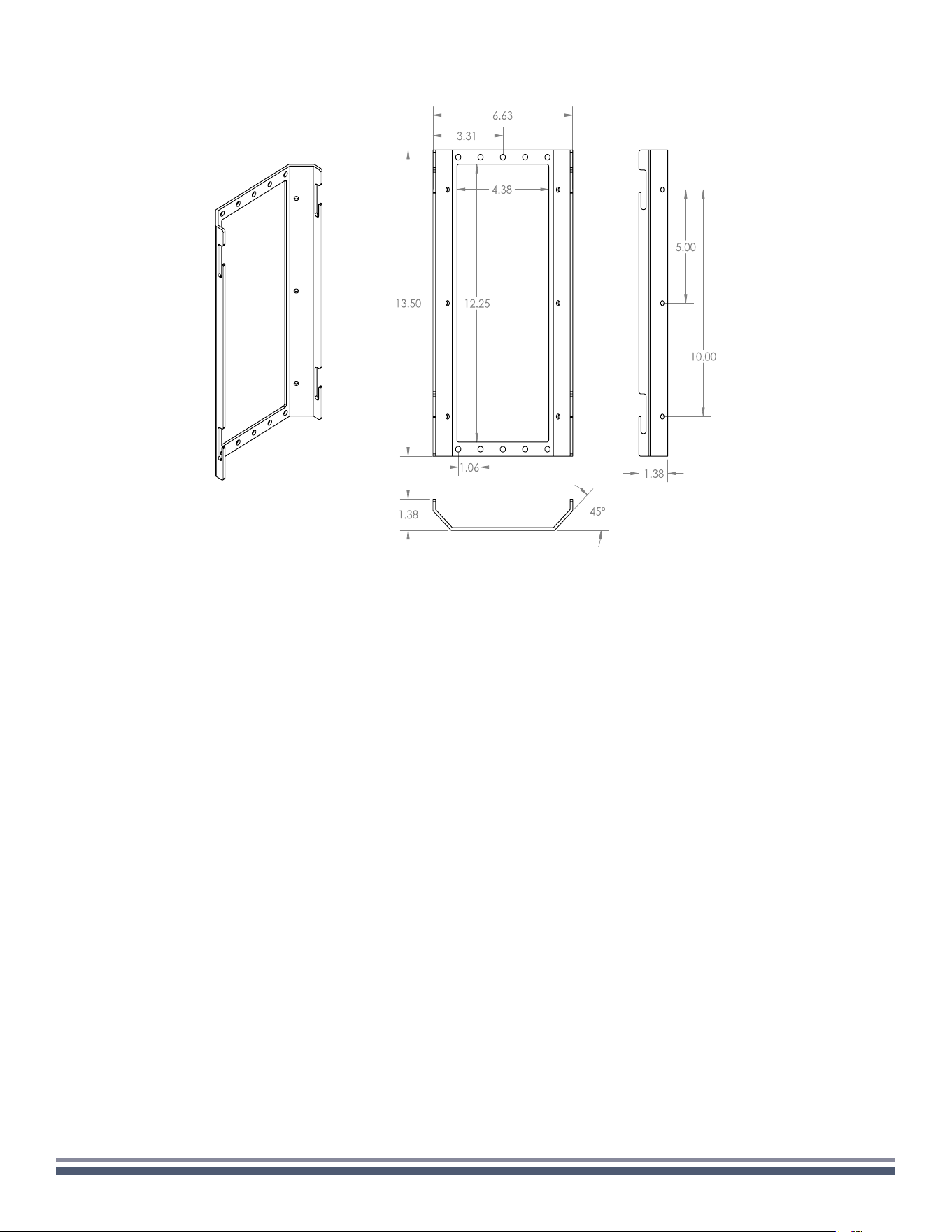
BRACKET DIMENSIONS
WARRANTY INFORMATION
COASTAL SOURCE warrants its goods against defects in material and functionality. At COASTAL SOURCE’s sole discretion, COASTAL
SOURCE will either repair or replace (at no charge) any properly installed and maintained COASTAL SOURCE goods that fail under normal
operating conditions within the specied warranty period noted below. All goods are warranted from the date of invoice, provided they
are returned to the corporate ofce for inspection (transportation prepaid) and determined defective under the terms of the warranty.
This warranty covers only equipment manufactured by COASTAL SOURCE and does not extend to transportation, installation, labor
compensation, or replacement charges, nor does it apply to any equipment of another manufacturer used in conjunction with COASTAL
SOURCE equipment. Our warranty becomes null and void in the event of damage to the product resulting from breakage due to abuse or
misuse; repairs, alterations or modications of the product by anyone other than authorized representatives thereof; damage resulting
from accidents, vandalism, acts of nature, and improper use. See Lifetime Care Program for additional options.
This product bears a ve (5) year limited warranty.*
* All Coastal Source products bear a 2-year limited warranty for commercial/non-residential installations.
Filing a Claim
To le a warranty claim, please contact us to receive a Return Materials Authorization number (RMA) and a return shipping label:
WARRANTY CLAIMS DEPARTMENT
1.800.719.1996
warranty@coastalsource.com
Please include your contact information,
a copy of your receipt and reason for the return.
300 Series Razor Speaker User Guide | coastalsource.com 4
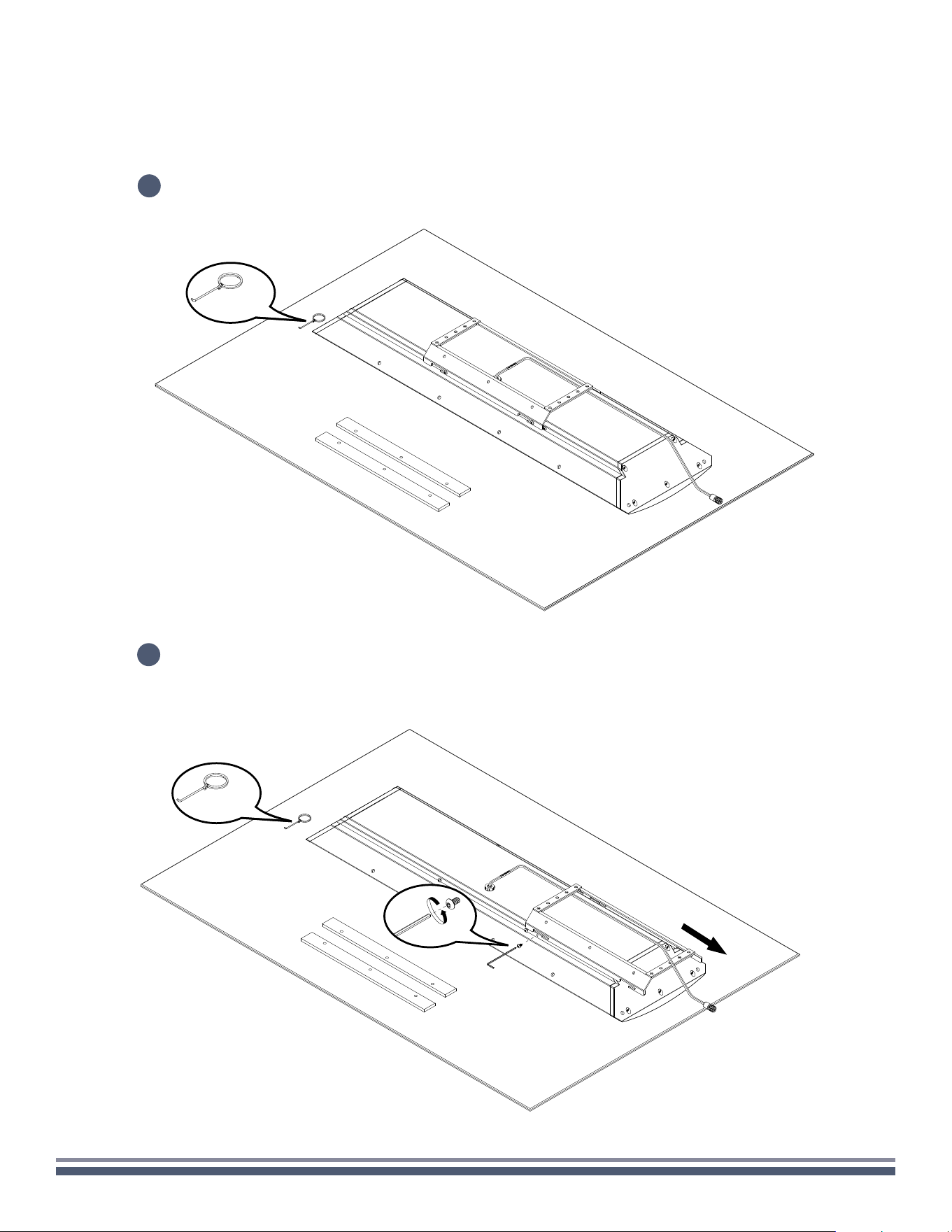
WALL
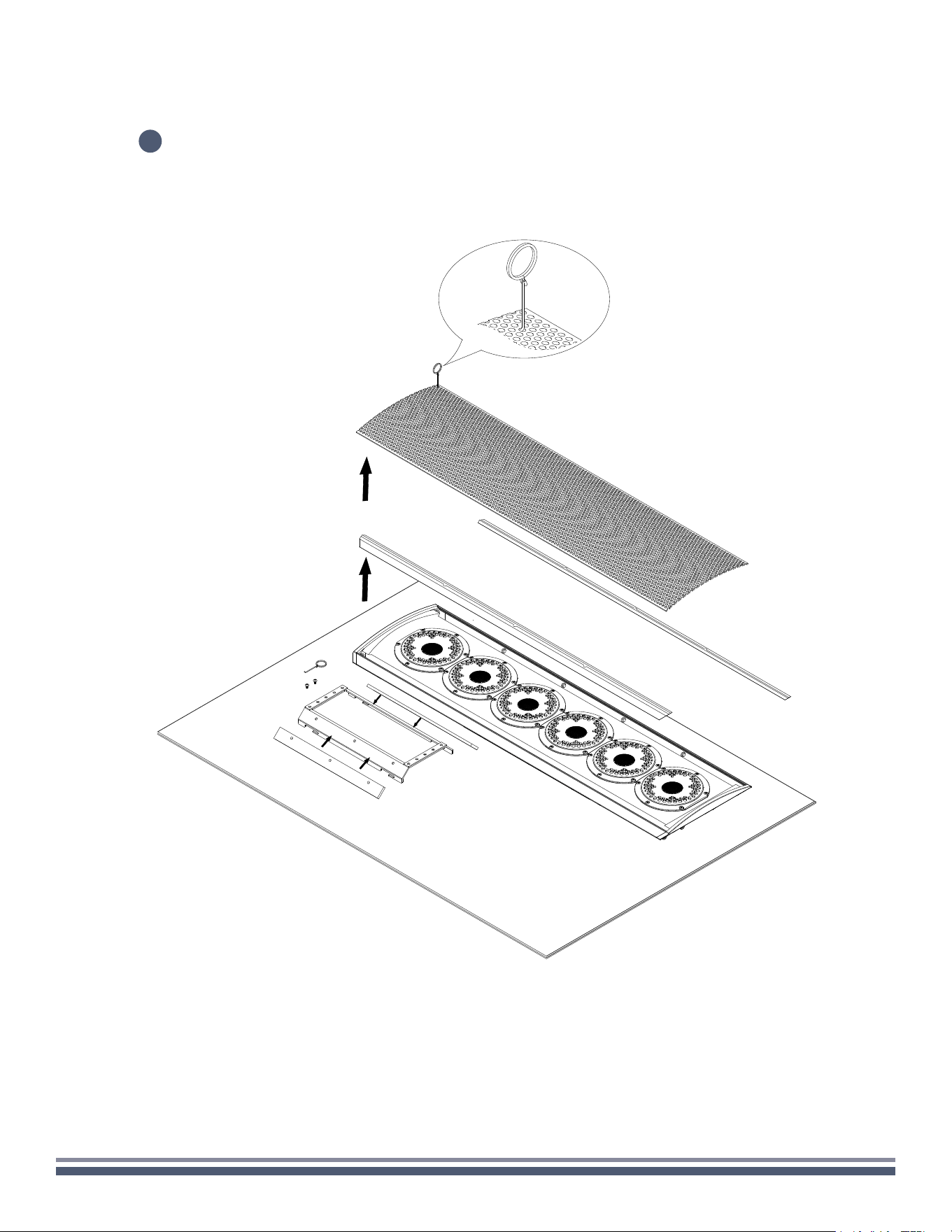
Carefully remove speaker assembly, RingKey, and foam strips from the box, setting
on a soft surface so as not to mar the finish.
1
1x
1x
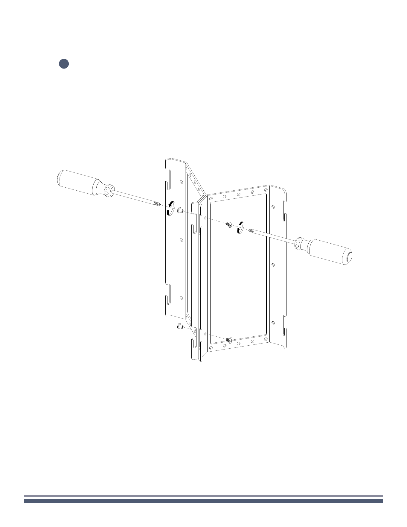
Using a 3/32" Hex Key, remove the two locking screws beneath the attached mounting bracket,
and loosen the four screws attaching the bracket to the speaker so that the bracket moves
freely. Remove the mounting bracket from the speaker.
2
300 Series Razor Speaker User Guide | coastalsource.com 5
WALL
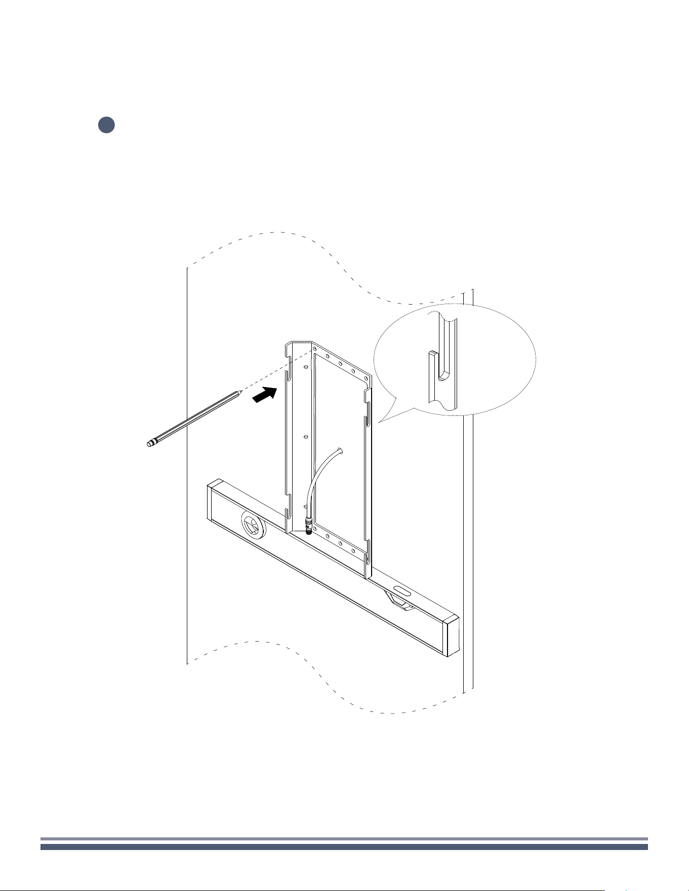
Place the mounting bracket (ensuring slots are facing up) on the wall in the intended mounting location. Be sure that
the speaker wire penetration point is somewhat centered in the bracket. With the help of a level, mark at least four
holes on the wall through the holes of the bracket.
3
300 Series Razor Speaker User Guide | coastalsource.com 6
WALL
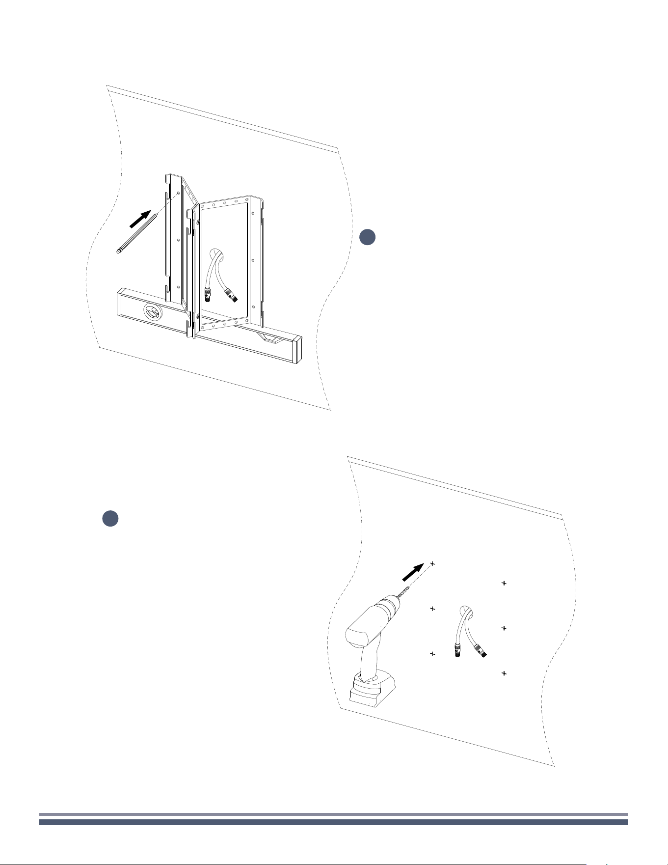
4
5
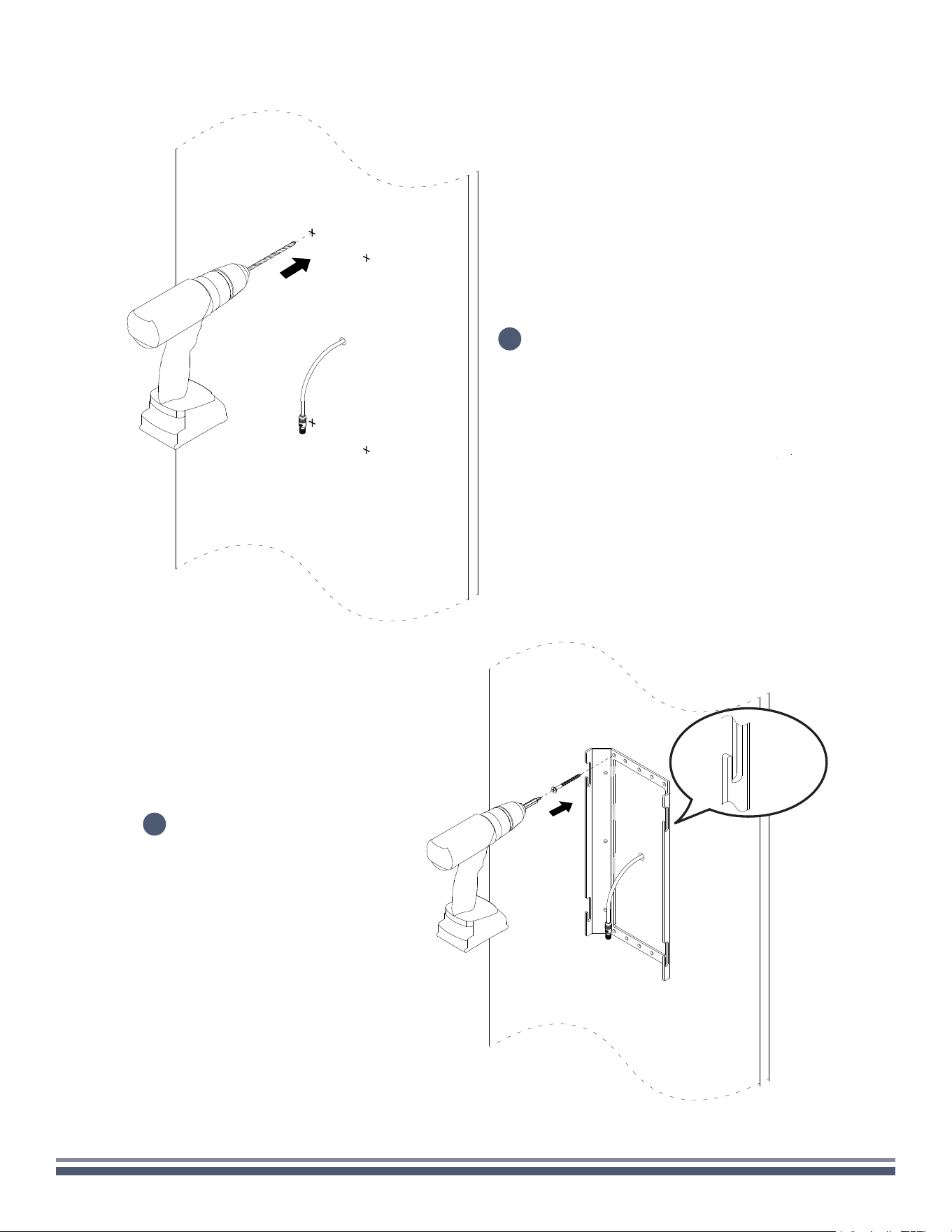
Remove the bracket and drill the appropriate sized
pilot holes for your intended fasteners at the
marked location to prepare for final mounting.
Again ensuring that slots are facing up,
place mounting bracket back against
the wall in the intended location. Using
the appropriate fasteners, secure the
mount to the wall.
300 Series Razor Speaker User Guide | coastalsource.com 7
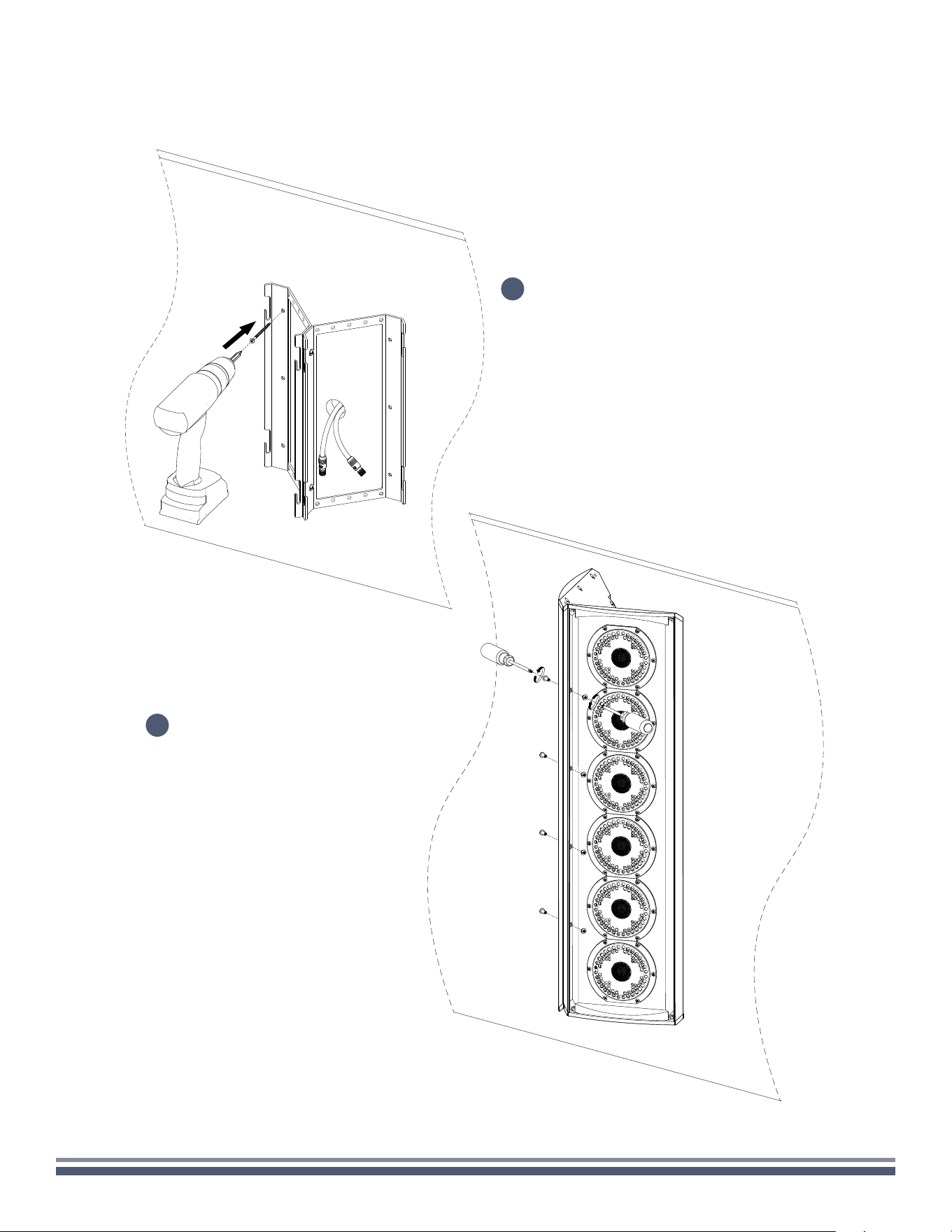
WALL
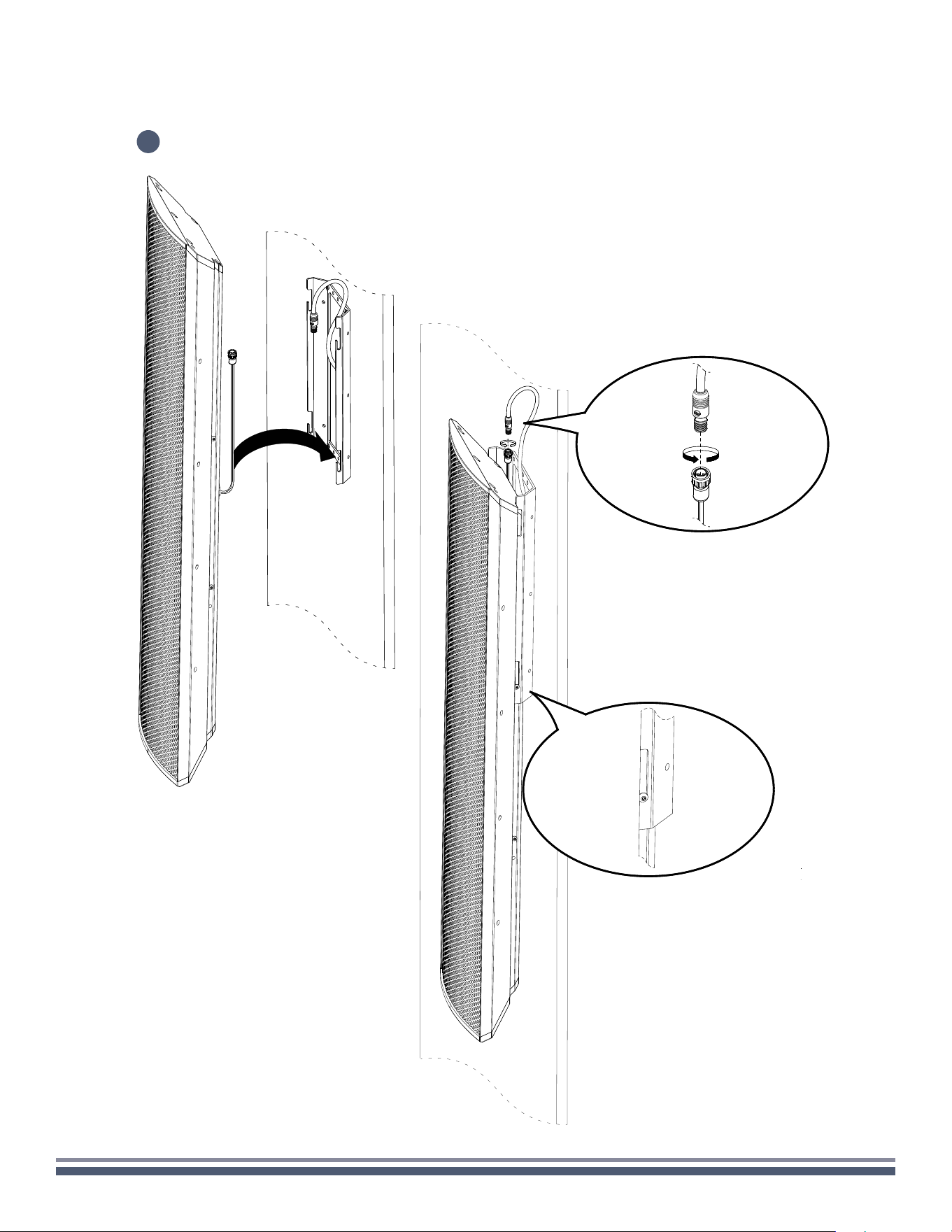
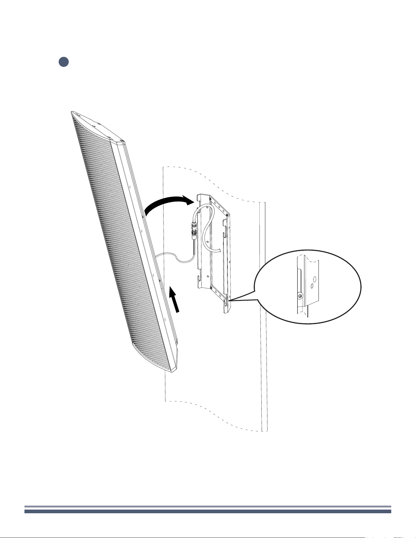
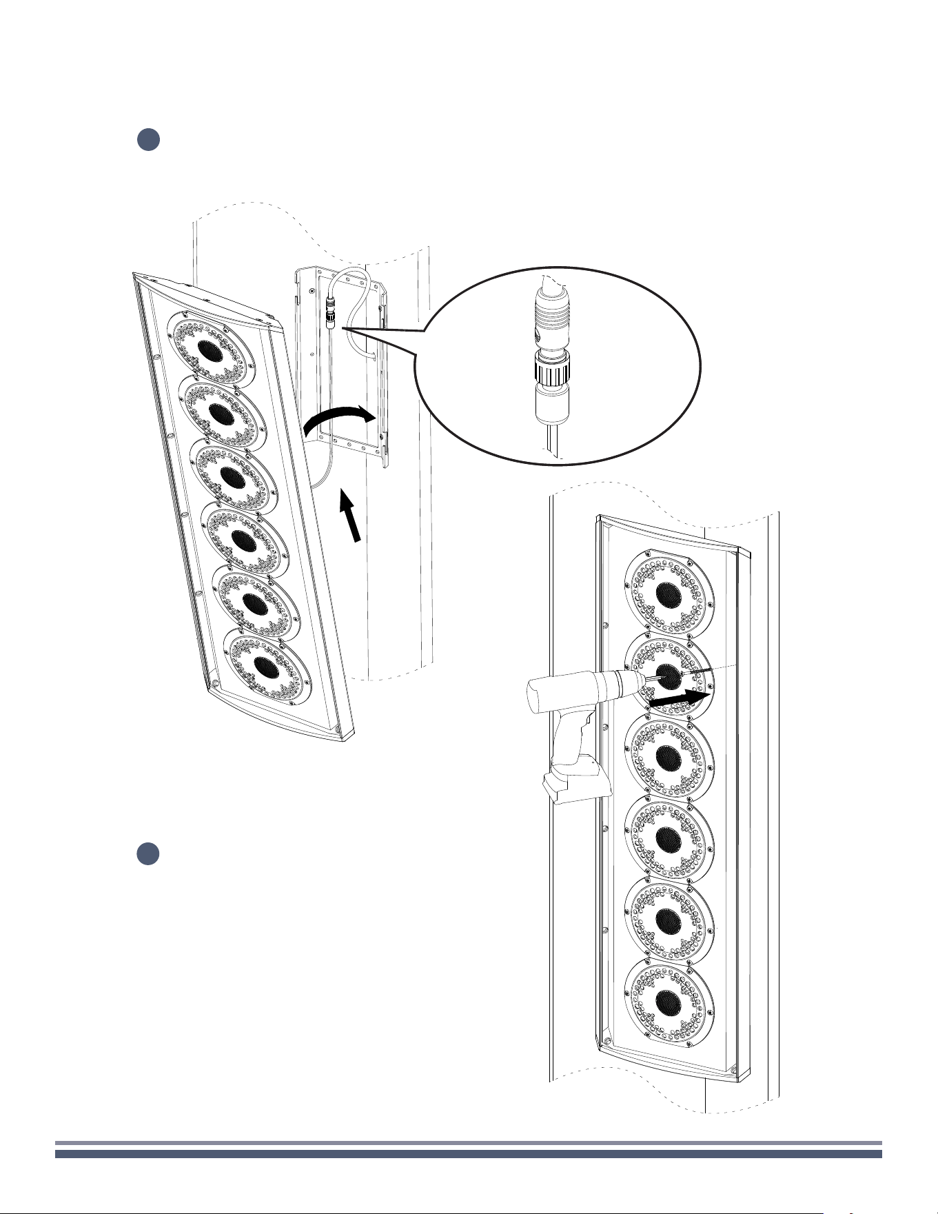
Pull speaker wire feeds up and temporarily place the speaker onto the mounting bracket by slotting the top two
screws into the bottom two bracket slots.
6
300 Series Razor Speaker User Guide | coastalsource.com 8
WALL
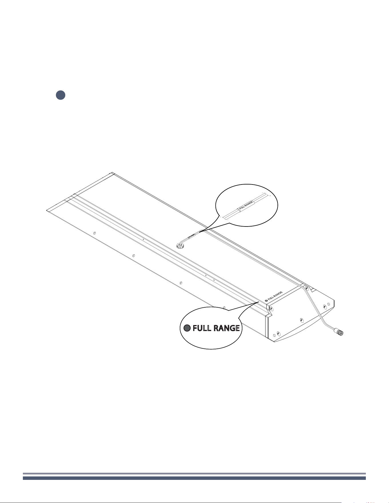
7
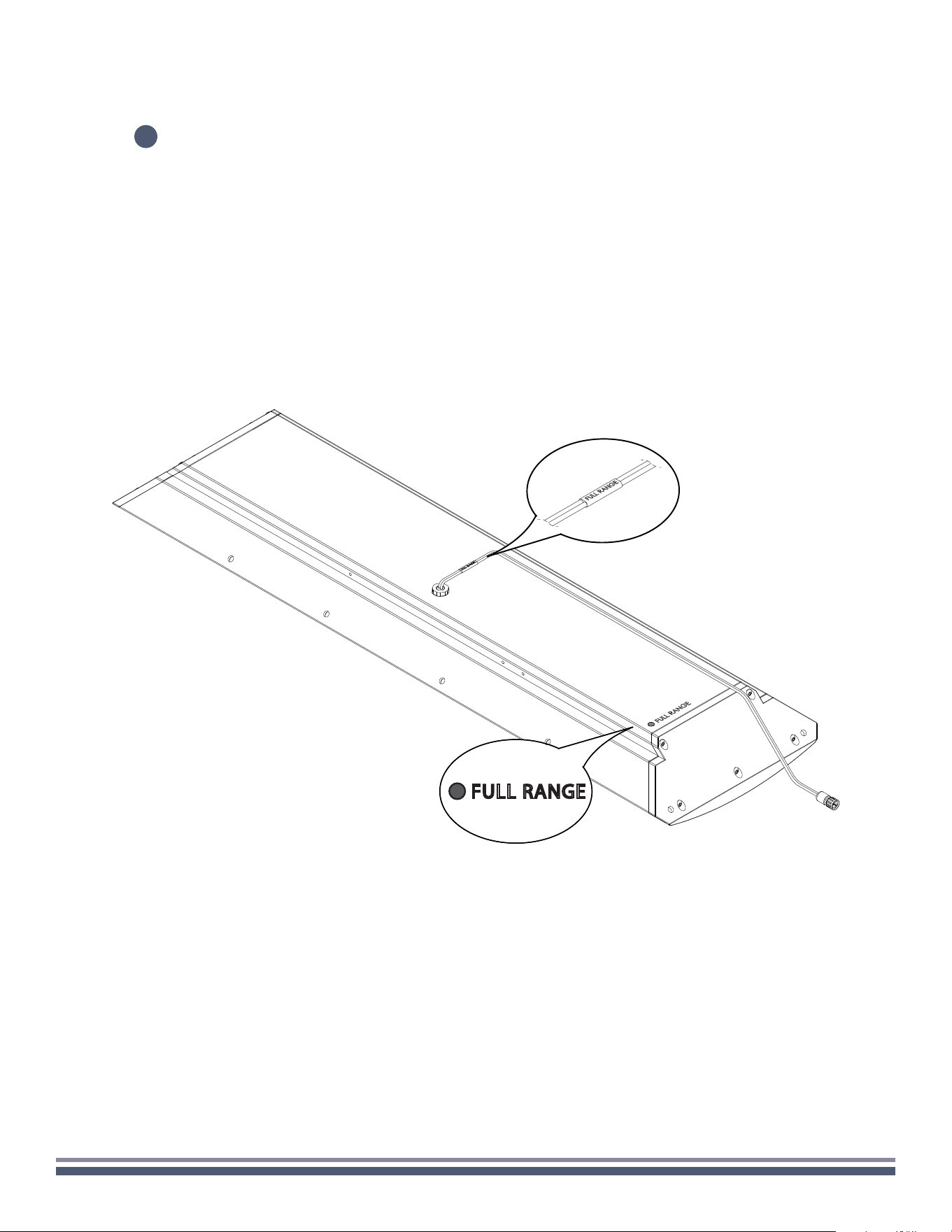
With speaker hanging on the mounting bracket, make necessary cable connections, paying close attention to the
color coding and labeling of the speaker inputs. (You can find the color codes relevant to your model on the back of
the enclosure in the lower left-hand corner. Failure to connect the speaker properly may void warranty and/or result
in permanent damage.)
FULL RANGE
300 Series Razor Speaker User Guide | coastalsource.com 9
WALL
8
Lift the speaker off the bottom slots and slide the speaker into its final
position with side screws sliding into top and bottom slots.
300 Series Razor Speaker User Guide | coastalsource.com 10
WALL
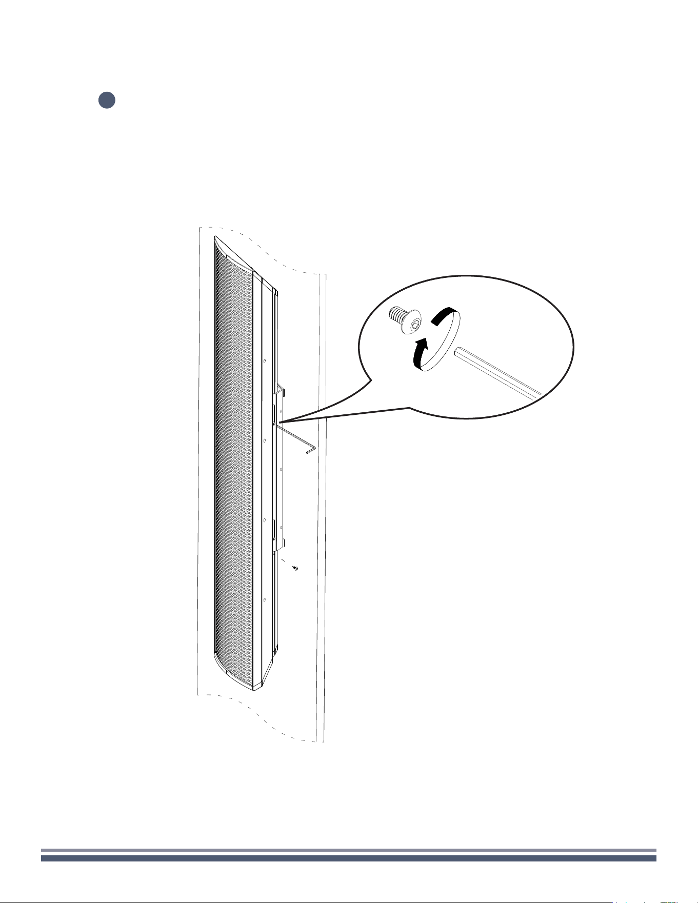
9
Install security screws into the bottom hole on each side of the enclosure and tighten all
the installed screws to ensure the speaker is secure on the mounting bracket.
300 Series Razor Speaker User Guide | coastalsource.com 11
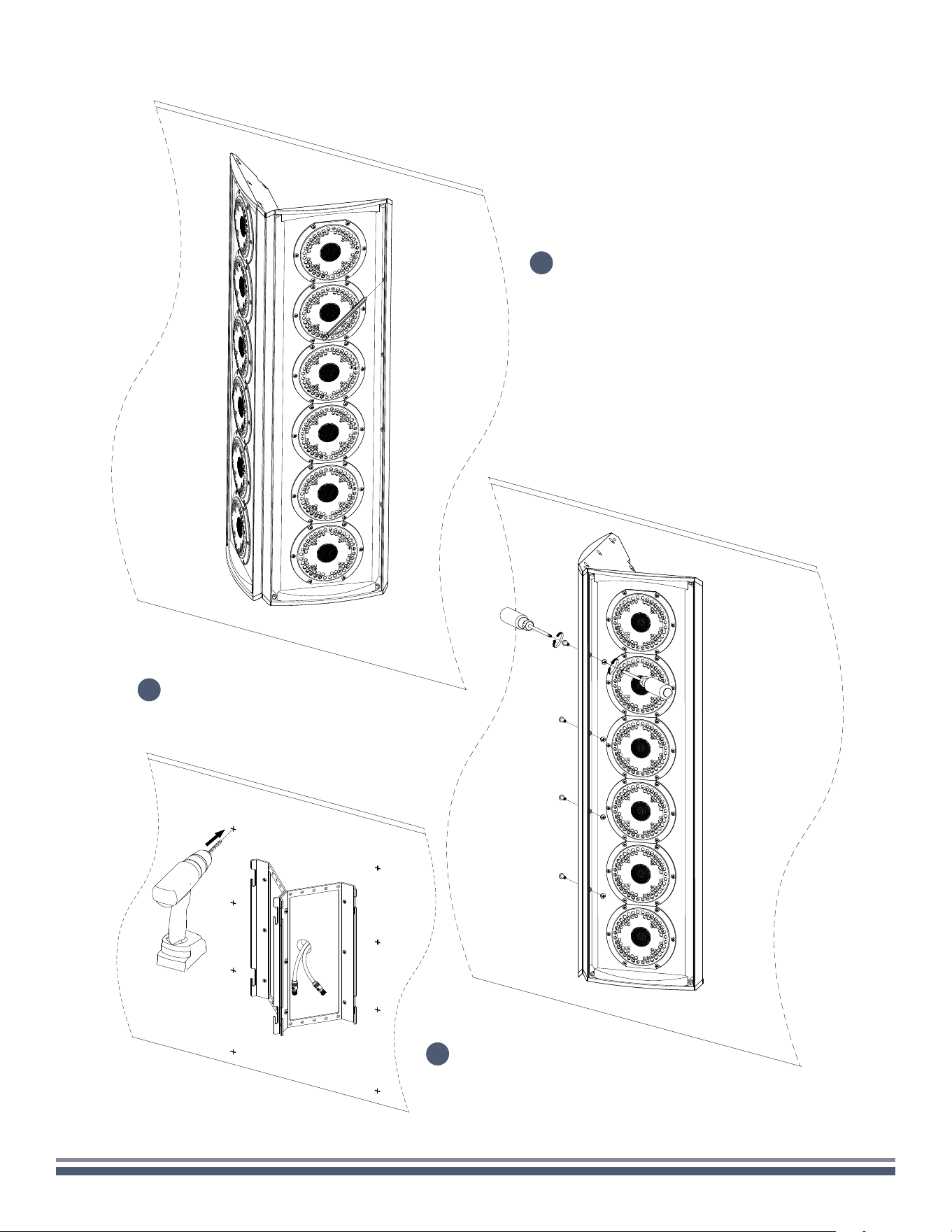
CORNER-CEILING
Carefully remove speaker assembly, RingKey, and foam strips from the box, setting
on a soft surface so as not to mar the finish.
Using a 3/32" Hex Key, remove the two locking screws beneath the attached speaker mount,
and loosen the four screws attaching the mount to the speaker so that the mount moves freely.
Remove the mount from the speaker.
1
2
1x
1x

300 Series Razor Speaker User Guide | coastalsource.com 12
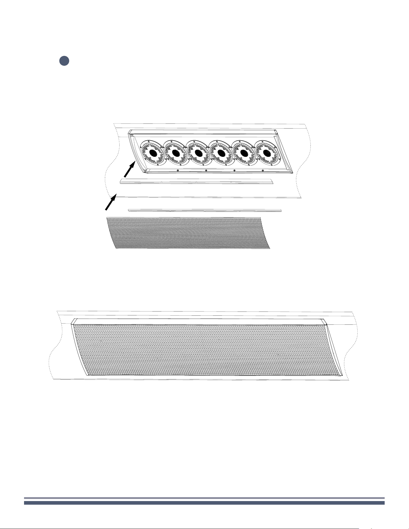
CORNER-CEILING
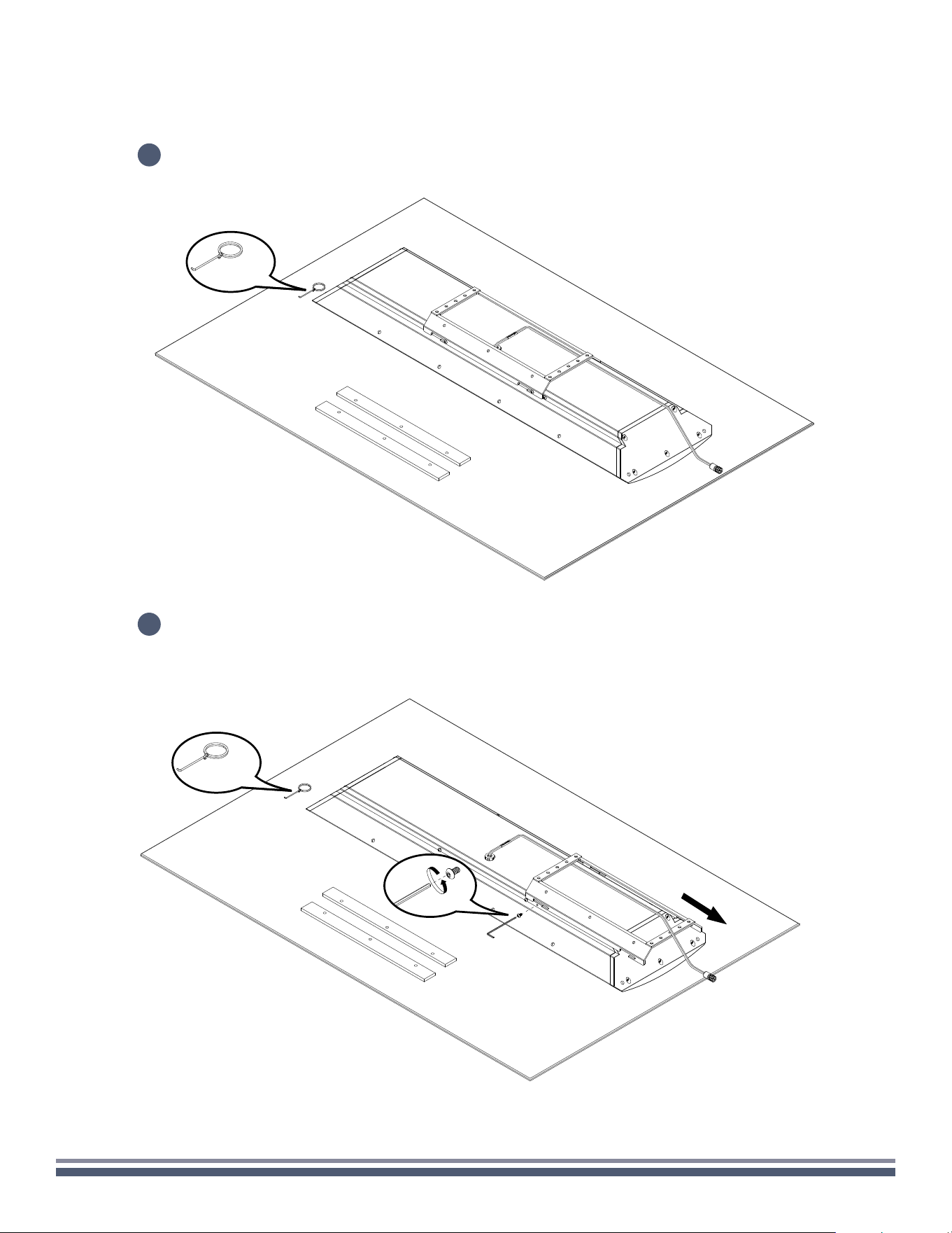
3
Carefully insert the included RingKey into a
hole in the grille and pull to remove.
Set grille aside and remove the rubber
stripping along the long edges of the
speaker enclosure.
Adhere the large foam strips to the 45
degree corners of the mounting bracket.
300 Series Razor Speaker User Guide | coastalsource.com 13
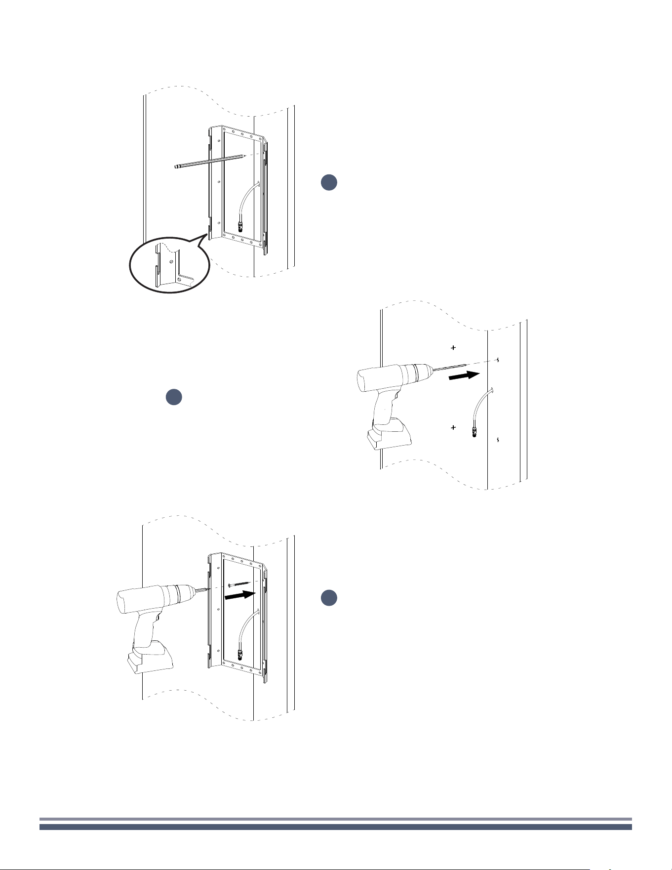
CORNER-CEILING
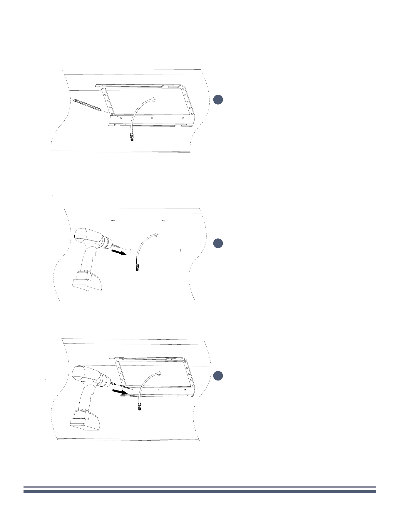
Determine the installation location on the
ceiling/wall corner, mark the four holes using the
bracket as a template for pilot holes (if necessary),
while taking note of the slot direction.
NOTE: You must maintain this direction throughout
installation.
If needed, drill pilot holes at each marked location.
Place mounting bracket back against the wall
in the intended location. Using the appropriate
fasteners, secure the mount to the wall.
4
5
6
300 Series Razor Speaker User Guide | coastalsource.com 14
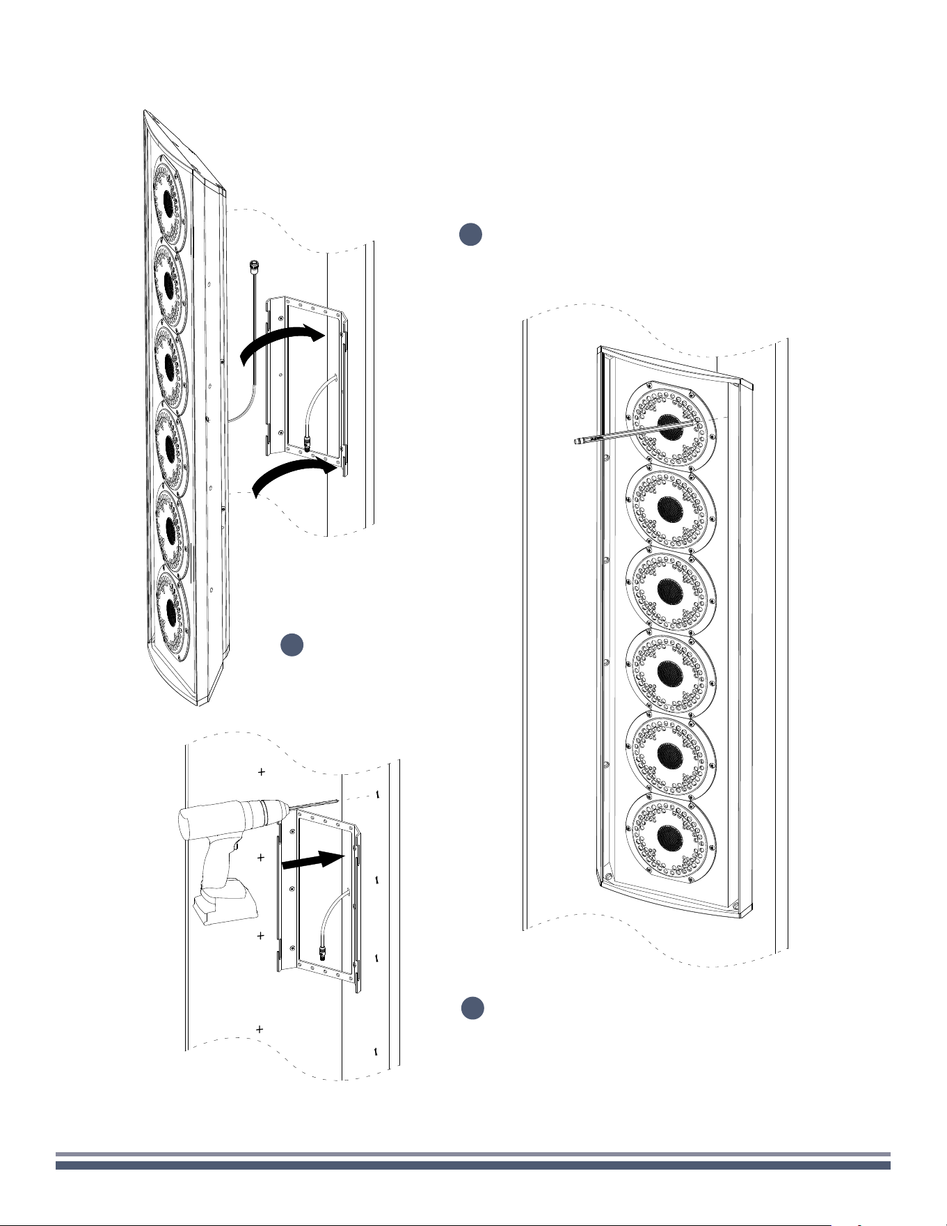
CORNER-CEILING
Remove the enclosure, then proceed to drilling
the markings to create pilot holes.
Tape the wire from the wall before sliding the
installed screws of the enclosure into the slots to
used it as template for marking the pilot holes.
7
Mark the holes on both sides for
pilot drilling (if necessary).
8
9
300 Series Razor Speaker User Guide | coastalsource.com 15
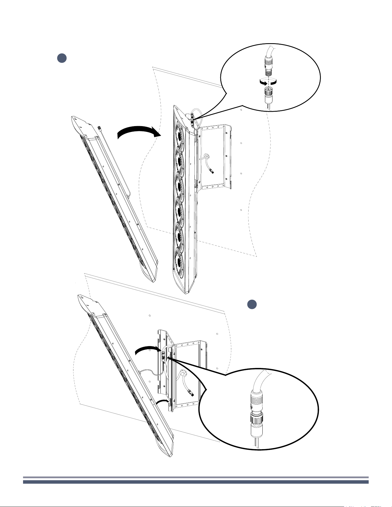
CORNER-CEILING
After drilling the pilot holes, hang the
installed screws of the enclosure into
the slot of the bracket making sure the
speaker wires are pulled to the left and
accessible.
10
300 Series Razor Speaker User Guide | coastalsource.com 16
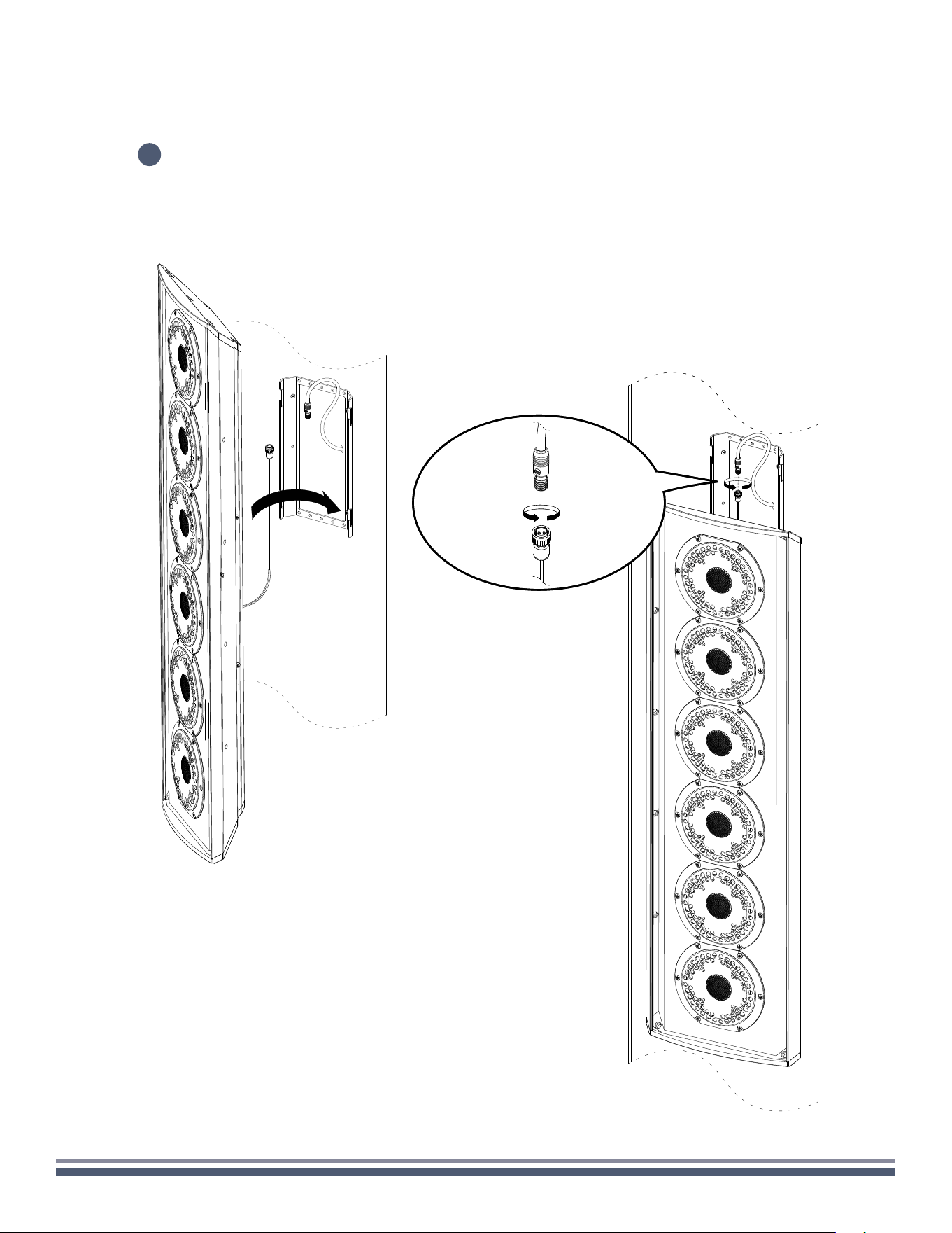
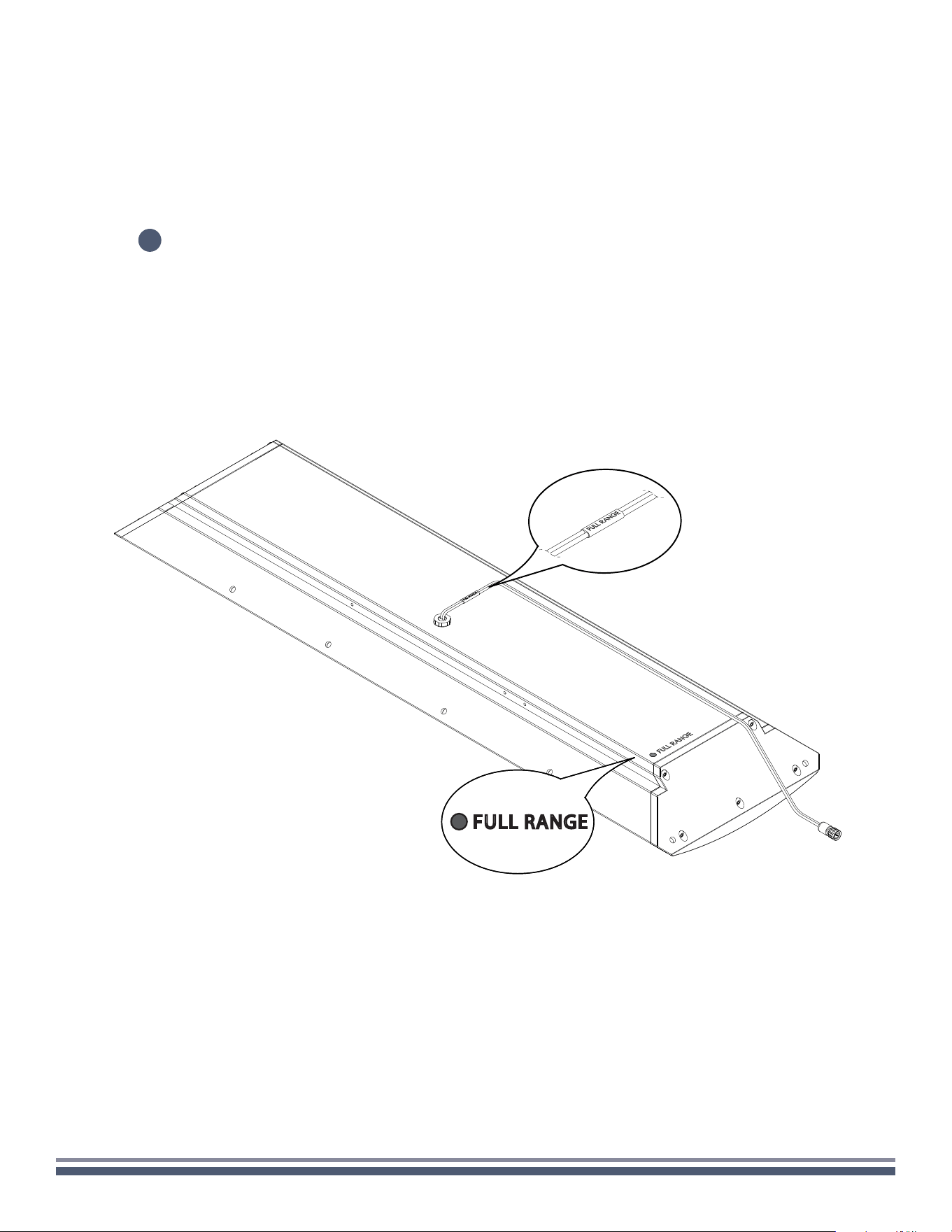
CORNER-CEILING
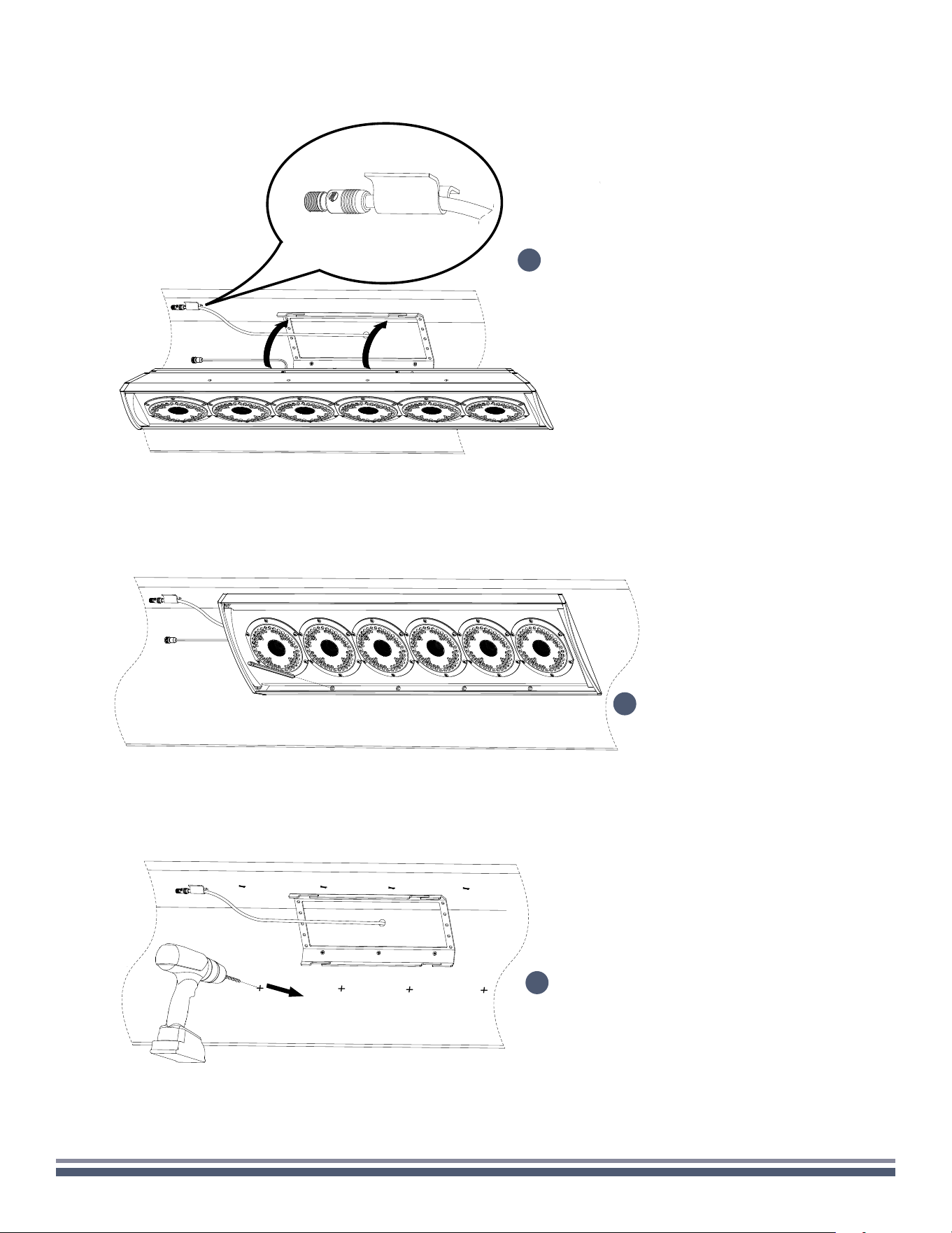
11
Proceed to make all necessary wiring connections, paying close attention to the color coding and labeling of the
speaker inputs below. You can find the color codes relevant to your model on the back of the enclosure in the
lower lefthand corner. Failure to connect the speaker properly may result in permanent damage and void warranty.
FULL RANGE
300 Series Razor Speaker User Guide | coastalsource.com 17
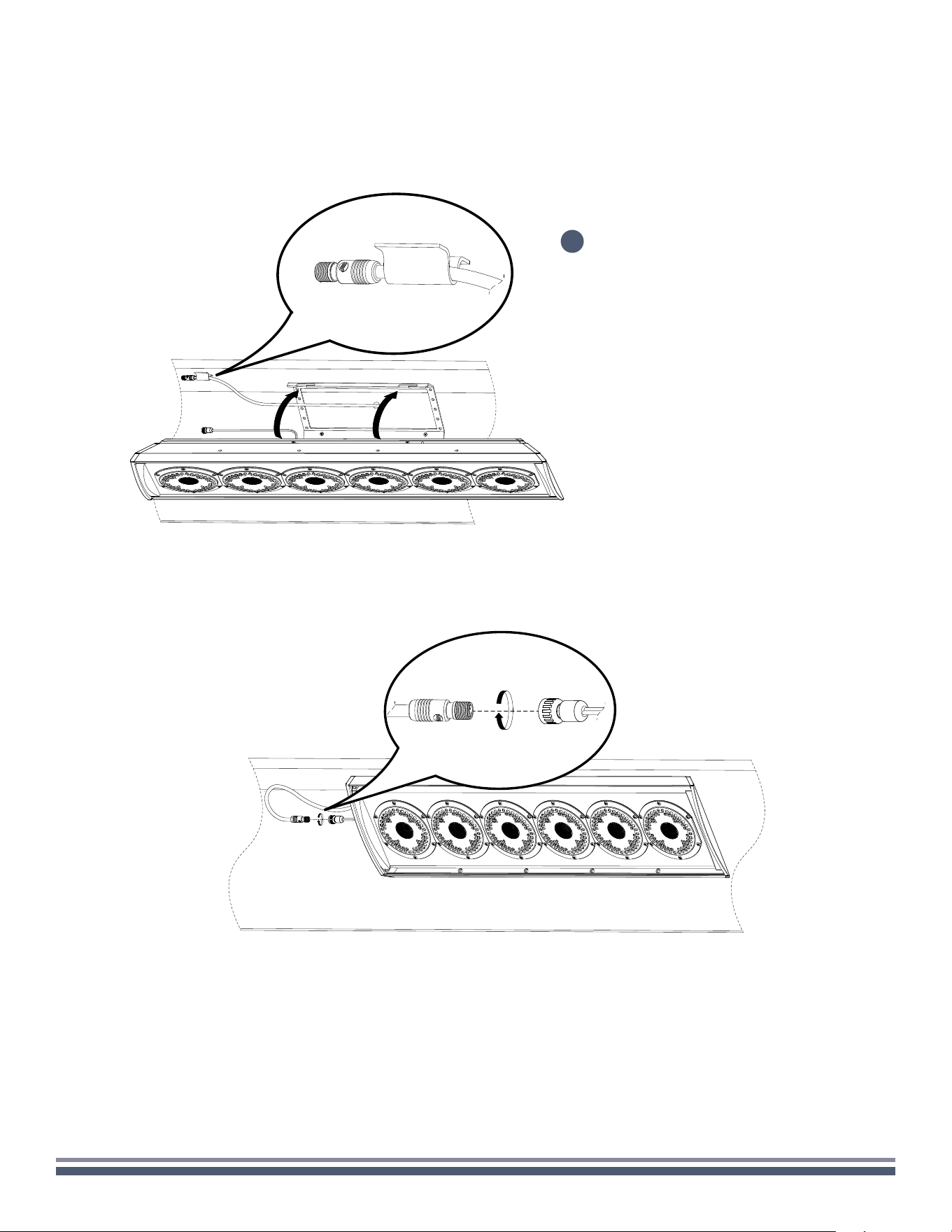
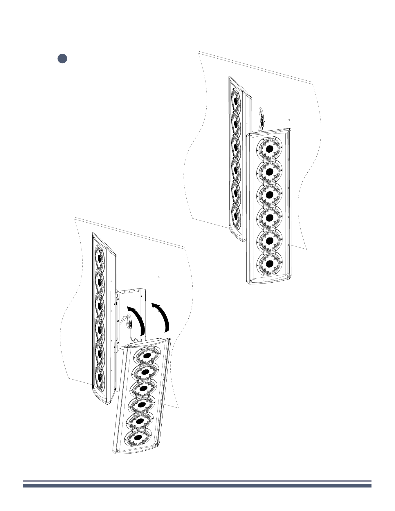
CORNER-CEILING
Once the wiring is properly connected, tuck in the wires on the back of the enclosure.
12
Using the appropriate fasteners,
secure the speaker to the wall.
13
300 Series Razor Speaker User Guide | coastalsource.com 18
CORNER-CEILING
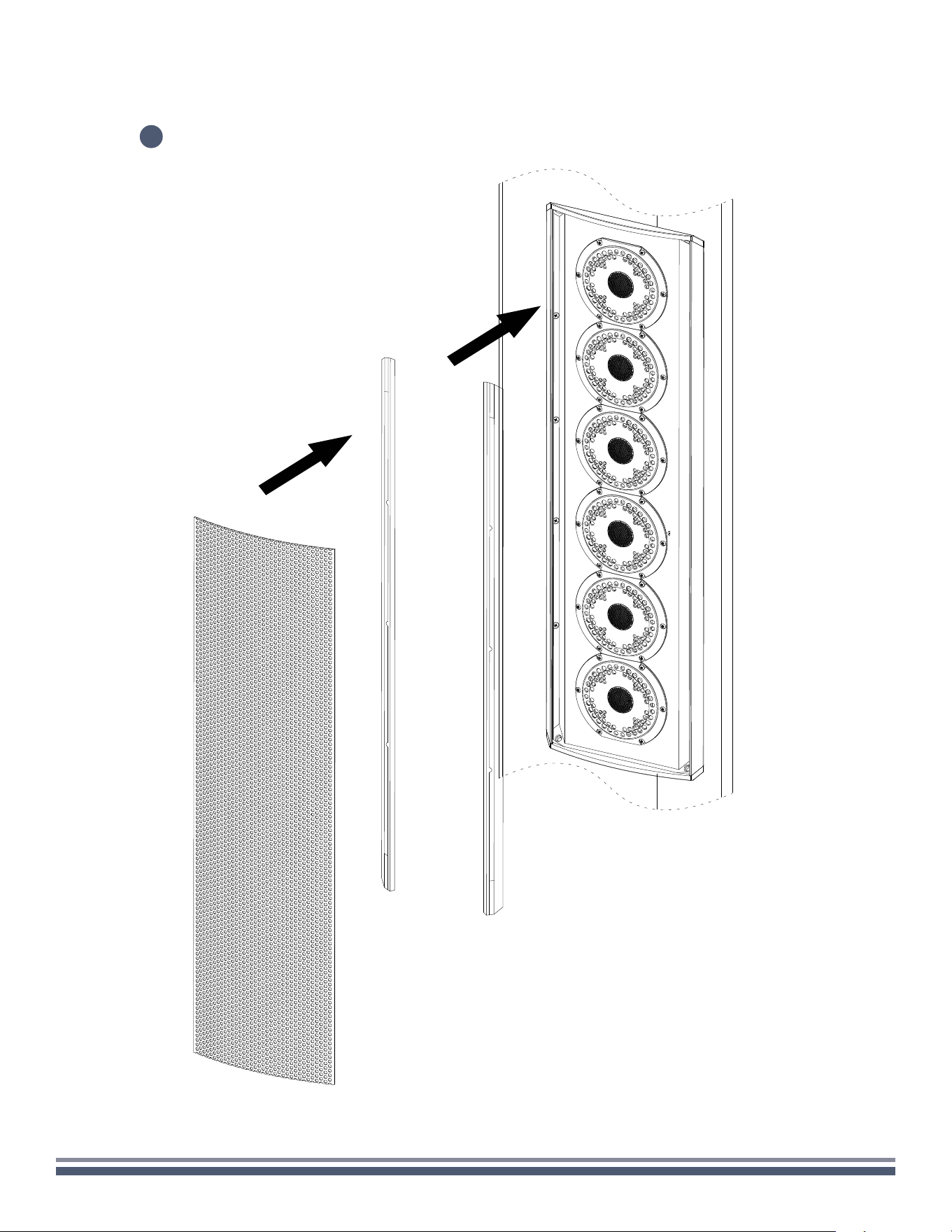
Reinstall rubber stripping into speaker enclosure before carefully reinstalling the grille.
14

300 Series Razor Speaker User Guide | coastalsource.com 19
CORNER-WALL
Carefully remove speaker assembly, RingKey, and foam strips from the box, setting
on a soft surface so as not to mar the finish.
Using a 3/32" Hex Key, remove the two locking screws beneath the attached speaker mount,
and loosen the four screws attaching the mount to the speaker so that the mount moves freely.
Remove the mount from the speaker.
1
2
1x
1x

300 Series Razor Speaker User Guide | coastalsource.com 20
CORNER-WALL
3
Carefully insert the included RingKey into a
hole in the grille and pull to remove.
Set grille aside and remove the rubber
stripping along the long edges of the
speaker enclosure.
Adhere the large foam strips to the 45
degree corners of the mounting bracket.
300 Series Razor Speaker User Guide | coastalsource.com 21
CORNER-WALL
Drill the markings to create pilot holes.
Determine the installation location on the wall corner,
mark the four holes using the bracket as a template
for pilot holes (if necessary), while ensuring the
mounting slots are facing upwards.
4
Using the appropriate fasteners,
secure the mount to the wall.
6
5
300 Series Razor Speaker User Guide | coastalsource.com 22
CORNER-WALL
Hang the upper screw of the Razor into the the
upper slot to used it as template for the holes.
Mark the holes on both side for pilot
drilling (if necessary).
8
7
Remove the enclosure, then
proceed to drilling the markings
to create pilot holes.
9
300 Series Razor Speaker User Guide | coastalsource.com 23
CORNER-WALL
After drilling the pilot holes, hang the two (2) upper screws of the
Razor into the the lower slot of the bracket making sure the speaker
wires are pulled upwards and accessible after the speaker is hung.
10
300 Series Razor Speaker User Guide | coastalsource.com 24
CORNER-WALL
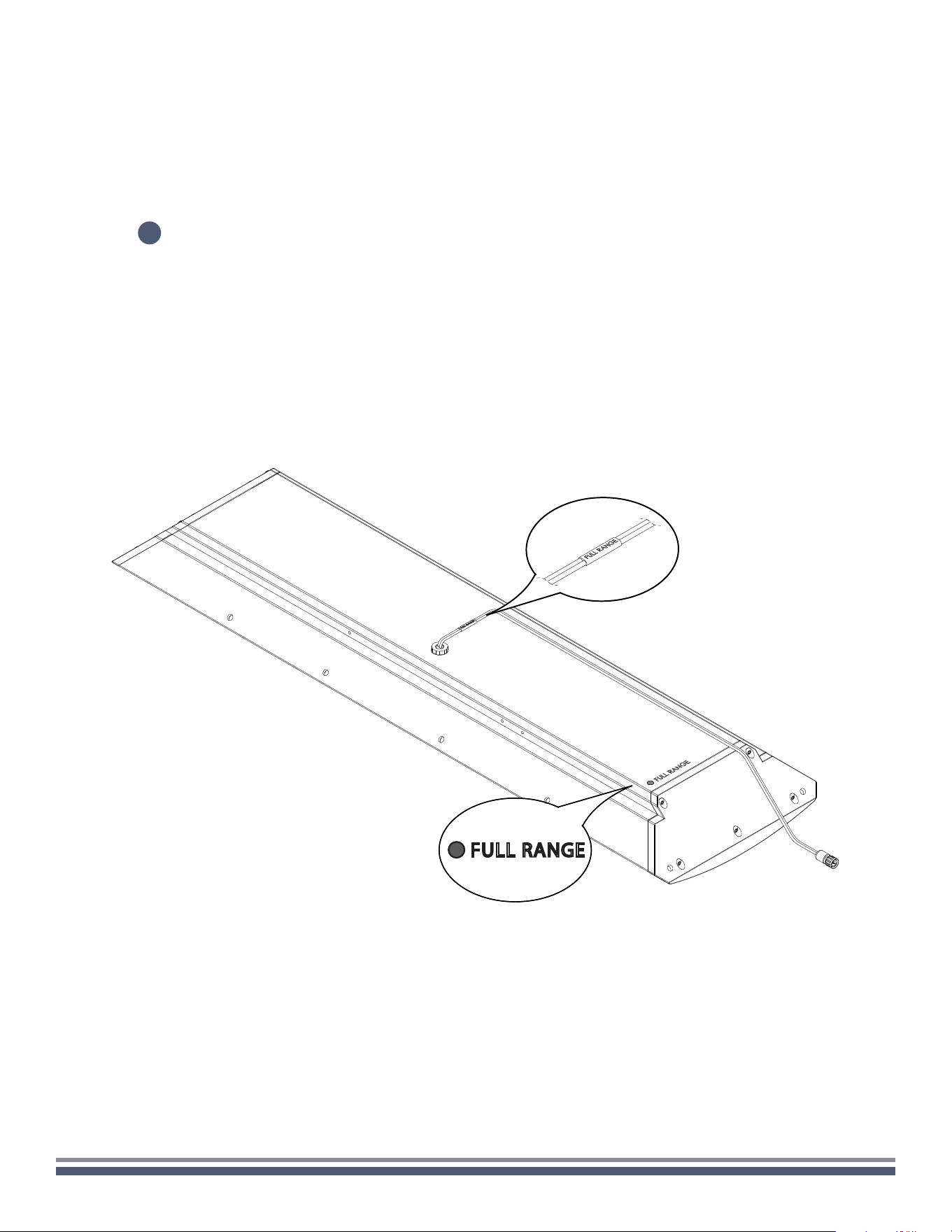
Proceed to make all necessary wiring connections, paying close attention to the color coding and labeling of the
speaker inputs below. You can find the color codes relevant to your model on the back of the enclosure in the
lower lefthand corner. Failure to connect the speaker properly may result in permanent damage and void warranty.
11
FULL RANGE
300 Series Razor Speaker User Guide | coastalsource.com 25
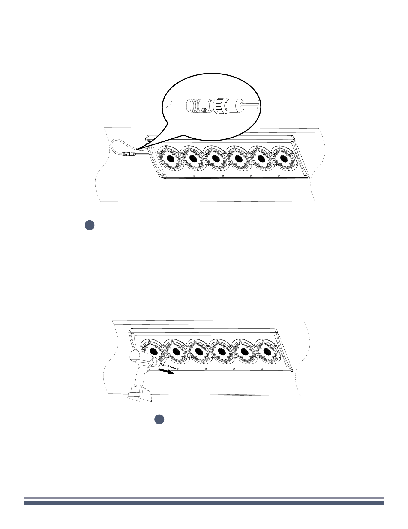
CORNER-WALL
Once the wiring is properly connected, lift the speaker off the bottom slots and
slide the enclosure into the top and bottom slots for the final installation.
12
Using the appropriate fasteners,
secure the speaker to the wall.
13
300 Series Razor Speaker User Guide | coastalsource.com 26
CORNER-WALL
Reinstall the diffraction edge strips on the side
then the grilles right after it.
14
300 Series Razor Speaker User Guide | coastalsource.com 27
DUAL STEREO

300 Series Razor Speaker User Guide | coastalsource.com 28
DUAL STEREO
Carefully remove speaker assembly, RingKey, and foam strips from the box, setting
on a soft surface so as not to mar the finish.
Using a 3/32" Hex Key, remove the two locking screws beneath the attached speaker mount,
and loosen the four screws attaching the mount to the speaker so that the mount moves freely.
Remove the mount from the speaker.
1
2
1x
1x
300 Series Razor Speaker User Guide | coastalsource.com 29
DUAL STEREO
3
Carefully insert the included RingKey into a
hole in the grille and pull to remove.
Set grille aside and remove the rubber
stripping along the long edges of the
speaker enclosure.
Adhere the large foam strips to the 45
degree corners of the mounting bracket.
300 Series Razor Speaker User Guide | coastalsource.com 30
DUAL STEREO
Join the two wall brackets together using 1/4” 10-32 barrel nuts.
4
300 Series Razor Speaker User Guide | coastalsource.com 31
DUAL STEREO
Place the mounting bracket assembly (ensuring
slots are facing up) on the wall in the intended
mounting location. Be sure that the speaker wire
penetration point is somewhat centered in the
bracket. With the help of a level, mark at least four
holes on the wall through rear of the brackets.
Remove the bracket assembly and drill the appropriate
sized pilot holes for your intended fasteners at the
marked location to prepare for final mounting.
6
5
300 Series Razor Speaker User Guide | coastalsource.com 32
DUAL STEREO
Again ensuring that slots are facing up,
place dual mounting bracket assembly
back against the wall in the intended
location. Using the appropriate fasteners,
secure the mount assembly to the wall.
Temporarily hang both speakers onto mounting
bracket assembly by sliding top and bottom
screws into mount slots. Secure speakers
together using three 1/4" barrel nuts.
7
8
300 Series Razor Speaker User Guide | coastalsource.com 33
DUAL STEREO
Mark the location for pilot holes
through the three holes on each
side of the speaker assembly.
Separate speakers by removing three
barrel nut assemblies and then remove
speakers from mount assembly. Set aside.
Drill the appropriate sized pilot holes for
your intended fasteners at the marked
locations to prepare for final mounting.
9
11
10
300 Series Razor Speaker User Guide | coastalsource.com 34
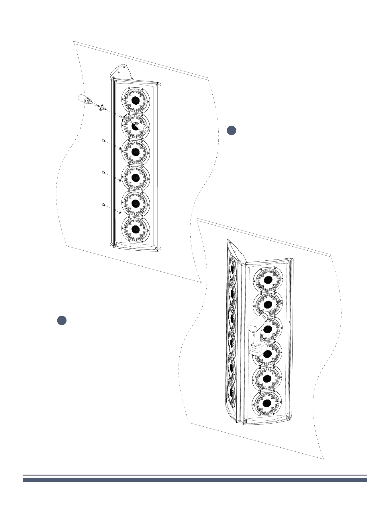
DUAL STEREO
With speaker hanging on the mounting bracket, make necessary cable connections, paying close attention to the
color coding and labeling of the speaker inputs. (You can find the color codes relevant to your model on the back
of the enclosure in the lower left-hand corner. Failure to connect the speaker properly may void warranty and/or
result in permanent damage.)
12
FULL RANGE
300 Series Razor Speaker User Guide | coastalsource.com 35
DUAL STEREO
13
Hang the two (2) upper
screws of the Razor into the
the lower slot of the bracket
making sure the speaker
wires are pulled upwards
and accessible after the
speaker is hung.
14
Once the wiring is properly
connected, lift the speaker
off the bottom slots and
slide the enclosure into the
top and bottom slots for the
final installation.
300 Series Razor Speaker User Guide | coastalsource.com 36
DUAL STEREO
!
Repeat steps 13 and 14
for the second speaker.
300 Series Razor Speaker User Guide | coastalsource.com 37
DUAL STEREO
Using the appropriate fasteners, secure
the speaker assembly to the wall.
Once again secure speakers together
using three 1/4" barrel nuts.
15
16
300 Series Razor Speaker User Guide | coastalsource.com 38
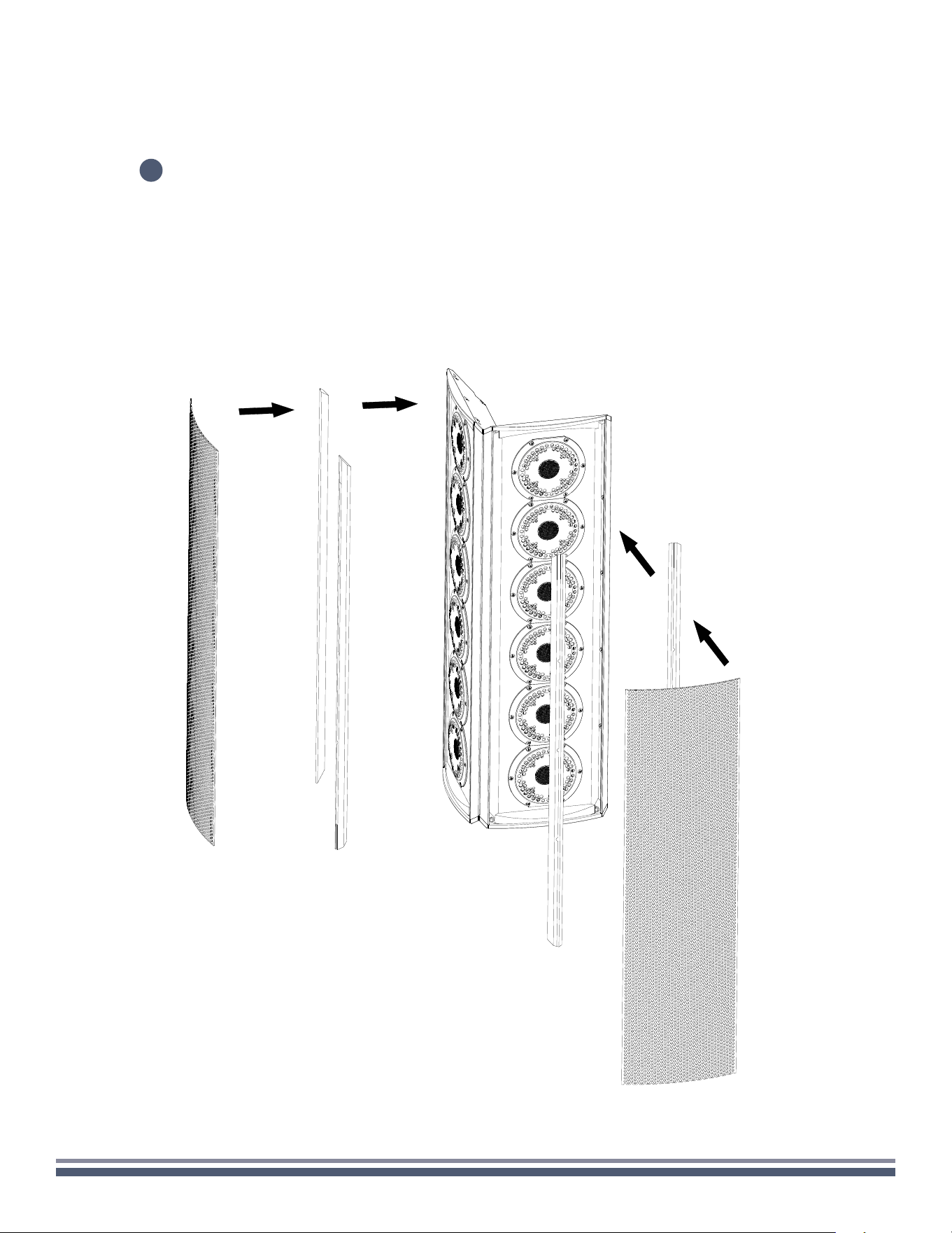
DUAL STEREO
Reinstall rubber stripping into both speaker
enclosures before carefully reinstalling the grilles.
17