Battery Analyzer
USER MANUAL
BT600 Plus


Safety Is Always the First Priority!
Multilingual User Manual
Section 1 What's in the Box?
Section 2 Product Overview
Section 3 Getting Started
Section 4 How to Use
Section 5 Review Data
Section 6 System Setup
Section 7 Update
Section 8 Replace Printer Paper
Section 9 Technical Specications
Section 10 FAQ
Section 11 Warranty
Compliance Information
......................
......................
......................
......................
......................
......................
......................
......................
......................
......................
......................
......................
......................
......................
4
6
6
7
11
16
35
37
40
41
42
43
44
45
CONTENTS
4
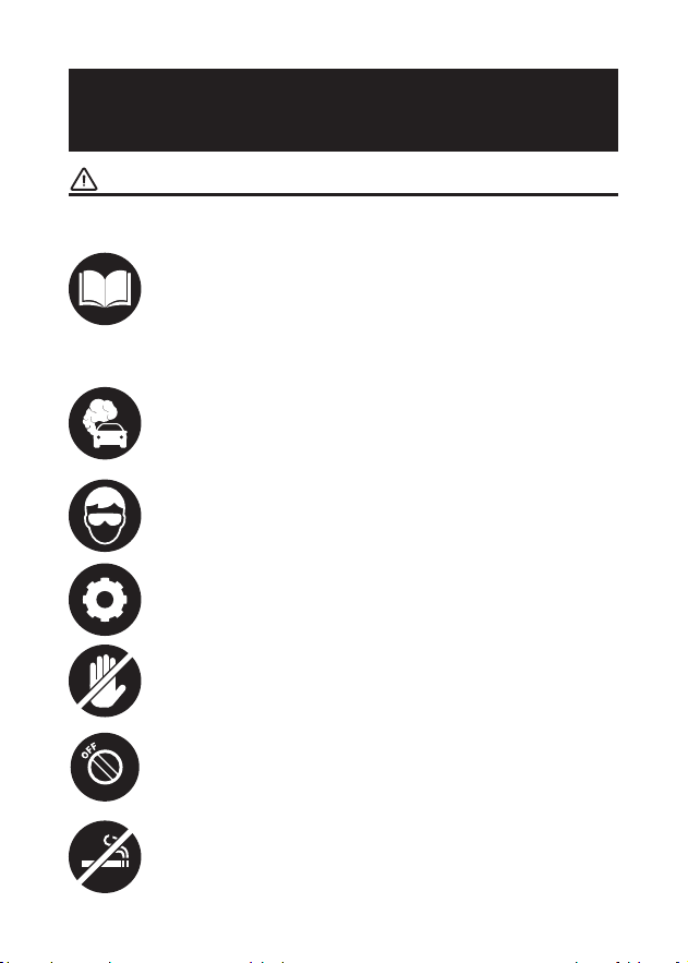
For your safety and the safety of others, as well as to
avoid any damage to the product and your vehicle,
carefully read and make sure you fully understand
this manual's safety instructions in its entirety. You
must read the vehicle's service manual, the battery
manufacturer's specic safeguards, and observe the
stated precautions or instructions before and during
any test or service procedure.
ONLY OPERATE TESTS IN A WELL-VENTILATED AREA
since the vehicle produces carbon monoxide (a
toxic, poisonous gas, and particulate matter) when
the engine is running.
ALWAYS BE AWARE OF MOVING PARTS (such as
coolant fans, pulleys, belts) since they spin or turn at
high speeds when the engine is running.
DO NOT TOUCH HOT ENGINE PARTS to prevent
severe burns. The motor parts can get extremely hot
when the engine is running.
TURN THE IGNITION OFF BEFORE CONNECTING OR
DISCONNECTING THE TOOL FROM THE BATTERY
to prevent damage to the device or the vehicle's
electronic components.
DON'T SMOKE NEAR THE VEHICLE when testing.
Fuel and battery vapors are highly ammable.
ALWAYS WEAR APPROVED SAFETY EYE
PROTECTION to prevent damage from sharp objects
and caustic liquids.
SAFETY IS ALWAYS THE
FIRST PRIORITY!
READ THE INSTRUCTIONS BEFORE USING

5
DO NOT WEAR LOOSE CLOTHING OR JEWELRY
WHEN WORKING ON AN ENGINE. Loose clothing can
easily be caught in the engine's fan, pulleys, belts,
etc., and jewelry is highly conductive, which may
cause severe burn or electric shock if it contacts
electricity.
DO NOT CUT THE PRODUCTS CORDS OR SUBMERGE
THEM IN WATER. The product is an electrical device
that can cause shock and severe burns.
WARNING: Battery acid is extremely corrosive. If acid
gets into your eyes, RINSE THEM THOROUGHLY WITH
COLD RUNNING WATER FOR AT LEAST 20 MINUTES
AND SEEK MEDICAL ATTENTION IMMEDIATELY.
If battery acid contacts your skin or clothing, WASH
IT IMMEDIATELY WITH A SOLUTION OF WATER AND
BAKING SODA.

6
SECTION 1
WHAT'S IN THE BOX?
MULTILINGUAL USER
MANUAL
BT600 Plus
Test Cable with Clamps x 2
USB Cable (USB-A to USB-C)
Four-in-one Charger
5 Rolls of Printer Paper
Carrying Bag
User Manual
Quick User Guide
To download the multilingual user manual, please go to www.
topdon.com/products/BT600-Plus and enter the Download
page. Alternatively, you can scan the QR code below.
7
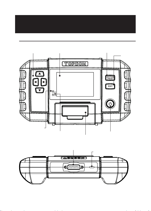
SECTION 2
PRODUCT OVERVIEW
Hardware Overview
Figure 2.1.1
①④
⑥
⑦
⑧
⑤
②
③
⑨
⑩

8
Display
ENTER/PRINT
EXIT
Arrow Keys
Power Button
Red LED Indicator
Green LED Indicator
Compartment for
Printer Paper
DB15 Male Connector
USB-C Port
Name
3.5 inches
Press the button to conrm an
option or message, or to print
the test results.
Press the button to go back to
the previous page.
Press the four buttons to
move the cursor in the desired
direction on the screen.
Long press to turn on or off the
analyzer. Short press to go back
to the home screen.
Illuminated when the device is
powered on.
Blinking during printing.
Intended to hold a roll of print
paper.
Designed to connect to the
tested battery using the test
cable with clamps.
Used for charging and update.
Description
①
②
③
④
⑤
⑥
⑦
⑧
⑨
⑩
Item
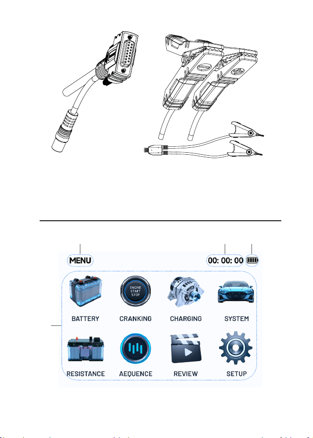
9
DB15 Female Connector Test Clamps (2 sets)
Interface Overview
Figure 2.1.2
③②①
④

10
Interface name
Current time
Battery status
(It ashes white while charging, red with a low battery
icon at low power, red with a full battery icon at high
temperature, and blue with a full battery icon at low
temperature.)
Function and message area
Description
①
②
③
④
Item
11
SECTION 3 GETTING STARTED
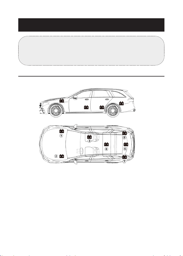
Where is the battery of a car located?
Let's take the following picture as a reference:
Figure 3.1.1
1) Most models hold the battery in the engine bay, under the
hood, in one of the front corners. See battery location
①
and
②
in Figure 3.1.1.
2) To balance uneven weight distribution, some manufacturers
hold the engine in the trunk. See battery location
⑤
,
⑥
, and
⑦
in Figure 3.1.1. In this case, the battery may have a plastic
cover that should be removed prior to any testing.
3) For some models, the battery might be stored underneath the
rear seat. See battery location
④
in Figure 3.1.1.
4) For other vehicles, the battery can be located underneath the
front passenger seat. See battery location
③
in Figure 3.1.1.
Note:
Make sure the device is adequately charged before use. It
is recommended to charge via the USB-C port using the
supplied adapter.
12
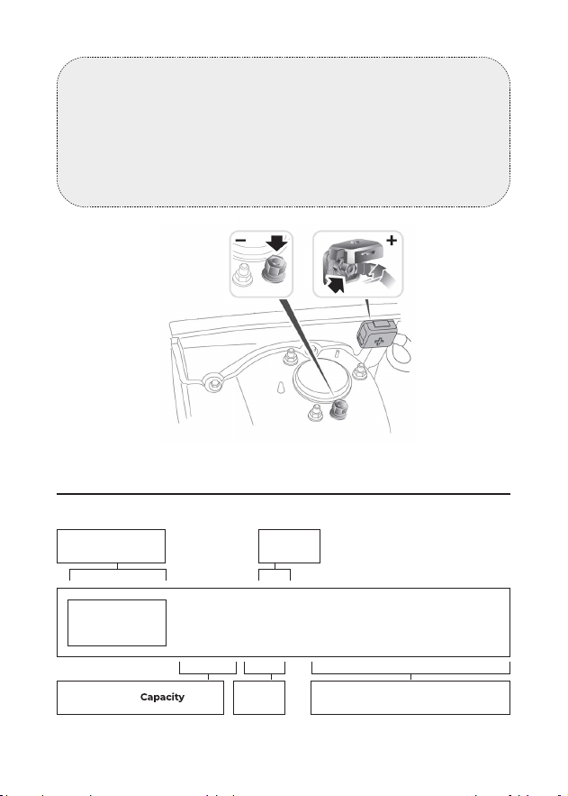
Figure 3.1.2
Figure 3.2.1
How to Identify What Type of Battery You Have?
Let's take the following picture as an example:
Manufacturers
Part No.
80Ah 12v
CCA in USAVoltage
650
A
(SAE)
AGM
E51
Battery
Type
Battery
WARNING:
DO NOT TEST THROUGH THE JUMPSTART POSTS. For
models that hold the battery under the seat or in the trunk,
the manufacturer usually includes jumpstart connector
conductor posts under the hood (see Figure 3.1.2) to make
jumpstarting easier. However, to ensure data accuracy
and operation safety, DO NOT CONNECT THE BATTERY
ANALYZER TO THE JUMPSTART POSTS.

13
1) Battery Capacity: 80Ah
Battery Capacity is dened as the total amount of electricity
generated in the battery in a certain time, and is measured in
ampere hours (Ah).
2) Battery Type: AGM
Please refer to this list to check the most commonly seen lead-
acid battery types for your reference.
Flooded Lead
Acid Battery
(Wet):
Enhanced
Flooded Battery
(EFB):
Gel Cell Battery
(Gel) & VRLA
Battery:
Absorbent Glass
Mat Battery
(AGM):
Name
This is the oldest/most common car battery type,
also known as "SLI battery." The Flooded Battery
is usually made of 6 cells with a liquid electrolyte
solution of sulfuric acid and water that needs to
be topped off periodically. This battery typically
supplies a voltage of 12.6V at full charge.
This battery type also uses a liquid electrolyte
solution. However, but unlike the Wet Flooded
Lead Acid battery, it is sealed and maintenance-
free. The Enhanced Flooded, usually seen in cars
with simple start-stop technology, can provide
up to 85,000 engine cranks.
Gel batteries are similar to ooded batteries,
but instead of antimony, calcium is used in the
lead plates. Additionally, silica is added to the
electrolyte solution, transforming the liquid into
a gel.
AGM batteries are designed to deliver powerful
bursts of starting amps and run for a long time.
"Absorbed Glass Mats" are used to cushion the
ultra-thin lead plates, allowing manufacturers to
include more leads into one battery and provide
more power. AGM batteries are divided into
two categories according to the cell structure.
They can be AGM FLAT PLATE and AGM SPIRAL.
This type of battery is ideal for vehicles with
automatic start-stop applications and braking
energy recovery.
Description

14
3) Voltage: 12V
When fully charged, automotive batteries should measure at
12.6 volts. However, this measurement should be from 13.7 to
14.7 when the engine is running. If the battery analyzer reads
less than this standard, it means that the battery's resting
voltage is weak. In this case, typically, the battery needs to be
charged or replaced.
4) CCA: 650A (SAE)
The CCA rating refers to how many amps a 12-volt battery
can deliver at 0°F in 30 seconds while maintaining at least a
7.2V voltage. This means that the higher the CCA rating is, the
easier the engine can be cranked in cold temperatures.
Preparation before Connection
1. Inspect the battery analyzer for any visible damage. Do not
use the device if it is damaged.
2. Check the test cable and clamps for any signs of wear
or damage. Only use cables and clamps that are in good
condition.
3. Securely connect the test cable to the device and tighten
the bolts properly.
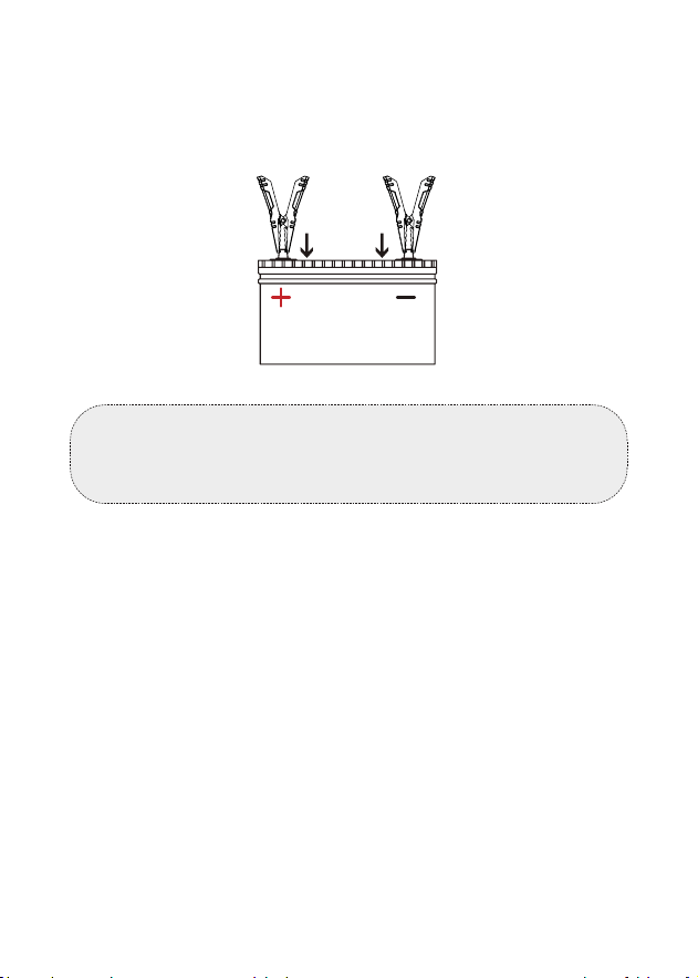
1) Before connecting the clamps to the terminals, please use
sandpaper to polish off the corrosion on the battery terminals.
With this, you can avoid inaccurate test values.
2) Attach the red clamp to the positive (+) terminal, and connect
the black clamp to the negative (-).
• ALWAYS KEEP THE RED & BLACK CLAMPS FROM
TOUCHING.
Connect the Clamps to the Battery Terminals (See
Figure 3.3.1)
Note:
Choose the appropriate clamps based on the size of the
battery. Both of the two sets of clamps supplied are suitable
for testing batteries.
15
• ALWAYS DISCONNECT THE NEGATIVE CABLE FROM THE
BATTERY FIRST AND RECONNECT IT LAST.
3) Once the clamps are properly connected, the battery analyzer
will power on automatically and be ready to conduct tests.
Note:
The BT600 Plus can be powered on by its built-in batteries
or the connected vehicle battery.
(Red) (Black)
Figure 3.3.1
16
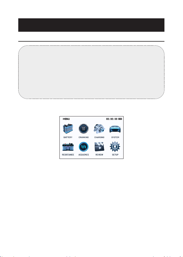
1) Select BATTERY and press [ENTER / PRINT].
2) Select the voltage of the battery to be tested from three
options: 6V, 12V and 24V and press [ENTER/PRINT].
3) Select the corresponding battery type and press [ENTER
/ PRINT]. The specic battery type is usually listed on the
battery label.
Figure 4.1.1
SECTION 4 HOW TO USE
Battery Test
WARNING:
Before testing in the vehicle, ensure all accessory loads are
off, the key is removed from the ignition, and the doors
are closed. If the vehicle was running prior to the test,
turn on the headlights to discharge the battery’s surface
charge. Allow the battery to rest for at least 1 minute to
recover before proceeding with the test. The battery testing
function applies to 6V, 12V and 24V lead-acid batteries.

17
BATTERY TYPE
REGULAR FLOODED
AGM FLAT PLATE
AGM SPIRAL
GEL
EFB
Figure 4.1.2
4) Select the corresponding battery standard and press [ENTER /
PRINT]. The specic battery standard will also be listed on the
battery label.
Please refer to the following table for specic battery
standards and test ranges.
STANDARD
CCA
CA
DIN
JIS
EN
TEC
GB
Figure 4.1.3
Cold Cranking Amps, specied by
SAE & BCI, most frequently used
value for starting battery at 0°F(-
18°C)
Battery Council International
standard
Description
100-2000
100-2000
Measurement
Range
CCA
BCI
Measure
-ment
Standard

18
Cranking Amps standard,
effective starting current value at
0°C
Marine Cranking Amps standard,
effective starting current value at
0°C
Japan Industrial Standard,
displayed on the battery as
combination of the numbers and
letters, e.g., 55D23,80D26
German Auto Industry
Committee Standard
International Electrotechnical
Commission Standard
European Automobile Industry
Association Standard
Society of Automotive Engineers
Standard
China National Standard
100-2000
100-2000
26A17-245H52
100-1400
100-1400
100-2000
100-2000
30Ah-220Ah
CA
MCA
JIS
DIN
IEC
EN
SAE
GB
5) Input the CCA by using the ▲/▼ keys and press [ENTER /
PRINT] to start the test.
Note:
You can short press the ▲/▼ keys to increase or decrease the
value by 5 each time, or you can press and hold the ▲/▼ keys
to continuously increase or decrease the value.

19
SET RATE
600CCA
CCA
Figure 4.1.4
6) The test result will appear soon on the tool's display.
100% 599CCA
46% 12.27V
03.65mΩ
600CCA(CCA)
BATTERY
GOOD BATTERY
HEALTH
CHARGE
INTERNAL R
RATED
Figure 4.1.5
To understand the test results, please refer to the chart below.
Good battery condition
Good battery condition, please charge
the battery
Please replace the battery
Please charge the battery and then
test again
Bad battery cell, please replace now
Normal battery condition
Explanation
GOOD BATTERY
GOOD, RECHARGE
REPLACE BATTERY
CHARGE RETEST
BAD CELL, REPLACE
NORMAL
Test Result

20
Battery Test Terminology:
The state of health shows the difference
between the battery being tested and a new
battery, considering cell aging. The SOH is
dened according to the maximum battery
charge ratio and its capacity.
The state of charge describes the difference
between a fully charged battery and
the same battery in use. It analyses the
remaining quantity of electricity available in
the cell. The SOC is established according to
the battery's remaining charge ratio, divided
by the maximum charge that the battery
can deliver.
The internal resistance is the opposition
to the current ow presented by the cells
and the battery itself, generating heat. Its
electronic resistance and ionic resistance
directly impact this indicator.
The CCA value you entered in the previous
step, that is, the CCA value listed on the
battery label. The difference of the rated CCA
between the actual CCA determines the test
result to a certain extent.
Description
HEALTH (SOH)
CHARGE (SOC)
INTERNAL
R (Internal
Resistance)
RATED
Terminology
Normal battery condition, please
charge the battery
Pay attention to the battery condition
and charge the battery
Pay attention to the battery condition
NORMAL, RECHARGE
NOTE, RECHARGE
NOTE
21
7) To print the test result, press [ENTER/PRINT].
Note:
If the system prompts that the printing function is
unavailable, please follow the on-screen instructions to
charge the BT600 Plus or load a roll of printing paper.
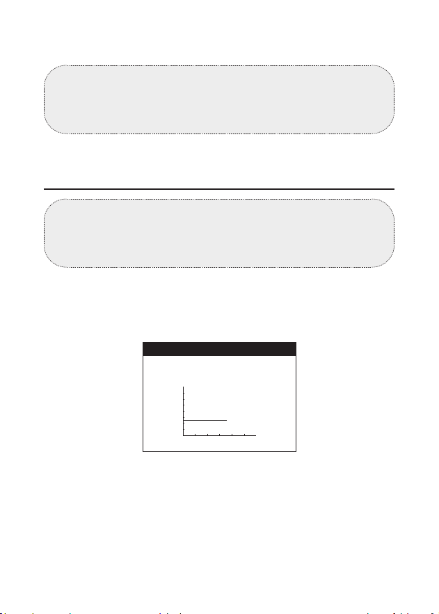
1) Select CRANKING and press [ENTER / PRINT].
2) The test will start by prompting you to crank the engine.
Follow the instructions and start the engine.
CRANKING
PLEASE START ENGINE
16
0
12V
24V
Figure 4.2.1
Cranking Test
WARNING:
Before the cranking test, the engine and all other accessory
loads must be off in order to ensure accurate results. This
test applies to both 12V & 24V lead-acid batteries.

22
• Cranking Time refers to the time it takes for a vehicle to start
the engine.
• Cranking Voltage refers to the battery voltage while the
engine is starting.
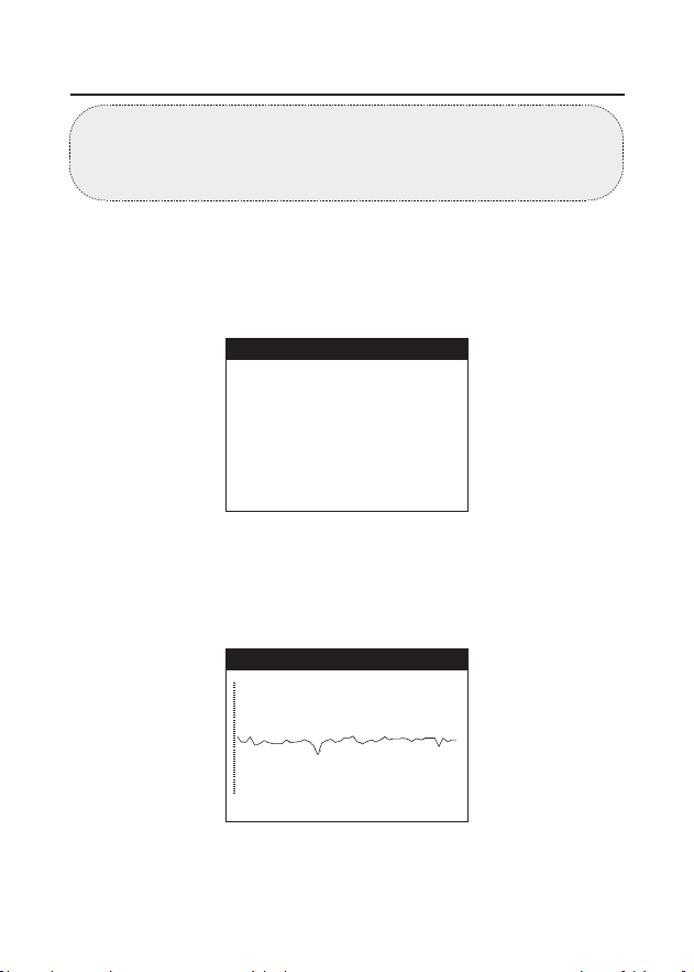
4) To print the test result, press [ENTER/PRINT].
CRANKING LOW
3) The test results will be displayed on the screen, showing the
voltage waveform during vehicle cranking along with the
cranking time and voltage reading.
CRANKING
0
12V
24V
Figure 4.2.2
TIME
2189ms
VOLTAGE
7.46V
23
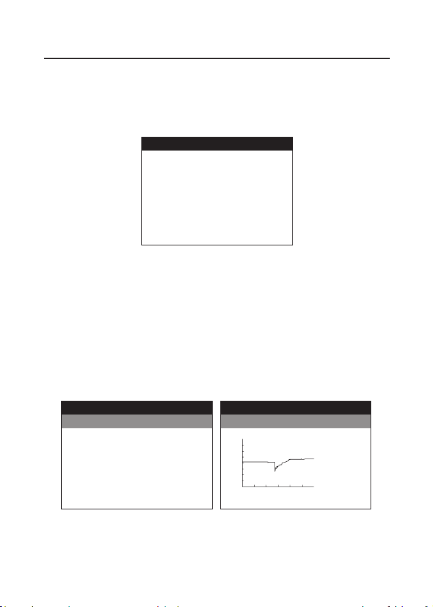
1) Select CHARGING from the home screen and press [ENTER /
PRINT].
2) Conrm the engine has been started and press [ENTER /
PRINT].
3) Ripple test will be conducted before the charging test starts.
The test result will be displayed in graph and will jump to the
next step after 5 seconds.
Charging Test
WARNING:
Always start the engine before performing the charging
test. This test applies to both 12V & 24V lead-acid batteries.
CHARGING
PLEASE START ENGINE, PRESS
"ENTER" TO CONTINUE.
Figure 4.3.1
13.86V 01mV
RIPPLE
Figure 4.3.2

24
CHARGING
TURN OFF LOADS, SUCH AS
HEADLIGHTS AND BLOWER MOTOR,
PRESS "ENTER" TO CONTINUE.
Figure 4.3.3
4) Turn off the loads, such as headlights and blower motor. Do as
requested and press [ENTER / PRINT].
5) Increase the speed to 2500 RPM. Do as requested and press
[ENTER / PRINT].
6) Release the throttle. Do as the requested and press [ENTER /
PRINT].
CHARGING
CHARGING
INCREASE SPEED TO 2500 RPM,
PRESS "ENTER" TO CONTINUE.
RELEASE THE THROTTLE, PRESS
"ENTER" TO CONTINUE.
Figure 4.3.4
Figure 4.3.6

25
7) Turn on the loads, such as headlights and blower motor. Do as
requested and press [ENTER / PRINT].
CHARGING
TURN ON LOADS, SUCH AS
HEADLIGHTS AND BLOWER MOTOR,
PRESS "ENTER" TO CONTINUE.
Figure 4.3.6
8) Increase the speed to 2500 RPM. Do as requested and press
[ENTER / PRINT].
9) Release the throttle and turn off the loads and engine. Do as
requested and press [ENTER / PRINT].
CHARGING
INCREASE SPEED TO 2500 RPM,
PRESS "ENTER" TO CONTINUE.
Figure 4.3.7
CHARGING
RELEASE THE THROTTLE AND
TURN OFF THE LOADS AND
ENGINE
, PRESS "ENTER" TO
CONTINUE.
Figure 4.3.8

26
10) The test result will appear on the display.
13.61V
14.01V
2mV
CHARGING
CHARGING NORMAL
LOADED
UNLOADED
RIPPLE
Figure 4.3.9
Loaded/Unloaded Voltage and Ripple:
11) To print the test result, press [ENTER/PRINT].
Loaded Voltage means the voltage measured when the on-
board electrical appliances are turned on.
Unloaded Voltage refers to the voltage measured when the
on-board electrical appliances are turned off.
Ripple: A vehicle’s battery operates on one-way direct
current (DC) electricity, while alternators output alternating
current (AC) electricity. In this process, the power needs to
go through the diode rectier to turn into a direct current -
that’s when the ripple occurs.
27
1) Select SYSTEM and press [ENTER / PRINT].
2) The system test will start in this process: Battery Test >
Cranking Test > Charging Test. Press [ENTER / PRINT].
System Test
SYSTEM
TESTING PROCESS
1. BATTERY TEST
2.CRANKING TEST
3.CHARGING TEST
Figure 4.4.1
3) Follow the on-screen instructions to complete battery test,
cranking test and charging test step by step.
For detailed operation, please refer to the parts of Battery Test,
Cranking Test and Charging Test in Section 4 respectively. The
difference is that the test result will ONLY appear at the end of
the whole system test.
4) The system will display the system results after all three tests
are complete.
100% 599CCA
46% 12.27V
03.65mΩ
600CCA(CCA)
BATTERY
GOOD BATTERY
HEALTH
CHARGE
INTERNAL R
RATED
Figure 4.4.2 Figure 4.4.3
CRANKING LOW
CRANKING
0
12V
24V
TIME
2189ms
VOLTAGE
7.46V

28
12.95V
12.96V
5mV
CHARGING
CHARGING NORMAL
LOADED
UNLOADED
RIPPLE
Figure 4.4.4
5) To print the test result, press [ENTER/PRINT].
29
Figure 4.5.1
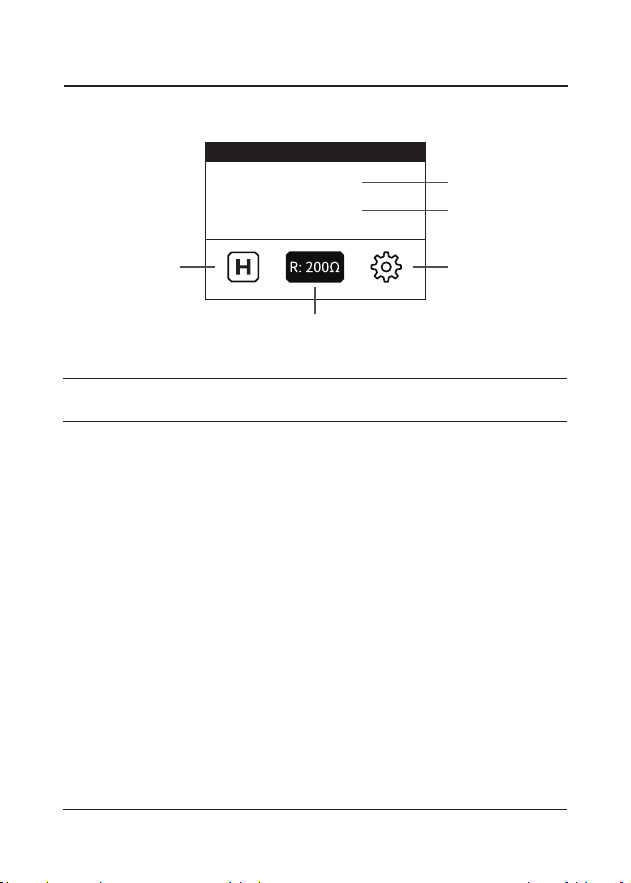
Resistance Interface Introduction
Internal Resistance Test
RESISTANCE
029.4Ω
07.49V
③
②
⑤
①
④
Internal Resistance
Value
Voltage Value
HOLD
RANGE
SETUP
Name
Displays the currently reading
value of the tested internal
resistance.
Displays the currently reading
value of the tested voltage.
Enables the system to retain
the reading.
Allows the user to manually
change the measurement
range when the range mode is
MANUAL.
Provides access to the
settings for result printing and
internal resistance reading
conguration.
Description
①
②
③
④
⑤
Item

30
1) Select RESISTANCE from the home screen and press [ENTER /
PRINT].
2) The system displays the internal resistance and voltage
readings of the tested battery.
If "-.-" appears, it means that the connection is not secure. In
this case, check the connection between the test cable and
the battery analyzer as well as the connection between the
clamps and the battery terminals. Restart the measurements
after ensuring the connections are proper.
If "OL" appears, it indicates that the measured value exceeds
the currently set measurement range. To resolve this issue, you
can try one of the following methods:
3) To hold the read value, select the HOLD option on the
Resistance interface. The system will display the held reading
value and show a conclusion with a PASS/WARN/FAILED
prompt.
NOTE:
The measurement range feature applies only to battery
resistance readings, with the default range set to 30mΩ.
The battery voltage measurement uses automatic
ranging mode, and the range cannot be changed.
To Perform Battery Resistance and Voltage Measurements
Enable the Automatic Range Mode: Navigate to SETUP >
RESISTANCE > AUTO/MANUAL > AUTOMATIC.
Manually Select the Resistance Range: Go to SETUP >
RESISTANCE > AUTO/MANUAL > MANUAL. Then, return to
the RESISTANCE interface, select the RANGE feature, and
press [ENTER/PRINT] to cycle through different ranges in
the order of 30mΩ > 300mΩ > 3Ω > 200Ω > 3mΩ. Once the
correct range is selected, the valid readings will be displayed.

31
4) To print the test result, select the SETUP softkey on the
Resistance interface, choose PRINT, and press [ENTER/PINT].
Select the feature of SETUP from the RESISTANCE interface,
and choose RESISTANCE, which enables you to customize
measurements threshold value, turn on or off the beep sound
and change the range mode.
Customize Measurement Thresholds
NOTE:
• The automatically held reading will remain even after
disconnecting the clamps from the tested battery. To
release the retained reading, press [ENTER/PRINT].
• The conclusion is determined based on preset
thresholds, which can be customized via the SETUP
interface. For details, refer to the part "Customize
Measurement Thresholds".
To Congure Settings
Warning:
To prevent possible electrical shock, re, or personal injury, do
not use the HOLD function to measure unknown potentials.
When HOLD is selected, the display does not change when a
different potential is measured.
Figure 4.5.2
THRESHOLD
0 mΩ
200000mΩ
00.00V
100.00V
12.00
000200
000200

32
1) Select THRESHOLD from the Resistance interface.
2) Press [ENTER/PRINT] to dene the lower limit of the
resistance tolerance range. Use the ▲/▼ keys to adjust the value
of the selected digit, and the ◀/▶ keys to move between digits.
Once the lower limit is set, press [ENTER/PRINT] to dene the
upper limit of the resistance tolerance range and the voltage
reading tolerance value in sequence.
When a tolerance range set is applied, the system compares
each resistance reading with the resistance reference in
the current threshold set. The resistance test interface then
displays the comparison conclusion: PASS (green), WARN
(yellow) and FAILED (red).
The system sets the xed lower and upper measurement
thresholds, along with a customizable tolerance range, for
battery resistance and voltage readings.
The device supports battery resistance reading from 0mΩ to
200Ω, and allows you to dene the lower and upper limit of
the tolerance range.
The device supports battery voltage reading from 0.00V to
±100.00V, and allows you to dene the tolerance value.
If the reading is between 0mΩ and the dened lower
tolerance limit, the comparison conclusion is PASS.
If the reading falls within the tolerance range, the comparison
conclusion is WARN, suggesting that the tested battery
requires further attention and increase in test frequency.
If the reading is between the dened upper tolerance limit
and 200Ω, the comparison conclusion is FAILED, suggesting
that the tested battery is potentially compromised and
should be further investigated.
At the same time, the device compares each stable voltage
reading with the lower voltage from the applied threshold
set.
If the reading is between the dened value and 100.00V, the
comparison result is PASS.
If the reading is between 0.00V and the dened value, the
comparison result is WARN.

33
1) Select BEEP from the Resistance interface.
2) You can choose from three options:
1) Select AUTO/MANUAL from the Resistance interface.
2) You can choose between AUTOMATIC and MANUAL.
NEVER: The device remains silent after presenting the
comparison conclusion.
PASS---ON: The device beeps when presenting the PASS
conclusion.
WARN/FAILED---ON: The device beeps when presenting the
WARN or FAILED conclusion.
AUTOMATIC: The system automatically switches to the
appropriate measurement range for the read resistance
values.
MANUAL: Users need to manually changes to the correct
measurement range for the read resistance values. For
details on manual operation, refer to Step 2 in the To Perform
Battery Resistance and Voltage Measurements section.
NOTE:
• If the resistance reading and the voltage measurement
have different conclusions, the system shows the
worse result on the display. For example, the resistance
indicates PASS but the voltage indicates WARN, the
product still shows WARN on the display.
• To measure only the battery's internal resistance, you
can set the tolerance value of the voltage test to 0 for
more precise resistance measurement conclusions.
Turn ON/OFF Beep Sound
Change the Range Mode

34
1) Select SEQUENCE from the home screen.
2) Select A--000 to start the batch test of the rst group.
3) If "OL" appears, it indicates the reading exceeds the current
measurement range, press the ▲/▼ keys to change the
measurement range till the valid reading is displayed.
4) Press [ENTER/PRINT], the reading value will be stored, and
the corresponding color of the comparison conclusion will be
shown in the column.
5) Press the ▶ key to move the cursor to the next column.
Connect the next battery via the test cables and the system
will automatically read the internal resistance and voltage.
6) To nish the test of the current group, press [ENTER/PRINT]
to save the current test data and go back to the previous
interface or press [EXIT] to leave the screen directly.
7) Select another group to continue the sequence test or press
[EXIT] to go back to the home screen.
Sequence Test is designed to measure the voltage and internal
resistance of batteries in batches. This function allows you to
perform batch testing of up to 500 batteries per group, with
support for up to 10 groups.
NOTE:
Automatic measurement range switching is not applied
during the sequence test.
NOTE:
The system allows you to update measured values. To
modify historical results, attach the clamps to the battery
terminals, use the ◀ /▶ keys to navigate to the desired
column and press [ENTER/PRINT] to save the new
readings.
Sequence Test

35
1) Select REVIEW from home screen and press [ENTER / PRINT].
2) Use the ▲/▼ keys to scroll through the list and select an option
to review or delete the results of the battery test, cranking test,
charging test, system test, and resistance test.
3) To view saved test results, press [ENTER/PRINT] after selection
from the REVIEW interface. Then, choose a piece of result data
from the time list to view the details. If you want to print the
result, press [ENTER/PRINT] again.
4) To delete the saved test results, press [ENTER/PRINT] after
selection from the REVIEW interface. Then, the system will
prompt you that the deletion succeeds.
The system automatically saves the latest ten test results from
previously performed tests. The REVIEW function allows you to
view or delete these saved results.
SECTION 5 REVIEW DATA
REVIEW
RESISTANCE
REVIEW BATTERY TEST
REVIEW CRANKING TEST
REVIEW CHARGING TEST
REVIEW SYSTEM TEST
REVIEW RESISTANCE TEST
DELETE BATTERY TEST
2025-03-26 15:12:19
2025-03-26 15:12:18
2025-03-26 15:12:17
2025-03-26 15:12:16
2025-03-26 15:12:15
2025-03-26 15:12:14
2025-03-26 15:12:13
Figure 5.1.1
Figure 5.1.2

36
NOTE:
Please exercise caution to delete saved test results. Once
you conrm deletion by pressing [ENTER/PRINT], all saved
results for the selected test type will be permanently
erased, and this action cannot be undone.
REVIEW
DELETE SUCCESSFULLY
Figure 5.1.3

37
NOTE:
To ensure the correct time is displayed, adjust the time
settings when using the device for the rst time.
The SYSTEM menu allows you to congure settings for resistance
test, time, language, and shutdown, as well as to view device
information.
SECTION 6 SYSTEM SETUP
1) Select SETUP from the home screen and press [ENTER /
PRINT].
2) Select RESISTANCE from the SETUP interface and press
[ENTER / PRINT]. Then you can dene settings of Threshold,
BEEP, Range Mode. For details, refer to the part of "To
Congure Settings" in the section of "Internal Resistance
Test".
1) Select SETUP from the home screen and press [ENTER /
PRINT].
2) Select Time from the SETUP interface and press [ENTER /
PRINT].
3) Use the ▲/▼ keys to adjust the value of the selected digit, and
the ◀ /▶ keys to move between digits, allowing you to modify
the year, month, date, hour, minute, and second from left to
right.
4) Press [ENTER/PRINT] to save and apply the settings. Press
[EXIT] to exit the interface without saving.
To Congure Resistance Test Settings:
To Adjust the Displayed Time:

38
1) Select SETUP from the home screen and press [ENTER /
PRINT].
2) Select Language from the SETUP interface and press [ENTER
/ PRINT].
3) Use the arrow keys to navigate to and select your preferred
language.
4) Press [ENTER/PRINT] to save and apply the settings. Press
[EXIT] to exit the interface without saving.
1) Select SETUP from the home screen and press [ENTER /
PRINT].
2) Select SHUTDOWN from the SETUP interface and press
[ENTER / PRINT].
3) Use the ▲/▼ keys to scroll through the options and select your
preferred interval.
To Set up the Automatic Shutdown Interval:
NEVER: The device stays ON until its built-in batteries are
depleted and it is no longer connected to any tested battery.
1 MINUTE: The device will automatically shut down one
minute after you disconnect it from the tested battery and
perform no operation on this tool.
5 MINUTES: The device will automatically shut down ve
minutes after you disconnect it from the tested battery and
perform no operation on this tool.
10 MINUTES: The device will automatically shut down ten
minutes after you disconnect it from the tested battery and
perform no operation on this tool.
15 MINUTES: The device will automatically shut down fteen
minutes after you disconnect it from the tested battery and
perform no operation on this tool.
To Change the System Language:

39
1) Select SETUP from the home screen and press [ENTER /
PRINT].
2) Select ABOUT from the SETUP interface and press [ENTER /
PRINT].
3) You can view the information of hardware version, software
version, serial number and register code.
4) Press [ENTER/PRINT] to save and apply the settings. Press
[EXIT] to exit the interface without saving.
To View More Information about the Device

40
A computer with Windows XP/7/8/10 system is required to
update the device.
1) Go to www.topdon.com/products/BT600-Plus, click
"Download", and download the update tool to your computer.
2) Install the update tool and log in.
3) Connect the analyzer to the computer via the USB cable.
4) Register the analyzer, the information of the analyzer will
be shown on the My Device interface. Conrm the serial
number is correct. (This step is not necessary if you've already
registered the device.)
5) Select "Upgrade", the newest rmware version will show
up. Click "Upgrade", the software will start to upgrade the
analyzer. Wait until the prompt indicates success.
SECTION 7 UPDATE
NOTE:
If you don't have an account, register an account with your
email address rst.
NOTE:
The device will automatically initialize the rst time it is
used after the upgrade.
41
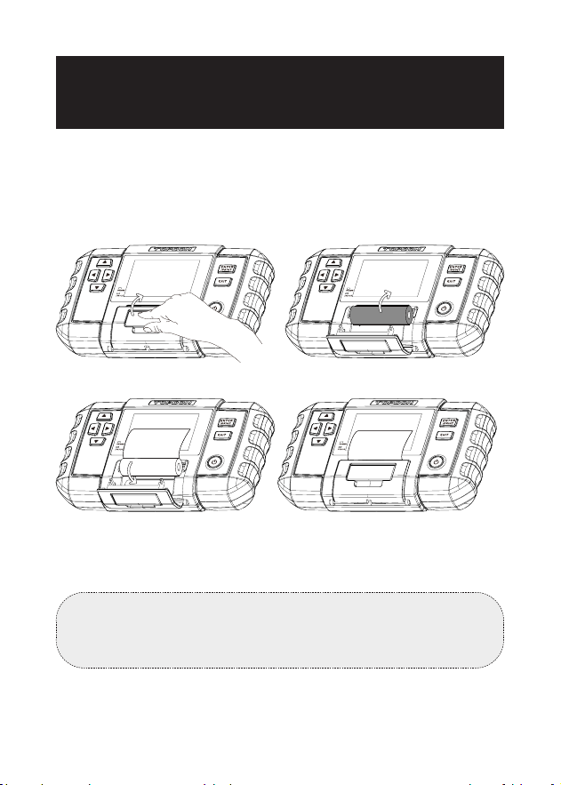
SECTION 8
REPLACE PRINTER PAPER
This battery analyzer comes with three rolls of printer paper, of
which one is installed in the analyzer and the other four are in
the box. Please follow the following gures below to replace the
paper roll.
NOTE:
The direction of the printer paper must be followed in order,
otherwise it will not be able to print the content.
Figure 8.1.1
Figure 8.1.3
Figure 8.1.2
Figure 8.1.4

42
SECTION 9
TECHNICAL SPECIFICATIONS
Working Temperature
Storage TemperatureVoltage
Test Range (DC)
Voltage Test Accuracy
Internal Resistance Test Range
Internal Resistance Test
Accuracy
Dimensions
Cable Length
Rechargeable Battery Capacity
0°C~50°C (32°F~122°F)
-20°C~70°C (-4°F~158°F)
0V to ±100V
±0.5%
0mΩ to 200Ω
±1%
218 x 134 x 57mm (8.58 x 5.27 x
2.24"")
1800mm (70.9"")
1000mm (39.37'')
2600 mAh per cell × 2

43
Q: Can the BT600 Plus test the battery installed in the vehicle?
A: Yes, it supports in-vehicle and out-of-vehicle testing.
Q: Are the test results accurate?
A: Yes. Our BT600 Plus features advanced conductance
detection, able to give you accurate test results in seconds.
Q: What batteries can the BT600 Plus work on?
A: It works on 6V, 12V and 24V regular ooded, AGM Flat plate,
AGM Spiral, GEL and Deep Cycle batteries, with CCA between
100 to 2000.
Q: Is the BT600 Plus designed with any built-in protections?
A: Yes. It offers extra-safe Reverse Polarity protection. It offers
easy operations even if you're new to battery testing.
Q: How do I conrm if my vehicle battery is bad or good?
A: The battery analyzer will display SOH (State of Health), SOC
(State of Charge), CCA (Cold Cranking Ampere), Voltage,
Internal Resistance, and Rating, with an intuitive test result of
"GOOD", "NORMAL" or "BAD" for your reference. If the internal
resistance is too large, it indicates a broken battery.
Q: Can this battery analyzer estimate the remaining capacity of
my battery?
A: Yes. The battery analyzer will display SOC (State of Charge)
to express as a percentage of your battery's rated capacity, a
measure of its condition to assess the potential energy.
Note that a decent SOC (State of Charge) doesn't mean the
battery is in good condition. Be sure to refer to your battery's
actual CCA Value and Internal Resistance for further analysis.
Q: Can this device test internal resistance independently? What
types of batteries does it support?
A: Yes. It supports lead-acid batteries, lithium batteries and dry
batteries.
SECTION 10 FAQ

44
TOPDON's One-Year Limited Warranty
The TOPDON Company warrants to its original purchaser that
TOPDON products will be free from defects in material and
workmanship for 12 months from the date of purchase (Warranty
Period). For the defects reported during the Warranty Period,
TOPDON will, according to its technical support analysis and
conrmation, either repair or replace the defective part or
product.
If there is any conict between the TOPDON warranty policy and
local laws, the local laws shall prevail.
This limited warranty is void under the following conditions:
• Misused, disassembled, altered or repaired by unauthorized
stores or technicians.
• Careless handling and/or improper operation.
Notice: All information in this manual is based on the latest
information available at the time of publication, and no warranty
can be made for its accuracy or completeness.
TOPDON reserves the right to make changes at any time
without notice.
SECTION 11 WARRANTY
Q: Why does the device produce a clicking sound during the test
process?
A: The clicking sound is caused by the device switching circuits
during testing. This is a normal occurrence and does not
indicate any malfunction.

45
FCC Statement
This device complies with Part 15 of the FCC Rules. Operation is
subject to the following two conditions:
(1) this device may not cause harmful interference, and
(2) this device must accept any interference received, including
interference that may cause undesired operation.
COMPLIANCE INFORMATION

+86-755-21612590 (China) I +1-833-629-4832 (North America) I +34 930 038 094 (Europe)
WWW.TOPDON.COM
@TOPDONOFFICIAL
@TOPDON_OFFICIAL