USER MANUALS\86772_ADDENDA_USER MANUAL_PC(L)82_AMB_WALL SERIES_GLS FRT DRS_PASTRY CASE
REV L DATE: 07/25/2023
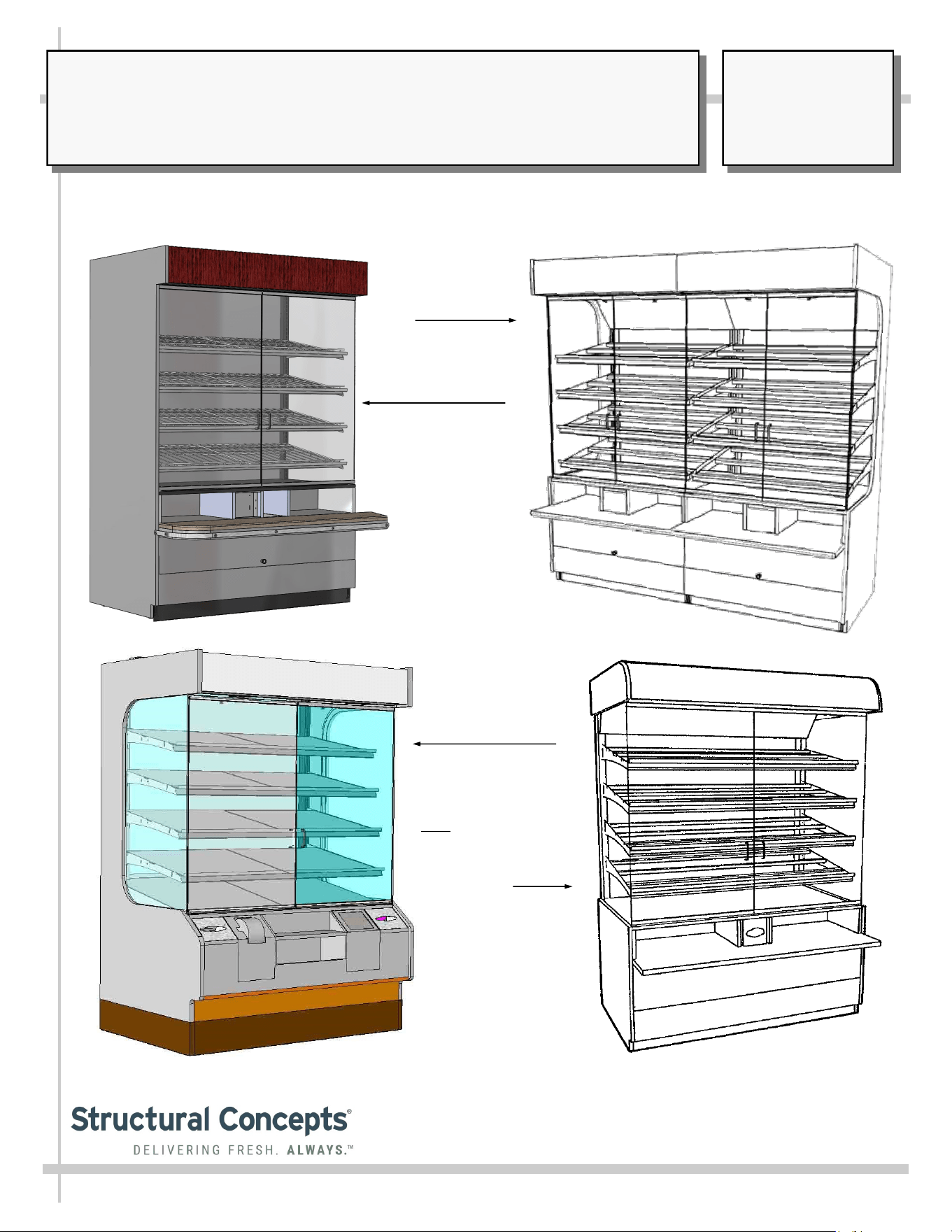
MODEL PC “WALL SERIES” CASES*
> AMBIENT PASTRY UNITS > TISSUE/BAG DISPENSERS > GLASS HINGED FRONT DOORS
PC5682
PC3982.6025
Lineup
PC5682.6744 / Wire
Shelving Racks /
Waste Bin / Solid
Surface Front Shelf
* This Manual Pertains To Models PC3982, PC5682, PC5682.5584A, PC5682.6744, PC5682.6769, PC7482 And Other CDRs.
PC5682.5584 / Solid
Shelving / Waste Bin /
Tissue Box Holders /
Front Shelf
Note: Unit is Similar
to PC5682.6769.
SCC P/N
86772
USER
MANUAL
ADDENDA
®
READ AND SAVE THESE INSTRUCTIONS
Structural Concepts Corp. ∙ 888 E. Porter Rd ∙ Muskegon, MI 49441 Phone: 231.798.8888 Fax: 231.798.4960 ∙ www.structuralconcepts.com
TABLE OF CONTENTS
2
OVERVIEW / TYPE / COMPLIANCE / WARNINGS / PRECAUTIONS / WIRING / PLUGS ..………...
INSTALLATION / POSITIONING AND ALIGNING / ADJUSTING LEVELERS .…………...…………..
INSTALLATION, CONTINUED: BOLTING ADJOINED UNITS …………………………………………..
INSTALLATION, CONTINUED: PACKAGE LEDGE ADJOINING / HEADER ADJOINMENT /
MIRROR ………………………………………………………………………………………………...
ELECTRICAL FUNDAMENTALS: FIELD WIRED MODELS ……………………………………………..
ELECTRICAL FUNDAMENTALS, CONTINUED: PLUG/CORD UNITS ………………………………...
ELECTRICAL FUNDAMENTALS, CONTINUED: T-8 / FLUORESCENT BULBS ……………………..
ELECTRICAL FUNDAMENTALS, CONTINUED: LED LAMPS ………………………………………….
ELECTRICAL FUNDAMENTALS, CONTINUED: LIGHT SWITCH, RECEPTACLE AND PLUGS ….
MAINTENANCE: SHELF ASSEMBLY REMOVAL ………………………………………………………...
MAINTENANCE, CONTINUED: FRONT FLIP-UP DOOR / WASTE BIN ACCESS
(CERTAIN MODELS ONLY) …..……………………………………………………………………..
MAINTENANCE, CONTINUED: AXIAL EXHAUST FANS / FLIP-DOWN WASTE BIN & TISSUE
BIN ACCESS …………………………………………………………………………………………...
GENERAL CLEANING ………………………………………………………………………………………...
ENGINEERED (SYNTHETIC) QUARTZ CARE AND MAINTENANCE ………………………………….
TROUBLESHOOTING …………………………………………………………………………………………
SERIAL LABEL & LOCATION / INFORMATION LISTED / ADD’L TECH INFO & SERVICE .……....
TECHNICAL SERVICE CONTACT INFORMATION / WARRANTY INFORMATION ...…………...…..
3
4
5
6
7
8
9
10
11
12
13
14
15
16
17
18
19
3
OVERVIEW
• These Structural Concepts cases should be installed and
operated according to these instructions to ensure proper
performance. Improper use will void warranty.
• This unit is designed to display of products in ambient
store conditions with a max. temperature of 80 °F (27 °C) .
COMPLIANCE
• Performance issues when in violation of applicable NEC,
federal, state or local electrical codes are not covered by
warranty. See below.
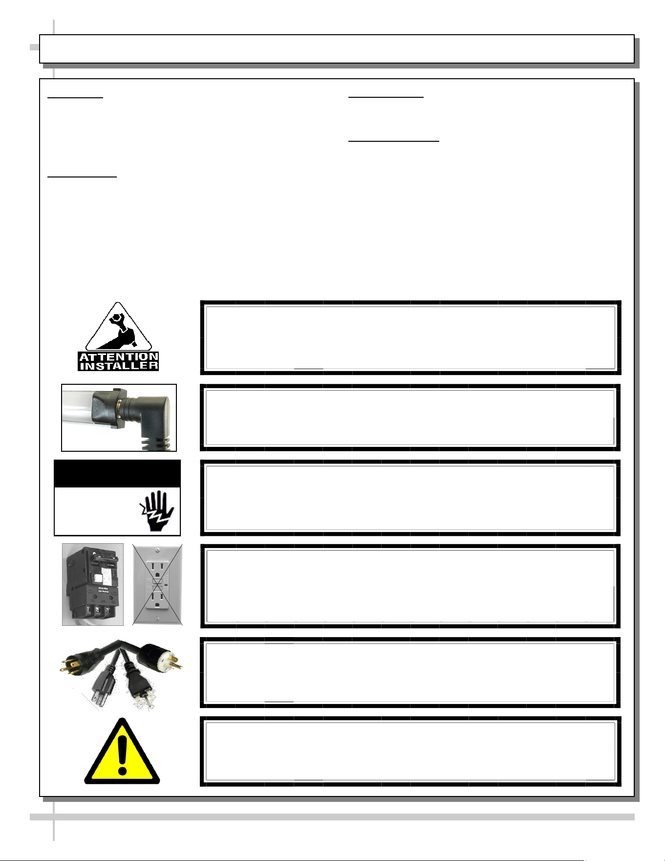
WARNING
Risk of electric shock.
Disconnect ALL ELECTRICAL SOURCES before servicing.
WARNING
ELECTRICAL
HAZARD
COMPLIANCE
This equipment MUST be installed in compliance with all applicable NEC,
federal, state and local electrical and plumbing codes.
PRECAUTIONS
• Following are important precautions to prevent damage
to unit or merchandise. Read carefully!
WIRING DIAGRAM
• Each case has its own wiring diagram folded and in its
own packet. It may be placed near ballast box, field
wiring box, raceway cover, or other related location.
CAUTION! POWER CORD AND PLUG MAINTENANCE
Risk of electric shock. If cord or plug becomes damaged,
replace only with cord and plug of same type.
CAUTION! GFCI BREAKER USE REQUIREMENT
If N.E.C. (National Electric Code) or your local code
requires GFCI (Ground Fault Circuit Interrupter) protection,
you MUST use a GFCI breaker in lieu of a GFCI receptacle.
OVERVIEW / COMPLIANCE / WARNINGS / PRECAUTIONS / WIRING DIAGRAM / CORDS & PLUGS
CAUTION! LAMP REPLACEMENT GUIDELINES
If LED lamps are used, they must be size, shape and overall design.
Any replacements must meet factory specifications.
WARNING: This product can expose you to chemicals, including
Urethane (Ethyl Carbamate), which are known to the state of
California to cause cancer and birth defects or other reproductive
harm. For more information go to P65Warnings.ca.gov.
INSTALLATION / POSITIONING AND ALIGNING / ADJUSTING LEVELERS
4
Slide
Skid
Out
Support
required to
prevent
tipping.
A
B
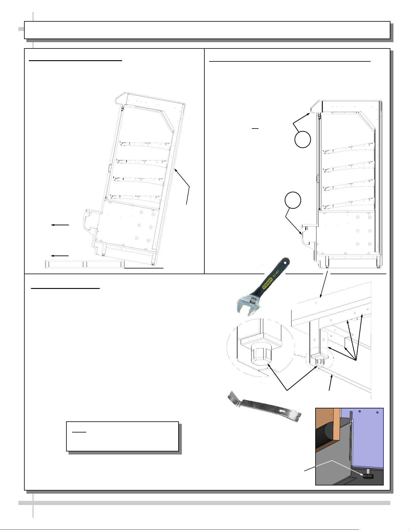
1. Remove Unit From Skid
Caution! case must always remain supported or
center of gravity will allow case to fall. Slide unit to
rear of skid and tip backward off skid.
Pry Bar
Base
Frame
Leveler
Adjustable
Wrench
Toe-Kick
3. Adjust Levelers
• After case is in proper position, adjust case so it
is level and plumb (see illustration at right).
• You may need to remove front and/or rear
Toe-Kick to access levelers.
• Use adjustable wrench to adjust leveler.
• Depending upon case weight it may be necessary
to use a Pry Bar to accomplish this task.
• Do not use Pry Bar on Toe-Kick as it may buckle.
• Do not use Pry Bar on End Panel as it may chip.
• Use Pry Bar ONLY on Base Frame to avoid
damaging case.
• See illustration and photos at right.
2. Position & Align Case Alongside Others
• Before adjusting levelers, make certain that the
case is in proper position and, if required, aligned
with adjoining case(s). Line up areas A & B as
shown below.
• This may require the
repositioning of the
case you are
installing or the
already positioned
cases
Alternate Leveler Style
Note: Illustrations Shown May Not
Exactly Reflect Every Feature or
Option of Your Particular Case
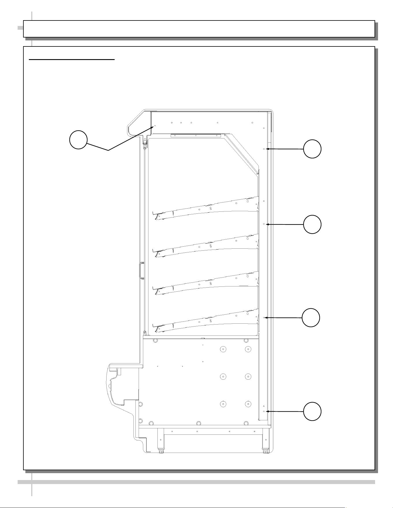
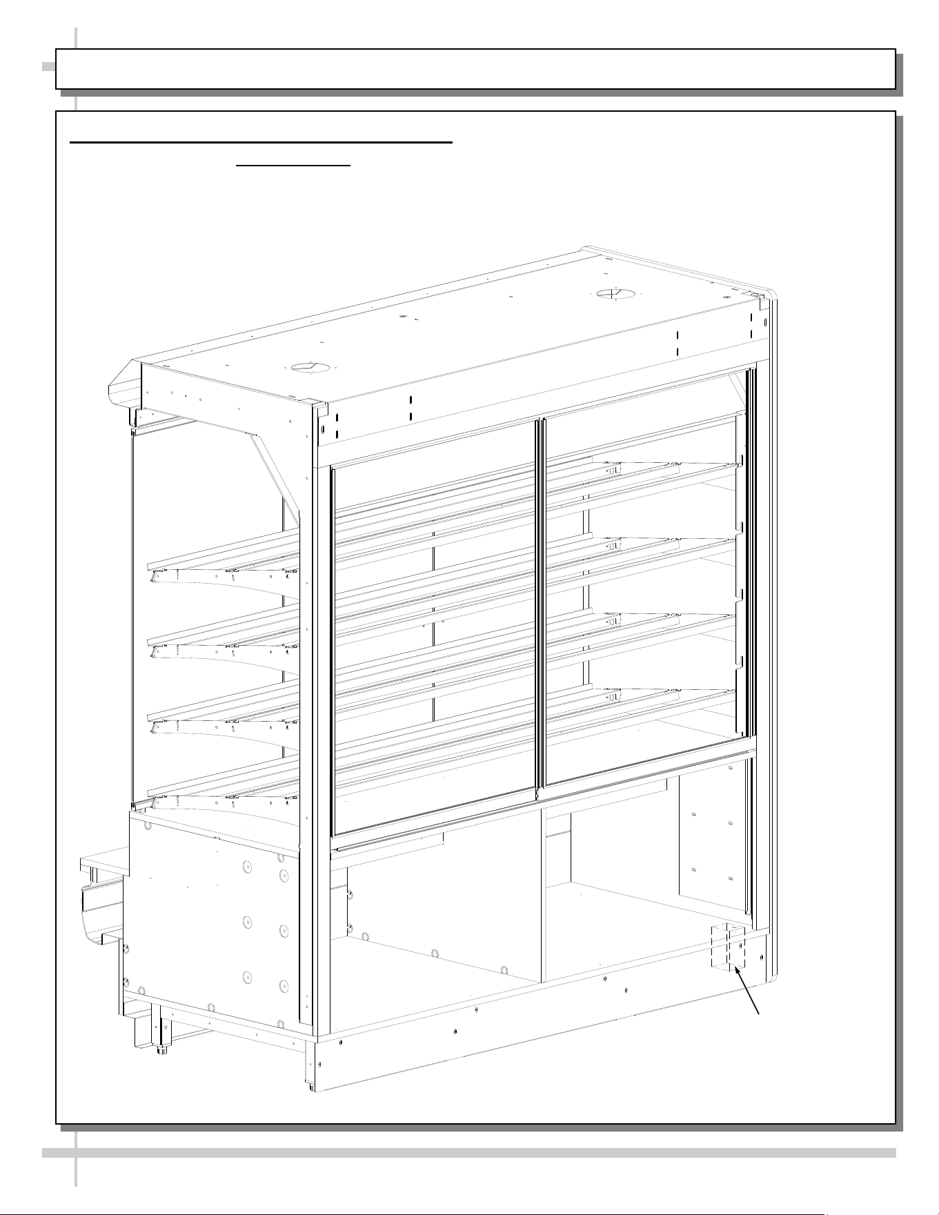
4. Bolting Adjoined Units
• View shown is after removal of end panel.
• Units are bolted together at locations shown.
• Eight 1/4-20 x 2 1/2” bolts & nuts provided.
5
INSTALLATION, CONTINUED: BOLTING ADJOINED UNITS
1
2
3
4
5
INSTALLATION, CONTINUED: PACKAGE LEDGE ADJOINING / HEADER ADJOINMENT / MIRROR
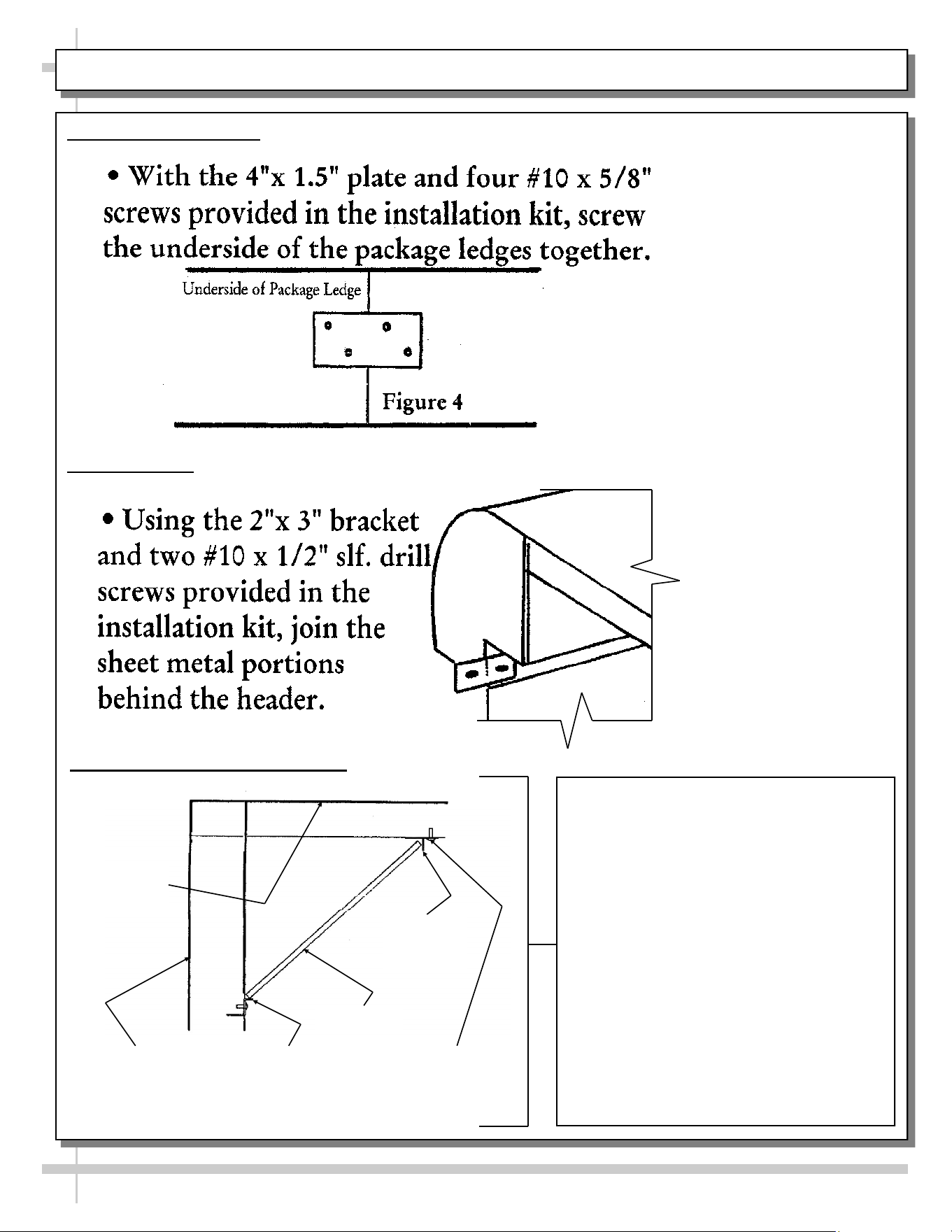
5. Join Package Ledges
6. Join Headers
CAREFULLY FOLLOW THESE MIRROR
INSTALLATION INSTRUCTIONS:
1. TO MAINTAIN SAFETY, TWO PEOPLE
SHOULD PERFORM THIS STEP- BY-
STEP PROCEDURE.
2. LOOSEN UPPER MIRROR RETAINING
SCREWS.
3. PLACE LOWER END OF MIRROR
AGAINST LOWER MIRROR CHANNEL.
4. ROTATE UPPER MIRROR CHANNEL
INTO PLACE [BEHIND UPPER MIRROR
CHANNEL].
5. AFTER CHECKING THAT MIRROR IS
SECURE, TIGHTEN UPPER MIRROR
RETAINING SCREWS.
6. RE-CHECK THAT MIRROR IS
SECURELY HELD IN PLACE AND
WILL NOT COME LOOSE.
6
UPPER MIRROR
RETAINING
SCREWS
LOWER
MIRROR
CHANNEL
MIRROR
REAR OF
CASE
TOP OF
CASE
UPPER
MIRROR
7. Mirror Installation & Retrofitting
6
7
ELECTRICAL FUNDAMENTALS: FIELD WIRED MODELS
1. Electrical Fundamentals (Field Wired Models)
Electrical access is at lower-right side of case (when facing rear of case).
• 120V single phase leads provided.
• Model PC7485.4175A is shown below.
Field Wiring
Box
8
ELECTRICAL FUNDAMENTALS, CONTINUED: PLUG/CORD UNITS
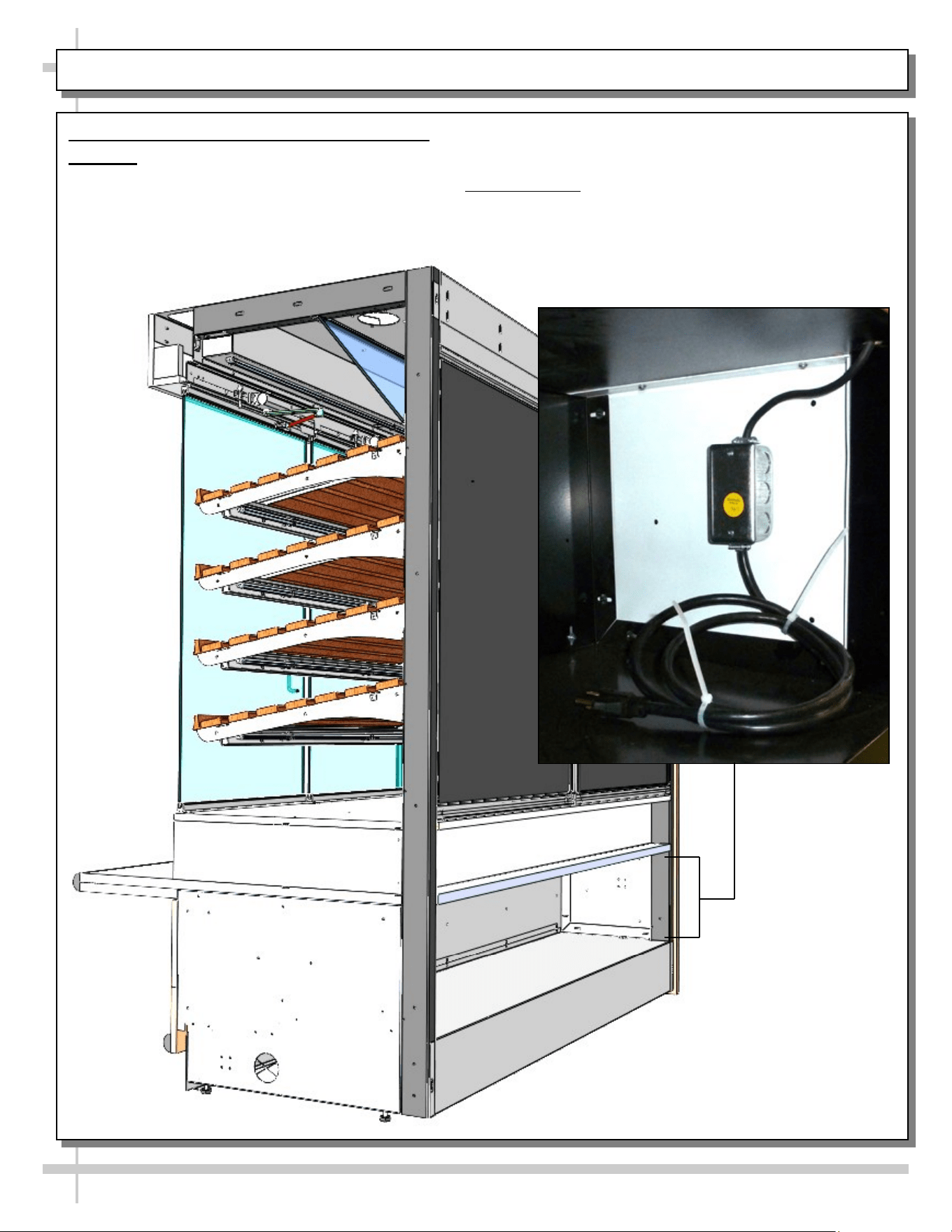
2. Electrical Fundamentals (Plug/Cord Units)
Warning: Disconnect power before providing maintenance/service to unit.
On units with plug/cord setup, electrical access is at lower-right side of case (when facing rear of case).
• J-Box and 120V single phase cord and plug is provided.
• Model PC7482.5886D is shown below.
9
ELECTRICAL FUNDAMENTALS, CONTINUED: T-8 / FLUORESCENT BULBS
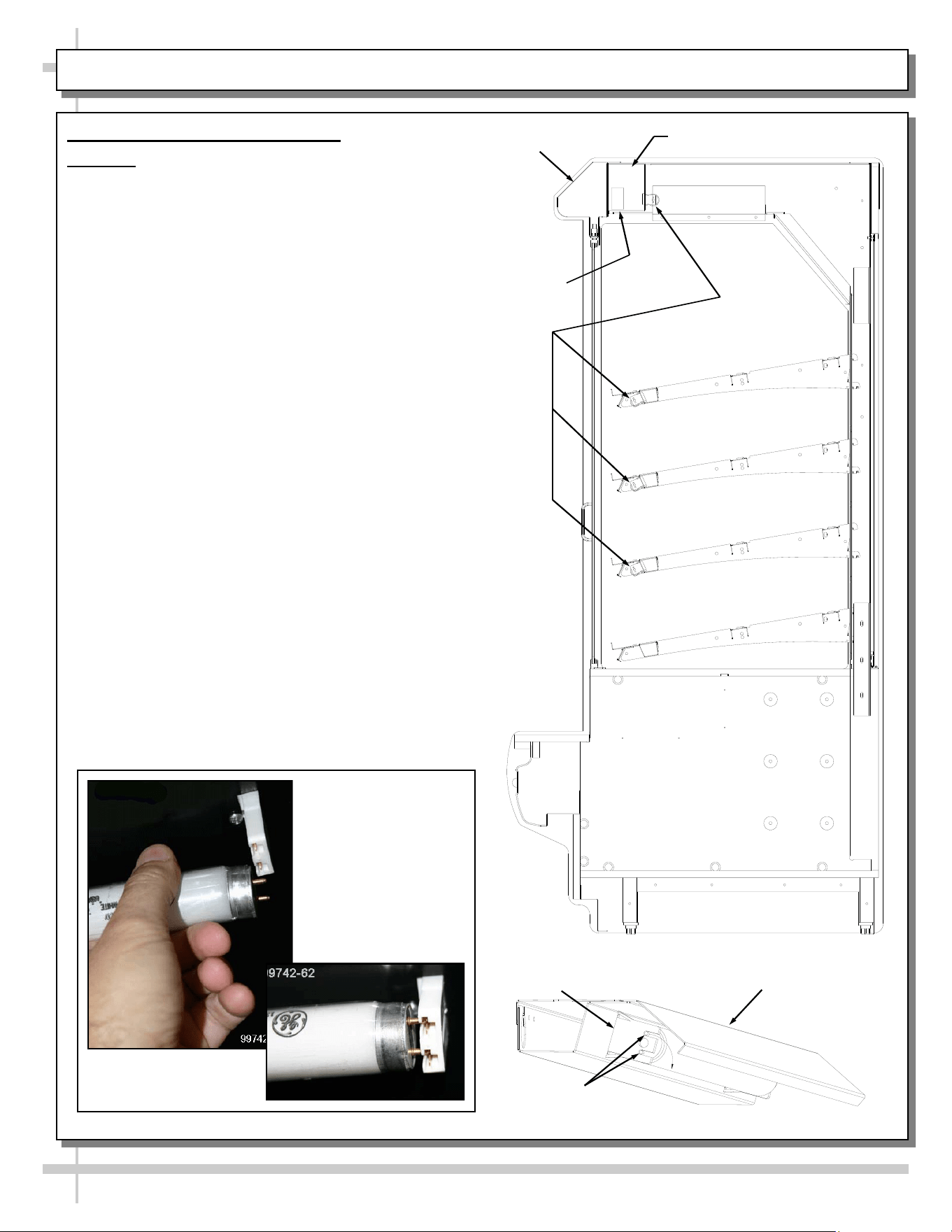
3. T-8 / Fluorescent Light Fixtures
Warning: Disconnect power before providing
maintenance/service to unit.
Ballast Access/Removal
Assembly or disassembly and servicing to be
accomplished by licensed electrical contractor.
• The light ballast is located inside the header.
• Unplug light harness (plug and receptacles). See
next page for illustration.
• Remove the header electrical box.
• Remove florescent bulb.
• Remove screws securing the ballast box to
the header top.
• Remove wire nuts from electrical leads.
• Some models have quick disconnect
releases from the wire harness.
• Remove nuts from ballast end mounting flanges.
Light fixtures are located on the underside of each
shelf assembly and at the top inside of case.
Removal of lamp:
• Rotate lamp (1/4 turn) so that pins are aligned in
slots and remove bulb.
Installation of lamp:
• Align pins with slot.
• Insert pins into socket and rotate 1/4 turn to
secure pin contacts in socket.
Lamp Pins
Light Socket
Light Fixture
Ballast
Header
Lights
Electrical Box, Header
View of Removal /
Install of Standard
Fluorescent
Light Fixtures
10
ELECTRICAL FUNDAMENTALS, CONTINUED: LED LAMPS
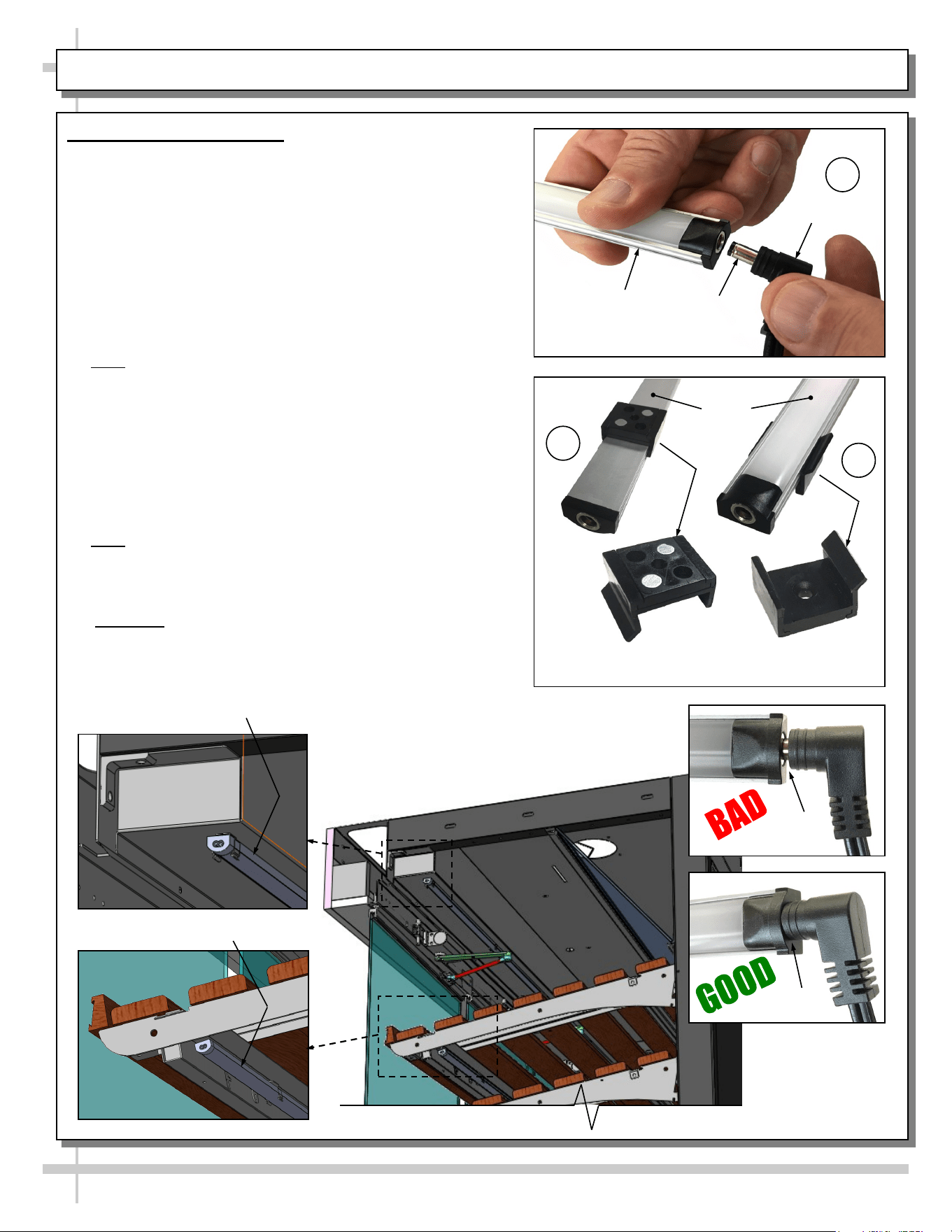
4. LED Style Light Fixtures
Removal of Faulty LED Lights:
• Contact Structural Concepts’ Technical Service
Department for replacement LED lights.
• Turn off LED light switch.
• To remove faulty LED light, follow these steps:
A. Disconnect plug from LED light.
B. Using both hands, grasp LED light assembly (with its
magnetic mounting clips). Pull downward and off its
shelf (or header).
C. Remove magnetic mounting clips from LED light by
pressing against flange part of clip with thumb.
>> Note: Mounting clips MAY be riveted to shelf or header.
In such instances, simply remove LED light from mounting
clips by pressing against flange part of clips with thumb.
Replacement of LED lights:
• Attach magnetic mounting clips onto LED light.
• Adjust magnetic mounting clips so they are equally
spaced on LED light.
• Reattach LED light assembly to its shelf/header.
• Position properly in shelf/header.
>> Note: If mounting clips are riveted to shelf (or header),
attach by placing LED in base of clip and then snapping into
clip at FLANGE SIDE.
• Press plug’s barrel-shaped insert deep into LED light.
• Important: If plug is not inserted ALL THE WAY IN the
LED light’s orifice, the light may not energize. See
“BAD” vs. “GOOD” insertion illustrations below-right.
• Turn LED light switch back on.
Magnetic Mounting
Clip View #2
LED
Lights
B
A
Plug
Barrel
Shaped
Insert
LED
Light
C
Magnetic Mounting
Clip View #1
No Gap
Gap
Header LED Light
Shelving LED Light
11
ELECTRICAL FUNDAMENTALS, CONTINUED: LIGHT SWITCH, RECEPTACLE AND PLUGS
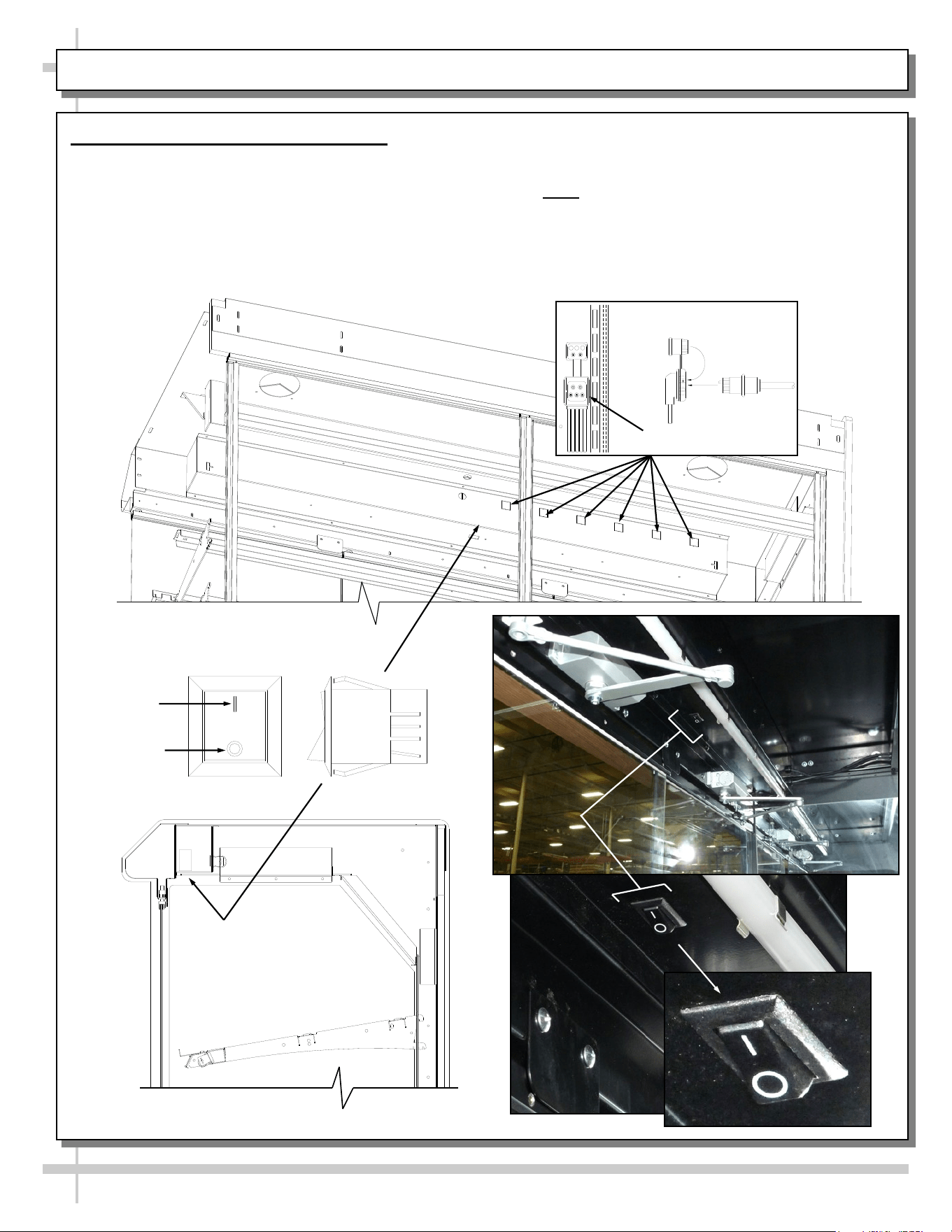
5. Light Switch, Receptacles and Plugs
• Depending upon model, light switch may be located
on electrical box (top center forward of bulbs). All of
the lights should come on at the same time. First
time lighting may require a short warm-up period.
• Initial dim or flickering bulbs is normal. If lights do
not turn on, check all of the raceway plugs.
Cap
Plug
Receptacle
OFF
ON
Rocker Switch
• Lighting is in series so all lights must be
plugged in or receptacles capped for the
case to light.
• Note: Illustration below may not reflect every
feature or option of your particular case.
MAINTENANCE: SHELF ASSEMBLY REMOVAL
12
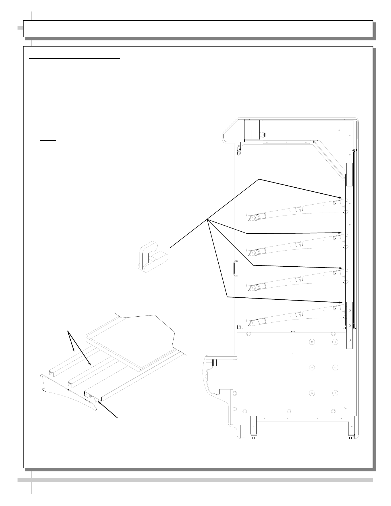
1. Shelf Assembly Removal
• For lighted shelving, unplug the light cord.
• Light shelf cord harnesses plug into the
back side of the header electrical box.
• Detach cord from the rear frame support.
• Slide light assembly back to unlock, then rotate
up to separate from brackets.
• Slide rear support back to unlock and rotate up
to separate from brackets.
• Remove brackets.
• Note: It may be necessary to remove the
nylon shipping bracket retainers. Pliers will
be required to accomplish this task.
Bracket
Retainers
Shelf Light
Shelf Supports
Shelf Bracket
Tray (Optional)
Separately
Purchased
MAINTENANCE, CONT.: FRONT FLIP-UP DOOR / WASTE BIN ACCESS (CERTAIN MODELS ONLY)
13
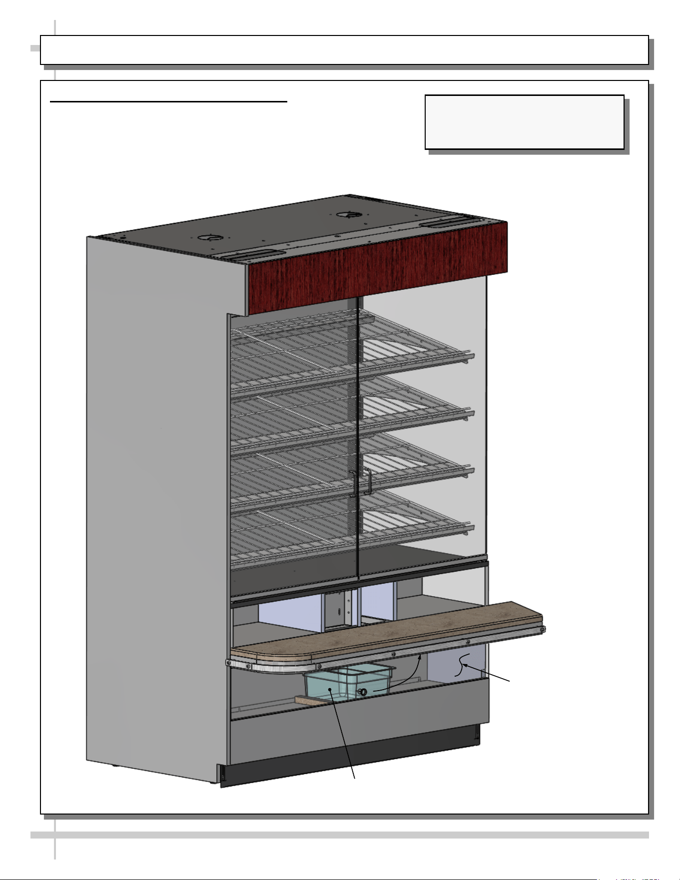
2. Front Flip-Up Door / Waste Bin Access
• Front flip-up door allows access to waste bin
(and entire waste bin area).
• This feature is only on certain models.
• See illustration below.
Front Flip-Up Door Is
Shown Transparent
For Illustrative
Purposes Only
Waste Bin
Model PC5682.6744 Shown May
Not Exactly Reflect Every Feature or
Option of Your Particular Case.
MAINTENANCE, CONT.: AXIAL EXHAUST FANS / FLIP-DOWN WASTE BIN & TISSUE BIN ACCESS
14
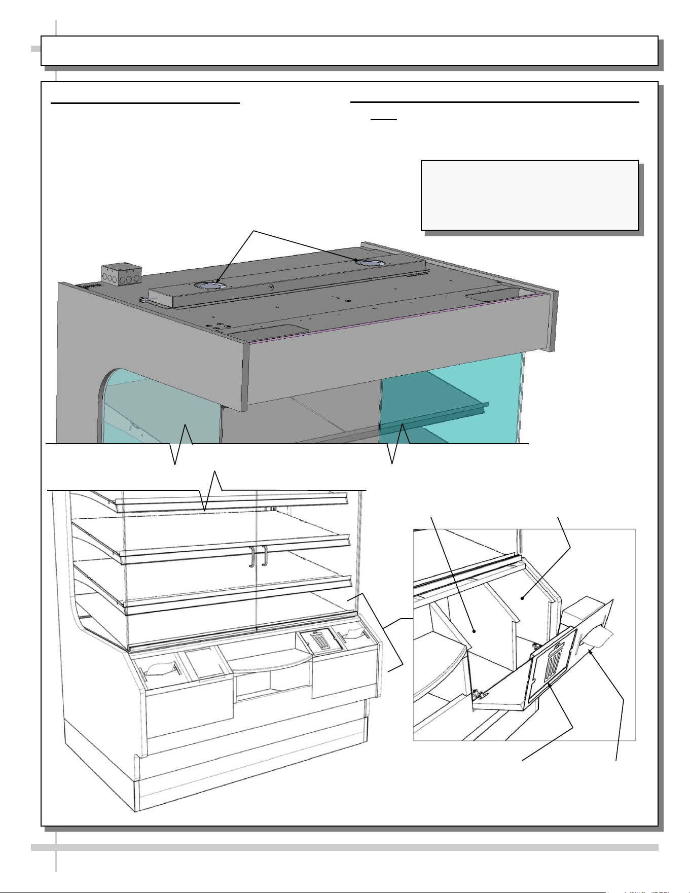
3. Axial Exhaust Fans (Optional)
• Axial exhaust fans help to keep inside air
temperature from heating up.
• These fans are not on all cases.
• See illustrations below.
Features of Models PC5682.5584A and
PC5682.6769 Are Shown. They May
Not Exactly Reflect Every Feature or
Option of Your Particular Case.
Waste Bin
Location
Waste Bin Door
Shown Lowered
Tissue Box
Holder Shown
Lowered
Tissue Box
Location
Axial Fans (Optional)
4. Front Flip-Down Waste Bin/Tissue Box Access
• Note: These features are not on all cases.
• See illustrations below.
15
GENERAL CLEANING
FREQUENCY INSTRUCTIONS
Daily End Panels, Front Panel, Toe-Kicks, Etc.: Wipe off all surfaces with warm water and
mild soap solution and non-abrasive cloth.
Daily Wood, Laminate and Painted Surfaces (Including Shelves): Clean with mild soap
and water solution and a soft cloth.
Daily ENGINEERED (SYNTHETIC) QUARTZ: See next page.
Daily Glass Doors and Angled Internal Mirror: Clean glass door surfaces with a household
or commercial glass cleaner. Wipe dry with paper towel or soft cloth.
Daily Wire Shelving Racks:
• Wipe down with warm water and mild soap solution and non-abrasive cloth.
• For hardened residue, remove from case. Submerse in warm soapy water. Use
soft-bristled brush to dislodge caked on and hardened residue. Rinse. Wipe dry with
paper towel or soft cloth.
Weekly Napkin Dispenser / Waste Bin Area:
• Napkin dispenser: Remove napkin box. Wipe down areas with warm water and mild
soap solution and non-abrasive cloth. Wipe dry with paper towel or soft cloth.
• Waste bin area: Flip-up door, reach in and remove waste bin. Wipe down waste bin
area with warm water and mild soap solution and non-abrasive cloth. Wipe dry with
paper towel or soft cloth.
• See FRONT FLIP-UP DOOR / WASTE BIN ACCESS (CERTAIN MODELS ONLY)
section in this manual for illustration.
Quarterly Under Case Cleaning: Remove front toe-kicks (screw removal is required). Use a
broom or vacuum to remove dust and dirt that may collect at underside of case.
Quarterly Axial Fans Atop Case (Optional) / Authorized Personnel Only
• Caution! Disconnect power to unit before proceeding!
• Wipe down areas around fan housing that can collect dust and debris.
• If fan design allows, wipe down fan blades that can collect dust and debris.
• Restore power to unit after performing this cleaning process.
16
ENGINEERED (SYNTHETIC) QUARTZ CARE AND MAINTENANCE
Engineered
Quartz
Overview
Engineered (Synthetic) Quartz Overview:
• Engineered (synthetic) quartz is a ‘man-made’ product. It is sometimes called “engineered stone.” It is made from
crushed quartz particles bonded with polyester, styrene, resin, pigments and tert-butyl peroxybenzoate.
• It is non-porous, mold and mildew-resistant, and impervious to odor-causing bacteria.
• Slabs are specifically sized. Engineered quartz contains a maximum of 94% mineral quartz (though percentages
vary). Engineered quartz is extremely resistant to damaging chemicals.
• There are many engineered (synthetic) quartz brands. These include Caesarstone, Cambria, Compac, Corian, Daltile
ONE, Granite HanStone, Transformations, Kowalski, LG Hausys, LG Viatera, Lunastone, Marble.com, MSI Q, Okite,
Pental, Polarstone, Pompeii, Samsung, Sensa, Silestone, Stone Italiana, Vadara, Vena & Vicostone.
Routine
Care
For Daily, Routine Care and Cleaning:
Engineered (synthetic) quartz require very little maintenance. Simply wipe the surface with neutral pH balanced
household detergent and warm water solution with soft sponge or microfiber cloth to maintain its shine.
• To prevent fading, keep from harsh, direct sunlight for long periods of time.
• General cleaners: use neutral pH balanced household detergent and warm water (4 cups of water/1 teaspoon of
detergent). Or isopropyl alcohol (aka rubbing alcohol). Or use any general, all-purpose cleaner, glass cleaner or Pine
Sol. Or use Clorox Wet Wipes (as they contain no bleach or and are soft). After cleaning, thoroughly rinse with water
and dry with clean cloth to prevent water spots from forming.
• Specifically designed cleaners for manufactured quartz: Black Diamond Stoneworks Granite Counter Cleaner,
Caldrea Countertop Spray, Clark’s Natural Stone Spray Cleaner, Granite Gold, Simple Green, Park & Bailey Granite
& Stone Cleaner, Seventh Generation Granite & Stone Cleaner, Stone Care Quartz Clean & Shine, Stone Pro Quartz
Countertop Cleaner, Weiman Quartz Countertop Cleaner and Polish.
Difficult
Spills
For Difficult Spills, Stains and Spots:
• Thoroughly clean with warm water and neutral pH detergent (mixture detailed above) before pursuing next steps.
• Clean up high staining liquids such as coffee, tea, fruit juice, lemon juice, vinegar, wine and tomato juice right away.
Use warm water and neutral pH detergent to do so. After cleaning, thoroughly rinse with water and dry.
• For residues that harden as they dry (food, gum, nail polish, and paint), place wet cloth or paper towel over residue
for 10 minutes (to soften its properties); then gently scrape off residue by using a plastic putty knife or plastic scraper;
avoid metal blades or scrapers if possible; then clean using warm water and soap. If you must use metal razor blade
or scraper, remove gray marks with soap and water. Thoroughly rinse with water and dry to prevent water spots.
• Difficult spots may need to be treated with solutions/chemicals BEYOND warm water and neutral pH detergents: A.
Water/white vinegar mixture: 2 cups of water with 1 tablespoon of white vinegar in spray bottle; spray surface; allow
solution to sit for 2 minutes; wipe off with soft cloth or sponge. B. Soft Scrub Liquid Gel: Apply gel to cloth or sponge
(not directly to quartz surface); wipe the area in a circular motion; repeat until spot is removed. C. Goo Gone
adhesive remover (for sticky residue). Thoroughly rinse the surface with water and wipe dry to prevent water spots.
• Water stain removal: 1 part vinegar + 3 parts baking soda in warm water. Dip cloth in mixture and thoroughly soak
stain. Leave for 5-10 minutes; then scrub area with soft brush. Rinse with water and dry with clean cloth.
Extreme
Heat
Protection
Extreme Heat Protection:
• Engineered quartz is extremely resistant to heat, and can withstand moderately high temperatures for brief periods of
time without being damaged.
• Engineered quartz CAN BE damaged by sudden and extreme temperature changes; thus, use a trivet or a hot pad to
protect its surface from hot pans, hot dishes or small appliances that may reach high temperatures.
Chemicals
To
Avoid
Chemicals To Avoid:
• Nail polish remover (acetone), oil soaps, and furniture cleaners or paint strippers that contain trichloroethane or
methylene chloride.
• Chemicals with an alkaline level of pH >10 (oven cleaners, chloring bleach, lacquer thinner, ammonia, tub and tile
cleaner, borax, etc.)
• Chlorinated solvents (trichloroethylene or methylene chloride)
• Concentrated acids (hydrocyanic acid, hydrofluoric acid, hydrochloric acid, sulfuric acid, nitric acid or CLR)
Caution must be used for the following products on engineered quartz surfaces:
• Avoid using products containing oils or powders as may leave a residue.
• Avoid abrasive scrubs/cleaners (such as Ajax, Comet, Scotch-Brite or oven cleaner) as it dull or discolor the finish.
Common stains like coffee, food, makeup, permanent markers, etc.:
• Apply the appropriate cleaner with a paper towel and wipe. If necessary, soak with paper towels from 3-10 minutes.
• Scrub the area with a non-abrasive cloth or sponge. Rinse and dry thoroughly.
Preventing
Scratches
Scratch Deterrence: Engineered quartz surfaces are scratch RESISTANT. However, they CAN be scratched or marred
by certain utensils or cleaning materials.
• Use a cutting board to avoid damaging the quartz surface and knives.
• Never use abrasive scouring pads, steel wool soap pads, Brillo® pads or “Magic Erasers.
17
TROUBLESHOOTING
Product is Drying Out Check the relative humidity in the store.
Check that axial fans are properly functioning (optional).
System is not Operating Verify that the utility power is on.
Verify that the MAIN power/light switch is on.
Check the circuit breaker box for tripped circuits.
If used, verify that the unit is properly plugged in.
Case Lights Not Working Be sure ALL lights are plugged in.
Check bulbs for proper installation and connection. See ELECTRICAL
FUNDAMENTALS: T-8 / FLUORESCENT BULBS or ELECTRICAL
FUNDAMENTALS: LED LAMPS section in manual for specifics.
Check for burned out bulbs.
Clean dirt and dust from the bulbs to prevent flickering.
After performing all other checkpoints, if lights are still not working,
check for faulty ballast; this is to be performed by a certified electrician.
18
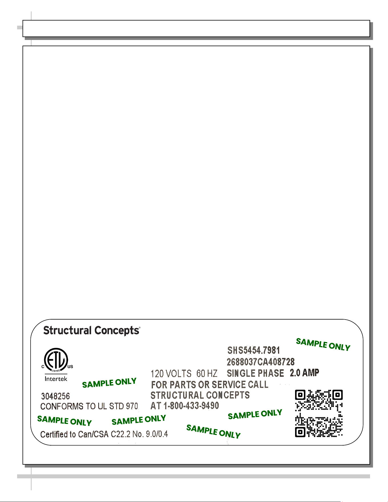
SERIAL LABEL LOCATION & INFO LISTED / TECH INFO & SERVICE - AMBIENT/HEATED CASES ONLY
Serial Label Location & Information Listed /
Technical Information & Service
• Serial labels are affixed at a wide range of places
(on the header, at case rear, behind panels or
toe-kicks, on electrical boxes, etc.).
• Serial labels contain electrical information as well
as regulatory standards to which the case
conforms.
• Sample serial label is shown. A variety of models is
displayed on serial label for illustration purposes only.
Your case’s serial label will reflect only one model.
• For additional technical information and service, see
the TECHNICAL SERVICE page in this manual for
instructions on contacting Structural Concepts’
Technical Service Department.
--- Sample Serial Label For Ambient/Heated Cases ---
888 E. Porter Rd - Muskegon, MI 49441
Sample QR Code
SCAN FOR PRODUCT LITERATURE
Reveal
Harmony
Impulse
Addenda
STRUCTURAL CONCEPTS TECHNICAL SERVICE CONTACT INFORMATION & LIMITED WARRANTY
19
TECH SERVICE/WARRANTY CONTACT INFO:
1 (800) 433-9490 / EXTENSION 1
DAYS/HOURS AVAILABLE:
MONDAY - FRIDAY (CLOSED HOLIDAYS)
8:00 AM to 8:00 PM EST
YOU MUST HAVE THE FOLLOWING INFO AVAILABLE
BEFORE CONTACTING STRUCTURAL CONCEPTS:
SERIAL NO. / MODEL NO. / STORE NO. / STORE
ADDRESS / DETAILS (PHOTOS, LEAK LOCATIONS,
DAMAGE, STORE’S AMBIENT CONDITIONS, ETC.)
To Access The Limited Warranty To Your
Case, Follow These Instructions:
> If Viewing This Document on Smart Phone,
Tablet or Computer, Select/Click On The QR
Code at Right.
> If Viewing This Document In Print (Hard
Copy), Scan The QR Code at Right With Your
Smart Phone or Tablet.