
I
User Manual
MDMAXPROHD
2311226-16
www.matcotools.com 877-853-3738
WARNING
Study, understand and follow all instructions provided with this product. Read these instructions carefully
before installing, operating, servicing or repairing this tool. Keep these instructions in a safe, accessible
place.
Caution: To help prevent personal injury,
1. Always perform automotive testing in a safe environment.
2. Do not connect or disconnect any test equipment while the ignition is on or the engine is running.
3. DO NOT attempt to operate the tool while driving the vehicle. Have second personal operate the tool.
Any distraction may cause an accident.
4. Before starting the engine, put the gear lever in the Neutral position (for manual transmission) or in
the Park (for automatic transmission) position to avoid injury.
5. NEVER smoke or allow a spark or flame in vicinity of battery or engine. Do not operate the tool in
explosive atmospheres, such as in the presence of flammable liquids, gases, or heavy dust.
6. Keep a fire extinguisher suitable for gasoline/chemical/electrical fires nearby.
7. Wear an ANSI-approved eye shield when testing or repairing vehicles.
8. Put blocks in front of the drive wheels and never leave the vehicle unattended while testing.
9. Use extreme caution when working around the ignition coil, distributor cap, ignition wires and spark
plugs. These components create hazardous voltage when the engine is running.
10. To avoid damaging the tool or generating false data, please make sure the vehicle battery is fully
charged and the connection to the vehicle DLC (Data Link Connector) is clear and secure.
11. Automotive batteries contain sulfuric acid that is harmful to skin. In operation, direct contact with the
automotive batteries should be avoided. Keep the ignition sources away from the battery at all times.
12. Keep the tool dry, clean, free from oil, water or grease. Use a mild detergent on a clean cloth to clear
the outside of the equipment when necessary.
13. Keep clothing, hair, hands, tools, test equipment, etc. away from all moving or hot engine parts.
14. Store the tool and accessories in a locked area out of the reach of children.
15. Do not use the tool while standing in water.
16. Do not expose the tool or power adapter to rain or wet conditions. Water entering the tool or power
adapter increases the risk of electric shock.
1 7. When an engine is operating, keep the service area well-ventilated or attach a building exhaust
removal system to the engine exhaust system. Engines produce various poisonous compounds
(hydrocarbon, carbon monoxide, nitrogen oxides, etc.) that cause slower reaction time and result in
death or serious personal injury.
INTENDED USE OF THE TOOL
Compatible with heavy-duty and commercial vehicles, the MDMAXPROHD diagnostic tool is exclusively
intended for professional technicians.
Do not use this tool outside of the designed intent. Never modify the tool for any other purpose or use.
PRODUCT INFORMATION
Made in China
to Matco specifications
II
User Manual
MDMAXPROHD
www.matcotools.com 877-853-3738
2311226-16
Using This Manual
This manual contains device usage instructions.
Some illustrations shown in this manual may contain modules and optional equipment that are not included
in your system.
Conventions
The following conventions are used.
Notes
A NOTE provides helpful information such as additional explanations, tips, and comments.
Example:
Note: In general, vehicle identification numbers are standardized - all contain 17 characters. VIN
characters may be capital letters A through Z and numbers 1 through 0; however, the letters I, O and Q
are never used in order to avoid mistakes of misreading. No signs or spaces are allowed in the VIN.
Warning
WARNING indicates a hazardous situation which, if not avoided, could result in minor or moderate injury to
the operator or to bystanders.
Example:
Warning: Retrieving and using DTCs for troubleshooting vehicle operation is only one part of an overall
diagnostic strategy. Never replace a part based only on the DTC definition. Each DTC has a set of testing
procedures, instructions and flow charts that must be followed to confirm the location of the problem. This
information can be found in the vehicle’s service manual.
Danger
DANGER indicates an imminently or potentially hazardous situation which, if not avoided, could result in
death or serious injury to the operator or to bystanders.
Example:
Danger: If you must drive the vehicle in order to perform a troubleshooting procedure, always have
a second person help you. Trying to drive and operate the diagnostic tool at the same time is dangerous,
and could cause a serious traffic accident.
Illustrations
Illustrations used in this manual are samples, the actual testing screen may vary for each vehicle being
tested. Observe the menu titles and on-screen instructions to make correct option selection.
Compliance Information
FCC ID: 2AUKMMAXFLEXPRO
Any changes or modifications not expressly approved by the party responsible for compliance could void
the user’s authority to operate the equipment.
This device complies with Part 15 of the FCC Rules. Operation is subject to the following two conditions:
(1) This device may not cause harmful interference, and
(2) This device must accept any interference received, including interference that may cause undesired
operation.
Note: This equipment has been tested and found to comply with the limits for a Class B digital device,
pursuant to part 15 of the FCC Rules. These limits are designed to provide reasonable protection against
harmful interference in a residential installation. This equipment generates, uses and can radiate radio

III
User Manual
MDMAXPROHD
2311226-16
www.matcotools.com 877-853-3738
frequency energy and, if not installed and used in accordance with the instructions, may cause harmful
interference to radio communications. However, there is no guarantee that interference will not occur in
a particular installation. If this equipment does cause harmful interference to radio or television reception,
which can be determined by turning the equipment off and on, the user is encouraged to try to correct the
interference by one or more of the following measures:
- Reorient or relocate the receiving antenna.
- Increase the separation between the equipment and receiver.
- Connect the equipment into an outlet on a circuit different from that to which the receiver is connected.
- Consult the dealer or an experienced radio/TV technician for help.
The device has been evaluated to meet general RF exposure requirement. The highest reported SAR for
stand-alone and simultaneous transmission exposure conditions are below the maximum value. End-users
must be informed of the operating requirements for satisfying RF exposure compliance.

IV
User Manual
MDMAXPROHD
www.matcotools.com 877-853-3738
2311226-16
Table of Contents目目
1 Introduction ................................................................................................................................................ 1
1.1 Product Profile ........................................................................................................................................... 1
1.2 Accessory Checklist .................................................................................................................................. 2
2 Components & Controls ............................................................................................................................ 4
2.1 Display Tablet ............................................................................................................................................ 4
2.2 VCI Device ................................................................................................................................................ 6
2.3 Technical Specifications ............................................................................................................................ 7
3 Initial Use .................................................................................................................................................... 8
3.1 Charging the Tablet ................................................................................................................................... 8
3.2 Power ON/OFF ......................................................................................................................................... 8
3.3 Locator & Navigation Buttons ................................................................................................................... 8
3.4 Wi-Fi Setup ............................................................................................................................................... 9
3.5 Adjust Brightness ..................................................................................................................................... 9
3.6 Change System Language ........................................................................................................................ 9
3.7 Set Standby Time ...................................................................................................................................... 9
4 Getting Started .......................................................................................................................................... 10
4.1 User Registration .....................................................................................................................................10
4.2 Basic Operations on Diagnostic App .......................................................................................................12
4.2.1 Switch between different function modules ..................................................................................12
4.2.2 How to arrange diagnostic vehicle software icons? .......................................................................12
4.2.3 How to distinguish if the software is locked or not? ......................................................................12
4.3 Function Modules ....................................................................................................................................13
4.3.1 Diagnostics .....................................................................................................................................13
4.3.2 Toolbox ...........................................................................................................................................13
4.4 Diagnostics toolbar ..................................................................................................................................14
5 Start Diagnostics ...................................................................................................................................... 15
5.1 Connections .............................................................................................................................................15
5.1.1 Preparation ......................................................................................................................................15
5.1.2 Vehicle Connection ..........................................................................................................................15
5.2 Communication Settings .........................................................................................................................15
5.3 Start Diagnostics .....................................................................................................................................16
5.3.1 System Scan ...................................................................................................................................16
5.3.2 Manual Diagnosis ...........................................................................................................................16
5.4 Diagnostic History (Previous Session) ................................................................................................... 22
5.5 HD Reset ................................................................................................................................................ 23
6 Toolbox ...................................................................................................................................................... 24
6.1 Maximus Fix HD .................................................................................................................................... 24
6.2 Saved Report .......................................................................................................................................... 24
6.3 Update .................................................................................................................................................... 24
6.3.1 Update Diagnostic Software & APP .............................................................................................. 24
6.3.2 Update Frequently Used software ................................................................................................. 25
6.4 Tech 2 Tech .............................................................................................................................................. 25
6.4.1 Add Friends .................................................................................................................................... 26
6.4.2 Start Instant Messaging ................................................................................................................ 26
6.4.3 Launch Remote Diagnosis (Scanner to Scanner)........................................................................... 27
6.4.4 Launch Remote Diagnosis (Scanner to PC) ................................................................................... 29

V
User Manual
MDMAXPROHD
2311226-16
www.matcotools.com 877-853-3738
6.5 Settings................................................................................................................................................... 30
6.5.1 General .......................................................................................................................................... 30
6.5.2 VCI ................................................................................................................................................. 31
6.5.3 VCI Management ........................................................................................................................... 31
6.5.4 ROXIE MANAGEMENT ................................................................................................................. 31
6.5.5 Color Theme .................................................................................................................................. 31
6.5.6 MD Printer Connection .................................................................................................................. 32
6.5.7 Shop Information ........................................................................................................................... 32
6.5.8 Shop Management ........................................................................................................................ 32
6.5.9 Favorites ........................................................................................................................................ 32
6.5.10 Hide or Remove Software............................................................................................................ 32
6.5.11 Backup/Restore ............................................................................................................................ 33
6.6 Feedback ................................................................................................................................................ 33
6.7 Videoscope ............................................................................................................................................. 33
6.8 MaxSensor ............................................................................................................................................. 33
6.9 About ...................................................................................................................................................... 33
7 FAQ ........................................................................................................................................................... 34

Safety & Accessory
Initial UseDiagnosticsFAQ & Appendix
Product Profile
1
2311226-16
www.matcotools.com 877-853-3738
User Manual
MDMAXPROHD
1 Introduction
1.1 Product Profile
MAXIMUS PROHD (MDMAXPROHD) is an evolutionary smart solution for specialized heavy-duty vehicle
diagnosis and maintenance. It inherits from advanced diagnosing technology and is characterized by
covering a wide range of vehicles, featuring powerful functions, and providing precise test result.
Through the wireless communication between VCI dongle and MDMAXPROHD tablet, it achieves full car
model and full system vehicle trouble diagnosis, which include Reading DTCs, Clearing DTCs, Reading Data
Stream, Actuation Test and Special Functions.
Moreover, taking advantage of the mobile Internet, it also integrates One-click Update, Tech 2 Tech (Remote
Diagnosis) and Repair Data, which helps to diagnose vehicle issues more efficiently, and greatly increase
customer’s retention and boost shop revenue.
MDMAXPROHD adopts a high performance-price ratio display tablet, which comes loaded with the
powerful 4-core 2.0GHz processor, 4G RAM, and a 10.1” IPS capacitive touch screen with a resolution of
1280 x 800 dots.
It supports the following functions:
• System Scan: This module allows you to quickly scan and access all available systems installed on the
test vehicle.
• Local Diagnosis: To perform diagnosis by executing on-screen commands step by step. Diagnosis
functions include: Read DTCs, Clear DTCs, Read Data Stream, Special Functions, etc.
• Tech 2 Tech (Remote Diagnosis): This option aims to help repair shops or technicians launch instant
messaging and remote diagnosis, making the repair job getting fixed faster.
• HD Service Reset: It offers coding, reset, relearn and more service functions, to help vehicles get back
to functional status after repair or replacement. Available tests vary by vehicle manufacturer, year, and
model.
• CAN BUS Pin Detection: Allows you to detect the voltage of the vehicle OBD II diagnostic socket pins
and the supported protocol types to help technicians judge the OBD II diagnostic interface.
• One-click Update: Lets you update your diagnostic software online.
• Diagnostic History (Previous Session): Provides a quick access to the tested vehicles and users can
choose to view the test report or resume from previous diagnostic session, without starting from scratch.
• Diagnostic Feedback: Enables you to submit the vehicle issue to us for analysis and troubleshooting.
• Vehicle Coverage: Quick dial to view the vehicle models that MDMAXPROHD covers.
• Backup/Restore: This feature lets you back up the recorded files to external storage device/restore the
recorded data from the external storage device.
• Add-on Modules: Video Scope and MaxSensor (sold separately) are available as add-on modules of the
MDMAXPROHD.
Safety & Accessory
Initial Use
Diagnostics
FAQ & Appendix
Product Profile
2
www.matcotools.com 877-853-3738
2311226-16
User Manual
MDMAXPROHD
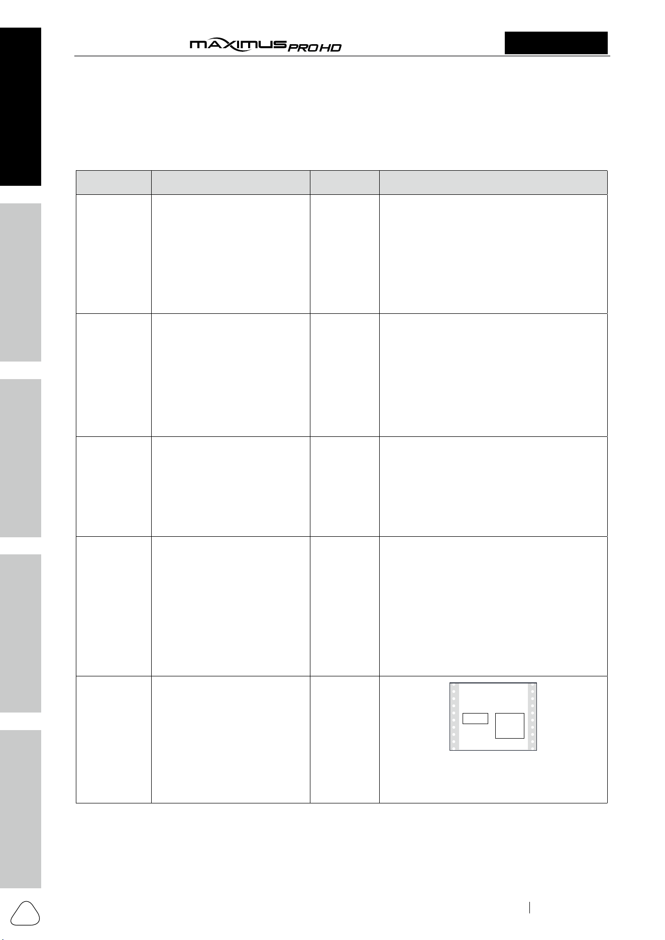
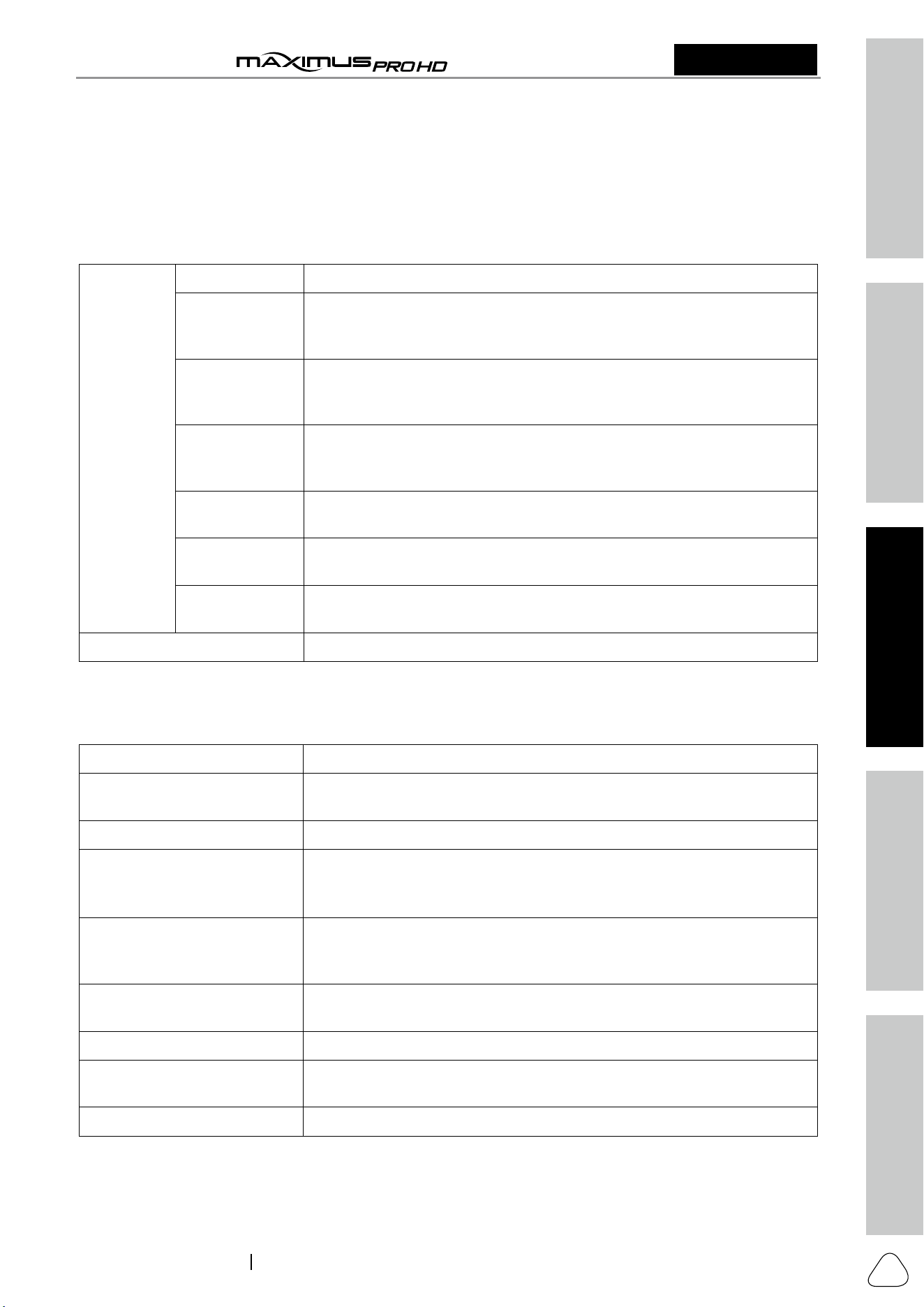
1.2 Accessory Checklist
Common accessories are same, but for different destinations, the accessories may vary. The following
accessory items are only for reference. Please consult from the Matco Distributor or check the package list
supplied with this tool together.
No. Name Qt. Picture & Notes
1 Display Tablet 1
(A tablet for showing test results.)
2
VCI (Vehicle Communication
Interface) device
1
(A device for accessing vehicle data.)
3 Power Adapter 1
(To supply power to the tablet through
connection to AC outlet.)
4 Diagnostic Cable
1
(Connects the VCI dongle to the vehicle’s
OBD II DLC port. It can be separated into
two parts: DB15F to HD15F data cable and
HD15M to OBD II adapter.)
5 Password Envelope 1
(A piece of paper bearing Product S/N and
Activation Code, which is required for your
registration.)

Safety & Accessory
Initial UseDiagnosticsFAQ & Appendix
Product Profile
3
2311226-16
www.matcotools.com 877-853-3738
User Manual
MDMAXPROHD
6 Data Cable 1
(Connect the VCI and diagnostic tool to
perform vehicle diagnosis.)
7 Battery Cable Clamps 1
(To provide power to the non-16pin
connector through connection to the
vehicle's battery.)
8 Cigarette Lighter Cable 1
(Supply power to the VCI through connection
to cigarette lighter receptacle.)
9 Adapter Cables 1
(Connect the diagnostic cable and vehicle’s
non-OBD II diagnostic socket.)
Safety & Accessory
Initial Use
Diagnostics
FAQ & Appendix
Product Profile
4
User Manual
MDMAXPROHD
www.matcotools.com 877-853-3738
2311226-16
2 Components & Controls
There are two main components to the diagnostic system:
• Display Tablet -- the central processor and monitor for the system (For details, please refer to Chapter
2.1.)
• VCI device -- the device for accessing vehicle data (For details, please refer to Chapter 2.2.)
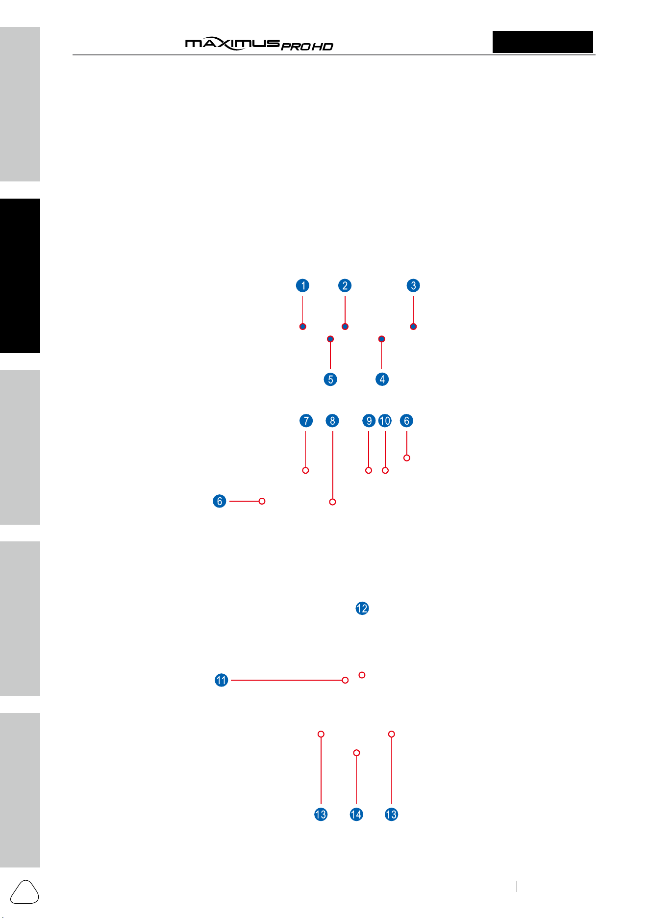
2.1 Display Tablet
The tablet acts as the central processing system, which is used to receive and analyze the live vehicle data
from the VCI device and then output the test result.
The following table formulates ports and indicators of display tablet:
Safety & Accessory
Initial UseDiagnosticsFAQ & Appendix
Product Profile
5
User Manual
MDMAXPROHD
2311226-16
www.matcotools.com 877-853-3738
No. Name & Descriptions
1 Memory Card Slot -- To store the memory card for storage expansion.
2 Type C Charging Port -- Reserved for charging the tablet.
3
Power/Screen Lock Button -- To turn the tablet on/off with long press, or lock the screen
with short press.
4 Volume Buttons -- To adjust the volume.
5
Data Transmission Port -- Reserved for add-on modules (such as Videoscope, etc.), and
other devices with similar port.
6 Microphone
7
Charging indicator -- It illuminates red while the tablet is charging. Once it is fully charged,
it will illuminate solid green.
8 10.1" Capacitive Touch Screen
9 Ambient Light Sensor
10 Front Camera
11 Rear Camera
12 Camera Flash
13 Audio Speaker
14
Adjustable Kickstand - Flip out it to any angle and work comfortable at your desk, or hang
it on the steering wheel.
Safety & Accessory
Initial Use
Diagnostics
FAQ & Appendix
Product Profile
6
User Manual
MDMAXPROHD
www.matcotools.com 877-853-3738
2311226-16
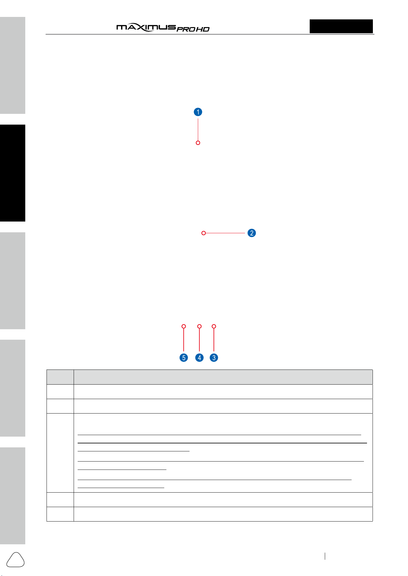
2.2 VCI Device
The MAXSYNC VCI dongle works as a heavy duty / medium duty / light duty vehicle communication
interface device, which is used to connect to the vehicle’s DLC (Data Link Connector) port via the diagnostic
cable to read the test data and then send it to the tablet.
No. Name & Descriptions
1 DB-15 Diagnostic Connector -- To connect the diagnostic cable.
2 Touch Screen
3
DC-IN Port
*Warning: The VCI dongle obtains power through the vehicle's DLC (Data Link Connector) via
the diagnostic cable. Do NOT connect the DC-IN port to an external DC power supply if the VCI
dongle can be powered up normally.
If the pin of the DLC is damaged or the DLC has insufficient power, connect the DC-IN port to
an external DC power supply.
No responsibility can be assumed for any damage or loss caused as a result of not strictly
following the above method.
4 Data I/O Port -- To connect it to the tablet to perform diagnosis via the data cable.
5 LAN/WAN Port -- Reserved for other purposes.
Safety & Accessory
Initial UseDiagnosticsFAQ & Appendix
Product Profile
7
User Manual
MDMAXPROHD
2311226-16
www.matcotools.com 877-853-3738
2.3 Technical Specifications
A. Display Tablet
Item Description
Operating system Android 10.0
CPU 4-core processor, 2.0GHz
Display 10.1 inch capacitive touch screen with 1280 x 800 resolution
Memory 4GB
Storage 128GB
Connectivity • WLAN (802.11 b/g/n/ac)
• USB ports (1 x Type-C + 1 x Type-A)
• BT2.1, BT3.0, BT4.0, BT4.1, BT5.0, BT5.1
Cameras 2MP front-facing camera + 8MP rear-facing camera
HDMI • Gravity Accelerometer
• 3-Axis Acceleration Sensor
Operating Temperature 32 ~122
℉
Storage Temperature -4 ~158
℉
B. VCI device
Item Description
Power Supply DC 9V ~ 36V
Operating System Linux
Memory 256MB
Storage 8GB
Connectivity
• Wi-Fi: Dual Band 2.4 & 5GHz
• DB15 port + Type-B USB port + RJ15 port + DC-IN port
Working Temperature 32 ~122
℉
Safety & Accessory
Initial Use
Diagnostics
FAQ & Appendix
Product Profile
8
User Manual
MDMAXPROHD
www.matcotools.com 877-853-3738
2311226-16
3 Initial Use
3.1 Charging the Tablet
Warning:
• Only use the included power adapter to recharge the tablet. Use of any other adapter will damage the
tool. We assume no responsibility for damage or loss resulting from using other similar adapters other
than the specified one.
• Always charge on a non-flammable surface in a well-ventilated area.
To check the battery power level, press and hold the Power button about 3 seconds to turn on the tablet.
Power level is indicated as a percentage in the upper right corner of the screen. If the power level drops
below 10% while the tablet is on, a Connect Charger notification will appear on the screen.
1. Connect one end of the power adapter to Type C
charging port of the tablet, and the other end to the
AC outlet.
2. The charging LED illuminates solid red and the
charging symbol
will appear on the screen.
3. Once it illuminates solid green, it indicates that
the battery is fully charged and the charging
complete symbol
replaces the charging sym-
bol. Disconnect the power adapter from the AC
outlet.
3.2 Power ON/OFF
Note: If it is the first time you use the tablet or the tablet keeps idle for a long time, it could fail to be
turned on. It results from low battery. In this case, please recharge it for a while and try to turn it on.
1. Press and hold the POWER button for about 3 sec-
onds to turn on the tablet. The system starts initial-
izing and then enters the Home screen.
2. To turn the tablet off, press and hold the
POWER button until an option menu appears.
Tap Power Off.
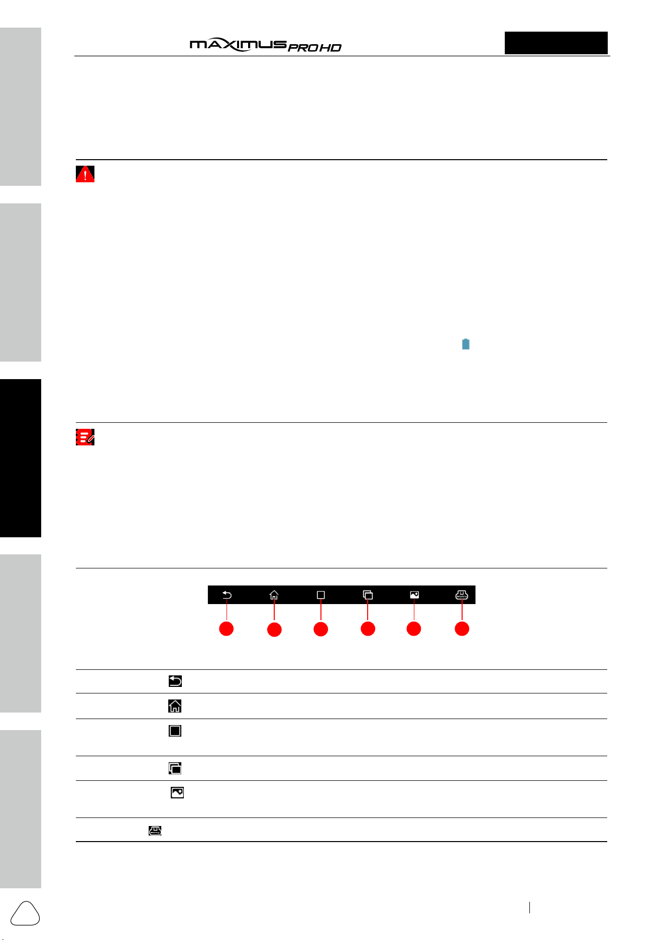
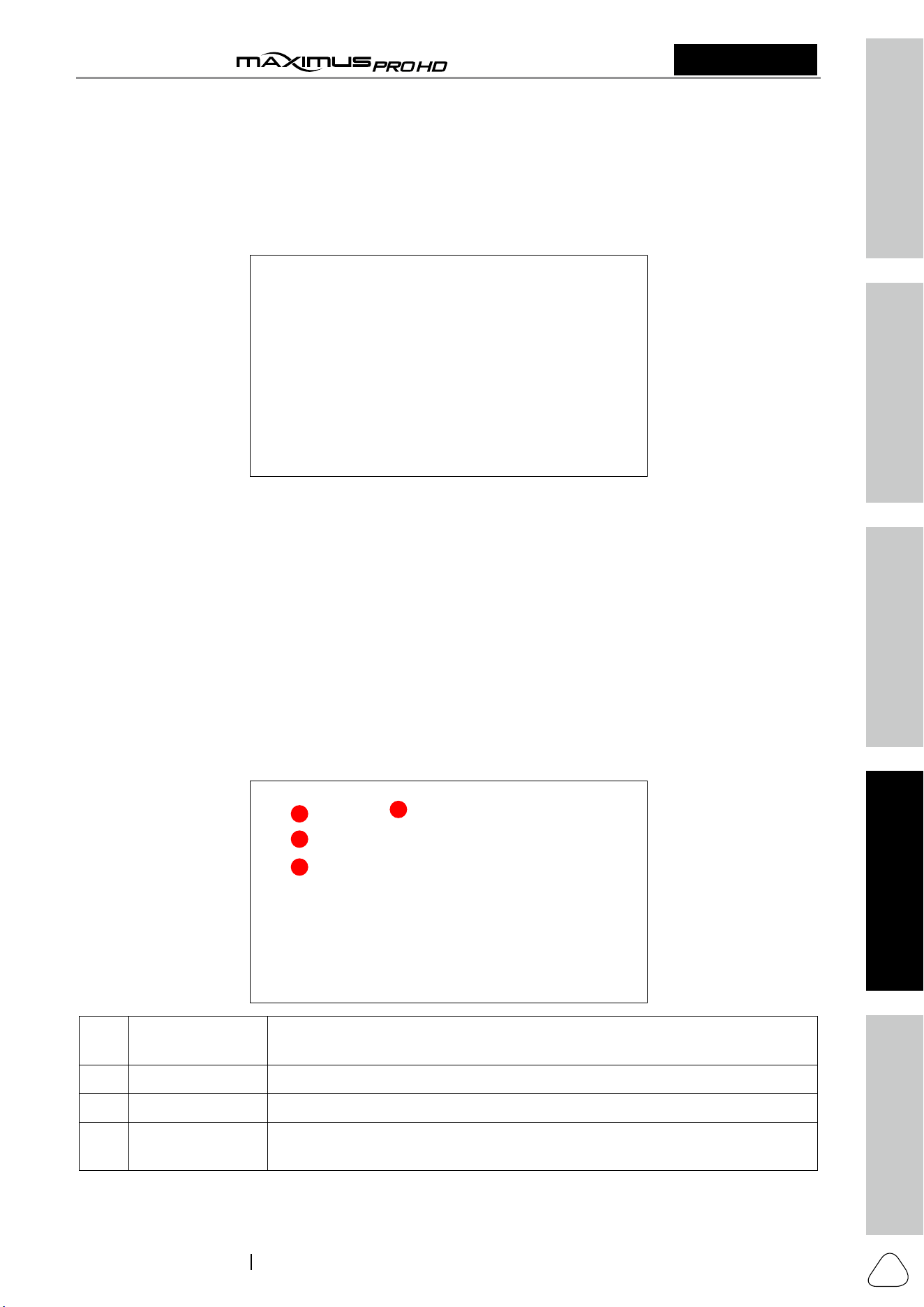
3.3 Locator & Navigation Buttons
1
2
3
4 5 6
On-screen keys and status bar are as follows:
1 Tap
to return to previous screen or exit the application.
2 Tap
to navigate to the Android System’s home screen.
3
Tap
to display a list of applications that are currently running or recently used. To open an
application, tap it. To remove an application, swipe it upwards.
4 Tap
to display all in-app tasks that are currently running.
5
Tap
to capture the current screen and all captured screenshots are stored in the
Screenshots folder.
6
: Shows whether the VCI device is properly connected or not.

Safety & Accessory
Initial UseDiagnosticsFAQ & Appendix
Product Profile
9
User Manual
MDMAXPROHD
2311226-16
www.matcotools.com 877-853-3738
3.4 Wi-Fi Setup
MDMAXPROHD has built-in Wi-Fi that can be used to get online. Once you’re online, you can register your
tool, update diagnostic software & APK, browse the Internet, get apps and send email on your network.
Note: Once WLAN is set as ON, the tablet will consume more power. While it keeps unused, please
set it off to save power. While WLAN is not in use, please turn it off to conserve battery power.
Connect to a WLAN Network
1. On the Home screen, tap Settings -> Network & in-
ternet -> Wi-Fi.
2. Slide the Wi-Fi switch to ON, the tablet starts search-
ing for available wireless LANs.
3. Select the desired WLAN network from the
list. If the chosen network is open, you can
connect directly. A password may be required
for secured networks.
Disconnect from a WLAN Network
1. On the Home screen, tap Settings -> Network & in-
ternet -> Wi-Fi.
2. Tap the network with a Connected status, then
tap Forget.
3.5 Adjust Brightness
Note: Reducing the brightness of the screen is helpful to conserve the battery power.
1. On the home screen, tap Settings -> Display ->
Brightness level.
2. Drag the slider to adjust it.
3.6 Change System Language
The tool supports multiple system languages. To change the language of the tool, please do the following:
1. On the home screen, tap Settings -> System -> Lan-
guage & input -> Languages.
2. Tap Add a language, and then choose the desired
language from the list.
3. Tap and hold the desired language and drag it
to the top of the screen and then release it, the
system will change into the target language.
3.7 Set Standby Time
If no activities are made within the defined standby period, the screen will be locked automatically and the
system enters sleep mode to save power.
1. On the home screen, tap Settings -> Display -> Ad-
vanced -> Screen timeout.
2. Choose the desired sleep time.

Safety & Accessory
Initial Use
Diagnostics
FAQ & Appendix
Product Profile
10
User Manual
MDMAXPROHD
www.matcotools.com 877-853-3738
2311226-16
4 Getting Started
4.1 User Registration
Users need to go through an sign-up process before using MDMAXPROHD.
Notes:
• Before registering, please make sure that your tablet has a strong and stable Wi-Fi signal.
• While activating device, the Serial number and Verification code can be found in the included password
envelope. To obtain Activation code, please contact with your dealer.
Follow the steps below to proceed:
1. Tap “MDMAXPROHD” on the home screen. For new user, tap “REGISTER” to go to step 2.
2. Fill in your account information and device information and then tap “ACTIVATE”.
Notes:
Serial number is a 12-digit number starting with 98 -- you can find it on the back of your tool.
Verification code is a 8-digit number stored in the Private & Confidential sheet.
Activation code is printed on the receipt, or consult your dealer for it.
On-screen Buttons:
Forgot Password: If you forgot the password, tap it and then follow the on-screen instructions to reset a
new password.
3. Tap “RUN DIAGNOSTICS” to launch diagnostics.

Safety & Accessory
Initial UseDiagnosticsFAQ & Appendix
Product Profile
11
User Manual
MDMAXPROHD
2311226-16
www.matcotools.com 877-853-3738
“MANAGE SUBSCRIPTIONS” enables you to renew your subscriptions or purchase new software
packages.
On-screen Buttons:
Sign Out: Tap it to log out the system.
Update Profile: Tap it to modify personal information.
4. Tap “
” on the top left-hand corner of the screen to switch to the Toolbox module.
Note: If a number indicator appears on upper right corner of the Update logo, it indicates newer
software is available.
5. Tap “Update” to enter the update center.

Safety & Accessory
Initial Use
Diagnostics
FAQ & Appendix
Product Profile
12
User Manual
MDMAXPROHD
www.matcotools.com 877-853-3738
2311226-16
Make sure all brands are selected, tap “Update” to start updating.
Tap the “OK” button on the pop-up message box when update is complete.
Note: Download and installation will take approximately 10 minutes depending on the internet
connection.
4.2 Basic Operations on Diagnostic App
4.2.1 Switch between different function modules
There are 2 function modules available on the MDMAXPROHD: Diagnostics and Toolbox.
Swipe in from the left/right edge of the screen to switch between function modules.
Alternatively, you can also tap
on the upper left corner of the screen to toggle between Diagnostics
and Toolbox.
4.2.2 How to arrange diagnostic vehicle software icons?
All software icons, by default are organized by the system. Many display rules are available to meet your
preference.
To re-organize it, press and hold certain software icon, an option menu will pop up on the screen. Choose
the display rule and the system will arrange the icon as desired.
If you choose “Pin to the top”, the icon will be displayed on the top of the screen and marked with an
orange solid dot.
4.2.3 How to distinguish if the software is locked or not?
If the software is locked, tap it to display the latest software summary. In this case, you need to purchase
the software to unlock its content. Once it is unlocked, the software icon will turn into orange.
Safety & Accessory
Initial UseDiagnosticsFAQ & Appendix
Product Profile
13
User Manual
MDMAXPROHD
2311226-16
www.matcotools.com 877-853-3738
4.3 Function Modules
There are 2 function modules available on the MDMAXPROHD: Diagnostics and Toolbox.
4.3.1 Diagnostics
It mainly includes the following items:
Heavy Duty
System Scan Quickly scan which systems are equipped on the test vehicle.
CAN BUS Pin
Detection
Allows you to detect the voltage of the vehicle OBD II diagnostic socket
pins and the supported protocol types to help technicians judge the OBD
II diagnostic interface.
Maximus HD Fix
This modules allows you to access full instructions, flow charts, wiring
diagrams and more of heavy-duty vehicles to walk through how to fix and
finish the job.
HD Reset
It offers coding, reset, relearn and more service functions of heavy-duty
vehicles, to help vehicles get back to functional status after repair or
replacement.
Vehicle Voltage
Performs a check of the vehicle’s battery to ensure the system is
operating within acceptable limits.
Previous
Sessions
Provides a quick access to the previously tested vehicles. Testing can be
resumed from the previous operation without starting from scratch.
Explore OEM
Brands
Retrieve or select the desired vehicle diagnostic software.
Portal Quickly access our portal website.
4.3.2 Toolbox
It mainly includes the following items:
Maximus HD Fix Another access to the Maximus HD Fix on the main screen.
Saved Report
Includes Health report, Recorded Data, Remote Report, Data Samples
and ROXIE Reports.
Update To update vehicle diagnostic software and APK.
Tech 2 Tech
This option aims to help repair shops or technicians launch instant
messaging and remote diagnosis, making the repair job getting fixed
faster.
Settings
To make some system settings, including VCI Management, MD Printer
Connection, Shop Information, Icon Size, Vehicle Voltage and Hide/
Remove Software, etc.
Feedback
This item allows you to feedback your diagnostic problems to us for
analysis and troubleshooting.
Videoscope To check unseen or unreachable parts or components.
MaxSensor
This module is specially designed to diagnose and simulator vehicle
sensor faults quickly and conveniently.
About Includes FAQ, Vehicle Coverage, Quick Start Guide and User Manual, etc.

Safety & Accessory
Initial Use
Diagnostics
FAQ & Appendix
Product Profile
14
User Manual
MDMAXPROHD
www.matcotools.com 877-853-3738
2311226-16
4.4 Diagnostics toolbar
The diagnostics toolbar contains a number of buttons that enables various procedures. It is hidden under
at the top of the vehicle diagnostic screens throughout the diagnostic session. Refer to the table below
for a brief description of the functions of the diagnostics toolbar buttons.
Print
Tap to print the current screen.
To perform printing, you need to purchase an extra Wi-Fi printer
separately.
Exit Session Tap to exit the current diagnostic session.
Safety & Accessory
Initial UseDiagnosticsFAQ & Appendix
Product Profile
15
User Manual
MDMAXPROHD
2311226-16
www.matcotools.com 877-853-3738
5 Start Diagnostics
5.1 Connections
5.1.1 Preparation
1. Make sure that the ignition is turned off and vehicle battery voltage range is 9-14V or 18-30V.
2. Find DLC location.
For Commercial Vehicles, the DLC is generally located in driver’s cab.
3. Refer to Chapter 5.1.2 to make connection.
4. Turn the vehicle’ ignition ON with engine OFF.
5. Now the tool is ready for diagnostics.
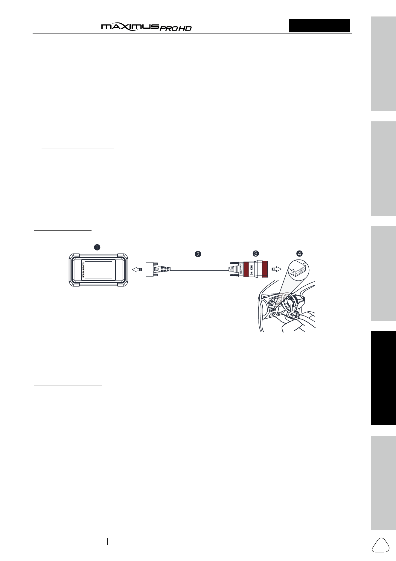
5.1.2 Vehicle Connection
The method used to connect the VCI device to a vehicle’s DLC depends on the vehicle’s configuration as
follows:
For OBD II vehicles, use the included diagnostic cable (DB15F to HD15F data cable and HD15M to OBD16
adapter) to connect the VCI to the vehicle’s DLC port.
1. VCI
2. DB15F to HD15F data cable
3. HD15M to OBD16 adapter
4. Vehicle’s DLC port
For non-OBDII vehicles, refer to the above figure to make connection.
1. Select the appropriate adapter according to the vehicle’s DLC port type (4).
2. Loosen the captive screws of the DB15F to HD15F data cable (2) and disconnect the HD15M to OBD16
adapter (3) from the data cable.
3. Connect the data cable (2) with the target adapter on the above figure and tighten the screws. Other
steps shall also apply.
If you choose to perform vehicle diagnosis via data cable, connect one end of the data cable into the VCI,
and the other end into the data transmission port of the tablet.
5.2 Communication Settings
There are two kinds of ways available for the tablet to communicate with the VCI device: wireless and
wired (USB).
After the user registration is successfully finished, the wireless communication between the tablet and the
VCI device is automatically established and user has no need to configure it again.
The USB connection is a simple & quick way to establish communication between the tablet and the VCI.
After properly connecting the data cable from the tablet to the VCI, the VCI navigation button at the bottom

Safety & Accessory
Initial Use
Diagnostics
FAQ & Appendix
Product Profile
16
User Manual
MDMAXPROHD
www.matcotools.com 877-853-3738
2311226-16
of the screen will be enabled indicating the USB connection is successful.
Note: The USB connection provides the most stable and fastest communication. When all
communication methods are applied at the same time, the tablet will use the USB communication as the
default priority.
5.3 Start Diagnostics
On the Diagnostics page, tap “Heavy Duty” to enter the vehicle selection page.
2 approaches are provided for you to access the vehicle diagnostic software.
5.3.1 System Scan
Through simple wireless communication between the tablet and VCI, you can quickly scan all available
systems of the currently identified vehicle. Once the automatic detection is successfully performed, the
system will directly output the scan result.
*Notes:
• Before using this function, please make sure the VCI is properly connected to the vehicle’s DLC. For
detailed connection, see Chapter 5.1.2 “Vehicle Connection”.
• A stable network connection is required for this function.
Tap the desired system to enter the diagnostic function selection screen. For details, refer to Chapter 5.3.2.
5.3.2 Manual Diagnosis
Take Demo V15.03 as an example to demonstrate how to diagnose a vehicle.
1). Explore OEM vehicle brand: Tap “Explore OEM Brands” to go to Step 2.
2). Select diagnostic software version: Tap “DEMO”.
On-screen Buttons:
Vehicle Coverage: Tap to view the vehicle models that the current diagnostic software covers.
What’s new: Tap to view the optimized items and enhancements.
Introduction: Tap to check the software function list.
Note: Tap to read some precautions on using the current diagnostic software.
Search Bluetooth: Tap to search for all available Bluetooth devices.
OK: Tap it to go to next step.
3). Select test vehicle (varies with different versions): Select the desired vehicle (Take “FreightLiner” for
example) to continue.
Safety & Accessory
Initial UseDiagnosticsFAQ & Appendix
Product Profile
17
User Manual
MDMAXPROHD
2311226-16
www.matcotools.com 877-853-3738
4). Select test system: Select the target test system.
5). Select test item: Select the desired test item to proceed.
Note: Diagnostic report is classified into two categories: Pre-Repair report and Post-Repair report.
To facilitate the comparison of the pre-repair and post-repair reports and get accurate test result, please
make sure you saved the right type of the diagnostic report.
• In Technician Name field, input the technician name (*If you have entered the technician name before,
tap
directly to select it from the pull-down list).
• Tap “Customer Concerns”, select the fault symptom information from the list and tap “OK” to confirm.
• In Notes text box, write down more description about the diagnostic trouble codes.
• To make the fault symptom more intuitive, you may also tap “Add Picture” to take a photo or upload a
local photo.
After filling it, tap “OK” to save it as a diagnostic report and navigate to the report details page.
Note: Different vehicle has different diagnostic menus.
A. Read Fault Code

Safety & Accessory
Initial Use
Diagnostics
FAQ & Appendix
Product Profile
18
User Manual
MDMAXPROHD
www.matcotools.com 877-853-3738
2311226-16
This function displays the detailed information of DTC records retrieved from the vehicle’s control system.
Note: Retrieving and using DTCs for troubleshooting vehicle operation is only one part of an overall
diagnostic strategy. Never replace a part based only on the DTC definition. Each DTC has a set of testing
procedures, instructions and flow charts that must be followed to confirm the location of the problem.
This information can be found in the vehicle’s service manual.
On the diagnostic function selection screen, tap “Read Fault Code”, the screen will display the diagnostic
result.
On-screen Buttons:
Maximus Fix HD: Tap to retrieve it and find possible cause & verified solution from the Maximus Fix HD.
Google Search: Highlight the desired DTC, and tap it to search in the Google engine for more detailed
information about the selected DTC.
Report: To save the current data in text format. All diagnostic reports can be accessed from “Toolbox” ->
“Saved Reports” -> “Health Report”.
Note: Diagnostic report is classified into three categories: Pre-Repair report, Post-Repair report and
Diagnostic Scan.
To facilitate the comparison of the pre-repair and post-repair reports and get accurate test result, please
make sure you saved the right type of the diagnostic report.
Safety & Accessory
Initial UseDiagnosticsFAQ & Appendix
Product Profile
19
User Manual
MDMAXPROHD
2311226-16
www.matcotools.com 877-853-3738
On-screen Buttons:
Customer Signature: Tap to create customer signature.
Print: Tap to print the report out via the external printer.
Share: Tap to share the report with others.
By default, the workshop information is blank. You can configure and revise it from the “Shop Information”
in “Toolbox” -> “Settings”.
Once you configured the information, it will be automatically generated every time the diagnostic report
is saved. All vehicle and workshop information will be appended as a tag on the diagnostic report, which
allows you to easily retrieve the desired report while performing “Filter” function of Diagnostic Report.
B. Clear Fault Code
After reading the retrieved codes from the vehicle and certain repairs have been carried out, you can use
this function to erase the codes from the vehicle. Before performing this function, please be sure the
vehicle’s ignition key is in the ON position with the engine off.
Clearing DTCs does not fix the problem(s) that caused the code(s) to be set. If proper repairs to correct the
problem that caused the code(s) to be set are not made, the code(s) will appear again and the check engine
light will illuminate as soon as the problem that cause the DTC to set manifests itself.
On the diagnostic function selection screen, tap “Clear Fault Code”, a confirmation dialog box pops up on
the screen. Tap “Yes” and the system will automatically delete the currently existing trouble code.
Warning: After clearing, you should retrieve trouble codes once more or turn ignition on and retrieve
codes again. If there are still some trouble codes in the system, please troubleshoot the code using a
factory diagnosis guide, then clear the code and recheck.
C. Read Data Stream
This option lets you view and capture (record) real-time Live Data. This data including current operating
status for parameters and/or sensor information can provide insight on overall vehicle performance. It can
also be used to guide vehicle repair.
Danger: If you must drive the vehicle in order to perform a troubleshooting procedure, A LWAYS have
a second person help you. Trying to drive and operate the diagnostic tool at the same time is dangerous,
and could cause a serious traffic accident.
On the diagnostic function selection screen, tap “Read Data Stream”, the system will display data stream
items.

Safety & Accessory
Initial Use
Diagnostics
FAQ & Appendix
Product Profile
20
User Manual
MDMAXPROHD
www.matcotools.com 877-853-3738
2311226-16
On-screen Buttons:
Select Page: Tap it to select all items of the current page. To select certain data stream item, just check the
box before the item name.
Select All: Tap it to select all items of the current page. To select certain data stream item, just check the
box before the item name.
Unselect: Tap it to deselect all data stream items.
OK: Tap it to confirm and jump to the next step.
After selecting the desired items, tap “OK” to enter the data stream reading page.
Notes:
1. Tap English or Metric to switch the measurement unit.
2. If the value of the data stream item is out of the range of the standard (reference) value, the whole line
will display in red. If it complies with the reference value, it displays in blue (normal mode).
3. The indicator 1/X shown on the bottom of the screen stands for the current page/total page number.
Swipe the screen from the right/left to advance/return to the next/previous page.
There are 3 types of display modes available for data viewing, allowing you to view various types of
parameters in the most suitable way.
• Value – this is the default mode which displays the parameters in texts and shows in list format.
• Graph – displays the parameters in waveform graphs.
• Combine – this option is mostly used in graph merge status for data comparison. In this case, different
items are marked in different colors.
On-screen Buttons:
: Tap it to view the waveform graph of the current data stream item.
Safety & Accessory
Initial UseDiagnosticsFAQ & Appendix
Product Profile
21
User Manual
MDMAXPROHD
2311226-16
www.matcotools.com 877-853-3738
• Min/Max: Tap “Min/Max” to define the maximum/minimum value. Once the value goes beyond the
specified value, the system will alarm.
• Customize: If desired, you can customize to show only those PIDs you are interested in viewing. Tap
“Customize” to add/change other data stream items.
Note: The real time (Live Data) vehicle operating information (values/status) that the on-board
computer supplies to the tool for each sensor, actuator, switch, etc. is called Parameter Identification
Data (IPD).
Compare Sample: Tap it to select the sample file, the values you customized and saved in process of DS
sampling will be imported into the “Standard Range”column for your comparison.
Note: Before executing this function, you have to sample the values of data stream items and save it
as an sample data stream file.
Save Sample: This item enables you to customize the standard range of live data stream items and save
it as DS sample file. Each time you run the data stream items, you can call out the corresponding sample
data to overwrite the current standard range.
Tap it to start recording the sample data (*Only data stream items with units will be recorded). Once
recording is complete, tap
to stop it and navigate to the data revision screen.
Tap the Min./Max. value to change it. After modifying all desired items, tap “Save” to save it as an sample
DS file. All DS files are stored under the “Data Samples” file of “Saved Reports” in “Toolbox”.
Graph: Tap it to view the waveform.
• Combine: This option is mostly used in graph merge status for data comparison.
• Value: Tap to display the parameters in texts.
• Customize: This option allows you to select only the PIDs that you wish to display. Tap it, a pull-
down list of the data stream items appears on the screen. Select (Up to 8 data stream items can
be selected)/deselect the desired items and then screen will display/remove the corresponding
waveforms immediately.
Report: To save the current data as a diagnostic report. All diagnostic reports can be accessed from “Toolbox”

Safety & Accessory
Initial Use
Diagnostics
FAQ & Appendix
Product Profile
22
User Manual
MDMAXPROHD
www.matcotools.com 877-853-3738
2311226-16
-> “Saved Reports” -> “Health Report”.
Record: Tap to start recording diagnostic data. Recorded live data can serve as valuable information to help
you in troubleshooting of vehicle problems. All diagnostic records can be replayed from “Toolbox” -> “Saved
reports” -> “Recorded Data”.
Note: The saved file follows the naming rule: It begins with vehicle type, and then the record starting
time (To differentiate between files, please configure the accurate system time).
D. Actuation Test
This option is used to access vehicle-specific subsystem and component tests. Available test vary by
vehicle manufacturer, year, and model. During the actuation test, the MDMAXPROHD tablet outputs
commands to the ECU in order to drive the actuators, and then determines the integrity of the system or
parts by reading the ECU data, or by monitoring the operation of the actuators, such as switching a injector
between two operating states.
Simply follow the on-screen instructions and make appropriate selections to complete the test. Each time
when an operation is successfully executed, “Completed” displays.
E. Version Information
This function is used to read the version information of system mode, vehicle VIN, software and ECU.
F. Special Function
It offers coding, reset, relearn and more service functions, to help vehicles get back to functional status
after repair or replacement. It also can be accessed from “HD Reset” on the main menu screen directly.
5.4 Diagnostic History (Previous Session)
Generally once a vehicle diagnosis is performed, MDMAXPROHD will record the every details of diagnostic
process. The History function provides a quick access to the tested vehicles and users can resume from
the last operation, without starting from scratch.
Tap “Previous Session” on the main menu screen, all diagnostic records will be listed on the screen in date

Safety & Accessory
Initial UseDiagnosticsFAQ & Appendix
Product Profile
23
User Manual
MDMAXPROHD
2311226-16
www.matcotools.com 877-853-3738
sequence.
• Tap certain vehicle model to view the details of the last diagnostic report.
• To delete certain diagnostic history, select it and then tap “Delete”. To delete all historical records, tap
“Select All” and then tap “Delete”.
• Tap “Restore” to directly navigate to the function selection page of last diagnostic operation. Choose the
desired option to proceed.
5.5 HD Reset
It offers coding, reset, relearn and more service functions, to help vehicles get back to functional status
after repair or replacement. Available tests vary by vehicle manufacturer, year, and model.
Due to continuing improvements, the available service functions are subject to change at any time. To enjoy
more service functions, you are suggested to check for updates on a regular basis.

Safety & Accessory
Initial Use
Diagnostics
FAQ & Appendix
Product Profile
24
User Manual
MDMAXPROHD
www.matcotools.com 877-853-3738
2311226-16
6 Toolbox
6.1 Maximus Fix HD
This modules allows you to access full instructions, flow charts, wiring diagrams and more to walk through
how to fix and finish the vehicle repair job.
6.2 Saved Report
Tap “Saved Report”, it mainly includes the following options:
1. Health Reports
This module stores all diagnostic reports generated in process of vehicle diagnosis.
2. Remote Reports
This option lists all diagnostic reports generated in process of remote diagnostics.
3. Recorded Data
If user records the running parameters or waveform graphs while reading data stream, it will be saved as
diagnostic records and appear under this tab. You can use this option to view recorded live data. Frame
playback and auto playback are supported.
Note: While viewing recorded live data, carefully look for any irregularities in any of the PID values/
signal information (TEMP, RPM, etc). If any PIDs go beyond the standard range value, or irregularities are
detected, follow the procedures in the vehicle’s service manual to perform additional troubleshooting
and repair.
4. Data Samples
This feature allows you to manage the recorded data stream sample files.
5. Shared Data Samples
This feature lets you view the data stream sample files shared with others.
6. ROXIE Reports
This feature lets you manage all ROXIE reports generated by the bound ROXIE devices.
6.3 Update
This module allows you to update the diagnostic software & App and set frequently used software.
If you did not download the software in process of product activation or a number (indicating the available
software quantity) displaying on the upper right corner of the
icon, you may use this option to
download it or keep it synchronized with the latest version.
Tap “Update” to enter the update center.
6.3.1 Update Diagnostic Software & APP
The Available tab displays a list of software that can be updated. Under it, all software is categorized into
three kinds:
• Common software: mainly includes some common apps that are associated with the diagnostic app. The
software of this kind always stays at the top of the list, which can be deselected manually (excluding the
system app, such as firmware and ECU aid).
• Frequently used vehicle software: refers to the diagnostic software that is frequently used, including the
vehicle diagnostic software and Reset software. It is generally displayed following the Common software
list.
• Other vehicle software: refers to the diagnostic software that is rarely used or never used. It is generally
displayed following the Frequently used software list.
Safety & Accessory
Initial UseDiagnosticsFAQ & Appendix
Product Profile
25
User Manual
MDMAXPROHD
2311226-16
www.matcotools.com 877-853-3738
1). If the user does not download any diagnostic software during the sign-up process, all diagnostic
software is selected by default. Tap “Install” to start downloading.
2). If the user downloaded all/some vehicle software during the sign-up process and had it serviced for a
long period of time, only the frequently used software is selected. Tap “Install” to start downloading.
Other vehicle software that is rarely used will also be listed under the Available tab, but it is not selected
at default.
To download certain software that is not frequently used, check the box before the vehicle model. Tap
“Install” to start downloading.
Once download is finished, the software packages will be installed automatically.
6.3.2 Update Frequently Used software
If the user only intends to update the frequently used software, tap the Downloaded tab.
Tap “Install” to start downloading. Once download is finished, the software packages will be installed
automatically.
6.4 Tech 2 Tech
This option aims to help repair shops or technicians launch instant messaging and remote diagnosis,
making the vehicle (even thousands of miles away) repair job getting fixed faster.
1
2
3
4
1 Message tab
Once an incoming message reaches, a red dot will appear on the upper right
corner of the tab.
2 Contacts List Tap to enter the friend list.
3 Remote tab Set it to ON when asking for remote control.
4 Search bar
Directly input the partner’s S/N of the MDMAXPROHD to start searching, and
tap the desired one to add it into your friend list.
Safety & Accessory
Initial Use
Diagnostics
FAQ & Appendix
Product Profile
26
User Manual
MDMAXPROHD
www.matcotools.com 877-853-3738
2311226-16
6.4.1 Add Friends
Tap “Contacts” to enter the contact page. By default it appears blank.
In the search bar, input the partner’s username and tap “Search” button next to the search bar to starts
searching from Matco’s technician database.
Note: The partner must be the users who have registered their Matco’s diagnostic tools. They may
be the following:
• Workshop
• Technician
Once the result matches the keyword, the following screen will appear:
• To launch the remote diagnostics directly, tap “Remote Diagnose” to invite a remote control or request
control remote device.
• To view the partner’s detailed information, tap
to add him/her as your friend.
Once the partner agreed
your request, you will receive a piece of verification information and he/she will automatically be listed in
the Contact tab.
6.4.2 Start Instant Messaging
Note: The I/M (Instant Messaging) function is open to all users who had Matco’s diagnostic tool
equipped with this module.
There are two methods available for users to make a conversation on this module.
A. If you do not add the partner as your friend, tap “Send Message” to enter the following screen:
B. If you have added the partner into the Contacts, directly tap the desired fellow technician’s photo (avatar)
to start a conversation.
Tap the input field and use the on-screen keyboard to enter the text, and tap “Send”.
Safety & Accessory
Initial UseDiagnosticsFAQ & Appendix
Product Profile
27
User Manual
MDMAXPROHD
2311226-16
www.matcotools.com 877-853-3738
Here you can send voice and text messages. Tap + to call out more function options.
• Add friend: It is disabled if you have added the partner as your friend.
• File: Choose diagnostic reports or local files to send.
• Picture: Choose screenshots or pictures to send.
• Tech 2 Tech: To start a remote diagnostic session. For details, refer to Chapter 6.2.4.
• Camera: Open camera to take pictures.
Tap “Clear” to delete all the partner’s dialog logs.
6.4.3 Launch Remote Diagnosis (Scanner to Scanner)
The tablet is allowed to initiate remote diagnosis with other diagnostic tools (including but not limited to the
MDMAXPROHD) of Matco family, which are equipped with this module.
Note: Before performing this operation, please make sure the following conditions are met no matter
which side sends the remote request:
• Turn on the vehicle power supply.
• Throttle should be in a closed position.
• The VCI dongle should be properly connected to the vehicle’s DLC and a successful communication
with the tablet is required.
A. In case you do not add the partner as your friend, directly tap “Remote Diagnose”.
B. If you have added the partner into the Contact, tap + and select “Tech 2 Tech” from the pull-down option
list.
Safety & Accessory
Initial Use
Diagnostics
FAQ & Appendix
Product Profile
28
User Manual
MDMAXPROHD
www.matcotools.com 877-853-3738
2311226-16
The Tech 2 Tech options are defined as follows:
Actions Results
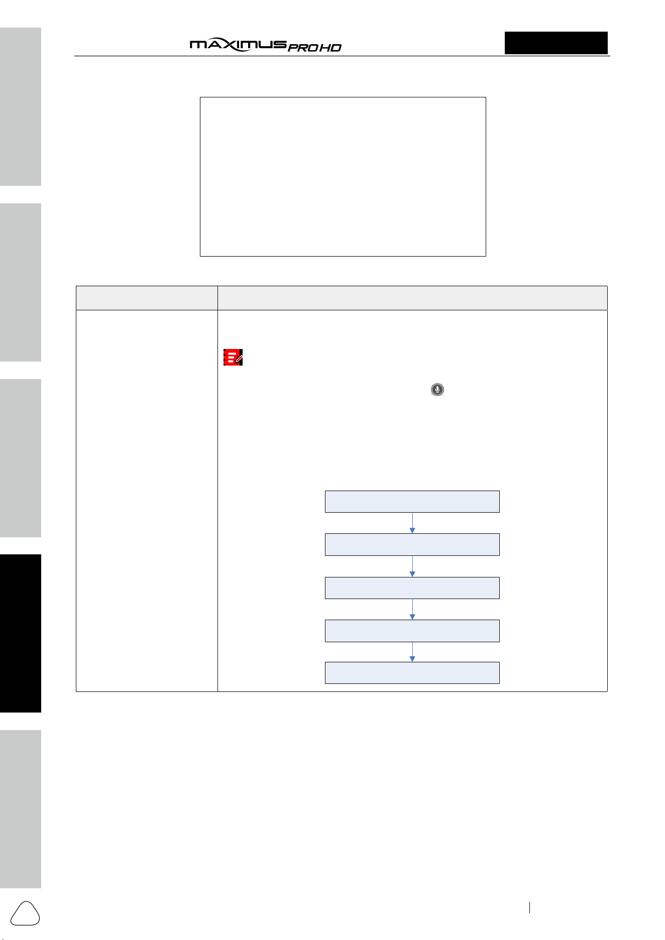
Request control remote
device
Request to control the partner’s device remotely to help him diagnose the
vehicle.
Notes:
• Remote diagnosis has the same diagnostic steps as manual diagnosis.
• In process of remote diagnosis, tap the
button to send a voice
message.
• Once vehicle diagnosis is complete, a report will be created. Input your
comments on this report, and then tap “Send Report” to send it to the
partner.
• If you have a local vehicle diagnosis in process, please exit it first before
starting remote diagnosis.
Tap “Request control remote device”
Wait for partner’s confirmation
Start connecting after request confirmed
Start Diagnosis
Generate diagnostic report
Safety & Accessory
Initial UseDiagnosticsFAQ & Appendix
Product Profile
29
User Manual
MDMAXPROHD
2311226-16
www.matcotools.com 877-853-3738
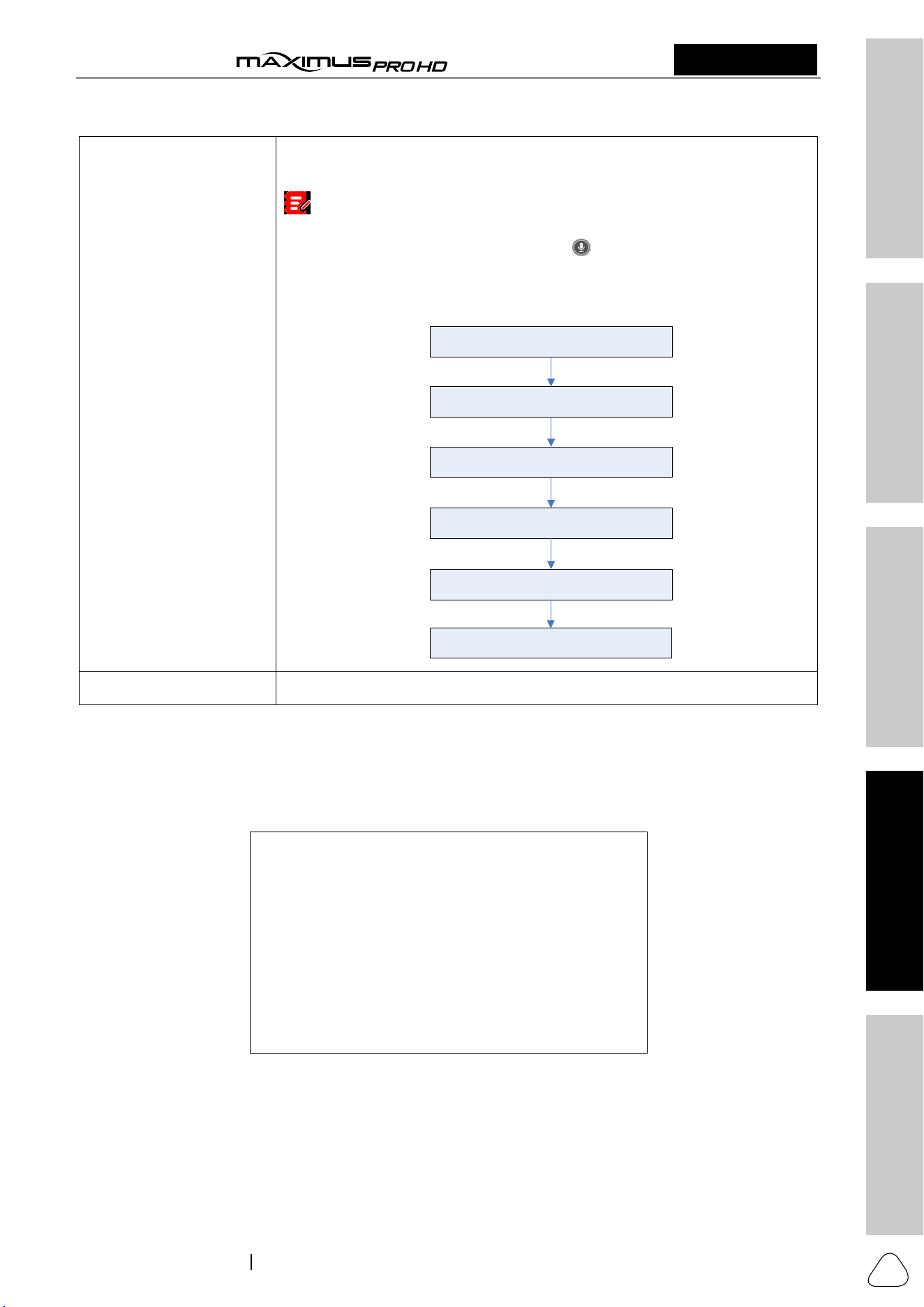
Invite remote diagnostic
assistant
If you need support, just use this option to invite a technician to perform a
remote control on your tool.
Notes:
• Remote diagnosis has the same diagnostic steps as manual diagnosis.
• In process of remote diagnosis, tap the
button to send voice message.
• Once you received the report from the partner, tap “View Report” to view
details. All diagnostic reports are saved “Toolbox” -> “Saved Reports” ->
“Remote Reports”.
Tap “Invite remote diagnostic assistant”
Choose the desired diagnostic software
Wait for partner’s confirmation
Start connecting after request confirmed
Start Diagnosis
Generate diagnostic report
Cancel To cancel this operation.
6.4.4 Launch Remote Diagnosis (Scanner to PC)
User also can ask for remote control from a PC client technician.
1. Tap “Remote”. Slide the switch to ON so that the partner can connect to your scanner, then select the
target vehicle model. The following screen will appear:
2. Notify the partner to visit the Matco web remote diagnostics platform (https://remotediag.x431.com/#/
login/?isMatco=1&lang=en) until the following screen appears on the PC.

Safety & Accessory
Initial Use
Diagnostics
FAQ & Appendix
Product Profile
30
User Manual
MDMAXPROHD
www.matcotools.com 877-853-3738
2311226-16
3. After the partner successfully logs in (using his own official technician account and password), the
following screen will appear.
4. Tell the partner to enter the Serial Number of your scanner, and then tap Start remote diagnosis to
control your scanner remotely.
If you need to provide remote diagnosis service for other diagnostic scanners, tap “Provide remote
assistant on web”, the following screen will appear:
1. Tap “Click to obtain” to get a temporary remote diagnostics platform account.
2. Open the Matco web remote diagnostics platform (https://remotediag.x431.com/#/
login/?isMatco=1&lang=en).
3. Enter the obtained username and password to log in and then enter the Serial Number of the scanner
that needs the help of remote diagnosis to start the diagnosis.
Notes: In process of remote diagnosis, please note the following things:
1) You are not suggested to execute any actions.
2) The partner is not allowed to save any diagnostic reports or records on your tablet.
Once the session is complete, a remote diagnostic report will be automatically generated.
6.5 Settings
This module allows you to manage diagnostic reports, VCI devices, configure wireless printer and print
information and add favorite website, etc.
6.5.1 General
6.5.1.1 Units of Measurement
It is designed to set the measurement unit. Metric System and English System are available.
6.5.1.2 Expiration Reminder
All pre-installed diagnostic software is free to use for 30 days. Once it expires, it will be locked automatically
and the system will prompt you to activate your VCI if the expiration reminder is ON.
Safety & Accessory
Initial UseDiagnosticsFAQ & Appendix
Product Profile
31
User Manual
MDMAXPROHD
2311226-16
www.matcotools.com 877-853-3738
6.5.1.3 Diagnostic Software Auto Update
This option is designed to turn on/off the automatic diagnostic software update function. If set as ON,
the system will automatically update the available diagnostic software when the tablet has a network
connection and a newer version is detected.
6.5.1.4 Diagnostic Application Auto Update
This option is used to set whether to update the available diagnostic application automatically when the
tablet has stable Wi-Fi signal.
6.5.2 VCI
If several VCI devices are activated on this tool, a list of VCI devices will be displayed on the screen.
Once you choose the device that belongs to other account, you have to log out, and then input the right
account to continue.
• If you use another VCI to test a vehicle, select the desired checkbox and tap “Pair” to pair it with the
tablet.
• If the current VCI comes across communication failure, tap “Firmware Fix” to update and fix the
diagnostic firmware. During fixing, please do not cut power or switch to other interfaces.
• If you use the current account to test a vehicle with another tablet, tap “Unpair” to unpair the VCI device
with the previously paired tablet.
Note: please be sure to keep the VCI device powered on while performing the operation.
6.5.3 VCI Management
This option is allows you to set the communication method between the VCI device and the tablet. Wi-Fi is
set as the default communication method.
Note: The USB connection provides the most stable and fastest communication. When all
communication methods are applied at the same time, the tablet will use the USB communication as
the default priority.
6.5.4 ROXIE MANAGEMENT
This option is used to activate and bind the ROXIE W device to the tool. Once bound, the reports generated
by the ROXIE device will be automatically pushed to the tool each time the inspection session is finished.
All ROXIE reports can be accessed from “Toolbox” -> “Saved Reports” -> “ROXIE Reports”.
Fill in the ROXIE S/N and Activation Code (printed on the sticker on the Quick Start Guide included with the
ROXIE device), then tap “BIND”.
6.5.5 Color Theme
This feature allows you to set the color theme according to your preference.

Safety & Accessory
Initial Use
Diagnostics
FAQ & Appendix
Product Profile
32
User Manual
MDMAXPROHD
www.matcotools.com 877-853-3738
2311226-16
Note: After the desired color theme is selected, the application must reboot for the changes to be
applied.
6.5.6 MD Printer Connection
This option is used to establish a wireless connection between the tablet and the printer (sold separately)
while performing printing operations.
The App is compatible with the “Matco Tools Wi-Fi Printer” (sold separately) and “System” (external
printer).
1. For Matco Tools Wi-Fi printer, follow the instructions described in the User Manual included with the
printer to configure it.
2. For other Wi-Fi printers,
Before printing, make sure the following conditions are met:
• The Wi-Fi printer is powered on and working normally.
• The print service plug-in associated with the printer is already installed on the tablet (Go to Google Play
or use the Browser to download and install it).
Follow the steps below to proceed:
1. Set the default printer as System.
2. Go to "Settings" -> "Network & Internet" -> "WLAN", set the WLAN switch to Off.
3. On the report details page, tap
.
4. Touch
next to Select a printer on the upper left corner of the screen.
5. Select "All Printers" -> "Add printer" and enable the installed printer service, the system starts searching
for all available Wi-Fi printers of the brand.
6. Select the desired Wi-Fi printer from the list. If the chosen Wi-Fi printer hotspot is open, the tablet can
connect it directly. If it is encrypted, a password may be required. Refer to the Wi-Fi printer user manual
to get the default password.
7. Now the printer is ready for printing.
8. Alternatively, you can also choose Save as PDF to save the current diagnostic report as a PDF file for
later printing.
6.5.7 Shop Information
This option lets you define the detailed information of your workshop. It mainly includes Workshop,
Address, Zip Code, Telephone, Email etc.
After inputting, tap “Save”.
Once you saved the shop information, it will be loaded automatically in the “More Information” box every
time you save the diagnostic report.
6.5.8 Shop Management
This option allows you to synchronize the diagnostic reports generated by your MDMAXPROHD to your
MATCO Shop Management System (powered by SHOPBOSS) Shop ID for easier management.
6.5.9 Favorites
This feature provides you quick accesses to some renowned and popular repair and maintenance website
links. These may include general information about a component or system, diagnostic and troubleshooting
procedures and/or repair instructions. Moreover you can also add more repair websites into Favorites so
that you can quickly open them in future.
6.5.10 Hide or Remove Software
This item allows you to hide/clear the diagnostic software that is not frequently used.

Safety & Accessory
Initial UseDiagnosticsFAQ & Appendix
Product Profile
33
User Manual
MDMAXPROHD
2311226-16
www.matcotools.com 877-853-3738
Note: Removing software may completely delete the software from the tablet. If some software is
not used and the tablet runs out of space, you can use this feature to remove it. To re-download it, go to
“Update” -> “Available”.
6.5.11 Backup/Restore
This option lets you backup/restore the important data to/from external storage device.
A. Backup
1). Insert the U disk into the Type-A Data Transmission Port of the tablet.
2). Tap “Backup” to select the data folder to be backed up.
3). Tap “Backup” on the bottom of the screen to copy it to the U disk.
4). Unplug the U disk from the tablet.
B. Restore
1). Insert the U disk into the Type-A Data Transmission Port of the tablet.
2). Tap “Restore” to select the data folder to be restored.
3). Tap “Restore” on the bottom of the screen to copy it to the tablet.
4). Unplug the U disk from the tablet.
6.6 Feedback
This item allows you to feedback your diagnostic problems to us for analysis and troubleshooting.
Tap “Feedback”, the following 3 options will be displayed on the left column of the screen.
A. Feedback
Tap a tested vehicle model to enter the feedback screen.
1) Tap “Choose File” to open the target folder and choose the desired diagnostic logs.
2) Choose the failure type and fill in the detailed failure description in the blank text box and telephone or
email address. After inputting, tap “Submit Result” to send it to us.
B. History
Tap it to view all diagnostic feedback records. Different process states are marked with different colors.
C. Offline list
Tap it to display all diagnostic feedback logs which have not been submitted successfully due to network
failure. Once the tablet gets a stable network signal, it will be uploaded to the remote server automatically.
6.7 Videoscope
This module allows you to check those unseen parts of engine, fuel tank, braking system.
It needs to work with the compatible Videoscope device (sold separately).
For more detailed operations, please refer to the User Manual included with the module.
6.8 MaxSensor
This module is specially designed to diagnose and simulator vehicle sensor faults quickly and conveniently.
It needs to work with the compatible MDMAXSENSOR (sold separately).
For more detailed operations, please refer to the User Manual included with the module.
6.9 About
FAQ, Vehicle Coverage, Quick Start Guide and User Manual are included.

Safety & Accessory
Initial Use
Diagnostics
FAQ & Appendix
Product Profile
34
User Manual
MDMAXPROHD
www.matcotools.com 877-853-3738
2311226-16
7
FAQ
1. How to save power?
• Please turn off the screen while the tool keeps idle.
• Set a shorter standby time.
• Decrease the brightness of the screen.
• If WLAN connection is not required, please turn it off.
2. Communication error with vehicle ECU?
Please confirm:
• Whether the VCI device is correctly connected.
• Whether ignition switch is ON.
• If all checks are normal, send vehicle year, make, model and VIN number to us using Feedback feature.
3. Failed to enter into vehicle ECU system?
Please confirm:
• Whether the vehicle is equipped with this system.
• Whether the VCI device is correctly connected.
• Whether ignition switch is ON.
• If all checks are normal, send vehicle year, make, model and VIN number to us using Feedback feature.
4. How to update Android?
A newer Android version will be released to bring better user experience. Please see below details. Please
make sure your tool battery has at least 70%. Do NOT run any other programs during the update.
Step 1 - Press the Home key to navigate to the Home screen.
Step 2 - tap “Wireless Update”.
Step 3 - tap “Check for updates”. Once a newer version is found, follow the on-screen instructions to
download and install the update file.
Step 4 - Be patient to wait until the update is done.
5. My software subscription has expired, how do I renew it?
(1) Contact your Matco dealer to purchase an upgrade certificate.
(2) Call 877-853-3738 for help.
6. The diagnostics application is failing.
1. Tap the Home key to navigate to the Home screen.
2. Select “Settings”.
3. Select “Apps”.
4. Select the MDMAXPROHD Application from the Apps list.
5. Select “Force Stop”.
6. Tap “OK” to confirm.
7. Select “Storage” -> “Clear Data”.
8. Tap “OK” to confirm.

Safety & Accessory
Initial UseDiagnosticsFAQ & Appendix
Product Profile
35
User Manual
MDMAXPROHD
2311226-16
www.matcotools.com 877-853-3738
Customer Service
If you have any questions on the operation of the unit, please contact Matco customer service number:
877-853-3738.
Statement:
We reserve the rights to make any change to product designs and specifications without notice. The actual
object may differ a little from the descriptions in the manual in physical appearance, color and configuration.
We have tried our best to make the descriptions and illustrations in the manual as accurate as possible, and
defects are inevitable, if you have any question, please contact local dealer or after-sale service center, we
shall not bear any responsibility arising from misunderstandings.