

Introduction .................................... 2
Keys, doors and windows .............. 6
Seats, restraints ........................... 26
Storage ........................................ 46
Instruments and controls ............. 53
Lighting ........................................ 84
Infotainment system ..................... 93
Climate control ........................... 151
Driving and operating ................. 162
Vehicle care ............................... 245
Service and maintenance .......... 280
Technical data ........................... 285
Customer information ................ 292
Index .......................................... 302
Contents
Emergency numbers
For emergency service call the Vauxhall
Incident Manager
0800 55 33 88 (Free
Linkline)*
Vauxhall Assistance General Enquiries 0845 7565 565
You will need to
provide:
Vehicle registration
number
Contact telephone
number
Model and colour of
your Vauxhall
Details of your precise
location
* Calls may be chargeable from mobile phones
2 Introduction
Introduction

Introduction 3
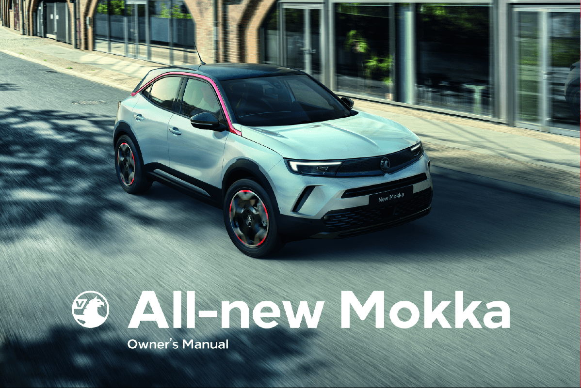
Vehicle specific data
Please enter your vehicle's data on
the previous page to keep it easily
accessible.
Please refer to the sections "Service
and maintenance", "Technical data",
the vehicle's identification plate and
national registration documents.
Introduction
Your vehicle is a designed
combination of advanced technology,
safety, environmental friendliness
and economy.
This Owner's Manual provides you
with all the necessary information to
enable you to drive your vehicle
safely and efficiently.
Some functions are only operational
when ignition is switched on, when
combustion engine is running or
when electric engine is ready.
Make sure your passengers are
aware of the possible risk of accident
and injury which may result from
improper use of the vehicle.
You must always comply with the
specific laws and regulations of the
country that you are in. These laws
may differ from the information in this
Owner's Manual.
Disregarding the description given in
this manual may affect your warranty.
When this Owner's Manual refers to a
workshop visit, we recommend your
Vauxhall Authorised Repairer.
All Vauxhall Authorised Repairers
provide first-class service at
reasonable prices. Experienced
mechanics trained by Vauxhall work
according to specific Vauxhall
instructions.
The customer literature pack should
always be kept ready to hand in the
vehicle.
Using this manual
● This manual describes all options
and features available for this
model. Certain descriptions,
including those for display and
menu functions, may not apply to
your vehicle due to model
variant, country specifications,
special equipment or
accessories.
● The table of contents at the
beginning of this manual and
within each section shows where
the information is located.
● The index will enable you to
search for specific information.
● This Owner's Manual depicts left-
hand drive vehicles. Operation is
similar for right-hand drive
vehicles.
● The Owner's Manual uses the
engine identifier code. The
corresponding sales designation
and engineering code can be
found in the section "Technical
data".
● Directional data, e.g. left or right,
or front or back, always relate to
the direction of travel.
● Displays may not support your
specific language.
● Display messages and interior
labelling are written in bold
letters.

4 Introduction
Propulsion types
Internal combustion engine (ICE)
vehicle
ICE vehicles are propelled by an
internal combustion engine - diesel or
petrol - only.
Battery electric vehicle (BEV)
BEVs are propelled by an electric
engine only.
The high voltage battery is charged
using a charging cable and
additionally by engine braking.
Danger, Warnings and
Cautions
9 Danger
Text marked 9 Danger provides
information on risk of fatal injury.
Disregarding this information may
endanger life.
9 Warning
Text marked 9 Warning provides
information on risk of accident or
injury. Disregarding this
information may lead to injury.
Caution
Text marked Caution provides
information on possible damage to
the vehicle. Disregarding this
information may lead to vehicle
damage.
Symbols
Page references are indicated with 3.
3 means "see page".
Page references and index entries
refer to the indented headings given
in the section table of content.
Thank you for choosing a Vauxhall.
We wish you many hours of
pleasurable driving.
Your Vauxhall Team

Introduction 5

6 Keys, doors and windows
Keys, doors and
windows
Keys, locks ..................................... 6
Keys ............................................ 6
Radio remote control ................... 7
Electronic key system .................. 8
Central locking system .............. 10
Automatic locking ...................... 14
Child locks ................................. 15
Doors ........................................... 16
Load compartment .................... 16
Vehicle security ............................ 17
Anti-theft locking system ........... 17
Anti-theft alarm system .............. 18
Immobiliser ................................ 19
Exterior mirrors ............................ 20
Convex shape ........................... 20
Electric adjustment .................... 20
Folding mirrors .......................... 20
Heated mirrors ........................... 21
Interior mirrors ............................. 21
Manual anti-dazzle .................... 22
Automatic anti-dazzle ................ 22
Windows ...................................... 22
Windscreen ............................... 22
Power windows ......................... 23
Heated rear window .................. 24
Sun visors .................................. 24
Roller blinds ............................... 25
Keys, locks
Keys
Caution
Do not attach heavy or bulky items
to the ignition key.
9 Danger
Never remove the key from
ignition switch during driving as
this will cause steering wheel lock.
Replacement keys
The key number is specified on a
detachable tag.
The key number must be quoted
when ordering replacement keys as it
is a component of the immobiliser
system.
Locks 3 276.
Central locking 3 10.
Starting the engine 3 166.
Radio remote control 3 7.
Keys, doors and windows 7
Electronic key 3 8.
The code number of the adapter for
the locking wheel nuts is specified on
a card. It must be quoted when
ordering a replacement adapter.
Wheel changing 3 268.
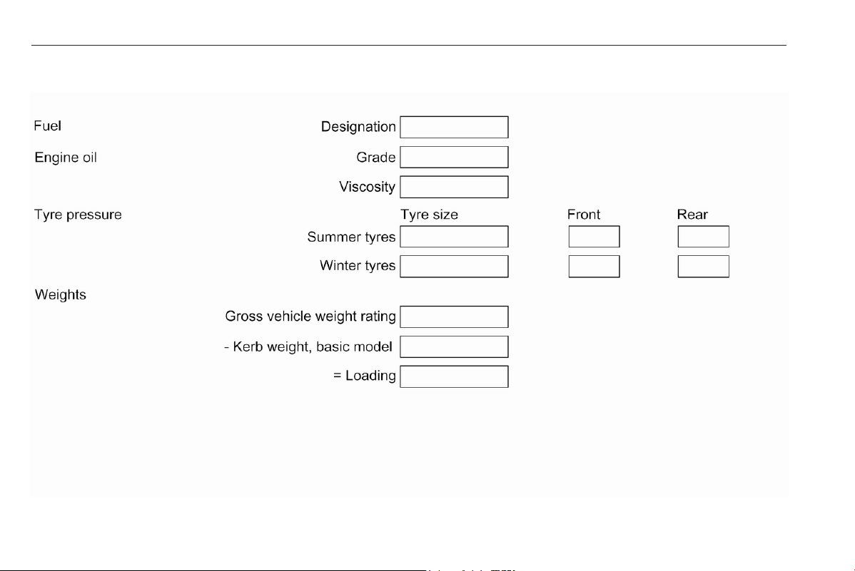
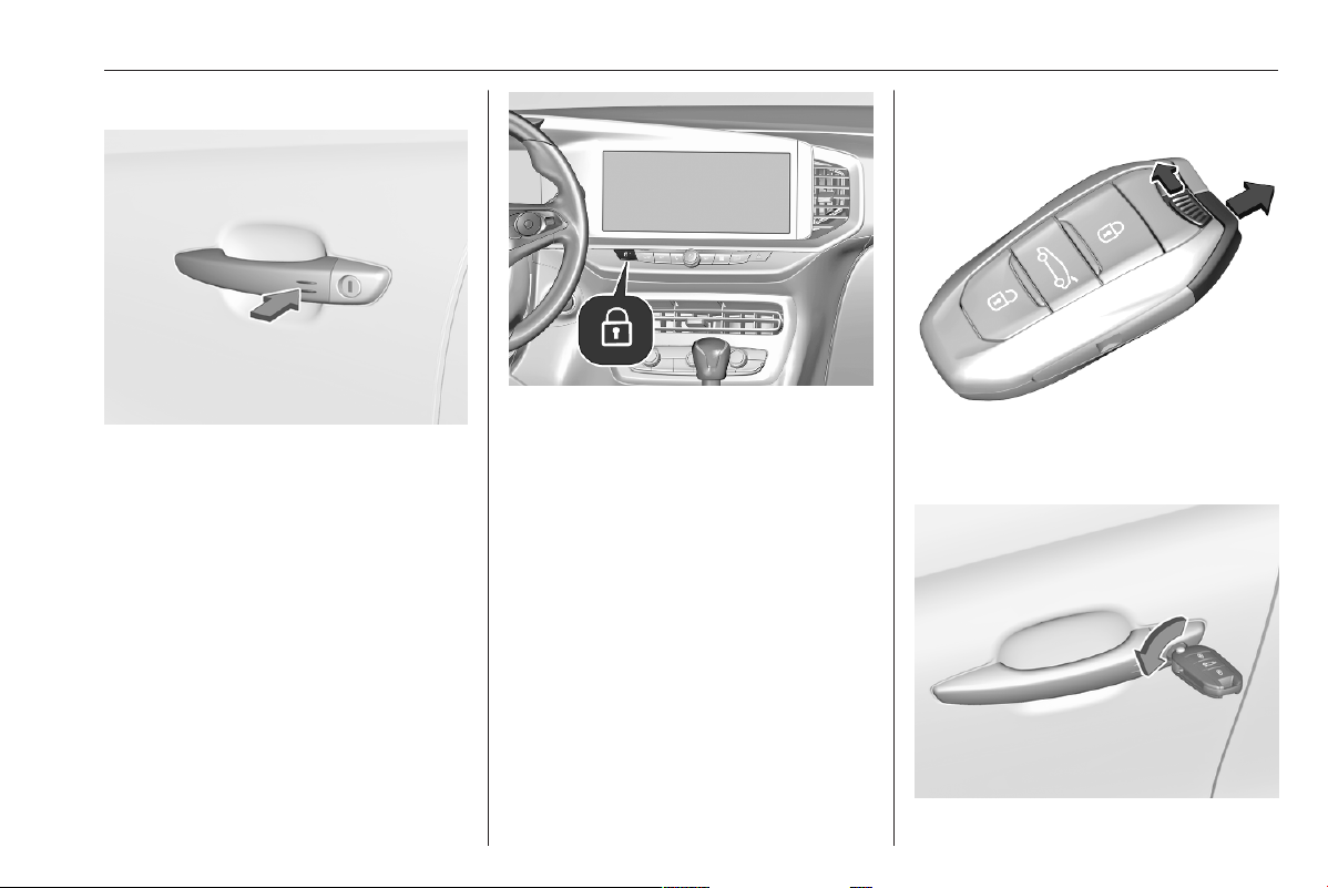
Key with foldaway key section
Press button to extend. To fold the
key, first press the button.
Lock cylinders
Designed to free-wheel if they are
forcefully rotated without the correct
key or if the correct key is not fully
inserted. To reset, insert the correct
key only half way and turn cylinder
until its slot is vertical, remove key
then re-insert it. If the cylinder still
free-wheels, insert the key only half
way and turn the key through 180°
and repeat operation.
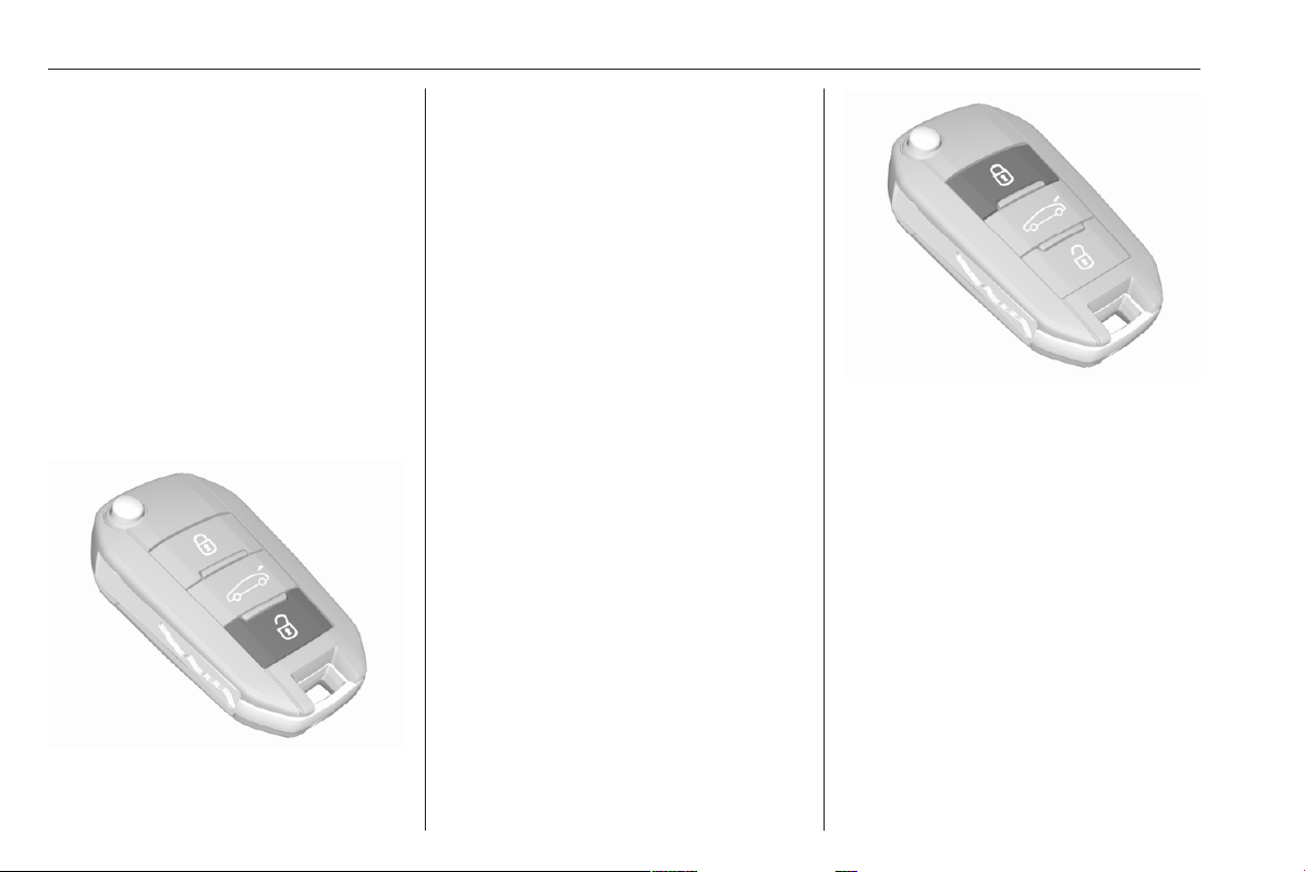
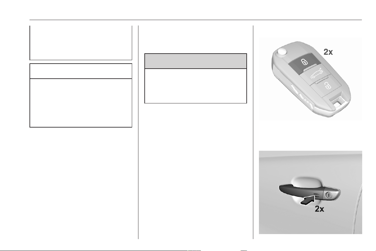
Radio remote control
a
: unlocks the vehicle
b
: locks the vehicle
?
: long press unlocks and
opens the tailgate
Enables operation of the following
functions via the use of the remote
control buttons:
● central locking system 3 10
● anti-theft locking system 3 17
● anti-theft alarm system 3 18
● tailgate unlocking
● power windows 3 23
● mirrors folding 3 20
● vehicle locator lighting 3 92
The remote control has a range of up
to 50 m, but may also be much less
due to external influences. The
hazard warning flashers confirm
operation.
Handle with care, protect from
moisture and high temperatures and
avoid unnecessary operation.
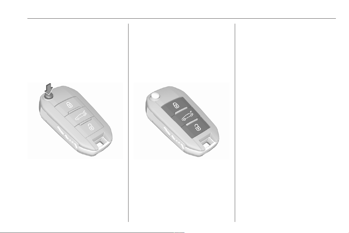
Replacing battery in radio remote
control
Replace the battery as soon as the
system no longer operates properly
or the range is reduced.
8 Keys, doors and windows
In the event of a discharged battery,
C illuminates and a warning
message is displayed in the Driver
Information Centre.
Driver Information Centre 3 80.
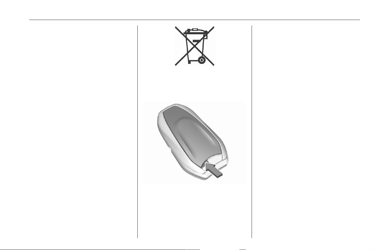
Batteries do not belong in household
waste. They must be disposed of at
an appropriate recycling collection
point.
1. Remove the back cover from the
remote control.
2. Extract the flat battery from its
location.
3. Replace battery with a battery of
the same type. Pay attention to
the installation position.
4. Clip the back cover in place.
Fault
If the central locking system cannot
be operated with the radio remote
control, the cause may be one of the
following:
● Fault in radio remote control.
● The battery voltage is too low.
● Overload of the central locking
system by operating at frequent
intervals, the power supply is
interrupted for a short time.
● Interference from higher-power
radio waves from other sources.
Manual unlocking 3 10.
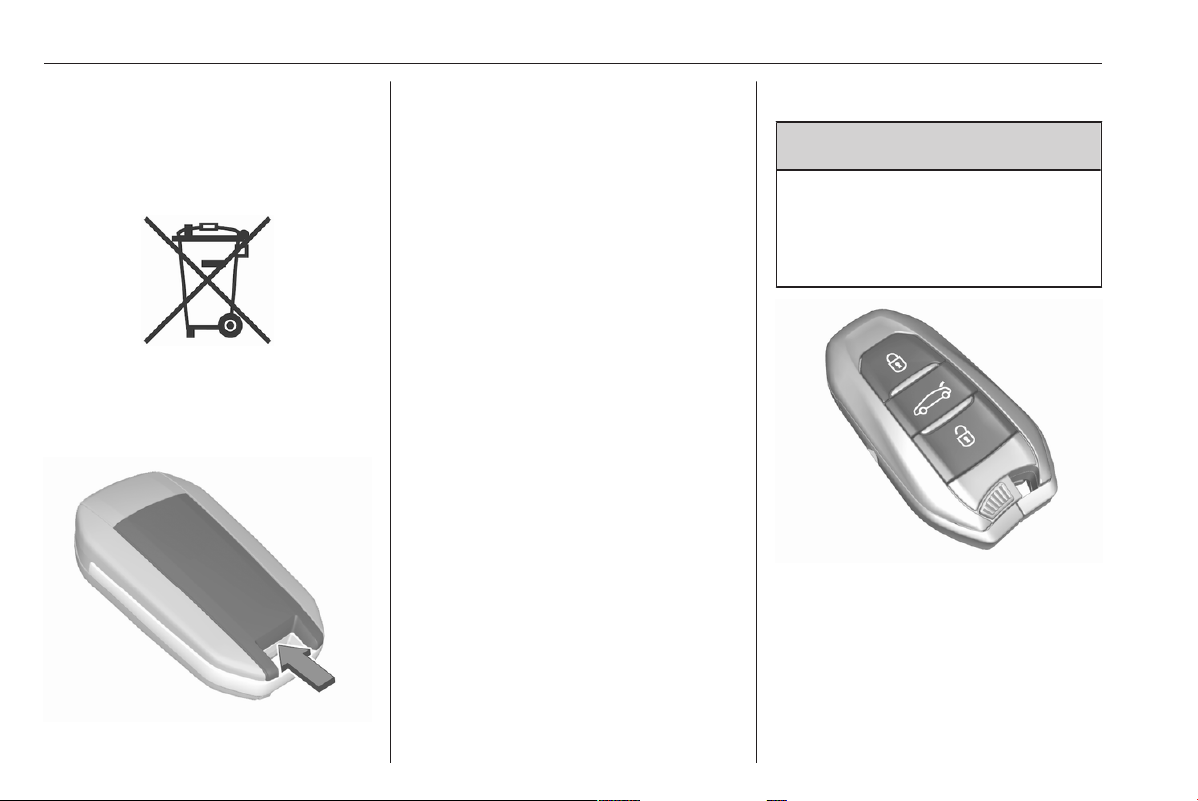
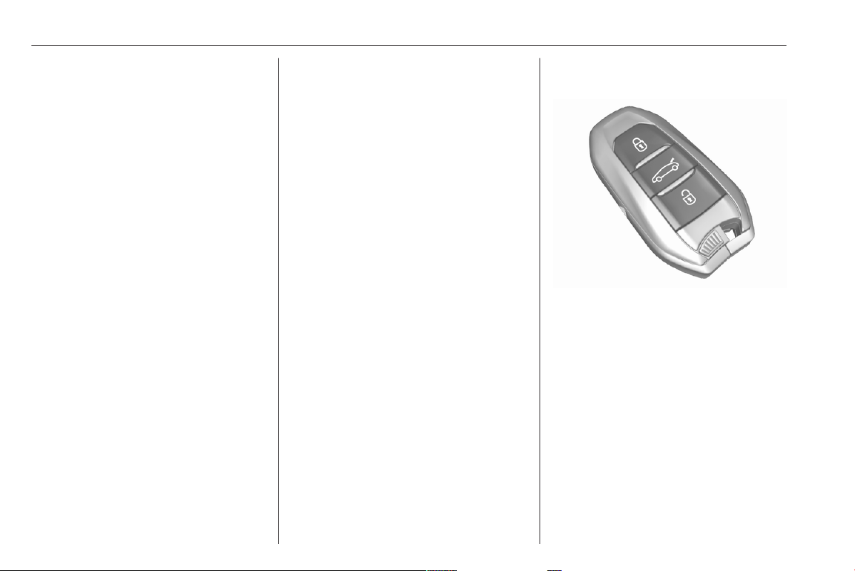
Electronic key system
9 Warning
The electronic key can affect a
pacemaker.
Keep the electronic key away from
the breast.
Enables a keyless operation of the
following functions:
● central locking system 3 10
● ignition switching on and starting
the engine 3 166
The electronic key simply needs to be
on the driver's person.
Keys, doors and windows 9
For reasons of security, the electronic
key may be equipped with a motion
sensor. If so, starting of the vehicle is
not possible when the electronic key
has not been moved for a certain
time. When trying to start the vehicle,
a corresponding message appears in
the Driver Information Centre. Move
the electronic key and try to start the
vehicle again.
Additionally, the electronic key
includes the functionality of the radio
remote control 3 7.
Handle with care, protect from
moisture and high temperatures and
avoid unnecessary operation.
Replacing battery in electronic
key
Replace the battery as soon as the
system no longer operates properly
or the range is reduced.
In the event of a discharged battery,
C illuminates and a warning
message is displayed in the Driver
Information Centre.
Driver Information Centre 3 80.
Batteries do not belong in household
waste. They must be disposed of at
an appropriate recycling collection
point.
1. Remove the back cover.
2. Extract the flat battery from its
location.
3. Replace battery with a battery of
the same type. Insert the battery
by pushing it against the contact
located in the corner and then
pressing it down. Pay attention to
the installation position.
4. Clip the back cover in place.
Fault
If the central locking cannot be
operated or the engine cannot be
started, the cause may be one of the
following:
● Fault in electronic key.
● Electronic key is out of reception
range.
● The battery voltage is too low.
● Overload of the central locking
system by operating at frequent
intervals, the power supply is
interrupted for a short time.
● Interference from higher-power
radio waves from other sources.
● Interference from electronic
devices such as smartphones or
laptops.
To rectify the cause of the fault,
change the position of the electronic
key.
Manual unlocking 3 10.
10 Keys, doors and windows
Central locking system
Unlocks and locks doors, load
compartment and fuel filler flap.
A pull on an interior door handle
opens the respective door.
Notice
In the event of an accident in which
airbags or belt pretensioners are
deployed, the vehicle is
automatically unlocked.
Remote control operation
Unlocking
Press a.
Notice
A short time after unlocking the
vehicle with the remote control, the
doors are locked automatically if no
door has been opened.
Unlocking mode can be set in the
vehicle personalisation menu in the
Info Display. Following settings are
selectable:
● All doors, load compartment and
fuel filler flap will be unlocked by
pressing a once.
● Only the driver's door and fuel
filler flap will be unlocked by
pressing a once. To additionally
unlock all doors and the load
compartment, press a twice.
Select the relevant setting in the
Vehicle personalisation.
Vehicle personalisation 3 81.
Locking
Close doors, load compartment and
fuel filler flap.
Press b.
If the vehicle is not closed properly,
the central locking system will not
work.
Operation of the central locking
system is confirmed by the hazard
warning flashers.
Keys, doors and windows 11
Load compartment
Press and hold ? to unlock.
Unlocking settings for the load
compartment can be set in the vehicle
personalisation:
● Only the load compartment will
be unlocked by pressing ?
once.
● All doors, load compartment and
fuel filler flap will be unlocked by
pressing ? once.
Depending on the chosen setting in
the vehicle personalisation, the load
compartment can be locked:
● by simply closing the opened
tailgate.
● by pressing b once on the
remote control with the tailgate
closed.
Select the relevant setting in the
vehicle personalisation.
Vehicle personalisation 3 81.
Unlocking the tailgate 3 16.
Confirmation
Operation of the central locking
system is confirmed by the hazard
warning flashers and an audible
chime.
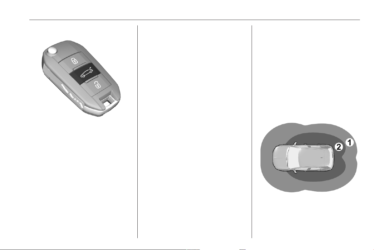
Electronic key system operation
The electronic key must be outside
the vehicle, within a range of approx.
1 m of the relevant door side.
This system allows automatic vehicle
locking and unlocking simply by
detection of the electronic key. The
electronic key must be outside the
vehicle.
Notice
If the vehicle is not closed properly
or the electronic key remains in the
vehicle, locking will not be permitted.
If the vehicle is equipped with an
anti-theft alarm system, a warning
chime sounds after a few seconds.
Notice
The electronic key may not operate
if placed close to electronic devices
such as mobile phones or laptop
computers.
● Zone 1: automatic locking on
leaving the vehicle
● Zone 2: automatic unlocking on
approaching the vehicle
12 Keys, doors and windows
Notice
If the electronic key remains for
more than 15 minutes in zone 1,
automatic unlocking is deactivated.
Unlock the vehicle by pressing a
or ? on the remote control or
touch the sensor of the driver's door
handle to unlock the vehicle.
Automatic locking and unlocking is
activated again.
Notice
A short time after automatic
unlocking, the vehicle is relocked if
no door has been opened.
Notice
If the ignition is switched off for more
than 9 days or the vehicle battery
has no sufficient charging, the
automatic function is disabled. Press
a or ? on the remote control or
touch the sensor of the driver's door
handle to unlock the vehicle.
In the event that the ignition is
switched off for more than 21 days,
the only way to unlock the vehicle is
by pressing a or ? on the remote
control.
Unlocking / locking
Unlocking / locking mode can be set
in the vehicle personalisation menu in
the Info Display. Following settings
are selectable:
● Only the driver's door and fuel
filler flap will be unlocked /
locked.
● All doors, load compartment and
fuel filler flap will be unlocked /
locked.
● Only the load compartment will
be unlocked / locked.
Vehicle personalisation 3 81.
Load compartment 3 16.
Operation with buttons on the
electronic key
The central locking system can also
be operated with the buttons on the
electronic key.
Press a or ? to unlock.
Press b to lock.
Remote control operation 3 10.
Keys, doors and windows 13
Driver's door handle
The central locking system can also
be operated by touching on the
sensor of the driver's door handle.
Touch the sensor of the drivers's door
handle to unlock or to lock.
Confirmation
Operation of central locking system is
confirmed by the hazard warning
flashers.
Central locking button
Locks or unlocks all doors, the load
compartment and fuel filler flap from
inside the passenger compartment.
Press b to lock. The LED in the button
illuminates.
Press b again to unlock. The LED in
the button extinguishes.
Operation with the key in case of
a central locking system fault
In case of a fault, e.g. vehicle battery
or remote control / electronic key
battery is discharged, the front door
can be locked or unlocked with the
mechanical key.
Manual unlocking
Electronic key: push the latch to
extract the integral key.
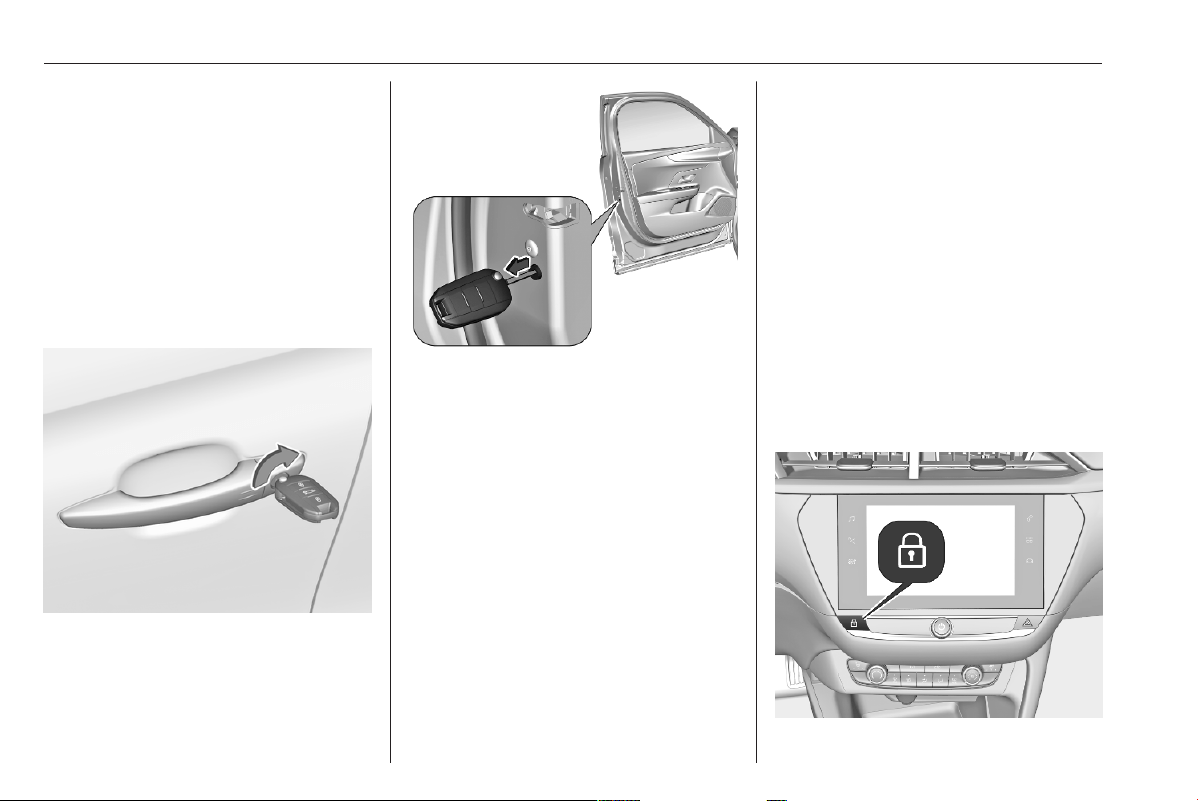
14 Keys, doors and windows
Manually unlock the left front door by
inserting and turning the key in the
lock cylinder.
The other doors can be opened by
pulling the interior handle. The load
compartment and fuel filler flap will
possibly not be unlocked.
By switching on the ignition, the anti-
theft locking system is deactivated.
Manual locking
Manually lock the front door by
inserting and turning the key in the
lock cylinder.
To lock the other doors, open the rear
doors. Ensure that child lock is
deactivated.
Insert key carefully and turn it to the
inner side of the doors.
Then, remove key.
Close the doors.
The fuel filler flap and tailgate are
possibly not locked.
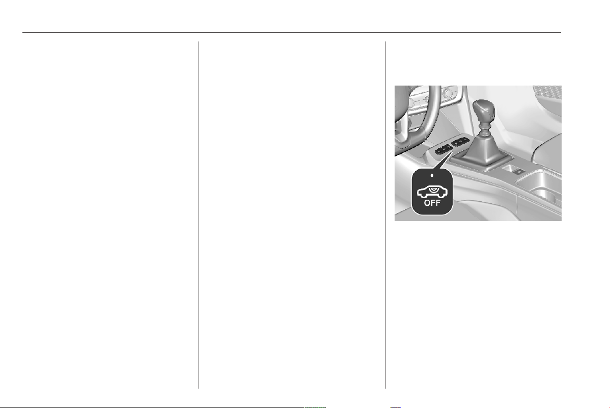
Automatic locking
Automatic locking after driving off
This system allows automatic locking
of the doors and tailgate as soon as
the speed of the vehicle exceeds a
certain speed.
If one of the doors or the tailgate is
open, the automatic central locking
does not take place. This is signalled
by the sound of the locks rebounding,
accompanied by illumination of P in
the Driver Information Centre, an
audible signal and the display of an
alert message.
Keys, doors and windows 15
This function can be activated or
deactivated at any time. With the
ignition on, press b until an audible
signal starts and a corresponding
message is displayed.
The state of the system stays in
memory when switching off the
ignition.
Automatic relock after unlocking
This feature automatically relocks the
vehicle a short time after unlocking
with the remote control or electronic
key, provided vehicle has not been
opened.
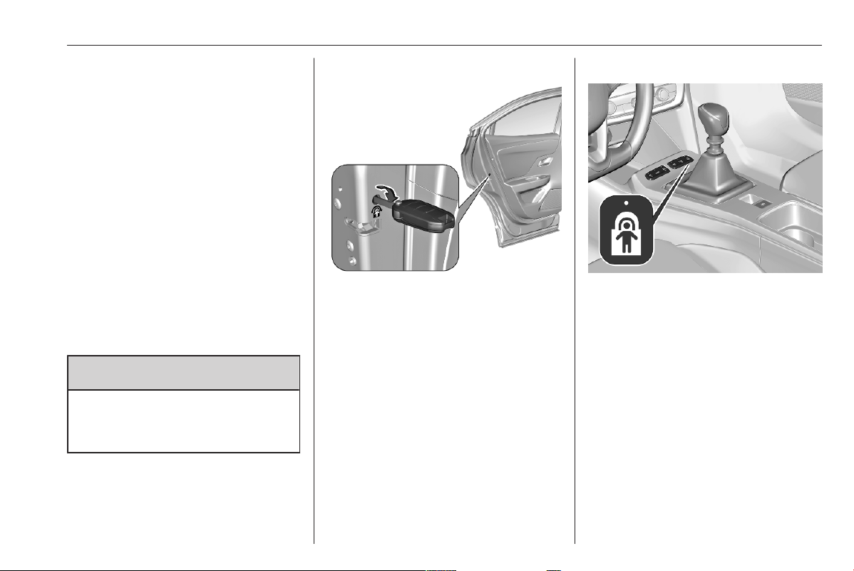
Child locks
9 Warning
Use the child locks whenever
children are occupying the rear
seats.
Mechanical child locks
Turn the red child lock in the rear door
inwards to the horizontal position by
using a key. The door cannot be
opened from the inside.
To deactivate, turn the child lock to
the vertical position.
Electric child locks
Remotely operated system to prevent
opening of the rear doors via the
interior door handles and the use of
the rear power windows.
Two versions are available.
Switching on
Press >. The LED in the button is
illuminated, accompanied by a
confirmation message. This LED
remains illuminated until the child lock
is switched off again.
Or
16 Keys, doors and windows
Press g.
Switching off
Press > again. The LED in the button
is extinguished, accompanied by a
confirmation message.
Or
Press g again.
Power windows 3 23.
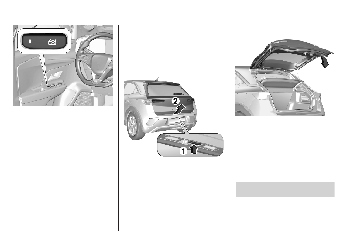
Doors
Load compartment
Tailgate
Opening
1. Press the tailgate button or press
long ? on the radio remote
control.
2. Open the tailgate.
Closing
Use the interior handle.
Do not push the tailgate button whilst
closing as this will open the tailgate
again.
Central locking system 3 10.
General hints for operating
tailgate
9 Danger
Do not drive with the tailgate open
or ajar, e.g. when transporting
bulky objects, since toxic exhaust
Keys, doors and windows 17
gases, which cannot be seen or
smelled, could enter the vehicle.
This can cause unconsciousness
and even death.
Caution
Before opening the tailgate, check
overhead obstructions, e.g. a
garage door, to avoid damage to
the tailgate. Always check the
moving area above and behind the
tailgate.
Notice
The installation of certain heavy
accessories onto the tailgate may
affect its ability to remain open.
Notice
At low outside temperatures the
tailgate may not open fully by itself.
In this case lift the tailgate manually
to its normal end position.
Vehicle security
Anti-theft locking system
9 Warning
Do not use the system if there are
people in the vehicle! The doors
cannot be unlocked from the
inside.
The system deadlocks all the doors.
All doors must be closed otherwise
the system cannot be activated.
Unlocking the vehicle disables the
mechanical anti-theft locking system.
This is not possible with the central
locking button.
Activating
Press b on the radio remote control
or touch the sensor of the driver's
door handle twice within 3 seconds.
18 Keys, doors and windows
Anti-theft alarm system
The anti-theft alarm system is
combined with the central locking
system.
It monitors:
● doors, tailgate, bonnet
● passenger compartment
including adjoining load
compartment
● vehicle inclination, e.g. if it is
raised
● ignition
Activation
All doors, the load compartment and
the engine compartment must be
closed.
The electronic key must not remain in
the vehicle.
The system is self-activated
45 seconds after locking the vehicle.
If a door, the tailgate or the bonnet is
not properly closed, the vehicle is not
locked. However, the anti-theft alarm
is self-activated after 45 seconds.
Notice
The automatic vehicle locking
function does not activate the anti-
theft alarm system.
To activate the anti-theft alarm
system, lock the vehicle by using the
radio remote control or by touching
the sensor on the driver's door
handle.
Central locking system 3 10.
Notice
Changes to the vehicle interior such
as the use of seat covers and open
windows, could impair the function
of passenger compartment
monitoring.
Activation without monitoring of
passenger compartment and
vehicle inclination
Switch off the monitoring of
passenger compartment and vehicle
inclination when animals are being
left in the vehicle, because of high
volume ultrasonic signals or
movements triggering the alarm.
Also, switch off when the vehicle is on
a ferry or train.
1. Close tailgate, bonnet, windows.
2. Switch off ignition and press !
within 10 seconds until the LED in
the button ! illuminates.

Keys, doors and windows 19
3. Leave the vehicle and close the
doors.
4. Activate the anti-theft alarm
system.
Indication
LED in the ! button flashes if the
anti-theft alarm system is activated.
The hazard warning lights illuminates
for a few seconds.
Deactivation
Unlocking the vehicle deactivates the
anti-theft alarm system.
The system is not deactivated by
unlocking the front door with the key
or with the central locking button in
the passenger compartment.
Alarm
When triggered, the alarm siren
sounds and the hazard warning lights
flash simultaneously. The number
and duration of alarm signals are
stipulated by legislation.
The anti-theft alarm can be
deactivated by pressing a or
switching on the ignition.
A triggered alarm, which has not been
interrupted by the driver, will be
indicated by the LED in the
button !. The LED will flash quickly
the next time the vehicle is unlocked.
If the vehicle battery has been
reconnected (e.g. after maintenance
work), wait for 10 minutes to restart
the engine.
Fault
If the LED in the button !
illuminates permanently when
switching on the ignition, seek the
assistance of a workshop.
Locking the vehicle without
activation of the anti-theft alarm
Lock the vehicle by locking the front
door with the key.
Immobiliser
The system is part of the ignition
switch and checks whether the
vehicle is allowed to be started with
the key being used.
The immobiliser is activated
automatically.
Notice
Radio Frequency Identification
(RFID) tags may cause interference
with the key. Do not have it placed
near the key when starting the
vehicle.
Notice
The immobiliser does not lock the
doors. Always lock the vehicle after
leaving it 3 10.
Switch on the anti-theft alarm
system 3 18.
Emergency operation of electronic
key 3 164.
20 Keys, doors and windows
Exterior mirrors
Convex shape
The shape of the mirror makes
objects appear smaller, which will
affect the ability to estimate
distances.
Side blind spot alert 3 216.
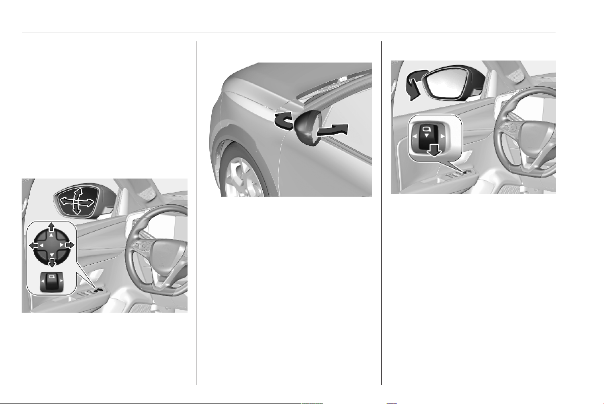
Electric adjustment
Select the relevant exterior mirror by
pushing C to the left or right.
Then swivel the control to adjust the
mirror.
Folding mirrors
For pedestrian safety, the exterior
mirrors will swing out of their normal
mounting position if they are struck
with sufficient force. Reposition the
mirror by applying slight pressure to
the mirror housing.
Manual electric folding
Move C to the centre position.
Pull C rearwards. Both exterior
mirrors are folded.
Pull C rearwards again. Both
exterior mirrors return to their original
position.
If an electrically folded mirror is
manually unfolded, pulling C
rearwards will only unfold the other
mirror electrically.
Keys, doors and windows 21
Automatic electric folding
When the vehicle is unlocked, the
mirrors swing to their normal
mounting position. When the vehicle
is locked, the mirrors are folded down.
To enable or disable automatic
folding of the exterior mirrors, consult
a workshop.
Heated mirrors
Operated by pressing
f.
The heating switches off
automatically after a certain time
depending on the outside
temperature.
Heated rear window 3 24.
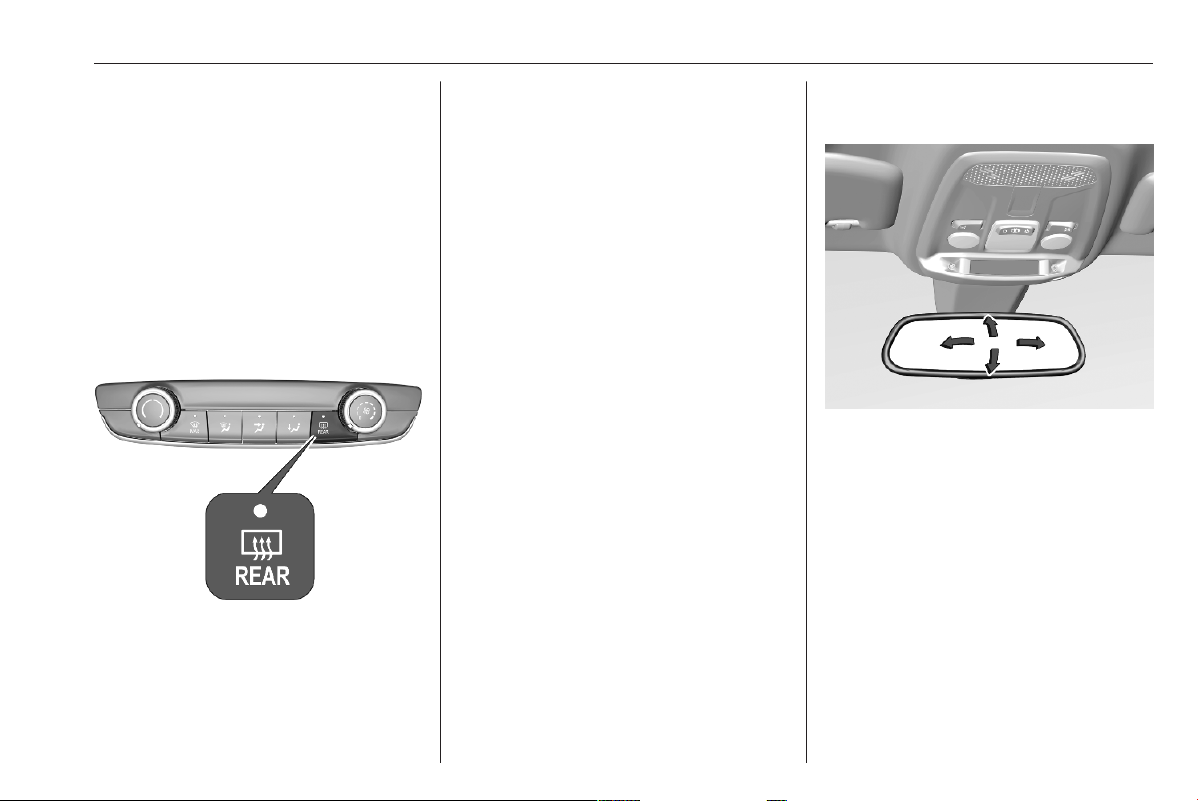
Interior mirrors
To adjust the mirror, move the mirror
housing in the desired direction.
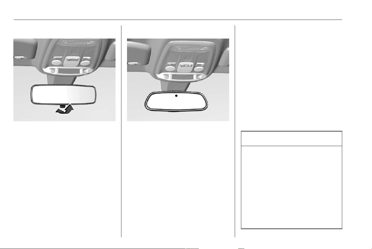
22 Keys, doors and windows
Manual anti-dazzle
To reduce dazzle, adjust the lever on
the underside of the mirror housing.
Automatic anti-dazzle
Dazzle from following vehicles is
automatically reduced, when driving
in the dark.
Windows
Windscreen
Windscreen stickers
Do not attach stickers such as toll
road stickers or similar on the
windscreen in the area of the interior
mirror. Otherwise the detection zone
of the sensor and the view area of the
camera in the mirror housing could be
restricted.
Windscreen replacement
Caution
If the vehicle has a front-looking
camera sensor for the driver
assistance systems, it is very
important that any windscreen
replacement is performed
accurately according to Vauxhall
specifications. Otherwise, these
systems may not work properly
and there is a risk of unexpected
behaviour and / or messages from
these systems.
Keys, doors and windows 23
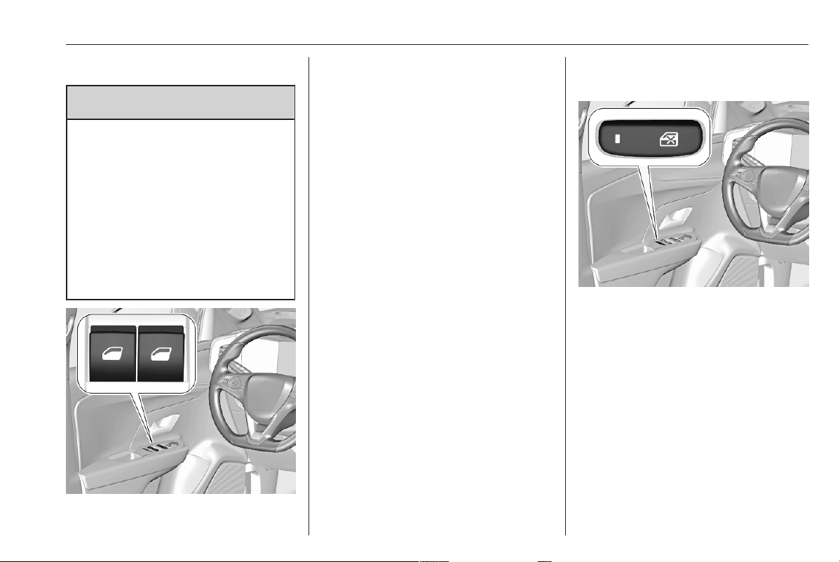
Power windows
9 Warning
Take care when operating the
power windows. Risk of injury,
particularly to children.
If there are children on the rear
seats, switch on the child safety
system for the power windows.
Keep a close watch on the
windows when closing them.
Ensure that nothing becomes
trapped in them as they move.
Operate the switch for the respective
window by pushing to open or pulling
to close.
Pushing or pulling gently to the first
detent: window moves up or down as
long as the switch is operated.
Pushing or pulling firmly to the second
detent then releasing: window moves
up or down automatically with safety
function enabled. To stop movement,
operate the switch once more in the
same direction.
Safety function
If the window glass encounters
resistance of the window during
automatic closing, it is immediately
stopped and opened again.
Child safety system for rear
windows
Press g to deactivate rear door
power windows; the LED illuminates.
To activate, press g again.
Depending on version, additionally
operation of electric child locks 3 15.
Closing windows from outside
The windows can be closed remotely
from outside the vehicle.
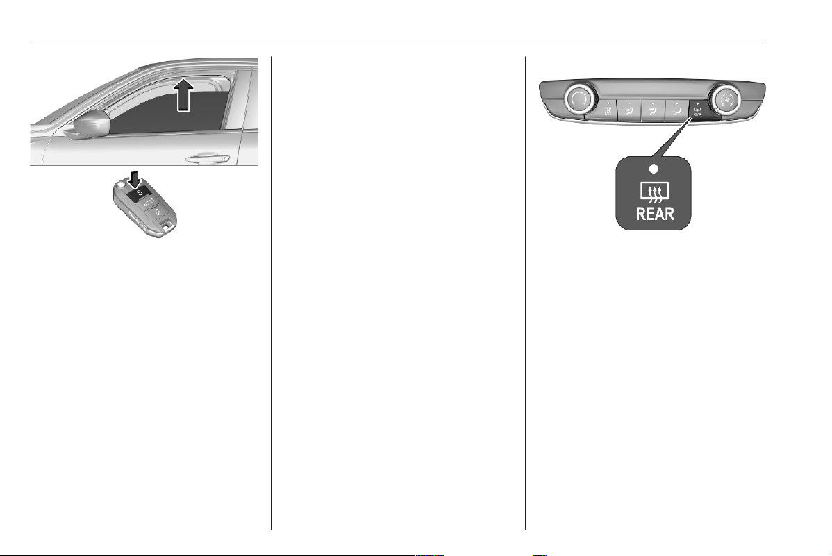
24 Keys, doors and windows
Press and hold b to close windows.
If the windows are fully closed, the
hazard warning lights will flash twice.
Overload
If the windows are repeatedly
operated within short intervals, the
window operation is disabled for
some time.
Initialising the power windows
Activate the window electronics as
follows:
1. Close doors.
2. Switch on ignition.
3. Open the window completely by
using the switch.
4. Pull the switch repeatedly until the
window is completely closed and
keep pushing for additional
1 second. Note that the window
closes only a few centimetres
after each pull of the switch.
5. Repeat for each window.
Heated rear window
Operated by pressing f together
with heated exterior mirrors.
Heating is switched off automatically
after a short time.
Depending on climate control system,
f is located at a different position.
Heated mirrors 3 21.
Sun visors
The sun visors can be folded down or
swivelled to the side to prevent
dazzling.
If the sun visors have integral mirrors,
the mirror covers should be closed
when driving.
A ticket holder is located on the
backside of the sun visor.
Keys, doors and windows 25
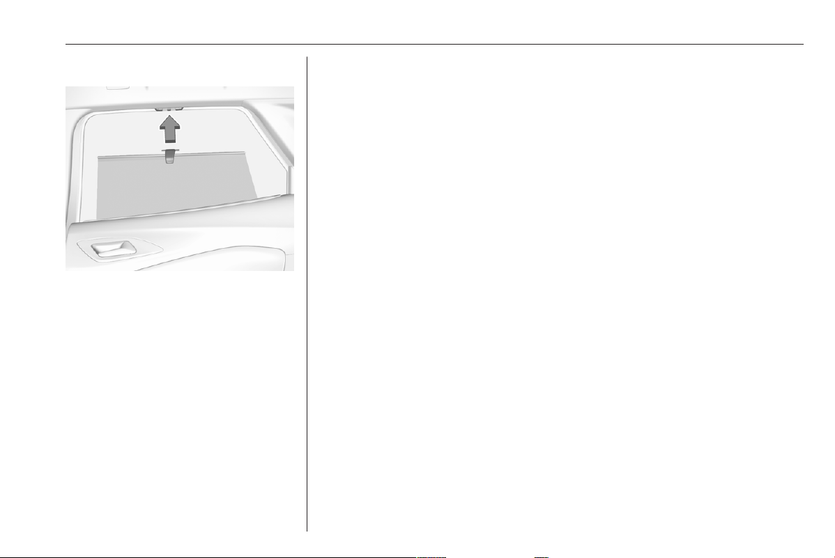
Roller blinds
To reduce sunlight at the rear seats,
pull the blind upwards using the grip
and engage it at the top of the door
frame.
26 Seats, restraints
Seats, restraints
Head restraints ............................ 26
Front seats ................................... 27
Seat position .............................. 27
Manual seat adjustment ............ 28
Power seat adjustment .............. 29
Armrest ...................................... 29
Heating ...................................... 30
Massage .................................... 30
Seat belts ..................................... 30
Three-point seat belt ................. 31
Airbag system .............................. 33
Front airbag system ................... 36
Side airbag system .................... 36
Curtain airbag system ............... 37
Airbag deactivation .................... 38
Child restraints ............................. 39
Child restraint systems .............. 39
Child restraint installation
locations ................................... 43
Head restraints
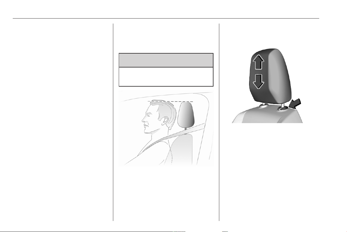
Position
9 Warning
Only drive with the head restraint
set to the proper position.
The upper edge of the head restraint
should be at upper head level. If this
is not possible for extremely tall
people, set to highest position, and
set to lowest position for small people.
Height adjustment
Head restraints on front seats
Pull the head restraint upwards or
press the catch to release and push
the head restraint downwards.
Seats, restraints 27
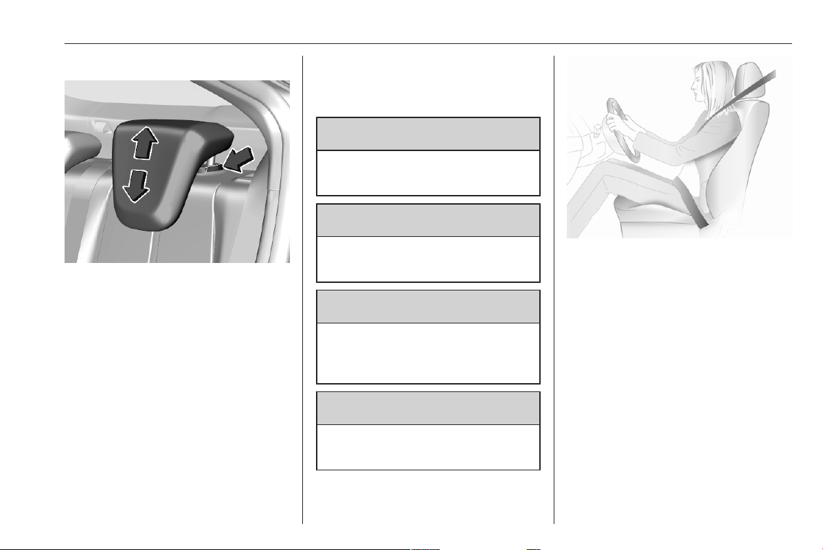
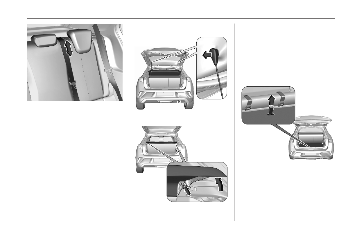
Head restraints on rear seats
Pull the head restraint upwards or
press the catch to release and push
the head restraint downwards.
Removal
Press catch, pull the respective head
restraint upwards and remove.
Front seats
Seat position
9 Warning
Only drive with the seat correctly
adjusted.
9 Warning
Never adjust seats while driving as
they could move uncontrollably.
9 Danger
Do not sit closer than 25 cm to the
steering wheel, to permit safe
airbag deployment.
9 Warning
Never store any objects under the
seats.
● Sit with buttocks as far back
against the backrest as possible.
Adjust the distance between the
seat and the pedals so that legs
are slightly angled when pressing
the pedals. Slide the front
passenger seat as far back as
possible.
● Set seat height high enough to
have a clear field of vision on all
sides and of all display
instruments. There should be at
least one hand of clearance
between head and the roof
frame. Your thighs should rest
lightly on the seat without
pressing into it.
28 Seats, restraints
● Adjust the head restraint so that
its upper edge is at upper head
level.
● Sit with shoulders as far back
against the backrest as possible.
Set the backrest rake so that it is
possible to easily reach the
steering wheel with arms slightly
bent. Maintain contact between
shoulders and the backrest when
turning the steering wheel. Do
not angle the backrest too far
back. We recommend a
maximum rake of approx. 25°.
● Adjust seat and steering wheel in
a way that the wrist rests on top
of the steering wheel while the
arm is fully extended and
shoulders are on the backrest.
● Adjust the lumbar support so that
it supports the natural shape of
the spine.
Head restraint adjustment 3 26.
Steering wheel adjustment 3 57.
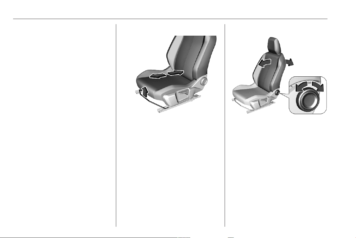
Manual seat adjustment
Drive only with engaged seats and
backrests.
Longitudinal adjustment
Pull handle, slide seat, release
handle. Try to move the seat back and
forth to ensure that the seat is locked
in place.
Backrest inclination
Turn handwheel. Do not lean on
backrest when adjusting.
Seats, restraints 29
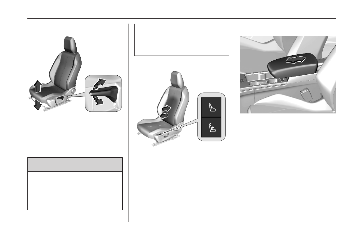
Seat height
Lever pumping motion
up : seat higher
down : seat lower
Power seat adjustment
9 Warning
Care must be taken when
operating the power seats. There
is a risk of injury, particularly for
children. Objects could become
trapped.
Keep a close watch on the seats
when adjusting them. Vehicle
passengers should be informed
accordingly.
Lumbar support
Press * or '.
*
: more lumbar support
'
: less lumbar support
Armrest
The armrest can be adjusted.
Storage compartment 3 47.
30 Seats, restraints
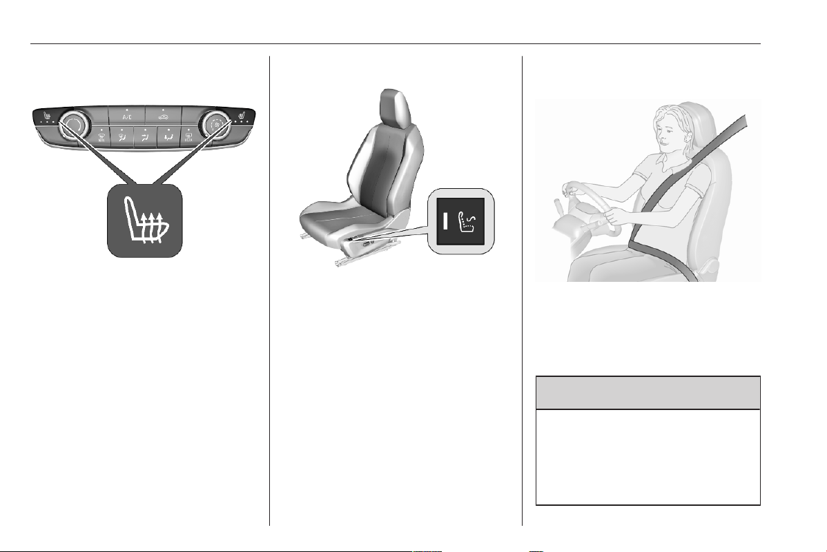
Heating
Adjust heating to the desired setting
by pressing " for the respective seat
one or more times. The control
indicator in the button indicates the
setting.
The heating works only when the
outside temperature is below 20 °C.
Prolonged use of the highest setting
for people with sensitive skin is not
recommended.
Stop-start system 3 167.
Massage
Activate the back massage function
by pressing K. The LED in the button
illuminates to indicate activation.
The massage function is activated for
a period of 1 hour. During this time,
massage is performed in six cycles
with breaks in between.
Pressing K once more deactivates
massage function. The LED goes off.
Stop-start system 3 167.
Seat belts
The seat belts are locked during
heavy acceleration or deceleration of
the vehicle, holding the occupants in
the seat position. Therefore the risk of
injury is considerably reduced.
9 Warning
Fasten seat belt before each trip.
In the event of an accident, people
not wearing seat belts endanger
their fellow occupants and
themselves.
Seats, restraints 31
Seat belts are designed to be used by
only one person at a time.
Child restraint system 3 39.
Periodically check all parts of the belt
system for damage, soiling and
proper functionality.
Have damaged components
replaced. After an accident, have the
seat belts and triggered belt
pretensioners replaced by a
workshop.
Notice
Make sure that the belts are not
damaged by shoes or sharp-edged
objects or are trapped. Prevent dirt
from getting into the belt retractors.
Notice
Use the belt buckle intended for the
respective seat belt when fastening
in order to ensure proper
functionality.
Seat belt reminder
Each seat is equipped with a seat belt
reminder, indicated by a control
indicator a for the respective seat in
the roof console 3 69.
Belt force limiters
Stress on the body is reduced by the
gradual release of the belt during a
collision.
Belt pretensioners
In the event of a head-on, rear-end or
side-on collision of a certain severity,
the front seat belts and the outer rear
seat belts are tightened.
9 Warning
Incorrect handling (e.g. removal or
fitting of belts) can trigger the belt
pretensioners.
Deployment of the belt pretensioners
is indicated by continuous illumination
of control indicator d 3 70.
Triggered belt pretensioners must be
replaced by a workshop. Belt
pretensioners can only be triggered
once.
Notice
Do not affix or install accessories or
other objects that may interfere with
the operation of the belt
pretensioners. Do not make any
modifications to belt pretensioner
components as this will invalidate
the operating permit of your vehicle.
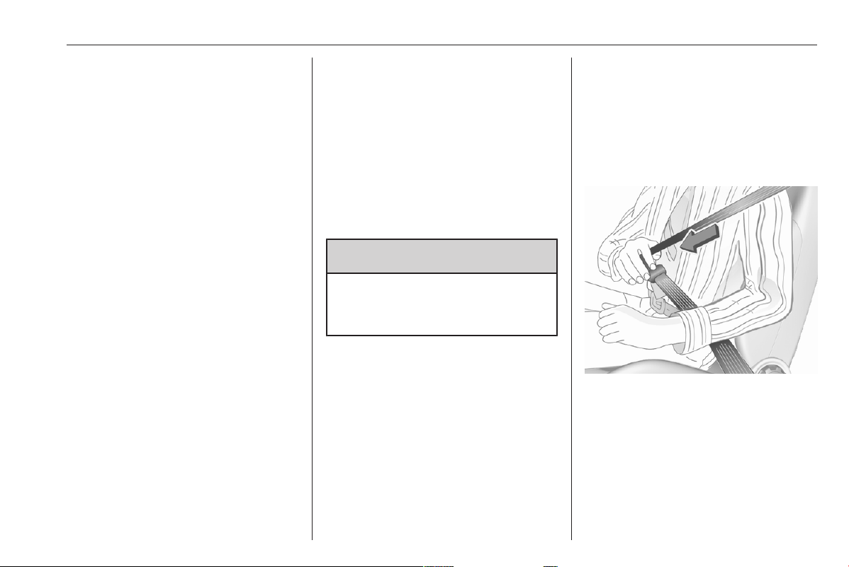
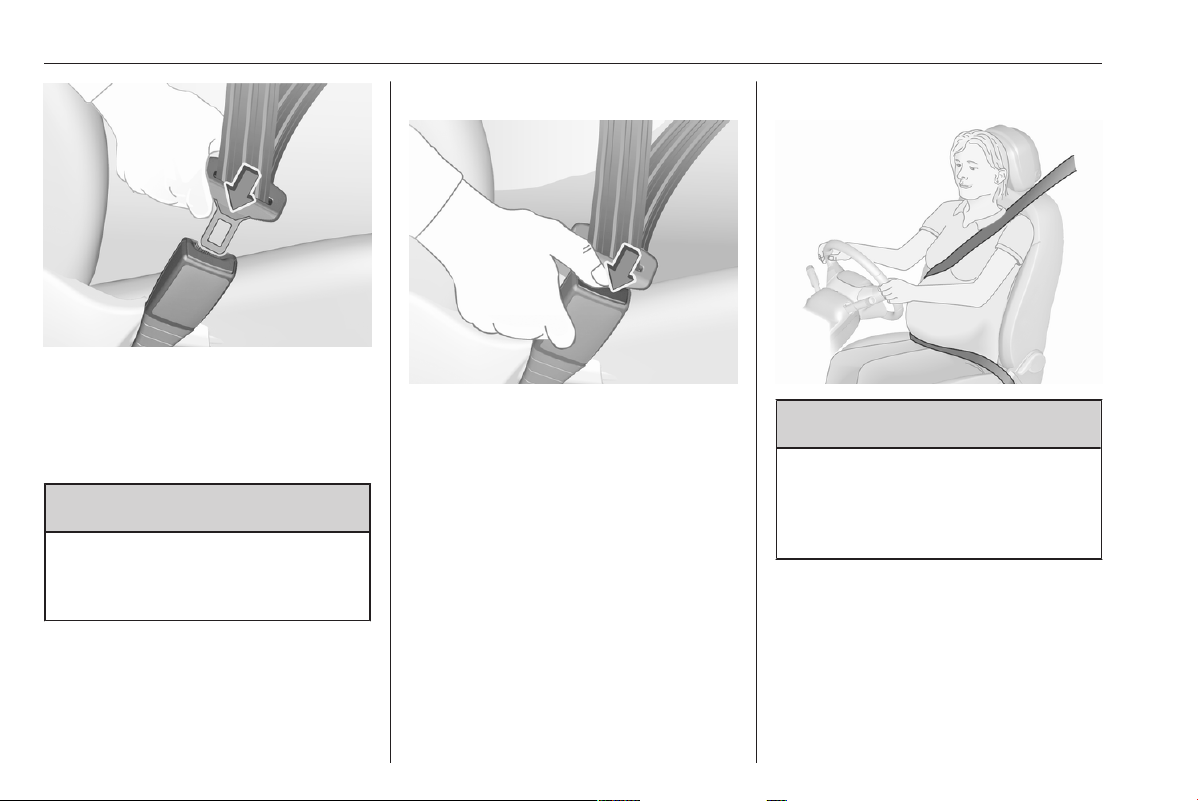
Three-point seat belt
Fasten
Withdraw the seat belt from the
retractor, guide it untwisted across
the body and insert the latch plate into
the buckle. Make sure the seat belt
lies across the shoulder and fits tightly
to the body while driving.
32 Seats, restraints
Loose or bulky clothing prevents the
seat belt from fitting snugly. Do not
place objects such as handbags or
mobile phones between the seat belt
and your body.
9 Warning
The seat belt must not rest against
hard or fragile objects in the
pockets of your clothing.
Seat belt reminder a 3 69.
Unfasten
To release seat belt, press red button
on seat belt buckle and guide the seat
belt back.
Using seat belts while pregnant
9 Warning
The lap belt must be positioned as
low as possible across the pelvis
to prevent pressure on the
abdomen.
Seats, restraints 33
Airbag system
The airbag system consists of a
number of individual systems.
When triggered, the airbags inflate
within milliseconds. They also deflate
so quickly that it is often unnoticeable
during the collision.
9 Warning
The airbag system deploys in an
explosive manner, repairs must be
performed by skilled personnel
only.
9 Warning
Adding accessories that change
the vehicle's frame, bumper
system, height, front end or side
sheet metal, may keep the airbag
system from working properly. The
operation of the airbag system can
also be affected by changing any
parts of the front seats, seat belts,
airbag sensing and diagnostic
module, steering wheel,
instrument panel, inner door seals
including the speakers, any of the
airbag modules, ceiling or pillar
trim, front sensors, side impact
sensors or airbag wiring.
9 Warning
Keep the area in which the airbag
inflates clear of obstructions.
Notice
The airbag systems and belt
pretensioner control electronics are
located in the centre console area.
Do not put any magnetic objects in
this area.
Do not affix any objects onto the
airbag covers and do not cover them
with other materials. Have damaged
covers replaced by a workshop.
Each airbag is triggered only once.
Have deployed airbags replaced by
a workshop. Furthermore, it may be
necessary to have the steering
wheel, the instrument panel, parts of
the panelling, the door seals,
handles and the seats replaced.
Do not make any modifications to
the airbag system as this will
invalidate the vehicle operating
permit.
Control indicator v for airbag systems
3 70.
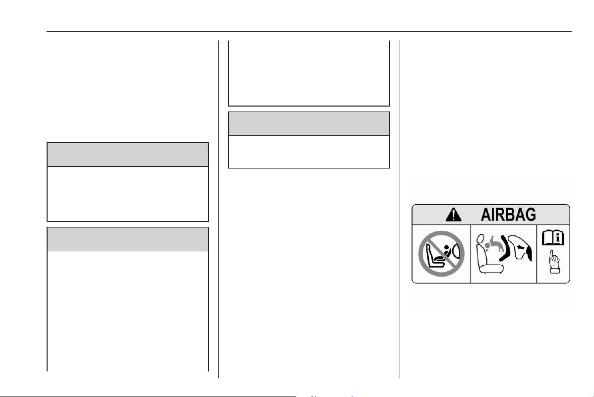
Child restraint systems on front
passenger seat with airbag
systems
Warning according to ECE R94.03:
EN: NEVER use a rearward-facing
child restraint on a seat protected by
an ACTIVE AIRBAG in front of it;
DEATH or SERIOUS INJURY to the
CHILD can occur.

34 Seats, restraints
DE: Nach hinten gerichtete
Kindersitze NIEMALS auf einem Sitz
verwenden, der durch einen davor
befindlichen AKTIVEN AIRBAG
geschützt ist, da dies den TOD oder
SCHWERE VERLETZUNGEN DES
KINDES zur Folge haben kann.
FR: NE JAMAIS utiliser un siège
d'enfant orienté vers l'arrière sur un
siège protégé par un COUSSIN
GONFLABLE ACTIF placé devant lui,
sous peine d'infliger des
BLESSURES GRAVES, voire
MORTELLES à l'ENFANT.
ES: NUNCA utilice un sistema de
retención infantil orientado hacia
atrás en un asiento protegido por un
AIRBAG FRONTAL ACTIVO. Peligro
de MUERTE o LESIONES GRAVES
para el NIÑO.
RU: ЗАПРЕЩАЕТСЯ
устанавливать детское
удерживающее устройство лицом
назад на сиденье автомобиля,
оборудованном фронтальной
подушкой безопасности, если
ПОДУШКА НЕ ОТКЛЮЧЕНА! Это
может привести к СМЕРТИ или
СЕРЬЕЗНЫМ ТРАВМАМ
РЕБЕНКА.
NL: Gebruik NOOIT een achterwaarts
gericht kinderzitje op een stoel met
een ACTIEVE AIRBAG ervoor, om
DODELIJK of ERNSTIG LETSEL van
het KIND te voorkomen.
DA: Brug ALDRIG en bagudvendt
autostol på et forsæde med AKTIV
AIRBAG, BARNET kan komme i
LIVSFARE eller komme ALVORLIGT
TIL SKADE.
SV: Använd ALDRIG en bakåtvänd
barnstol på ett säte som skyddas med
en framförvarande AKTIV AIRBAG.
DÖDSFALL eller ALLVARLIGA
SKADOR kan drabba BARNET.
FI: ÄLÄ KOSKAAN sijoita taaksepäin
suunnattua lasten turvaistuinta
istuimelle, jonka edessä on
AKTIIVINEN TURVATYYNY, LAPSI
VOI KUOLLA tai VAMMAUTUA
VAKAVASTI.
NO: Bakovervendt
barnesikringsutstyr må ALDRI brukes
på et sete med AKTIV
KOLLISJONSPUTE foran, da det kan
føre til at BARNET utsettes for
LIVSFARE og fare for ALVORLIGE
SKADER.
PT: NUNCA use um sistema de
retenção para crianças voltado para
trás num banco protegido com um
AIRBAG ACTIVO na frente do
mesmo, poderá ocorrer a PERDA DE
VIDA ou FERIMENTOS GRAVES na
CRIANÇA.
IT: Non usare mai un sistema di
sicurezza per bambini rivolto
all'indietro su un sedile protetto da
AIRBAG ATTIVO di fronte ad esso:
pericolo di MORTE o LESIONI
GRAVI per il BAMBINO!
EL: ΠΟΤΕ μη χρησιμοποιείτε παιδικό
κάθισμα ασφαλείας με φορά προς τα
πίσω σε κάθισμα που προστατεύεται
από μετωπικό ΕΝΕΡΓΟ ΑΕΡΟΣΑΚΟ,
διότι το παιδί μπορεί να υποστεί
ΘΑΝΑΣΙΜΟ ή ΣΟΒΑΡΟ
ΤΡΑΥΜΑΤΙΣΜΟ.
PL: NIE WOLNO montować fotelika
dziecięcego zwróconego tyłem do
kierunku jazdy na fotelu, przed
którym znajduje się WŁĄCZONA
PODUSZKA POWIETRZNA.
Niezastosowanie się do tego

Seats, restraints 35
zalecenia może być przyczyną
ŚMIERCI lub POWAŻNYCH
OBRAŻEŃ u DZIECKA.
TR: Arkaya bakan bir çocuk emniyet
sistemini KESİNLİKLE önünde bir
AKTİF HAVA YASTIĞI ile
korunmakta olan bir koltukta
kullanmayınız. ÇOCUK ÖLEBİLİR
veya AĞIR ŞEKİLDE
YARALANABİLİR.
UK: НІКОЛИ не використовуйте
систему безпеки для дітей, що
встановлюється обличчям назад,
на сидінні з УВІМКНЕНОЮ
ПОДУШКОЮ БЕЗПЕКИ, інакше це
може призвести до СМЕРТІ чи
СЕРЙОЗНОГО ТРАВМУВАННЯ
ДИТИНИ.
HU: SOHA ne használjon hátrafelé
néző biztonsági gyerekülést előlről
AKTÍV LÉGZSÁKKAL védett ülésen,
mert a GYERMEK HALÁLÁT vagy
KOMOLY SÉRÜLÉSÉT okozhatja.
HR: NIKADA nemojte koristiti sustav
zadržavanja za djecu okrenut prema
natrag na sjedalu s AKTIVNIM
ZRAČNIM JASTUKOM ispred njega,
to bi moglo dovesti do SMRTI ili
OZBILJNJIH OZLJEDA za DIJETE.
SL: NIKOLI ne nameščajte otroškega
varnostnega sedeža, obrnjenega v
nasprotni smeri vožnje, na sedež z
AKTIVNO ČELNO ZRAČNO
BLAZINO, saj pri tem obstaja
nevarnost RESNIH ali SMRTNIH
POŠKODB za OTROKA.
SR: NIKADA ne koristiti bezbednosni
sistem za decu u kome su deca
okrenuta unazad na sedištu sa
AKTIVNIM VAZDUŠNIM
JASTUKOM ispred sedišta zato što
DETE može da NASTRADA ili da se
TEŠKO POVREDI.
MK: НИКОГАШ не користете детско
седиште свртено наназад на
седиште заштитено со АКТИВНО
ВОЗДУШНО ПЕРНИЧЕ пред него,
затоа што детето може ДА ЗАГИНЕ
или да биде ТЕШКО ПОВРЕДЕНО.
BG: НИКОГА не използвайте
детска седалка, гледаща назад,
върху седалка, която е защитена
чрез АКТИВНА ВЪЗДУШНА
ВЪЗГЛАВНИЦА пред нея - може да
се стигне до СМЪРТ или
СЕРИОЗНО НАРАНЯВАНЕ на
ДЕТЕТО.
RO: Nu utilizaţi NICIODATĂ un scaun
pentru copil îndreptat spre partea din
spate a maşinii pe un scaun protejat
de un AIRBAG ACTIV în faţa sa;
acest lucru poate duce la DECESUL
sau VĂTĂMAREA GRAVĂ a
COPILULUI.
CS: NIKDY nepoužívejte dětský
zádržný systém instalovaný proti
směru jízdy na sedadle, které je
chráněno před sedadlem AKTIVNÍM
AIRBAGEM. Mohlo by dojít k
VÁŽNÉMU PORANĚNÍ nebo ÚMRTÍ
DÍTĚTE.
SK: NIKDY nepoužívajte detskú
sedačku otočenú vzad na sedadle
chránenom AKTÍVNYM AIRBAGOM,
pretože môže dôjsť k SMRTI alebo
VÁŽNYM ZRANENIAM DIEŤAŤA.
LT: JOKIU BŪDU nemontuokite atgal
atgręžtos vaiko tvirtinimo sistemos
sėdynėje, prieš kurią įrengta AKTYVI
ORO PAGALVĖ, nes VAIKAS GALI
ŽŪTI arba RIMTAI SUSIŽALOTI.
LV: NEKĀDĀ GADĪJUMĀ
neizmantojiet uz aizmuguri vērstu
bērnu sēdeklīti sēdvietā, kas tiek
aizsargāta ar tās priekšā uzstādītu
36 Seats, restraints
AKTĪVU DROŠĪBAS SPILVENU, jo
pretējā gadījumā BĒRNS var gūt
SMAGAS TRAUMAS vai IET BOJĀ.
ET: ÄRGE kasutage tahapoole
suunatud lapseturvaistet istmel, mille
ees on AKTIIVSE TURVAPADJAGA
kaitstud iste, sest see võib
põhjustada LAPSE SURMA või
TÕSISE VIGASTUSE.
MT: QATT tuża trażżin għat-tfal li
jħares lejn in-naħa ta’ wara fuq sit
protett b’AIRBAG ATTIV quddiemu;
dan jista’ jikkawża l-MEWT jew
ĠRIEĦI SERJI lit-TFAL.
GA: Ná húsáid srian sábháilteachta
linbh cúil RIAMH ar shuíochán a
bhfuil mála aeir ag feidhmiú os a
chomhair. Tá baol BÁIS nó GORTÚ
DONA don PHÁISTE ag baint leis.
Additionally, for safety reasons a
forward-facing child restraint system
must only be used subject to the
instructions and restrictions in the
table 3 43.
The airbag label is located on both
sides of the front passenger sun visor.
Airbag deactivation 3 38.
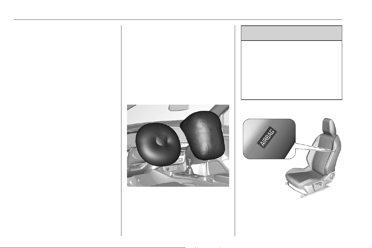
Front airbag system
The front airbag system consists of
one airbag in the steering wheel and
one in the instrument panel on the
front passenger side. These can be
identified by the word AIRBAG.
The front airbag system is triggered in
the event of a front-end impact of a
certain severity. The ignition must be
switched on.
The inflated airbags cushion the
impact, thereby reducing the risk of
injury to the upper body and head of
the front seat occupants
considerably.
9
Warning
Optimum protection is only
provided when the seat is in the
proper position.
Seat position 3 27.
Fasten the seat belt correctly and
engage securely. Only then is the
airbag able to protect.
Side airbag system
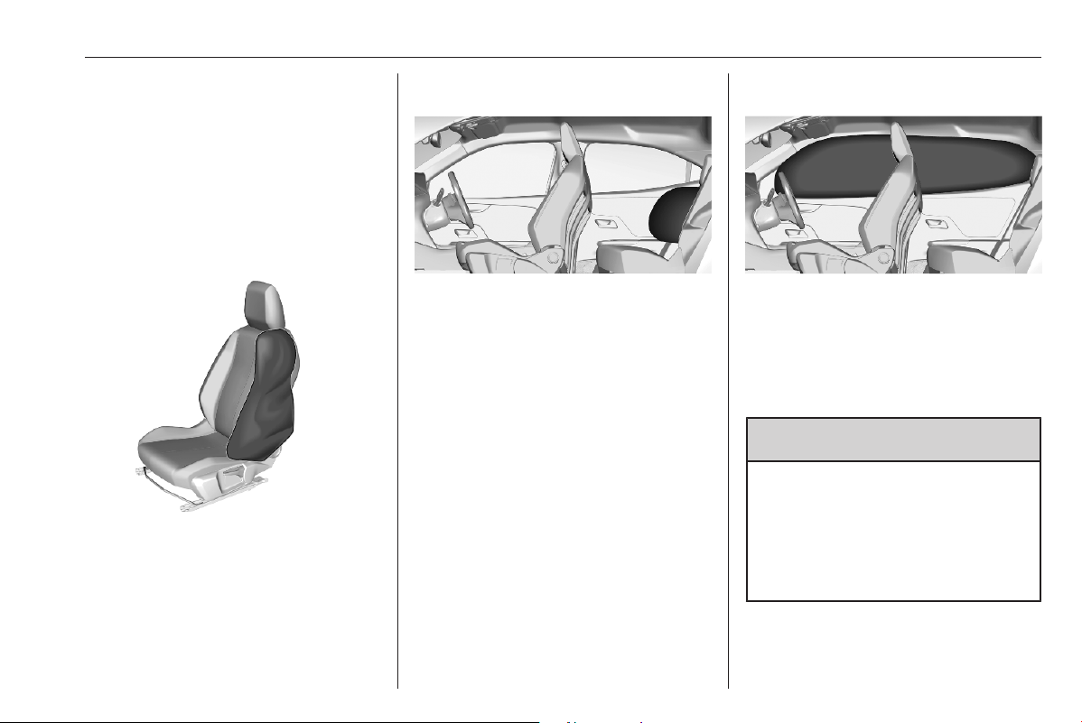
Seats, restraints 37
The side airbag system consists of an
airbag in each front seat backrest and
in the rear outer seat backrests. This
can be identified by the word
AIRBAG.
The side airbag system is triggered in
the event of a side impact of a certain
severity. The ignition must be
switched on.
The inflated airbags cushion the
impact, thereby reducing the risk of
injury to the upper body and pelvis in
the event of a side-on collision
considerably.
Notice
Only use protective seat covers that
have been approved for the vehicle.
Be careful not to cover the airbags.
Curtain airbag system
The curtain airbag system consists of
an airbag in the roof frame on each
side. This can be identified by the
word AIRBAG on the roof pillars.
The curtain airbag system is triggered
in the event of a side-on impact of a
certain severity. The ignition must be
switched on.
The inflated airbags cushion the
impact, thereby reducing the risk of
injury to the head in the event of a
side-on impact considerably.
9 Warning
The hooks on the handles in the
roof frame are only suitable for
hanging up light articles of
clothing, without coat hangers. Do
not keep any items in these
clothes.
38 Seats, restraints
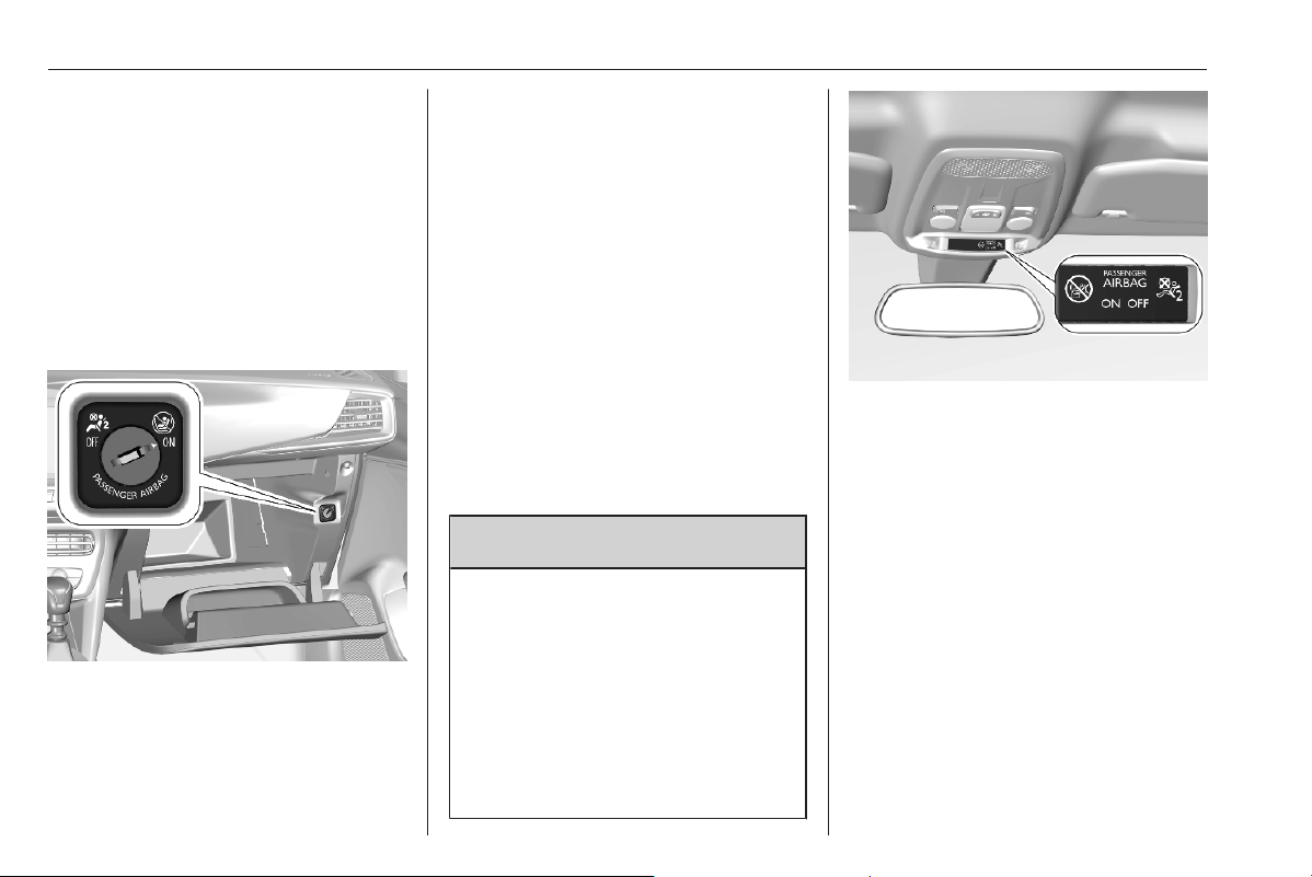
Airbag deactivation
The front passenger airbag system
must be deactivated for child restraint
system on the passenger seat
according to the instructions in the
table 3 43.
The side airbag and curtain airbag
systems, the belt pretensioners and
all driver airbag systems will remain
active.
The front passenger airbag system
can be deactivated via a key-
operated switch in the glovebox.
Use the ignition key to choose the
position:
OFF*
: front passenger airbag is
deactivated and will not
inflate in the event of a
collision, control indicator
OFF* illuminates
continuously in the centre
console.
ONÓ : front passenger airbag is
active.
Notice
After turning the key-operated
switch to position OFF *, keep on
turning towards this position until
key is removed.
9 Danger
Deactivate passenger airbag only
in combination with the use of a
child restraint system, subject to
the instructions and restrictions in
the table 3 43.
Otherwise, there is a risk of fatal
injury for a person occupying a
seat with a deactivated front
passenger airbag.
If the control indicator Ó illuminates
for approx. 60 seconds after the
ignition is switched on, the front
passenger airbag system will inflate
in the event of a collision.
If the control indicator * illuminates
after the ignition is switched on, the
front passenger airbag system is
deactivated. It stays on while the
airbag is deactivated.
If both control indicators are
illuminated at the same time, there is
a system failure. The status of the
system is not discernible, therefore
no person is allowed to occupy the
front passenger seat. Contact a
workshop immediately.

Seats, restraints 39
Consult a workshop immediately if
neither of the two control indicators
are illuminated.
Change status only when the vehicle
is stopped with the ignition off.
Status remains until the next change.
Control indicator for airbag
deactivation 3 70.
Child restraints
Child restraint systems
9 Danger
Make sure that children below
sufficient size and weight are
protected using a suitable child
restraint system. Never place a
child on the lap.
9 Danger
If using a rear-facing child restraint
system on the front passenger
seat, the airbag system for the
front passenger seat must be
deactivated. This also applies to
certain forward-facing child
restraint systems as indicated in
the tables 3 43.
Airbag deactivation 3 38.
Airbag label 3 33.
We recommend a child restraint
system which is tailored specifically to
the vehicle. For further information,
contact your workshop.
In case of any interference of the child
restraint system with vehicle seat
head restraint, adjust or remove the
corresponding head restraint 3 26.
When a child restraint system is being
used, pay attention to the following
usage and installation instructions
and also those supplied with the child
restraint system. The given
restrictions in the table refer to a test
body, which is the maximum
envelope of all existing child restraint
systems. Make sure that the front
seats do not interfere with the used
child restraint system.
Always comply with local or national
regulations. In some countries, the
use of child restraint systems is
forbidden on certain seats.
Only drive with the driver seat
correctly adjusted 3 27.
40 Seats, restraints
Child restraint systems can be
fastened with:
● Three-point seat belt
● ISOFIX brackets
● Top-tether
Three-point seat belt
Child restraint systems can be
fastened by using a three-point seat
belt. After fastening the child restraint
system the seat belt has to be
tightened.
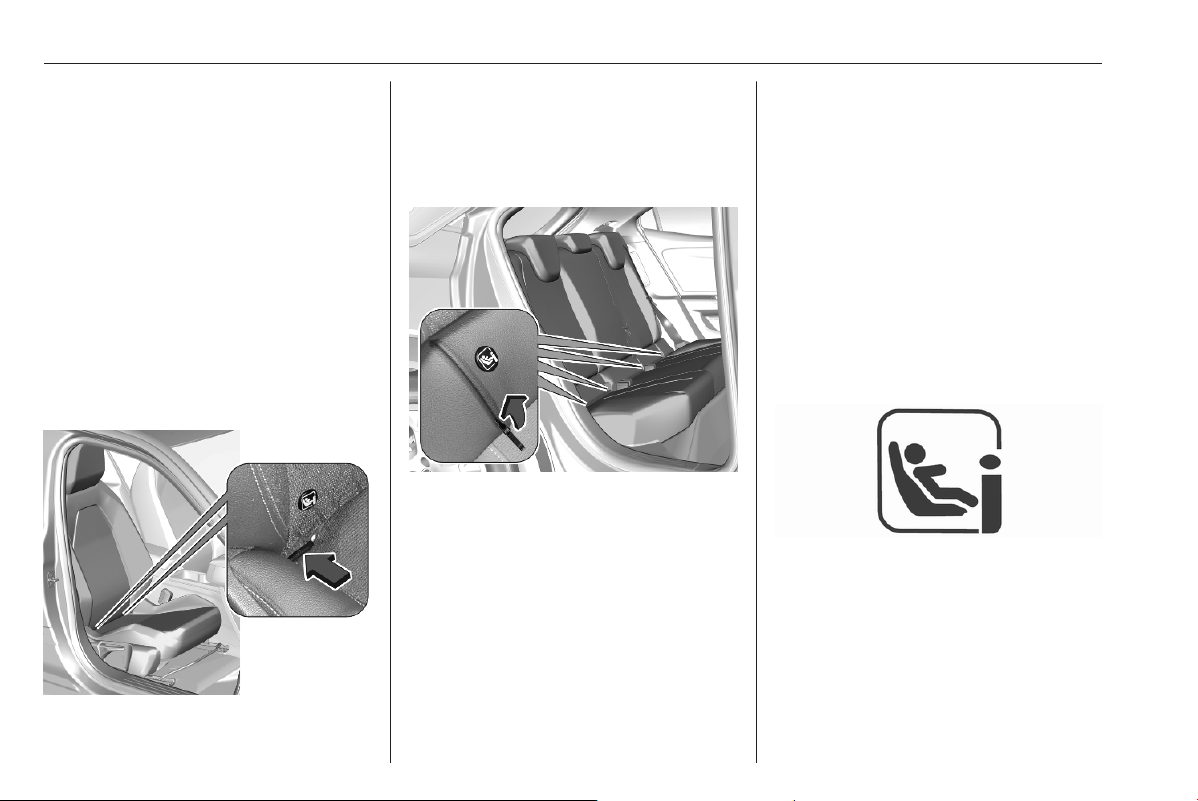
ISOFIX brackets
Fasten vehicle-approved ISOFIX
child restraint systems to the ISOFIX
brackets. Specific vehicle ISOFIX
child restraint system positions are
marked in the ISOFIX table 3 43.
ISOFIX brackets are indicated by a
label on the backrest. To get access
to the ISOFIX brackets, first pull the
zipper.
When fastening ISOFIX child restraint
systems on adjustable passenger
seats, such as the front passenger
seat, first incline the backrest as far as
necessary backwards in order to get
access to the ISOFIX brackets. After
the proper fastening of the ISOFIX
child restraint system, incline the
backrest forward again.
An i-Size child restraint system is an
universal ISOFIX child restraint
system according UN Regulation No.
129.
All i-Size child restraint systems can
be used on any vehicle seat suitable
for i-Size, i-Size table 3 43.
Either a Top-tether strap or a support
leg must be used in addition to the
ISOFIX brackets.
i-Size child seats and vehicle seats
with i-Size approval are marked with
i-Size symbol, see illustration.
Seats, restraints 41
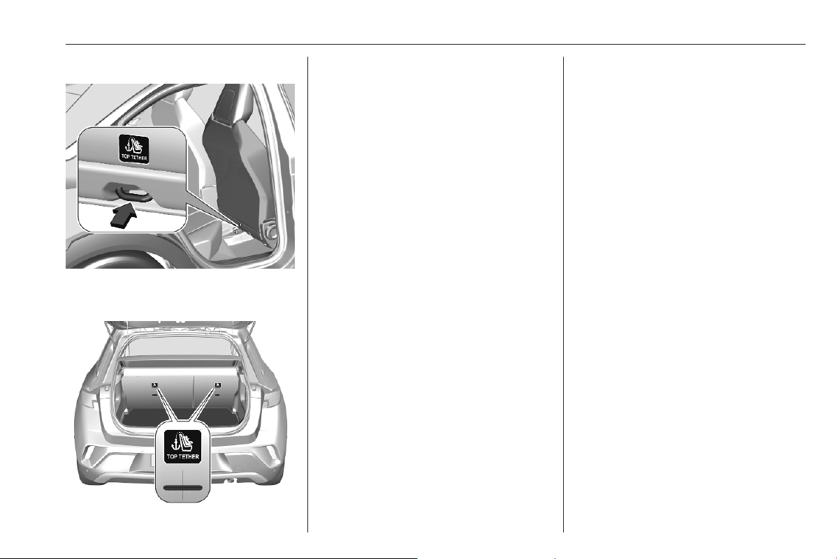
Top-tether anchors
Top-tether anchors are marked with
the symbol t for a child seat.
In addition to the ISOFIX brackets,
fasten the Top-tether strap to the
Top-tether anchors.
ISOFIX child restraint systems of
universal category positions are
marked in the table by IUF 3 43.
Selecting the right system
The rear seats are the most
convenient location to fasten a child
restraint system.
Children should travel facing
rearwards in the vehicle as long as
possible. This makes sure that the
child's backbone, which is still very
weak, is under less strain in the event
of an accident. Do not use forward
facing child restraint system at all
seats when child's weight is below 13
kg.
Suitable are child restraint systems
that comply with valid UN ECE
regulations. Check local laws and
regulations for mandatory use of child
restraint systems.
The following child restraints are
recommended for the following
weight classes:
● Group 0, Group 0+:
Maxi Cosi Cabriofix with or
without ISOFIX base for children
up to 13 kg
● Group I: Duo Plus with ISOFIX
and Top-tether for children from
9 kg to 18 kg
● Group II: Kidfix XP with or without
ISOFIX for children from 15 kg to
36 kg,
Kidfix 2R with or without ISOFIX
for children from 15 kg to 36 kg,
for Kidfix 2R ensure that vehicle
seat belt passes through secure
guard.
Graco Booster for children from
15 kg to 36 kg.
● Group III: Kidfix XP / Kidfix 2R
with or without ISOFIX for
children from 22 kg to 36 kg
Graco Booster for children from
22 kg to 36 kg
Ensure that the child restraint system
to be installed is compatible with the
vehicle type.

42 Seats, restraints
Child seat at the front: Adjust the front
passenger seat to the highest and
fully back longitudinal position with
the backrest straightened.
Child seat at the rear: Move the
vehicle's front seat forward and
straighten the backrest so that the
legs of the child in the "forward facing”
or the "rearward facing" child seat do
not touch the vehicle's front seat.
In case of any interference of Child
restraint system with vehicle seat
head rest, adjust or remove the
corresponding vehicle seat Head
rest.
Do not use forward facing child
restraints system when child's weight
is below 13 kg at all seats.
Please follow Child restraint
manufacturers instructions to install
corresponding child restraints in
vehicle.
For semi-universal or vehicle specific
child restraint system (ISOFIX or
belted child restraint system), see the
vehicle list provided in the user
manual of the child restraint system.
Ensure that the mounting location of
the child restraint system within the
vehicle is correct, see following table.
Allow children to enter and exit the
vehicle only on the side facing away
from the traffic.
When the child restraint system is not
in use, secure the seat with a seat belt
or remove it from the vehicle.
Notice
Do not affix anything on the child
restraint systems and do not cover
them with any other materials.
A child restraint system which has
been subjected to stress in an
accident must be replaced.

Seats, restraints 43
Child restraint installation locations
Installation of universal, ISOFIX and i-Size child seats
As required by European regulations, this table gives the options for installing child seats secured using the seat belt and
universally approved as well as the larger ISOFIX and i-Size child seats on seat positions equipped with ISOFIX mountings
in the vehicle.
Yes : Suitable for fitment of the designated catecory of the child restraint system.
No : Not suitable for fitment of the designated catecory of the child restraint system.
Child restraint system categories
Front passenger seat
with activated airbag
ON
Front passenger seat
with deactivated airbag
OFF
Rear outer
seats
Rear centre
seat
1)
Universal belted child restraint
system
2)
Yes
3)
4)
5)
Yes
4)
6)
7)
Yes NO
i-size child restraint system
Yes
3)
8)
Yes
6)
8)
Yes –
Position equipped with a Top-tether
fixing
Yes
3)
8)
Yes
6)
8)
Yes –
Carry-cot (ISOFIX lateral facing child
restraint system)
ISOFIX child restraint fixture: L1, L2
NO NO NO –
ISOFIX rearward facing child restraint
system
ISOFIX child restraint fixture: R1, R2
NO
Yes
8)
9)
12)
Yes
10)
11)
12)
–

44 Seats, restraints
Child restraint system categories
Front passenger seat
with activated airbag
ON
Front passenger seat
with deactivated airbag
OFF
Rear outer
seats
Rear centre
seat
1)
ISOFIX forward facing child restraint
system
ISOFIX child restraint fixture: F2, F2X,
F3
Yes
8)
12)
NO
Yes
12)
–
ISOFIX rearward facing child restraint
system
ISOFIX child restraint fixture: R3
NO NO
Yes
10)
11)
12)
–
Booster seat - reduced width: B2 Yes NO Yes NO
Booster seat - full width: B3 Yes NO Yes NO
1)
Child restraint system installation is not allowed on rear centre seat.
2)
Universal child seat: chiId seat that can be installed in all vehicles using the seat belt. Applies to all stature and mass groups.
3)
Only forward facing child restraint system
4)
For a seat with height adjustment, set it to the highest and fully back longitudinal position.
5)
Only a forward facing child restraint system is authorised at this seat position with the front passenger's airbag activated ON.
6)
Only rearward facing child restraint system
7)
To install a rearward facing child restraint system at this seat position, the front passenger's airbag must be deactivated OFF.
8)
Seats fitted with ISOFIX / i-Size compliant mountings.
9)
The vehicle seat must be adjusted in the rearmost longitudinal position.
10)
Adjust the driver seat ahead of the child restraint system to the longitudinal middle and maximum height position. If necessary, adjust
the driver's seat backrest angle. Ensure that inclination angle of the backrest does not exceed the corresponding torso angle of 15°.
11)
Move the passenger seat ahead of the child restraint system forwards as far as necessary.
12)
In case of any interference of Child restraint system with vehicle seat head rest, adjust or remove the corresponding vehicle seat
head rest.

Seats, restraints 45
Size of child restraint fixture (1, 2, 3):
● R1 means rearward facing child restraint fixture for mass group 0 up to 10 kg and mass group 0+ up to 13 kg, age
around 0-1 year.
● R2 means reduced size of rearward facing child restraint fixture for mass group 0+ up to 13 kg and mass group 1
from 9 to 18 kg, age around 2-4 years.
● R3 means full size of rearward facing child restraint fixture for mass group 0+ up to 13 kg and mass group 1 from 9
to 18 kg, age around 2-4 years.
● F2, F2X mean reduced height of forward facing child restraint fixture for mass group 1 from 9 to 18 kg, age around
6-7 years.
● F3 means full height of forward facing child restraint fixture for mass group 1 from 9 to 18 kg, age around 7-10 years.
46 Storage
Storage
Storage compartments ................ 46
Glovebox ................................... 46
Cupholders ................................ 46
Door panel storage .................... 47
Centre console storage ............. 47
Load compartment ....................... 48
Load compartment cover ........... 49
Rear floor storage cover ............ 49
Lashing eyes ............................. 50
Warning triangle ........................ 50
Roof rack system ......................... 51
Roof rack ................................... 51
Loading information ..................... 51
Storage compartments
9 Warning
Do not store heavy or sharp
objects in the storage
compartments.
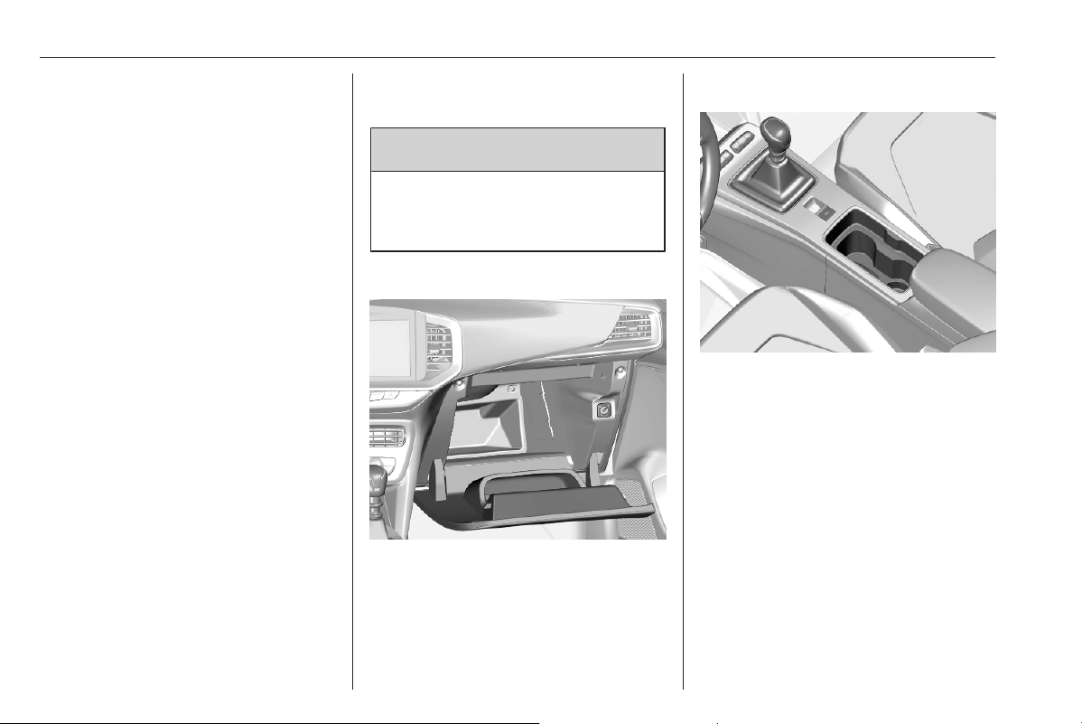
Glovebox
Pull lever to open the glovebox.
The glovebox should be closed whilst
driving.
Cupholders
Cupholders are located in the centre
console.
Storage 47
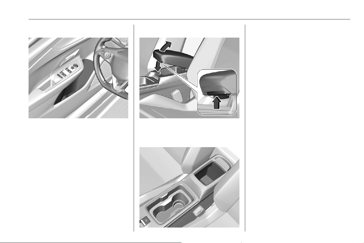
Door panel storage
A storage compartment is located in
the front and rear door panels.
Centre console storage
Slide armrest backwards, push button
and fold upwards. Under the armrest
there is a storage compartment.
A storage compartment is located in
the centre console.
48 Storage
Load compartment
The rear seat backrest is divided into
2/3 to 1/3 parts. Both parts can be
folded down individually to increase
the size of the load compartment.
Before folding rear seat backrests,
execute the following if necessary:
● Move front seats forward if
necessary.
● Remove the load compartment
cover 3 49.
● Press and hold the catch to push
the head restraints down 3 26.
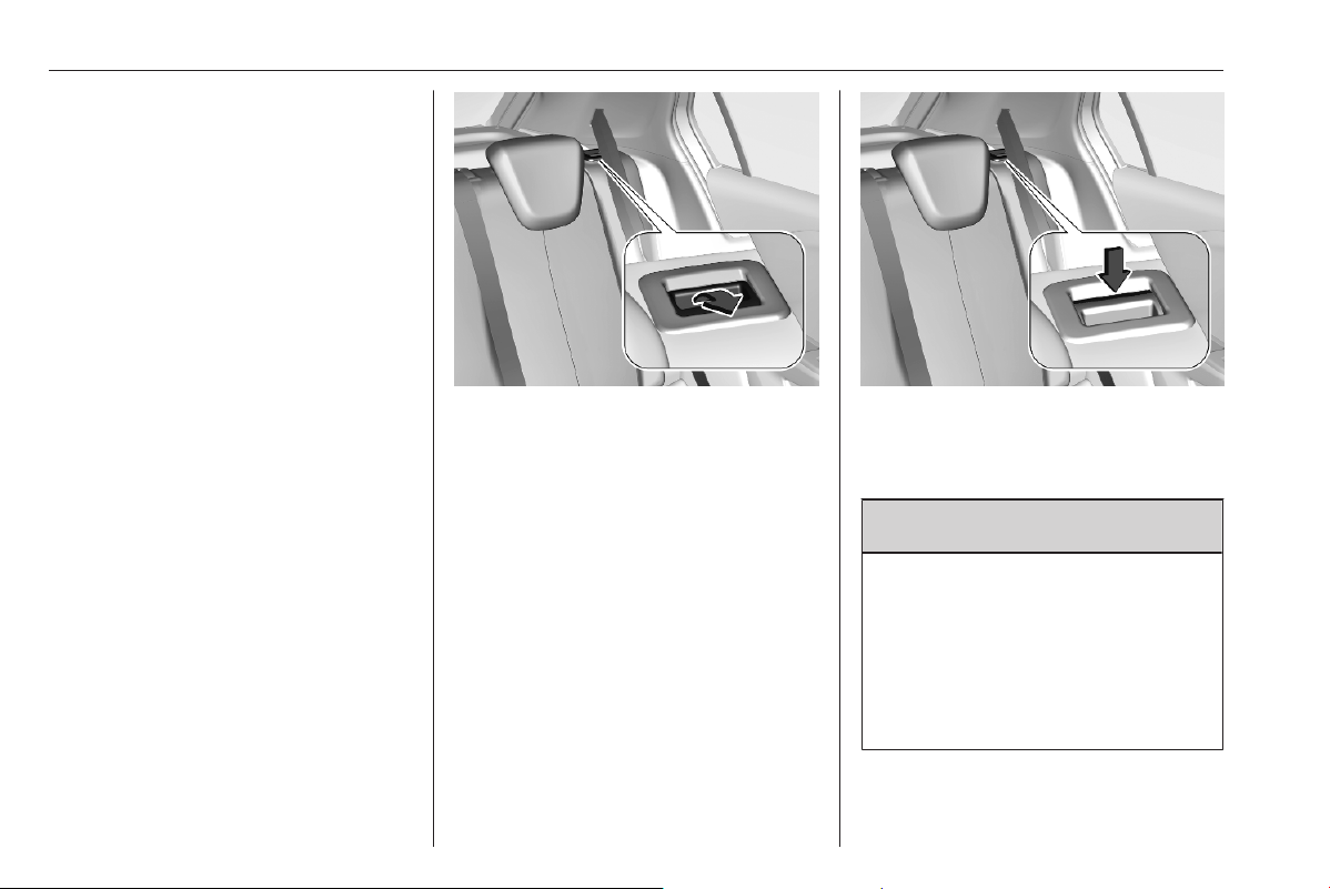
Folding down/up rear backrests
● Check that the seat belts are not
engaged in the seat belt buckles,
so that the backrests can be
moved.
● Pull the release lever on one or
both outer sides and fold down
the backrests onto the seat
cushion.
● To fold up, raise the backrests
and guide them into an upright
position until they engage
audibly. Make sure that the belts
are positioned correctly and stay
clear of the folding area.
The backrests are properly
engaged when the red marks
near the release levers are no
longer visible.
9 Warning
When folding up, ensure that
backrests are securely locked in
position before driving. Failure to
do so may result in personal injury
or damage to the load or vehicle in
the event of hard braking or a
collision.
Storage 49
The seat belt of the centre seat could
be blocked when the backrest is
folded up too quickly. To unlock the
retractor, push in the seat belt or pull
it out by approx. 20 mm then release.
Load compartment cover
Do not place any objects on the cover.
Removing cover
Unhook retaining straps from tailgate.
Lift cover at the front and push it
upwards at the rear.
Remove the cover.
Fitting cover
Engage cover in side guides and fold
downwards. Attach the retaining
straps to the tailgate.
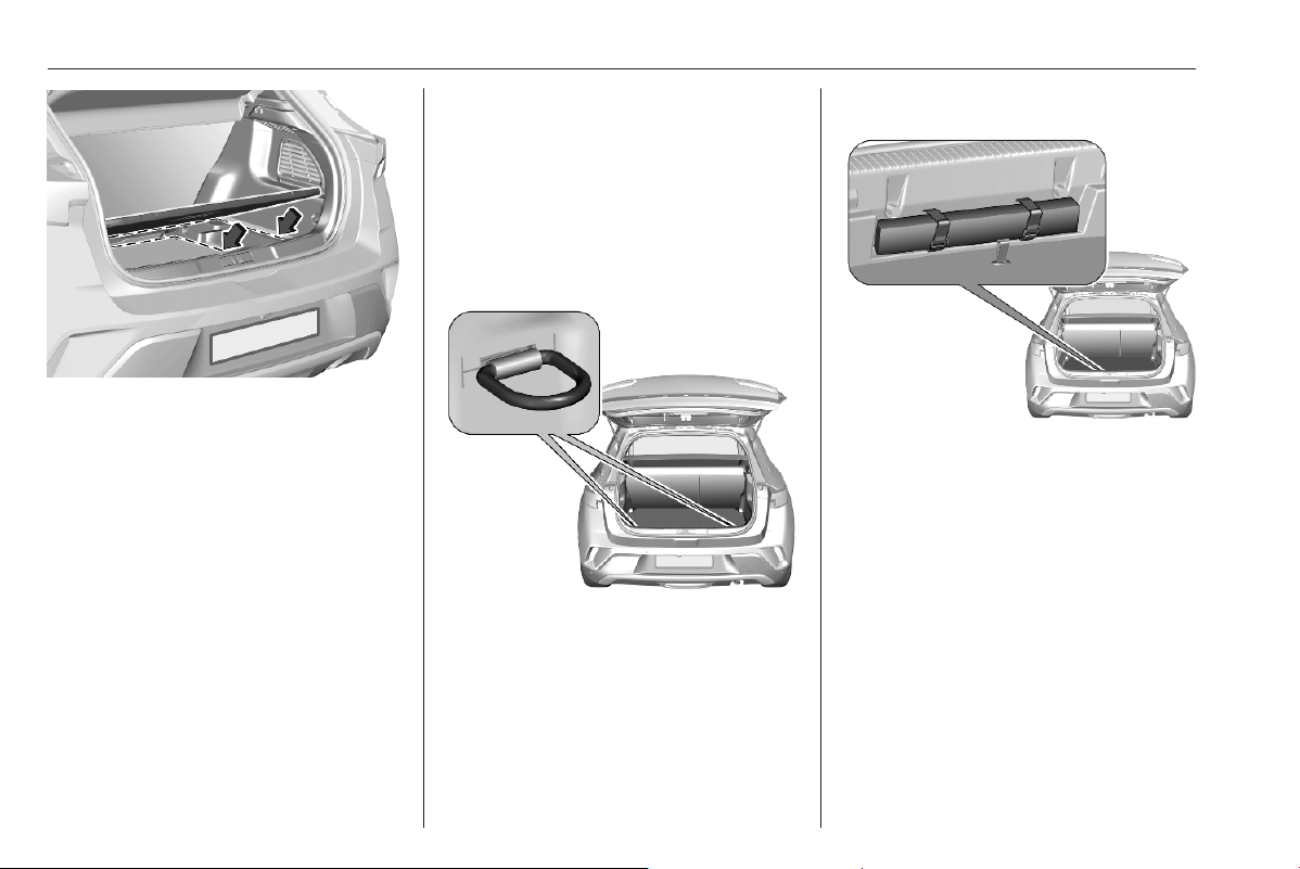
Rear floor storage cover
The rear floor cover can be lifted and
removed. Use opening to raise the
rear floor cover and then remove it.
Double load floor
The double load floor can be inserted
in the load compartment in two
positions:
50 Storage
● lower position above the rear
floor storage cover
● upper position interlocked into
back panel trim
To remove, use opening to raise the
rear floor cover and lift it up.
If mounted in the upper position, the
space between the load floor and the
spare wheel well cover can be used
as a storage compartment.
In this position, if the rear seat
backrests are folded forwards, an
almost completely flat load bay is
created.
In the upper position, the double load
floor is able to withstand an equally
distributed maximum load of 60 kg. In
the lower position, the double load
floor is able to withstand the
maximum permissible load.
Lashing eyes
The lashing eyes are designed to
secure items against slippage, e.g.
using lashing straps or luggage net.
Warning triangle
Stow the warning triangle in the space
at the rear of the load compartment
and secure it with the Velcro
®
fastener.
Storage 51
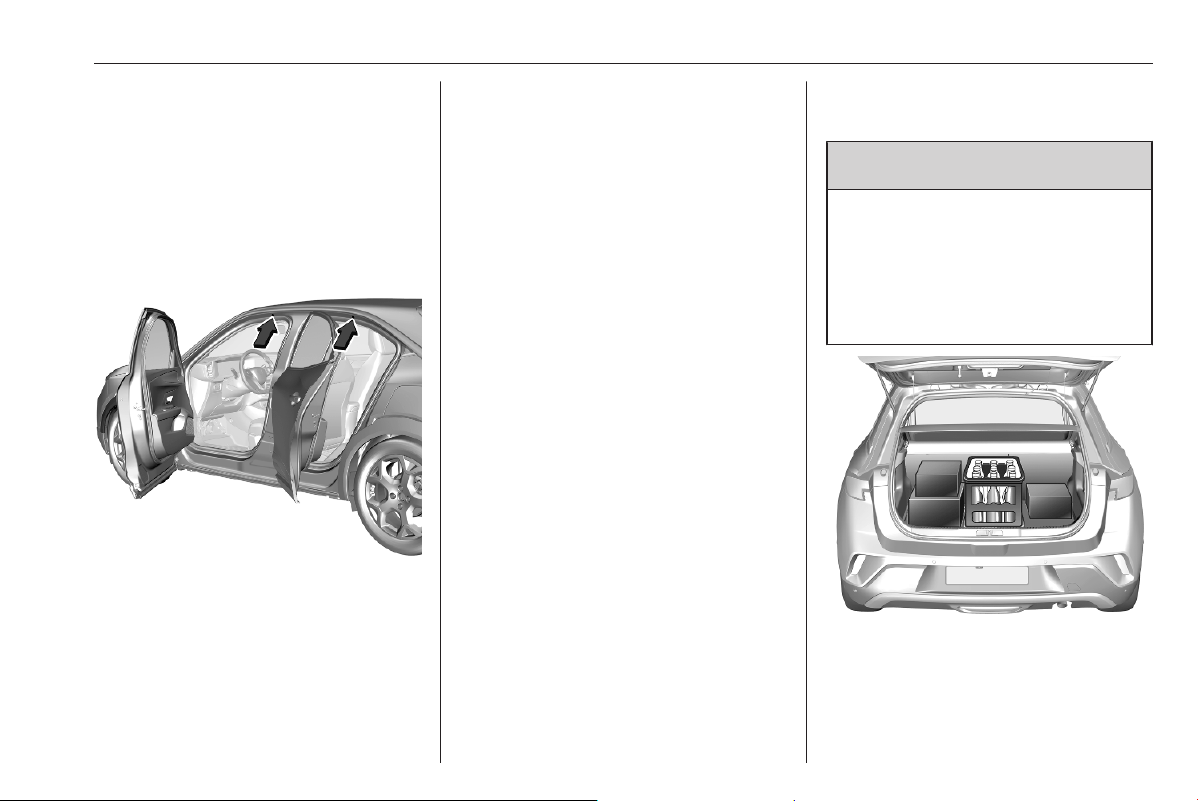
Roof rack system
Roof rack
For safety reasons and to avoid
damage to the roof, the vehicle
approved roof rack system is
recommended. For further
information, contact your workshop.
Open all doors.
Mounting points are located in each
door frame of the vehicle body.
Fasten the roof rack according to the
installation instructions delivered with
the roof rack.
Remove the roof rack when not in
use.
Loading information
9 Warning
Always make sure that the load in
the vehicle is securely stowed.
Otherwise objects can be thrown
around inside the vehicle and
cause personal injury or damage
to the load or car.
● Heavy objects in the load
compartment should be placed
against the seat backrests. Make
sure that the backrests are

52 Storage
securely engaged. If objects can
be stacked, heavier objects
should be placed at the bottom.
● Prevent sliding of loose objects
by securing them with straps
attached to the lashing eyes
3 50.
● Do not allow the load to protrude
above the upper edge of the
backrests.
● Do not place any objects on the
load compartment cover or the
instrument panel, and do not
cover the sensor on top of the
instrument panel.
● The load must not obstruct the
operation of the pedals, parking
brake and gear selector, or
hinder the freedom of movement
of the driver. Do not place any
unsecured objects in the interior.
● Do not drive with an open load
compartment.
● The payload is the difference
between the permitted gross
vehicle weight (see identification
plate 3 285) and the EC kerb
weight.
To calculate the payload, enter
the data for your vehicle in the
weights table at the front of this
manual.
The EC kerb weight includes
weights for the driver (68 kg),
luggage (7 kg) and all fluids (fuel
tank 90% full).
Optional equipment and
accessories increase the kerb
weight.
● Driving with a roof load increases
the sensitivity of the vehicle to
cross-winds and has a
detrimental effect on vehicle
handling due to the vehicle's
higher centre of gravity.
Distribute the load evenly and
secure it properly with retaining
straps. Adjust the tyre pressure
and vehicle speed according to
the load conditions. Check and
retighten the straps frequently.
Do not drive faster than 75 mph.
The permissible roof load is
75 kg. The roof load is the
combined weight of the roof rack
and the load.

Instruments and controls 53
Instruments and
controls
Instrument panel overview ........... 55
Controls ....................................... 57
Steering wheel adjustment ........ 57
Steering wheel controls ............. 57
Heated steering wheel ............... 57
Horn ........................................... 58
Pedestrian safety alert ............... 58
Windscreen wiper and washer ..58
Rear window wiper and
washer ...................................... 60
Outside temperature .................. 60
Clock ......................................... 61
Power outlets ............................. 61
Inductive charging ..................... 62
Warning lights, gauges and indi‐
cators ........................................... 63
Speedometer ............................. 63
Odometer .................................. 63
Tachometer ............................... 64
Fuel gauge ................................ 64
High voltage battery gauge ....... 65
Power indicator gauge ............... 65
Total vehicle range .................... 66
Engine coolant temperature
gauge ....................................... 66
Engine oil level monitor ............. 66
Service display .......................... 66
Control indicators ...................... 67
Turn lights .................................. 69
Seat belt reminder ..................... 69
Airbag and belt tensioners ......... 70
Airbag deactivation .................... 70
Charging system ....................... 70
Malfunction indicator light .......... 70
Service vehicle soon ................. 71
Stop engine ............................... 71
System check ............................ 71
Brake and clutch system ........... 71
Parking brake ............................ 71
Electric parking brake fault ........ 72
Automatic operation of electric
parking brake off ....................... 72
Antilock brake system (ABS) ..... 72
Gear shifting .............................. 72
Lane keep assist ....................... 72
Advanced lane keep assist ........ 73
Parking assist ............................ 73
Electronic Stability Control and
Traction Control system ........... 73
Engine coolant temperature ...... 73
Preheating ................................. 73
Exhaust filter .............................. 73
AdBlue ....................................... 74
Deflation detection system ........ 74
Engine oil pressure .................... 74
Low fuel ..................................... 75
Charging cable connected ......... 75
Vehicle ready ............................. 75
Reduced engine power ............. 75
High voltage battery
temperature high ...................... 75
Autostop .................................... 75
Exterior light .............................. 75
Low beam .................................. 75
High beam ................................. 76
High beam assist ....................... 76
LED headlights .......................... 76
Front fog lights ........................... 76
Rear fog light ............................. 76
Rain sensor ............................... 76
Pedestrian safety alert fault ....... 76
Active emergency braking ......... 76
Traffic sign assistant .................. 76
Door open .................................. 77
Displays ....................................... 77
Driver Information Centre .......... 77
Info Display ................................ 78
Vehicle messages ........................ 80
Warning chimes ......................... 80
Vehicle personalisation ................ 81


Instruments and controls 55
Instrument panel overview

56 Instruments and controls
1 Power windows ..................... 23
2 Exterior mirrors ..................... 20
3 Side air vents ...................... 159
4 Turn lights, headlight
flash, low / high beam ........... 89
Parking lights ........................ 90
Buttons for Driver
Information Centre ................ 77
5 Cruise control ..................... 188
Speed limiter ....................... 190
Adaptive cruise control ....... 192
Heated steering wheel .......... 57
6 Instruments ........................... 63
Driver Information Centre ...... 77
7 Infotainment controls
8 Windscreen wiper and
washer, rear wiper and
washer ................................. 58
9 Power button ....................... 164
10 Central locking system ......... 10
11 Controls for Info Display
operation .............................. 78
12 Hazard warning flashers ...... 88
13 Centre air vents .................. 159
14 Vauxhall Connect ................. 82
15 Reading lights ...................... 91
16 Interior lights ........................ 91
17 Seat belt reminder ................ 30
Airbag deactivation .............. 38
18 Interior mirror ....................... 21
19 Glovebox .............................. 46
20 Centre air vents .................. 159
21 Climate control system ........ 154
22 USB port .............................. 61
23 Power outlet .......................... 61
24 Parking assist ..................... 205
Lane departure warning ..... 223
Lane keep assist ................ 224
Advanced lane keep assist 226
Stop start system ............... 167
25 Selector lever ...................... 180
26 Parking brake ..................... 183
27 Ignition switch ..................... 164
28 Steering wheel adjustment ..57
29 Horn ..................................... 58
30 Fuse box ............................ 260
31 Bonnet release lever .......... 251
32 Light switch .......................... 84
Headlight range
adjustment ........................... 86
Front fog lights ...................... 89
Rear fog light ........................ 90
Instrument panel
illumination ............................ 91
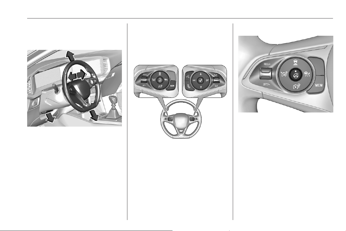
Instruments and controls 57
Controls
Steering wheel adjustment
Unlock lever, adjust steering wheel,
then engage lever and ensure it is
fully locked.
Do not adjust steering wheel unless
vehicle is stationary and, depending
on version, the steering wheel lock
has been released.
Steering wheel controls
Some driver assistance systems,
Infotainment system and a connected
mobile phone can be operated via the
controls on the steering wheel.
Further information is available in the
respective infotainment system
section 3 93.
Cruise control 3 188.
Speed limiter 3 190.
Adaptive cruise control 3 192.
Heated steering wheel
Activate heating by pressing Z.
Activation is indicated by the LED in
the button.
The heating works only when the
outside temperature is below 20 °C.
Stop-start system 3 167.
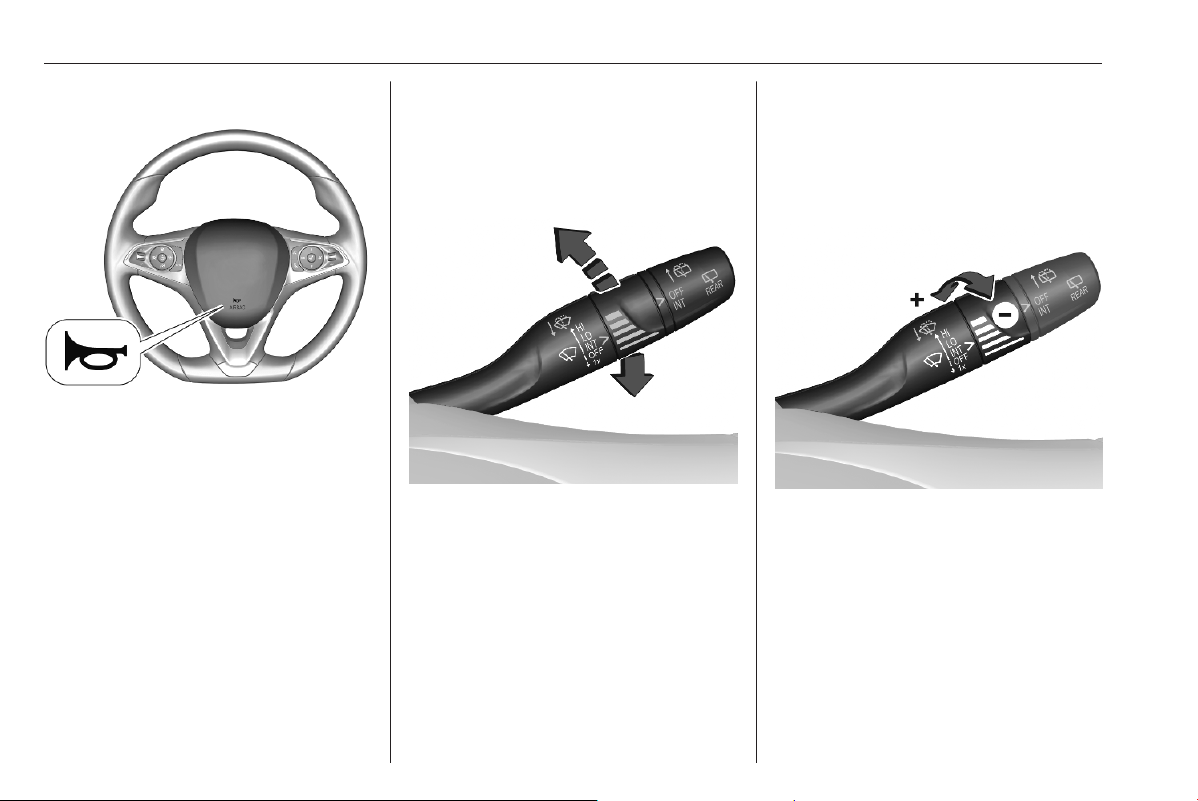
58 Instruments and controls
Horn
Press d.
Pedestrian safety alert
The sound of the pedestrian safety
alert is generated to indicate the
vehicle presence to pedestrians. It is
active up to 19 mph.
Windscreen wiper and
washer
Windscreen wiper with adjustable
wiper frequency
HI : fast
LO : slow
INT : interval wiping
OFF : off
1x : single wipe
Do not use if the windscreen is frozen.
Switch off in car washes.
To activate interval wiping mode the
next time ignition is switched on,
press the lever downwards to position
OFF and back to INT.
Adjustable wiper frequency
Wiper lever in position INT.
Turn the adjuster wheel to adjust the
desired wipe freqeuency.
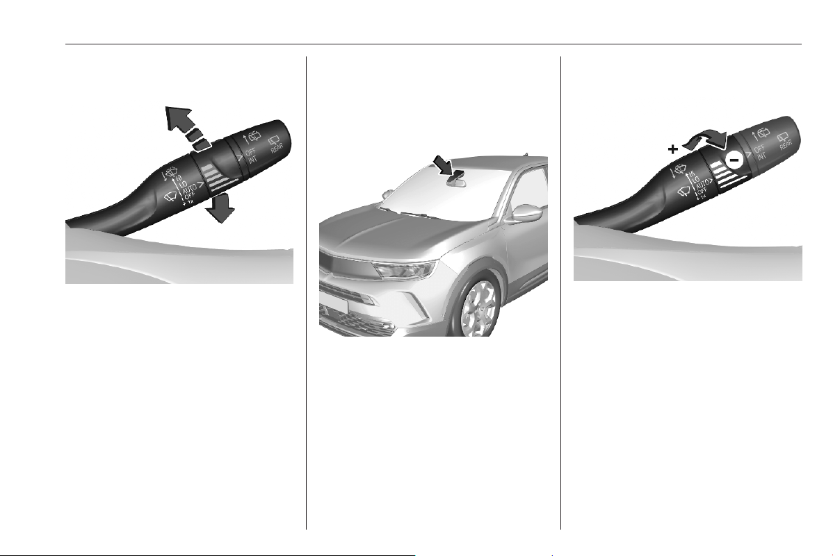
Instruments and controls 59
Windscreen wiper with rain
sensor
HI : fast
LO : slow
AUTO : automatic wiping with rain
sensor
OFF : off
1x : single wipe
In AUTO position, the rain sensor
detects the amount of water on the
windscreen and automatically
regulates the frequency of the
windscreen wiper. y illuminates in
the Driver Information Centre.
For a single wipe when the
windscreen wiper is off, press the
lever downwards to position 1x.
Do not use if the windscreen is frozen.
Switch off in car washes.
Keep the sensor free from dust, dirt
and ice.
Adjustable sensitivity of the rain
sensor
Turn the adjuster wheel to adjust the
sensitivity.
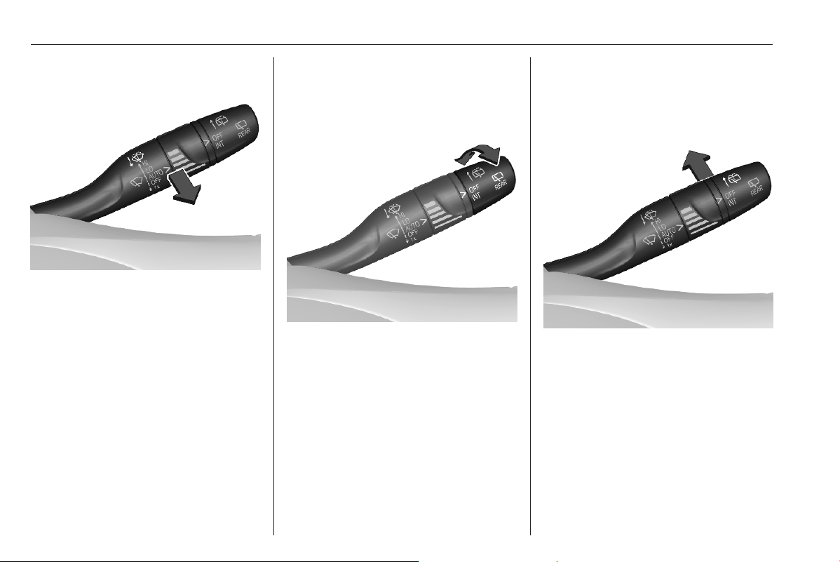
60 Instruments and controls
Windscreen washer
Pull lever. Washer fluid is sprayed
onto the windscreen and the wiper
wipes a few times.
Washer fluid 3 254.
Rear window wiper and
washer
Rear window wiper
OFF : off
INT : intermittent operation
Do not use if the rear window is
frozen.
Switch off in car washes.
The rear window wiper comes on
automatically when the windscreen
wiper is switched on and reverse gear
is engaged.
Activation or deactivation of this
function can be changed in the
Vehicle personalisation menu 3 81.
Rear window washer
Push lever.
Washer fluid is sprayed onto the rear
window and the wiper wipes a few
times.
Washer fluid 3 254.
Outside temperature
A drop in temperature is indicated
immediately and a rise in temperature
after a time delay.
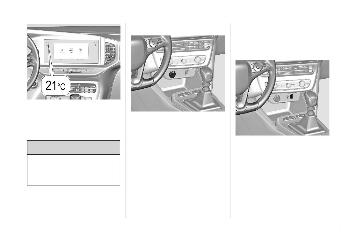
Instruments and controls 61
Illustration shows an example.
If outside temperature drops to a
certain temperature, a warning
message is displayed in the Driver
Information Centre.
9 Warning
The road surface may already be
icy even though the display
indicates a few degrees above 0
°C.
Clock
Date and time are shown in the Info
Display.
Power outlets
Do not exceed the maximum power
consumption of 120 W.
The 12 V power outlet is deactivated
in the event of low vehicle battery
voltage.
Electrical accessories that are
connected must comply with the
electromagnetic compatibility
requirements laid down in
DIN VDE 40 839.
Do not connect any current-delivering
accessories, e.g. electrical charging
devices or batteries.
Do not damage the outlet by using
unsuitable plugs.
Stop-start system 3 167.
USB ports
The USB port provides 5 V.
Notice
The sockets must always be kept
clean and dry.
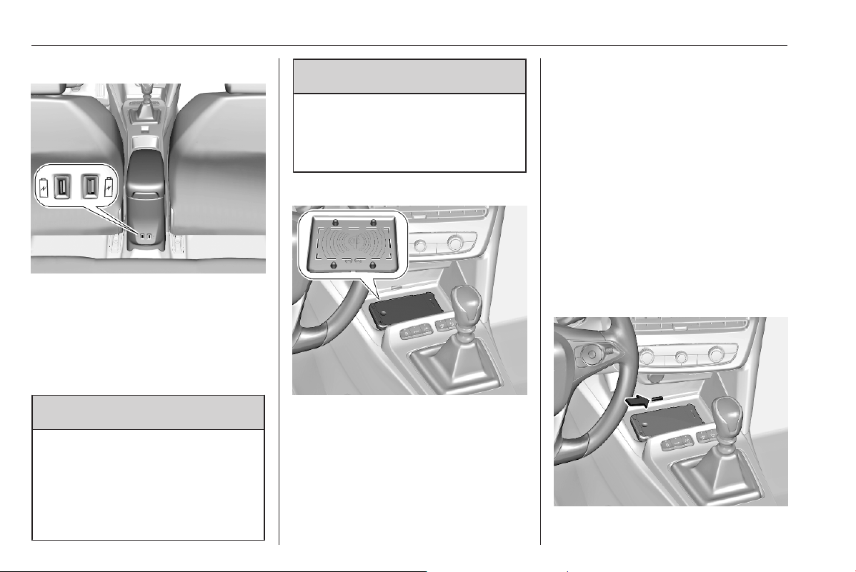
62 Instruments and controls
Rear USB ports
The slot below the USB ports on the
rear side of the storage container is
intented to attach an accessory
cupholder.
Inductive charging
9 Warning
Inductive charging can affect the
operation of implanted
pacemakers or other medical
devices. If applicable, seek
medical advice before using the
inductive charging device.
9
Warning
Remove any metal objects from
the charging device before
charging a mobile device, as these
objects could become very hot.
To charge a mobile device:
1. Remove all objects from the
charging device.
2. Place the mobile device with the
display facing upwards on the
charging area. Note that the
mobile device must be placed
between the positioning aids.
Qi compatible mobile devices can be
charged inductively.
On some mobile devices, a back
cover with an integrated coil or a
jacket may be required to use
inductive charging.
Protective cover for the mobile device
could have impact on the inductive
charging.
In the event that the mobile device is
not charging properly, rotate it 180°
and place it on the charging device
again.
Status LED
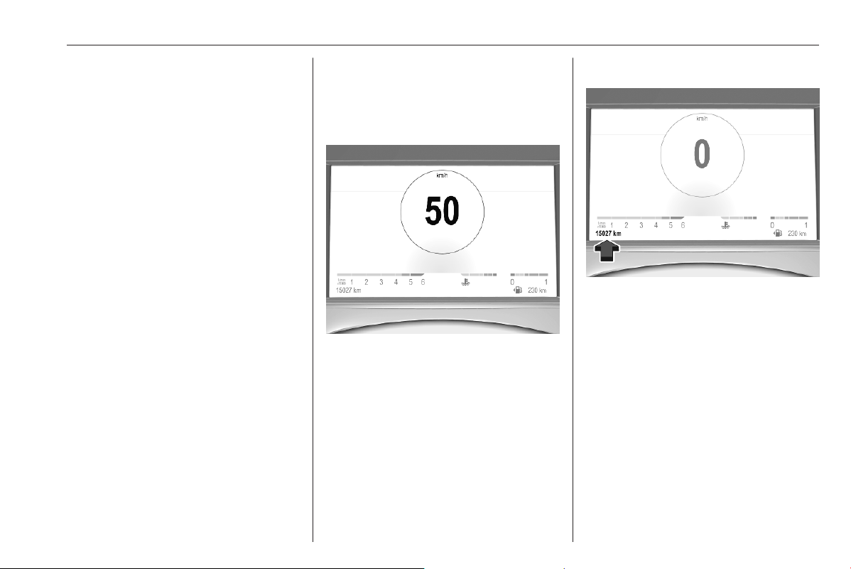
Instruments and controls 63
The LED indicates the current
charging status.
Illuminates green
The mobile device is charging.
Flashes yellow
The mobile device has not been
centred properly in the charging zone
or an unknown object has been
detected in the charging zone.
Illuminates yellow
There is a problem with the mobile
device's battery or a fault of the
inductive charger has been detected.
If the problem persists, seek the
assistance of a workshop.
Warning lights, gauges
and indicators
Speedometer
Indicates vehicle speed.
Odometer
The total recorded distance is
displayed in miles.
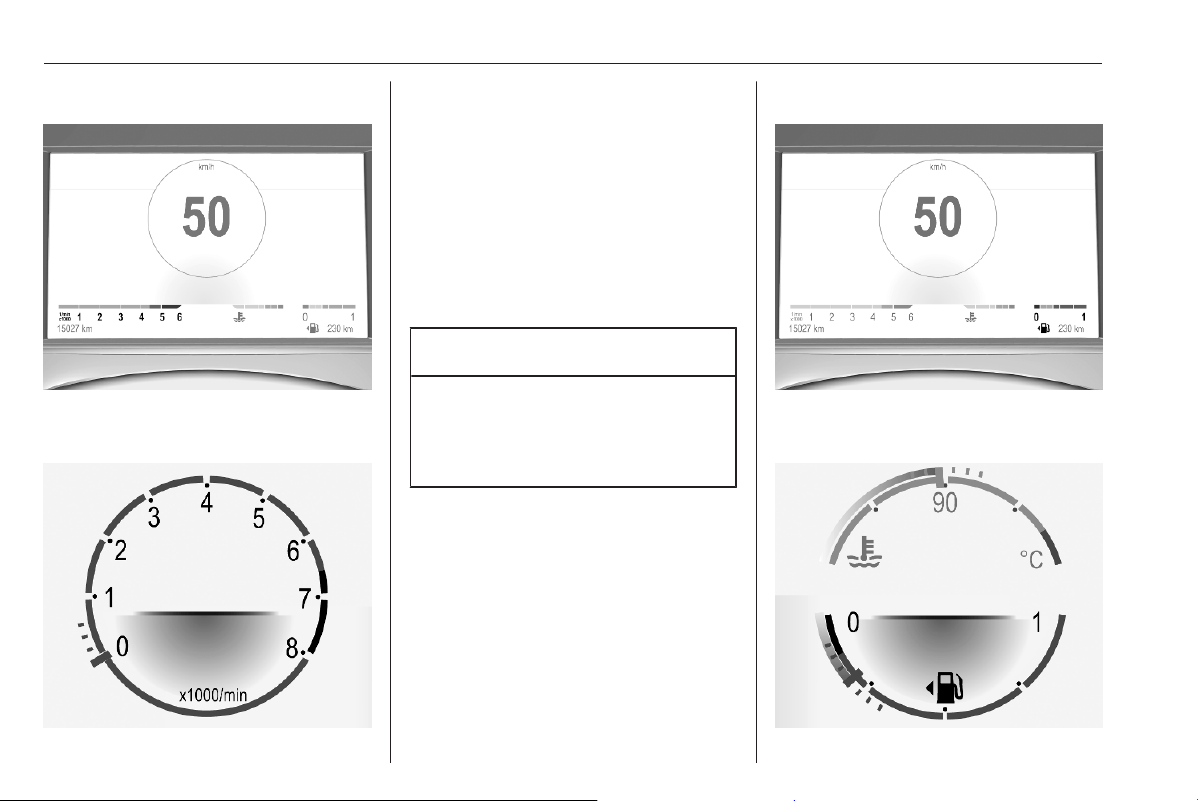
64 Instruments and controls
Tachometer
Depending on version, two variants
are available.
Displays the engine speed.
Drive in a low engine speed range for
each gear as much as possible.
A red marker indicates the beginning
of the warning zone of excessive
revolutions. For Diesel engines, the
warning zone starts at 5000
revolutions per minute. For petrol
engines, the warning zone starts at
6500 revolutions per minute.
Caution
If the indicator is in the red warning
zone, the maximum permitted
engine speed is exceeded. The
engine can be damaged.
Fuel gauge
Depending on version, two variants
are available.
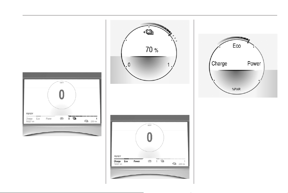
Instruments and controls 65
Control indicator r illuminates yellow
if the fuel level is low.
Never run the fuel tank dry.
The top-up quantity may be less than
the specified fuel tank capacity, due
to the remaining fuel in the tank.
High voltage battery gauge
Depending on version, two variants
are available.
Displays the high voltage battery
state of charge.
Power indicator gauge
Depending on version, two variants
are available.
The power indicator gauge informs
about the current energy situation of
the vehicle.
Charge : Battery is being charged
with energy resulting from
braking or deceleration of
the vehicle
Eco : An optimum in energy is
accessible in all driving
modes
Power : Vehicle is driven in a
dynamic driving style with
focus on performance
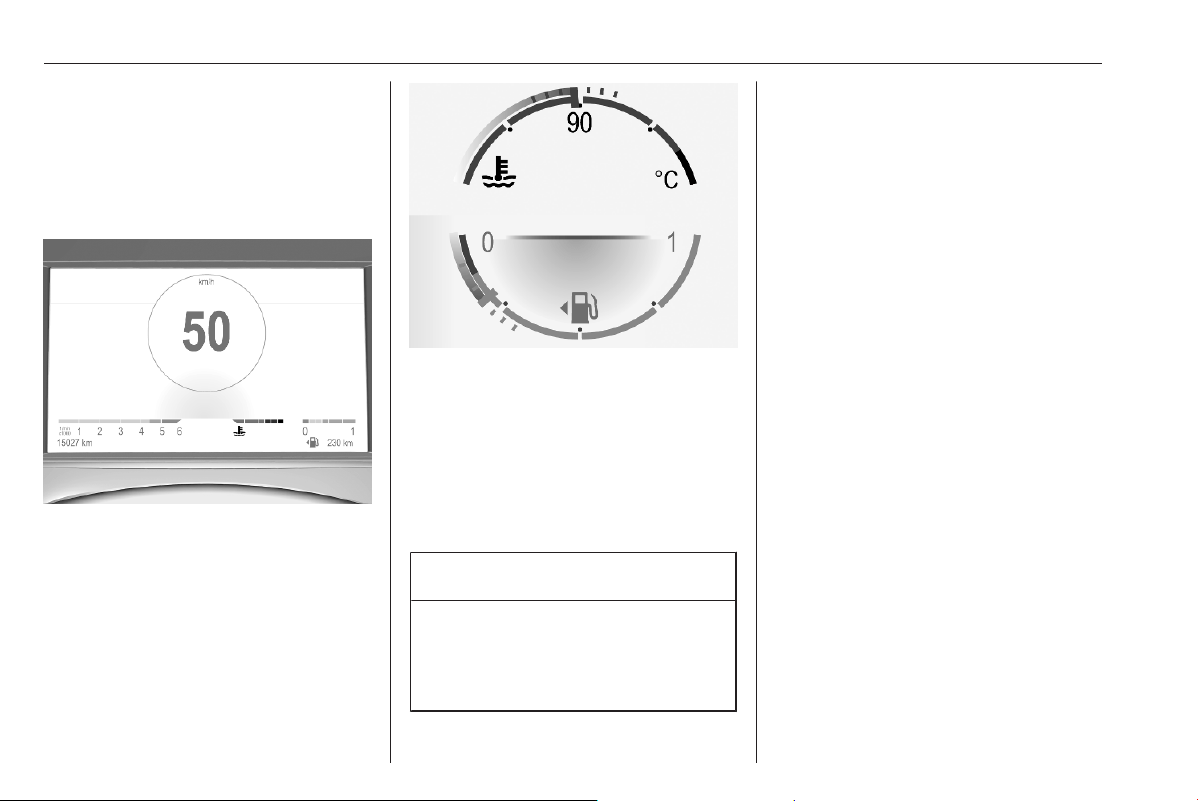
66 Instruments and controls
Total vehicle range
Displays the total vehicle range.
Engine coolant temperature
gauge
Depending on version, two variants
are available.
Displays the coolant temperature.
grey marking /
90
: normal operating
temperature
red marking : temperature too
high
Control indicator V illuminates red if
coolant temperature is too high.
Caution
If engine coolant temperature is
too high, stop vehicle, switch off
engine. Danger to engine. Check
coolant level.
Engine oil level monitor
The state of the engine oil level is
displayed in the Driver Information
Centre for a few seconds following
the service information after switching
on the ignition.
A proper state of engine oil level is
indicated by a message.
If engine oil level is low, T flashes
and a message is indicated,
accompanied by the C indicator.
Confirm engine oil level by using the
dipstick and top up engine oil
respectively.
Engine oil 3 251.
A fault of measurement is indicated
by a message. Check engine oil level
manually by using the dipstick.
Service display
The service system informs when to
change the engine oil and filter or a
vehicle service is required. Based on
driving conditions, the interval at
which an engine oil and filter change
are required can vary considerably.
Service information 3 280.
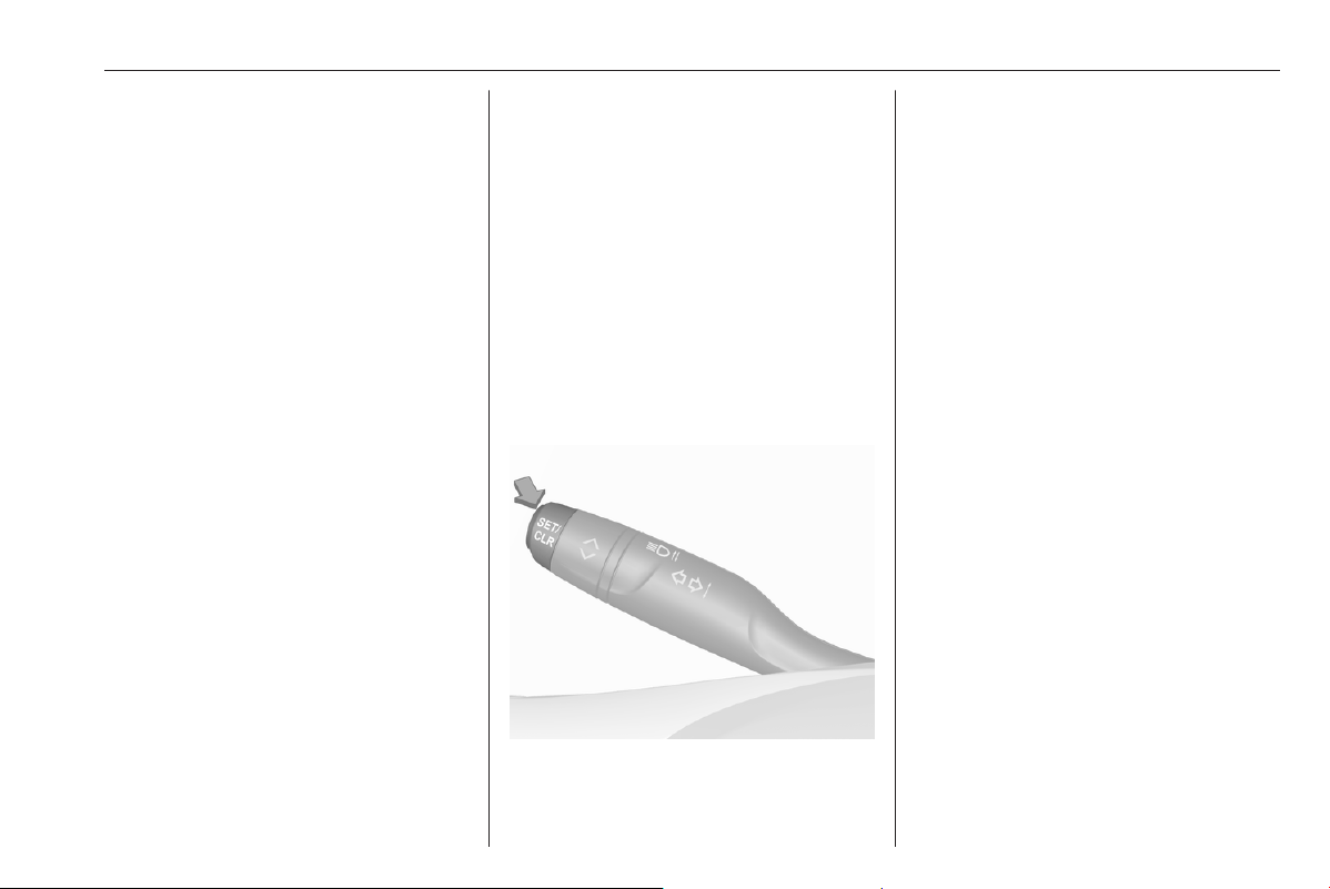
Instruments and controls 67
A required service due is displayed in
the Driver Information Centre for
several seconds after switching on
the ignition.
If no service is required for the next
1800 miles or more, no service
information appears in the display.
If service is required within the next
1800 miles, the remaining distance to
the next service due, the distance
travelled since the last service due or
the time period that remains to the
next service due is indicated for
several seconds. Simultaneously
symbol C illuminates temporary as
reminder.
If service is required in less than
600 miles, the remaining distance to
the next service due, the distance
travelled since the last service due or
the time period that remains to the
next service due is indicated for
several seconds. Simultaneously
C illuminates permanently as
reminder.
Overdued service is indicated by a
message in the Driver Information
Centre which indicates the overdued
distance. C flashes and then
illuminates permanently until service
is executed.
Reset of service interval
After each service, the service
indicator must be reset to ensure
proper functionality. It is
recommended to seek the assistance
of a workshop.
If service is executed by yourself,
operate as following:
● switch off ignition
● press and hold SET / CLR
● switch on ignition, the distance
indication begins a countdown
● when the display indicates =0,
release SET / CLR
The symbol C disappears.
Retrieving service information
The status of the service information
can be retrieved at any time via the
Info Display. Press Check in the
vehicle settings menu. The service
information is displayed for a few
seconds.
Info Display 3 78.
Service information 3 280.
Control indicators
The control indicators described are
not present in all vehicles. Depending
on the equipment, the position of the
control indicators may vary. When the
ignition is switched on, most control
indicators will illuminate briefly as a
functionality test.
The control indicator colours mean:
red : danger, important reminder
yellow : warning, information, fault

68 Instruments and controls
green : confirmation of activation
blue : confirmation of activation
white : confirmation of activation
grey : system paused, at least one
system limitation has been
detected
Control indicators are located in the
Driver Information Centre.
Driver Information Centre 3 77.
Overview
The numbers in the overview table
indicate what to do, when a control
indicator illuminates or flashes.
1 : only for information
2 : information and warning
3 : seek the assistance of a
workshop
4 : stop engine and seek the
assistance of a workshop
5 : have the cause of the fault
remedied immediately by a
workshop
6 : stop vehicle, do not continue the
journey and seek the assistance
of a workshop
1
1 Turn lights 3 69
a
2 Seat belt reminder
3 69
d
5 Airbag and belt
tensioners 3 70
g
1 Airbag deactivation
3 70
S
4 Charging system
3 70
W
5 Malfunction indicator
light 3 70
C
5 Service vehicle soon
3 71
+
4 Stop engine 3 71
X
4 System check 3 71
h
6 Brake and clutch
system 3 71
j
1 /
5
Parking brake 3 71
o
2 Automatic operation of
electric parking break
off 3 72
k
5 Electric parking brake
fault 3 72
1
1 Parking assist 3 73
i
2 Antilock brake system
(ABS) 3 72
Y
1 Gear shifting 3 72
L
2 Lane keep assist
3 72
O
2 Advanced lane keep
assist 3 73
J
2 /
5
Electronic Stability
Control and Traction
Control system 3 73
V
4 Engine coolant temper‐
ature high 3 73
z
1 Preheating 3 73
t
2 /
3
Exhaust filter 3 73
u
1 AdBlue 3 74
q
2 /
3
Deflation detection
system 3 74
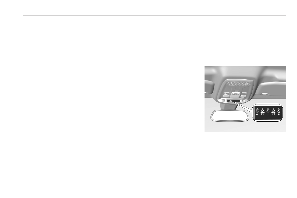
Instruments and controls 69
T
4 Engine oil pressure
3 74
r
2 Low fuel 3 75
n
1 Autostop 3 75
F
1 Exterior light 3 75
D
1 Low beam 3 75
A
1 High beam 3 76
B
1 High beam assist
3 76
G
1 Front fog lights 3 76
H
1 Rear fog light 3 76
y
1 Rain sensor 3 76
m
2 /
3
Active emergency
braking 3 76
4
2 /
3
Traffic sign assistant
3 76
P
2 Door open 3 77
i
5 Service vehicle soon
3 71
j
2 Charging cable
connected 3 75
READY 1 Vehicle ready 3 75
M
2 Reduced engine power
3 75
a
6 High voltage battery
temperature high
3 75
K
3 Pedestrian safety alert
fault 3 76
Turn lights
1 illuminates or flashes green.
Illuminates briefly
The parking lights are switched on.
Flashes
Turn lights or the hazard warning
flashers are activated.
Rapid flashing: failure of a turn light or
associated fuse.
Bulb replacement 3 258.
Turn lights 3 89.
Seat belt reminder
Seat belt reminder on all seats
a illuminates or flashes red in the
instrument cluster together with the
indication in the overhead console for
each seat belt.
● When the ignition is switched on,
a in the instrument cluster and
the symbol for the respective
seat in the overhead console
come on, if a seat belt is not
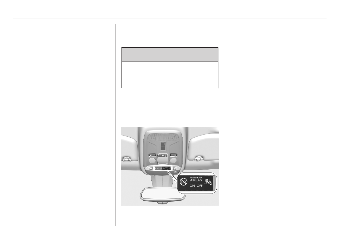
70 Instruments and controls
fastened. The front passenger
seat is only displayed when
occupied.
● After driving off, a in the
instrument cluster and the
symbol for the respective seat in
the overhead console flash for a
certain time together with a
chime. After a certain time of
driving a illuminates constantly
until the seat belt of the
respective seat has been
fastened or if any passenger has
unfastened the seat belt.
Seat belts 3 30.
Airbag and belt tensioners
d illuminates red.
When the ignition is switched on, the
control indicator illuminates for some
seconds. If it does not illuminate,
does not extinguish after some
seconds or illuminates whilst driving,
there is a fault in the airbag system.
Seek the assistance of a workshop.
The airbags and belt pretensioners
may fail to trigger in the event of an
accident.
Deployment of the belt pretensioners
or airbags is indicated by continuous
illumination of d.
9 Warning
Have the cause of the fault
remedied immediately by a
workshop.
Belt pretensioners 3 30.
Airbag system 3 33.
Airbag deactivation
H illuminates yellow.
The front passenger airbag is
activated.
g illuminates yellow.
The front passenger airbag is
deactivated.
Airbag deactivation 3 38.
Charging system
S illuminates red.
Illuminates when the ignition is
switched on and extinguishes shortly
after the engine starts.
Illuminates when the engine is
running
Stop, switch off engine. Vehicle
battery is not charging. Engine
cooling may be interrupted. The
brake servo unit may cease to be
effective. Seek the assistance of a
workshop.
Malfunction indicator light
W illuminates or flashes yellow.

Instruments and controls 71
Illuminates when the ignition is
switched on and extinguishes shortly
after the engine starts.
Illuminates when the engine is
running
Fault in the emission control system.
The permitted emission limits may be
exceeded. Seek the assistance of a
workshop immediately.
Flashes when the engine is
running
Fault that could lead to catalytic
converter damage. Ease up on the
accelerator until the flashing stops.
Seek the assistance of a workshop
immediately.
Service vehicle soon
C / i illuminates yellow.
C
Illuminates briefly when the ignition is
switched on.
May illuminate together with other
control indicators and a
corresponding message in the Driver
Information Centre.
Seek the assistance of a workshop
immediately.
i
Illuminates permanently when the
ignition is switched on.
A fault of the electric engine or the
high voltage battery has been
detected.
Seek the assistance of a workshop
immediately.
Stop engine
+ illuminates red.
Illuminates briefly when the ignition is
switched on.
Illuminates together with other control
indicators, accompanied by a warning
chime and a corresponding message
in the Driver Information Centre.
Stop engine immediately and seek
the assistance of a workshop.
System check
X illuminates yellow or red.
Illuminates yellow
A minor engine fault has been
detected.
Illuminates red
A major engine fault has been
detected.
Stop engine as soon as possible and
seek the assistance of a workshop.
Brake and clutch system
h illuminates red.
The brake and clutch fluid level is too
low.
9 Warning
Stop. Do not continue your
journey. Consult a workshop.
Brake fluid 3 254.
Parking brake
j illuminates or flashes red.

72 Instruments and controls
Illuminates
Parking brake is applied 3 183.
Flashes
Electric parking brake is not applied
automatically. The application or the
release are faulty.
9 Warning
Have the cause of the fault
remedied immediately by a
workshop.
Electric parking brake fault
k illuminates yellow.
Illuminates
Electric parking brake has a fault
3 183.
9 Warning
Have the cause of the fault
remedied immediately by a
workshop.
Automatic operation of
electric parking brake off
o illuminates yellow.
Illuminates
Automatic operation is deactivated or
faulty. In the event of a fault, o
illuminates together with other control
indicators or it is accompanied by a
corresponding message in the Driver
Information Centre.
Activate automatic operation again or
have the cause remedied by a
workshop in the event of a fault.
Automatic operation 3 183.
Antilock brake system
(ABS)
i illuminates yellow.
Illuminates for a few seconds after the
ignition is switched on. The system is
ready for operation when the control
indicator extinguishes.
If the control indicator does not
extinguish after a few seconds, or if it
illuminates while driving, there is a
fault in the ABS. The brake system
remains operational but without ABS
regulation.
Antilock brake system 3 182.
Gear shifting
Y or Z with the number of a higher
or lower gear is indicated, when
upshifting or downshifting is
recommended for fuel saving
reasons.
On vehicles with automatic
transmission, the system is only
active in manual mode.
Automatic transmission 3 177.
Lane keep assist
L illuminates or flashes yellow.
Illuminates yellow
A fault has been detected.
Flashes yellow
The system is correcting the
unintended lane change.
Lane keep assist 3 224.

Instruments and controls 73
Advanced lane keep assist
O illuminates grey, green or yellow.
Illuminates grey
The system is paused. At least one
system limitation has been detected.
Illuminates green
The system is active and ready to
operate.
Illuminates yellow
The system has a fault.
Advanced lane keep assist 3 226.
Parking assist
1 flashes yellow as soon as an
obstacle gets closer to the vehicle.
Parking assist 3 205
Electronic Stability Control
and Traction Control system
J illuminates or flashes yellow.
Illuminates
A fault in the system is present.
Continued driving is possible. Driving
stability, however, may deteriorate
depending on road surface
conditions.
Have the cause of the fault remedied
by a workshop.
After reconnecting the vehicle
battery, (e.g. after maintenance
work), J is illuminated for several
seconds. After this time period, J
extinguishes. This is a normal
procedure, the vehicle does not need
any assistance.
Flashes
The system is actively engaged.
Engine output may be reduced and
the vehicle may be braked
automatically to a small degree.
Electronic Stability Control and
Traction Control system 3 186.
Engine coolant temperature
V illuminates red.
Illuminates red when the engine is
running
Stop, switch off engine.
Caution
Coolant temperature too high.
Check coolant level immediately
3 253.
If there is sufficient coolant, consult a
workshop.
Preheating
z illuminates yellow.
Preheating of diesel engine is
activated. Only activates when
outside temperature is low. Start the
engine when control indicator
extinguishes.
Starting the engine 3 166.
Exhaust filter
t illuminates yellow.
The exhaust filter requires cleaning.

74 Instruments and controls
Continue driving until the control
indicator extinguishes.
Illuminates temporarily
Start of saturation of the exhaust filter.
Start cleaning process as soon as
possible by driving at a vehicle speed
of at least 40 mph.
Illuminates constantly
Indication of a low additive level. Seek
the assistance of a workshop.
Exhaust filter 3 171.
AdBlue
u flashes or illuminates yellow.
Illuminates yellow
The remaining driving range is
between 500 miles and 1500 miles.
Flashes yellow
The remaining driving range is
between 0 and 500 miles.
AdBlue level is low. Refill AdBlue
soon to avoid prevention of the
engine start.
AdBlue 3 172.
Deflation detection system
q illuminates or flashes yellow.
Illuminates
Tyre pressure loss in one or more
wheels. Stop immediately and check
tyre pressure.
Flashes
Fault in system. Consult a workshop.
Deflation detection system 3 263.
Engine oil pressure
T illuminates red.
Illuminates when the ignition is
switched on and extinguishes shortly
after the engine starts.
Illuminates when the engine is
running
Caution
Engine lubrication may be
interrupted. This may result in
damage to the engine and / or
locking of the drive wheels.
1. Select neutral gear.
2. Move out of the flow of traffic as
quickly as possible without
impeding other vehicles.
3. Switch off ignition.

Instruments and controls 75
9 Warning
When the engine is off,
considerably more force is needed
to brake and steer. During an
Autostop the brake servo unit will
still be operational.
Do not remove key until vehicle is
stationary, otherwise the steering
wheel lock could engage
unexpectedly.
Keep engine turned off and let the
vehicle be towed to a workshop.
Low fuel
r illuminates yellow.
Level in fuel tank is too low.
Refuelling 3 241.
Bleeding the diesel fuel system
3 257.
Charging cable connected
j illuminates red.
The vehicle plug of the charging cable
is still connected to the charge port.
The vehicle cannot be started.
Disconnect the vehicle plug from the
charge port and close the charge port
flap.
Charging 3 232.
Vehicle ready
READY illuminates green. The
vehicle is ready to be driven.
Reduced engine power
M illuminates yellow.
The charging level of the high voltage
battery is low. Only reduced engine
power is available.
High voltage battery
temperature high
a illuminates red.
Illuminates briefly when the ignition is
switched on.
Illuminates together with other control
indicators, accompanied by a warning
chime and a corresponding message
in the Driver Information Centre.
Stop engine immediately and
evacuate the vehicle.
Autostop
n illuminates or flashes green.
Illuminates green
Engine is in an Autostop.
Flashes green
Autostop is temporarily unavailable,
or Autostop mode is invoked
automatically.
Stop-start system 3 167.
Exterior light
F illuminates green.
The exterior lights are on 3 84.
Low beam
D illuminates green.

76 Instruments and controls
Illuminated when low beam is on.
High beam
A illuminates blue.
Illuminates when high beam is on or
during headlight flash 3 85.
High beam assist
B illuminates green.
The high beam assist is activated
3 85.
LED headlights
C illuminates and a warning
message is displayed in the Driver
Information Centre.
Seek the assistance of a workshop.
Front fog lights
G illuminates green.
The front fog lights are on 3 89.
Rear fog light
H illuminates yellow.
The rear fog light is on 3 90.
Rain sensor
y illuminates green.
Illuminated when rain sensor position
on wiper lever is selected.
Windscreen wiper and washer 3 58.
Pedestrian safety alert fault
K illuminates yellow.
The pedestrian safety alert is not
working.
Active emergency braking
m illuminates or flashes yellow.
Illuminates
The system has been deactivated or
a fault has been detected.
Additionally, a warning message is
displayed in the Driver Information
Centre.
Check the reason of the deactivation
3 200 and in case of a system fault,
seek the assistance of a workshop.
Notice
m also illuminates if the seat belts
of the front passengers are not
fastened. In this case, active
emergency braking is deactivated.
Flashes
The system is actively engaged and
brakes automatically the vehicle.
Active emergency braking 3 200.
Forward collision alert 3 198.
Front pedestrian protection 3 204.
Traffic sign assistant
4 illuminates for a few seconds or
permanently.
Illuminates for a few seconds
If the vehicle exceeds the speed limit
provided by the traffic sign assistant,
the speed limit displayed in the Driver
Information Centre flashes and an
audible signal is given. If flashing and
audible signal are deactivated, 4
illuminates for a few seconds.
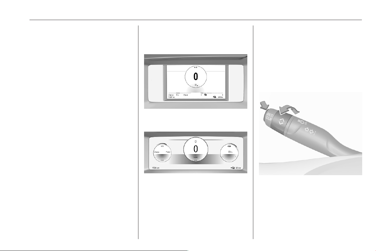
Instruments and controls 77
Illuminates permanently
If the traffic sign assistant has a
failure, 4 illuminates permanently.
Consult a workshop.
Traffic sign assistant 3 220.
Door open
P illuminates red.
A door or the tailgate is open.
Displays
Driver Information Centre
Depending on version, two variants
are available.
In addition to warning lights, gauges
and indicators, the following
information is available:
● trip odometer
● gear shift indication
● service information
● vehicle and warning messages
● driver assistance systems
● pop-up messages
● infotainment information
Selecting menus and functions
The menus and functions can be
selected via the buttons on the
indicator lever.
Turn the adjuster wheel to select a
view of the Driver Information Centre.
Different views are available for
driving and navigation information.
Also a personalised view is
selectable.
Press SET / CLR to confirm or reset
a function.
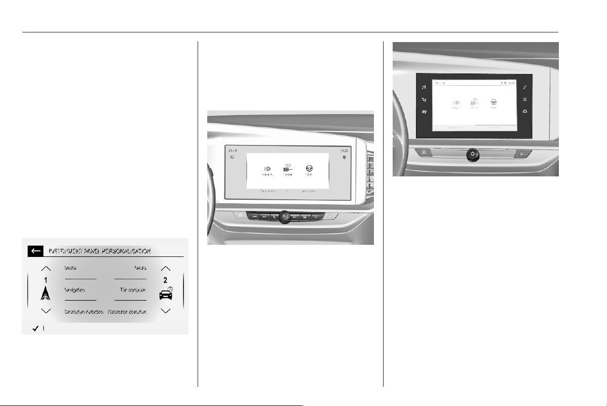
78 Instruments and controls
Vehicle and service messages are
popped up in the Driver Information
Centre, if required. Scroll messages
by turning the adjuster wheel.
Confirm messages by pressing
SET / CLR.
Vehicle messages 3 80.
Personalised view
Personalised views can be selected
by turning the adjuster wheel.
The personalised views can be
adjusted in the settings menu in the
Info Display.
Choose the content, e.g. the
navigation map or current trip
information, and confirm the settings.
Info Display
The illustrations show different
variants of the infotainment system.
The Info Display can indicate:
● time 3 61
● outside temperature 3 60
● date 3 61
● infotainment system 3 93
● indication of rear view camera
3 217
● navigation 3 114
● vehicle and system messages
3 80
● settings for vehicle
personalisation 3 81
● AdBlue range 3 172
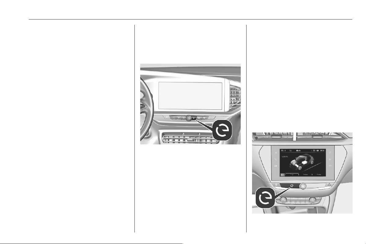
Instruments and controls 79
Selecting menus and settings
There are three options to operate the
display:
● via buttons next to the display
● by touching the touchscreen with
the finger
● via speech recognition
Notice
Some menu entries are only
available when ignition is switched
on, when combustion engine is
running or when electric engine is
ready or until a specific speed.
Button and touch operation
Press ) to switch on the display.
Press : to select system settings
(units, language, time and date).
Press _ to select vehicle settings or
driving functions.
Touch required menu display icon or
a function with the finger.
Confirm a required function or
selection by touching.
Touch 3 or & on the display to exit
a menu without changing a setting.
Infotainment system 3 93.
Flow
This menu displays the current
energy flow within the electric system.
1. Press m.
2. Select Flow.
Different colours show the engery
flow.
● green: electric engine operating
● blue: regenerating energy
Average consumption
This menu displays the average
power consumption during the
current trip.
● green: electric energy consumed
● blue: electric energy generated
from the braking and
deceleration phases of the
vehicle used to recharge the
battery
The current trip is subdivided into time
steps. For each time step, the
average consumption is displayed.
The time steps can be modified.
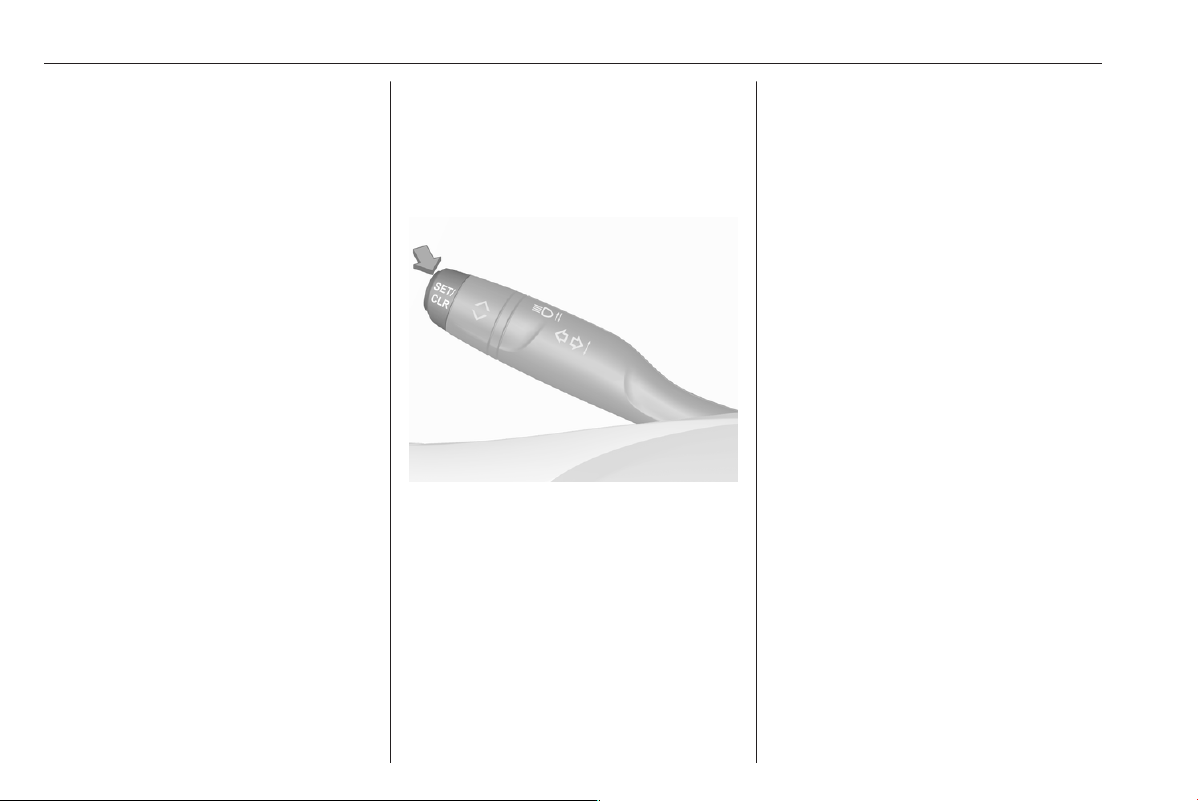
80 Instruments and controls
1. Press m.
2. Select Statistics.
3. Press + and - to modify the time
steps.
Vehicle messages
Messages are indicated in the Driver
Information Centre, in some cases
together with a warning chime.
Press SET / CLR to confirm a
message.
Vehicle and service messages
The vehicle messages are displayed
as text. Follow the instructions given
in the messages.
Messages in the Info Display
Some important messages may
appear additionally in the Info
Display. Some messages only pop-
up for a few seconds.
Warning chimes
The warning chime regarding not
fastened seat belts has priority over
any other warning chime.
Whenever a warning chime sounds,
pay attention to the messages
displayed and the warning lights in
the Driver Information Centre.
When a failure is detected in the
sound module C appears in the
Driver Information Centre,
accompanied by a display message.
No warning chime will sound, also not
for the driver assistance systems.
When starting the engine or whilst
driving
A warning chime will sound when
● a seat belt is not fastened
● a door or the tailgate is not fully
closed
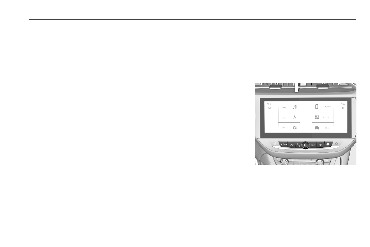
Instruments and controls 81
● a certain speed is exceeded with
parking brake applied
● cruise control deactivates
automatically
● a programmed speed or speed
limit is exceeded
● a warning message appears in
the Driver Information Centre
● the electronic key is not in the
passenger compartment
● the parking assist detects an
object
● an unintended lane change
occurs
● hands-off driving is recognised
● drowsiness of the driver is
recognised
● a vehicle directly ahead is
approached too quickly
● the exhaust filter has reached the
maximum filling level
If several warnings appear at the
same time, only one warning chime
will sound.
When the vehicle is parked and /
or the driver's door is opened
A warning chime will sound when
● the exterior lights are on
● the key is in the ignition switch
During an Autostop
● If the driver's door is opened.
● If any condition for a restart of the
engine is not fulfilled.
Vehicle personalisation
The vehicle's behaviour can be
personalised by changing the settings
in the Info Display.
Some functions are only displayed or
active when the engine is running.
The illustrations show different
variants of the infotainment system.
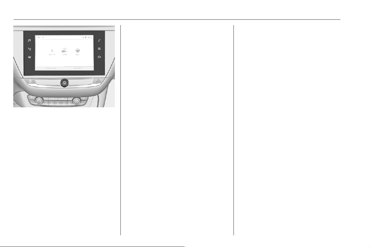
82 Instruments and controls
Touch _ to display the vehicle
personalisation menu.
Lighting, comfort and safety settings
are adjustable.
Telematics services
Vauxhall Connect
Vauxhall Connect comprises multiple
connected services accessible via
app, online or within the vehicle.
Notice
Full functionality of
Vauxhall Connect is subject to
registration and proper activation.
Connected services may include live
navigation such as online traffic
information and vehicle status and
information such as maintenance
alerts.
Services accessible within the vehicle
also include emergency call and
breakdown call. These functions are
automatically activated. Terms and
conditions apply.
Emergency call 3 82.
Breakdown call
Pressing the . button in the
overhead console for more than two
seconds connects to a roadside
assistance service provider.
For information about coverage and
scope of services of the roadside
assistance, please refer to the
information provided by the Vauxhall
Retailer with the order form.
Privacy settings
Privacy settings of Vauxhall Connect
can be configured. This will impact
the set of data being sent, e.g., in
case a breakdown call is triggered.
The emergency call function and the
traffic sign assistant will not be
impacted.
Depending on version, the privacy
settings can be changed by
simultaneously pressing . and
SOS in the overhead console or via
the system settings menu in the Info
Display.
Emergency call
Notice
In order to be available and
operational, the system requires
functioning vehicle electrics, mobile
service and GPS or GLONASS

Instruments and controls 83
satellite link. Depending on
equipment, a backup battery is
used.
Notice
The service is only available for
markets where it is legally required.
Furthermore, it depends on the
availability of the emergency centres
and the infrastructure in the country.
Status LED in the overhead
console
Illuminates green and red and
extinguishes after a short time, when
the ignition is switched on: the system
works properly.
Illuminates red: fault in the system.
Contact a workshop.
Flashes red: backup battery needs
replacement. Contact a workshop.
Emergency call
The emergency call function will
establish a connection to the nearest
public safety answering point (PSAP).
A minimum set of data including
vehicle and location information will
be sent to the PSAP.
In case of an emergency, press the
red SOS button in the overhead
console for more than two seconds.
The LED flashes green to confirm that
a connection to the nearest PSAP is
being established. The LED
illuminates steadily as long as the call
is active.
Pressing the SOS button immediately
a second time will terminate the call.
The LED switches off.
Automatic crash notification
In case of an accident with airbag
deployment and without damage of
needed hardware, an automatic
emergency call is established and an
automatic crash notification will be
transmitted to the next PSAP.
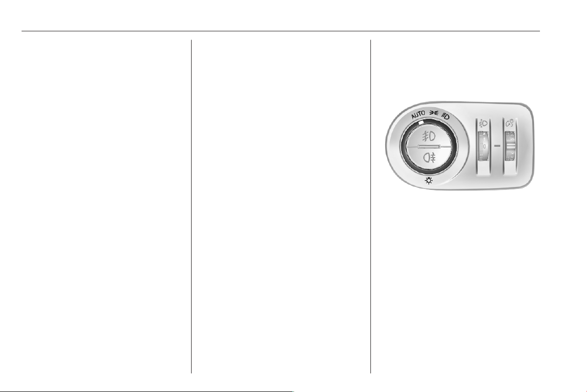
84 Lighting
Lighting
Exterior lighting ............................ 84
Light switch ................................ 84
Automatic light control ............... 85
High beam ................................. 85
High beam assist ....................... 85
Headlight flash ........................... 86
Headlight range adjustment ...... 86
Headlights when driving
abroad ...................................... 86
Daytime running lights ............... 86
Matrix-LED headlights ............... 87
Hazard warning flashers ............ 88
Turn lights .................................. 89
Front fog lights ........................... 89
Rear fog light ............................. 90
Parking lights ............................. 90
Reversing lights ......................... 90
Misted light covers ..................... 90
Interior lighting ............................. 91
Instrument panel illumination
control ....................................... 91
Interior lights .............................. 91
Reading lights ............................ 91
Sunvisor lights ........................... 91
Lighting features .......................... 92
Entry lighting .............................. 92
Exit lighting ................................ 92
Vehicle locator lighting .............. 92
Peripheral lighting ...................... 92
Battery discharge protection ...... 92
Exterior lighting
Light switch
Turn light switch:
AUTO : automatic light control
switches automatically
between daytime running
light and headlight
8
: sidelights
9
: headlights
Control indicator 8 3 75.
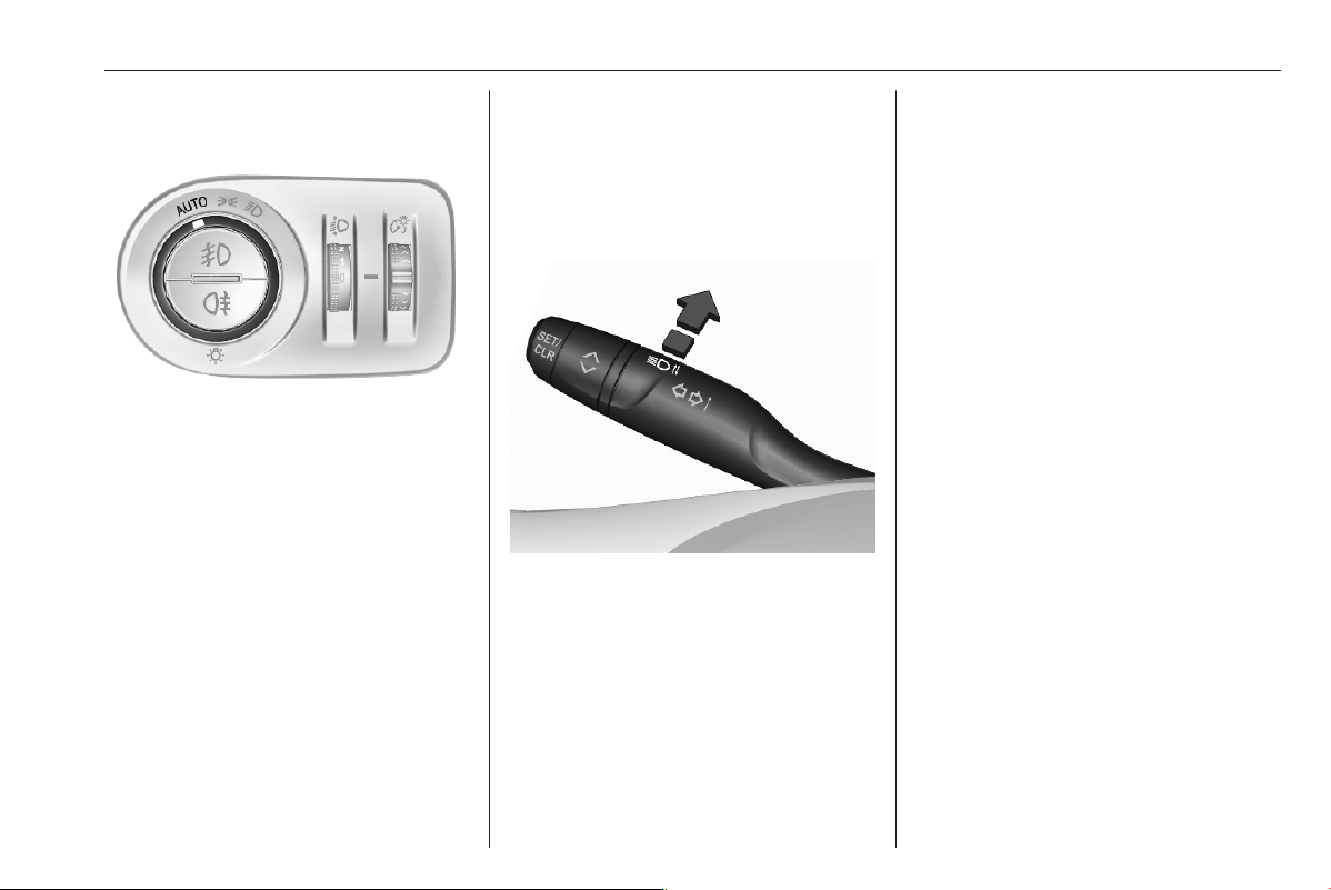
Lighting 85
Automatic light control
When the automatic light control
function is switched on, the system
switches between daytime running
lights and headlights automatically
depending on the external lighting
conditions and information given by
the wiper system.
Daytime running light 3 86.
Automatic headlight activation
During poor lighting conditions the
headlights are switched on.
Additionally, headlights are switched
on if the windscreen wipers have
been activated for several wipes.
Tunnel detection
When a tunnel is entered, headlights
are switched on immediately.
High beam
Push to switch from low to high beam.
Push again to deactivate high beam.
High beam assist
The system switches from low beam
to high beam and vice versa to
prevent glaring. Once activated, high
beam assist remains active and
switches high beam on and off
depending on surrounding
conditions. The latest setting of the
high beam assist will remain after the
ignition is switched on again.
Glare-free high beam for Matrix-LED
headlights 3 87.
Activation
The high beam assist can be
activated via the vehicle settings
menu in the Info Display.
Info Display 3 78.
High beam is switched on
automatically in dark surroundings at
a speed above 28 mph. High beam is
switched off at a speed below
22 mph, but high beam assist remains
active.
The green control indicator B
illuminates continuously when the
high beam assist is activated, the blue
A illuminates when high beam is on.
Control indicator B 3 76, A 3 76.
High beam assist switches
automatically to low beam when:
● Driving in urban areas.
● Camera detects heavy fog.
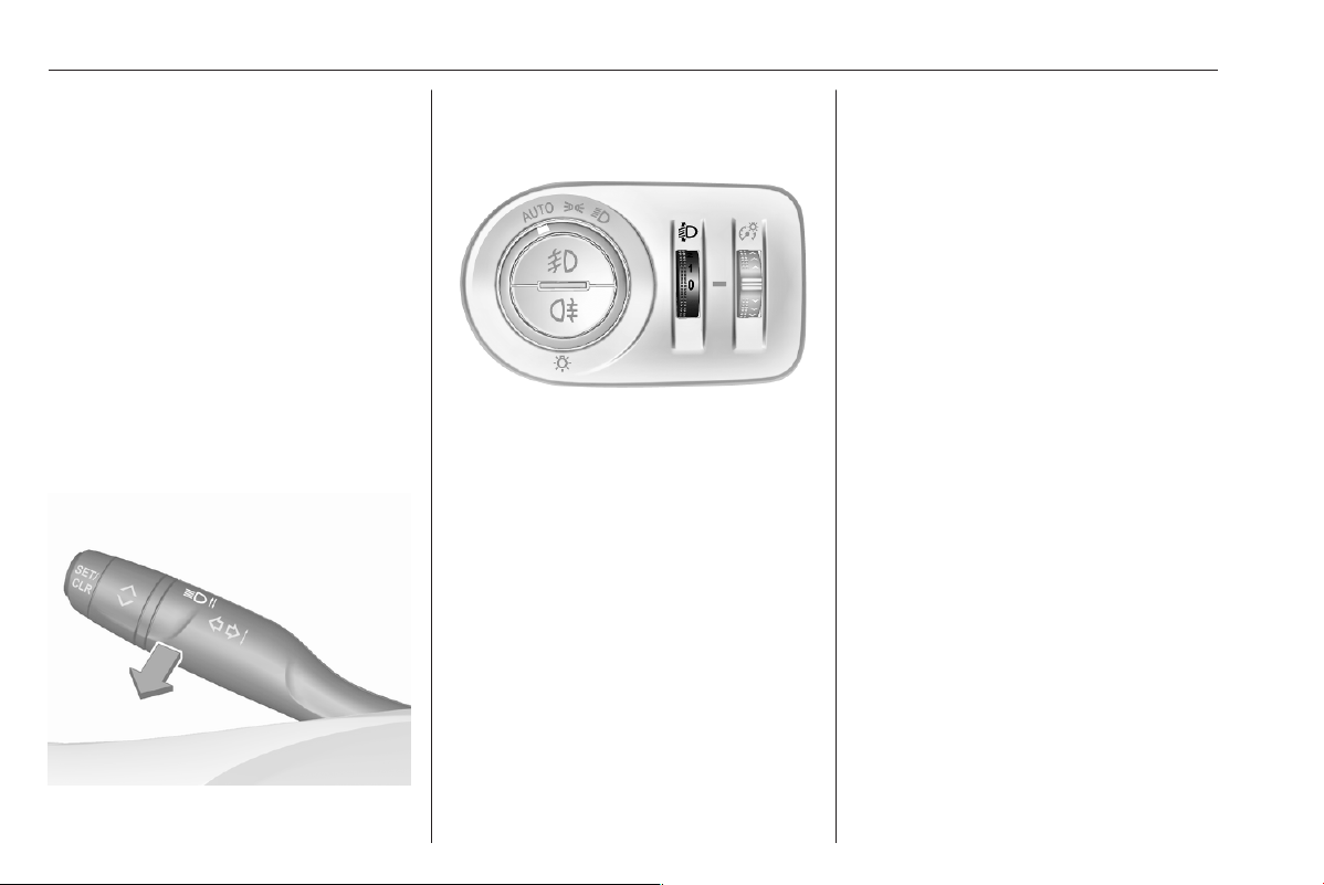
86 Lighting
● Rear fog light is switched on.
● Oncoming or preceding vehicles
are detected by the camera.
If there are no restrictions detected,
the system switches back to high
beam.
Deactivation
The system can be deactivated via
the vehicle settings menu in the Info
Display.
Info Display 3 78.
Headlight flash
Pull to activate the headlight flash.
Headlight range adjustment
Headlight range can be adjusted
manually if vehicle is not equipped
with Matrix-LED headlights. Matrix-
LED headlights are adjusted
automatically.
To adapt headlight range manually to
the vehicle load to prevent dazzling,
turn thumb wheel X to required
position.
ICE
0 : front seats occupied
1 : all seats occupied
2 : all seats occupied and load
compartment laden
3 : driver's seat occupied and load
compartment laden
BEV
0 : front seats occupied
1 : all seats occupied with or without
load compartment laden
2 : driver's seat occupied and load
compartment laden
3 : not used
Propulsion types 3 4.
Headlights when driving
abroad
When driving in countries where
traffic drives on the opposite side of
the road, the headlights do not have
to be adjusted.
Daytime running lights
Daytime running lights increase
visibility of the vehicle during daylight.
Automatic light control 3 85.
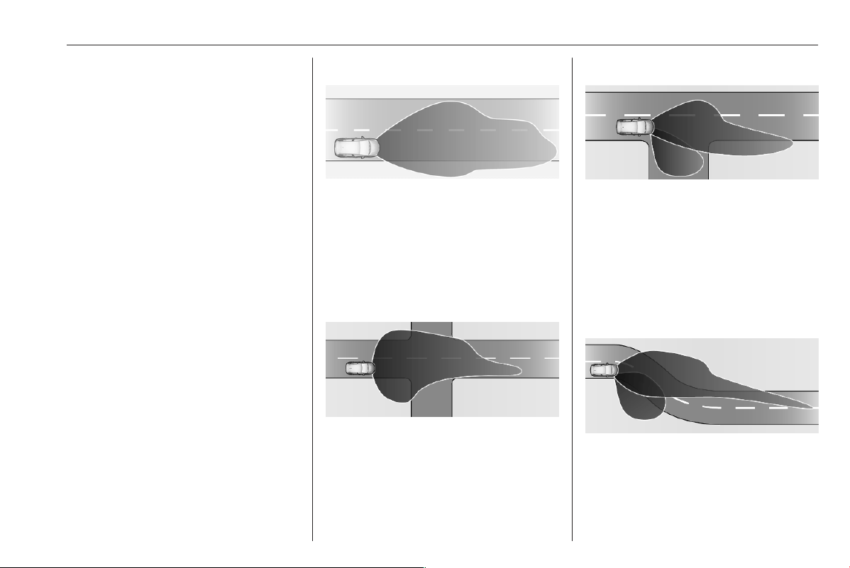
Lighting 87
Matrix-LED headlights
The Matrix-LED headlight system
contains a variety of particular LEDs
in each headlight which enables the
control of the adaptive forward
lighting functions.
Light distribution and intensity of light
are variably triggered depending on
the lighting conditions, road type and
driving situation. The vehicle adapts
the headlights automatically to the
situation to enable optimal light
performance for the driver.
The adaptive forward lighting and the
Matrix-LED headlights functions can
be deactivated or activated in the
vehicle personalisation menu.
Vehicle personalisation 3 81.
Info Display 3 78.
The glare-free high beam function of
the Matrix-LED headlights are only
available with light switch in position
AUTO.
Country light
Activated automatically at a speed
above 30 mph when driving in rural
areas. The illumination of the current
lane and the side of the road is
adapted. Oncoming and preceding
vehicles are not dazzled.
Town light
Activated automatically at a speed up
to approx. 30 mph. The light is wide
and symmetrical.
Cornering light
Activated at a speed of up to 25 mph
when turning off. The light consists of
particular LEDs which illuminate the
direction of travel. These LEDs are
triggered depending on the steering
angle or the activation of the turn
lights.
Curve light
Particular LEDs, based on steering
angle and speed, are additionally
triggered to improve lighting in
curves. This function is activated at
speeds from 25 mph to 43 mph.
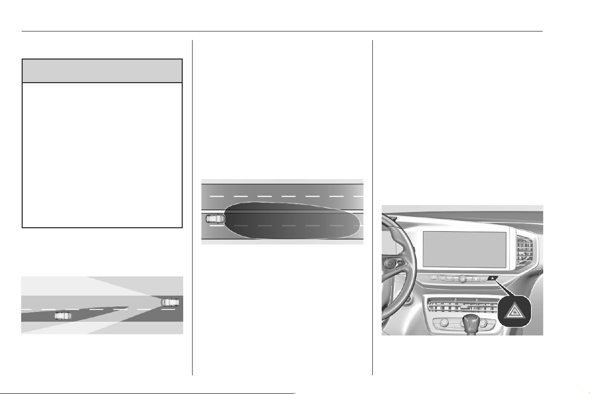
88 Lighting
Glare-free high beam
9 Warning
The glare-free high beam function
may dazzle other road users when
the vehicle is driven in countries
where traffic moves on the
opposite side of the road. E.g.
when the vehicle was designed for
left hand drive traffic and it is
driven in a country with right hand
drive traffic.
Switch off glare-free high beam
function whenever you are driving
in countries mentioned above!
The system enables a glare-free high
beam when driving in dark
surroundings.
Each LED on right or left side is
triggered or faded out particularly
according to the traffic situation. This
gives the best light distribution
without dazzling other road users.
Glare-free high beam is switched on
automatically at a speed above
28 mph. It is switched off at a speed
below 22 mph, but the system
remains active.
Motorway mode
Activated automatically at a speed
above 65 mph. Illumination is
adapted to the higher speed driven on
motorways. If there is no oncoming
traffic, the visibility on the side of the
vehicle is increased. When following
vehicles ahead or passing, dazzling
for these vehicles is reduced.
Fault in LED headlight system
When the system detects a failure in
the LED headlight system, it selects a
preset position to avoid dazzling of
oncoming traffic. A warning is
displayed in the Driver Information
Centre.
After reconnecting the vehicle
battery, the system needs a
recalibration by driving a short
distance.
Hazard warning flashers
Operated by pressing c.
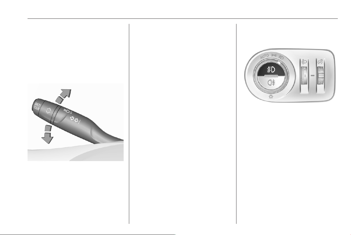
Lighting 89
When braking in an emergency, the
hazard warning flashers are switched
on automatically, depending on the
force of deceleration. They are
switched off automatically, as soon as
the vehicle is accelerated again.
Turn lights
up : right turn lights
down : left turn lights
A resistance point can be felt when
moving the indicator lever.
Constant flashing is activated when
the indicator lever is being moved
beyond the resistance point. It is
deactivated when the steering wheel
is moved in the opposite direction or
indicator lever is manually moved
back to its neutral position.
After 20 seconds the volume of the
audible signal will increase if the
speed is above 50 mph.
Activate temporary flashing by
holding the indicator lever just before
the resistance point. Turn lights will
flash until indicator lever is being
released.
To activate three flashes, tap the
indicator lever briefly without passing
the resistance point.
Front fog lights
Operated by pressing >.
Light switch in position AUTO:
switching on front fog lights will switch
headlights on automatically.
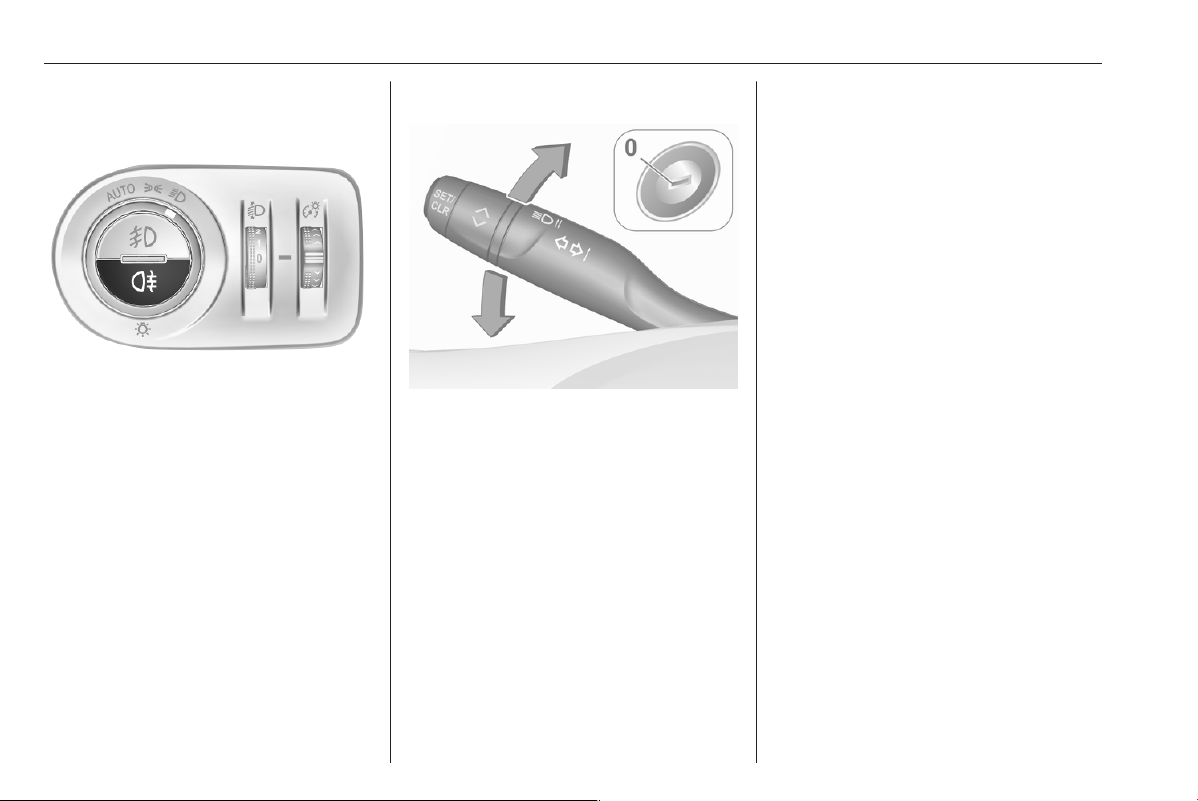
90 Lighting
Rear fog light
Operated by pressing H.
Light switch in position AUTO:
switching on rear fog light will switch
headlights on automatically.
Light switch in position 8: rear fog
light can only be switched on with
front fog lights.
The vehicle rear fog light is
deactivated when a plug is connected
to the power outlet of the trailer hitch.
Parking lights
When the vehicle is parked, the
parking lights on one side can be
activated:
1. Switch off ignition.
2. Move the lever all the way up
(right parking lights) or down (left
parking lights).
Confirmed by a signal and the
corresponding turn lights control
indicator.
Reversing lights
The reversing light comes on when
reverse gear is selected.
Misted light covers
The inside of the light housing may
mist up briefly in poor, wet and cold
weather conditions, in heavy rain or
after washing. The mist disappears
quickly by itself. To help, switch on the
headlights.
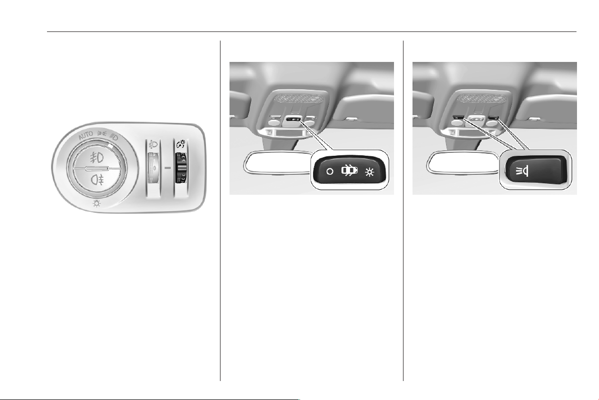
Lighting 91
Interior lighting
Instrument panel
illumination control
Brightness of the following lights can
be adjusted when the exterior lights
are on:
● instrument panel illumination
● Info Display
● illuminated switches and
operation elements
Turn thumb wheel F and hold until
the desired brightness is obtained.
Interior lights
Operate rocker switch:
;
: automatic switching on
and off
press § : on
press 2 : off
Notice
In the event of an accident with
airbag deployment the courtesy
lights are turned on automatically.
Reading lights
Operated by pressing z.
Sunvisor lights
Illuminates when the cover is opened.

92 Lighting
Lighting features
Entry lighting
Welcome lighting
Some or all of the following lights are
switched on for a short time by
unlocking the vehicle with the radio
remote control:
● headlights
● interior lights
The number of activated lights
depends on the surrounding light
conditions.
The lighting switches off immediately
when the ignition is switched on.
Starting off 3 164.
This function can be activated or
deactivated in the vehicle
personalisation.
Vehicle personalisation 3 81.
The following lights will additionally
switch on when the driver's door is
opened:
● illumination of some switches
● Driver Information Centre
● door pocket lights
Exit lighting
The following lights are switched on
when the ignition is switched off:
● headlights
● interior lights
● centre console lighting
They will switch off automatically after
a delay. This function works only in
the dark.
Vehicle locator lighting
This function allows to locate the
vehicle, e.g., in weak lighting
conditions using the remote control.
The headlights come on and the turn
lights flash for 10 seconds.
Press b on the remote control.
Peripheral lighting
Peripheral lighting allows you to
switch on the position lights, low
beam and number plate lighting using
the remote control.
Press D on the remote control to
switch on peripheral lighting.
Press D a second time to switch off
peripheral lighting.
Battery discharge protection
To prevent discharge of the vehicle
battery when the ignition is switched
off, some interior lights are switched
off automatically after some time.

Infotainment system 93
Infotainment system
Multimedia Navi Pro ..................... 93
Audio ....................................... 108
External devices ...................... 111
Navigation ............................... 114
Speech recognition .................. 125
Phone ...................................... 127
Multimedia ................................. 132
Audio ....................................... 141
External devices ...................... 143
Speech recognition .................. 146
Phone ...................................... 148
Multimedia Navi Pro
Introduction
Important information on operation
and traffic safety
9 Warning
Drive safely at all times. Only
operate the Infotainment system if
the traffic conditions allow a safe
usage.
In the interest of safety, it might be
appropriate to stop the vehicle
before operating the Infotainment
system (e.g. for entries of
addresses).
9 Warning
The usage of the navigation
system does not release the driver
from the responsibility for a
correct, vigilant attitude in road
traffic. Always follow the
applicable traffic rules.
9
Warning
In some areas one-way streets
and other roads and entrances
(e.g. pedestrian zones) that you
are not allowed to turn into are not
marked on the map. In such areas
the Infotainment system may
issue a warning that must be
accepted. Here you must pay
particular attention to one-way
streets, roads and entrances that
you are not allowed to drive into.
Radio reception
Radio reception may be disrupted by
static, noise, distortion or loss of
reception due to:
● changes in distance from the
transmitter
● multi-path reception due to
reflection
● shadowing
Theft-deterrent feature
The Infotainment system is equipped
with an electronic security system for
the purpose of theft deterrence.

94 Infotainment system
The Infotainment system therefore
functions only in your vehicle and is
worthless to a thief.
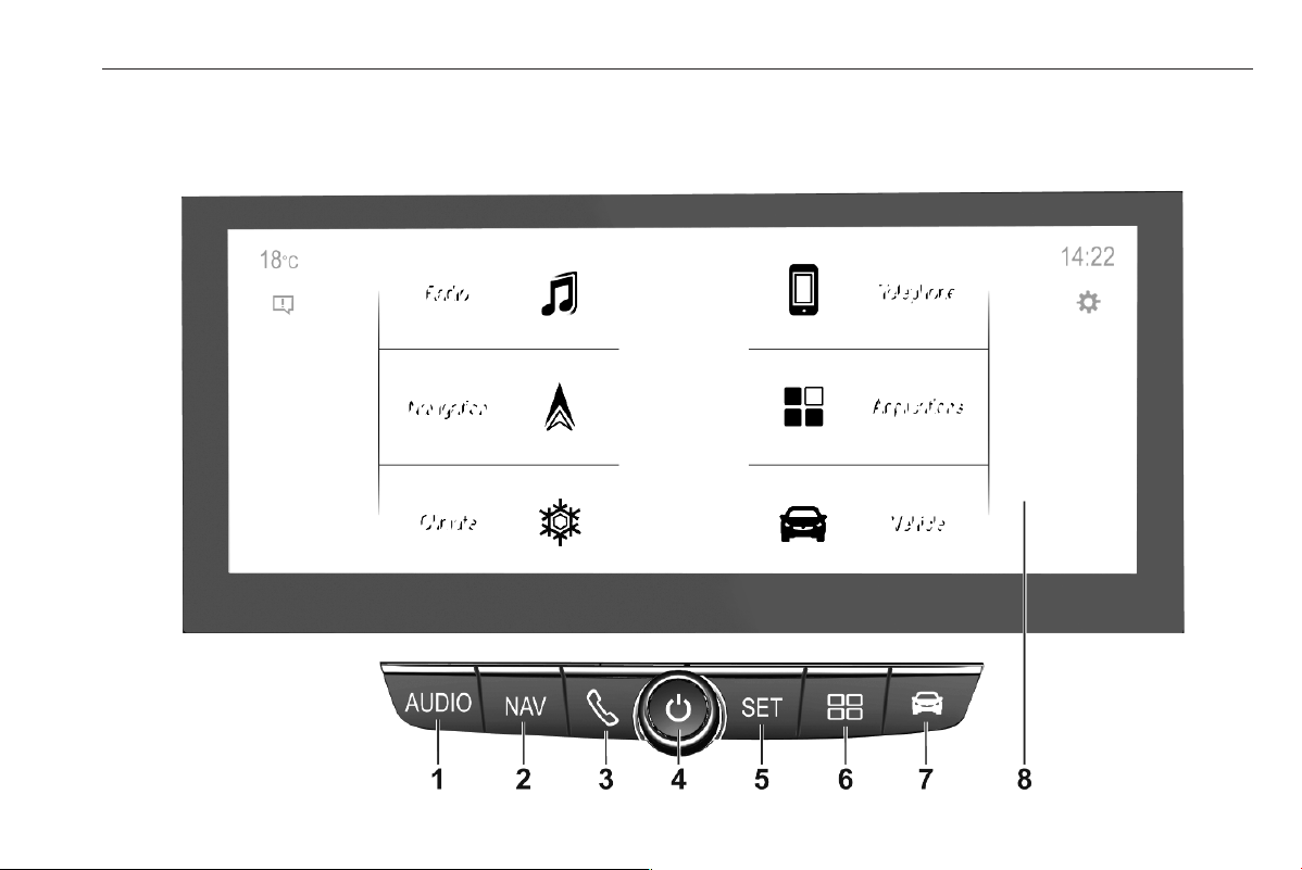
Infotainment system 95
Multimedia Navi Pro
Control panel – Multimedia Navi Pro

96 Infotainment system
1 AUDIO
Open audio menu:
Radio ................................... 108
External devices (USB,
Bluetooth) ............................ 111
2 NAV
Display embedded
navigation map ................... 114
3 6
Open phone menu .............. 127
Display phone projection
screen when phone
projection is active .............. 111
4 )
If switched off: switch
power on / off
If switched on: mute system
Turn: adjust volume
5 SET / m
Open settings menu
or open charging settings
(BEV) .................................... 78
6 d
Open apps menu ................ 111
7 7
Open vehicle settings menu . 81
8 Info Display
Home menu will be
displayed by a 3-finger
touch on screen
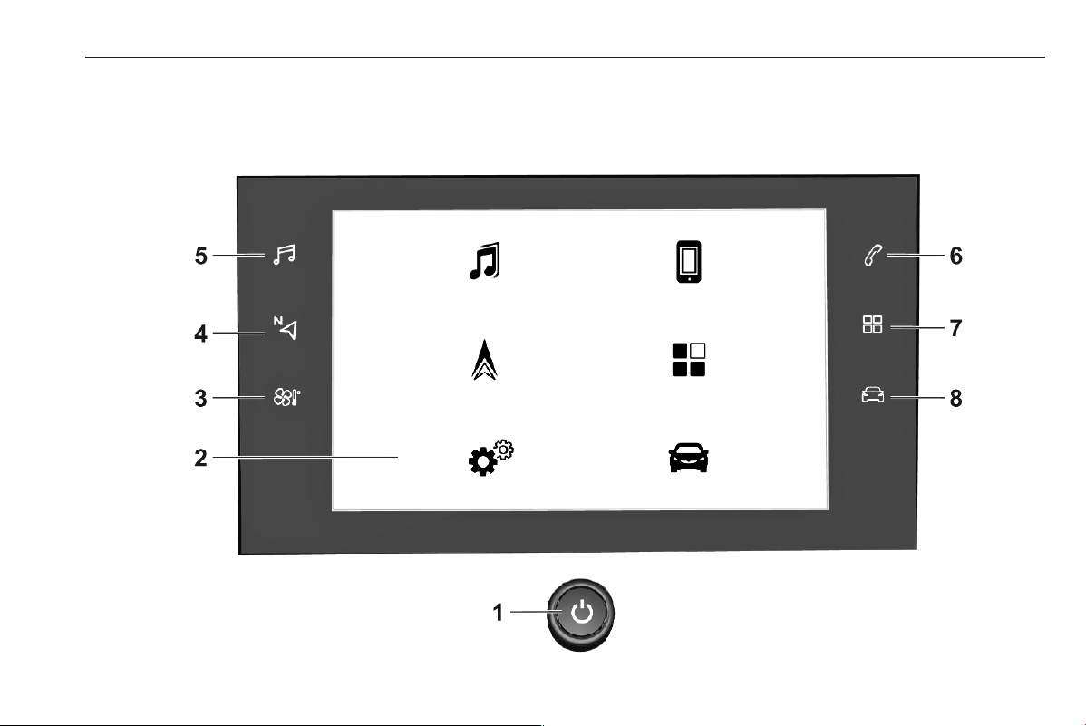
Infotainment system 97
Multimedia Navi Pro
Control panel – Multimedia Navi

98 Infotainment system
1 )
If switched off: switch
power on / off
If switched on: mute system
Turn: adjust volume
2 Info Display
Home menu will be
displayed by a 3-finger
touch on screen
3 h
Open climate menu if available
4 c
Display embedded
navigation map ................... 114
5 b
Open audio menu:
Radio ................................... 108
External devices (USB,
Bluetooth) ............................ 111
6 a
Open phone menu .............. 127
Display phone projection
screen when phone
projection is active .............. 111
7 d
Open apps menu ................ 111
8 _
Open vehicle settings menu . 81
Steering wheel controls
1 SRC (Source)
Select audio source,
confirm selection with A
Long press: mute system
2 c / d
Select next / previous
preset radio station when
radio active .......................... 108
or select next / previous
track / picture when
external devices active ....... 111

Infotainment system 99
or select next / previous
entry in station list, media
list, call / contacts list when
operation started via
steering wheel controls
Confirm selection with A
3 A
Confirm selected item
or open station list, media list
4 e
Activate / deactivate mute
function
5 Y / Z
Turn upwards /
downwards: increase /
decrease volume
6 6
Short press: accept
incoming call
Long press: reject
incoming call, hang up call .. 127
or open call / contacts list ...127
If phone call active: open
call in progress menu
7 Y
Short press: activate
embedded speech recognition
Long press: activate
speech recognition in
Apple CarPlay™ or
Android™ Auto if phone
connected via USB port ...... 125
Control elements
The Infotainment system is operated
via function buttons, a touch screen
and menus that are shown on the
display.
Inputs are made optionally via:
● the control panel on the
Infotainment system
● the touchscreen
● the steering wheel controls
● the speech recognition 3 125
Switching the Infotainment
system on or off
Press ). After switching on, the last
selected Infotainment source
becomes active.
Notice
Some functions of the Infotainment
system are only available if ignition
is switched on or engine is running.
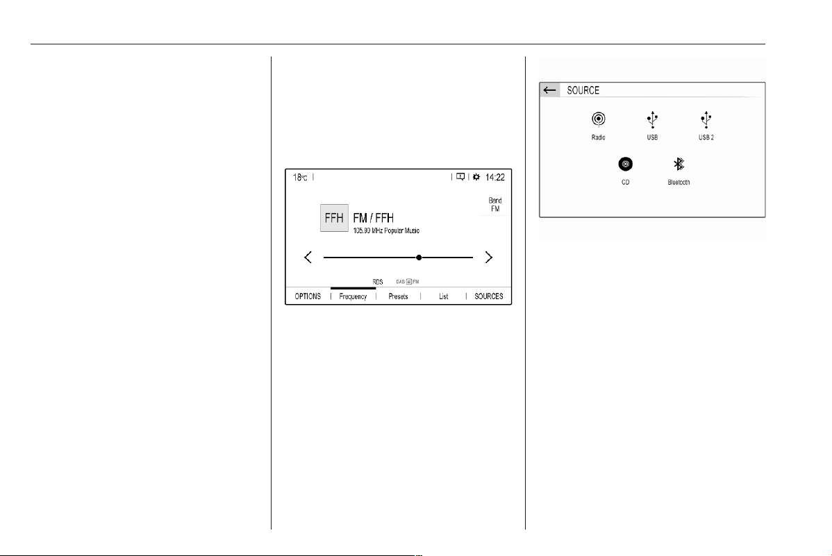
100 Infotainment system
Automatic switch-off
If the Infotainment system has been
switched on pressing ) while the
ignition is switched off, it will switch off
again automatically when the Eco
mode becomes active.
Setting the volume
Turn ). The current setting is shown
on the display.
When the Infotainment system is
switched on, the last selected volume
is set.
Speed compensated volume
When the speed compensated
volume is activated, the volume is
adapted automatically to make up for
the road and wind noise as you drive.
Mute
Press ) to mute the Infotainment
system.
To cancel the mute function,
press ) again. The last selected
volume is set again.
Modes of operation
Audio-Media
Press AUDIO / b to display the main
menu of the last selected audio mode.
Changing the media source
Select SOURCES to display the
menu for media source selection.
Select the desired media source.
For a detailed description of:
● Radio functions 3 108
● External devices 3 111
Navigation
Press NAV / c to display the
navigation map showing the area
around the current location.
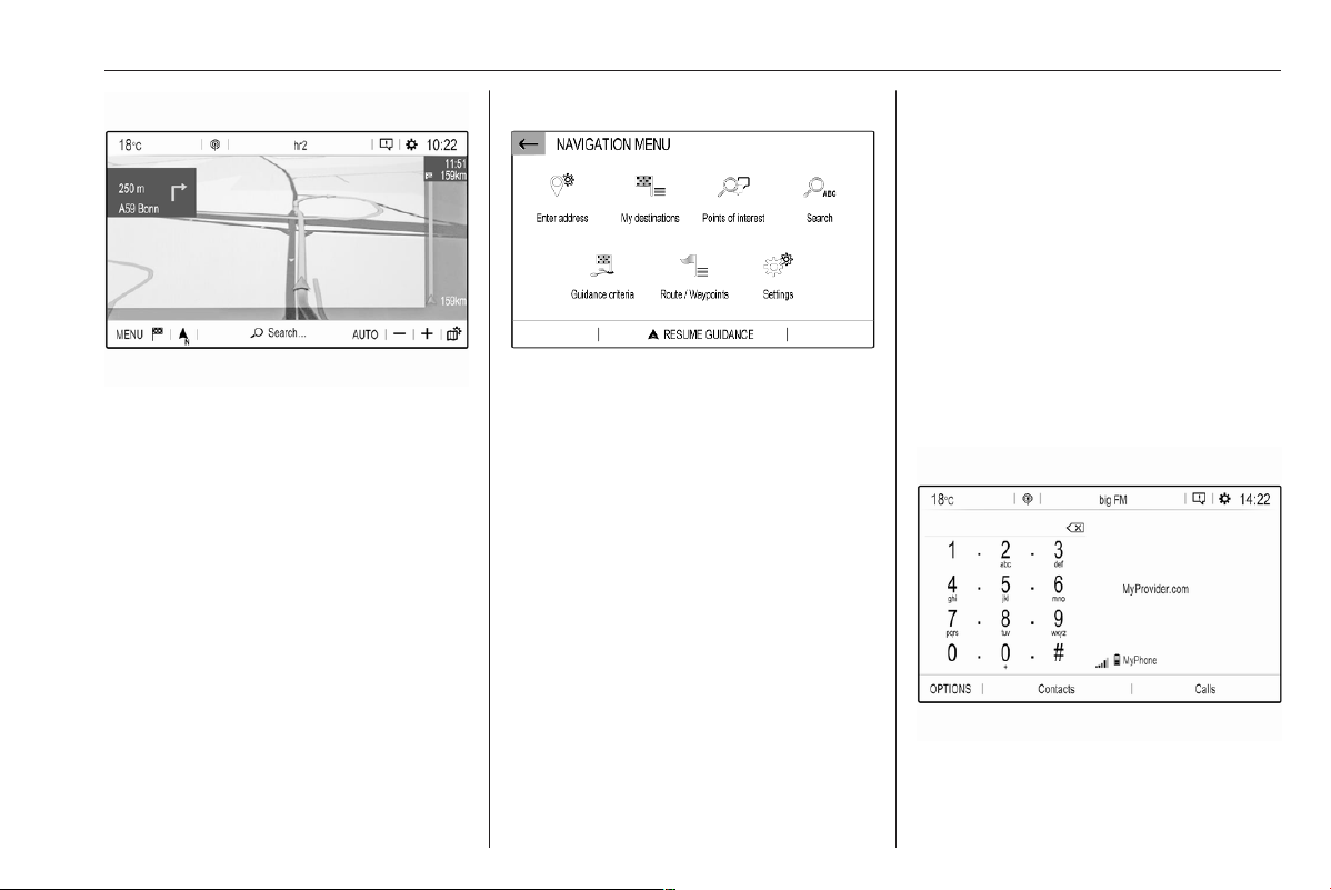
Infotainment system 101
For a detailed description of basic
functions of the navigation system
3 114.
Navigation menu
Select MENU to display the
navigation menu.
The navigation menu serves as
central entry point for:
● Address search and input
● Defining trips with several
waypoints
● Defining criteria for route
guidance
● Cancelling and resuming route
guidance
For a detailed description of basic
functions of the navigation system
3 114.
Phone
Before the phone function can be
used, a connection has to be
established between the Infotainment
system and the mobile phone.
For a detailed description of
preparing and establishing a
Bluetooth connection between the
Infotainment system and a mobile
phone 3 127.
If the mobile phone is connected,
press 6 to display the main menu of
the phone function.
For a detailed description of mobile
phone operation via the Infotainment
system 3 127.
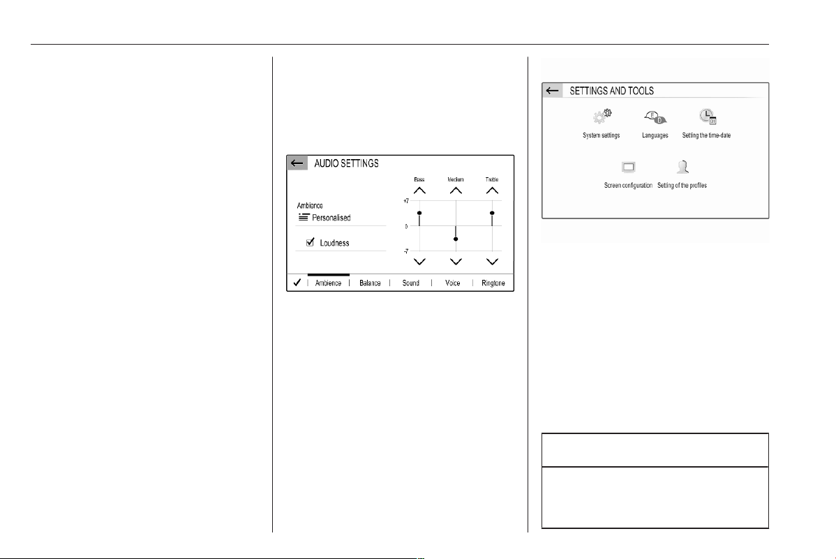
102 Infotainment system
Network and connected services
Press d and then select OPTIONS
to display the Bluetooth, network and
connected services settings.
To connect the vehicle to a Wi-Fi
network, touch y. A list of all
available Wi-Fi networks is displayed.
It is also possible to share the Wi-Fi
connection for other devices.
To update the service and connection
status, go to the menu for connected
services z and touch R.
To use the connected services, make
sure that data sharing and the vehicle
position are activated in the privacy
menu in the System settings.
Apps
To show specific apps of your
smartphone on the display of the
Infotainment system, connect your
smartphone.
Press d to display the main menu of
the apps mode.
Touch Apple CarPlay or
Android Auto. A menu with different
selectable apps is displayed.
For a detailed description 3 111.
Settings
Press SET / z and then select Audio
settings to display the respective
menu.
Press SET / z and then OPTIONS to
display a menu for various system-
related settings.
Vehicle settings
Select _ to open a menu for various
vehicle-related settings.
Vehicle personalisation 3 81.
Menu operation
The display of the Infotainment
system has a touch-sensitive surface
that allows direct interaction with the
displayed menu controls.
Caution
Do not use pointed or hard items
like ballpoint pens, pencils or
similar for touch screen operation.
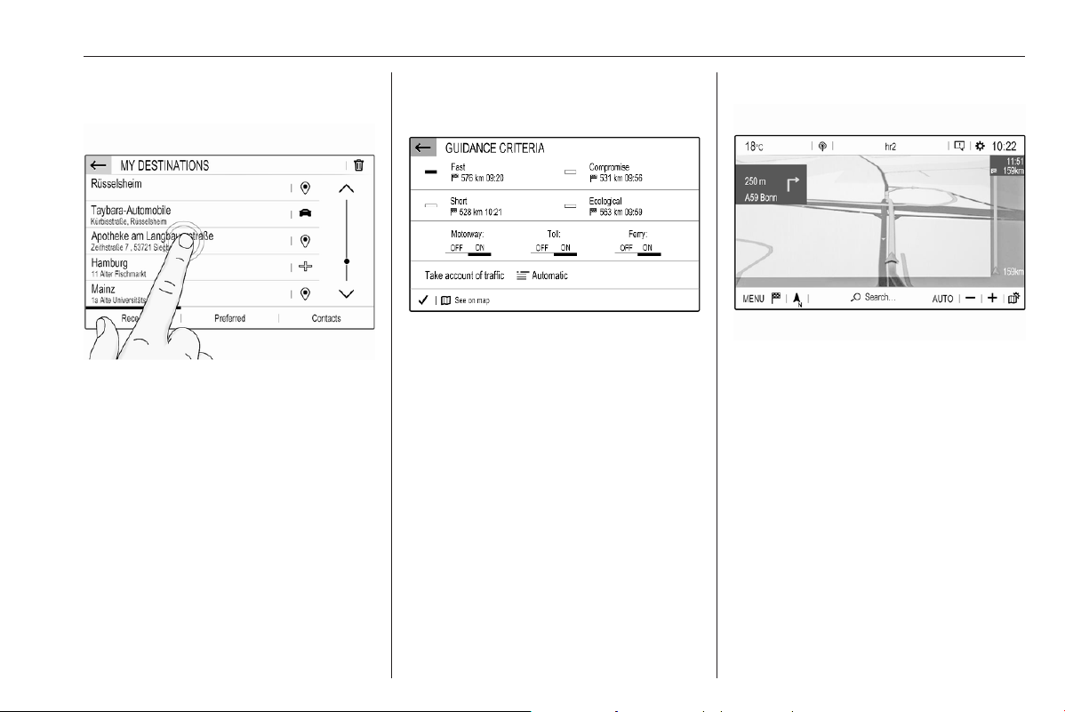
Infotainment system 103
Selecting or activating a screen
button or menu item
Touch a screen button or menu item.
Notice
Most icons displayed in a menu, like
e or d in the illustrated example,
serve as screen buttons that initiate
certain actions if you touch them.
The corresponding system function is
activated, a message is shown, or a
submenu with further options is
displayed.
3 and A / OK screen buttons
When operating the menus, touch
3 in the respective submenu to
return to the next higher menu level.
When no 3 screen button is
displayed, you are on the top level of
the respective menu.
After selecting menu items or
performing settings in a menu, touch
A / OK to confirm your settings.
Otherwise all performed selections or
settings will be lost.
Shortcuts to important menus
The texts and icons displayed in the
top bar, of e.g. the navigation main
menu, serve as shortcuts to some
important menus. For example, touch
the station name to open the station
list menu.
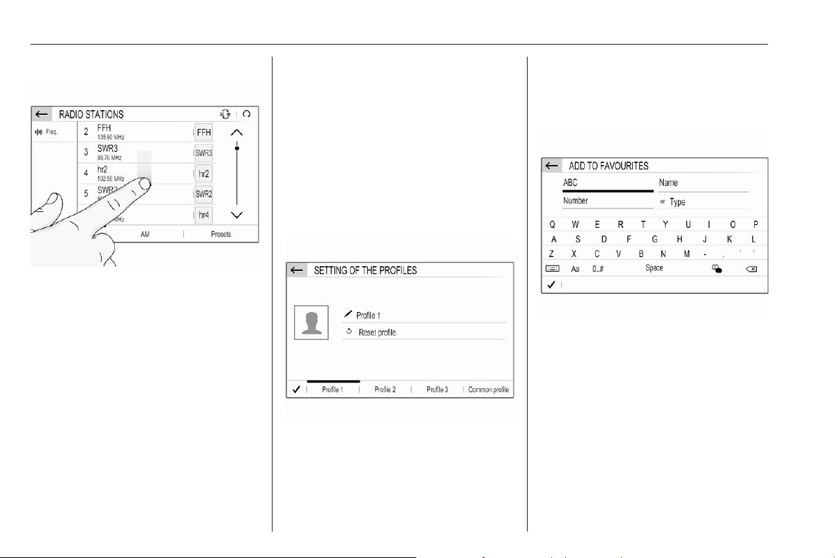
104 Infotainment system
Scrolling a list
If there are more items available than
presentable on the screen, the list
must be scrolled.
To scroll through a list of menu items,
you may optionally:
● Place your finger anywhere on
the screen and move it upwards
or downwards.
Notice
Constant pressure must be applied
and the finger must be moved at a
constant speed.
● Touch S or R at the top or
bottom of the scroll bar.
● Touch anywhere on the guiding
line of the scroll bar.
● Move the slider of the scroll bar
up and down with your finger.
Updating a list
Touch U to manually update, e.g.,
station lists, contacts lists or
destination lists.
Input fields and keyboards
Input fields are indicated by >.
Touch the input field to open a
keyboard for text or number input.
Depending on the application or
function currently active, different
keyboards are displayed.
Keyboards for text input
Keyboards for text input may contain
several input fields. To enable a field
for text input, touch it.
To enter a character, touch the
respective screen button. The
character is entered upon release.
Touch and hold a letter screen button
to display associated letters in a letter
pop-up menu. Release and then
select the desired letter.
To switch to the symbol keyboard,
touch 0..#.
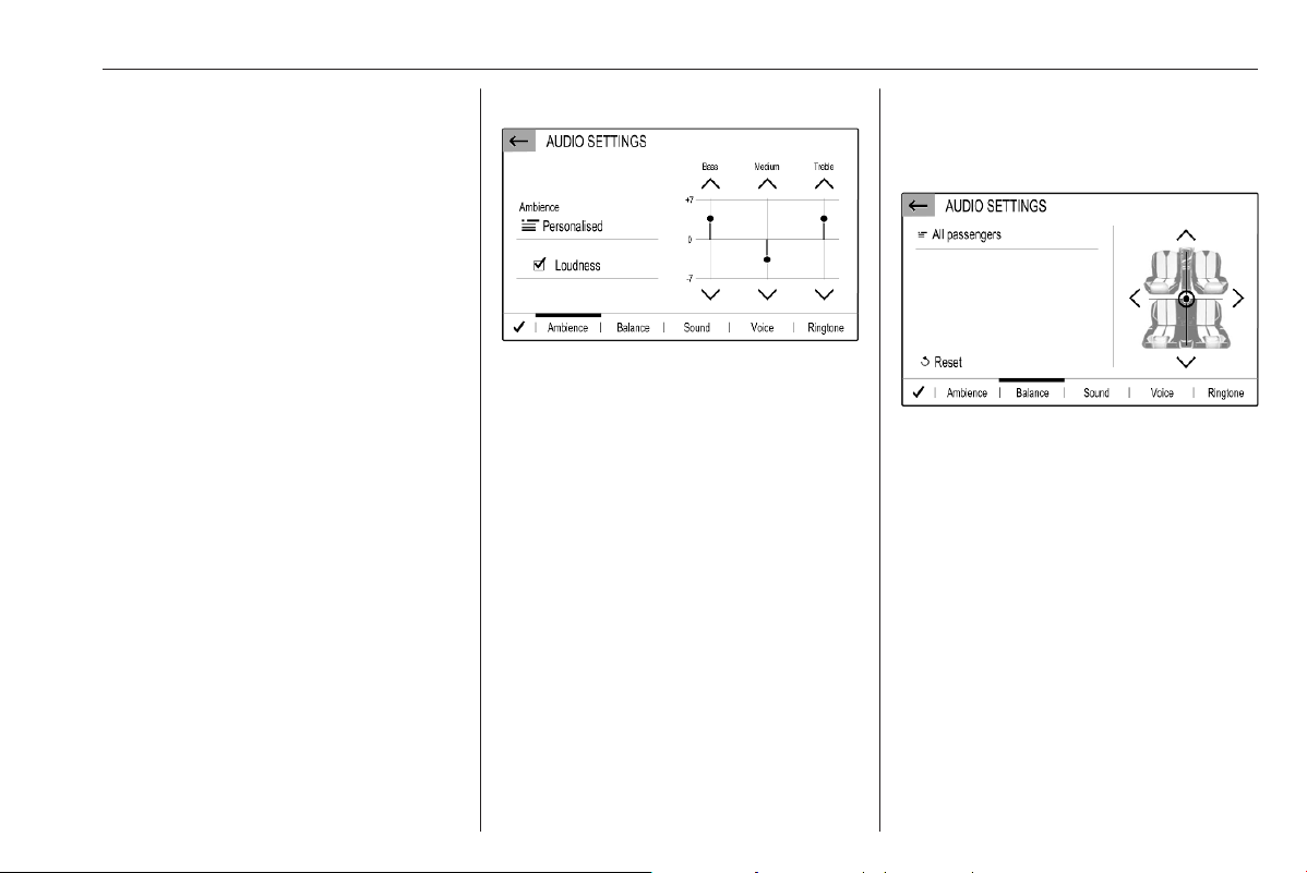
Infotainment system 105
To switch back to the letter keyboard
or to switch between capital and small
letters, touch Aa.
To switch the letter keyboard
between normal order and
alphabetical order, touch M.
To delete the most recently entered
character or symbol, touch T.
To delete a character or symbol at
any point of your input: touch at the
desired point to place a blinking
cursor, then touch T.
Audio settings
Press SET / z, select Audio
settings and then select the
Ambience tab.
Several predefined settings are
available to optimise the tone for a
specific style of music (e.g. Pop-
Rock or Classical).
To adjust the tone individually, select
User or Personalised. Change the
settings as desired and then confirm
your settings.
Notice
If you change the settings of a
predefined setting, e.g. Pop-Rock,
this settings will be applied to the
User or Personalised setting.
Activating the Loudness function may
optimise the tone at low volume
levels.
Balance and fader
Select the Balance tab.
Several predefined settings are
available to adjust the volume
distribution inside the vehicle (e.g. All
passengers or Front only).
To change the current setting, e.g. All
passengers, select that setting and
then select the desired new setting
from the displayed list.
You may individually adjust the
predefined settings.
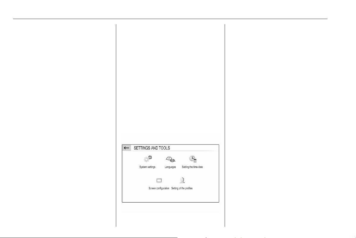
106 Infotainment system
To define the point in the passenger
compartment where the volume is at
its highest level, move the cursor in
the illustration on the right side of the
screen to the desired point.
To return to the default factory
settings, select h.
Volume settings
Press SET / z, select Audio
settings and then select the Sound
tab.
Audible touch feedback
If the audible touch feedback function
is activated, each touch of a screen
button or menu item is indicated by a
beeping sound.
To adjust the touch beep volume,
activate Touch tones and then adjust
the setting.
Speed compensated volume
Activate or deactivate Volume linked
to speed.
If activated, the volume of the
Infotainment system is adapted
automatically to make up for the road
and wind noise as you drive.
Speech output
Select the Voice tab.
Adjust the volume for all speech
outputs of the system, e.g. traffic
announcements, navigation
messages etc.
Ringtone
Select the Ringtone tab.
Adjust the ringtone volume of
incoming calls.
System settings
Press SET / z and then select
OPTIONS.
Configuring the system
Select System settings to perform
some basic system configurations,
e.g.:
● Adjust the display of units for
temperature or fuel consumption.
● Reset the system configuration to
factory defaults.
● Update the installed software
version.
● Adjust the privacy settings for
data sharing and vehicle position.
Changing display language
To adjust the language for the menu
texts, select Languages and then
select the desired language.
Notice
If the selected display language is
supported by the embedded speech
recognition, the language of the
speech recognition will be changed
accordingly; if not, embedded
speech recognition will be not
available.
Adjusting time and date
Select Setting the time-date.
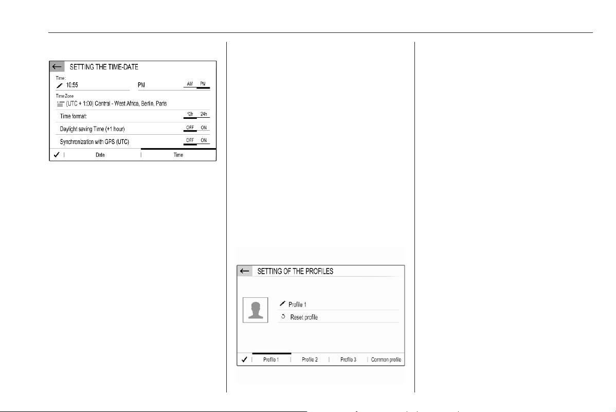
Infotainment system 107
Changing time and date formats
To change the time and date formats,
select the respective tabs and then
select the desired formats.
Setting time and date
By default the displayed time and
date is automatically adjusted by the
system.
To manually adjust the displayed time
and date:
Select the Time tab.
Set Synchronization with GPS (UTC)
to OFF and then select the Time field
to set the desired time.
Select the Date tab and then select
the Date: field to set the desired date.
Adjusting the screen
Select Screen configuration.
Text scroll function
Select the Animation tab.
If long texts on the screen should be
scrolled automatically, activate
Automatic scrolling.
If Automatic scrolling is deactivated,
long texts are truncated.
Adjusting the brightness
Select Brightness and set the
brightness of the screen to the
desired level.
Storing your personal settings
Select Setting of the profiles.
You can store a multitude of settings
in a personal profile. For example, all
current tone settings, all radio
presets, one phone book, the map
settings and your preferred
addresses.
In case you share the vehicle with
other people, this enables you to
restore your personal settings from
your profile at any time.
A maximum of three personal profiles
may be stored.
Additionally, a Common profile is
available. All settings done at any
time are automatically stored in that
profile. If no personal profile is
activated, the Common profile is
active.
Storing your personal profile
After performing all your personal
settings:
Select one of the personal profile
tabs.
Select the input field > and enter the
desired name of your personal profile.
If you want to add a photo to the
profile:
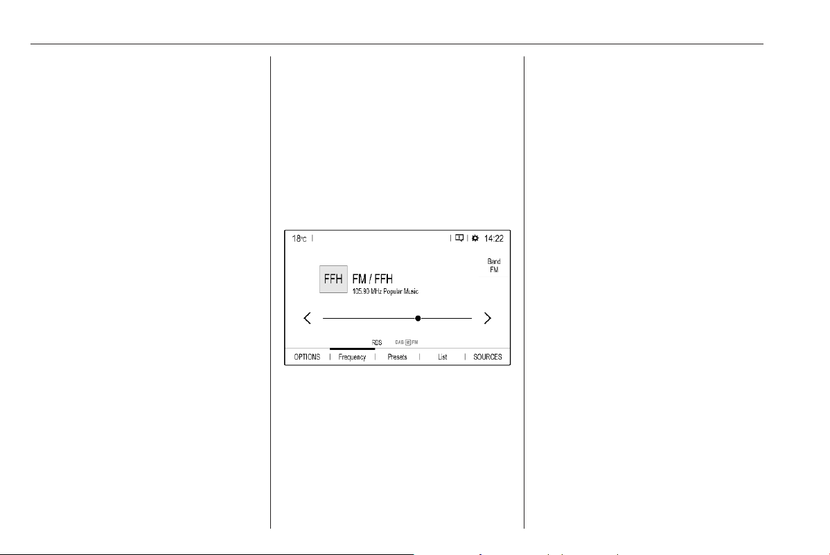
108 Infotainment system
Connect a USB device with the
desired photo stored on it to the USB
port 3 111, touch the photo frame
and then select the desired photo.
Confirm your selection to download
the selected photo to the system.
Finally, confirm your inputs to store
them in your personal profile.
Activating your personal profile
Press z and then select the tab with
the name of your personal profile.
Activating the Common profile
If a personal profile is currently active:
Press z and then select Deactivate
profile.
Resetting a personal profile
You can at any time reset a personal
profile to restore the default factory
settings on that profile.
Select the respective profile and then
select Reset profile.
Resetting the Common profile
You can at any time reset the
Common profile to restore the default
factory settings on that profile.
Select Common profile and then
select Reset the common profile.
Audio
Activating the radio
Press AUDIO / b. The audio main
menu last selected is displayed.
If the radio main menu is not active,
select SOURCES and then select
Radio.
The station last played will be
received.
Selecting a waveband
Repeatedly select Band to toggle
between the different wavebands.
Searching for stations
Automatic station search
Briefly touch P or Q to play the
previous or next receivable station.
Manual station search
Press and hold P or Q. Release when
the required frequency has almost
been reached.
A search is made for the next station
that can be received and it is played
automatically.
Station tuning
If you exactly know the reception
frequency of a radio station, you may
enter that frequency manually.
Select OPTIONS, select Radio
stations and then select the desired
waveband.
Select Freq., enter the reception
frequency and confirm your input.
If a station is receivable on that
frequency, the respective station is
played.
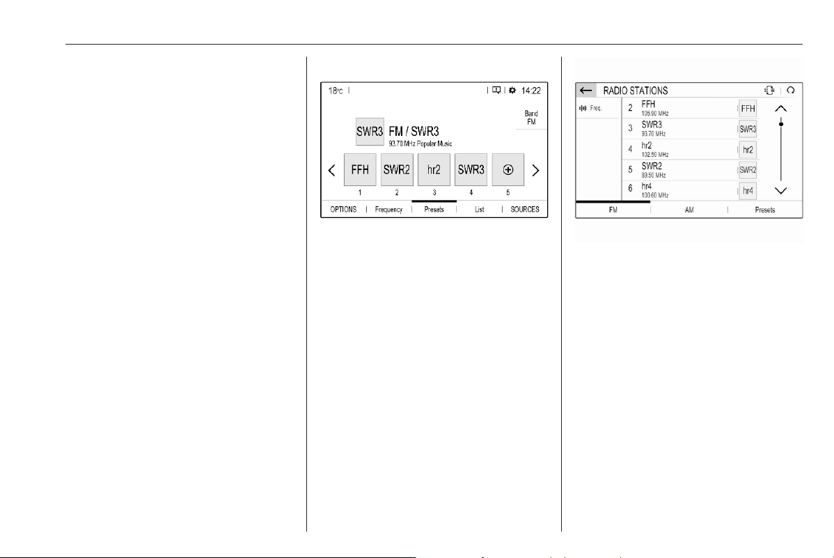
Infotainment system 109
Station lists
In the station lists, all receivable radio
stations within the current reception
area are available for selection.
To display the station list of the
waveband currently active, select
List.
Select the desired station.
Update station lists
If the stations stored in the waveband-
specific station list can no longer be
received, the AM and the DAB station
lists must be updated. The FM station
list is updated automatically.
Select OPTIONS, select Radio
stations and then select the desired
waveband.
To start an update for the selected
waveband, select U.
Storing favourite stations
Up to 15 radio stations of all
wavebands can be stored as
favourites in the Presets list.
Select Presets to display the preset
buttons.
Storing the currently active station
Touch and hold the desired button for
a few seconds. The respective
frequency or station name is
displayed on the button.
If a station is already stored on a
preset button, that station will be
overwritten by the new one.
Storing a station from a station list
Select OPTIONS, select Radio
stations and then select the desired
waveband.
Briefly touch the button next to the
desired station. Alternatively, select
7 to switch to the tiled view. Then
briefly touch a on the tile of the
desired station.
Select Add to favourites and then
touch and hold for a few seconds on
the list row where you want to store
the station.
If a station is already stored on a list
row, that station will be overwritten by
the new one.
Retrieving stations
In the radio main menu select
Presets and then briefly touch the
preset button of the desired station.

110 Infotainment system
RDS configuration
In the radio main menu select
OPTIONS and then select Radio
settings to open the menu for RDS
configuration.
Activating RDS
Select General and then activate
Alternative frequency.
If Alternative frequency is activated,
RDS is displayed in the bottom line of
the radio main menu.
Radio text
If RDS is activated, information on the
radio programme currently active or
the music track currently playing are
displayed below the programme
name.
To show or hide the information,
activate or deactivate Display radio
text.
Traffic announcements
Many RDS stations broadcast traffic
news. If the traffic announcements
function is activated, radio or media
playback is interrupted for the
duration of a traffic announcement.
Select Announcements and then
activate or deactivate Traffic
announcement.
If Traffic announcement is activated,
TA is displayed in the bottom line of
the radio main menu.
Digital audio broadcasting
Digital audio broadcasting (DAB)
broadcasts radio stations digitally.
DAB stations are indicated by the
programme name instead of the
broadcasting frequency.
DAB Announcements
Besides their music programmes, a
lot of DAB stations also broadcast
announcements of various
categories. If you activate some or all
categories, the currently received
DAB service is interrupted when an
announcement of these categories is
made.
In the radio main menu select
OPTIONS, select Radio settings and
then select Announcements.
Activate the desired announcement
categories, e.g., News or Weather.
Different announcement categories
can be selected at the same time.
FM-DAB Linking
This function enables switching from
an FM station to a corresponding
DAB station and vice versa.
Switching from FM to DAB occurs as
soon as a corresponding DAB station
is available. Therefore, it is
recommended to store favourite
stations as DAB stations to reduce
frequent switching.
Switching from DAB to FM occurs if
the signal is too weak to be picked up
by the receiver and the corresponding
FM station is available.
Notice
After switching, the volume might be
different.
Activation
Precondition is that Alternative
frequency is activated before FM-
DAB Linking can be activated.
Infotainment system 111
To activate FM-DAB Linking, go to
OPTIONS I Radio settings I
General and select FM-DAB Follow-
up.
The following symbol will be
displayed when FM-DAB Linking is
activated:
Deactivation
To deactivate FM-DAB Linking, go to
OPTIONS I Radio settings I
General and deselect FM-DAB
Follow-up.
FM-DAB Linking will automatically be
deactivated when Alternative
frequency is deactivated.
External devices
A USB port is located in the centre
console.
Caution
To protect the system, do not use
a USB hub.
Notice
The USB ports must always be kept
clean and dry.
USB ports
An MP3 player, USB device, SD card
(via USB connector / adapter) or
smartphone can be connected to the
USB port.
The Infotainment system can play
audio files or show picture files
contained in USB devices.
When connected to a USB port,
various functions of the devices
mentioned above can be operated via
the controls and menus of the
Infotainment system.
Notice
Not all auxiliary devices are
supported by the Infotainment
system.
Connecting / disconnecting a device
Connect one of the devices
mentioned above to a USB port. If
required, use the appropriate
connection cable. The music function
starts automatically.
Notice
If a non-readable USB device is
connected, a corresponding error
message appears and the
Infotainment system automatically
switches to the previous function.
To disconnect a USB device, select
another function and then remove the
USB device.
Caution
Avoid disconnecting the device
during playback. This may
damage the device or the
Infotainment system.
Bluetooth audio streaming
Streaming allows you to listen to
music from your smartphone.
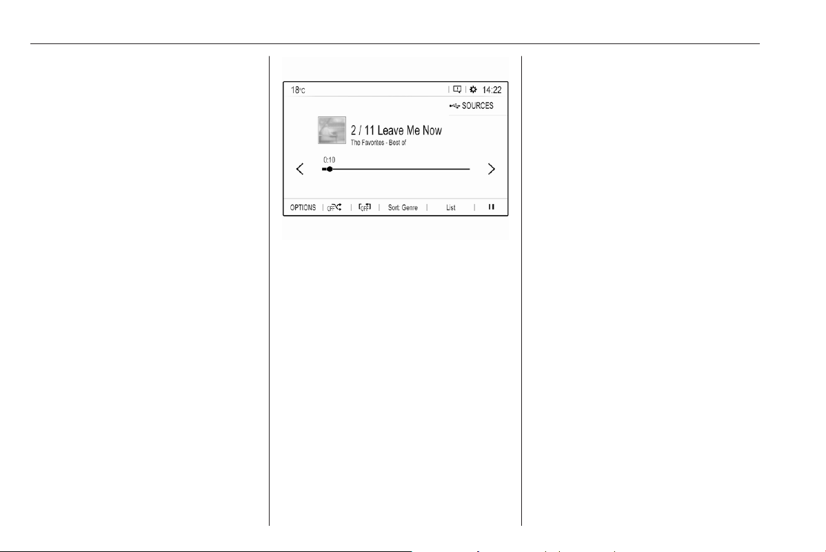
112 Infotainment system
For a detailed description on how to
establish a Bluetooth connection
3 127.
If audio playback does not start
automatically, it may be necessary to
start the playback on the smartphone.
First adjust the volume on your
smartphone (to a high level). Then
adjust the volume of Infotainment
system.
File formats
The audio equipment supports
different file formats.
Activating the music function
Connecting the USB or Bluetooth
device.
If device already connected, but
playback of stored music files not
active:
Press AUDIO / b, select SOURCES
and then select the respective
source.
Playback of the audio tracks starts
automatically.
Playback functions
Interrupting and resuming playback
Touch 5 to interrupt playback. The
screen button changes to 4.
Touch 4 to resume playback.
Playing the previous or next track
Touch P or Q.
Fast forwarding and rewinding
Touch and hold P or Q. Release to
return to normal playback mode.
Alternatively, you can move the slider
showing the current track position to
the left or right.
Playing tracks randomly
Touch button repeatedly to toggle
between the available random
modes.
j: play tracks of currently selected
list (album, artist, etc.) in random
order.
2: play all tracks stored on
connected device in random order.
k: play tracks of currently selected
list (album, artist, etc.) in normal
playback mode.
Repeating tracks
Touch button repeatedly to switch
repeat mode on or off.
n: repeat tracks of currently
selected list (album, artist, etc.).
l: play tracks of currently selected
list (album, artist, etc.) in normal
playback mode.
Browse music functions
(only available for devices connected
via USB)
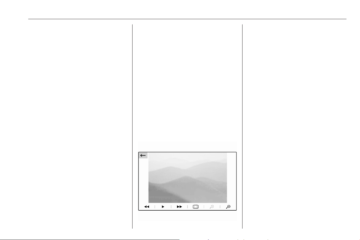
Infotainment system 113
You can have your music files sorted
according to different criteria. Two
options are available for browsing the
music files stored on the connected
USB device.
Browsing via main menu
If you want to change the currently
active USB source, select
SOURCES and then select the
desired source. The respective main
menu is displayed.
Select the button showing the
currently selected sorting criteria, e.g.
Sort: Album or Sort: Artist, and then
select the desired new sorting criteria.
A sorting process is performed.
Select List and then select the desired
track.
Playback of the selected track is
started.
Browsing via device menu
Select OPTIONS and then select
Music files.
If you want to change the currently
active USB source, select Other.
Select the desired sorting criteria, e.g.
Albums or Artists, and then select the
desired track.
Playback of the selected track is
started.
Activating the picture viewer
Connecting the USB device.
If device already connected, but
picture viewer not active:
Press AUDIO / b, select OPTIONS
and then select Managing photos.
Select the desired picture.
A slide show of all stored picture files
starts automatically.
Touch the screen to display the menu
bar.
Viewing the previous or next
picture
Touch f or g.
Starting or stopping a slide show
Select 4 to view the pictures stored
on the USB device in a slide show.
Touch 5 to end the slide show.
Phone projection
The phone projection applications
Apple CarPlay and Android Auto
display selected apps from your
smartphone on the Info Display and
allow their operation directly via the
Infotainment controls.
Check with the device's manufacturer
if this function is compatible with your
smartphone and if this application is
available in the country you are in.
Preparing the smartphone
iPhone
®
: Make sure Siri
®
is activated
on your phone.

114 Infotainment system
Android phone: Download the
Android Auto app to your phone from
the Google Play™ Store.
Connecting the smartphone
iPhone
Connect the phone to the USB port.
If the phone is already connected via
Bluetooth, upon connecting to the
USB port and launching Apple
CarPlay, the Bluetooth connection
will disconnect.
Android phone
Connect the phone via Bluetooth
3 127 and then connect the phone to
the USB port.
Starting phone projection
Press d and then touch
Apple CarPlay or Android Auto.
The phone projection screen
displayed depends on your
smartphone and software version.
Returning to the Infotainment screen
Press, e.g., the AUDIO / b button on
the control panel.
Navigation
This chapter is about the embedded
navigation system which guides to
desired destinations.
The current traffic situation is taken
into account in the route calculation.
For this purpose, the Infotainment
system receives traffic
announcements in the current
reception area via RDS-TMC.
The navigation system cannot,
however, take into account traffic
incidents, traffic regulations changed
at short notice and hazards or
problems that arise suddenly (e.g.
road works).
Caution
The usage of the navigation
system does not release the driver
from the responsibility for a
correct, vigilant attitude in road
traffic. The relevant traffic
regulations must always be
followed. If a navigation instruction
contradicts traffic regulations, the
traffic regulations always apply.
Functioning of the navigation
system
The position and movement of the
vehicle are detected by the navigation
system using sensors. The travelled
distance is determined by the
vehicle’s speedometer signal, turning
movements on bends by a sensor.
The position is determined by the
GPS (Global Positioning System)
satellites.
By comparing the sensor signals with
the digital maps, it is possible to
determine the position with an
accuracy of approx. 10 m.
The system will also work with poor
GPS reception. However, the
accuracy of the determination of the
position will be reduced.
After the entry of the destination
address or point of interest (nearest
petrol station, hotel, etc.), the route is
calculated from the current location to
the destination selected.
Route guidance is provided by voice
output and an arrow, as well as with
the aid of a multi-colour map display.

Infotainment system 115
Important information
TMC traffic information system and
dynamic route guidance
The TMC traffic information system
receives all current traffic information
from TMC radio stations. This
information is included in the
calculation of the overall route. During
this process, the route is planned so
that traffic problems related to pre-
selected criteria are avoided.
To be able to use TMC traffic
information, the system must receive
TMC stations in the relevant region.
Live navigation
When data sharing and the vehicle
position are activated, the navigation
system will show online traffic
information as well as online
information for parking, fuel prices
and weather. The services can be
stopped at anytime by deactivating
data sharing and the vehicle position.
Data sharing and the vehicle position
can be activated or deactivated via
the privacy menu in the System
settings.
Network and connected services
3 93.
The privacy menu and the menu for
connected services are also
accessible via the message icon on
the screen.
Map data
All required map data is stored within
the Infotainment system.
Map updates are available at a
Vauxhall Service Partner or at the
MyVauxhall customer portal. To
download the map updates from the
Vauxhall customer portal, a
MyVauxhall account and an empty
USB stick with at least 32 GB memory
and FAT 32 formatting are necessary.
Download and save the map data on
a computer and unpack the data onto
the USB stick.
To update the map data in the
Infotainment system, connect the
USB stick to the Infotainment system,
select the navigation function and
follow the steps on the Info Display.
The installation of the map update will
take up to 1 hour. Do not switch off the
engine during the installation
process.
Some functions of the Infotainment
system, e.g. the navigation function,
are not available during the
installation process.
Information on the map display
Press NAV / c to display the
navigation map showing the area
around the current location.
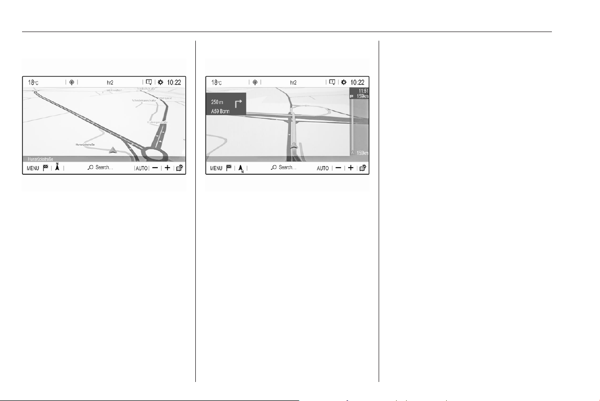
116 Infotainment system
Route guidance not active
● The map view is displayed.
● The current location is indicated
by an arrow.
● The name of the street you are
currently in is displayed at the
bottom left of the map view.
● Public charging stations are
indicated (BEV).
Propulsion types 3 4.
Route guidance active
● The map view is displayed.
● The active route is indicated by a
coloured line.
● The moving vehicle is marked by
an arrow pointing into the
direction of travel.
● The next turning manoeuvre is
shown in a separate field at the
top left of the map view.
Depending on the situation
information on lane guidance or
the second next turning
manoeuvre may be displayed
additionally.
● The arrival time and the
remaining distance to the
destination is shown at the top
right of the map view.
Customise the map display
Map views
Different map views are available.
Touch L to toggle between the
different map views.
Depending on the map view, the
remaining range is displayed as a
circle (BEV).
Propulsion types 3 4.
Map colours
Depending on the external lighting
conditions, the colouring of the map
screen (light colours for the day and
dark colours for the night) can be
adapted.
Touch ! to display a menu on the
right side of the screen.
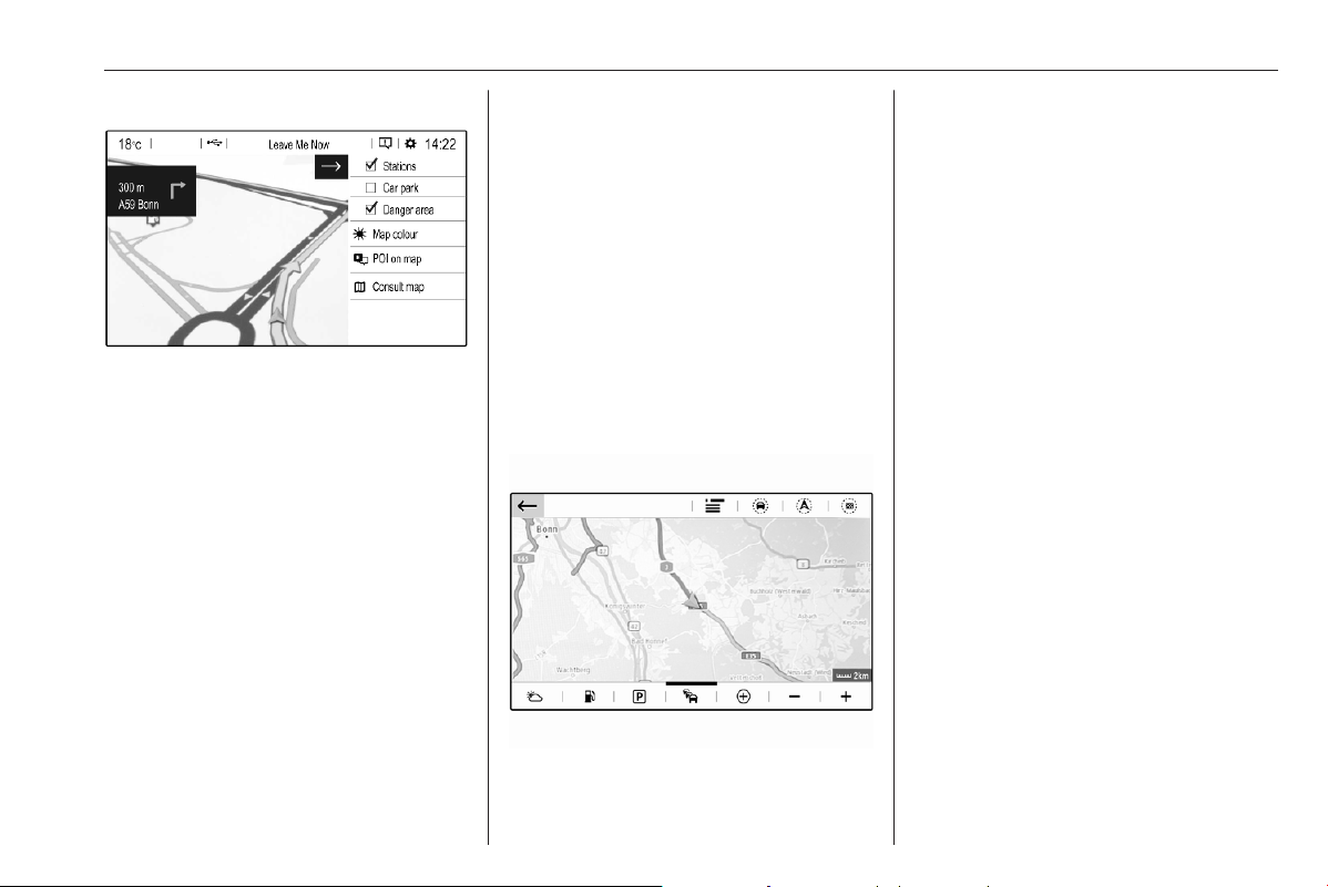
Infotainment system 117
Select Map colour repeatedly to
toggle between light and dark
colours.
POI (Points of Interest) icons on the
map
POIs are points of general interest,
e.g. petrol stations or car parks.
The display of POI categories shown
on the map may be personally
adapted.
Activate the desired POI categories.
The map view changes accordingly.
Alternatively, select POI on map to
display a menu with a multitude of
POI categories and subcategories to
choose from. Activate the desired
POI categories.
Traffic events
Traffic events may be indicated on the
map. Additionally, information on
these events may be displayed in a
list.
Select Consult map to switch to an
alternative map display with new
menu options.
The map view is switched to North
orientation mode and and may
display a greater part of the route.
Touch the traffic jam icon to show
traffic events on the map. Touch ß
to show a list with information on
these traffic events.
Touch the charging station icon to
display a circle that indicates the
remaining range (BEV).
Propulsion types 3 4.
If you want to display a different map
section:
Touch + to show the area around the
current location.
Touch , to show the entire route.
Touch . to show the area around the
destination.
To return to the default navigation
view, touch 3.
Propulsion types 3 4.
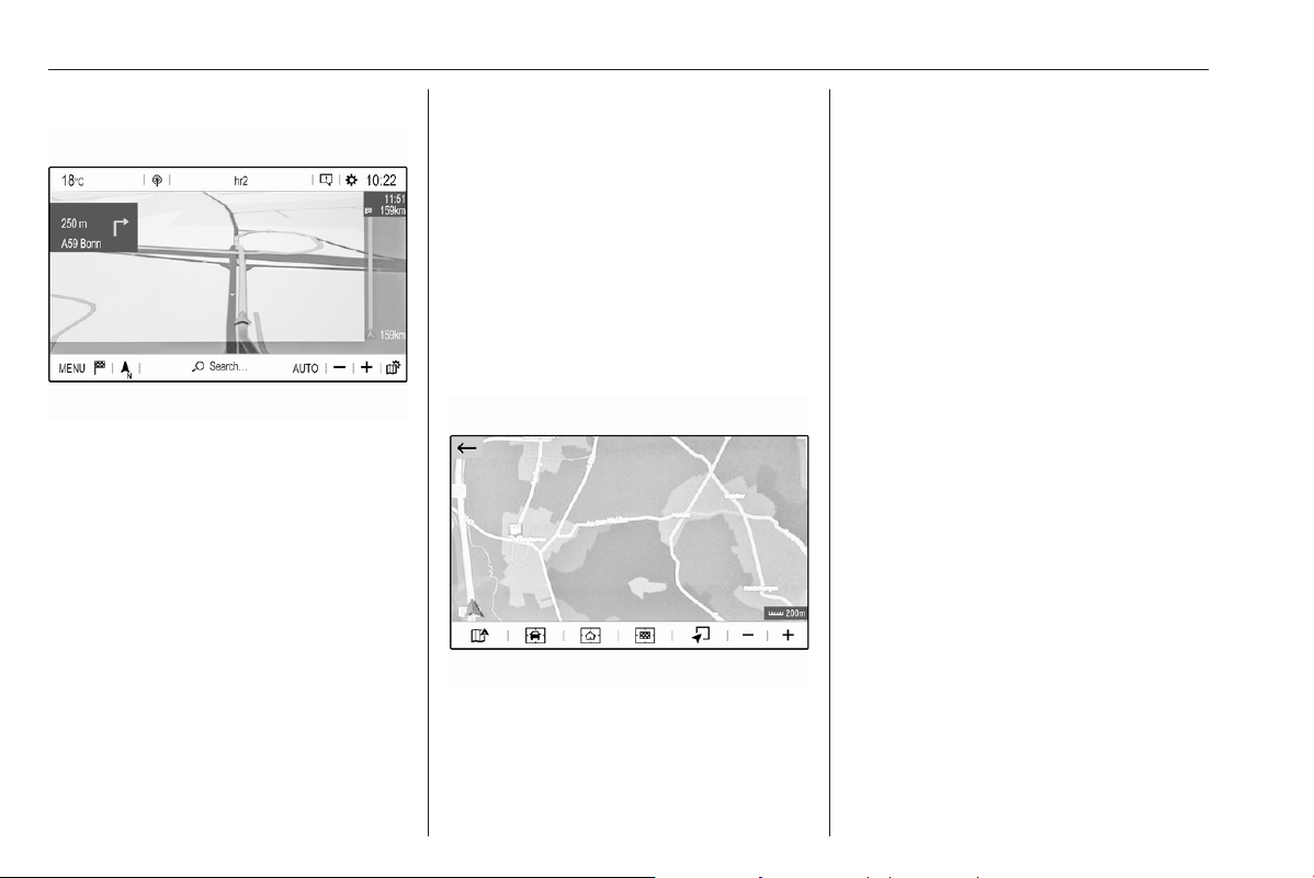
118 Infotainment system
Autozoom function
If the autozoom function is activated
(AUTO is displayed below the map
view), the zoom level changes
automatically when approaching a
turning manoeuvre during active
route guidance. This way, you always
get a good overview of the respective
manoeuvre.
If the autozoom function is
deactivated, the selected zoom level
remains the same during the whole
route guidance process.
To activate or deactivate the function:
Select MENU, select Settings and
then select the Aspect tab.
Activate or deactivate Automatic
zoom setting.
Map manipulation
Moving visible map section
Place your finger anywhere on the
screen and move it in the desired
direction.
The map moves accordingly,
displaying a new section. A new
button bar is shown.
8: show area around current
location again.
9: show area around home
address.
0: show area around destination.
To return to the default navigation
view, select 3.
Centring visible map section
Touch the desired location on the
screen to centre the map around this
location.
A red K is displayed at the respective
location and the corresponding
address is shown on a label.
Manual zooming
To zoom in on a selected map
location, place two fingers on the
screen and move them away from
each other.
Alternatively, touch + below the map
view.
To zoom out and display a larger area
around the selected location, place
two fingers on the screen and move
them towards each other.
Alternatively, touch - below the map
view.
Showing an overview of the route
Touch !, select Consult map and
then touch ,.
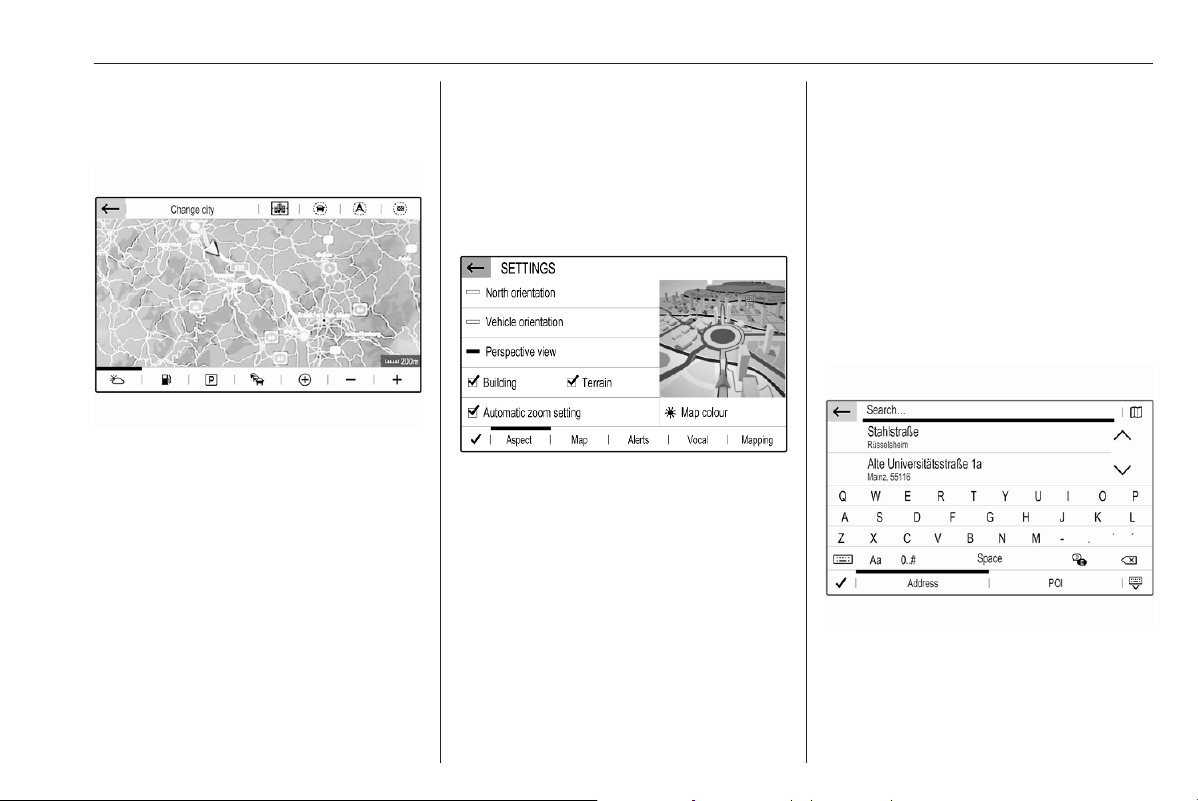
Infotainment system 119
The map view is switched to North
orientation and shows an overview of
the current route.
To return to the default navigation
view, touch 3.
Voice guidance
The route guidance process can be
supported by voice prompts given out
by the system.
To activate or deactivate the function:
Select MENU in the navigation main
menu, select Settings and then select
the Vocal tab.
Activate or deactivate Activate
navigation messages.
Navigation settings
Select MENU in the navigation main
menu, and then select Settings to
display the respective menu with a
variety of navigation related settings.
Please explore the different settings.
Some have already been described
above, others are described in the
following sections.
Selecting an address from the
map
Touch the desired location on the
map. The map centres around this
location.
A red K is displayed at the respective
location and the corresponding
address is shown on a label.
To start route guidance, select L.
For a detailed description on route
guidance.
Quick address or POI search
Select Search…. A menu with a list of
recent destinations and a keyboard is
displayed.
To refine the area for your address or
POI search, select J and then select
the desired option.
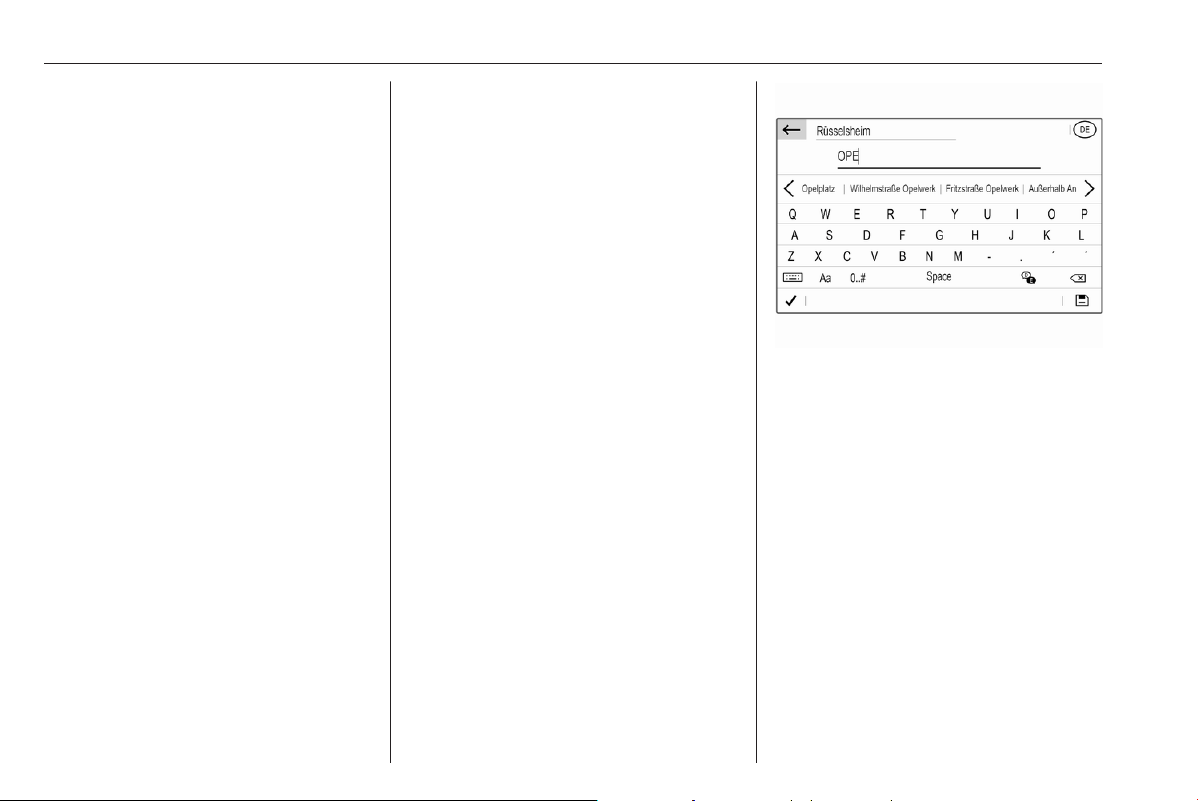
120 Infotainment system
To hide the keyboard and show the
entire list, select N. To show the
keyboard again, select O.
If you want to search for POIs (Points
of Interest) only, select the POI tab.
Enter an address or search term. As
soon as characters are entered an
address search is performed and the
list of found addresses is updated
continuously.
Select the desired list item.
Depending on the current situation
and your selection, the navigation
system may react differently:
● If the selected list item is a valid
destination address and route
guidance is currently not active:
The navigation main menu is
displayed again and route
guidance is started.
For a detailed description on
route guidance.
● If the selected list item is a valid
destination address but route
guidance is already active:
A message is displayed and you
need to decide first if the old
destination should be replaced,
or if you want to add the selected
address as an intermediate
destination to a waypoint trip.
Detailed description on waypoint
trips, see below.
Select the desired option.
● If the navigation system needs
more detailed information for
route calculation:
Enter a further search term to
refine your search.
Detailed address entry
Select MENU and then select Enter
address to display a keyboard for
address entry.
As soon as characters are entered,
an address search is started. Every
additional character is considered in
the matching process and a list of
matching addresses is displayed.
Select the desired address or change
your input to initiate a new search.
Continue with the address entry until
the entire address you are searching
for is found.
Notice
Make sure that the correct country is
selected. To change the country,
touch the country code in the upper
right corner.
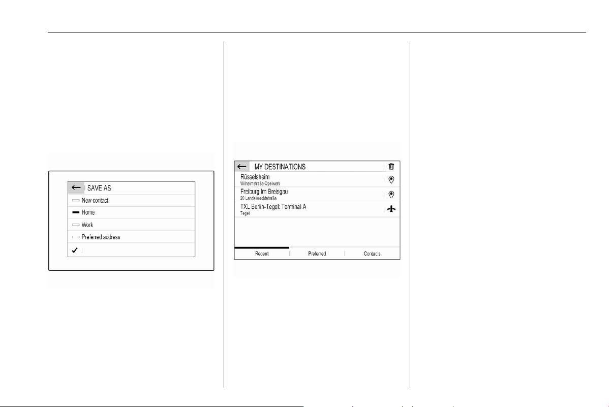
Infotainment system 121
To start route guidance to the
respective address, confirm your
input.
For a detailed description on route
guidance.
Storing your favourite addresses
If you want to store the entered
address, select 6.
You may store the address as, e.g.,
your Home address or your Work
address.
Select the desired option, confirm
your selection and then enter a name
for the address.
The stored address can then be
easily selected as destination
address via the destination lists
Preferred or Contacts, see below.
Destination lists
Select MENU and then select My
destinations.
Select Recent to display a list of all
recently entered destinations.
Select Preferred to display all
destinations which were stored
before as home address, work
address or preferred address.
Select Contacts to display a list with
contact names and all related
addresses stored before as personal
contacts.
To start route guidance to the
respective address, select a list entry.
For a detailed description on route
guidance.
Points of interest
A point of interest (POI) is a specific
location that might be of general
interest, e.g. a petrol station, a
parking area or a restaurant.
The data stored within the navigation
system contains a great number of
predefined POIs, which are indicated
on the map (if activated).
Selecting a POI from the map
Touch the desired POI icon on the
map. The map centres around this
location.
Touch the icon again.
A red K is displayed at the respective
location and the corresponding
address is shown on a label.
To start route guidance, select L.
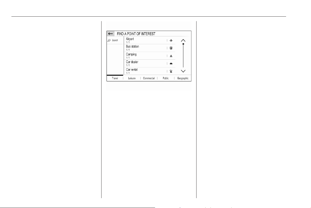
122 Infotainment system
For a detailed description on route
guidance.
Showing a list of POIs around a
location
Touch the desired location on the
map. The map centres around this
location.
A red K is displayed at the respective
location and the corresponding
address is shown on a label.
Touch and hold K.
A list of POIs around the location is
displayed.
Select the desired POI to start route
guidance.
For a detailed description on route
guidance.
Searching for POIs via categories
Select MENU and then select Points
of interest.
Select a POI main category, e.g.,
Travel and then select a subcategory,
e.g. Airport. A new menu is displayed.
Select a search area, e.g., Around the
vehicle to refine the search.
After the POI search is performed,
select the desired POI.
To search for POIs at another
location, select Address.
To search for POIs via keyword (see
below), select Search.
Searching via keyword
Select MENU, select Search, enter a
keyword, e.g., "Station", enter or
select a city name and confirm your
input.
After the POI search is performed,
select the desired POI.
Waypoint trips
A waypoint is an intermediate
destination that is considered in the
calculation of a route to its final
destination. To create a waypoint trip,
you may add one or several
waypoints.
Enter or select the final destination of
your waypoint trip and start route
guidance.
While under active route guidance,
select MENU and then select Route /
Waypoints.
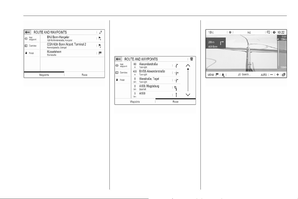
Infotainment system 123
Select Add waypoint and then select
an option for address entry, e.g. Find
POI.
Enter or select a new address. The
address is inserted into the list of
waypoints.
If desired, enter further waypoints as
described above.
If you want to change the order of the
waypoints:
Touch k and then touch the displayed
arrows to move the list entries up or
down.
Select Calculate to recalculate the
route according to the changed order.
To return to the navigation main
menu, select Finish.
To display a detailed route list of the
waypoint trip, select the Route tab.
Route guidance
Route guidance is provided by the
navigation system through visual
instructions and voice prompts (voice
guidance).
Visual instructions
Visual instructions are provided on
the display.
Notice
When route guidance is active and
you are not within the navigation
application, turning manoeuvres are
shown on the instrument cluster
display.
Voice guidance
Navigation voice prompts announce
which direction to follow, when
approaching an intersection at which
you need to turn.
To activate or deactivate the voice
prompts function select MENU in the
navigation main menu, select
Settings, select the Vocal tab and
then activate or deactivate Activate
navigation messages.
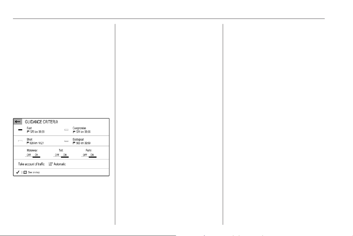
124 Infotainment system
If voice prompts are activated you can
additionally specify whether street
names should be spoken or not.
To replay the last voice guidance
instruction, touch the turn arrow on
the left side of the screen.
Settings for route guidance
Select MENU in the navigation main
menu and then select Guidance
criteria to display the respective
menu.
When the menu is opened, several
optional routes are automatically
calculated by the navigation system,
e.g. the fastest route or the most
ecological route.
To show the different optional routes
on a map, select See on map.
If you want, e.g., avoid motorways on
your route, set the respective option
to OFF.
Take account of traffic
Traffic events are taken into
consideration when the system
determines a route to a destination.
During active route guidance, the
route can be modified according to
incoming traffic messages.
Three options are available for Take
account of traffic:
If you want the system to
automatically modify the route
according to new traffic messages,
select Automatic.
If you want to be consulted when a
route is modified, select Manual.
If you do not want routes to be
modified, select None.
Starting, cancelling, resuming route
guidance
To start route guidance, enter or
select a destination address.
Depending on the situation, route
guidance may start automatically, or
you may have to follow some
instructions on the screen.
To cancel route guidance, select
MENU in the navigation main menu
and then select STOP NAVIGATION.
To resume a cancelled route
guidance, select MENU in the
navigation main menu and then
select RESUME GUIDANCE.
Turn list
The next turning manoeuvre is
displayed on the left side of the
screen.
To display a list of all upcoming turns
on the active route, select MENU in
the navigation main menu, select
Route / Waypoints and then select the
Route tab.
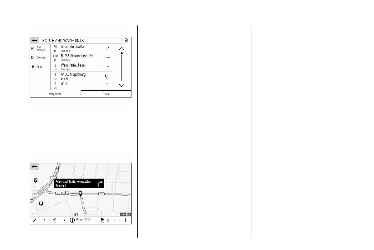
Infotainment system 125
To display a turning manoeuvre on
the map, touch the turn arrow icon
next to the desired list entry. The map
jumps to the respective location on
the map.
To display the previous or next
turning manoeuvre on the map, touch
P or Q.
To avoid the route section currently
displayed on the map, touch 6.
If desired, further route sections may
be selected to be avoided.
Confirm your selection(s).
Speech recognition
Embedded speech recognition
The embedded speech recognition of
the Infotainment system enables you
to operate various functions of the
Infotainment system via voice input. It
recognises commands and numeric
sequences independently of the
relevant speaker. The commands
and numeric sequences can be
spoken without a voice pause
between the individual words.
In the event of incorrect operation or
commands, the speech recognition
gives visual and / or acoustic
feedback and requests you to re-
enter the desired command. Apart
from this, the speech recognition
acknowledges important commands
and will enquire if necessary.
In general, there are different ways to
speak commands for performing the
desired actions.
Notice
To ensure that conversations inside
the vehicle do not lead to
unintentional triggering of the
system functions, the speech
recognition does not start until it has
been activated.
Important information
Language support
● Not all languages available for
the display of the Infotainment
system are also available for the
speech recognition.
● If the display language currently
selected is not supported by the
speech recognition, speech
recognition is not available.
In such a case, you need to select
another language for the display
if you want to control the
Infotainment system via voice

126 Infotainment system
input. To change the display
language 3 93.
Address input of destinations in
foreign countries
In case you want to enter the address
of a destination located in a foreign
country via voice input, you need to
change the language of the Info
Display to the language of the foreign
country.
E.g., if the display is currently set to
English and you want to enter the
name of a city located in France, you
need to change the display language
to French.
For changing the display language,
see "Language" in chapter "System
settings" 3 93.
Input order for destination addresses
The order in which the parts of an
address need to be entered using the
speech recognition system is
dependent on the country where the
destination is located.
If the speech recognition system
rejects your address entry, repeat the
command with a different order of the
address parts.
Activating speech recognition
Notice
Speech recognition is not available
during an active phone call.
Activation via the Y button on the
steering wheel
Press Y on the steering wheel.
The audio system mutes, a voice
output message prompts you to say a
command, and help menus with the
most important commands currently
available are shown on the display.
The speech recognition is ready for
voice input, after a beep has been
given.
You can now say a voice command to
initiate a system function (e.g. playing
a preset radio station).
Adjusting the volume of voice
prompts
Press volume button on the steering
wheel upwards (increase volume)
Y or downwards (decrease volume)
Z.
Interrupting a voice prompt
As an experienced user, you can
interrupt a voice prompt by briefly
pressing Y on the steering wheel.
Alternatively you can say "Set
dialogue mode as expert".
A beep is heard immediately, and a
command can be stated without
having to wait.
Cancelling a dialogue sequence
To cancel a dialogue sequence and
to deactivate the speech recognition,
press 6 on the steering wheel.
If you do not say any command for a
certain period of time, or if you say
commands that are not recognised by
the system, a dialogue sequence is
automatically cancelled.
Operation via speech commands
Follow the instructions given by voice
output and shown on the display.

Infotainment system 127
For best results:
● Listen for the voice prompt and
wait for the beep before saying a
command or replying.
● Read the example commands on
the display.
● The voice prompt can be
interrupted by pressing Y again.
● Wait for the beep and then speak
the command naturally, not too
fast, not too slow.
Usually commands can be spoken in
a single command.
Voice pass-thru application
The voice pass-thru application of the
Infotainment system allows access to
the speech recognition commands on
your smartphone.
Voice pass-through is available via
the phone projection applications
Apple CarPlay and Android Auto.
Activating speech recognition
Press and hold Y on the steering
wheel until a speech recognition
session is started.
Adjusting the volume of voice
prompts
Turn ) on the control panel or press
volume button on the steering wheel
upwards (increase volume) Y or
downwards (decrease volume) Z.
Deactivating speech recognition
Press 6 on the steering wheel. The
speech recognition session is ended.
Phone
The phone function provides you with
the possibility of having mobile phone
conversations via a vehicle
microphone and the vehicle
loudspeakers as well as operating the
most important mobile phone
functions via the Infotainment system
in the vehicle. To be able to use the
phone function, the mobile phone
must be connected to the
Infotainment system via Bluetooth.
Not all phone functions are supported
by every mobile phone. The usable
phone functions depend on the
relevant mobile phone and network
provider. You can find further
information on this in the operating
instructions for your mobile phone, or
you can enquire about them with your
network provider.
Important information for
operation and traffic safety
9 Warning
Mobile phones have effects on
your environment. For this reason
safety regulations and directions
have been prepared. You should
be familiar with the related
directions before you use the
telephone function.
9 Warning
Use of the hands-free facility while
driving can be dangerous because
your concentration is reduced
when telephoning. Park your

128 Infotainment system
vehicle before you use the hands-
free facility. Follow the stipulations
of the country in which you find
yourself at present.
Do not forget to follow the special
regulations that apply in specific
areas and always switch off the
mobile phone if the use of mobile
phones is prohibited, if
interference is caused by the
mobile phone or if dangerous
situations can occur.
Pairing a device
During the pairing process, PIN code
exchange between the Bluetooth
device and the Infotainment system
and connection of the Bluetooth
devices to the Infotainment system
are carried out.
Important information
● Two paired Bluetooth devices
can be connected to the
Infotainment system at the same
time. One device in hands-free
mode, the other in audio
streaming mode, see description
on Bluetooth profile settings
below.
However, two devices cannot be
used in hands-free mode at the
same time.
● Pairing only needs to be carried
out once, unless the device is
deleted from the list of paired
devices. If the device has been
connected previously, the
Infotainment system establishes
the connection automatically.
● Bluetooth operation considerably
drains the device's battery.
Therefore, connect the device to
the USB port for charging.
Pairing a new device
1. Activate the Bluetooth function of
the Bluetooth device. For further
information, see the operating
instructions for the Bluetooth
device.
2. If another Bluetooth device is
already connected:
Press 6, select OPTIONS, select
Bluetooth connection and then
touch * Search.
If no Bluetooth device is currently
connected:
Press 6 and then touch
Bluetooth search.
A search for all Bluetooth devices
in the near environment is
performed.
3. Select the Bluetooth device you
wish to pair from the displayed list.
4. Confirm the pairing procedure:
● If SSP (secure simple
pairing) is supported:
Confirm the messages on the
Infotainment system and the
Bluetooth device.
● If SSP (secure simple
pairing) is not supported:
On the Infotainment system:
a message is displayed
asking you to enter a PIN
code on your Bluetooth
device.
On the Bluetooth device:
enter the PIN code and
confirm your input.
5. Activate the functions you want
the paired smartphone to perform
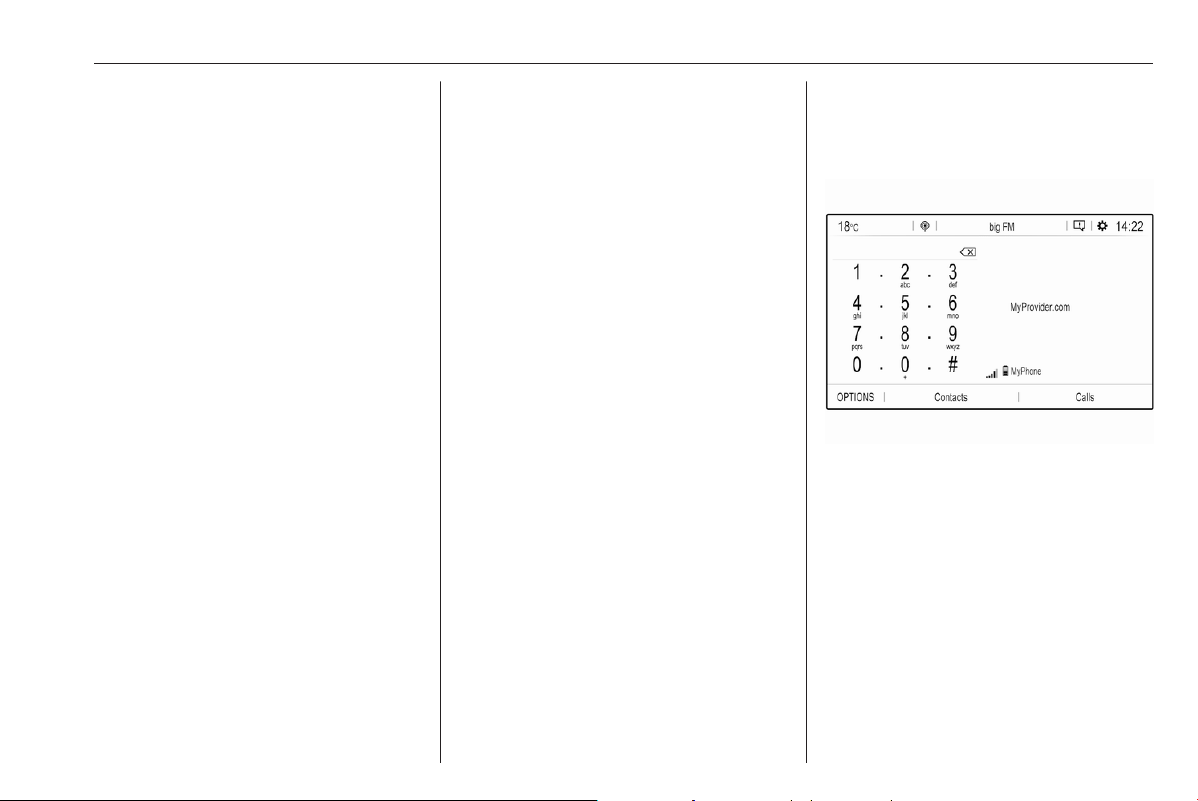
Infotainment system 129
and confirm your settings. You
can change these Bluetooth
profile settings at any time, see
below.
The Infotainment system and the
device are paired.
6. The phone book is downloaded
automatically to the Infotainment
system. Depending on the phone,
the Infotainment system must be
allowed access to the phone
book. If required, confirm the
messages displayed on the
Bluetooth device.
If this function is not supported by
the Bluetooth device, a
corresponding message is
displayed.
Operations on paired devices
Press 6, select OPTIONS and then
select Bluetooth connection.
A list of all paired devices is
displayed.
Changing the Bluetooth profile
settings
Touch a next to the desired paired
device.
Activate or deactivate the profile
settings as desired and confirm your
settings.
Connecting a paired device
Devices which are paired but not
connected are identified by X.
Select the desired device to connect
it.
Disconnecting a device
The currently connected device is
identified by W.
Select the device to disconnect it.
Deleting a paired device
Touch f in the upper right corner of
the screen to display f icons next to
each paired device.
Touch f next to the Bluetooth device
you want to delete and confirm the
displayed message.
Phone main menu
Press 6 / a to display the phone
main menu.
Many functions of the mobile phone
can now be controlled via the phone
main menu (and associated
submenus), and via the phone-
specific controls on the steering
wheel.
Initiating a phone call
Entering a phone number
Enter a phone number using the
keypad in the phone main menu.
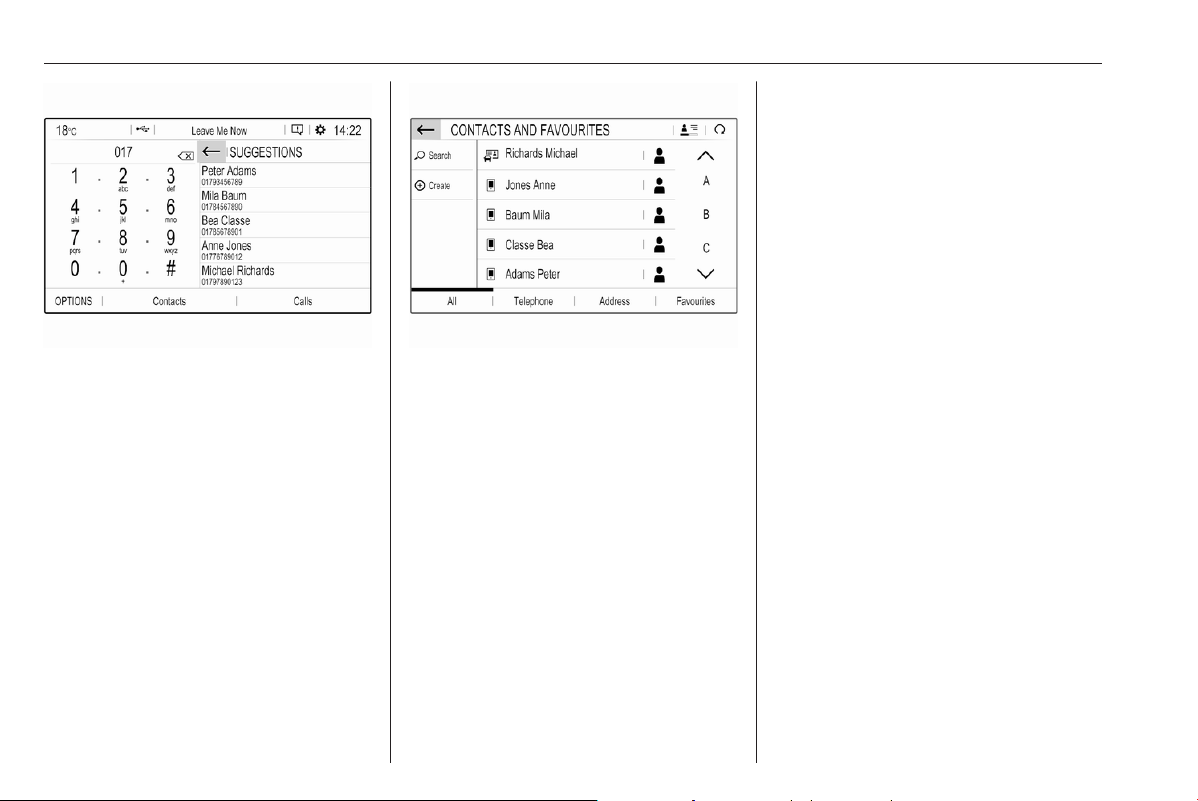
130 Infotainment system
As soon as figures are entered,
matching entries from the contacts list
are displayed in alphabetical order.
Touch the desired list entry to initiate
a phone call.
Using the contacts list
The contacts list contains all phone
book entries from the connected
Bluetooth device and all contacts
from the navigation system.
Select Contacts and then select the
desired list type.
Searching for a contact
The contacts are ordered by the first
name or surname. To change the
order, touch <.
To scroll through the list, use the
scroll bar, S or R.
To search for a contact via keyboard,
touch Search.
Modifying or deleting a contact
Select - next to the contact and then
select the desired option.
If you want to add a photo to the
contact:
Connect a USB device with the
desired photo stored on it to the USB
port 3 111, touch the photo frame and
then select the desired photo.
Confirm your selection to download
the selected photo to the system.
Using the call history
All incoming, outgoing, or missed
calls are registered.
Select Calls and then select the
desired list.
Select the desired list entry to initiate
a call.
Incoming phone call
If an audio mode, e.g. the radio or
USB mode, is active at the moment a
call comes in, the audio source is
muted and stays muted until the call
ends.
A message with the caller's phone
number or name is displayed.
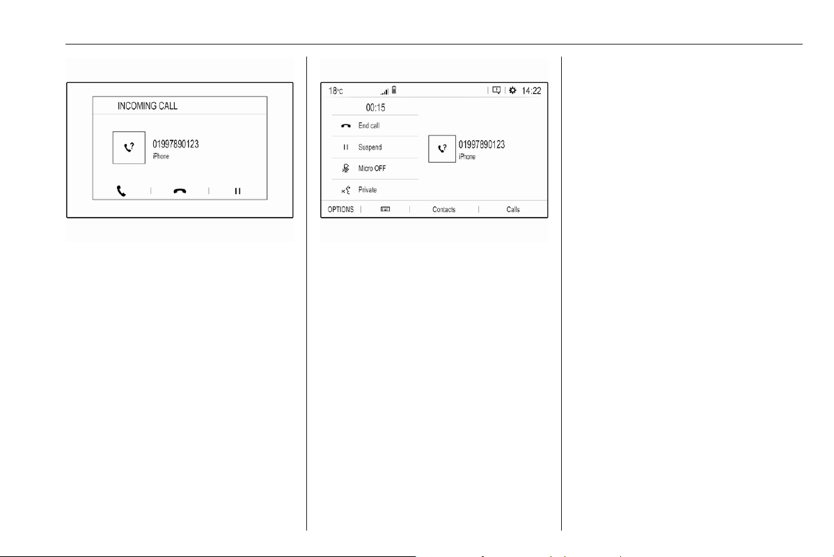
Infotainment system 131
To answer the call, touch w.
To reject the call, touch x.
To put the call on hold, touch 5. To
resume to the call, touch 4.
During the ongoing call, the following
menu is displayed.
To mute the microphone of the
Infotainment system, touch Micro
OFF.
To continue conversation via the
mobile phone (private mode), touch
l Private. To reactivate the
conversation via the Infotainment
system, touch Y Private.
Notice
If you leave the vehicle and lock it
while you are still in a private mode
phone conversation, the
Infotainment system may remain
switched on until you leave the
Bluetooth reception area of the
Infotainment system.
Put incoming calls always on hold
For safety reasons the phone function
can put all incoming calls on hold by
default.
To activate this function, select
OPTIONS, select Security and then
select Put incoming calls on hold.
Quick messages
Different quick messages can be sent
to contacts via the Infotainment
system.
Select OPTIONS and then Quick
messages to display a list of quick
messages sorted by different
categories.
To send a quick message, select the
respective message and choose the
contact.

132 Infotainment system
Multimedia
Introduction
Important information on operation
and traffic safety
9 Warning
Drive safely at all times. Only
operate the Infotainment system if
the traffic conditions allow a safe
usage.
In the interest of safety, it might be
appropriate to stop the vehicle
before operating the Infotainment
system.
9 Warning
The usage of a navigation app
does not release the driver from
the responsibility for a correct,
vigilant attitude in road traffic.
Always follow the applicable traffic
rules.
Radio reception
Radio reception may be disrupted by
static, noise, distortion or loss of
reception due to:
● changes in distance from the
transmitter
● multi-path reception due to
reflection
● shadowing
Theft-deterrent feature
The Infotainment system is equipped
with an electronic security system for
the purpose of theft deterrence.
The Infotainment system therefore
functions only in your vehicle and is
worthless to a thief.

Infotainment system 133
Multimedia
Control panel – Multimedia / Radio (Infotainment system)
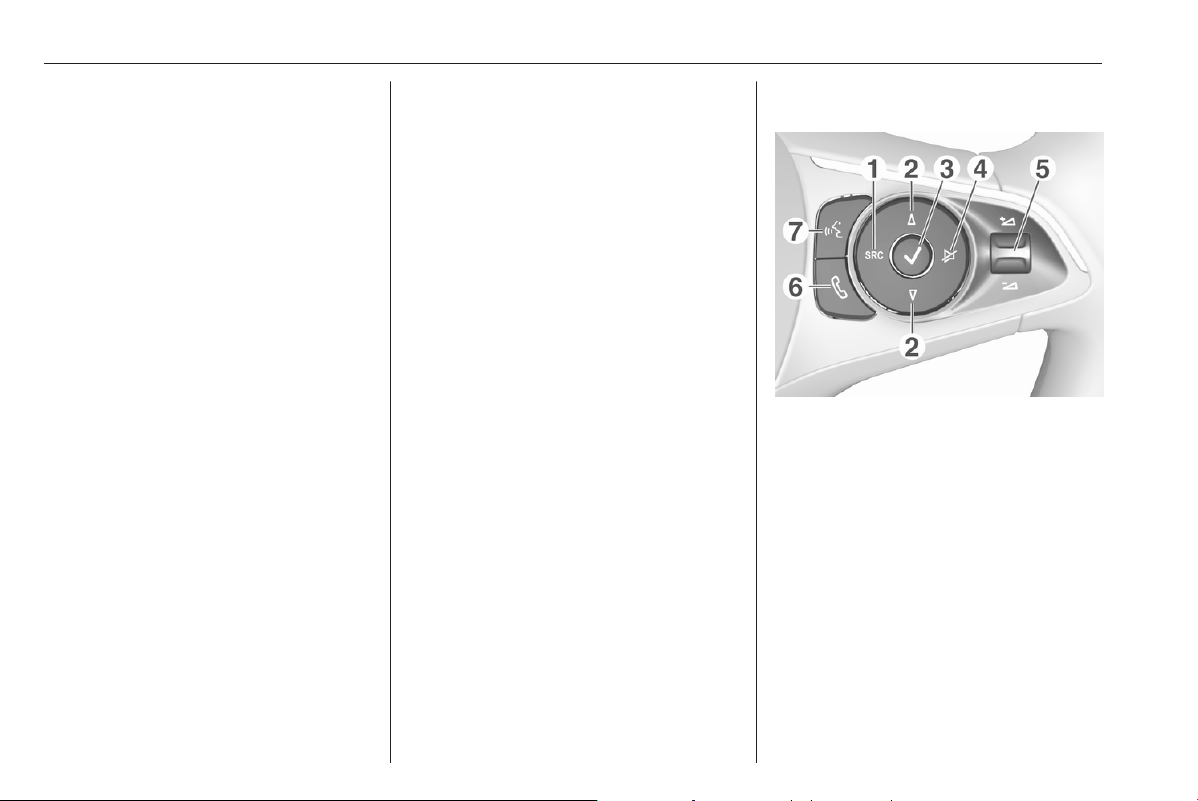
134 Infotainment system
1 )
If switched off: switch
power on / off
If switched on: mute system
Turn: adjust volume
2 Info Display
Home menu will be
displayed by a 3-finger
touch on screen
3 h
Open climate menu if available
4 c
Display navigation app
when phone projection is
active ................................... 143
5 b
Open audio menu:
Radio ................................... 141
External devices (USB,
Bluetooth) ............................ 143
6 a
Open phone menu .............. 148
Display phone projection
screen when phone
projection is active .............. 143
7 d
Open menu for picture
function ............................... 143
8 _
Open vehicle settings menu
Steering wheel controls
1 SRC (Source)
Select audio source,
confirm selection with A
Long press: mute system
2 c / d
Select next / previous
preset radio station when
radio active .......................... 141
or select next / previous
track / picture when
external devices active ....... 143

Infotainment system 135
or select next / previous
entry in station list, media
list, call / contacts list when
operation started via
steering wheel controls
Confirm selection with A
3 A
Confirm selected item
or open station list, media list
4 e
Activate / deactivate mute
function
5 Y / Z
Turn upwards /
downwards: increase /
decrease volume
6 6
Short press: accept
incoming call
Long press: reject
incoming call, hang up call .. 148
or open call / contacts list ...148
If phone call active: open
call in progress menu
7 Y
(with embedded speech
recognition)
Short press: activate
embedded speech recognition
Long press: activate
speech recognition in
Apple CarPlay™ or
Android™ Auto if phone
connected via USB port ...... 146
(without embedded
speech recognition)
Short press: activate
speech recognition in
Apple CarPlay™ or
Android™ Auto if phone
connected via USB port
Control elements
The Infotainment system is operated
via function buttons, a touch screen
and menus that are shown on the
display.
Inputs are made optionally via:
● the control panel on the
Infotainment system
● the touch screen
● audio controls on the steering
wheel
● the speech recognition 3 146
Switching the Infotainment
system on or off
Press ). After switching on, the last
selected Infotainment source
becomes active.
Notice
Some functions of the Infotainment
system are only available if ignition
is switched on or engine is running.
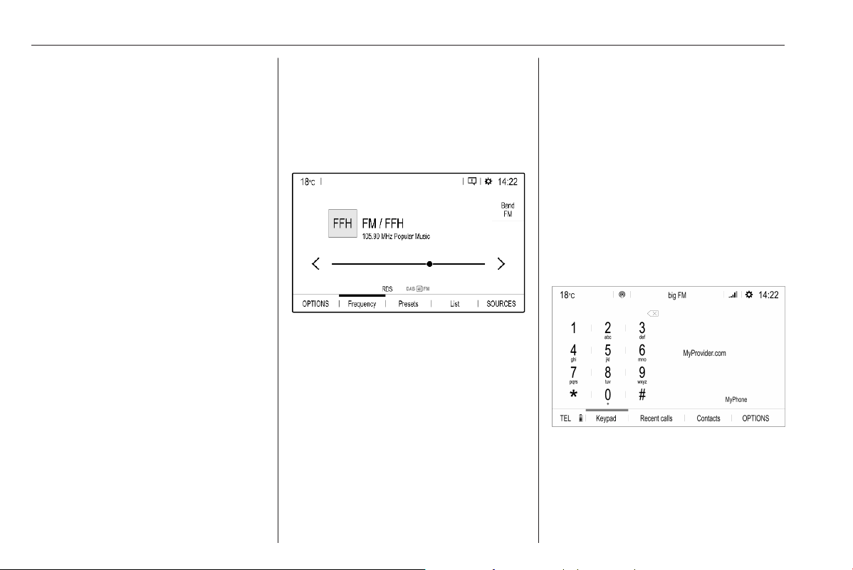
136 Infotainment system
Automatic switch-off
If the Infotainment system has been
switched on pressing ) while the
ignition is switched off, it will switch off
again automatically when the Eco
mode becomes active.
Setting the volume
Turn ). The current setting is shown
on the display.
When the Infotainment system is
switched on, the last selected volume
is set.
Speed compensated volume
When the speed compensated
volume is activated, the volume is
adapted automatically to make up for
the road and wind noise as you drive.
Mute
Press ) to mute the Infotainment
system.
To cancel the mute function,
press ) again. The last selected
volume is set again.
Modes of operation
Audio-Media
Press b to display the main menu of
the last selected audio mode.
Changing the media source
Select SOURCES to display the
menu for media source selection.
Select the desired media source.
For a detailed description of:
● Radio functions 3 141
● External devices 3 143
Phone
Before the phone function can be
used, a connection has to be
established between the Infotainment
system and the mobile phone.
For a detailed description of
preparing and establishing a
Bluetooth connection between the
Infotainment system and a mobile
phone 3 148.
If the mobile phone is connected,
press a to display the main menu of
the phone function.
For a detailed description of mobile
phone operation via the Infotainment
system 3 148.
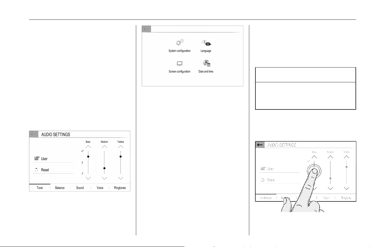
Infotainment system 137
Apps
To show specific apps of your
smartphone on the display of the
Infotainment system, connect your
smartphone.
Press a and touch Apple CarPlay or
Android Auto. A menu with different
selectable apps is displayed.
For a detailed description 3 143.
Settings
Press b, select OPTIONS and then
select Audio settings to display the
respective menu.
For a detailed description.
Touch the top bar z of the screen to
display a menu for various system-
related settings.
For a detailed description.
Vehicle settings
Select _ to open a menu for various
vehicle-related settings.
Vehicle personalisation 3 81.
Settings center
The Settings center provides quick
access to the following settings:
● dark screen
● brightness
● profiles
● system configuration
● privacy settings
Touch the top bar z of the screen to
display the Settings center.
Menu operation
The display of the Infotainment
system has a touch-sensitive surface
that allows direct interaction with the
displayed menu controls.
Caution
Do not use pointed or hard items
like ballpoint pens, pencils or
similar for touch screen operation.
Selecting or activating a screen
button or menu item
Touch a screen button or menu item.
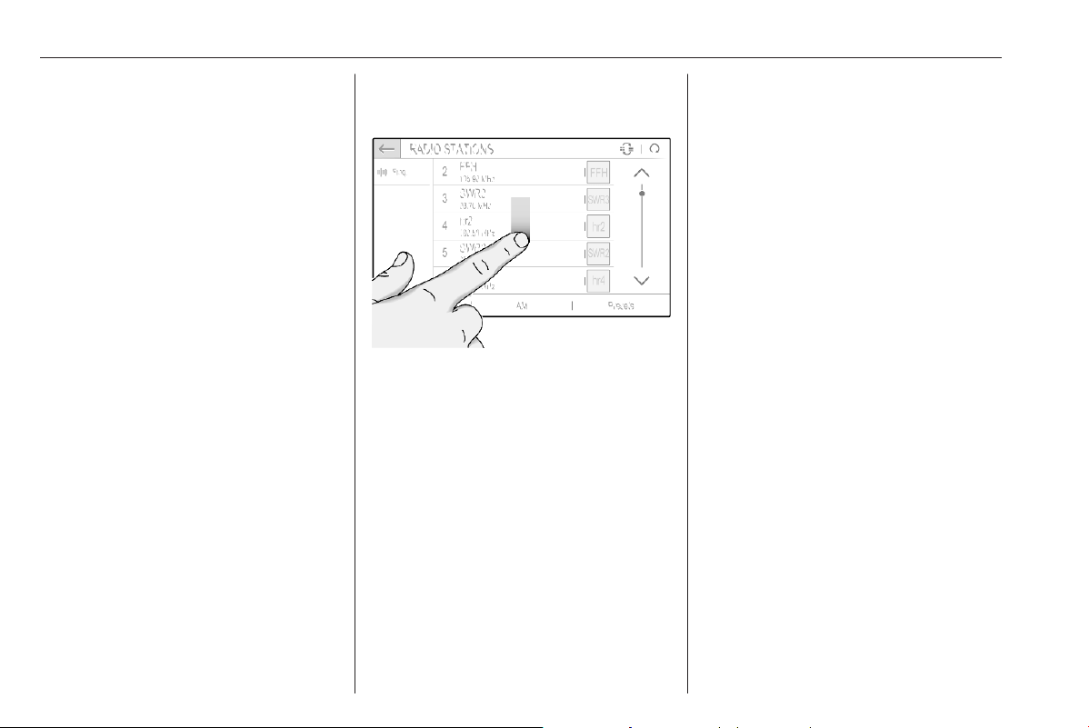
138 Infotainment system
The corresponding system function is
activated, a message is shown, or a
submenu with further options is
displayed.
3, & and A / OK screen buttons
When operating the menus, touch
3 or & in the respective submenu
to return to the next higher menu
level.
When no 3 or & screen button is
displayed, you are on the top level of
the respective menu.
On some screens A / OK needs to
be touched for confirmation after
selecting menu items or changing
settings. Otherwise all performed
selections or settings will be lost.
Scrolling a list
If there are more items available than
presentable on the screen, the list
must be scrolled.
To scroll through a list of menu items,
you may optionally:
● Place your finger anywhere on
the screen and move it upwards
or downwards.
Notice
Constant pressure must be applied
and the finger must be moved at a
constant speed.
● Touch S or R at the top or
bottom of the scroll bar.
● Touch anywhere on the guiding
line of the scroll bar.
● Move the slider of the scroll bar
up and down with your finger.
Updating a list
Touch U to manually update lists,
e.g. the station list.
Input fields and keyboards
Input fields are indicated by >.
Touch the input field to open a
keyboard for text or number input.
Depending on the application or
function currently active, different
keyboards are displayed.
Keyboards for text input
Keyboards for text input may contain
several input fields. To enable a field
for text input, touch it.
To enter a character, touch the
respective screen button. The
character is entered upon release.
Touch and hold a letter screen button
to display associated letters in a letter
pop-up menu. Release and then
select the desired letter.
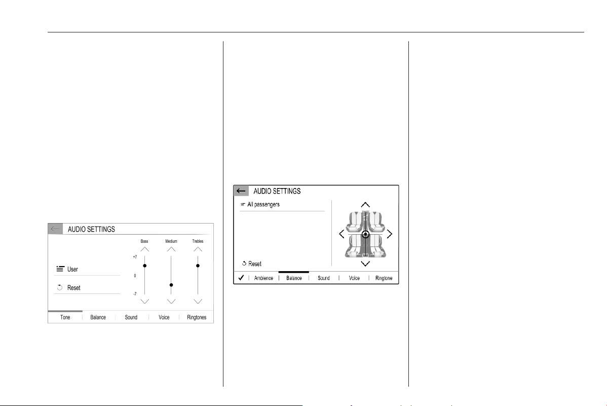
Infotainment system 139
To switch to the symbol keyboard,
touch 0..#.
To switch back to the letter keyboard
or to switch between capital and small
letters, touch Aa.
To switch the letter keyboard
between normal order and
alphabetical order, touch M.
To delete the most recently entered
character or symbol, touch T.
Audio settings
Press b, select OPTIONS and then
select AUDIO SETTINGS.
Several predefined settings are
available to optimise the tone for a
specific style of music (e.g. Pop-
Rock or Classical).
To adjust the tone individually, select
User. Change the settings as desired.
Notice
If you change the settings of a
predefined setting, e.g. Pop-Rock,
this settings will be applied to the
User or Personalised setting.
Balance and fader
Select the Balance tab.
Several predefined settings are
available to adjust the volume
distribution inside the vehicle (e.g. All
passengers or Front only).
To change the current setting, e.g. All
passengers, select that setting and
then select the desired new setting
from the displayed list.
You may individually adjust the
predefined settings.
To define the point in the passenger
compartment where the volume is at
its highest level, move the cursor in
the illustration on the right side of the
screen to the desired point.
To return to the default factory
settings, select h.
Volume settings
Press b, select OPTIONS and then
select AUDIO SETTINGS. Then
select the Sound tab.
Audible touch feedback
If the audible touch feedback function
is activated, each touch of a screen
button or menu item is indicated by a
beeping sound.
To adjust the touch beep volume,
activate Touch tones and then adjust
the setting.
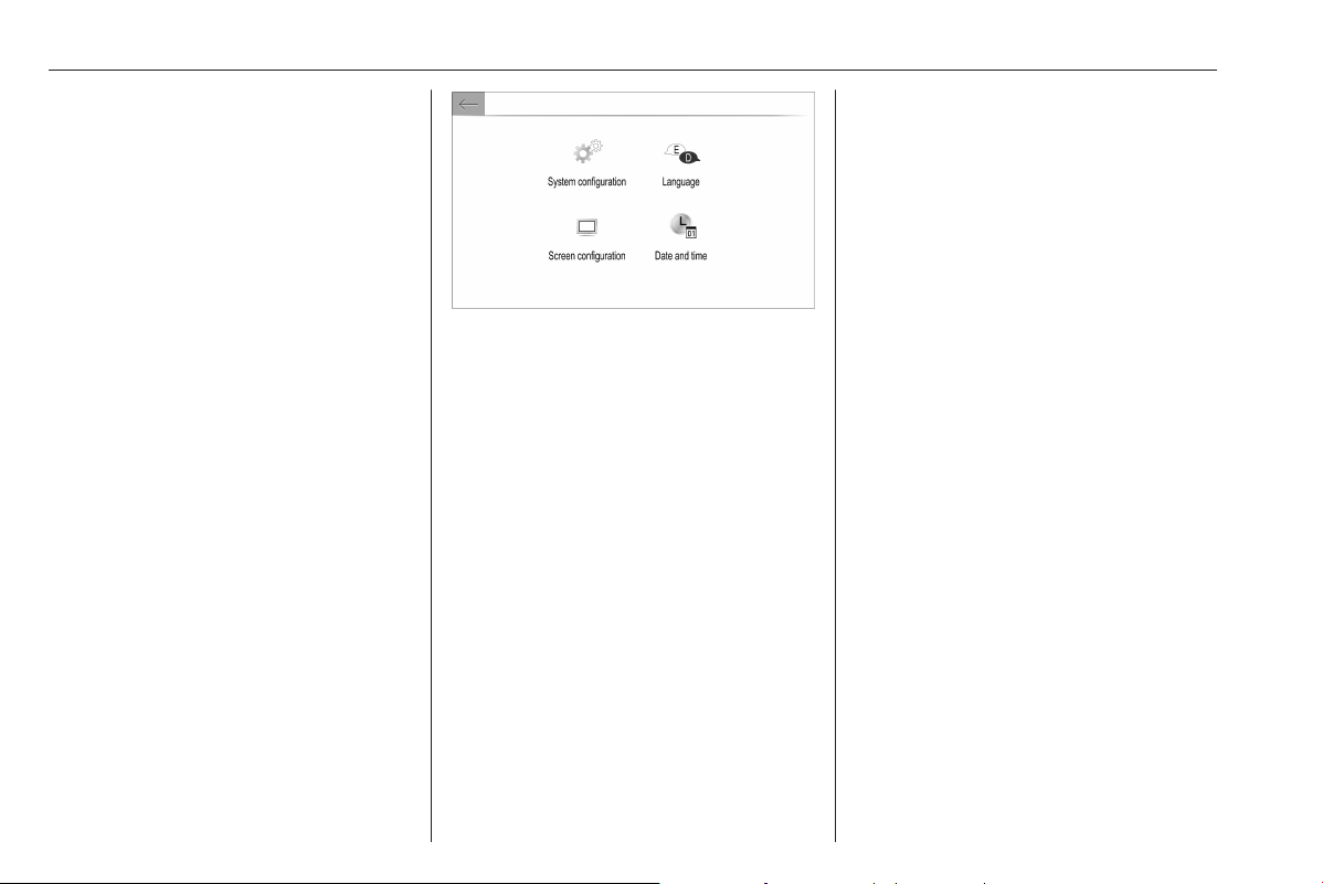
140 Infotainment system
Speed compensated volume
Activate or deactivate Volume linked
to speed.
If activated, the volume of the
Infotainment system is adapted
automatically to make up for the road
and wind noise as you drive.
Speech output
Select the Voice tab.
Adjust the volume for all speech
outputs of the system.
Ringtone
Select the Ringtones tab.
Adjust the ringtone volume of
incoming calls.
System settings
Touch the top bar z of the screen to
display the Settings center.
The configuration menu is accessible
via the Settings center.
Configuring the system
Select System configuration to
perform some basic system
configurations, e.g.:
● Adjust the display of units for
temperature or fuel consumption.
● Reset the system configuration to
factory defaults.
● Update the installed software
version.
● Adjust the privacy settings for
data sharing and vehicle position.
Changing display language
To adjust the language for the menu
texts, select Language and then
select the desired language.
Notice
If the selected display language is
supported by the embedded speech
recognition, the language of the
speech recognition will be changed
accordingly; if not, embedded
speech recognition will be not
available.
Adjusting time and date
Select Date and time.
To adjust the time and date, select the
respective tabs.
Adjusting the screen
Select Screen configuration.
Text scroll function
Select the Animation tab.
If long texts on the screen should be
scrolled automatically, activate
Automatic scrolling.
If Automatic scrolling is deactivated,
long texts are truncated.
Adjusting the brightness
Select Brightness and set the
brightness of the screen to the
desired level.
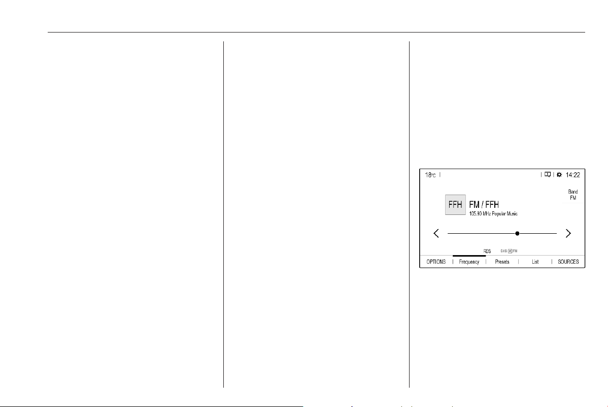
Infotainment system 141
Storing your personal settings
To go to the profile settings, touch the
top bar of the screen z and then
select Profiles.
You can store a multitude of settings
in a personal profile. For example, all
current tone settings, all radio presets
and a phone book.
In case you share the vehicle with
other people, this enables you to
restore your personal settings from
your profile at any time.
A maximum of three personal profiles
may be stored.
Additionally, a Common profile is
available. All settings done at any
time are automatically stored in that
profile. If no personal profile is
activated, the Common profile is
active.
Storing your personal profile
After performing all your personal
settings:
Select one of the personal profile
tabs.
Select the input field > and enter the
desired name of your personal profile.
Finally, confirm your inputs to store
them in your personal profile.
Activating your personal profile
Touch the top bar z of the screen,
then select Profiles and then select
the tab with the name of your personal
profile.
Activating the Common profile
If a personal profile is currently active:
Go to the Common profile tab and
then select Activate profile.
Resetting a personal profile
You can at any time reset a personal
profile to restore the default factory
settings on that profile.
Activate the respective profile and
then select Reset the profile.
Resetting the Common profile
You can at any time reset the
Common profile to restore the default
factory settings on that profile.
Select Common profile and then
select Reset the common profile.
Audio
Activating the radio
Press b. The audio main menu last
selected is displayed.
If the radio main menu is not active,
select SOURCES and then select
Radio.
The station last played will be
received.
Selecting a waveband
Select OPTIONS and repeatedly
touch i to toggle between the
different wavebands.
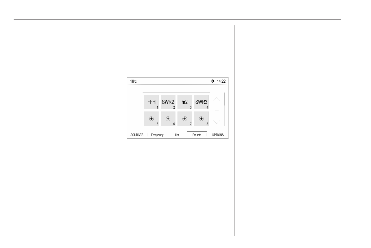
142 Infotainment system
Searching for stations
Automatic station search
Briefly touch P or Q to play the
previous or next receivable station.
Manual station search
Press and hold P or Q. Release when
the required frequency has almost
been reached.
A search is made for the next station
that can be received and it is played
automatically.
Station lists
In the station lists, all receivable radio
stations within the current reception
area are available for selection.
To display the station list of the
waveband currently active, select
List.
Select the desired station.
Update station lists
If the stations stored in the waveband-
specific station list can no longer be
received, the station lists must be
updated.
To start an update for the currently
active waveband, select U.
Storing favourite stations
Up to 24 radio stations of all
wavebands can be stored as
favourites in the Presets list.
Select Presets to display the preset
buttons.
Storing the currently active station
Touch and hold the desired button in
the Presets list for a few seconds. The
respective frequency or station name
is displayed on the button.
If a station is already stored on a
preset button, that station will be
overwritten by the new one.
Alternatively, touch ; Mem in the
radio main menu to store the currently
active station.
Storing a station from a station list
Select OPTIONS and then select the
desired waveband.
To store a station from the station list,
briefly touch ; next to the desired
station. The station is stored and the
number of the preset button will be
displayed. To delete a station,
touch ; again.
Alternatively, touch and hold the
name of the station until it is stored.
To delete the station, touch and hold
the name of the station again until a
corresponding message is displayed.
Retrieving stations
In the radio main menu select
Presets and then briefly touch the
preset button of the desired station.
Activating RDS
In the radio main menu, select
OPTIONS and activate RDS.
If RDS is activated, RDS is displayed
in the bottom line of the radio main
menu.

Infotainment system 143
Radio text
If RDS is activated, information on the
radio programme currently active or
the music track currently playing are
displayed below the programme
name.
To show or hide the information, go to
the OPTIONS menu and activate or
deactivate Information.
Traffic announcements
Many RDS stations broadcast traffic
news. If the traffic announcements
function is activated, radio or media
playback is interrupted for the
duration of a traffic announcement.
To activate traffic announcements, go
to the OPTIONS menu and activate
TA.
If TA is activated, TA is displayed in
the bottom line of the radio main
menu.
Digital audio broadcasting
Digital audio broadcasting (DAB)
broadcasts radio stations digitally.
DAB stations are indicated by the
programme name instead of the
broadcasting frequency.
FM-DAB Linking
This function enables switching from
an FM station to a corresponding
DAB station and vice versa.
Switching from FM to DAB occurs as
soon as a corresponding DAB station
is available. Therefore, it is
recommended to store favourite
stations as DAB stations to reduce
frequent switching.
Switching from DAB to FM occurs if
the signal is too weak to be picked up
by the receiver and the corresponding
FM station is available.
Notice
After switching, the volume might be
different.
Activation
Precondition is that RDS is activated
before FM-DAB Linking can be
activated.
To activate FM-DAB Linking, select
OPTIONS in the radio main menu and
then select FM-DAB Follow-up.
The following symbol will be
displayed when FM-DAB Linking is
activated:
Deactivation
To deactivate FM-DAB Linking, select
OPTIONS in the radio main menu and
then deselect FM-DAB Follow-up.
FM-DAB Linking will automatically be
deactivated when RDS is
deactivated.
External devices
A USB port is located in the centre
console.
Caution
To protect the system, do not use
a USB hub.
Notice
The USB ports must always be kept
clean and dry.

144 Infotainment system
USB ports
An MP3 player, USB device, SD card
(via USB connector / adapter) or
smartphone can be connected to the
USB port.
The Infotainment system can play
audio files or show picture files
contained in USB devices.
When connected to a USB port,
various functions of the devices
mentioned above can be operated via
the controls and menus of the
Infotainment system.
Notice
Not all auxiliary devices are
supported by the Infotainment
system.
Connecting / disconnecting a device
Connect one of the devices
mentioned above to a USB port. If
required, use the appropriate
connection cable. The music function
starts automatically.
Notice
If a non-readable USB device is
connected, a corresponding error
message appears and the
Infotainment system automatically
switches to the previous function.
To disconnect a USB device, select
another function and then remove the
USB device.
Caution
Avoid disconnecting the device
during playback. This may
damage the device or the
Infotainment system.
Bluetooth audio streaming
Streaming allows you to listen to
music from your smartphone.
For a detailed description on how to
establish a Bluetooth connection
3 148.
If audio playback does not start
automatically, it may be necessary to
start the playback on the smartphone.
First adjust the volume on your
smartphone (to a high level). Then
adjust the volume of Infotainment
system.
File formats
The audio equipment supports
different file formats.
Activating the music function
Connecting the USB or Bluetooth
device.
If device already connected, but
playback of stored music files not
active:
Press b, select SOURCES and then
select the respective source.
Playback of the audio tracks starts
automatically.
Playback functions
Interrupting and resuming playback
Touch 5 to interrupt playback. The
screen button changes to 4.
Touch 4 to resume playback.
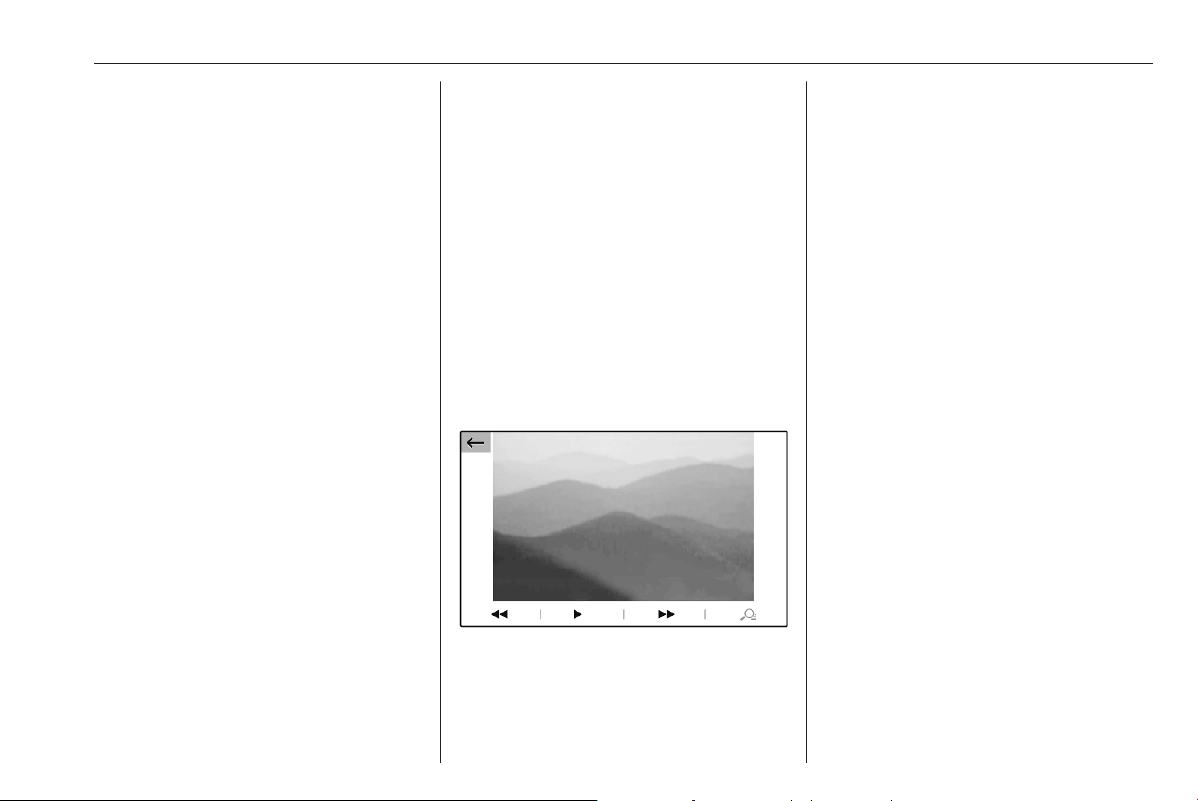
Infotainment system 145
Playing the previous or next track
Touch P or Q.
Fast forwarding and rewinding
Touch and hold P or Q. Release to
return to normal playback mode.
Alternatively, you can move the slider
showing the current track position to
the left or right.
Playing tracks randomly
Select OPTIONS and touch the
Random icon repeatedly:
j: play tracks of currently selected
list (album, artist, etc.) in random
order.
2: play all tracks stored on
connected device in random order.
k: play tracks of currently selected
list (album, artist, etc.) in normal
playback mode.
Repeating tracks
Select OPTIONS and touch the
Repeat icon n repeatedly to select
one of the following options:
n: repeat tracks of currently
selected list (album, artist, etc.)
m: repeat tracks of currently
selected list (album, artist, etc.) once
l: play tracks of currently selected
list (album, artist, etc.) in normal
playback mode
Activating the picture viewer
Connecting the USB device.
If device already connected, but
picture viewer not active:
Press d, select Photos and choose
the desired folder and picture.
Touch the screen to display the menu
bar.
Viewing the previous or next
picture
Touch f or g.
Starting or stopping a slide show
Select 4 to view the pictures stored
on the USB device in a slide show.
Touch 5 to end the slide show.
Phone projection
The phone projection applications
Apple CarPlay and Android Auto
display selected apps from your
smartphone on the Info Display and
allow their operation directly via the
Infotainment controls.
Check with the device's manufacturer
if this function is compatible with your
smartphone and if this application is
available in the country you are in.
Preparing the smartphone
iPhone
®
: Make sure Siri
®
is activated
on your phone.
Android phone: Download the
Android Auto app to your phone from
the Google Play™ Store.

146 Infotainment system
Connecting the smartphone
iPhone
Connect the phone to the USB port.
If the phone is already connected via
Bluetooth, upon connecting to the
USB port and launching Apple
CarPlay, the Bluetooth connection
will disconnect. After disconnecting
the USB connection, the phone will be
connected via Bluetooth again.
Android phone
Connect the phone via Bluetooth
3 148 and then connect the phone to
the USB port.
Starting phone projection
If phone projection is not starting
automatically, press a and then
touch Apple CarPlay or
Android Auto.
The phone projection screen
displayed depends on your
smartphone and software version.
Returning to the Infotainment screen
Press, e.g., the b button on the
control panel.
Speech recognition
Embedded speech recognition
The embedded speech recognition of
the Infotainment system enables you
to operate various functions of the
Infotainment system via voice input. It
recognises commands and numeric
sequences independently of the
relevant speaker. The commands
and numeric sequences can be
spoken without a voice pause
between the individual words.
In the event of incorrect operation or
commands, the speech recognition
gives visual and / or acoustic
feedback and requests you to re-
enter the desired command. Apart
from this, the speech recognition
acknowledges important commands
and will enquire if necessary.
In general, there are different ways to
speak commands for performing the
desired actions.
Notice
To ensure that conversations inside
the vehicle do not lead to
unintentional triggering of the
system functions, the speech
recognition does not start until it has
been activated.
Important information
Language support
● Not all languages available for
the display of the Infotainment
system are also available for the
speech recognition.
● If the display language currently
selected is not supported by the
speech recognition, speech
recognition is not available.
In such a case, you need to select
another language for the display
if you want to control the
Infotainment system via voice
input. To change the display
language 3 132.
Activating speech recognition
Notice
Speech recognition is not available
during an active phone call.
Activation via the Y button on the
steering wheel
Press Y on the steering wheel.

Infotainment system 147
The audio system mutes, a voice
output message prompts you to say a
command, and help menus with the
most important commands currently
available are shown on the display.
The speech recognition is ready for
voice input, after a beep has been
given.
You can now say a voice command to
initiate a system function (e.g. playing
a preset radio station).
Adjusting the volume of voice
prompts
Press volume button on the steering
wheel upwards (increase volume)
Y or downwards (decrease volume)
Z.
Interrupting a voice prompt
As an experienced user, you can
interrupt a voice prompt by briefly
pressing Y on the steering wheel.
Alternatively you can say "Set
dialogue mode as expert".
A beep is heard immediately, and a
command can be stated without
having to wait.
Cancelling a dialogue sequence
To cancel a dialogue sequence and
to deactivate the speech recognition,
press 6 on the steering wheel.
If you do not say any command for a
certain period of time, or if you say
commands that are not recognised by
the system, a dialogue sequence is
automatically cancelled.
Operation via speech commands
Follow the instructions given by voice
output and shown on the display.
For best results:
● Listen for the voice prompt and
wait for the beep before saying a
command or replying.
● Read the example commands on
the display.
● The voice prompt can be
interrupted by pressing Y again.
● Wait for the beep and then speak
the command naturally, not too
fast, not too slow.
Usually commands can be spoken in
a single command.
Voice pass-thru application
The voice pass-thru application of the
Infotainment system allows access to
the speech recognition commands on
your smartphone.
Voice pass-through is available via
the phone projection applications
Apple CarPlay and Android Auto.
Activating speech recognition
Press (without embedded speech
recognition) or press and hold (with
embedded speech recognition) Y on
the steering wheel until a speech
recognition session is started.
Adjusting the volume of voice
prompts
Turn ) on the control panel or press
volume button on the steering wheel
upwards (increase volume) Y or
downwards (decrease volume) Z.
Deactivating speech recognition
Press 6 on the steering wheel. The
speech recognition session is ended.

148 Infotainment system
Phone
The phone function provides you with
the possibility of having mobile phone
conversations via a vehicle
microphone and the vehicle
loudspeakers as well as operating the
most important mobile phone
functions via the Infotainment system
in the vehicle. To be able to use the
phone function, the mobile phone
must be connected to the
Infotainment system via Bluetooth.
Not all phone functions are supported
by every mobile phone. The usable
phone functions depend on the
relevant mobile phone and network
provider. You can find further
information on this in the operating
instructions for your mobile phone, or
you can enquire about them with your
network provider.
Important information for
operation and traffic safety
9 Warning
Mobile phones have effects on
your environment. For this reason
safety regulations and directions
have been prepared. You should
be familiar with the related
directions before you use the
telephone function.
9 Warning
Use of the hands-free facility while
driving can be dangerous because
your concentration is reduced
when telephoning. Park your
vehicle before you use the hands-
free facility. Follow the stipulations
of the country in which you find
yourself at present.
Do not forget to follow the special
regulations that apply in specific
areas and always switch off the
mobile phone if the use of mobile
phones is prohibited, if
interference is caused by the
mobile phone or if dangerous
situations can occur.
Pairing a device
During the pairing process, PIN code
exchange between the Bluetooth
device and the Infotainment system
and connection of the Bluetooth
devices to the Infotainment system
are carried out.
Important information
● Two paired Bluetooth devices
can be connected to the
Infotainment system at the same
time. One device in hands-free
mode, the other in audio
streaming mode, see description
on Bluetooth profile settings
below.
However, two devices cannot be
used in hands-free mode at the
same time.
● Pairing only needs to be carried
out once, unless the device is
deleted from the list of paired
devices. If the device has been

Infotainment system 149
connected previously, the
Infotainment system establishes
the connection automatically.
● Bluetooth operation considerably
drains the device's battery.
Therefore, connect the device to
the USB port for charging.
Pairing a new device
1. Activate the Bluetooth function of
the Bluetooth device. For further
information, see the operating
instructions for the Bluetooth
device.
2. Press a and then touch Bluetooth
search.
A search for all Bluetooth devices
in the near environment is
performed.
3. Select the Bluetooth device you
wish to pair from the displayed list.
4. Confirm the pairing procedure:
● If SSP (secure simple
pairing) is supported:
Confirm the messages on the
Infotainment system and the
Bluetooth device.
● If SSP (secure simple
pairing) is not supported:
On the Infotainment system:
a message is displayed
asking you to enter a PIN
code on your Bluetooth
device.
On the Bluetooth device:
enter the PIN code and
confirm your input.
The Infotainment system and
the device are paired.
5. The phone book is downloaded
automatically to the Infotainment
system. Depending on the phone,
the Infotainment system must be
allowed access to the phone
book. If required, confirm the
messages displayed on the
Bluetooth device.
If this function is not supported by
the Bluetooth device, a
corresponding message is
displayed.
Operations on paired devices
Press a, select TEL and then select
Bluetooth connection.
A list of all paired devices is
displayed.
Changing the Bluetooth profile
settings
Touch % next to the desired paired
device.
Activate or deactivate the profile
settings as desired and confirm your
settings.
Connecting a paired device
Devices which are paired but not
connected are identified by X.
Select the desired device to connect
it.
Disconnecting a device
The currently connected device is
identified by W.
Select the device to disconnect it.

150 Infotainment system
Deleting a paired device
Touch f in the upper right corner of
the screen to display f icons next to
each paired device.
Touch f next to the Bluetooth device
you want to delete and confirm the
displayed message.
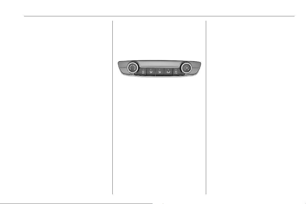
Climate control 151
Climate control
Climate control systems ............. 151
Heating and ventilation system 151
Air conditioning system ........... 152
Electronic climate control
system .................................... 154
Auxiliary heater ........................ 158
Temperature preconditioning ..158
Air vents ..................................... 159
Adjustable air vents ................. 159
Fixed air vents ......................... 160
Maintenance .............................. 160
Air intake ................................. 160
Air conditioning regular
operation ................................ 161
Service .................................... 161
Climate control systems
Heating and ventilation
system
Controls for:
● temperature :
● air distribution w, > and y
● fan speed E
● demisting and defrosting $
● heated rear window and exterior
mirrors f
● heated seats "
Heated rear window 3 24.
Heated exterior mirrors 3 21.
Heated seats 3 30.
Temperature
Adjust the temperature by
turning : to the desired
temperature.
red area : warmer
blue area : colder
Heating will not be fully effective until
the engine has reached normal
operating temperature.
Air distribution
w
: to windscreen and front door
windows
>
: to head area via adjustable air
vents
y
: to foot well and windscreen
All combinations are possible.
Fan speed
Adjust the air flow by turning Z to the
desired speed.
clockwise : increase
anticlockwise : decrease
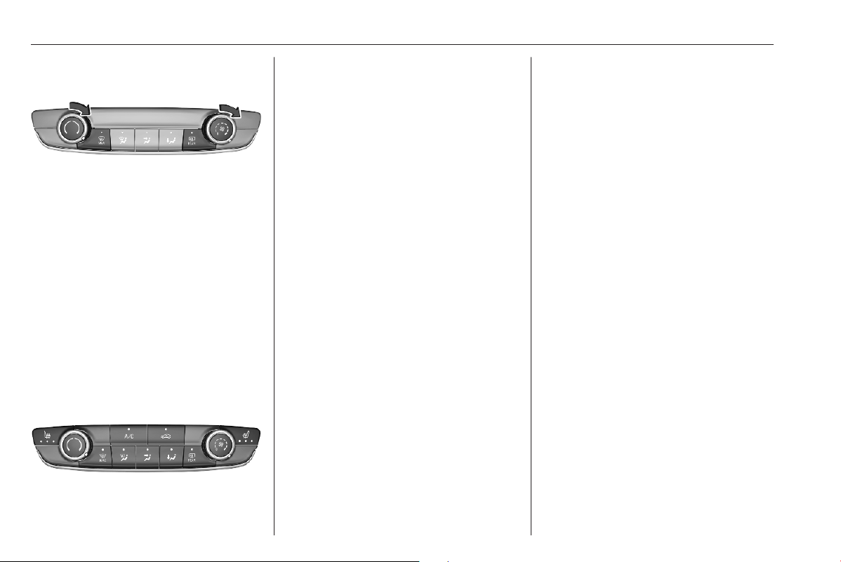
152 Climate control
Demisting and defrosting
● Press $: the air distribution is
directed towards the windscreen.
● Set temperature controller :
to warmest level.
● Set fan speed E to highest level.
● Switch on heated rear window f.
● Open side air vents as required
and direct them towards the door
windows.
Air conditioning system
Controls for:
● temperature :
● air distribution w, x and y
● fan speed E
● demisting and defrosting $
● cooling A/C
● air recirculation n
● heated rear window and exterior
mirrors f
● heated seats "
Heated rear window 3 24.
Heated exterior mirrors 3 21.
Heated seats 3 30.
Some setting changes are indicated
briefly in the Info Display. Activated
functions are indicated by the LED in
the respective button.
Temperature
Adjust the temperature by
turning : to the desired
temperature.
red area : warmer
blue area : colder
Heating will not be fully effective until
the engine has reached normal
operating temperature.
Air distribution
w
: to windscreen and front door
windows
x
: to head area via adjustable air
vents
y
: to foot well and windscreen
All combinations are possible.
Fan speed
Adjust the air flow by turning E to the
desired speed.
clockwise : increase
anticlockwise : decrease
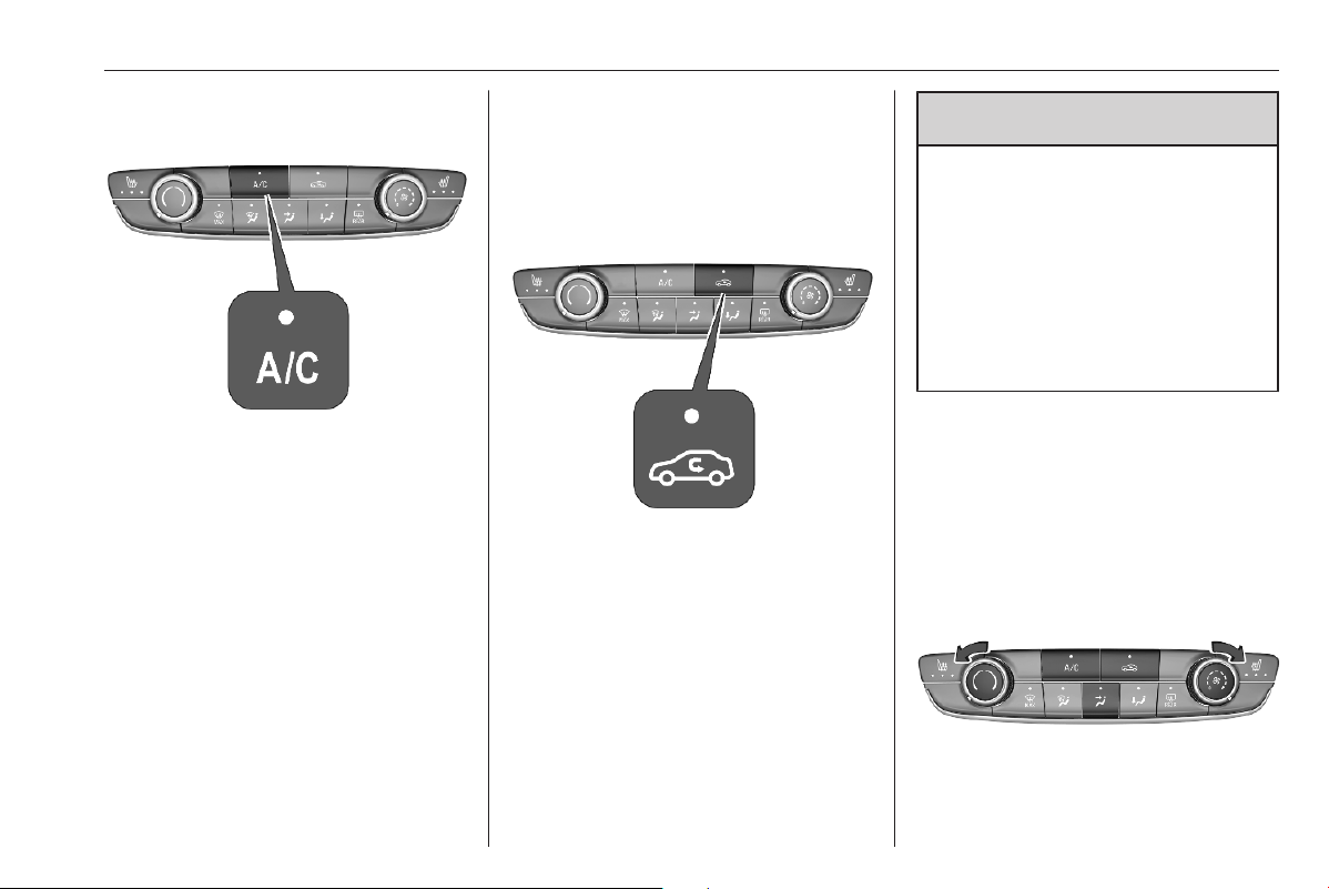
Climate control 153
Cooling A/C
Press A/C to switch on cooling. The
LED in the button illuminates to
indicate activation. Cooling is only
functional when the engine is running
and fan is switched on.
Press A/C again to switch off cooling.
The air conditioning system cools and
dehumidifies (dries) as soon as the
outside temperature is slightly above
the freezing point. Therefore,
condensation may form and drip from
under the vehicle.
If no cooling or drying is required,
switch off the cooling system for fuel
saving reasons.
Activated cooling may inhibit
Autostops.
Stop-start system 3 167.
Air recirculation system
Press n to activate air recirculation
mode. The LED in the button
illuminates to indicate activation.
Press n again to deactivate air
recirculation mode.
9 Warning
The exchange of fresh air is
reduced in air recirculation mode.
In operation without cooling the air
humidity increases, so the
windows may mist up from inside.
The quality of the passenger
compartment air deteriorates,
which may cause the vehicle
occupants to feel drowsy.
In warm and very humid ambient air
conditions, the windscreen may mist
up from outside when cold air is
directed towards it. If windscreen
mists up from outside, activate
windscreen wiper and deactivate w.
Maximum cooling
Briefly open the windows so that hot
air can disperse quickly.
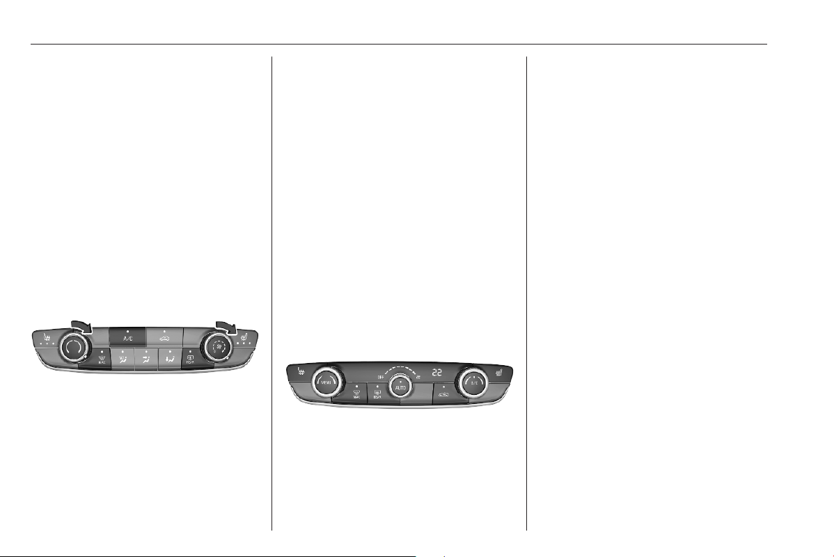
154 Climate control
● Switch on cooling A/C.
● Press n for air recirculation
system on.
● Press x for air distribution.
● Set temperature control : to
coldest level.
● Set fan speed E to highest level.
● Open all vents.
Heated rear window 3 24.
Heated exterior mirrors 3 21.
Demisting and defrosting the
windows
● Press $: the air distribution is
directed towards the windscreen.
● Set temperature controller :
to warmest level.
● Switch on cooling A/C, if
required.
● Switch on heated rear window f.
● Open side air vents as required
and direct them towards the door
windows.
Notice
If à is pressed while the engine is
running, an Autostop will be inhibited
until à is pressed again.
If à is pressed while the engine is in
an Autostop, the engine will restart
automatically.
Stop-start system 3 167.
Electronic climate control
system
Controls for:
● temperature :
● MENU enters the Climate setting
menu in the Info Display
● fan speed E
● automatic mode AUTO
● cooling A/C
● manual air recirculation n
● demisting and defrosting $
● heated rear window and exterior
mirrors f
● heated seats "
Heated rear window 3 24.
Heated exterior mirrors 3 21.
Heated seats 3 30.
In automatic mode, temperature, fan
speed and air distribution are
regulated automatically.
Activated functions are indicated by
the LED in the respective control.
The electronic climate control system
is only fully operational when the
engine is running.
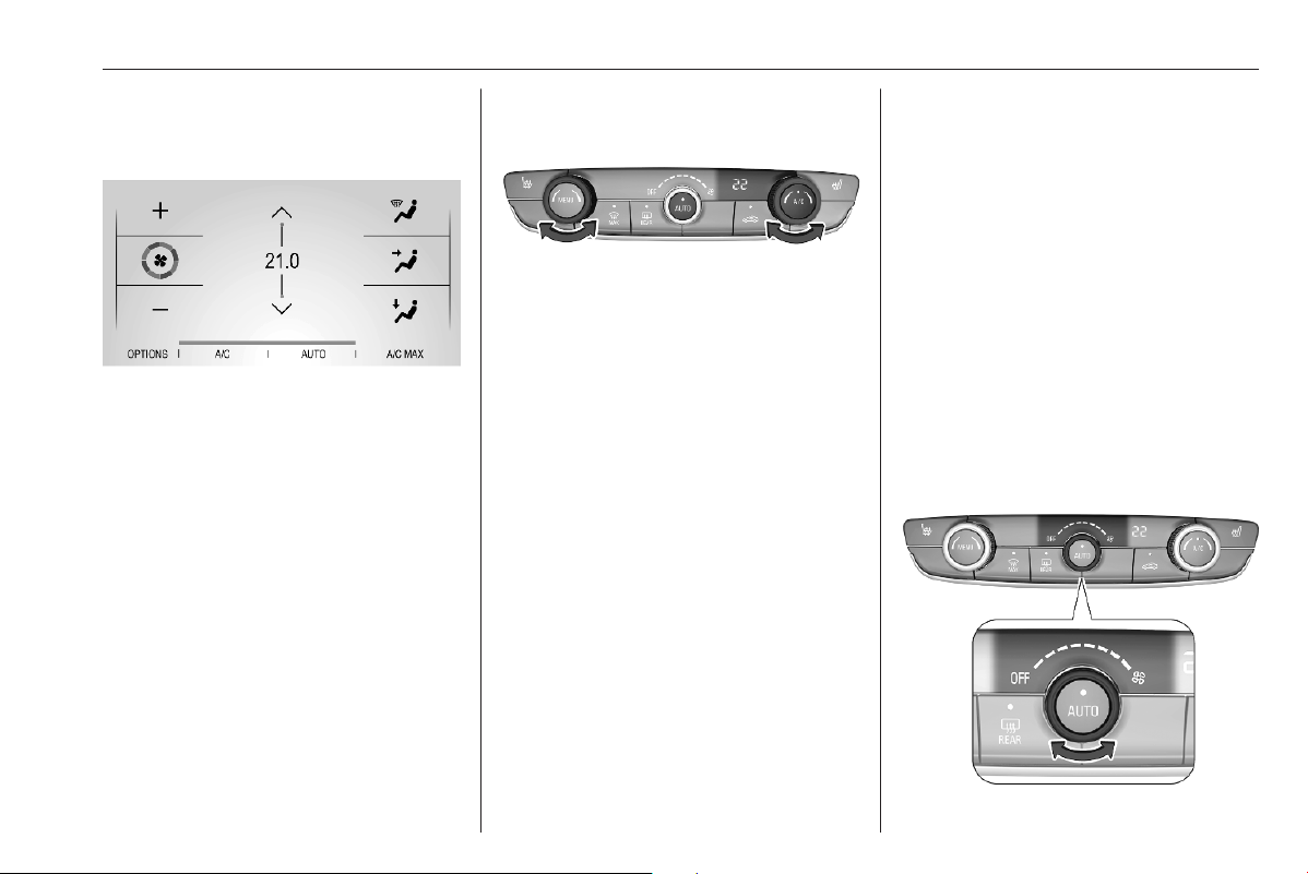
Climate control 155
Climate control settings menu
Press MENU to manually set the
following climate control funtions:
● air distribution w, x and y
● fan speed E
● temperature :
● cooling A/C
● automatic mode AUTO
Climate setting menu can also be
displayed in the Info Display.
Info Display 3 78.
Automatic mode AUTO
Basic setting for maximum comfort:
● Press AUTO, the air distribution
and fan speed are regulated
automatically.
Three different pre-set fan
speeds can be selected by
repeatedly tapping on AUTO
either on the climate control
panel or on the Info Display: soft,
normal or fast. The selected
setting is shown on the Info
Display.
● Open all air vents to allow
optimised air distribution in
automatic mode.
● Air conditioning must be
activated for optimal cooling and
demisting. Press A/C to switch on
air conditioning. The LED in the
button indicates activation.
● Set the preselected temperature
using the left or right rotary knob.
Recommended temperature is
22 °C.
Manual settings
Climate control system settings can
be changed by activating the
following functions:
Fan speed E
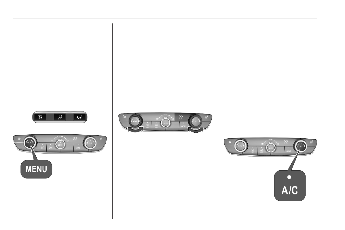
156 Climate control
Adjust the air flow by turning rotary
knob to the desired speed. Fan speed
can also be changed in the climate
settings menu. Press MENU to enter
the menu.
Turn rotary knob anticlockwise as far
as it will go: fan and cooling are
switched off.
To return to automatic mode, press
AUTO.
Air distribution w, x, y
Press MENU to enter the menu.
Touch in the Info Display:
w
: to windscreen and front door
windows
x
: to head area and rear seats via
adjustable air vents
y
: to front and rear foot well and
windscreen
To return to automatic air distribution,
press AUTO.
Temperature preselection :
Set the preselected temperature to
the desired value using the left or the
right rotary knob.
Recommended temperature is 22 °C.
The temperature is indicated in the
display and in the climate settings
menu.
If the minimum temperature Lo is set,
the climate control system runs at
maximum cooling, if cooling A/C is
switched on.
If the maximum temperature Hi is set,
the climate control system runs at
maximum heating.
Notice
If A/C is switched on, reducing the
set cabin temperature can cause the
engine to restart from an Autostop or
inhibit an Autostop.
Stop-start system 3 167.
Air conditioning A/C
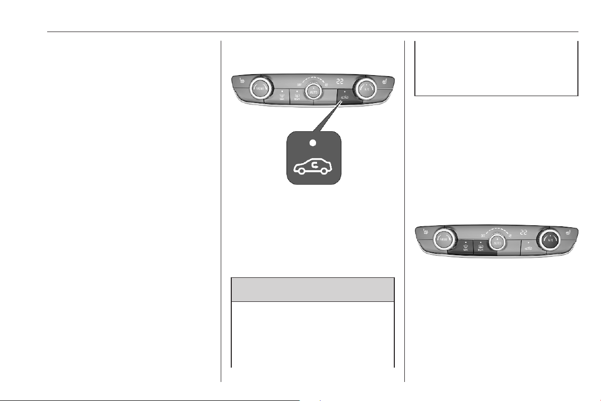
Climate control 157
Press A/C to switch on cooling. The
LED in the button illuminates to
indicate activation. Cooling is only
functional when the engine is running
and climate control fan is switched on.
Press A/C again to switch off cooling.
The air conditioning system cools and
dehumidifies (dries) when outside
temperature is above a specific level.
Therefore, condensation may form
and drip from under the vehicle.
If no cooling or drying is required,
switch off the cooling system for fuel
saving reasons.
Maximum air conditioning AC/MAX
Press MENU to enter the climate
control settings menu.
Touch A/C MAX to activate/
deactivate maximum air conditioning.
The maximum air conditioning
function sets the temperature as low
as possible and adjusts the
distribution to all air vents. In addition,
it sets the air flow to maximum and
activates the air recirculation.
Manual air recirculation
n
Press n to activate the air
recirculation mode. The LED in the
button illuminates to indicate
activation.
Press n again to deactivate
recirculation mode.
9 Warning
The exchange of fresh air is
reduced in air recirculation mode.
In operation without cooling, the
air humidity increases, so the
windows may mist up from inside.
The quality of the passenger
compartment air deteriorates,
which may cause the occupants to
feel drowsy.
In warm and very humid ambient air
conditions, the windscreen may mist
up from outside, when cold air is
directed towards it. If windscreen
mists up from outside, activate
windscreen wiper and deactivate w.
Demisting and defrosting the
windows $
● Press $. The LED in the button
illuminates to indicate activation.
● Temperature and air distribution
are set automatically and the fan
runs at high speed.
● Switch on air conditioning by
pressing A/C, if required.

158 Climate control
● Switch on heated rear window f.
● To return to previous mode,
press $ again. To return to
automatic mode, press AUTO.
Heated rear window 3 24.
Heated exterior mirrors 3 21.
Notice
If à is pressed while the engine is
running, an Autostop will be inhibited
until à is pressed again.
If à is pressed while the engine is in
an Autostop, the engine will restart
automatically.
Stop-start system 3 167.
Deactivation of electronic climate
control system
Cooling, fan and automatic mode can
be switched off by turning one of the
rotary knobs anticlockwise.
Activation by switching on the fan or
pressing AUTO.
Auxiliary heater
Air heater
Quickheat is an electric auxiliary air
heater which automatically warms up
the passenger compartment more
quickly.
Temperature
preconditioning
The temperature preconditioning
allows to heat or to ventilate the
vehicle's interior with ambient air.
The temperature preconditioning can
be programmed via the Info Display
or the MyVauxhall App.
Notice
On vehicles without integrated
navigation system, temperature
preconditioning can only be used via
the MyVauxhall App.
Notice
The temperature preconditioning is
only activated if the ignition is off and
the vehicle is locked.
If the charging level of the high
voltage battery is below 30%, the
temperature preconditioning is not
activated.
When the vehicle is plugged in,
battery charging takes precedence
over pre-conditioning.
Consequently, it can only be
activated if the battery is charged
above a threshold fixed at 80%.
If a recurrent heating / ventilation is
programmed and two heating /
ventilation procedures are carried
out without operating the vehicle, the
programming is deactivated.
Setting timer
Notice
Several timers can be programmed
and saved. It is recommended to
programme temperature
preconditioning with the vehicle
plugged in, in order to optimise the
long-term perfomance of the high
voltage battery.
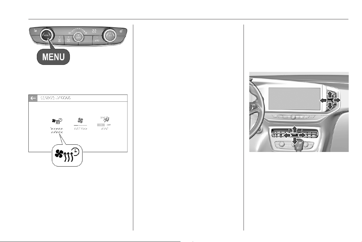
Climate control 159
Press MENU .
Touch OPTIONS.
Select =.
Touch + to define a new timer.
Touch --:--.
Enter time and day.
Press A to confirm the settings.
Press ON to activate the timer.
To delete a timer, press f at the top
of the Info Display and delete the
desired timer.
Confirm the deletion.
The heating / ventilation procedure
starts approx. 45 minutes before the
programmed time, and is maintained
ten minutes after it.
Air vents
Adjustable air vents
Centre air vents in the instrument
panel
Direct the flow of air by tilting and
swivelling the slats.
To close the vent, swivel the slats
inwards.
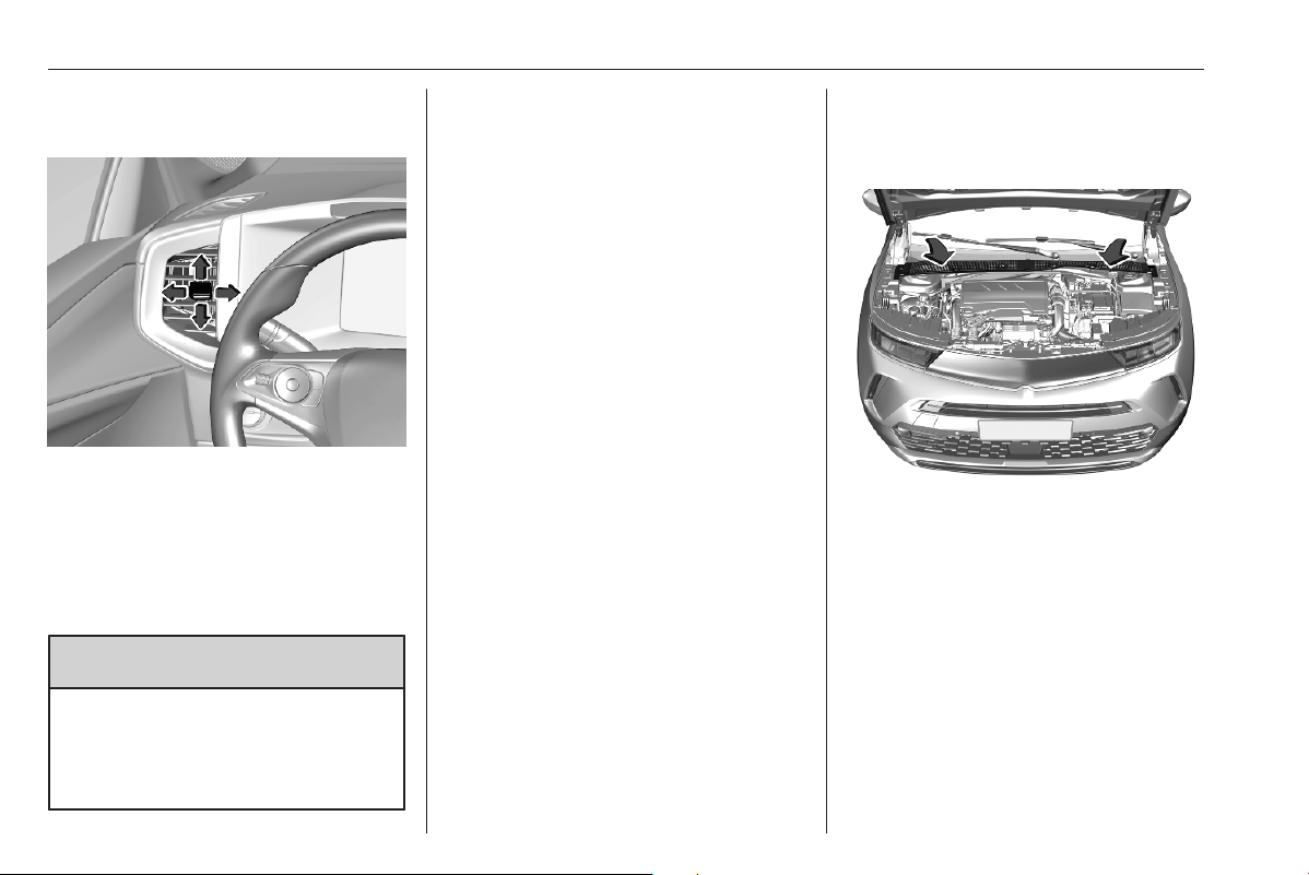
160 Climate control
Outer air vents in the instrument
panel
Direct the flow of air by tilting and
swivelling the slats.
To close the vent, swivel the slats
outwards.
At least two air vents must be open
while cooling is on.
9 Warning
Do not attach any objects to the
slats of the air vents. Risk of
damage and injury in case of an
accident.
Fixed air vents
Additional air vents are located
beneath the windscreen and door
windows and in the foot wells.
Maintenance
Air intake
The air intake in front of the
windscreen in the engine
compartment must be kept clear to
allow air intake. Remove any leaves,
dirt or snow.

Climate control 161
Air conditioning regular
operation
In order to ensure continuously
efficient performance, cooling must
be operated for a few minutes once a
month, irrespective of the weather
and time of year. Operation with
cooling is not possible when the
outside temperature is too low.
Service
For optimal cooling performance, it is
recommended to annually check the
climate control system, starting
three years after initial vehicle
registration, including:
● functionality and pressure test
● heating functionality
● leakage check
● check of drive belts
● cleaning of condenser and
evaporator drainage
● performance check

162 Driving and operating
Driving and
operating
Driving hints ............................... 163
Control of the vehicle ............... 163
Steering ................................... 163
Emergencies ........................... 163
Starting and operating ............... 164
New vehicle running-in ............ 164
Ignition switch positions ........... 164
Power button ........................... 164
Starting the engine .................. 166
Overrun cut-off ........................ 167
Stop-start system .................... 167
Parking .................................... 170
Engine exhaust .......................... 171
Exhaust filter ............................ 171
Catalytic converter ................... 171
AdBlue ..................................... 172
Electric drive unit ....................... 175
Automatic transmission .............. 177
Manual transmission .................. 180
Drive systems ............................ 181
Drive modes ............................ 181
Brakes ........................................ 182
Antilock brake system ............. 182
Parking brake .......................... 183
Brake assist ............................. 185
Hill start assist ......................... 185
Regenerative braking .............. 185
Ride control systems ................. 186
Electronic Stability Control and
Traction Control system ......... 186
Sport mode .............................. 187
Driver assistance systems ......... 187
Cruise control .......................... 188
Speed limiter ........................... 190
Adaptive cruise control ............ 192
Forward collision alert ............. 198
Active emergency braking ....... 200
Automatic post collision
braking .................................... 204
Front pedestrian protection ..... 204
Parking assist .......................... 205
Advanced parking assist ......... 211
Side blind spot alert ................. 216
Rear view camera ................... 217
Traffic sign assistant ................ 220
Lane departure warning .......... 223
Lane keep assist ..................... 224
Advanced lane keep assist ...... 226
Driver alert ............................... 228
Charging .................................... 230
General information ................. 230
Charging types ........................ 231
Charging cable ........................ 232
Programmable charging .......... 237
Charging status ....................... 238
Fuel ............................................ 239
Fuel for petrol engines ............. 239
Fuel for diesel engines ............ 240
Refuelling ................................ 241
Fuel consumption - CO
2
-
Emissions .............................. 242
Trailer hitch ................................ 243
General information ................. 243
Driving characteristics and
towing tips .............................. 243
Trailer towing ........................... 243

Driving and operating 163
Driving hints
Control of the vehicle
Never coast with engine not
running
Many systems will not function in this
situation (e.g. brake servo unit, power
steering). Driving in this manner is a
danger to yourself and others.
All systems function during an
Autostop.
Stop-start system 3 167.
Pedals
To ensure the pedal travel is
uninhibited, there must be no mats in
the area of the pedals.
Use only floor mats, which fit properly
and are fixed by the retainers on the
driver side.
Steering
If power steering assist is lost
because the engine stops or due to a
system malfunction, the vehicle can
be steered but may require increased
effort.
Emergencies
9 Warning
Damage to the high voltage
battery or high voltage system can
create a risk of electric shock,
overheating, or fire.
If the vehicle has been damaged
or affected by a moderate to
severe crash, it must be inspected
as soon as possible by qualified
personnel. Until the technical
inspection has been carried out,
the vehicle must be stored outside
at a minimum distance of
5 metres from any structure or
other flammable objects.
If the vehicle has been damaged
or affected by flood or fire, it must
not be moved at all and has to be
inspected by qualified personnel
as soon as possible.
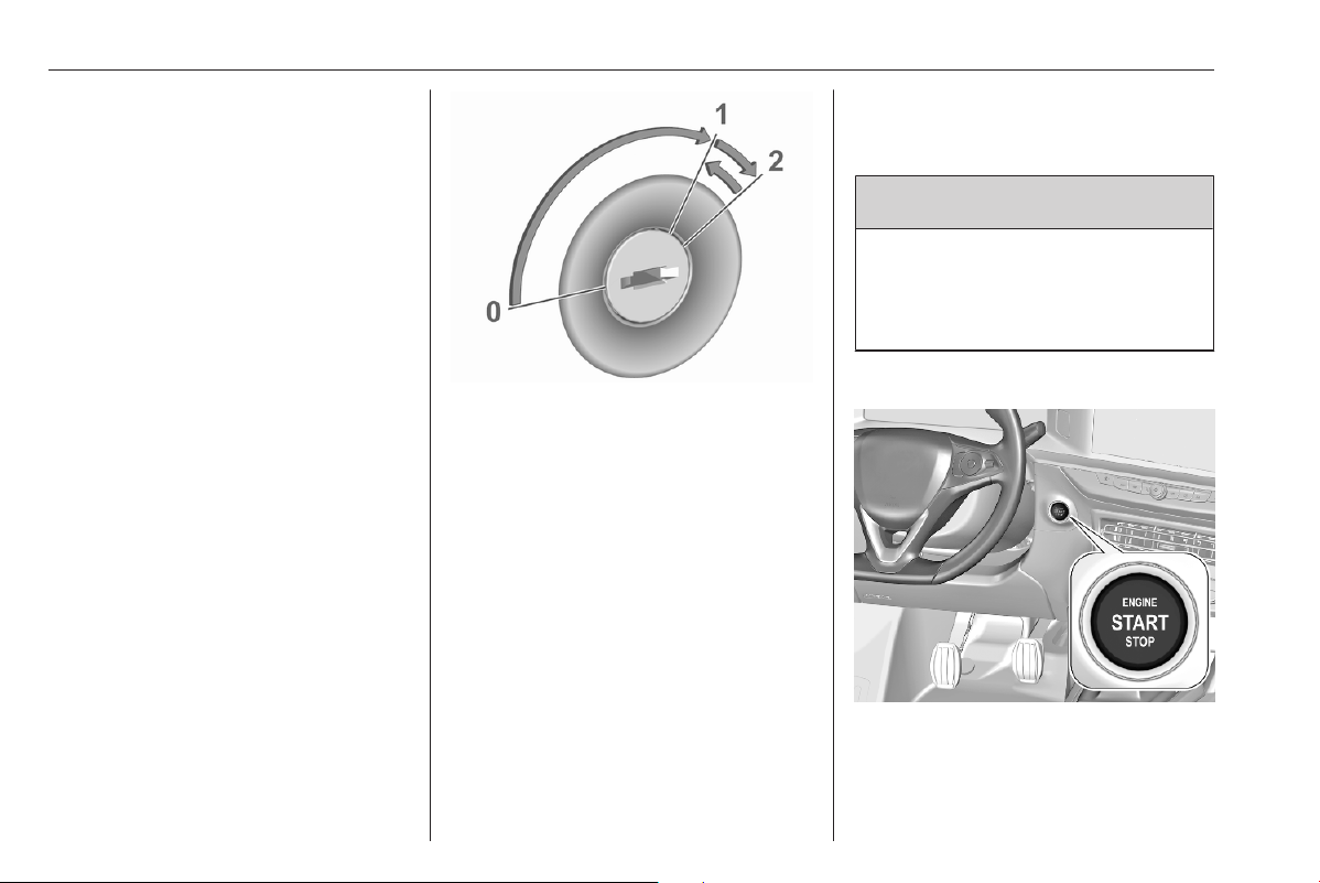
164 Driving and operating
Starting and operating
New vehicle running-in
Do not brake unnecessarily hard for
the first few journeys.
During the first drive, smoke may
occur because of wax and oil
evaporating off the exhaust system.
Park the vehicle in the open for a
while after the first drive and avoid
inhaling the fumes.
During the running-in period, fuel and
engine oil consumption may be
higher.
Additionally, the cleaning process of
the exhaust filter may take place more
often.
Exhaust filter 3 171.
Ignition switch positions
Turn key:
0 : ignition off: some functions
remain active until key is
removed or driver's door is
opened, provided the ignition was
on previously
1 : ignition on power mode: ignition
is on, diesel engine is preheating,
control indicators illuminate and
most electrical functions are
operable
2 : engine start: release key after
engine has been started
Steering wheel lock
Depending on version, the vehicle
may be equipped with a steering
wheel lock.
In this case, remove key from ignition
switch and turn steering wheel until it
engages.
9 Danger
Never remove the key from
ignition switch during driving as
this will cause, depending on
version, steering wheel lock.
Power button
The electronic key must be inside the
vehicle.
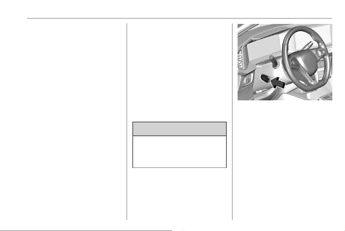
Driving and operating 165
Engine start
Operate the clutch pedal (manual
transmission), the brake pedal and
press Start/Stop.
Ignition on power mode without
starting the engine
Press Start/Stop without operating
clutch or brake pedal. Control
indicators illuminate and most
electrical functions are operable.
Engine and ignition off
Press Start/Stop briefly in each mode
or when engine is running and vehicle
is stationary. Some functions remain
active until driver's door is opened,
provided the ignition was on
previously.
Emergency shut off during driving
Press Start/Stop for 5 seconds
3 166. Depending on version,
steering wheel locks as soon as
vehicle is stationary.
Steering wheel lock
Depending on version, the vehicle
may be equipped with a steering
wheel lock.
In this case, the steering wheel lock
activates automatically when:
● the vehicle is stationary.
● the ignition has been switched
off.
To release steering wheel lock, open
and close driver's door and switch the
ignition on power mode or start the
engine directly.
9 Warning
If the vehicle battery is discharged,
the vehicle must not be towed or
tow-started as the steering wheel
lock cannot be disengaged.
Operation in case of failure
If either the electronic key fails or the
battery of the electronic key is weak,
a message may be displayed in the
Driver Information Centre.
Hold the electronic key at the marking
on the steering column cover as
shown in the illustration.
On vehicles with manual
transmission, select neutral gear,
operate the clutch pedal, the brake
pedal and press Start/Stop.
On vehicles with automatic
transmission, set the selector lever to
position P, operate the brake pedal
and press Start/Stop.
This option is intended for
emergencies only. Replace the
electronic key battery as soon as
possible 3 8.
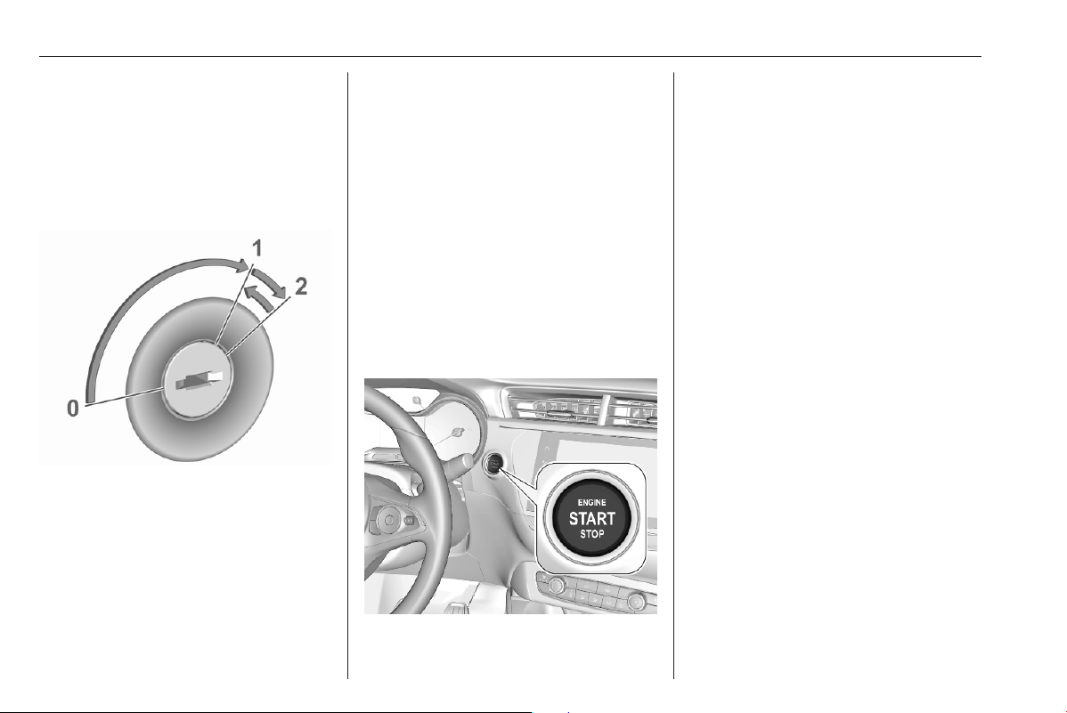
166 Driving and operating
For unlocking or locking the doors,
see fault in radio remote control unit
or electronic key system 3 10.
Starting the engine
Vehicles with ignition switch
Turn key to position 1 to release the
steering wheel lock.
Manual transmission: operate clutch
and brake pedal.
Automatic transmission: operate
brake pedal.
Do not operate accelerator pedal.
Diesel engines: wait until control
indicator z extinguishes.
Turn key briefly to position 2 and
release after engine has been
started.
Manual transmission: during an
Autostop, the engine can be started
by depressing the clutch pedal
3 167.
Automatic transmission: during an
Autostop, the engine can be started
by releasing the brake pedal 3 167.
Vehicles with power button
● Manual transmission: select
neutral gear, operate clutch and
brake pedal.
● Automatic transmission: operate
brake pedal.
● Do not operate accelerator pedal.
● Press Start/Stop button.
● Release button after starting
procedure begins. Diesel engine
starts after control indicator z
for preheating extinguishes.
● Before restarting or to switch off
the engine when vehicle is
stationary, press Start/Stop once
more briefly.
To start the engine during an
Autostop:
● Manual transmission: during an
Autostop, the engine can be
started by depressing the clutch
pedal 3 167.
● Automatic transmission: during
an Autostop, the engine can be
started by releasing the brake
pedal 3 167.

Driving and operating 167
Emergency shut off during driving
If the engine needs to be switched off
during driving in case of emergency,
press Start/Stop for 5 seconds.
9 Danger
Switching off the engine during
driving may cause loss of power
support for brake and steering
systems. Assistance systems and
airbag systems are disabled.
Lighting and brake lights will
extinguish. Therefore power down
the engine and ignition while
driving only when required in case
of emergency.
Starting the vehicle at low
temperatures
Starting the engine without additional
heaters is possible down to -25 °С for
diesel engines and -30 °C for petrol
engines. Required is an engine oil
with the correct viscosity, the correct
fuel, performed services and a
sufficiently charged vehicle battery.
With temperatures below -30 °C the
automatic transmission requires a
warming phase of approx. 5 minutes.
The selector lever must be in position
P.
Turbo engine warm-up
Upon start-up, engine available
torque may be limited for a short time,
especially when the engine
temperature is cold. The limitation is
to allow the lubrication system to fully
protect the engine.
Overrun cut-off
The fuel supply is automatically cut off
during overrun, i.e. when the vehicle
is driven with a gear engaged but
accelerator pedal is released.
Depending on driving conditions, the
overrun cut-off may be deactivated.
Stop-start system
The stop-start system helps to save
fuel and to reduce the exhaust
emissions. When conditions allow, it
switches off the engine as soon as the
vehicle is at a low speed or at a
standstill, e.g. at a traffic light or in a
traffic jam.
Activation
The stop-start system is available as
soon as the engine is started, the
vehicle starts-off and the conditions
as stated below in this section are
fulfilled.
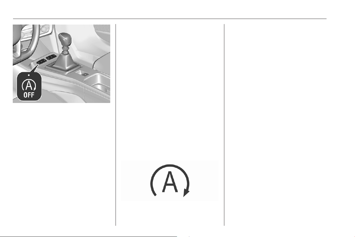
168 Driving and operating
The system is ready to operate when
the LED in the button D is not
illuminated. To activate the system
when the system is deactivated,
press D.
If the stop-start system is temporarily
not available and the button D is
pressed, the LED in the button
flashes.
Deactivation
Deactivate the stop-start system
manually by pressing D. The
deactivation is indicated when the
LED in the button illuminates.
Autostop
Vehicles with manual transmission
Activate an Autostop as follows:
● Set the selector lever to neutral.
● Release the clutch pedal.
The engine will be switched off while
the ignition stays on.
Vehicles with automatic transmission
If the vehicle is at a standstill with
depressed brake pedal, Autostop is
activated automatically.
The engine will be switched off while
the ignition stays on.
The stop-start system will be disabled
on steep inclines.
Indication
An Autostop is indicated by control
indicator n.
During an Autostop, the heating and
brake performance will be
maintained.
Conditions for an Autostop
The stop-start system checks if each
of the following conditions is fulfilled.
● The stop-start system is not
manually deactivated.
● The driver's door is closed or the
driver's seat belt is fastened.
● The vehicle battery is sufficiently
charged and in good condition.
● The engine is warmed up.
● The engine coolant temperature
is not too high.
● The engine exhaust temperature
is not too high, e.g. after driving
with high engine load.
● The ambient temperature is not
too low or too high.
● The climate control system
allows an Autostop.
● The brake vacuum is sufficient.

Driving and operating 169
● The self-cleaning function of the
exhaust filter is not active.
● The vehicle was driven at least at
walking speed since the last
Autostop.
Autostop will be inhibited if these
conditions are not met. In addition,
Autostop may be inhibited
● by certain settings of the climate
control system 3 152
● immediately after higher speed
driving
● in the case of new vehicle
running-in 3 164
● by active demisting
● in the case of steep ascending or
descending slopes
Notice
The Autostop may be inhibited for
several hours after a battery
replacement or reconnection.
Vehicle battery discharge protection
To ensure reliable engine restarts,
several vehicle battery discharge
protection features are implemented
as part of the stop-start system.
Power saving measures
During an Autostop, several electrical
features such as auxiliary electric
heater or rear window heating are
disabled or switched to a power
saving mode. The fan speed of the
climate control system is reduced to
save power.
Restart of the engine by the driver
Vehicles with manual transmission
Depress the clutch pedal without
depressing the brake pedal to restart
the engine.
Vehicles with automatic transmission
The engine is restarted in the
following cases:
● brake pedal released while D or
M is selected
● brake pedal released or N
selected when selector is moved
to select D or M
● selector is moved to select R
Restart of the engine by the stop-
start system
Vehicles with manual transmission:
The selector lever must be in neutral
to enable an automatic restart.
If one of the following conditions
occurs during an Autostop, the
engine will be restarted automatically
by the stop-start system:
● stop-start system manually
deactivated
● driver's seat belt unfastened and
driver's door opened
● engine temperature too low
● charging level of vehicle battery
below a defined level
● brake vacuum not sufficient
● vehicle is driven or rolls at least at
walking speed
● climate control system requests
engine start
● air conditioning manually
switched on
● the bonnet is opened

170 Driving and operating
If an electrical accessory, e.g. a
portable CD player, is connected to
the power outlet, a brief power drop
during the restart might be noticeable.
Parking
9 Warning
● Do not park the vehicle on an
easily ignitable surface. The
high temperature of the
exhaust system could ignite the
surface.
● Apply the parking brake.
● If the vehicle is on a level
surface or uphill slope, engage
first gear or set the selector
lever to position P. On an uphill
slope, turn the front wheels
away from the kerb.
If the vehicle is on a downhill
slope, engage reverse gear or
set the selector lever to position
P. Turn the front wheels
towards the kerb.
● Close the windows.
● Switch off the engine.
● Remove the ignition key from
the ignition switch or switch off
ignition on vehicles with power
button. Depending on version,
turn the steering wheel until the
steering wheel lock is felt to
engage.
● Lock the vehicle.
● Activate the anti-theft alarm
system.
● The engine cooling fans may run
after the engine has been
switched off 3 250.
Caution
After running at high engine
speeds or with high engine loads,
operate the engine briefly at a low
load or run in neutral for
approx. 30 seconds before
switching off, in order to protect
the turbocharger.
Notice
In the event of an accident with
airbag deployment, the engine is
switched off automatically if the
vehicle comes to a standstill within a
certain time.
In countries with extremely low
temperatures it may be necessary to
park the vehicle without applied
parking brake. Make sure to park the
vehicle on a level surface.
Parking brake 3 183.

Driving and operating 171
Engine exhaust
9 Danger
Engine exhaust gases contain
poisonous carbon monoxide,
which is colourless and odourless
and could be fatal if inhaled.
If exhaust gases enter the interior
of the vehicle, open the windows.
Have the cause of the fault
rectified by a workshop.
Avoid driving with an open load
compartment, otherwise exhaust
gases could enter the vehicle.
Exhaust filter
Automatic cleaning process
The exhaust filter system filters soot
particles out of the exhaust gases.
The start of saturation of the exhaust
filter is indicated by the temporary
illumination of t or C,
accompanied by a message in the
Driver Information Centre.
As soon as the traffic conditions
permit, regenerate the filter by driving
at a vehicle speed of at least 40 mph
until the control indicator
extinguishes.
Notice
On a new vehicle, the first exhaust
filter regeneration operations may
be accompanied by a burning smell,
which is normal. Following
prolonged operation of the vehicle at
very low speed or at idle, water
vapour can be emitted at the
exhaust on acceleration. This does
not affect the behaviour of the
vehicle or the environment.
Cleaning process not possible
If t or C stays on, accompanied
by an audible signal and a message,
this indicates that the exhaust filter
additive level is too low.
The reservoir must be topped-up
without delay. Seek the assistance of
a workshop.
Catalytic converter
The catalytic converter reduces the
amount of harmful substances in the
exhaust gases.
Caution
Fuel grades other than those listed
on pages 3 239, 3 288 could
damage the catalytic converter or
electronic components.
Unburnt petrol will overheat and
damage the catalytic converter.
Therefore avoid excessive use of
the starter, running the fuel tank
dry and starting the engine by
pushing or towing.
In the event of misfiring, uneven
engine running, a reduction in engine
performance or other unusual
problems, have the cause of the fault
rectified by a workshop as soon as
possible. In an emergency, driving
can be continued for a short period,
keeping vehicle speed and engine
speed low.

172 Driving and operating
AdBlue
General information
The selective catalytic reduction
(BlueInjection) is a method to
substantially reduce the nitrogen
oxides in the exhaust emission. This
is achieved by injecting a Diesel
Exhaust Fluid (DEF) into the exhaust
system. The ammonia released by
the fluid reacts with nitrous gases
(NO
x
) from the exhaust and turns it
into nitrogen and water.
The designation of this fluid is
AdBlue
®
. It is a non-toxic, non-
flammable, colourless and odourless
fluid which consists of 32% urea and
68% water.
9 Warning
Avoid contact of your eyes or skin
with AdBlue.
In case of eye or skin contact,
rinse off with water.
Caution
Avoid contact of the paintwork with
AdBlue.
In case of contact, rinse off with
water.
AdBlue freezes at a temperature of
approx. -11 °C. As the vehicle is
equipped with an AdBlue pre-heater,
the emissions reduction at low
temperatures is ensured. The AdBlue
pre-heater works automatically.
In some circumstances below the
mentioned temperature, an error
message appears in the Driver
Information Centre. In this event, park
the vehicle in a space with a higher
ambient temperature until AdBlue is
liquefied.
Notice
Frozen and again liquefied AdBlue is
usable without quality loss.
The typical AdBlue consumption is
approx. 2 l per 600 miles, but can also
be higher depending on driving
behaviour (e.g. high load or towing).
Level warnings
Depending on the calculated range of
AdBlue, different messages are
displayed in the Driver Information
Centre. The messages and the
restrictions are a legal requirement.
1. The first warning level is entered
when the estimated AdBlue range
is between 1500 miles and
500 miles.
When switching on the ignition,
this warning will show up once
briefly with the calculated range.
Additionally, control indicator u
will illuminate and a chime will
sound. Driving is possible without
any restrictions.
2. The next warning level is entered
when the estimated AdBlue range
is below 500 miles. The message
with the current range will always
be displayed when ignition is
switched on. Additionally, control
indicator u will flash and a chime
will sound. Refill AdBlue before
entering the next warning level.

Driving and operating 173
3. The next warning level is entered
with a range below 60 miles. The
message with the current range
will always be displayed when
ignition is switched on.
Additionally, control indicator u
will flash and a chime will sound.
Refill AdBlue as soon as possible
before the AdBlue tank is
completely empty. Otherwise, a
restart of the engine will not be
possible.
4. The last warning level is entered
when the AdBlue tank is empty.
Restart of the engine is not
possible.
A message appears in the Driver
Information Centre. Additionally,
control indicator u will flash and
a chime will sound.
Refill the tank to a level of at least
5 l of AdBlue, otherwise restarting
of the engine is not possible.
High emission warnings
In the event of a fault with the
emissions control system, different
messages are displayed in the Driver
Information Centre.
The messages and the restrictions
are a legal requirement. The warning
messages are accompanied by the
control indicators u, C and W.
Additionally, a chime will sound.
Follow the instructions of the warning
messages. If starting is prevented,
seek the assistance of a workshop.
Refilling AdBlue
Caution
Only use AdBlue that complies
with European standards
DIN 70 070 and ISO 22241-1.
Do not use additives.
Do not dilute AdBlue.
Otherwise the selective catalytic
reduction system could be
damaged.
Notice
Whenever a filling pump with a
nozzle for passenger cars is not
available at a filling station, use only
AdBlue bottles or canisters with a
sealed refill adapter for refilling, to
prevent splashback and overspill,
and in order to ensure that the fumes
from the tank are captured and do
not emerge. AdBlue in bottles or
canisters is available in many filling
stations and can be purchased e.g.
at Vauxhall dealers and other retail
outlets.
Since AdBlue has a limited
durability, check the date of expiry
before refilling.
Notice
Refill the AdBlue tank to a level of at
least 10 l, to ensure that the new
AdBlue level is being detected.
In case AdBlue refill is not
successfully detected:
1. Continuously drive the vehicle
for ten minutes making sure that
vehicle speed is always higher
than 12 mph.
2. If AdBlue refill is detected
successfully, AdBlue supply-
driven warnings or limitations will
disappear.
If AdBlue refill is still not detected,
seek the assistance of a workshop.
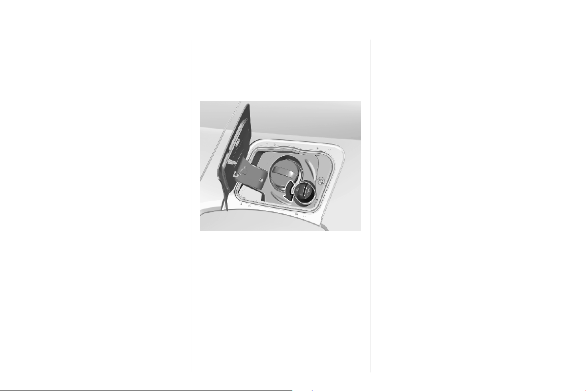
174 Driving and operating
If AdBlue must be refilled at
temperatures below -11 °C, the
refilling of AdBlue may not be
detected by the system. In this
event, park the vehicle in a space
with a higher ambient temperature
until AdBlue is liquified.
Notice
When unscrewing the protective cap
from the filler neck, ammonia fumes
may emerge. Do not inhale as the
fumes have a pungent smell. The
fumes are not harmful by inhalation.
The AdBlue tank should be filled
completely. This must be done if the
warning message regarding
prevention of an engine restart is
already displayed.
AdBlue refilling quantity 3 290.
The vehicle must be parked on a level
surface.
The filler neck for AdBlue is located
behind the fuel filler flap.
The fuel filler flap can only be opened
if the vehicle is unlocked.
1. Switch off the ignition.
2. Close all doors to avoid ammonia
fumes entering the interior of the
vehicle.
3. Release the fuel filler flap by
pushing the flap 3 241.
4. Unscrew protective cap from the
filler neck.
5. Open AdBlue canister.
6. Mount one end of the hose on the
canister and screw the other end
on the filler neck.
7. Lift the canister until it is empty, or
until the flow from the canister has
stopped.
8. Place the canister on the ground
to empty the hose, wait
15 seconds.
9. Unscrew the hose from the filler
neck.
10. Mount the protective cap and turn
clockwise until it engages.
Notice
Dispose of AdBlue canister
according to environmental
requirements. Hose can be reused
after flushing with clear water before
AdBlue dries out.
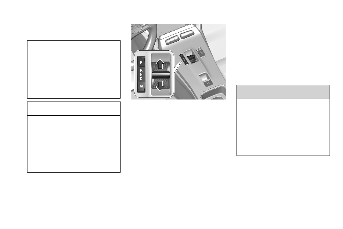
Driving and operating 175
Electric drive unit
Caution
If the vehicle seems to accelerate
slowly or not respond when you try
to go faster, do not continue your
journey. The electric drive unit
could be damaged. Consult a
workshop as soon as possible.
Caution
Spinning the tyres or holding the
vehicle in one place on a hill using
only the accelerator pedal may
damage the electric drive unit. If
you are stuck, do not spin the
tyres. When stopping on a hill, use
the brakes to hold the vehicle in
place.
The vehicle uses an electric drive unit
with a 1-gear transmission. The
selector is located on the centre
console between the seats.
P : park position
R : reverse gear
N : neutral
D : automatic mode
B : automatic mode with one-pedal
driving
After selecting a mode, the selector
will return to the centre position. The
selected mode is indicated in the
Driver Information Centre.
Do not accelerate while engaging a
mode. Never depress the accelerator
pedal and brake pedal at the same
time.
When D or R is selected, the vehicle
slowly begins to creep when the
brake is released.
Park position P
9 Warning
Do not leave the vehicle when the
propulsion system is running, the
vehicle may move suddenly. You
or others can be injured. To be
sure the vehicle will not move,
even if you are on even ground,
make sure the parking brake is
applied and P is selected.
To shift into P, press button P when
vehicle is stationary. In P, the front
wheels of the vehicle are blocked.
To shift out of P, depress the brake
pedal and select the desired mode.
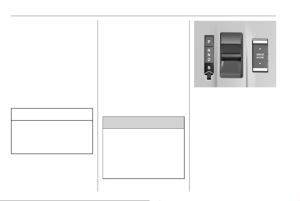
176 Driving and operating
The vehicle shifts automatically into
P when
● the ignition is switched off
● the driver's door is opened while
the vehicle's speed is below
1 mph
The vehicle will not shift into P if it is
moving too fast. Stop the vehicle and
shift into P.
Reverse gear R
To shift into and out of R, the vehicle
must be at standstill and the brake
pedal has to be depressed.
Caution
Shifting into R while the vehicle is
moving forwards could damage
the electric drive unit. Only shift
into R after the vehicle has been
stopped.
Neutral N
In this position, the propulsion system
does not transfer torque to the
wheels.
Automatic mode D
This mode is for normal driving.
To shift into and out of D, the vehicle
must be at standstill and the brake
pedal has to be depressed.
Automatic mode B with one-pedal
driving
In this mode, vehicle speed is
significantly reduced by releasing the
accelerator pedal, without operating
the brake pedal.
Use B when driving down steep hills,
in deep snow, in mud or in stop-and-
go traffic.
9 Warning
In the case of extreme
temperatures or if the high voltage
battery is almost fully charged, the
brake force of the engine braking
may be temporarily reduced. If the
braking force is not sufficient, the
driver has to be prepared to use
the brake pedal.
Press button B.
To deactivate B, press button B.
Regenerative braking 3 185.
Free wheeling / car wash mode
In certain situations, e.g., in an
automatic car wash etc., it is
necessary that the wheels can move
freely when the engine is switched off.
To avoid that the vehicle shifts
automatically from N into P, enable
free wheeling:
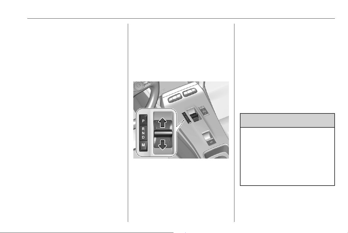
Driving and operating 177
With the vehicle stationary and the
engine running, proceed as follows:
1. Depress the brake pedal and
select N.
2. Within 5 seconds, depress and
hold the brake pedal, switch off
ignition and move the selector
forwards or backwards.
3. Release the brake pedal and
switch on ignition.
4. Depress and hold the brake pedal
and push the switch j.
5. Release the brake pedal and
switch off ignition.
A message is displayed in the Driver
Information Centre indicating that the
wheels are unblocked for the next 15
minutes.
To revert to normal operation,
depress the brake pedal, switch on
the engine and select P.
Parking brake 3 183.
Automatic transmission
The automatic transmission permits
automatic gearshifting (automatic
mode) or manual gearshifting
(manual mode).
Selector operation
P : park position
R : reverse gear
N : neutral
D : automatic mode
M : manual mode
After selecting a mode, the selector
will return to the centre position. The
selected mode is indicated in the
Driver Information Centre.
Do not accelerate while engaging a
mode. Never depress the accelerator
pedal and brake pedal at the same
time.
When D or R is selected, the vehicle
slowly begins to creep when the
brake is released.
Park position P
9 Warning
Do not leave the vehicle when the
propulsion system is running, the
vehicle may move suddenly. You
or others can be injured. To be
sure the vehicle will not move,
even if you are on even ground,
make sure the parking brake is
applied and P is selected.
To shift into P, press button P when
vehicle is stationary. In P, the front
wheels of the vehicle are blocked.

178 Driving and operating
To shift out of P, depress the brake
pedal and select the desired mode.
The vehicle shifts automatically into
P when
● the ignition is switched off
● the driver's door is opened while
the vehicle's speed is below
1 mph
The vehicle will not shift into P if it is
moving too fast. Stop the vehicle and
shift into P.
Reverse gear R
To shift into and out of R, the vehicle
must be at standstill and the brake
pedal has to be depressed.
Caution
Shifting into R while the vehicle is
moving forward could damage the
automatic transmission. Only shift
into R after the vehicle has been
stopped.
Neutral N
In this position, the propulsion system
does not transfer torque to the
wheels.
When N is selected and ignition is
switched off, P is engaged after a
short time.
Automatic mode D
This mode is for normal driving.
To shift into and out of D, the vehicle
must be at standstill and the brake
pedal has to be depressed.
Engine braking
To utilise the engine braking effect,
select a lower gear in good time when
driving downhill.
Free wheeling / car wash mode
In certain situations, e.g., in an
automatic car wash etc., it is
necessary that the wheels can move
freely when the engine is switched off.
To avoid that the vehicle shifts
automatically from N into P, enable
free wheeling:
With the vehicle stationary and the
engine running, proceed as follows:
1. Depress the brake pedal and
select N.
2. Within 5 seconds, depress and
hold the brake pedal, switch off
ignition and move the selector
forwards or backwards.
3. Release the brake pedal and
switch on ignition.
4. Depress and hold the brake pedal
and push the switch j.
5. Release the brake pedal and
switch off ignition.
A message is displayed in the Driver
Information Centre indicating that the
wheels are unblocked for the next 15
minutes.
To revert to normal operation,
depress the brake pedal, switch on
the engine and select P.
Parking brake 3 183.
Deactivation of the automatic
operation of the electric parking brake
For this procedure, refer to the
description of the automatic parking
brake.
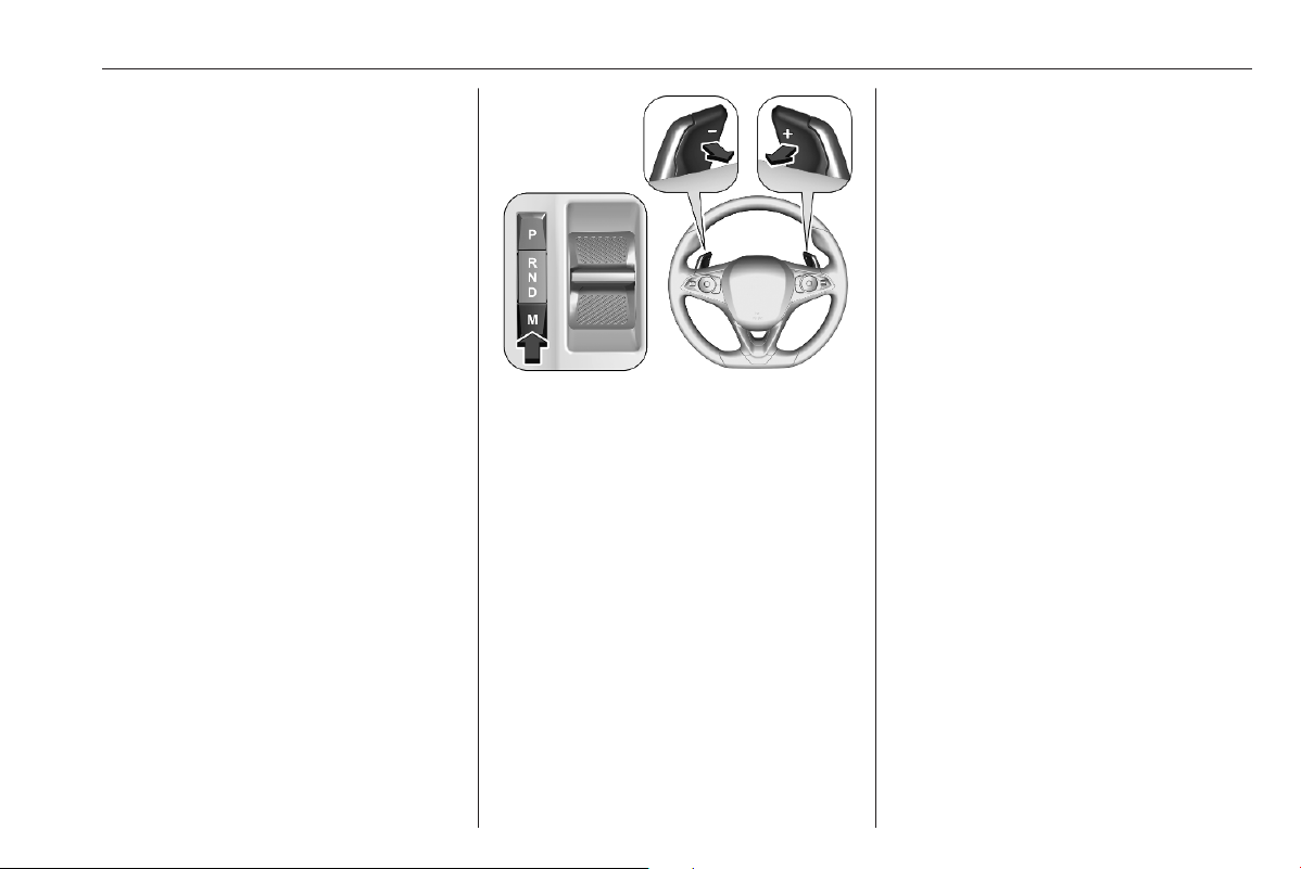
Driving and operating 179
Parking brake 3 183
Manual mode
Manual mode M can be activated
from position D in each driving
situation and speed.
The selected gear is indicated in the
Driver Information Centre.
If a higher gear is selected when
vehicle speed is too low, or a lower
gear when vehicle speed is too high,
the shift is not executed. This can
cause a message in the Driver
Information Centre.
In manual mode, no automatic
shifting to a higher gear takes place
at high engine revolutions.
Press button M.
Pull steering wheel paddles to select
gears manually.
Pull right paddle + to shift to a higher
gear.
Pull left paddle - to shift to a lower
gear.
Multiple pulls allow gears to be
skipped.
Gear shift indication
The symbol Y or Z with a number
beside it is indicated when
gearshifting is recommended for fuel
saving reasons.
Shift indication appears only in
manual mode.
Engine braking
To utilise the engine braking effect,
select a lower gear in good time when
driving downhill.
Electronic driving programmes
Following a cold start, the operating
temperature programme increases
engine speed to quickly bring the
catalytic converter to the required
temperature.
Special programmes automatically
adapt the shifting points when driving
up inclines or down hills.
In snowy or icy conditions or on other
slippery surfaces, the electronic
transmission control enables the
driver to select manually first, second
or third gear for starting off.
Kickdown
Pressing down the accelerator pedal
beyond the kickdown detent will lead
to maximum acceleration
independent of selected driving
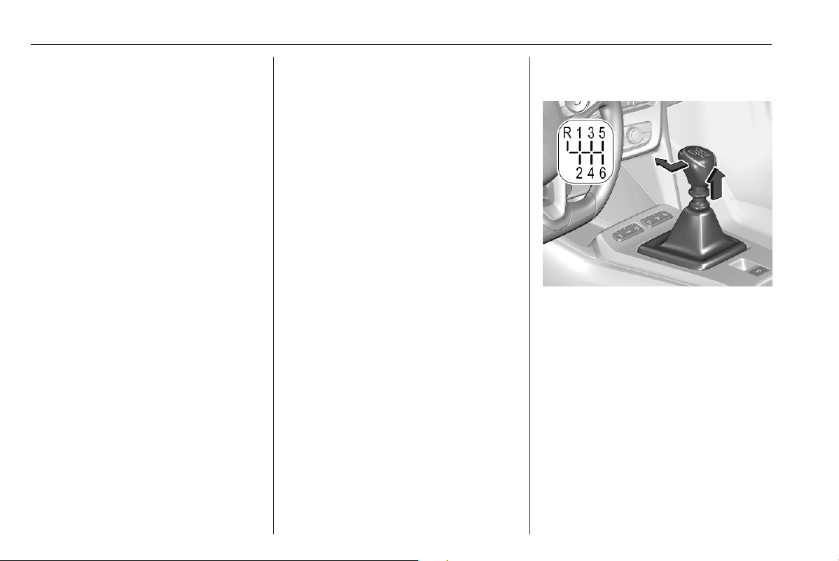
180 Driving and operating
mode. The transmission shifts to a
lower gear depending on engine
speed.
Fault
In the event of a fault, C illuminates
a message is displayed in the Driver
Information Centre.
Vehicle messages 3 80.
Electronic transmission control
enables only third gear. The
transmission no longer shifts
automatically.
Do not drive faster than 62 mph.
Have the cause of the fault remedied
by a workshop.
Interruption of power supply
In the event of an interruption of
power supply, it is not possible to
select another mode when P is
selected.
Towing the vehicle 3 274.
If the vehicle battery is discharged,
start the vehicle using jump leads
3 273.
If the vehicle battery is not the cause
of the fault, seek the assistance of a
workshop.
Manual transmission
To engage reverse, depress the
clutch pedal, pull the ring under the
selector lever and move the selector
lever quite to the left and front.
If the gear does not engage, set the
selector lever to neutral, release the
clutch pedal and depress again. Then
repeat gear selection.
Do not slip the clutch unnecessarily.
When operating, depress the clutch
pedal completely. Do not use the
pedal as a foot rest.
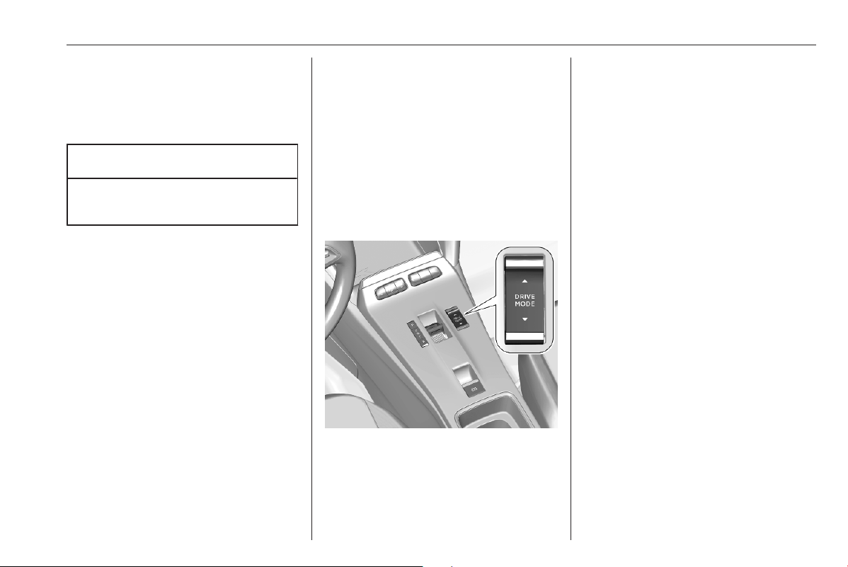
Driving and operating 181
When clutch slip is detected for a
specific time, the engine power will be
reduced. A warning is displayed in the
Driver Information Centre. Release
the clutch.
Caution
It is not advisable to drive with the
hand resting on the selector lever.
Gear shift indication 3 72.
Stop-start system 3 167.
Drive systems
Drive modes
Following drive modes are selectable:
● Normal mode
● Sport mode
● Eco mode
Each drive mode corresponds to a
different vehicle setting.
To select the respective drive mode,
use the shown toggle switch.
Normal mode
The settings in this mode are set by
default. Everytime the ignition is
switched on, this mode is selected.
BEV: To optimise range, electric
engine power output is reduced.
Sport mode
The settings in this mode allow more
dynamic driving. The vehicle's
dynamic parameters can be
displayed in the Driver Information
Centre.
BEV: This mode allows maximum
electric engine power output.
Eco mode
Reduces fuel consumption by
optimising the operation of the
heating and air conditioning and,
depending on version, the accelerator
pedal, the automatic transmission
and the gear shifting indicator.
While coasting the vehicle, the engine
is idling with reduced engine brake.
BEV: To optimise range, electric
engine power output is reduced and
heating is switched off.
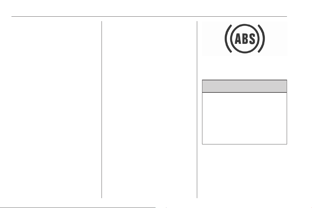
182 Driving and operating
Propulsion types 3 4.
Brakes
Antilock brake system
Antilock brake system (ABS)
prevents the wheels from locking.
ABS starts to regulate brake pressure
as soon as a wheel shows a tendency
to lock. The vehicle remains
steerable, even during hard braking.
ABS control is made apparent
through a pulse in the brake pedal
and the noise of the regulation
process.
For optimum braking, keep the brake
pedal fully depressed throughout the
braking process, despite the fact that
the pedal is pulsating. Do not reduce
the pressure on the pedal.
When braking in an emergency, the
hazard warning flashers are switched
on automatically depending on the
force of deceleration. They are
switched off automatically the first
time you accelerate.
After starting off, the system performs
a self-test which may be audible.
Control indicator i 3 72.
Fault
9 Warning
If there is a fault in the ABS, the
wheels may be liable to lock due
to braking that is heavier than
normal. The advantages of ABS
are no longer available. During
hard braking, the vehicle can no
longer be steered and may
swerve.
Have the cause of the fault remedied
by a workshop.
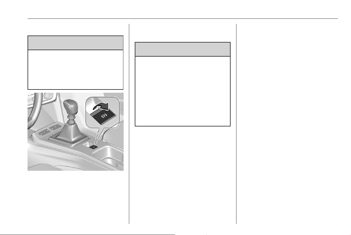
Driving and operating 183
Parking brake
9 Warning
Before leaving the vehicle, check
parking brake status. Control
indicator j illuminate constantly
when electric parking brake is
applied.
Applying when vehicle is
stationary
9 Warning
Pull switch m for a minimum of
1 second until control indicator m
illuminates constantly and electric
parking brake is applied. The
electric parking brake operates
automatically with adequate force.
Before leaving the vehicle, check
the electric parking brake status.
Control indicator m 3 71.
The electric parking brake can always
be activated, even if the ignition is off.
Do not operate electric parking brake
system too often without engine
running as this will discharge the
vehicle battery.
Releasing
Switch on ignition. Keep foot brake
pedal depressed and then push
switch j.
Drive away function
Vehicles with manual transmission:
Depressing the clutch pedal and then
slightly releasing the clutch pedal and
slightly depressing the accelerator
pedal releases the electric parking
brake automatically. This is only
possible if the automatic operation of
the electric parking brake is activated.
It is not possible when switch j is
pulled at the same time.
Vehicles with automatic transmission:
Engaging R, D or M and then
depressing the accelerator pedal
releases the electric parking brake
automatically. This is only possible if
the automatic operation of the electric
parking brake is activated. It is not
possible when switch j is pulled at
the same time.
Braking when vehicle is moving
When the vehicle is moving and the
switch j is kept pulled, the electric
parking brake system will decelerate
the vehicle. As soon as the switch
j is released, braking will be
stopped.

184 Driving and operating
The antilock brake system and the
Electronic Stability Control stabilise
the vehicle while the switch j is kept
pulled. If an error of the electric
parking brake occurs, a warning
message is displayed in the driver
information centre. If the antilock
brake system and the Electronic
Stability Control fail, one or both
indicators i and J illuminate in the
Driver Information Centre. In this
case, stability during deceleration of
the vehicle can only be maintained
with repeated short pulls of the switch
until the vehicle is immobilised.
Automatic operation
Automatic operation includes
automatic application and automatic
release of the electric parking brake.
The electric parking brake can also be
applied or released manually by using
the switch j.
Automatic application:
● The electric parking brake is
automatically applied when the
vehicle is stationary and the
ignition is switched off.
● j illuminates in the Driver
Information Centre and a display
message pops up to confirm the
application.
Automatic release:
Notice
The automatic release of the electric
parking brake is inhibited as long as
the driver's door is open.
● Parking brake releases
automatically on driving off.
● j extinguishes in the Driver
Information Centre and a display
message pops up to confirm the
release.
Deactivation of automatic
operation
In certain situations, e.g. in extreme
cold weather conditions or when
towing, it may be necessary to
deactivate the automatic operation of
the electric parking brake.
1. Start the engine.
2. If the parking brake is released,
pull the switch j to apply the
parking brake.
3. Take your foot off the brake pedal.
4. Press the switch j for at least
10 seconds and maximum
15 seconds.
5. Release the switch j.
6. Depress and hold the brake
pedal.
7. Pull the switch j for 2 seconds.
The deactivation of the automatic
operation of the electric parking brake
is confirmed by o illuminating in the
Driver Information Centre. The
electric parking brake can only be
applied and released manually.

Driving and operating 185
The deactivation of the automatic
operation of the electric parking brake
is confirmed by o illuminating in the
Driver Information Centre 3 72. The
electric parking brake can only be
applied and released manually.
To reactivate the automatic
operation, repeat the steps described
above.
Fault
Failure mode of electric parking brake
is indicated by a control indicator
k and by a message displayed in
the Driver Information Centre.
Vehicle messages 3 80.
Control indicator j flashes: electric
parking brake is not fully applied or
released. When continuously
flashing, release electric parking
brake and retry applying.
Brake assist
If brake pedal is depressed quickly
and forcefully, maximum brake force
is automatically applied.
Operation of brake assist might
become apparent by a pulse in the
brake pedal and a greater resistance
when depressing the brake pedal.
Maintain steady pressure on the
brake pedal as long as full braking is
required. Maximum brake force is
automatically reduced when brake
pedal is released.
Hill start assist
The system helps prevent unintended
movement when driving away on
inclines.
When releasing the brake pedal after
stopping on an incline and certain
slope conditions are met, brakes
remain on for further 2 seconds. The
brakes release automatically as soon
as the vehicle begins to accelerate.
Regenerative braking
9 Warning
In the case of extreme
temperatures or if the high voltage
battery is almost fully charged, the
brake force of the engine braking
may be temporarily reduced. If the
braking force is not sufficient, the
driver has to be prepared to use
the brake pedal.
9 Warning
Depending on the engine braking
force the brake lights are
illuminated.
Regenerative braking generates
electrical energy resulting from
engine braking to charge the high
voltage battery.
Electric drive unit 3 175.
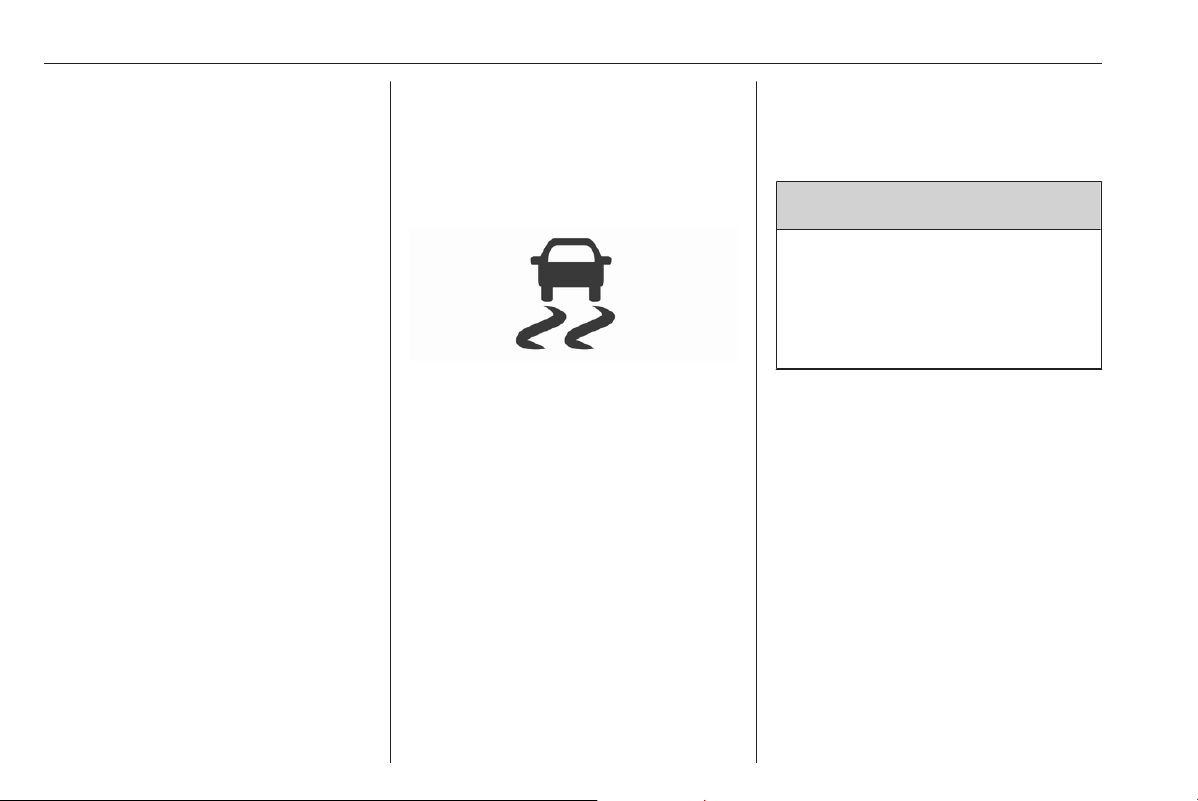
186 Driving and operating
Ride control systems
Electronic Stability Control
and Traction Control system
Electronic Stability Control improves
driving stability when necessary,
regardless of the type of road surface
or tyre grip.
As soon as the vehicle starts to
swerve (understeer / oversteer),
engine output is reduced and the
wheels are braked individually.
Electronic Stability Control operates
in combination with the Traction
Control system. It prevents the driven
wheels from spinning.
The Traction Control system is a
component of the Electronic Stability
Control.
The Traction Control system
improves driving stability when
necessary, regardless of the type of
road surface or tyre grip, by
preventing the driven wheels from
spinning.
As soon as the driven wheels starts to
spin, engine output is reduced and
the wheel spinning the most is braked
individually. This considerably
improves the driving stability of the
vehicle on slippery road surfaces.
Electronic Stability Control and the
Traction Control system are
operational after each engine start as
soon as the control indicator J
extinguishes.
When Electronic Stability Control or
the Traction Control system operates,
J flashes.
When Electronic Stability Control or
the Traction Control system is not
operational, J illuminates
accompanied by a message in the
Driver Information Centre.
After reconnecting the vehicle
battery, the system needs a
recalibration by driving a short
distance.
9 Warning
Do not let this special safety
feature tempt you into taking risks
when driving.
Adapt speed to the road
conditions.
Control indicator J 3 73.
Deactivation
The Traction Control system can be
deactivated in the Info Display.
Info Display 3 78.
Deactivation is confirmed by a
message in the Driver Information
Centre.
Fault
If there is a fault in the system, the
control indicator J illuminates
continuously, a message appears in
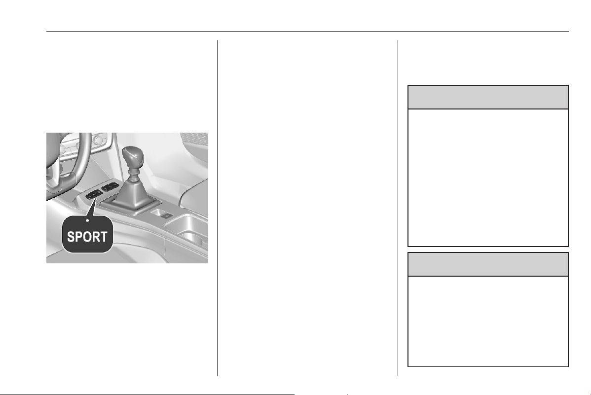
Driving and operating 187
the Driver Information Centre and a
warning chime sounds. The system is
not operational.
Have the cause of the fault remedied
by a workshop.
Sport mode
Sport mode adapts the settings of
some vehicle systems to a sportier
driving style:
● The engine reacts more quickly
to accelerator pedal changes.
● Steering support is sportier.
Activation
Press SPORT when engine is
running.
The LED in the button illuminates
when sport mode is active.
Deactivation
Press SPORT. The LED in the button
extinguishes when sport mode is
deactivated.
Driver assistance
systems
9 Warning
Driver assistance systems are
developed to support the driver
and not to replace the driver's
attention.
The driver accepts full
responsibility when driving the
vehicle.
When using driver assistance
systems, always take care
regarding the current traffic
situation.
9 Warning
The usage of a license plate
support on the front bumper may
affect the proper radar unit
functionality.
When using a license plate
support, follow the markings and
indications on the front bumper.
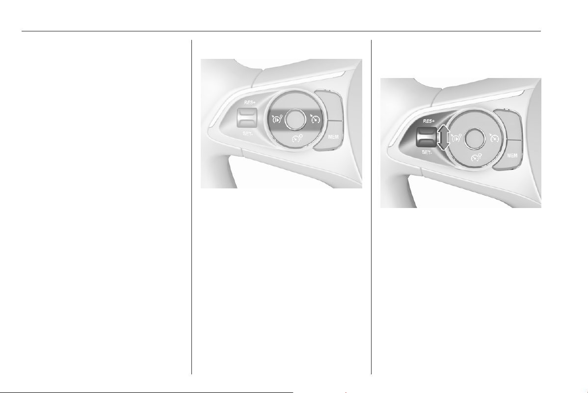
188 Driving and operating
Cruise control
The cruise control can store and
maintain speeds above 25 mph.
Additionally, at least the third gear
must be engaged on some manual
transmissions. On automatic
transmission, position D or the
second or a higher gear in position
M must be selected.
Deviations from the stored speeds
may occur when driving uphill or
downhill.
The system maintains the vehicle
speed at the preset speed by the
driver, without any action on the
accelerator pedal.
The preset speed can be exceeded
temporarily by pressing the
accelerator pedal firmly.
The status and preset speed is
displayed in the Driver Information
Centre.
Do not use the cruise control if it is not
advisable to maintain a constant
speed.
Switching on the system
Press v.
Symbol v and a message are
displayed in the Driver Information
Centre. The system is still not active.
Activation of the functionality
Setting speed by the driver
Accelerate to the desired speed and
move thumb wheel once briefly to
SET/-. The current speed is stored
and maintained. Accelerator pedal
can be released.
The preset speed can then be
changed by moving thumb wheel to
RES/+ to increase or SET/- to
decrease the speed. Move thumb
wheel repeatedly to change speed in
small steps, move and hold to change
speed in large steps.

Driving and operating 189
Speed value is indicated in the Driver
Information Centre.
Adopting speed by the speed limit
recognition
A detected speed limit can be used as
new value for the cruise control.
If the cruise control is active, MEM
illuminates if the difference between
set speed and speed limit is more
than 6 mph.
Press MEM on the steering wheel to
request saving of the suggested
speed.
Press MEM on the steering wheel
once more to confirm and save the
new speed setting.
The function can be activated or
deactivated in the vehicle
personalisation 3 81.
Traffic sign assistant 3 220.
Exceeding the set speed
Vehicle speed can be increased by
depressing the accelerator pedal.
When the accelerator pedal is
released, the previously stored speed
is resumed.
Deactivation of the functionality
Press i, cruise control is in pause
mode and a message is displayed.
The vehicle is driven without cruise
control.
Cruise control is deactivated, but not
switched off. Last stored speed
remains in memory for later speed
resume.
Cruise control is deactivated
automatically in the following cases:
● The brake pedal is depressed.
● Vehicle speed is below 25 mph.
● The traction control system or
electronic stability control is
operating.
● The selector lever is in N
(automatic transmission) or the
first or second gear (on some
manual transmissions) is
engaged.
● The clutch pedal has been
depressed for a few seconds
(depending on the manual
transmission).
Resume stored speed
Move thumb wheel to RES/+ at a
speed above 25 mph. The stored
speed will be obtained.
Switching off the system
Press v, the cruise control mode is
deselected and the cruise control
indication extinguishes in the Driver
Information Centre.
Pressing 5 to activate the speed
limiter deactivates cruise control.
Switching off the ignition cancels any
programmed speed value.
Fault
In the event of a cruise control fault,
the speed is cleared resulting in
flashing of the dashes.
The speed limit recognition may not
operate correctly if traffic signs do not
comply with the Vienna Convention
on Road Signs and Signals.

190 Driving and operating
Speed limiter
The speed limiter prevents the
vehicle from exceeding a preset
maximum speed.
The maximum speed can be set at
speeds above 18 mph.
The driver can accelerate the vehicle
up to the preset speed. Deviations
from the limited speed may occur
when driving downhill.
The preset speed can be exceeded
temporarily by pressing the
accelerator pedal firmly.
The status and preset speed limit are
displayed in the Driver Information
Centre.
Switching on the system
Press 5.
5 and a message are displayed in
the Driver Information Centre. The
system is still not active.
Activation of the functionality
Setting speed by the driver
The preset maximum speed can be
set by pressing thumb wheel to
RES/+ to increase or SET/- to
decrease the desired maximum
speed. Move thumb wheel repeatedly
to change speed in small steps, move
and hold to change speed in large
steps.
Speed value is indicated in the Driver
Information Centre.
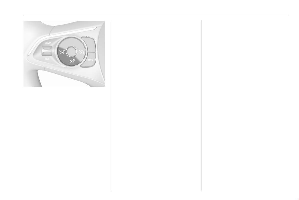
Driving and operating 191
Press i to activate speed limiter.
Adopting speed by the speed limit
recognition
A detected speed limit can be used as
new value for the speed limiter.
If the speed limiter is active, MEM
illuminates if the difference between
set speed and speed limit is more
than 6 mph.
Press MEM on the steering wheel to
request saving of the suggested
speed limit.
Press MEM on the steering wheel
once more to confirm and save the
new speed setting.
The function can be activated or
deactivated in the vehicle
personalisation 3 81.
Traffic sign assistant 3 220.
Exceeding the speed limit
In the event of an emergency, it is
possible to exceed the speed limit by
depressing the accelerator pedal
firmly to the final point. In this case,
the preset speed value flashes.
Release the accelerator pedal and
the speed limiter function is
reactivated once a speed lower than
the limit speed is obtained.
Deactivation of the functionality
Press i, speed limiter is in pause
mode and a message is displayed.
The vehicle is driven without speed
limiter.
Speed limiter is deactivated, but not
switched off. Last stored speed
remains in memory for later speed
resume.
Resume limit speed
Press i, the stored speed limit will
be obtained.
Switching off the system
Press 5, the speed limiter mode is
deselected and the speed limit
indication extinguishes in the Driver
Information Centre.
Pressing v to activate cruise control
deactivates speed limiter.
The preset speed remains in the
memory when the ignition is switched
off.
Fault
In the event of a speed limiter fault,
the speed is cleared resulting in
flashing of the dashes.
The speed limit recognition may not
operate correctly if traffic signs do not
comply with the Vienna Convention
on Road Signs and Signals.
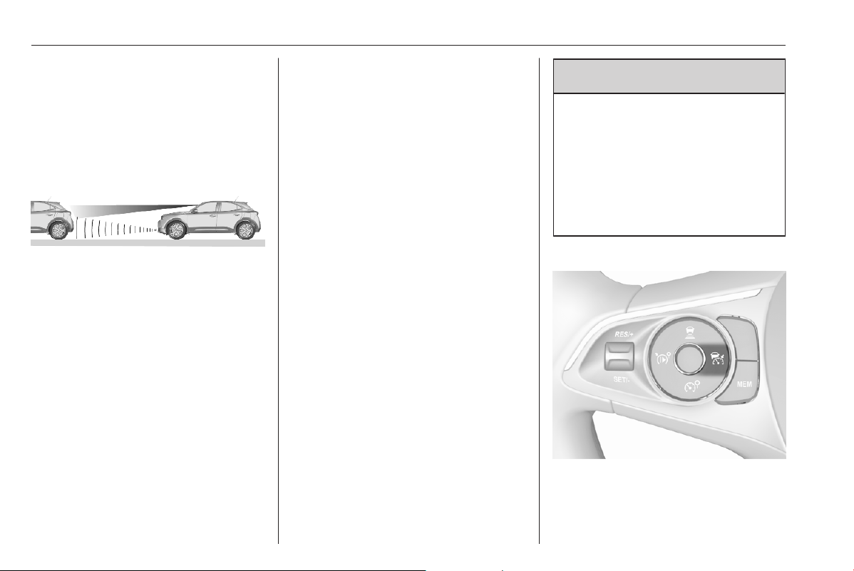
192 Driving and operating
Adaptive cruise control
The adaptive cruise control is an
enhancement of the cruise control
with the additional feature of
maintaining a certain following
distance to the vehicle ahead.
It uses radar and camera sensors to
detect the vehicles ahead. If no
vehicle is detected in the driving path,
the adaptive cruise control will
behave like a conventional cruise
control.
The adaptive cruise control
automatically decelerates the vehicle
when approaching a slower moving
vehicle. It then adjusts the vehicle
speed to follow the vehicle ahead at
the selected following distance. The
vehicle speed increases or decreases
to follow the vehicle ahead, but will
not exceed the set speed. It may
apply limited braking with activated
brake lights.
If the vehicle ahead accelerates or
changes lane, the adaptive cruise
control progressively accelerates the
vehicle to return to the stored set
speed. If the driver operates the turn
lights to overtake a slower vehicle, the
adaptive cruise control allows the
vehicle to temporarily approach the
vehicle ahead to help passing it.
However, the set speed will never be
exceeded.
The adaptive cruise control can store
set speeds over 18 mph for manual
transmission. If the vehicle ahead is
moving too slowly and the selected
following distance cannot be
maintained anymore, a warning
chime is given and a message is
displayed in the Driver Information
Centre. The message prompts the
driver to take back control of the
vehicle. On vehicles with automatic
transmission, the system can brake
the vehicle until a full stop. Depending
on variant, the system can
automatically accelerate the vehicle
after a full stop.
9
Warning
The complete driver attention is
always required while driving with
adaptive cruise control. The driver
stays fully in control of the vehicle
because the brake pedal, the
accelerator pedal and the button
Ñ have priority over any adaptive
cruise control operation.
Switching on the system
Press w.
w is indicated in the Driver
Information Centre. The system is still
not active.

Driving and operating 193
Activation of the functionality
Setting speed by the driver
The adaptive cruise control has to be
switched on manually at a speed
between 18 mph and 112 mph. For
vehicles with automatic transmission,
the automatic selector lever must be
in position D or M.
Accelerate to the desired speed and
move the thumb wheel to SET/-. The
current speed is stored and
maintained.
The speed value is indicated in the
Driver Information Centre.
The preset speed can then be
changed by moving thumb wheel to
RES/+ to increase or SET/- to
decrease the speed. Move thumb
wheel repeatedly to change speed in
small steps, move and hold to change
speed in large steps.
When the adaptive cruise control is
operating, the stop-start system is
automatically deactivated.
Adopting speed by the speed limit
recognition
A detected speed limit can be used as
new value for the adaptive cruise
control.
If the adaptive cruise control is active,
MEM illuminates if the difference
between set speed and speed limit is
more than 6 mph.
Press MEM on the steering wheel to
request saving of the suggested
speed.
Press MEM on the steering wheel
once more to confirm and save the
new speed setting.
The function can be activated or
deactivated in the vehicle
personalisation 3 81.
Traffic sign assistant 3 220.
Overriding set speed
It is always possible to drive faster
than the selected set speed by
depressing the accelerator pedal.
When the accelerator pedal is
released, the vehicle returns to the
stored speed. If a slower moving
vehicle is ahead, the following
distance selected by the driver is
restored.
If the set speed is exceeded, the
indicated speed setting disappears
and a warning message is displayed.
9 Warning
Accelerating by the driver
deactivates automatic braking by
the system. This is indicated as a
pop-up warning in the Driver
Information Centre.
Resuming stored speed
Move the thumb wheel to RES/+ at a
speed above 25 mph. The adaptive
cruise control is activated with the
stored set speed.

194 Driving and operating
Adaptive cruise control on
vehicles with automatic
transmission
For vehicles with automatic
transmission, adaptive cruise control
allows to maintain the selected
distance behind a braking vehicle
until a complete stop is reached.
If the system has stopped your
vehicle behind another vehicle, then
the set speed is replaced by a green
control indicator .. This symbol
notifies, that the vehicle is hold
automatically in stop position.
When the vehicle ahead drives away
within some seconds and the traffic
conditions allow a restart of the
vehicle, then active cruise control is
resumed automatically.
If the stopped vehicle ahead was
stopped for a longer time and then
begins to move forward, the green
control indicator . will flash and a
warning chime will sound as a
reminder to check traffic before
resuming.
When the vehicle ahead drives away,
depress the accelerator pedal or
press i to resume adaptive cruise
control.
If the vehicle stays stopped for more
than 5 minutes or if the driver's door
is opened and the driver's seat belt is
unfastened, then the electric parking
brake is applied automatically to hold
the vehicle. Control indicator j will
illuminate. To release electric parking
brake, press the accelerator pedal.
Electric parking brake 3 183.
9 Warning
When the system is deactivated or
cancelled, the vehicle will no
longer be held at a stop and can
start moving. Be always prepared
to manually apply the brake to hold
the vehicle stationary.
Do not leave the vehicle while it is
being held at a stop by adaptive
cruise control. Always move
selector lever to park position P
and switch off the ignition before
leaving the vehicle.
Setting the following distance
When adaptive cruise control detects
a slower moving vehicle in the driving
path, it will adjust the vehicle speed to
maintain the following distance
selected by the driver.
The following distance can be set to
close (1 bar), normal (2 bars) or far (3
bars).
If the engine is running and the
adaptive cruise control is enabled
(grey) or active (green), you can
modify the following distance setting:
Press V, the current setting is
shown in the Driver Information
Centre.
Press V again to change the
following distance: The new setting is
displayed in the Driver Information
Centre.
The selected following distance is
indicated by full bars in the adaptive
cruise control page.
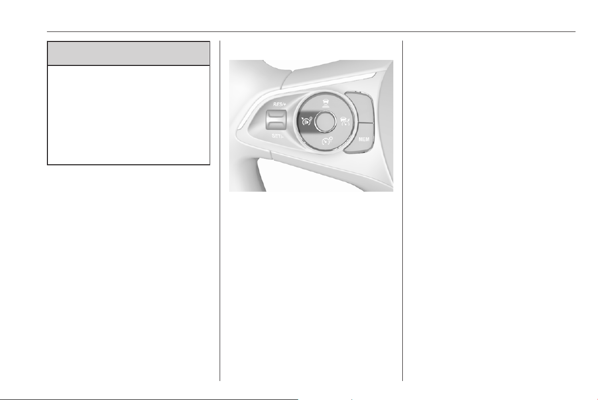
Driving and operating 195
9 Warning
The driver accepts full
responsibility for the appropriate
following distance based on traffic,
weather and visibility conditions.
Following distance must be
adjusted or the system switched
off when required by the prevailing
conditions.
Detecting the vehicle ahead
If the system detects a vehicle in the
driving path, the adaptive cruise
control symbol displayed in the Driver
Information Centre changes from -
to w.
Deactivation of the functionality
Press i, the adaptive cruise control
is in pause mode and a message is
displayed. The vehicle is driven
without adaptive cruise control.
The adaptive cruise control is
deactivated, but not disabled. The
last stored set speed remains in
memory for later usage.
The adaptive cruise control is
deactivated automatically in the
following cases:
● The brake pedal is depressed.
● The vehicle accelerates above
112 mph (manual and automatic
transmission) or slows down
below 25 mph (manual
transmission).
● The electric parking brake is
applied.
● The traction control system or
electronic stability control is
deactivated or operating.
● The selector lever of automatic
transmissions is neither in D nor
in M.
● A fault is detected in the
electronic stability control, the
radar system or the camera
system.
● Immediately after the clutch
pedal has been depressed or a
few seconds after the clutch
pedal has been depressed
(depending on the manual
transmission).
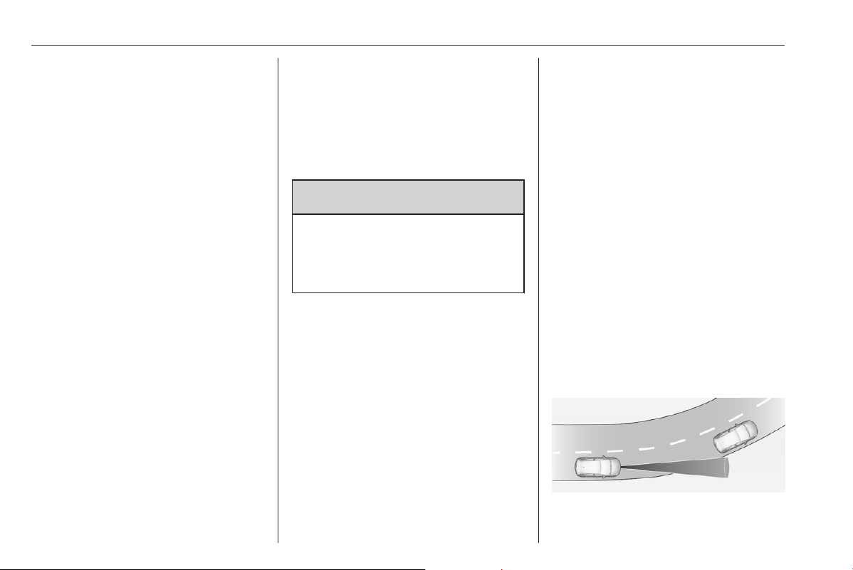
196 Driving and operating
Switching off the system
Press w, the adaptive cruise control
mode is disabled and the adaptive
cruise control indication extinguishes
in the Driver Information Centre.
Pressing 5 to activate the speed
limiter deactivates adaptive cruise
control.
Switching off the ignition deletes the
stored set speed.
Driver's attention
● Use the adaptive cruise control
carefully on bends or mountain
roads, as it can lose the vehicle
ahead and needs time to detect it
again.
● Do not use the system on
slippery roads as it can create
rapid changes in tyre traction
(wheel spinning), so that you
could lose control of the vehicle.
● Do not use the adaptive cruise
control during rain, snow or
heavy dirt, as the radar sensor
can be covered by a water film,
dust, ice or snow. This reduces or
suppresses completely the
visibility. In case of sensor
blockage, clean the sensor
cover.
● Do not use the system when the
spare wheel is in use.
System limits
9 Warning
The system's automatic brake
force does not permit hard braking
and the braking level may not be
sufficient to avoid a collision.
● After a sudden lane change, the
system needs a certain time to
detect the next preceding
vehicle. So if a new vehicle is
detected, the system may
accelerate instead of braking.
● The adaptive cruise control only
considers traffic driving in the
same direction.
● The adaptive cruise control does
not consider pedestrians and
animals for braking and driving
off.
● The adaptive cruise control
considers stopped vehicles only
at low speed.
● Do not use the adaptive cruise
control when towing a trailer.
● Do not use the adaptive cruise
control on roads with an incline of
more than 10%.
As the radar's field of detection is
quite narrow, it is possible that the
system may not detect:
● vehicles of reduced width, e.g.
motorcycles, scooters
● vehicles not running in the middle
of the lane
● vehicles entering a corner
● vehicles suddenly pulling out
Bends
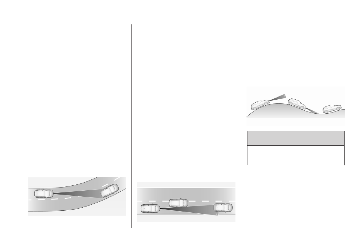
Driving and operating 197
The adaptive cruise control calculates
a predicted path based on the
centrifugal force. This predicted path
considers the current bend
characteristic, but cannot consider a
future bend change. The system may
lose the current vehicle ahead or
consider a vehicle which is not in the
actual lane. This can happen when
entering or exiting a bend or if the
bend gets stronger or weaker. If it no
longer detects any vehicle ahead,
then w will extinguish.
If the centrifugal force is too high in a
bend, the system slows down the
vehicle slightly. This braking level is
not designed to avoid spinning-off the
bend. The driver is responsible for
reducing the selected speed before
entering a bend and in general to
adapt the speed to the road type and
to existing speed limits.
Motorways
On motorways, adapt the set speed
to the situation and the weather.
Always consider that adaptive cruise
control has a limited visibility range, a
limited braking level and a certain
reaction time to verify if a vehicle is on
the driving path or not. Adaptive
cruise control may not be able to
brake the vehicle in time to avoid a
collision with a much slower vehicle or
after a lane change. This is
particularly true while driving fast or if
the visibility is reduced due to weather
conditions.
While entering or exiting a motorway,
adaptive cruise control may lose the
vehicle ahead and accelerate up to
the set speed. For this reason,
decrease the set speed before the
exit or before the entry.
Vehicle path changes
If another vehicle enters your driving
path, adaptive cruise control will first
consider the vehicle when it is
completely in your path. Be ready to
take action and depress the brake
pedal if you need to brake more
quickly.
Hill considerations
9 Warning
Do not use the adaptive cruise
control on steep hill roads.
System performance on hills depends
on vehicle speed, vehicle load, traffic
conditions and the road gradient. It
may not detect a vehicle in your path
while driving on hills. On steep hills,
you may have to use the accelerator
pedal to maintain your vehicle speed.
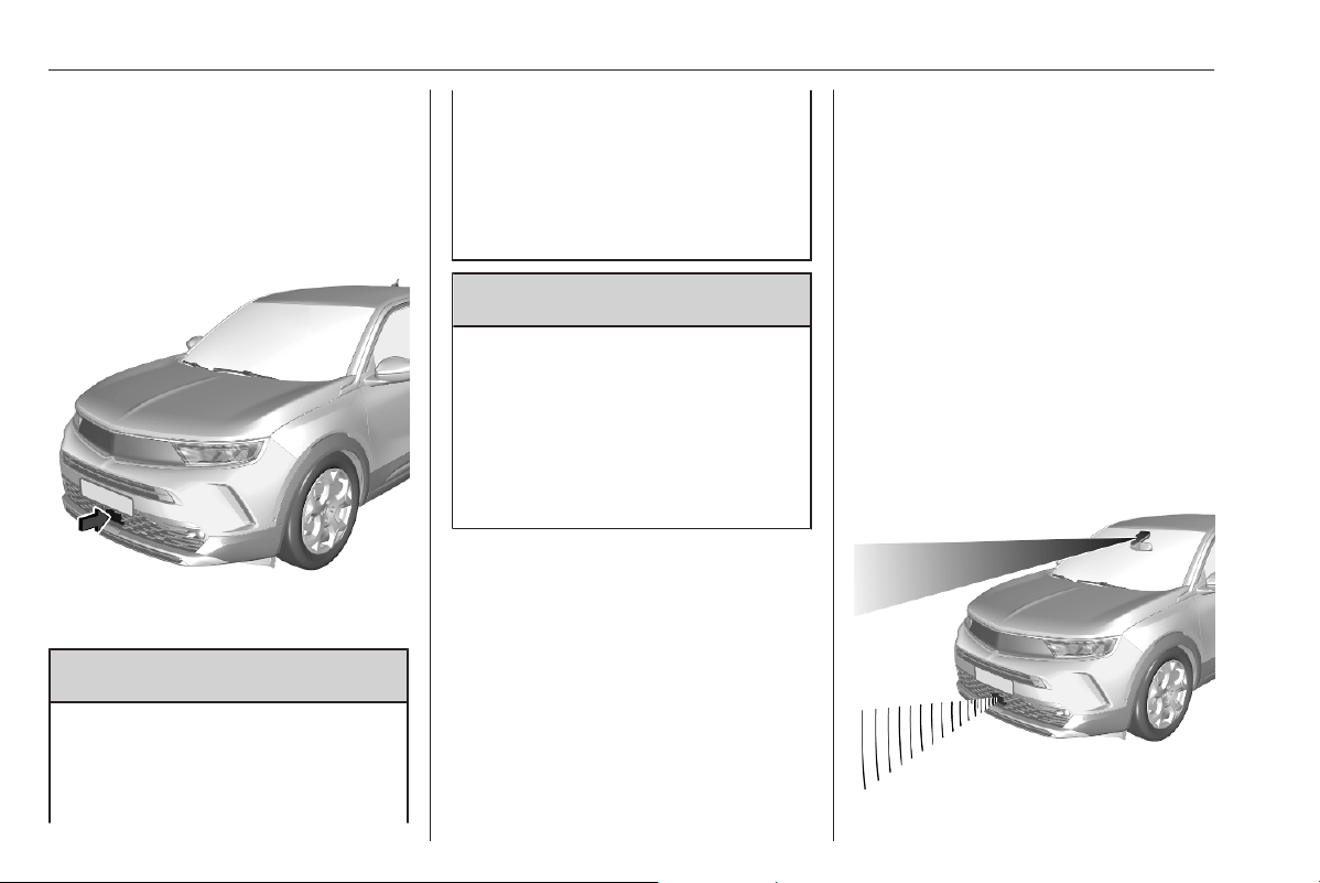
198 Driving and operating
When going downhill you may have to
brake to maintain or reduce your
speed.
Note that applying the brake
deactivates the system.
Radar unit
The radar unit is located in the middle
of the front bumper.
9 Warning
The radar unit was aligned
carefully during manufacture.
Therefore, in the event of a front-
end impact, do not use the system.
The front bumper may appear to
be intact, however the sensor
behind may be affected and react
incorrectly. After an accident,
consult a workshop to verify and
adjust the radar unit position.
9 Warning
The usage of a license plate
support on the front bumper may
affect the proper radar unit
functionality.
When using a license plate
support, follow the markings and
indications on the front bumper.
Fault
In the event of an adaptive cruise
control fault, a warning light is
illuminated in the Driver Information
Centre and a warning message is
displayed in the Driver Information
Centre accompanied by an audible
signal.
The speed limit recognition may not
operate correctly if traffic signs do not
comply with the Vienna Convention
on Road Signs and Signals.
Have the system checked by a dealer
or a qualified workshop.
As a safety measure, do not use the
system if the brake lights are faulty.
Do not use the system if the front
bumper is damaged.
Forward collision alert
The forward collision alert may help to
avoid or reduce the harm caused by
front-end crashes.

Driving and operating 199
The forward collision alert uses the
front camera in the windscreen and
depending on the vehicle
configuration a radar unit located
behind the front bumper to detect a
vehicle directly ahead, in the path.
If a vehicle directly ahead is
approached too quickly, a warning
chime sounds and a message is
displayed in the Driver Information
Centre.
9 Warning
Forward collision alert is just a
warning system and does not
apply the brakes. When
approaching a vehicle ahead too
rapidly, it may not provide you
enough time to avoid a collision.
The driver accepts full
responsibility for the appropriate
following distance based on traffic,
weather and visibility conditions.
The complete attention of the
driver is always required while
driving. The driver must always be
ready to take action and apply the
brakes.
Activation
The forward collision alert operates
from 3 mph to vehicle's maximum
speed.
Alerting the driver
The driver is warned by following
alerts:
● A warning message is displayed
in the Driver Information Center,
when the distance to the vehicle
ahead gets too small.
● A warning message is displayed
in the Driver Information Center
and a warning chime sounds,
when a collision is imminent and
immediate driver's action is
required.
● In some cases, the system
performs a short braking, when a
collision is imminent and
immediate driver's action is
required.
Selecting the alert sensitivity
Three alert sensitivities can be
selected in the settings of the active
emergency braking within the vehicle
personalisation 3 81.
The chosen setting will be memorised
when the ignition has been switched
off. The alert timing will vary based on
selected alert setting.
Deactivation
The system can only be deactivated
by deactivating the active emergency
braking in the vehicle personalisation
3 81. When ignition is switched on
next time, system is activated.
System limitations
Forward collision alert is designed to
warn on vehicles, pedestrians and
cyclists, but may react also to other
objects.

200 Driving and operating
In the following cases, forward
collision alert may not detect a vehicle
ahead or sensor performance is
limited:
● driving on winding or hilly roads
● driving during nighttime
● weather limits visibility, such as
fog, rain, or snow
● the sensor in the windscreen or
the radar unit behind the front
bumper are blocked by snow, ice,
slush, mud, dirt etc.
● the windscreen is damaged or
affected by foreign objects, e.g.
stickers
● the bumper is damaged or
affected by foreign objects, e.g.
license plate support
Active emergency braking
Active emergency braking can help to
reduce the damage and injury from
crashes with vehicles and
pedestrians directly ahead, when the
driver does not actively take action
either by manual braking or by
steering. For vehicles equipped with
camera and radar, active emergency
braking also detects cyclists. Before
the active emergency braking
applies, the driver is warned by the
forward collision alert.
Forward collision alert 3 198.
Front pedestrian protection 3 204.
Active emergency braking can be
deactivated in the vehicle
personalisation 3 81. Depending on
version, this is only possible at a
standstill. If deactivated, m
illuminates in the Driver Information
Centre. When ignition is switched on
next time, system is automatically
activated.
The feature uses various inputs (e.g.
camera sensor, radar sensor) to
calculate the probability of a frontal
collision.
9 Warning
This system is not intended to
replace the driver's responsibility
for driving the vehicle and looking
ahead. It warns the driver if the
vehicle is at risk of a collision with
the preceding vehicle, a
pedestrian or a cyclist. Just before
the imminent collision, it reduces
the vehicle's speed to avoid a
collision or to limit its severity.
The system may not react to
animals. After a sudden lane
change, the system needs a
certain time to detect the next
preceding vehicle.
The driver must always be ready
to take action and apply the brakes
and steer to avoid collisions.
Functionality
Depending on the vehicle
configuration and the detected
objects, there are several operational
speed ranges.
Active emergency braking operates
up to 50 mph when a pedestrian has
been detected.
On vehicles equipped with radar
sensor and front camera, the active
emergency braking operates up to
50 mph when a stationary vehicle or
a cyclist has been detected.

Driving and operating 201
On vehicles equipped only with front
camera, the active emergency
braking operates from 3 mph to
50 mph or 87 mph when a moving
vehicle has been detected.
On vehicles equipped with radar
sensor and front camera, the active
emergency braking operates from
3 mph to 87 mph when a moving
vehicle has been detected.
The system includes:
● brake preparation system
● emergency automatic braking
● smart brake assist
● forward collision alert
● front pedestrian protection
Brake preparation system
When approaching a vehicle ahead
or a pedestrian so quickly that a
collision is likely, the brake
preparation system slightly
pressurises the brakes. This reduces
the response time, when braking is
requested.
The pressurisation of the brakes may
produce a noise in the brake system.
Emergency automatic braking
After activation of brake preparation
system and just before the imminent
collision, this function automatically
applies braking to reduce the impact
speed of the collision or prohibit a
crash.
If active emergency braking is
applied, m flashes in the Driver
Information Centre. If active
emergency braking is finished, m
flashes for a few seconds. During this
time, active emergency braking
cannot be applied if there is a risk of
a further collision.
Forward collision alert 3 198.
Front pedestrian protection 3 204.
Depending on version, below a speed
of 19 mph or 31 mph, emergency
automatic braking may slow down the
vehicle to a complete stop. If the
speed exceeds this limit, emergency
automatic braking reduces the speed.
However, the driver must apply the
brake to come to a complete stop.
● Automatic transmission: If the
vehicle comes to a complete
stop, automatic braking is
maintained for a certain time.
Keep the brake pedal depressed
to prevent the vehicle from
starting off again.
● Manual transmission: If the
vehicle comes to a complete
stop, the engine may stall. Keep
the brake pedal depressed to
prevent the vehicle from rolling
away.
Cruise control and adaptive cruise
control will be deactivated when an
emergency automatic braking occurs.
In some cases, the active emergency
braking system may provide an
automatic braking in situations that
seem to be unnecessary. Firmly apply
the accelerator pedal or firmly turn the
steering wheel to override the
automatic braking if the situation and
the surroundings permit.
9 Warning
Do not rely on the system to brake
the vehicle. Emergency automatic
braking is only applied just before
the collision and it will not brake

202 Driving and operating
outside of its operating speed
range. It only responds to detected
vehicles and pedestrians. For
vehicles equipped with camera
and radar, it also responds to
detected cyclists.
Antilock brake system 3 182.
Smart brake assist
If the driver brakes, but not sufficiently
to avoid a collision, this system will
supplement the braking. This
assistance will only be provided if the
driver presses the brake pedal.
Smart brake assist will automatically
disengage when the brake pedal is
released.
Forward collision alert 3 198.
Front pedestrian protection 3 204.
Operation conditions
Active emergency braking only works
when
● the seat belts of the front seats
and depending on version of the
rear seats are fastened
● the brake system is operational
● Electronic Stability Control and
Traction Control system are
activated
Active emergency braking is
automatically deactivated in the
following cases:
● A spare wheel with smaller
diameter is detected.
● A fault with the brake pedal
switch or with the left or right
brake light is detected.
● A fault in the active emergency
braking system, in the electronic
or in the brake system is
detected.
● A severe crash, e.g., with airbag
deployment was detected.
System limitations
The system performance may be
degraded or not available in the
following cases:
● sensor covered with snow, ice,
slush, mud or dirt
● windscreen damaged or
smeared, with blurred view or
covered with foreign items, e.g.
stickers,
● damaged or deformed front
bumper or front bumper covered
with foreign items, e.g. stickers
● radar unit is out of its regular
position resulting from an impact
of the front bumper
● front camera out of its regular
position
● automatic braking not available,
e.g. brake discs cooling going on
● brake pedal continuously used
for a long time, e.g. on a long
downhill road
● winding or hilly roads
● during initialisation of the system,
e.g. after the vehicle battery has
been disconnected

Driving and operating 203
● sun or lights shining into the front
camera lens
● adverse environmental
conditions, e.g. rain, fog, or snow
● vehicle ahead creating road
spray
After an impact or when damages are
visible have the vehicle checked by a
workshop.
The system performance may be
affected by:
● electronic stability control and
traction control system in
operation
● vehicle battery out of normal
operation voltage
● wet road reflecting lights
● close vehicles ahead
● tractors, muddy vehicles or
vehicles with a trailer
● banked roads
● poor lighting conditions
● sudden lighting changes
● vehicle modifications, e.g. tyres
● vehicle overloaded
If a sensor is covered, a message is
displayed indicating that the sensors
have to be cleaned.
If the system is temporarily affected
and no driver action is required, no
message is displayed.
Complete attention is always required
while driving, and be ready to take
action to avoid crashes.
We recommend to deactivate the
system in the vehicle personalisation
in the following cases:
● when towing a trailer or caravan
● when carrying long objects on
roof bars or a roof rack
● when the vehicle is being towed
● when performing any
maintenance with ignition on
● when the vehicle is fitted with
snow chains
● when a spare wheel is fitted that
is smaller than the other wheels
● before using an automatic car
wash
● before placing the vehicle on a
rolling road in a workshop
● if the windscreen has been
damaged close to the camera
● if the front bumper has been
damaged or deformed
● if the radar unit is out of its regular
position resulting from an impact
of the front bumper
● if the brake lights are not working
Fault
If the system has a fault, m
illuminates in the Driver Information
Centre, a message is displayed and
an audible signal is given. Consult a
workshop.
If the system does not work properly
or is not available, e.g. during the
initialisation, m illuminates in the
Driver Information Centre.
If m and C illuminate in the Driver
Information Centre after the engine
has been switched off and then
restarted, consult a workshop.
Vehicle messages 3 80.
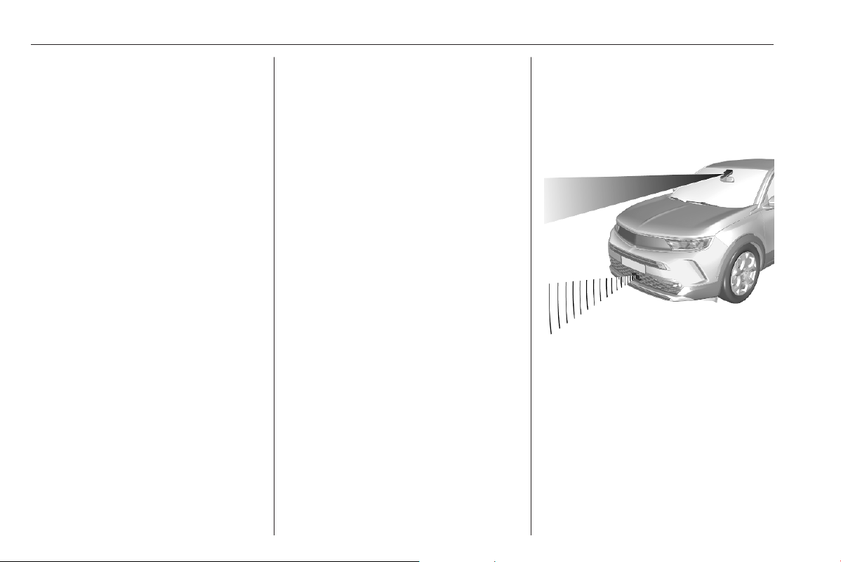
204 Driving and operating
Automatic post collision
braking
If an accident is detected, the vehicle
requests automatic post collision
braking. The goal of this function is to
reduce the risk of further collisions if
the driver does not react. The
automatic post collision braking is not
operational if the capability of the
vehicle to trigger and execute the
automatic post collision braking is
unavailable, as it can occur in
destructive accidents or in other
specific accident scenarios.
It is possible to override the automatic
braking by pressing the accelerator
pedal or the brake pedal.
System limitations
The system operates if the following
conditions are fulfilled:
● airbags or seat belt pretensioners
have been deployed by the
collision
● braking system and electric
functions remain continuously
operational during and after
collision
● driver has not depressed brake
pedal or accelerator pedal
Fault
If automatic post collision braking is
not available, the control indicator J
or d illuminates continuously, a
corresponding message appears in
the Driver Information Centre and a
warning chime sounds.
Have the cause of the fault remedied
by a workshop.
Front pedestrian protection
Front pedestrian protection may help
to avoid or reduce the harm caused
by front-end crashes with pedestrians
when driving forward.
The system uses the front camera in
the windscreen and depending on the
vehicle configuration a radar unit in
the front bumper to detect a
pedestrian directly ahead in the path.
Driving and operating 205
9 Warning
The usage of a license plate
support on the front bumper may
affect the proper radar unit
functionality.
When using a license plate
support, follow the markings and
indications on the front bumper.
Front pedestrian protection can
detect and alert to pedestrians in a
forward gear at speeds between
3 mph and 50 mph. Additionally, it can
automatically brake the vehicle.
During nighttime driving, system
performance is limited.
9 Danger
Front pedestrian braking does not
provide an alert or automatically
brake the vehicle, unless it detects
a pedestrian.
The system may not detect
pedestrians, including children,
when the pedestrian is not directly
ahead, not fully visible, not
standing upright, or when part of a
group.
The system can only be deactivated
by deactivating the active emergency
braking in the vehicle personalisation
3 81. When ignition is switched on
next time, system is activated.
Front pedestrian alert
When approaching a detected
pedestrian too quickly, a warning
message is displayed in the Driver
Information Centre. A warning chime
is provided.
Cruise control or adaptive cruise
control may be disengaged when the
front pedestrian alert occurs.
System limitations
In the following cases, front
pedestrian protection may not detect
a pedestrian ahead or sensor
performance is limited:
● driving on winding or hilly roads
● driving in the dark
● weather limits visibility, such as
fog, rain, or snow
● the sensor in the windscreen or
the radar unit behind the front
bumper is blocked by snow, ice,
slush, mud, dirt or by foreign
objects, e.g. stickers
● the windscreen is damaged
● the bumper is damaged
Parking assist
General information
The rear system is deactivated when
a plug is connected to the power
outlet of the trailer hitch.
9 Warning
The driver bears full responsibility
for the parking manoeuvre.
Always check the surrounding
area when driving backwards or
forwards while using parking
assist system.
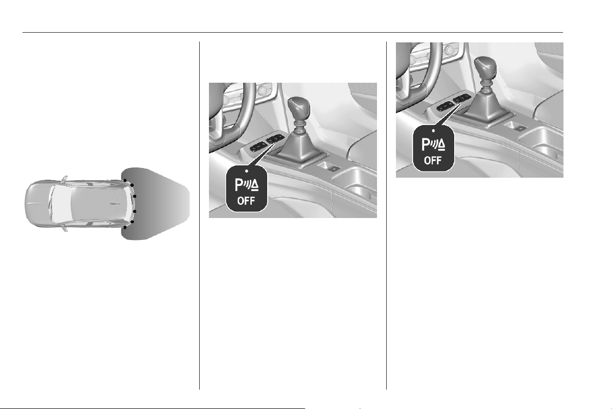
206 Driving and operating
Rear parking assist
The system warns the driver with
audible signals and a display
indication against potentially
hazardous obstacles behind the
vehicle while the reverse gear is
engaged.
The system operates with ultrasonic
parking sensors in the rear bumper.
Activation
After engaging the reverse gear, an
audible signal is given from the rear
speakers and a display indication will
be shown. If no audible signal is
given, the display indication is not
shown or a warning message
appears, the system has a failure.
Depending on version the system is
ready to operate when the LED in the
parking assist button e is not
illuminated. The state of the system is
memorised when the ignition is
switched off.
Deactivation
The system is switched off when
reverse gear is disengaged.
Press e to deactivate the system
manually. The LED in the button
illuminates when the system is
deactivated. If the system has been
deactivated manually, it is not
reactivated automatically the next
time the ignition is switched on.
Indication
As soon as an obstacle gets closer to
the vehicle, an audible signal is given
and the symbol 1 may flash. The
interval between the sounds
becomes shorter as the vehicle gets
closer to that obstacle. When the
distance is less than approx. 30 cm,
the sound is continuous.
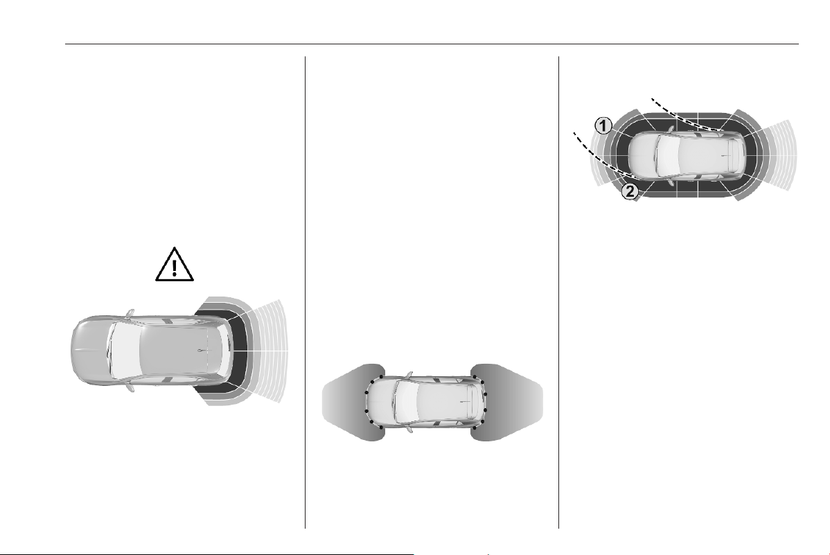
Driving and operating 207
If the vehicle stops for more than
three seconds, if the automatic
transmission is in P position, or if no
further obstacles are detected, no
audible signals are given.
Notice
An audible signal is not given if the
sound has been muted or if the
display of the rear view camera
indicated on the Info Display has
been switched off.
Additionally, the distance to rear
obstacles is displayed by changing
distance lines in the Info Display
3 78. When the obstacle is very close,
+ for danger is displayed.
Muting the sound / closing the display
indication
If the audible signal is muted or the
display of the rear view camera is
closed and an obstacle gets closer,
only the 1 flashes.
When engaging the forward gear and
driving more than 6 mph the sound
and the display are automatically
resumed.
Front-rear parking assist
The front-rear parking assist
measures the distance between the
vehicle and obstacles in front and
behind the vehicle. It informs and
warns the driver by giving audible
signals and a display indication.
The system operates with ultrasonic
parking sensors in the rear and front
bumper.
If the obstacle (1) is within the driving
path and might lead to a collision, an
audible signal is given.
The interval between the sounds
becomes shorter as the vehicle gets
closer to the obstacle in the driving
path. When the distance is less than
approx. 30 cm, the sound is
continuous.
Obstacles (2) that are close to the
vehicle, but not within the calculated
driving path are indicated in the Info
Display, but no audible signal is
given.
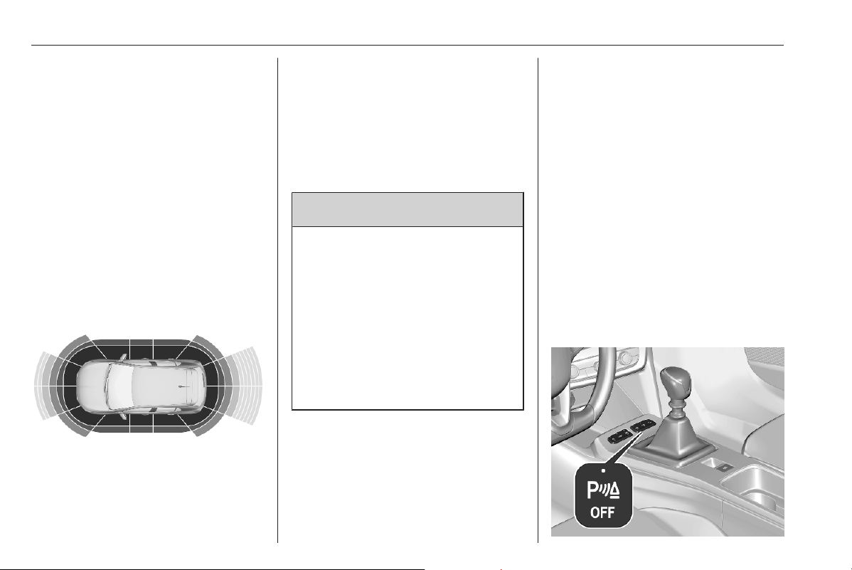
208 Driving and operating
The distance to rear, front and lateral
obstacles is displayed by changing
distance lines in the Info Display
3 78.
If the vehicle stops for more than
three seconds in a forward gear, if the
automatic transmission is in P
position, the vehicle speed exceeds
6 mph or if no further obstacles are
detected, no audible signals are given
and no visual feedback is displayed in
the Info Display.
Side protection
This function warns the driver by
display indication in the case of
obstacles alongside the vehicle. If the
obstacle is alongside the vehicle and
within the driving path and might lead
to a collision, an audible signal is
given. Obstacles alongside the
vehicle are only considered if they
have been previously recognised by
the parking sensors and memorised
by the system.
9 Warning
Only fixed obstacles are indicated
correctly.
Moving obstacles detected at the
beginning of a manoeuvre may be
indicated mistakenly.
Moving obstacles that appear
alongside the vehicle and were not
previously recognised by the
parking sensors will not be
indicated.
Objects memorised during the
manoeuvre will only be considered
during the current ignition cycle.
Activation
When a forward gear has been
engaged, the front parking assist is
triggered, as soon as an obstacle is
detected in the front and the speed of
the vehicle is below 6 mph.
When the reverse gear has been
engaged, the front parking assist is
triggered additionally to the rear
parking assist.
After engaging the reverse gear, an
audible signal is given from the rear
speakers and a display indication will
be shown. If no audible signal is
given, the display indication is not
shown or a warning message
appears, the system has a failure.
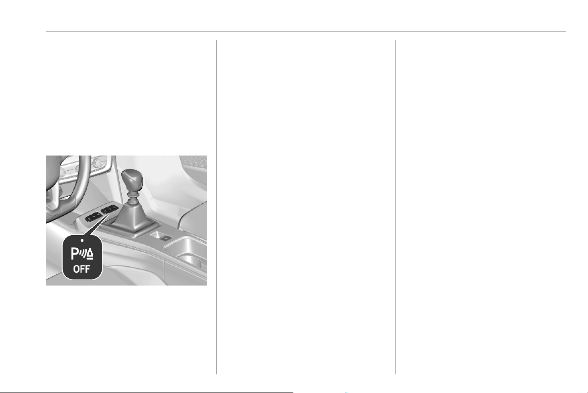
Driving and operating 209
Depending on version the system is
ready to operate when the LED in the
parking assist button e is not
illuminated. The state of the system is
memorised when the ignition is
switched off.
Deactivation
The system is switched off when
reverse gear is disengaged.
Press e or apply the electric parking
brake to deactivate the system
manually. When the system is
deactivated manually, the LED in the
button illuminates. If the system has
been deactivated manually, it is not
reactivated automatically the next
time the ignition is switched on.
Indication
As soon as an obstacle gets closer to
the vehicle, an audible signal is given
and the symbol 1 may flash. The
interval between the sounds
becomes shorter as the vehicle gets
closer to that obstacle. When the
distance is less than approx. 30 cm,
the sound is continuous.
Audible signals are given via front or
rear loudspeakers depending on
which detected obstacle is nearest to
the vehicle.
If the vehicle stops for more than
three seconds, if the automatic
transmission is in P position, or if no
further obstacles are detected, no
audible signals are given.
Notice
An audible signal is not given if the
sound has been muted or if the
display of the rear view camera
indicated on the Info Display has
been switched off.
Additionally, the distance to obstacles
is displayed by changing distance
lines in the Info Display 3 78. When
the obstacle is very close, + for
danger is displayed.
Muting the sound / closing the display
indication
If the audible signal is muted or the
display of the rear view camera is
closed and an obstacle gets closer,
only the 1 flashes.
When engaging the forward gear and
driving more than 6 mph the sound
and the display are automatically
resumed.
System limitations
In the event of a fault or if the system
does not work temporarily, e.g.
because of high external noise level
or other interference factors, C
illuminates in the Driver Information
Centre. A message is displayed in the
Driver Information Centre and a
warning chime sounds.
In the case of a permanent fault, seek
the assistance of a workshop.

210 Driving and operating
9 Warning
Under certain circumstances,
various reflective surfaces on
objects or clothing as well as
external noise sources may cause
the system to fail to detect
obstacles.
Special attention must be paid to
low obstacles which can damage
the lower part of the bumper.
Caution
In the case of a severe failure of
the vehicle with the need to stop
the vehicle, the system is
deactivated.
In the case of a gearbox failure,
the parking assist system is not
active, when reverse gear is
engaged.
In the case of a loudspeaker
failure, the audible signals may not
be given.
Performance of the system can be
reduced when sensors are
covered, e.g. by ice or snow.
If a sensor is covered, a message
is displayed indicating that the
sensors have to be cleaned.
Performance of the parking assist
system may be limited or the
functionality may not be available
at all if C illuminates or if the
image shown on the Info Display
is frozen or if the screen is black.
Performance of the parking assist
system can be reduced due to
heavy loading.
Special conditions apply if there
are taller vehicles in the vicinity
(e.g. off-road vehicles, mini vans,
vans). Object identification and
correct distance indication in the
upper part of these vehicles
cannot be guaranteed.
Objects with a very small reflection
cross-section, e.g. objects of
narrow size or soft materials, may
not be detected by the system.
Parking assist systems do not
detect objects outside the
detection range, e.g. below the
bumper or underneath the vehicle.
During a reverse parking
manoeuvre, the system does not
consider a mounted coupling ball
bar. The driver has to consider this
additional length.
Notice
It is possible that the sensor detects
a non-existing object caused by
echo disturbance from external
acoustic noise or mechanical
misalignments (sporadic false
warnings may occur).
Make sure that the front number
plate is properly mounted (not bent
and no gaps to the bumper on the left
or right side) and the sensors are
firmly in place. The performance of
the parking assist may be reduced if
the license plate is bent or a license
plate support is used.
Low curbs and surface irregularities,
e.g. on construction zones, are not
detected by the system. The driver
accepts responsibility.
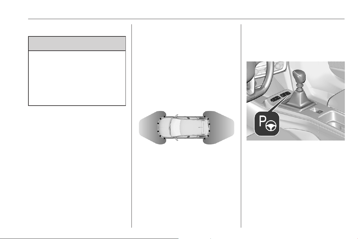
Driving and operating 211
Advanced parking assist
9 Warning
The driver bears full responsibility
for accepting the parking slot
suggested by the system and the
parking manoeuvre.
Always check the surrounding
area in all directions when using
the advanced parking assist.
The advanced parking assist
measures a suitable parking slot
while passing, calculates the
trajectory and automatically steers
the vehicle while parking.
Advanced parking assist provides
assistance for the following
manoeuvres:
● entry into a parallel parking slot
● entry into a perpendicular parking
slot
● exit from a parallel parking slot
The driver must control acceleration,
braking and gear shifting, while
steering is done automatically. The
driver can take control at any time by
gripping the steering wheel.
It may be necessary to move forwards
and backwards more than once.
Instructions are given in the Info
Display 3 78.
Advanced parking assist can only be
activated when driving forwards.
Advanced parking assist is always
combined with front-rear parking
assist.
The system has six ultrasonic parking
sensors each in both the rear and
front bumper.
Entry into a parallel parking slot
Activation
Slow down the vehicle speed below
19 mph.
Press
S or activate the system via
the Info Display.
Info Display 3 78.
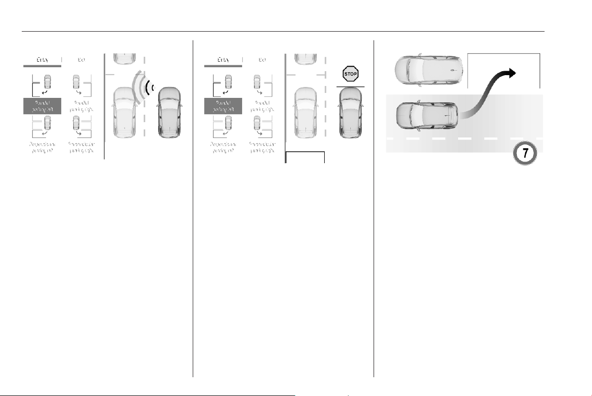
212 Driving and operating
Select the parallel parking slot menu.
S is illuminated in the Driver
Information Centre to confirm the
activation of the system.
The allowed parallel distance
between the vehicle and a row of
parked cars is between 0.5 m and
1.5 m.
The system will not identify slots that
are clearly smaller than the vehicle.
When a free slot is detected, a visual
feedback on the Info Display and a
first acoustic signal are given.
Drive slowly forwards. When the
second acoustic signal is given, stop
the vehicle, select reverse gear,
release the steering wheel and start
moving slowly. A visual feedback is
given on the Info Display.
Move forwards and backwards while
observing the warnings of the parking
assist until the end of manoeuvre is
indicated.
Entry into a perpendicular parking
slot
Activation
Slow down the vehicle speed below
19 mph.
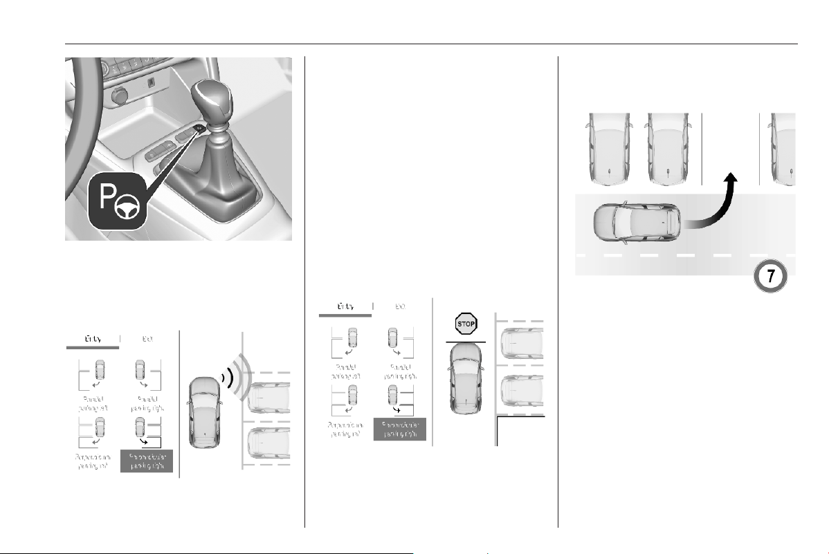
Driving and operating 213
Press S or activate the system via
the Info Display.
Info Display 3 78.
Select the perpendicular parking slot
menu. S is illuminated in the Driver
Information Centre to confirm the
activation of the system.
The allowed parallel distance
between the vehicle and a row of
parked cars is between 0.5 m and
1.5 m.
When several successive slots are
found, the vehicle will be directed
towards the last one.
The system will not identify slots that
are clearly smaller than the vehicle.
When a free slot is detected, a visual
feedback on the Info Display and an
acoustic signal are given. Stop the
vehicle, select reverse gear, release
the steering wheel and start moving
without exceeding 4 mph.
Move forwards and backwards as
instructed by observing the warnings
of the parking assist and paying
attention to the acoustic signals until
the end of manoeuvre is indicated.
During the parking manoeuvre, the
system is automatically deactivated
once the rear of the vehicle is within
50 cm of an obstacle.
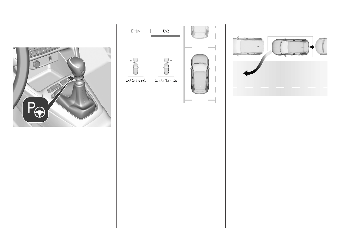
214 Driving and operating
Exiting a parallel parking slot
Activation
Press S or activate the system via
the Info Display.
Info Display 3 78.
Select the exit side in the menu. S is
illuminated in the Driver Information
Centre to confirm the activation of the
system.
Engage reverse or forward gear,
release the steering wheel and start
moving without exceeding 3 mph.
Move forwards and backwards while
observing the warnings of the parking
assist until the end of manoeuvre is
indicated.
The manoeuvre is complete when the
vehicle's front wheels are out of the
parking slot.
After deactivation ensure to take
control over the vehicle.
Display indication
The instructions on the display show:
● general hints and warning
messages
● the demand to stop the vehicle,
when a parking slot is detected

Driving and operating 215
● the direction of driving during the
parking manoeuvre
● the demand to shift into reverse
or first gear
● the demand to stop or to drive
slowly
● the successful completion of the
parking manoeuvre indicated by
a pop-up symbol and a chime
● the cancelling of a parking
manoeuvre
Deactivation
Do not use the advanced parking
assist when a temporary spare wheel
is mounted. The rear view camera
may not work properly.
The current park assist manoeuvre is
cancelled via the button to return to
the previous screen in the Info
Display. To deactivate the system
completely, press S in the centre
console.
The system is deactivated
automatically:
● if the ignition is switched off
● if stalling the engine
● if no manoeuvre is started within
5 minutes of selection of the type
of manoeuvre
● after a prolonged stop of the
vehicle during a manoeuvre
● activating the turn light on the
opposite side to that of the
manoeuvre
● if the electronic stability control is
triggered
● if the speed of the vehicle
exceeds the stated limit
● when the driver interrupts
movement of the steering wheel
● after ten manoeuvres to enter or
exit a parallel parking slot or after
seven manoeuvres to enter a
perpendicular parking slot
● by opening the driver's door
● if one of the front wheels
encounters an obstacle
● parking manoeuvre successfully
ended
Deactivation by the driver or by the
system during manoeuvring will be
indicated on the display. Additionally,
a chime sounds.
The system is deactivated when a
plug is connected to the power outlet
of the trailer hitch.
Contact your dealer to switch off the
system for a prolonged period.
Fault
In the event of a fault, a message is
displayed in the Colour Info Display,
accompanied by an acoustic signal.
In the event of a fault in the power
steering, C illuminates and a
message is displayed in the Driver
Information Centre.
Notice
Advanced parking assist system
may not respond to changes in the
available parking space after
initiating a parking manoeuvre. The
system may recognize an entry, a
gateway, a courtyard or even a
crossing as a parking slot. Take care
regarding the availability of the
suggested parking slot.
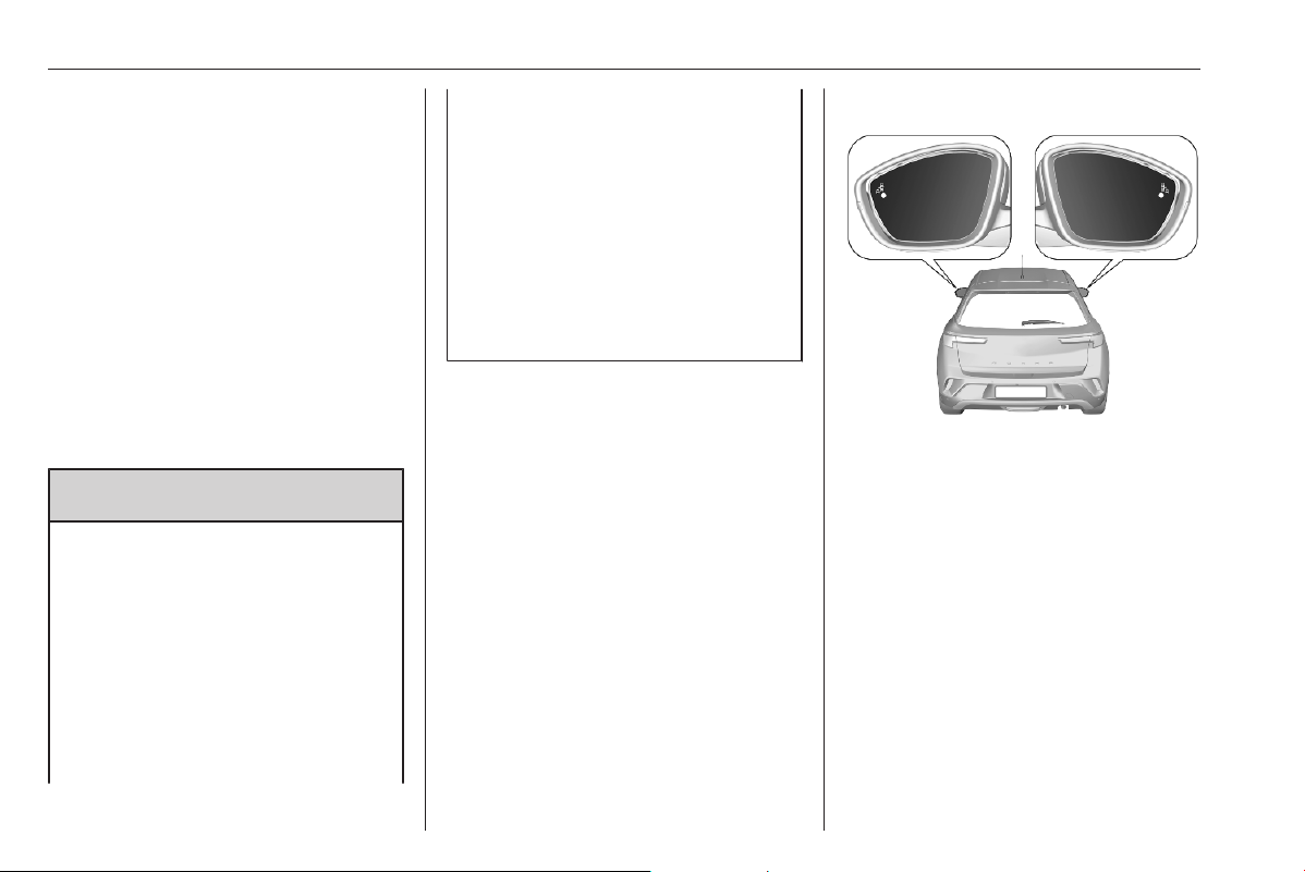
216 Driving and operating
Side blind spot alert
Side blind spot alert assist helps to
avoid crashes due to unintentional
lane departures when an object is
detected within a specified blind spot
zone.
The system displays a visual alert in
each exterior mirror, when detecting
objects that may not be visible in the
interior and exterior mirrors.
Side blind spot alert uses some of the
advanced parking assist sensors
which are located in the front and rear
bumper on both sides of the vehicle.
9 Warning
Side blind spot alert is only a lane
changing aid and does not replace
driver vision.
Side blind spot alert does not
detect:
● Vehicles outside the side blind
zones which may be rapidly
approaching.
● Pedestrians or animals.
● Non-moving objects, e.g.
stationary vehicles, street
lights, road signs, etc.
Failure to use proper care when
changing lanes may result in
damage to the vehicle, injury, or
death. Always check the outside
and rearview mirrors, glance over
your shoulder, and use the turn
signal before changing lanes.
Activation
The system can be activated via the
vehicle settings menu in the Info
Display.
Info Display 3 78.
Functionality
When the system detects a vehicle in
the side blind zone while driving
forwards, an LED will illuminate in the
relevant exterior mirror. If the turn
lights of the relevant side are
activated, the LED will flash.
The LED comes on immediately when
your vehicle is being passed.
The LED comes on after a delay when
your vehicle is passing another
vehicle slowly.

Driving and operating 217
Operation conditions
The following conditions must be
fulfilled for proper operation:
● all vehicles are moving in the
same direction and in adjacent
lanes
● the speed of your vehicle is
between 7 or 20 and 87 mph
● passing a vehicle with a speed
difference of less than 6 mph
● another vehicle is passing with a
speed difference of less than
15 mph
● the traffic flow is normal
● driving on a straight or slightly
curved road
● no plug is connected to the power
outlet of the trailer hitch
● the sensors are not covered by
mud, ice or snow
● the warning zones in the door
mirrors or the detection zones on
front and rear bumper ar not
covered with adhesive labels or
other objects
No alert will be given in the following
situations:
● in the presence of non-moving
objects, e.g. parked vehicles,
barriers, street lamps, road signs
● in very dense traffic, when
moving vehicles might be
confused with a stationary object
● with vehicles moving in the
opposite direction
● driving on a winding road or a
sharp corner
● when passing or being passed by
a very long vehicle, e.g. lorry,
coach, which is at the same time
detected at the rear in the blind
spot angle and present in the
driver's forward field of vision
● when passing too quickly
Deactivation
The system can be activated via the
vehicle settings menu in the Info
Display.
Info Display 3 78.
The state of the system is memorised
when switching off the ignition.
The system is deactivated when a
plug is connected to the power outlet
of the trailer hitch.
Due to adverse weather conditions,
such as heavy rain, false detections
may occur.
Fault
In the event of a fault, C appears in
the Driver Information Centre,
accompanied by a display message.
Seek the assistance of a workshop.
Rear view camera
The rear view camera assists the
driver when reversing. It allows views
of the vehicle's surroundings to be
displayed as a nearly 180° picture in
the Info Display, like a bird's eye view.
9 Warning
The rear view camera does not
replace driver vision. Note that
objects that are outside the
camera's field of view and the
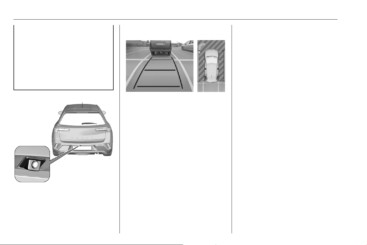
218 Driving and operating
parking assist sensors, e.g. below
the bumper or underneath the
vehicle, are not displayed.
Do not reverse or park the vehicle
using only the rear view camera.
Always check the surrounding of
the vehicle before and during
driving.
The system may use:
● rear view camera, installed
above the rear number plate
● ultrasonic parking sensors in the
rear bumper
The screen in the Info display is
divided into two parts. On the right
there is a view from above the vehicle,
and on the left there is the view from
the rear displayed. If the vehicle is
equipped with ultrasonic parking
sensors, they complete the
information on the view from above
the vehicle.
The area displayed by the rear view
camera is limited. The distance of the
image that appears on the display
differs from the actual distance.
Activation
Rear view camera is activated when
reverse gear is engaged.
Functionality
Different views can be selected in the
left part of the display. Change the
type of view at any time during a
manoeuvre by pressing the touch
field in the left lower zone of the
display and selecting a view from the
view selection menu:
● Standard view
● Auto mode
● Zoom view
● 180° view
The display is immediately updated
with the type of view selected.
Auto mode is activated by default. In
this mode, the system selects the
best view, standard or zoom, to
display according to the information
from the parking sensors.
The state of the system is not kept in
memory when the ignition is switched
off.
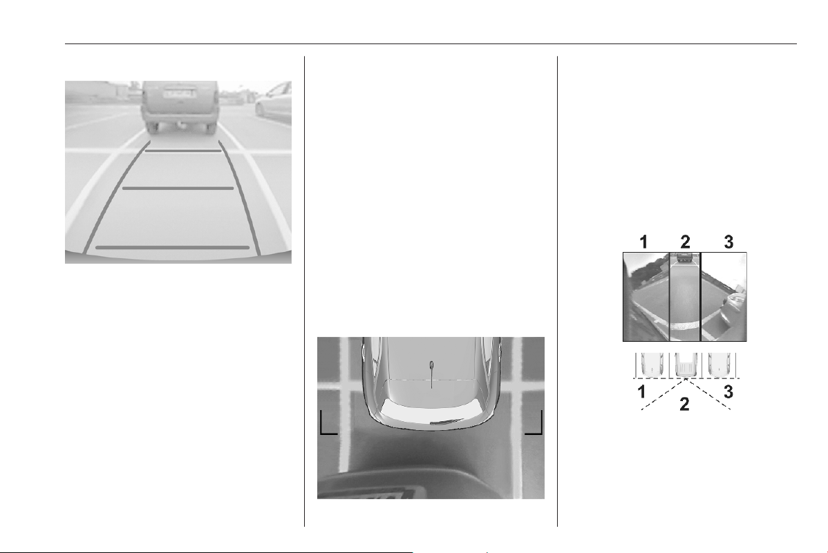
Driving and operating 219
Standard view
The area behind the vehicle is
displayed in the screen. The vertical
lines represent the width of the
vehicle with mirrors unfolded. The
direction of the lines changes with the
position of the steering wheel.
The first horizontal line represents a
distance of about 30 cm beyond the
edge of vehicle's rear bumper. The
upper horizontal lines represent
distances of about 1 m and 2 m.
This view is available in auto mode or
in the view selection menu.
Trajectory lane of the vehicle is
shown in accordance with the
steering angle.
Auto mode
This mode is activated by default. If
the vehicle is equipped with ultrasonic
parking sensors, the automatic view
changes from rear view to a view from
above, as an obstacle is approached
during a manoeuvre.
If the vehicle is not equipped with
ultrasonic parking sensors, the view
needs to be changed manually in the
Info Display.
Zoom view
The rear view camera records the
vehicle's surroundings during the
manoeuvre in order to reconstruct a
view from above the vehicle in its near
surroundings.Thus, the vehicle can
be manoeuvred around obstacles
nearby. This view is available with
auto mode or in the view selection
menu.
180° view
The 180° view facilitates reversing
out of a parking bay, making it
possible to see the approach of
vehicles, pedestrians and cyclists.
This view is not recommended for
carrying out a complete manoeuvre.
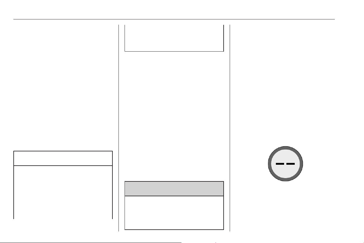
220 Driving and operating
It is made up of three areas: left 1,
centre 2 and right 3. This view is
available from the view selection
menu only.
Deactivation
The rear view camera is deactivated
when:
● a plug is connected to the power
outlet of the trailer hitch
● a certain forward speed is
exceeded or if reverse gear is not
engaged for 7 seconds
● by pressing the icon q in the left
upper corner of the touch screen
System limitations
Caution
For optimal operation of the
system, it is important to keep the
lense of the camera, which is
located in the bumper between the
number plate lights, always clean.
Rinse the lenses with water and
wipe with a soft cloth.
Do not clean the lenses with a
steam-jet or high-pressure jet
cleaner.
The rear view camera may not
operate properly when:
● surrounding is dark
● sun or beam of headlights is
shining directly into camera
lenses
● weather limits visibility, such as
fog, rain, or snow
● camera lenses blocked by snow,
ice, slush, mud, dirt. Clean the
lense, rinse with water, and wipe
with a soft cloth
● vehicle had a rear end accident
● extreme temperature changes
Traffic sign assistant
9 Warning
The actual traffic sign always
takes priority over the traffic sign
displayed in the Driver Information
Centre.
Depending on version, are two
different systems available.
Speed limit system 1
Using the camera at the top of the
windscreen and the vehicle's
integrated navigation system, this
system provides speed limits and end
of speed limits in the Driver
Information Centre.
The system can be activated or
deactivated in the vehicle
personalisation 3 81.
If the system is activated but does not
detect a speed limit sign, the following
sign is displayed:
If the vehicle exceeds the speed limit
by at least 3 mph, the speed limit
displayed flashes about ten seconds.
Speed limiter 3 190.
Cruise control 3 188.
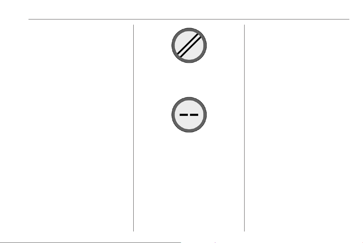
Driving and operating 221
Adaptive cruise control 3 192.
Updating navigation map data
To maintain the performance of the
system, the navigation map should be
updated in periodical intervals. A
navigation map update is available
twice per year.
Further information is avaialble in the
Infotainment system section.
Speed limit system 2
This system displays permanently
speed limit information in the Driver
Information Centre.
Providing the speed limit information
involves the following systems:
● camera at the top of the
windscreen
● vehicle's integrated navigation
system
● telematics service
If travelling on a road with no speed
restrictions, e.g., on German
motorways, the following sign is
displayed:
If no speed limit information can be
provided, the following sign is
displayed:
If a new speed limit is provided, a
confirmation chime is given. The
confirmation chime can be activated /
deactivated in the vehicle
personalisation 3 81.
If the vehicle exceeds the speed limit,
the speed limit displayed after some
time in the Driver Information Centre
flashes and an audible signal is given
after some time. Time of occurrence
varies. Both flashing and audible
signal are terminated after a few
seconds. Due to legal requirements,
the audible signal can only be
deactivated in the vehicle
personalisation until the next time the
ignition is switched on. If the audible
signal is deactivated, 4 illuminates
for a few seconds.
In case of a failure, 4 illuminates
permanently. Consult a workshop.
Speed limiter 3 190.
Cruise control 3 188.
Adaptive cruise control 3 192.
Operation conditions
To provide country-specific speed
limit information, the vehicle needs to
identify the country it is currently in. If
a corresponding country list is
available in the Info Display, the
respective country has to be selected
manually. Otherwise, the country is
automatically selected.
To get valid speed limit information,
the vehicle's current position is sent
via the telematics unit and is
immediately deleted after processing.
Tracking of the vehicle position is not
possible at any time.
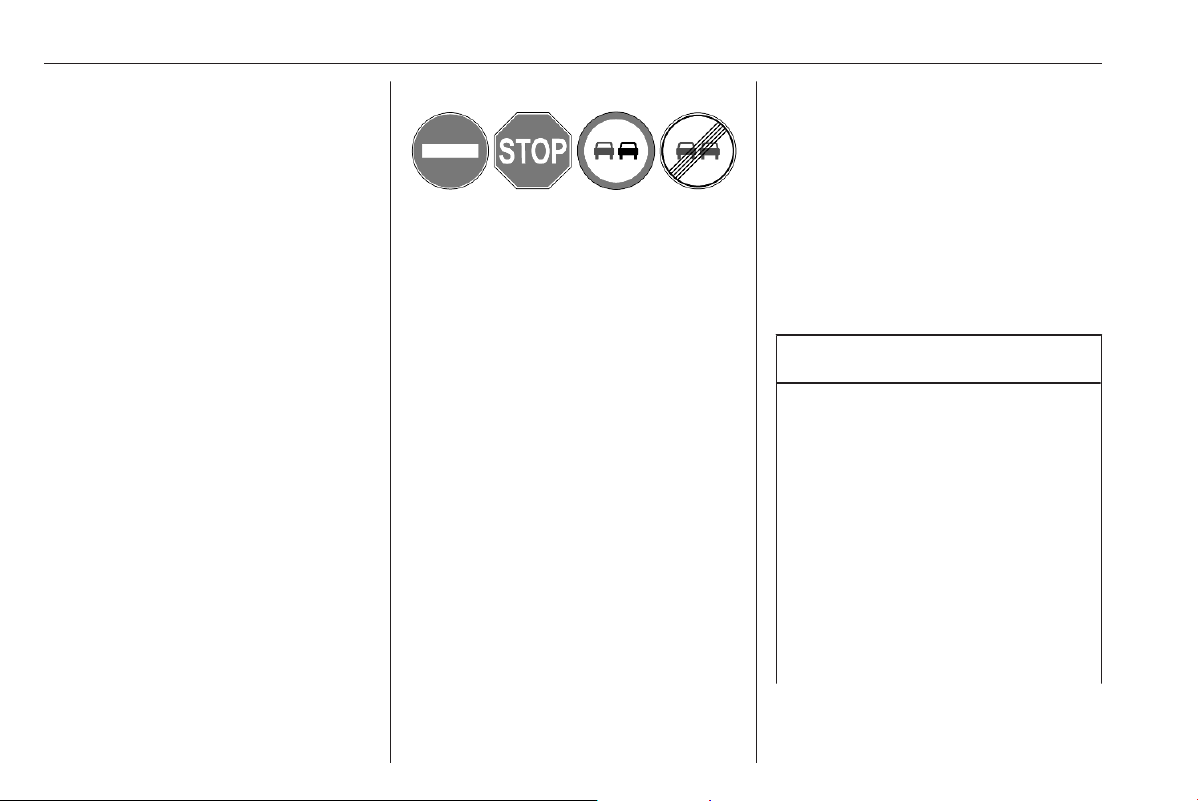
222 Driving and operating
This is not impacted by the privacy
settings of Vauxhall Connect.
Notice
It is possible to report a permanent
speed limit misinformation on our
website.
Updating data
To maintain the performance of the
system, the vehicle software and the
navigation map should be updated in
periodical intervals.
A navigation map update is available
at least once per year. Further
information is available in the
Infotainment system section.
For vehicle software update consult a
workshop.
Other traffic signs
The system detects traffic signs and
displays them in specific page of the
Driver Information Centre.
This system can be activated or
deactivated in the vehicle
personalisation 3 81.
Driver Information Centre 3 77.
System limitations
Traffic sign assistant may not operate
properly when:
● Driving on winding or hilly roads.
● Driving during nighttime.
● Driving with snow chains.
● Driving with a trailer.
● The area of the windscreen,
where the front camera is
located, is not clean or affected
by foreign items, e.g. stickers.
● The visibility is limited because of
the weather, such as fog, rain, or
snow.
● The sun is shining directly into
the camera lens.
● Traffic signs are completely or
partially covered or difficult to
discern.
● Traffic signs are incorrectly
mounted or damaged.
● Traffic signs do not comply with
the Vienna Convention on Road
Signs and Signals.
● The navigation map data is
outdated.
Caution
The system is intended to help the
driver within a defined speed
range to recognise certain traffic
signs. Do not ignore traffic signs
which are not displayed by the
system.
Do not let this special feature
tempt you into taking risks when
driving.
Always adapt speed regarding
road, traffic and weather
conditions.
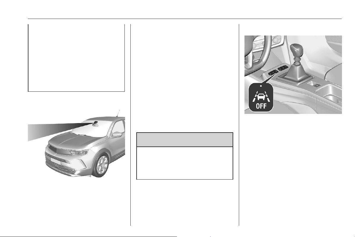
Driving and operating 223
The driver assistance systems do
not relieve the driver from full
responsibility for vehicle
operation.
When driving abroad make sure
the vehicle uses the speed unit of
the respective country. If
necessary, select the correct units
in the Info Display.
Lane departure warning
The lane departure warning system
supports the driver to avoid
unintended leaving of the lane. The
front camera observes road edges,
as well as the lane markings between
which the vehicle is driving. If the
vehicle approaches a road edge or a
lane marking, the system warns the
driver.
Unintended lane departure is not
assumed by the system when the turn
lights are operated and during few
seconds after turn lights have been
switched off.
No warning will be issued with a
dynamic driving, i.e. pressure on the
brake or accelerator pedal.
When the system recognises an
unintended lane departure, the
control indicator L flashes yellow.
9 Warning
This system is a driving aid that
cannot, in any circumstances,
replace the need for vigilance on
the part of the driver.
Activation
If the system is activated, the LED in
the button j is not illuminated. To
activate the system when the system
is deactivated, press j.
The system is only operable at
vehicle speeds above 40 mph.
Deactivation
To deactivate the system, press j
until LED in the button is illuminated.

224 Driving and operating
Fault
In the event of a fault, L and C
appear in the Driver Information
Centre, accompanied by a display
message and a warning chime. Seek
the assistance of a workshop.
System limitations
The system performance may be
affected by:
● covered camera by snow, ice,
slush, mud, dirt, or affected by
windscreen damage or foreign
items, e.g. stickers
● close vehicles ahead
● banked roads
● winding or hilly roads
● poor lighting conditions
● sudden lighting changes
● shining sun directly into the
camera lens
● adverse environmental
conditions, e.g. heavy rain, fog,
or snow
● vehicle modifications, e.g. tyres
● roads with poor lane markings
Lane keep assist
Lane keep assist supports the driver
to avoid unintended leaving of the
lane. The front camera observes road
edges, as well as the lane markings
between which the vehicle is driving.
If the vehicle approaches a road edge
or a lane marking, the steering wheel
is gently turned so that the vehicle
turns back into the lane. The driver
will notice a turning movement of the
steering wheel. Turn steering wheel
in same direction, if the system does
not steer sufficiently. Turn steering
wheel gently into opposite direction, if
lane change is intended.
When the system steers to correct the
trajectory of the vehicle, L flashes
yellow in the Driver Information
Centre. Lane keep assist does not
continuously steer the vehicle.
Unintended lane departure is not
assumed by the system when the turn
lights are operated and during few
seconds after turn lights have been
switched off.
If the system detects that the steering
wheel is not held permanently, it
interrupts a correction after a short
time.
When hands-off driving is detected
during a correction a warning
message appears in the Driver
Information Centre, accompanied by
a warning chime. Every further
hands-off detection prolongs the
warning chime duration.
A lane departure warning in the Driver
Information Centre alerts when the
system cannot hold the vehicle within
the lane and immediate driver´s
action is required.
Notice
The system may be switched off if it
detects lanes which are too narrow,
too wide or too curved.
Following preconditions have to be
fulfilled that the system corrects:
● vehicle speed must be between
40 mph and 112 mph
● the turn lights are not activated
● the electronic stability control is
activated and not in operation
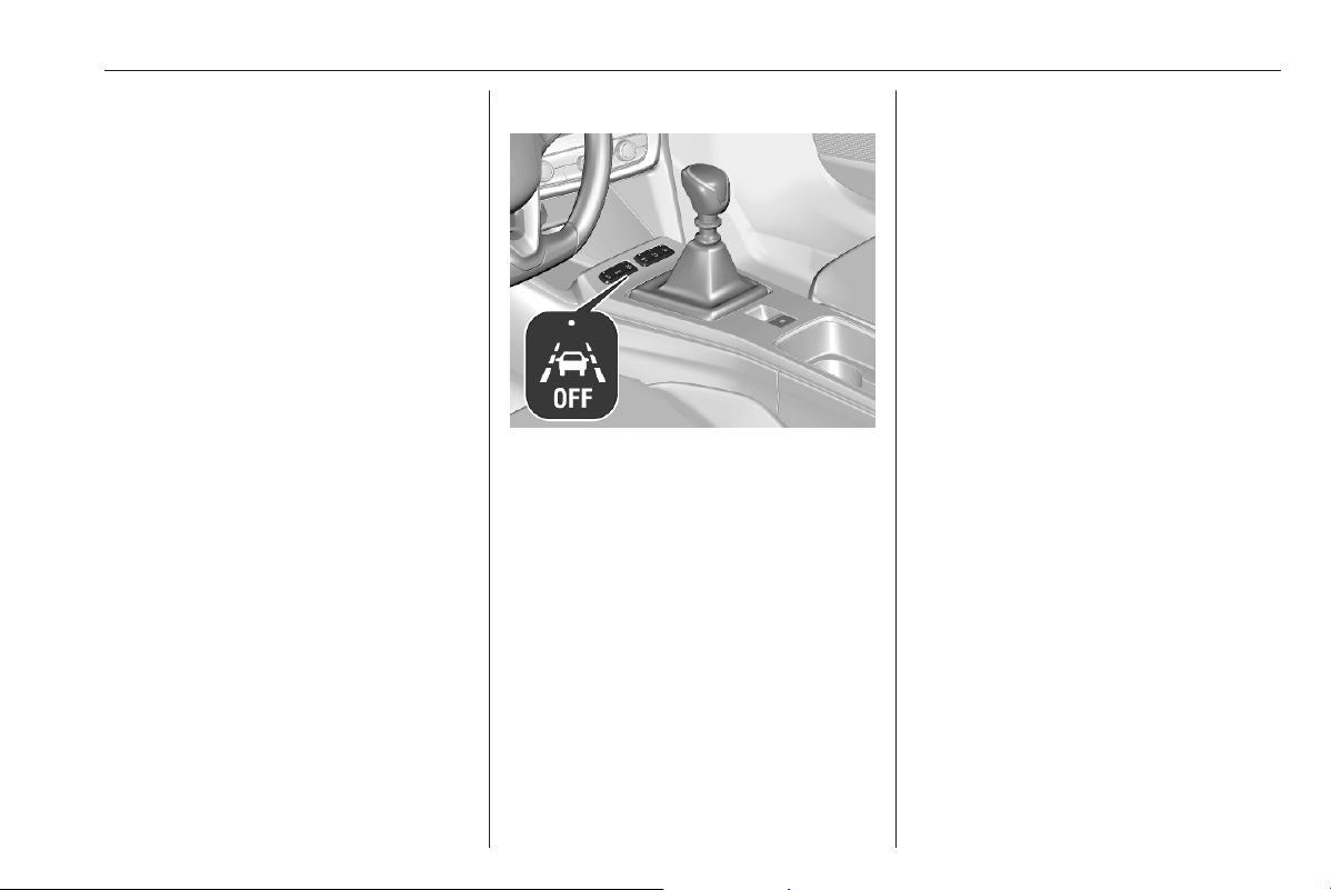
Driving and operating 225
● no plug is connected to the power
outlet of the trailer hitch
● no dynamic driving, i.e. pressure
on the brake or accelerator pedal
● roads with good lane markings
● no temporary spare wheel is
used
● the vehicle is not driven in a tight
corner
● no system fault is present which
prevents corrections
Depending on version, only lane
departure warning system is active,
when a system fault is present, a
spare wheel used, or e.g. a trailer is
attached.
Lane departure warning 3 223.
Activation
Depending on version, the system is
automatically activated when ignition
is switched on. If the system is
activated, the LED in the button j is
not illuminated. To activate the
system when the system is
deactivated, press j.
Deactivation
To deactivate the system, press j
until LED in the button is illuminated.
Fault
In the event of a fault, L and C
appear in the Driver Information
Centre, accompanied by a display
message and a warning chime. Seek
the assistance of a workshop.
System limitations
The system performance may be
affected by:
● covered camera by snow, ice,
slush, mud, dirt, or affected by
windscreen damage or foreign
items, e.g. stickers
● close vehicles ahead
● banked roads
● winding or hilly roads
● poor lighting conditions
● sudden lighting changes
● shining sun directly into the
camera lens
● adverse environmental
conditions, e.g. heavy rain, fog,
or snow
● vehicle modifications, e.g. tyres
● roads with poor lane markings
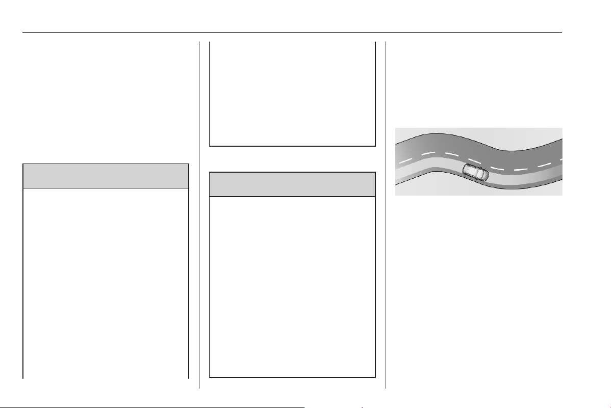
226 Driving and operating
A warning message may appear
when the vehicle is travelling in a long
straight lane on a smooth road
surface even if the driver is holding
the steering wheel properly.
Deactivate the system if the system is
disturbed by tar marks, shadows,
road cracks, temporary or
construction lane markings, or other
road imperfections.
9 Warning
Always keep your attention on the
road and maintain proper vehicle
position within the lane, otherwise
vehicle damage, injury or death
could occur.
The system may not keep the
vehicle in the lane or give an alert,
even if a lane marking is detected.
The steering of the system may
not be sufficient to avoid a lane
departure.
The system may not detect hands-
off driving due to external
influences (road condition and
surface, weather etc). The driver
has full responsibility to control the
vehicle and is always required to
keep the hands on the steering
wheel while driving.
Using the system while towing a
trailer or on slippery roads could
cause loss of control of the vehicle
and a crash. Switch the system off.
Advanced lane keep assist
9 Warning
The system assists the driver in
managing the steering,
acceleration and braking within
the limits of the laws of physics
and the capabilities of the vehicle.
Some road infrastructure
elements or vehicles present on
the road may not be properly seen
or may be poorly interpreted by the
camera and radar, which may lead
to an unexpected change in
direction, a lack of steering
correction and/or inappropriate
management of the acceleration
or braking.
The activated system observes the
lane markings by using the camera
located at the top of the windscreen.
It steers the vehicle inside the
detected lane. The driver will notice a
turning movement of the steering
wheel.
Thus, the current position of the
vehicle within the lane is kept.
When the vehicle is steered by the
system, O illuminates green in the
Driver Information Centre.
However, the control of the vehicle
can be taken over at any time by the
driver. Therefore, the driver needs to
apply some additional force when
turning the steering wheel.
If the system detects that the driver is
not holding the steering wheel firmly
enough, it triggers a series of gradual
alerts. If the interruption takes too
long, the system will be deactivated.
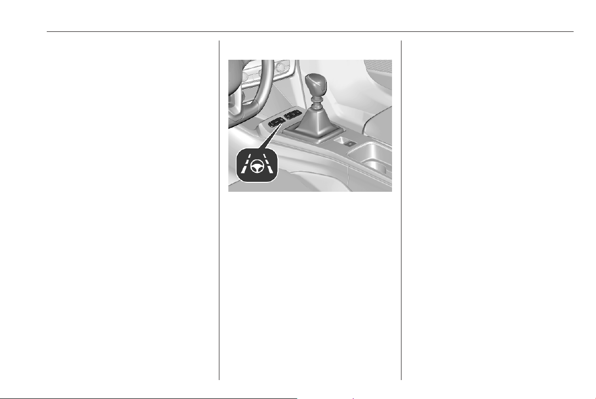
Driving and operating 227
O extinguishes in the Driver
Information Centre. The system has
to be reactivated again by the driver.
Adaptive cruise control 3 192.
Required preconditions
● Adaptive cruise control must be
activated.
● The driver must hold the steering
wheel.
● The turn lights are not activated.
● The Electronic Stability Control is
activated and not in operation.
● No plug is connected to the
power outlet of the trailer hitch.
● No dynamic driving is detected,
i.e. pressure on the brake or
accelerator pedal.
● Roads have good lane markings.
● No temporary spare wheel is
used.
● The vehicle is not driven in a tight
corner.
● No system fault is present which
prevents corrections.
Activation
Press C to activate the system. The
LED in the button is illuminated and
O illuminates green in the Driver
Information Centre.
Deactivation
To deactivate the system, press C.
The LED in the button and O in the
Driver Information Centre are
extinguished.
Pausing / suspending the system
Advanced lane keep assist may be
paused or suspended in the following
situations:
● The Electronic Stability Control is
in operation or it has been
deactivated.
● At least one of the lane markings
is not detected by the system for
several seconds. The system will
be reactivated once the operating
conditions are regained.
● The turn lights are activated.
● Driving outside the lane limits.
● The steering wheel is held too
tight or moved too dynamically.
● The brake pedal or the
accelerator pedal are applied.
● The adaptive cruise control is
paused.
● The road is too narrow or wide.
● The lateral acceleration in curves
is too high.
O illuminates grey in the Driver
Information Centre.

228 Driving and operating
Fault
In the event of a fault, O and C
appear yellow in the Driver
Information Centre, accompanied by
a display message and a warning
chime. Seek the assistance of a
workshop.
System limitations
The system performance may be
affected by:
● covered camera by snow, ice,
slush, mud, dirt, or affected by
windscreen damage or foreign
items, e.g. stickers
● close vehicles ahead
● banked roads
● winding or hilly roads
● poor lighting conditions
● sudden lighting changes
● shining sun directly into the
camera lens
● adverse environmental
conditions, e.g. heavy rain, fog,
or snow
● vehicle modifications, e.g. tyres
● roads with poor lane markings
A warning message may appear
when the vehicle is travelling in a long
straight lane on a smooth road
surface even if the driver is holding
the steering wheel properly.
Deactivate the system if the system is
disturbed by tar marks, shadows,
road cracks, temporary or
construction lane markings, or other
road imperfections.
9 Warning
Always keep your attention on the
road and maintain proper vehicle
position within the lane, otherwise
vehicle damage, injury or death
could occur.
The system may not keep the
vehicle in the lane or give an alert,
even if a lane marking is detected.
The steering of the system may
not be sufficient to avoid a lane
departure.
The system may not detect hands-
off driving due to external
influences (road condition and
surface, weather etc). The driver
has full responsibility to control the
vehicle and is always required to
keep the hands on the steering
wheel while driving.
Using the system while towing a
trailer or on slippery roads could
cause loss of control of the vehicle
and a crash. Switch the system off.
Driver alert
The driver alert system monitores the
driving time and the vigilance of the
driver. Monitoring the vigilance of the
driver is based on the trajectory
variations of the vehicle compared to
the lane markings.
The system cannot replace the need
for vigilance on the part of the driver.
Taking a break is recommended as
soon as feeling tired or at least every
two hours. Do not drive when feeling
tired.

Driving and operating 229
Activation or Deactivation
The system can be activated or
deactivated in the vehicle
personalisation 3 81.
When the system is deactivated 2
may illuminate in the Driver
Information Centre.
The system is automatically activated
when ignition is switched on.
Driving time alert
The driver gets notified by a pop-up
reminder symbol € in the Driver
Information Centre simultaneously
with an acoustic alert if the driver has
not taken a break after two hours of
driving at a speed above 40 mph. The
alert is repeated hourly until the
vehicle is stopped, no matter how
vehicle speed evolves.
The counting of driving time alert is
reset when the ignition has been
switched off for a few minutes or the
driver's seat belt has been
unfastened and the driver's door has
been opened.
Driver drowsiness detection
The system monitors the driver's level
of vigilance at speeds above 40 mph.
A camera at the top of the windscreen
detects variations in trajectory
compared to the lane markings.
The system may perform a learning
procedure for up to 30 minutes after
the start of the monitoring. During this
period, the driver's individual driving
behaviour is analysed and no alert is
given.
If the trajectory of the vehicle
suggests a certain level of
drowsiness or inattention by the
driver, the system triggers the first
level of alert. The driver is notified by
a message and an audible signal is
given.
After three first level alerts, the
system triggers a new alert with a
message, accompanied by a more
pronounced audible signal.
In certain driving conditions such as
poor road surface or strong winds
etc., the system may give alerts
independent of the driver's level of
vigilance.
The driver drowsiness detection is
reinitialised in the following situations:
● the ignition has been switched off
for a few minutes
● the speed remains below
40 mph for a few minutes
● the driver's seat belt has been
unfastened and the driver's door
has been opened
System limitations
In the following situations, the system
may not operate properly or even not
operate at all:
● poor visibility caused by
inadequate lighting of the
roadway, falling snow, heavy
rain, dense fog etc.
● dazzle caused by headlamps of
oncoming vehicles, low sun,
reflections on damp roads,
leaving a tunnel, alternating
shade and light etc.
● no lane markings detected or
multiple lane markings due to
roadworks
● close vehicles ahead
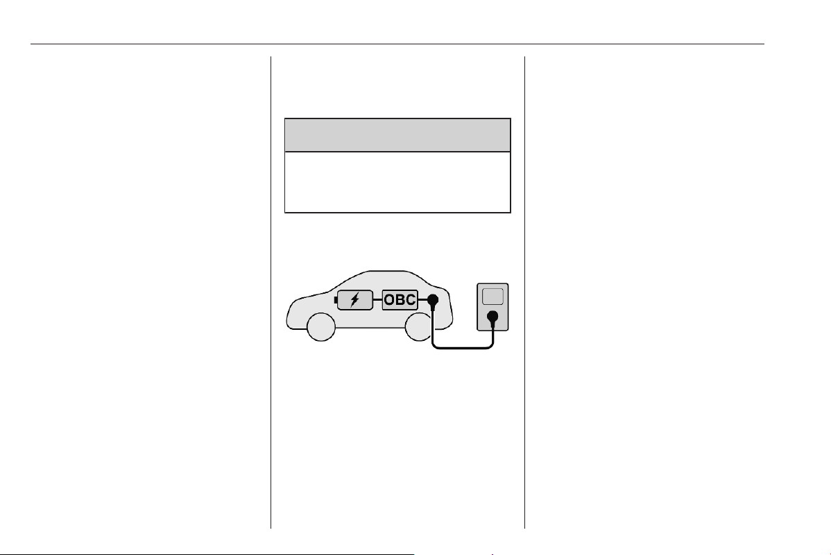
230 Driving and operating
● winding roads or narrow roads
● advanced lane keep assist is
active
● covered camera by snow, ice,
slush, mud, dirt, or affected by
windscreen damage or foreign
items, e.g. stickers, 2 may
appear in the Driver Information
Centre, accompanied by a
message
● in the event of a system fault,
2 may appear in the Driver
Information Centre,
accompanied by a message and
a warning chime
Charging
General information
9 Warning
Persons with a pacemaker should
consult a doctor for possible
precautions.
Charging the vehicle's high voltage
battery depends upon several factors:
● high voltage battery of the vehicle
● internal onboard charger (OBC)
● charging cable
● external charging device
The charging cable connects the
vehicle with an external charging
device providing electric power. This
may be a domestic electrical outlet, a
Green'Up socket, a wall box or a
public charging station.
The high voltage battery is charged
with direct current (DC) only. When
charging the vehicle with alternating
current (AC), AC has to be converted
into DC. This is done by the vehicle's
onboard charger. The onboard
charger is available with 7.4 kW
(single-phase) and 11 kW (3-phase).
If the vehicle is charged at a public DC
charging station, no DC conversion is
required. The high voltage battery
can be directly charged with DC
provided by the DC charging station.
The speed of charging the vehicle's
high voltage battery depends upon
the weakest element of the charging
chain. To achieve the maximum
charging speed, charging cable and
charging device have to be attuned to
each other.
Notice
Make sure that the charging cable
used fits to the vehicle's onboard
charger.
Charging types 3 231.
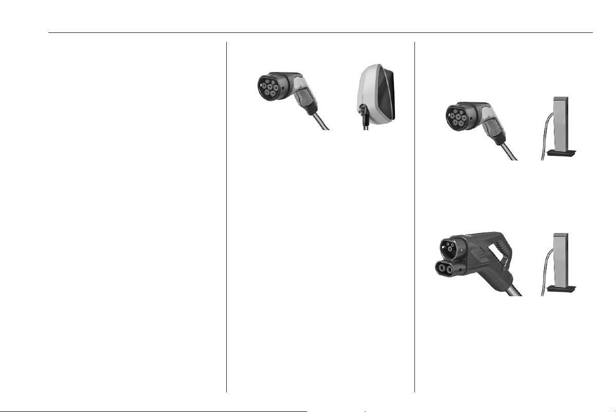
Driving and operating 231
Charging cable 3 238.
Electric power consumption and
range
The electric power consumption
(combined) is within a range of 15.17
to 12.77 kWh/100 km.
The range is up to 250 miles.
For the values specific to your
vehicle, refer to the EEC Certificate of
Conformity provided with your vehicle
or other national registration
documents.
The determination of electric power
consumption is regulated by directive
R (EC) No. 715/2007 and No.
2017/1151 (in the latest applicable
version).
Charging types
There are different types of charging
the vehicle's high voltage battery.
Charging at wallboxes
A wallbox is a charging unit for private
households. It provides a charging
cable which has to be connected to
the vehicle's charging port. Some
wallboxes do not provide a charging
cable. In this case, a separate
charging cable is required which has
to be connected to both the wallbox
and the charging port of the vehicle.
Charging time may take approx. 5
hours with a charging power of 11 kW
or 7.5 hours with a charging power of
7.4 kW.
Charging at charging stations
Charging stations may provide
alternating current (AC) or direct
current (DC). Charging time may vary
depending on the charging station,
DC charging stations provide the
fastest charging. To charge the
vehicle's battery, the charging cable
of the charging station has to be
connected to the charging port of the
vehicle.
● AC charging station: Charging
time may take approx. 5 hours
with a charging power of 11 kW
or 7.5 hours with a charging
power of 7.4 kW.
● DC charging station: Up to
approx. 80% of battery capacity
may be charged in approx. 30
minutes at a charging power of
100 kW.
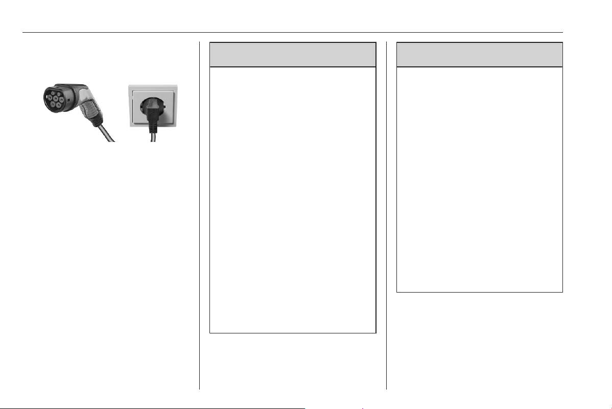
232 Driving and operating
Charging at domestic electrical
outlets
The vehicle's high voltage battery can
be charged at a domestic electrical
outlet. Connect the charging cable to
the vehicle's charging port and to the
domestic electrical outlet.
Charging time may take approx. 30
hours with a charging power of 1.8
kW.
Charging cable
Depending on the charging type,
different charging cables are used.
9 Warning
Improper use of portable charging
cables may cause a fire, electrical
shock, or burns, and may result in
damage to property, serious
injury, or death.
● Do not use extension cables,
multi-outlet power strips,
splitters, grounding adaptors,
surge protectors, or similar
devices.
● Do not use an electrical socket
that is worn or damaged, or one
that will not hold the plug firmly
in place.
● Do not immerse the charging
cable into any liquid.
● Do not use an electrical socket
that is not properly grounded.
● Do not use an electrical socket
that is on a circuit with other
electrical loads.
9 Warning
Read all the safety warnings and
instructions before using this
product. Failure to follow the
warnings and the instructions may
result in electric shock, fire, and /
or serious injury.
Never leave children unattended
near the vehicle while the vehicle
is charging and never allow
children to play with the charging
cable.
If the plug provided does not fit the
electrical outlet, do not modify the
plug. Arrange for a qualified
electrician to inspect the electrical
outlet.
Do not put fingers into the electric
vehicle connector.
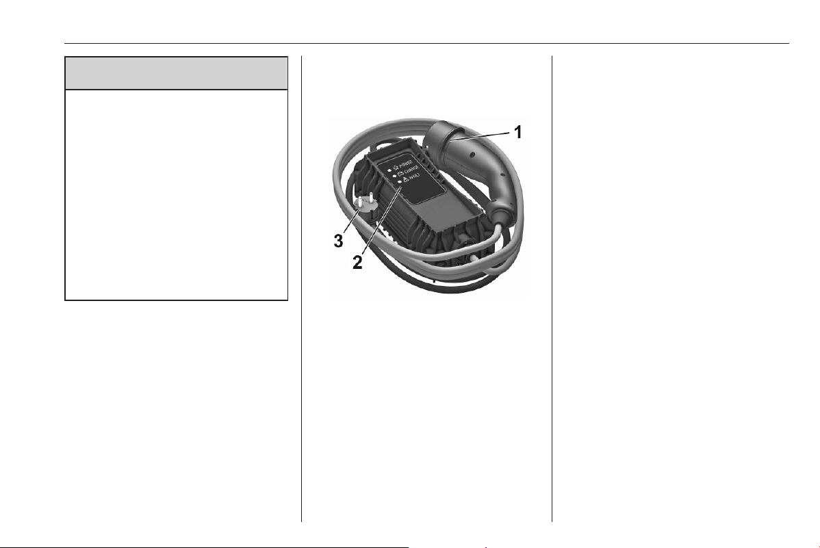
Driving and operating 233
9 Danger
There is a risk of electric shock
that may cause personal injury or
death.
Do not use the charging cable if
any part of the charging cable is
damaged.
Do not open or remove the
charging cable cover.
Service by qualified personnel
only. Connect the charging cable
to a properly grounded outlet with
cables that are not damaged.
Basic domestic cable (mode 2) /
enhanced domestic cable (mode
2)
1. Vehicle plug
2. Status indicators
3. Wall plug
Basic domestic cables (mode 2) are
used for charging at domestic
electrical outlets. A basic domestic
cable (mode 2) consists of a vehicle
plug, a control box and a plug for the
domestic electrical outlet. The control
box has an intergrated charge
controller and several LEDs
indicating the charging status.
Enhanced domestic cables (mode 2)
are similar to basic domestic cables
(mode 2). However, the charging
performance of enhanced domestic
cables (mode 2 charging) is better
than the charging performance of
basic domestic cables (mode 2).
Enhanced domestic cables (mode 2)
are used at Green'Up sockets which
have to be installed by a certified
electrician at the customer's site.
Charging cable status indicators
After plugging in the charging cable,
it will perform a quick self test and all
status indicators illuminate for a
moment. For the functions of the
status indicators, refer to the manual
of the charging cable manufacturer.
Important information about
portable electric vehicle charging
● Charging an electric vehicle can
stress a building's electrical
system more than a typical
household appliance.
● Before you plug in to any
electrical outlet, have a qualified
electrician inspect and verify the
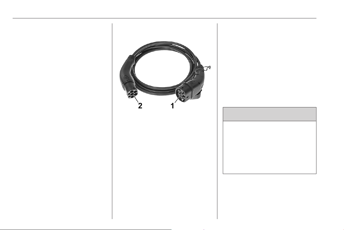
234 Driving and operating
electrical system (electrical
outlet, wiring, junctions and
protection devices) for heavy-
duty service at a 10 A continuous
load.
● Electrical outlets may wear out
with normal usage or be
damaged over time, making them
unsuitable for electric vehicle
charging.
● Check the electrical outlet / plug
while charging and discontinue
use if the electrical outlet / plug is
hot, then have the electrical
outlet serviced by a qualified
electrician.
● When outdoors, plug into an
electrical outlet that is weather-
proof while in use.
● Mount the charging cable to
reduce strain on the electrical
outlet / plug.
Mode 3 charging cable
1. Vehicle plug
2. Plug for wall box / AC charging
station
Mode 3 charging cables are used for
charging at wall boxes and AC
charging stations. A mode 3 charging
cable provides a vehicle plug and a
plug for the wall box / AC charging
station. Wall boxes / AC charging
stations may provide an integrated
mode 3 charging cable. For more
information on the mode 3 charging
cable, refer to the manual of the
charging cable manufacturer.
Mode 4 charging cable
Notice
Only use DC charging cables shorter
than 30 metres.
Mode 4 charging cables are used for
DC charging. Since mode 4 charging
cables are integrated within DC
charging stations, they only provide a
vehicle plug.
Charging
9 Warning
Persons with a pacemaker or
similar devices should consult a
doctor for possible precautions.
If in doubt, during charging do not
remain inside or near the vehicle,
near the charging cable or the
charging unit.
In order to ensure the compatibility of
plug and outlet, different labels are
used. The labels are located on the
inside of the vehicle's charging port
flap. Make sure to connect only a
cable of the same type.
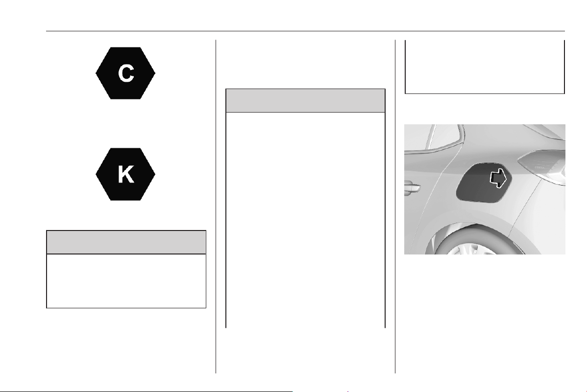
Driving and operating 235
Type 2 plug or outlet used for AC
charging
FF plug or outlet used for DC charging
9 Warning
Avoid any entry of fluids into the
charging port of the vehicle, the
vehicle plug of the charging cable
and the domestic electrical outlet.
When charging at a public AC
charging station / public DC charging
station, follow the instructions for the
use of the respective charging
station. Public AC charging stations
may not provide an integrated
charging cable. In this case, a
portable mode 3 charging cable is
required.
9 Warning
When charging at a domestic
electrical outlet, only use an outlet
which is properly grounded and
protected by a 30 mA differential
switch.
Only use a domestic electrical
outlet protected by a circuit
breaker adapted to the amperage
of the electrical circuit.
Have a qualified electrician check
the electrical installation to be
used. The installation has to be in
compliance with national
standards and compatible with the
vehicle.
When using a dedicated domestic
electrical outlet, have it installed
by a qualified electrician.
Make sure that the electrical
outlet, the plug and the cable do
not support the weight of the
control box.
1. Shift into P and switch off the
vehicle.
2. Push the charging port flap to
release it.
3. If necessary, take the charging
cable out of the load
compartment.
4. If necessary, plug in the plug of
the charging cable into the
corresponding port of the external
power source.
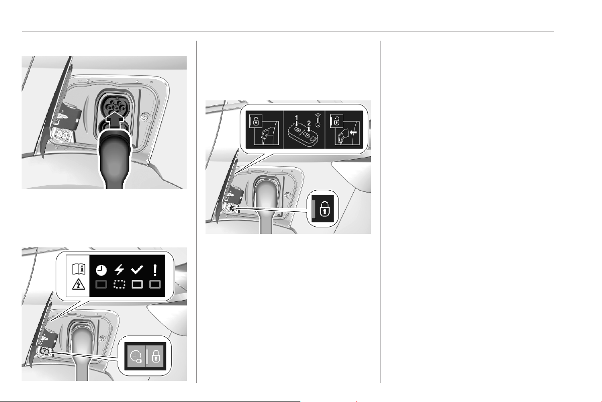
236 Driving and operating
Charging cable 3 238.
5. Plug in the vehicle plug of the
mode 3 charging cable into the
charging port of the vehicle.
Charging status 3 238.
The start of charging is indicated
by the green flashing of the status
indicator at the charging port and
at the control box of the charging
cable, if available.
Once charging, the vehicle plug will
be locked to the charging port and
cannot be disconnected while
charging is active. - indicator
illuminates.
Charging types 3 231.
Cancelling the charging process
Notice
At public charging stations, the
cancelling and subsequent
resuming of the charging process
may cause additional costs.
Once the charging process has
started, only the driver's door can be
unlocked without cancelling the
charging process. Therefore,
activate the driver's door only
function in the vehicle
personalisation.
Press < on the remote control to
cancel the charging process at any
time.
Press < twice to cancel the charging
process at any time if the function
driver's door only is activated in the
vehicle personalisation.
Central locking system 3 10.
Vehicle personalisation 3 81.
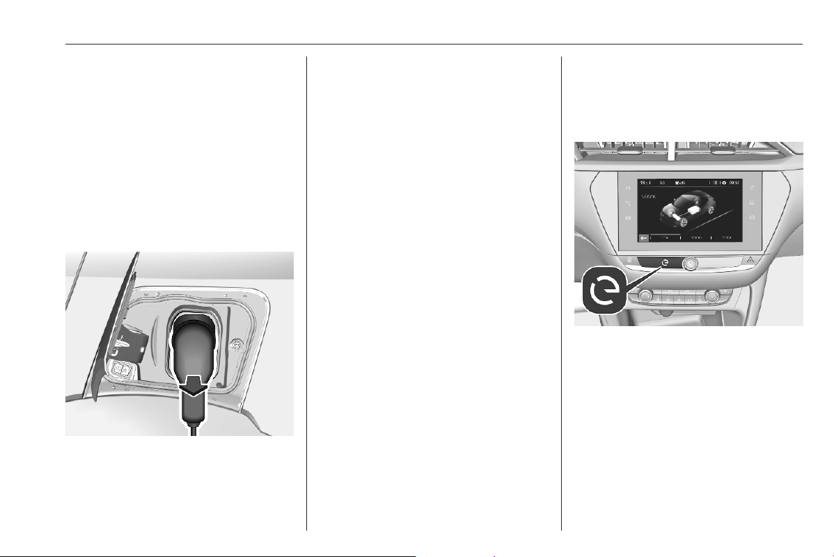
Driving and operating 237
Stop charging
The high voltage battery is fully
charged if the status indicator on the
charging port permanently illuminates
green.
1. Unlock the vehicle before
removing the vehicle plug from
the charging port.
If the vehicle is already unlocked,
lock the vehicle and unlock it
again.
2. Disconnect the vehicle plug of the
charging cable from the charging
port within 30 seconds after
unlocking.
3. Close the charging port flap by
pressing firmly in the centre to
latch properly.
4. Disconnect the charging cable
from the external power source.
5. If necessary, store the charging
cable in the load compartment.
While the charging cable is plugged
into the vehicle, the vehicle cannot be
driven.
Programmable charging
By default, charging starts as soon as
the charging cable is connected to the
charging port of the vehicle. It is also
possible to schedule charging using
the Info Display.
Programmable charging is only
possible when charging at a domestic
electrical outlet / Green'Up socket or
a wall box.
Programmable charging is also
available via the MyVauxhall App.
Notice
On vehicles without integrated
navigation system, programmable
charging can only be used via the
MyVauxhall App.
1. Press m.
2. Select Charge.
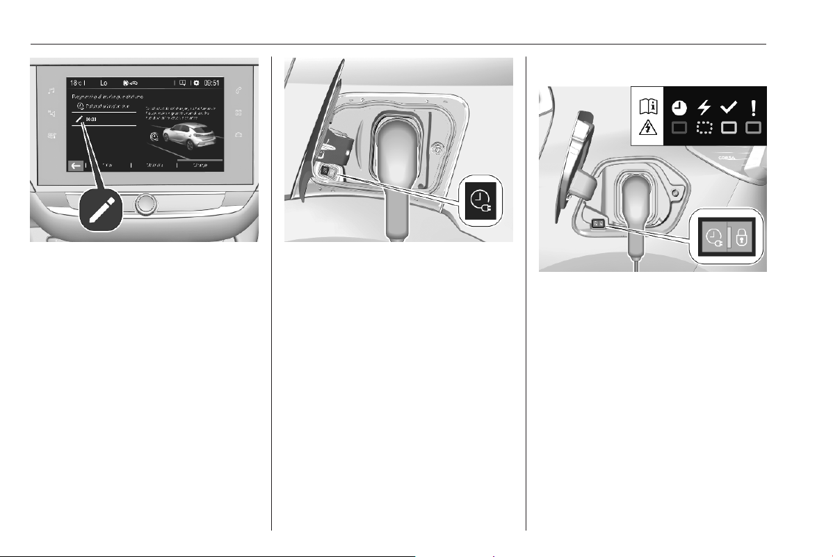
238 Driving and operating
3. Press /.
4. Define the number of hours and
minutes after which the loading
process starts.
5. Press OK.
6. Plug in the vehicle.
7. Within 1 minute, press b to
activate programmable charging.
8. Depending on version, lock the
vehicle.
The status indicator illuminates blue
indicating that programmable
charging is active.
Charging 3 234.
Charging status 3 238.
Charging status
If the vehicle is plugged in and the
ignition is switched off, the charging
status indicator indicates the
following:
● Illuminates white: welcome
lighting when charging port flap is
opened
● Flashes white: charging in
preperation
● Illuminates green: charging
complete
● Flashes green: charging in
process
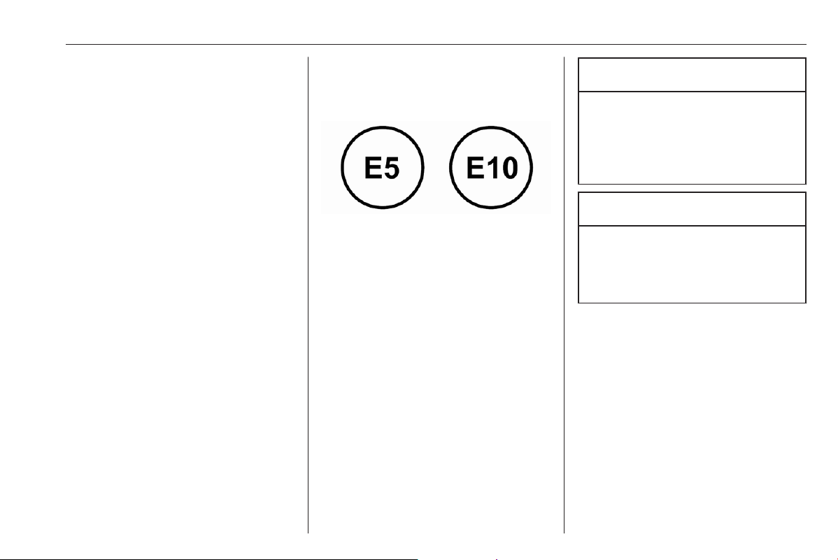
Driving and operating 239
● Illuminates red: charging fault
● Illuminates blue: programmable
charging active
A charging fault has occured if the
vehicle is plugged in and the charging
status indicator is off.
Further charging status indicators are
located on the control box of the basic
domestic cable (mode 2) / enhanced
domestic cable (mode 2).
Charging cable 3 232.
Programmable charging 3 237.
Fuel
Fuel for petrol engines
Only use unleaded fuel that complies
with European standard EN 228 or
E DIN 51626-1 or equivalent.
The engine is capable of running with
fuel that contains up to 10% ethanol
(e.g. named E10).
Use fuel with the recommended
octane rating. A lower octane rating
can reduce engine power and torque
and slightly increases fuel
consumption.
Caution
Do not use fuel or fuel additives
that contain metallic compounds
such as manganese-based
additives. This may cause engine
damage.
Caution
Use of fuel with a lower octane
rating than the lowest possible
rating could lead to uncontrolled
combustion and engine damage.
The engine specific requirements
regarding octane rating are given in
the engine data overview 3 288. A
country-specific label at the fuel filler
flap can supersede the requirement.
In certain countries, the use of a
particular fuel, e.g. a specific octane
rating, may be required to ensure
proper engine operation.
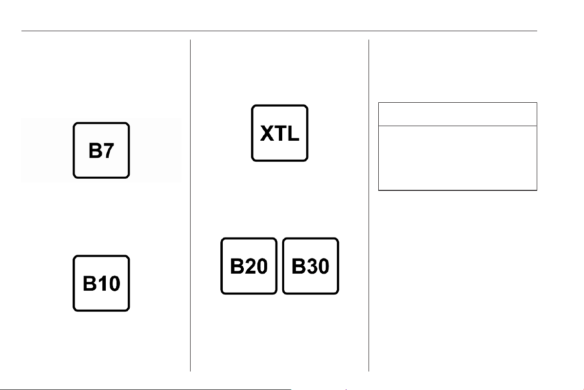
240 Driving and operating
Fuel for diesel engines
The Diesel engines are compatible
with bio-fuels that conform to current
and future European standards and
and can be obtained from filling
stations:
Diesel fuel that meets standard
EN590 mixed with a biofuel that
meets standard EN14214 (possibly
containing up to 7% Fatty Acid Methyl
Ester).
Diesel fuel that meets standard
EN16734 mixed with a biofuel that
meets standard EN14214 (possibly
containing up to 10% Fatty Acid
Methyl Ester).
Paraffinic Diesel fuel that meets
standard EN15940 mixed with a
biofuel that meets standard
EN14214 (possibly containing up to
7% Fatty Acid Methyl Ester).
The use of B20 or B30 fuel meeting
standard EN16709 is possible in your
Diesel engines. However, this use,
even occasional, requires strict
application of the special servicing
conditions referred to as "Arduous
conditions".
For more information, seek the
assistance of a workshop.
Caution
The use of any other type of (bio)
fuel (vegetable or animal oils, pure
or diluted, domestic fuel etc.) is
strictly prohibited (risk of damage
to the engine and fuel system).
Notice
The only Diesel additives authorised
for use are those that meet the
B715000 standard.
Low temperature operation
At temperatures below 0 °C, some
diesel products with biodiesel blends
may clog, freeze or gel, which may
affect the fuel supply system. Starting
and engine operation may not work
properly. Make sure to fill winter
grade diesel fuel at ambient
temperatures below 0 °C.
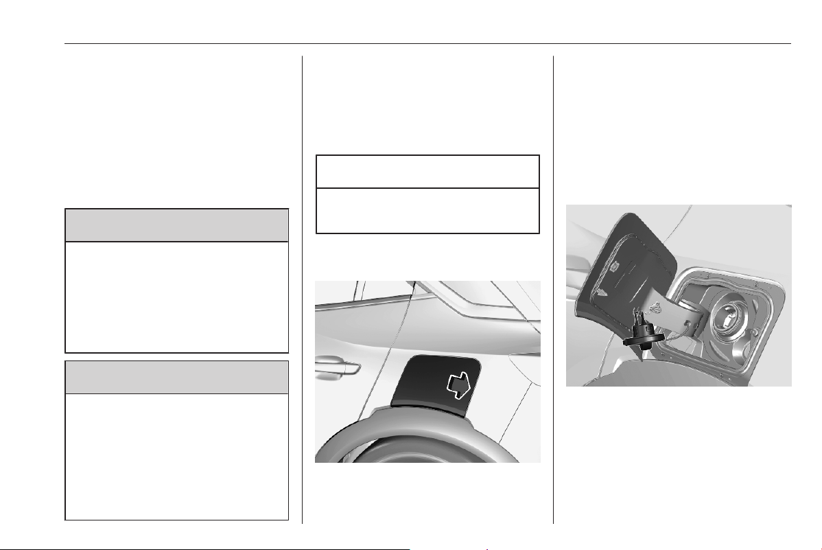
Driving and operating 241
Arctic grade diesel fuel can be used
at extremely low temperatures below
-20 °C. Using this fuel grade in warm
or hot climates is not recommended
and may cause engine stalling, poor
starting or damage on the fuel
injection system.
Refuelling
9 Danger
Before refuelling, switch off
ignition and any external heaters
with combustion chambers.
Follow the operating and safety
instructions of the filling station
when refuelling.
9 Danger
Fuel is flammable and explosive.
No smoking. No naked flames or
sparks.
If you can smell fuel in your
vehicle, have the cause of this
remedied immediately by a
workshop.
A label with symbols at the fuel filler
flap is indicating the allowed fuel
types. In Europe the pump nozzles of
the filling stations are marked with
these symbols. Refuel only the
allowed fuel type.
Caution
In case of misfuelling, do not
switch on ignition.
Fuel filler flap is located at left rear
side of vehicle.
The fuel filler flap can only be opened
if the vehicle is unlocked. Release the
fuel filler flap by pushing the flap.
Petrol and diesel refuelling
Notice
Diesel-engined vehicles may be
equipped with a mis-fuel inhibitor
that prevents the refuelling with
petrol.
To open, turn the cap slowly
anticlockwise.
The fuel filler cap can be attached to
the hook on the fuel filler flap.
Place the nozzle in straight position to
the filler neck and press with slight
force to insert.
To refuel, switch on pump nozzle.

242 Driving and operating
After the automatic cut-off, the tank
can be topped up by operating the
pump nozzle a maximum of two more
times.
Caution
Wipe off any overflowing fuel
immediately.
To close, turn the fuel filler cap
clockwise until it clicks.
Close the flap and allow it to engage.
Fuel filler cap
Only use genuine fuel filler caps.
Diesel-engined vehicles have special
fuel filler caps.
Fuel consumption - CO
2
-
Emissions
The fuel consumption (combined) is
within a range of 47.1 to 51.4 mpg.
The CO
2
emission is within a range of
148 to 113 g/km.
General information
For the values specific to your
vehicle, refer to the EEC Certificate of
Conformity provided with your vehicle
or other national registration
documents.
The determination of fuel
consumption is regulated by directive
R (EC) No. 715/2007 and No.
2017/1151 (in the latest applicable
version).
The specification of CO
2
emission is
also a constituent of the directive.
The figures given must not be taken
as a guarantee for the actual fuel
consumption of a particular vehicle.
Furthermore, fuel consumption is
dependent on personal driving style
as well as road and traffic conditions.
All values are based on the EU base
model with standard equipment.
The calculation of fuel consumption
takes into account the vehicle's kerb
weight, ascertained in accordance
with the regulations. Optional
equipment may result in slightly
higher fuel consumption and
CO
2
emission levels and a lower
maximum speed.

Driving and operating 243
Trailer hitch
General information
Caution
For new vehicles, only tow a trailer
after having driven at least 620
miles.
Only use towing equipment that has
been approved for your vehicle.
Entrust retrofitting of towing
equipment to a workshop. It may be
necessary to make changes that
affect the cooling system, heat
shields or other equipment.
Trailers equipped with LED lights are
not suitable for the wiring harness of
this trailer hitch.
Fitting of towing equipment could
cover the opening of the towing eye.
If this is the case, use the coupling ball
bar for towing. Always keep the
coupling ball bar in the vehicle to have
it on hand if needed.
Driving characteristics and
towing tips
Before attaching a trailer, lubricate
the coupling ball. However, do not do
so if a stabiliser, which acts on the
coupling ball, is being used to reduce
snaking movements.
During trailer towing do not exceed a
speed of 50 mph. A maximum speed
of 60 mph is only appropriate if an
oscillation damper is used and the
permissible gross trailer weight does
not exceed the vehicle's curb weight.
For trailers with low driving stability
and caravan trailers, the use of an
oscillation damper is strongly
recommended.
If the trailer starts snaking, drive more
slowly, do not attempt to correct the
steering and brake sharply if
necessary.
When driving downhill, drive in the
same gear as if driving uphill and
drive at a similar speed.
Adjust tyre pressure to the value
specified for full load 3 291.
Trailer towing
Trailer loads
The permissible trailer loads are
vehicle and engine-dependent
maximum values which must not be
exceeded. The actual trailer load is
the difference between the actual
gross weight of the trailer and the
actual coupling socket load with the
trailer coupled.
The permissible trailer loads are
specified in the vehicle documents. In
general, they are valid for gradients
up to 12%.
The permissible trailer load applies
up to the specified incline and at sea
level. Since engine power decreases
as altitude increases due to the air
becoming thinner, therefore reducing
climbing ability, the permissible gross
train weight also decreases by 10%
for every 1000 m of altitude. The
gross train weight does not have to be
reduced when driving on roads with
slight inclines (less than 8%, e.g.
motorways).

244 Driving and operating
The permissible gross train weight
must not be exceeded. This weight is
specified on the identification plate
3 285.
Vertical coupling load
The vertical coupling load is the load
exerted by the trailer on the coupling
ball. It can be varied by changing the
weight distribution when loading the
trailer.
The maximum permissible vertical
coupling load (61 kg) is specified on
the towing equipment identification
plate and in the vehicle documents.
Always aim for the maximum vertical
coupling load, especially in the case
of heavy trailers. The vertical coupling
load should never fall below 25 kg.
Rear axle load
When the trailer is coupled and the
towing vehicle fully loaded, the
permissible rear axle load (see
identification plate or vehicle
documents) may be exceeded by
60 kg, the gross vehicle weight rating
must not be exceeded. If the
permissible rear axle load is
exceeded, a maximum speed of
60 mph applies.

Vehicle care 245
Vehicle care
General Information ................... 245
Accessories and vehicle
modifications .......................... 245
Vehicle storage ........................ 248
End-of-life vehicle recovery ..... 249
Vehicle checks ........................... 250
Performing work ...................... 250
Bonnet ..................................... 251
Engine oil ................................. 251
Engine coolant ......................... 253
Washer fluid ............................ 254
Brakes ..................................... 254
Brake fluid ............................... 254
Vehicle battery ......................... 254
High voltage battery ................ 257
Diesel fuel system bleeding ..... 257
Wiper blade replacement ........ 258
Bulb replacement ....................... 258
LED headlights ........................ 258
Front fog lights ......................... 258
Tail lights ................................. 259
Number plate light ................... 259
Interior lights ............................ 259
Electrical system ........................ 260
Fuses ....................................... 260
Vehicle tools .............................. 260
Tools ........................................ 260
Wheels and tyres ....................... 261
Winter tyres ............................. 261
Tyre designations .................... 261
Tyre pressure .......................... 262
Tyre deflation detection
system .................................... 263
Tread depth ............................. 263
Changing tyre and wheel size . 264
Wheel covers ........................... 264
Tyre chains .............................. 265
Tyre repair kit .......................... 265
Wheel changing ....................... 268
Spare wheel ............................ 269
Jump starting ............................. 273
Towing ....................................... 274
Towing the vehicle ................... 274
Towing another vehicle ........... 276
Appearance care ....................... 276
Exterior care ............................ 276
Interior care ............................. 278
Floor mats ............................... 278
General Information
Accessories and vehicle
modifications
We recommend the use of genuine
parts and accessories and factory
approved parts specific for your
vehicle type. We cannot assess or
guarantee reliability of other products
- even if they have a regulatory or
otherwise granted approval.
Any modification, conversion or other
changes made to standard vehicle
specifications (including, without
limitation, software modifications,
modifications of the electronic control
units) may invalidate the warranty
offered by Vauxhall. Furthermore,
such changes may affect driver
assistance systems, may impact fuel
or electric power consumption, CO
2
emissions and other emissions of the
vehicle and cause the vehicle to no
longer conform to the operating
permit, impacting the validity of your
vehicle registration.
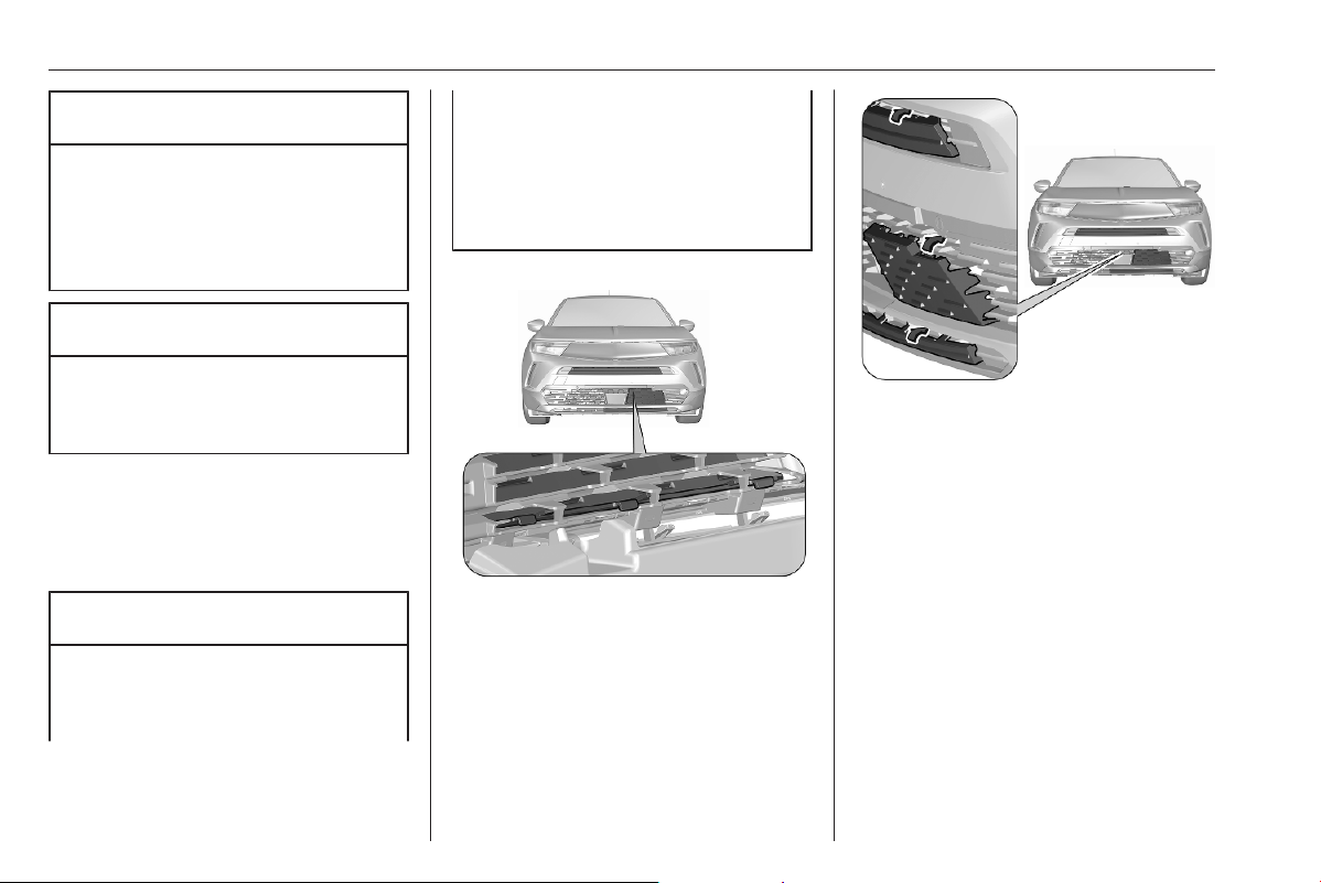
246 Vehicle care
Caution
Access to the diagnostic socket
associated with the on-board
electronics is reserved for
qualified technicians and
approved tools.
Caution
When transporting the vehicle on
a train or on a recovery vehicle, the
mud flaps might be damaged.
Cold protection covers
It is recommended to have the cold
protection covers installed by a
workshop.
Caution
The cold protection covers must
be removed when one of the
following conditions occurs:
● The ambient temperature is
above 10 °C.
● The vehicle is towing a trailer.
● The vehicle is driven at speeds
above 75 mph.
Installation
1. Place the lower part of the
respective cold protection cover
on the inside of the grille as
shown.
2. Press from the outside the upper
part of the cold protection covers
against the slat of the grille.
3. Ensure that the cold protection
covers are fixed securely.
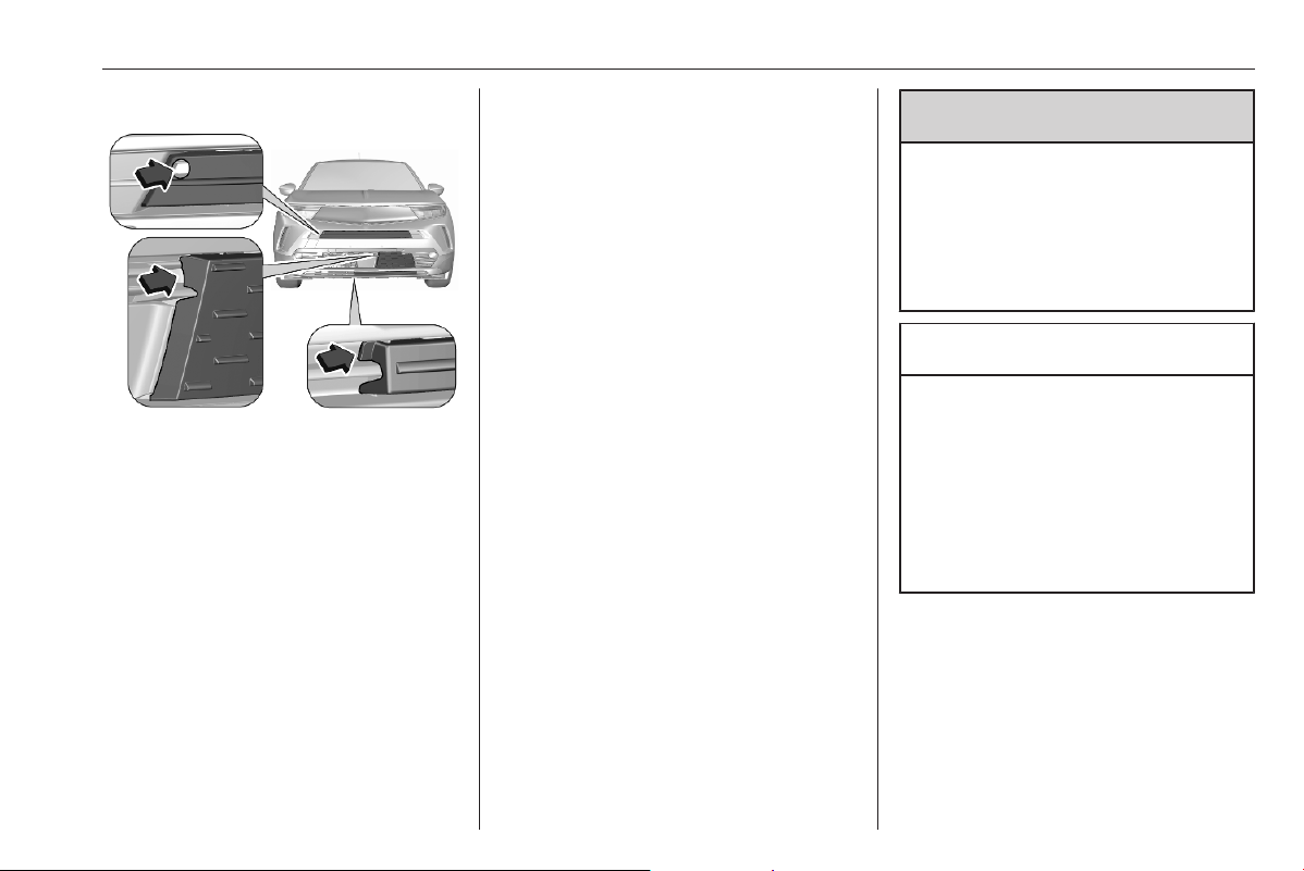
Vehicle care 247
Deinstallation
Remove the cold protection covers by
gently pulling them out at the
indicated positions.
Mobile phones and CB radio
equipment
The vehicle specific installation
instructions and the operating
guidelines of the mobile phone and
hands-free manufacturer must be
observed when installing and
operating a mobile telephone. Failure
to do so could invalidate the vehicle
type approval (EU directive 95/54/
EC).
Recommendations for fault-free
operation:
● Professionally installed exterior
antenna to obtain the maximum
range possible.
● Maximum transmission power
10 W.
● Installation of the phone in a
suitable spot, consider the area
in which the airbag inflates 3 36.
Seek advice on predetermined
installation points for the external
antenna or equipment holder and
ways of using devices with a
transmission power exceeding 10 W.
Use of a hands-free attachment
without external antenna with mobile
telephone standards GSM
900/1800/1900 and UMTS is only
permitted if the maximum
transmission power of the mobile
telephone is 2 W for GSM 900 or
1 W for the other types.
For reasons of safety, do not use the
phone while driving. Even use of a
hands-free set can be a distraction
while driving.
9
Warning
Operation of radio equipment and
mobile telephones which fail to
meet above mentioned mobile
telephone standards is only
permitted using an antenna
located outside of the vehicle.
Caution
Mobile telephones and radio
equipment may lead to
malfunctions in the vehicle
electronics when operated inside
the vehicle with no exterior
antenna, unless the above
mentioned regulations are
observed.

248 Vehicle care
Vehicle storage
Storage for a long period of time
If the vehicle is to be stored for several
months:
● Wash the vehicle.
● Have the wax in the engine
compartment and underbody
checked.
● Clean and preserve the rubber
seals.
● Fill up fuel tank completely.
● Change the engine oil.
● Drain the washer fluid reservoir.
● Check the coolant antifreeze and
corrosion protection.
● Adjust tyre pressure to the value
specified for full load.
● Park the vehicle in a dry, well
ventilated place. Engage first or
reverse gear or set selector lever
to P. Prevent the vehicle from
rolling.
● Do not apply the parking brake.
● Open the bonnet, close all doors
and lock the vehicle.
Storage for a long period of time
(BEV)
If the vehicle is to be stored for several
months:
● Wash the vehicle.
● Have the wax in the engine
compartment and underbody
checked.
● Clean and preserve the rubber
seals.
● Drain the washer fluid reservoir.
● Check the coolant antifreeze and
corrosion protection.
● Adjust tyre pressure to the value
specified for full load.
● Park the vehicle in a dry, well
ventilated place. Engage first or
reverse gear or set selector lever
to P. Prevent the vehicle from
rolling.
● Do not apply the parking brake.
● Open the bonnet, close all doors
and lock the vehicle.
Up to four weeks
Plug in the charging cable.
Four weeks to twelve months
● Discharge the high voltage
battery until 30 percent remain on
the battery range indicator
(battery symbol) on the Driver
Information Centre.
● Do not plug in the charging cable.
● Always store the vehicle in a
place with temperatures between
−10 °C and 30 °C.
● Vehicle storage at extreme
temperatures may cause
damage to the high voltage
battery.
● Remove the black negative (−)
cable from the 12 V vehicle
battery and attach a trickle
charger to the vehicle battery
terminals or keep the 12 V
vehicle battery cables connected
and trickle charge from the
positive (+) and negative (−)
terminals in the engine
compartment.
● Every three months, check the
battery's state of charge. If the
state of charge is below 30
percent, recharge the battery to
30 percent.

Vehicle care 249
Putting back into operation
When the vehicle is to be put back into
operation:
● Connect the clamp to the
negative terminal of the vehicle
battery. Initialise the power
windows 3 23.
● Check tyre pressure.
● Fill up the washer fluid reservoir.
● Check the engine oil level.
● Check the coolant level.
● Fit the number plate if necessary.
Putting back into operation (BEV)
When the vehicle is to be put back into
operation:
● Connect the clamp to the
negative terminal of the vehicle
battery. Initialise the power
windows 3 23.
● Check tyre pressure.
● Fill up the washer fluid reservoir.
● Check the coolant level.
● Fit the number plate if necessary.
Propulsion types 3 4.
End-of-life vehicle recovery
Information on end-of-life vehicle
recovery centres and the recycling of
end-of-life vehicles is available on our
website, where legally required. Only
entrust this work to an authorised
recycling centre.
High voltage battery
The high voltage battery is designed
for the life of the vehicle if the
recommendations are followed. If it
becomes necessary to replace the
high voltage battery, contact a
workshop for instructions on its
disposal. Improper disposal carries
the risk of severe burns, electric
shock, and damage to the
environment.
Recommendations 3 257.
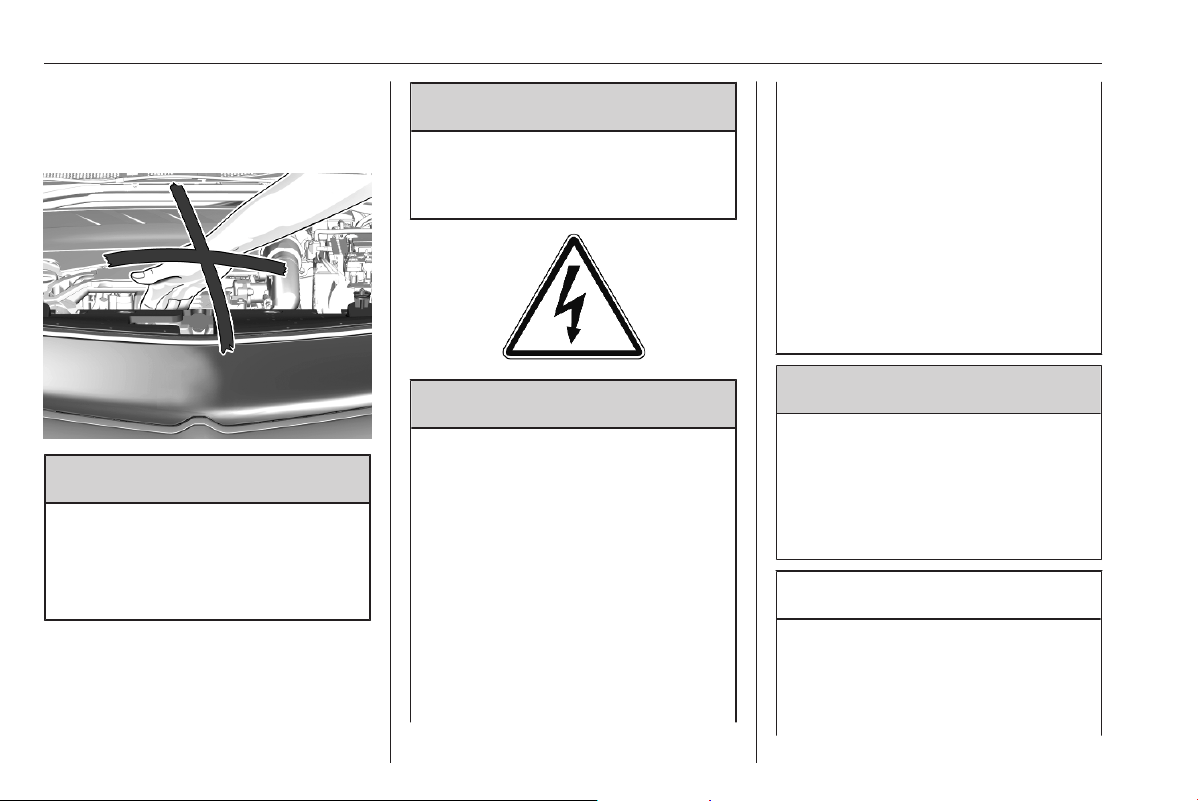
250 Vehicle care
Vehicle checks
Performing work
9 Warning
Only perform engine compartment
checks when the ignition is off.
The cooling fan may start
operating even if the ignition is off.
9 Danger
The ignition system uses
extremely high voltage. Do not
touch.
9 Danger
Electric or Hybrid versions:
Never try to perform maintenance
work on high voltage components
yourself. You may be injured and
the vehicle may be damaged.
Service and repair of these high
voltage components should only
be performed by a trained service
technician with proper knowledge
and tools. Exposure to high
voltage may cause shock, burns,
and even death. The high voltage
components in the vehicle can
only be serviced by technicians
with special training.
High voltage components are
identified by labels. Do not
remove, open, take apart, or
modify these components. High
voltage cable or wiring has orange
covering. Do not probe, tamper
with, cut, or modify high voltage
cable or wiring.
9 Warning
Electric or Hybrid versions:
Only perform engine compartment
checks when the vehicle is off.
The cooling fan may start
operating even if the vehicle is off.
Caution
Electric or Hybrid versions:
Even small amounts of
contamination to the liquids can
cause damage to vehicle systems.
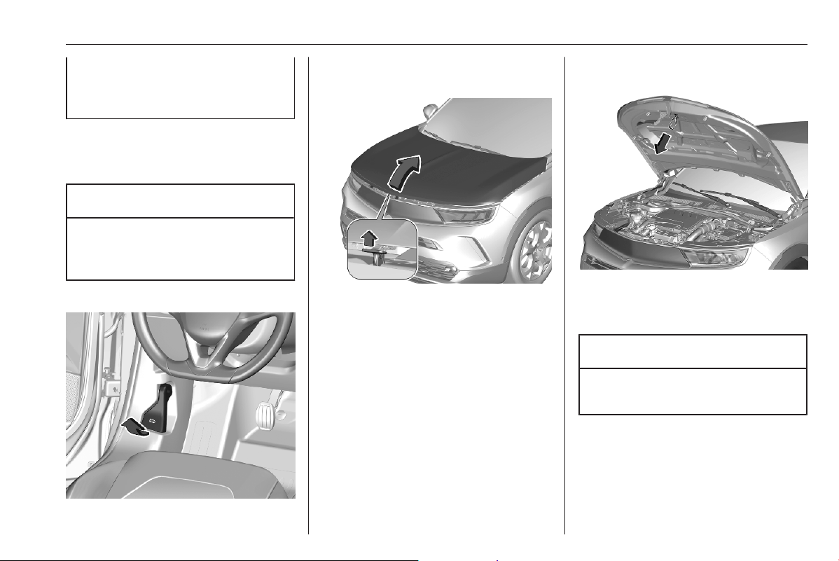
Vehicle care 251
Do not allow contaminants to
contact the fluids, reservoir caps,
or dipsticks.
Bonnet
Opening
Caution
Before opening the bonnet,
deactivate the stop-start system
3 167
Open the driver's door.
Pull the release lever and return it to
its original position.
Push the safety catch upwards and
open the bonnet.
Closing
Lower the bonnet and let it fall into the
latch from a low height (20-25 cm).
Check that the bonnet is engaged.
Caution
Do not press the bonnet into the
latch to avoid dents.
Engine oil
Check the engine oil level manually
on a regular basis to prevent damage
to the engine. Ensure that the correct
specification of engine oil is used.
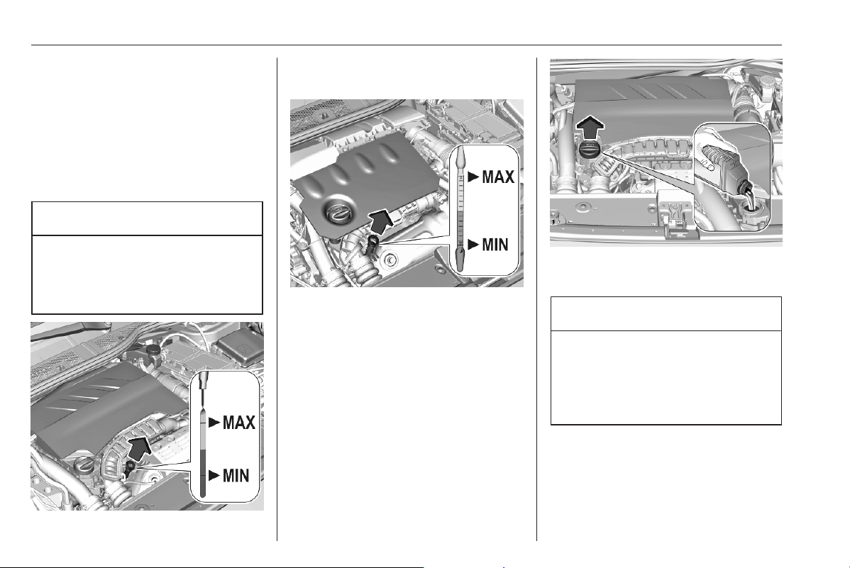
252 Vehicle care
Recommended fluids and lubricants
3 283.
The maximum engine oil
consumption is 0.6 l per 600 miles.
Check with the vehicle on a level
surface. The engine must be at
operating temperature and switched
off for at least 5 min.
Caution
It is the owner's responsibility to
maintain the proper level of an
appropriate quality oil in the
engine.
Different dipsticks are used
depending on engine variant.
Pull out the dipstick, wipe it clean,
reinsert it fully, pull out and read the
engine oil level.
When the engine oil level has
dropped to the MIN mark, top up the
engine oil.
We recommend the use of the same
grade of engine oil that was used at
last change.
The engine oil level must not exceed
the MAX mark on the dipstick.
Caution
Overfilled engine oil must be
drained or suctioned out. If the oil
exceeds the maximum level, do
not start the vehicle and contact a
workshop.
Capacities 3 290.
Fit the cap on straight and tighten it.
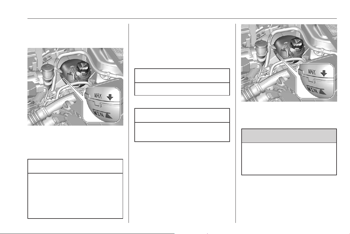
Vehicle care 253
Engine coolant
Coolant level BEV
If the coolant level is at the MIN mark
or below, seek the assistance of a
workshop to have the engine coolant
topped up.
Caution
Using the wrong engine coolant
can cause severe damages to the
high voltage battery. Only
experienced mechanics are
allowed to open the coolant
reservoir and to top up coolant.
Propulsion types 3 4.
Coolant level ICE
The factory filled coolant provides
freeze protection down to approx.
-37 °C.
Caution
Only use approved antifreeze.
Coolant and antifreeze 3 283.
Caution
Too low a coolant level can cause
engine damage.
If the cooling system is cold, the
coolant level should be above the
MIN mark. Top up if the level is low.
9 Warning
Allow the engine to cool before
opening the cap. Carefully open
the cap, relieving the pressure
slowly.
To top up, use a 1:1 mixture of
released coolant concentrate mixed
with clean tap water. If no coolant
concentrate is available, use clean
tap water. Install the cap tightly. Have
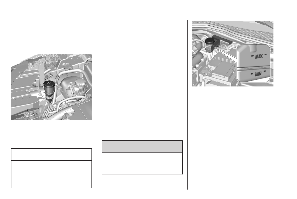
254 Vehicle care
the coolant concentration checked
and have the cause of the coolant
loss remedied by a workshop.
Washer fluid
Fill with clean water mixed with a
suitable quantity of approved
windscreen washer fluid which
contains antifreeze.
Caution
Only washer fluid with a sufficient
antifreeze concentration provides
protection at low temperatures or
a sudden drop in temperature.
Washer fluid 3 283.
Brakes
Depending on the driving style, the
brake wear may vary significantly.The
brake wear may increase when the
vehicle is driven over short distances,
e.g. in the city.
It may be necessary to have the
condition of the brakes checked, even
between vehicle services.
Unless there is a leak in the circuit, a
drop in the brake fluid level indicates
that the brake pads are worn.
Once new brake linings are installed,
do not brake unnecessarily hard for
the first few journeys.
Brake fluid
9 Warning
Brake fluid is poisonous and
corrosive. Avoid contact with eyes,
skin, fabrics and painted surfaces.
The brake fluid level must be between
the MIN and MAX marks.
If fluid level is below MIN seek the
assistance of a workshop.
Brake and clutch fluid 3 283.
Vehicle battery
The vehicle battery is maintenance-
free provided that the driving profile
allows sufficient charging of the
battery. Short-distance-driving and
frequent engine starts can discharge
the battery. Avoid the use of
unnecessary electrical consumers.
Vehicle care 255
Batteries do not belong in household
waste. They must be disposed of at
an appropriate recycling collection
point.
Laying up the vehicle for more than
four weeks can lead to battery
discharge. Disconnect the clamp from
the negative terminal of the vehicle
battery.
Ensure the ignition is switched off
before connecting or disconnecting
the vehicle battery.
Battery discharge protection 3 92.
Replacing the vehicle battery
Notice
Any deviation from the instructions
given in this section may lead to
temporary deactivation or
disturbance of the stop-start system.
When the vehicle battery is being
replaced, please ensure that there
are no open ventilation holes in the
vicinity of the positive terminal. If a
ventilation hole is open in this area, it
must be closed off with a dummy cap,
and the ventilation in the vicinity of the
negative terminal must be opened.
Ensure that the battery is always
replaced by the same type of battery.
The vehicle battery has to be
replaced by a workshop.
Stop-start system 3 167.
Charging the vehicle battery
9 Warning
On vehicles with stop-start
system, ensure that the charging
potential does not exceed 14.6 V
when using a battery charger.
Otherwise the vehicle battery may
be damaged.
Jump starting 3 273.
Discharge protection
Battery voltage
When the vehicle battery voltage is
running low, a warning message will
appear in the Driver Information
Centre.
When the vehicle is being driven, the
load reduction function temporarily
deactivates certain functions, such as
the air conditioning, the heated rear
window, heated steering wheel, etc.
The deactivated functions are
reactivated automatically as soon as
conditions permit.
Idle boost
If charging of the vehicle battery is
required due to battery condition, the
power output of the generator must
be increased. This will be achieved by
an idle boost which may be audible.
A message appears in the Driver
Information Centre.
Power outlet
The power outlets are deactivated in
the event of low vehicle battery
voltage.

256 Vehicle care
Warning label
Meaning of symbols:
● No sparks, naked flames or
smoking.
● Always shield eyes. Explosive
gases can cause blindness or
injury.
● The vehicle battery contains
sulphuric acid which could cause
blindness or serious burn
injuries.
● Keep the vehicle battery out of
reach of children.
● See the Owner's Manual for
further information.
● Explosive gas may be present in
the vicinity of the vehicle battery.
Power saving mode
This mode deactivates electrical
consumers to avoid excessive
discharging of the vehicle battery.
These consumers, such as the
Infotainment system, windscreen
wipers, low beam headlights,
courtesy light, etc. can be used for a
total maximum time of about
40 minutes after ignition is switched
off.
Changing into power saving mode
When power saving mode is
activated, a message appears in the
Driver Information Centre.
An active telephone call using the
hands-free option will be maintained
for around 10 minutes longer.
Deactivating power saving mode
Power saving mode is deactivated
automatically when the engine is
restarted. Run the engine for a
sufficient charge:
● for less than 10 minutes to use
the consumers for approx.
5 minutes
● for more than 10 minutes to use
the consumers for up to approx.
30 minutes
Heating functionalities
Notice
Individual heating functionalities,
such as heated seats or heated
steering wheel, may be temporarily
unavailable in the event of electrical
loading constraints. Functions will
be resumed after some minutes.

Vehicle care 257
High voltage battery
To preserve the range and the
durability of the high voltage battery,
the following is recommended:
● Whenever possible do not
charge the high voltage battery
more than 80%.
● Do not completely discharge the
high voltage battery.
● Do not store the vehicle for a long
period of non-use (more than 12
hours) when the high voltage
battery has a low or high charge
level. Prefer a charge level
between 20 and 40%.
● Limit the use of fast charging.
● Do not expose the vehicle to
temperatures below -30 °C and
above 60 °C for more than 24
hours.
● Avoid charging the vehicle at low
temperatures (except if the
vehicle ran more than 20
minutes) or above 30 °C.
● Do not use the high voltage
battery as a generator of energy.
● Do not use a generator to
recharge the high voltage
battery.
Vehicle storage 3 248.
Leakage
Damage to the high voltage battery
could result in the leakage of toxic
gases or fluids either immediately or
later. The following is recommended:
● Always inform the fire and
emergency services in the event
of an incident, that the vehicle is
equipped with a high voltage
battery.
● Never touch the liquids leaking
from the high voltage battery.
● Do not inhale the gases emitted
by the high voltage battery which
are toxic.
● Move away from the vehicle in
the event of incident or accident,
the gases emitted being
flammable and could cause a
fire.
● Too low a coolant level must be
topped up and the cause of the
coolant loss remedied by a
workshop.
Diesel fuel system bleeding
If the tank has been run dry, the diesel
fuel system must be bled. Refuel at
least five litres diesel. Switch on the
ignition for about 60 seconds and
switch off again. Then crank the
engine. If the engine does not start
directly, repeat this process a few
times. If the engine then fails to start,
seek the assistance of a workshop.
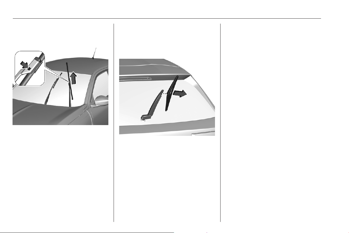
258 Vehicle care
Wiper blade replacement
Windscreen
Switch off ignition.
Within one minute after switching off
ignition, operate the wiper lever to
position the wiper blades vertically on
the windscreen.
Lift the wiper arm until it stays in the
raised position, press button to
disengage the wiper blade and
remove.
Attach the new wiper blade to the
wiper arm and push until it engages.
Lower wiper arm carefully.
To return the wiper arms to their
original position, switch on the ignition
and operate the wiper lever.
Rear window
Lift wiper arm. Disengage wiper blade
as shown in illustration and remove.
Attach the wiper blade slightly angled
to the wiper arm and push until it
engages.
Lower wiper arm carefully.
Bulb replacement
Before replacing a bulb, ensure that
all exterior and interior lights and the
ignition are switched off.
Only hold a new bulb at the base. Do
not touch the bulb glass with bare
hands.
Use only the same bulb type for
replacement.
Bulb check
After a bulb replacement switch on
the ignition, operate and check the
lights.
LED headlights
Headlights for low and high beam,
daytime running lights and turn lights
are designed as LEDs and cannot be
changed.
Have lights repaired by a workshop in
case of failure.
Front fog lights
Have lights repaired by a workshop in
case of failure.
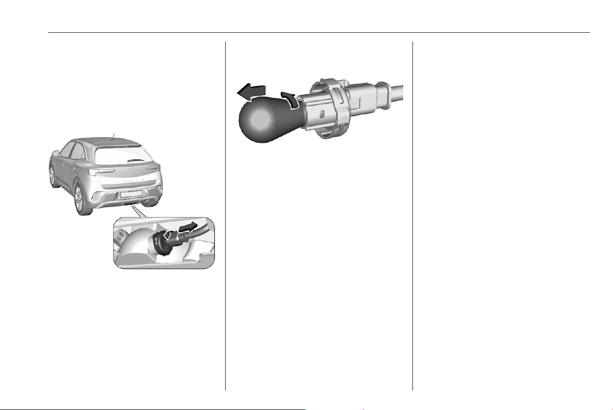
Vehicle care 259
Tail lights
LED tail lights
Have lights repaired by a workshop in
case of failure.
Rear fog light
1. Turn the bulb holder anticlockwise
and remove it from the reflector
housing.
2. Slightly press down the bulb, turn
it anticlockwise and remove it
from the socket.
3. Replace and insert the new bulb
into socket by turning clockwise.
4. Insert the bulb socket into the
reflector and turn clockwise.
Centre high-mounted brake light
Have lights repaired by a workshop in
case of failure.
Bulb check
Switch on the ignition, operate and
check all lights.
Number plate light
Have lights repaired by a workshop in
case of failure.
Interior lights
Have the following bulbs replaced by
a workshop:
● courtesy light, reading lights
● load compartment light
● instrument panel illumination
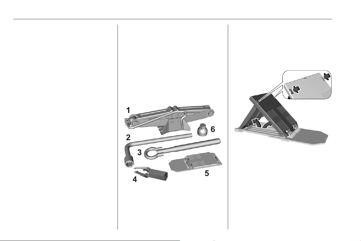
260 Vehicle care
Electrical system
Fuses
A defective fuse must be replaced by
a workshop.
Vehicle tools
Tools
The vehicle tools are either located in
a toolbag on the carpet, in a toolbox
under the carpet or in a box below the
floor cover in the load compartment.
Vehicles with spare wheel
Open the load compartment.
The tools are located either in the
toolbag on the carpet or in the toolbox
under the carpet:
● Jack (1)
● Wheel wrench (2)
● Towing eye (3)
● Wheel bolt cover remover (4)
● Chock (5)
● Adapter for the locking wheel
nuts (6)
To use the chock, fold apart and stick
together.
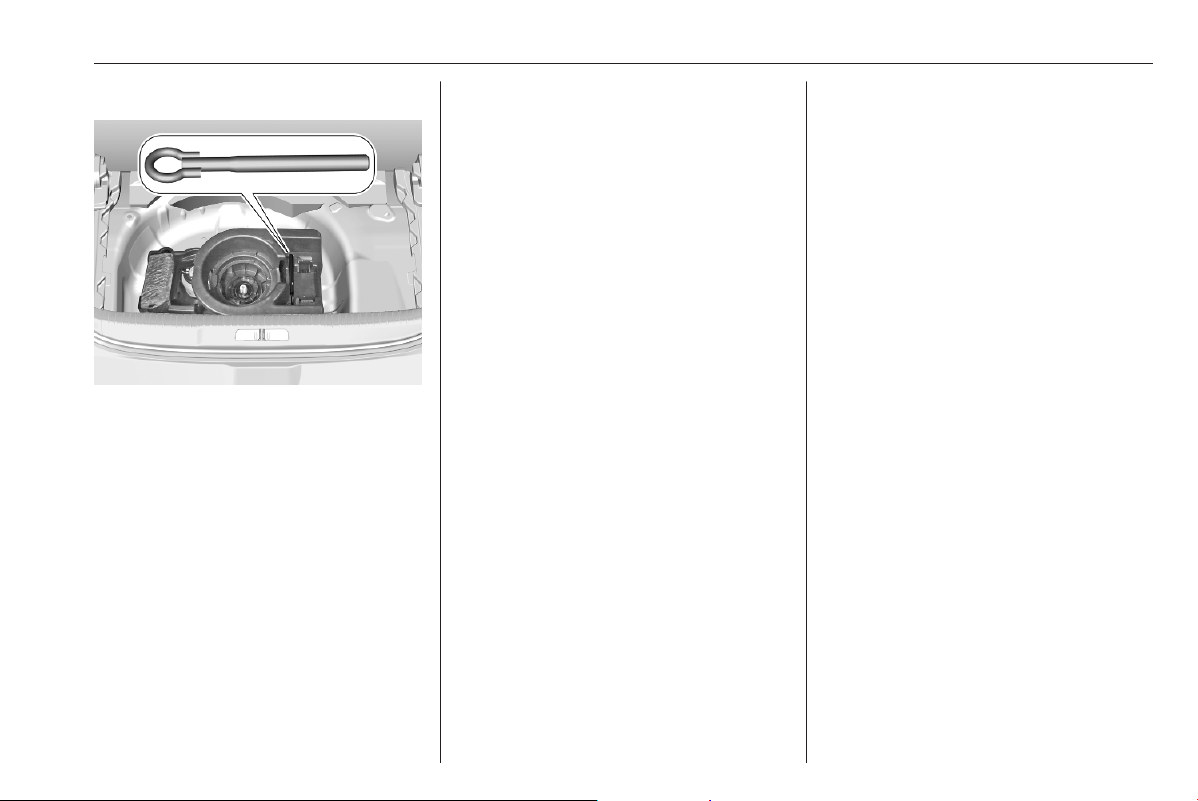
Vehicle care 261
Vehicles without spare wheel
The towing eye is located in a box
below the floor cover in the load
compartment.
Tyre repair kit 3 265.
Wheels and tyres
Tyre condition, wheel condition
Drive over edges slowly and at right
angles if possible. Driving over sharp
edges can cause tyre and wheel
damage. Do not trap tyres on the kerb
when parking.
Regularly check the wheels for
damage. Seek the assistance of a
workshop in the event of damage or
unusual wear.
Winter tyres
Winter tyres improve driving safety at
temperatures below 7 °C and should
therefore be fitted on all wheels.
In accordance with country-specific
regulations, affix the speed sticker in
the driver's field of view, if the tyre
speed code is below the maximum
speed of the vehicle.
All tyre sizes are permitted as winter
tyres 3 291.
Tyre designations
E.g. 225/55 R 18 98 V
225 : tyre width, mm
55 : cross-section ratio (tyre height
to tyre width), %
R : belt type: Radial
RF : type: RunFlat
18 : wheel diameter, inches
98 : load index e.g. 98 is equivalent
to 750 kg
V : speed code letter
Speed code letter:
Q : up to 100 mph
S : up to 112 mph
T : up to 118 mph
H : up to 130 mph
V : up to 150 mph
W : up to 168 mph
Choose a tyre appropriate for the
maximum speed of your vehicle.
The maximum speed is achievable at
kerb weight with driver (75 kg) plus
125 kg payload. Optional equipment
could reduce the maximum speed of
the vehicle.
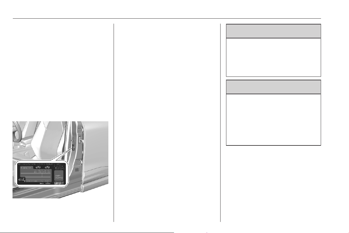
262 Vehicle care
Directional tyres
Directional tyres should be mounted
so that they rotate in the correct
direction. The proper rotation
direction is indicated by a symbol
(e.g. an arrow) on the sidewall.
Tyre pressure
Check the pressure of cold tyres at
least every 14 days and before any
long journey. Do not forget the spare
wheel. This also applies to vehicles
with tyre deflation detection system.
The tyre pressure information label
on the left B-pillar indicates the
original equipment tyres and the
correspondent tyre pressures.
The tyre pressure data refers to cold
tyres. It applies to summer and winter
tyres.
Always inflate the spare tyre to the
pressure specified for full load.
Incorrect tyre pressures will impair
safety, vehicle handling, comfort and
fuel economy and will increase tyre
wear.
The driver is responsible for correct
adjustment of tyre pressure.
The tyre pressure tables show all
possible tyre combinations 3 291.
For the tyres approved for your
vehicle, refer to the EEC Certificate of
Conformity provided with your vehicle
or other national registration
documents.
Tyre pressures differ depending on
various options. For the correct tyre
pressure value, identify the
respective tyre in the tyre pressure
table 3 291 or on the tyre pressure
information label as described before.
9
Warning
If the pressure is too low, this can
result in considerable tyre warm-
up and internal damage, leading to
tread separation and even to tyre
blow-out at high speeds.
9 Warning
For specific tyres the
recommended tyre pressure as
shown in the tyre pressure table
may exceed the maximum tyre
pressure as indicated on the tyre.
Never exceed the maximum tyre
pressure as indicated on the tyre.
Temperature dependency
The tyre pressure depends on the
temperature of the tyre. During
driving, tyre temperature and
pressure increase. Tyre pressure
values provided on the tyre
information label and tyre pressure
chart are valid for cold tyres, which
means at 20 °C.

Vehicle care 263
The pressure increases by nearly
1.5 psi for a 10 °C temperature
increase. This must be considered
when warm tyres are checked.
Tyre deflation detection
system
The tyre deflation detection system
continually checks the rotation speed
of all four wheels and warns on low
tyre pressure condition once vehicle
is driving. This is achieved by
comparing tyre rolling circumference
with reference values and further
signals.
If a tyre loses pressure the control
indicator w illuminates and a warning
message is displayed in the Driver
Information Centre.
Control indicator w 3 74.
In this case reduce speed, avoid
sharp cornering and strong braking.
Stop at next safe opportunity and
check tyre pressure.
After adjusting tyre pressure initialise
system to extinguish the control
indicator and restart system.
If the failure continues to be
displayed, contact a workshop. The
system is inoperable when the ABS or
Electronic Stability Control has a
malfunction or a temporary spare
wheel is used. Once the tyre has been
refitted, check the tyre pressure with
cold tyres and initialise the system.
Caution
Deflation detection system warns
just about low tyre pressure
condition and does not replace
regular tyre maintenance by the
driver.
System initialisation
After tyre pressure correction or
wheel change, the system must be
initialised to learn new circumference
reference values:
1. Always ensure that all four tyres
have correct tyre pressure
3 291.
2. Apply parking brake.
3. Initialise the system via the Info
Display 3 78.
4. Reset is confirmed by pop-up
indication.
After initialisation system
automatically calibrates to new tyre
pressures during driving. After longer
drive the system will adopt and
monitor new pressures.
Always check tyre pressure with cold
tyres.
System has to be reinitialised when:
● Tyre pressure has been changed
● Load condition has been
changed
● Wheels have been swapped or
exchanged
The system will not warn
instantaneously on a tyre blow out or
a rapid deflation. This is due to
required calculation time.
Tread depth
Check tread depth at regular
intervals.
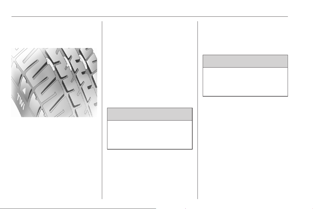
264 Vehicle care
For safety reasons, it is
recommended that the tread depth of
the tyres on one axle should not vary
by more than 2 mm.
The legally permissible minimum
tread depth (1.6 mm) has been
reached when the tread has worn
down as far as one of the tread wear
indicators (TWI). Their position is
indicated by markings on the
sidewall.
If there is more wear at the front than
the rear, swap round front wheels and
rear wheels periodically. Ensure that
the direction of rotation of the wheels
remains the same.
Tyres age, even if they are not used.
We recommend tyre replacement
every 6 years.
Changing tyre and wheel
size
If tyres of a different size than those
fitted at the factory are used, it may be
necessary to reprogramme the tyre
deflation detection system and make
other vehicle modifications.
Have the label with tyre pressures
replaced.
9 Warning
The use of unsuitable tyres or
wheels may lead to accidents and
will invalidate the vehicle
operating permit.
Wheel covers
Wheel covers and tyres that are
factory approved for the respective
vehicle and comply with all of the
relevant wheel and tyre combination
requirements must be used.
If the wheel covers and tyres used are
not factory approved, the tyres must
not have a rim protection ridge.
Wheel covers must not impair brake
cooling.
9 Warning
Use of unsuitable tyres or wheel
covers could lead to sudden
pressure loss and thereby
accidents.
Vehicles with steel wheels: When
using locking wheel nuts, do not
attach wheel covers.
Spare wheels: Do not use wheel
covers.
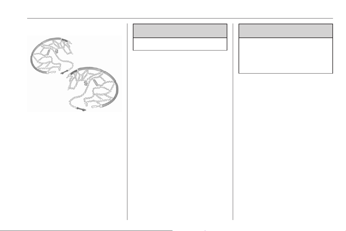
Vehicle care 265
Tyre chains
Tyre chains are only permitted on the
front wheels.
Only use tryre chains designed to be
used with tyre type of the vehicle:
● For 16 inch and 17 inch tyres,
only use Polaire XP9 120 (9mm)
tyre chains.
● For 18 inch tyres, only use
Polaire 0112 PSSD tyre chains.
Notice
The use of tyre chains and the
maximum allowed speed is
regulated by country-specific
legislation.
9
Warning
Damage may lead to tyre blowout.
When fitting the tyre chains follow the
instructions provided by the
manufacturer of the tyre chains.
After having fitted the tyre chains,
stop the vehicle after having driven a
short distance and make sure that the
tyre chains are correctly tightened.
Temporary spare wheel
The use of tyre chains is not permitted
on the temporary spare wheel.
Tyre repair kit
Minor damage to the tyre tread can be
repaired with the tyre repair kit.
Do not remove foreign bodies from
the tyres.
Tyre damage exceeding 4 mm or that
is at tyre's sidewall cannot be repaired
with the tyre repair kit.
Depending on version, there are two
different tyre repair kits (Type A and
Type B).
9
Warning
Do not drive faster than 50 mph.
Do not use for a lengthy period.
Steering and handling may be
affected.
In the case of a flat tyre:
Apply the parking brake and engage
first gear, reverse gear or P.
The tyre repair kit is in the load
compartment below the floor cover.
1. Remove the sealant bottle and the
compressor.
2. Pull speed limit label from sealant
bottle and place it in driver's
visible area.
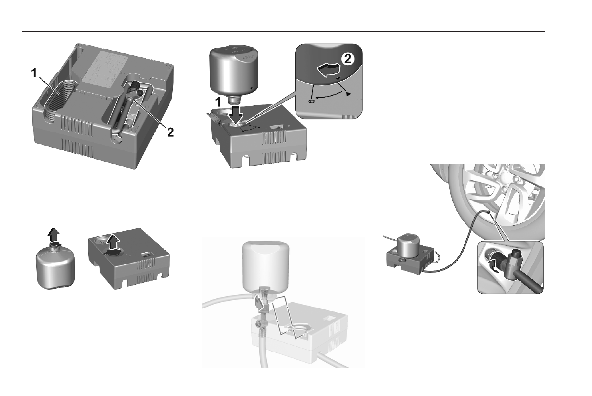
266 Vehicle care
3. Remove the electrical connection
cable (1) and air hose (2) from the
stowage compartments on the
underside of the compressor.
4. Type A: Open sealant bottle and
lift the lid.
5. Type A: First, insert sealant bottle
into the compresor and align the
triangle symbols. Then, push
down sealant bottle and turn it to
the lock position.
Type B: Screw the compressor air
hose to the connection on the
sealant bottle.
6. Type B: Fit the sealant bottle into
the bracket on the compressor.
7. Set the compressor near the tyre
in such a way that the sealant
bottle is upright.
8. Unscrew valve cap from defective
tyre.
9. Screw the filler hose to the tyre
valve.
10. The switch on the compressor
must be set to J.
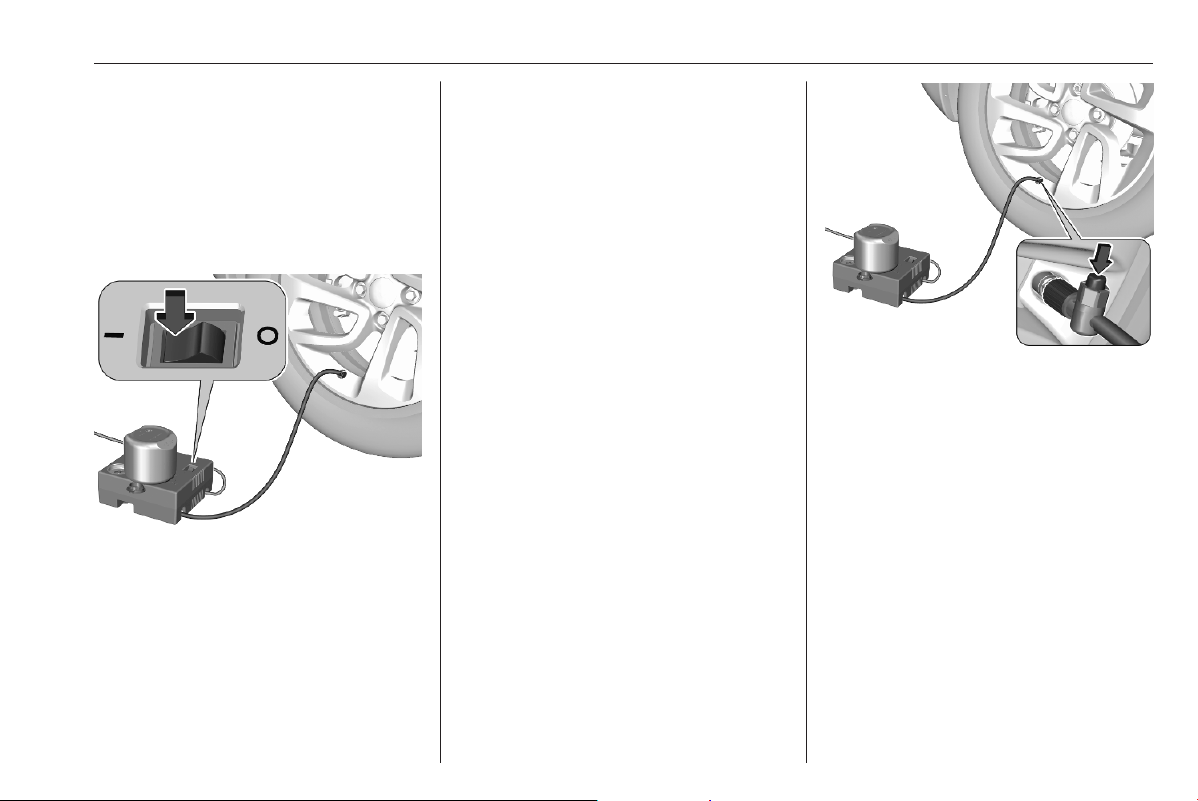
Vehicle care 267
11. Connect the compressor plug to
the 12 V power outlet or cigarette
lighter socket 3 61.
To avoid discharging the vehicle
battery, we recommend to use the
tyre repair kit only when the
combustion engine is running or
when the electric engine is ready.
12. Set the rocker switch on the
compressor to I. The tyre is filled
with sealant.
13. The compressor pressure gauge
briefly indicates up to
600 kPa (6 bar) whilst the sealant
bottle is emptying (approx.
30 seconds). Then the pressure
starts to drop.
14. All of the sealant is pumped into
the tyre. Then the tyre is being
inflated.
15. The prescribed tyre pressure
should be obtained within ten
minutes.
Tyre pressure 3 291.
When the correct pressure is
obtained, switch off the
compressor.
If the prescribed tyre pressure is
not obtained within ten minutes,
remove the tyre repair kit. Move
the vehicle one tyre rotation.
Reattach the tyre repair kit and
continue the filling procedure for
10 minutes. If the prescribed tyre
pressure is still not obtained, the
tyre is too badly damaged. Seek
the assistance of a workshop.
Drain excess tyre pressure with
the button on the air hose.
Do not run the compressor longer
than ten minutes.
16. Detach the tyre repair kit. Remove
sealant bottle from compressor.
Screw the filler hose to the free
connection of the sealant bottle.
This prevents sealant from
escaping. Stow tyre repair kit in
load compartment.
17. Remove any excess sealant
using a cloth.
18. Continue driving immediately so
that sealant is evenly distributed
in the tyre. Drive between
13 mph and 37 mph. After driving

268 Vehicle care
approx. 3 miles but no more than
ten minutes, stop and check tyre
pressure. Screw compressor air
hose directly onto tyre valve when
doing this. Fill tyre as described
before. Drain excess tyre
pressure with the button on the air
hose.
If tyre pressure hasn't decreased
under 200 kPa (2 bar), set it to the
correct value. Otherwise the
vehicle must not be used. Seek
assistance of a workshop.
Repeat the checking procedure
once more after driving further
3 miles but no more than ten
minutes to check that there is no
more loss of pressure.
If the tyre pressure has fallen
below 200 kPa (2 bar), the vehicle
must not be used. Seek the
assistance of a workshop.
19. Stow away tyre repair kit in load
compartment.
Notice
The driving characteristics of the
repaired tyre are severely affected,
therefore have this tyre replaced.
If unusual noise is heard or the
compressor becomes hot, turn
compressor off for at least 30 min.
The built-in safety valve opens at a
pressure of seven bar (102 psi).
Note the expiry date of the kit. After
this date its sealing capability is no
longer guaranteed. Pay attention to
storage information on sealant
bottle.
Replace the used sealant bottle.
Dispose of the bottle as prescribed
by applicable laws.
The compressor and sealant can be
used from approx. -30 °C.
Wheel changing
Make the following preparations and
observe the following information:
● Park the vehicle on a level, firm
and non-skid surface. The front
wheels must be in the straight-
ahead position.
● Apply the parking brake and
engage first gear, reverse gear or
P.
● Place a chock under the wheel
diagonally opposite the wheel to
be changed.
● If the ground on which the vehicle
is standing is soft, a solid board
(approx. 1 cm thick) should be
placed under the jack.
● Take heavy objects out of the
vehicle before jacking up.
● No people or animals may be in
the vehicle when it is jacked-up.
● Never crawl under a jacked-up
vehicle.
● Do not start the vehicle when it is
raised on the jack.
● Before screwing in the wheel
bolts, clean them.
9 Warning
Do not grease wheel bolts.
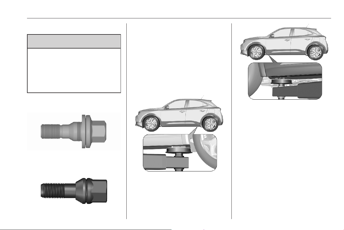
Vehicle care 269
Tightening torques
9 Warning
Ensure to use always the correct
wheel bolts if changing the
wheels. When installing the spare
wheel for temporary usage, the
bolts for alloy wheel rims can also
be used.
Depending on the wheel rim material,
two different bolts are available.
Tightening torque for alloy wheel rims
is 115 Nm.
Tightening torque for steel wheel rims
is 115 Nm.
Use the correct wheel bolts for the
respective wheels.
Jacking positions
The jacking positions shown refer to
the use of lifting arms and accessory
jacks used for changing winter /
summer tyres.
The rear arm position of the lifting
platform is centrically under the
relevant vehicle jacking point.
The front arm position of the lifting
platform is centrically under the
relevant vehicle jacking point.
Spare wheel
The spare wheel can be classified as
a temporary spare wheel depending
on the size compared to the other
mounted wheels and country
regulations. In this case, a
permissible maximum speed applies,
even though no label at the spare
wheel indicates this.
If there is a label on the spare wheel,
the permissible speed still depends
on the country regulations.
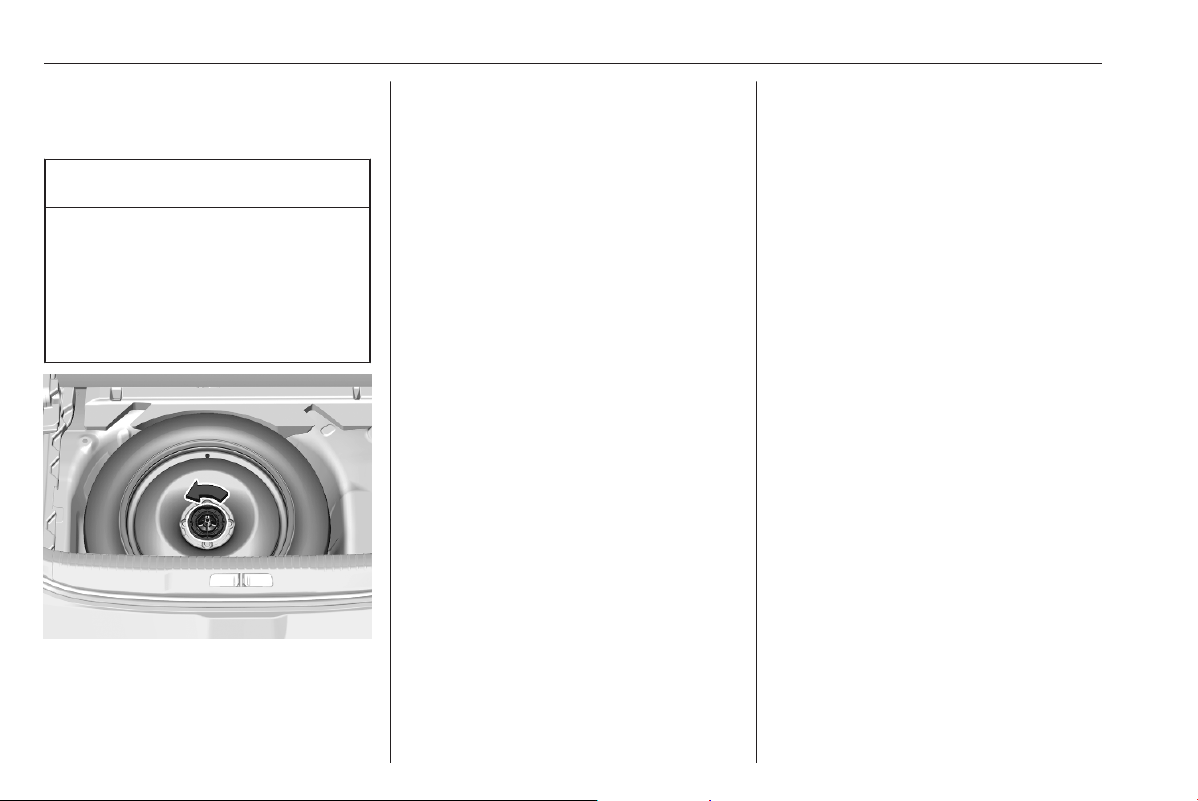
270 Vehicle care
Only mount one temporary spare
wheel. Take curves slowly. Do not
use for a long period of time.
Caution
The use of a spare wheel that is
smaller than the other wheels or in
combination with winter tyres
could affect driveability. Have the
defective tyre replaced as soon as
possible.
The spare wheel is located in the load
compartment beneath the floor
covering.
To remove:
1. Open the floor cover 3 49.
2. The temporary spare wheel is
secured with a wing nut. Unscrew
nut and take out the spare wheel.
3. When, after a wheel change, no
wheel is placed in the spare wheel
well, tighten the wing nut and
close floor cover.
4. After wheel change back to full
size wheel, place the temporary
spare wheel in the well and secure
with the wing nut.
Only mount one temporary spare
wheel. The permissible maximum
speed on the label on the temporary
spare wheel is only valid for the
factory-fitted tyre size.
Fitting the spare wheel
Make the following preparations and
observe the following information:
● Park the vehicle on a level, firm
and non-skid surface. The front
wheels must be in the straight-
ahead position.
● Apply the parking brake and
engage first gear, reverse gear or
P.
● Place a chock under the wheel
diagonally opposite the wheel to
be changed.
● Remove the spare wheel.
● Never change more than one
wheel at once.
● Use the jack only to change
wheels in case of puncture, not
for seasonal winter or summer
tyre change.
● The jack is maintenance-free.
● If the ground on which the vehicle
is standing is soft, a solid board
(approx. 1 cm thick) should be
placed under the jack.
● Take heavy objects out of the
vehicle before jacking up.
● No people or animals may be in
the vehicle when it is jacked-up.
● Never crawl under a jacked-up
vehicle.
● Do not start the vehicle when it is
raised on the jack.
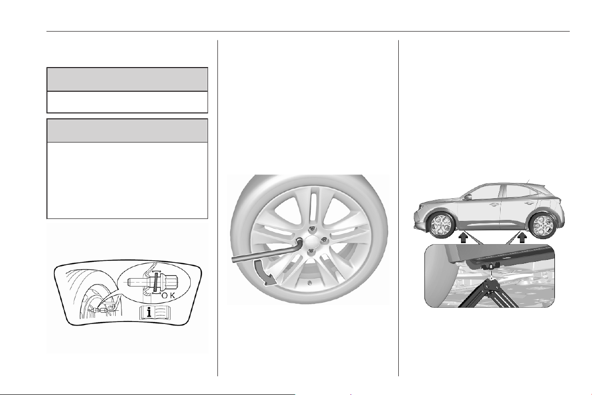
Vehicle care 271
● Before screwing in the wheel
bolts, clean them.
9 Warning
Do not grease wheel bolts.
9 Warning
Ensure to use always the correct
wheel bolts if changing the
wheels. When installing the spare
wheel for temporary usage, the
bolts for alloy wheel rims can also
be used.
● Note that the spare wheel is
secured by the conical contact of
each bolt if the wheel bolts for the
alloy wheel rims are used. In this
case, the washers do not come
into contact with the spare wheel.
1. Disengage wheel bolt caps with
the wheel bolt cover remover.
Vehicle tools 3 260.
Steel wheel rims with cover: Pull
off the wheel cover.
2. Attach the wheel wrench and
loosen each wheel bolt by half a
turn.
The wheels might be protected by
locking wheel nuts. To loosen
these specific nuts first attach the
adapter onto the head of the nut
before installing the wheel
wrench. The adapter is located in
the tool bag.
The wheels might be protected by
locking wheel nuts. To loosen
these specific nuts first attach the
adapter onto the head of the nut
before installing the wheel
wrench. The adapter is located in
the tool bag 3 260.
3. Ensure the jack is correctly
positioned under the relevant
vehicle jacking point.
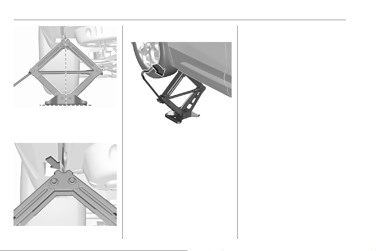
272 Vehicle care
4. Set the jack to the necessary
height. Position it directly below
the jacking point in a manner that
prevents it from slipping.
Ensure that the edge of the body
fits into the notch of the jack.
With the jack correctly aligned,
jack up until wheel is clear of the
ground.
5. Unscrew the wheel nuts.
6. Change the wheel.
7. Screw on the wheel nuts.
8. Lower the vehicle and remove
jack.
9. Install the wheel wrench ensuring
that it is located securely and
tighten each bolt in a crosswise
sequence.
Tightening torque is 115 Nm.
If the vehicle is equipped with
alloy wheel rims, note that the
wheel bolts can also be used for
the spare wheel with steel rims. In
this case, the spare wheel is
secured by the conical contact of
each bolt.
10. Stow the replaced wheel, the
vehicle tools and the adapter for
the locking wheel nuts 3 260.
11. Check the tyre pressure of the
installed tyre and the wheel nut
torque as soon as possible.
Stowing a damaged full size
wheel in the load compartment
The spare wheel well is not designed
for other tyre sizes than the spare
wheel. A damaged full size wheel
must be stowed in the load
compartment and secured properly.
Loading information 3 51.
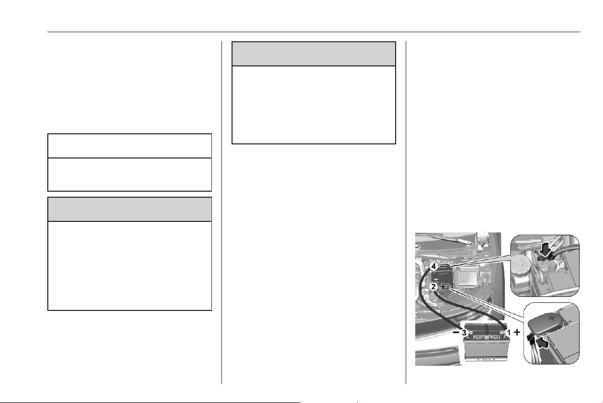
Vehicle care 273
Jump starting
Do not start with quick charger.
A vehicle with a discharged vehicle
battery can be started using jump
leads and the vehicle battery of
another vehicle.
Caution
Never jump start another vehicle
with an electric vehicle.
9 Warning
Be extremely careful when starting
with jump leads. Any deviation
from the following instructions can
lead to injuries or damage caused
by battery explosion or damage to
the electrical systems of both
vehicles.
9 Warning
Avoid contact of the battery with
eyes, skin, fabrics and painted
surfaces. The fluid contains
sulphuric acid which can cause
injuries and damage in the event
of direct contact.
● Never expose the vehicle battery
to naked flames or sparks.
● A discharged vehicle battery can
already freeze at a temperature
of 0 °C. Defrost the frozen battery
before connecting jump leads.
● Wear eye protection and
protective clothing when
handling a battery.
● Use a booster battery with the
same voltage (12 V). Its capacity
(Ah) must not be much less than
that of the discharged vehicle
battery.
● Use jump leads with insulated
terminals and a cross section of
at least 16 mm
2
(25 mm
2
for
diesel engines).
● Do not disconnect the discharged
vehicle battery from the vehicle.
● Switch off all unnecessary
electrical consumers.
● Do not lean over the vehicle
battery during jump starting.
● Do not allow the terminals of one
lead to touch those of the other
lead.
● The vehicles must not come into
contact with each other during
the jump starting process.
● Apply the parking brake,
transmission in neutral,
automatic transmission in P.
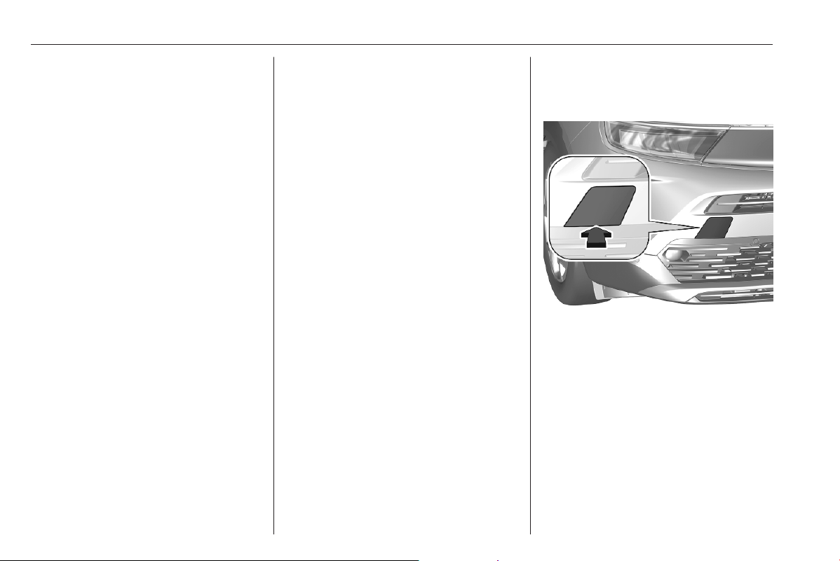
274 Vehicle care
Lead connection order:
1. Connect the red lead to the
positive terminal of the booster
battery.
2. Connect the other end of the red
lead to the positive terminal of the
discharged battery.
3. Connect the black lead to the
negative terminal of the booster
battery.
4. Connect the other end of the black
lead to a vehicle grounding point
of your vehicle in the engine
compartment.
Route the leads so that they cannot
catch on rotating parts in the engine
compartment.
To start the engine:
1. Start the engine of the vehicle
providing the jump.
2. After 5 minutes, start the other
engine. Start attempts should be
made for no longer than
15 seconds at an interval of
1 minute.
3. Allow both engines to idle for
approx. 3 minutes with the leads
connected.
4. Switch on electrical consumers
e.g. headlights, heated rear
window.
5. Reverse above sequence exactly
when removing leads.
Towing
Towing the vehicle
Remove the cap.
The towing eye is stowed with the
vehicle tools 3 260.
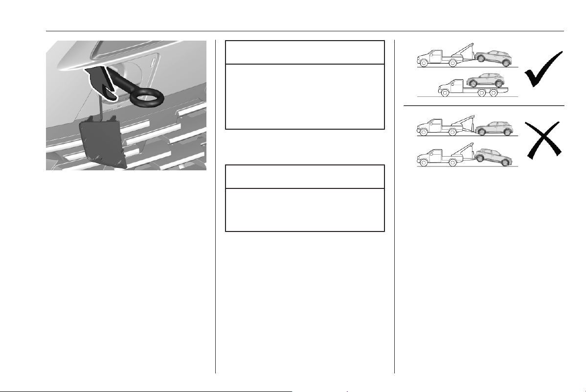
Vehicle care 275
Screw in the towing eye as far as it will
go until it stops in a horizontal
position.
Attach the tow rod to the towing eye.
The towing eye must only be used for
towing and not for recovering the
vehicle.
Switch on ignition to permit operation
of brake lights, horn, windscreen
wiper and, depending on version, to
release the steering wheel lock.
Caution
Deactivate the driver assistance
systems like active emergency
braking 3 200, otherwise the
vehicle may automatically brake
during towing.
Switch the selector lever to neutral.
Release the parking brake.
Caution
Drive slowly. Do not drive jerkily.
Excessive tractive force can
damage the vehicle.
When the engine is not running,
considerably more force is needed to
brake and steer.
To prevent the entry of exhaust gases
from the towing vehicle, switch on the
air recirculation and close the
windows.
When towing a BEV or a vehicle
equipped with an automatic
transmission, transport the vehicle on
a platform or tow it with the front
wheels lifted.
Seek the assistance of a workshop.
After towing, unscrew the towing eye.
Insert cap with the flange into the
recess and fix cap by pushing.
Propulsion types 3 4.
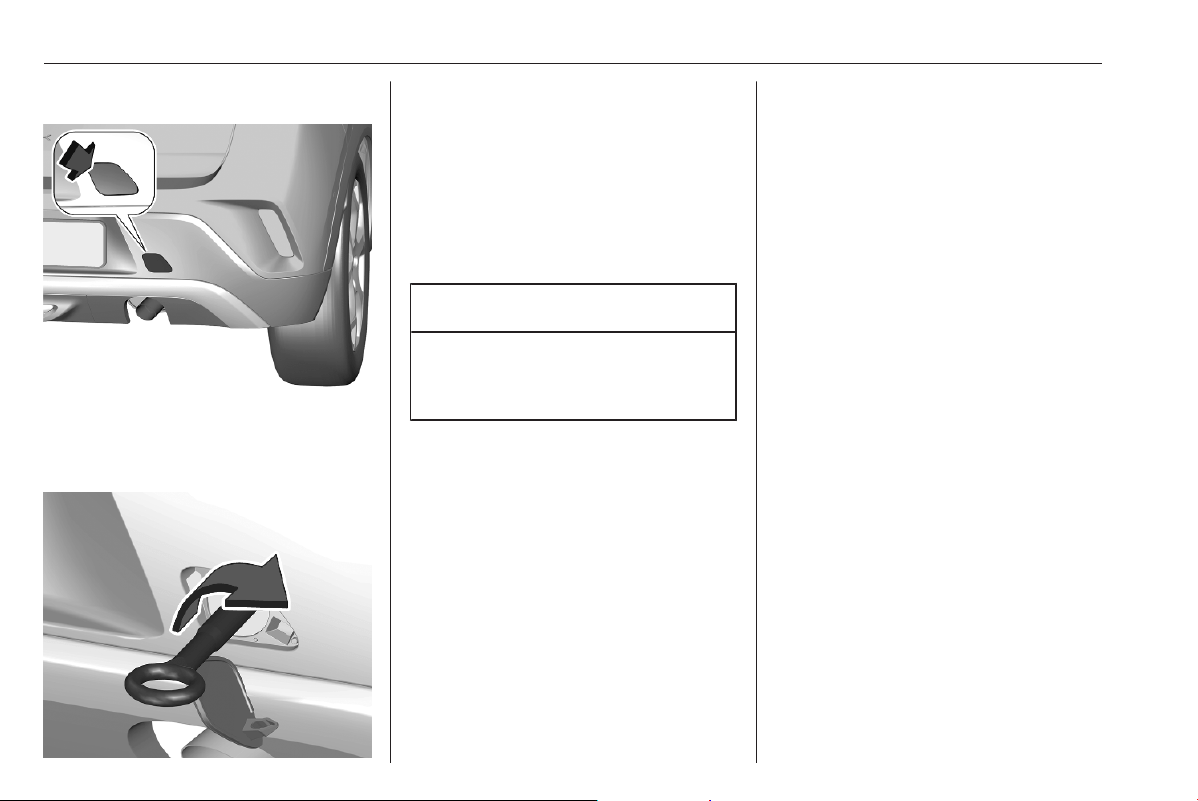
276 Vehicle care
Towing another vehicle
Remove the cap.
The towing eye is stowed with the
vehicle tools 3 260.
Screw in the towing eye as far as it will
go until it stops in a horizontal
position.
Attach a tow rope – or better still a tow
rod – to the towing eye.
The towing eye must only be used for
towing and not for recovering a
vehicle.
Caution
Drive slowly. Do not drive jerkily.
Excessive tractive force can
damage the vehicle.
After towing, unscrew the towing eye.
Insert cap with the upper flange into
the recess and fix cap by pushing.
Appearance care
Exterior care
Locks
The locks are lubricated at the factory
using a high quality lock cylinder
grease. Use a de-icing agent only
when absolutely necessary, as this
has a degreasing effect and impairs
lock function. After using a de-icing
agent, have the locks regreased by a
workshop.
Washing
The paintwork of your vehicle is
exposed to environmental influences.
Bird droppings, dead insects, resin,
pollen and the like should be cleaned
off immediately, as they contain
aggressive constituents which can
cause paint damage.
If using a vehicle wash, comply with
the vehicle wash manufacturer's
instructions. The windscreen wiper
and rear window wiper must be

Vehicle care 277
switched off. Remove antenna and
external accessories such as roof
racks etc.
If you wash your vehicle by hand,
make sure that the insides of the
wheel housings are also thoroughly
rinsed out.
Clean edges and folds on opened
doors and the bonnet as well as the
areas they cover.
Clean bright metal mouldings with a
cleaning solution approved for
aluminium to avoid damages.
Caution
Always use a cleaning agent with
a pH value of 4 to 9.
Do not use cleaning agents on hot
surfaces.
Do not clean the engine compartment
with a steam-jet or high-pressure jet
cleaner.
Thoroughly rinse and leather-off the
vehicle. Rinse leather frequently. Use
separate leathers for painted and
glass surfaces: remnants of wax on
the windows will impair vision.
Have the door hinges of all doors
greased by a workshop.
Exterior lights
Headlight and other light covers are
made of plastic. Do not use any
abrasive or caustic agents, do not use
an ice scraper, and do not clean them
dry.
Polishing and waxing
Polishing is necessary only if the paint
has become dull or if solid deposits
have become attached to it.
Plastic body parts must not be treated
with wax or polishing agents.
Windows and wiper blades
Switch off wipers before handling in
their areas.
Use a soft lint-free cloth or chamois
leather together with window cleaner
and insect remover.
When cleaning the rear window from
inside, always wipe in parallel to the
heating element to prevent damage.
For mechanical removal of ice, use a
sharp-edged ice scraper. Press the
scraper firmly against the glass so
that no dirt can get under it and
scratch the glass.
Clean smearing wiper blades with a
soft cloth and window cleaner. Also
make sure to remove any residues
such as wax, insect residues and
similar from the window.
Ice residues, pollution and continuous
wiping on dry windows will damage or
even destroy the wiper blades.
Wheels and tyres
Do not use high-pressure jet
cleaners.
Clean rims with a pH-neutral wheel
cleaner.
Rims are painted and can be treated
with the same agents as the body.
Paintwork damage
Rectify minor paintwork damage with
a touch-up pen before rust forms.
Have more extensive damage or rust
areas repaired by a workshop.

278 Vehicle care
Underbody
Some areas of the vehicle underbody
have a PVC undercoating while other
critical areas have a durable
protective wax coating.
After the underbody is washed, check
the underbody and have it waxed if
necessary.
Bitumen / rubber materials could
damage the PVC coating. Have
underbody work carried out by a
workshop.
Before and after winter, wash the
underbody and have the protective
wax coating checked.
Towing equipment
Do not clean the coupling ball bar with
a steam-jet or high-pressure jet
cleaner.
Interior care
Interior and upholstery
Only clean the vehicle interior,
including the instrument panel fascia
and panelling, with a dry cloth or
interior cleaner.
Clean the leather upholstery with
clear water and a soft cloth. In case of
heavy soiling, use leather care.
The Driver Information Centre and
the displays should only be cleaned
using a soft damp cloth. If necessary
use a weak soap solution.
Clean fabric upholstery with a
vacuum cleaner and brush. Remove
stains with an upholstery cleaner.
Clothing fabrics may not be
colourfast. This could cause visible
discolourations, especially on light-
coloured upholstery. Removable
stains and discolourations should be
cleaned as soon as possible.
Clean seat belts with lukewarm water
or interior cleaner.
Caution
Close Velcro fasteners as open
Velcro fasteners on clothing could
damage seat upholstery.
The same applies to clothing with
sharp-edged objects, like zips or
belts or studded jeans.
Plastic and rubber parts
Plastic and rubber parts can be
cleaned with the same cleaner as
used to clean the body. Use interior
cleaner if necessary. Do not use any
other agent. Avoid solvents and petrol
in particular. Do not use high-
pressure jet cleaners.
Floor mats
9 Warning
If a floor mat has the wrong size or
is not properly installed, it can
interfere with the accelerator pedal
and/or brake pedal, what can
cause unintended acceleration
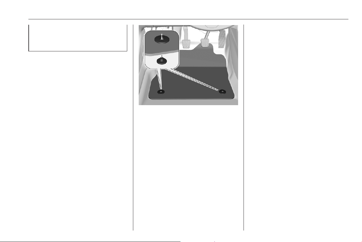
Vehicle care 279
and/or increased stopping
distance which can cause a crash
and injury.
Use the following guidelines for
proper floor mat usage.
● The original equipment floor mats
were designed for this vehicle. If
the floor mats need to be
replaced, it is recommended to
buy certified floor mats which fit
properly and are fixed by the
retainers on the driver side.
Always check that the floor mats
do not interfere with the pedals.
● Use the floor mat with the correct
side up. Do not turn it over.
● Do not place anything on top of
the driver side floor mat.
● Use only a single floor mat on the
driver side.
Inserting floor mats
The driver side floor mat is held in
place by two retainers.
To install:
1. Move the seat backwards as far
as possible.
2. Align slots in the mat with the
retainers, as shown.
3. Push the mat to the floor.
Removing floor mats
To remove:
1. Move the seat backwards as far
as possible.
2. Remove the mat.

280 Service and maintenance
Service and
maintenance
General information ................... 280
Service information .................. 280
Recommended fluids, lubricants
and parts .................................... 283
Recommended fluids and
lubricants ................................ 283
General information
Service information
In order to ensure economical and
safe vehicle operation and to
maintain the value of your vehicle, it
is of vital importance that all
maintenance work is carried out at the
proper intervals as specified.
The detailed, up-to-date service
schedule for your vehicle is available
at the workshop.
Severe operating conditions exist if
one or more of the following
circumstances occur frequently: Cold
starting, stop and go operation, e.g.
for taxis and police vehicles, trailer
operation, mountain driving, driving
on poor and sandy road surfaces,
increased air pollution, presence of
airborne sand and high dust content,
driving at high altitude and large
variations of temperature.
Under these severe operating
conditions, certain service work may
be required more frequently than the
regular service interval indicated in
the service display. Contact a
workshop for customised service
schedules.
Service display 3 66.

Service and maintenance 281
Service intervals
Engine code
EB2LTD,
EB2LTED
EB2ADTD,
EB2ADTS,
EB2ADTSM DV5RCE Electric vehicle
Country group 1 16,000 miles / 1 year 12,500 miles / 1 year
20,000 miles / 1 year
1)
16,000 miles / 2 years
2)
1)
Unless otherwise indicated in the service display.
2)
Initial service interval is 8,000 miles / 1 year
Country Group 1:
Andorra, Austria, Belgium, Cyprus, Denmark, Finland, France, Germany, Greece, Iceland, Italy, Liechtenstein,
Luxembourg, Malta, Monaco, Netherlands, Norway, Portugal, Republic of Ireland, San Marino, Spain, Sweden,
Switzerland, United Kingdom.
Country Group 2:
Bosnia-Herzegovina, Bulgaria, Croatia, Czech Republic, Estonia, Hungary, Latvia, Lithuania, North Macedonia, Poland,
Romania, Slovakia, Slovenia.
Country Group 3:
Albania, Kosovo, Montenegro, New Zealand, Serbia.
Country Group 4:
Israel, Lesotho, South Africa, Swaziland, Turkey.
Country Group 5:
Russia.
Country Group 6:
All other countries which are not listed in the previous country groups.

282 Service and maintenance
Confirmations
Confirmation of service is recorded in the Service and warranty booklet. The date and mileage is completed with the stamp
and signature of the servicing workshop.
Make sure that the Service and warranty booklet is completed correctly as continuous proof of service is essential if any
warranty or goodwill claims are to be met, and is also a benefit when selling the vehicle.

Service and maintenance 283
Recommended fluids,
lubricants and parts
Recommended fluids and
lubricants
Only use products that meet the
recommended specifications.
9 Warning
Operating materials are
hazardous and could be
poisonous. Handle with care. Pay
attention to information given on
the containers.
Engine oil
Engine oil is identified by its quality
and its viscosity. Quality is more
important than viscosity when
selecting which engine oil to use. The
oil quality ensures e.g. engine
cleanliness, wear protection and oil
aging control, whereas viscosity
grade gives information on the oil's
thickness over a temperature range.
Select the appropriate engine oil
based on its quality and on the
minimum ambient temperature
3 287.
Topping up engine oil
Caution
In case of any spilled oil, wipe it up
and dispose it properly.
Engine oils of different manufacturers
and brands can be mixed as long as
they comply with the required engine
oil quality and viscosity.
Use of engine oils for all petrol
engines with only ACEA quality is
prohibited, since it can cause engine
damage under certain operating
conditions.
Select the appropriate engine oil
based on its quality and on the
minimum ambient temperature
3 287.
Additional engine oil additives
The use of additional engine oil
additives could cause damage and
invalidate the warranty.
Engine oil viscosity grades
The SAE viscosity grade gives
information of the thickness of the oil.
Multigrade oil is indicated by two
figures, e.g. SAE 5W-30. The first
figure, followed by a W, indicates the
low temperature viscosity and the
second figure the high temperature
viscosity.
Select the appropriate viscosity grade
depending on the minimum ambient
temperature 3 287.
All of the recommended viscosity
grades are suitable for high ambient
temperatures.
Coolant and antifreeze
Use only antifreeze approved for the
vehicle. Consult a workshop.
The system is factory filled with
coolant designed for excellent
corrosion protection and frost
protection down to approx. -28 °C. In
cold regions with very low
temperatures the factory filled coolant
provides frost protection down to
approx. -37 °C. This concentration
should be maintained all year round.

284 Service and maintenance
The use of additional coolant
additives that intend to give additional
corrosion protection or seal against
minor leaks can cause function
problems. Liability for consequences
resulting from the use of additional
coolant additives will be rejected.
Washer fluid
Use only washer fluid approved for
the vehicle to prevent damage of
wiper blades, paintwork, plastic and
rubber parts. Consult a workshop.
Brake and clutch fluid
Over time, brake fluid absorbs
moisture which will reduce braking
effectiveness. The brake fluid should
therefore be replaced at the specified
interval.
Use only brake fluid approved for the
vehicle. Consult a workshop.
AdBlue
Only use AdBlue to reduce the
nitrogen oxides in the exhaust
emission 3 172.
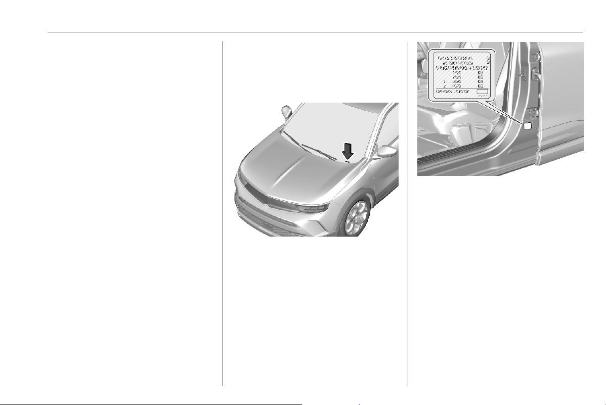
Technical data 285
Technical data
Vehicle identification .................. 285
Vehicle identification number ..285
Identification plate ................... 285
Engine identification ................ 286
Vehicle data ............................... 287
Recommended fluids and
lubricants ................................ 287
Engine data ............................. 288
Vehicle dimensions ................. 289
Capacities ................................ 290
Tyre pressures ........................ 291
Vehicle identification
Vehicle identification
number
The Vehicle Identification Number
may be embossed on the instrument
panel, visible through the windscreen,
or in the engine compartment on the
right body panel.
Identification plate
The identification plate is located on
the front left or right door frame. The
layout and position differ for some
export countries.
Information on identification label:
1 : manufacturer
2 : type approval number
3 : vehicle identification number
4 : permissible gross vehicle weight
rating in kg
5 : permissible gross train weight
in kg
6 : maximum permissible front axle
load in kg
7 : maximum permissible rear axle
load in kg
8 : manufacturer address, vehicle-
specific or country-specific data
The combined total of front and rear
axle loads must not exceed the
permissible gross vehicle weight.

286 Technical data
Vehicle's kerb weight depends on the
specification of the vehicle, e.g.
optional equipment and accessories.
Refer to the EEC Certificate of
Conformity provided with your vehicle
or other national registration
documents.
The technical data is determined in
accordance with European
Community standards. We reserve
the right to make modifications.
Specifications in the vehicle
documents always have priority over
those given in this manual.
Engine identification
The technical data tables show the
engine identifier code.
Engine data 3 288.
To identify the respective engine,
refer to the engine power in the EEC
Certificate of Conformity provided
with your vehicle or other national
registration documents.

Technical data 287
Vehicle data
Recommended fluids and lubricants
Required engine oil quality
Country groups 3 280
Countries included in country groups 1 to 3 and 5
all engines
Vauxhall Original engine oil B71 2010 / B71 2312
Engine EC5F: B71 2290, B71 2296 or B71 300 may also be used.
Engine oil viscosity grades
B71 2010 B71 2312 B71 2302 B71 2297
Engine oil viscosity grade SAE 0W-20 SAE 0W-30 SAE 0W-30 SAE 5W-30

288 Technical data
Engine data
Engine identifier code EB2LTD EB2LTED EB2ADTD EB2ADTS EB2ADTSM DV5RCE Electric vehicle
Sales designation 1.2 T 1.2 T 1.2 T 1.2 T 1.2 T 1.5 D –
Piston displacement [cm
3
]
1199 1199 1199 1199 1199 1499 –
Engine power [kW] 100 74 / 81 74 96 96 81 100 / 115
at rpm 6000 6000 5500 5500 5500 3750 –
Torque [Nm] 230 205 205 230 230 250 260
at rpm 1750 1750 1750 1750 1750 1750 –
Fuel type Petrol Petrol Petrol Petrol Petrol Diesel –
Octane rating RON
1)2)
recommended 95 95 95 95 95 – –
possible 98 98 98 98 98 – –
possible 91 91 91 91 91 – –
Additional fuel type – – – – – – –
1)
A country specific label at the fuel filler flap can supersede the engine specific requirement.
2)
In certain countries, the use of a particular fuel, e.g. a specific octane rating, may be required to ensure proper engine operation.

Technical data 289
Vehicle dimensions
Length [mm] 4151
Width with two exterior mirrors folded [mm] 1791
Width with two exterior mirrors [mm] 1987
Height (without antenna) [mm]
1531 / 1532
3)
Length of load compartment floor [mm] 667
Length of load compartment with folded second row [mm] 1418
Load compartment width between wheel arches [mm] 1021
Wheelbase [mm]
2557 / 2561
3)
Turning circle diameter [m] 11.08
3)
electric vehicle

290 Technical data
Capacities
Engine oil
Engine EB2LTD,
EB2LTED
EB2ADTD EB2ADTS EB2ADTSM DV5RCE
including filter [l]
-
4)
3.5 3.5 3.5 4.0
between MIN and MAX [l] - 1.0 1.0 1.0 1.5
4)
Not available at time of printing.
Fuel tank
Petrol, refilling quantity [l] 44
Diesel, refilling quantity [l] 41
AdBlue tank
AdBlue, refilling quantity [l] 13
High voltage battery
Battery capacity [kWh] 50

Technical data 291
Tyre pressures
Vehicle with up to 3 people With full load
Engine Tyres front rear front rear
[kPa/bar] ([psi]) [kPa/bar] ([psi]) [kPa/bar] ([psi]) [kPa/bar] ([psi])
ICE 215/65 R16,
215/60 R17,
215/55 R18
220/2.2 (32) 220/2.2 (32) 270/2.7 (39) 270/2.7 (39)
BEV 215/65 R16,
215/60 R17,
215/55 R18
250/2.5 (36) 250/2.5 (36) 250/2.5 (36) 300/3.0 (44)
125/85 R16
Temporary spare wheel
420/4.2 (60) 420/4.2 (60) 420/4.2 (60) 420/4.2 (60)
Propulsion types 3 4.

292 Customer information
Customer
information
Customer information ................ 292
Declaration of conformity ......... 292
REACH .................................... 294
Software update ...................... 294
Registered trademarks ............ 295
Vehicle data recording and pri‐
vacy ........................................... 296
Emergency call data recording
and privacy ............................. 296
Event data recorders ............... 297
Radio Frequency Identification
(RFID) ..................................... 300
Customer information
Declaration of conformity
Radio transmission systems
This vehicle has systems that
transmit and / or receive radio waves
subject to Directive 2014/53/EU and
The Radio Equipment Regulations
2017 by the United Kingdom. The
manufacturers of the systems listed
below declare conformity with
Directive 2014/53/EU and
The Radio Equipment Regulations
2017. The full text of the EU
declaration of conformity for each
system is available at the following
internet address: www.opel.com/
conformity.
Importer is Vauxhall Motors Limited,
MP UK 1-101-135, Chalton House,
Luton Road, Chalton, Luton,
Bedfordshire, LU4 9TT, United
Kingdom.
Infotainment system Multimedia Navi
Pro / Multimedia Navi
Continental Automotive Czech
Republic s.r.o
Prumyslová 1851, 250 01 Brandys
nad Labem, Czech Republic
Operation
frequency
(MHz)
Maximum
output (dBm)
BT 2402.0 -
2480.0
4.1
Wifi 2412.0 -
2462.0
16.7
Infotainment system Multimedia /
Radio
Robert Bosch Car Multimedia GmbH
Robert-Bosch-Strasse 200, 31139
Hildesheim, Germany
Operation frequency:
2400.0 - 2483.5 MHz
Maximum output: 4 dBm
Wireless charger
Continental Automotive GmbH
Siemensstrasse 12, 93055
Regensburg, Germany
Operation frequency:
90.0 - 119.0 kHz

Customer information 293
Maximum output:
39.24dBµA/m at 3m
Antenna module
Hirschmann Car Communication
GmbH
Stuttgarter Strasse 45-51, 72654
Neckartenzlingen, Germany
Operation frequency: N/A
Maximum output: N/A
ASK Industrie SpA
C.P. 110 c/o U.P. RE2, 42121 Reggio
Emilia, Italy
Operation frequency: N/A
Maximum output: N/A
Fiamm France - RCA Spa
12 rue Augustin Fresnel, 78420
Aubergenville, France
Operation frequency: N/A
Maximum output: N/A
Electronic key transmitter
Valeo Comfort and Driving
Assistance
76, rue Auguste Perret 94046 Créteil
- CEDEX France
Operation frequency:
433.05 - 434.79 MHz
Maximum output: -6,85 dBm
Electronic key receiver
Valeo Comfort and Driving
Assistance
76, rue Auguste Perret 94046 Créteil
- CEDEX France
Operation
frequency
Maximum
output (dBm)
BT 2402.0 -
2480.0
5.0
Radio 125 kHz - 7.3
Radio remote control transmitter
Huf Hülsbeck & Fürst GmbH & Co.
KG
Steeger Str. 17, 42551 Velbert,
Germany
Operation frequency:
433.05 - 434.79 MHz
Maximum output: -14 dBm
Radio remote control receiver
Aptiv Services France SAS
22 Avenue des Nations ZAC Paris
Nord II 93420 Villepinte France
Operation frequency: 125 kHz
Maximum output: 66 dBμA/m at 10m
Immobiliser
Kostal Bulgaria Automotive
Pazardzhik
ul. "Sinitevska" 4, 4400 Southern
Industrial Zone, Bulgaria
Operation frequency: 119 - 134 kHz
Maximum output: 72 dBμA/m at 10m
Radar unit
ZF TRW Autocruise SAS
Secteur de la Pointe du Diable,
Avenue du technopôle, 29280
Plouzane, France
Operation frequency:
76.0 - 77.0 GHz
Maximum output: 28 dBm
BTA Module
Marelli S.p.A.
Viale A. Borletti 61/63, 20011
Corbetta, Italy

294 Customer information
Operation
frequency
(MHz)
Maximum
output
(dBm)
GSM
900
880 -960 33
GSM
1800
1710 - 1880 30
UMTS 880 -960 24
1920 - 2170 24
ICASA type approval numbers
List of all Independent
Communications Authority of South
Africa (ICASA) type approval
numbers:
TA-2018/5025, TA-2018/5031,
TA-2017/2387, TA-2018/1848,
TA-2018/208, TA-2017/1106,
TA-2017/3180
REACH
Registration, Evaluation,
Authorisation and Restriction of
Chemicals (REACH) is a European
Union regulation adopted to improve
the protection of human health and
the environment from the risks that
can be posed by chemicals. Visit
www.opel.com for further information
and for access to the Article 33
communication.
Software update
The Infotainment system can
download and install selected
software updates over a wireless
connection.
Notice
The availability of these over-the-air
vehicle software updates varies by
vehicle and country. Find more
information on our website.
Remote device management and
remote software and firmware
updates
As an integral part of the service
related to the performance of
subscribed connected service
contracts, necessary device
management and necessary
software and firmware updates
related to the software and firmware
for the named connected service will
be performed remotely, in particular
by using over-the-air technology.
For this, a secure radio network
connection between the vehicle and
the device management server will be
established when ignition is switched
on and a mobile network is available.
Depending on the equipment of the
vehicle, connection configuration
must be set to Connected vehicle to
allow the establishment of the radio
network connection.
Irrespective of a valid connected
service subscription, remote product
security or product safety related
device management and software
and firmware updates will be
performed when the processing is

Customer information 295
necessary for the compliance with a
legal obligation to which the
manufacturer is subject (e.g.
applicable product liability law,
emergency call regulation) or when
the processing is necessary in order
to protect the vital interests of the
respective vehicle users and
passengers.
The establishment of a secure radio
network connection and the related
remote updates are not affected by
privacy settings and will be performed
in principal after an initiation by the
vehicle user following a respective
notification.
The system is able to notify receipt of
an update as soon as it is connected
to an exterior Wi-Fi network or a
mobile network. Large updates are
downloaded only via the Wi-Fi
network.
The availability of an update is
notified on the Info Display at the end
of a trip with an option of immediate
installation or postponement of
installation.
The installation time is variable and
can take several minutes with a
maximum of about 30 minutes. A
notification will give an estimate of the
duration and a description of the
update.
Updates can be checked manually
via the Info Display. Follow the on-
screen prompts in the respective
menu.
Info Display 3 78.
Notice
Steps for downloading and installing
updates may vary by vehicle.
For safety reasons and because it
requires sustained attention by the
driver, the installation must be carried
out with the ignition on without
starting the engine. The installation
cannot be carried out in the following
cases:
● engine running
● emergency call in progress
● insufficient vehicle battery
charge
● charging the vehicle's high
voltage battery
Notice
During the installation process, the
vehicle may not be operational.
If the update has failed, seek the
assistance of a workshop.
Registered trademarks
Apple Inc.
Apple CarPlay™ is a trademark of
Apple Inc.
App Store
®
and iTunes Store
®
are
registered trademarks of Apple Inc.
iPhone
®
, iPod
®
, iPod touch
®
, iPod
nano
®
, iPad
®
and Siri
®
are registered
trademarks of Apple Inc.
Bluetooth SIG, Inc.
Bluetooth
®
is a registered trademark
of Bluetooth SIG, Inc.
DivX, LLC
DivX
®
and DivX Certified
®
are
registered trademarks of DivX, LLC.

296 Customer information
Google Inc.
Android™ and Google Play™ Store
are trademarks of Google Inc.
Velcro Companies
Velcro
®
is a registered trademark of
Velcro Companies.
Verband der Automobilindustrie
e.V.
AdBlue
®
is a registered trademark of
the VDA.
Vehicle data recording
and privacy
Emergency call data
recording and privacy
Data processing
All processing of personal information
by the emergency call function
complies with the framework for
protection of personal information
established by regulation 2016/679
(GDPR) and directive 2002/58/EC of
the European Parliament and the
Council, and in particular, seeks to
protect the vital interests of the data
subject, in accordance with article
6.1, paragraph d) of regulation
2016/679.
The processing of personal
information is strictly limited to the
requirements of the emergency call
function used with the European
emergency call number.
The emergency call function is only
able to collect and process the
following data relating to the vehicle:
chassis number, type (passenger
vehicle or light commercial vehicle),
fuel type or power source, three most
recent locations and direction of
travel, number of passengers and a
timestamped log file recording
technical data related to the system's
operation.
The recipients of the processed data
are the emergency call handling
centres designated by the relevant
national authorities in the territory in
which they are located, enabling
priority routing and handling of calls to
the emergency number.
Data storage
Data contained in the system's
memory is not accessible from
outside the system until a call is
made. The system is not traceable
and is not continuously monitored in
its normal operation mode.
The data in the system's internal
memory is automatically and
continuously erased. Only the
vehicle's three most recent locations,
necessary for the normal functioning
of the system, are stored.

Customer information 297
When an emergency call is triggered,
the data log is stored for no more than
13 hours.
Access to data
You have the right to access the data
and, if necessary, submit a request to
rectify, erase or restrict the
processing of any personal
information not processed in
accordance with the provisions of
Regulation 2016/679 (GDPR). Third
parties to which data has been
communicated shall be notified of any
rectification, erasure or restriction
carried out in accordance with the
aforementioned directive, unless
doing so would be impossible or
require a disproportionate effort.
You also have the right to lodge a
complaint with the relevant data
protection authority.
If you want to claim your above-
mentioned rights please contact us
per email at
For more information regarding our
contact details please take a look at
our Privacy & Cookies Policy on our
website.
Event data recorders
Electronic control units are installed in
your vehicle. Control units process
data which is received by vehicle
sensors, for example, or which they
generate themselves or exchange
amongst themselves. Some control
units are necessary for the safe
functioning of your vehicle, others
assist you while you drive (driver
assistance systems), while others
provide comfort or infotainment
functions.
The following contains general
information about data processing in
the vehicle. You will find additional
information as to which specific data
is uploaded, stored and passed on to
third parties and for what purpose in
your vehicle under the key word Data
Protection closely linked to the
references for the affected functional
characteristics in the relevant owner's
manual or in the general terms of
sale. These are also available online.
Operating data in the vehicle
Control units process data for
operation of the vehicle.
This data includes, for example:
● vehicle status information (e.g.
speed, movement delay, lateral
acceleration, wheel rotation rate,
"seat belts fastened" display)
● ambient conditions (e.g.
temperature, rain sensor,
distance sensor)
As a rule such data is transient and is
not stored for longer than an
operational cycle, and only processed
on board the vehicle itself. Often
control units include data storage
(including the vehicle key). This is
used to allow information to be
documented temporarily or
permanently on vehicle condition,
component stress, maintenance
requirements and technical events
and errors.

298 Customer information
Depending on technical equipment
levels, the data stored is as follows:
● system component operating
states (e.g. fill level, tyre
pressure, battery status)
● faults and defects in important
system components (e.g. lights,
brakes)
● system reactions in special
driving situations (e.g. triggering
of an airbag, actuation of the
stability control systems)
● information on events damaging
the vehicle
● for electric vehicles the amount of
charge in the high-voltage
battery, estimated range
In special cases (e.g. if the vehicle
has detected a malfunction), it may be
necessary to save data that would
otherwise just be volatile.
When you use services (e.g. repairs,
maintenance), the operating data
saved can be read together with the
vehicle identification number and
used where necessary. Staff working
for the service network (e.g. garages,
manufacturers) or third parties (e.g.
breakdown services) can read the
data from the vehicle. The same
applies to warranty work and quality
assurance measures.
Data is generally read via the OBD
(On-Board Diagnostics) port
prescribed by law in the vehicle. The
operating data read documents the
technical condition of the vehicle or
individual components and assists
with fault diagnosis, compliance with
warranty obligations and quality
improvement. This data, in particular
information on component stress,
technical events, operator errors and
other faults, is transmitted to the
manufacturer where appropriate,
together with the vehicle identification
number. The manufacturer is also
subject to product liability. The
manufacturer potentially also uses
operating data from vehicles for
product recalls. This data can also be
used to check customer warranty and
guarantee claims.
Fault memories in the vehicle can be
reset by a service company when
carrying out servicing or repairs or at
your request.
Comfort and infotainment
functions
Comfort settings and custom settings
can be stored in the vehicle and
changed or reset at any time.
Depending on the equipment level in
question, these include
● seat and steering wheel position
settings
● chassis and air conditioning
settings
● custom settings such as interior
lighting
You can input your own data in the
infotainment functions for your
vehicle as part of the selected
features.
Depending on the equipment level in
question, these include
● multimedia data such as music,
videos or photos for playback in
an integrated multimedia system
● address book data for use with an
integrated hands-free system or
an integrated navigation system

Customer information 299
● input destinations
● data on the use of online services
This data for comfort and
infotainment functions can be stored
locally in the vehicle or be kept on a
device that you have connected to the
vehicle (e.g. a smartphone, USB stick
or MP3 player). Data that you have
input yourself can be deleted at any
time.
This data can only be transmitted out
of the vehicle at your request,
particularly when using online
services in accordance with the
settings selected by you.
Smartphone integration, e.g.
Android Auto or Apple CarPlay
If your vehicle is equipped
accordingly, you can connect your
smartphone or another mobile device
to the vehicle so that you can control
it via the controls integrated in the
vehicle. The smartphone image and
sound can be output via the
multimedia system in this case. At the
same time, specific information is
transmitted to your smartphone.
Depending on the type of integration,
this includes data such as position
data, day / night mode and other
general vehicle information. For more
information, please see the operating
instructions for the vehicle /
infotainment system.
Integration allows selected
smartphone apps to be used, such as
navigation or music playback. No
further integration is possible
between smartphone and vehicle, in
particular active access to vehicle
data. The nature of further data
processing is determined by the
provider of the app used. Whether
you can define settings, and if so
which ones, is dependent on the app
in question and your smartphone's
operating system.
Online services
If your vehicle has a radio network
connection, this allows data to be
exchanged between your vehicle and
other systems. The radio network
connection is made possible by
means of a transmitter device in your
vehicle or a mobile device provided
by you (e.g. a smartphone). Online
functions can be used via this radio
network connection. These include
online services and applications /
apps provided to you by the
manufacturer or other providers.
Proprietary services
In the case of the manufacturer's
online services, the relevant functions
are described by the manufacturer in
an appropriate location (e.g. Owner's
Manual, the manufacturer's website)
and the associated data protection
information is provided. Personal
data may be used to provide online
services. Data exchange for this
purpose takes place via a protected
connection, e.g. using the
manufacturer's IT systems provided
for the purpose. Collection,

300 Customer information
processing and use of personal data
for the purposes of preparation of
services take place solely on the
basis of legal permission, e.g. in the
case of a legally prescribed
emergency communication system or
a contractual agreement, or by virtue
of consent.
You can activate or deactivate the
services and functions (which are
subject to charges to some extent)
and, in some cases, the vehicle's
entire radio network connection. This
does not include statutory functions
and services such as an emergency
communication system.
Third party services
If you make use of online services
from other providers (third parties),
these services are subject to the
liability and data protection and usage
conditions of the provider in question.
The manufacturer frequently has no
influence over the content exchanged
in this regard.
Therefore, please note the nature,
scope and purpose of the collection
and use of personal data within the
scope of third party services provided
by the service provider in question.
Radio Frequency
Identification (RFID)
RFID technology is used in some
vehicles for functions such as tyre
pressure monitoring and immobiliser.
It is also used in connection with
conveniences such as radio remote
controls for door locking / unlocking
and starting. RFID technology in
Vauxhall vehicles does not use or
record personal information or link
with any other Vauxhall system
containing personal information.

Customer information 301

302
Index
A
Accessories and vehicle
modifications .......................... 245
Active emergency braking.... 76, 200
Adaptive cruise control .............. 192
AdBlue.................................. 74, 172
Adjustable air vents ................... 159
Advanced lane keep assist... 73, 226
Advanced parking assist............ 211
Airbag and belt tensioners ........... 70
Airbag deactivation ................ 38, 70
Airbag label................................... 33
Airbag system .............................. 33
Air conditioning regular
operation ................................ 161
Air conditioning system .............. 152
Air intake .................................... 160
Air vents...................................... 159
Antilock brake system ................ 182
Antilock brake system (ABS) ....... 72
Anti-theft alarm system ................ 18
Anti-theft locking system .............. 17
Appearance care........................ 276
Armrest......................................... 29
Audio.................................. 108, 141
Automatic anti-dazzle .................. 22
Automatic crash notification.......... 82
Automatic light control ................. 85
Automatic locking ........................ 14
Automatic operation of electric
parking brake off....................... 72
Automatic post collision braking. 204
Automatic transmission ............. 177
Autostop............................... 75, 167
Auxiliary heater........................... 158
B
Battery discharge protection ........ 92
BlueInjection............................... 172
Bluetooth audio streaming.. 111, 143
Bluetooth connection.......... 127, 148
Bonnet ....................................... 251
Brake and clutch fluid................. 283
Brake and clutch system ............. 71
Brake assist ............................... 185
Brake fluid .................................. 254
Brakes........................................ 254
Breakdown.................................. 274
Bulb replacement ....................... 258
C
Capacities .................................. 290
Car wash mode.................. 175, 177
Catalytic converter ..................... 171
Central locking system ................ 10
Centre console storage ............... 47
Changing tyre and wheel size ...264
Charging..................................... 234
Charging cable........................... 232
Charging cable connected............ 75

303
Charging status.......................... 238
Charging system .......................... 70
Charging types........................... 231
Child locks ................................... 15
Child restraint installation
locations ................................... 43
Child restraints.............................. 39
Child restraint systems ................ 39
Climate control systems............. 151
Clock............................................. 61
Control indicators.......................... 67
Control of the vehicle ................. 163
Controls........................................ 57
Convex shape .............................. 20
Coolant and antifreeze............... 283
Cruise control ............................ 188
Cupholders .................................. 46
Curtain airbag system .................. 37
Curve lighting................................ 87
D
DAB.................................... 108, 141
Danger, Warnings and Cautions ...4
Daytime running lights ................. 86
Declaration of conformity............ 292
DEF............................................ 172
Deflation detection system........... 74
Diesel exhaust fluid.................... 172
Diesel fuel system bleeding ....... 257
Door open .................................... 77
Door panel storage....................... 47
Doors............................................ 16
Drive modes............................... 181
Driver alert.................................. 228
Driver assistance systems.......... 187
Driver Information Centre............. 77
Driving characteristics and
towing tips .............................. 243
Driving hints................................ 163
E
Electric adjustment ...................... 20
Electrical system......................... 260
Electric drive unit........................ 175
Electric parking brake................. 183
Electric parking brake fault........... 72
Electric power consumption........ 230
Electric range.............................. 230
Electronic climate control system 154
Electronic key system..................... 8
Electronic Stability Control and
Traction Control system.... 73, 186
Emergencies............................... 163
Emergency call............................. 82
Emergency call data recording
and privacy.............................. 296
End-of-life vehicle recovery ....... 249
Engine coolant ........................... 253
Engine coolant temperature ........ 73
Engine coolant temperature
gauge ....................................... 66
Engine data ............................... 288
Engine exhaust .......................... 171
Engine identification................... 286
Engine oil ................... 251, 283, 287
Engine oil level monitor................ 66
Engine oil pressure ...................... 74
Entry lighting ................................ 92
Event data recorders.................. 297
Exhaust filter......................... 73, 171
Exit lighting .................................. 92
Exterior care .............................. 276
Exterior light ................................. 75
Exterior lighting............................. 84
Exterior mirrors............................. 20
External devices................. 111, 143
F
Fixed air vents ........................... 160
Floor mats................................... 278
Folding mirrors ............................. 20
Forward collision alert................. 198
Front airbag system ..................... 36
Front fog lights ............... 76, 89, 258
Front pedestrian protection........ 204
Front seats.................................... 27
Fuel............................................. 239
Fuel consumption - CO
2
-
Emissions ............................... 242

304
Fuel for diesel engines .............. 240
Fuel for petrol engines ............... 239
Fuel gauge ................................... 64
Fuses ......................................... 260
G
Gauges......................................... 63
Gear shifting................................. 72
General information............ 230, 243
Glovebox ..................................... 46
H
Hand brake................................. 183
Hazard warning flashers .............. 88
Headlight flash ............................. 86
Headlight range adjustment ........ 86
Headlights..................................... 84
Headlights when driving abroad ..86
Head restraints ............................ 26
Heated mirrors ............................. 21
Heated rear window ..................... 24
Heated steering wheel ................. 57
Heating ........................................ 30
Heating and ventilation system . 151
High beam ............................. 76, 85
High beam assist.................... 76, 85
High voltage battery........... 249, 257
High voltage battery gauge.......... 65
High voltage battery
temperature high....................... 75
Hill start assist ........................... 185
Horn ............................................. 58
I
Identification plate ..................... 285
Ignition switch positions ............. 164
Immobiliser .................................. 19
Indicators...................................... 67
Inductive charging........................ 62
Info Display................................... 78
Instrument panel illumination
control ...................................... 91
Instrument panel overview ........... 55
Interior care ............................... 278
Interior lighting.............................. 91
Interior lights ........................ 91, 259
Interior mirrors........................ 21, 22
Introduction .................................... 3
J
Jump starting ............................. 273
K
Keys ............................................... 6
Keys, locks..................................... 6
L
Lane departure warning............. 223
Lane keep assist.................. 72, 224
Lashing eyes ............................... 50
LED headlights..................... 76, 258
Light switch .................................. 84
Load compartment ................ 16, 48
Load compartment cover ............. 49
Loading information ..................... 51
Low beam..................................... 75
Low fuel ....................................... 75
M
Malfunction indicator light ............ 70
Manual anti-dazzle ...................... 22
Manual seat adjustment............... 28
Manual transmission .................. 180
Massage....................................... 30
Matrix-LED headlights.................. 87
Misted light covers ....................... 90
Multimedia.................................. 132
Multimedia Navi Pro..................... 93
N
Navigation................................... 114
New vehicle running-in .............. 164
Number plate light ..................... 259
O
Object detection systems........... 205
Odometer ..................................... 63
Oil, engine.......................... 283, 287
Outside temperature .................... 60
Overrun cut-off ........................... 167

305
P
Parking ...................................... 170
Parking assist ...................... 73, 205
Parking brake....................... 71, 183
Parking lights ............................... 90
Particulate filter........................... 171
Pedestrian safety alert.................. 58
Pedestrian safety alert fault.......... 76
Performing work ........................ 250
Peripheral lighting......................... 92
Phone................................. 127, 148
Phone projection................ 111, 143
Post collision braking.................. 204
Power button.............................. 164
Power indicator gauge.................. 65
Power outlets ............................... 61
Power seat adjustment ................ 29
Power windows ............................ 23
Preheating ................................... 73
Programmable charging............. 237
Propulsion types............................. 4
Puncture..................................... 269
Q
Quickheat................................... 158
R
Radio Frequency Identification
(RFID)..................................... 300
Radio remote control ..................... 7
Rain sensor.................................. 76
RDS.................................... 108, 141
REACH....................................... 294
Reading lights .............................. 91
Rear floor storage cover .............. 49
Rear fog light ................. 76, 90, 259
Rear view camera ...................... 217
Rear window wiper and washer ..60
Recommended fluids and
lubricants ........................ 283, 287
Reduced engine power................ 75
Refuelling ................................... 241
Regenerative braking................. 185
Registered trademarks............... 295
Reversing lights ........................... 90
Ride control systems.................. 186
Roadside assistance.................... 82
Roller blinds ................................. 25
Roof load...................................... 51
Roof rack ..................................... 51
S
Seat belt reminder ....................... 69
Seat belts ..................................... 30
Seat heating................................. 30
Seat position ................................ 27
Selective catalytic reduction....... 172
Selector...................................... 177
Service ............................... 161, 280
Service display ............................ 66
Service information .................... 280
Service vehicle soon .................... 71
Side airbag system ...................... 36
Side blind spot alert.................... 216
Sidelights...................................... 84
Smart access........................ 10, 164
Software update......................... 294
SOS.............................................. 82
Spare wheel ............................... 269
Speech recognition............. 125, 146
Speed limiter............................... 190
Speed limit recognition 188, 190, 192
Speedometer ............................... 63
Sport mode ................................ 187
Starting and operating................ 164
Starting the engine .................... 166
Steering...................................... 163
Steering wheel adjustment .......... 57
Steering wheel controls ............... 57
Stop engine.................................. 71
Stop-start system........................ 167
Storage......................................... 46
Storage compartments................. 46
Sunvisor lights ............................. 91
Sun visors .................................... 24
Symbols ......................................... 4
System check............................... 71
T
Tachometer ................................. 64
Tailgate......................................... 16

306
Tail lights ................................... 259
Temperature preconditioning..... 158
Three-point seat belt .................... 31
Tools .......................................... 260
Total vehicle range....................... 66
Tow bar....................................... 243
Towing................................ 243, 274
Towing another vehicle ............. 276
Towing the vehicle ..................... 274
Traffic Announcements...... 108, 141
Traffic sign assistant............. 76, 220
Trailer coupling........................... 243
Trailer towing ............................. 243
Tread depth ............................... 263
Turn lights .............................. 69, 89
Tyre chains ................................ 265
Tyre deflation detection system . 263
Tyre designations ...................... 261
Tyre pressure ............................ 262
Tyre pressures ........................... 291
Tyre repair kit ............................. 265
U
Ultrasonic parking assist............. 205
Upholstery.................................. 278
USB devices....................... 111, 143
USB port....................................... 61
Using this manual .......................... 3
V
Vauxhall Connect......................... 82
Vehicle battery ........................... 254
Vehicle checks............................ 250
Vehicle data................................ 287
Vehicle data recording and
privacy..................................... 297
Vehicle dimensions .................... 289
Vehicle identification number ....285
Vehicle jack................................ 260
Vehicle locator lighting................. 92
Vehicle messages ....................... 80
Vehicle personalisation ............... 81
Vehicle ready................................ 75
Vehicle security............................ 17
Vehicle specific data ...................... 3
Vehicle storage........................... 248
Vehicle tools............................... 260
Ventilation................................... 151
W
Warning chimes ........................... 80
Warning lights............................... 67
Warning triangle .......................... 50
Washer fluid ............................... 254
Wheel changing ......................... 268
Wheel covers ............................. 264
Wheels and tyres ....................... 261
Windows....................................... 22
Windscreen................................... 22
Windscreen wiper and washer .... 58
Winter tyres ............................... 261
Wiper blade replacement .......... 258

Copyright by Vauxhall Motors Ltd.
The information contained in this publication is effective as of the date indicated below. Vauxhall Motors Ltd. reserves the right to make changes to the technical specifications,
features and design of the vehicles relative to the information contained in this publication, as well as changes to the publication itself.
Edition: February 2023, Vauxhall Motors Ltd.
Printed on chlorine-free bleached paper.
*ID-VMKBORIE2302-EN*
ID-VMKBORIE2302-en