
Setup Instructions
Product No. 3519009
SCARIFIER &
AERATOR
40V (2x 20V)

2
Need further help?
suppor[email protected]
See our full range at
www.vonhaus.com
Besoin d’aide supplémentaire ?
suppor[email protected]
Découvrez notre gamme complète sur
www.vonhaus.com
Benötigen Sie weitere Hilfe?
suppor[email protected]
Entdecken Sie unser gesamtes
Sortiment auf
www.vonhaus.com
Necesita más ayuda?
suppor[email protected]
Descubra toda nuestra gama en
www.vonhaus.com
Hai bisogno di ulteriore assistenza?
suppor[email protected]
Scopri tutta la nostra gamma su
www.vonhaus.com
3
Components
Not to Scale

4
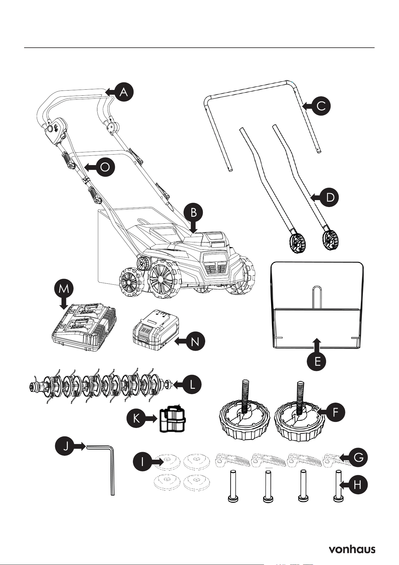
Components
A. Upper Handle
You must hold the handlebar with both
hands during operation.
B. Main Unit
The central operating unit of the machine.
C. Middle Bar
Connects to the lower bars.
D. 2 x Lower Bars
Connect to the main unit.
E. Grass Collector Bag
Collects grass and debris during operation.
F. 2 x Lower Bar Locks
Lock the lower bars into place.
G. 4 x Wing Nuts
Secure the bars together.
Can be loosened to fold the handlebar
down for storage.
H. 4 x Bolts
Secure the bars together.
I. 4 x Bar Washers
Feature indentations to help secure the bolts
and wing nuts together.
J. Hex Key
Tool for assembly and maintenance.
K. Cable Clip
Keeps the cable secure and tight against the
machine.
L. Rake Attachment
Tine attachment may already be installed.
M. Dual Battery Charger
Charges both batteries simultaneously.
N. 2x 20V 4Ah Batteries
Provide power to the machine.
O. Power Cord
Connects the upper handle to the main
body.
Transmits power from the batteries to the
OPC (Operator Presence Control) controls
and then to the motor.
5
Features Fr: Composants / De: Komponenten / Es: Componentes / It: Componenti

6
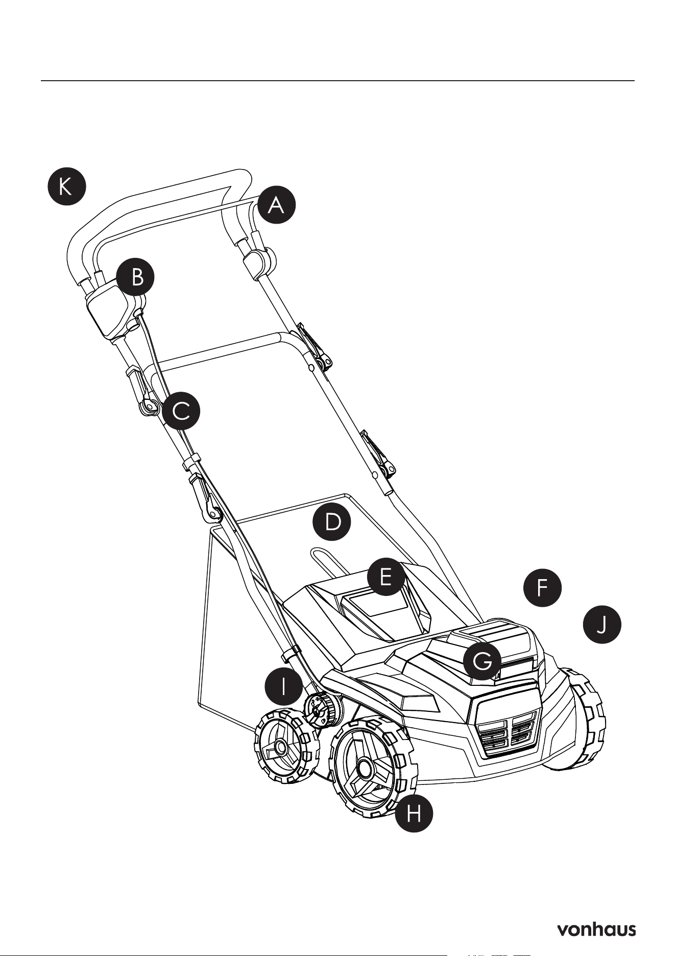
Features
A. Operator Presence Control (OPC)
Handle
Safety feature that stops the machine when the
lever is released.
B. Safety Button
Prevents accidental machine startup.
C. Cable Clip
Keeps the cable secure and tight against the
machine.
Houses the Hex Key.
D. Collection Bag
Collects debris during operation.
E. Rear Discharge Flap
Covers the rear discharge opening.
F. Battery Hatch
Houses the batteries and Safety Key.
G. Main Unit
Central operating component of the machine.
H. Wheels
Enable movement and maneuverability.
I. Lower Bar Lock
Secures the lower bar in position.
J. Depth Adjustment Handle
Allows adjustment of the scarifier’s working
depth.
K. Main Handlebar
Must be held with both hands during opera-
tion.
7
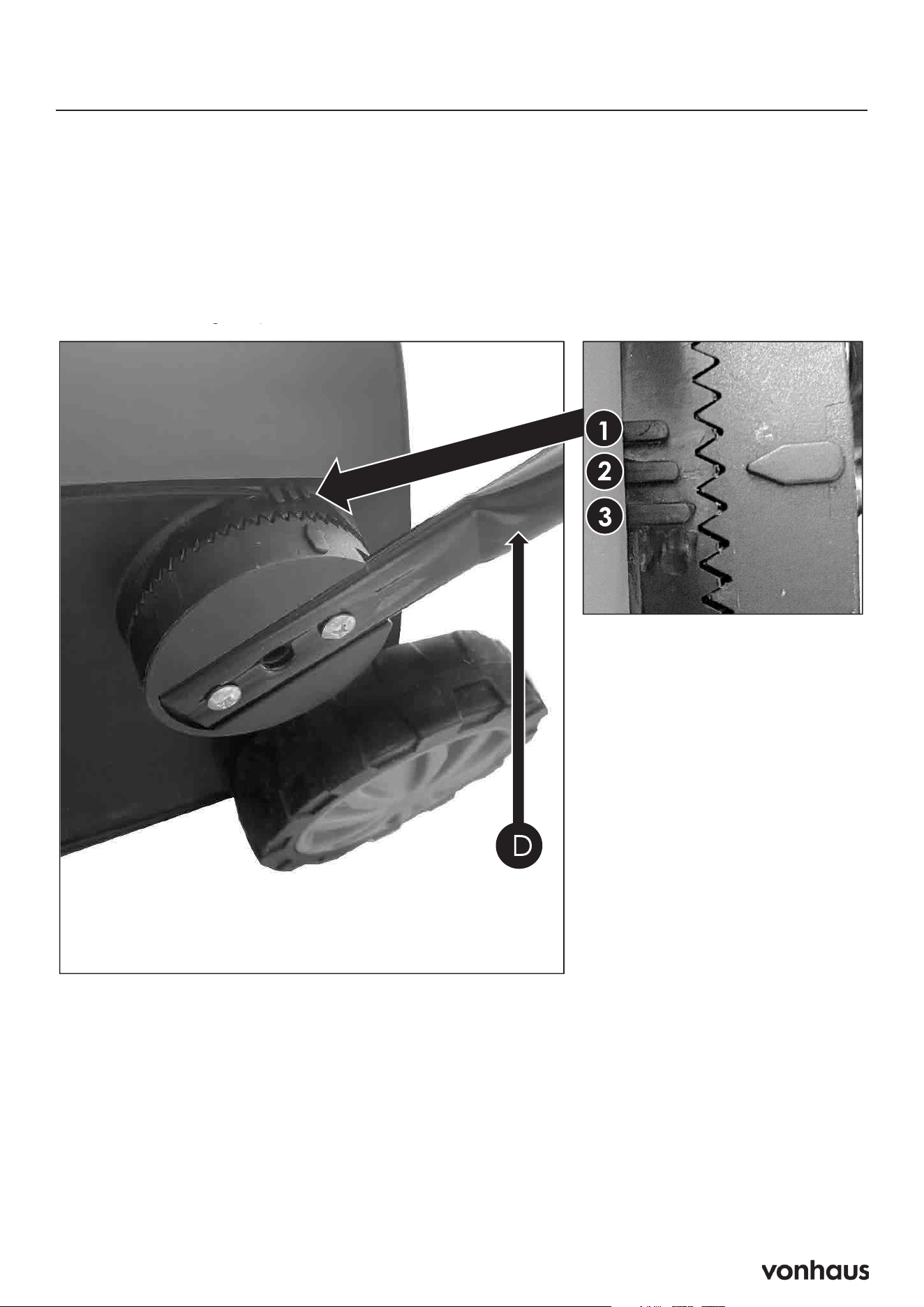
Assembly
Step 1: Attach Lower Handles
1. Slot lower bars (D) into main unit, aligning arrow with your chosen height option:
• Position 1: Shortest height
• Position 2: Standard height
• Position 3: Tallest height
8
Assembly
Step 1 (Continued)
2. Screw in the lower bar lock (F) until it is tight and secure. Turn clockwise to lock
and anti-clockwise to unlock.
20
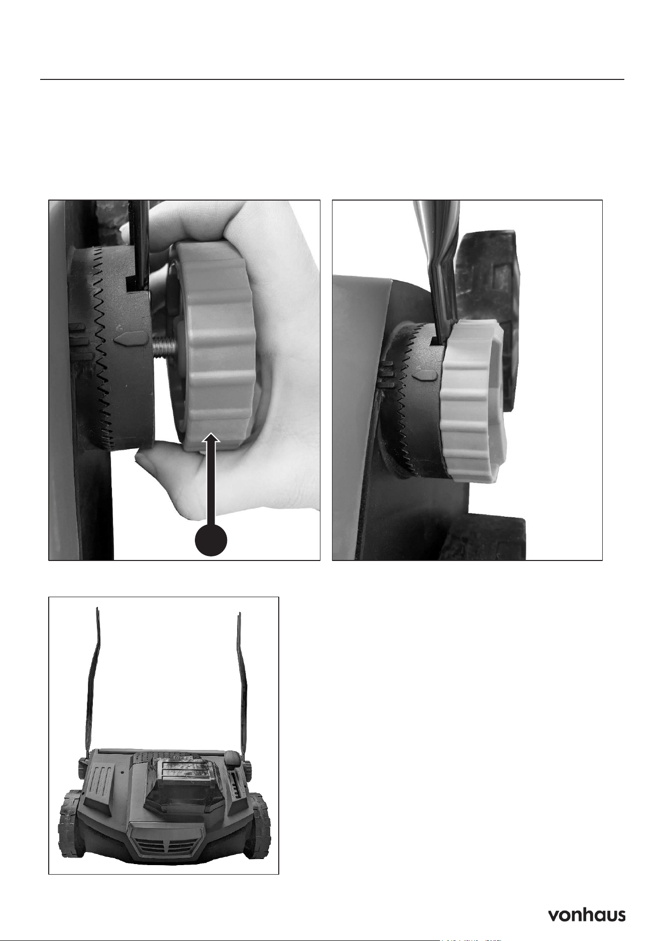
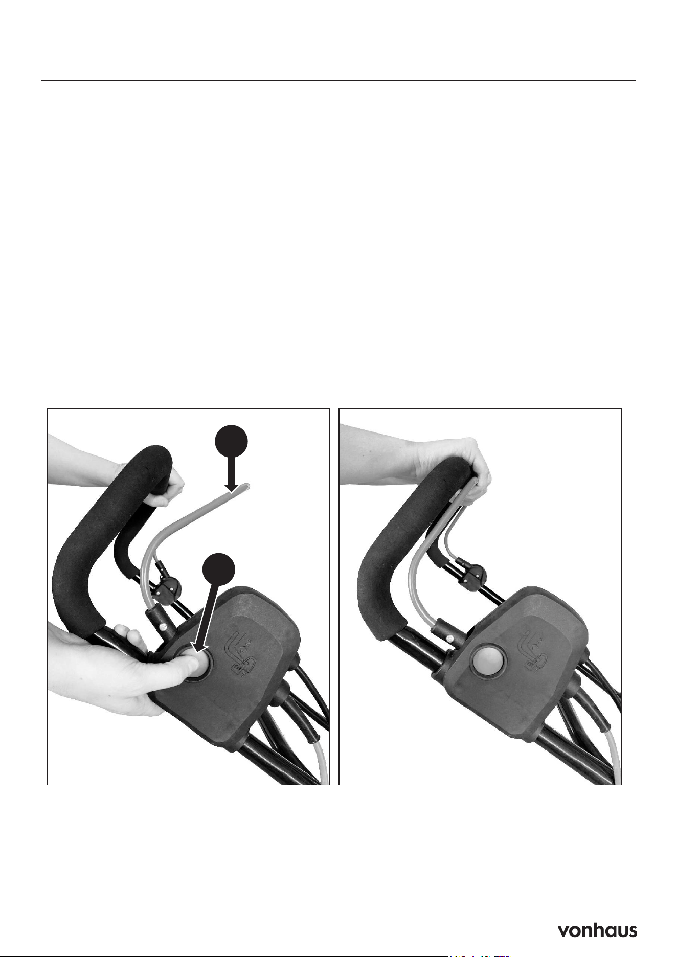
Assembly
STEP 1 : Attach The Lower Handles (Continued)
2. Screw in the lower bar lock (F) until it is tight and secure. Turn clockwise to lock
and anti-clockwise to unlock.
F
3. The scarifier should now look like the image below.
3. It should now look like this.

9
Assembly
Step 2: Attach The Middle Bar
1. Connect the middle bar (C) to the lower bars (D) using the Bolt (H).
2. Place the Bar Washer (I) with the dip facing toward the bars.
3. Twist on the Winged Nut (G) clockwise. When you can press the downward the winged nut is
tightened sufficiently.
4. Repeat on both sides
21
Assembly
STEP 2 : Attach The Middle Bar
1. Connect the middle bar (C) to the lower bars (D) using the Bolt (H).
2. Place the Bar Washer (I) with the dip facing toward the bars.
3. Twist on the Winged Nut (G) clockwise. When you can press the downward the
winged nut is tightened sufficiently.
4. Repeat on both sides
I
H
G
H
C
D
G
H
I
C

10
Assembly
Step 3: Attach The Upper Handle
A. Connect the upper bar (A) to the middle bar (C) using bolts (H). Make sure the upper bar is
attached the correct way as shown in the image.
B. Place the Bar Washer (I) with the dip facing toward the bars.
C. Twist on the Winged Nut (G) clockwise. When you can press the downward the winged nut is
tightened sufficiently.
D. Repeat on both sides
22
Assembly
STEP 3 : Attach The Upper Handle
1. Connect the upper bar (A) to the middle bar (C) using bolts (H). Make sure the
upper bar is attached the correct way as shown in the image.
2. Place the Bar Washer (I) with the dip facing toward the bars.
3. Twist on the Winged Nut (G) clockwise. When you can press the downward the
winged nut is tightened sufficiently.
4. Repeat on both sides
A
C
A
C
H
I
G
11
Assembly
Step 4: Attach Cable Clip
A. Clip the power cord (O) onto the middle bar (C) using the cable clip (K). This will keep the
cable secure and tight to the machine.
B. You can also store the hex key (J) in the cable clip (K) as shown in the image.
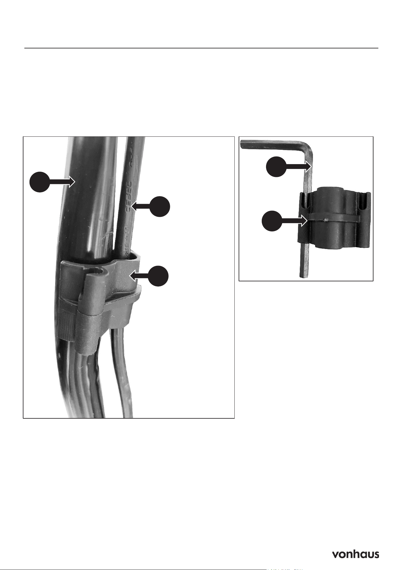
23
Assembly
STEP 4 : Attach Cable Clip
1. Clip the power cord (O)onto the middle bar (C) using the cable clip (K) . This will
keep the cable secure and tight to the machine.
2. You can also store the hex key (J)in the cable clip (K)as shown in the image.
O
C
K
J
K
12
Assembly
Step 5: Assemble Grass Collector
A. Place the metal frame (F1) into the collection bag (F).
B. Attach all fasteners (F2) and make sure they are secure.
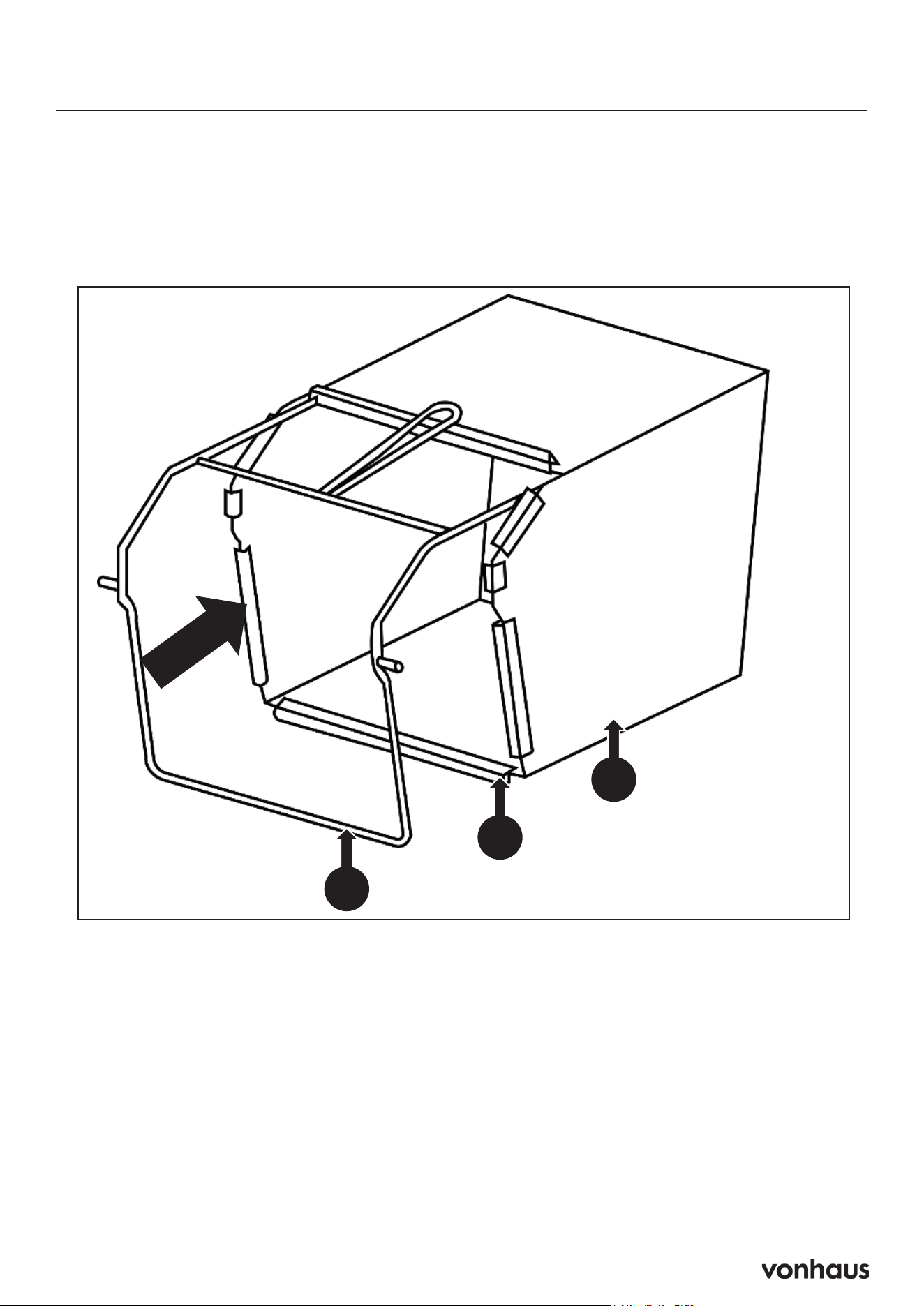
24
Assembly
STEP 5 : Assemble The Grass Collector
1. Place the metal frame (F1) into the collection bag (F). Attach all fasteners (F2)
and make sure they are secure.
F1
F
F2
13
Assembly
Step 6: Attach The Grass Collector
A. Make sure the grass collector is correctly assembled.
B. Lift up the rear discharge flap (1).
C. Make sure that the rear chute is clear and free of debris.
D. Clip the grass collection bag onto the hooks (2).
E. Place the rear discharge flap (1) on top of the collection bag (F) and check that the collection
bag is fitted correctly.
1
2
2
To Remove
A. Lift up the rear discharge flap (1).
B. Lift the grass collector off the hooks (2).
C. Empty the contents of the bag and replace before resuming work.
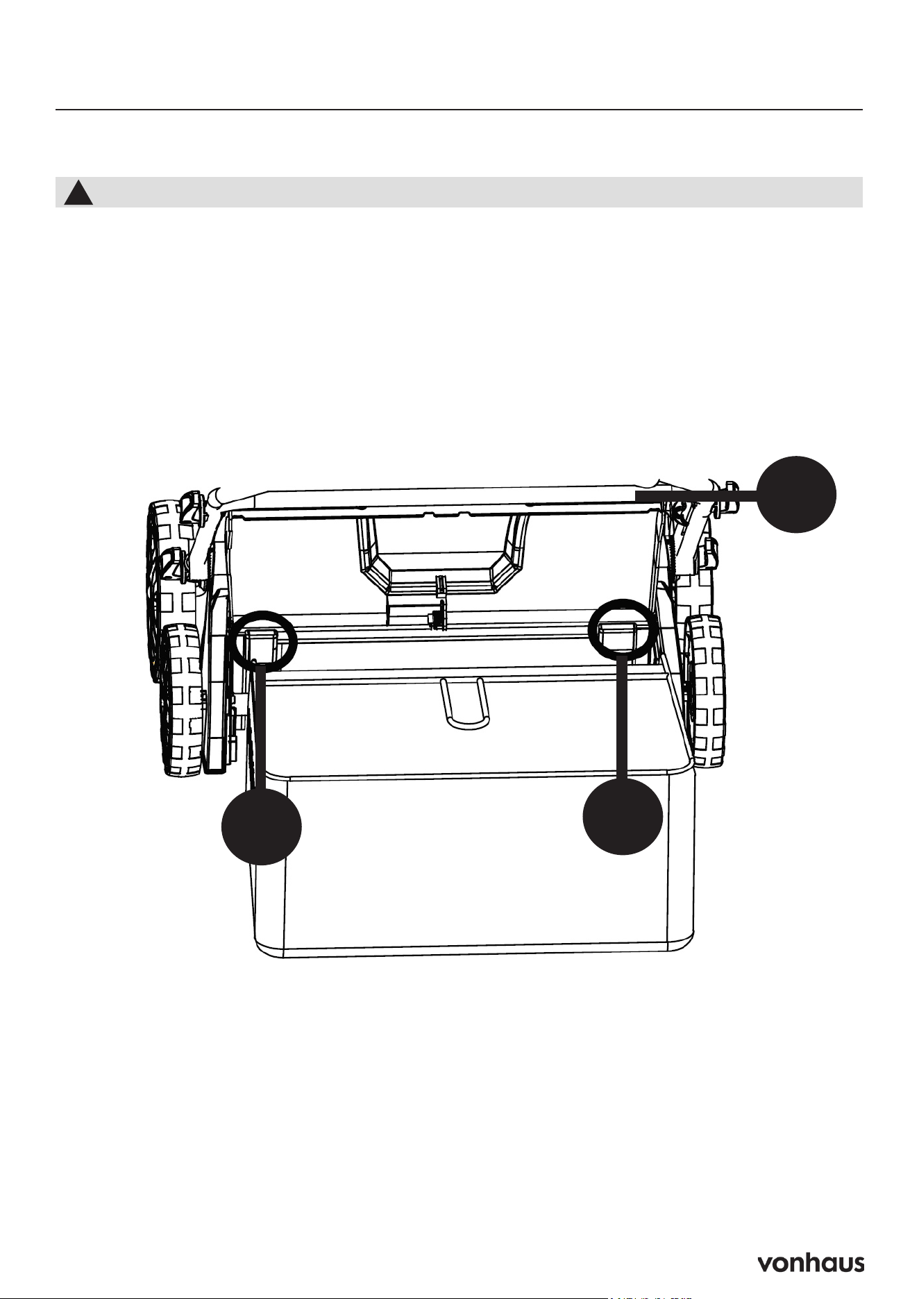
25
Assembly
STEP 6 : Attach The Grass Collector
1. Make sure the grass collector is correctly assembled.
2. Lift up the rear discharge flap (1).
3. Make sure that the rear chute is clear and free of debris.
4. Clip the grass collection bag onto the hooks (2).
5. Place the rear discharge flap (1) on top of the collection bag (F) and check
that the collection bag is fitted correctly.
1
2
2
You must attach the grass collector before use.
!
To Remove
1. Lift up the rear discharge flap (1).
2. Lift the grass collector off the hooks (2).
3. Empty the contents of the bag and replace before resuming work.
14
Assembly
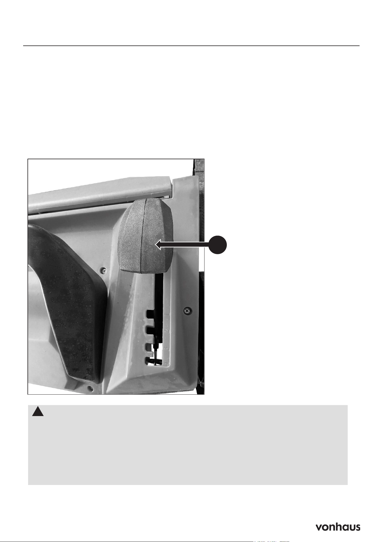
Step 7: Working Depth Adjustment
The working depth is adjustable to 5 heights (+6mm, -3mm, -6mm, -9mm and -12mm).
Be careful not to use the scarifier at too deep a setting. If there is excessive strain on the
motor, it will lose speed and be less efficient.
A. Push the depth adjustment handle (J) forwards or backwards to adjust the height.
26
Assembly
STEP 7 : Working Depth Adjustment
The working depth is adjustable to 5 heights (+6mm, -3mm, -6mm, -9mm and -12mm).
Be careful not to use the scarifier at too deep a setting. If there is excessive strain on the
motor, it will lose speed and be less efficient.
1. Push the depth adjustment handle (J) forwards or backwards to adjust the height.
!
IMPORTANT!
Note: The spring cartridge must only be used in highest three positions.
If you are to use it too deep, the efficiency will be reduced and spring damage
may occur after prolonged use. The springs are made to remove the grass and
moss from the surface. It is not necessary to go deeper into the soil.
The lowest two positions are used for the blade cartridge for heavier moss removal
and scarifying.
J
15
Battery Charger Operation
Important Safety Note
Ensure the power source switch is OFF before
plugging in the Battery Charger.
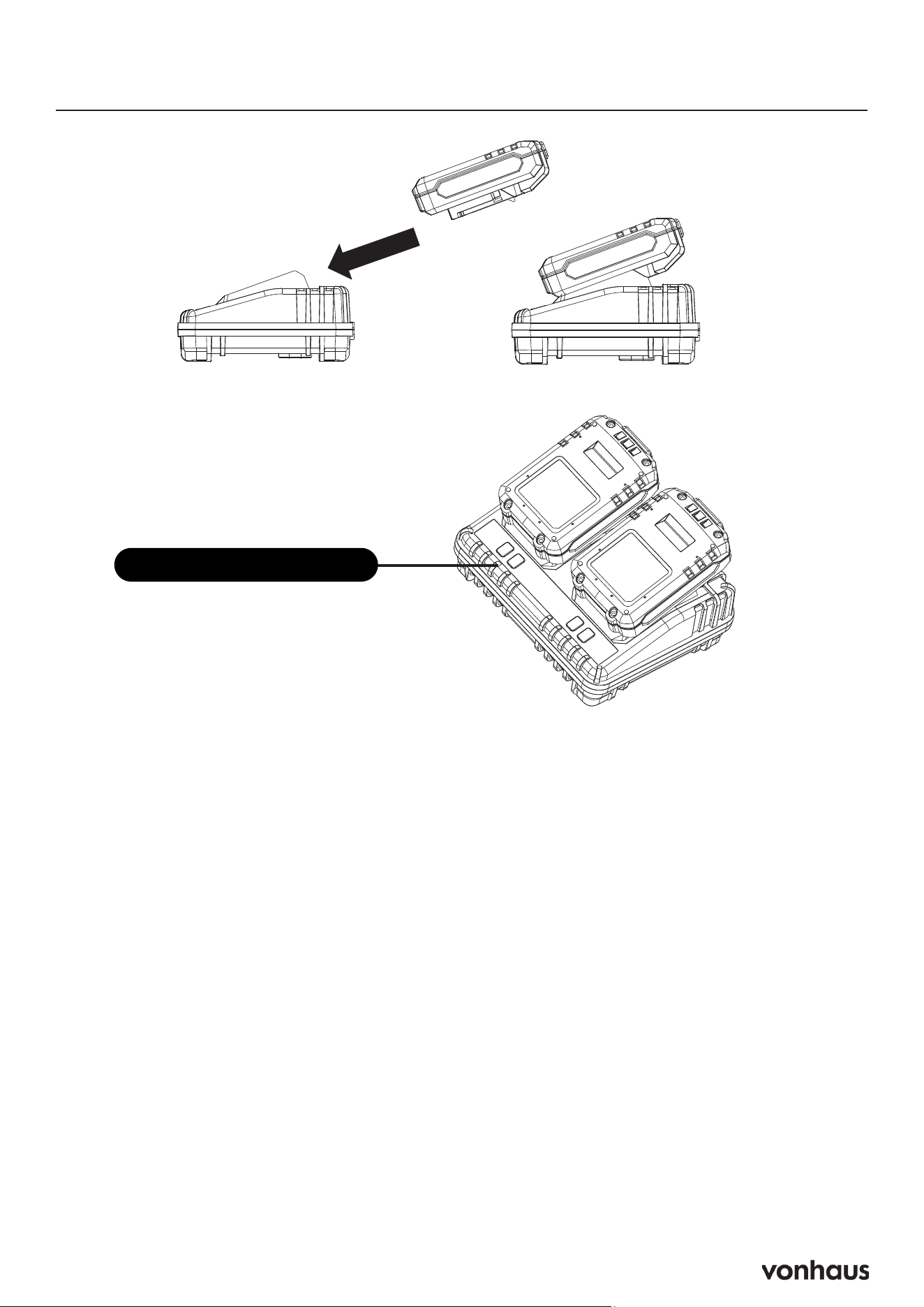
Charging Steps
Insert the Battery
1. Slide the battery into the charger, aligning
the terminals on both the battery and the
charger.
2. The charger lights will illuminate to indicate
that the battery is charging (refer to the
Charge State Light indicators).
Note: To remove the battery, simply pull it
away from the charger.
Power On the Charger
1. Plug in the Battery Charger.
2. Turn on the power source.
Charge State Light Indicators
Solid Green: Ready to charge
Solid Green + Slow Flashing Red: Charging
Solid Green & Solid Red: Fully charged
Slow Flashing Green: Temperature issue
Fast Flashing Red: Defective battery
Battery Charge Indicator
The Battery Charge Indicator uses LED lights
to show the current charge level of the battery.
Here’s what each light means:
4 LEDs Illuminated: Fully Charged
3 LEDs Illuminated: 75% Charged
2 LEDs Illuminated: 50% Charged
1 LEDs Illuminated: Low State of Charge —
Please recharge the battery.
Charge State Indicator
16
Battery Charging & Installation
29
Operation
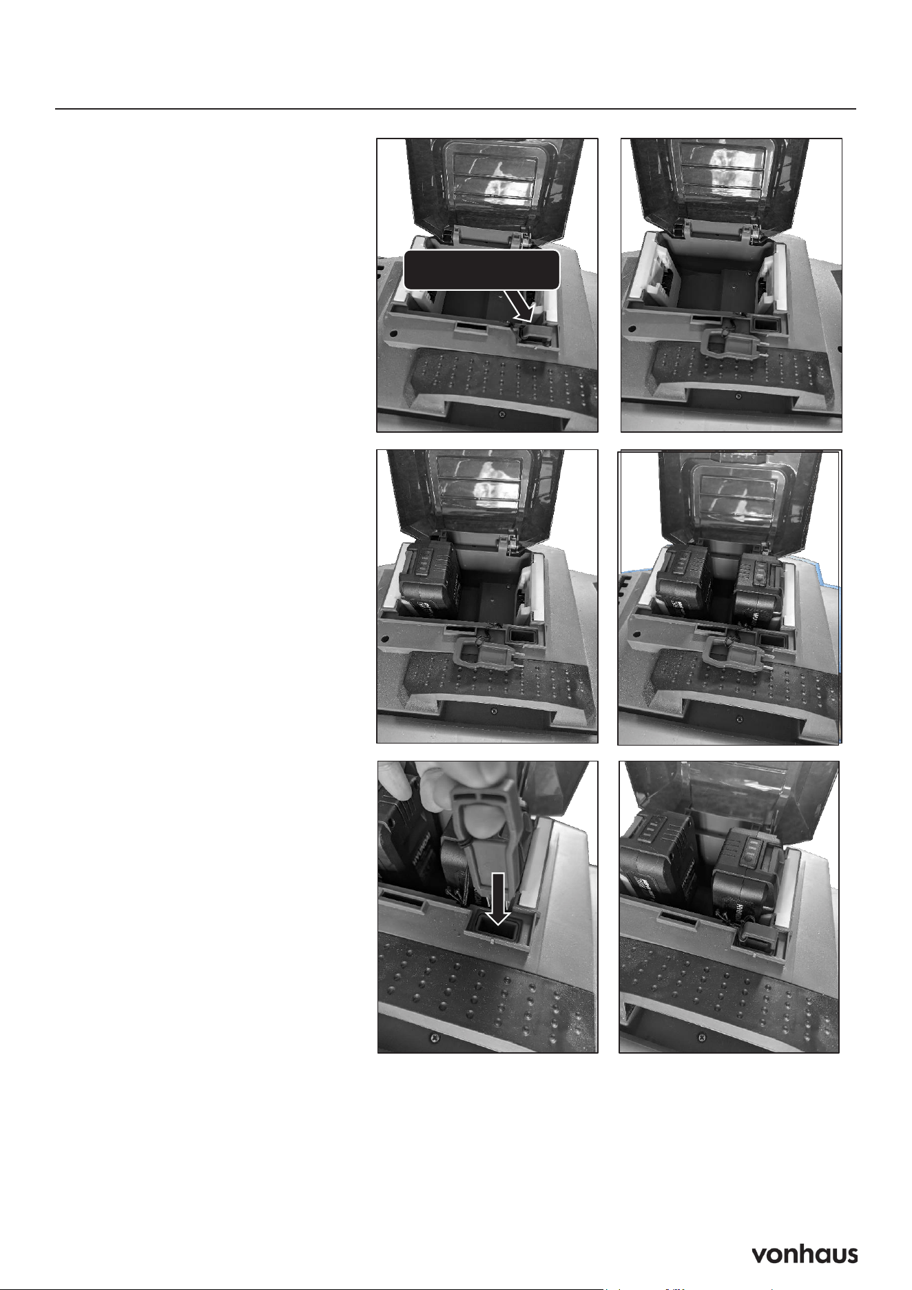
STEP 8 : Battery Charging and Installation
Safety Key
Install Batteries
Reinstall Safety Key
WARNING!
YOU MUST REMOVE THE
SAFETY KEY BEFORE
INSTALLION OR
REMOVAL OF BATTERIES
!
SAFETY KEY
Install the batteries one
at a time. With the
battery terminal facing
the battery cradle
(They can only be
installed 1 way. You will
hear an audible
*CLICK* when installed
correctly.
Install the safety key
back into it’s slot.
Important Safety
Warning
WARNING: You MUST REMOVE
THE SAFETY KEY before installing
or removing batteries!
Battery Installation Steps
Remove the Safety Key
Ensure the safety key is removed
before proceeding.
Install Batteries
Insert the batteries one at a time
with the battery terminals facing the
battery cradle.
Note: Batteries can only be installed
one way. You will hear an audible
CLICK when each battery is in-
stalled correctly.
Reinstall the Safety Key
Once all batteries are installed,
place the safety key back into its
slot.
Follow these steps carefully to en-
sure safe operation.
17
Scarifier and Rake
Using the Scarifier
Benefits of Scarifying: Scarifying removes hardened surfaces, grass felt, and flat-growing
weeds, allowing the lawn to breathe and absorb nutrients, oxygen, and water. This process also
helps prevent bacteria from establishing in the lawn during winter.
Preparation for Scarifying: Cut the grass to a height of about 40 mm before scarifying, and
ensure the lawn is dry. The best time to scarify is during the growing season, from April to Sep-
tember. It’s recommended to scarify at least once a year. For a lush, green lawn, apply fertilizer
immediately after scarifying.
Using the Rake
Benefits of Raking: Raking removes dead matter, moss, and weeds that can disfigure the lawn.
This buildup of dead grass creates a mat that prevents water from penetrating the ground.
Raking Tips: Do not rake grass longer than 50 mm, and ensure the lawn is dry when using the
raker. It’s best to rake at the beginning and end of each grass cutting season, and you can also
do it after each mowing to clear away leftover clippings.
18
Operation
Starting Machine
Safety Checks:
• Inspect the cable for damage; do not use if damaged.
• Ensure no objects or branches are trapped in the machine.
• Keep the work area tidy and free of obstacles.
• Never operate the machine if it is damaged.
Starting Procedure
1. Position the scarifier on the lawn, ensuring it is not sitting on long grass and that the cable is
clear of the cutting blade.
2. Connect the machine to the mains power supply.
3. Press and hold the safety button (B).
4. Pull the OPC lever (A) towards the handle.
5. Release the safety button (B).
33
Operation
Starting
1. Before starting the motor, make sure the scarifier s on the lawn, but not sitting on
long grass. Make sure the cable is well away from the cutting blade.
2. Connect to the mains power supply.
3. Press and hold the safety button (B).
4. Pull the OPC lever (A) to the handle.
5. Release the safety button (B).
!
YOU MUST read and understand the full safety instruction manual before starting
the machine.
Before Starting Work
1. Check the condition of the cable, if damaged do not use.
2. Ensure that no objects or branches are trapped into the machine.
3. Ensure the work area is tidy and free of any obstacles.
4. Never operate the machine if it is damaged in any way.
B
A

19
Operation
Stopping the Machine
Safety Checks:
1. Stopping the Machine
2. Release the OPC Lever (A).
3. Unplug from the Mains Supply.
• WARNING: Always turn off the ma-
chine before setting it down.
• The cutting elements may continue to rotate
briefly after the motor is switched off. Do
not touch the underside of the machine until
the cutters have completely stopped.
!
34
Operation
WARNING : Cutting elements continue to rotate for a moment after the motor is
switched off. Do not touch the underside of the machine until the cutter has come
to a standstill.
!
WARNING : Always switch off machine before placing it down.
Stopping
1. Release the OPC lever (A).
2. Unplug from the mains supply.
A
20
Replacing the Blade
WARNING! Always wear protective gloves when working with the blade.
•Check the blade. The blade should always be sharp. At regular intervals, check the tightness of
all nuts, bolts and screws.
•If the blade hits an obstacle, check for damage and if the machine vibrates badly,
Replacing the Blade
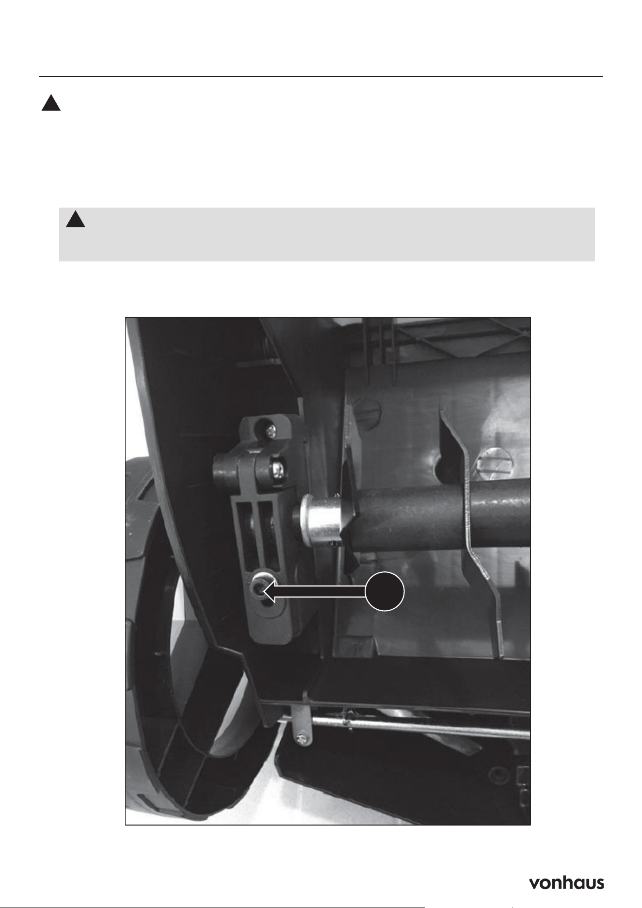
1. Remove the Bolt: Unscrew bolt (T) located on the underside of the chassis.
36
Maintenance & Care
Replacing Blades
The cylinders may cause injuries. Prior to replacement, disconnect the machine
from the power supply and wait for the blades to stop completely. You must always
wear gloves to protect your hands.
!
1. Screw out bolt (T) on the underside of the chassis.
The Blade
WARNING! Always wear protective gloves when working with the blade.
• Check the blade. The blade should always be sharp. At regular intervals, check
the tightness of all nuts, bolts and screws.
• If the blade hits an obstacle, check for damage and if the machine vibrates
badly, stop the machine and take it to a service dealer.
!
T
21
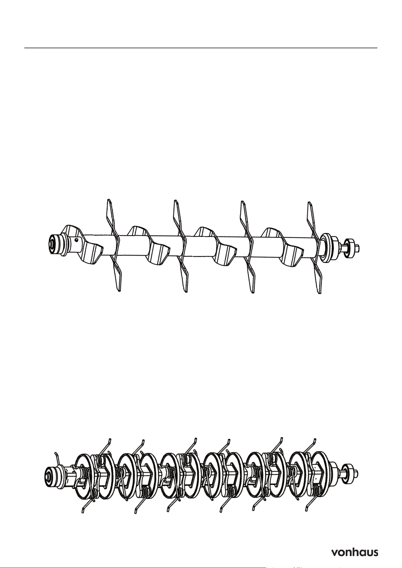
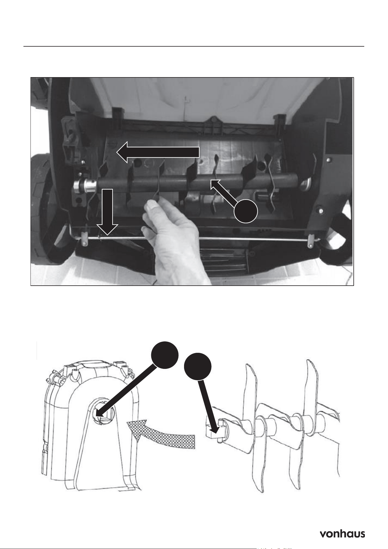
Replacing the Blade
2. Lift the Cylinder: At an angle, lift the cylinder (U) and pull it out.
37
Maintenance & Care
Replacing Blades (Continued)
2. Lift the cylinder (U) at an angle and pull it out.
U
W
V
3. Slide the second cylinder onto the drive shaft so that the pin (V) fits into the
respective part of the drive shaft (W).
4. Tighten the screw (T) to secure again.
37
Maintenance & Care
Replacing Blades (Continued)
2. Lift the cylinder (U) at an angle and pull it out.
U
W
V
3. Slide the second cylinder onto the drive shaft so that the pin (V) fits into the
respective part of the drive shaft (W).
4. Tighten the screw (T) to secure again.
3. Install the New Cylinder: Slide the new cylinder onto the drive shaft, ensuring that the pin
(V) fits into the corresponding part of the drive shaft (W).
4. Secure the Cylinder: Tighten screw (T) to secure the cylinder in place.

22
Troubleshooting
PROBLEM POSSIBLE CAUSE SOLUTION
Tines will not ro-
tate
Tines are clogged by dirt and
debris
Remove the battery packs and start
key, then remove any obstruction from
the tines
Vines, grass or other debris
wrapped around tine shaft
Remove the battery packs and start
key, then clean the tine shaft
Motor fails to
start when bail is
pulled
Battery is low in charge Charge the battery
Batteries not in correct orienta-
tion (minimum of one pair)
Confirm battery orientation
Start key arrow not pointing
to a charged pair of battery
packs
Reverse the position of the start key
Start button is not de-
pressed
Press start button and pull the bail
The motor is on but
the tines do not
turn
Start button is not depressed
or transport mode is activat-
ed
Press the start button and pull the bail
with the speed control lever 3/4 for-
ward
The tines stop rotat-
ing
The unit is overloaded Release the bail and raise the tines.
Restart the tiller and tines, then slowly
lower the tines back to their original
depth
38
Maintenance & Care
Troubleshooting
NOTE : All corrective actions should be carried out by suitably qualified
person/s.
!
PROBLEM POSSIBLE CAUSE SOLUTION
Tines will not rotate Tines are clog ged by dirt
anddebris.
Vines, grass or other
debriswrapped around
tine shaft.
Remove the battery packs and start key, then
removeany obstruction from the tines.
Remove the battery packs and start key, then
cleanthe tine shaft.
Motor fails to start when bail
ispulled
Battery is low in ch arge.
Batteries not in correct
orienta-tion (minimum of one
pair).
Start key arrow not p ointing
toa charged pair of batte
ry
packs
Start button is not depressed.
Charge the battery.
Confirm battery
orientation.
Reverse the position of the start key.
Press start button and pull the bail.
The motor is on but the tines
do
not turn.
Start butt on is not depressed
ortransport mode is activated
Press t he start button and pull the bail with the
speedcontrol lever 3/4 forward.
The tin es stop rotating The unit is overloaded. Release the bail and raise the tines. Restart the
tillerand tines, then slowly low er the tines back
to their original dept
h.

23
Personal Protective Equipment
12
Safety Information
Personal Protective Equipment
Appropriate Personal Protective Equipment (PPE), MUST be worn at all times when
operating or repairing the machine. No protective equipment can ensure 100%
protection.
When selecting PPE, make sure it’s CE marked and it suits the user in terms of size,
fit, etc. If more than one item of PPE is worn at the same time, make sure they can
be used together, e.g. wearing safety glasses may disturb the seal of a respirator,
causing air leaks.
!
Hand Protection Must Be Worn
Protective electrically non-conductive gloves are highly
recommended when working.
Foot Protection Must Be Worn
Non-skid heavy duty footwear are highly recommended when
working.
Hearing Protection Must Be Worn
Suitable safety hearing protection is recommended.
Eye Protection Must Be Worn
Always wear safety glasses/goggles and/or face shields. Everyday
eyeglasses have only impact resistant lenses; they are not safety
glasses/goggles.
Protective Clothing Must Be Worn
Do not wear loose clothing, gloves, scarfs, neckties or jewellery (rings,
wrist watches), which can be caught in moving parts.
Head Protection Must Be Worn
Wear a safety helmet with a safety visor.
Face Shield Must Be Worn
Wear a face shield to protect your face.

24
Symbols on Machine
13
Safety Information
Symbols On The Machine
We have provided safety messages in this manual and on the machine. This
information alerts you to potential hazards that could hurt you or others. Please
read these messages carefully. However, we may not have listed all of the possible
hazards, you must also use your own judgement.
!
Symbol Description Symbol Description
Safety alert – Indicates a
precaution, a warning or a
danger.
Wear eye and hearing
protection. For protection
against injury, wear ear
defenders and safety
goggles.
Do not expose to rain.
Read operator’s manual.
Keep bystanders at a safe
distance away from the
work area.
This product complies with
the European directives and
an evaluation method of
conformity for these
directives was done.
Sharp blades can cut limbs
Danger! Rotating blades –
keep hands and feet away
from moving parts.
Switch off and unplug the
device before cleaning or
performing maintenance
on it.
Keep bystanders at a safe
distance away from the
work area.
This product should not be
disposed of in domestic
waste. Please contact your
local recycling centre for
disposal service.

25
Safety
Key Points
A. Read and understand all instructions be-
fore use
B. Know how to stop the machine quickly
C. Only allow trained adults to operate the
machine
D. Save manual for future reference
Operation Safety
Maintain 15m safety zone from others
Stay alert and focused while operating
Never operate when tired or under influence
Don’t exceed machine’s limits
Stop if anyone enters work area
Required Safety Gear
Anti-slip work boots
Long trousers
Ear protection
Safety goggles with side shields
No loose clothing/jewelry
Tie back long hair
Critical Safety Rules
Keep hands/feet away from moving parts
No children or untrained operators
Professional maintenance required except as
listed
First-time users need training from experi-
enced operator
Operator is responsible for accidents/injuries
Before Each Use
Check all nuts and bolts are tight
Inspect general condition
Verify all guards are in place
Remove any tools/keys from machine
Check for worn/damaged parts
Ensure safety devices work
Verify warning labels are visible
Operation Rules
Allow hot parts to cool before touching
Maintain proper footing and balance
Don’t overreach
Watch for abnormal vibration
Ensure power switch works properly
Only use manufacturer-approved attach-
ments
Operator Responsibilities
Assess work area risks
Take extra care on slopes/unstable ground
Prevent accidental starts
Don’t disable safety features
Keep machine well-maintained
Stop use if repairs needed
Report/address any issues immediately
Key Safety Points
Keep body away from danger zones
Operator is responsible for accidents
Maintain machine in good condition
Replace damaged parts promptly
Stop if abnormal vibration occurs

26
Safety
Acceptable Working Conditions
• Daylight or good artificial light only
• Dry ground
• Flat, level surfaces
• Outdoor use only
• Clear visibility
Never Operate During
• Night time
• Heavy fog
• Rain or thunderstorms
• Strong winds
• Wet ground conditions
• Poor visibility
Work Area Preparation
Inspect entire area thoroughly
Remove hazards:
• Branches
• Stones
• Wire
• Toys
• Any loose objects
Locate and mark fixed objects:
• Sprinkler systems
• Poles
• Water valves
• Washing line bases
• Hidden cables
Prohibited Conditions
Near unstable ground
Close to ravines/ditches
In explosive atmospheres
Near flammable materials
On wet/slippery surfaces
When visibility is limited
Remember
Keep 15m safety zone from others
Never run machine over foreign objects
Always go around fixed objects
Clean area before starting work
When to Switch Off
Before any inspections
During transport
Leaving machine unattended
Abnormal vibration occurs
Hitting foreign object
Any accident/incident
Before adjustments
Emergency Procedures
Turn off machine immediately
Move machine from area
Provide first aid if needed
Contact medical help if required
Clear any dangerous debris
Inspect for damage
Repair before restarting
Never
Operate in confined spaces
Make adjustments while running
Use without guards
Keep hands/feet near cutting parts
Continue after striking objects without inspec-
tion
Use damaged equipment

27
Safety
Battery Safety Protocol
Battery Hazards
• Damaged batteries may leak electrolyte
(acid)
• Can cause severe burns
• Produces flammable gases when charging
• Risk of explosion from short circuits
• If Electrolyte Contact Occurs:
Immediate Actions:
Remove contaminated clothing
Saturate clothing in water if stuck
Use running water on affected areas
Avoid spreading to other body parts
Medical Response:
Seek immediate medical help
Specify battery type:
Lead/acid = dilute sulphuric acid
Nickel/cadmium = potassium hydroxide
Eye Contact:
• Flush immediately with lots of water
• Keep flushing until medical help arrives
• Avoid spreading to other areas
Safety Precautions
• Charge in well-ventilated areas
• Use insulated tools only
• Prevent terminal short circuits
• Exercise care when connecting/discon-
necting
• Avoid sparks
Electrical Safety Protocol
CRITICAL WARNING
ELECTRICITY CAN KILL - NEVER WORK
ON LIVE EQUIPMENT
⚡
Required Pre-Use Checks
• Isolate all electrical supplies
• Inspect cables, plugs, connectors for:
• Bare wires
• Chaffing
• Cuts
• Loose connections
• Any damage
Safety Rules
• Keep all equipment dry
• Never use with wet hands/clothing
• Route cables to prevent trips
• Ensure proper circuit fusing
• Verify correct voltage/frequency
• Maintain proper grounding
• Avoid earthed surface contact
When Damage Found
Remove from service immediately
Mark as damaged
Have repairs done by qualified electrician
Never attempt DIY repairs
Double-Insulated Equipment
• This machine has two insulation systems
• No additional grounding needed
• Requires specialized service
• Use identical replacement parts
• Service by qualified personnel only
Remember
• Never contact water during operation
• Keep power components dry
• Use rubber boots for protection
• Never open switch box yourself
• Contact qualified electrician for repairs

28
Safety
Vibration Risks
• Can cause white finger disease (Ray-
naud’s)
• May lead to carpal tunnel syndrome
• Can damage nerves and circulation
Prevention:
• Wear warm gloves
• Take regular breaks
• Monitor hand/finger condition
• Seek medical help if symptoms appear
Noise Hazards
• Can cause hearing damage
• Reduces ability to hear warnings
• Requires scheduled work periods
• Use in approved time windows only
Protection Required:
• Wear ear defenders/plugs
• Regular hearing checks
• Be extra alert when wearing protection
Residual Risks
• Lung damage without dust mask
• Hearing damage without protection
• Vibration-related health issues
• Electromagnetic field interference with
medical implants
Proper Use Guidelines
• For grass/moss removal only
• Single operator use
• Domestic/DIY use only
• Pedestrian-controlled operation
Never Use For:
• Non-grass surfaces
• Carrying passengers
• Towing loads
• Debris collection
• Multiple operators
Important
• Consult doctor if using medical implants
• Follow all safety protocols
• Maintain machine properly
• Use appropriate protective gear

29
Technical Data
39
Technical Data
Specification
Model
Motor Type 2 x 20V Brushless
Working Width 38cm
Working Depth +6mm to -12mm
Grass Collector Capacity 45L
Protection Class IPX4
Cylinder Operating Speed 3000rpm
Sound Pressure Level Lpa = 78.1dB(A)
K=3dB(A)
Guaranteed Sound Power Level Lwa = 93dB(A)
Vibrations
2.222m/s
2
K= 1.5m/s
2
Net Weight 10.6kg

30
Thank You
Thank you for purchasing your product/appli-
ance.
Should you require assistance with your pur-
chase, please contact us at support@domu.
co.uk
VonHaus is a registered trademark of DOMU
Brands Ltd. Made in China for DOMU Brands.
VonHaus is a registered trademark of DOMU
Brands Ltd.
Made in China for DOMU Brands.
Authorised Representative
Authorised Representative Service
77 Camden Street Lower
Dublin, D02 XE80, Ireland
Information

31
Legal
DISPOSAL INFORMATION
Please recycle where facilities exist. Check with
your local authority for recycling advice.
CUSTOMER SERVICE
If you are having difficulty using this product
and require support, please contact support@
vonhaus.com
WARRANTY
To register your product and find out if you
qualify for a free extended warranty please go
to www.vonhaus.com/warranty.
Please retain a proof of purchase receipt or
statement as proof of the purchase date.
The warranty only applies if the product is used
solely in the manner indicated in the warnings
page of this manual, and all other instructions
have been followed accurately.
Any abuse of the product or the manner in which
it is used will invalidate the warranty.
RETURNS
Returned goods will not be accepted unless
re-packaged in its original packaging and ac-
companied by a relevant and completed returns
form. This does not affect your statutory rights.
No rights are given under this warranty to a
person acquiring the appliance second-hand
or for commercial or communal use.
COPYRIGHT
All material in this instruction manual are copy-
righted by DOMU Brands.
Any unauthorised use may violate worldwide
copyright, trademark, and other laws.

Product No. 3519009