BG-IPGEAR-ULTRA
(BG-IPGEAR-ULTRA-C & BG-IPGEAR-ULTRA Transceiver)
4K UHD HDMI 2.0 Over IP Multicast Transceiver with Seamless
Matrix Switching/Video Wall/MultiView/KVM/USB 2.0/POE Support
User Manual

BZBGEAR BG-IPGEAR-ULTRA PRODUCT MANUAL
Address: 830 National Drive #140, Sacramento, CA 95834, USA · Tel: +1(888)499-9906 · Email: support@bzbgear.com 2

BZBGEAR BG-IPGEAR-ULTRA PRODUCT MANUAL
TABLE OF CONTENTS
Statement 4
Safety Precaution 4
Introduction 5
Features (BG-IPGEAR-ULTRA-C) 6
Features (BG-IPGEAR-ULTRA Transceiver) 6
Packing List (BG-IPGEAR-ULTRA-C) 7
Packing List (BG-IPGEAR-ULTRA Transceiver) 7
Specifications (BG-IPGEAR-ULTRA-C) 8
Specifications (BG-IPGEAR-ULTRA Transceiver) 9
Operation Controls and Functions 10
IR Pin Definition (BG-IPGEAR-ULTRA-C) 14
Web GUI Setup (BG-IPGEAR-ULTRA-C) 15
Web GUI Functions and Operations (BG-IPGEAR-ULTRA-C) 16
Device Page 16
Matrix Page 24
Video Wall Page 24
Controller Settings 28
Firmware Update Page 30
User Page 31
Password Page 33
Connection Diagram 34
FAQ 35
Troubleshooting 37
Tech Support 38
Limited Product Warranty Terms 38
Mission Statement 38
Copyright 38
Address: 830 National Drive #140, Sacramento, CA 95834, USA · Tel: +1(888)499-9906 · Email: support@bzbgear.com 3

BZBGEAR BG-IPGEAR-ULTRA PRODUCT MANUAL
Statement
Please read these instructions carefully before connecting, operating, or configuring this
product. Please save this manual for future reference.
Safety Precaution
● To prevent damaging this product, avoid heavy pressure, strong vibration, or immersion
during transportation, storage, and installation.
● The housing of this product is made of organic materials. Do not expose to any liquid,
gas, or solids which may corrode the shell.
● Do not expose the product to rain or moisture.
● To prevent the risk of electric shock, do not open the case. Installation and maintenance
should only be carried out by qualified technicians.
● Do not use the product beyond the specified temperature, humidity, or power supply
specifications.
● This product does not contain parts that can be maintained or repaired by users.
Damage caused by dismantling the product without authorization from BZBGEAR is not
covered under the warranty policy.
● Installation and use of this product must strictly comply with local electrical safety
standards.
Address: 830 National Drive #140, Sacramento, CA 95834, USA · Tel: +1(888)499-9906 · Email: support@bzbgear.com 4

BZBGEAR BG-IPGEAR-ULTRA PRODUCT MANUAL
Introduction
The BG-IPGEAR-ULTRA-C delivers advanced management for the BG-IPGEAR-ULTRA
AVoIP system with robust processing powered by a state-of-the-art CPU. It features dual
1G network ports, enabling full isolation between control and video networks, with PoE
support on the VIDEO LAN port. The controller supports AES256 video encryption,
HTTPS/SSH security, and provides flexible control interfaces including Web GUI, TCP/IP,
RS-232, IR, and GPIO.
Designed for demanding AV applications, it enables video wall processing with window
roaming and marquee, seamless switching, IP camera integration, and high-definition
background support for both video and images. Key capabilities include audio, video,
RS-232, and KVM management, dual RS-232 ports for external device control, IR signal
loop output, and GPIO ports for automation, making it a versatile and reliable solution for
professional AV deployments.
The BG-IPGEAR-ULTRA AV-over-IP transceiver is capable of functioning as both an
encoder and decoder, making it ideal for flexible system designs. It features HDMI input and
output ports, allowing seamless integration with source and display devices, while an SFP
slot and LAN port with PoE support provide robust connectivity options over copper or fiber
networks. Additional interfaces include a balanced audio terminal block, RS-232, IR
(TX/RX), and GPIO, enabling full integration with third-party control systems and external
devices.
Designed for professional AV environments, the unit supports USB 2.0 and USB Host ports
for KVM extension, allowing remote workstation control in distributed setups. The front
panel includes status LEDs for encoder/decoder mode, network activity, speed, and system
health, along with a convenient power button for local operation. With its comprehensive
connectivity, control options, and reliable PoE-powered design, the BG-IPGEAR-ULTRA
transceiver delivers the scalability and performance required for applications such as video
walls, digital signage, command centers, and enterprise AV distribution.
Address: 830 National Drive #140, Sacramento, CA 95834, USA · Tel: +1(888)499-9906 · Email: support@bzbgear.com 5

BZBGEAR BG-IPGEAR-ULTRA PRODUCT MANUAL
Features (BG-IPGEAR-ULTRA-C)
● High-Performance CPU: ARM Cortex-A55 2GHz processor
● Secure Connectivity: HTTPS and SSH compatibility
● Advanced Security: AES-256 video encryption support
● Web-Based Control: Built-in GUI for quick setup and management
● Intuitive Operation: Drag-and-drop source selection with live video preview
● Video Wall Support: Window roaming, marquee, and flexible layouts
● Seamless Switching: Smooth transitions across the distributed system
● KVM Collaboration: Mouse roaming for managing multiple PCs with one operator
● Comprehensive Control: Video, audio, RS-232, and KVM system management
● Dual Network Ports: Isolated control and video networks (VIDEO LAN supports
PoE)
● IP Camera Integration: Import IP cameras as sources
● Custom Display Options: High-definition background images and multi-screen
splicing
● RS-232 Control: Dual ports for central control or external device connection
● IR Signal Support: Receiving and loop output via 3.5mm audio jack (12V level)
● GPIO Control: Four channels (5V/12V optional) for external devices
● 3rd Party Integration: Compatible with major control system brands
● Robust Protection: Multi-circuit, lightning, and ESD protection
● Flexible Power: PoE (802.3af PD) or 12V local power supply
● Rack Compatibility: Fits 1U/6U V2 rack installations)
Features (BG-IPGEAR-ULTRA Transceiver)
● Dual Operation: Functions as both an encoder and decoder for flexible AV-over-IP
deployments
● Versatile Connectivity: HDMI input/output, SFP slot, and LAN port with support for
both fiber and copper transmission
● PoE Powering: Standard PoE (802.3af Class 3, PD mode) for simplified installation
or local power option
● Comprehensive Control: Supports video, audio, RS-232, IR, GPIO, and KVM
system management across distributed networks
● KVM Extension & Management: USB 2.0/Host ports enable remote workstation
control and centralized seat management
● Video Wall Functions: Window roaming, screen preview, and flexible layout options
for multi-display environments
● Content Overlay: Supports scrolling subtitles, character overlay, and OLED bar
screen functions
● Integrated Control System: Built-in central control with mobile app support for
touch-based operation
● User Access Control: Hierarchical management of permissions for secure and
personalized account access
Address: 830 National Drive #140, Sacramento, CA 95834, USA · Tel: +1(888)499-9906 · Email: support@bzbgear.com 6

BZBGEAR BG-IPGEAR-ULTRA PRODUCT MANUAL
● Front Panel Status: LEDs for encoder/decoder mode, network activity, link speed,
and system health plus local power button
● Visual Interaction Mode: Source selection, screen status, scene preview, and
environment visualization in one interface
● Professional Audio: Balanced audio terminal block for integration with pro AV
systems
● Third-Party Integration: Compatible with major control platforms via RS-232, IR,
and GPIO
● Reliable Protection: Multi-circuit design with lightning, ESD, and surge protection
Packing List (BG-IPGEAR-ULTRA-C)
● 1x H.264/265 Video over IP Controller
● 1x 20kHz-60kHz 12V IR Receiver Cable (1.5 meters)
● 1x IR Blaster Cable (1.5 meters)
● 2x 3-pin 3.81mm Phoenix Connector (Male)
● 1x 6-pin 3.81mm Phoenix Connector (Male)
● 2x Mounting Ear
● 4x Machine Screw (KM3*6)
● 1x 12V/2.5A Locking Power Adaptor
● 1x User Manual
Packing List (BG-IPGEAR-ULTRA Transceiver)
● 1 x H.264/H.265 4K60 AV over IP Transceiver
● 2 x 6pin-3.81mm Phoenix Connector (male)
● 1 x 3pin-3.81mm Phoenix Connector (male)
● 1 x 12V 2.5A Locking Power Supply
● 2 x Mounting Ear
● 4 x Machine Screw (M3*4)
● 1 x User Manual
Address: 830 National Drive #140, Sacramento, CA 95834, USA · Tel: +1(888)499-9906 · Email: support@bzbgear.com 7
BZBGEAR BG-IPGEAR-ULTRA PRODUCT MANUAL
Specifications (BG-IPGEAR-ULTRA-C)
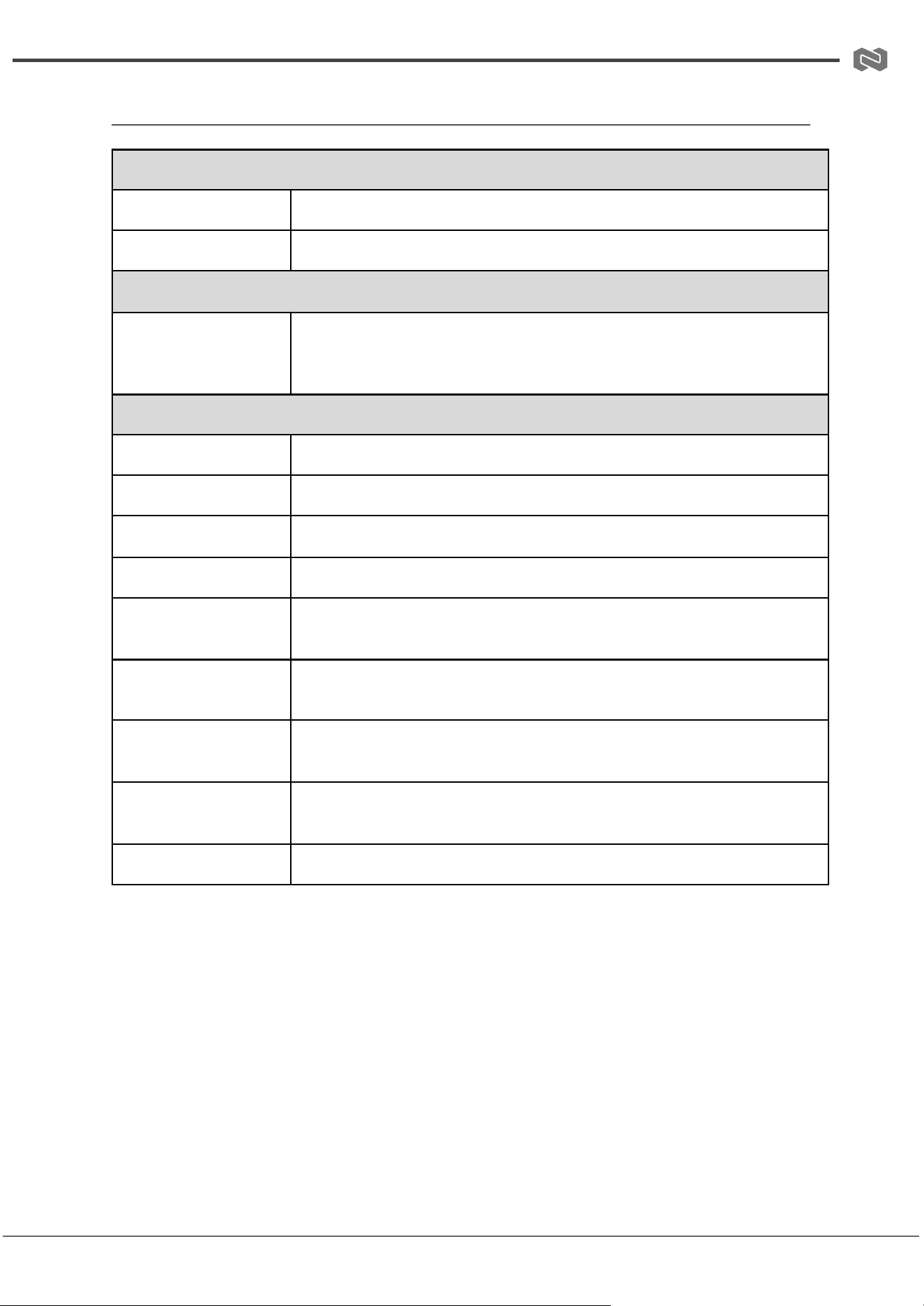
Technical Specifications
Network
Bandwidth
1G
Transmission
Distance
100m (CAT5E/6/6A/7)
Control Ports
2 x 1G LAN [RJ45 connector] [VIDEO LAN supports PoE]
1 x IR IN [3.5mm audio jack, 12V level]
1 x IR OUT [3.5mm audio jack, 5V level]
1 x DIGITAL I/O [6-pin 3.81mm phoenix connector]
2 x RS-232 [3-pin 3.81mm phoenix connector]
1 x UPDATE [Micro USB, 5-pin female]
Mechanical Specifications
Dimensions
204mm (W) × 117.5mm (D) × 21.5mm (H)
Housing
Metal Enclosure
Color
Black
Weight
597g
Power Supply
12V/2.5A
Power
Consumption
6.84W
Operating
Temperature
0°C ~ 40°C / 32°F ~ 104°F
Storage
Temperature
-20°C ~ 60°C / -4°F ~ 140°F
Operating
Humidity
20% ~ 80% RH (relative humidity, non-condensing)
Storage
Humidity
10% ~ 90% RH (relative humidity, non-condensing)
Address: 830 National Drive #140, Sacramento, CA 95834, USA · Tel: +1(888)499-9906 · Email: support@bzbgear.com 8
BZBGEAR BG-IPGEAR-ULTRA PRODUCT MANUAL
Specifications (BG-IPGEAR-ULTRA Transceiver)
Technical Specifications
Network Port
1000M Base-T (supporting POE)
ESD Protection
IEC 61000-4-2: ±8kV (Air-gap discharge), ±4kV (Contact discharge)
Connection Specifications
Control
1 × LAN (POE) [RJ45, supporting POE]
1 × RS-232 [3-pin phoenix connector]
1 × SFP [Fiber slot]
Mechanical Specifications
Housing
Metal Enclosure
Color
Black
Dimensions
204mm [W] × 132mm [D] × 30mm [H]
Weight
760g
Power Supply
Input: AC 100 - 240V 50/60Hz Output: DC 12V/2.5A (US/EU
standards, CE/FCC/UL certified)
Power Consumption
5.4W
Operating
Temperature
0°C ~ 40°C / 32°F ~ 104°F
Storage Temperature
-20°C ~ 60°C / -4°F ~ 140°F
Relative Humidity
20~90% RH (non-condensing)
Address: 830 National Drive #140, Sacramento, CA 95834, USA · Tel: +1(888)499-9906 · Email: support@bzbgear.com 9
BZBGEAR BG-IPGEAR-ULTRA PRODUCT MANUAL
Operation Controls and Functions
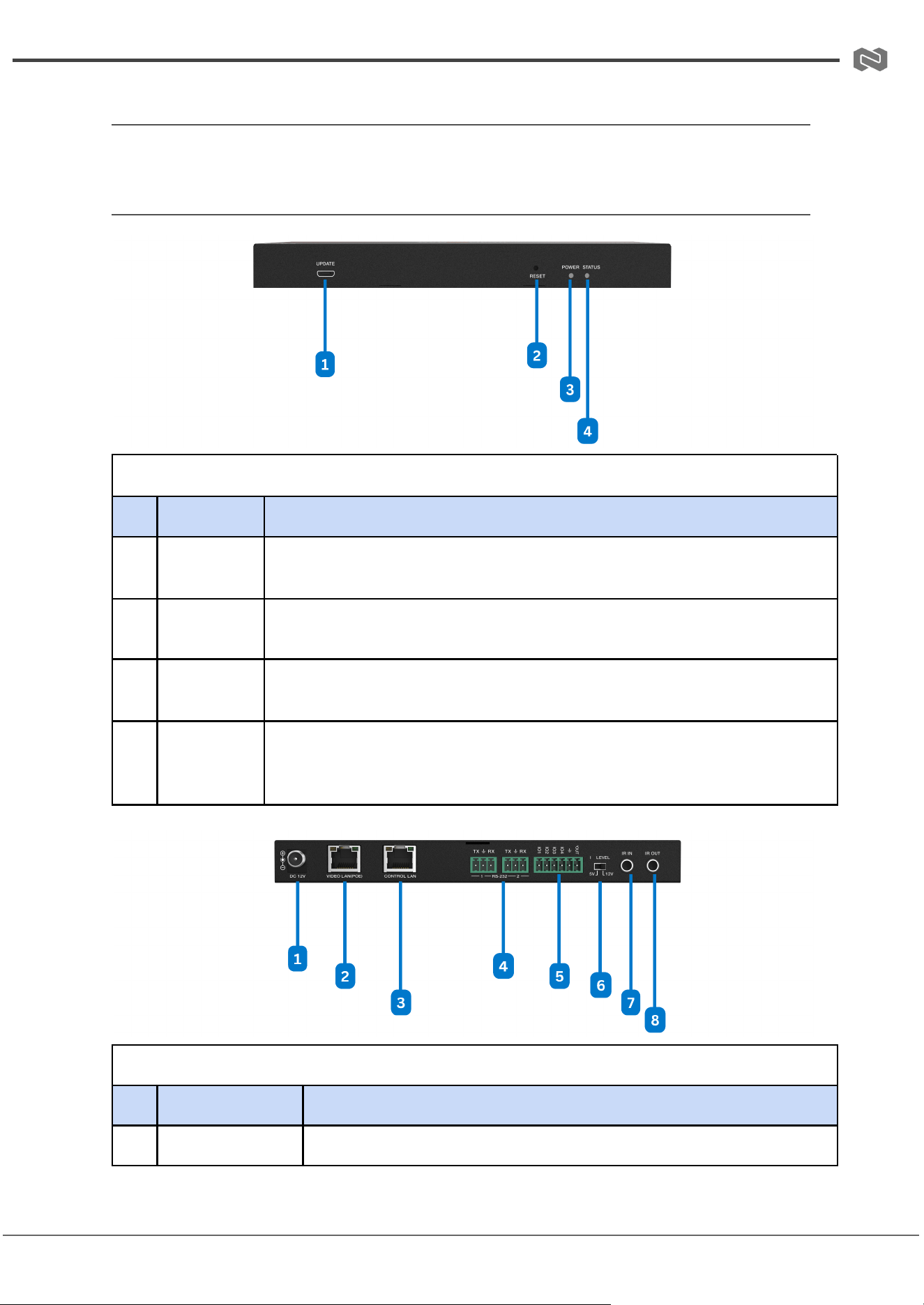
Front and Rear Panel (BG-IPGEAR-ULTRA-C)
Front Panel
No.
Name
Function Description
1
UPDATE
Firmware update port. Note: Must keep no connection on this port when
Controller works in normal mode.
2
RESET
Button
Press and hold this button (about 10 seconds) until STATUS LED starts
flashing, Controller will be reset automatically.
3
POWER
LED
The red LED will light on when the Controller is powered on.
4
STATUS
LED
The status LED will flash in yellowish-green every 1 second until
Controller boots up completely and Control LAN is ready, then it
becomes solid.
Rear Panel
No.
Name
Function Description
1
DC 12V
DC 12V/2.5A power input port.
Address: 830 National Drive #140, Sacramento, CA 95834, USA · Tel: +1(888)499-9906 · Email: support@bzbgear.com 10
BZBGEAR BG-IPGEAR-ULTRA PRODUCT MANUAL
2
VIDEO LAN
(POE)
1G Video LAN port, supporting PoE function. Note: When POE is
enabled, DC 12V/2.5A power supply is not required.
3
CONTROL LAN
The TCP/IP control network port.
4
3-pin Phoenix
Connectors
Two identical RS-232 serial communication ports.
5
6-pin Phoenix
Connector
4 channel I/O level outputs, 1 channel grounding, 1 channel power
supply (supports up to 12V/0.5A) to the outside.
6
IO LEVEL DIP
Switch
Used to control I/O level output and VOUT voltage. Switch to left:
5V I/O level output, VOUT is 5V. Switch to right: 12V I/O level
output, VOUT is 12V.
7
IR IN
12V IR signal input port.
8
IR OUT
5V IR signal output port.
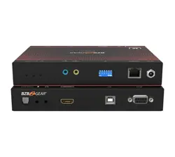
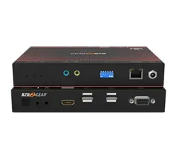
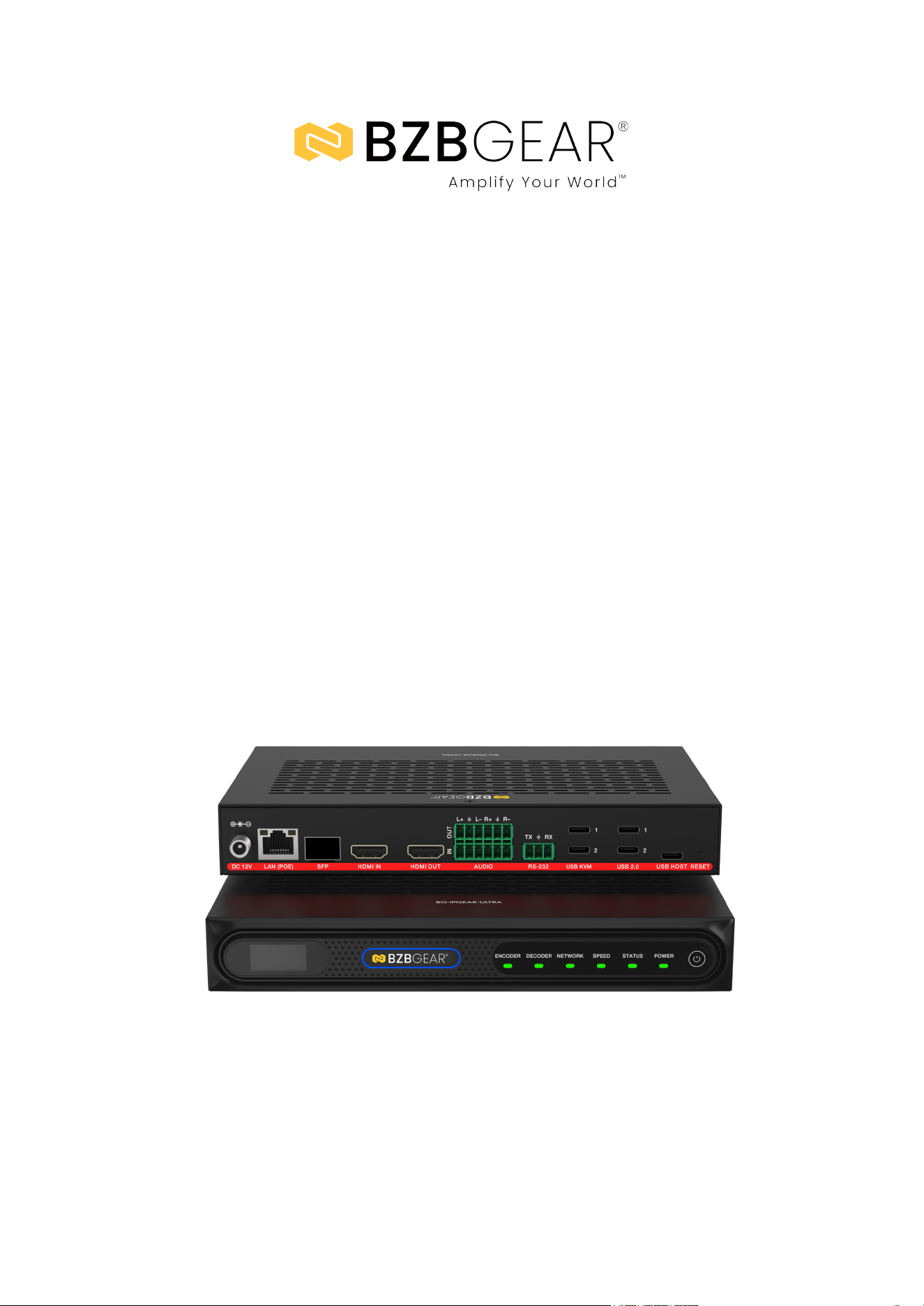
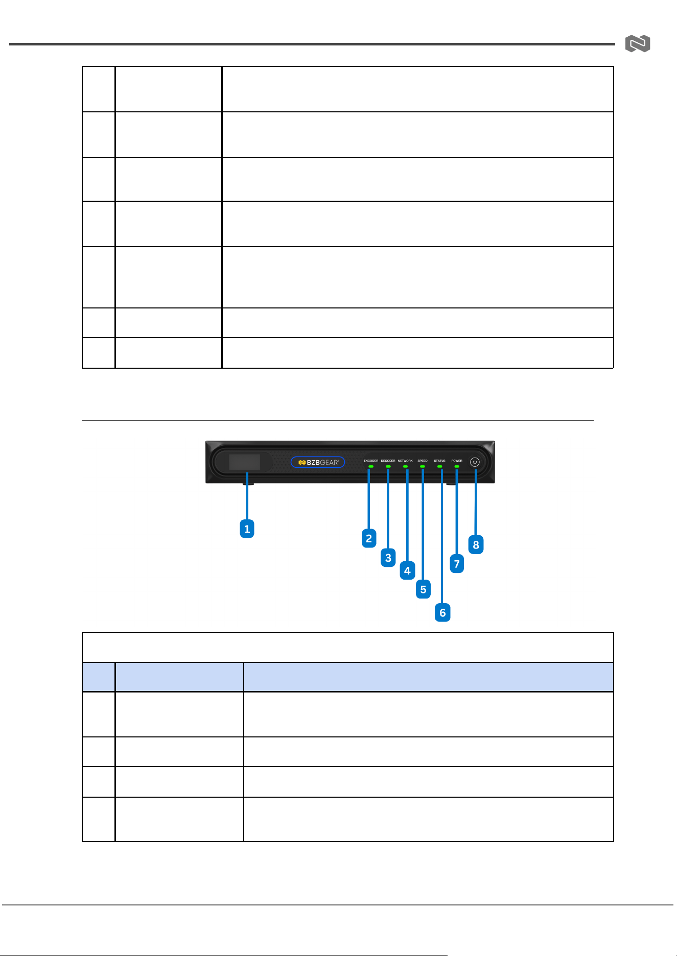
Front and Rear Panel (BG-IPGEAR-ULTRA Transceiver)
Front Panel
No.
Name
Function Description
1
OLED display screen
The name and IP address of the device will be displayed after
the device is turned on. The screen will go off after 90 seconds.
2
ENC LED
The Encoder mode indicator light, normally off.
3
DEC LED
The Decoder mode indicator light, normally off.
4
LINK LED
When the network is connected normally, the green LINK LED
flashes.
Address: 830 National Drive #140, Sacramento, CA 95834, USA · Tel: +1(888)499-9906 · Email: support@bzbgear.com 11
BZBGEAR BG-IPGEAR-ULTRA PRODUCT MANUAL
5
100M(Y)/1000M(G)
LED
Network connection rate indicator:
– When the device is connected to a 100M network, the yellow
indicator is on.
– When the device is connected to a 1000M network, the green
indicator is on.
6
READY LED
– When the system is running normally and no fault occurs, the
green LED is on.
– When the device is in standby mode, the green LED is off.
– If a fault occurs while the system is running, the green LED
flashes at a frequency of 1Hz.
7
POWER LED
– When the device is working normally, the green POWER LED
is on.
– When the device is in standby mode or powered off, the green
POWER LED is off.
8
Power button
The power button supports power-off memory function.
– When the device is working normally, short press the power
button to view the current mode and IP address on the OLED
display screen. Press and hold the power button for more than
2 seconds to turn off the device.
– When the device is off, press the power button to turn the
device on.
– When the device is in standby mode, power off and power on
again, it will enter the standby mode automatically.
– When the two power supply modes are used at the same
time, the local DC 12V power supply is preferred.
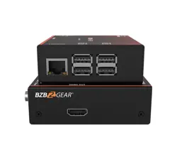
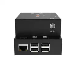
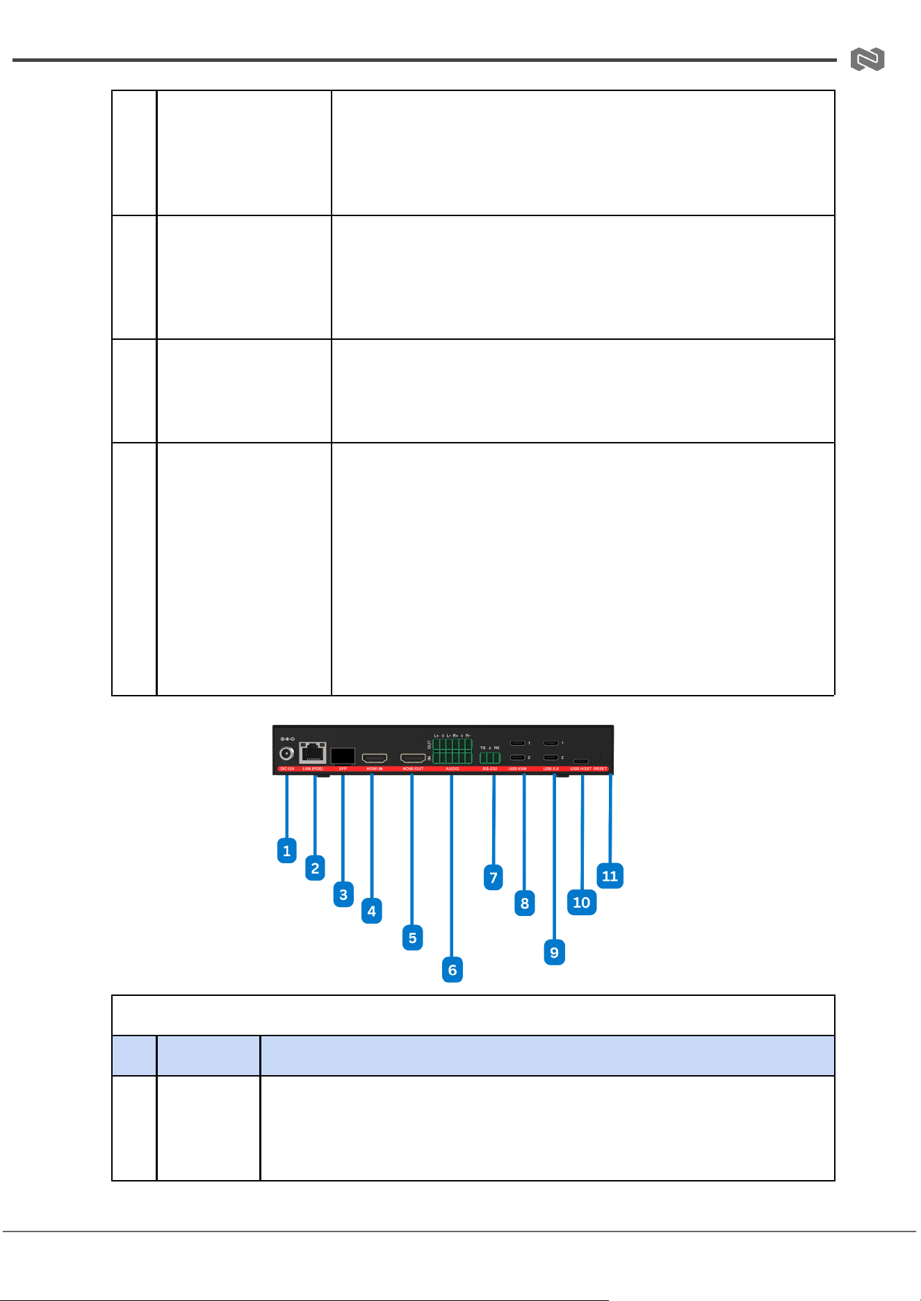
Rear Panel
No.
Name
Function Description
1
DC 12V
DC 12V/2.5A power input port.
Note: The device can be powered via two methods: (a) Local DC 12V
power supply, (b) POE from Network Switch. Device acts as PD mode.
Address: 830 National Drive #140, Sacramento, CA 95834, USA · Tel: +1(888)499-9906 · Email: support@bzbgear.com 12

BZBGEAR BG-IPGEAR-ULTRA PRODUCT MANUAL
When the two power supply modes are used at the same time, the local
DC 12V power supply is preferred.
2
LAN (POE)
port
RJ45 network control port, supporting POE power supply.
3
SFP port
1G fiber optical port.
4
HDMI IN
port
HDMI 2.0 input
5
HDMI OUT
port
Alternate port.
6
AUDIO
IN/OUT
port
Alternate port.
7
RS-232
port
RS-232 serial port, relay RS-232 command transmission from the Control
Server.
8
USB KVM
Alternate port.
9
USB 2.0
Alternate port.
10
USB HOST
Alternate Port
11
RESET
button
System reset button. Long press this button for 5 seconds and reboot the
device manually, the system will be restored to the factory default setting.
Address: 830 National Drive #140, Sacramento, CA 95834, USA · Tel: +1(888)499-9906 · Email: support@bzbgear.com 13
BZBGEAR BG-IPGEAR-ULTRA PRODUCT MANUAL
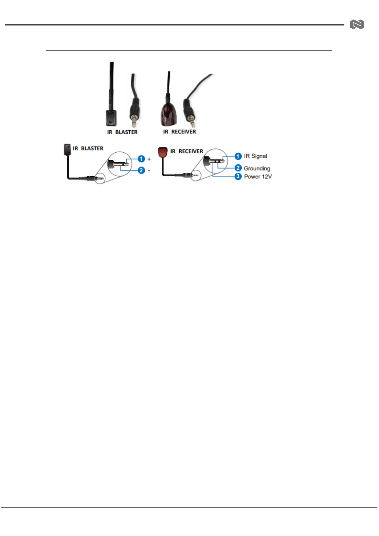
IR Pin Definition (BG-IPGEAR-ULTRA-C)
Address: 830 National Drive #140, Sacramento, CA 95834, USA · Tel: +1(888)499-9906 · Email: support@bzbgear.com 14
BZBGEAR BG-IPGEAR-ULTRA PRODUCT MANUAL
Web GUI Setup (BG-IPGEAR-ULTRA-C)
Step 1: Open a web browser on your PC and enter the Controller’s default IP address or
URL in the address bar:
● Control LAN port: 192.168.6.100
● Video LAN port: 169.254.8.100
● URL: http://controller.local
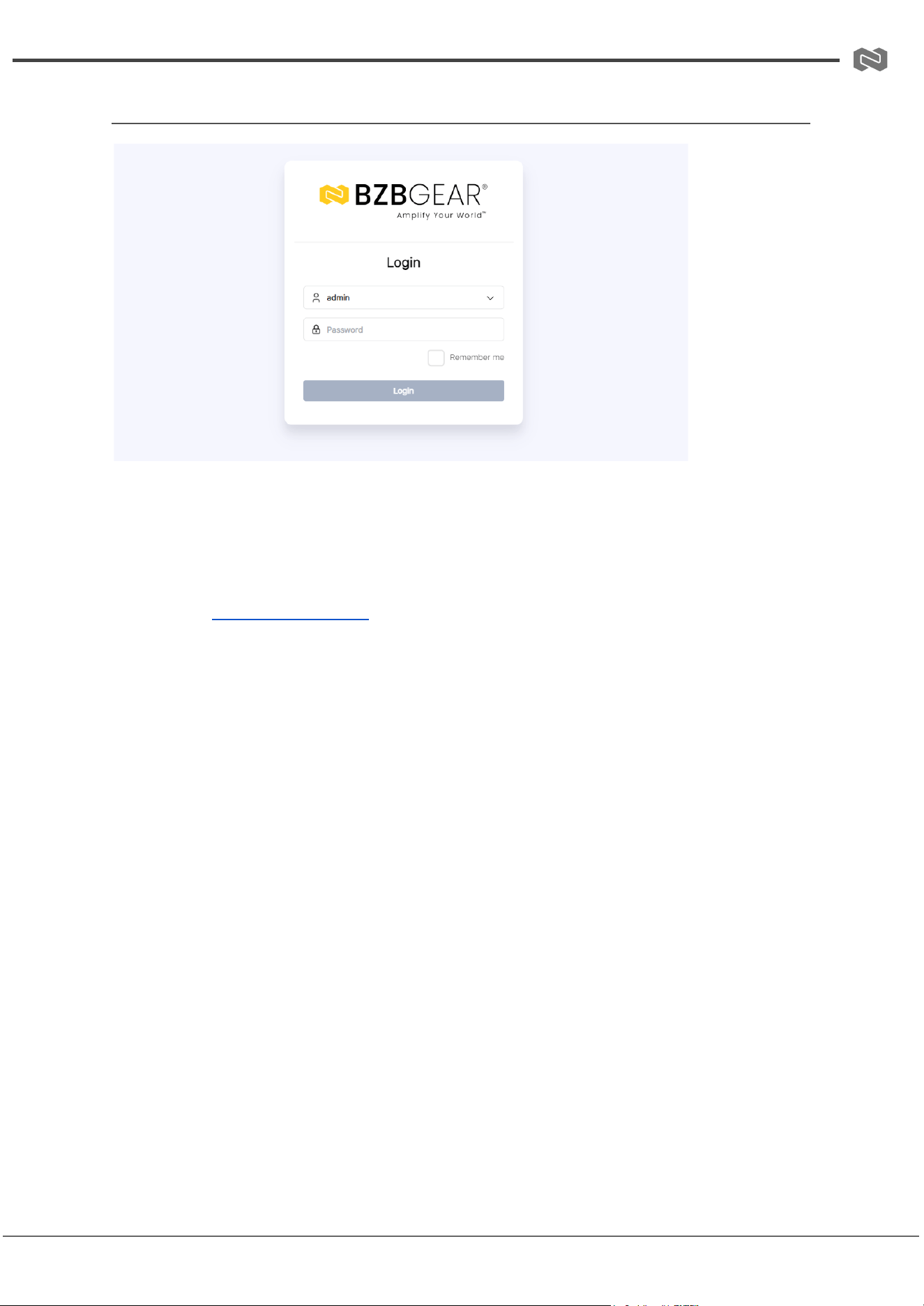
This will take you to the Web GUI login page.
When logging in for the first time:
● Username: admin
● Password: 1234
● Select your preferred language
Click Login to continue. You will then be prompted to change the default password.
Important: Please set a six-digit password using letters or numbers. Use this new
password to log in to the Web GUI.
Step 2: On the initial setup page, click Close to load an existing system (If Applicable)
directly in the web page, or click Next to continue with system setup.
Step 3: Select Automatically managed by Controller Box as the IP mode for the Video LAN.
In this mode, the Controller automatically assigns IP addresses to the Video LAN port,
Encoder, and Decoder.
Select “Automatically add Encoders and Decoders to system”, and click the “Next” button
to enter the Device page. The system starts to search for devices. All the connected
devices will be searched and added to the system (presented in the Encoder/Decoder list)
automatically.
Address: 830 National Drive #140, Sacramento, CA 95834, USA · Tel: +1(888)499-9906 · Email: support@bzbgear.com 15
BZBGEAR BG-IPGEAR-ULTRA PRODUCT MANUAL
Web GUI Functions and Operations (BG-IPGEAR-ULTRA-C)
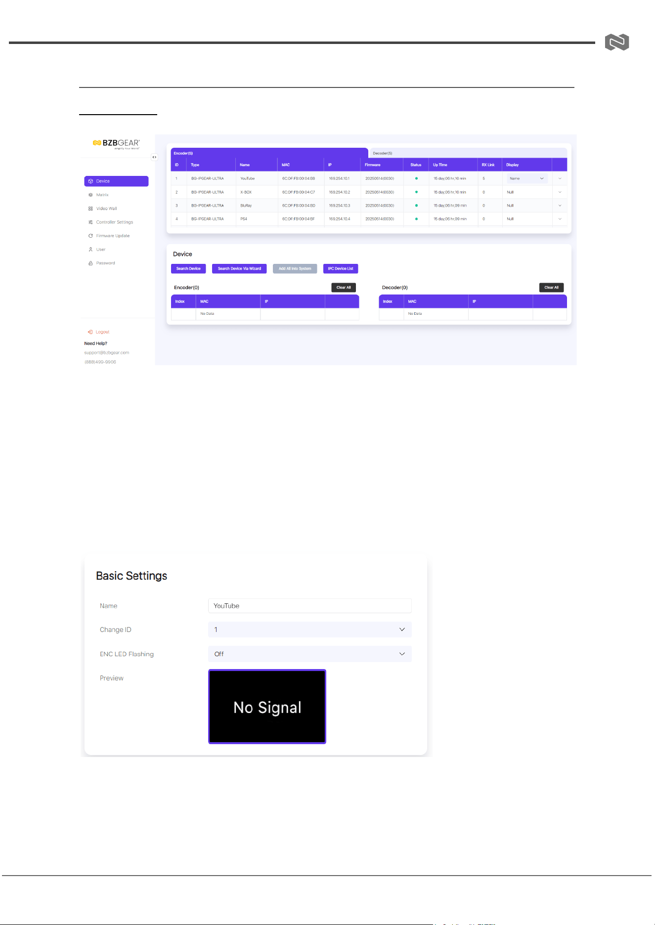
Device Page
On this page, click the Encoder/Decoder tab to view detailed information about all
Encoders and Decoders in the system. The available information includes: ID, Name, MAC
Address, IP Address, Firmware Version, Online/Offline Status, Up Time, RX Link, and
Member/Source.
You can also configure individual Encoders or Decoders by clicking the drop-down icon
located to the left of the ID field.
Encoder Configuration
Basic Settings
1. Name: Allows you to rename the Encoder.
○ Maximum length: 16 characters
Address: 830 National Drive #140, Sacramento, CA 95834, USA · Tel: +1(888)499-9906 · Email: support@bzbgear.com 16
BZBGEAR BG-IPGEAR-ULTRA PRODUCT MANUAL
○ Special characters are not supported
2. Change ID: Assign a unique ID to the Encoder.
○ Valid range: 1–762
○ Note: Both the ID and Name must be unique.
3. ENC LED: Activates the “Show Me” function to quickly identify the device.
○ Use the drop-down menu to turn the front panel LED On/Off.
4. Preview: Displays a preview of the Encoder’s video stream.
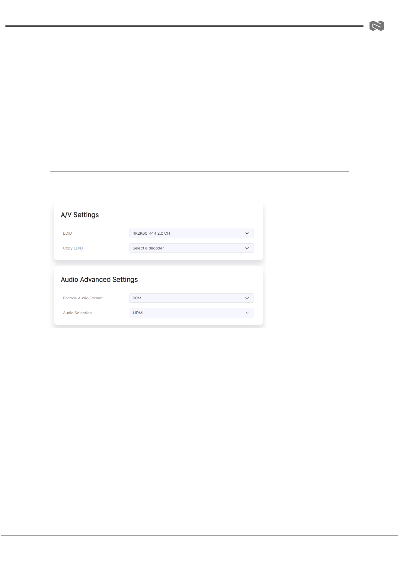
A/V Settings
1. EDID: Use the drop-down menu to select the EDID for the Encoder.
2. Copy EDID: Select a Decoder from the drop-down menu to copy its EDID settings.
3. Audio Selection: Choose the audio input source:
○ HDMI – The Encoder’s HDMI input is used as the audio source for the
Decoder’s audio output.
○ Analog – The Encoder’s analog audio input is used as the audio source for
the Decoder’s audio output.
Video Advanced Settings
Address: 830 National Drive #140, Sacramento, CA 95834, USA · Tel: +1(888)499-9906 · Email: support@bzbgear.com 17
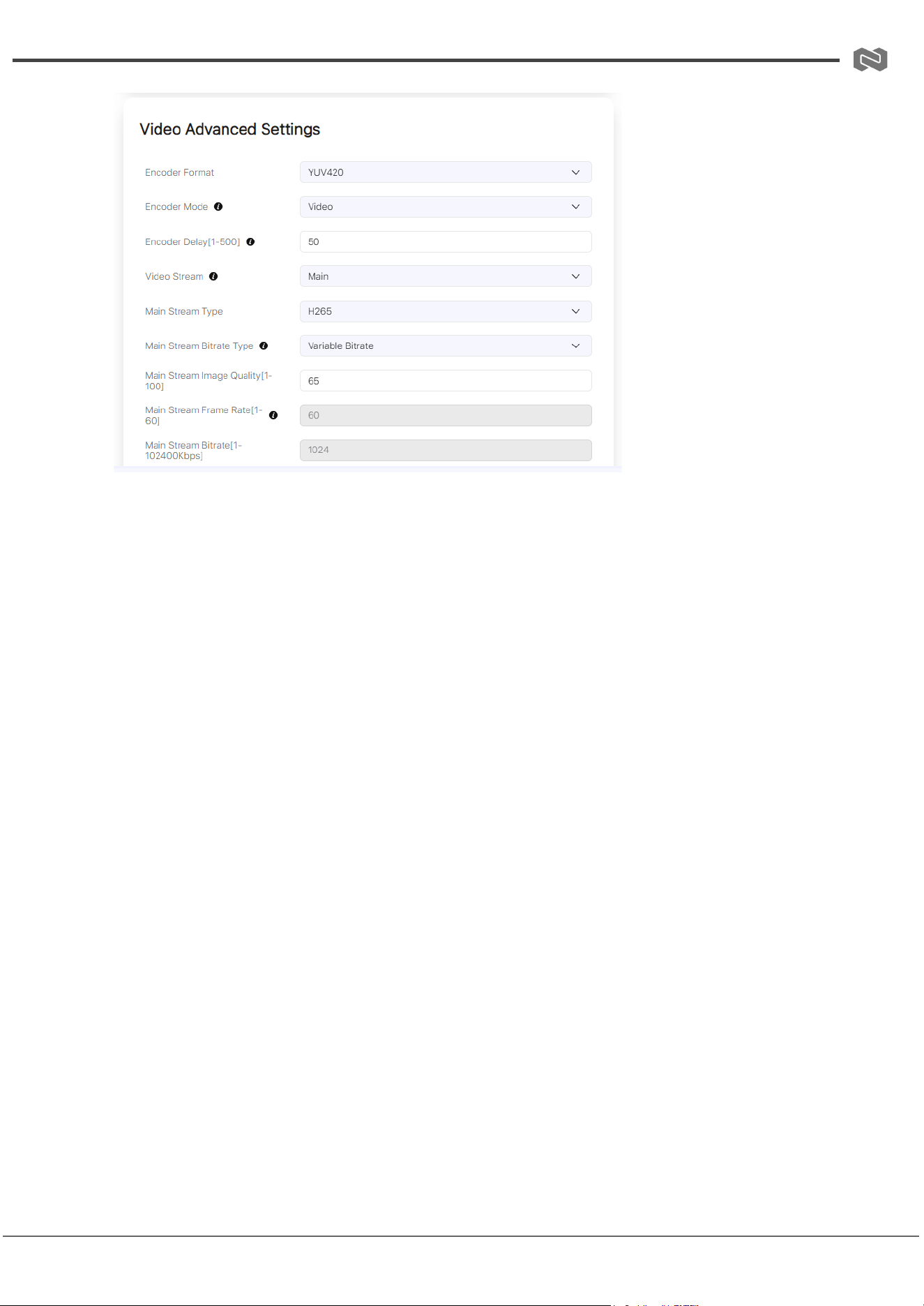
BZBGEAR BG-IPGEAR-ULTRA PRODUCT MANUAL
1. Encoder Format: Select the encoder format from the drop-down menu.
2. Encoder Mode: Choose the encoder mode (Video/Text).
3. Encoder Delay [50–500]: Enter a value between 50–500 to set the encoder delay.
4. Video Stream: Select the desired video stream (Main / Sub / Preview / SDK / SDK
Sub).
5. Main Stream Type: Choose the video encoding format for the main stream (H.264 /
H.265).
6. Main Stream Frame Rate [1–120]: Enter a value between 1–120 to set the frame
rate.
7. Main Stream Bitrate Type: Select the bitrate type (Fixed / Variable).
8. Main Stream Bitrate [1–102400]: Enter a value between 1–102400 to set the
bitrate.
9. Main Stream Image Quality [1–100]: Enter a value between 1–100 to adjust image
quality.
Audio Advanced Settings
1. Audio Format: Select the audio encoding format (PCM / AAC).
2. Audio Interface: Choose the audio input interface (HDMI / Analog).
Address: 830 National Drive #140, Sacramento, CA 95834, USA · Tel: +1(888)499-9906 · Email: support@bzbgear.com 18
BZBGEAR BG-IPGEAR-ULTRA PRODUCT MANUAL
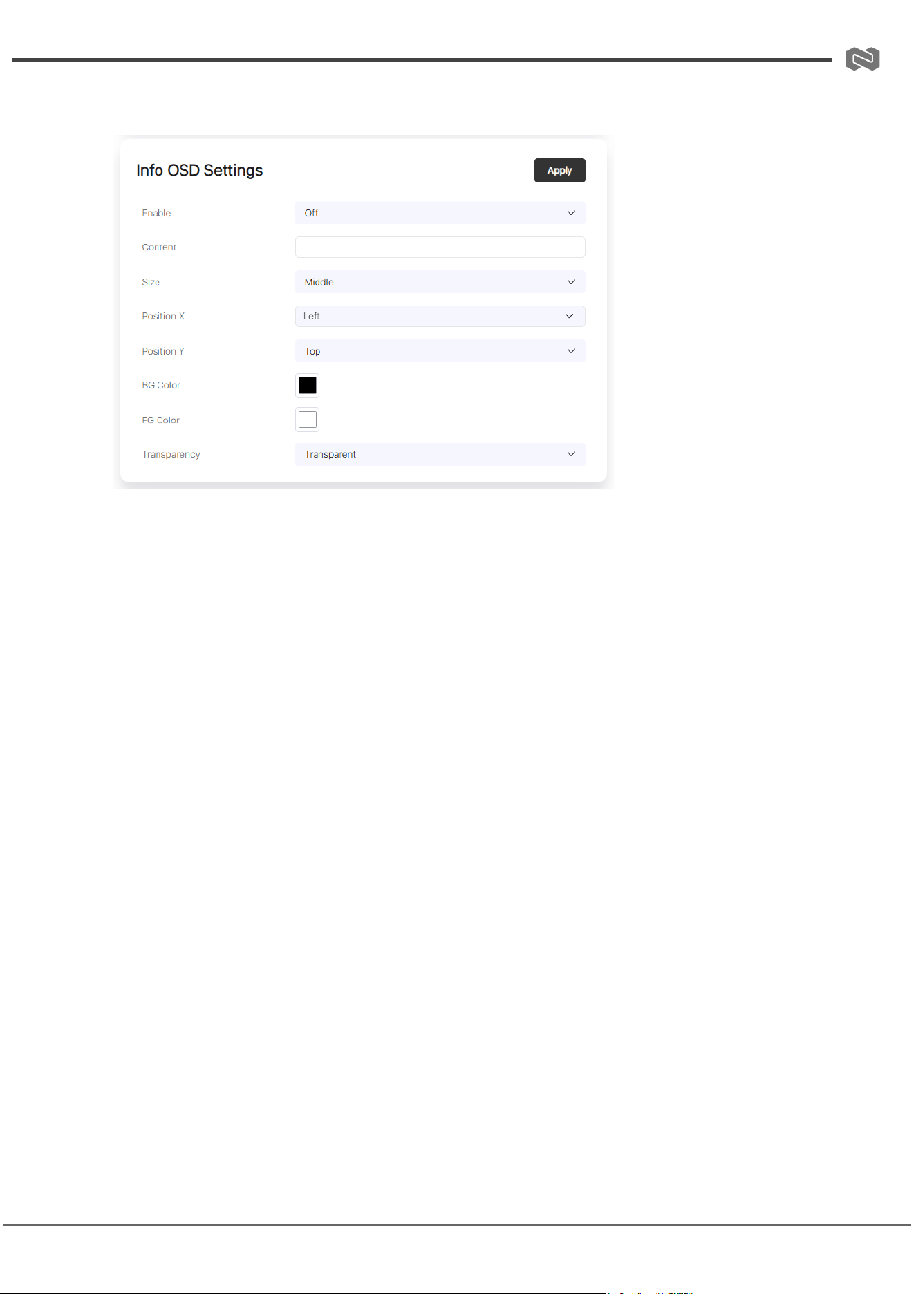
OSD Settings
1. Content: Enter the text to display in the OSD.
2. Size: Select the OSD size (Small / Medium / Large).
3. Position X: Choose the horizontal position of the OSD (Left / Center / Right).
4. Position Y: Choose the vertical position of the OSD (Top / Center / Bottom).
5. Background Color: Set the OSD background color.
6. Foreground Color: Set the OSD foreground (text) color.
7. Transparency: Select the OSD transparency type (Transparent / Opaque).
8. Enable: Toggle On/Off to enable or disable the OSD display.
Other Settings
1. Encode Sync Level: Select the sync level (Low / Medium / High).
2. KVM OS Select: Choose the operating system for KVM control (Linux / Windows /
macOS).
3. Transfer Type: Toggle On/Off to enable or disable multicast transfer.
Address: 830 National Drive #140, Sacramento, CA 95834, USA · Tel: +1(888)499-9906 · Email: support@bzbgear.com 19
BZBGEAR BG-IPGEAR-ULTRA PRODUCT MANUAL
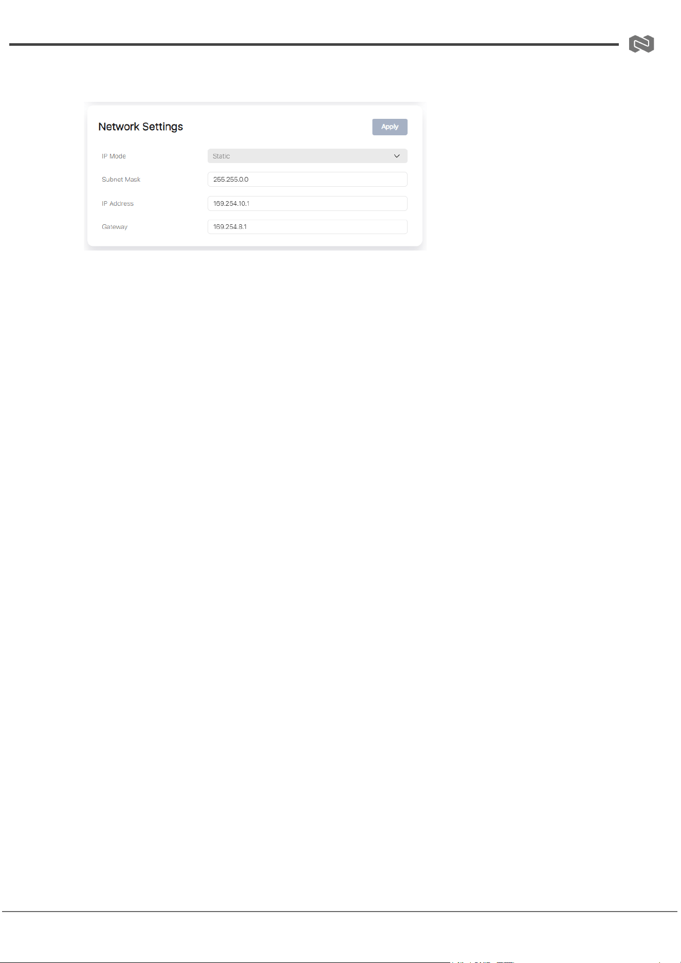
Network Settings
1. IP Mode: Select the IP mode (Static / DHCP).
2. IP Address: Displays or sets the IP address of the encoder.
3. Subnet Mask: Displays or sets the subnet mask of the encoder.
4. Gateway: Displays or sets the gateway of the encoder.
Notes:
● If IP Mode is set to Static, you can manually configure the IP Address, Subnet Mask,
and Gateway. Click Apply to confirm changes.
● If IP Mode is set to DHCP, the encoder will automatically obtain an IP address from
the router.
● If the encoder is online but configured with an incorrect network segment, it may
appear as “offline.” In this case, you can still modify its network settings (including IP
address).
Additional Functions
● Reboot: Restarts the encoder.
● Replace: Reserved for device replacement (not active).
● Remove: Removes the selected encoder from the system.
● Remove All: Removes all encoders from the system.
● Factory Reset: Restores the encoder to factory default settings.
● Switch to Decoder: Switches the encoder to decoder mode.
○ A confirmation prompt will appear. Selecting Yes removes the encoder from
the current system. You will need to run a Scan to add it back again.
Address: 830 National Drive #140, Sacramento, CA 95834, USA · Tel: +1(888)499-9906 · Email: support@bzbgear.com 20
BZBGEAR BG-IPGEAR-ULTRA PRODUCT MANUAL
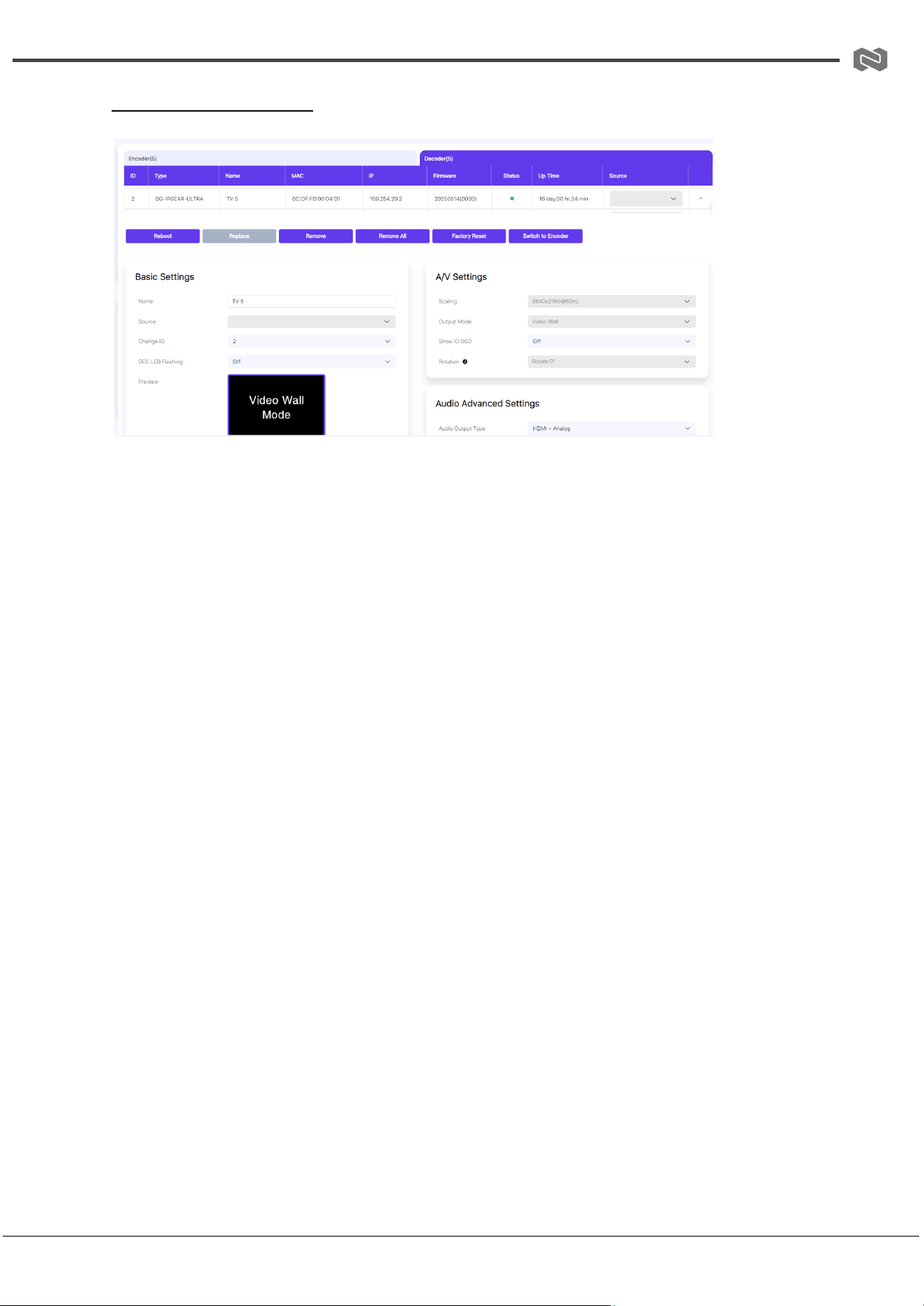
Decoder Configuration
Basic Settings
1. Name: Set the decoder name (max. 16 characters, no special characters).
○ Note: Decoder name and ID must not be duplicated.
2. Source: Select the signal source for the decoder from the drop-down menu.
3. Change ID: Assign an ID to the decoder (range: 1–762).
4. DEC LED: Enables the “Show Me” function to help locate the decoder. Select
On/Off to toggle the front-panel LED.
5. Preview: Displays a live preview of the decoder.
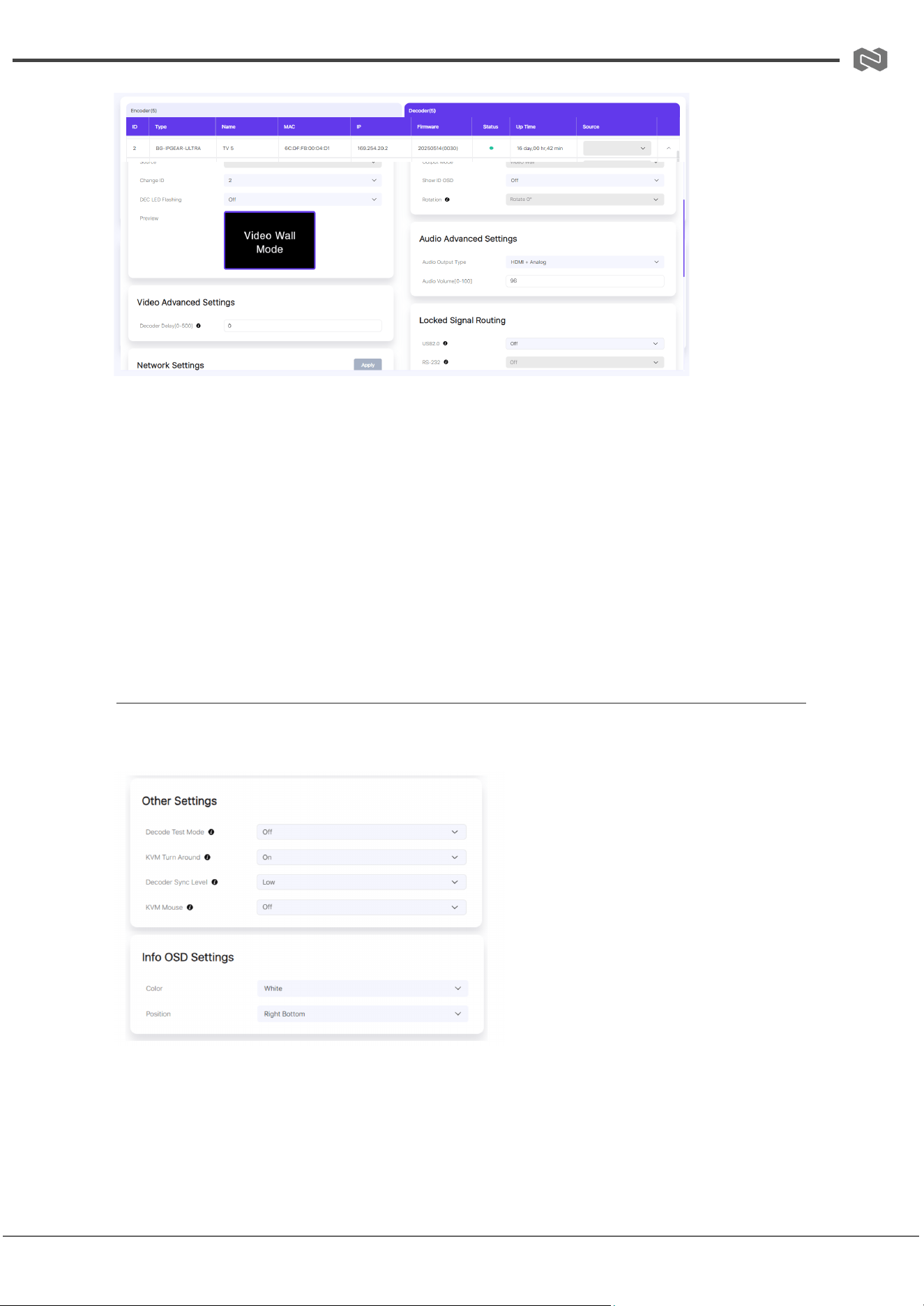
Decoder Configuration
Audio/Video Settings
● Video Advanced Settings
1. Decoder Format: Select the decoder format from the drop-down menu.
2. Decoder Delay [0–500]: Enter a value between 0–500 to set the decoder
delay.
● Output Settings
1. Output Mode: Displays the current output mode (Matrix / Video Wall).
2. Scaling: Select the video output resolution from the drop-down menu.
Address: 830 National Drive #140, Sacramento, CA 95834, USA · Tel: +1(888)499-9906 · Email: support@bzbgear.com 21
BZBGEAR BG-IPGEAR-ULTRA PRODUCT MANUAL
Video Advanced Settings
1. Decoder Format: Select the desired decoder format from the drop-down menu.
2. Decoder Delay [0–500]: Enter a value between 0 and 500 to configure the decoder
delay.
3. Output Mode: Displays the current video output mode (Matrix/Video Wall).
4. Scaling: Select the preferred video output resolution from the drop-down menu.
Audio Advanced Settings
1. Audio Output Type: Choose the audio output type (HDMI/DVI) from the drop-down
menu.
2. Audio Volume [0–100]: Enter a value between 0 and 100 to set the output volume.
OSD & Other Settings
OSD Settings
1. Color: Set the OSD color (White/Black).
2. Position: Choose the OSD display position from the drop-down menu (Top Left /
Top Right / Bottom Left / Bottom Right).
Address: 830 National Drive #140, Sacramento, CA 95834, USA · Tel: +1(888)499-9906 · Email: support@bzbgear.com 22
BZBGEAR BG-IPGEAR-ULTRA PRODUCT MANUAL
3. Show ID OSD: Toggle On/Off to enable or disable the ID display on the OSD.
Other Settings
1. Decode Test Mode: Select the desired test mode from the drop-down menu (Off /
Gray / Color / Geo / Message / White / Red / Green).
2. Decoder Sync Level: Choose the sync level (Low / Medium / High).
3. KVM Turn Around: Toggle On/Off to enable or disable the KVM turn-around
function.
4. KVM Mouse: Toggle On/Off to enable or disable KVM mouse control.
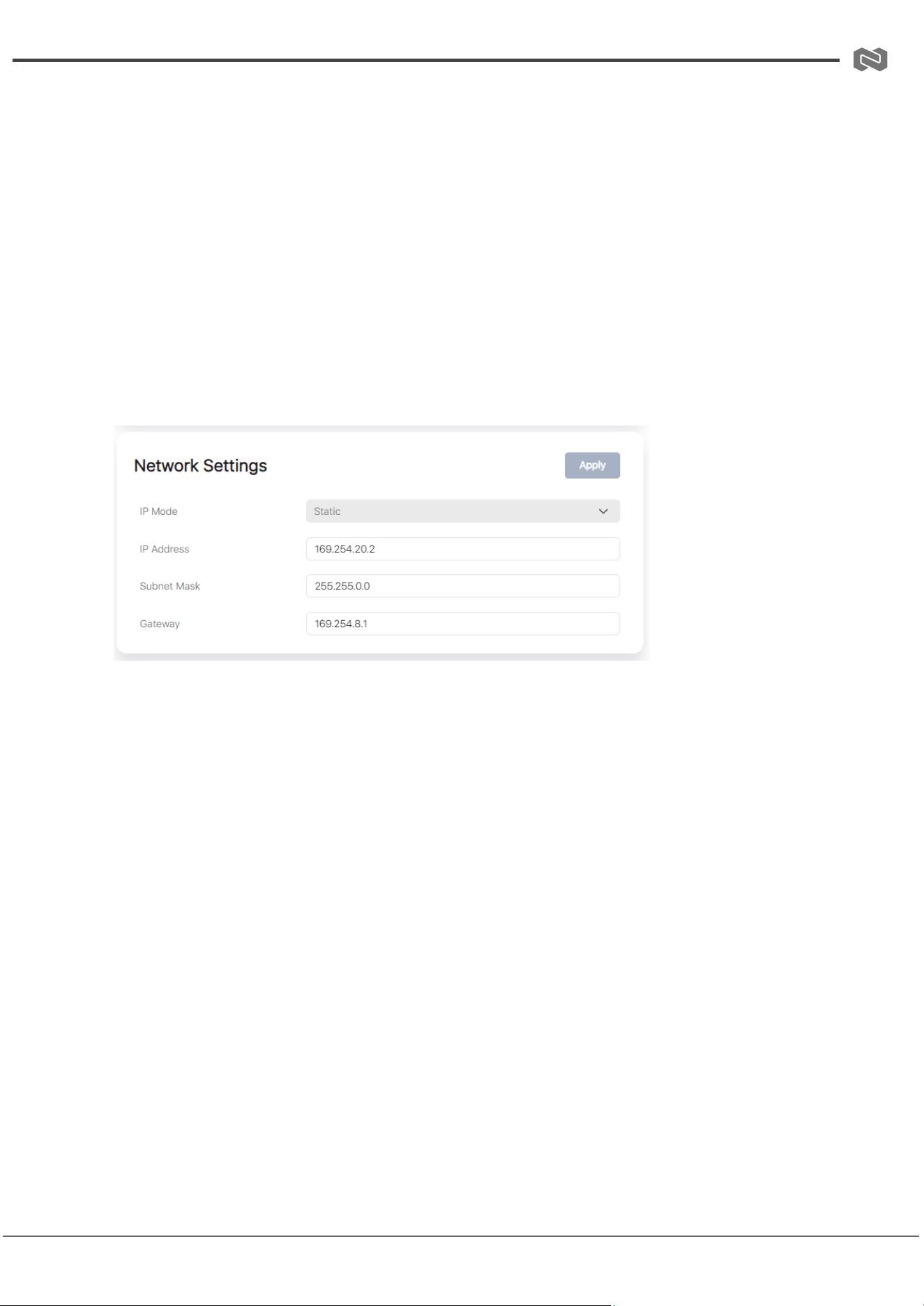
Network Settings
1. IP Mode: Select the IP mode (Static/DHCP) from the drop-down menu.
2. IP Address: Displays or allows entry of the decoder’s IP address.
3. Subnet Mask: Displays or allows entry of the decoder’s subnet mask.
4. Gateway: Displays or allows entry of the decoder’s gateway address.
Notes:
● If Static is selected, you can manually configure the IP Address, Subnet Mask, and
Gateway. Click Apply for changes to take effect.
● If DHCP is selected, the decoder will automatically obtain its IP Address from the
router.
● If the decoder is active but configured with an incorrect network segment, it may
appear offline. However, its network settings (including IP address) can still be
modified.
Address: 830 National Drive #140, Sacramento, CA 95834, USA · Tel: +1(888)499-9906 · Email: support@bzbgear.com 23
BZBGEAR BG-IPGEAR-ULTRA PRODUCT MANUAL
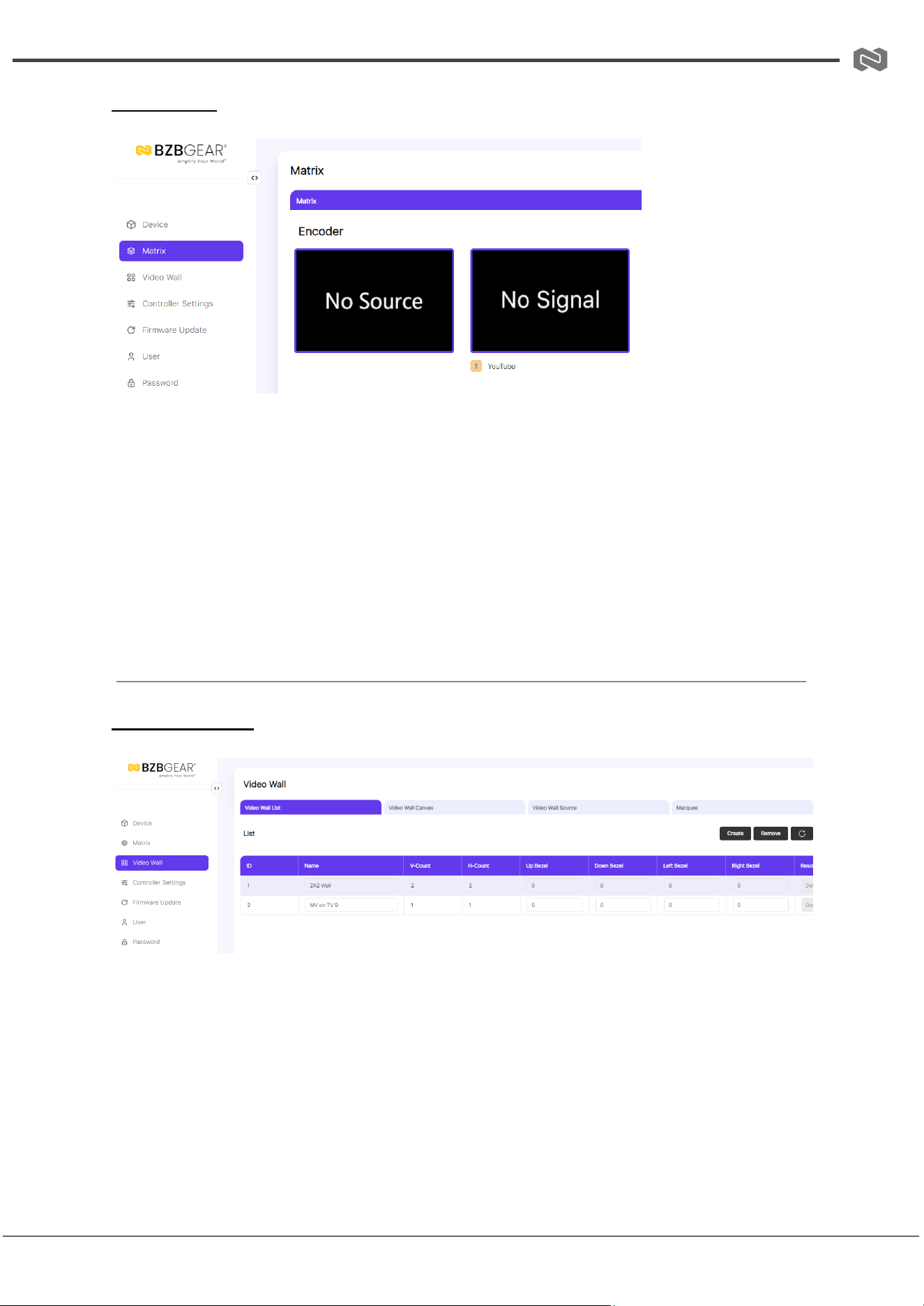
Matrix Page
Matrix Switching Function
① To perform one-to-one switching, left-click an Encoder, drag it to a Decoder, and release
the mouse.
② To perform one-to-all switching, left-click an Encoder, drag it to All Decoders, and
release the mouse.
③ To perform one-to-many switching, left-click an Encoder, drag it to multiple Decoders,
and release the mouse.
Video Wall Page
Video Wall Creation
On the Video Wall List page, you can create and configure video walls as needed. Follow
the steps below:
Step 1: Create a Video Wall
● Click “Create”. A dialog box will appear.
● Set the Video Wall ID, Name, Row Number, Column Number, and Resolution.
● Click “Go” to create the video wall.
Address: 830 National Drive #140, Sacramento, CA 95834, USA · Tel: +1(888)499-9906 · Email: support@bzbgear.com 24
BZBGEAR BG-IPGEAR-ULTRA PRODUCT MANUAL
● If Custom Resolution is selected, you can configure additional settings as shown in
the example figure.
Note: The video wall name can be modified after creation.
Step 2: Assign Decoders
● Select the video wall you want to configure.
● Click “Assign Decoder” at the bottom of the Video Wall List page.
● In the assignment interface, click each screen and choose the corresponding
Decoder device.
● Click “Apply” to save the configuration.
Note: A Decoder can only be assigned to one video wall.
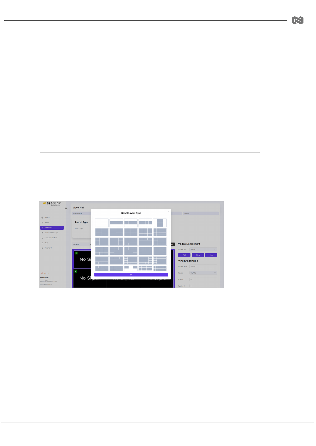
Video Wall Canvas
After creating and configuring a video wall, click the Video Wall Canvas tab to adjust the
layout, create and manage presets, and configure windowing options.
(1) Video Wall Layout
Follow these steps to set up the video wall layout:
Step 1: Select Layout
● In the Layout Type area, click the desired layout.
● The selected layout will appear in the video wall canvas.
Step 2: Configure Windows
● Click a window in the layout to edit it.
● In the Window Settings area, you can rename the window, select a source, and
adjust its position, width, and height.
● Alternatively, drag the window directly on the canvas to resize or reposition it.
Address: 830 National Drive #140, Sacramento, CA 95834, USA · Tel: +1(888)499-9906 · Email: support@bzbgear.com 25
BZBGEAR BG-IPGEAR-ULTRA PRODUCT MANUAL
● Click “Apply” to confirm and save the changes.
Step 3: Assign Sources and Save Preset
● Repeat the process to assign signal sources and adjust the size/position for each
window as needed.
● Once complete, click “Apply” above the video wall canvas to save the configuration
as Preset 1 and activate it.
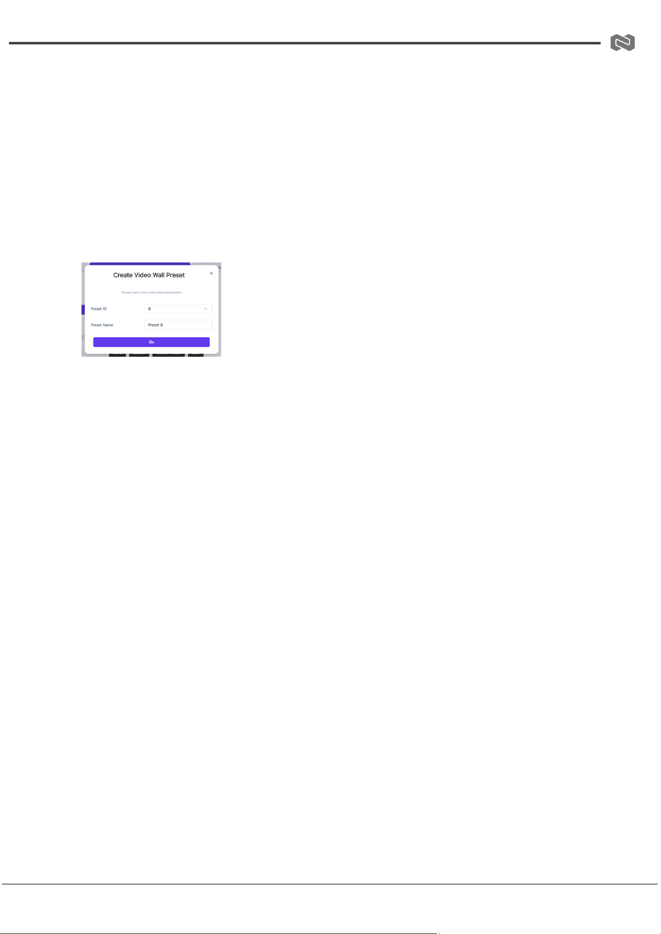
(2) Preset Creation
Follow these steps to create and configure a video wall preset:
Step 1: Create a Preset
● Click “Create Preset”. A dialog box will appear.
● Set the Preset ID and Name, then click “Go” to create the preset.
Step 2: Configure the Layout
● In the Layout Type area, select the desired layout and configure the windows as
needed.
● Click “Apply” above the video wall canvas to save the preset.
(3) Windowing Configuration
Follow these steps to create and configure windowing:
Step 1: Add a Window
● In the Window Management area, click “Add”. A dialog box will appear.
● Set the ID, Name, Source, Position, and Size, then click “Go”.
● The newly created window will appear on top of the video wall.
Step 2: Manage Windows
● To add more windows, repeat the process above.
● To adjust a window, select it and drag to reposition or resize.
● To delete a window, select it in the Window List, click “Delete”, and confirm by
clicking “Yes”.
● To remove all windows, click “Clear”. Use this option with caution.
Additional Options:
Address: 830 National Drive #140, Sacramento, CA 95834, USA · Tel: +1(888)499-9906 · Email: support@bzbgear.com 26

BZBGEAR BG-IPGEAR-ULTRA PRODUCT MANUAL
● Adjust window layering using “Bring to Top” or “Bring to Bottom” in the Window
Layer area.
● Upload a background image in the Background Full Image area.
● Click “Drag” above the video wall canvas to reposition the video wall within the
canvas for better preview.
Address: 830 National Drive #140, Sacramento, CA 95834, USA · Tel: +1(888)499-9906 · Email: support@bzbgear.com 27
BZBGEAR BG-IPGEAR-ULTRA PRODUCT MANUAL
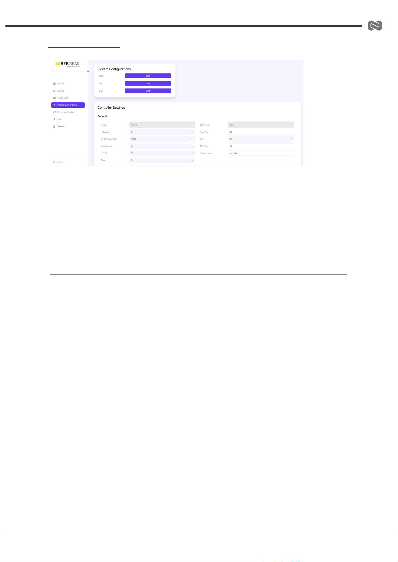
Controller Settings
System Configurations
● Save: Click to save the current system configuration.
● Load: Click to load a saved configuration file, replacing the current system settings.
(It is strongly recommended to save the current configuration before loading a new
one.)
● Clear: Click to clear all configurations currently set in the Controller. After clearing,
the system must be set up again.
Controller Settings
① General
General settings of the Controller include:
● Viewing the Controller Version and GUI Version
● Configuring Telnet Port, SSH Port, and Domain Name
● Setting control options via drop-down menus: IR Control, RS-232 Baud Rate, Web
Control, HTTPS, Telnet, and SSH
② Control Network
This configures the network port for connecting the Controller to a router, PC, or network
switch (where the control PC is located):
● DHCP Off: Manually set IP Address, Subnet Mask, and Gateway, then click Apply.
● DHCP On: The system automatically obtains an IP Address assigned by the router.
③ Video Network
This configures the network port connected to the network where Encoders and Decoders
reside.
Note: Modification of this network is currently not supported.
Address: 830 National Drive #140, Sacramento, CA 95834, USA · Tel: +1(888)499-9906 · Email: support@bzbgear.com 28

BZBGEAR BG-IPGEAR-ULTRA PRODUCT MANUAL
④ Controller Reset
● Settings Reset: Resets all Controller settings except network settings.
● Network Reset: Resets only the Controller’s network settings.
● Reset All: Resets all Controller settings, including network settings.
Note: After modifying any Controller settings on this page, the Controller will automatically
reboot to apply changes.
Address: 830 National Drive #140, Sacramento, CA 95834, USA · Tel: +1(888)499-9906 · Email: support@bzbgear.com 29
BZBGEAR BG-IPGEAR-ULTRA PRODUCT MANUAL
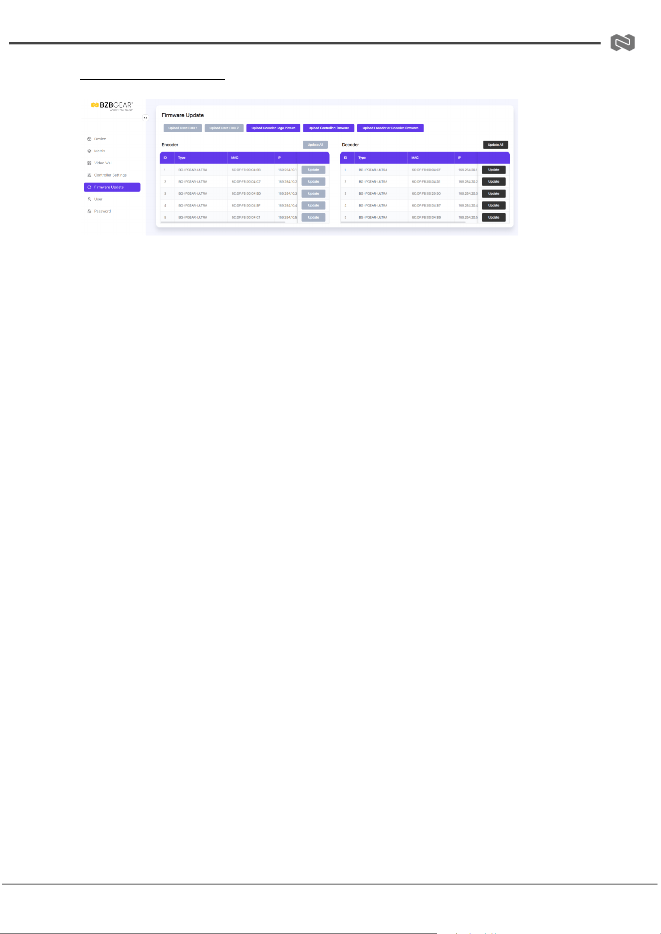
Firmware Update Page
Upload Functions
① Upload User EDID 1/2
Click the button to open an EDID binary file and upload it to User EDID 1/2.
Note: This function is temporarily unavailable.
② Upload Decoder Logo Picture
Click the button to open a BMP picture file and upload it as the Decoder Logo. Then:
● Click Update All to apply the logo to all Decoders.
● Click Update to apply the logo to a single Decoder.
Requirements for the BMP image:
● File size: greater than 500 kB and less than or equal to 25 MB
● Image resolution: between 960×360 and 3840×2160
③ Upload Controller Firmware
Click the button to upload firmware for the Controller.
④ Upload Encoder or Decoder Firmware
Click the button to upload firmware for Encoders or Decoders. After uploading:
● Click Update All to update firmware for all devices.
● Click Update to update firmware for a single device.
Address: 830 National Drive #140, Sacramento, CA 95834, USA · Tel: +1(888)499-9906 · Email: support@bzbgear.com 30
BZBGEAR BG-IPGEAR-ULTRA PRODUCT MANUAL
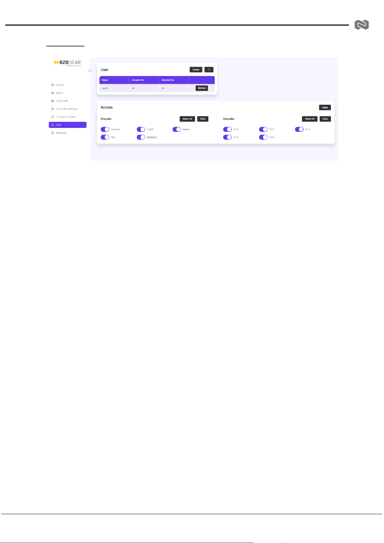
User Page
User Management
On this page, you can create new user accounts with customizable control privileges. This
allows each user to have a unique login and restrict access to specific inputs, outputs, or
functions.
Steps to Create a New User:
Step 1: Click Create. A pop-up dialog box will appear.
Step 2: Enter the following information:
● User Name
● User Password
● Confirm Password
Click Go to create the user.
Notes:
1. User Name: 6–12 characters, no special characters.
2. Password: 6–8 characters. Password and Confirm Password must match.
Assign Device Access:
● After creating a user, select Encoders and Decoders the user can access by
checking devices at the bottom of the page, or click Select All to give access to all
devices.
● Click Apply to save the settings.
Assign KVM Access:
● Click KVM, select the Encoders and Decoders to use for KVM control, then click
Apply.
Other User Management Functions:
Address: 830 National Drive #140, Sacramento, CA 95834, USA · Tel: +1(888)499-9906 · Email: support@bzbgear.com 31

BZBGEAR BG-IPGEAR-ULTRA PRODUCT MANUAL
● Password: Click to change the user’s password.
● Remove: Click to delete the user.
● Login as New User: Click the logout icon at the top right corner, then log in with the
new user credentials.
Address: 830 National Drive #140, Sacramento, CA 95834, USA · Tel: +1(888)499-9906 · Email: support@bzbgear.com 32
BZBGEAR BG-IPGEAR-ULTRA PRODUCT MANUAL
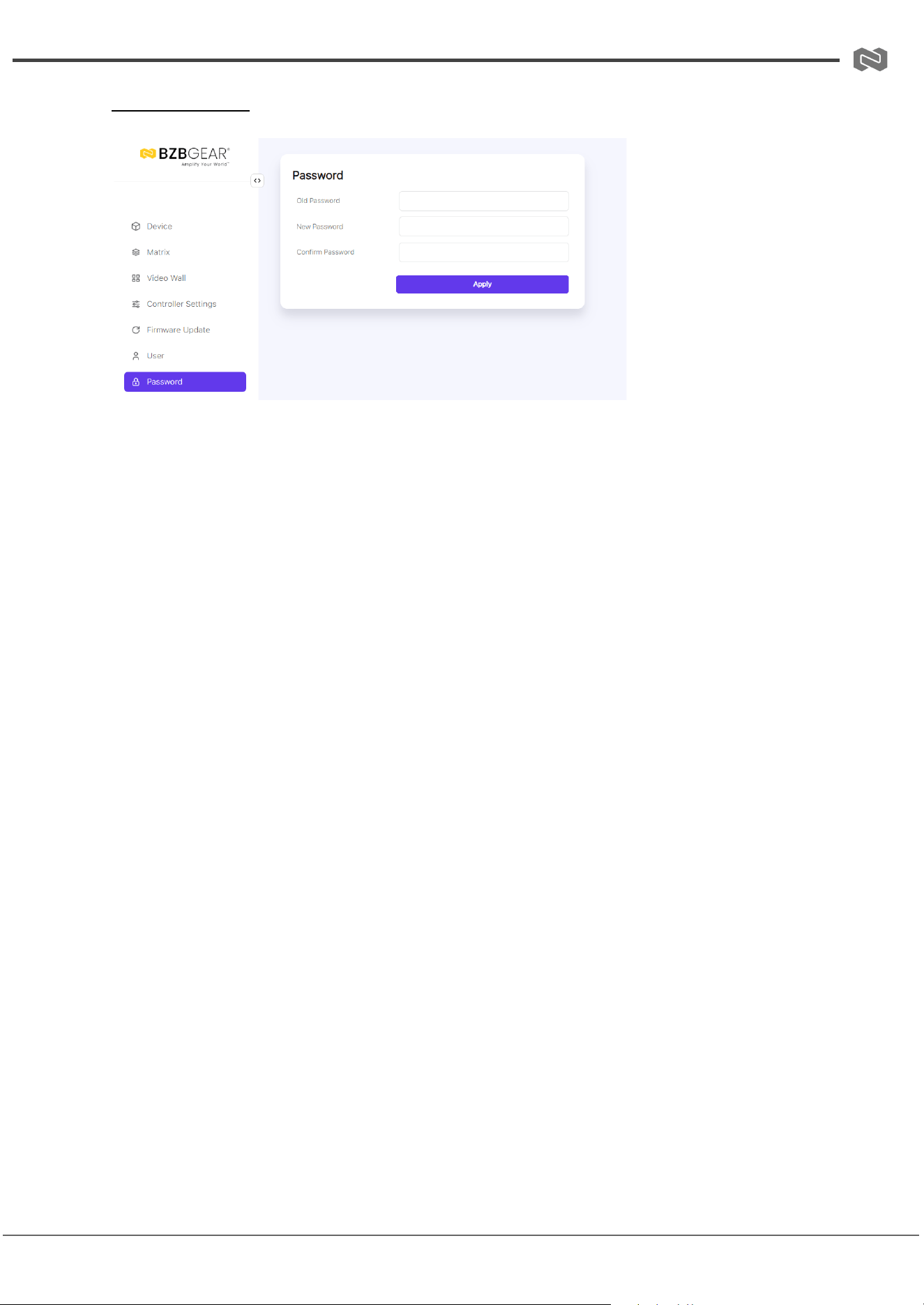
Password Page
Change Password
On this page, you can change your password by entering the following information:
● Old Password
● New Password
● Confirm Password
Click Apply to save the changes.
Notes:
1. Password length must be between 6 and 8 characters. Special characters are not
supported.
2. The New Password cannot be the same as the Old Password.
3. New Password and Confirm Password must match.
4. After changing the password, the system will automatically return to the Web GUI
login interface. You will need to log in again using the new password.
Additionally, a logout icon is located in the upper-right corner of every Web GUI page.
Clicking this icon will exit the Web GUI and automatically return you to the login interface.
Address: 830 National Drive #140, Sacramento, CA 95834, USA · Tel: +1(888)499-9906 · Email: support@bzbgear.com 33
BZBGEAR BG-IPGEAR-ULTRA PRODUCT MANUAL
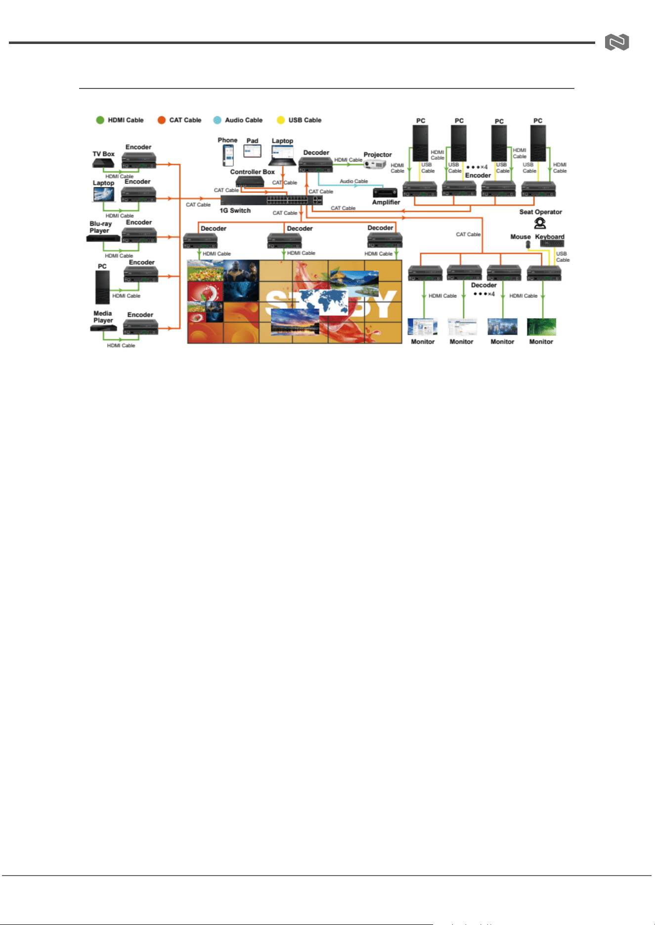
Connection Diagram
Address: 830 National Drive #140, Sacramento, CA 95834, USA · Tel: +1(888)499-9906 · Email: support@bzbgear.com 34

BZBGEAR BG-IPGEAR-ULTRA PRODUCT MANUAL
FAQ
FAQ: Network and Connection Notes
Q1: Why does the Controller have two LAN ports?
The Controller includes a Video LAN and a Control LAN port to keep the AV
network separate from the control network. This design improves network security
and prevents AV traffic from interfering with control and management functions.
● Recommended setup:
○ Connect Video LAN and all Encoders/Decoders to one network
switch.
○ Connect Control LAN and the control PC to a different switch.
○ Control is then managed via Web GUI, Telnet, SSH, or API
commands through the Controller, which bridges commands to the
Video LAN.
● Simplified setup (not recommended for sensitive systems):
○ You may connect Encoders, Decoders, and the PC directly to the
Video LAN.
○ Leave the Control LAN unconnected.
○ This is only suitable for systems without strict network isolation or
traffic sensitivity.
⚠
Note: Using only the Control LAN while leaving the Video LAN disconnected is
not allowed.
Q2: What is the default IP mode for the Control LAN port?
By default, the Control LAN is set to DHCP. Ensure your PC is also set to “Obtain
an IP address automatically.” An optional DHCP server (such as a router) is
recommended for easier setup.
Q3: What if there is no DHCP server on the network?
If no DHCP server is present, the Controller assigns itself the static IP:
● Controller IP: 192.168.6.100
● PC requirement: Manually set your PC to the same subnet, for example:
Address: 830 National Drive #140, Sacramento, CA 95834, USA · Tel: +1(888)499-9906 · Email: support@bzbgear.com 35

BZBGEAR BG-IPGEAR-ULTRA PRODUCT MANUAL
○ PC IP: 192.168.6.88
Q4: How do I access the Controller’s Web GUI?
You can access the Web GUI by entering one of the following in your browser:
● http://controller.local
● 192.168.6.100 (if no router/DHCP server is available)
Q5: Do I need to configure the Video LAN port?
No. The Video LAN port is managed automatically by the Controller. No manual
settings are required.
Q6: What if my network switch does not support PoE?
If PoE is not supported, power the Encoders, Decoders, and Controller Box
using their DC power adapters.
Address: 830 National Drive #140, Sacramento, CA 95834, USA · Tel: +1(888)499-9906 · Email: support@bzbgear.com 36
BZBGEAR BG-IPGEAR-ULTRA PRODUCT MANUAL
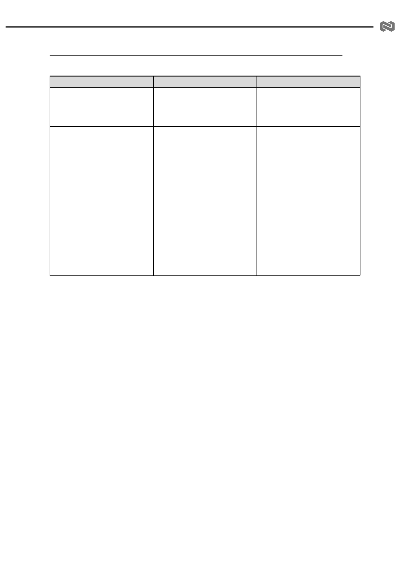
Troubleshooting
Problems
Causes
Solutions
No Power / All LED off
Power supply not connected,
connected fully, or wrong power
supply.
Check if the power supply is
connected correctly and the
output voltage value is within
recommended specifications.
No sound or sound issues
The HDMI connection is faulty,
the audio format is not
supported by the displays, or
the source player is set to
another port for audio output
Check if the HDMI cables are
connected correctly.
Check if the audio format is
supported by the display and
that a user has not changed the
supported audio format on the
player`s audio output. Ensure
output settings from the HDMI
source device as set correctly.
No picture or picture flickers
The HDMI cable may be faulty
or the category cable quality is
faulty.
Check if the HDMI
and category cable connections
are correct and undamaged.
Change to another good
working HDMI cable or category
cable (CAT6 or better cable is
recommended).
Address: 830 National Drive #140, Sacramento, CA 95834, USA · Tel: +1(888)499-9906 · Email: support@bzbgear.com 37

BZBGEAR BG-IPGEAR-ULTRA PRODUCT MANUAL
Tech Support
Have technical questions? We may have answered them already!
Please visit BZBGEAR’s support page (bzbgear.com/support) for helpful information and
tips regarding our products. Here you will find our Knowledge Base
(bzbgear.com/knowledge-base) with detailed tutorials, quick start guides, and step-by-step
troubleshooting instructions. Or explore our YouTube channel, BZB TV
(youtube.com/c/BZBTVchannel), for help setting up, configuring, and other helpful how-to
videos about our gear.
Need more in-depth support? Connect with one of our technical specialists directly:
Phone
1.888.499.9906
Email
support@bzbgear.com
Live Chat
bzbgear.com
Limited Product Warranty Terms
Pro Line: 5-year warranty from the date of purchase for AV/Broadcasting products bought
on or after August 1, 2024.
Essential Line: 3-year warranty from the date of purchase for AV/Broadcasting products
bought on or after August 1, 2024.
Cables: Lifetime Limited Product Warranty.
For complete warranty information, please visit bzbgear.com/warranty.
For questions, please call 1.888.499.9906 or email support@bzbgear.com.
Mission Statement
BZBGEAR is a breakthrough manufacturer of high-quality, innovative audiovisual equipment
ranging from AVoIP, professional broadcasting, conferencing, home theater, to live
streaming solutions. We pride ourselves on unparalleled customer support and services.
Our team offers system design consultation, and highly reviewed technical support for all
the products in our catalog. BZBGEAR delivers quality products designed with users in
mind.
Copyright
All the contents in this manual and its copyright are owned by BZBGEAR. No one is allowed
to imitate, copy, or translate this manual without BZBGEAR’s permission. This manual
contains no guarantee, standpoint expression or other implies in any form. Product
specification and information in this manual is for reference only and subject to change
without notice.
All rights reserved. No reproducing is allowed without acknowledgement.
Address: 830 National Drive #140, Sacramento, CA 95834, USA · Tel: +1(888)499-9906 · Email: support@bzbgear.com 38