
1
IMPORTANT SAFETY INSTRUCTIONS
When using this product, basic precautions should always be followed, including the following:
Read all instructions before using this equipment.
WARNING – To reduce the risk of burns, fire, or injury to persons:
1. Please assemble in strict accordance with the instructions.
2. The product is only for indoor use. Please avoid long-term exposure to humid environments.
3. The installation parts need to be placed on a mat (rubber or wood) to avoid getting dirty.
4. During the assembly, align all bolts with the corresponding pre-drilled holes and tighten one by one.
5. Ensure that all nuts and bolts are tightened before use.
6. To ensure the safety of users, please check whether all bolts and other connecting parts are locked
before each use.
7. Check the screws regularly. Long-term use may cause screws to loosen. Retighten if necessary to
ensure stability and safety.
8. Do not use corrosive detergent to clean table.
9. Children are not allowed to assemble the product. During the assembly, please place all parts out of
the reach of children.
10. Do not allow children to stand, climb or play with the product to avoid serious personal injury.
11. Keep plastic bags out of reach of children to avoid choking and other potential hazards.
SAVE THESE INSTRUCTIONS

2
IMPORTANT SAFETY INFORMATION
We thank you for choosing our product. To ensure your safety and health, please use this equipment
correctly. It is important to read this entire manual before assembling and using. Safe and effective use
can only be achieved if the equipment is assembled, maintained and used properly. It is your
responsibility to ensure that all users of the equipment are informed of all warnings and precautions.
1. Use the equipment on a solid, flat level surface with a protective cover for your floor or carpet.
2. Ensure that all nuts and bolts are tightened securely before using. The safety of the equipment can
only be maintained if it is regularly examined for damage and/or wear and tear.
3. Always use the equipment as indicated. If you find any defective components while assembling,
checking the equipment, or if you hear any unusual noises coming from the equipment during using,
discontinue use of the equipment immediately and do not use until the problem has been rectified.
4. Do not place fingers or objects into the moving parts of the equipment.
5. The static maximum weight capacity of this unit is 187 lbs (85 kgs). Lift stroke is 29.5 inch-47.2 inch
(750mm-1200mm).
6. Your product is intended for use in cool and dry conditions. You should avoid storage in extreme
cold, hot, or damp areas as this may lead to corrosion and other related problems.
7. This equipment is designed for indoor and home use only.
3
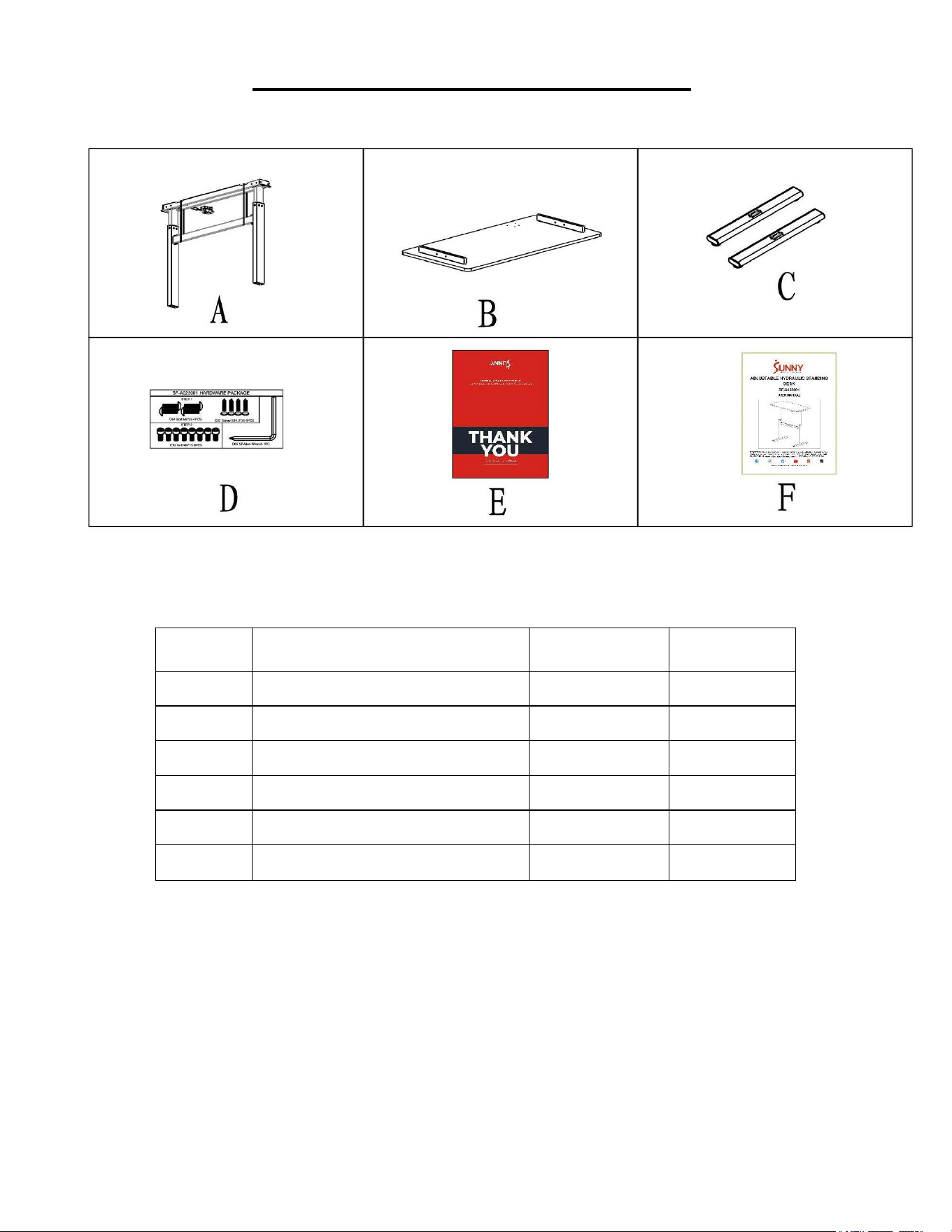
PRE-ASSEMBLY CHECK LIST
Before you start to assemble, please make sure all parts are included.
No.
Description
Spec.
Qty.
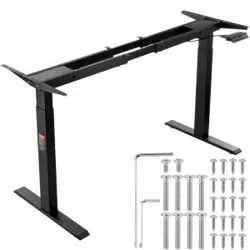
A
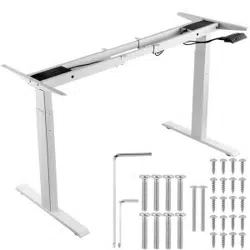
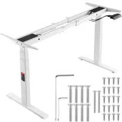
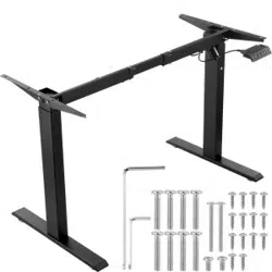
Main Frame
1
B
Table Board Set
1
C
Foot Tube Set
2
D
Hardware Package
1
E
THANK YOU Card
1
F
Manual
1
4
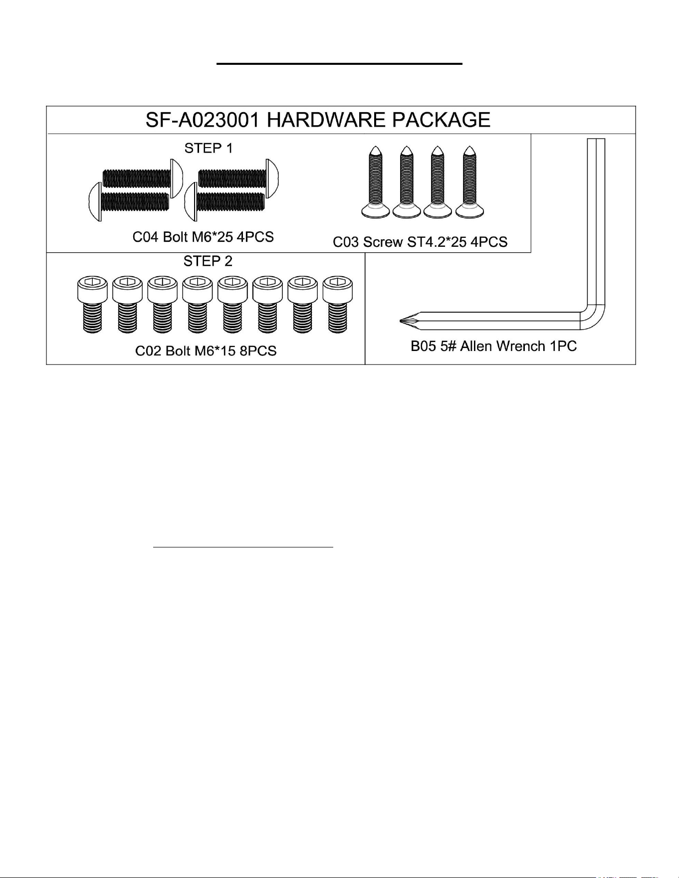
HARDWARE PACKAGE
Ordering Replacement Parts (U.S. and Canadian Customers only)
Please provide the following information in order for us to accurately identify the part(s) needed:
The model number (found on cover of manual)
The product name (found on cover of manual)
The part number found on the “EXPLODED DIAGRAM” and “PARTS LIST” (found near the end of the
manual)
Please contact us at support@sunnyhealthfitness.com or 1-877-90SUNNY (877-907-8669).
5
ASSEMBLY INSTRUCTIONS
We value your experience using Sunny Health and Fitness products. For assistance with parts or
troubleshooting, please contact us at support@sunnyhealthfitness.com or 1-877-90SUNNY
(877-907-8669).
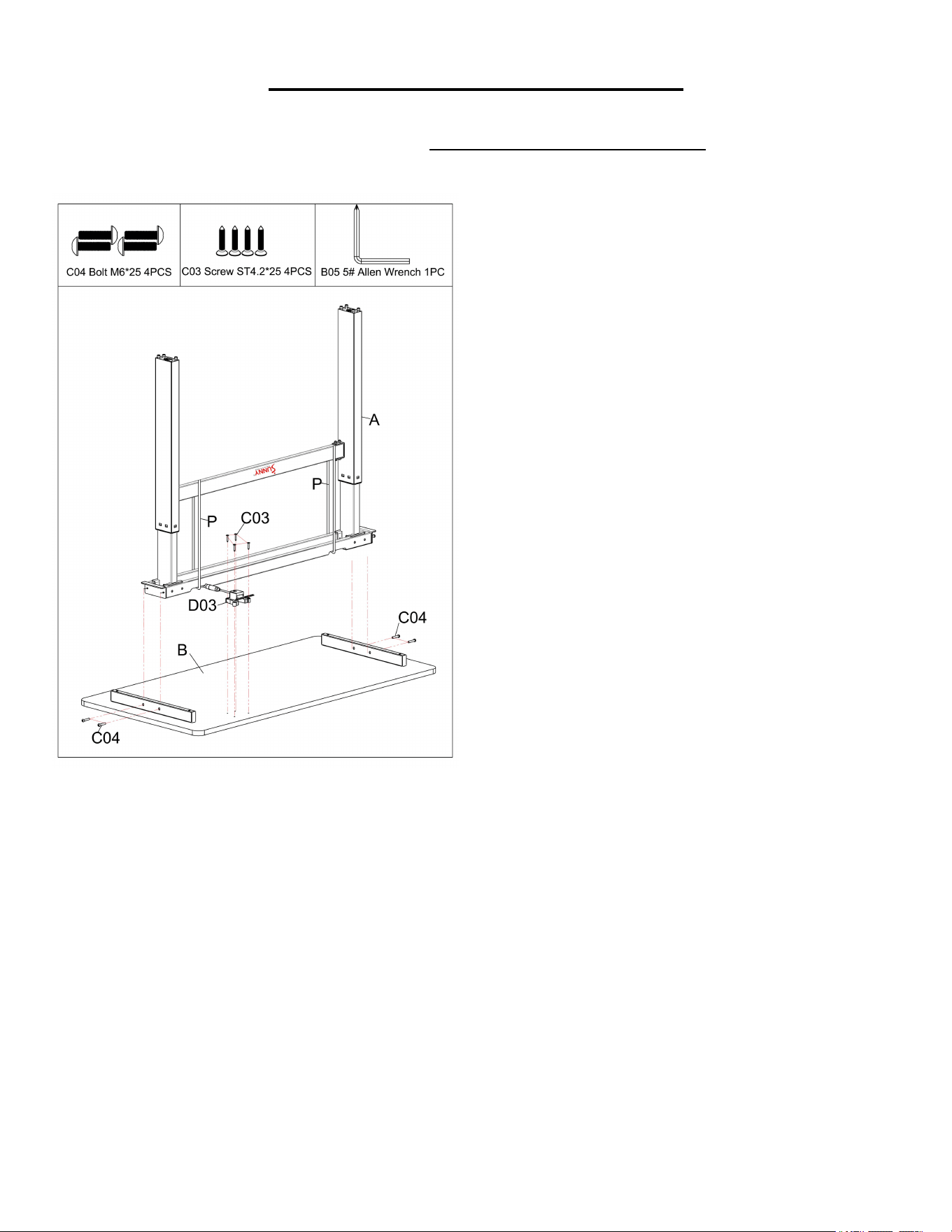
STEP 1:
Open the carton and remove contents.
NOTE: DO NOT cut the 2 Packing Belts
(No. P) on Main Frame (No. A).
Place the Table Board Set (No. B) down
on level ground, ensure that you have a
work area that is clean and has adequate
space.
There is a “Sunny” logo marked on the
Main Frame (No. A). Please ensure the
logo is facing the Wrench Bracket (No.
D03).
Attach the Main Frame (No. A) to the
Table Board Set (No. B) by using 4 Bolts
(No. C04). Tighten and secure with 5#
Allen Wrench (No. B05).
Attach the Wrench Bracket (No. D03) to
the Table Board Set (No. B) by using 4
Screws (No. C03). Tighten and secure with
5# Allen Wrench (No. B05).
6
We value your experience using Sunny Health and Fitness products. For assistance with parts or
troubleshooting, please contact us at support@sunnyhealthfitness.com or 1-877-90SUNNY
(877-907-8669).
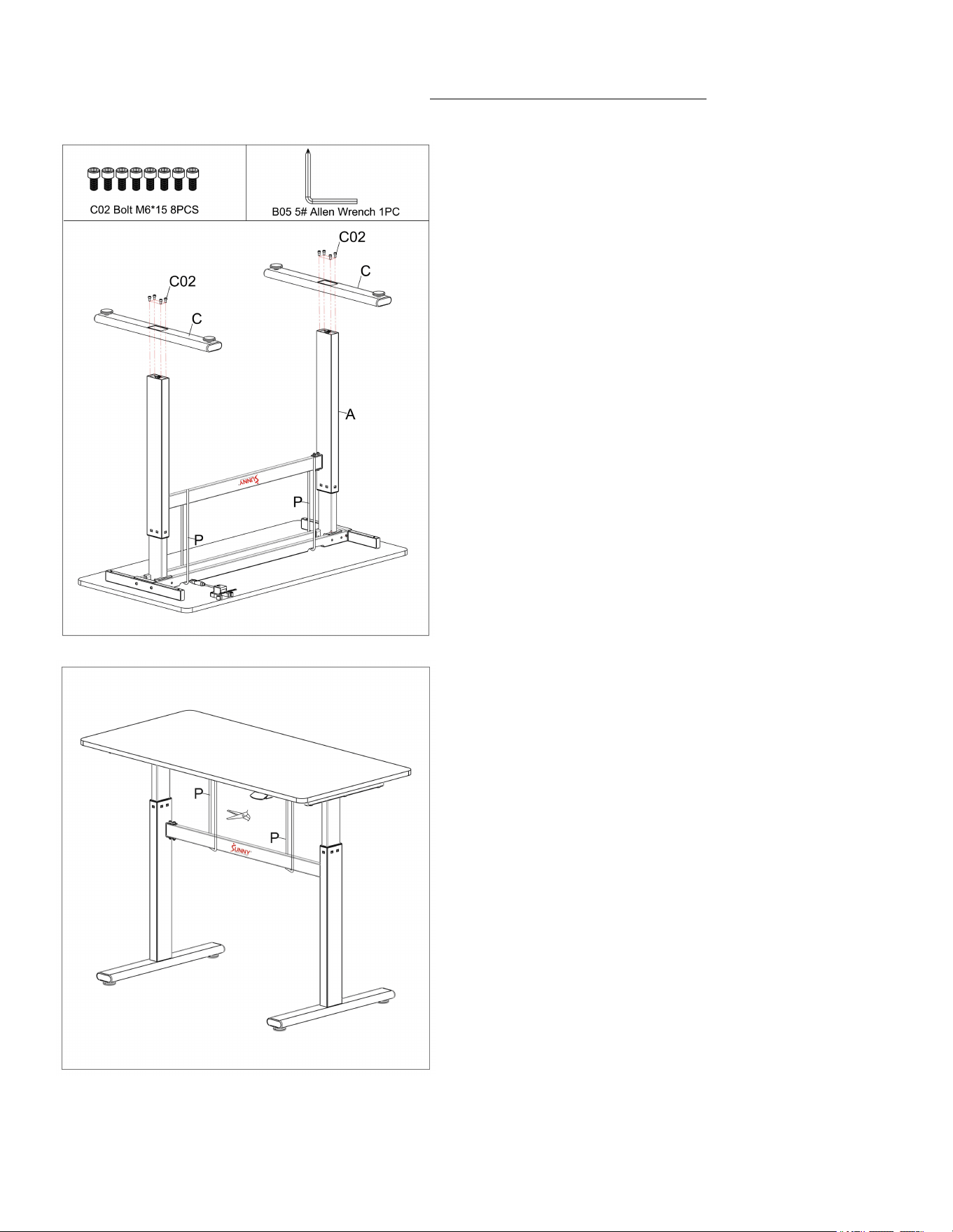
STEP 2:
Attach the 2 Foot Tube Sets (No. C) to the
Main Frame (No. A) by using 8 Bolts (No.
C02). Tighten with 5# Allen Wrench (No.
B05).
STEP 3:
Turn the desk right side up.
You may now cut the 2 Packing Belts (No.
P) and discard.
The assembly is completed!
7
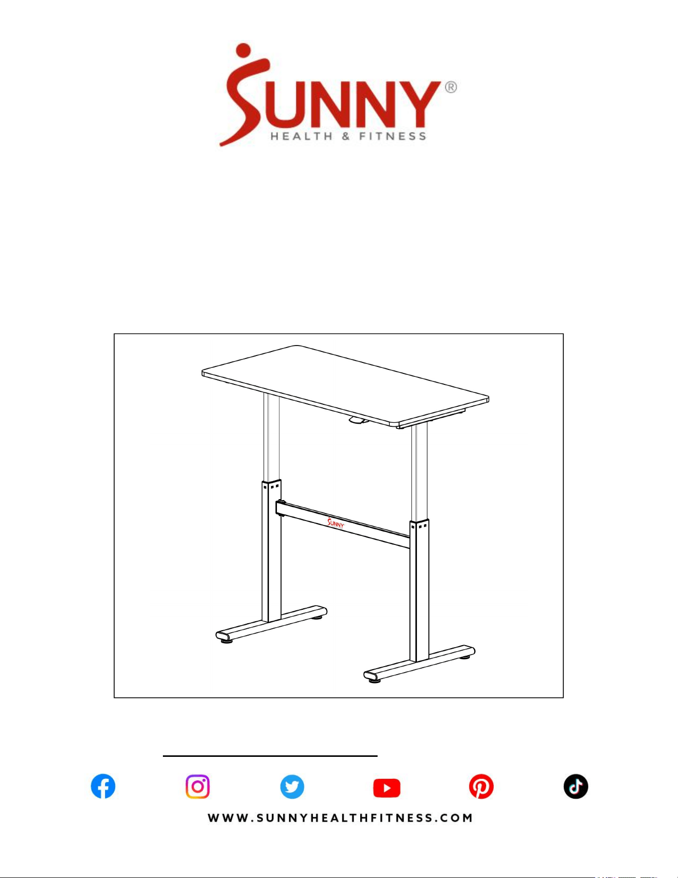
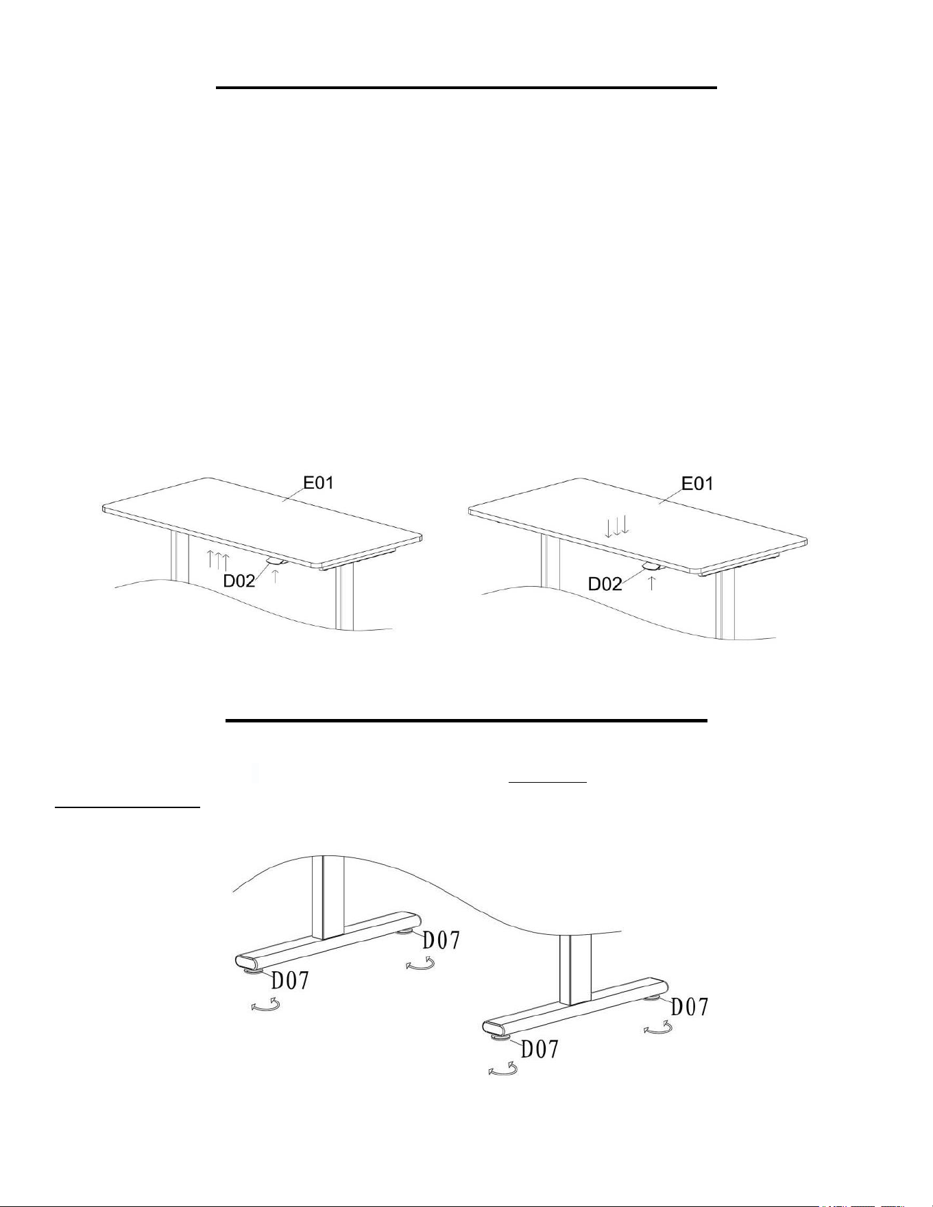
HOW TO ADJUST THE DIRECTION
How to Raise the Table Board
Move the Lifting Wrench (No. D02) upward with your right hand and hold it. Then use your left hand
to lift the Table Board (No. E01), the Table Board (No. E01) will rise. To stop the Table Board (No.
E01) from rising, release the Lifting Wrench (No. D02). The maximum height the Table Board (No.
E01) can rise to is 47.2 inch. Based on that, you can choose any height you feel comfortable with.
How to Press Down the Table Board
Move the Lifting Wrench (No. D02) upward with your right hand and hold it. Then press down slightly
left hand at the center of the Table Board (No. E01), the Table Board (No. E01) will begin to drop
down. To stop the Table Board (No. E01) from dropping down, release the Lifting Wrench (No. D02).
The minimum height of desktop can drop down to is 29.5 inch.
HOW TO ADJUST THE BALANCE
If you find that the lift table is unbalanced, you can adjust the balance by using the 4 Pad Adjustments
(No. D07). Adjust the 4 Pad Adjustments (No. D07) clockwise to raise the height of footpad, and
counter-clockwise to lower the height of footpad.
8
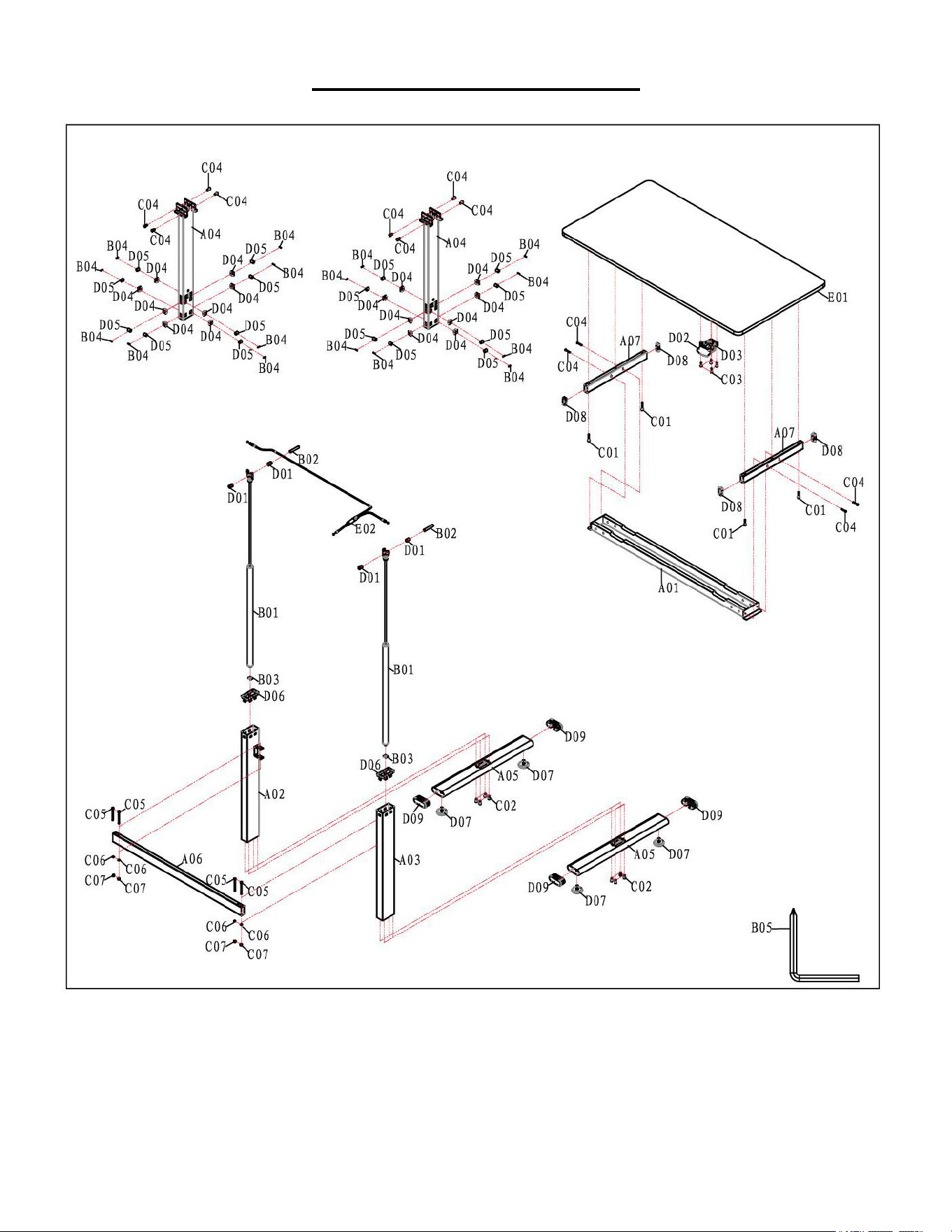
EXPLODED DIAGRAM
9
PARTS LIST
Version 1.0
No.
Description
Specification
Qty.
No.
Description
Specification
Qty.
A01
Table Bracket
1
C04
Bolt
M6*25
12
A02
Left Outer Upright Tube
1
C05
Bolt
M6*70
4
A03
Right Outer Upright Tube
1
C06
Washer
6
4
A04
Inner Upright Tube
2
C07
Lock Nut
M6
4
A05
Foot Tube
2
D01
Sleeve
4
A06
Connection Tube
1
D02
Lifting Wrench
1
A07
Table Rack Cross Tube
2
D03
Wrench Bracket
1
B01
Gas Spring
2
D04
Roller Frame
16
B02
Gas Spring Fixed Shaft
2
D05
Roller
16
B03
Gas Spring Stuck Piece
2
D06
Slide Bushing
2
B04
Roller Shaft
16
D07
Pad Adjustment
4
B05
5# Allen Wrench
1
D08
Rectangular Plug
4
C01
Bolt
M6*50
4
D09
Oval Plug
4
C02
Bolt
M6*15
8
E01
Table Board
1
C03
Screw
ST4.2*25
4
E02
Wire Rope
1