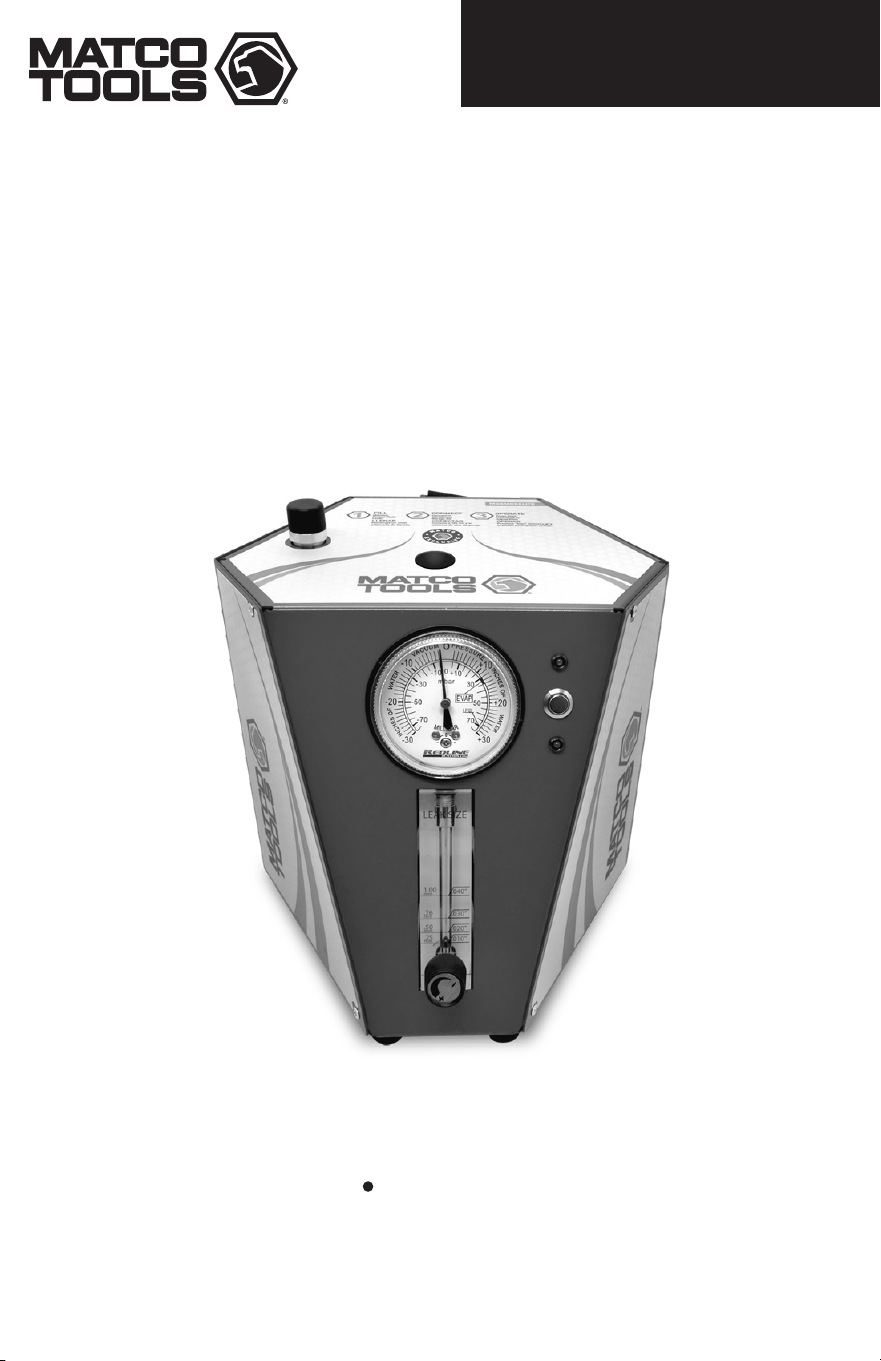
MDSMOKELITE
Operating Instructions Important Safety Instructions
DIAGNOSTIC LEAK LOCATOR

Specifications &
Application Guide....................................................................................................... 1
Safety....................................................................................................................... 2
Components............................................................................................................. 3
Accessories ............................................................................................................ 4
Set up...................................................................................................................... 6
Testing for Leaks........................................................................................................ 7
How to Diagnose Leaks:
Intake System / Vacuum Leaks................................................................................ 8
EVAP - Fuel Vapor Recovery
System Leaks........................................................................................................ 9
Exhaust System Leaks........................................................................................... 10
Under Dashboard Leaks......................................................................................... 10
Troubleshooting.......................................................................................................... 11
Maintenance.............................................................................................................. 12
Warranty ................................................................................................................. 13
Spanish......................................................................................................................14
IMPORTANT SAFETY INSTRUCTIONS
MDSMOKELITE
L x W x H 9 in. x 8.75 in. x 8.5 in. (23 cm x 22 cm x 21 cm)
Weight 8.6 lbs. (3.9 kg)
Shipping Weight 14.3 lbs. (6.4 kg)
Power Supply 12 Volts DC
Power Consumption 12A MAX
Output Pressure 0.5 PSI / 13.0 in. H
2
0 / 0.032 BAR
Operating Temperature 32°F - 122°F (0°C - 50°C)
Operating Humidity No Restrictions
Operating Altitude No Restrictions
Vapor Output Hose 10 ft. (3.1 m)
Power Supply Cables 10 ft. (3.1 m)
Operating Modes Vapor Cycle / Air Only Cycle
Pressure Supply Compressed Air
Housing Material Steel
Vapor Chamber Material Billet Aluminum
Vapor Chamber Assembly Bolted
SPECIFICATIONS
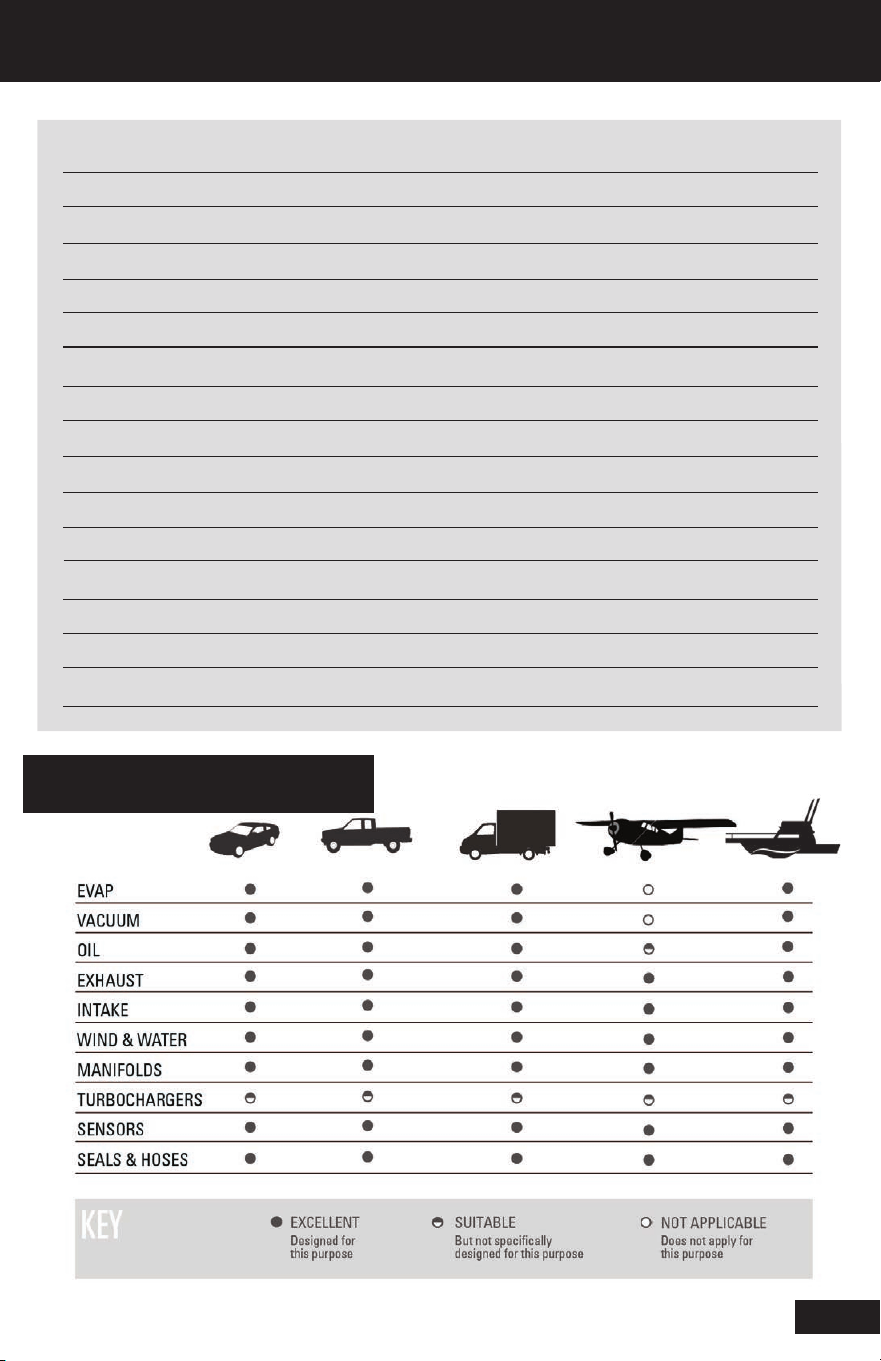
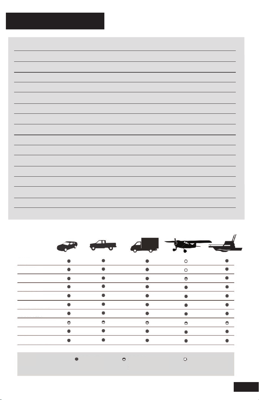
APPLICATION GUIDE
LEAKS
*
1

MDSMOKELITE
2
SAFETY
The procedures in this operation manual are intended to be basic guidelines for users to
practice using this equipment
IMPORTANT SAFETY INSTRUCTIONS
When using your garage equipment, basic safety precautions should always be followed,
including the following:
1. Read all instructions.
2. Care must be taken as burns can occur from touching hot parts.
3. Do not operate equipment with a damaged cord or if the equipment has been dropped
or damaged – until it has been examined by a qualified service person.
4. Do not let a cord hang over the edge of the table, bench, or counter or come in contact
with hot manifolds or moving fan blades.
5. Let equipment cool completely before putting away. Loop cord loosely around equipment
when storing.
6. To reduce the risk of fire, do not operate equipment in the vicinity of open containers of
flammable liquids (gasoline).
7. Adequate ventilation should be provided when working on operating internal combustion
engines.
8. Keep hair, loose clothing, fingers, and all parts of body away from moving parts.
9. To reduce the risk of electric shock, do not use on wet surfaces or expose to rain.
10. Use only as described in this manual. Use only manufacturer’s recommended
attachments.
11. ALWAYS WEAR SAFETY GLASSES. Everyday eyeglasses only have impact resistant
lenses, they are not safety glasses.
SAVE THESE INSTRUCTIONS
SAFETY PRECAUTIONS
• All diagnostic work should be performed with the engine off
• Do not leave a vehicle unattended while equipment is connected
or operating
• Do not perform tests near a source of spark of ignition
• When working with the fuel system, work in a well-ventilated area
• Always wear the appropriate safety protection
Wear OSHA standard eye wear and protective gloves when using
this equipment
WARRANTY
For detailed product warranty information refer to the Limited Warranty statement
document included with the product.
MDSMOKELITE
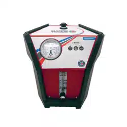
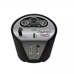
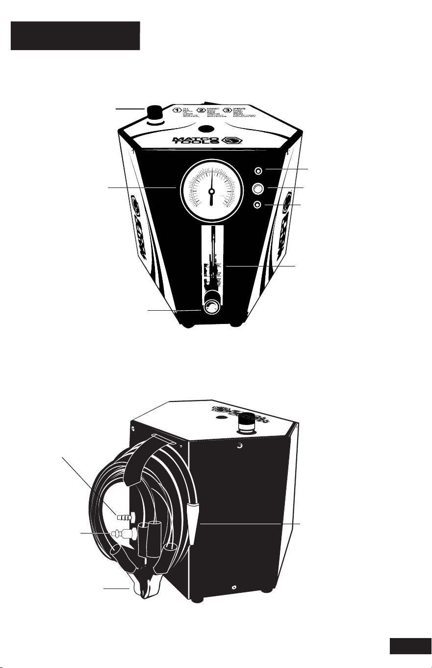
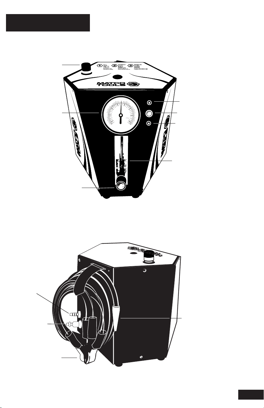
COMPONENTS
3
Vapor
Output
Hose/Nozzle
Air
Inlet
Battery
Power
Cables
Power
Indicator
Compound
Pressure Gauge
On/Off
Switch
Vapor
Indicator
I
N
C
H
E
S
O
F
W
A
T
E
R
V
A
C
U
U
M
P
R
E
S
S
U
R
E
I
N
C
H
E
S
O
F
W
A
T
E
R
1 PSI
7
0
-10
-20
+30
+20
-7 kPa
-5
-3
-1
+1
3
5
-30
Fluid
Fill Dipstick
Flow
Control
Knob
Flow Meter
Barbed hose
fitting
MDSMOKELITE
4
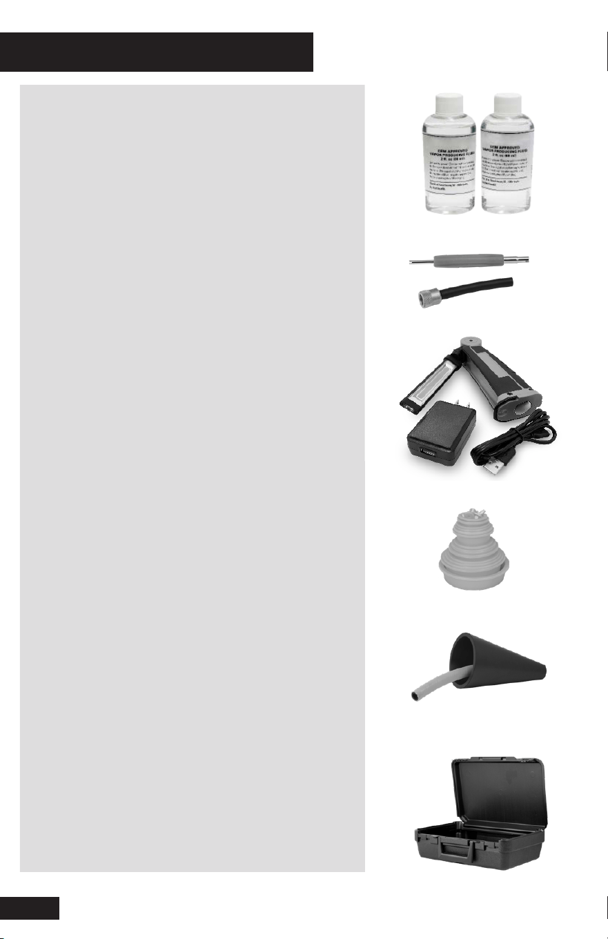
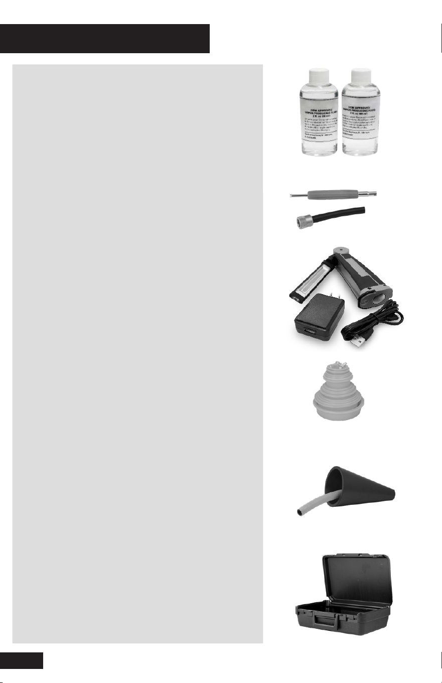
OEM-Approved Vapor Producing Fluid
[PN 96-0074]
Vapor Producing Fluid will perform over
500+ typical tests per bottle
IMPORTANT: Contains NO Dye / Contaminants
EVAP Service Tool Kit [PN 96-0003]
Schrader Valve Removal Tool
EVAP Service Port Adaptor
Daylight Spectrum LED Cordless Light
[PN 96-0185]
Bright white beam finds even the tiniest
wisps of vapor under the hood or chassis
Cap Plug Kit [PN 96-0007]
Seals a variety of openings in order to
pressurize system for testing
Standard Cone Adaptor [PN 96-0004]
For use to seal openings from 1 in. (2.5 cm) to
3.4 in. (8.6 cm) to introduce vapor into ex-
haust and induction systems
Accessory Storage Case [PN 91-0011]
ACCESSORIES INCLUDED
MDSMOKELITE
5
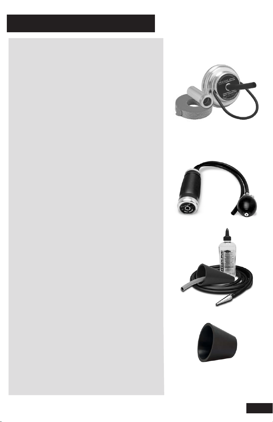
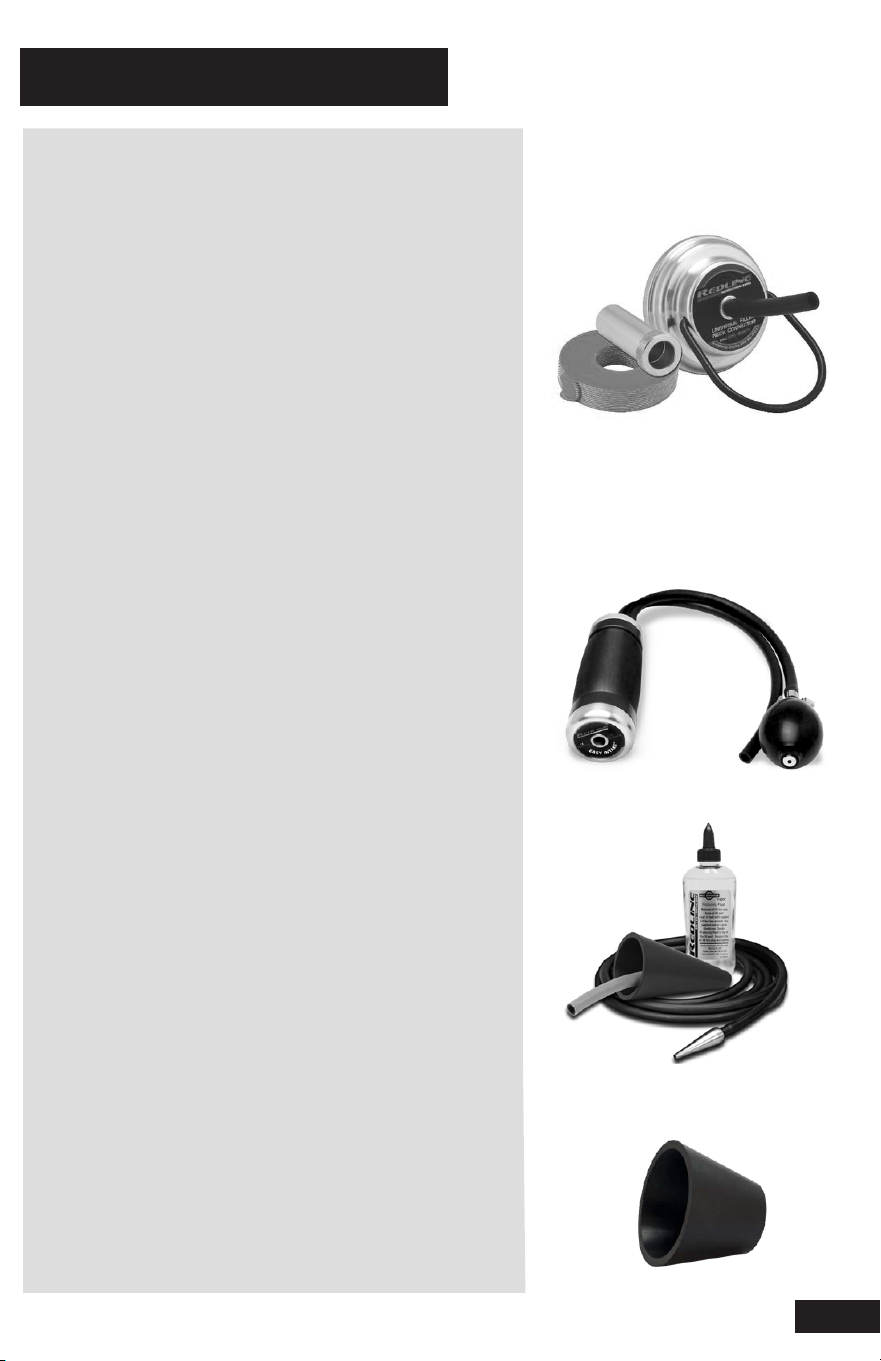
OPTIONAL ACCESSORIES
Easy EVAP
™
[PN SMOKE30]
This universal Fuel Filler Neck Connector
system fits 100% of vehicles to simplify
EVAP testing
Universal Filler Neck Connector [PN 95-0011]
Made in USA of billet aluminum
Sealing Disks [PN 96-0017]
Creates an air-tight seal with any filler neck
CapAdapt
™
Capless Adaptor [PN 96-0054]
Opens throat of capless filler necks
Easy INTAKE
™
[PN EZINT95]
Award-winning Easy INTAKE
™
is an inflatable
block off bladder with a pressurized vapor
pass-through that allows technicians to test
an entire intake or exhaust system quickly
and easily.
Extended Accessory Kit [PN 95-0005]
Standard Cone Adaptor for dual exhaust
For use to seal openings between 1 in. (2.5 cm)
to 3 in. (7.6 cm)
Vapor Output Hose extension allows operator
to test 20 ft. (6.1 m) from unit
Additional OEM-Approved vapor producing
fluid for 500+ typical tests
XL Cone Adaptor [PN 16-0003]
For use to seal openings from 3.4 in. (8.6 cm)
to 5.25 in. (13.3 cm) to introduce vapor into
exhaust and induction systems
MDSMOKELITE
6
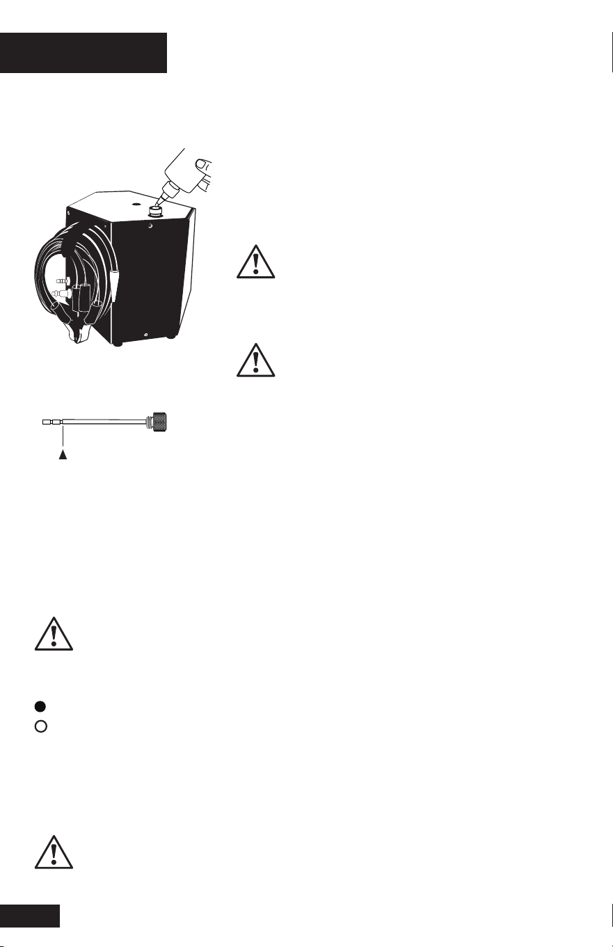
SET UP
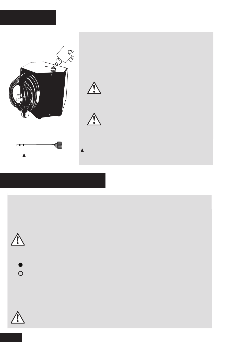
1. FILL / ADD VAPOR PRODUCING FLUID
Remove Fluid Fill Dipstick. Pour Vapor Producing Fluid
into Fluid Fill Port until fluid level is near top of the fill
line on the Dipstick. Replace Fluid Fill Dipstick
Do not overfill
First time fill requires approx. 2 oz (60 ml)
Check fluid level every 50-100 tests
Never use dyes, solvents or other contaminants
intake or exhaust systems beca use they may
coat and/or harm critical sensors, catalysts
Fill Fluid to Maximum Fill Line on Dipstick
HOOK UP CONNECTIONS
2. CONNECT TO POWER
This machine runs on a fully-charged 12-Volt battery
Connect red lead (+) to battery’s positive terminal
Connect black lead (-) to chassis ground
Do not connect to battery charger or jumper box
Max voltage 12V DC
POWER INDICATOR:
Green Light: Machine has adequate power
No Light: No Power, See Troubleshooting Section
3. CONNECT TO AIR SUPPLY
Connect Air Input Hose to a compressed air supply
If necessary, replace Air Fitting to match your air supply
Max inlet pressure 150 PSI

MDSMOKELITE
TESTING FOR LEAKS
4. PUSH ON / OFF SWITCH
Begins 5-minute vapor cycle
VAPOR INDICATOR:
Amber Light: Vapor is Generating
Flashing Amber Light: Open Circuit, See Troubleshooting Section
No Amber Light: No Vapor Generating
Turn Flow Control Knob counter-clockwise to release vapor/pressure
Flow Meter indicates flow and measures leak size
Use provided Inspection Light to locate leaks
Perform repair(s) as needed
VERIFY REPAIRS
5. PERFORM DECAY / LEAK DOWN TEST
Pressurize the sealed system
Lock out system by turning Flow Control Knob clockwise to the fully closed position
OBSERVE PRESSURE GAUGE FOR DECAY:
Pressure Holds: No leaks, Repair is complete
Pressure Decreases:
Leak(s) exist, Repeat Steps 4 & 5 until all repairs are complete
NOTE: Not all systems are designed to be 100% sealed
7

MDSMOKELITE
8
HOW TO DIAGNOSE INTAKE SYSTEM & VACUUM LEAKS
This procedure will locate leaks in vacuum lines as well as manifolds, EGR valves,
oil seals, gaskets, solenoids, o-rings, ducting, throttle shafts, diaphragms,
canisters, and more.
For best results, test in a draft-free area
1. Remove the air filter housing from ducting
2. If the vehicle has a round inlet tube from the air filter, place the EZINT95
Adaptor
into the duct toward the engine
3. Put Vapor Supply Hose into Adaptor to introduce vapor into the
system
4. Use provided Inspection Light to locate leaks
ALTERNATIVE METHOD
1. Select an appropriate vacuum line to access the vacuum system
(i.e. a brake booster supply line before the check valve)
2. Seal all system openings
a. Air Intake must be sealed to prevent vapor from leaking back through
the intake
b. To seal the intake, use Cap Plugs, a latex glove, or plastic wrap around the
filter
3. Put Vapor Output Hose into Adaptor to introduce vapor into the system
4. Use provided Inspection Light to locate leaks

MDSMOKELITE
HOW TO DIAGNOSE EVAP LEAKS
Leaks in the EVAP system, or fuel vapor recovery system, are frequently the
cause of check engine lights. Using a diagnostic leak detector, these leaks can be
quickly diagnosed and repaired, making them profitable services for repair facilities
PRESSURE DECAY / LEAK DOWN TEST
1. Verify if a leak is currently present, test the EVAP system using the Decay or
Leak Down testing method with air only
a. To access the EVAP service port, remove the green cap
Remove Schrader valve using the provided Schrader Valve Removal Tool
(Schrader valve has left-handed threads, turn clockwise to remove)
b. Using a scan tool, close the vent solenoid to close EVAP system from
atmosphere (If vent solenoid does not close, intermittent solenoid may have
failed)
c. Input air into EVAP system until fully pressurized. When pressure gauge
reaches its maximum pressure (12-14 inches of water column), Flow Meter
will indicate leak size (if leak is present)
d. Lock out system by turning the Flow Control Knob to the fully closed position.
Observe pressure gauge for decay
e. If no leaks are present, system will hold pressure
f. If pressure decays or leaks down, leaks exist. Proceed to step 2 to find leaks
2. Push ON / OFF button to begin 5 minute vapor cycle
3. Remove the fuel cap
4. Open Flow Control Valve to input vapor into the system through adaptor
5. Replace fuel cap when dense vapor is seen exiting the filler neck
6. Continue pumping vapor into the system
7. Using the provided Inspection Light, inspect for leaks (under the hood
and tracing the route of the EVAP system on the underside of the vehicle)
8. Repair the system as needed
9. Repeat procedures in steps above until all repairs are complete and final quality
test is performed, indicating no leaks
9

MDSMOKELITE
10
HOW TO DIAGNOSE EXHAUST LEAKS
HOW TO DIAGNOSE UNDER DASHBOARD LEAKS
This test is most effective when exhaust system is cold
Thermal expansion may cause small leaks to seal
1. Insert appropriate Adaptor into the end of the tailpipe
If the vehicle has dual exhaust with cross over system, plug the other
tailpipe to seal the system
2. Put Vapor Output Hose into Adaptor to introduce vapor into
the system
A hot catalytic converter may consume some of the vapor
All testing is performed with the engine off
Many vehicles have a common vacuum line, leading from the engine
compartment through the fire wall, under the dashboard
This line supplies vacuum to climate control functions and other vacuum-
operated systems
1. Disconnect the vacuum line under the hood at its source
2. Input vapor into the vacuum line
3. Observe the Flow Meter and Pressure Gauge while changing the climate
controls from heat to vent, to defrost, etc.
4. Change in the Flow Meter or Pressure Gauge’s reading will indicate which
system is leaking
5. Set the climate control to the leaking system
6. Use provided Inspection Light to locate under dash leaks
Central locking system leak inspection is performed in the same manner
Activate control solenoids while introducing vapor into the system

MDSMOKELITE
TROUBLESHOOTING
PROBLEM SOLUTION
Check polarity
No Green Light Ensure 12-Volt battery is fully-charged
Reconnect power cables
Ensure 12-Volt battery is fully-charged
Amber Light Flashing Open circuit / internal component
Contact Technical Support
Check connection to compressed air
No Air Flow Open the flow control valve
Check hoses are not kinked
Check Fluid Level
Not Enough Visable Vapor Open the flow control valve
Check hoses are not kinked
Flow Meter Clean Flow Meter
Ball Sticking
Gauge Bouncing Drain Vapor Hose
Flow Meter Bouncing
11
MDSMOKELITE
12
MACHINE MAINTENANCE
CHECK FLUID LEVEL See Set Up (pg 6)
Remove dipstick
Pour OEM-Approved Vapor Producing Fluid into Fluid Fill Port until fluid level
reaches top line of Dipstick
Replace Dipstick
Check fluid level every 50 - 100 tests
Do not overfill
CLEAN FLOW METER
Disconnect air supply and power from the machine
Remove Flow Valve with 12mm Wrench
Tilt machine forward to drain flowmeter of residue fluid
Reinstal flow valve
Do not use alcohol / cleaners on flow meter
DRAIN VAPOR HOSE
Elevate the machine
Allow the entire vapor hose to hang downward
Place a container beneath the nozzle to capture fluid
Process takes approximately 5 minutes

MDSMOKELITE
WARRANTY
The manufacturer, Redline Detection, LLC. (“Redline”) warrants this
product to be free from defects in workmanship and material under
normal use and service for a period of two years from the date
of purchase. Redline’s liability under this warranty is limited to:
(1) repair or replacement of any parts or product which are
determined to be defective; or at Redline’s sole option
(2) refund of the purchase price. In either event, product to be returned
shipping prepaid within the one year warranty period. Additionally, the vapor
chamber in any Redline product has a lifetime warranty as to its structural
integrity: Any Redline-manufactured vapor chamber that leaks, cracks, or
separates in any way shall be repaired / replaced by Redline at no charge.
Products are only to be used by persons having skill and knowledge in the
automotive repair field, and improper use or maintenance may cause serious
injury. In no event shall Redline be liable beyond replacement of product
or refund of the purchase price. This warranty shall void if a product is
improperly maintained, altered, abused or otherwise misused in any way.
THE AFORESAID WARRANTY IS IN LIEU OF ALL OTHER WARRANTIES,
AND THERE ARE NO OTHER WARRANTIES OR REPRESENTATIONS
OF ANY KIND WHATSOEVER MADE BY REDLINE, EITHER EXPRESSED
OR IMPLIED, INCLUDING BUT NOT LIMITED TO, ANY IMPLIED
WARRANTY OF MERCHANTABILITY OR FITNESS FOR A PARTICULAR USE
OR APPLICATION.
THE PURCHASER’S SOLE REMEDY FOR ANY DEFECTIVE PRODUCT SHALL BE
REPAIR, REPLACEMENT OR REFUND AS STATED ABOVE AND REDLINE SHALL
NOT BE LIABLE TO ANYONE FOR ANY SPECIAL, CONSEQUENTIAL, INCIDENTAL,
INDIRECT OR PUNITIVE DAMAGES ON ACCOUNT OF DEFECTIVE PRODUCTS,
HOWEVER CAUSED, UNDER ANY THEORY OF LIABILITY.
13

Made in USA
to Matco specifications
Matco Tools
Stow, Ohio 44224
1810322-19
Tech Support
866-289-8665
MDSMOKELITE
Instrucciones de Operación Instrucciones Importantes de Seguridad
DETECTOR DE FUGAS DE DIAGNÓSTICO

MDSMOKELITE
SPANISH
Presupuesto....................................................................................................... 15
Instrucciones de Seguridad.................................................................................. 16
Componentes..................................................................................................... 17
Accessorios Incluidos.......................................................................................... 18
Accessorios Opcionales....................................................................................... 19
Preparar............................................................................................................ 20
Pruebas De Fugas.............................................................................................. 21
Como Diagnostir El Sistema De Toma Y Fugas De Vacio.......................................... 22
Como Diagnostir Las Fugas De EVAP.................................................................... 23
Como Diagnostir Las Fugas De Escape................................................................. 24
Solución De Problems.......................................................................................... 25
Mantener........................................................................................................... 26
Garantía............................................................................................................ 27
14
INFORMACIÓN IMPORTANTE DE SEGURIDAD
MDSMOKELITE
PRESUPUESTO
GUIA DE APLICACION
FUGAS
*
Excelente
diseñado para este
propósito
Adecuado
Pero no específicamente
diseñado para este propósito
No aplica
No aplica para este
propósito.
EVAP
Vacío
petróleo
escape
consumo
viento y agua
colectores
turbocompresores
sensores
sellos y mangueras
LLAVE
SPANISH
15
L x W x H 9 in. x 8.75 in. x 8.5 in. (23 cm x 22 cm x 21 cm)
Peso 8.6 lbs. (3.9 kg)
Peso de envío 14.3 lbs. (6.4 kg)
Fuente de alimentación 12 voltios DC
Consumo de energía 12A MAX
Protección contra sobrecorriente 12A Restablecer el disyuntor
Presión de salida 0.5 PSI / 13.0 in. H20 / 0.032 BAR
Temperatura de funcionamiento de 32 ° F a 122 ° F (0 ° C a 50 ° C)
Humedad de funcionamiento sin restricciones
Altitud de operación sin restricciones
Manguera de salida de vapor 10 pies (3.1 m)
Cables de fuente de alimentación 10 pies (3.1 m)
Modos de funcionamiento Ciclo de vapor / Ciclo de aire solamente
Presión de suministro de aire comprimido
Material de la carcasa Acero / ABS
Material de la cámara de vapor Billet Aluminio
Asamblea de la cámara de vapor atornillada
MDSMOKELITE
INSTRUCCIONES DE SEGURIDAD
Los procedimientos en este manual de operación pretenden ser pautas básicas para que los
usuarios practiquen el uso de este MDSmokeLite
INSTRUCCIONES DE SEGURIDAD IMPORTANTES
Cuando utilice el equipo de su garaje, siempre se deben seguir las precauciones de seguridad
básicas, incluidas las siguiendo:
1. Lea todas las instrucciones.
2. Se debe tener cuidado ya que pueden ocurrir quemaduras al tocar las partes calientes.
3. No opere el equipo con un cable dañado o si el equipo se ha caído o
dañado - hasta que haya sido examinado por una persona de servicio calificada.
4. No deje que un cable cuelgue del borde de la mesa, banco o mostrador o entre en contacto
con Colectores calientes o álabes móviles.
5. Deje que el equipo se enfríe completamente antes de guardar. Cable de bucle suelto
alrededor del equipo cuando se almacena.
6. Para reducir el riesgo de incendio, no opere equipos cerca de recipientes abiertos de
Líquidos inflamables (gasolina).
7. Se debe proporcionar una ventilación adecuada cuando se trabaje en operar motores de
combustión interna.
8. Mantenga el cabello, la ropa suelta, los dedos y todas las partes del cuerpo alejadas de las
partes móviles.
9. Para reducir el riesgo de descarga eléctrica, no lo utilice sobre superficies mojadas ni lo
exponga a la lluvia.
10. Use solo como se describe en este manual. Use solo los accesorios recomendados por el
fabricante.
11. SIEMPRE UTILICE GAFAS DE SEGURIDAD. Las gafas de uso diario solo tienen resistencia
al impacto. Lentes, no son gafas de seguridad.
GUARDA ESTAS INSTRUCCIONES
PRECAUCIONES DE SEGURIDAD
• Todos los trabajos de diagnóstico deben realizarse con el motor apagado.
• No deje el vehículo desatendido mientras el equipo está conectado o en funcionamiento.
• No realice pruebas cerca de una fuente de chispa de ignición.
• Cuando trabaje con el sistema de combustible, trabaje en un área bien ventilada
• Siempre use la protección de seguridad adecuada
Use ropa estándar de la OSHA y guantes de protección cuando use este
equipo
GARANTÍA
Para obtener información detallada sobre la garantía del producto, consulte el documento de
declaración de garantía limitada incluido con el producto.
SPANISH
16
MDSMOKELITE
COMPONENTES
SPANISH
cables de
alimentación
de batería
Entrada de
aire comprimido
Manómetro compuesto
Interruptor de encendido/apagado
Perilla de control de flujo
Medidor de corriente
Indicador de encendido
Varilla de llenado
de fluido
17
Indicador de Vapor
I
N
C
H
E
S
O
F
W
A
T
E
R
V
A
C
U
U
M
P
R
E
S
S
U
R
E
I
N
C
H
E
S
O
F
W
A
T
E
R
1 PSI
7
0
-10
-20
+30
+20
-7 kPa
-5
-3
-1
+1
3
5
-30
Ajuste de salida de la
manguera de humo
Montaje de
manguera de púas
MDSMOKELITE
Líquido de producción de vapor aprobado
por OEM [PN 96-0074]
Vapor Producing Fluid funcionará sobre
Más de 500 pruebas típicas por botella.
IMPORTANTE: No contiene colorantes /contaminantes.
Kit de herramientas de servicio EVAP
[PN 96-0003] Incluye:
• Herramienta de eliminación de válvula Schrader
• Adaptador de puerto de servicio EVAP
Luz inalámbrica LED [PN 96-0185]
Viga blanca brillante encuentra incluso el más pequeño
ráfagas de vapor debajo del capó o chasis.
Kit de tapones [PN 96-0007]
Sella una variedad de aberturas con el fin de
Sistema de presurización para pruebas.
Adaptador de cono estándar [PN 96-0004]
Para usar para sellar aberturas de 1” pulg. (2,5 cm) a
3.4” pulg. (8.6 cm) para introducir vapor en el escape
ysistemas de inducción.
Estuche de alvenamiento de accesorios
[PN 91-0011]
ACCESORIOS INCLUIDOS
SPANISH
18
MDSMOKELITE
ACCESORIOS OPCIONALES
Easy EVAP ™ [PN SMOKE30]
Este conector de cuello de llenado de combustible
universal El sistema se adapta al 100% de los ve-
hículos para simplificar pruebas de EVAP. Incluye:
• Conector de cuello de llenado
universal [PN 95-0011]
Fabricado en USA de aluminio billet.
• Discos de Sellado [PN 96-0017]
Crea un sello hermético con cualquier cuello de
llenado.
• Adaptador sin tapa CapAdapt ™
[PN 96-0054]
Abre la garganta de los cuellos de relleno sin
tapa.
Easy INTAKE™ [PN EZINT95]
El galardonado Easy INTAKE ™ es un inflable
Bloquear la vejiga con un vapor presurizado.
Paso que permite a los técnicos realizar pruebas.
Todo un sistema de admisión o escape rápidamente
y facilmente.
Kit de accesorios extendido
[PN 95-0005]
• Adaptador de cono estándar para escape
doble Para usar para sellar aberturas entre 1"
pulg. (2.5cm) y 3" pulg. (7.6 cm)
• La extensión de la manguera de salida de vapor
permite al operador para probar 20 pies
(6.1m) de la unidad.
• Producción de vapor adicional aprobada por
OEM. Fluido para más de 500 pruebas típicas.
Adaptador de cono XL [PN 16-0003]
Para usar para sellar aberturas de 3.4" pulg. (8.6
cm) a 5.25" pulg. (13,3 cm) para introducir vapor en
el escape y sistemas de inducción.
.
SPANISH
19
MDSMOKELITE
PREPARAR
1. LLENAR / AGREGAR FLUIDO QUE PRODUCE VAPOR
Retire la varilla de llenado de fluido. Vierta el vapor que
produce fluido en Puerto de llenado de fluido hasta que
el nivel de líquido esté cerca de la parte superior de la
línea de llenado en el Varilla graduada. Reemplace la
varilla de llenado de fluido.
No llene demasiado.
El primer llenado requiere aprox. 2 oz
(60 ml) Verifique el nivel de
líquido cada 50-100 pruebas.
Nunca utilice tintes, disolventes u
otrosIngesta de contaminantes o
sistemas de escape beca. Su uso
puede cubrir y/o dañar sensores
críticos catalizadores
HOOK UP CONEXIONES
2. CONECTARSE AL PODER
Esta máquina funciona con una batería de 12 voltios completamente cargada
Conecte el cable rojo (+) al terminal positivo de la batería
Conecte el cable negro (-) a la tierra del chasis.
No conecte el cargador de batería o la caja de puente
Tensión máxima 12V DC
INDICADOR DE ENCENDIDO:
Luz verde: La máquina tiene potencia adecuada.
Sin luz: No hay alimentación, consulte la sección Solución de problemas
3. CONECTARSE AL SUMINISTRO DE AIRE
Conecte la manguera de entrada de aire a un suministro de aire comprimido.
Si es necesario, reemplace la conexión de aire para que coincida con su suministro de
aire.
Presión máxima de entrada 150 PSI
Líquido de llenado hasta la línea de llenado máxima en la varilla medidora
SPANISH
20

MDSMOKELITE
PRUEBAS DE FUGAS
4. PULSAR ENCENDIDO / APAGADO
Comienza el ciclo de vapor de 5 minutos.
INDICADOR DE VAPOR:
Luz ámbar: el vapor está generando
Luz ámbar intermitente: Circuito abierto, consulte la sección Solución de
problemas
No hay luz ámbar: no genera vapor
Gire la perilla de control de flujo en sentido antihorario para liberar vapor / presión.
El medidor de flujo indica el flujo y mide el tamaño de la fuga.
Use la luz de inspección provista para localizar fugas.
Realice las reparaciones según sea necesario.
VERIFICAR REPARACIONES
5. REALIZAR LA PRUEBA DE DECAYOS / FUGAS
Presurizar el sistema sellado.
Bloquee el sistema girando la perilla de control de flujo en el sentido de las agujas del
reloj hasta la posición completamente cerrada.
OBSERVE EL MEDIDOR DE PRESIÓN PARA EL AUMENTO:
Presión: No hay fugas, la reparación está completa.
Disminuye la presión:
Existen fugas (s), repita los pasos 4 y 5 según sea necesario hasta que se
completen las reparaciones
NOTA: No todos los sistemas están diseñados para ser 100% sellados.
SPANISH
21

MDSMOKELITE
COMO DIAGNOSTIR EL SISTEMA DE TOMA Y FUGAS DE VACÍO
Este procedimiento localizará fugas en las líneas de vacío, así como en los colectores,
válvulas EGR, sellos de aceite, juntas, solenoides, juntas tóricas, conductos, ejes del
acelerador, diafragmas, botes, y más.
Para mejores resultados, pruebe en un área sin borrador
1. Retire la carcasa del filtro de aire de los conductos
2. Si el vehículo tiene un tubo de entrada redondo del filtro de aire, coloque el adaptador
de cono en el conducto hacia el motor
3. Coloque la manguera de suministro de vapor en el adaptador de cono para introducir
vapor en el sistema
4. Use la luz de inspección provista para localizar fugas
MÉTODO ALTERNATIVO
1. Seleccione una línea de vacío adecuada para acceder al sistema de vacío
(es decir, una línea de suministro de refuerzo de frenos antes de la válvula de retención)
2. Selle todas las aberturas del sistema.
a. La admisión de aire debe estar sellada para evitar que el vapor se filtre hacia
atrás la ingesta segundo.
b. Para sellar la entrada, use tapones, un guante de látex o una envoltura de
plástico alrededor del filtro
3. Coloque la manguera de salida de vapor en el adaptador de cono para introducir vapor
en el sistema
4. Use la luz de inspección provista para localizar fugas
SPANISH
22

MDSMOKELITE
COMO DIAGNOSTIR LAS FUGAS DE EVAP
Las fugas en el sistema EVAP, o sistema de recuperación de vapor de combustible, son
frecuentemente las causa de las luces del motor del cheque. Usando un detector de
fugas de diagnóstico, estas fugas pueden ser rápidamente diagnosticados y reparados,
haciéndolos servicios rentables para instalaciones de reparación
PRUEBA DE DESCENSO / FUGA DOWN
1. Verifique si una fuga está actualmente presente, pruebe el sistema EVAP usando el
decaimiento o método de prueba de fugas con aire solamente
a. Para acceder al puerto de servicio de EVAP, quite la tapa verde
Retire la válvula Schrader usando la herramienta de eliminación de válvula Schrader
provista (La válvula Schrader tiene roscas a izquierdas, gire en sentido horario para
quitarla) segundo.
b.Con una herramienta de escaneo, cierre el solenoide de ventilación para cerrar
el sistema EVAP atmósfera (si el solenoide de ventilación no se cierra, el solenoide
intermitente puede haber fallado) do.
c. Introduzca aire en el sistema EVAP hasta que esté completamente presurizado.
Cuando el manómetro alcanza su presión máxima (12-14 pulgadas de columna de
agua), el medidor de flujo indicará Tamaño de la fuga (si hay una fuga) re.
d. Bloquee el sistema girando la perilla de control de flujo a la posición completamente
cerrada. Observe el medidor de presión para la descomposición mi.
e. Si no hay fugas, el sistema mantendrá la presión
f. Si la presión disminuye o disminuye, existen fugas. Continuar con el paso 2 para
encontrar fugas
2. Presione el botón ON / OFF para comenzar el ciclo de vapor de 5 minutos
3. Retire la tapa del combustible
4. Abra la válvula de control de flujo para ingresar vapor en el sistema a través del
adaptador
5. Vuelva a colocar la tapa del combustible cuando se vea vapor denso saliendo del cuello de
llenado
6. Continuar bombeando vapor en el sistema
7. Usando la luz de inspección provista, inspeccione si hay fugas (debajo de la
cubierta) y trazando la ruta del sistema EVAP en la parte inferior del vehículo)
8. Repare el sistema según sea necesario
9. Repita los procedimientos en los pasos anteriores hasta completar todas las
reparaciones y la calidad final. Se realiza la prueba, indicando que no hay fugas.
SPANISH
23

MDSMOKELITE
COMO DIAGNOSTIR LAS FUGAS DE ESCAPE
CÓMO HACER UN DIAGNÓSTICO BAJO FUGAS DEL TABLERO
Todas las pruebas se realizan con el motor apagado.
Esta prueba es más efectiva cuando el sistema de escape está frío.
La expansión térmica puede causar pequeñas fugas para sellar.
1. Inserte el adaptador de cono apropiado en el extremo del tubo de escape
Si el vehículo tiene escape doble con sistema cruzado, enchufe el otro tubo
de escape para sellar el sistema.
2. Coloque la manguera de salida de vapor en el adaptador de cono para intro
ducir vapor en el sistema.
Un convertidor catalítico caliente puede consumir parte del vapor.
Muchos vehículos tienen una línea de vacío común, que va desde el motor.
Compartimiento a través del muro de fuego, debajo del salpicadero.
Esta línea suministra vacío a las funciones de control de clima y otras máquinas
operadas por vacío sistemas.
1. Desconecte la línea de vacío debajo de la campana en su fuente.
2. Entrada de vapor en la línea de vacío.
3. Observe el medidor de flujo y el medidor de presión mientras cambia el clima
Controles de calor a ventilación, a descongelación, etc.
4. El cambio en la lectura del medidor de flujo o del medidor de presión indicará
cuál el sistema esta goteando.
5. Ajustar el control de clima al sistema de fugas.
6. Use la luz de inspección provista para ubicar debajo de las fugas del
tablero. La inspección de fugas del sistema de cierre centralizado se realiza
de la misma manera. Active los solenoides de control mientras introduce
vapor en el sistema.
SPANISH
24

MDSMOKELITE
SOLUCIÓN DE PROBLEMAS
PROBLEMA SOLUCIÓN
Compruebe la polaridad.
Asegúrese de que la batería de 12 voltios esté
No hay luz verde completamente cargada.
Vuelva a conectar los cables de alimentación.
Reinicie el disyuntor al presionar el reinicio blanco
botón.
Asegúrese de que la batería de 12 voltios esté
completamente cargada.
Luz ámbar intermitente Circuito abierto / componente interno
Póngase en contacto con el servicio técnico de
No hay conexión de a aire comprimido.
control de flujo de aire Abra la válvula de control de flujo.
Las mangueras de control no están dobladas.
Nivel de líquido de control Abra la válvula de control de flujo.
de vapor no suficiente Las mangueras de control no están dobladas.
Medidor de flujo Medidor de flujo limpio.
Bola que se pega Manómetro de rebote que drena la manguera de
vapor.
Medidor de flujo de rebote Manguera de vapor de drenaje.
SPANISH
25
MDSMOKELITE
COMO MANTENER MDSMOKELITE
VERIFICAR EL NIVEL DE FLUIDO Ver Configuración (pág. 20)
• Quitar la varilla
• Vierta el fluido de producción de vapor aprobado por el OEM en el puerto
de llenado de fluido hasta que el nivel de fluido alcance
• línea superior de varilla
• Reemplace la varilla de medición
• Compruebe el nivel de líquido cada 50 - 100 pruebas
No llene demasiado
Medidor de flujo limpio
• Desconecte el suministro de aire y la alimentación de la máquina.
• Retire la válvula de flujo con una llave de 12 mm
• Incline la máquina hacia adelante para drenar el caudalímetro del líquido
residual
• Vuelva a instalar la válvula de flujo
No use alcohol / limpiadores en el medidor de flujo
Manguera de vapor de drenaje
• Elevar la maquina
• Deje que toda la manguera de vapor cuelgue hacia abajo
• Coloque un recipiente debajo de la boquilla para capturar el fluido.
• El proceso toma aproximadamente 5 minutos.
SPANISH
26

MDSMOKELITE
GARANTÍA
El fabricante garantiza que este producto está libre de defectos de mano de obra. y
material bajo uso y servicio normal por un período de dos años a partir de la fecha de
compra. La responsabilidad del fabricante bajo esta garantía se limita a:
(1) reparación o reemplazo de cualquier parte o producto que se determine que es
defectuoso; o en el Opción única del fabricante
(2) Reembolso del precio de compra. En cualquier caso, el producto será devuelto
con el envío pagado. El período de garantía de un año. Adicionalmente, la cámara
de vapor en el producto de los fabricantes. tiene una garantía de por vida en cuanto
a su integridad estructural: cualquier cámara de vapor que tenga fugas, grietas
o Los separadores de cualquier manera deberán ser reparados / reemplazados
por el fabricante sin cargo. Productos solo deben ser utilizados por personas con
habilidades y conocimientos en el campo de la reparación de automóviles, y
El uso o mantenimiento inadecuado puede causar lesiones graves. En ningún caso
el fabricante deberá ser responsable más allá de la sustitución del producto o
reembolso del precio de compra. Esta garantía quedará anulada si un producto se
mantiene, se altera, se abusa o se usa incorrectamente de cualquier manera de
manera incorrecta.
LA GARANTÍA DE AFORESAID ES EN LUGAR DE TODAS LAS OTRAS GARANTÍAS, Y
NO EXISTEN OTRAS GARANTÍAS O REPRESENTACIONES DE NINGÚN TIPO HECHO
POR EL FABRICANTE, YA SEA EXPRESADO O IMPLÍCITA, INCLUYENDO PERO
NO LIMITADO A, CUALQUIERA IMPLÍCITA GARANTÍA DE COMERCIABILIDAD O
IDONEIDAD PARA UN USO EN PARTICULAR O APLICACION.
EL ÚNICO REMEDIO DEL COMPRADOR PARA CUALQUIER PRODUCTO
DEFECTUOSO SERÁ REPARADO, REEMPLAZO O REEMBOLSO COMO SE INDICA
Y EL FABRICANTE NO SERÁ RESPONSABLE A CUALQUIERA DE LOS DAÑOS
ESPECIALES, CONSECUENTES, INCIDENTALES, INDIRECTOS O PUNITIVOS EN
CUENTA DE PRODUCTOS DEFECTUOSOS, SIN EMBARGO, BAJO CUALQUIER
TEORÍA DE RESPONSABILIDAD.
SPANISH
27

Made in USA
to Matco specifications
Matco Tools
Stow, Ohio 44224
1810322-19
Tech Support
866-289-8665