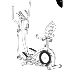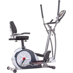
BRT3858
3-in-1 Trio Trainer
OWNER’S MANUAL
* This item is for consumer use only and it is not meant for commercial use.
OWNER’S MANUAL
* This item is for consumer use only and it is not meant for commercial use.
U.S. Patent US9474925B1
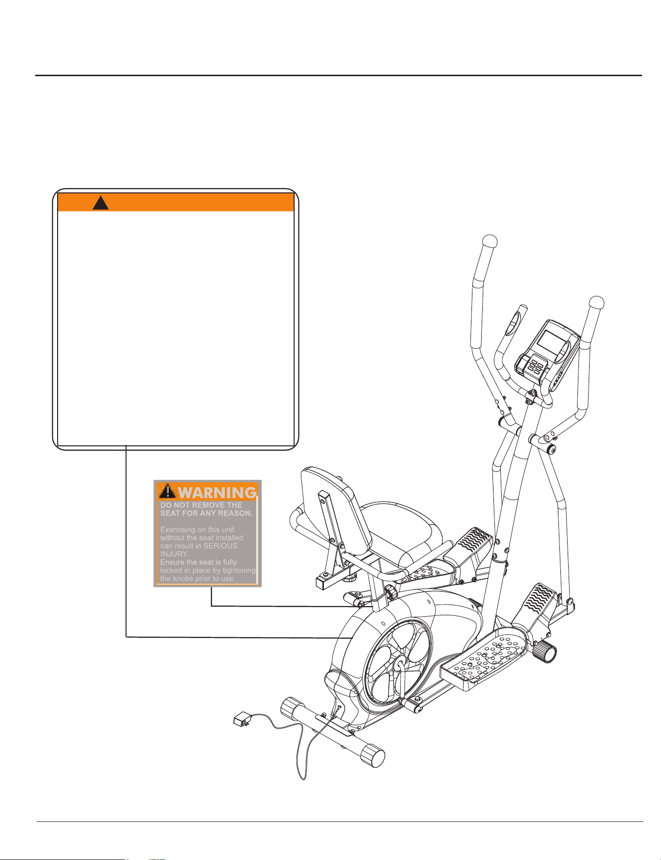
WARNING: SERIOUS INJURIES AND EVEN DEATH CAN OCCUR IF THE PROPER SAFETY PRECAUTIONS ARE NOT FOLLOWED.
The diagram below highlights and reviews many of the important Safety and Warning labels also found
on the unit. Please ensure any user of the unit familiarizes themselves with these Safety and Warning
guidelines before use.
PLEASE KEEP THESE INSTRUCTIONS FOR FUTURE USE & REFERENCE.
DO NOT DISCARD.
BRT 3858
Page 1
The use of this exercise equipment involves a RISK OF PHYSICAL
INJURY as well as property damage which can be minimized by
observing the following guidelines:
1. ALWAYS wear comfortable
clothing and shoes with good
traction.
2. ALWAYS make sure all nuts
and bolts are secured before
use. TIGHTEN PEDAL HINGE
BOLTS EVERY 30 DAYS.
3. STOP EXERCISING if you
become dizzy, nauseous, have
irregular heartbeats or breathing
difficulties. Contact your physician
immediately.
4. ALWAYS keep a large mat
under the Equipment to protect
the floor or carpet.
5. ALWAYS use your Equipment
in a warm, dry, level, well-lit, and
ventilated indoor area.
7. ALWAYS keep your
Equipment clean and free
of dust, moisture, debris
and loose objects.
8. NEVER use the Equipment
if you are injured or have
a physical condition that
impairs your balance. DO
NOT exercise under the
influence of medication or
alcohol.
9. NEVER allow small children
or pets to approach the
Equipment. It is not a toy.
10.NEVER use the Equipment
if you exceed its weight limit
of 250 lbs.
11.NEVER use the Equipment
if it does not function
properly.
6. ALWAYS keep body and
clothing free and clear of all
moving parts.
W A R N I N G !
!
General Information
Warranty
Body Flex Sports warrants your product for
a period of 1 year for the frame and 90 days
on all parts if the item is used for the intended
purpose, properly maintained and not used
commercially. Any alterations or incorrect
assembly of the product will void this warranty.
Proof of purchase must be presented for any
warranty validation (no exceptions). This
warranty applies to the original purchaser only
and is not transferable.
This warranty does not cover abuse or defects
caused during use, storage or assembly.
During the warranty period, Body Flex Sports
reserves the right to:
a). provide replacement parts to the
purchaser in an effort to repair the item.
b). repair the product returned to our
warehouse (at the purchaser’s cost).
c). replace the product if neither of the two
previously mentioned actions effect repair.
This warranty does not cover normal wear and
tear on upholstery.
Questions
If you have any questions concerning the
assembly of your item or if any parts are
missing, please DO NOT RETURN THE
ITEM TO THE STORE OR CONTACT THE
RETAILER. Our dedicated customer service
staff can help you with any questions you may
have regarding the assembly of this unit and
can also mail you replacement parts.
Customer Support
Customer Support is open 9:00 a.m. to 5:00
p.m. (Pacific Time) Monday through Friday.
Please contact us by any of the following
means.
Body Flex Sports, Inc.
21717 Ferrero Parkway, Walnut, CA 91789
Telephone: (888) 266 - 6789
Fax: (909) 598 - 6707
Email: info@bodyflexsports.com
Safety
Before you undertake any exercise program,
please be sure to consult with your doctor.
Frequent strenuous exercise should be
approved by your doctor and proper use
of your product is essential. Excessive or incorrect
training may result to health injuries. Please read
this manual carefully before commencing the
assembly of your product or starting to exercise.
• Please keep all children away from this item
when in use. Do not allow children to climb or
play on them when they are not in use.
• Supervise teenagers while they use this unit.
• For your own safety, always ensure that there
is at least 3 feet of free space in all directions
around your product while you are exercising.
• Regularly check to see that all nuts, bolts and
fittings are securely tightened. Periodically
check all moving parts for obvious signs of
wear or damage.
• Clean only with a damp cloth, do not use
solvent cleaners. If you are in any doubt, do
not use your product; contact CUSTOMER
SUPPORT.
• Before use, always ensure that your product
is positioned on a solid, flat surface. If
necessary, use a rubber mat underneath to
reduce the possibility of slipping.
•
Always wear appropriate clothing and
footwear such as training shoes when
exercising. Do not wear loose clothing that
could become caught in moving parts during
exercise.
• Do not use this unit if it is not functioning
properly or if it is not fully assembled.
• Do not use this unit for commercial purposes.
This unit is for home use only.
Storage and Use
Your product is intended for use in clean
dry conditions. You should avoid storage in
excessively cold or damp places as this may
lead to corrosion and other related problems.
Weight Limit
Your product is suitable for users weighing:
250 pounds or less.
• Before use, you must read and understand all
instructions & warnings stated in this Owner’s
Manual as well as posted on the equipment.
• It is the facility owner’s responsibility to properly
instruct users on the proper operation of the
equipment and to warn them of the potential
hazards.
• If at any time during exercise you feel faint, dizzy
or experience pain, stop and consult your
physician.
Assembling Tools
- Ruler with both metric and English measurements
- 2 x Adjustable Wrenches
- 1 x Philips (”Crosshead”) Screw Driver
•
Any adjustment devices that could interfere with
the user's movement on this unit should not be
left projecting.
Page 2
BRT 3858
Hardware List
Page 3
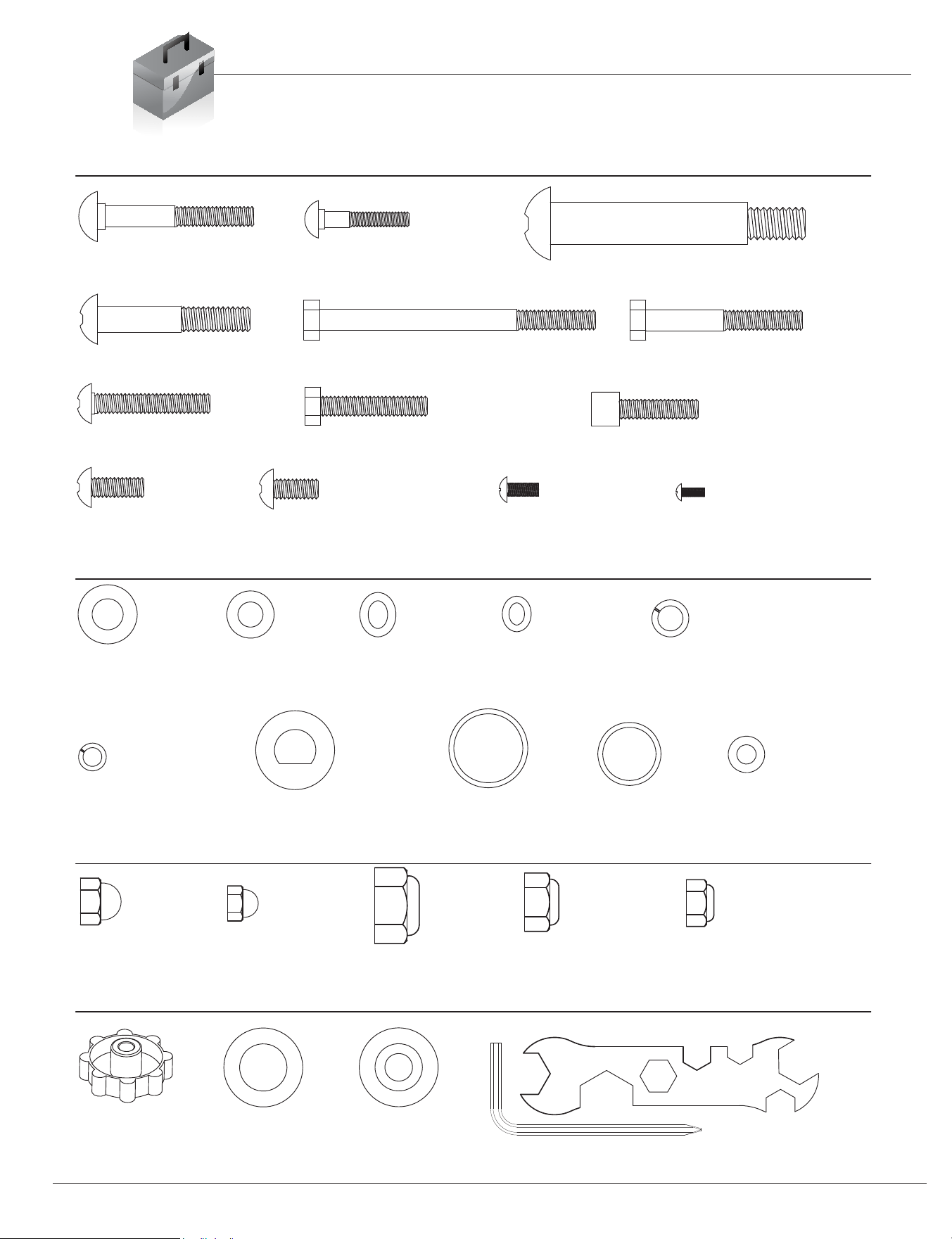
The following hardware is used to assemble your unit. Please take a moment to familiarize yourself with these items.
Please note, most of these parts are already pre-assembled on your unit. Do not be alarmed if you see parts on this
page that are not included in your hardware packet.
NUTS
WASHERS
BOLTS
#20. Carriage Bolt (M8x65 mm)
[4 Pieces]
#21. Carriage Bolt (M6x38 mm)
[4 Pieces]
#22. Bolt (1/2"x97 mm)
[2 Pieces]
#23. Bolt (M10x58 mm)
[2 Pieces]
#24.Hex Bolt (M8x105 mm)
[4 Pieces]
#25. Hex Bolt (M8x60 mm)
[2 Pieces]
#26. Bolt (M8x45 mm)
[2 Pieces]
#28. Hex Bolt (M8x40 mm)
[6 Pieces]
#29. Bolt (M8x30 mm)
[2 Pieces]
#30. Bolt (M8x20 mm)
[4 Pieces]
#31. Bolt (M8x15 mm)
[12 Pieces] Pre-assembled
[8 Pieces]
#32. Screw (M5x12 mm)
[4 Pieces]
Pre-assembled
#39. Washer (M10)
[4 Pieces]
Pre-assembled
[2 Pieces]
#40. Washer (M8)
[22 Pieces]
#41. Arc
Washer (M8)
[12 Pieces]
Pre-assembled
[8 Pieces]
#42 Arc Washer (M6)
[4 Pieces]
#43. Spring Washer (M8)
#44. Spring Washer (M6)
[4 PIeces]
#45. D Shape Washer
(19 mm)
[2 Pieces]
#34. Cap Nut (M8)
[4 Pieces]
#35. Cap Nut (M6)
[4 Pieces]
#36. Nylon N
ut (1/2")
[2 Pieces]
#37. Nylon Nut (M10)
[2 Pieces]
#50. Lock Knob (M10)
[2 Pieces]
Pre-assembled
#64. Round Cap
(38 mm
)
[2 Pieces]
Others
#80. Tool [1 Piece]
#81. Tool [2 Pieces]
#83. Screw (M4x12 mm)
[4 Pieces]
Pre-assembled
#38. Nylon Nut (M8)
[12 Pieces]
[14 Pieces]
Pre-assembled
[8 Pieces]
#46. Special Washer
(ID.19 mm)
[2 Pieces]
#47. Special Washer
(ID.16 mm)
[2 Pieces]
#82. Washer (M4)
[4 Pieces]
Pre-assembled
#63. Plastic Bushing
[2 Pieces]
BRT 3858

BRM 3670 Stride Cycle Page ?
Parts Listing
The following parts list describes all of the parts illustrated on the
exploded diagram on the following page. Please note, most of
these parts are already pre-assembled on your unit.
Page 4
Part# Description Part# Description
01 Main Frame 42 Arc Washer (M6)
02 Center Post 43 Spring Washer (M8)
03A 44 Spring Washer (M6)
04A 45 D Shape Washer (19 mm)
05 Left Coupler Bar 46 Special Washer (ID.19 mm)
06 Right Coupler Bar 47 Special Washer (ID.16 mm)
07 Seat Cushion Frame 48 Bushing
08 Backrest Cushion Frame 49 Spring Loaded Knob (M16)
09 Horizontal S
eat Cushion Bar 50 Lock Knob (M10)
10 Left Rear Handle Bar 51C
11 Right Rear Handle Bar 52A
12 Left Handle Bar 53A
13 Right Handle Bar 54A
14 Pulse Handle Bar 55A
15 Front Stabilizer 56 Left Pedal
16 Rear Stabilizer 57 Right Pedal
17 Pedal Connection Joint 58 Left Foot P
edal
18 U Bracket 59 Right Foot Pedal
19 Crank 60 Mat
20 Carriage Bolt (M8x65 mm) 61 End Cap for Fr
ont Stabilizer
21 Carriage Bolt (M6x38 mm) 62 End Cap for Rear Stabilizer
22 Bolt (1/2"x97 mm) 63 Plastic Bushing
23 Bolt (M10x58 mm) 64 Round Cap (38 mm)
24 Hex Bolt (M8x105 mm) 65 Plastic Bushing (38 mm)
25 Hex Bolt (M8x60 mm) 66 Plastic Bushing (25 mm)
26 Bolt (M8x45 mm) 67 Elliptical Sleeve
27 Hex Bolt (M8x45 mm) 68 Round End Cap (30 mm)
28 Hex Bolt (M8x40 mm) 69 Round End Cap (25 mm)
29 Bolt (M8x30 mm) 70 Round End Cap (22 mm)
30 Bolt (M8x20 mm) 71 Rectangular End Cap (25x50 mm)
31 Bolt (M8x15 mm) 72 Rectangular End Cap (25x40 mm)
32 Screw (M5x12 mm) 73 Square End Cap (38 mm)
33 Screw (M4x25 mm)
74 Foam Grip for Handle Bar
34 Cap Nut (M8) 75 Foam Grip for Rear Handle Bar
35 Cap Nut (M6) 76 Foam Grip for Pulse Handle Bar
36 Nylon Nut (1/2") 77 Monitor Base
37 Nylon Nut (M10) 78 Backrest Cushion
38 Nylon Nut (M8) 79 Seat Cushion
39 Washer (M10) 80 Tool
40 Washer (M8) 81 Tool
41 Arc Washer (M8)
BRT 3858
Left Pedal Tube
Rigth Pedal Tube
Monitor
82
83
Washer (M4)
Screw (M4x12 mm)
Hand Pulse
Main Sensor (Upper)
Main Sensor (Lower)
Adapter
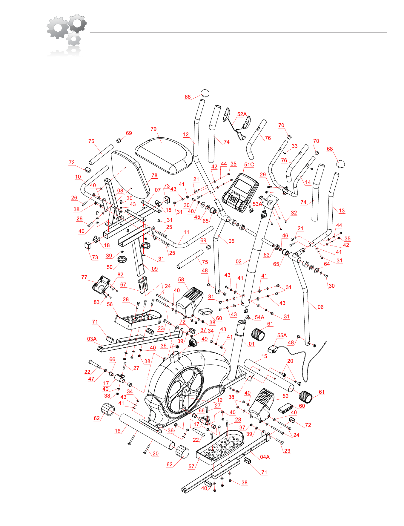
The following diagram is provided to help you familiarize yourself with the parts and
hardware that will be used during the assembly process. Please note that not all of the
parts and hardware you see here will be used while you are assembling the machine
because some of these items are already pre-installed. Please continue to the next
page to begin the assembly process and use this page only as a reference guide for
parts and hardware.
Exploded Diagram
Page 5
BRT 3858
Hardware RequiredA s s e m b l y S t e p 1
NUTS
WASHERS
BOLTS
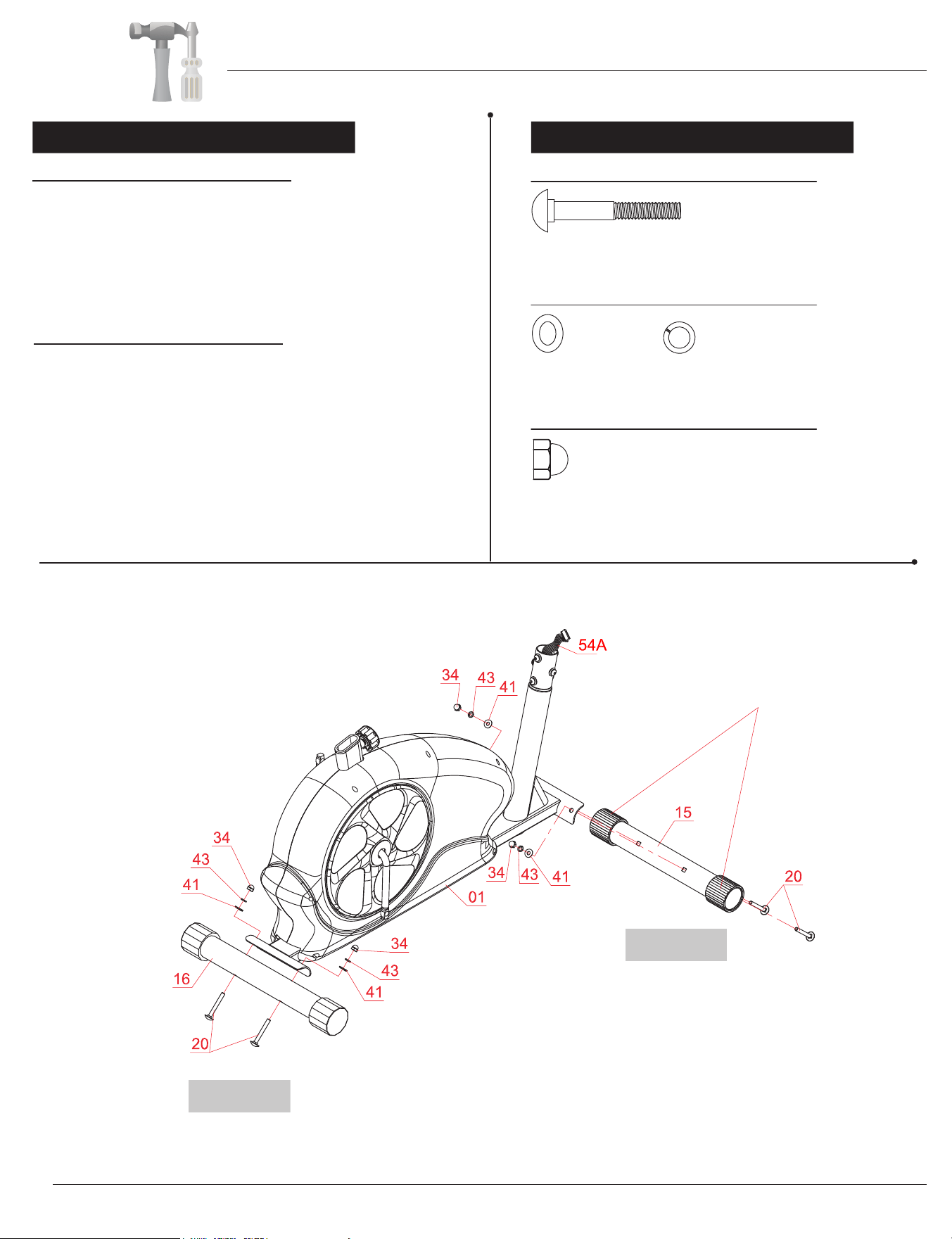
FRONT STABILIZER ASSEMBLY
Using the drawing below for reference, secure the
Front Stabilizer (#15) to the Main Frame (#01) using
REAR STABILIZER ASSEMBLY
Secure the Rear Stabilizer (#16) to the Main Frame (#01)
using two Carriage Bolts (#20) followed by two Arc
Washers (#41), two Spring Washers (#43), and two
Cap Nuts (#34).
Please Note that the Front Stabilizer (#15) has end
caps that spin for ease of relocating the unit.
#20. Carriage Bolt (M8x65 mm)
[4 Pieces]
#41. Arc Washer (M8)
[4 Pieces]
#43. Spring Washer (M8)
#34. Cap Nut (M8)
[4 Pieces]
REAR
[4 Pieces]
END CAPS THAT SPIN
two Carriage Bolts (#20) followed by two Arc
Washers (#41), two Spring Washers (#43), and two
Cap Nuts (#34).
FRONT
Assembly Instructions
Page 6
BRT 3858
(After assembly is complete,
see Page 15 for instructions on
“HOW TO MOVE/TRANSPORT THE BIKE
FOR STORAGE”)
A s s e m b l y S t e p 2 Hardware Required
WASHERS
BOLTS
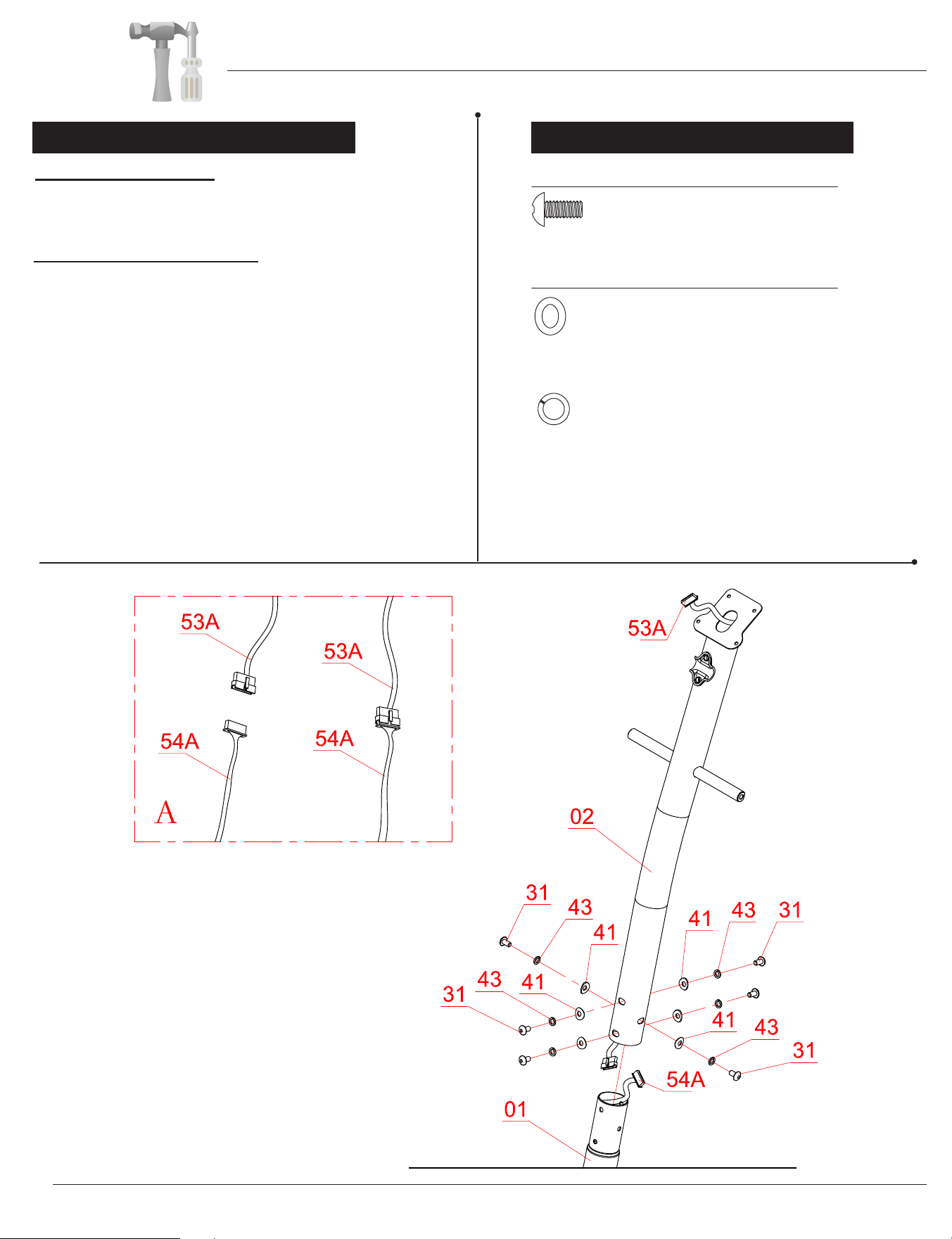
WIRE CONNECTIONS
Connect the Main Sensor Wire (Lower)(#54A) to the
Main Sensor Wire (Upper) (#53A).
CENTER POST ASSEMBLY
Remove the Bolts (#31), Spring Washers (#43),and
Arc Washers (#41) that are pre-assembled on the
Main Frame (#01) and set them aside nearby as they
will be used later in this step.
Being careful not to pinch any wires, slide the Center
Post (#02) onto the Main Frame(#01) and secure it
using the previously removed six Bolts (#31), six
Spring Washers (#43), and six Arc Washers (#41)
as shown in drawing below.
#31. Bolt (M8x15 mm)
[6 Pieces]
#41. Arc Washer (M8)
[6 Pieces]
#43. Spring Washer (M8)
[6 Pieces]
Assembly Instructions
Page 7
BRT 3858
Assembly S t e p 3
Others
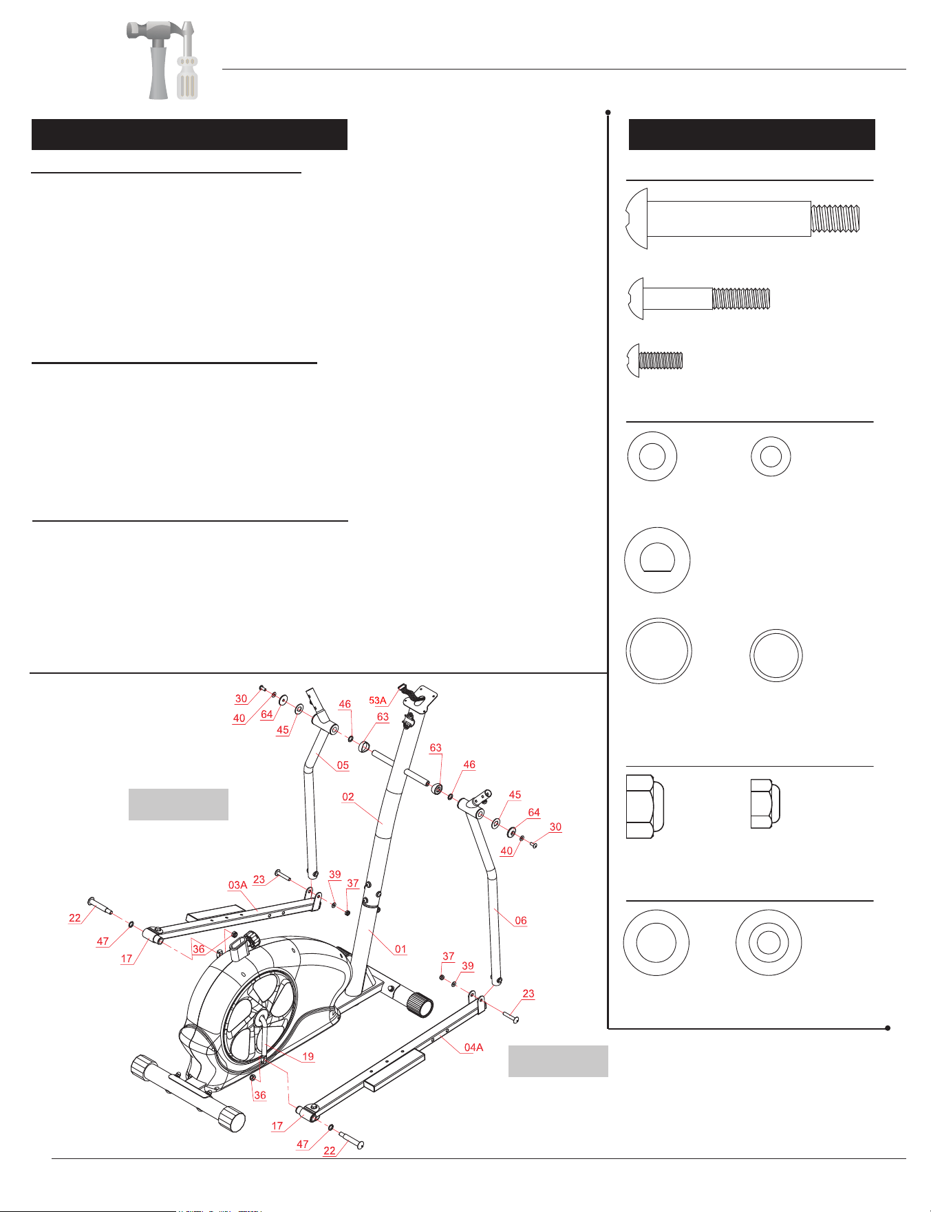
COUPLER BAR ASSEMBLY (Part I)
Referring to the diagram below, on the right side of the Center Post (#02)
–in the following order--slide on one Plastic Bushing (#63), one Special
Washer (#46) followed by the Right Coupler Bar (#06), one D Shape
Washer (#45), one Round Cap (#64), one Washer (#40), and secure
using one Bolt (#30).
On the opposite side, assemble –in the following order— slide on one Plastic
Bushing (#63), one Special Washer (#46) followed by the Left Coupler
Bar (#05), one D Shape Washer (#45), one Round Cap (#64), one
Washer (#40), and secure using one Bolt (#30).
COUPLER BAR ASSEMBLY (Part II)
Attach the Right Pedal Tube (#04A) onto the Crank (#19) as illustrated and
secure by inserting from the outer edge of the Right Pedal
Tube (#04A):
one Bolt (#22) and one Special Washer (#47). Secure from the inner side
(behind the Crank (#19)) with one Nylon Nut (#36).
Repeat this process on the other side using the
***PLEASE DO NOT tighten the hardware until PART III below has been completed.
This will allow you to align the holes for proper and smooth assembly***
Left Pedal Tube (#03A).
COUPLER BAR ASSEMBLY (Part III)
Using the drawings as reference, attach the free end of the bottom of the
Right Coupler Bar (#06) to the front of the Right Pedal Tube (#04A) by
aligning the holes. After the holes are aligned, insert one Bolt (#23)
through the Right Pedal Tube (#04A),the Right Coupler Bar (#06) and
secure using one Washer (#39) followed by one Nylon Nut (#37).
Repeat this process on the other side using Left Coupler Bar(#05) and Left
Pedal Tube (#03
tighten the hardware on both sides.
A). *** Now, you may return to PART II of this Assembly Step to
Hardware Required
NUTS
WASHERS
BOLTS
#22. Bolt (1/2"x97 mm)
[2 Pieces]
#23. Bolt (M10x58 mm)
[2 Pieces]
#30. Bolt (M8x20 mm)
[2 Pieces]
#39. Washer (M10)
[2 Pieces]
#40. Washer (M8)
[2 Pieces]
#45. D Shape Washer
(19 mm) [2 Pieces]
#36. Nylon Nut (1/2")
[2 Pieces]
#37. Nylon Nut (M10)
[2 Pieces]
#64. Round Cap
(38 mm)
[2 Pieces]
#46. Special Washer
(ID.19 mm)
[2 Pieces]
#47. Special Washer
(ID.16 mm)
[2 Pieces]
#63. Plastic Bushing
[2 Pieces]
Page 8
BRT 3858
LEFT
RIGHT
Assembly Instructions
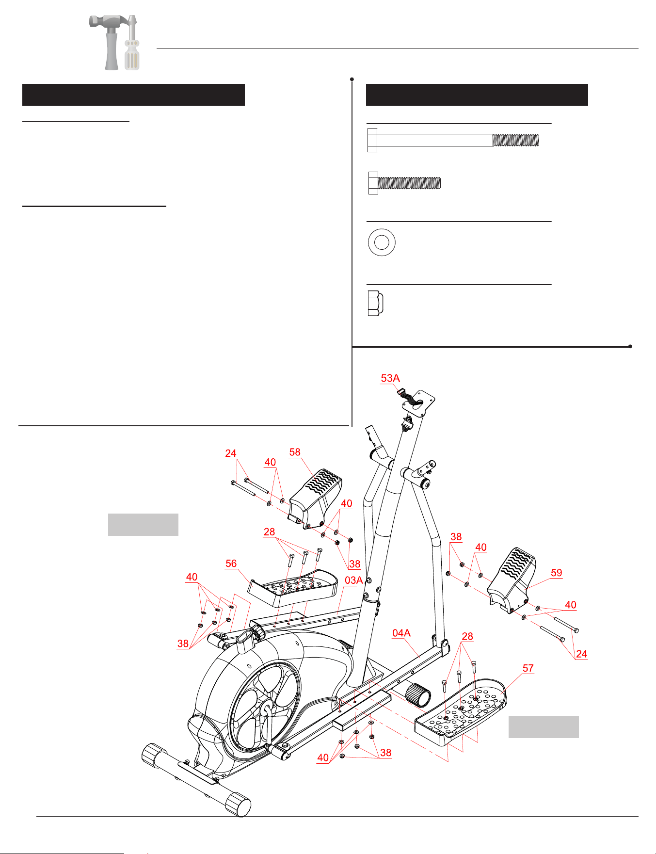
NUTS
WASHERS
BOLTS
#40. Washer (M8) [14 Pieces]
#38. Nylon Nut (M8) [10 Pieces]
PEDAL ASSEMBLY
Attach the Left/Right Pedals (#56/#57) onto the
Left/Right Pedal Tubes (#03A/#04A) as shown in the
drawing below using a total of three Hex Bolts (#28),
secured by three Washers (#40), and three Nylon Nuts (#38)..
FOOT PEDAL ASSEMBLY
On the left side, attach the Left Foot Pedal (#58) to
the front of Left Pedal Tube (#03A) using two Hex
Bolts (#24) through two Washers (#40) and secure
with two Washers (#40) and two Nylon Nuts (#38).
Repeat this process on the other side.
Hardware Required
#24.Hex Bolt (M8x105 mm)
[4 Pieces]
#28. Hex Bolt (M8x40 mm)
[6 Pieces]
Note:
Care should be used when mounting or dismounting
the equipment. Before mounting or dismounting,
move the pedal on the mounting or dismounting
side to it lowest position and bring the machine to
a complete stop.
This unit is not equipped with a free-wheel. Pedal
speed should be reduced in a controlled manner.
A s s e m b l y S t e p 4
Assembly Instructions
Page 9
BRT 3858
LEFT
RIGHT
A s s e m b l y S t e p 5 Hardware Required
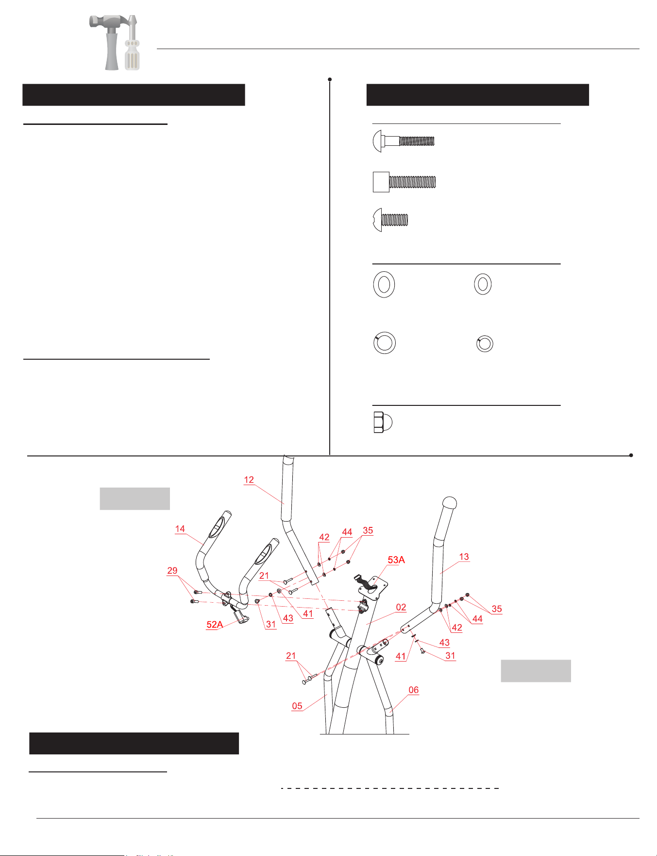
HANDLE BAR ASSEMBLY
Please remove the two Bolts (#31), two Spring
Washers (#43), two Arc Washers (#41) pre-assembled
on Left Coupler Bar (#05) and Right Coupler Bar (#06).
Set them aside nearby for now.
On the left side, insert Left Handle Bar (#12) into the
opening at the tip of Left Coupler Bar (#05). Align the
holes of the Left Handle Bar (#12) and Left Coupler
Bar (#05) and secure from the side using one Bolt (#31)
,
one Spring Washer (#43) and one Arc Washer (#41).
Then, continue from rear/front with with two Carriage
Bolts (#21), two Arc Washers (#42), two Spring
Washers (#44) and two Cap Nuts (#35) .
Repeat this process on the other side using Right
Handle Bar (#13) and Right Coupler Bar (#06).
PULSE HANDLE BAR ASSEMBLY
Install the Pulse Handle Bar (#14) onto the bracket
of the Center Post (#02) as shown in the illustration
below using two Bolts (#29). Please ensure the wire of
the Handle Pulse (#52A) is free and clear, avoiding
pinching it during this assembly step.You will need to
connect this wire to the Monitor (#51&) later.
NUTS
WASHERS
BOLTS
#21. Carriage Bolt (M6x38 mm)
[4 Pieces]
#29. Bolt (M8x30 mm)
[2 Pieces]
#31. Bolt (M8x15 mm)
[2 Pieces]
#41. Arc Washer (M8)
[2 Pieces]
#42 Arc Washer (M6)
[4 Pieces]
#43. Spring Washer (M8)
#44. Spring Washer (M6)
[4 PIeces]
#35. Cap Nut (M6)
[4 Pieces]
[2 Pieces]
LEFT
RIGHT
After complete assembly: If the computer
is not picking up your hand pulse signal
(or you are getting
inaccurate readings), Please refer to our “Troubleshooting”
section on Page 21 for other troubleshoot
issues.
HAND PULSE SIGNAL
Troubleshooting
Assembly Instructions
Page 10
BRT 3858
Hardware Required
BOLTS
#32. Screw (M5x12 mm)
[4 Pieces]
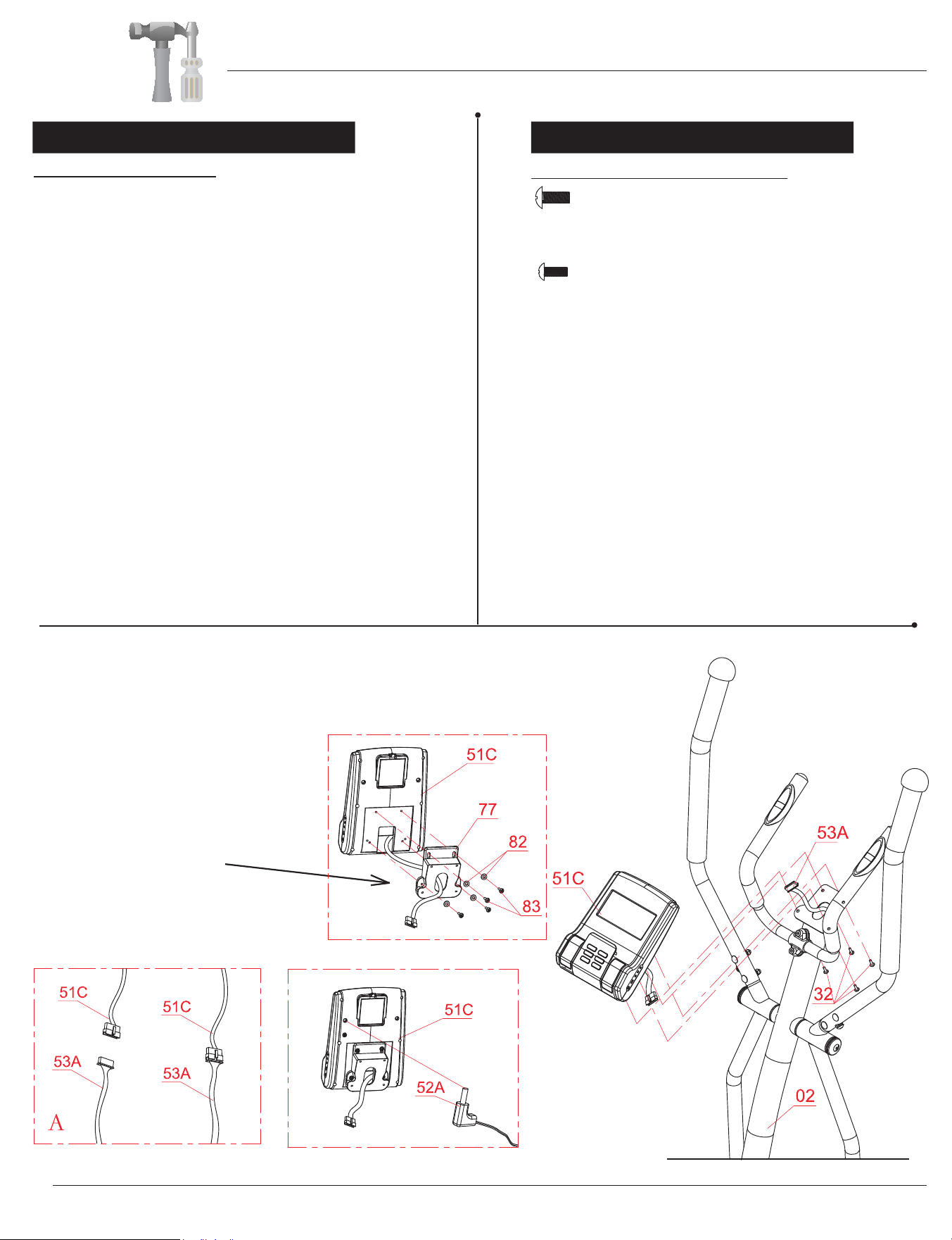
A s s e m b l y S t e p 6
Remove the four Screws (#83) and four Washers (#82)
that are pre-assembled on the Monitor (#51C) . Set
them aside nearby as they will be used later in this process.
Attach the Monitor Base (#77) to the back of the
Monitor (#51C), secure by using four Screw (#83) and
four Washers (#82) that were previously removed.
With the help of an assistant, connect the Main Sensor
Wire (Upper) (#53A) to the corresponding wire on the
Monitor (#51C)(diagram A) . Connect the end of wire
of Handle Pulse (#52A) to the Monitor (#51C) by
Attach the Monitor (#51C) to the bracket on the Center
Post (#02) by using the four Screws (#32) that were
previously removed.
MONITOR ASSEMBLY
Remove the four Screws (#32) that are pre-assembled
on the back of the 0RQLWRU%DVH . Set them aside
nearby as they will be used later in this process.
B
Make sure the wire is accessible and
exposed (as shown) before attaching
Monitor Base (#77) to the Monitor
(#51C).
#83. Screw (M4x12 mm)
[4 Pieces]
inserting it into the back hole as illustrated below
(diagram B). Being careful not to pinch/damage any of
the wires.
Assembly Instructions
Page 11
BRT 3858
Hardware RequiredA s s e m b l y S t e p 7
NUTS
WASHERS
BOLTS
#25. Hex Bolt (M8x60 mm)
[2 Pieces]
#30. Bolt (M8x20 mm)
[2 Pieces]
#39. Washer (M10)
[2 Pieces]
#40. Washer (M8)
[4 Pieces]
#43. Spring Washer (M8)
#50. Lock Knob (M10)
[2 Pieces]
Others
#38. Nylon Nut (M8)
[2 Pieces]
[2 Pieces]
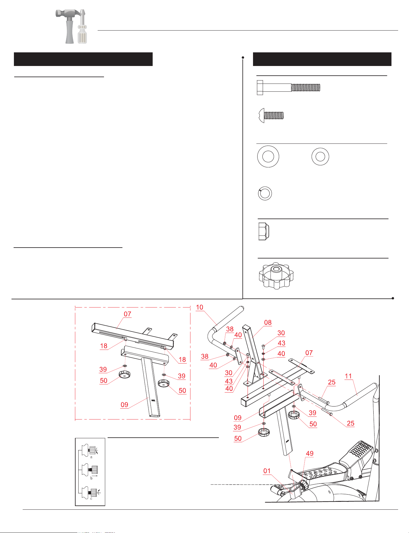
SEAT FRAME ASSEMBLY
With the help of an assistant, loosen the pre-assembled Spring
Loaded Knob (#49) and pull back slightly on it so that you
may
proceed to insert the Seat Post (#09) into the mouth of the post that
is protruding from the Main Frame (#01) down a minimum of four
inches so that the corresponding holes can engage. Screw in the
Spring Loaded Knob (#49) through the Main Frame (#01) and then
through any one of the holes located on the Seat Post (#09).
Note: The Spring Loaded Knob (#49) has a safety feature that
allows you to loosen it by turning it counter-clockwise three times as
you pull it outward. This knob can be loosened to adjust the seat
height. Adjust the seat height and then release the knob back in. Tighten
the knob by turning clockwise. See the more detailed explanation
and illustrations below.
REAR HANDLEBA
R ASSEMBLY
Next, with the help of an assistant, align the four of the Left Rear
Handle Bar (#10)
and
Right Rear Handle Bar (#11)
to the holes on the Backrest Cushion Frame (#08) and secure all
using the two Hex Bolts (#25), followed by two Washers (#40), and
two Nylon Nuts (#38).
Next, slide the Seat Cushion Frame (#07) onto the trough of the
Seat Post (#09) as shown below. Secure using two Knobs (#50)
through two Washers (#39).
Attach the Backrest Cushion Frame (#08) to the Seat Cushion
Frame (#07), secure by using two Bolts (#30), two Spring Washers
(#43) and two Washers (#40).
Assembly Instructions
Page 12
BRT 3858
Spring Loaded Knob Operation
Turn knob counter-clockwise three times.
Pull knob outward and adjust bottom frame
simultaneously.
Push knob back inward until it clicks and then
tighten it by turning clockwise.
Hardware Required
WASHERS
BOLTS
#26. Bolt (M8x45 mm)
[2 Pieces]
#31. Bolt (M8x15 mm)
[4 Pieces]
#40. Washer (M8)
[2 Pieces]
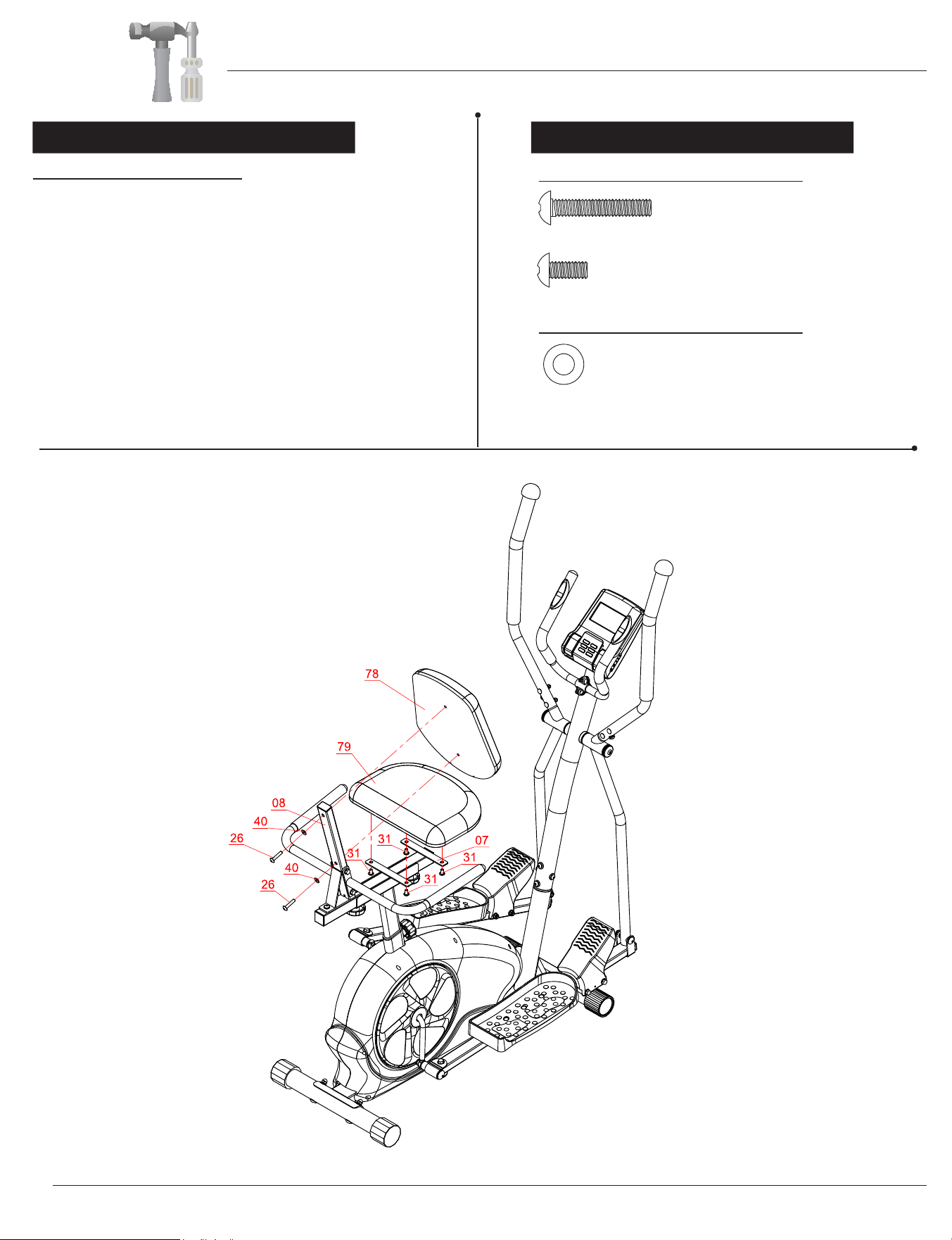
A s s e m b l y S t e p 8
CUSHION ASSEMBLY
First, attach the Seat Cushion (#79) to the horizontal
bar of the Seat Cushion Frame (#07) and secure from
the bottom using four Bolts (#31).
Then, attach the Backrest Cushion (#78) to the
Backrest Cushion Frame (#08) and secure using two
Bolts (#26) through two Washers (#40).
Assembly Instructions
Page 13
BRT 3858
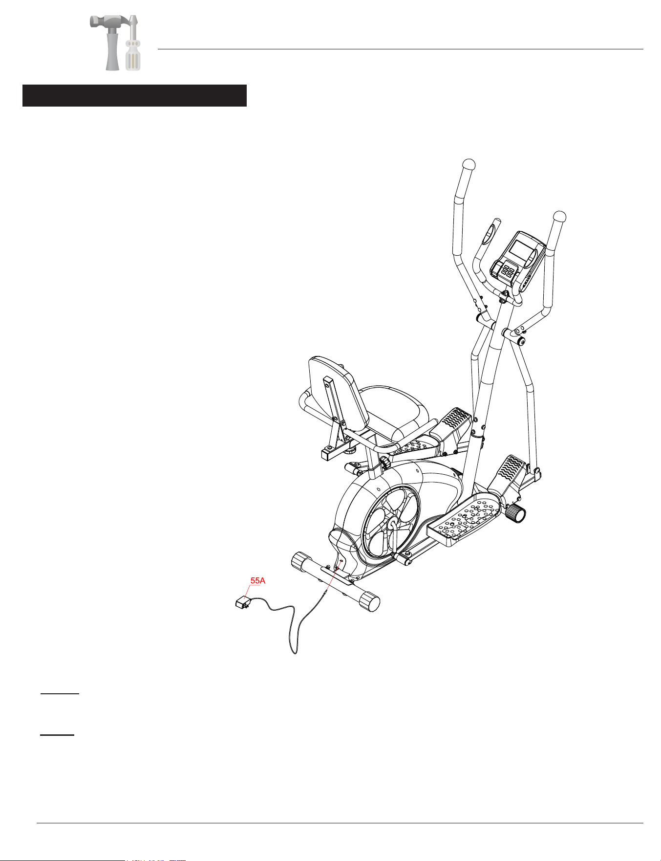
A s s e m b l y S t e p 9
Plug in the Adapter (#55A) male plug into the female socket located at the rear end of the unit.
The assembly process is now complete. However, for your own safety,
please make sure to read this entire Owner’s Manual which includes
safety instructions and warnings, as well as any safety/warning labels
affixed to the product before use.
For your safety, please visually and functionally inspect and test the unit
after assembly is complete.
Note:
This Magnetic Trio-Trainer Bike is intended
to be correctly orientated in a vertical or floor
mount position.
Page 14
Assembly Instructions
BRT 3858
NOTES (Regarding the Computer Monitor):
Warning: This device complies with Part 15 of the FCC Rules. Operation is subject to the following two conditions:
(1) This device may not cause harmful interference.
(2) This device must accept any interference received, including interference that may cause undesired operation.
Caution:
This equipment has been tested and found to comply with the limits for a Class B digital device, pursuant to part 15 of the FCC Rules.
These limits are designed to provide reasonable protection against harmful interference in a residential installation. This equipment generates,
uses and can radiate radio frequency energy and, if not installed and used in accordance with the instructions, may cause harmful interference
to radio communications. However, there is no guarantee that interference will not occur in a particular installation. If this equipment does
cause harmful interference to radio or television reception, which can be determined by turning the equipment off and on, the user
is encouraged to try to correct the interference by one or more of the following measures:- Reorient or relocate the receiving antenna.
- Increase the separation between the equipment and receiver.- Connect the equipment into an outlet on a circuit different from that to which
the receiver is connected.- Consult the dealer or an experienced radio/TV technician for help.

Safety & Maintenance
Page 15
• Make sure all nuts, bolts, and screws are tightened prior to use.
• Be sure that all adjustment locking devices and safety devices are properly engaged prior to use!
• Never over-tighten the above-mentioned devices and parts to avoid damage to the unit.
• Check for loose parts and components and make proper adjustments prior to use.
• Check to see if there are any tears or bends in the welding or metal prior to use. If tears or bends
are found, do NOT use the unit and contact our CUSTOMER SUPPORT.
• Extreme care must be taken to not allow your feet, fingers, hair, clothing, and/or any loose items to be
snagged into any portion of the bike when the unit is in motion. Failure to follow these instructions
could result in serious injury, including the loss of fingers.
• Always wait for the pedals and other moving parts (which can gain great momentum during riding) to
come to a complete stop before dismounting the unit to avoid serious injury.
• Do not use solvent cleaners. If you are in any doubt, do not use your cleansing product;
contact CUSTOMER SUPPORT.
• For any replacement warning labels, please contact our CUSTOMER SUPPORT at (888) 266-6789
or (909) 598-9876, or mail in a written request to: Body Flex Sports, Inc. 21717 Ferrero Parkway,
Walnut, CA 91789. More detailed information about how to reach our CUSTOMER SUPPORT may
be found on Page 1 of the Owner’s Manual under the “CUSTOMER SUPPORT” section.
• The specific Parts on your unit which may see possible signs of wear after prolonged use are listed as
follows (please check these parts before each use):
Left/Right Pedals (#56/57); Left/Right Handlebars (#10/11)
• Please review all safety instructions and warnings in this entire Owner’s Manual, as well as any
safety/warning labels affixed to the product before use.
MAINTENANCE & CARE
SAFETY & WARNINGS
BRT 3858
HOW TO (EMERGENCY) STOP
NOTE: Always wait for the pedals, handlebars, and/or any other moving parts (which can gain great momentum
during riding) to come to a complete stop before dismounting the unit to avoid serious injury.
1. To reduce speed on the bike, you may use the combinations of your feet on the Left/Right Pedals (#56/57)
and your hands on any set of the handlebars (Left/Right Rear Handle Bars (#10/11) or Left/Right Handle
Bars (#12/13) or Pulse Handle Bar (#14)) to gently and safely apply counter-momentum.
2. Wait for the pedals and handlebars to come to a complete stop.
3. Now you may safely dismount the unit.
NOTE: To safely move, transport, and/or store the unit, please seek the help of capable assistants (minimum 2
HOW TO MOVE/TRANSPORT THE BIKE FOR STORAGE
people total).The unit has integrated End Cap for Front Stabilizers (#61) purposely intended to ease this process.
1. Position one person on each side at the rear of the bike toward the Seat (one person on the left, and one
on the right).
2. Have each person use the hand closest to grip the respective Left/Right Rear Handle Bar (#10/11). Then,
use the other hand to grip the respective Left/Right Handle Bar (#12/13). (These are the safest areas to avoid
injury during this process.)
3. Have both people simultaneously lift the unit to move/transport the unit to the desired area.
Page 16
BRT 3858
Computer Operation
The monitor is designed for programmable magnetic bikes and introduced with the following categories:
- Key Functions
- About Display
- Operating Ranges
- Things You Should Know Before Exercising
- Operation Instructions
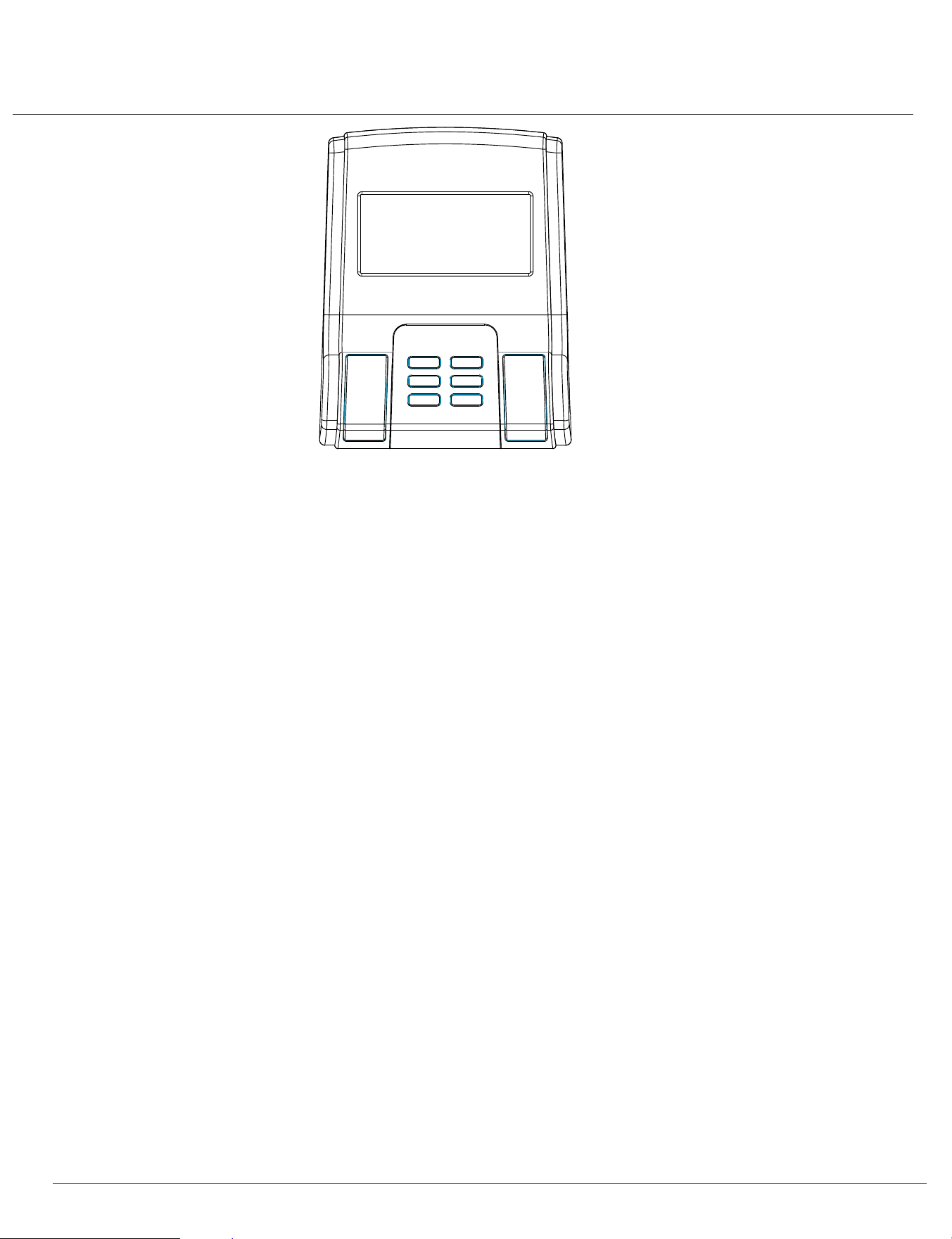
FUNCTION KEYS (on the surface of the fitness monitor)
There are total 6 keys including START/STOP, ENTER, MODE, UP, DOWN, and TEST ( RECOVERY).
START/STOP: Start or stop the program chosen. And, reset the monitor by pressing and holding for 2 seconds.
ENTER: Choose the functions from PROGRAMS, GENDER, TIME, HEIGHT, WEIGHT, DISTANCE, CAL, WATT, TARGET HEART
RATE, AGE, and 10 columns. The chosen function will flash. Please note that not all the functions can be selected in every program
according to the types of each program.
MODE: Change the displays of the values between RPM or SPEED, DISTorODOand CAL or WATT.
UP(▲)
: Select or increase the values of PROGRAMS, GENDER, TIME, HEIGHT, WEIGHT, DISTANCE, CAL, WATT, TARGET HEART
RATE, AGE, and 10 columns.
DOWN (▼): Select or decrease the values of PROGRAMS, GENDER, TIME, HEIGHT, WEIGHT, DISTANCE, CAL, WATT, TARGET
HEART RATE, AGE, and 10 columns.
TEST(RECOVERY): Start the function of PULSE RECOVERY.
Computer Operation
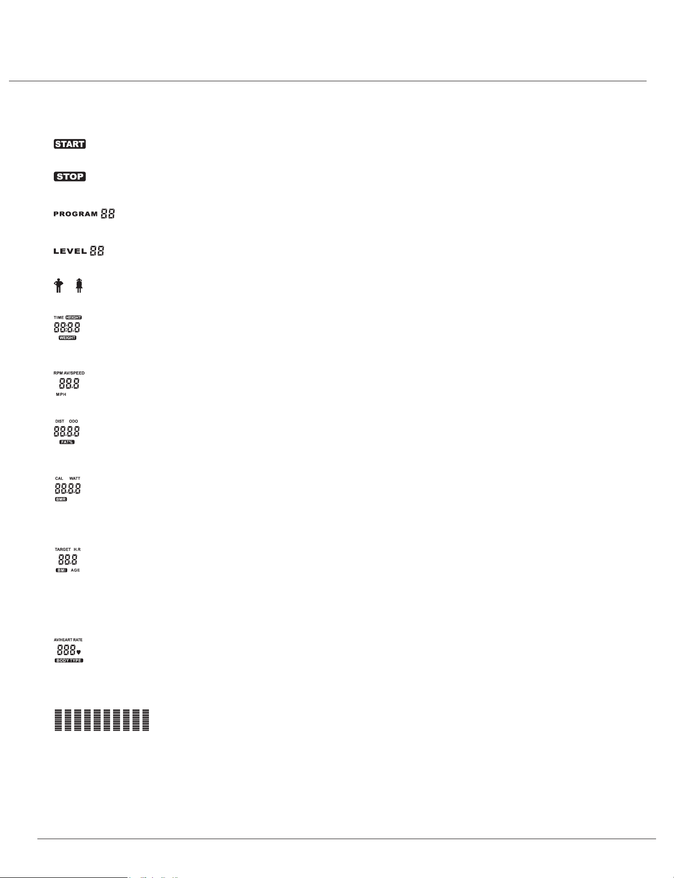
ABOUT DISPLAY
A. START: Indicate the selected program has started.
B. STOP: Indicate the selected program has stopped. And, users are free to change the programs and the value of functions applied.
C. PROGRAMI nnd: icate the selected programs from PROGRAM 1 to PROGRAM 17.
D. LEVEL n: Indicate the selected level of loading from LEVEL 1 to LEVEL 24.
E. GENDEIRnd: icate the selected gender (Male or Female).
F. TIME/HEIGHT/WEIGHT DisplaInyd: icate only one value of TIME, HEIGHT, or WEIGHT displayed depending on the programs.
G. RPM/SPEED/ Displa y :I ndicate only one value of RPM, SPEED, or MPH displayed depending on the programs.MPH
H. DISTANCE/FAT% Display: Indicate only one value of DISTANCE or FAT% displayed depending on the programs.
I. CAL/WATT/BMR Display: Indicate only one value of CAL, WATT, or BMR displayed depending on the programs.
J. TARGET H.R./BMI/AGE Display : Indicate only one value of TARGET HEART RATE. BMI or AGE displayed depending on the
programs.
K. HEART RATE/BODY TYPE Display: Indicate only one value of HEART RATE or BODY TYPE displayed depending
on the programs.
L. LOADING Profiles : There are 10 columns of loading bars and 12 bars in each column. Each column represents 3 minutes work
out (without the change of TIME value), and each bar represents 2 levels of loading.
Page 17
BRT 3858
Computer Operation
OPERATING RANGES
THINGS YOU SHOULD KNOW BEFORE EXERCISING
1. The values calculated or measured by the computer are for exercise purpose only, not for medical purpose.
2. The variables may be changed in different programs:
3. Programs Selection:
There are programs with 1 Recovery including 1 Manual Program, ,1 Body Fat Program, Heart Rate Control 17 46 Preset Programs
Program , 1 Speeds 4 User Setting Programs,
Independent Program, and 1 Pulse Recovery Measuring.
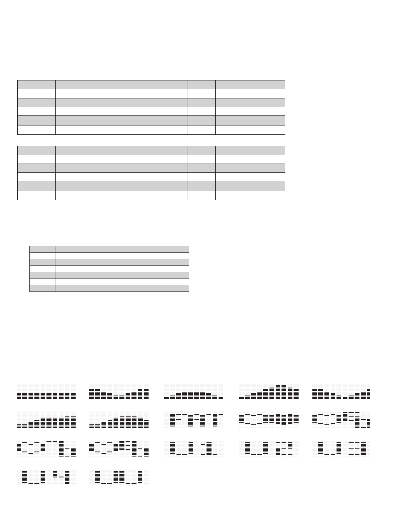
4. Program Graph:
Each graph shown is the profile of the loading in each interval (column). With the value of TIME counting up, each interval is 3
minutes that all the columns make up 30 minutes. With the value of TIME counting down, each interval is the value of setup TIME
divided by 10. For example, if the time value is set up to 40 minutes, each interval will be 40 minutes divided by 10
intervals(40/10=4). Then, each interval will be 4 minutes. The following graphs are all the profiles in the monitor.
Value Range (Count Up) Count Down Preset Increment (Decrement)
PROGRAM
1~17 17~1 1 1
LEVEL 1~24 24~1 N/A 1
GENDER Male/Female N/A Male N/A
TIME 0:00~99:59
Manual PRO 99:00~1:00
Other PRO 99:00~5:00
0:00 1:00
HEIGHT 40~100 100~40 70 1
Value Range (Count Up) Count Down Preset Increment (Decrement)
WEIGHT (lbs)
44~330 330~44 150 1
DISTANCE ( ) mile 0.00~99.99 99.90~0.00 0.00 0.1
WATT 20~400 400~20 100 5
TARGET H.R. 60~220 220~60 120 1
AGE 10~99 99~10 35 1
Program 5Program 1 Program 2 Program 3 Program 4
Program 7 Program 8(Body Fat)
Prog
ram 6 Program 9(Ta rget H.R.C.) Program 10(60%H.R.C.)
Program 13(User Setting) Program 14(User Setting)
Program 11(70%H.R.C.) Program 12(80%H.R.C.) Program 15(User Setting)
Program 17(Watt Control)
Program 16(User Setting)
(in)
Programs Variables
P1~P
7 TIME, DISTANCE, CAL, AGE
P8 GANDER, HEIGHT, WEIGHT, AGE
P9 TIME, DISTANCE, CAL, TARGET H.R.
P10~P12 TIME, DISTANCE, CAL, AGE
P13~P16 TIME, DISTANCE, CAL, AGE, 10 intervals
P17 TIME,DISTANCE, WATT, AGE
Page 18
BRT 3858

Computer Operation
OPERATION INSTRUCTIONS
Exercising with specific goal:
• TIME Control: Set up a period of time to exercise.(Except in Program 2)
• DISTANCE Control: Set up a certain distance to exercise. (Except in Program 2)
• BODY FAT Control: Computer designs various programs for different people with different body fat rate.
• WATT Control: Keep different bodies burning in desirous WATT condition
Pulse Rate:
The whole set of heart rate detector includes 2 sensors each side. Each sensor has 2 pieces of metal parts. The correct way to get
detected is to gently hold both metal parts each hand. With the good signals picked up by the computer, the heart mark in the HEART
RATE/ BODY TYPE Display will flash.
(Options: Chest Belt for wireless pulse system is optional. If wireless pulse system is adapted, please refer to the leaflet of wireless
pulse system. It may not apply to all the models, only if the option is along with the computer.)
Manual Program:
Program 1 is a manual program. Press “ENTER” key to select TIME, DISTANCE, CAL, and AGE. Then, press ▲ or ▼ key to adjust the
values. The default level of loading is 6. After pressing “START/STOP” key to exercise, please also apply the heart rate detector
appropriately. Users may exercise at any desired level (by pressing ▲ or ▼ during the workout) with a period of time or a certain dis -
tance. With the input of age, the computer may suggest a target heart rate to exercise. The suggested heart rate is 80% (220-age). So,
if the heart rate detected equals to or greater than the TARGET H.R., the value of HEART RATE will keep flashing.
Please note that it is a warning for users to slow down or to lower the level of loading.
Preset Programs:
Program2 to Program7 is the preset programs. Press “ENTER” key to select TIME, DIST
ANCE, CAL, and AGE. Then, press ▲ or ▼
key to adjust the values. Users may exercise with different level of loading in different intervals as the profiles show.
After pressing
“START/STOP” key to exercise, please also apply the heart detector appropriately. Users may also exercise at any desired level
(by pressing ▲ or ▼ during the workout) with a period of a certain distance. With the input of age, the computer may suggest a target
heart rate to exercise. The suggested heart rate is 80% (220-age).
So, if the heart rate detected equals to or greater than the TARGET H.R., the value of HEART RATE will keep flashing. Please note that
it is a warning for users to slow down or to lower the level of loading.
5. Body Types:
There are 4 body types divided according to the FAT% calculated.
6. BMR: Basal Metabolic Rate
7. BMI: Body Mass Index
Type Man Woman
Type 1
(FAT=0.0%~13.0%) (FAT=0.0%~23.0%)
Type 2 (FAT=13.1%~25.8%) (FAT=23.1%~35.8%)
Type 3 (FAT=25.9%~30.0%) (FAT=35.9%~40.0%)
Type 4 (FAT=30.1%~50.0%) (FAT=40.1%~50.0%)
Page 19
BRT 3858

Computer Operation
Body Fat Program:
Program is a special program designed to calculate users' body fat ratio and to design a specific loading profile for users. With 4 8
different body types, the computer can generate 4 different profiles for each. Press “ENTER” key to select GENDER, HEIGHT WEIGHT
,
and
AGE. Then, press ▲ or ▼ key to adjust the values. After pressing “START/STOP” key to calculate body fat, please also apply the
heart rate detector appropriately. If the detector cannot pick up any signals, an error message "Err" will show up in the profile display. If
it happens, press “START/STOP” key to calculate again. Then, the calculation values of FAT%, BMR, BMI, BODY TYPE, and
a designed profile will show up shortly. Press “START/STOP” key to exercise. The profile shown in the display is specially designed for
your body type.
Heart Rate Control Program:
User Setting Programs:
Program 13 to Program 16 are the user setting programs. Users are free to edit the values in the order of TIME, DIST
ANCE, CAL,
AGE,
and the level of loading in 10 intervals. The values and profiles will be stored in the memory after setup. After pressing “START/STOP”
key to exercise, please also apply the heart rate detector appropriately. Users may also change the ongoing loading in each interval
by pressing ▲ or ▼ key, and they will not change the level of loading stored in the memory. With the input of age, the computer may
suggest a target heart rate to exercise.
The suggested heart rate is 80% (220-age). So, if the heart rate detected equals to or greater than the TARGET H.R., the value of
HEART RATE will keep flashing. Please note that it is a warning for users to speed down or to lower the level of loading.
Speed Independent Program:
Program independent program. Press “ENTER” key to select the values of TIME DIST17 is a speed
ANCE, W
ATT, and AGE. Then, press
▲ or ▼key to adjust the values. After pressing “START/STOP” key to exercise, please also apply the heart rate detector appropriately.
During the exercise, the level of loading is not adjustable. In this program, the computer will adjust the level of loading according to
the value of WATT setup. For example, the level of loading may increase while the speed is too slow. Also, the level of loading may
decrease while the speed is too last. As a result, the calculated value of WATT will close to the value of WATT setup by users. With the
input of age, the computer may suggest a target heart rate to exercise. The suggested heart rate is 80%(220-age). So, if the heart rate
detected equals to or greater than the TARGET H.R., the value of HEART RATE will keep flashing.
Please note that it is a warning for users to sleep down or to lower the level of loading.
Pulse Recovery:
It is a function to check the condition of pulse recovery that is scaled from 1.0 to 6.0 while 1.0 means the best and 6.0 means the worst
and the increment is 0.1. In order to get rated correctly, users must test it right after the workout finished by pressing
“TEST(RECOVERY)” key and then stop exercising. After the key is pressed, please also apply the heart rate detector appropriately,
the test will last for 1 minute and the result will show in the display. If the computer does not detect your current heart rate, pressing
“TEST(RECOVERY)” will not enter into the pulse recovery test. During the pulse recovery test, press “TEST(RECOVERY)” to exit the
test and return to the stop status.
Program 9 to Program12 are the heart rate control programs(H.R.C.).
In Program9, press “ENTER” key to select TIME DISTANCE,
CAL, and TARGET H.R. Users may setup a target heart rate to exercise in a period of time or a certain distance. In program 10 to
program 12, press “ENTER” key to select TIME, DISTANCE, CAL, and AGE. Then, press ▲ or ▼key to adjust the values. Users may
exercise in a period of time or a certain distance with 60% max heart rate in program 10, and 70% max heart rate in program 11, and
80% max heart rate in Program 12, After pressing “START/STOP” key to exercise, please also apply the heart rate detector
appropriately. In these programs, the computer will adjust the level of loading according to the heart rate detected. For example, the
level of loading may increase while the heart rate detected is lower than TARGET H.R. Also, the level of loading may decrease while
the heart rate detected is higher than TARGET H.R. As a result, the user's heart rate will be adjusted to close to the TARGET H.R. in
the range of TARGET H.R.-5 and TARGET H.R.+5.
Page 20
BRT 3858

Troubleshooting
If the computer is not picking up your hand pulse signal (or you are getting
inaccurate readings), please adjust the following:
1. Slightly moisten/dampen the palms with water so the sensors can detect a
pulse signal.
2. Do not grip the sensors too tightly. Only moderate pressure need be applied.
Gripping the sensors too tightly restricts and seizes detection of your pulse.
3. Remove any rings or jewelry to prevent interference.
4. Check to ensure all pulse sensor wires are properly connected and are
not damaged.
You may need to refer to installation/assembly directions for the pulse sensor
wires in this manual.
If the computer is not displaying the CALORIES/DISTANCE/TIME/(ETC.) functions
(or you are getting inaccurate readings), please adjust the following:
1. Check to ensure all computer sensor wires are properly connected and are
not damaged.
You may need to refer to installation/assembly directions for the sensor wires
in this manual.
If the computer display is blank & not displaying any data (or does not appear to
power on), please adjust the following:
1. Check to ensure all sensor wires are all properly connected and are
not damaged.
2. Check to ensure the AC Adapter* or Batteries* are properly plugged in or
fully charged.
Troubleshoot Area
HAND PULSE SIGNAL
CALORIES/DISTANCE/
TIME/(ETC.)
COMPUTER Display
(AFTER COMPLETE ASSEMBLY)
Solution
*Please check your product manual to determine if your model uses either
1. an AC Adapter, or 2. Batteries to power your unit.
For your safety, please do not discard this Troubleshooting sheet or the Owner’s Manual, and keep them in a place where you can easily
access/refer to them at any time. If you are still having any troubleshooting issues, please contact our Customer Support for further assistance.
Page 21
BRT 3858
Before use, you must read and understand all instructions & warning stated in this Owner's Manual as well as
posted on the equipment.
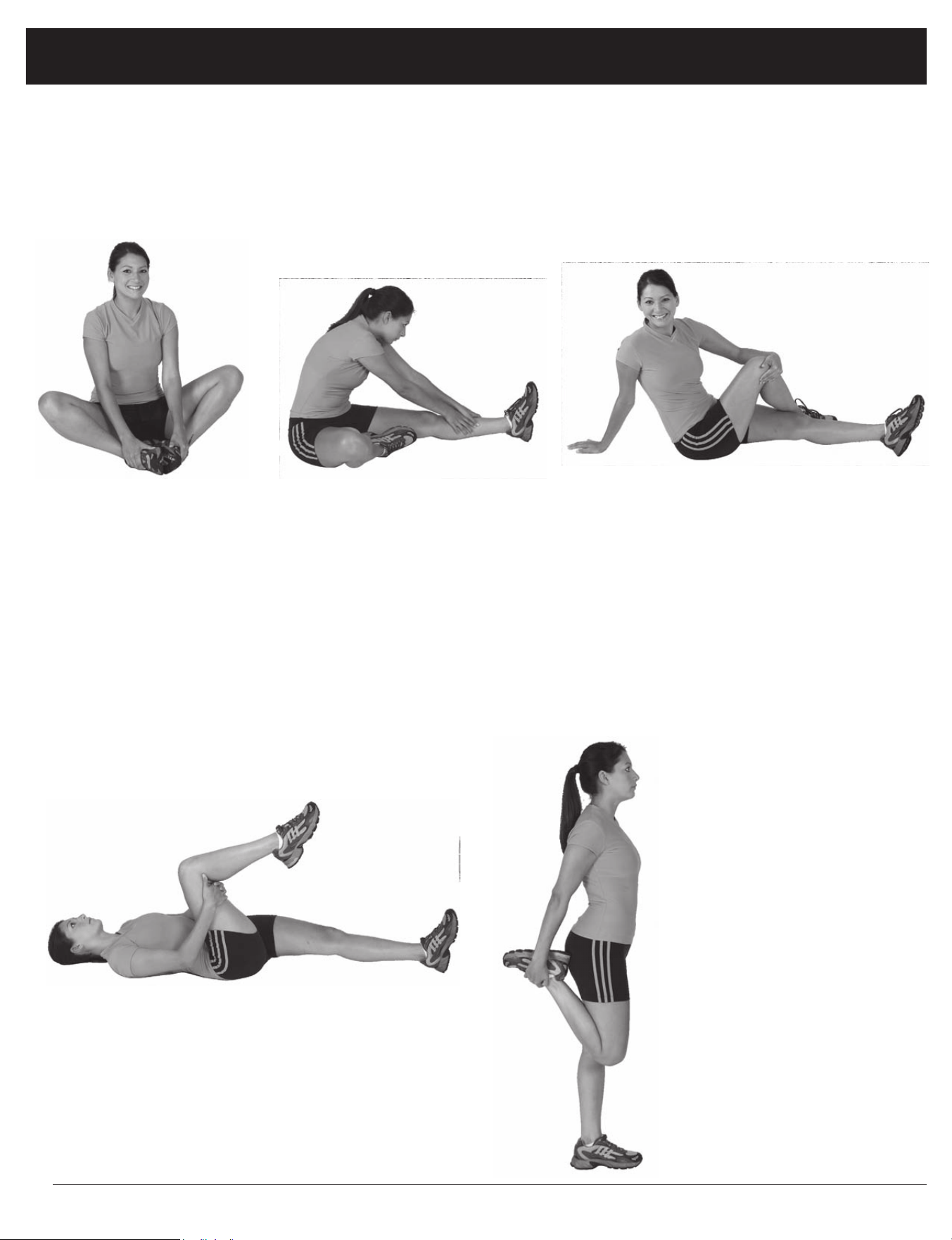
Warm-Up Instructions
Groin Stretch
1. Sit with your knees flexed
and soles of feet together.
2. Hold your ankles and bend
at your hips (keep your
back straight) as you press
your knees toward the
floor with your elbows.
Hamstring Stretch
1. Sit with your left leg extended and bend your right
leg at the knee as you place the sole of your right foot
against the inner thigh of your extended leg.
2. Flex the foot of your extended leg (toes pointed
toward ceiling) and gently bend forward from your
hips; keep your back straight.
3. Reach your hands on your extended leg as far as pos-
sible and then switch legs and repeat.
Trunk Twister
1. Sit with your leg extended and
bend your right knee as you cross
your right leg over your left leg.
Your right foot should be flat on the
floor alongside your left knee.
2. Place your left arm on the outside
of your right leg and pull against
that leg while twisting your trunk
as far as possible to the right. Place
your right hand on the floor behind
your buttocks. Reverse leg posi-
tions and repeat.
Hip Stretch
1. Lie on your back and raise your right leg as you clasp both hands
under the back of the knee. Keep your left leg straight.
2. Gently pull your right leg toward your trunk without raising your
upper body. Switch leg positions and repeat.
The following flexibility exercises are provided to you as a means to prevent injury while you are exercising. A
proper warm-up routine decreases the chance of injuring your muscles while you are exercising. Please take the
time to do these flexibility exercises before and after each time you exercise.
Quadriceps Stretch
1. Stand on your left leg and hold onto
a support with your left hand.
2. Flex your right leg behind you, grasp
your ankle or foot with your right
hand and pull your foot toward your
buttocks. Keep your back straight
and right knee pointed down. Repeat
on the other leg.
Page 22
BRT 3858
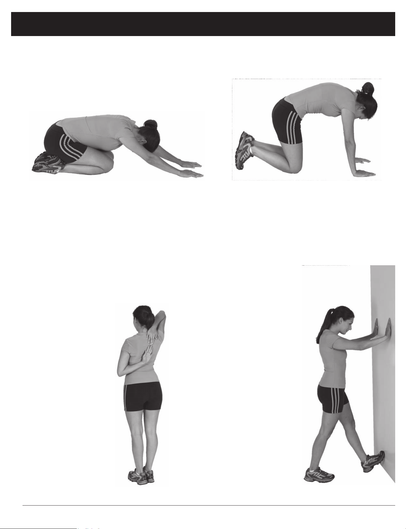
Trunk Flexion, Prone
1. Assume the depicted position on your hands and knees. Stretch your hands out in front of you and then slowly start to pull
them back in toward your body as you tuck your chin and arch your back upward.
2. Return to the starting position slowly.
Shoulder Stretch
1. Bring your right hand over
your right shoulder to the
upper back and bring your
left hand under your left
shoulder to the upper back.
2. Try to reach your finger-
tips. If you are not able to
reach your fingertips, use
a towel as an extension of
your hands and gently pull
one hand toward the other.
Reverse arm positions and
repeat.
Calf Stretch
1. Place both hands against
a wall to aid your balance.
Press the ball of your left foot
against the wall and keep the
heel of the same foot rested
on the floor (make sure your
left knee is bent).
2. Slowly start to straighten your
left knee and you will feel
the muscles in your left calf
stretch. Switch leg positions
and repeat.
Warm-Up Instructions
Page 23
BRT 3858

Proof of purchase
Model Number BRT 3858
version:04-12-2019

This page intentionally left blank

This page intentionally left blank

Body Flex Sports, Inc. • 21717 Ferrero Parkway, Walnut, CA 91789 • Telephone: (888) 266 - 6789 • Email: info@bodyflexsports.com
Made In China