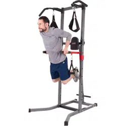
VKR
1700
B o d y C h a m p P o w e r T o w e r
OWNER’S MANUAL
* This item is for consumer use only and it is not meant for commercial use.
General Information
VKR1700 Power Tower Page 1
Warranty
Body Flex Sports warrants your product for
a period of 1 year for the frame and 90 days
on all parts if the item is used for the intended
purpose, properly maintained and not used
commercially. Any alterations or incorrect
assembly of the product will void this warranty.
Proof of purchase must be presented for any
warranty validation (no exceptions). This
warranty applies to the original purchaser only
and is not transferable.
This warranty does not cover abuse or defects
caused during use, storage or assembly.
During the warranty period, Body Flex Sports
reserves the right to:
a). provide replacement parts to the
purchaser in an effort to repair the item.
b). repair the product returned to our
warehouse (at the purchaser’s cost).
c). replace the product if neither of the two
previously mentioned actions effect repair.
This warranty does not cover normal wear and
tear on upholstery.
Questions
If you have any questions concerning the
assembly of your item or if any parts are
missing, please DO NOT RETURN THE
ITEM TO THE STORE OR CONTACT THE
RETAILER. Our dedicated customer service
staff can help you with any questions you may
have regarding the assembly of this unit and
can also mail you replacement parts.
Customer Support
Customer Support is open 9:00 a.m. to 5:00
p.m. (Pacic Time) Monday through Friday.
Please contact us by any of the following
means.
Body Flex Sports, Inc.
21717 Ferrero Parkway, Walnut, CA 91789
Telephone: (888) 266 - 6789
Fax: (909) 598 - 6707
Email: info@bodyexsports.com
Safety
Before you undertake any exercise program,
please be sure to consult with your doctor.
Frequent strenuous exercise should be
approved by your doctor and proper use
of your product is essential. Please read
this manual carefully before commencing
the assembly of your product or starting to
exercise.
• Please keep all children away from this item
when in use. Do not allow children to climb or
play on them when they are not in use.
• Supervise teenagers while they use this unit.
• For your own safety, always ensure that there
is at least 4 feet of free space in all directions
around your product while you are exercising.
• Regularly check to see that all nuts, bolts and
ttings are securely tightened. Periodically
check all moving parts for obvious signs of
wear or damage.
• Clean only with a damp cloth, do not use
solvent cleaners. If you are in any doubt, do
not use your product; contact CUSTOMER
SUPPORT.
• Before use, always ensure that your product
is positioned on a solid, at surface. If
necessary, use a rubber mat underneath to
reduce the possibility of slipping.
• Always wear appropriate clothing and
footwear such as training shoes when
exercising. Do not wear loose clothing that
could become caught in moving parts during
exercise.
• Do not use this unit if it is not functioning
properly or if it is not fully assembled.
• Do not use this unit for commercial purposes.
Storage and Use
Your product is intended for use in clean
dry conditions. You should avoid storage in
excessively cold or damp places as this may
lead to corrosion and other related problems.
VKR1700 Power Tower Page 2
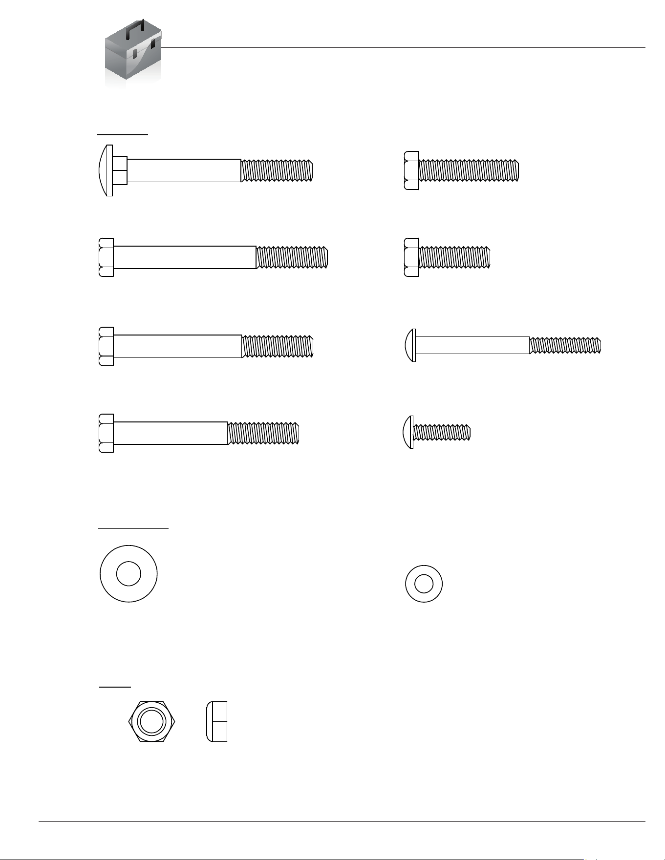
Hardware List
The following hardware and tools are used to assemble your unit.
Please take a moment to familiarize yourself with these items.
BOLT
Washer
Nut
#15 Carriage Bolt (M8x70 mm) [4 pieces]
#19 Hex Bolt (M8x35 mm) [2 pieces]
#16 Hex Bolt (M8x75 mm) [14 pieces]
#20 Hex Bolt (M8x25 mm) [6 pieces]
#17 Hex Bolt (M8x70 mm) [4 pieces]
#21 Screw (M6x65 mm) [4 pieces]
#18 Hex Bolt (M8x65 mm) [4 pieces]
#22 Screw (M6x20 mm) [4 pieces]
#23 Washer (M8) [8 pieces]
#24 Washer (M6) [8 pieces]
#25 Nylon Lock Nut (M8) [24 pieces]

VKR1700 Power Tower Page 3
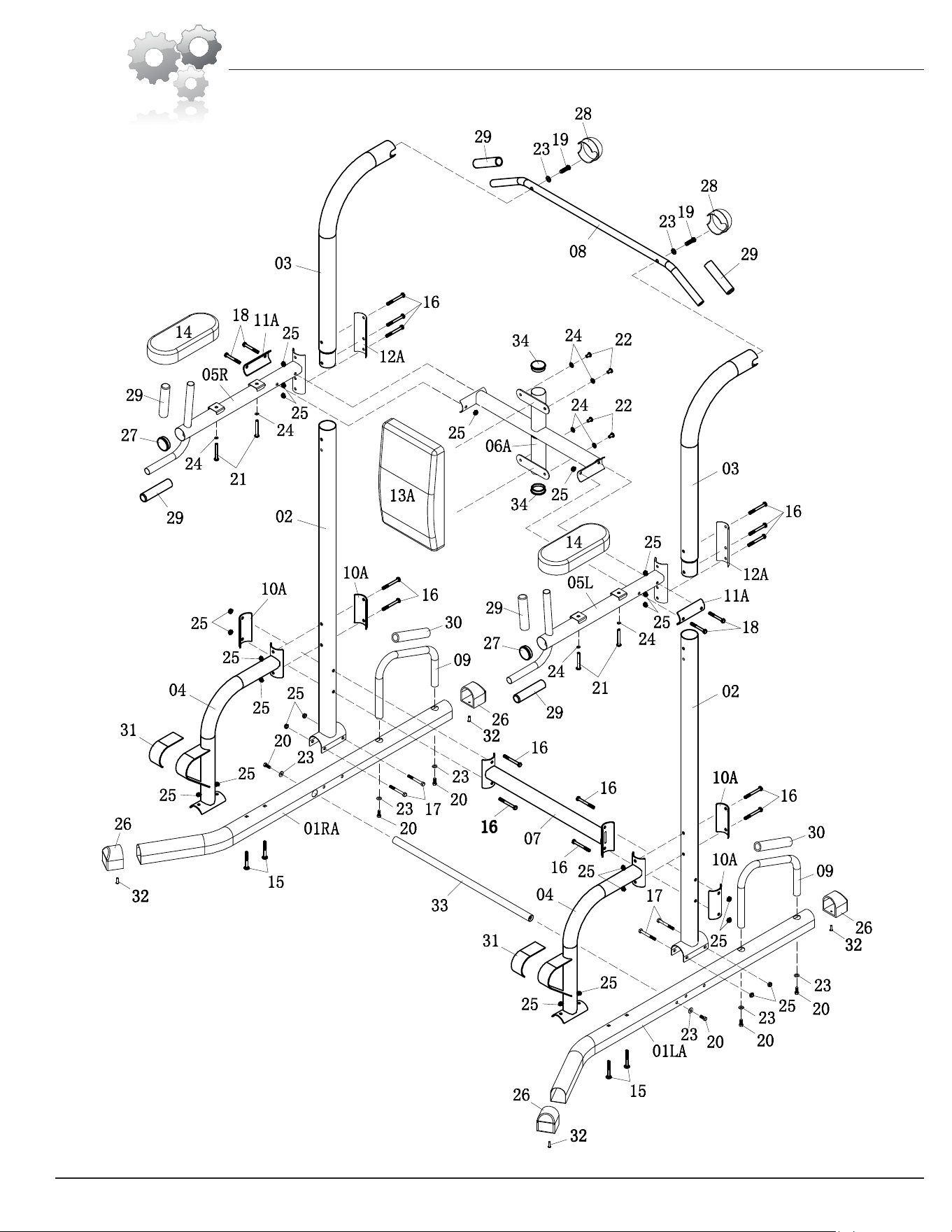
Parts Listing
The following parts list describes all of the parts illustrated on the
exploded diagram on the following page. Please note, most of
these parts are already pre-assembled on your unit.
# Description
01LA/01RA Stabilizer
02 Upright Base
03 Upright
04 Support
05L/05R Dip Arm
Top C
rossbar
07 Bottom Crossbar
08 Pull
Up Bar
09 Push Up Bar
Support Plate A
Supp
ort Plate B
Suppo
rt Plate C
Backre
st
14 Arm Pad
15 Carriage Bolt (M8x70 mm)
16 Hex Bolt (M8x75 mm)
17 Hex Bolt (M8x70 mm)
18 Hex Bolt (M8x65 mm)
19 Hex Bolt (M8x35 mm)
20 Hex Bolt (M8x25 mm)
21 Screw (M6x65 mm)
22 Screw (M6x20 mm)
23 Washer (M8)
24 Washer (M6)
25 Nylon Nut (M8)
26 Outer End Cap
27 End Cap (φ50xt1.5 mm)
28 End Cap (φ60 mm)
29 Handgrip
30 Foam
31 Emery Cloth
32 Screw (M5x20 mm)
33
Support Crossbar
34
End Cap (φ50xt1.2 mm)
06A
10A
11A
12A
13A
VKR1700 Power Tower Page 4
Exploded Diagram
VKR1700 Power Tower
Assembly Instructions
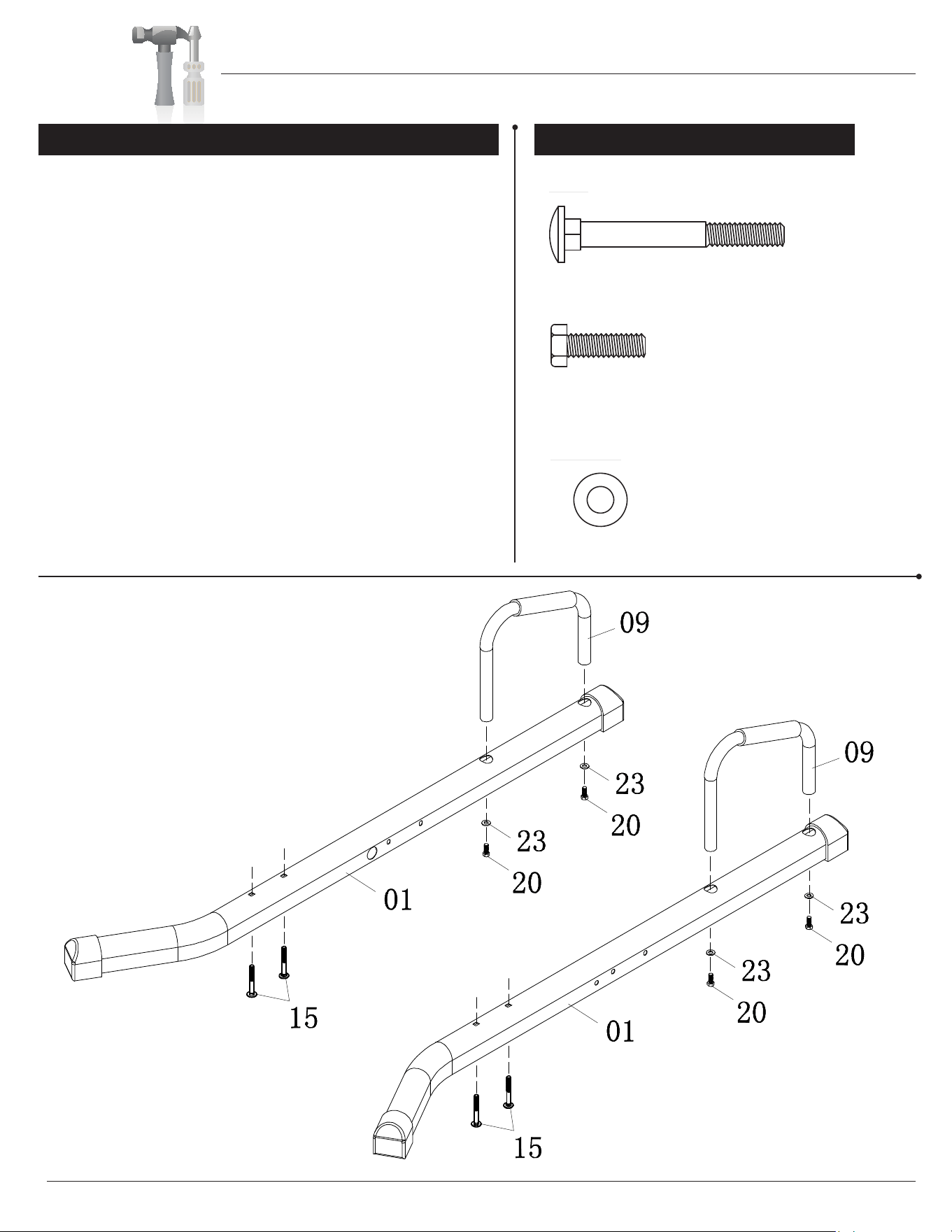
A s s e m b l y S t e p 1
Hardware Required
#15 Carriage Bolt (M8x70 mm)
[4 pieces]
#20 Hex Bolt (M8x25 mm)
[4 pieces]
#23 Washer (M8) [4 pieces]
Washer
Bolt
Page 5
B. Insert two Carriage Bolts (#15) through the base of the Left
Stabilizer (#01LA).
A. With the help of an assistant, attach the Push Up Bar (#09) to
the Left Stabilizer (#01LA) as shown and secure it using two Washers
(#23) and two Hex Bolts (#20).
C. Repeat this process on the opposite
side.
Note:This step is a preparation for Assembly Step 4, as it will be
heavy to lift the unit in a later process.
RA
LA
VKR1700 Power Tower
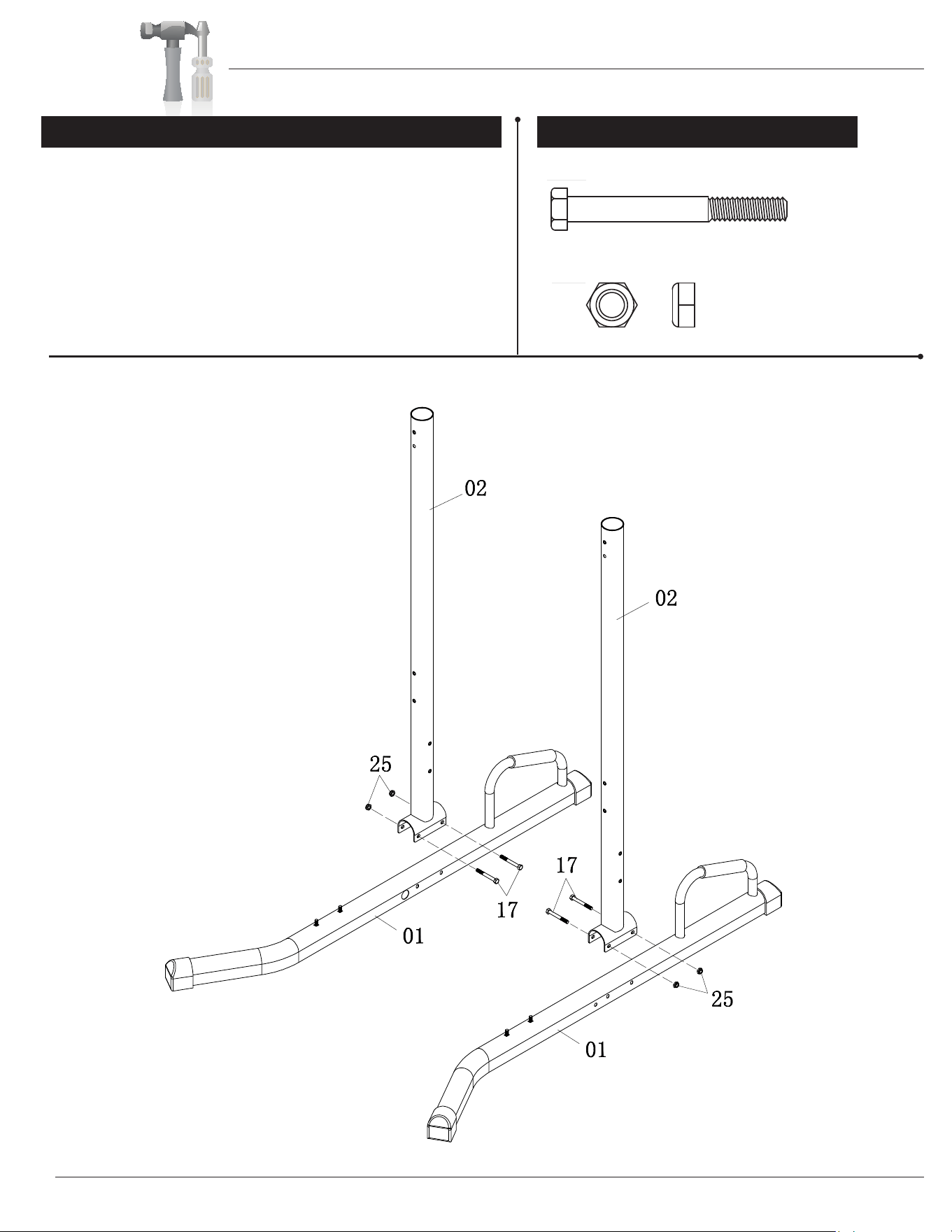
Assembly Instructions
With the help of an assistant, attach the Upright Base (#02) to
the Left Stabilizer (#01LA) as shown, secure it with two Hex Bolts
(#17) and two Nylon Nuts (#25). Repeat this process on the
opposite side.
A s s e m b l y S t e p 2
Hardware Required
#17 Hex Bolt (M8x70 mm) [4 pieces]
#25 Nylon Nut (M8) [4 pieces]
Nut
Bolt
Page 6
RA
LA
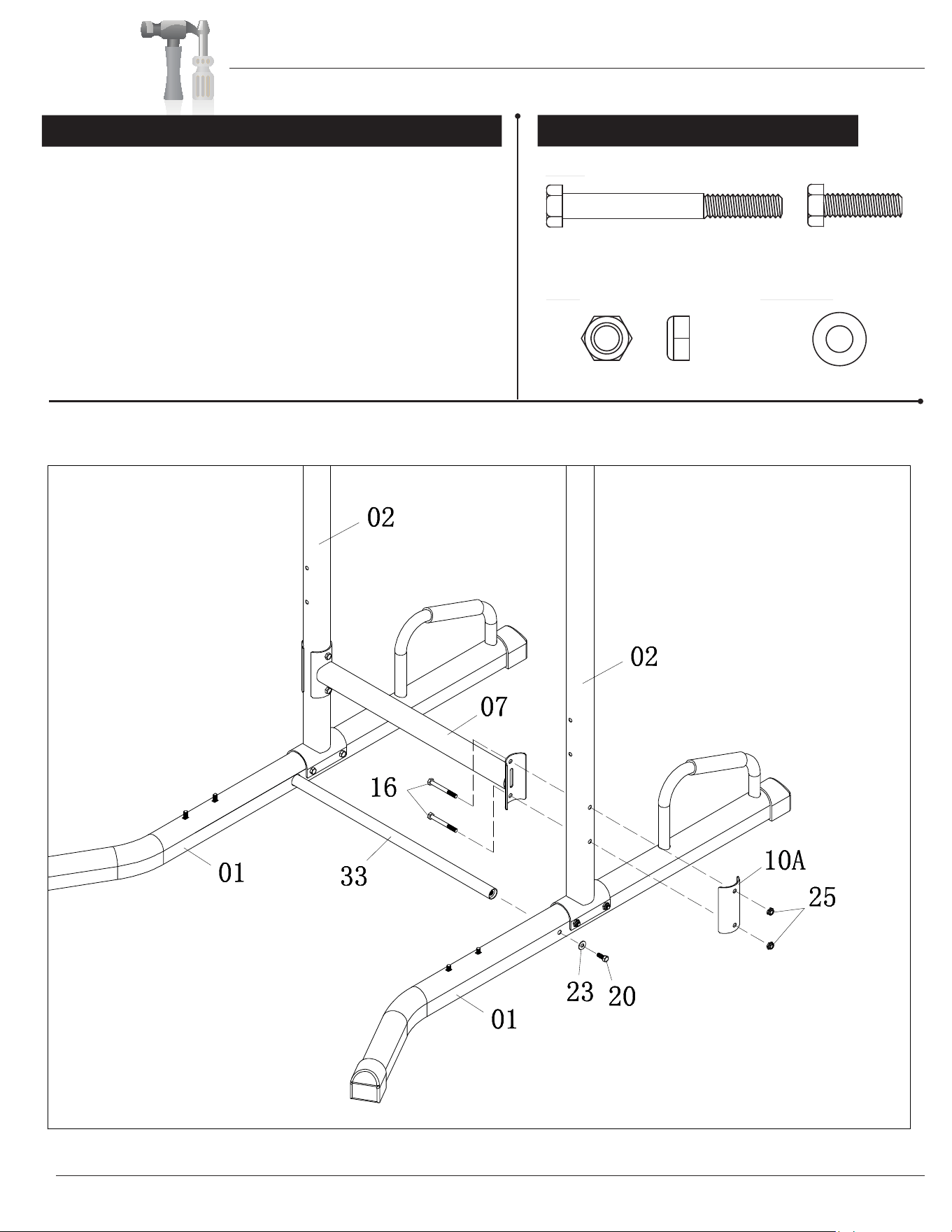
VKR1700 Power Tower
Assembly Instructions
Insert the Support Crossbar (#33) in the hole located on the
inside of Right Stabilizer (#01RA), secure it with one Washer
(#23) and one Hex Bolt (#20).
Attach the Bottom Crossbar (#07) to the Right Upright Base
(#02) by inserting two Hex Bolts (#16) through the Bottom
Crossbar (#07) and then into the Upright Base (#02) followed
by one Support Plate A (#10A). Then secure it with two Nylon
Nuts (#25).
Repeat this process on the opposite side.
A s s e m b l y S t e p 3
Hardware Required
Page 7
#16 Hex Bolt (M8x75 mm)
[4 pieces]
#25 Nylon Nut (M8) [4 pieces]
Nut
Bolt
#20 Hex Bolt (M8x25 mm)
[2 pieces]
#23 Washer (M8) [2 pieces]
Washer
RA
LA
VKR1700 Power Tower
Assembly Instructions
Page 8
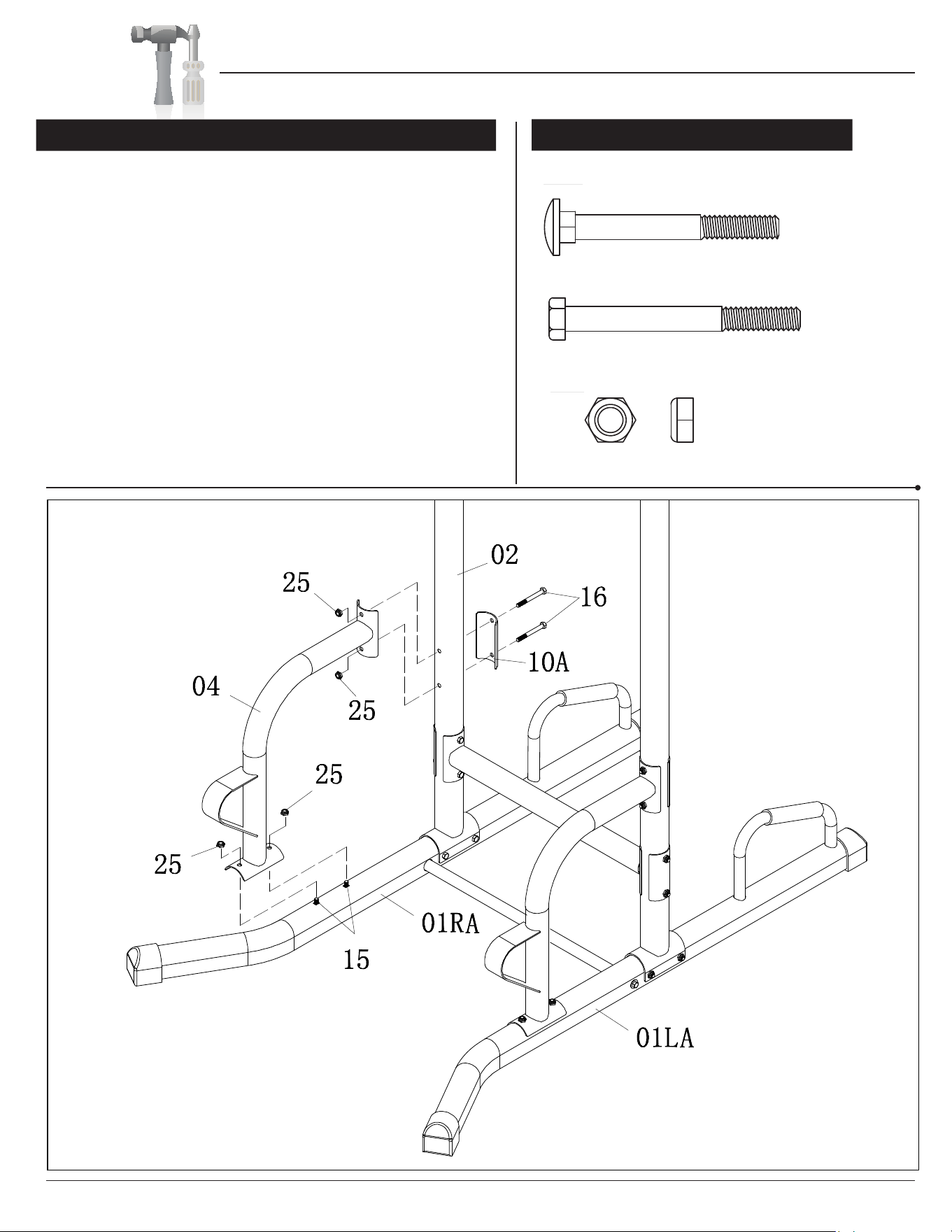
A s s e m b l y S t e p 4
Hardware Required
Connect the upper part of the Support (#04) to the Upright
Base (#02) by inserting two Hex Bolts (#16), through the Support
plate A (#10A) and then through the Upright Base (#02) followed
by the Support (#04) and secure it with two Nylon Nuts (#25).
Attach the lower part of the Support (#04) to the two Carriage
Bolts (#15) which you inserted into the two Stabilizers (#01A)
during the first step. At this point hand tighten the Nylon Nuts
(#25) on the lower portion as it may be difficult to align the holes
for the upper portion.
At this point secure the Nylon Nuts (#25) that were hand tighten in
the lower portion. Repeat this process on the other side.
#15 Carriage Bolt (M8x70 mm) [4 pieces]
#16 Hex Bolt (M8x75 mm) [4 pieces]
#25 Nylon Nut (M8) [8 pieces]
Nut
Bolt
* * * * * * * * * * * * * * * * * * * * * * * * * * * * *
* * * * * * * * * * * * * * * * * * * * * * * * * * * *
*
*
*
*
*
*
*
*
*
*
*
*
*
*
*
VKR1700 Power Tower P
Assembly Instructions
age 9
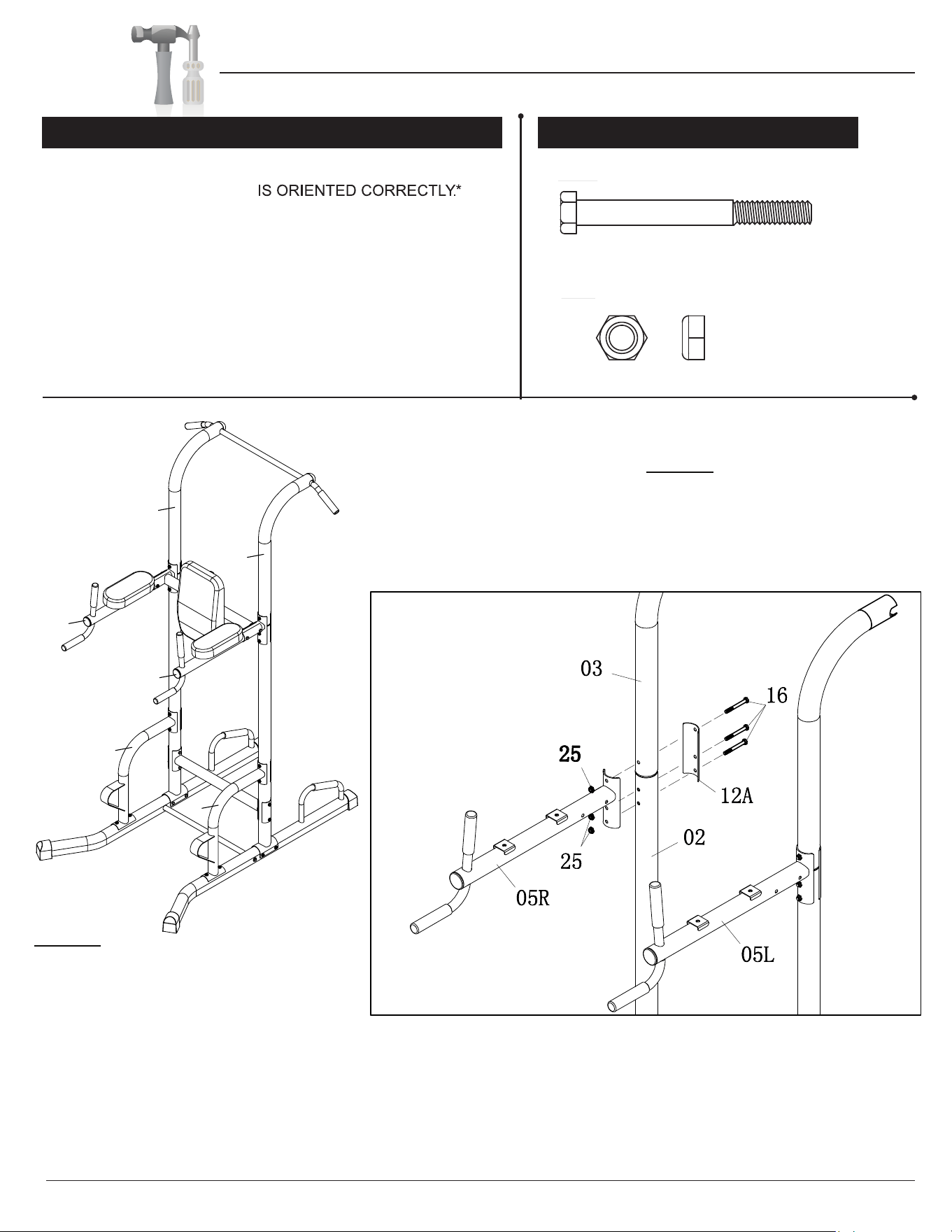
A.
A s s e m b l y S t e p 5
Hardware Required
Insert the Upright (#03) into the Upright Base (#02) ENSURE
THAT THE
UPRIGHT (#03)
B. Insert three Hex Bolts (#16 ) through the Support Plate C
(#12A) and then through the Upright (#03) and Upright
Base (#02) followed by the Dip Arm (#05R). Hand tighten
them with three Nylon Nuts (#25).
C. Repeat this process on the opposite side (left side).
MAKE SURE THAT
THE CURVED SIDE
OF THE UPRIGHT
(#03)
ARCHES AWAY
FROM
#16 Hex Bolt (M8x75 mm) [6 pieces]
#25 Nylon Nut (M8) [6 pieces]
Nut
Bolt
Please refer to NOTE #1 and NOTE #2 on the
illustration!
MAKE SURE THE
DIP ARMS (#05) ARE
FACING THE SAME
DIRECTION AS THE
SUPPORT (#04).
NOTE #1:
NOTE #2:
THE TWO DIP ARMS (#05).
04
04
03
03
05R
05L
VKR1700 Power Tower
Assembly Instructions
Page 10
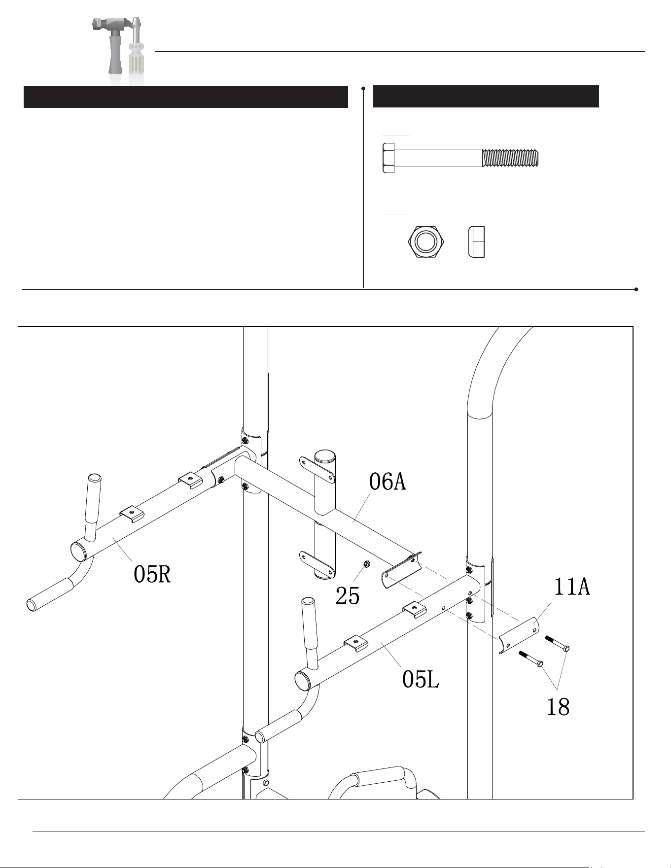
A.
A s s e m b l y S t e p 6
Hardware Required
Slide the Top Crossbar (#06A) between the two Dip Arms
(#05R & #05L). Insert two Hex Bolts (#18) through the
Support Plate B (#11A). Screw one of the Hex Bolts (#18)
through the Dip Arm (#05L) and secure it directly into the Top
Cross Bar (#06A). Screw the other Hex Bolt (#18) into the
Dip Arm (#05L) followed by the Top Cross Bar (#06A) and
then secure using one Nylon Nut (#25).
B. Repeat this process on the opposite side.
#18 Hex Bolt (M8x65 mm) [4 pieces]
#25 Nylon Nut (M8) [2 pieces]
Nut
Bolt
VKR1700 Power Tower P
Assembly Instructions
age 11
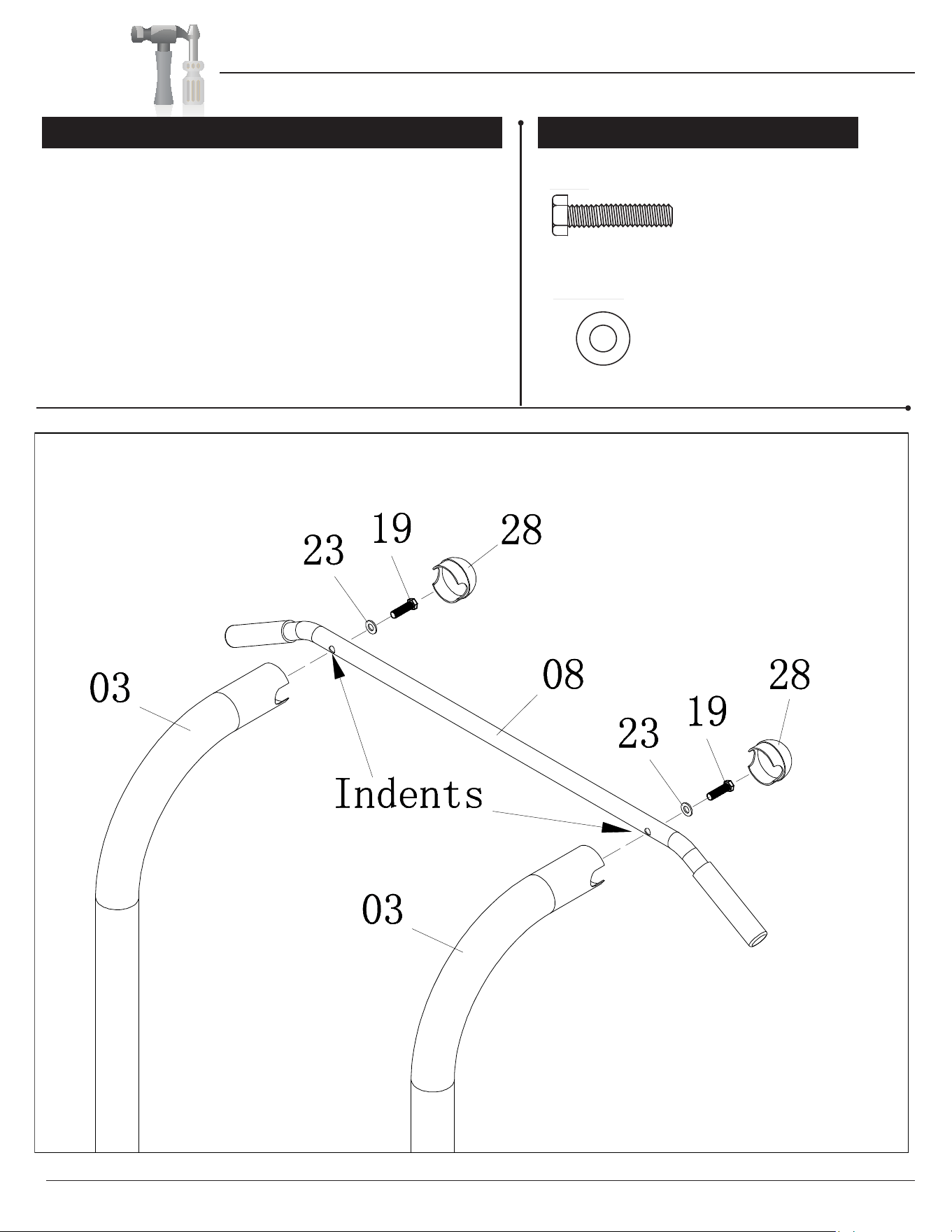
Attach the Pull up Bar (#08) to the two Uprights (#03) by inserting
two Hex Bolts (#19) through two Washers (#23), Pull Up Bar
(#08) and then securing them into the two Uprights (#03).
MAKE SURE THE TWO INDENTATIONS ON THE PULL
UP BAR (#08) ARE FACING TOWARD THE UPRIGHTS (#03).
Slide two End Caps (#28) on top of the assembly.
A s s e m b l y S t e p 7
Hardware Required
#19 Hex Bolt (M8x35 mm) [2 pieces]
#23 Washer (M8) [2 pieces]
Washer
Bolt
VKR1700 Power Tower
Assembly Instructions
Page 12
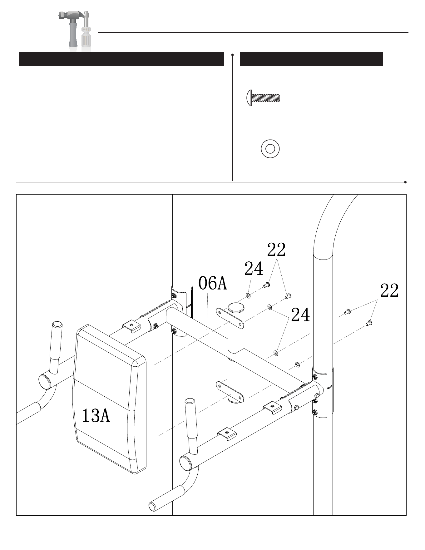
Attach the Backrest (#13A) to the Top Crossbar (#06A) using a
total of four Screws (#22) and four Washers (#24). DO NOT
OVER TIGHTEN THE SCREWS AS THIS MAY STRIP THE
THREAD OR CRACK THE WOOD IN THE BACKREST (#13A).
A s s e m b l y S t e p 8
Hardware Required
#22 Screw (M6x20 mm) [4 pieces]
#24 Washer (M6) [4 pieces]
Washer
Bolt
VKR1700 Power Tower
Assembly Instructions
Page 13
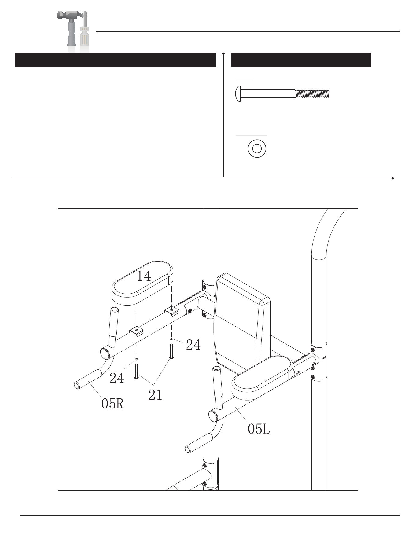
A. Insert two Screws (#21) and two Washers (#24) through the
bottom of the Right Dip Arm (#05R) and secure the Arm Pad
(#14) to the Right Dip Arm (#05R). DO NOT OVERTIGHTEN
AS THIS MAY STRIP THE THREAD OR CRACK THE WOOD
ARM PAD (#14).
B. Repeat this process on the opposite side.
Now tighten all the Bolts.
IN THE
The assembly process is complete.
A s s e m b l y S t e p 9
Hardware Required
#21 Screw (M6x65 mm) [4 pieces]
#24 Washer (M6) [4 pieces]
Washer
Bolt
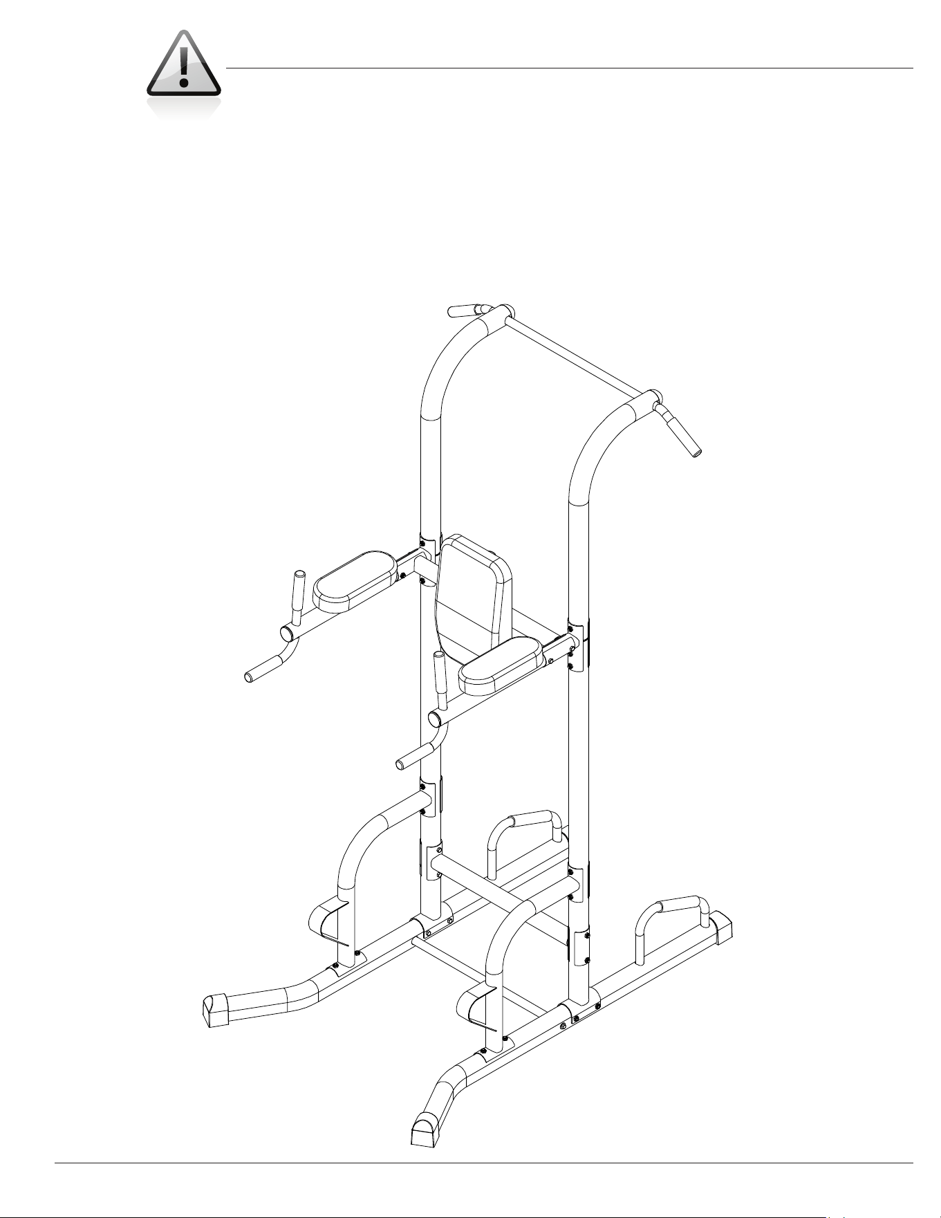
VKR1700 Power Tower
Safety Instructions
Page 14
• Make sure all bolts are tightened.
• Check for loose parts and components
• Check to see if there are any tears or bends in the welding or metal.
• Be sure that all adjustment locking devices and safety devices are
properly engaged prior to use!
Thanks for choosing
"ODY&LEX3PORTS)NC
&ERRERO0ARKWAY
7ALNUT#!
0HONE
&AX
%MAILINFO BODYFLEXSPORTSCOM
VKR 1700
Store Location:
Version: 8-25
-09