
DISHDRAWER
TM
DISHWASHER
INSTALLATION GUIDE
592364C 07.25NZ AU UK IE SG ASIA
Components required 3
Accessing your product specifications 4
Prior to installation 6
Prepare dishwasher 10
Install dishwasher 18
Prepare custom panel 19
Complete dishwasher installation 25
Check panel face alignment 32
Install services 34
Installer checklist 41

INTEGRATED DISHDRAWER
TM
DISHWASHER
DD60STX6I1, DD60STX6HI1

3
COMPONENTS REQUIRED
TOOLS
PARTS
Supplied and required
F 4x Side mounting brackets
F 1x Moisture protection tape
F 1x Door bracket kits
F 16x 16mm Crosshead screws
F 2x 38mm chassis feet fixing screws
and washers
Supplied
F 4x Spacer sets
F 2x 0.5mm Shims
F 4x .75mm Shims
F 1x Drain hose support
F 1x Drain hose joiner
F 1x Wire clip
F 1x Clamp
F 1x External venting kit
Not supplied
F Box cutter
F Crosshead screwdriver
F Flat blade screw driver
F Drill
F 1x 13mm Drill bit
F 1x 2.5mm Drill bit
F Level
F Pliers
F Pencil
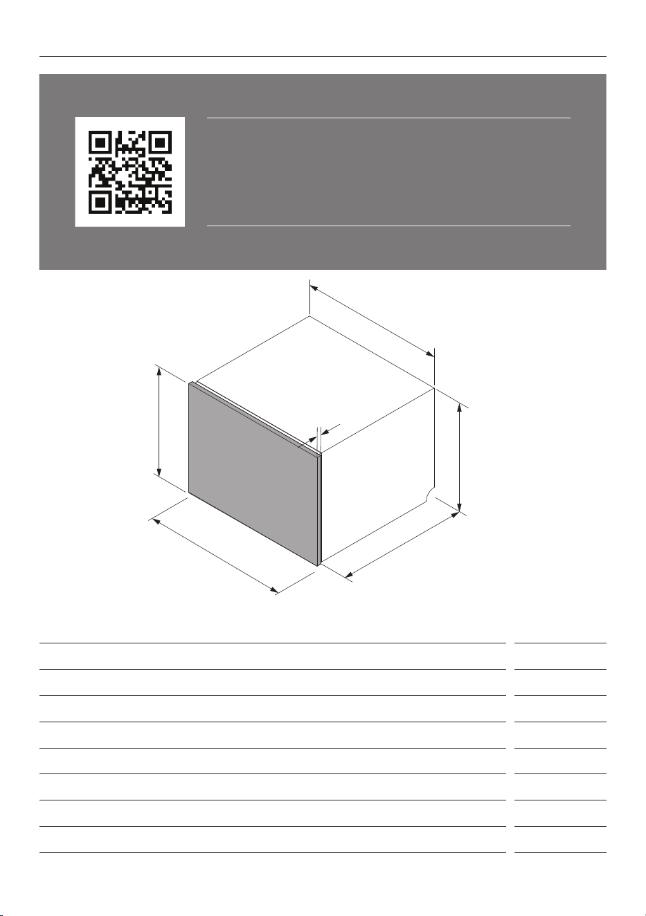
To access installation videos, scan the QR code or go to: https://www.
fisherpaykel.com/nz/dishdrawer-installation-videos
The videos provide an overview of the DishDrawer™ installation and are
not intended to be used as a standalone guide.
Installation should be undertaken by a Fisher & Paykel trained and
supported service technician or qualified person.
4
ACCESSING YOUR PRODUCT SPECIFICATIONS
Product and Panel Dimensions mm
A Chassis height
455
B Chassis width 599
C Chassis depth 553
D Panel minimum height
452
E Panel minimum width
596
F Panel thickness
16-20
Maximum panel downward extension 50
Note: A 2mm clearance gap is required between the dishwasher drawer panel and surrounding cabinet
panels.
A
B
C
D
E
F
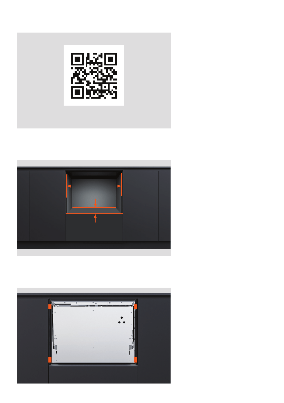
For full product, cabinetry and service specifications, refer
to the Planning Guide. To access the Planning Guide, scan
the QR code or visit fisherpaykel.com/specify. Search by
appliance type, product name or model code.
For installation support please contact the Fisher & Paykel
design support team at designsupport@fisherpaykel.com
5
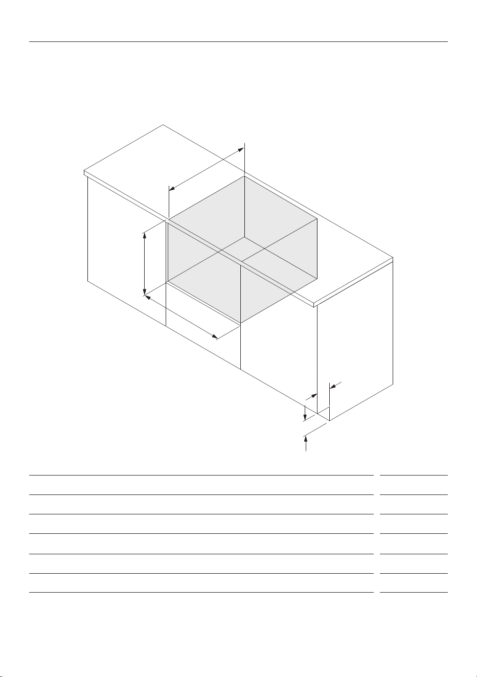
ACCESSING YOUR PRODUCT SPECIFICATIONS
Cavity Dimensions mm
A Cavity minimum height
457
B Cavity minimum width
600
C Cavity minimum depth* 578
D Minimum cabinet toe kick height** 100
E Minimum cabinet toe kick depth** 60
*Guide assumes 18mm door panels **When venting through toe kick
A
B
C
D
Ensure there is a small gap between the custom panel and any cabinetry behind it to
maintain a proper seal in the dishwasher.
This prevents moisture escape and condensation, which can damage the custom panel.
E
6
PRIOR TO INSTALLATION
1. Refer to the Planning Guide
for cabinetry, cavity, panel and
service specifications.
fisherpaykel.com/specify
2. Ensure the cabinet meets the
minimum cavity specifications
required.
Check that the cabinet sides
are square.
3. If the cavity is too wide, add
material to the sides to allow
the dishwasher to be secured.
See the planning guide for
details.
7
4. Check that the cabinet is
level.
PRIOR TO INSTALLATION
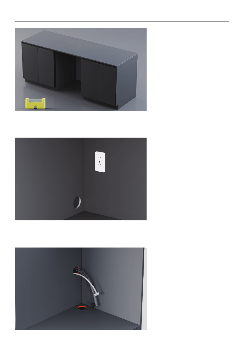
5. The power plug should be
accessible after installation for
maintenance.
6. Service holes can be routed
from the dishwasher into the
adjacent cavity.
8
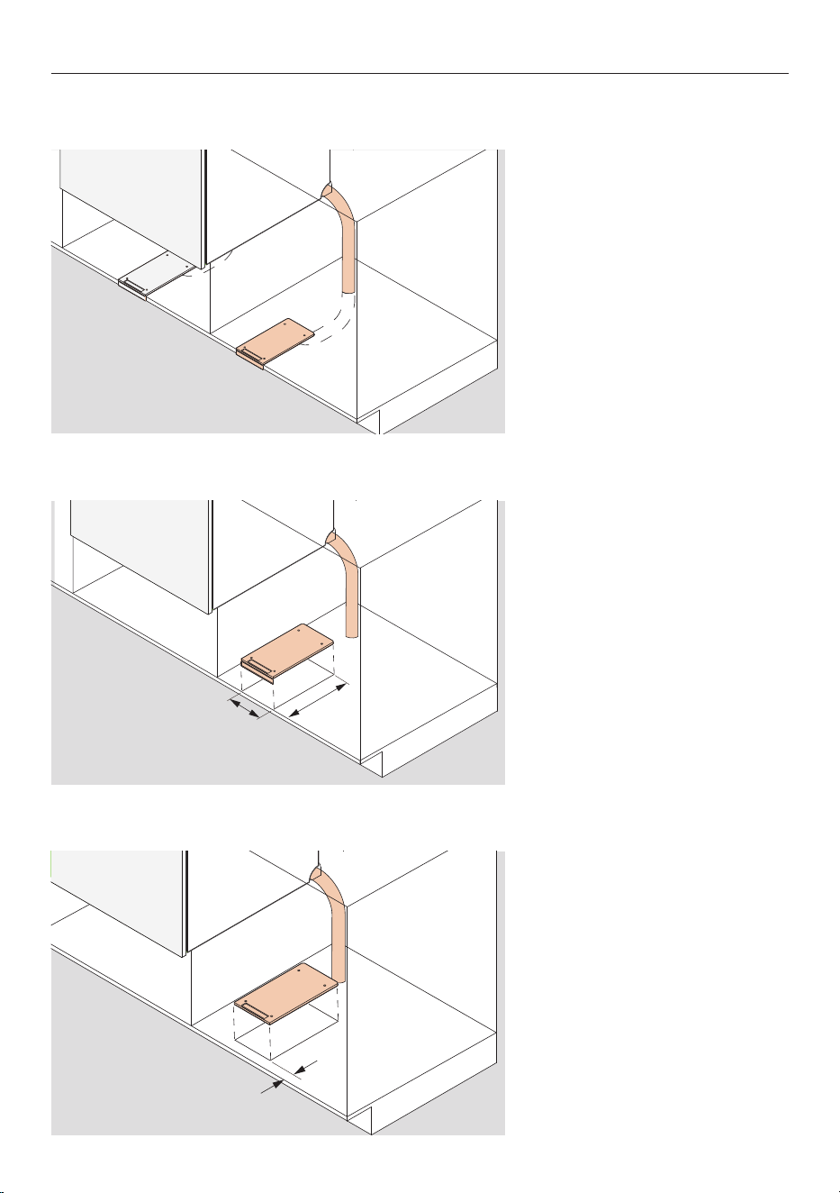
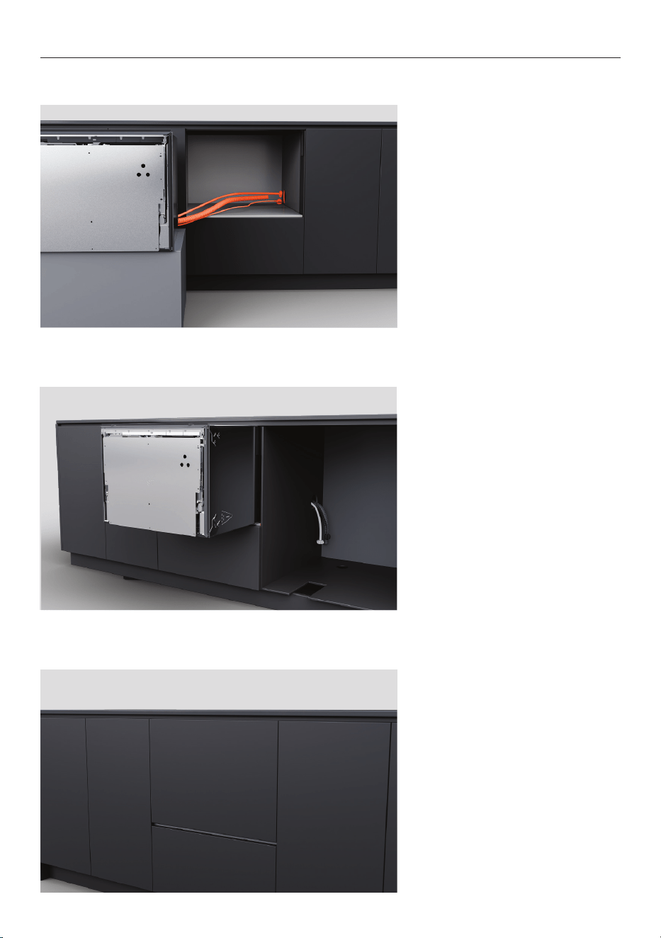
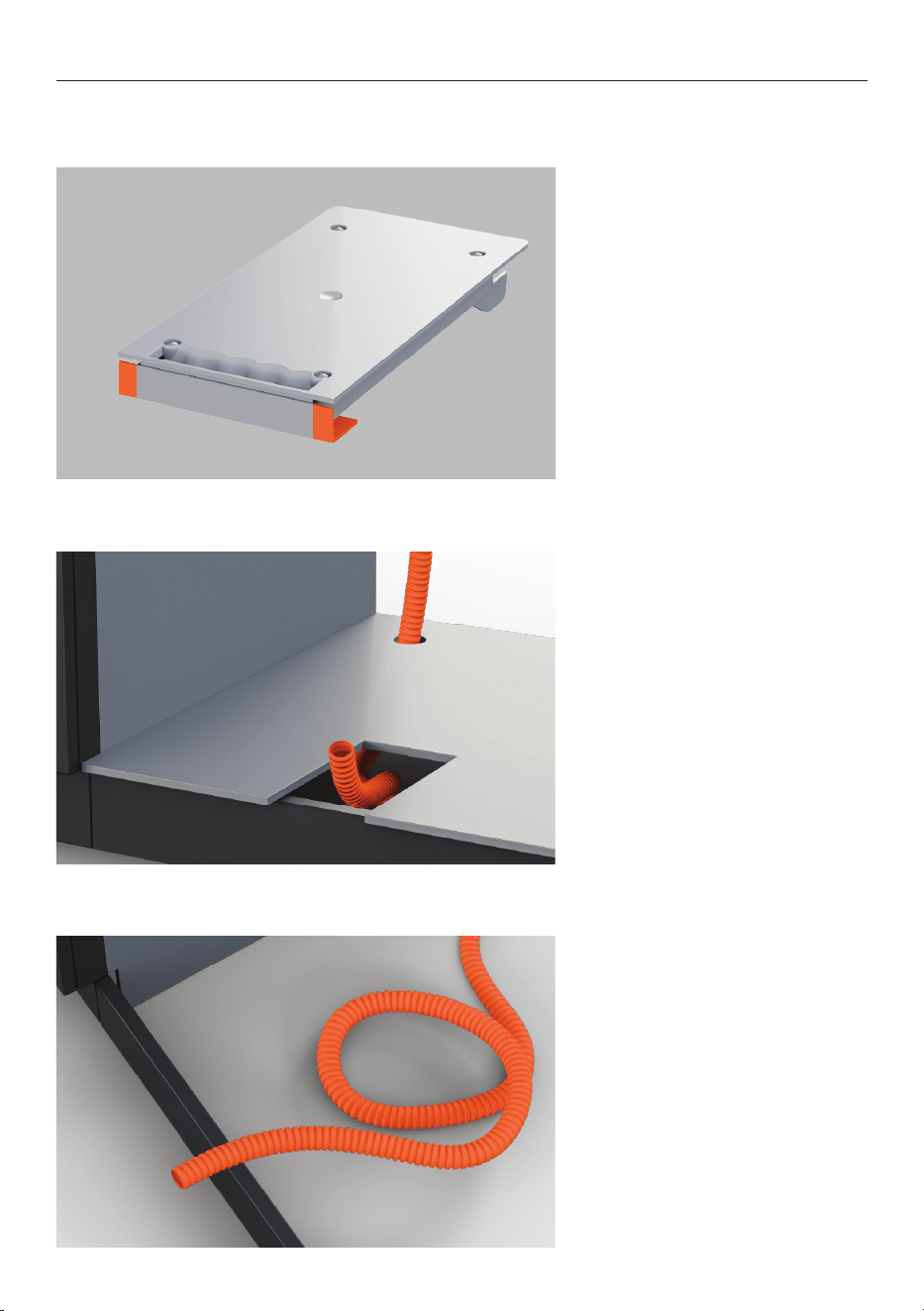
1. The vent hose can be routed
through to the adjacent cabinet
and into the toe kick.
Alternatively, it can be routed
under the dishwasher into the
toe kick.
PRIOR TO INSTALLATION - SERVICES
2. The vent duct cut out is
100mm x 220mm.
3. Framed cabinetry:
The cut out should be placed
25mm back from the frame.
If routed through the cabinet toe kick, vent ducts require a minimum toe kick height of
100mm and depth of 60mm.
100mm
220mm
25mm
9
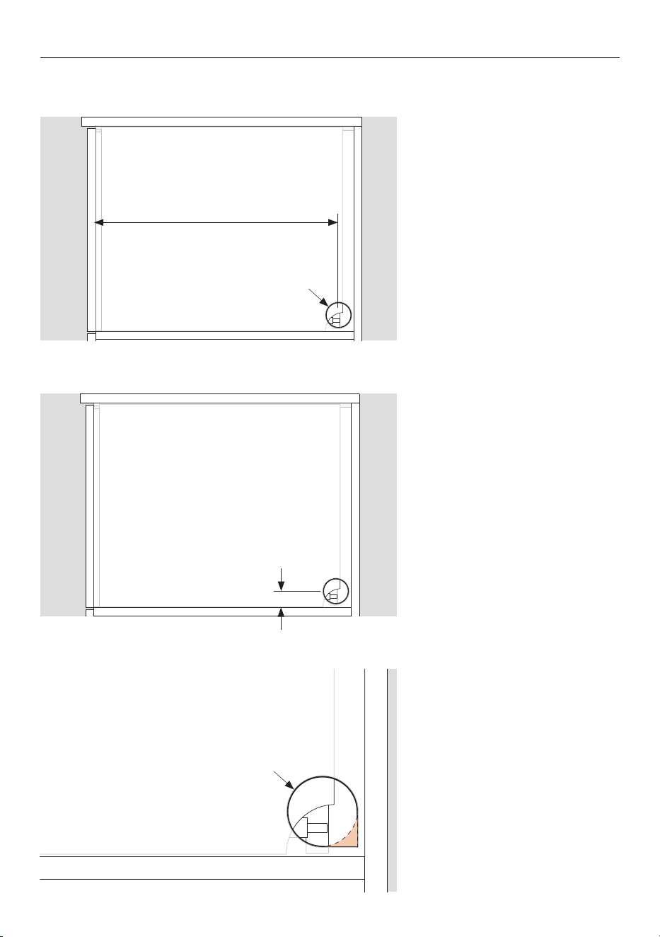
PRIOR TO INSTALLATION - SERVICES
1. A minimum 57mm diameter
service hole is required in the
cabinet side.
The center of the hole should
be a minimum of 538mm from
the front of the chassis.
Refer to the Planning Guide at fisherpaykel.com for service options.
2. The center of the hole should
be a maximum of 38mm from
the shelf.
538mm
57mm dia
3. If the vent hose is routed
through the service hole, cut
out the back corner.
38mm
57mm dia
10
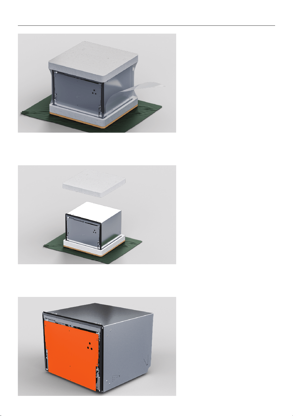
UNPACK ALL PRODUCTS
1. Remove the plastic wrap.
2. Remove the top packaging.
Leave the base on to protect
the floor surface while moving
the dishwasher.
3. Do not remove door
bracket from the front of the
dishwasher.
11
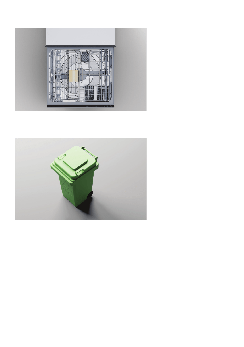
UNPACK ALL PRODUCTS
5. Dispose of packaging
responsibly.
4. Peel the tape from the top
drawer and remove accessories
and installation packages from
the tub.
Close the drawer and re-apply
the tape.
12
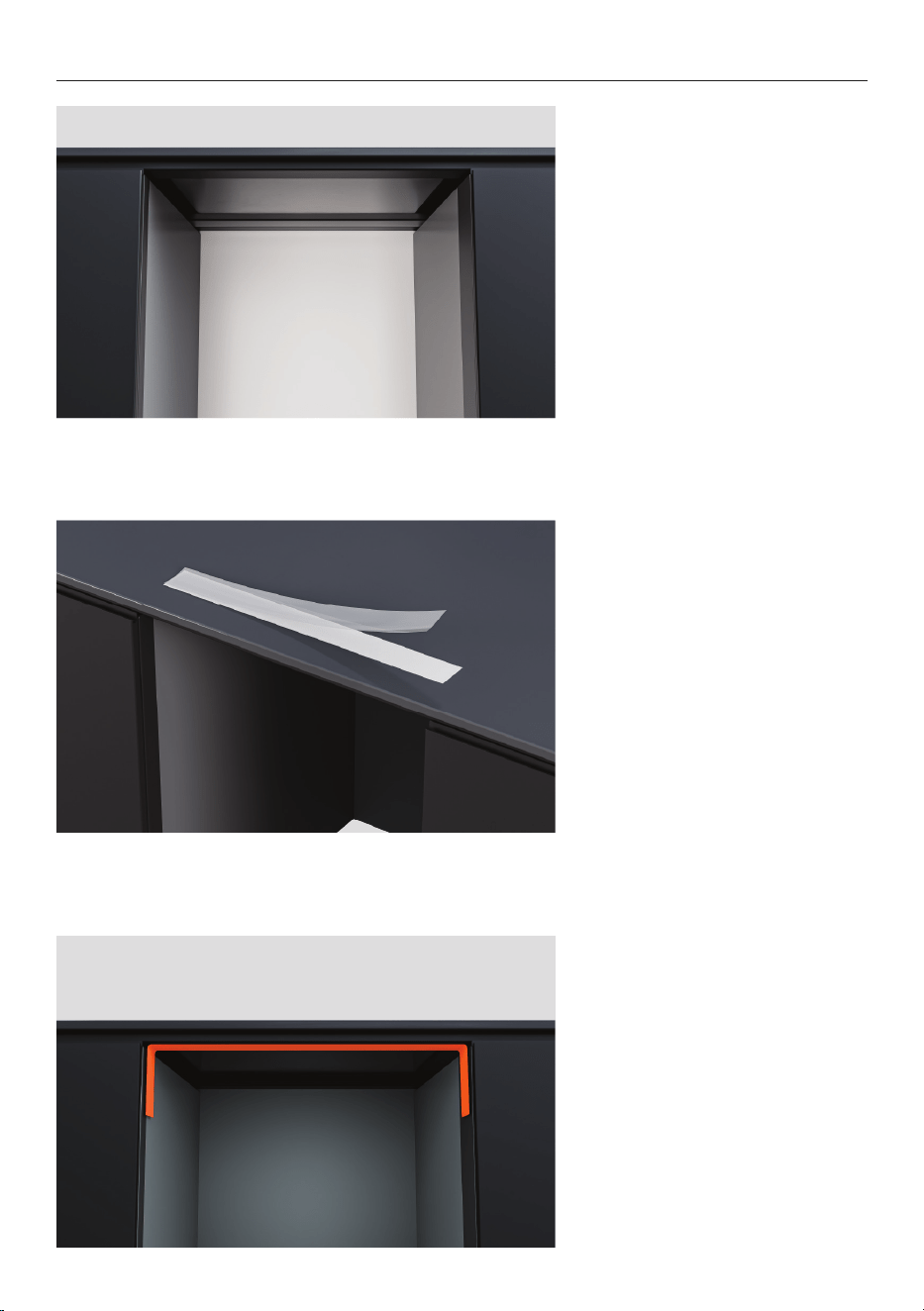
APPLY SEALING TAPE
1. Ensure underside of
countertop is clean and free of
dust.
2. Remove backing from tape
3. Apply tape to top edge of
cabinet ensuring it is centred
and set back 10mm from the
front edge.
13
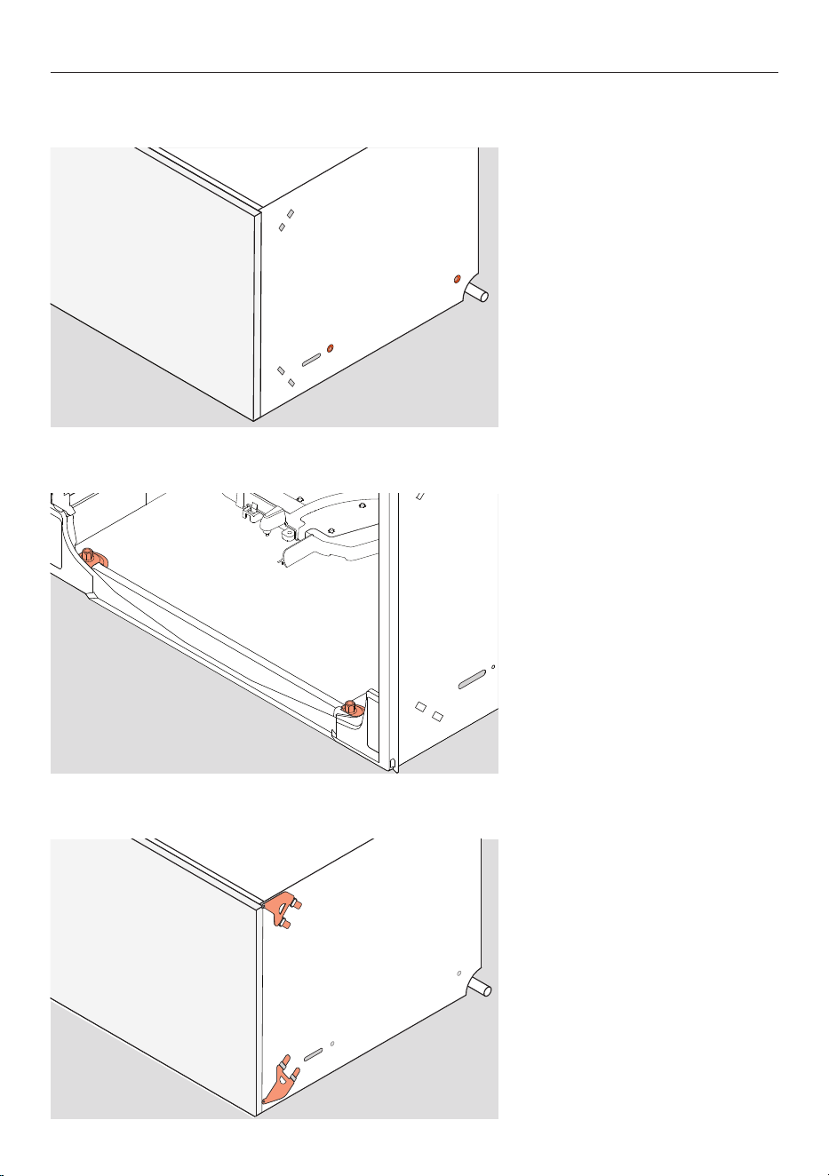
DISHWASHER SECURING OPTIONS
1. Securing through chassis
sides:
Screws must be fixed through
the chassis sides and into the
cabinet sides or packers.
The dishwasher must be secured to stay in place and prevent vibration. Three fixing points
on each side of the chassis is recommended.
2. Securing through chassis
bottom:
Screws can be fixed through
the bottom of the chassis and
into the shelf from the inside of
the dishwasher.
2x 38mm fixing screws and
washers are supplied.
3. Securing through side
brackets:
Middle or upper bracket sets
can be inserted into the chassis
sides and fixed to the edges of
the cabinet.
Both sets can be used if
needed.
14
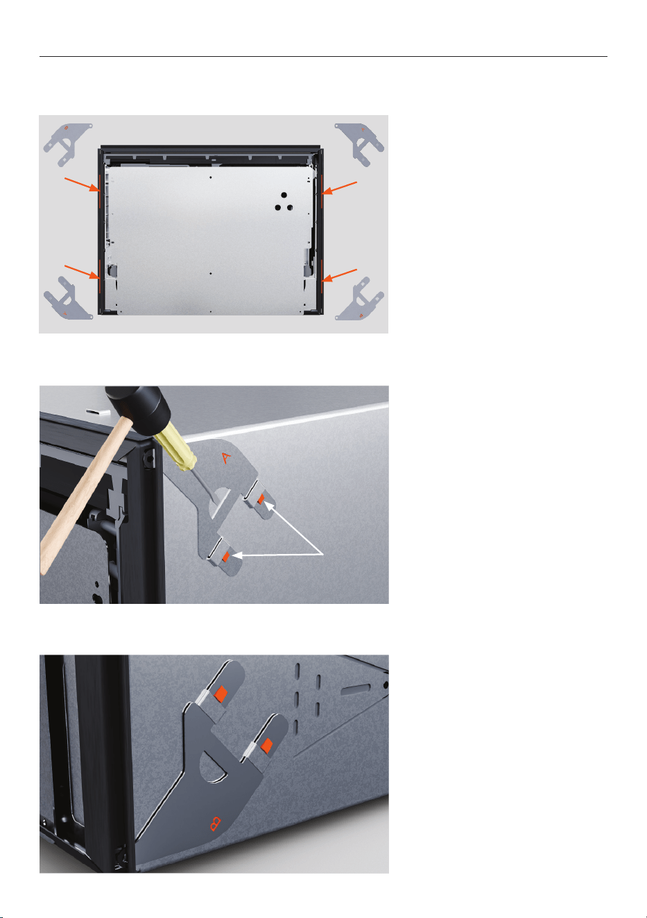
ATTACH BRACKETS
The brackets must lie flat on the chassis with the locking tabs facing out. The locking tabs
must be properly inserted through the slots to secure the brackets.
Locking
tabs
A
B
B
A
1. Locate the upper and lower
bracket sets.
2. If using the upper bracket
set, insert into the slots and
tap gently with a soft mallet to
secure.
Push the screw tab through the
gap in the rubber seal.
3. If using the lower bracket
set, insert into lower slots and
tap gently with a soft mallet to
secure.
Push the screw tab through the
gap in the rubber seal.
15
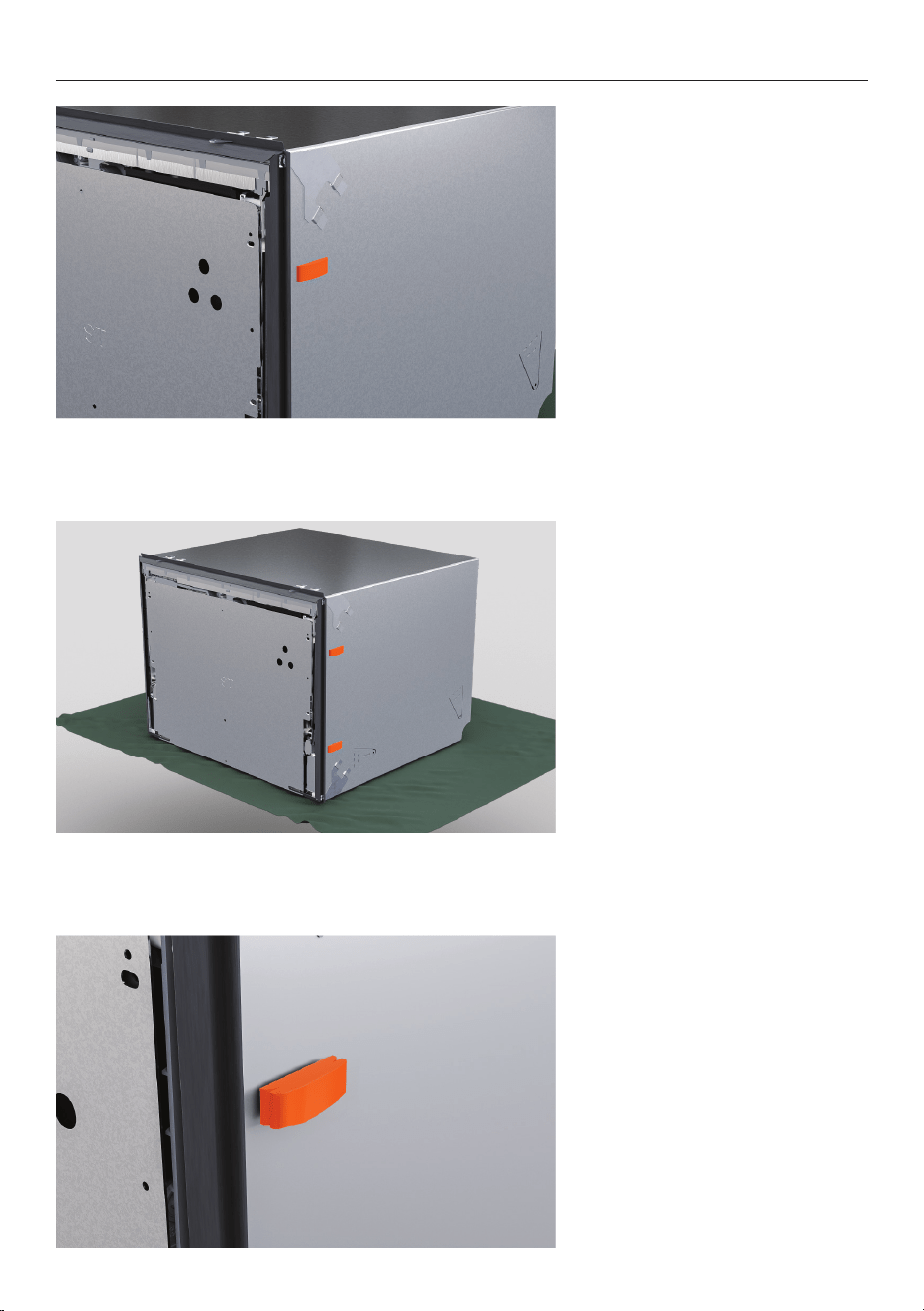
ATTACH SPACERS
1. Snap off the four spacers
with an adhesive strip.
2. Place spacers on each side
of the dishwasher between the
brackets.
3. If required a larger spacer
segment can be snapped on to
adjust the thickness.

16
ATTACH TOP TRIM
1. Align the trim to the chassis
ensuring the arrow is pointing
forward.
2. Firmly push the trim into
the slots to secure it over the
rubber seal.
3. Ensure the front of the
rubber seal is free of the
bracket.
Installing the trim bracket is recommended when fitting your dishwasher into a 480mm
high cavity to conceal any visible gap between the countertop and the chassis.
17
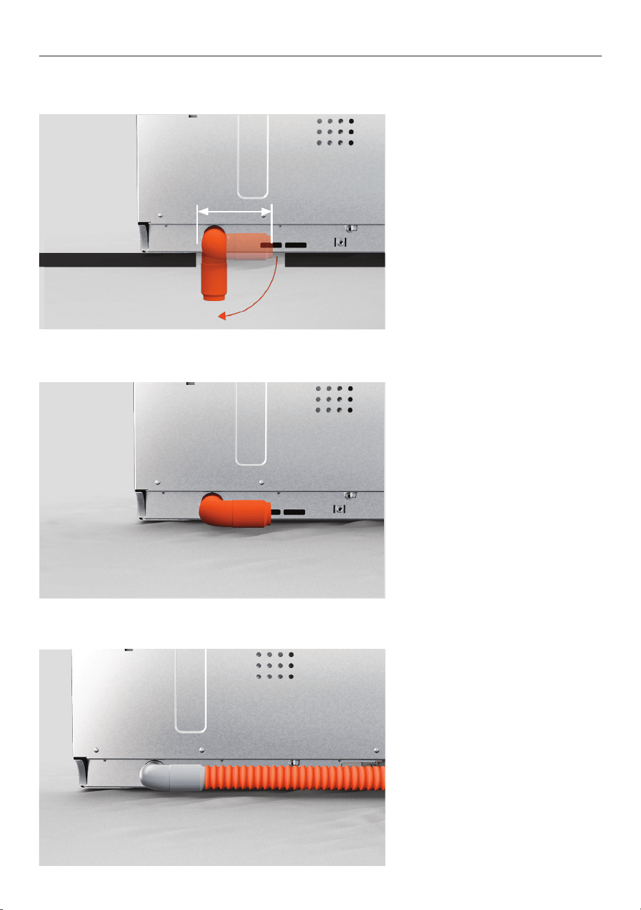
ATTACH VENT HOSE
1. Rotate the elbow to the left
or right depending on your
venting location.
The vent can be routed under
the dishwasher.
Ensure the cut out size allows
the vent elbow to be rotated
when the dishwasher is in the
cavity.
2. If the vent is routed left or
right, push the vent hose onto
the elbow firmly to secure.
Refer to the planning guide at fisherpaykel.com for venting options.
85mm
18
3. Place the panel onto the
door bracket and adjust the
dishwasher within the cavity
until the front of the panel
aligns with the cabinet doors.
PUSH INSIDE CAVITY
1. Place hoses and cords
through the service holes and
into the adjacent cavity.
2. Carefully push the
dishwasher into the cavity,
feeding the hoses through the
service holes as you go.
Avoid crushing or twisting the
hoses.
The minimum gap between the drawer panel and countertop or frame is 2mm.
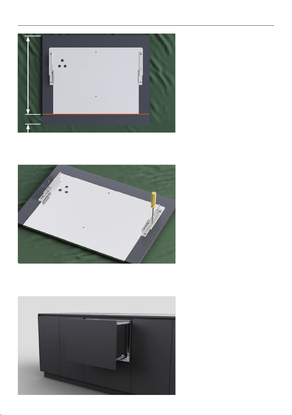
19
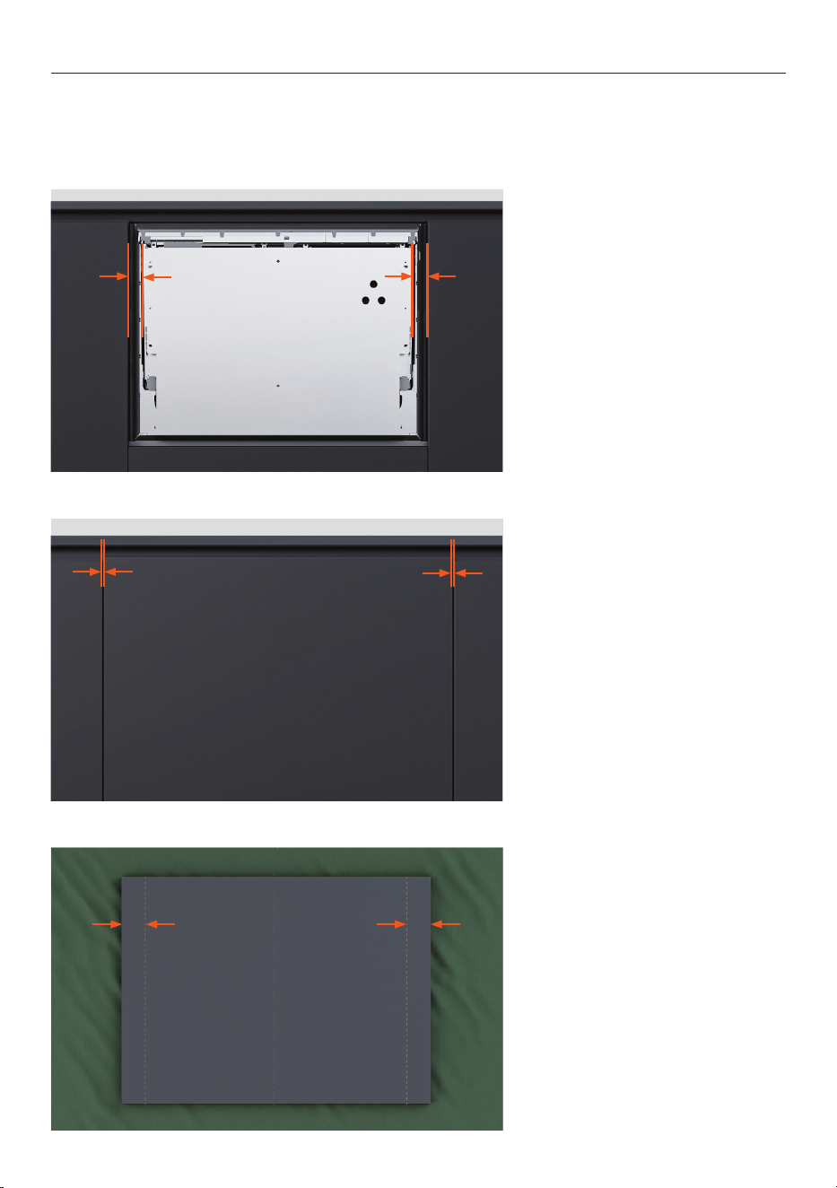
MEASURE CUSTOM PANEL
B
1. Measure the distance from
the adjacent cupboard doors to
the edges of the door bracket.
If panels widths or heights are extended over the minimum dimensions, ensure there is a
small gap between the custom panel and any cabinetry behind it.
The drawer must seal fully to prevent moisture escape and condensation, which may
damage the custom panel.
2. Subtract the required gap
between the cabinet panels
from each measurement.
The minimum required gap
to adjacent cabinet doors or
drawers is 2mm.
3. Use the final measurements
to mark vertical lines on the
back of the custom panel.
20
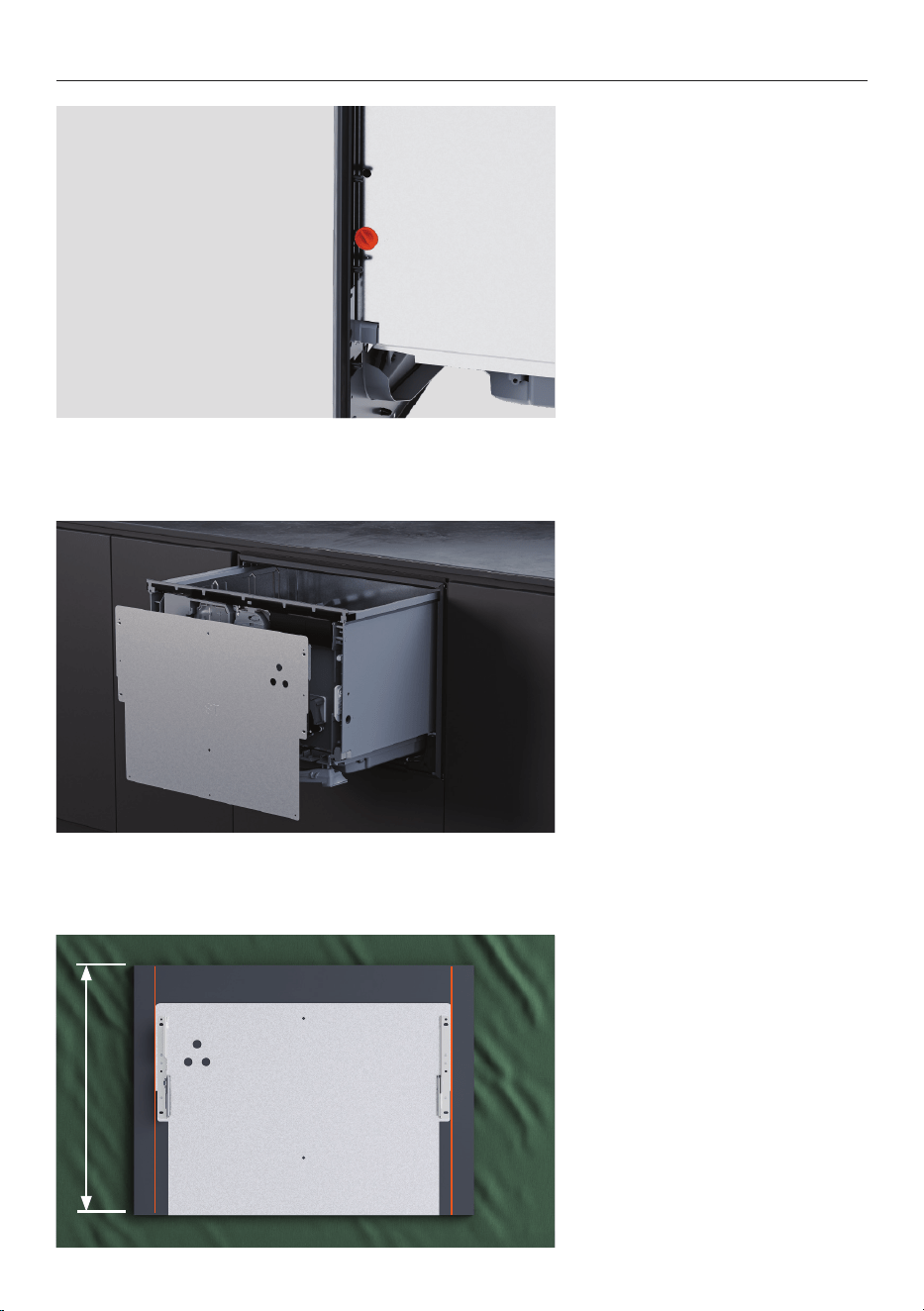
ATTACH PANEL TO DOOR BRACKET
1. Rotate the drawer bracket
pins by a quarter turn.
Use pliers to pull the door pin
out.
2. Detach the door bracket by
pulling down firmly and then
angling out.
Disconnect the earth wire from
the bracket before removing.
3. Position the door bracket on
the custom panel between the
marked lines.
Align the bottom of the bracket
with the lower edge of the
panel.
452mm
21
ATTACH PANEL TO DOOR BRACKET
6. Slot panel onto dishwasher.
Check gaps between the panel
and adjacent cabinet doors are
a minimum of 2mm.
452mmA
4. For panels extended at the
bottom:
The bracket must be raised
above the lower edge of the
panel using the extension
height (A).
5. Fix one screw in each side
through the bracket fixing
points.
Pilot holes may be required
depending on the panel
material.

22
ATTACH PANEL TO DOOR BRACKET
7. Remove the door panel and
fix the remaining four screws.
23
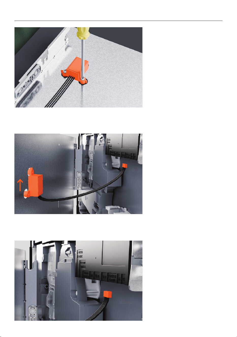
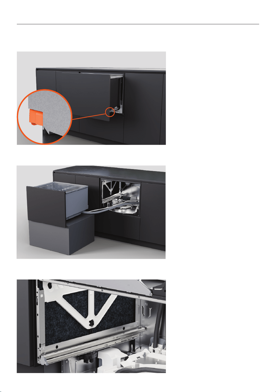
INSTALL KNOCK-TO-PAUSE MODULE
1. Secure knock-to-pause
module to the panel using the
supplied screws.
2. Check that the module is
oriented correctly and fixed
securely to ensure proper
function.
3. Move the panel to the
dishwasher.
Plug the knock-to-pause
module into the controller.
24
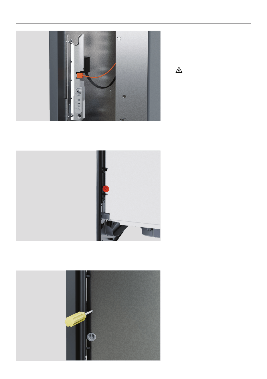
SECURE PANEL
1. Attach the earth wire to
the door bracket to ensure safe
use.
2. Place the panel back onto
the dishwasher. Insert the side
pins.
Quarter turn the pins to secure.
3. For fine vertical adjustments:
Insert a crosshead screwdriver
into the hole above side pins
and turn.
The adjustment range is ±
2mm.
25
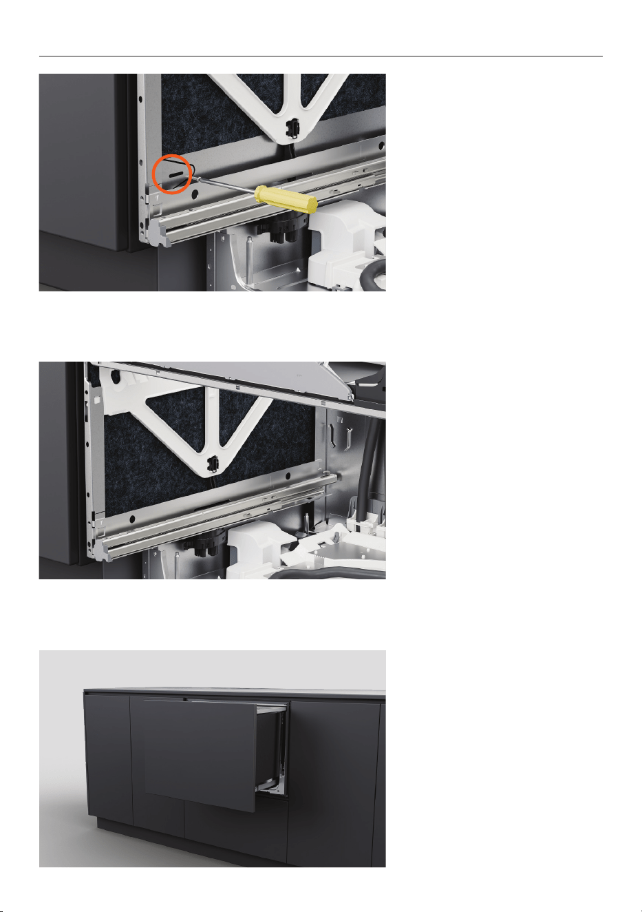
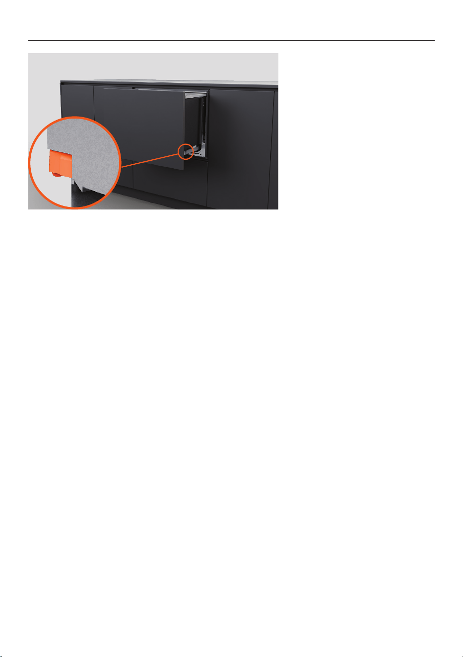
SECURE THROUGH CHASSIS SLOT
1. Pull the drawer halfway out
to remove the tub.
On each side of the tub, push
locking tabs back.
2. Place the drawer on a
protected surface to the left of
the appliance.
Slots in the chassis sides allow screws to be temporarily fixed and the dishwasher to be
adjusted within the cavity. Panel alignment can then be checked before final fixing.
3. On the chassis sides, lift the
insulation.
26
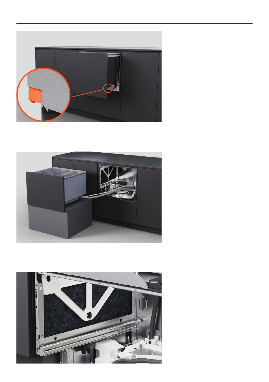
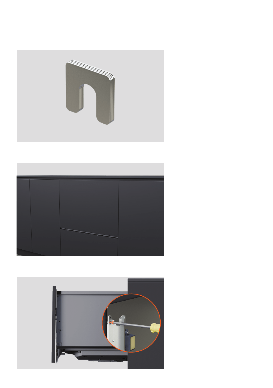
2. Refit insulation ensuring it
is positioned correctly and
will not obstruct the drawer
runners.
3. To replace the tub, pull the
drawer runners halfway out.
Place the tub onto the runners.
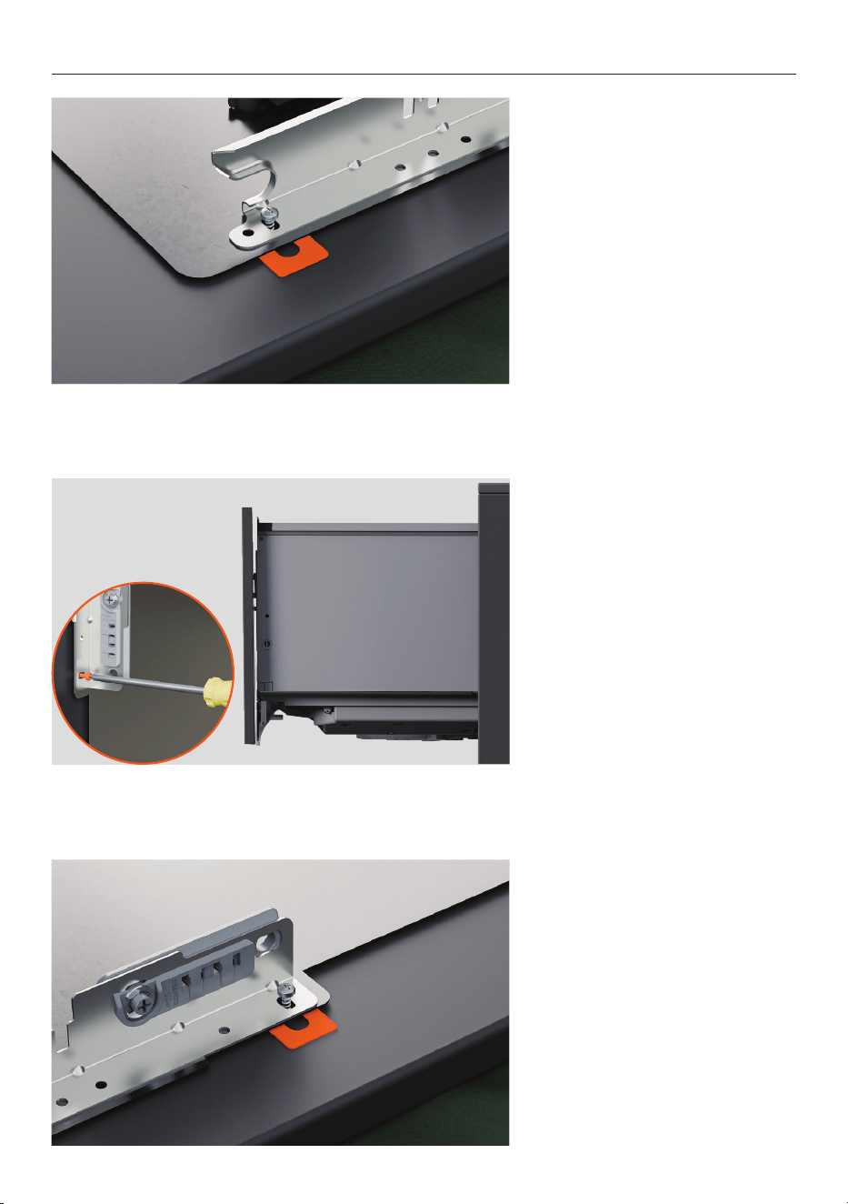
1. Fit a screw in each chassis
slot to secure to the cabinet.
Partially tighten screws
ensuring adjustments can be
made.
SECURE THROUGH CHASSIS SLOT
27
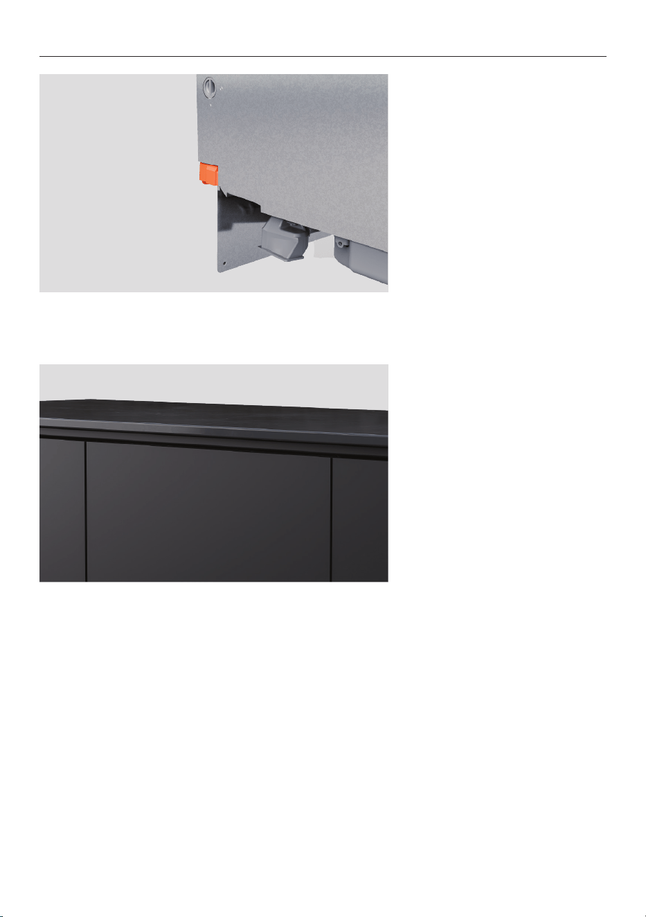
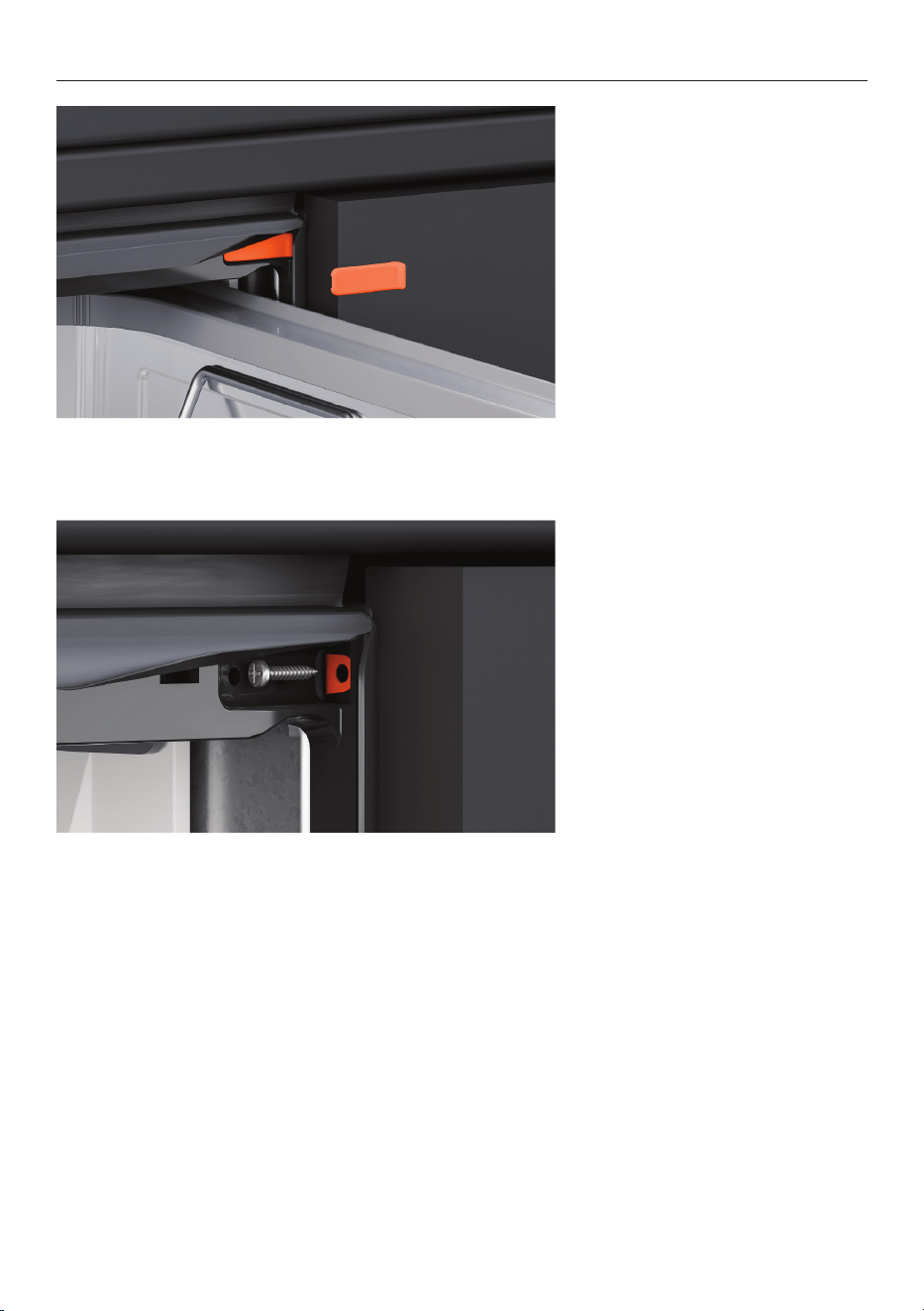
SECURE THROUGH CHASSIS SLOT
4. Pull locking tabs forward and
click the drawer into place.
Ensure hoses are not crushed
or twisted when closing the
drawer.
5. Check that the panel is
aligned with the surrounding
cabinetry.
Adjust the dishwasher in the
cavity if required.
28
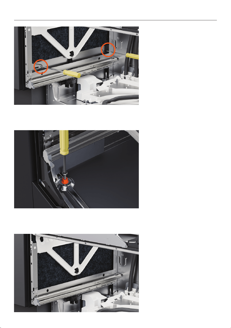
SECURE THROUGH CHASSIS
1. Pull the drawer halfway out
to remove the tub.
On each side of the tub, push
locking tabs back.
2. Place the drawer on a
protected surface to the left of
the appliance.
3. On the chassis sides, lift the
insulation.
29
4. Insert screws through the
two holes on each side of the
chassis.
SECURE THROUGH CHASSIS
5. Insert the supplied 38mm
screws and washers through
the front two holes on the
bottom of the chassis.
6. Ensure insulation is
repositioned correctly and
will not obstruct the drawer
runners.
30
7. Place the tub back onto
the runners, pull locking tabs
forward and click drawer into
place.
SECURE THROUGH CHASSIS
31
SECURE USING BRACKETS
1. If using brackets, partially
open the top drawer.
Lift the rubber seal and remove
the left and right screw covers
from the trim.
2. Fix side brackets using the
supplied screws and replace
the screw covers.
32
Shim options:
2 x 0.5mm, 4 x 0.75mm.
Do not use shims for any
adjustments over 1.75mm.
CHECK PANEL TILT
If the custom panel is slightly angled out compared to the adjacent cabinetry, the supplied
shims can be used to make minor adjustments.
1. Remove the panel and door
bracket if adjustment is needed.
2. For panels tilted outward at
the bottom of the dishwasher:
Loosen the screws at the top of
the bracket on each side.
33
3. Insert the shim between the
panel and the door bracket and
tighten the screw.
Slot the panel onto the
dishwasher and check.
CHECK PANEL TILT
4. For panels tilted outward at
the top of the dishwasher:
Loosen the screws at the
bottom of the bracket on each
side.
5. Insert the shim between the
panel and the door bracket and
tighten the screw.
Slot the panel onto the
dishwasher and check the
drawer panel alignment.
34
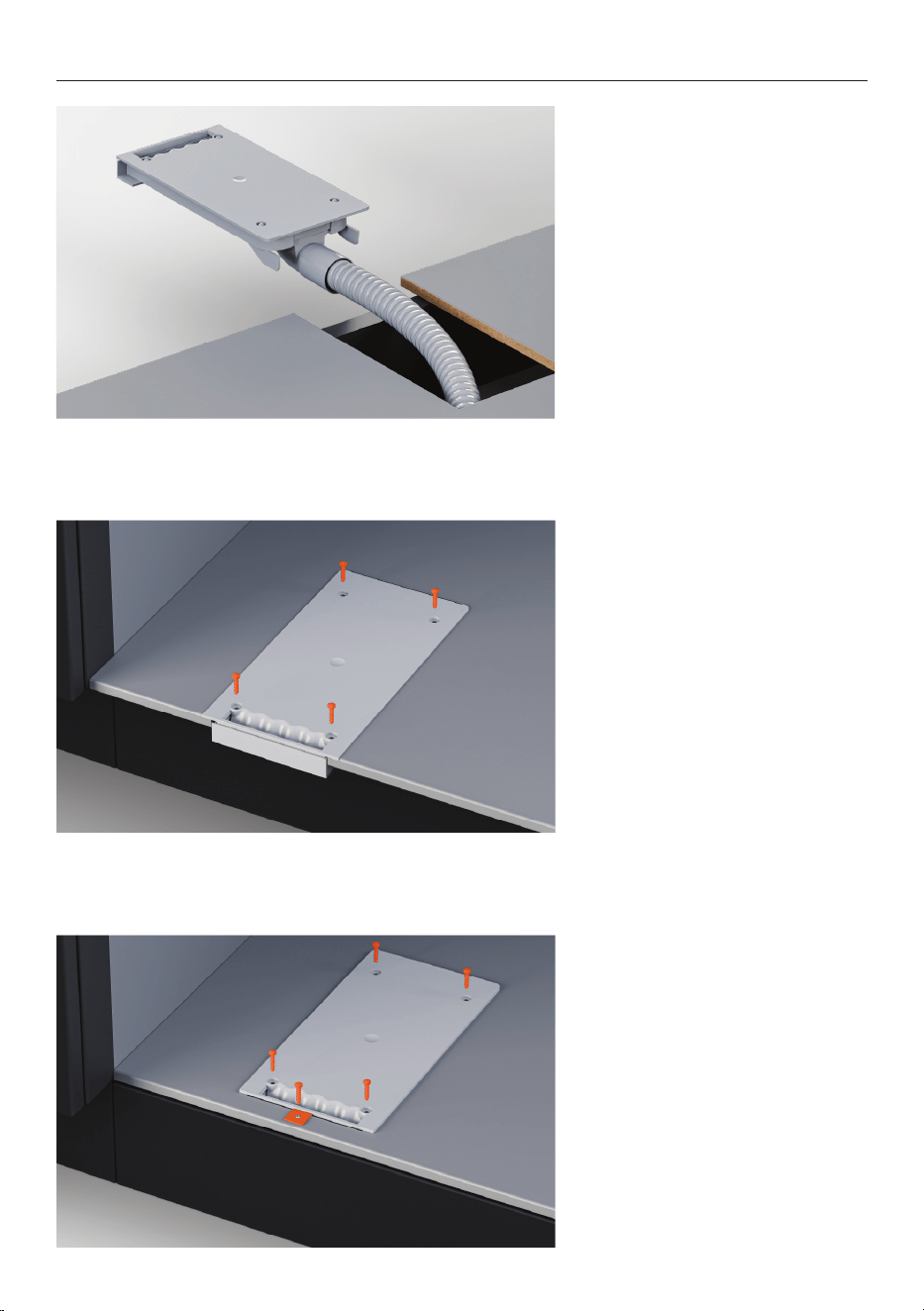
1. Feed the venting hose into
the toe kick space in the
adjacent cabinet or under the
dishwasher as required.
INSTALL VENT
2. The vent hose can be coiled
in the toe kick space.
Ensure that there are no sharp
bends or kinks.
The vent hose should not exceed a maximum length of 1.6 meters. Do not shorten the
hose.
If the cabinet is framed or
cannot be installed on the shelf
edge, cut off the edging on the
vent duct.
35
INSTALL VENT
4. Secure the vent using the
provided screws.
5. For framed cabinetry, install
the bracket and screw included
in the venting kit.
3. Pull the end of the venting
hose through the cut-out and
firmly attach it to the vent duct.
36
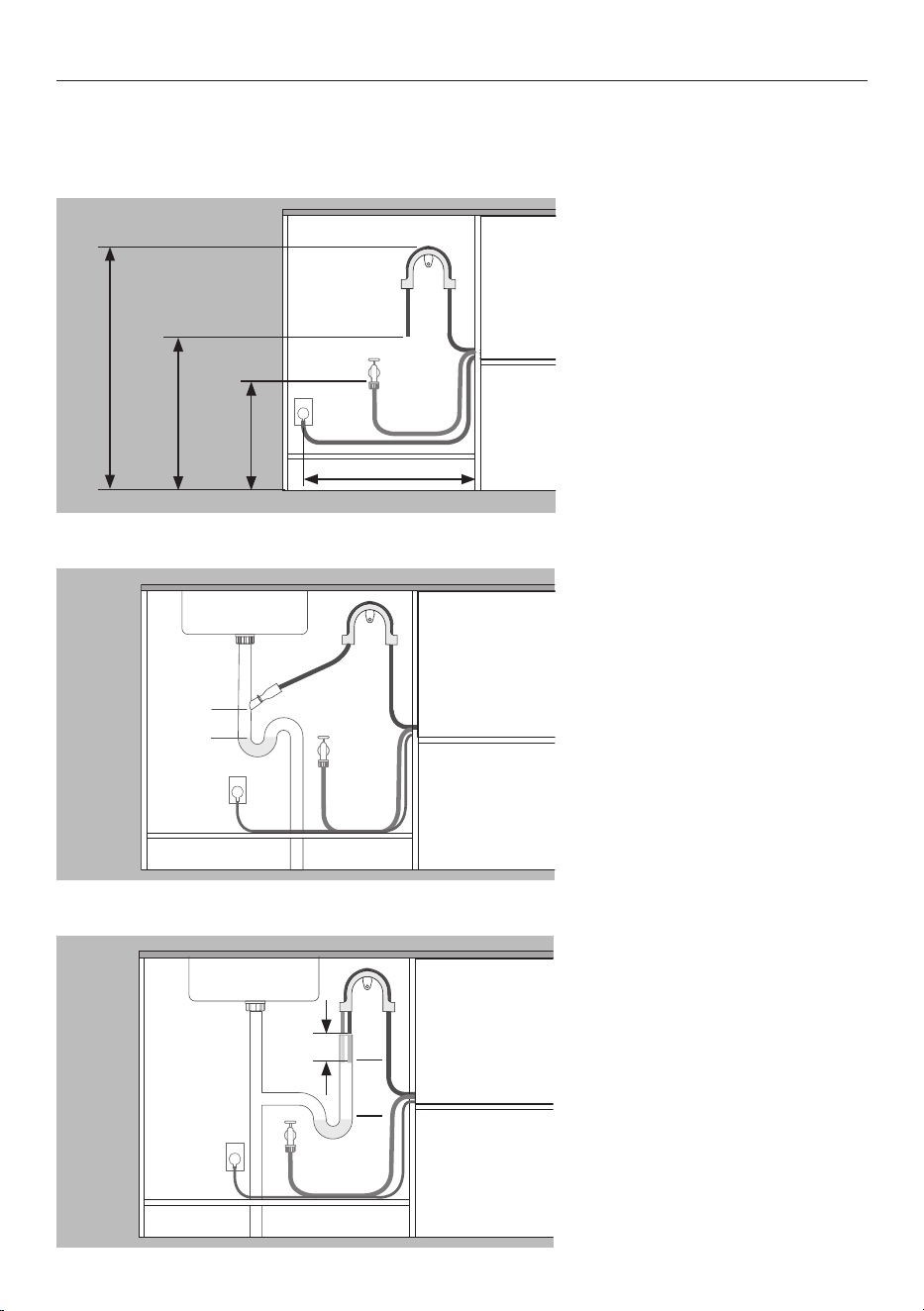
DRAIN CONNECTION OPTIONS
DD60STX6HI1 Water pressure: maximum 1 MPa (145 psi), min. 0.1 MPa (14.5 psi).
DD60STX6I1 Water pressure: maximum 1 MPa (145 psi), min. 0.03 MPa (4.3 psi)
Water connection: 3/4” BSP (GB20) to suit flat washer, recommended temperature: cold 60C
Distances are the same for all
installs.
z
Floor to support
top - min 750mm.
z
Floor to drain hose
end - min 500mm.
z
Floor to water
inlet - min 200mm.
z
Cabinet side to centre of
electrical outlet - 450mm.
Drainage routed to spigot
z
Spigot must be higher than
standing water with an
air gap between to avoid
drainage issues.
z
Remove excess drain hose
to prevent hose drooping
below the spigot height.
Drainage routed to standpipe
z
Drain hose must be higher
than standing water with an
air gap between to avoid
drainage issues.
z
Remove excess drain hose.
z
Hoses must not extend into
standpipe more than 120mm.
Max 450mm
Min
750
mm
Min
500
mm
Min
200
mm
Air gap
120
mm
Air
gap
37
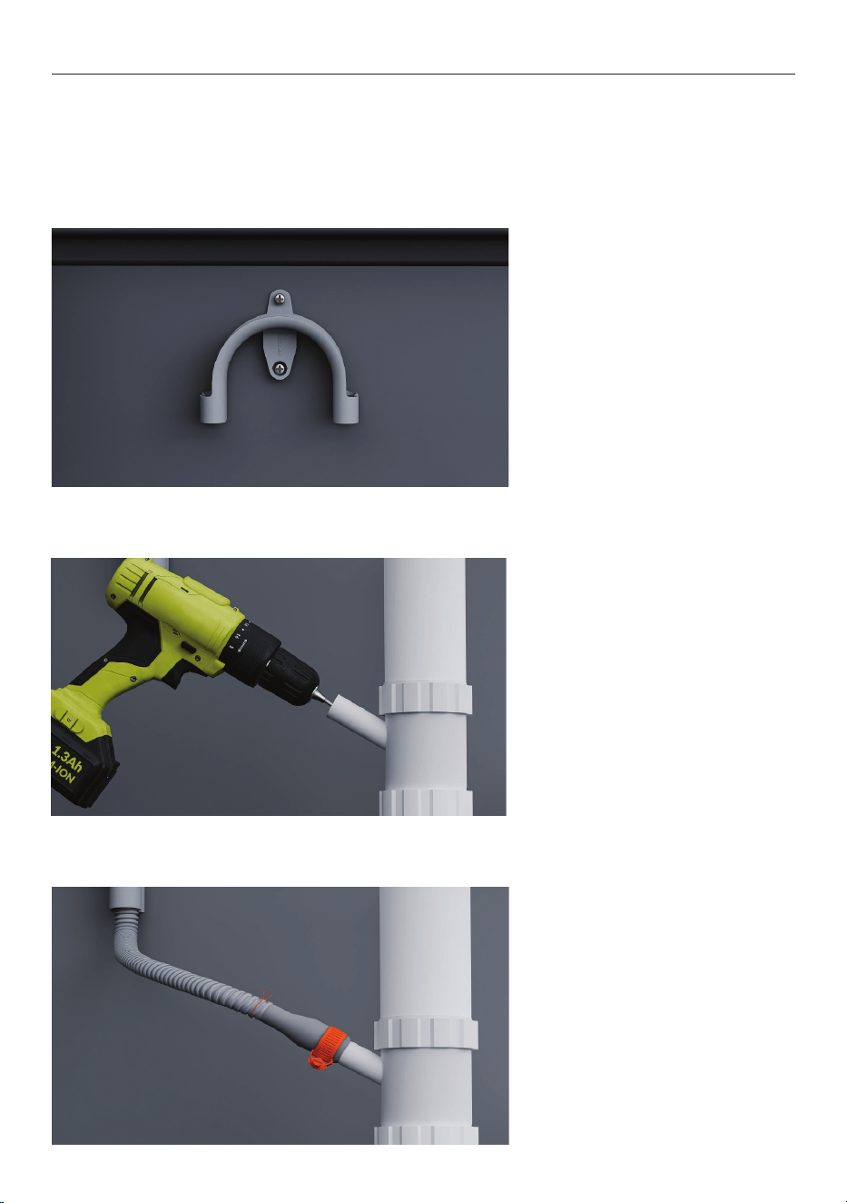
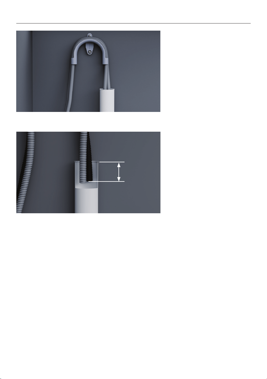
INSTALL DRAIN
1. Install the drain hose support
as close to the countertop
as possible, with a minimum
distance of 750mm from the
floor
Thread the hose though the
support.
Ensure the drain hose support is properly installed and the hose is correctly threaded
through to prevent damage and drainage issues.
The dishwasher must not be drained into standing water.
If the drain hose supplied is not long enough to reach your services, a 3.6m drain hose
extension kit is available at fisherpaykel.com
2. For connection to waste tee:
To avoid shavings entering the
plumbing system, remove the
waste tee before drilling.
Unplug or drill out the waste
tee minimum 13mm in diameter
before securing joiner.
3. Thread wire clips on to the
hoses.
Fit the hose to the supplied
hose joiner and secure using
the wire clips provided.
Ensure hose is routed straight
to the joiner to avoid kinks that
restrict drainage.
Trim drain hose if needed.
38
INSTALL DRAIN
4. For connection to standpipe:
Pull both drain hoses through
the support guide and rest in
standpipe.
5. Ensure the hoses do not
extend more than 120mm
into the standpipe to prevent
wastewater siphoning back into
the tub.
Hoses can be trimmed if
necessary.
120mm
39
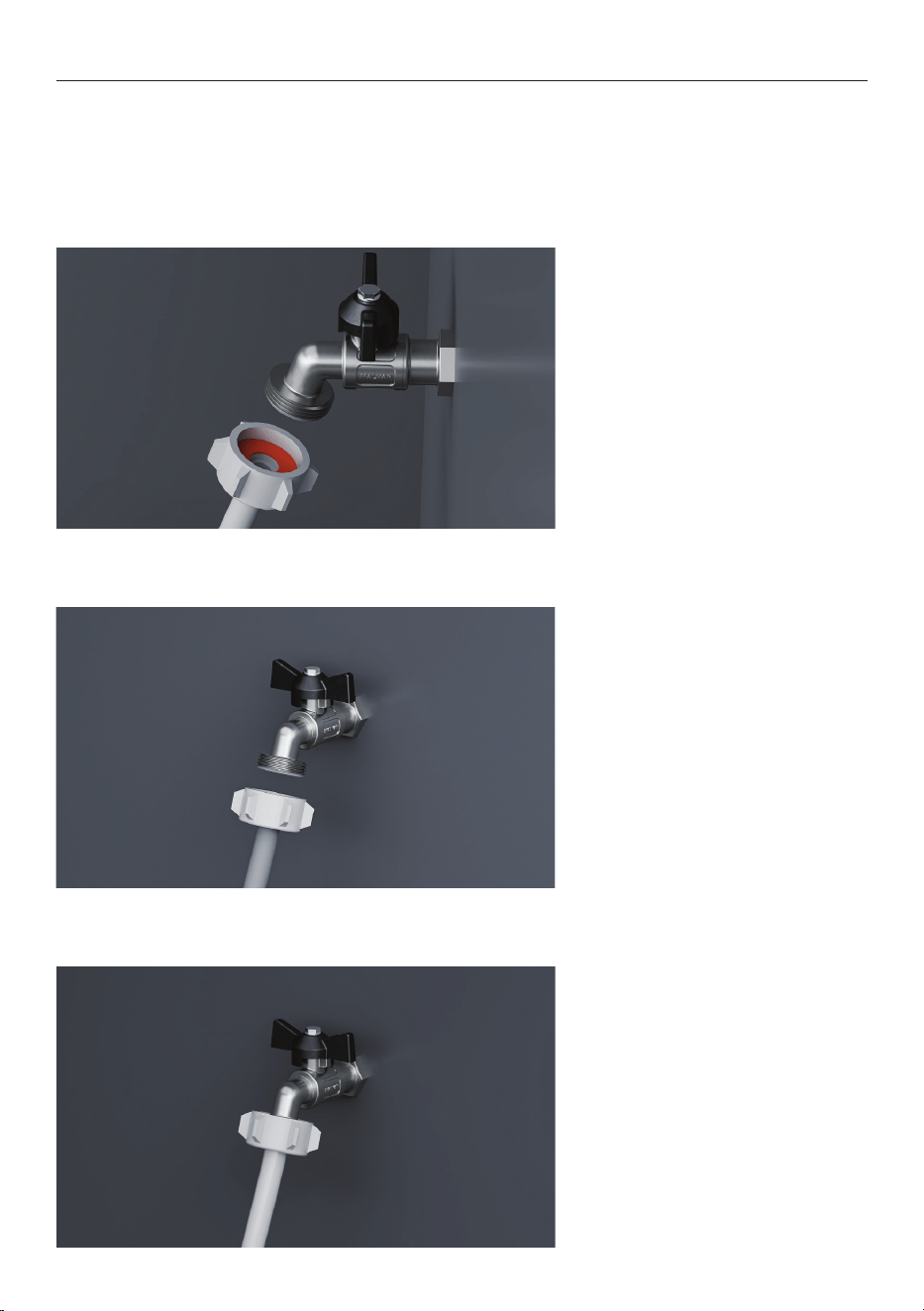
CONNECT WATER INLET
1. Check that the supplied
rubber washer is inserted into
the coupling.
Do not turn water supply on before power has been connected. The dishwasher must be
powered on for flood protection to be enabled.
Isolation taps are required to allow the water supply to be shut off.
2. Connect the inlet hose to the
tap.
Ensure the inlet hose is not
kinked and the tap is not pulled
or under pressure.
Do not shorten the inlet hose.
3. Hand-tighten into place.
Using a spanner or pliers, turn
a further 180° to secure. Avoid
over-tightening.
40
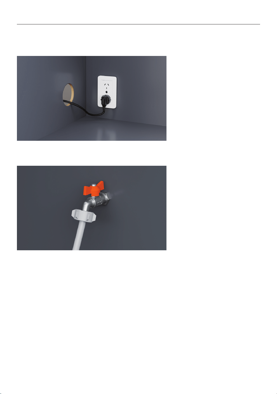
CONNECT POWER
1. Connect power.
2. Check the water connections.
Turn on the water supply and
check for leaks.
The dishwasher must be
powered on for flood
protection to be enabled.
If power is to be disconnected,
ensure water supply is turned
off.
Electrical requirements: 220 - 240V minimum 4.8A
The power plug should be accessible after installation for maintenance.

41
INSTALLER CHECKLIST
Installation
F If power is disconnected, ensure water supply is turned off to prevent flooding.
F Check all parts are installed correctly and are secure.
F Ensure all clearance gaps have been maintained.
F Ensure dishwasher is secure and drawer opens and closes freely with no resistance.
F Ensure panel is fitted correctly to the dishwasher
F Ensure any packaging or tape securing the racks and spray arm is removed.
F Check the spray arm is in place, mounted correctly and rotate freely.
F Ensure knock-to-pause module is fitted securely and operating correctly.
Plumbing
F Ensure any knock-outs or plugs in drain connection have been drilled out and drain
connection has been made.
F The drain hose joiner must not support the weight of excess hose material. Keep drain
hose as fully extended as possible to prevent sagging. Any excess length of drain hose
should be kept on the dishwasher side of the high loop.
F Ensure inlet hose has supplied rubber washer fitted, and that it’s tightened.
F If connecting the drain hose to the sink trap, ensure the high loop is a minimum
150mm higher than the drain hose joiner.
F Water softener models: adjust the water softener setting from the default setting to
suit the water hardness of the area. Refer to your user guide.
F Ensure water supply is turned off until power is connected and turned on. The
Dishwasher must be powered on for the flood protection feature to be enabled.
Electrical
F Ensure all electrical tests have been conducted in accordance with local regulations.
Test operation
F Turn on the power and water supplies, then open the drawer. You should hear a beep
and see a program indicator light up on the control panel.
F Add three cups of water into the drawer.
F Navigate to RINSE and start the program.
F Check the knock-to-pause function
F Repeat for the other drawer.
F After the Rinse cycle has finished, ensure the dishwasher has run and drained
correctly.
F Check the water supply has been shut off correctly.
F Check drainage connections for leaks.
F If site is left without power after installation is complete, ensure water supply is
turned off to prevent flooding.

42
Complete and keep for safe reference:
Model
Serial no.
Purchase date
Purchaser
Dealer address
Installer’s name
Installer’s signature
Installation company
Installation date
INSTALLER CHECKLIST


592364C 07.25
FISHERPAYKEL.COM
© Fisher & Paykel Appliances 2025. All rights reserved.
The models shown in this guide may not be available in all markets
and are subject to change at any time.
The product specifications in this guide apply to the specific products and
models described at the date of issue. Under our policy of continuous product
improvement, these specifications may change at any time.
For current details about model and specification availability in your country,
please go to our website or contact your local Fisher&Paykel dealer.