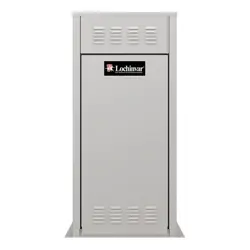
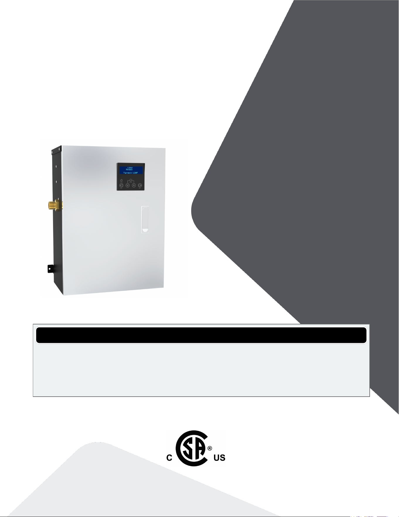
Electric Boiler
4K, 8K, 10K and 12K models
INSTALLATION &
OPERATINGMANUAL
WARNING
Risk of electric shock. If the information in this manual is not followed exactly, a fire or
electrocution may result causing property damage, personal injury, or loss of life.
Do not store or use gasoline or other flammable vapors and liquids or other combustible
materials in the vicinity of this or any other appliance.

Water quality
Warning
Water quality has a significant impact on the lifetime and performance of a boiler's heat
exchanger.
Improperly prepared water in a heating circuit may cause damage to the heat exchanger
through fouling or corrosion. Repeated or uncontrolled water fills will increase the potential
for damage.
High levels of dissolved solids or minerals may precipitate out of the fluid onto the hottest part
of the heat exchanger, impairing heat transfer and resulting in overheating and premature
failure. The amount of solids that may form on the heat exchanger will depend on the degree
of hardness and the total water volume in the system. A high water volume system with a low
hardness count may cause as much damage as a system with less volume and higher
hardness, so it is recommended to treat water so as to reduce dissolved solids to the
minimum 10 ppm, and to no more than 30 ppm. Water chemistry allowable limits are as
follows:
TDS 0.6 to 1.75 grains/ gal (10 to 30 ppm)
Acidity pH is to be between 6.6 and 8.5
Chloride is to be less than 125 mg/l
Iron is to be less than 0.3 mg/l
Cu less than 0.1 mg/l
Conductivity is to be less than 400μS/cm at 77°F (25°C)
Important: Ensure that these limits are acceptable for the other water-side components in
the system.
Shipped with the boiler:
1 x Wall mounting bracket
1 x 30 psig pressure relief valve
3
2.0 Safety information
Manual safety markings
Danger
Points out an immediate hazardous
situation that must be avoided to
prevent serious injury or death.
Warning
Points out a potential hazardous
situation that must be avoided to
prevent serious injury or death.
Caution
Points out a potential hazardous
situation that must be avoided to
prevent possible moderate injury
and/or property damage.
Note
Points out installation, maintenance and
operational notes to enhance efficiency,
longevity and proper operation of the
boiler.
Important safety instructions
Installation, start-up and servicing of these boilers must be performed by competent, qualified,
licensed and trained heating technicians.
Failure to read and comply with all instructions and applicable national and local codes may result in
hazardous conditions that could result in property damage and injury to occupants, and in extreme
cases to death. Keep instructions near the air handling appliance for future reference.
Danger
Do not store or use gasoline or other flammable vapors or liquids in the vicinity of this or
any other appliance. If you smell gas vapors, do not try to operate any appliance - do not
touch any electrical switch or use any phone in the building.
Warning
Do not use this boiler if any part has been under water. Immediately call a qualified service
technician to inspect the boiler and to replace any part of the system that has been under
water.
Warning
Improper installation, adjustment, alteration, service or maintenance can cause property
damage, personal injury, or loss of life. Read and understand the entire manual before
attempting installation, start-up, operation, or service. Installation and service must be
performed only by an experienced, skilled installer or service agency.
Failure to follow all instructions in the proper order can cause personal injury or death.
Read all instructions, including all those contained in component manufacturers’ manuals
before installing, starting up, operating, maintaining, or servicing the appliance.
Warning
Disconnect power supply before any wiring/service is performed. Failure to do so could
result in damage to appliance and/or electric shock.
Caution
The boiler must be installed so that electrical components are not exposed to water
during operation.
Known contaminants
Known Corrosive Contaminants to Avoid
Cements and glues Refrigerant leaks from cracks in coils
Paint or varnish removers Sodium chloride or potassium chloride used for
water softening
Adhesives used to fasten building products
and other similar products
Chemicals in perming solutions
Chlorinated waxes or cleaners Chlorofluorocarbon chemicals found in spray cans
Chlorine-based swimming pool chemicals Antistatic dryer sheets in clothes dryers
Hydrochloric acid or muriatic acid used in
household cleaning and stain removal
Chlorine-type bleaches, detergents, and cleaning
solvents found in household laundry rooms
Calcium chloride used for snow clearing
SAVE THESE INSTRUCTIONS
4
Section: Safety information

5
3 Specifications
Boiler Specification 4 kW 8 kW 10 kW 12 kW
Power @ 240V 1.3 - 13.7 MBH
0.4 - 4.0 kW
2.7 - 27.3 MBH
0.8 - 8 kW
3.4- 34.1 MBH
1.0 - 10.0 kW
4.1 - 41.0 MBH
1.2 - 12.0 kW
Power @ 208V 1.0 - 10.2 MBH
0.3 - 3 kW
2.1 - 20.5 MBH
0.6 - 6.0 kW
2.6 - 25.6 MBH
0.8 - 7.5 kW
3.1 - 30.7 MBH
0.9 - 9.0 kW
Maximum Current Draw (with
pump) @ 240V
17.6 A 34.2 A 42.6 A 50.9 A
Maximum Current Draw (with
pump) @208V
15.4 A 30.0 A 37.1 A 44.3 A
Breaker Size 30 A 45 A 60 A 70 A
Minimum Ambient temperature 32°F / 0°C
Max. Ambient temperature 122°F / 50°C
Maximum relative humidity
(non-condensing)
90%
Minimum water temp. 34°F / 1°C
Maximum water temp.
(electronic hi-limit)
190°F/ 88°C
Max. Water Temperature
Lockout Limit
210°F/ 99°C
Weight (empty) 29 lbs / 13.2 kgs
Minimum boiler flow rate 0.7 USgpm /
2.6 Lpm
1.4 USgpm /
5.3 Lpm
1.7 USgpm /
6.4 Lpm
2.1 USgpm /
8.0 Lpm
Maximum boiler flow rate 4.2 USgpm / 16 Lpm
Maximum operating water
pressure*
50 psig / 345 kPa
Minimum water pressure
8 psig / 55 kPa
Element construction Titanium
*Boiler ships with a 30 psi Pressure Relief Valve
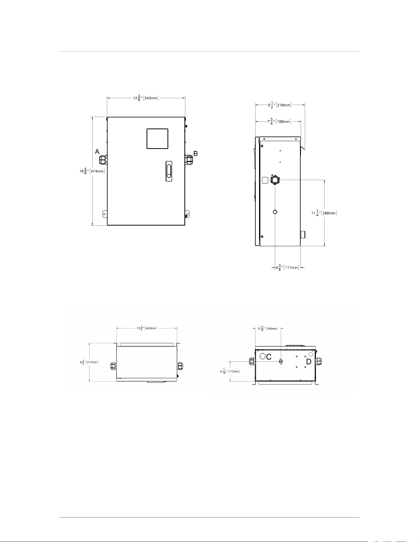
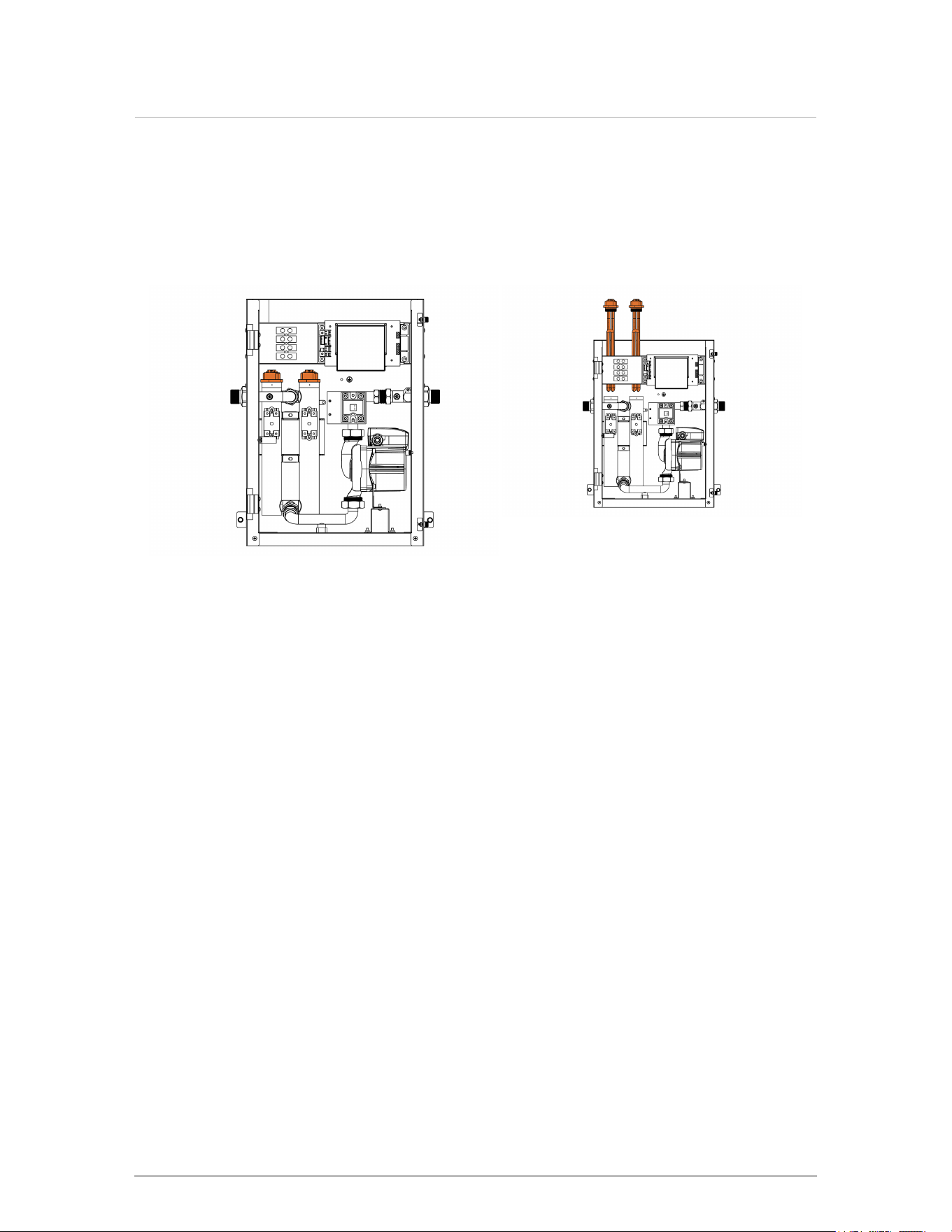
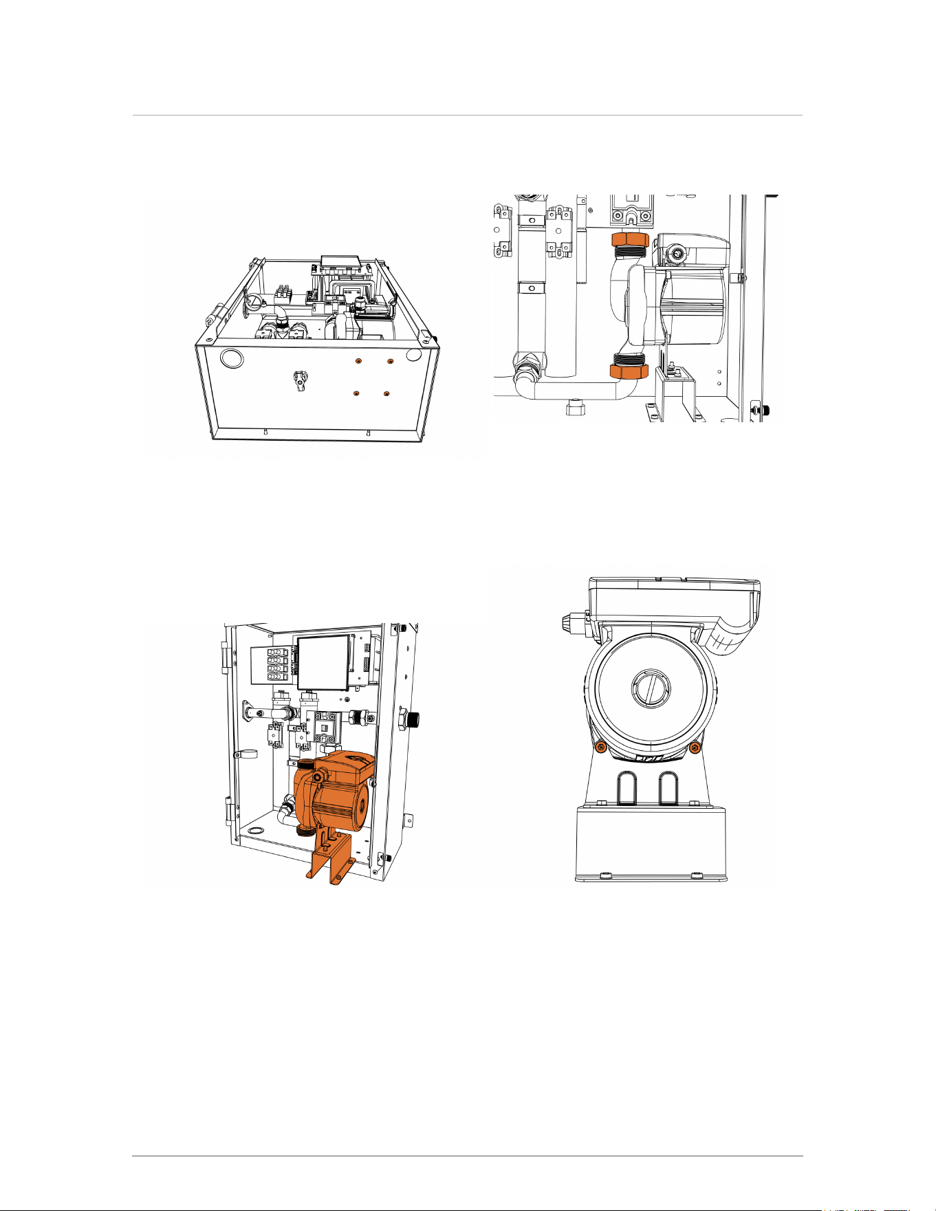
Cabinet dimensions
Figure 1 Frontal view - electric boiler all models Figure 2 Side view - electric boiler all models
Figure 3 Top view - electric boiler all models Figure 4 Bottom view - electric boiler all models
6
Section: Specifications

Connection specifications
The following table displays the required connection specifications.
Description Connection details
A Supply water outlet 3/4" NPT-M
B Return water inlet 3/4" NPT-M
C Supply power knock-out Dual 3/4" and 1"
D Control wiring knock-out 1/2"
Table 1 Connections
7
Connection specifications

Intentionally left empty

4.0 Introduction
4.1 Standard features and benefits
Compact
Modulating
Boiler pump built in
Easy set-up for Set-Point or Outdoor Reset heating
Flow-proving and high limit safeties built in
4.2 Warranty
For residential applications, the manufacturer offers a 1-year warranty on the pump and the
elements. All other parts carry a 5-year warranty against defects in materials or workmanship and
failures due to thermal shock.
For commercial applications, the manufacturer offers a 1-year warranty on all parts against defects
in materials or workmanship and failures due to thermal shock.
To view the full warranty statement for this product, go to the manufacturer's website.
9
4.0 Introduction
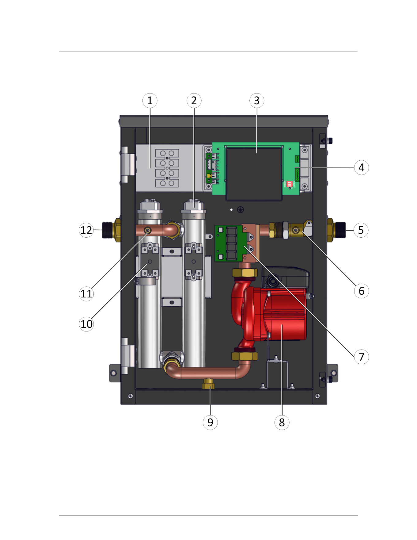
4.3 Internal view
10
Section: Introduction
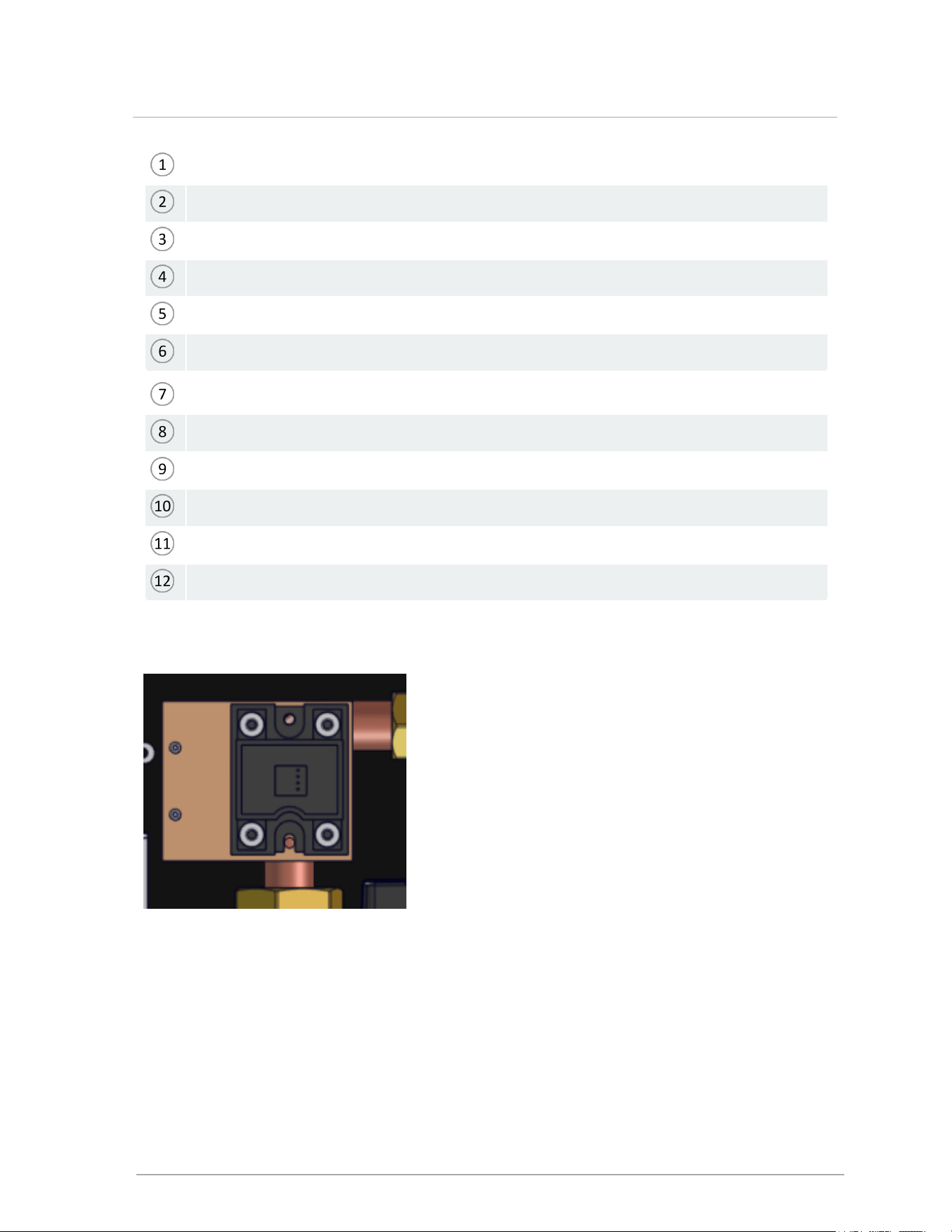
Incoming power wiring connections
Heating element (1 of 2)
Display screen / controller
Control wiring terminals
Return piping connection 3/4" NPT
Flow sensor / inlet temperature sensor assembly
Triac relay (modulation control block): see below for alternate
3-speed pump
Drain port
High temperature limit switch (manual reset)
Outlet temperature sensor
Outlet piping connection 3/4" NPT
Figure 5 Interior view
Figure 6 Item 7 Solid state relay--alternate modulation control block
11
4.3 Internal view
5.0 Before installation
Before installing the appliance, it is important to review and observe the following checklist of
precautions:
Caution
Care must be taken to properly size the boiler for its intended use. Prolonged full output run
time, over-sizing or under-sizing, and incorrect flow rates through the boiler can lead to
increased maintenance costs, equipment stress and premature failure.
Precautions Check
Exposure to corrosive chemical fumes such as chlorinated and/or fluorinated
hydrocarbons can reduce the life of a boiler. Cleaners, bleaches, air fresheners,
refrigerants, aerosol propellants, dry-cleaning fluids, de-greasers and paint-removers all
contain vapors that can form corrosive acid compounds. Airborne chlorides such as those
released with the use of laundry detergents are also to be avoided.
□
Locate the boiler where water leakage will not result in damage to the area. If there is no
suitable location, install a suitable drain pan under the boiler. Do not install above
carpeting.
□
At a new construction site, or during renovations, protect the boiler from drywall dust or
other construction related contaminants. Do not seal boiler case openings directly when
operating - allow for air circulation and ventilation in the immediate area.
□
Ensure that the pressure relief valve is installed with no valves or other means of isolation
between its inlet and the boiler. Make sure the relief valve outlet is piped with unobstructed
piping (minimum ¾" diameter) to a safe discharge location.
□
12
5.0 Before installation
6.0 Installation
If you haven't performed the necessary pre-installation checks, see Pre-installation checks.
Refer to the Specifications section for dimensional drawings and connection specifications. Use these
drawings to find a suitable location for the appliance.
6.1 Code requirements
The appliances are tested and certified under CSA22.2 No.165-17 and/or UL834 (5th edition). Below
are the code requirements for every installation.
Canada US
Conform to local codes, or in the absence of
these, with the latest editions of the Canadian
Electrical Code Part 1 CSA C22.2 No. 165-17.
Conform to the current National Electrical Code
ANSI/NFPA 70 and UL 834 (5th edition).
Table 2 Code requirements by country
6.2 Removing an existing gas boiler
When an existing gas boiler is removed from a common venting system, the common venting
system may be too large for proper venting of the appliances that remain connected to it. When
resizing any portion of the common venting system, use the minimum size according to the
appropriate tables in the National Fuel Gas Code, ANSI Z223.1 - latest edition. In Canada, follow
the B149.1 Installation Code.
When removing an existing gas boiler, the following checks must be carried out for each of the
appliances still connected to the common exhaust system, by operating them one at a time:
Seal any unused opening in the common venting system.
Visually inspect the venting system for proper size and horizontal pitch. Determine that
there is no blockage or restriction, leakage, corrosion and other deficiencies that could
cause an unsafe condition.
(Where practical) Close all building doors and windows such as doors adjacent to
appliances remaining connected to the common venting system and other spaces of the
building.
Turn on clothes dryers and any appliance not connected to the common venting
system.
13
6.0 Installation
Turn on any exhaust fans, such as range hoods and bathroom exhausts, so they
will operate at maximum speed. Do not operate a summer exhaust fan.
Close fireplace dampers.
Place in operation the appliance being inspected.
Follow the lighting instructions.
Adjust the thermostat so that the appliance operates continuously.
After determining that each appliance remaining connected to the common venting
system properly vents when tested as outlined above, return doors, windows, exhaust
fans, fireplace dampers and any other gas-burning appliance to their previous condition.
Any improper operation of the common venting system should be corrected, so the
installation conforms with the National Fuel Gas Code, ANSI Z223.1 - latest edition. In
Canada, all installations must conform with the current CAN/CGA - B149.1-10
Installation Code and/or local codes.
6.3 Determining the location of the boiler
The boilers are designed and approved for indoor installation (wall or rack mounting) in areas
such as an alcove, basement, or utility room. These areas should have a surrounding
temperature of 32°F (0°C) to 122°F (50°C) and less than 90% relative humidity.
Warnings
Keep the area around a boiler clear of combustible materials, gasoline, and
other flammable vapors and liquids.
Ensure that a boiler is not exposed to water leaks from piping or components
located overhead, including condensation from uninsulated cold water lines
overhead.
Ensure that combustible materials do not make contact with exposed water
piping and associated components (relief valves, circulators, etc.). Check local
codes for required clearances and/or provide adequate insulation.
6.4 Mounting the boiler
Warning
Do not mount the appliance to hollow wall structures - The combined weight of
the boiler, its water content and associated piping components can exceed 30
pounds (14 kg). Fasteners must be rated for this strain, and must be firmly anchored
into solid material that will support this weight. Installers must take necessary
precautions to avoid injury during the installation of this boiler.
14
Section: Installation
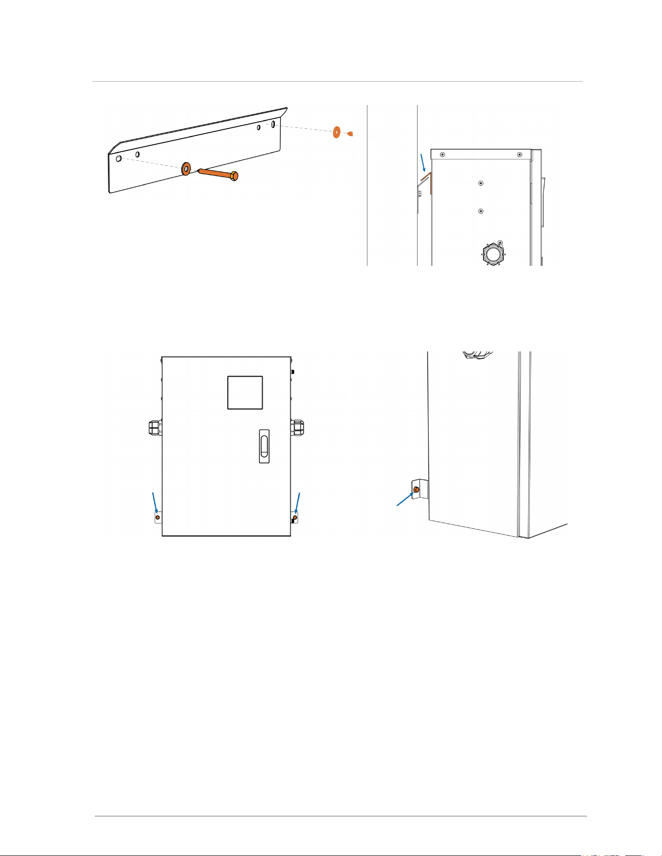
1.
Attach the support bracket to the wall studs
using two ¼" x 2½" long lag screws with
flat washers.
2.
Hook the boiler tab (located on
back of boiler) over the support
bracket flange. Ensure that the
boiler tab is flush against the
mounting bracket flange.
3.
Secure the lower part of the boiler to the
wall with two field-supplied ¼" bolts.
4.
Profile view of the lower
mounting flange.
15
6.4 Mounting the boiler
6.5 Installation clearances
Warning
Exposed water piping and associated components (relief valves, circulators, etc.,
should not be in contact with combustible materials. Check local codes for required
clearances and / or provide adequate insulation.
Electric Boiler Clearances
Surface
Minimum distance from combustible
surfaces
Recommended clearance
for installation and
service
Front 2" 24"
Left side 2" 4" (allow access to water
connections)
Right side 2" 4" (allow access to water
connections)
Top 2"
8" (to allow access to
elements)
Bottom 2" 6" (for drain and power
supply access)
Table 3 Clearance distances for boiler mounting sites
6.6 Closet installations
For installations in a confined space (such as a closet), ventilation openings may be needed
through a door or wall to prevent excessive heat from building up inside the space.
The appliance must not be exposed to surrounding air above 122°F (50°C) or below 32°F (0°C).
6.7 Water Piping
Using unions on the inlet and outlet water connections is strongly recommended; failure to use
unions may significantly complicate service and troubleshooting. Unions simplify many service
procedures, notably the cleaning of the inlet water strainer. See Installation on page 13 below for
other piping recommendations.
16
Section: Installation
Warning
Water quality has a significant impact on the lifetime and performance of a boiler's heat
exchanger.
Improperly prepared water in a heating circuit may cause damage to the heat exchanger
through fouling or corrosion. Repeated or uncontrolled water fills will increase the
potential for damage.
High levels of dissolved solids or minerals may precipitate out of the fluid onto the hottest
part of the heat exchanger, impairing heat transfer and resulting in overheating and
premature failure. The amount of solids that may form on the heat exchanger will depend
on the degree of hardness and the total water volume in the system. A high water volume
system with a low hardness count may cause as much damage as a system with less
volume and higher hardness, so it is recommended to treat water so as to reduce
dissolved solids to the minimum 10 ppm, and to no more than 30 ppm. Water chemistry
allowable limits are as follows:
TDS 0.6 to 1.75 grains/ gal (10 to 30 ppm)
Acidity pH is to be between 6.6 and 8.5
Chloride is to be less than 125 mg/l
Iron is to be less than 0.3 mg/l
Cu less than 0.1 mg/l
Conductivity is to be less than 400μS/cm at 77°F (25°C)
Important: Ensure that these limits are acceptable for the other water-side components
in the system.
17
6.7 Water Piping
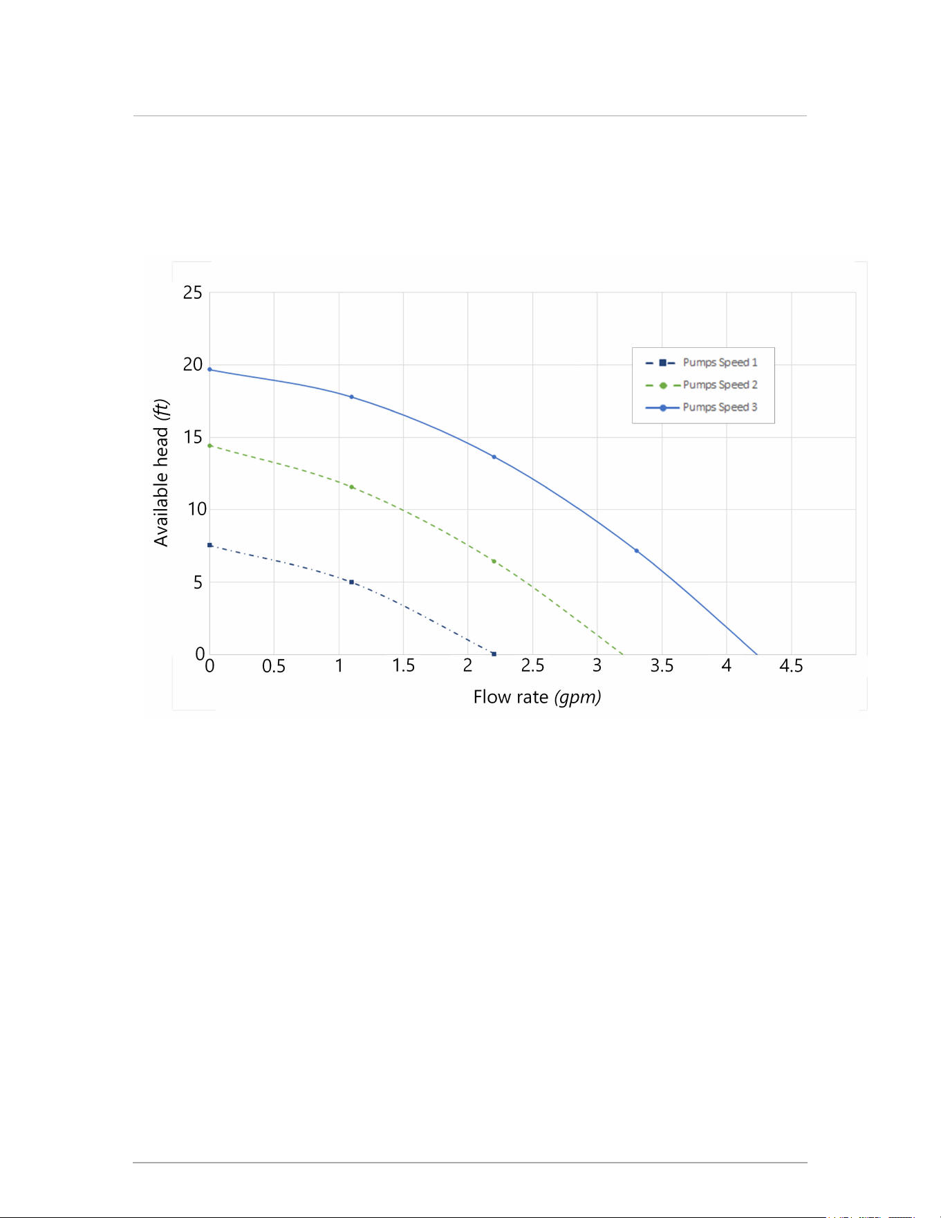
6.8 Boiler Pump
The factory-installed boiler pump can overcome the system head resistances listed below,
according to the selected speed:
Table 4 Electric boiler pump available head, 3 speeds (water)
The installed pump is rated for the designed water temperature range; some pumps have a
minimum water temperature rating above the low temperature potential of the boiler.
18
Section: Installation
6.9 Propylene glycol usage
Warning
Do not use automotive-type ethylene or other types of automotive glycol antifreeze, or
undiluted antifreeze of any kind. This may result in severe boiler damage. Installers must
ensure that glycol solutions are formulated to inhibit corrosion in hydronic heating
systems of mixed materials. Improper mixtures and chemical additives may cause
damage to ferrous and non-ferrous components as well as non-metallic, wetted
components, normally found in hydronic systems. Ethylene glycol is toxic, and may be
prohibited for use by codes applicable to your installation location. For environmental and
toxicity reasons, we recommend using only non-toxic propylene glycol.
Propylene glycol solution is commonly used in a closed loop where freeze protection is required. Its
density is lower than that of water, resulting in lower thermal performance at a given flow and
pressure. Generally, a 50%:50% solution of propylene glycol and water requires an increased
system circulation rate (gpm up 10%), and system head (up 20%) to provide performance equivalent
to straight water. Propylene glycol concentrations between 25% and 50% are permitted.
These boilers are designed for use within a closed loop, forced circulation, low pressure system. A
30 psi pressure relief is supplied for field installation on the outlet piping. Relief valve discharge
piping must terminate between 6" (15 cm) and 12" (30 cm) above the floor or per local code.
Warning
During operation, the relief valve may discharge large amounts of steam and/or hot water.
To reduce the potential for bodily injury and property damage, install a discharge line that:
Is connected from the valve outlet with no intervening valve and directed
downward to a safe point of discharge.
Allows complete drainage of both the valve and the discharge line.
Is independently supported and securely anchored, so as to avoid applied stress
on the valve.
Is as short and straight as possible.
Terminates freely to atmosphere where any discharge will be clearly visible and is
at no risk of freezing. terminates with a plain end which is not threaded.
Is constructed of a material suitable for exposure to temperatures of 375° F or
greater.
Is, over its entire length, of a pipe size equal to or greater than that of the valve
outlet (¾" NPT).
Do not cap, plug or obstruct the discharge pipe outlet.
19
6.9 Propylene glycol usage

6.10 Relief Valve
Ensure that the pressure relief valve is installed with no valves or other means of isolation
between its inlet and the boiler.
Make sure the relief valve outlet is piped with unobstructed piping (minmum 3/4" diameter) to a
safe discharge location.
6.10.1 Pressure Gauge
The boiler does not include a water pressure sensor. Field piping should always include a water
pressure gauge or a tridicator.
20
Section: Installation
6.11 General piping best practices
Primary/secondary piping, or the use of a hydraulic separator, is recommended for maximum
flexibility in multi-load applications. Piping loads in parallel is also encouraged in systems that only
have two loads, or when loads are operating simultaneously.
Caution
Contact local water purveyors about the suitability of the supply for use in hydronic
heating systems. If unsure about water quality, bring water or hydronic fluid of known
quality to the site. Alternatively, request testing and assessment (and treatment, if
required) from a local water treatment expert.
Note
The piping drawings in this manual are simple schematic guides to a successful
installation. There are many necessary components not shown, and details such as
thermal traps are left out so the drawings have greater clarity. Our boilers must be
installed by licensed and experienced heating professionals familiar with the
applicable local and national codes. System design is to be completed by an
experienced hydronic designer or engineer. You should carefully read and follow the
installation instructions along with the application drawing that fits your system.
System piping is connected to the boiler using 3/4" NPT-Male threaded fittings. To simplify
servicing, we recommend using unions at the boiler's supply and return water connections. A
union is necessary to clean the inlet mesh filter.
21
6.11 General piping best practices
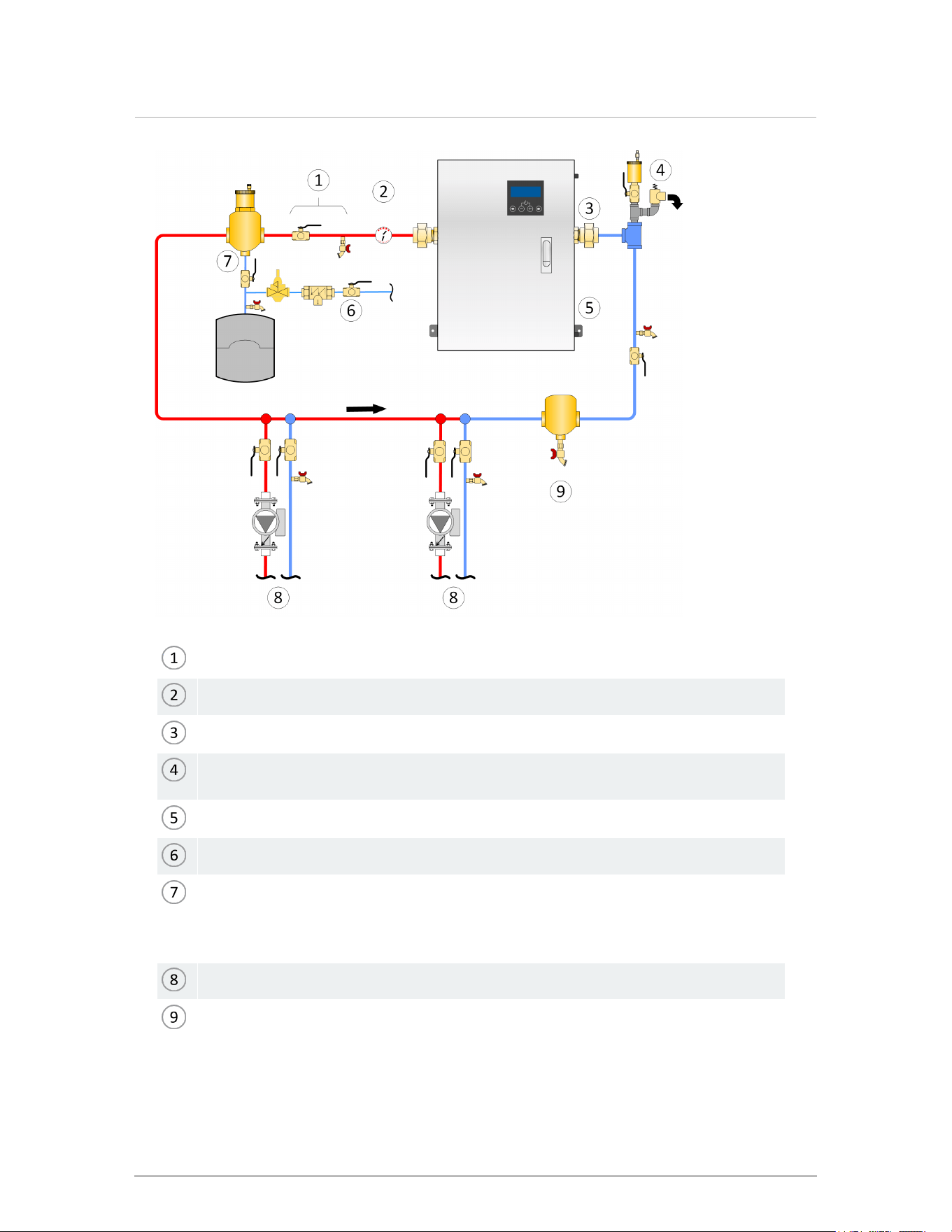
Isolation valve and hose bib for purging air from boiler
Water pressure gauge
A union is necessary to clean the inlet mesh filter
Pressure relief valve (shipped with the boiler): no isolation valve permitted between
boiler and relief valve
Boiler (primary) pump is integral to boiler
Fill station with isolation valve closed, or fill tank.
Microbubble air eliminators are best installed where the fluid is at the highest
temperature and lowest pressure, on boiler outlet at expansion tank connection (point
of no pressure change); there should be minimal pressure drop to pump inlet (in this
case boiler inlet)
To/ from load
Dirt separator (shown) or external strainer (P-913) recommended
Figure 7 Boiler trim options - single boiler
22
Section: Installation
Fluid fill is most often accomplished by using a boiler regulator and fill valve set at 12 psig or
higher, with the backflow prevention device required by local code. This is acceptable in areas
where municipal water or well water has been treated and filtered to remove excessive minerals
and sediment, and water chemistry is known to be suitable for closed loop hydronic systems.
Follow the applicable codes and good piping practice.
Warning
Close the fill valve after any addition of water to the system, to reduce risk of water
escaping.
In areas where water quality is in question, or when chemical treatment or glycol is required,
other options should be considered. Today there are a number of boiler feed and pressurization
devices on the market that may be a better choice than a raw water fill from the mains. When
regular maintenance requires relief valve blow-off, the discharge may be directed back into the
pressurization appliance for recycling of boiler fluid and chemicals back into the system. In
buildings that may be unoccupied for long periods of time, pressurization appliances are useful
to prevent flood damage should leakage occur from any component in the system. An additional
benefit is that backflow prevention devices are not required when using these devices.
To avoid damage to controls, do not place any water connections above the boiler . If needed,
create a shield over the top of the cover, but allow clearance for airflow and service access.
6.11.0.1 Primary-Secondary piping
For best results, use a primary/secondary piping system, with a pumped boiler loop using 1" or
1¼" piping. Primary/Secondary piping ensures adequate flow and de-couples ΔT issues (boiler
vs. distribution). Aim for a 10-20°F ΔT (6-11°C) across the boiler at full output.
Check valves or thermal traps should be used to isolate both the supply and return piping for
each load - to avoid thermal siphoning and reverse flow.
23
6.11 General piping best practices
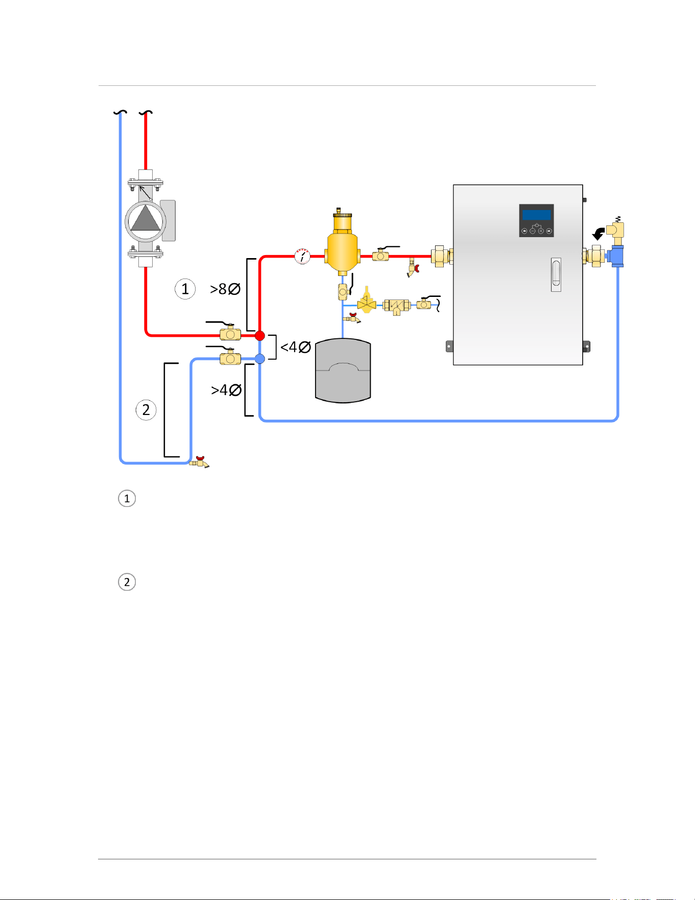
Closely-spaced tees: Install tees a maximum of four pipe diameters apart with no
restrictions between fittings, and with a minimum of eight pipe diameters of straight
piping upstream of the first tee and a minimum of four pipe diameters of straight
piping downstream of the second tee.
Heat Migration—on secondary loops that extend vertically to a load that is above the
primary loop, steps must be taken such as fabricating a thermal trap in the return
piping –minimum 18" (46cm) drop– to prevent thermal siphoning and heat migration
to the load when there is no demand for heat to that loop. Alternatively, use check
valves on both supply and return of secondary piping.
Figure 8 Primary-secondary piping details with closely-spaced tees
24
Section: Installation
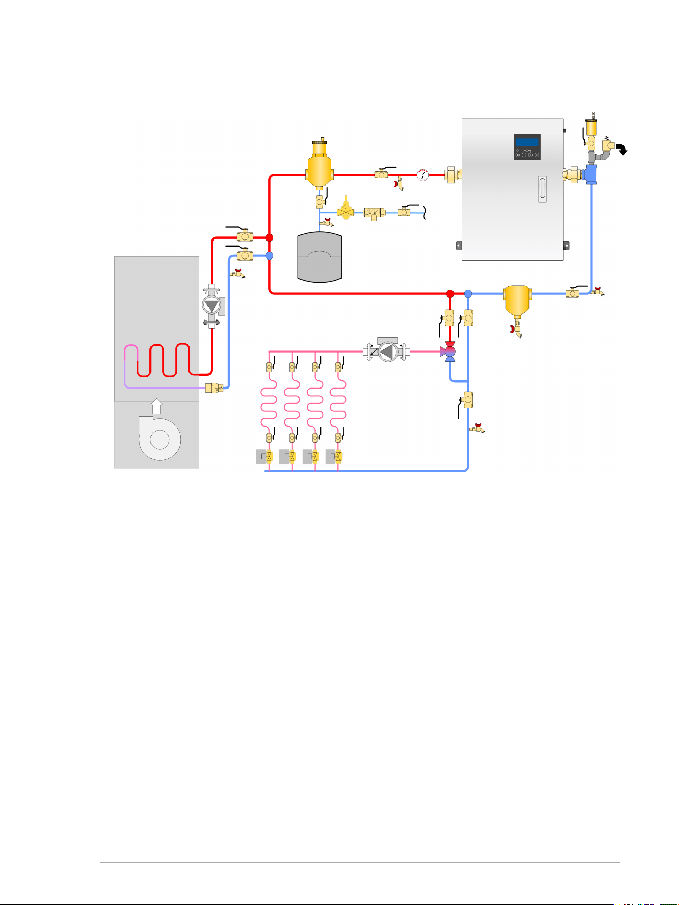
Figure 9 Primary-secondary piping with simultaneous heating calls
The boilers can supply multiple heating loads with compatible supply temperature requirements.
Always ensure that loads sensitive to high temperatures are protected using means such as
mixing valves.
25
6.11 General piping best practices
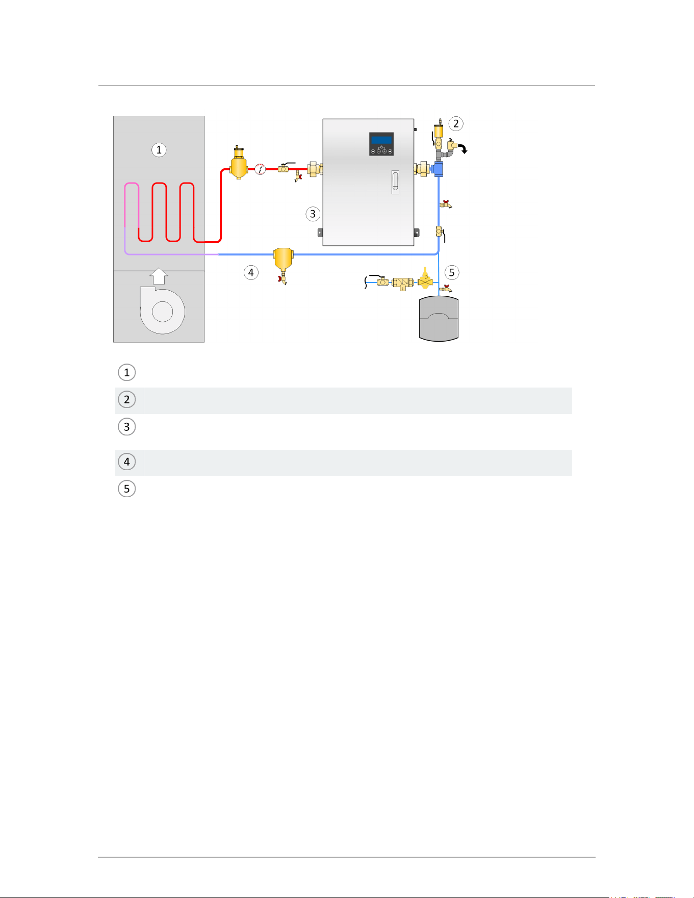
Air handler with low head loss coil
Pressure relief valve—no isolation valve between relief and boiler
Pump integral to boiler must be verified capable of overcoming combined pressure
drops of boiler, system piping, and air handler coil
Dirt separator recommended where water quality is unknown
Expansion tank connection point between air handler coil and boiler inlet
Figure 10 One load direct piping concept
26
Section: Installation
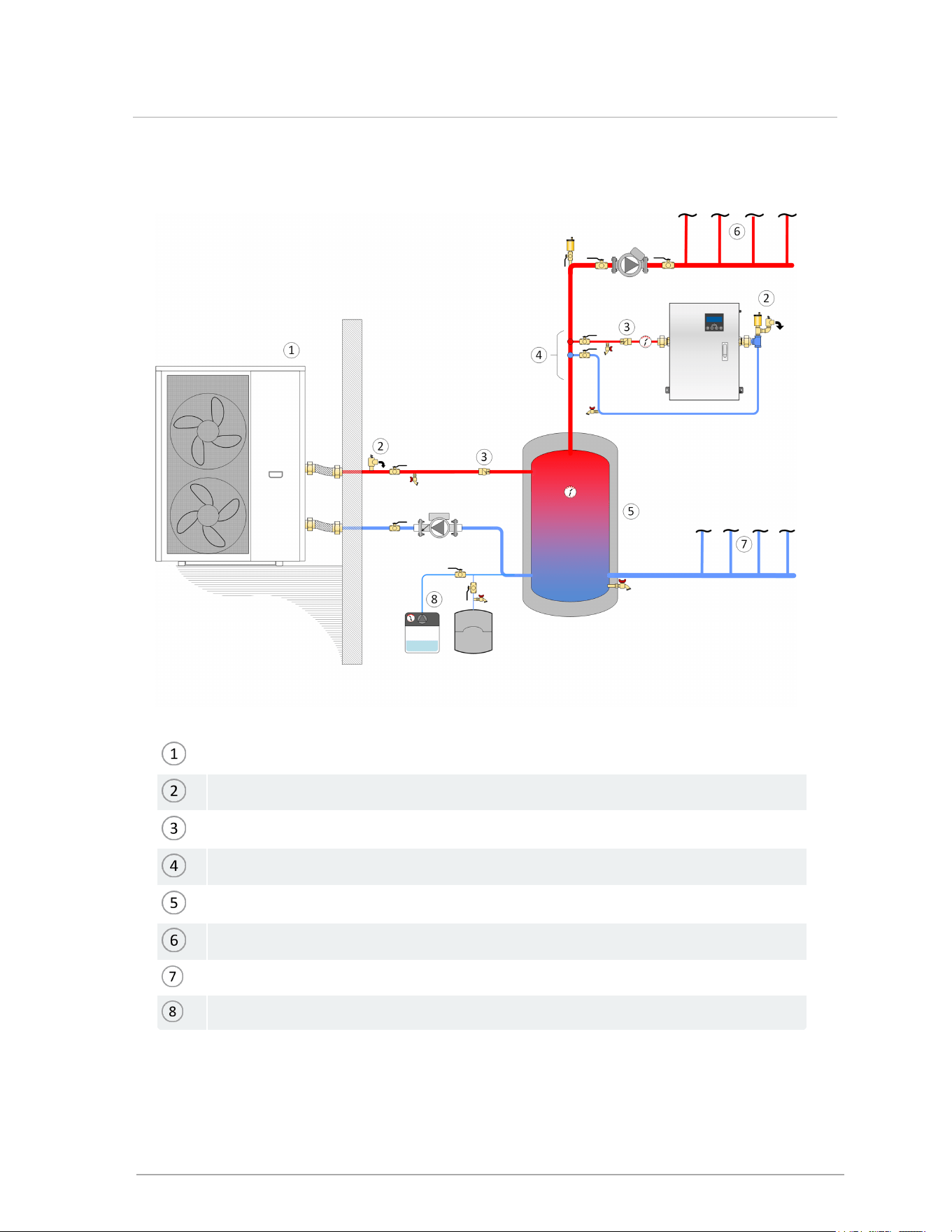
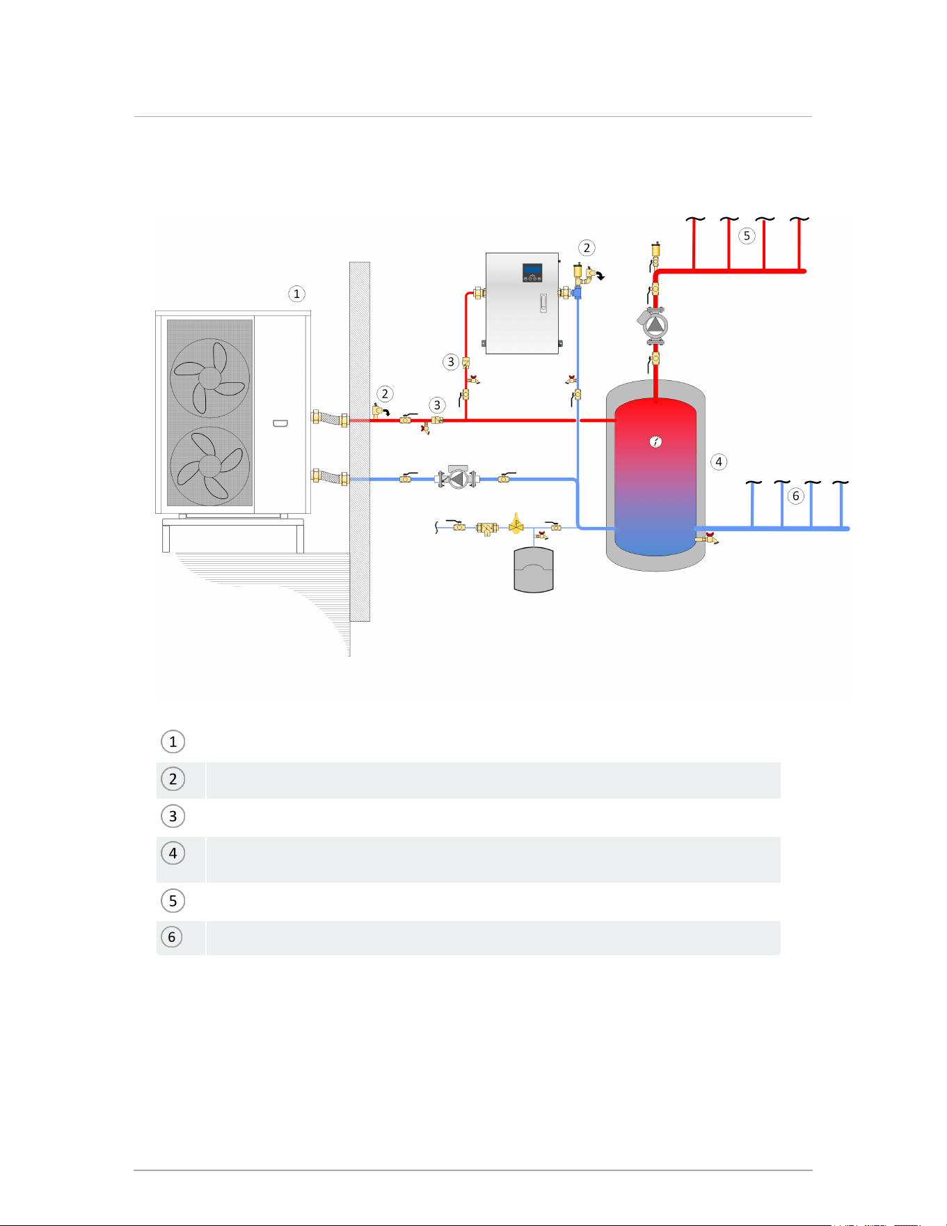
Electric boilers can supply 'top-up' heat for a primary heat source, such as a heat pump as shown
below. The call for backup may come from the primary source, or from third-party controls.
Heat Pump boiler (shown without integral pump)
Relief valve
Check valves
Closely-spaced tees
Generously sized buffer tank connections hydraulically separate heat pump from loads
Supply manifold
Return manifold
Glycol fill tank
Figure 11 Heat pump boiler and backup electric boiler
27
6.11 General piping best practices
The following drawing allows the designer to benefit from electric utility variable rates and for
example have a boiler raise the buffer tank temperature overnight:
Heat Pump boiler (shown without integral pump)
Relief valve
Check valves
Generously sized buffer tank connections hydraulically separate heat pump from
loads
Supply manifold
Return manifold
Figure 12 Heat pump boiler and backup electric boiler serving heat loads through a buffer tank--
variable metering option
28
Section: Installation
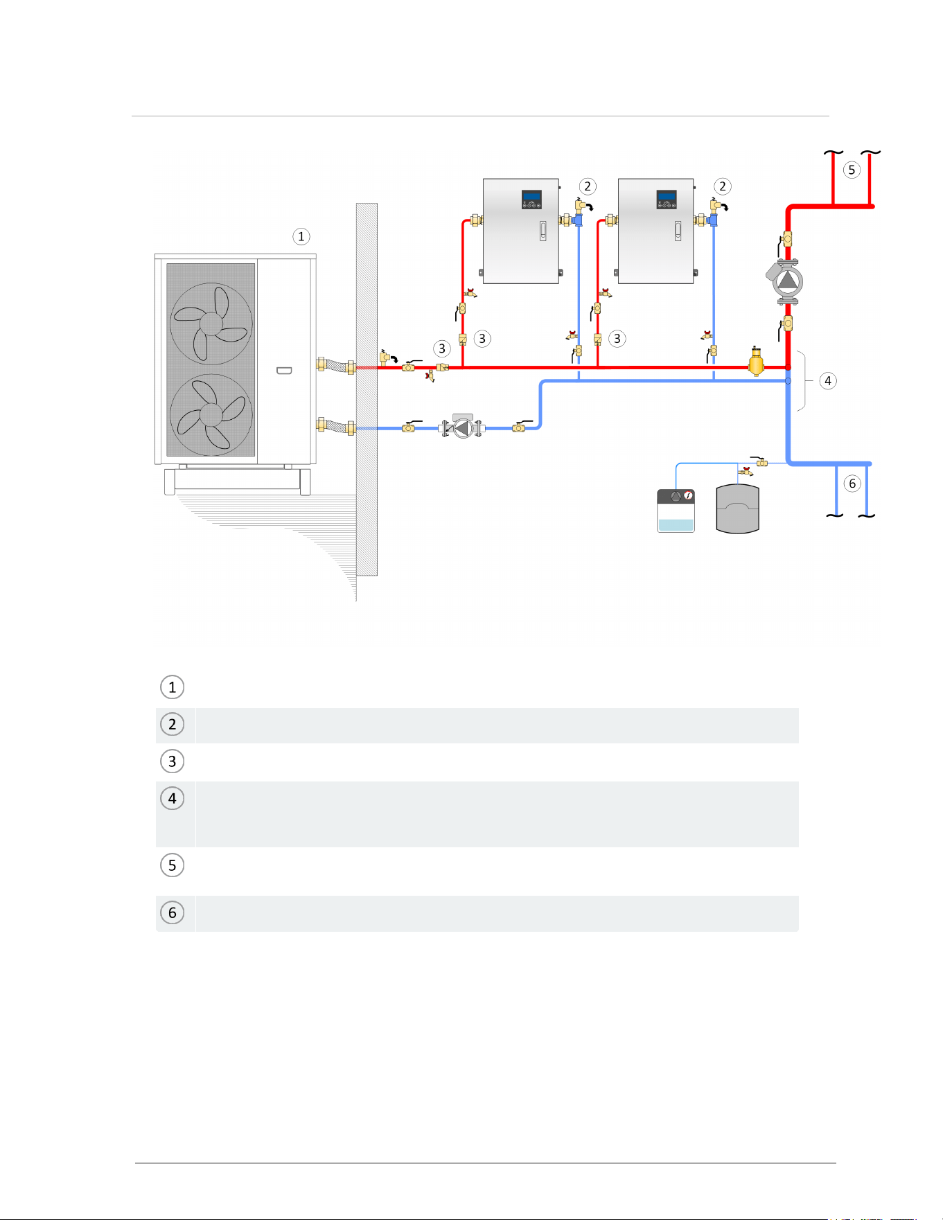
Heat Pump boiler; system fluid circulates outdoors so typically requires glycol treatment.
Electric boilers staged to supplement heat pump below system balance point.
Check Valves
Closely-spaced tees are a maximum of four pipe diameters apart, with a minimum of
eight pipe diameters of straight piping upstream of the first tee and a minimum of four
pipe diameters of straight piping downstream of the second tee.
Supply to Heating System: heat pump piping without buffer tank requires that every zone
have a large thermal mass.
Return from Heating System: see above.
Figure 13 Multiple boiler piping
29
6.11 General piping best practices
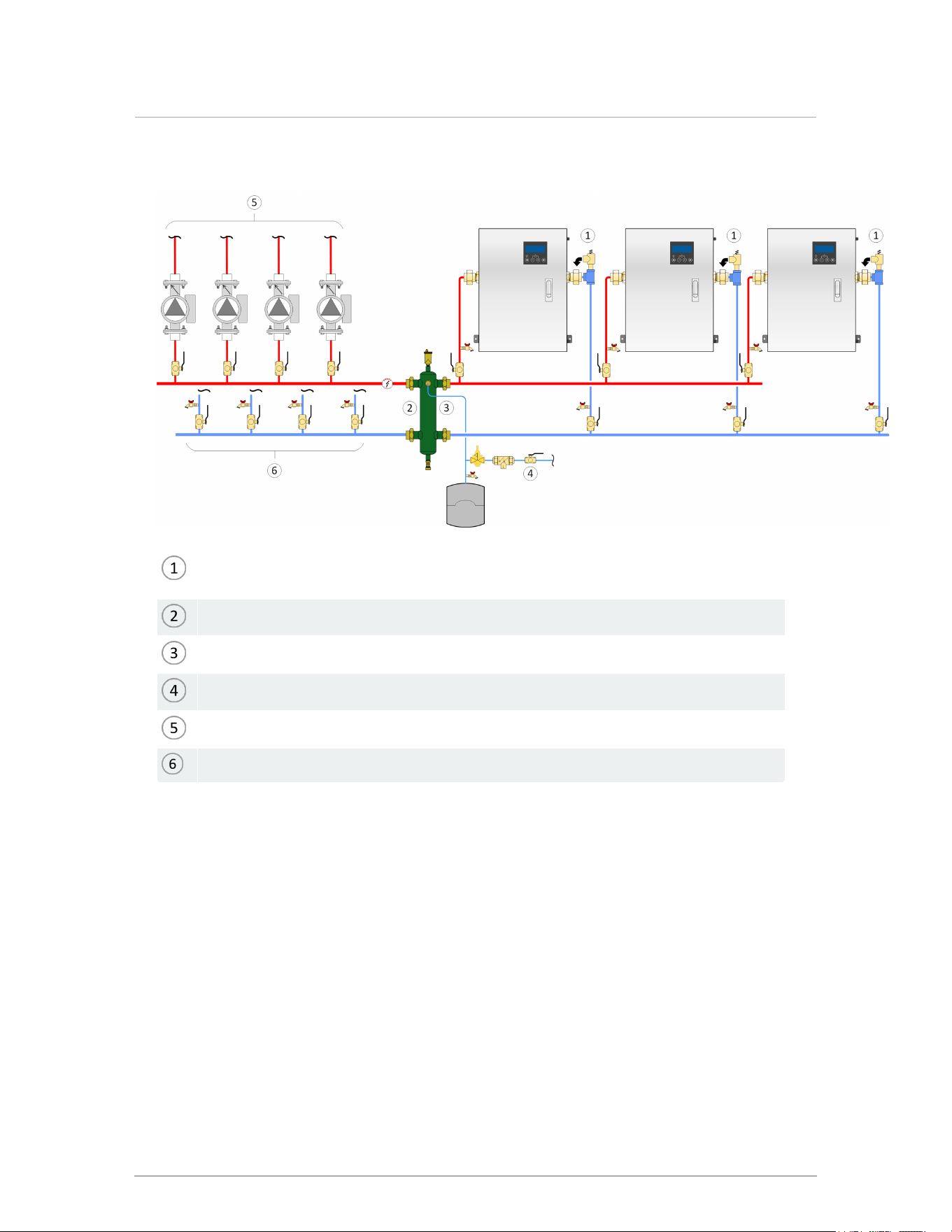
Multiple-boiler installations will require an external controller .
Pressure relief valve (shipped with boiler): no isolation valve permitted between boiler
and relief valve
Hydraulic separator
Recommended expansion tank connection point
Fill station with isolation valve closed, or fill tank
Supply piping to loads
Returns to loads
Figure 14 Primary-Secondary multiboiler piping concept with hydraulic separator
30
Section: Installation
6.12 Electrical connections
All electrical wiring to the boiler (including grounding) must conform to local electrical codes and/or to
the National Electrical Code, ANS/NFPA No. 70 – latest edition, or to the Canadian Electrical Code,
C22.1 - Part 1.
Warning
CAUTION:A.C. ONLY, USE COPPER WIRE ONLY. DO NOT USE ALUMINUM
6.12.1 Power management, quality and electrical protection
In areas of unreliable power, appropriate surge protectors and or power conditioning equipment
should be installed in power supply wiring circuits.
Note
These boilers (like any modern appliance that contains electronic equipment) must have
a “clean” power supply, and is susceptible to power surges and spikes, lightning strikes
and other forms of severe electrical “noise”. Power conditioning equipment (surge
protectors) may be required in areas where power quality is suspect.
In temporary or manual operation, for example in new construction heating, use a construction
thermostat or jumper with an in-line switch for on/off management of the boiler. Do not turn off the
heat by removing power to the boiler as this interrupts the pump post-purge.
6.12.2 240VAC line-voltage hook-up
Line-voltage wiring is done within the field-wiring box (see Wiring diagrams on page 1). Connect the
boiler to the grid power using a separate, fused circuit and on/off switch within sight of the boiler. Use
appropriately-sized wire in conduit or metallic sheath properly anchored to the boiler case for mains
supply and pump circuits.
31
6.12 Electrical connections
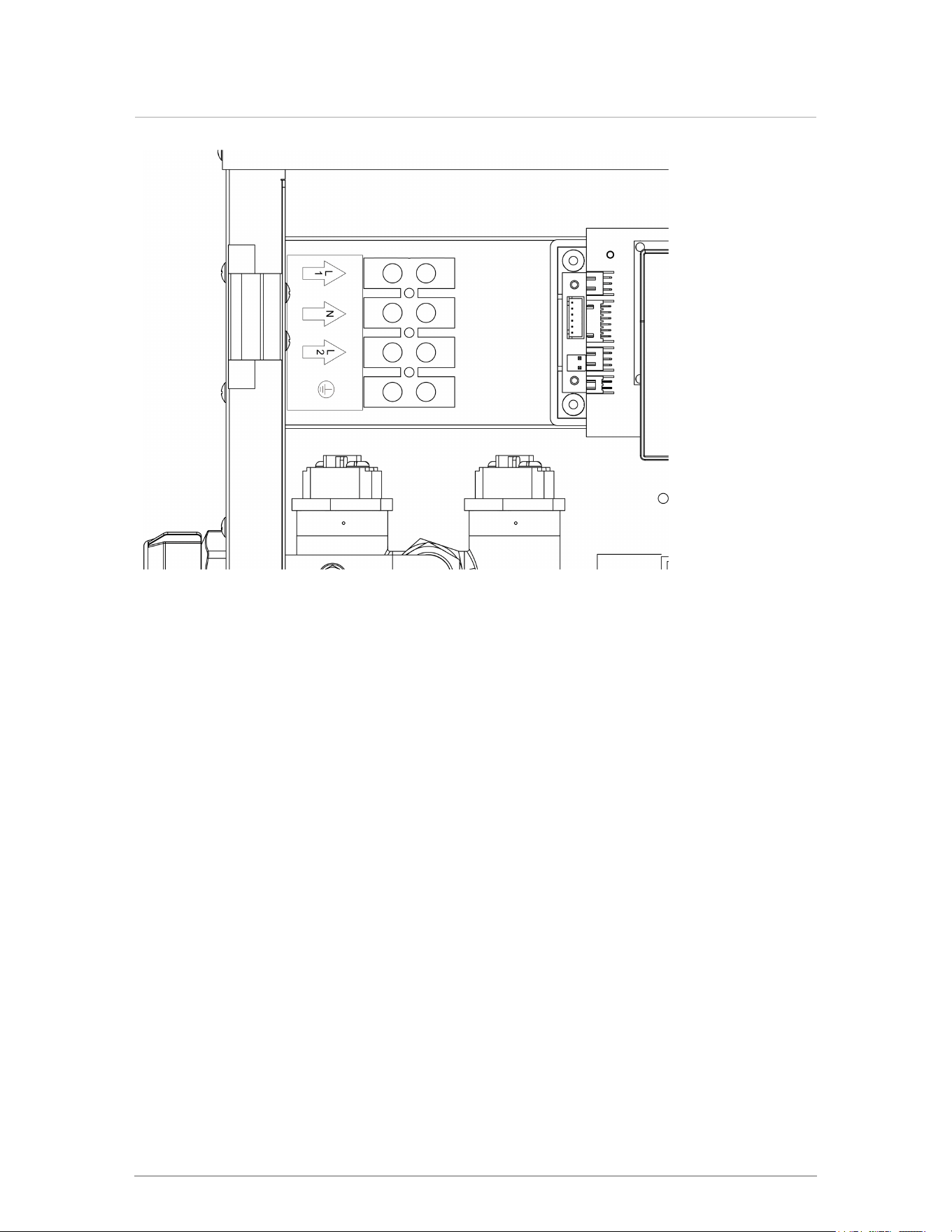
Figure 15 Line voltage load pump terminals
The Neutral connection is necessary for 120V operation of the boiler pump.
6.12.3 Boiler pump
The boiler pump is factory installed and wired. It has three speeds to choose from. The installer
may adjust the speed setting to best match the system requirements. See section 3.8 for boiler
pump curve chart.
6.12.4 Thermostat wiring
Thermostat-type control wiring will go to the three terminals of the CN2 block; these are labeled
"VAC24-R / VAC24-W / VAC24-C"). Closing a dry contact between terminals 1 and 2 (VAC24-R
& W) initiates a call for heat.
For a load with multiple zones (e.g. thermostats controlling zone valves), wiring the end-
switches of each zone valve in parallel to terminals 1 and 2 presents a common thermostat
signal to the controller.
Ensure that there are no disturbing influences on the call-for-heat lines - for example, that there
are no coils to switch an air handler motor. Most power stealing thermostats can be connected
directly to the CN2 terminals.
32
Section: Installation
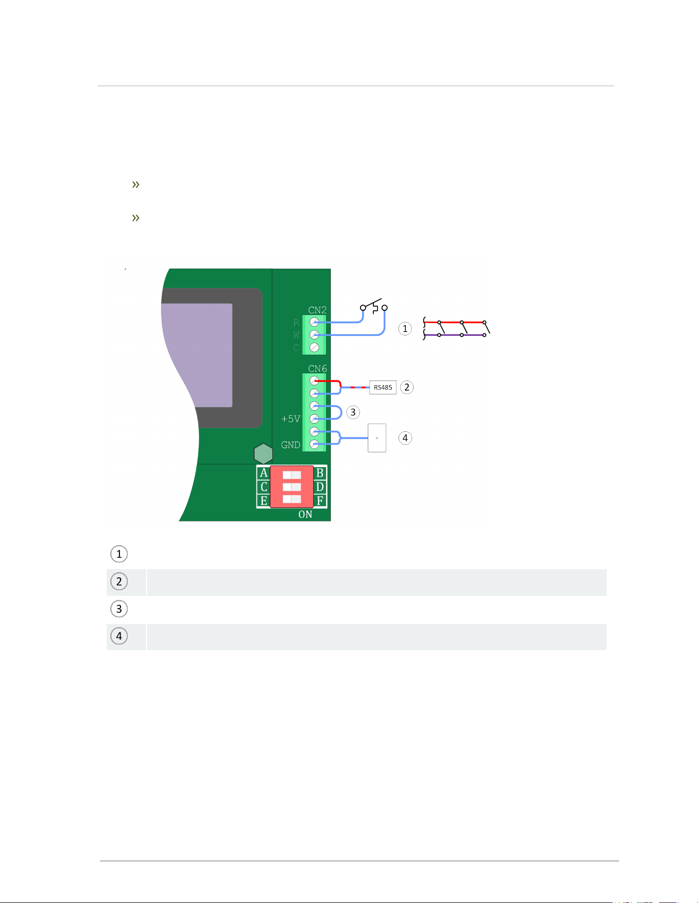
6.12.5 Other wiring
Other optional low voltage connections to the control board include:
An auxiliary Interlock at CN6 terminals 3 & 4- for external safety devices as may be required
by some jurisdictions, such as an external low-water cutoff.
Contacts for outdoor temperature sensor associated with reset heating at CN6 terminals 5 &
6. A 10K ohm sensor for outdoor reset feature is sold separately .
Thermostat, or zone valve endswitches parallel-wired (three shown)
RS485 connection for MODBus control*
Jumper, or to dry contact on external safety device (interlock)
Outdoor temperature sensor, located on North exterior of building
*The dipswitches set MODBus addresses only and do not affect normal operation.
Figure 16 Thermostat, interlock and outdoor sensor field wiring
6.12.6 Load pump wiring
The electric boiler does not control load pumps. For load pump control use a third-party pump
module , or field-wiring a double-pole relay, as shown here:
33
6.12.5 Other wiring
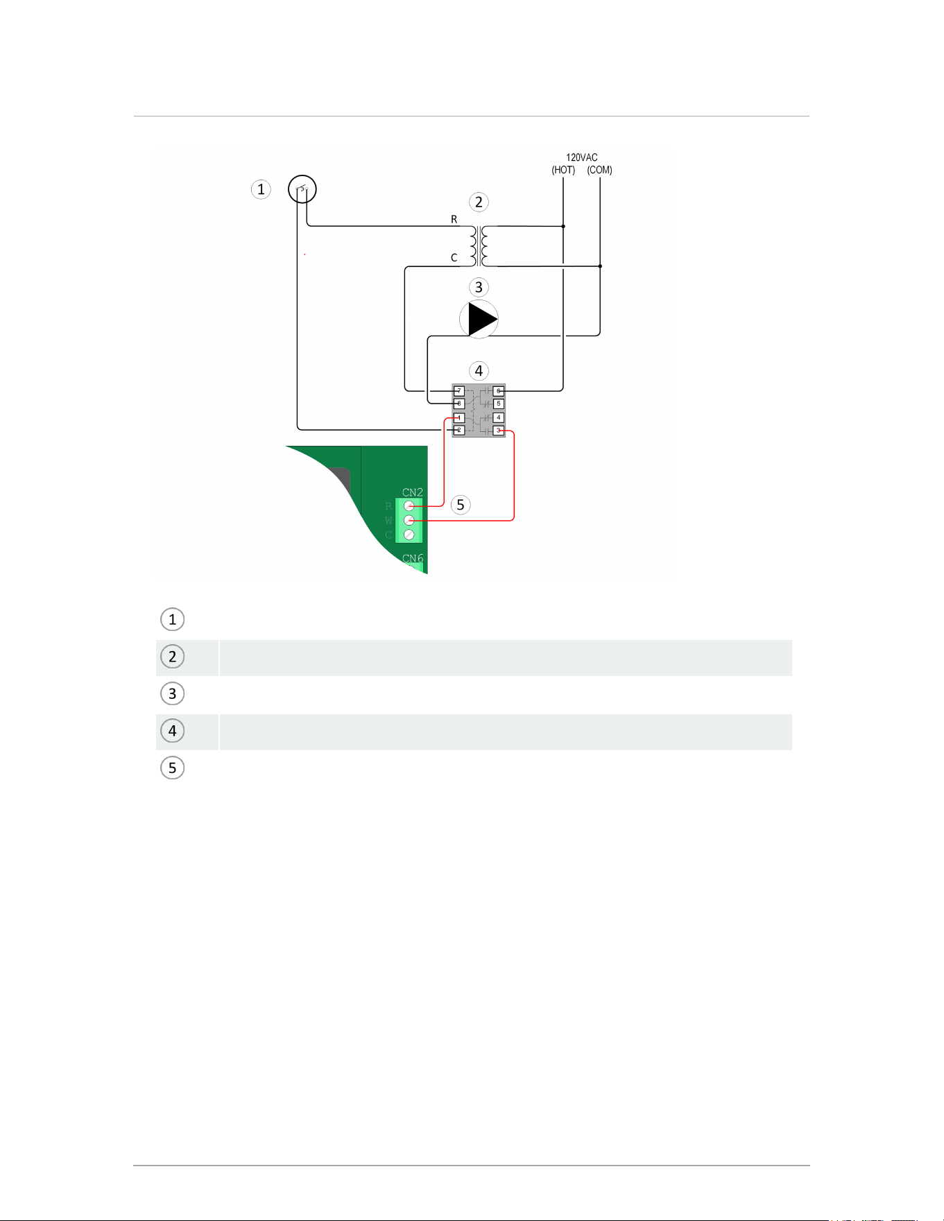
Thermostat
24V Transformer
Space-heating pump
24V double pole relay: can be DPDT (shown) or DPST
Call for heat to boiler CN2 terminals 1 and 2
Figure 17 Load pump relay field-wiring
This wiring can be expanded to use multiple zone valves, as shown here:
34
Section: Installation
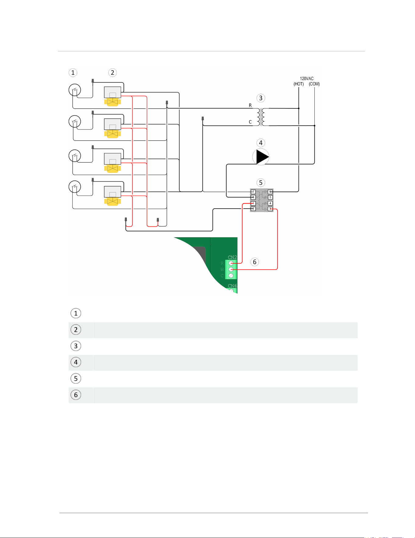
Thermostats
Zone valves (four-wire type shown; 3-wire also applicable here)
40VA Transformer; typically adequate for up to four zone valves
Space-heating pump
24Vdouble pole relay: can be DPDT (shown) or DPST
Call for heat to boiler CN2 terminals 1 and 2
Figure 18 Load pump relay field-wiring with zone valves
Alternatively, using a pressure-activated load pump may make pump control unnecessary.
35
6.12.6 Load pump wiring

7.0 About the boiler controller
Note
Use a finger to interact with the controller buttons.
The controller provides:
Home Page display of the Target, Outlet and Inlet temperatures
Status Page displaying Output power (in %)
Set-Point temperature regulation
Easy-to-set Outdoor Reset control
Heat Enable from Thermostat
Error Message Reporting
Warning Message Reporting
Unit selection for °F or °C
7.1 Controller
When the boiler is first energized, the controller will go through a brief power up sequence. During this
time the controller is completing a self-diagnostic and loading all previous settings. In the event of a
power interruption the boiler will automatically resume operation when power is restored with all the
previously stored values.
The controller provides overall management of the boiler operations including:
Power-up and self-diagnostics
Safety management systems, call-for-heat management
Real time boiler data
Temperature and throttle operation. The variable power level will be based on the flow rate
measured and the required outlet temperature.
36
7.0 About the boiler controller
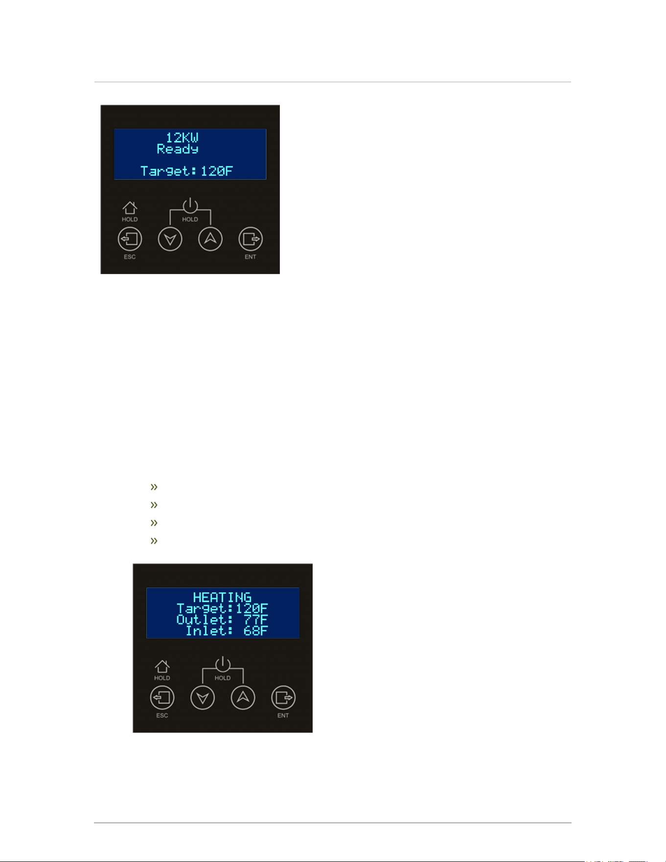
Figure 19 Controller screen and navigation buttons
7.2 Control interface
The control interface is provided through four navigation buttons which respond to a light finger
touch, and a display screen.
Prior to any interaction with the control, the Home Page shows the current boiler status.
The control has three levels:
1. Home Menu
Status: Ready, Heating, Circulating, Warning or Error
Target [temperature]
Outlet [temperature]
Inlet [temperature]
37
Section: About the boiler controller
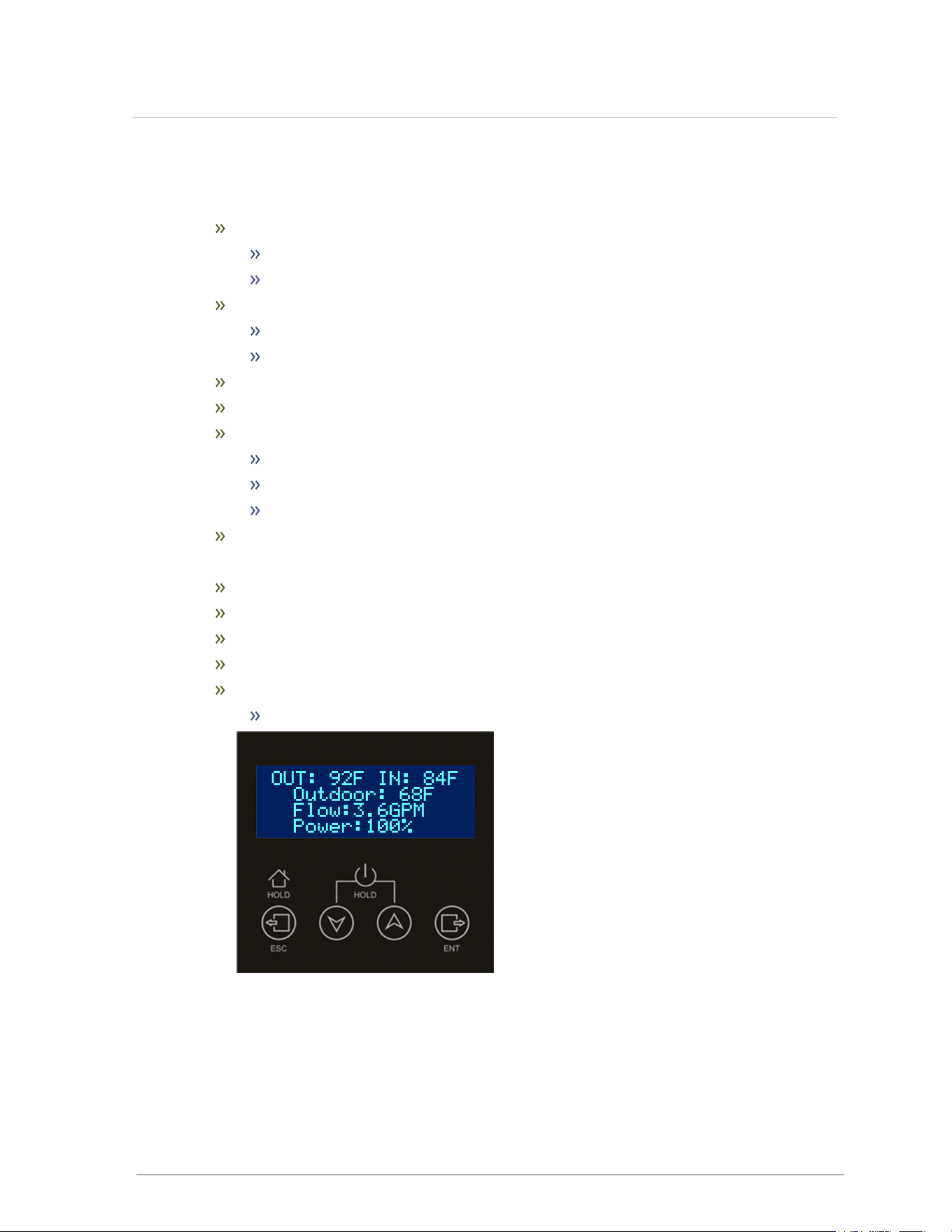
Figure 20 Controller Home screen
2. Settings Menu
Setpoint T.
range: 68°F to190°F (20°C to 88°C)
default: 120°F (48.9°C)
Outdoor Design T.
range: -31°F to 59°F (-35°C to 15°C)
default: 10°F (-12.2°C)
Heat Type: Setpoint (SET) or Outdoor Reset (ODR)
Units: °F/°C
Summer Shutdown
range: 50°F to 104°F (10°C to 40°C)
default: 65°F (18.3°C)
Status is ON in ODR mode
Post-Purge Time: pump will run set number of seconds after a call
3. Status Menu
Outlet [Temperature]
Inlet [Temperature]
Outdoor [Temperature]
Power % (current output)
Faults and Warnings:press Enter for code with plain language description.
For warning codes see Troubleshooting error messages on page 1
Figure 21 Controller Status screen
The control automatically returns to the Home screen in 1 minute if no button has been touched.
If the controller is in an error state, the Error Code and an explanatory text will be displayed.
38
7.2 Control interface

If the controller has a warning to declare, the screen will rotate between the Home Screen and the
Warning(s), each displayed for 10 seconds. Warnings do not prevent operation.
7.2.1 Heat Types
The controller can be programmed for either of two Heat Types:Setpoint (SET) and Outdoor
Reset (ODR).
Note that if an outdoor sensor is connected and reports a temperature above the setting Summer
Shutdown, the boiler will not fire: it will stay in Ready mode and report E3:Summer Shutdown.
7.2.1.1 Setpoint (SET)
When Heat Type is defined as Setpoint, the setting Setpoint T is the water temperature the boiler
will target during a call for heat.
7.2.1.2 Outdoor Reset (ODR)
Outdoor Reset is a water temperature strategy for optimizing end-user comfort and building power
consumption. Outdoor reset modulates the water target temperature according to the outdoor
temperature, reserving the hottest water for the coldest weather.
When Heat Type is set to ODR, the controller needs only two variables defined: Setpoint T for the
hottest water and Outdoor Design T for the local climate's winter temperature. The graphs below
sample four Outdoor Design Temperatures to show how the target temperature tracks building
heat loss over a heating season.
For ODR mode, a 10KΩ outdoor sensor is necessary (sold separately). The sensor must be
mounted on the North face of the building , unaffected by heat sources, and above the anticipated
snow line.
If the boiler is in Outdoor Reset mode but an outdoor sensor is not attached, the boiler will operate
but flash a warning: see Troubleshooting warning messages on page 1.
39
Section: About the boiler controller
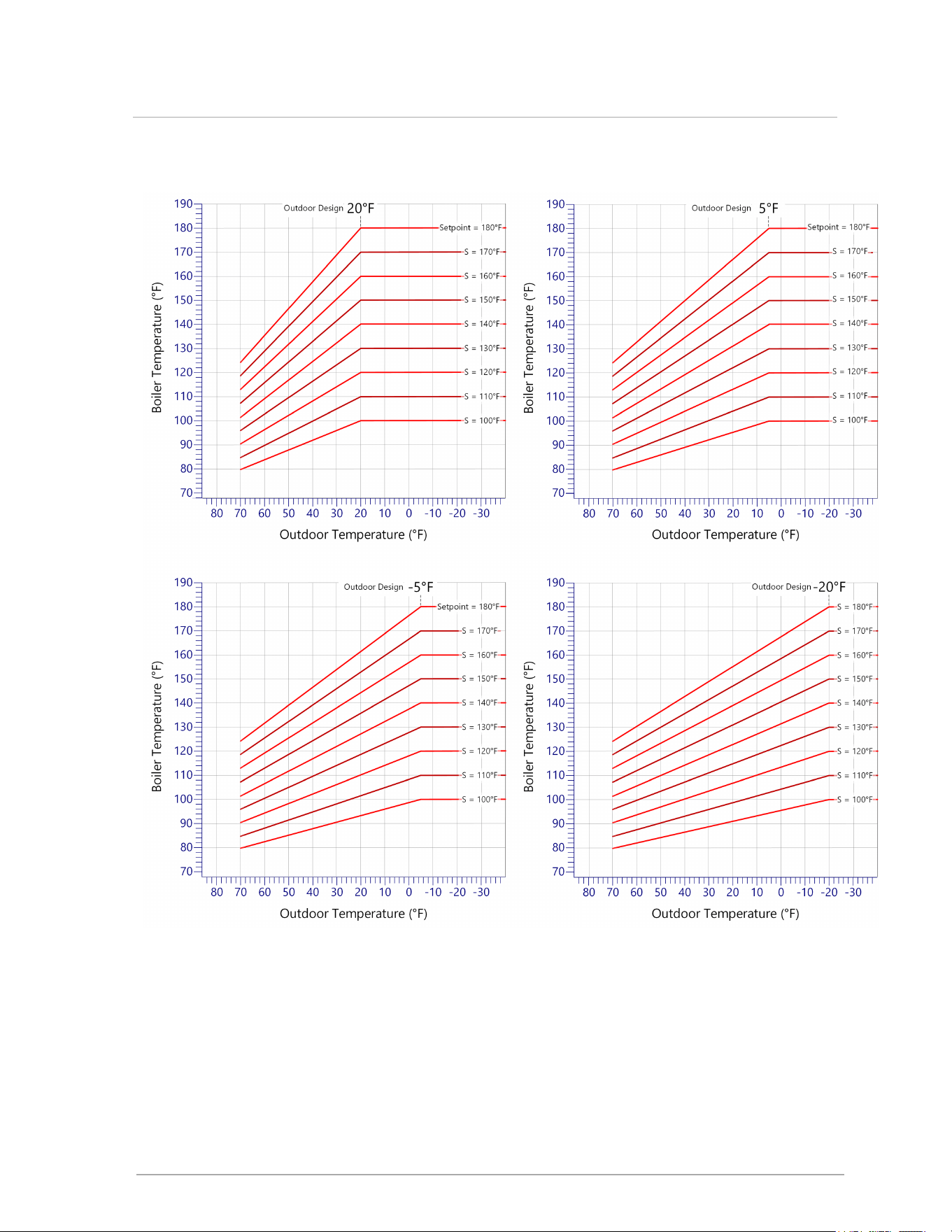
7.2.1.3 Sample ODR Temperatures:Imperial units
Figure 22 Outdoor reset lines for sample Outdoor Design Temperatures and Setpoints in Imperial units 100°F-
180°F
40
7.2.1 Heat Types
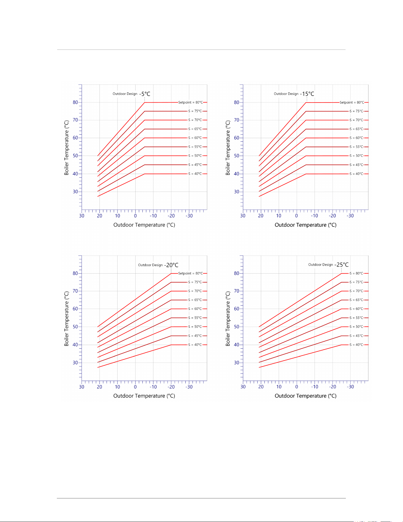
7.2.1.4 Sample ODR Temperatures:Metric units
Figure 23 Outdoor reset lines for sample Outdoor Design Temperatures and Setpoints in Metric units 40°F-
80°C
41
Section: About the boiler controller
8.0 Before operating the boiler
Danger
Do not store or use gasoline or other flammable vapors or liquids in the vicinity of this or
any other appliance. If you smell gas vapors, do not try to operate any appliance - do not
touch any electrical switch or use any phone in the building.
Do not use this boiler if any part has been under water. Immediately call a qualified service
technician to inspect the boiler and to replace any part of the system that has been under
water.
Checklist for electrical conditions and water connections
Checking electrical conditions Check
Check all line voltage electrical connections to ensure all connections are correct and
tight.
□
Check thermostat connections.
□
Thermostat in a suitable location.
□
Checking piping connections Check
All connections are pressure tested and leak free.
□
All piping flushed to ensure all air is removed.
□
Powering on the boiler Check
Perform a final check of electrical wiring, and provide power to the boiler to initialize
operation.
□
42
8.0 Before operating the boiler

9.0 Boiler operation
Before operating the appliance, there are some important checks that need to be performed. For
more information, see Before operating the boiler on page 1.
9.1 Starting and shutting down the boiler
Start-up Checklist Check
With the boiler power turned off, check that all electrical connections are tight.
□
Check with a gauge that the system pressure is stable and appropriate for the application:
at all times it should be between 8 psi and 50 psi.
□
A pressure relief valve must be installed on the system. A 30 psi relief valve is supplied.
□
Perform a thorough visual check for any leaks or signs of corrosion.
□
43
9.0 Boiler operation
10.0 Service and maintenance
Inspection of the boiler is to be performed annually by a qualified service technician.
Caution
The owner is responsible for general care of the boiler. Improper maintenance of the boiler
may result in a hazardous condition.
10.1 Maintenance checklist for homeowner
Maintenance Required Frequency Check
Inspect system for unusual noises. Call your local heating contractor for
service if needed
As needed
□
Keep combustible materials and flammable liquids and vapors away from
the boiler.
As needed
□
Inspection of the boiler is to be performed annually by a qualified service
technician.
Annually
□
Caution
Label all wires prior to disconnection when servicing controls. Wiring errors can cause
improper and dangerous operation.
44
10.0 Service and maintenance
10.2 Replacing the elements
Heating elements come in sizes 2kW for the 4kW model, 4kW for the 8kW model, 5kW for the
10kW model, and 6kW for the 12kW model. The elements can be replaced only by models of
identical wattage.
Figure 24 Element hex heads
Figure 25 Unscrew and lift out elements
1. Power off boiler and open cabinet door.
2. Close the water isolation valves and drain the boiler.
3. Remove and set aside the four screws of the cabinet lid. Remove the cabinet lid.
4. Label the element wires and disconnect them.
5. Unscrew the elements from the heat exchanger and lift straight upwards to remove.
6. Reassemble in reverse order.
45
Section: Service and maintenance
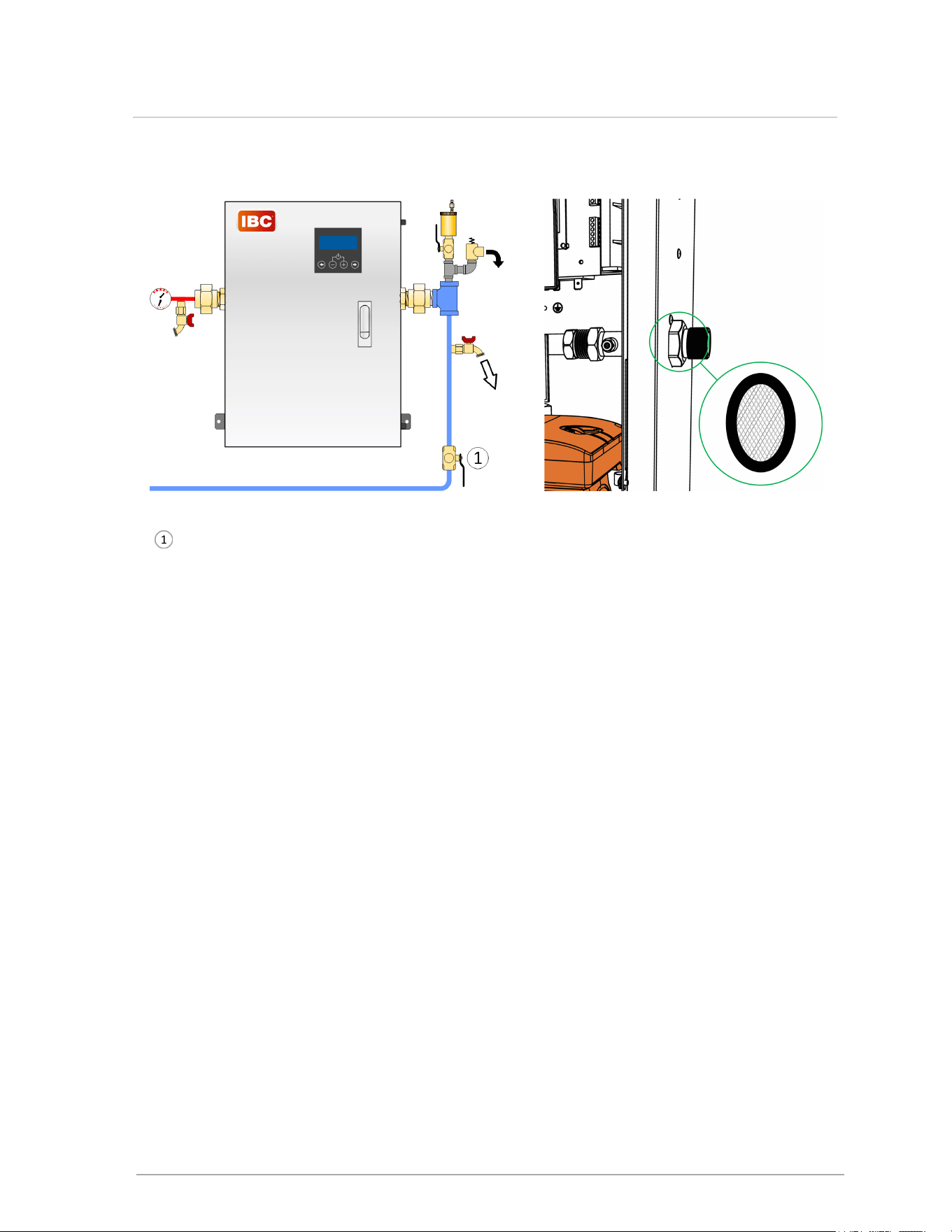
10.3 Cleaning the mesh filter
Valve closed during flushing (boiler powered
off).
Figure 26 Back-flushing to clean mesh filter
Figure 27 Inlet water connection-mesh filter inside
To clean filter, back-flush with the fittings shown above in Figure 26 . Alternatively, remove the filter to
clean it:
1. Power off boiler and open cabinet door.
2. Close the water isolation valves and drain the boiler.
3. Undo the union on the inlet connection.
a. If a union is not present, install one for future maintenance, or consider replacing the inlet
mesh filter with a serviceable strainer on the exterior of the boiler.
4. The mesh filter sits approximately one inch inside the inlet pipe: a rubber gasket holds it in
place by friction. Remove filter carefully with tweezers.
5. Flush the filter clean with water.
6. Reassemble in reverse order.
46
10.3 Cleaning the mesh filter
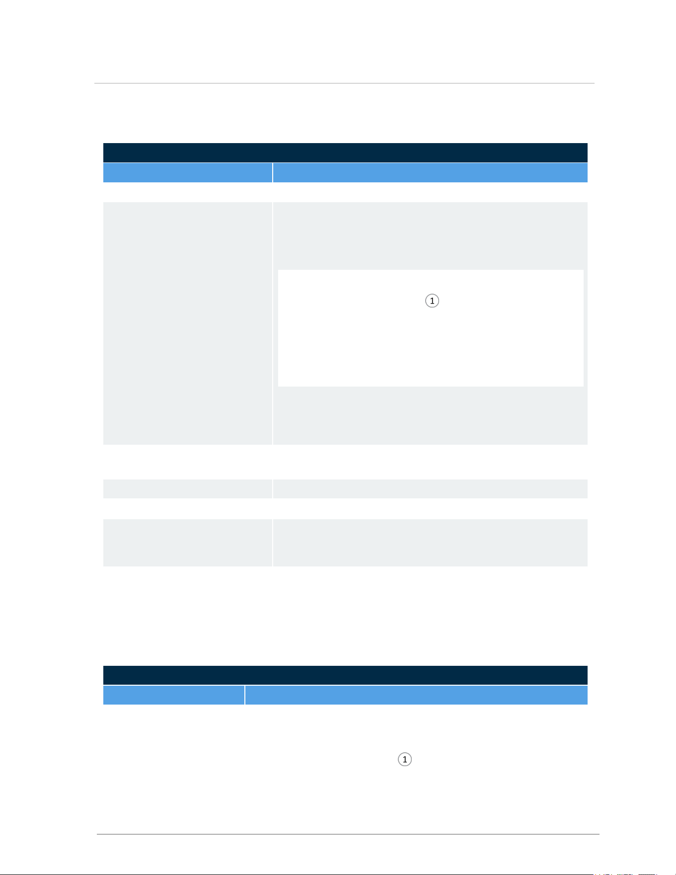
10.4 Replacing the pump
Figure 28 Remove bracket screws
Figure 29 Undo pump unions
Figure 30 Pull pump forward to disconnect wiring.
Figure 31 Remove bolts holding pump to bracket.
Re-use bracket.
1. Power off boiler and open cabinet door.
2. Close the water isolation valves and drain the boiler.
3. Remove the four screws to the pump bracket on the cabinet underside.
47
Section: Service and maintenance

4. Undo the two union nuts on the pump volute.
5. Slide the pump on its bracket forward enough to access the wiring box: prevent the pump from
falling forward and pulling on its wiring harness.
6. Disconnect the wiring harness.
7. Remove the pump and bracket. Inspect gaskets carefully, or replace.
8. Remove the bolts holding the pump to the bracket and transfer the bracket to the new pump.
9. Reassemble in reverse order.
48
10.4 Replacing the pump

11.0 Troubleshooting
This section includes various conditions as well as possible solutions. Often, a problem can be
identified and solved through basic checks: confirming the electrical power supply and resetting the
thermostat control. Below are some common troubleshooting issues including fixes.
1. Preliminary Checks
a. Confirm power to the boiler:check that the display is lit.
b. Check that the boiler is not in a safety lockout.
c. Ensure wiring is clean and secure.
d. Confirm that the water pressure is within specifications.
2. Electronics Components Checks
a. See sections on checking the status of various control circuit components such as:
i. Temperature sensors
ii. Water flow sensor
iii. Water high limit switch
3. Symptoms, Diagnoses and Fixes
a. See sections covering diagnoses and fixes including:
i. Cycling
ii. Temperature
iii. Miscellaneous
11.1 Electronic components
This section details the method for troubleshooting the non-standard electronic components on the
boiler.
11.1.1 Temperature sensors
The resistance of the temperature sensors varies inversely with temperature. To test, measure the
temperature of the sensed environment and compare with the value derived from the measurement
of the resistance (obtained by connecting a good quality test meter capable of measuring up to 5,000
kΩ (5,000,000Ω) at the controller end of the sensor lead).
To obtain a resistance reading, remove power to the boiler. For the supply water and return water
temperature sensors, remove the wire leads by disconnecting their respective Molex connectors.
Place multi-meter probes into the sensor’s female Molex connector socket. Do not apply voltage to
the sensor as damage may result.
49
11.0 Troubleshooting

Temp. °F/°C
Resist.
Ω – Ohm
Temp. °F/°C
Resist.
Ω – Ohm
0 / -18 85,362 100 / 38 5,828
5 / -15 72,918 105 / 41 5,210
10 / -12 62,465 110 / 43 4,665
15 / -9 53,658 115 / 46 4,184
20 / -7 42,218 120 / 49 3,760
25 / -4 39,913 125 / 52 3,383
30 / -1 34,558 130 / 54 3,050
35 / 2 29,996 135 / 57 2,754
40 / 4 26,099 140 / 60 2,490
45 / 7 22,763 145 / 63 2,255
50 / 10 19,900 150 / 66 2,045
55 / 13 17,436 155 / 68 1,857
60 / 16 15,311 160 / 71 1,689
65 / 18 13,474 165 / 74 1,538
70 / 21 11,883 170 / 77 1,403
75 / 24 10,501 175 / 79 1,281
80 / 27 9,299 180 / 82 1,172
85 / 29 8,250 185 / 85 1,073
90 / 35 7,334 190 / 88 983
95 / 35 6,532 195 / 91 903
Table 5 Outdoor temperature sensor resistance values - 10K ohms
50
Section: Troubleshooting
11.2 Troubleshooting error messages
ERRORMESSAGES
Error Comment
Over temperature limit Outlet Temperature ≥ 200°F (88°C); auto reset at 190°F (82°C)
No flow
Flow of 0 gpm for 1 min after pump is started
If temperature rise and operation sound give evidence of no
flow:
• inspect for fouled inlet filter or other constriction
• purge air through boiler (see in Figure 1 on page 1)
• use access hole (right cabinet) to remove air through pump
bleed valve
• if necessary remove pump cap and exercise volute
• test for failed pump
If temperature rise and operation sound give evidence of flow
that is not recognized by the sensor, treat as a fouled flow
sensor.
Temp Sensor Inlet Inlet Negative Temperature Coefficient (NTC) sensor is open or
closed
Temp Sensor Outlet Outlet NTC sensor is open or closed
Temp Sensor Outdoor Outdoor NTC sensor is open or closed
Interlock Open An external safety dry contact may be tied into CN6 block
terminals 3 & 4 (labeled INTLCK A / B). A jumper must be
installed if an external interlock is not required.
MODbus Error Displayed after successful MODbus communication has
stopped for two continuous minutes. Error must be cleared by a
power cycle to boiler.
11.3 Troubleshooting warning messages
WARNING MESSAGES
Warning Description Comment
Low Water Flow
Water flow is read as below 0.5 gpm (1.9 lps).
• inspect for fouled inlet filter or other constriction
• purge air through boiler (see in Figure 1 on page 1)
51
11.2 Troubleshooting error messages

WARNING MESSAGES
Warning Description Comment
Open Outdoor Sensor Active only for ODRheating mode. If outdoor sensor is open controller
presumes a temperature of 32°F (0°C)
Summer Shutdown Current outdoor temperature has exceeded programmed Design
Temperature
52
Section: Troubleshooting

11.4 Temperature issues
Temperature issues
Issue Diagnosis Fix
Low heat Operating temperature
too low.
Increase temperature target.
Load configuration
improperly set up.
Review load configuration parameters.
Boiler undersized. Refer to Load Calculation vs. Boiler
Output.
Air trapped within
system.
Bleed system as required.
Improper system piping. Refer to recommended piping guidelines
for the respective boiler model.
System pump
undersized.
Check pump manufacturer’s data.
Defective thermostat. Refer to manufacturer’s instructions.
Boiler cycling on
operating/ safety
controls.
Check operation with
Ohmmeter/Voltmeter.
System radiation
undersized.
Check manufacturer’s rating tables for
capacity per foot.
Temperature exceeds
mercury thermostat setting
Incorrect anticipator
setting.
Check with Ammeter.
Thermostat not level. Check level.
One or more zones do not
heat properly
Air trapped within zone
(s) piping
Vent system/zone as required.
Low radiation/ excessive
heat loss.
Check actual length of pipe using
radiation / heat loss calculation.
Low flow rate to zone(s). Check temperature drop across zone.
Defective zone valve/
zone circulator.
Check operation per manufacturer’s
instructions.
53
11.4 Temperature issues
11.5 Miscellaneous issues
Miscellaneous issues
Issue Diagnosis Fix
‘Ghost’ call
for heat.
Triac or ‘Power-
robbing’ thermostat
sending current to
boiler.
Remove CN2 connections from boiler to confirm that
stray voltage, or current induced in thermostat wiring, is
source of nuisance signal. Replace the Power Robbing
thermostat or isolate the thermostat with a relay.
11.5.1 Cycling issues
Cycling issues
Issue Diagnosis Fix
Rapid
Cycling
Incorrect settings or defective
thermostat.
Check operation. Refer to manufacturer’s
instructions. Check setting with ammeter.
Air in system or marginal
water flow.
Bleed/purge system as required. Confirm temp rise in
the heat exchanger.
Low water flow due to
improper piping.
Review pressure drop of boiler piping.
Low water flow due to
restrictions in water pipe.
Check temperature differential across zone/heat
exchanger.
Low radiation. Check actual amount of radiation per zone and refer
to manufacturer’s rating tables.
Appliance Oversized. Check load calculation vs. minimum boiler output.
Improperly set or defective
controls.
Check operation with ohmmeter/voltmeter.
54
Section: Troubleshooting
Appendices
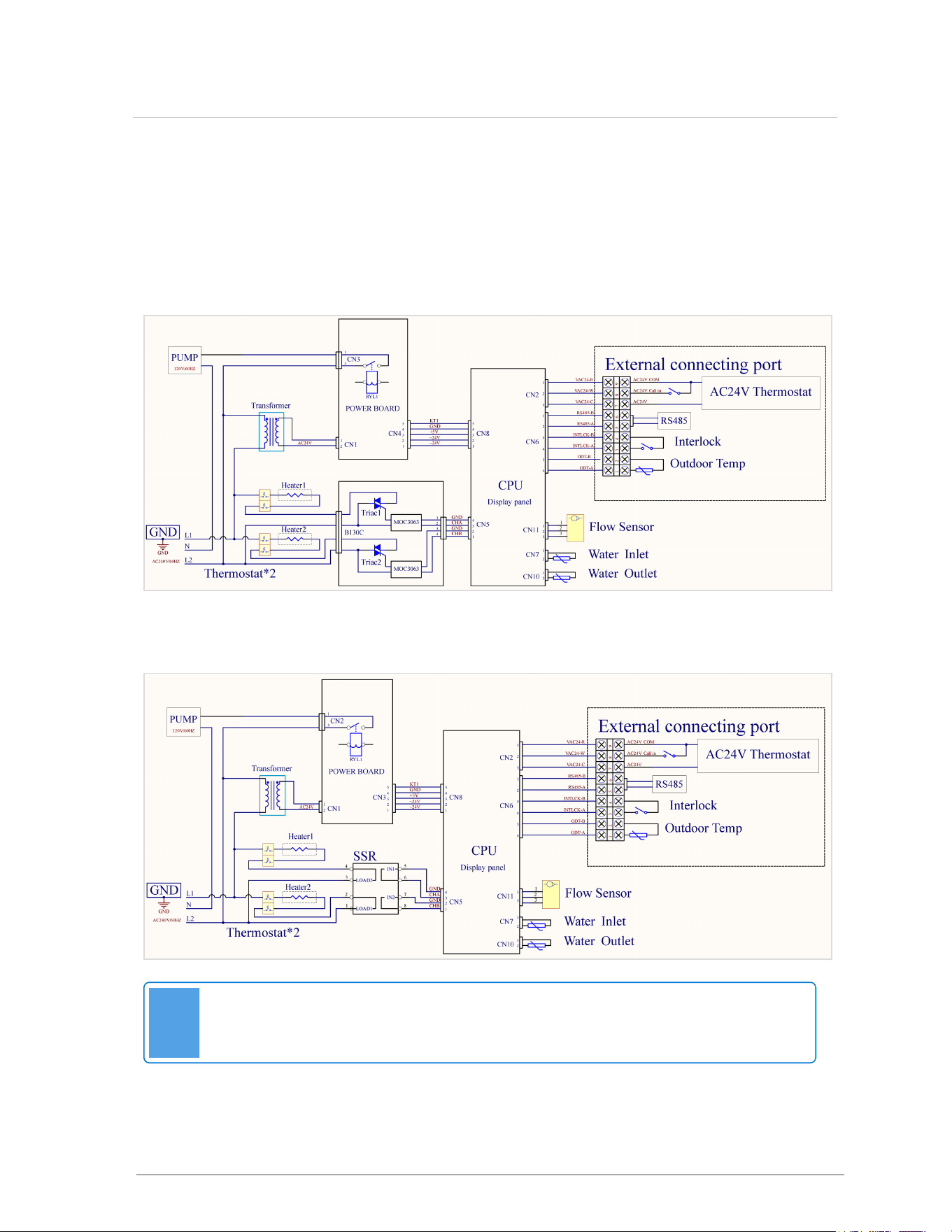
Wiring diagrams
Figure 32 Electric boiler internal wiring diagram-Triac modulation block version
Note
The labels of RS485 A and B are misprinted reversed on some early control boards; in all
cases the true RS485 polarity is as shown above.
Figure 33 Electric boiler internal wiring diagram-Solid State Relay (SSR) modulation block version
55
Appendices
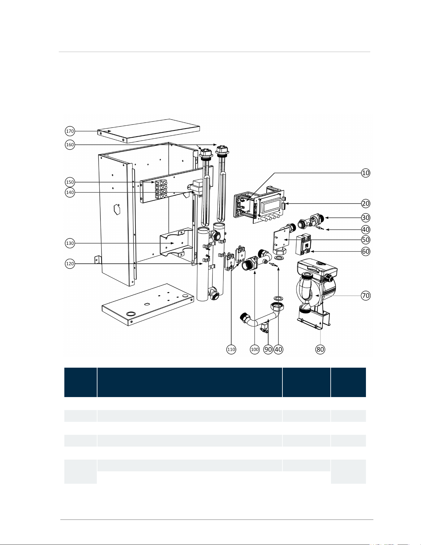
Boiler parts diagram - Electric Boiler
Item ID Description
P-kit
replacement
#
Quantity
10 Power / Pump Relay Board P-1700 1
20 Digital Controller Screen / Terminal Assembly P-1701 1
30 Inlet Water Pipe with Flow Sensor Assembly P-1702 1
40 Water Temperature Sensor
P-1703
2
50 Inlet Pipe / plate assembly P-1704 1
60
Modulation control block (Solid State Relay version) or P-1705
1
Modulation control block (Triac version) P-1706
56
Boiler parts diagram - Electric Boiler

Item ID Description
P-kit
replacement
#
Quantity
70 3-Speed 120V Pump (not including bracket) P-1707
1
80 Pump bracket P-1708 1
90 Drain Pipe Assembly P-1709 1
100 Outlet Pipe Assembly P-1710 1
110 Manual Reset High Limit Switch P-1711 2
120 Heat Exchanger P-1712 1
130 Heat Exchanger Bracket P-1713 1
140 240V Transformer P-1714 1
150 Input Power Terminal Strip P-1715 1
160 Heating Elements
2kW P-1716 2
4kW
P-1717 2
5kW P-1718 2
6kW P-1719 2
170 Cabinet lid P-1720 1
Hardware package (o-rings, screws etc.) P-1721
Wiring harnesses (sold as set; not shown) P-1722
Gasket pack (including inlet filter: sold as set, not shown) P-1723
Optional Parts: Description P-kit replacement #
Outdoor Sensor P-9067
Mesh filter (exterior installation, 3/4") P-913
Air Vent Piping Kit P-195
External Tridicator
P-9014
Boiler Stand P-267
Pressure Relief Valve: 45 psi P-9020
Pressure Relief Valve: 50 psi P-9134
57
Section: Boiler parts diagram - Electric Boiler

Installation & Commissioning Report
Model Number _____________________ Serial Number _______________________________
Date of Installation ________ Address of installation ___________________________________
User contact information _________________________________________________________
Installer Information (Company & Address)___________________________________________
Phone/Fax/E-mail _____________________________________________________________
Circuit Breaker # ____ Labeled? □
Power supply wire gauge _____
□Leak testing completed
□System Cleaned and Flushed (type of cleaner used) ________________________________
□System Filled (type/concentration of any glycol/chemicals used) ______________________
□Air purge completed
□Relief Valve correctly installed and piped Relief valve “try lever” test performed
□Owner advised and instructed in the safe operation and maintenance of the boiler and system.
□Information regarding the appliance and installation received and left with owner
Commissioning has been completed as listed on this report
Installer's Signature __________________________
58
Installation & Commissioning Report

The following message is relevant to users in the USA:
Important
This Boiler is equipped with a feature that saves energy by reducing the boiler water
temperature as the heating load decreases. This feature is equipped with an override
which is provided primarily to permit the use of an external energy management
system that serves the same function.
THIS OVERRIDE MUST NOT BE USED UNLESS AT LEAST ONE OF THE
FOLLOWING CONDITIONS IS TRUE:
• An external energy management system is installed that reduces the boiler water
temperature as the heating load decreases.
• This boiler is not used for any space heating.
• This boiler is part of a modular or multiple boiler system having a total input of
300,000 BTU/hr or greater.
• [not applicable to these boilers] The boiler is equipped with a tankless coil.
59
Section: Boiler parts diagram - Electric Boiler

June 21, 2023 | 120-440E3
©2023