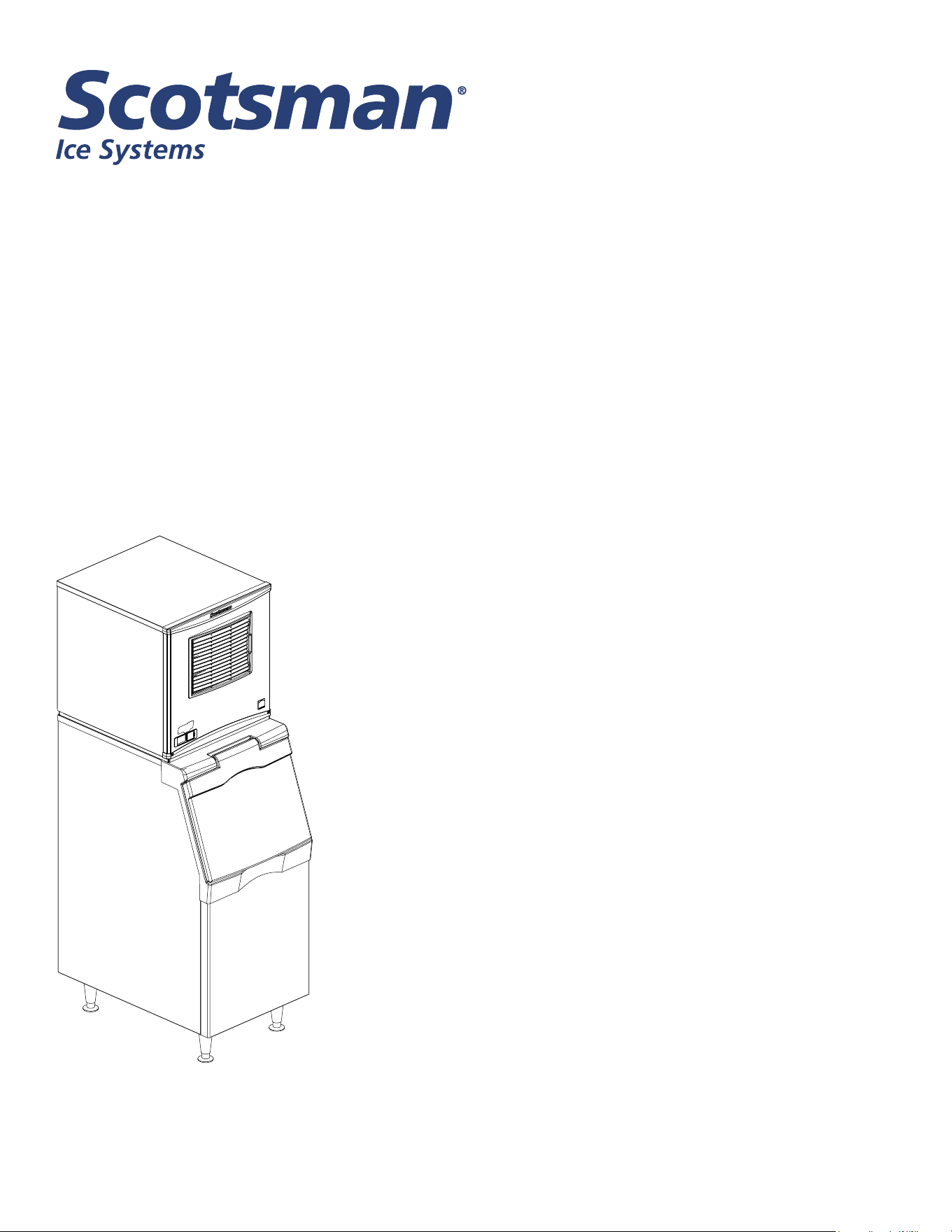
Installation and User’s Manual for
Modular Flake and Nugget Ice Machines
Prodigy Plus A Series Models with R290
NH0422X, NS0422X, FS0522X, NH0622X, NS0622X, FS0822X,
NH0922X, NS0922X, FS1222X, NH1322X, NS1322X, FS1522X
Air Cooled and Water Cooled
NH0422X, NS0422X, FS0522X, NH0622X, NS0622X, FS0822X, NH0922X, NS0922X, FS1222X, NH1322X,
NS1322X, FS1522X
A Series Air and Water User Manual
Important Safety Information. Make sure to read
through fully to avoid severe injury or death.
This ice machine contains FLAMMABLE refrigerant and improper use can result in re or explosion. Do not
use cigarettes, vapes, or cellphones near pipes or cables, as it can be a source of ignition or spark.
This ice machine must not be installed next to equipment with an open ignition source (ie. open flames, an
operating gas appliance, or electric heater). Do not store explosive substances such as aerosol cans with a
ammable propellant in this appliance.
WARNING: Do not use electrical appliances inside the food/ice storage compartments unless they are of the
type recommended by the manufacturer.
WARNING: In order to reduce ammability hazards the installation of this appliance must only be carried out
by a suitably qualied person.
This appliance must be installed according to the safety standard for refrigeration systems presented in ANSI/
ASHRAE 15.
Do not install next to anything that continuously vibrates, avoiding excessive vibrations or pulsations.
Install in a well ventilated environment and ensure ventilation and outlets are not obstructed.
Properly secure electrical wiring and cabling for the machine to minimize wear, vibrations, corrosion, excessive
pressure, sharp edges, or other adverse environmental eects that could cause damage to wiring over time.
Keep re extinguisher nearby in case of emergencies.
WARNING: Do not damage the refrigerating circuit
Use a Scotsman recommended technician certied to repair R290 equipment.
Install ONLY Scotsman factory service parts. Use of non-OEM parts can be dangerous due to the design
changes needed to safely use R290 refrigerant.
WARNING: Cancer and Reproductive Harm. Visit www.P65Warnings.ca.gov for details.
This appliance is not intended for use by persons (including children) with reduced physical, sensory or mental
capabilities, or lack of experience and knowledge, unless they have been given supervision or instruction
concerning the use of the appliance by a person responsible for their safety.
Children should be supervised to ensure that they do not play with the appliance.
Caution: This equipment should only be used on ice bins without electrical components
or bins designed to be used with ammable refrigerants.
Safety Information
R290 Refrigerant is
Flammable.
Flame can cause burns or
property damage
Keep away from sources of re
WARNING
NH0422X, NS0422X, FS0522X, NH0622X, NS0622X, FS0822X, NH0922X, NS0922X, FS1222X, NH1322X,
NS1322X, FS1522X
A Series Air and Water User Manual
Safety Information, continued
WARNING: Do not use means to accelerate the defrosting process or to clean, other than those
recommended by the manufacturer. The appliance shall be stored in a room without continuously operating
ignition sources
Do not pierce or burn.
Be aware that refrigerants may not contain an odor.
All installation, service, maintenance and decommissioning to be carried out by technicians certied to handle
FLAMMABLE REFRIGERANTS.
Install in a well-ventilated environment and ensure ventilation and outlets are not obstructed.
When breaking into the refrigerant circuit to make repairs – or for any other purpose conventional procedures
shall be used. However, for ammable refrigerants it is important that best practice be followed, since
ammability is a consideration. The following procedure shall be adhered to:
a) safely remove refrigerant following local and national regulations;
b) purge the circuit with inert gas;
c) evacuate;
d) purge with inert gas;
e) open the circuit by cutting or brazing.
The refrigerant charge shall be recovered into the correct recovery cylinders if venting is not allowed by local
and national codes. For appliances containing ammable refrigerants, the system shall be purged with oxygen-
free nitrogen to render the appliance safe for ammable refrigerants. This process might need to be repeated
several times. Compressed air or oxygen shall not be used for purging refrigerant systems. For appliances
containing ammable refrigerants, refrigerants purging shall be achieved by breaking the vacuum in the
system with oxygen-free nitrogen and continuing to ll until the working pressure is achieved, then venting
to atmosphere, and nally pulling down to a vacuum. This process shall be repeated until no refrigerant is
within the system. When the nal oxygen-free nitrogen charge is used, the system shall be vented down to
atmospheric pressure to enable work to take place. Ensure that the outlet for the vacuum pump is not close to
any potential ignition sources and that ventilation is available.
Ensure that the leak detection equipment being used is suitable for use with FLAMMABLE REFRIGERANT;
i.e., non-sparking, adequately sealed or intrinsically safe.
NH0422X, NS0422X, FS0522X, NH0622X, NS0622X, FS0822X, NH0922X, NS0922X, FS1222X, NH1322X,
NS1322X, FS1522X
A Series Air and Water User Manual
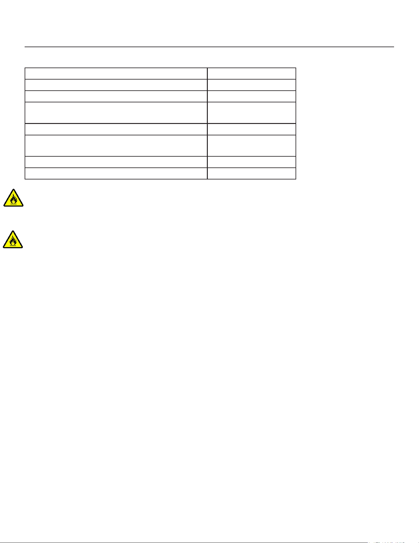
Minimum Installation Area by Model in meters²
Model Number Minimum Area m2
FS0522WX-1, NH0422WX-1, NS0422WX-1 6.1
FS0822WX-1, NS0622WX-1, NH0622WX-1 7.1
FS0522AX-1, NH0422AX-1, NS0422AX-1,
FS1222WX-32, NS0922WX-32, NH0922WX-32
8.1
FS0822AX-1, NS0622AX-1, NH0622AX-1 8.8
FS1222WX-32, NS0922AX-32, NH0922WX-1,
NS0922AX-1, NH0922AX-1
9.4
NS1322WX-32, NH1322WX-32 13.5
NS1322AX-32, NH1322AX-32 16.2
WARNING: This appliance shall be stored in an area where the room size corresponds to the
room area as specied for operation. Please see the table above for the minimum allowed area of
installation.
WARNING: This appliance should be stored in a room without continuously operating open flames
(for example an operating gas appliance) or other potential ignition sources (for example an operating
electric heater, hot surfaces).
Safety Information, continued

April 2025
Page 1
NH0422X, NS0422X, FS0522X, NH0622X, NS0622X, FS0822X, NH0922X, NS0922X, FS1222X, NH1322X,
NS1322X, FS1522X
A Series Air and Water User Manual
Introduction
This ice machine is the result of years of experience
with aked and Scotsman Nugget Ice® ice machines.
The latest in electronics has been coupled with the
time tested Scotsman aked ice system to provide
reliable ice making and the features needed by
customers. The features include easily accessible
air lters, simple conductivity water level sensing,
evaporator clearing at shut down, photo-eye sensing
bin control and the ability to add options.
Contents
Installation: ..................................................................... 2
Location: ....................................................................... 3
NH0422X, NS0422X, FS0522X, NH0622X, NS0622X, F0822X Cabinet Layout ................ 4
NH0922X, NS0922X, FS1222X, NH1322X, NS1322X, FS1522X Cabinet Layout ............... 5
Unpacking & Install Prep ........................................................... 6
Water - Air or Water Cooled ......................................................... 7
Electrical - All Models ............................................................. 8
Electrical - All Models Continued ..................................................... 9
Water .......................................................................... 10
Final Check List .................................................................. 11
Initial Start Up and Maintenance ..................................................... 12
Maintenance: Scale Removal and Sanitation ........................................... 13
Maintenance: Scale Removal and Sanitation Continued .................................. 14
Options ........................................................................ 15
What to Do Before Calling for Service ................................................. 16
Decommissioning ................................................................ 17
NH0422X, NS0422X, FS0522X, NH0622X, NS0622X, FS0822X, NH0922X, NS0922X, FS1222X, NH1322X,
NS1322X, FS1522X
A Series Air and Water User Manual
April 2025
Page 2
Installation:
This machine is designed to be used indoors, in a
controlled environment. Operation outside the limits
listed here will void the warranty.
Air temperature limits
Minimum Maximum
Ice maker 50
o
F. 100
o
F.
Remote
condenser
-20
o
F. 120
o
F.
Water temperature limits
Minimum Maximum
All models 40
o
F. 100
o
F.
Water pressure limits (potable)
Maximum Minimum
All models 20 psi 80 psi
Water pressure limit to water cooled condenser is 150
PSI
Voltage limits
Minimum Maximum
115 volt 104 126
208-230 60 Hz 198 253
Minimum conductivity (RO water)
• 10 microSiemens / CM
Water Quality (ice making circuit)
• Potable, that meets federal and state stands for
consumption.
The quality of the water supplied to the ice machine
will have an impact on the time between cleanings
and ultimately on the life of the product. Water can
contain impurities either in suspension or in solution.
Suspended solids can be ltered out. In solution
or dissolved solids cannot be ltered, they must be
diluted or treated. Water lters are recommended
to remove suspended solids. Some lters have
treatment in them for dissolved solids.
Scale inhibitors are not recommended for use with the
Nugget ice machines. Scale inhibitors will make the
ice softer and melt faster. This can also can lead to
ice dispensing issues if the ice is being dispensed via
beverage dispenser.
Check with a water treatment service for a
recommendation.
RO water. This machine can be supplied with Reverse
Osmosis water, but the water conductivity must be no
less than 10 microSiemens/cm.
Potential for Airborne Contamination
Installing an ice machine near a source of yeast
or similar material can result in the need for more
frequent sanitation cleanings due to the tendency of
these materials to contaminate the machine.
Most water lters remove chlorine from the water
supply to the machine which contributes to this
situation. Testing has shown that using a lter that
does not remove chlorine, such as the Scotsman
Aqua Patrol, will greatly improve this situation.
Warranty Information
The warranty statement for this product is provided
separately from this manual. Refer to it for applicable
coverage. In general warranty covers defects
in material or workmanship. It does not cover
maintenance, corrections to installations, or situations
when the machine is operated in circumstances that
exceed the limitations printed above.
This is a commercial model, if installed in a residence
some commercial service companies may not be able
to service it on site.
Fill out the Warranty Registration by using the
attached warranty and mailing it in, or scan the QR
code to be taken to the Scotsman warranty website:
April 2025
Page 3
NH0422X, NS0422X, FS0522X, NH0622X, NS0622X, FS0822X, NH0922X, NS0922X, FS1222X, NH1322X,
NS1322X, FS1522X
A Series Air and Water User Manual
Location:
While the machine will operate satisfactorily within the
listed air and water temperature limits, it will produce
more ice when those temperatures are nearer the
lower limits. Avoid locations that are hot, dusty,
greasy or conned. Air cooled models need plenty
of room air to vent. Air cooled models must have at
least six inches of space at the back and sides for
air discharge; however, more space will allow better
performance. All models must be open in the front
and have at least 12 inches of space at the back. If an
ignition source is present in the proposed installation
area, 12 inches of space in the back is needed and
39.4 inches of space for the sides are needed to
maintain a safe distance from the nearest ignition
source. Ensure that front and sides of the machine
are accessible.
Airow
Air ows into the front of the cabinet and out the back.
The air lters are on the outside of the front panel and
are easily removed for cleaning.
Options
Ice is made until it lls the bin enough to block an
infrared light beam inside the base of the machine. A
eld installed kit is available to adjust the maintained
ice level lower. The kit number is KVS.
The standard controller has excellent diagnostic
capabilities and communicates to the user through the
AutoAlert light panel, seen through the front panel.
Field installed kits are available that can log data and
provide additional information when the front panel is
removed. The kit numbers are KSBU and KSB-NU.
See page 21.
Bin compatibility
All models have the same footprint: 22 inches wide
by 24 inches deep. Conrm available space when
replacing a prior model.
Bin & adapter list:
• B322S – no adapter needed
• B330P or B530P or B530S – Use KBT27
• B842S – KBT39
• B948S – KBT38 for single unit
• B948S – KBT38-2X for two units side by side
• BH1100, BH1300 and BH1600 upright bins include
ller panels to accommodate a single 22 inch wide
ice machine. No adapter is needed.
Dispenser compatibility
Only nugget ice models may be used with ice
dispensers. Flaked ice is not dispensable.
• IOD150 – use KBT80 and KDIL-PN-150, includes
KVS, KNUGAGT, and R629088514
• IOD200 – use KBT84 and KNUGDIV and KVS
• IOD250 – use KBT84 and KNUGDIV and KVS
See sales literature for other brand model ice and
beverage dispenser applications.
Other Bins & Applications:
Note the drop zone and ultrasonic sensor locations in
the illustrations on the next pages.
Scotsman ice systems are designed and
manufactured with the highest regard for safety and
performance. They meet or exceed UL60335-2-89.
Scotsman assumes no liability of responsibility of
any kind for products manufactured by Scotsman
that have been altered in any way, including the use
of any part and/or other components not specically
approved by Scotsman.
Scotsman reserves the right to make design changes
and/or improvements at any time. Specications and
design are subject to change without notice.
Airow
NH0422X, NS0422X, FS0522X, NH0622X, NS0622X, FS0822X, NH0922X, NS0922X, FS1222X, NH1322X,
NS1322X, FS1522X
A Series Air and Water User Manual
April 2025
Page 4
NH0422X, NS0422X, FS0522X, NH0622X, NS0622X, F0822X Cabinet Layout
ICE DROP
OPENING
WATER COOLED
BACK VIEW
AIR COOLED
BACK VIEW
LEFT SIDE VIEW
FRONT VIEW
57.7
22.70
58.4
23.00
55.9
22.00
LOUVER AND
REMOVABLE FILTER
A/C UNITS ONLY
61
24.00
2.3
.90
4
1.59
5.5
2.17
4.7
1.85
23.1
9.1
37.2
14.65
3/4" FPT
DRAIN
.88 DIA.
ELECTRICAL
ACCESS
3/8" FLARE
MACHINE
WATER
INLET
61
24.00
REF.
41.9
16.50
31.8
12.50
55.9
22.00 REF.
10.9
4.30
16.5
6.48
7.1
2.81
7.4
2.92
PLAN VIEW
23.1
9.1
4
1.59
5.5
2.17
4.7
1.85
37.1
14.60
8.6
3.38
39.2
15.45
44.6
17.55
49.1
19.31
3/8" FPT
CONDENSER
WATER
INLET
.88 DIA.
ELECTRICAL
CONNECTION
3/8" FLARE
MACHINE
WATER
INLET
3/4" FPT
DRAIN
1/2" FPT
CONDENSER
DRAIN
Note: Bin Top
Cut-outs for
drop zone
should include
ultrasonic
sensor location
April 2025
Page 5
NH0422X, NS0422X, FS0522X, NH0622X, NS0622X, FS0822X, NH0922X, NS0922X, FS1222X, NH1322X,
NS1322X, FS1522X
A Series Air and Water User Manual
NH0922X, NS0922X, FS1222X, NH1322X, NS1322X, FS1522X Cabinet Layout
ICE DROP
OPENING
PLAN VIEW
WATER COOLED
BACK VIEW
AIR COOLED
BACK VIEW
LEFT SIDE VIEW
FRONT VIEW
55.9
22.00
68.6
27.00
57.7
22.70
LOUVER AND
REMOVABLE FILTER
A/C UNITS ONLY
61
24.00
30.7
12.10
4
1.59
4.7
1.85
47.4
18.65
3/4" FPT
DRAIN
3/8" FLARE
MACHINE
WATER
INLET
.88 DIA.
ELECTRICAL
ACCESS
61
24.00
REF.
55.9
22.00
REF.
31.8
12.50
10.9
4.30
16.5
6.48
7.4
2.92
7.1
2.81
ULTRA SONIC
BIN LEVEL
SENSOR
OPTIONAL
4
1.59
48.3
19.00
44.6
17.56
5.5
2.17
30.7
12.10
12.6
4.95
39.2
15.45
4.7
1.85
47.2
18.60
3/8" FPT
CONDENSER
WATER
INLET
1/2" FPT
CONDENSER
DRAIN
3/8" FLARE
MACHINE
WATER
INLET
.88 DIA.
ELECTRICAL
CONNECTION
3/4" FPT
DRAIN
Note: Bin Top Cut-outs
for drop zone should
include ultrasonic
sensor location
NH0422X, NS0422X, FS0522X, NH0622X, NS0622X, FS0822X, NH0922X, NS0922X, FS1222X, NH1322X,
NS1322X, FS1522X
A Series Air and Water User Manual
April 2025
Page 6
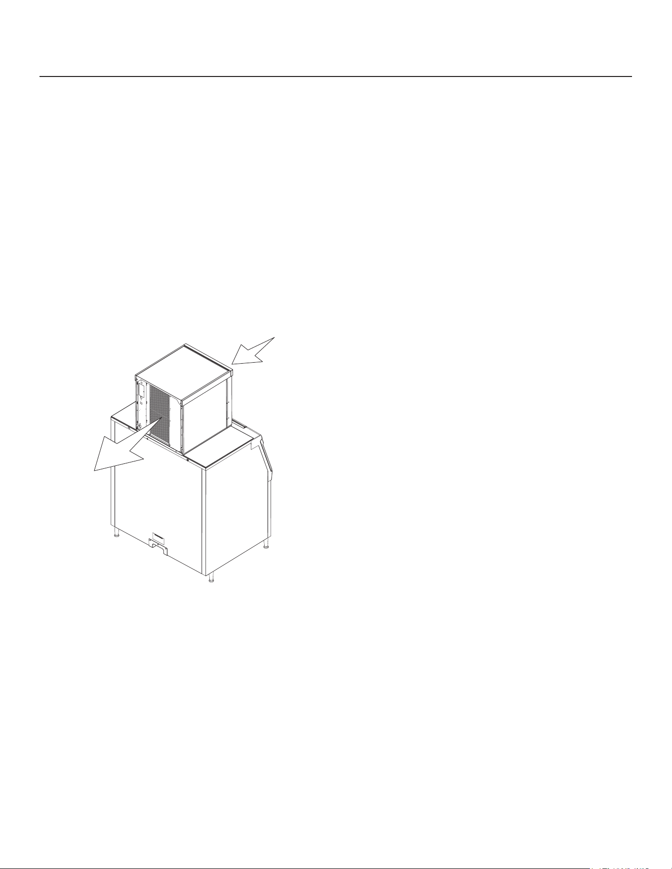
Unpacking & Install Prep
Remove the carton from the skid. Check for hidden
freight damage, notify the carrier immediately if any is
found. Retain the carton for the carrier’s inspection.
The machine is not bolted to the skid. If strapped
remove the strap.
Place on Bin or Dispenser
If reusing an existing bin, be sure that the bin is
in good shape and that the gasket tape on the
top is not torn up. Water leaks, not covered by
warranty, could result from a poor sealing surface. If
installing a remote or a remote low side, a new bin
is recommended due to the high cost to the user of
replacing an old bin when a remote system is on top.
Install the correct adapter, following the directions
supplied with that adapter.
Hoist the machine onto the adapter.
Note: The machine is heavy! Use of a mechanical lift
is recommended.
Position the machine on the bin or adapter. Secure
with straps from the hardware bag packed with the
machine, or those supplied with the adapter.
Remove any plastic covering the stainless steel
panels.
Remove any packaging, such as tape or foam blocks,
that may be near the gear reducer or ice chute.
Level the bin and ice machine front to back and left to
right by using the bin leg levelers.
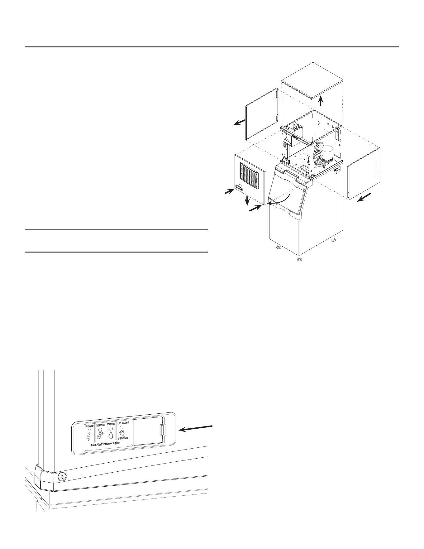
Panel Removal
1. Locate and loosen the two screws at the bottom of
the front panel.
2. Pull the front panel out at the bottom until it clears.
3. Lower the front panel down and o the machine.
4. Remove two screws at the front of the top panel.
Lift up the front of the top panel, push the top panel
back an inch, then lift to remove.
5. Locate and loosen the screw holding each side
panel to the base. Left side panel also has a screw
holding it to the control box.
6. Pull the side panel forward to release it from the
back panel.
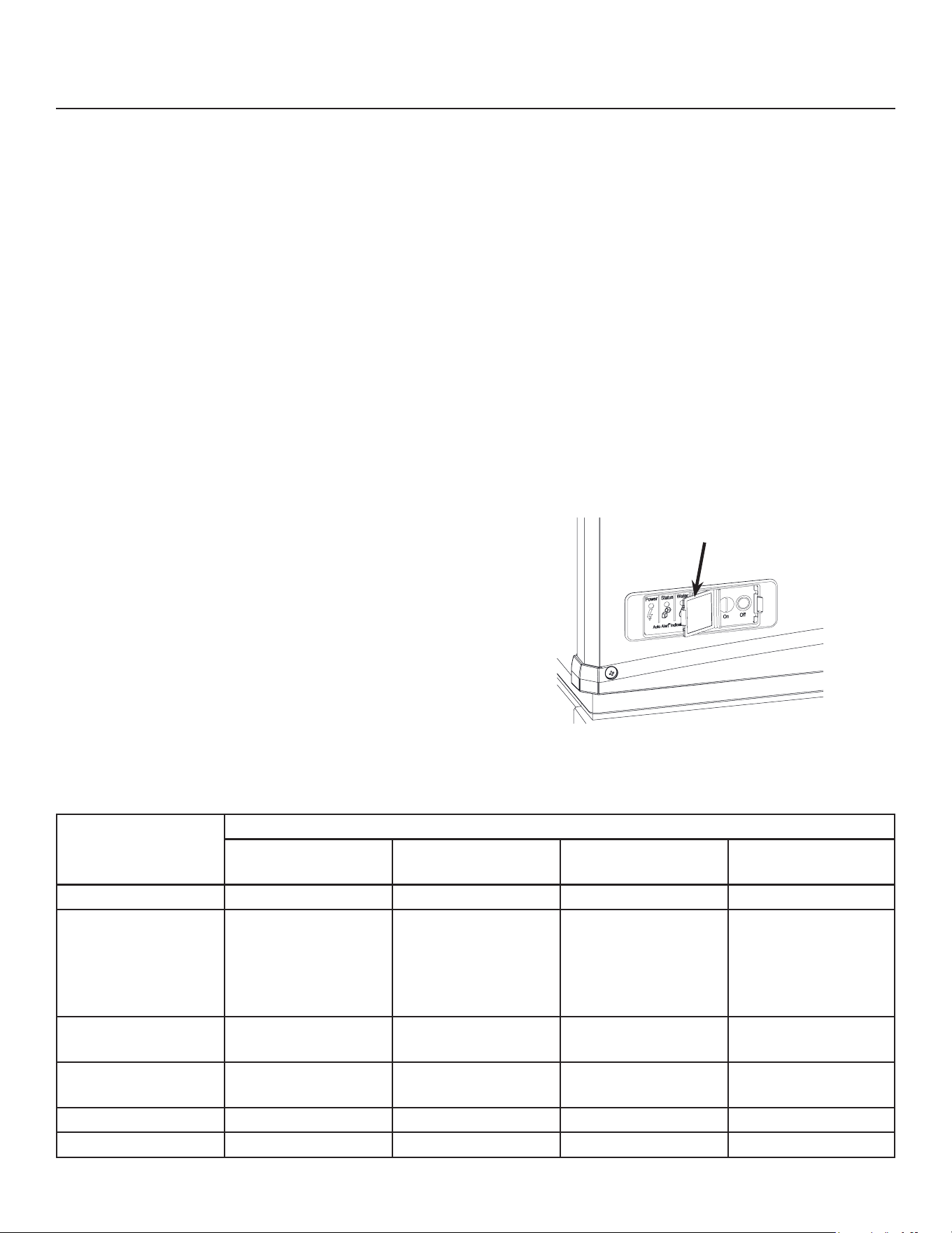
Control Panel Door
The door can be moved to allow access to the on and
o switches.
April 2025
Page 7
NH0422X, NS0422X, FS0522X, NH0622X, NS0622X, FS0822X, NH0922X, NS0922X, FS1222X, NH1322X,
NS1322X, FS1522X
A Series Air and Water User Manual
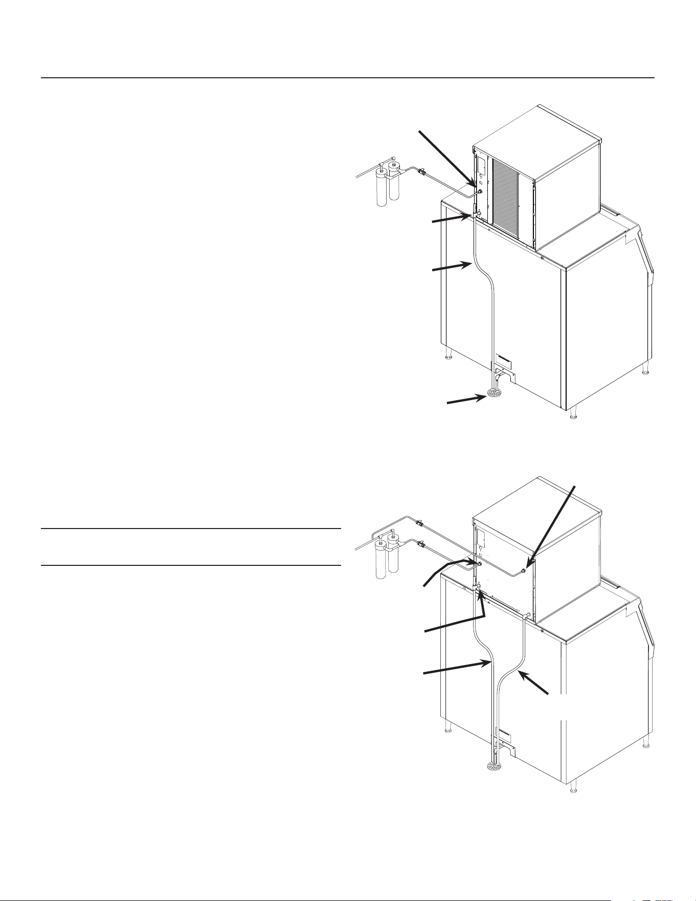
Water - Air or Water Cooled
The water supply for ice making must be cold, potable
water. There is a single 3/8” male are potable water
connection on the back panel. Water cooled models
also have a 3/8” FPT inlet connection for the water
cooled condenser. Chilled water can also be used for
this connection.
Backow
The design of the oat valve and reservoir prevents
potable water backow by means of a 1" air gap
between the reservoir's maximum water level and the
oat valve water inlet orice.
Drain
There is one 3/4” FPT condensate drain tting at the
back of the cabinet. Water cooled models also have
a 1/2” FPT discharge drain connection on the back
panel.
Attach Tubing
Connect the potable water supply to the potable water
tting, 3/8” OD copper tubing or the equivalent is
recommended.
Water ltration is recommended. If there is an existing
lter, change the cartridge.
Connect the water cooled water supply to the
condenser inlet.
Note: Do NOT lter water to the water cooled
condenser circuit.
Drains - use rigid tubing: Connect the drain tube to the
condensate drain tting. Vent the drain.
Connect the water cooled condenser drain tube to the
condenser outlet. Do not vent this drain.
Do not Tee ice machine drains into the drain tube
from the ice storage bin or dispenser. Back ups
could contaminate and / or melt the ice in the bin or
dispenser. Be sure to vent the bin drain.
Follow all local and national codes for tubing, traps
and air gaps.
Water Inlet
Connection
Drain
Connection
Condensate
Drain Tube
Building Drain
Water Inlet
Connection
Drain
Connection
Condensate
Drain Tube
Condenser Inlet
Connection
Condenser
Drain Tube
Air Cooled Plumbing
Water Cooled Plumbing
NH0422X, NS0422X, FS0522X, NH0622X, NS0622X, FS0822X, NH0922X, NS0922X, FS1222X, NH1322X,
NS1322X, FS1522X
A Series Air and Water User Manual
April 2025
Page 8
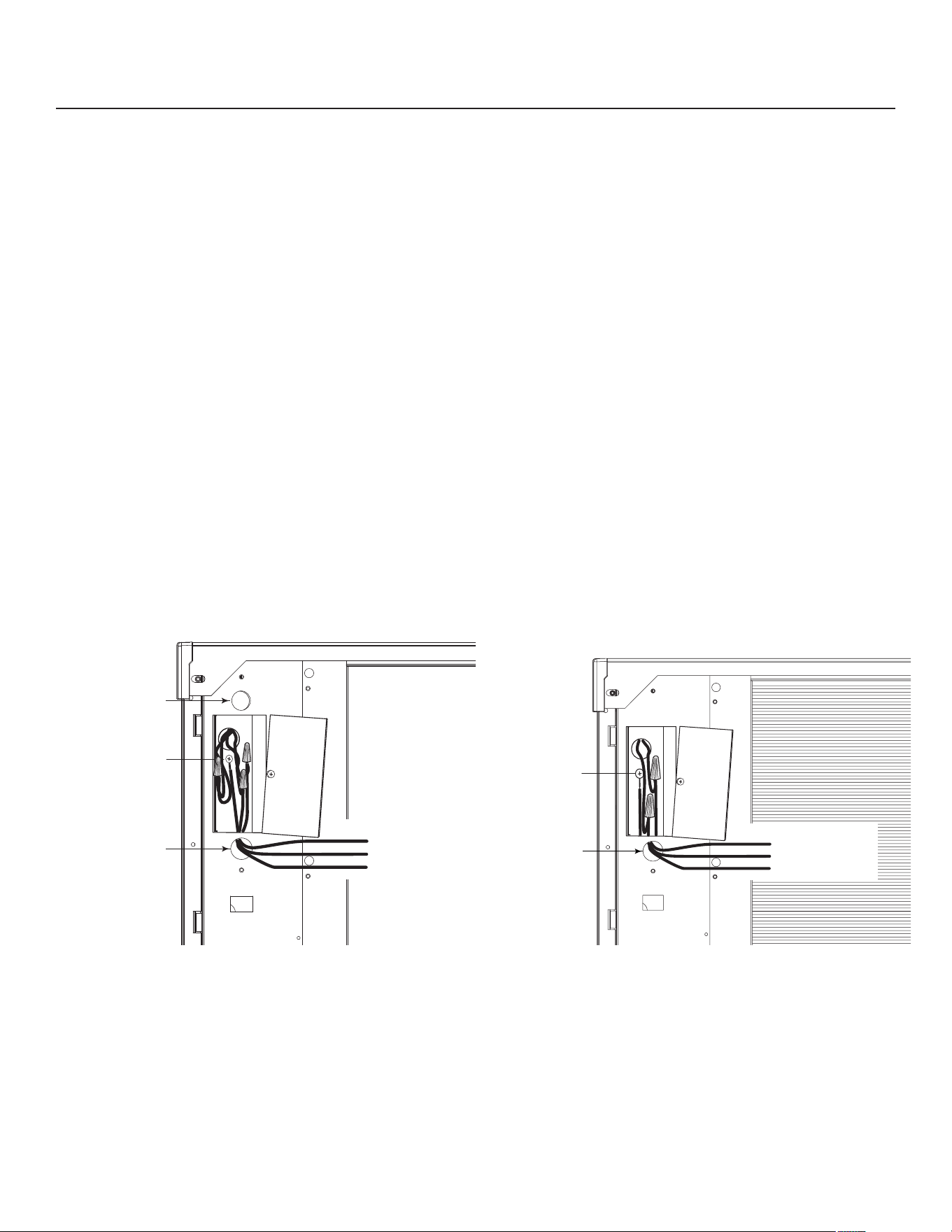
Electrical - All Models
The machine does not include a power cord, one
must be eld supplied or the machine hard wired to
the electrical power supply.
The junction box for the power cord is on the back
panel. See the next page.
Refer to the dataplate on the machine for minimum
circuit ampacity and determine the proper wire size
for the application. The dataplate (on the back of the
cabinet) also includes the maximum fuse size.
Connect electrical power to wires inside the junction
box in the back of the cabinet. Use a strain relief and
connect a ground wire to the ground screw.
Do not use an extension cord. Follow all local and
national codes.
This unit must be on a separate power supply. Check
the dataplate for the voltage, ampacity and maximum
fuse size and per the dataplate use fuses or HACR
circuit breakers.
This ice machine should be installed on a dedicated
circuit with a properly sized HACR-rated breaker
or fuse. No other devices or appliances should be
connected to the same circuit with the ice machine.
Installing a unit on a shared circuit can cause product
malfunctions or damage to the unit. The proper circuit
size can be found on the unit data tag listed as “MAX
FUSE OR HACR TYPE CIRCUIT BREAKER”. Never
allow the fuse size to exceed the maximum fuse size
listed on the data tag.
The use of a ground fault circuit interrupter (GFCI)
or arc-fault circuit interrupter (ARCI) can lead to
nuisance trips and is not recommended for use on
most appliances including our equipment.
If local codes or other specications require the use
of ground fault circuit interrupters, a properly rated
HACR GFCI or ARCI circuit breaker should be used.
An outlet type GFCI or ARCI is not recommended for
ice machines and other refrigeration equipment due to
more frequent nuisance trips of the GFCI or ARCI.
Always check with your local electrical inspector about
the specic code requirements in your area for GFCI
or ARCI breakers and GFCI or ARCI receptacles.
The junction box is on the back panel.
Ground
Wire
Connection
Black
White
Ground
Power
Supply
Wires
Install
Strain
Relief
Install
Strain
Relief
Junction
Box
Cover
Ground
Wire
Connection
Black
White
Ground
Power
Supply
Wires
Install
Strain
Relief
Junction
Box
Cover
April 2025
Page 9
NH0422X, NS0422X, FS0522X, NH0622X, NS0622X, FS0822X, NH0922X, NS0922X, FS1222X, NH1322X,
NS1322X, FS1522X
A Series Air and Water User Manual
Electrical - All Models Continued
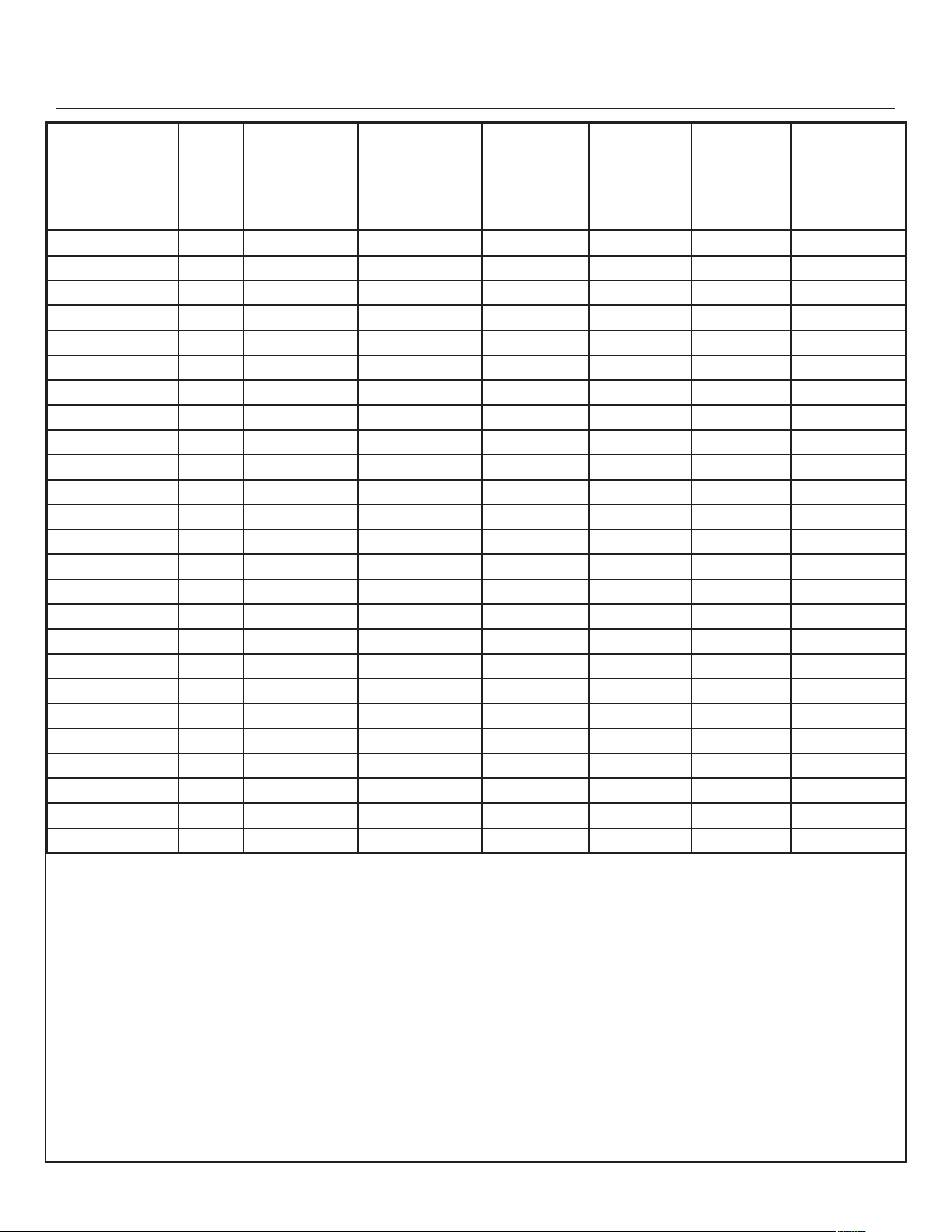
Model Series Dimensions
w” x d” x h”
Voltage
Volts/Hz/
Phase
Condenser
Type
Refrigerant
type
Min Circuit
Ampacity
Max Fuse
Size or
HACR
Type Circuit
Breaker
NH0422AX-1 A 22 x 24 x 23 115/60/1 Air R290 11.1 15
NS0422AX-1 A 22 x 24 x 23 115/60/1 Air R290 11.1 15
FS0522AX-1 A 22 x 24 x 23 115/60/1 Air R290 11.1 15
NH0422WX-1 A 22 x 24 x 23 115/60/1 Water R290 10.3 15
NS0422WX-1 A 22 x 24 x 23 115/60/1 Water R290 10.3 15
FS0522WX-1 A 22 x 24 x 23 115/60/1 Water R290 10.3 15
NH0622AX-1 A 22 x 24 x 23 115/60/1 Air R290 14.8 20
NS0622AX-1 A 22 x 24 x 23 115/60/1 Air R290 14.8 20
FS0822AX-1 A 22 x 24 x 23 115/60/1 Air R290 14.8 20
NH0622WX-1 A 22 x 24 x 23 115/60/1 Water R290 13.2 15
NS0622WX-1 A 22 x 24 x 23 115/60/1 Water R290 13.2 15
FS0822WX-1 A 22 x 24 x 23 115/60/1 Water R290 13.2 15
NH0922AX-32 A 22 x 24 x 27 208-230/60/1 Air R290 10.6 15
NS0922AX-32 A 22 x 24 x 27 208-230/60/1 Air R290 10.6 15
FS1222AX-32 A 22 x 24 x 27 208-230/60/1 Air R290 10.6 15
NH0922WX-32 A 22 x 24 x 27 208-230/60/1 Water R290 9.5 15
NS0922WX-32 A 22 x 24 x 27 208-230/60/1 Water R290 9.5 15
FS1222WX-32 A 22 x 24 x 27 208-230/60/1 Water R290 9.5 15
NH0922AX-1 A 22 x 24 x 27 115/60/1 Air R290 24.0 30
NS0922WX-1 A 22 x 24 x 27 115/60/1 Water R290 25.0 30
NH1322AX-32 A 22 x 24 x 27 208-230/60/1 Air R290 17.8 20
NH1322WX-32 A 22 x 24 x 27 208-230/60/1 Water R290 16.6 20
NS1322AX-32 A 22 x 24 x 27 208-230/60/1 Air R290 17.8 20
NS1322WX-32 A 22 x 24 x 27 208-230/60/1 Water R290 16.6 20
FS1522AX-32 A 22 x 24 x 27 208-230/60/1 Air R290 17.8 20
NH0422X, NS0422X, FS0522X, NH0622X, NS0622X, FS0822X, NH0922X, NS0922X, FS1222X, NH1322X,
NS1322X, FS1522X
A Series Air and Water User Manual
April 2025
Page 10
Water
The water supply for ice making must be cold, potable
water. There is a single 3/8” male are potable water
connection on the back panel.
Backow
The design of the oat valve and reservoir prevents
potable water backow by means of a 1" air gap
between the reservoir's maximum water level and the
oat valve water inlet orice.
Drain
There is one 3/4” FPT condensate drain tting at the
back of the cabinet.
Attach Tubing
1. Connect the potable water supply to the potable
water tting, 3/8” OD copper tubing or the
equivalent is recommended.
2. Change the cartridge on the existing water lter (if
any present).
3. Connect the drain tube to
the condensate drain tting.
Use rigid tubing.
4. Vent the drain tubing
between the ice machine
and the building drain.
Do not Tee ice machine drains into the drain tube
from the ice storage bin or dispenser. Back ups
could contaminate and / or melt the ice in the bin or
dispenser. Be sure to vent the bin drain.
Follow all local and national codes for tubing, traps
and air gaps.
To Remote Condenser
Potable Water
Connection
Drain Vent
Condensate Drain
April 2025
Page 11
NH0422X, NS0422X, FS0522X, NH0622X, NS0622X, FS0822X, NH0922X, NS0922X, FS1222X, NH1322X,
NS1322X, FS1522X
A Series Air and Water User Manual
Power
Status
No Water
Time to Clean
On
O
Final Check List
After connections:
1. Wash out the bin. If desired, the interior of the bin
could be sanitized.
2. Locate the ice scoop (if supplied) and have it
available for use when needed.
Final Check List:
1. Is the unit located indoors in a controlled
environment?
2. Is the unit located where it can receive adequate
cooling air?
3. Has the correct electrical power been supplied to
the machine?
4. Have all the water supply connections been
made?
5. Have all the drain connections been made?
6. Has the unit been leveled?
7. Have all unpacking materials and tape been
removed?
8. Has the protective covering on the exterior panels
been removed?
9. Is the water pressure adequate?
10. Have the drain connections been checked for
leaks?
11. Has the bin interior been wiped clean or sanitized?
12. Have any water lter cartridges been replaced?
13. Have all required kits and adapters been properly
installed?
Control and Machine Operation
Once started, the ice machine will automatically make
ice until the bin or dispenser is full of ice. When ice
level drops, the ice machine will resume making ice.
___________________________________________
ATTENTION! - During startup, you may observe
frost forming on the compressor. This is normal
and is due to the high eciency refrigerant used
in the machine. The frost should dissipate a few
minutes after startup. Please contact Scotsman
tech support if it does not.
___________________________________________
Caution: Do not place anything on top of the ice
machine, including the ice scoop. Debris and moisture
from objects on top of the machine can work their way
into the cabinet and cause serious damage. Damage
caused by foreign material is not covered by warranty.
There are four indicator lights at the front of the
machine that provide information on the condition
of the machine: Power, Status, Water, De-scale &
Sanitize.
Note: If the De-Scale & Sanitize light is ON, following
the cleaning process will clear the light for another
cleaning time internal.
Two button switches are at the front – On and O. To
switch the machine OFF, push and release the O
button. The machine will shut o at the end of the next
cycle. To switch the machine ON, push and release
the On button. The machine will go through a start up
process and then resume ice making.
Lower Light and Switch Panel
This user accessible panel provides important
operational information and duplicates the lights and
switches on the controller. It also allows access to the
On and O buttons that operate the ice machine.
Sometimes access to the switches should be limited
to prevent unauthorized operation. For that purpose a
xed panel is shipped in the hardware package. The
xed panel cannot be opened.
To install the xed panel:
1. Remove the front panel and remove the bezel.
2. Spread the bezel frame open and remove original
door, insert xed panel into bezel. Be sure it is in
the closed position.
3. Return bezel to panel and install panel on unit.

NH0422X, NS0422X, FS0522X, NH0622X, NS0622X, FS0822X, NH0922X, NS0922X, FS1222X, NH1322X,
NS1322X, FS1522X
A Series Air and Water User Manual
April 2025
Page 12
Initial Start Up and Maintenance
1. Turn the water supply on.
2. Conrm voltage and switch on electrical power.
3. Push and release the On button. The machine will
start in about two minutes.
4. Soon after starting, air cooled models will begin
to blow warm air out the back of the cabinet and
water cooled models will drain warm water from
the condenser drain tube. Remote models will be
discharging warm air from the remote condenser.
After about 5 minutes, ice will begin to drop into
the bin or dispenser.
5. Check the machine for unusual rattles. Tighten
any loose screws, be sure no wires are rubbing
moving parts. Check for tubes that rub. Remote
models check brazed connections for leaks,
retighten as needed.
6. Scan the QR code found behind the front panel
door and complete the warranty registration
online or ll out and mail the included warranty
registration card
7. Notify the user of the maintenance requirements
and whom to call for service.
Maintenance
This ice machine needs ve types of maintenance:
• Air cooled and remote models need their air lters
or condenser coils cleaned regularly.
• All models need scale removed from the water
system.
• All models require regular sanitization.
• All models require sensor cleaning.
• All models require a top bearing check.
Maintenance Frequency:
Air lters: At least twice a year, but in dusty or greasy
air, monthly.
Scale removal. At least twice a year, in some water
conditions it might be every 3 months. The yellow De-
Scale & Sanitize light will switch on after a set period
of time as a reminder. The default time period is 6
months of power up time.
Sanitizing: Every time the scale is removed or as
often as needed to maintain a sanitary unit.
Sensor Cleaning: Every time the scale is removed.
Top bearing check: At least twice a year or every
time the scale is removed. During the course of
normal operation, some material buildup on top of the
bearing is normal and should be wiped away during
maintenance.
Maintenance: Air lters
1. Pull air lter(s) from panel.
2. Wash the dust and grease o the lter(s).
3. Return it(them) to their original position(s).
Do not operate the machine without the lter in place
except during cleaning.
Maintenance: Air cooled condenser
If the machine has been operated without a lter the
air cooled condenser ns will need to be cleaned.
They are located under the fan blades. The services
of a refrigeration technician will be required to clean
the condenser.
Maintenance: Exterior Panels
The front and side panels are durable metal.
Fingerprints, dust and grease will require cleaning
with a good quality stainless steel cleaner
Note: If using a sanitizer or a cleaner that contains
chlorine on the panels, after use be sure to wash the
panels with clean water to remove chlorine residue.
Maintenance: Water lters
If the machine has been connected to water lters,
check the cartridges for the date they were replaced
or for the pressure on the gauge. Change cartridges
if they’ve been installed more than 6 months or if the
pressure drops too much during ice making.
April 2025
Page 13
NH0422X, NS0422X, FS0522X, NH0622X, NS0622X, FS0822X, NH0922X, NS0922X, FS1222X, NH1322X,
NS1322X, FS1522X
A Series Air and Water User Manual
Maintenance: Scale Removal and Sanitation
Note: Following this procedure will reset the de-scale
and sanitize light.
Preparing to Clean:
1. Remove both the front and right panels.
2. Push and release the OFF button.
3. Remove ice from bin or dispenser.
4. Remove the ice chute cover.
5. Remove the water reservoir cover.
6. Turn the water supply to the oat valve o by
turning the knob 1/4 turn CCW.
7. Drain the water reservoir and evaporator into a
bucket using the vent tube. Return the vent tube to
it’s original collar bracket.
8. Using a small cup for precise pouring, add hot
(100-120°F) water into the reservoir until water
comes out of the top of the evaporator at the
extruder, about 1qt (varies slightly by model).
9. Let hot water warm evaporator for 2-5 minutes and
then drain the system (refer to step 7)
10. Loosen the thumb screw and raise the water
reservoir from the “Make Ice” position to the
“Clean” position.
Scale Removal:
11. Prepare a solution of 16oz. Scotsman Clear One
scale remover and 16oz. 95-115 °F. potable water.
12. Using a small cup for precise pouring, add the
scale remover solution into the reservoir until the
solution comes out of top of the evaporator at the
extruder, about 1qt (varies slightly by model).
13. Push and release the Clean button: C is displayed
and the Time to Clean light blinks. The auger
will turn and circulate the scale remover for 30
minutes before shutting o. No ice is made during
the cleaning cycle.
14. Lower the water reservoir back to the “Make Ice”
position. Drain the water reservoir and evaporator
into a bucket using the vent tube.
15. Perform a rinse of the system: turn the water
supply to the oat valve back on and allow the
evaporator to ll. Once full, turn the water supply
at the oat valve o and drain the system using
the vent tube. Return the vent tube to it’s original
collar bracket.
Sanitize:
16. Loosen the thumb screw and raise the water
reservoir from the “Make Ice” position to the
“Clean” position.
17. Prepare a solution of sanitizer. Mix 4 oz. of locally
approved sanitizer and 2.5 gallons of 95-115 °F.
potable water to create a 200 ppm solution.
18. Using a small cup for precise pouring, add the
sanitizer solution into the reservoir until the
solution comes out of top of the evaporator at
the extruder, about 1qt (varies slightly by model).
Reserve any excess sanitizer.
19. Allow the sanitizer to soak while steps 20-24 are
completed, or at least 60 seconds.
Continued on next page:
Ice machine scale remover
contains acids. Acids can
cause burns.
If concentrated cleaner
comes in contact with
skin, ush with water. if
swallowed, do NOT induce
vomiting.
Give large amounts of
water or milk. Call Physician
immediately. Keep out of the
reach of children.
NH0422X, NS0422X, FS0522X, NH0622X, NS0622X, FS0822X, NH0922X, NS0922X, FS1222X, NH1322X,
NS1322X, FS1522X
A Series Air and Water User Manual
April 2025
Page 14
Change De-Scale Notication Interval:
This feature is accessible only from standby
(Status Light O).
1. Press and hold Clean button for 3 seconds.
This starts the Time to Clean Adjustment State and
displays the current time to clean setting.
2. Press the clean button repeatedly to cycle through
the 4 possible settings:
0 (disabled), 4 months, 6 months (default), 1 year
3. Push O to conrm the selection.
Maintenance: Scale Removal and Sanitation Continued
Remove Internal Parts for Cleaning:
20. Remove the ice sweep, upper ice chute, lower
ice chute, and bin eyes for additional cleaning.
The reservoir cover and chute cover were already
removed and should also be cleaned.
21. Prepare a solution of 4oz. Scotsman Clear One
scale remover and 16oz. 95-115 °F. potable water.
Using a nylon brush, scrub each part with scale
remover and rinse, excluding the bin eyes.
22. Using the leftover sanitizing solution and a nylon
brush, scrub each part, excluding the bin eyes.
23. Gently wipe down the bin eyes with scale remover,
rinse, and dry thoroughly (important).
24. Return all parts to their original position.
Note: Eye holders must be mounted properly. They
snap into a centered position and are properly located
when the wires are routed to the back and the left eye
is the one with 2 wires at the connector.
Finish Cleaning Process:
25. Lower the water reservoir back to the “Make Ice”
position. Drain the water reservoir and evaporator
into a bucket using the vent tube.
26. Perform a rinse of the system: turn the water
supply to the oat valve back on and allow the
evaporator to ll. Once full, turn the water supply
at the oat valve o and drain the system using
the vent tube. Return the vent tube to it’s original
collar bracket.
27. Switch the water supply to the ice machine on and
check for leaks as the system lls.
28. Push and release the ON button.
29. Allow the unit to make ice for at least 5 minutes
while washing the inside of the ice storage bin with
sanitizing solution. Discard or melt all ice made
during this step.
30. Return the right and front panels to their original
position and secure with the original screws.
April 2025
Page 15
NH0422X, NS0422X, FS0522X, NH0622X, NS0622X, FS0822X, NH0922X, NS0922X, FS1222X, NH1322X,
NS1322X, FS1522X
A Series Air and Water User Manual
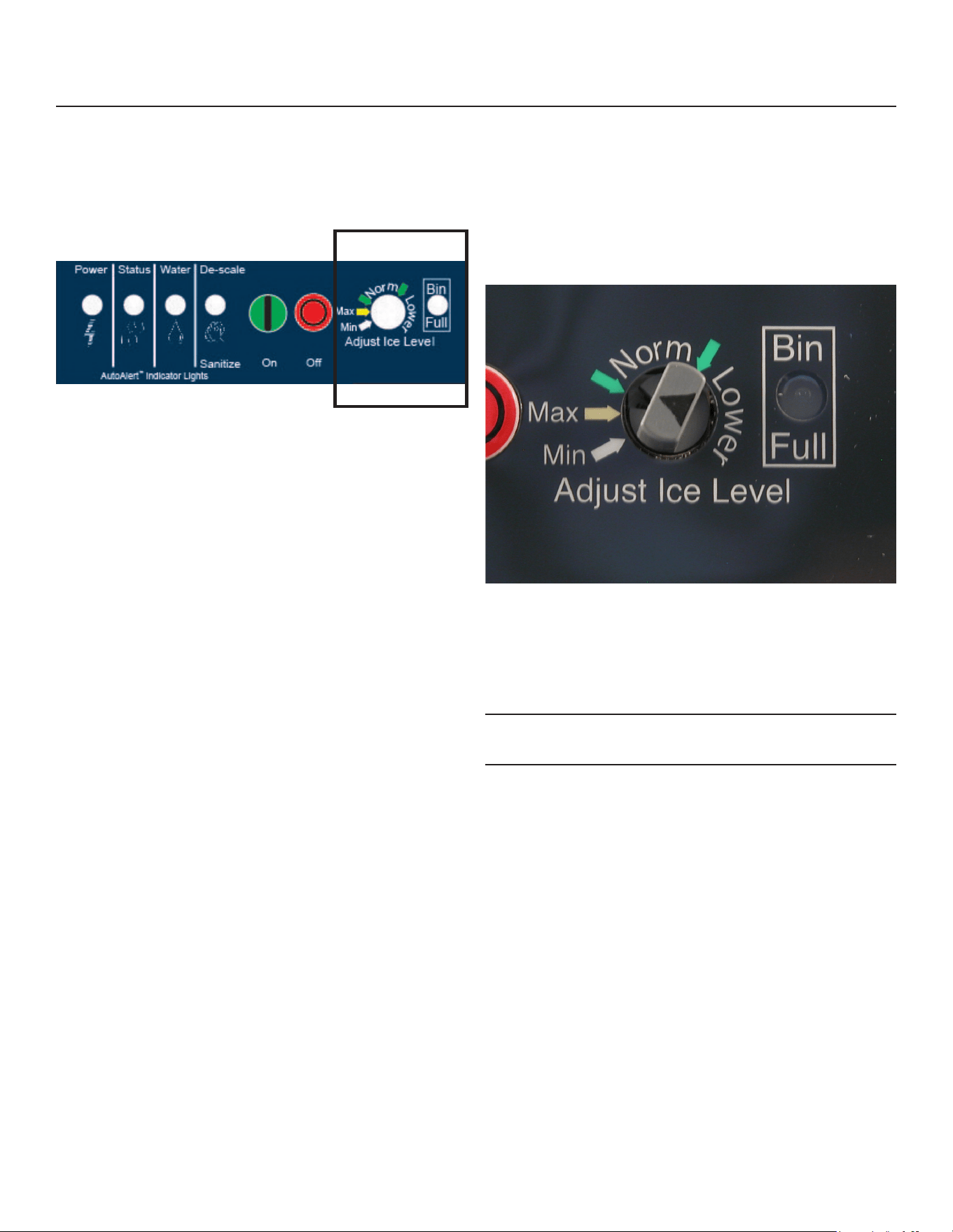
Options
Vari-Smart
Optional adjustable ice level control (KVS). When
this option is present there is an adjustment post and
an additional indicator light to the right of the four
indicator lights mentioned earlier.
The ultrasonic ice level control allows the user to
control the point that the ice machine will stop making
ice before the bin or dispenser is full.
Reasons for this include:
• Seasonal changes in ice used
• Planning to sanitize the bin
• Faster turnover for fresher ice
• Certain dispenser applications where maximum ice
level is not desired
Use of adjustable ice level control
There are several positions the ice level can be set to,
including O or Max (knob and label indicators lined
up), where it lls the bin until the standard bin control
shuts the machine o. See the kit’s instructions for
complete details including special instructions for
dispenser applications.
Rotate the adjustment post to the desired ice level.
The machine will ll up to that level and when it shuts
o the indicator light next to the adjustment post will
be On.
Note: The maximum ll position is when the arrow on
the knob points to the arrow on the label.
NH0422X, NS0422X, FS0522X, NH0622X, NS0622X, FS0822X, NH0922X, NS0922X, FS1222X, NH1322X,
NS1322X, FS1522X
A Series Air and Water User Manual
April 2025
Page 16
What to Do Before Calling for Service
Normal Operation:
Ice
The machine will make either aked or nugget ice,
depending upon the model. The ice will be produced
continuously until the bin is full. It is normal for a few
drops of water to occasionally fall with the ice.
Heat
On remote models most heat is exhausted at the
remote condenser, the ice machine should not
generate signicant heat. Water cooled models
also put most of the heat from ice making into the
discharge water. Air cooled models will generate heat,
and it will be discharged into the room.
Noise
The ice machine will make noise when it is in ice
making mode. The compressor and gear reducer will
produce sound. Air cooled models will add fan noise.
Some ice making noise could also occur. These
noises are all normal for this machine.
Reasons the machine might shut itself o:
• Lack of water.
• Does not make ice
• Auger motor overload
• High discharge pressure.
• Low refrigeration system pressure.
Check the following:
1. Has the water supply to the ice machine or
building been shut o? If yes, the ice machine will
automatically restart within minutes after water begins
to ow to it.
2. Has power been shut o to the ice machine? If yes,
the ice machine will automatically restart when power
is restored.
3. Has someone shut the power o to the remote
condenser while the ice machine still had power? If
yes, the ice machine may need to be manually reset.
To Manually Reset the machine.
• Open the switch door
• Push and release the O button.
• Push and release the On button.
To Shut the Machine O:
Push and hold the O button for 3 seconds or until the
machine stops.
Indicator Lights & Their Meanings
Power Status Water De-Scale &
Sanitize
Steady Green Normal Normal - -
Blinking Green Self Test Failure Switching on or
o. When Smart-
Board used,
machine attention
recommended.
- -
Blinking Red - Diagnostic shut
down
Lack of water -
Yellow - - - Time to descale and
sanitize
Blinking Yellow - - - In Cleaning Mode
Light O No power Switched to O Normal Normal
Open Switch Door

April 2025
Page 17
NH0422X, NS0422X, FS0522X, NH0622X, NS0622X, FS0822X, NH0922X, NS0922X, FS1222X, NH1322X,
NS1322X, FS1522X
A Series Air and Water User Manual
Decommissioning
Only qualied technicians familiar with R290
refrigerant should decommission a machine, as
special tools and containers are required for the
removal, transportation, and disposal of this highly
ammable substance.
Work shall be undertaken under a controlled
procedure so as to minimise the risk of a ammable
gas or vapour being present while the work is being
performed.
• Before attempting the procedure:
• All maintenance sta and others working in
the local area shall be instructed on the nature
of work being carried out. Work in conned
spaces shall be avoided.
• The area shall be checked with an appropriate
refrigerant detector prior to and during work,
to ensure the technician is aware of potentially
toxic or ammable atmospheres. Ensure that
the leak detection equipment being used is
suitable for use with all applicable refrigerants,
i.e., nonsparking, adequately sealed, or
intrinsically safe.
• If any hot work is to be conducted on the
refrigerating equipment or any associated
parts, appropriate re extinguishing equipment
shall be available on hand. A dry chemical or
CO2 re extinguisher should be adjacent to
the charging area.
• No person carrying out work in relation to a
REFRIGERATING SYSTEM which involves
exposing any pipe work shall use any sources
of ignition in such a manner that it may lead
to the risk of re or explosion. All possible
ignition sources, including cigarette smoking,
should be kept suciently far away from the
site of installation, repairing, removing and
disposal, during which refrigerant can possibly
be released to the surrounding space. Prior
to work taking place, the area around the
equipment shall be surveyed to make sure
that there are no ammable hazards or ignition
risks. “No Smoking” signs shall be displayed.
• Ensure that all protective gear is present and
used throughout the procedure.
• Make sure recovery equipment and containers
are available and ready for use. All containers
used for recovery must be rated for R290
refrigerant and must be labeled as such.
• Weigh any refrigerant prior to reclaiming.
• Maintain safety through standard operating
procedures as outlined on page 20 of this
document. Be sure to follow local, state, and
federal guidelines for proper disposal.
• Do not ll containers more than 80% and do not
exceed the pressure limits of the container. Make
sure the machine to be decommissioned is in
satisfactory working order and that the electrical
components of the machine are properly sealed to
prevent ignition.
• Recovered refrigerant should not be charged into
another refrigerating system or mixed in another
container.
• Make sure to safely transport the refrigerant in line
with standard operating procedures.
• All recovered refrigerant must be returned to
refrigerant supplier for proper disposal.
• If compressor or compressor oils are removed
ensure it has been removed to an acceptable level
so the ammable refrigerant does not remain in
the lubricant.
• In addition to conventional charging procedures,
the following requirements shall be followed:
• Ensure that contamination of dierent
refrigerants does not occur when using
charging equipment. Hoses or lines shall be
as short as possible to minimise the amount of
refrigerant contained in them.
• Cylinders shall be kept in an appropriate
position according to the Instructions.

NH0422X, NS0422X, FS0522X, NH0622X, NS0622X, FS0822X, NH0922X, NS0922X, FS1222X, NH1322X,
NS1322X, FS1522X
A Series Air and Water User Manual
April 2025
Page 18
Decommissioning, continued
• Ensure that the REFRIGERATING SYSTEM
is earthed prior to charging the system with
refrigerant.
• Label the system when charging is complete
(if not already).
• Extreme care shall be taken not to overll the
REFRIGERATING SYSTEM.
• Prior to recharging the system, it shall be
pressure-tested with the appropriate purging gas.
The system shall be leak-tested on completion of
charging but prior to commissioning. A follow up
leak test shall be carried out prior to leaving the
site
• Before carrying out this decommissioning
procedure, it is essential that the technician is
completely familiar with the equipment and all its
detail. It is recommended good practice that all
refrigerants are recovered safely. Prior to the task
being carried out, an oil and refrigerant sample
shall be taken in case analysis is required prior
to re-use of recovered refrigerant. It is essential
that electrical power is available before the task is
commenced.
• Become familiar with the equipment and its
operation.
• Isolate the system electrically.
• Before attempting the procedure, ensure that:
• mechanical handling equipment is
available, if required, for handling
refrigerant cylinders;
• all personal protective equipment is
available and being used correctly;
• the recovery process is supervised at all
times by a competent person;
• recovery equipment and cylinders conform
to the appropriate standards.
• Pump down refrigerant system, if possible.
• If a vacuum is not possible, make a manifold
so that refrigerant can be removed from
various parts of the system.
• Make sure that cylinder is situated on the
scales before recovery takes place.
• Start the recovery machine and operate in
accordance with instructions.
• Do not overll cylinders (no more than 80 %
volume liquid charge).
• Do not exceed the maximum working pressure
of the cylinder, even temporarily.
• When the cylinders have been lled correctly
and the process completed, make sure that
the cylinders and the equipment are removed
from site promptly and all isolation valves on
the equipment are closed o.
• Recovered refrigerant shall not be charged
into another REFRIGERATING SYSTEM
unless it has been cleaned and checked.
• Equipment shall be labelled stating that it
has been de-commissioned and emptied
of refrigerant. The label shall be dated and
signed. For appliances containing FLAMMABLE
REFRIGERANTS, ensure that there are labels
on the equipment stating the equipment contains
FLAMMABLE REFRIGERANT.
• When removing refrigerant from a system,
either for servicing or decommissioning, it is
recommended good practice that all refrigerants
are removed safely. When transferring refrigerant
into cylinders, ensure that only appropriate
refrigerant recovery cylinders are employed.
Ensure that the correct number of cylinders for
holding the total system charge is available.
All cylinders to be used are designated for
the recovered refrigerant and labelled for that
refrigerant (i.e., special cylinders for the recovery
of refrigerant). Cylinders shall be complete with
pressure-relief valve and associated shut-o
valves in good working order. Empty recovery
cylinders are evacuated and, if possible, cooled
before recovery occurs. The recovery equipment
shall be in good working order with a set of

April 2025
Page 19
NH0422X, NS0422X, FS0522X, NH0622X, NS0622X, FS0822X, NH0922X, NS0922X, FS1222X, NH1322X,
NS1322X, FS1522X
A Series Air and Water User Manual
Decommissioning, continued
instructions concerning the equipment that is
at hand and shall be suitable for the recovery
of all appropriate refrigerants including, when
applicable, FLAMMABLE REFRIGERANTS. In
addition, a set of calibrated weighing scales shall
be available and in good working order.
• Hoses shall be complete with leak-free disconnect
couplings and in good condition. Before using the
recovery machine, check that it is in satisfactory
working order, has been properly maintained
and that any associated electrical components
are sealed to prevent ignition in the event of
a refrigerant release. Consult manufacturer
if in doubt. The recovered refrigerant shall
be returned to the refrigerant supplier in the
correct recovery cylinder, and the relevant waste
transfer note arranged. Do not mix refrigerants
in recovery units and especially not in cylinders.
If compressors or compressor oils are to be
removed, ensure that they have been evacuated
to an acceptable level to make certain that
FLAMMABLE REFRIGERANT does not remain
within the lubricant. The evacuation process shall
be carried out prior to returning the compressor
to the suppliers. Only electric heating to the
compressor body shall be employed to accelerate
this process. When oil is drained from a system, it
shall be carried out safely.

SCOTSMAN ICE SYSTEMS
101 Corporate Woods Parkway
Vernon Hills, IL 60061
800-726-8762
www.scotsman-ice.com
17-3850-01 Rev.A

