Hoshizaki
“A Superior Degree
of Reliability”
www.hoshizaki.com
Models
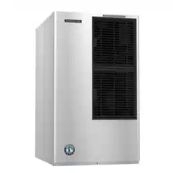
KM-901MAH50
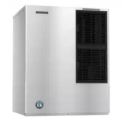
KM-901MRH50
Modular Crescent Cuber
Hoshizaki America, Inc.
Issued: 6-21-2010
INSTRUCTION MANUAL
™
2
IMPORTANT
Only qualied service technicians should install, service, or maintain this
icemaker. No installation, service, or maintenance should be undertaken
until the technician has thoroughly read this Instruction Manual. Likewise, the
owner/manager should not proceed to operate the icemaker until the installer
has instructed them on its proper operation. Failure to install, operate, and
maintain the equipment in accordance with this manual may adversely affect
safety, performance, component life, and warranty coverage.
Hoshizaki provides this manual primarily to assist qualied service technicians in the
installation, maintenance, and service of the icemaker.
Should the reader have any questions or concerns which have not been satisfactorily
addressed, please call, write, or send an e-mail message to the Hoshizaki Technical
Support Department for assistance.
HOSHIZAKI AMERICA, INC.
618 Highway 74 South
Peachtree City, GA 30269
Attn: Hoshizaki Technical Support Department
Phone: 1-800-233-1940 Technical Support
(770) 487-2331
Fax: 1-800-843-1056
(770) 487-3360
E-mail: techsuppor[email protected]
Web Site: www.hoshizaki.com
NOTE: To expedite assistance, all correspondence/communication MUST include the
following information:
•ModelNumber
•SerialNumber
•Completeanddetailedexplanationoftheproblem.
3
CONTENTS
Important Safety Information ................................................................................................. 4
I. Specications ...................................................................................................................... 5
A. Nameplate Rating ......................................................................................................... 5
1. KM-901MAH50 (air-cooled) ...................................................................................... 5
2. KM-901MRH50 (remote air-cooled) ........................................................................ 6
B. Dimensions/Connections .............................................................................................. 7
1. KM-901MAH50 ......................................................................................................... 7
2. KM-901MRH50 ........................................................................................................ 8
II. Installation and Operating Instructions .............................................................................. 9
A. Checks Before Installation ............................................................................................. 9
B. How to Remove Panels ................................................................................................. 9
C. Location ...................................................................................................................... 10
D. Setup ........................................................................................................................... 10
E. Electrical Connection ...................................................................................................11
F. Installation of Remote Condenser Unit ........................................................................ 12
1. Checks Before Installation ...................................................................................... 12
2. Location ................................................................................................................. 12
3. Setup ..................................................................................................................... 13
4. Line Set ................................................................................................................. 13
a) Factory Line Set Installation ............................................................................... 13
b) Field Fabricated Line Set Installation.................................................................. 14
5. Refrigerant Charge (Line Set Exceeding 66 Feet) ................................................. 16
6. Electrical Connection ............................................................................................. 16
7. Stacking Remote Condenser Units ........................................................................ 17
G. Water Supply and Drain Connections ......................................................................... 18
H. Final Checklist ............................................................................................................. 20
I. Startup .......................................................................................................................... 21
III. Cleaning and Maintenance ............................................................................................. 22
A. Cleaning and Sanitizing Instructions .......................................................................... 22
1. Cleaning Procedure ................................................................................................ 22
2. Sanitizing Procedure - Following Cleaning Procedure ........................................... 23
B. Maintenance ................................................................................................................ 24
C. Preparing the Icemaker for Long Storage ................................................................... 24
IMPORTANT
This manual should be read carefully before the icemaker is installed and
operated. Only qualied service technicians should install, service, and
maintain the icemaker. Read the warnings contained in this booklet carefully
as they give important information regarding safety. Please retain this booklet
for any further reference that may be necessary.
4
Important Safety Information
Throughout this manual, notices appear to bring your attention to situations which could
result in death, serious injury, or damage to the unit.
WARNING Indicates a hazardous situation which could result in death or
serious injury.
CAUTION Indicates a situation which could result in damage to the unit.
IMPORTANT Indicates important information about the use and care of the
unit.
WARNING
This icemaker should be destined only to the use for which it has been
expressly conceived. Any other use should be considered improper and
therefore dangerous. The manufacturer cannot be held responsible for
eventual damage caused by improper, incorrect, and unreasonable use.
To reduce the risk of death, electric shock, serious injury, or re, follow
basic precautions including the following:
•Electricalconnectionmustbehard-wiredandmustmeetnational,state,and
local electrical code requirements. Failure to meet these code requirements
could result in death, electric shock, serious injury, re, or severe damage to
equipment.
•Thisunitrequiresanindependentpowersupply.Seethenameplatefor
proper voltage and breaker/fuse size. Failure to use a proper breaker or fuse
can result in a tripped breaker, blown fuse, or damage to existing wiring. This
could lead to heat generation or re.
•THIS UNIT MUST BE GROUNDED. Failure to properly ground this unit could
result in death or serious injury.
•Thisunitshouldbedisassembledorrepairedonlybyqualiedservice
personnel to reduce the risk of electric shock, injury, or re.
•Donotmakeanyalterationstotheunit.Alterationscouldresultinelectric
shock, injury, re, or damage to the unit.
5
I. Specications
A. Nameplate Rating
1. KM-901MAH50 (air-cooled)
See the nameplate for electrical and refrigeration specications. This nameplate is located
on both the rear panel and inside the icemaker.
We reserve the right to make changes in specifications and design without prior notice.
HOSHIZAKI ICE MAKER
MODEL NUMBER KM-901MAH50
SERIAL NUMBER
AC SUPPLY VOLTAGE 230V
FREQUENCY 50HZ
ELECTRICAL CONSUMPTION 2157W
COMPRESSOR CONSUMPTION 1921W
AMPERAGE 9.0A
STARTING AMPERAGE 34A
REFRIGERANT 404A 1375G
WEIGHT 116KG
MAXIMUM OPERATING PRESSURE 2.88MPA
LEAK TIGHTNESS TESTED
MOTOR-COMPRESSOR THERMALLY PROTECTED,
NOT INTENDED FOR OUTDOOR USE!
Hoshizaki America, Inc.
Peachtree City, GA
www.hoshizaki.com
6
See the nameplate for electrical and refrigeration specications. This nameplate is located
on both the rear panel and inside the icemaker.
We reserve the right to make changes in specifications and design without prior notice.
HOSHIZAKI ICE MAKER
MODEL NUMBER KM-901MRH50
SERIAL NUMBER
AC SUPPLY VOLTAGE 230V
FREQUENCY 50HZ
ELECTRICAL CONSUMPTION 2222W
COMPRESSOR CONSUMPTION 1961W
AMPERAGE 9.2A
STARTING AMPERAGE 37A
REFRIGERANT 404A 2420G
WEIGHT 113KG
MAXIMUM OPERATING PRESSURE 2.88MPA
LEAK TIGHTNESS TESTED
MOTOR-COMPRESSOR THERMALLY PROTECTED,
NOT INTENDED FOR OUTDOOR USE!
Hoshizaki America, Inc.
Peachtree City, GA
www.hoshizaki.com
2. KM-901MRH50 (remote air-cooled)
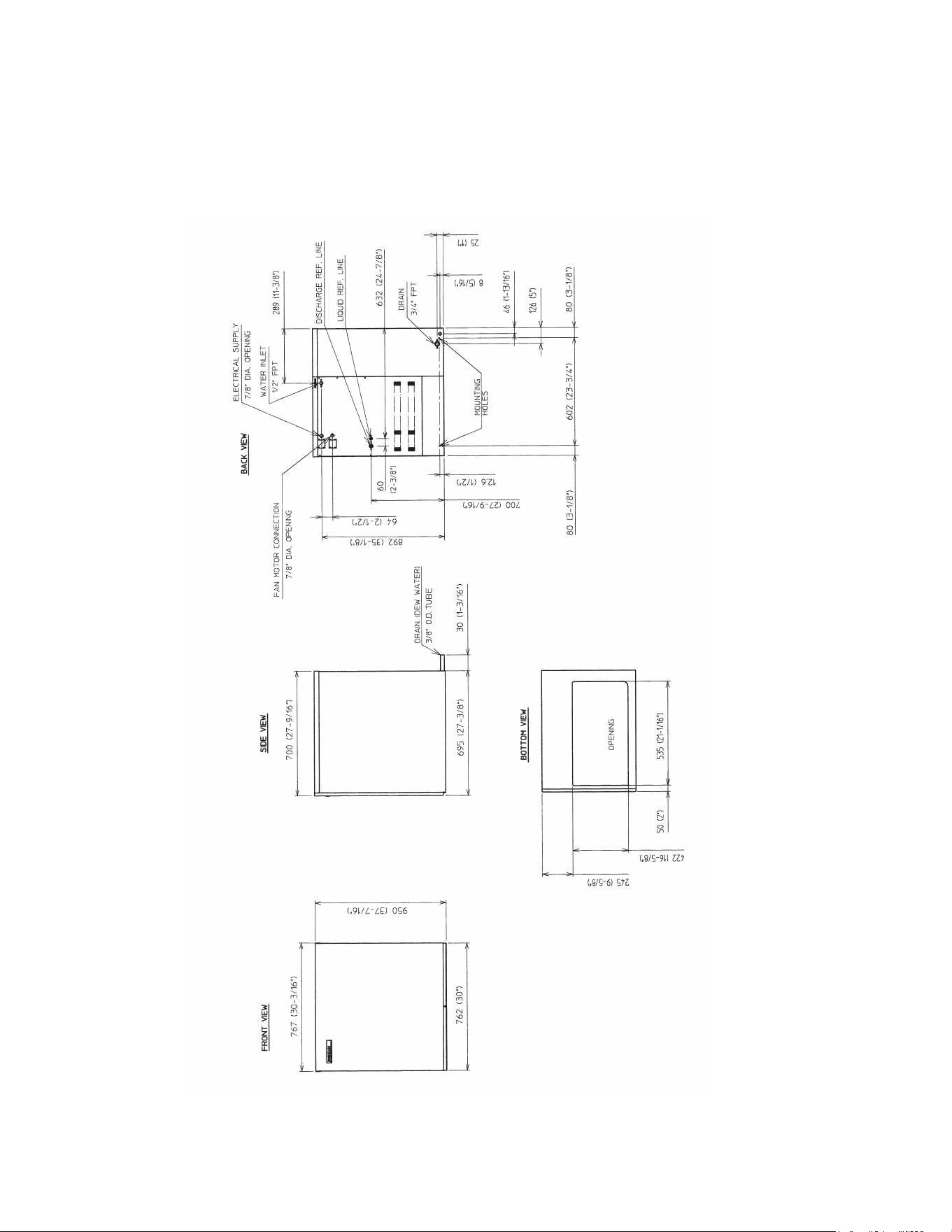
7
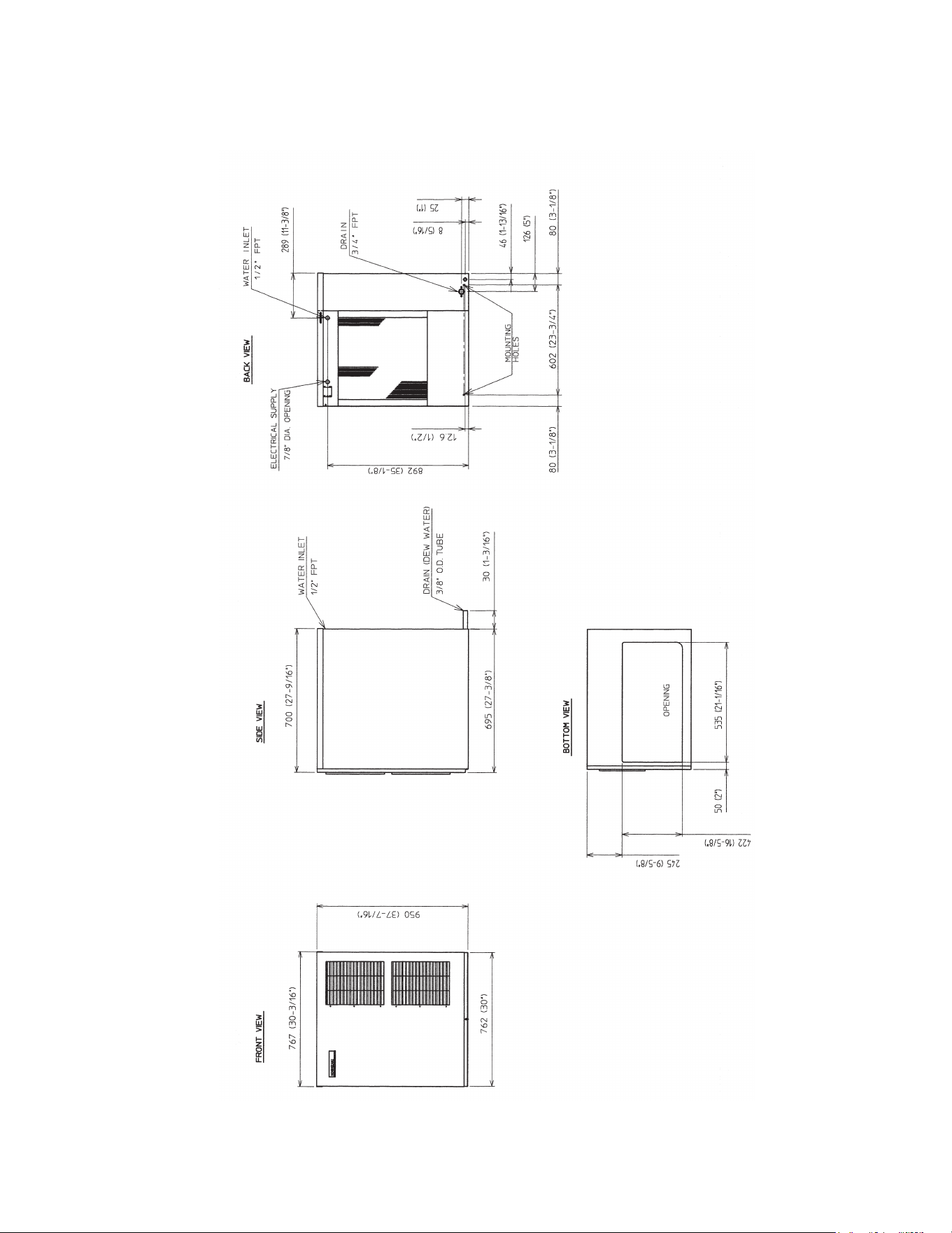
Unit: mm (in.)
B. Dimensions/Connections
1. KM-901MAH50
8
2. KM-901MRH50
Unit: mm (in.)
9
II. Installation and Operating Instructions
WARNING
1. This icemaker must be installed in accordance with applicable national, state,
and local regulations.
2. CHOKING HAZARD: Ensure all components, fasteners, and thumbscrews
are securely in place after installation. Make sure that none have fallen into
the storage bin.
A. Checks Before Installation
•Visuallyinspecttheexterioroftheshippingcontainerandimmediatelyreportany
damage to the carrier. Upon opening the container, any concealed damage should also
be immediately reported to the carrier.
•Removetheshippingcarton,tape,andpackingmaterial.Ifanyareleftintheicemaker,
it will not work properly.
•Removethepanelstopreventdamagewheninstallingtheicemaker.See"II.B.Howto
RemovePanels."
•Removethepackagecontainingtheaccessories.
•Removetheprotectiveplasticlmfromthepanels.Iftheicemakerisexposedtothe
sun or to heat, remove the lm after the icemaker cools.
•Checkthattherefrigerantlinesdonotrubortouchlinesorothersurfaces,andthatthe
fan blade (if applicable) turns freely.
•Checkthatthecompressorissnugonallmountingpads.
•Seethenameplateontherearpanel,andcheckthatyourvoltagesupplied
corresponds with the voltage specied on the nameplate.
•Thisicemakercanbeinstalledonastoragebin30"wideorwider.HoshizakiIce
Storage Bin, Model B-500 series is recommended. For further options, contact your
local Hoshizaki distributor.
•Onremoteair-cooledmodel,aremotecondenserunitisneeded.HoshizakiRemote
Condenser Unit, Model URC-9F is recommended.
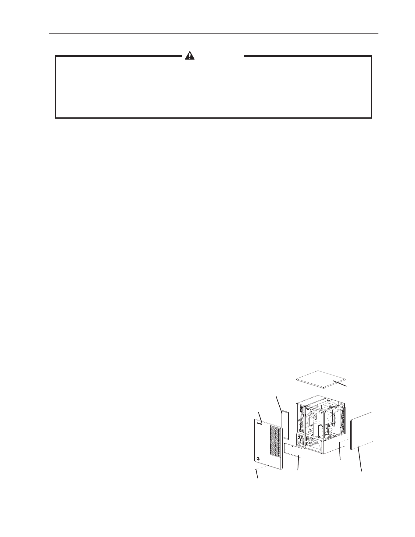
B. How to Remove Panels
See Fig. 1
•FrontPanel:Removethescrew.Liftupand
towards you.
•TopPanel:Liftupatfrontslightly,pushrearward,
and lift off.
•SidePanel(R):Removethescrew.Slideforward
slightly, and lift off.
•InsulationPanel:Liftupslightly,andpulltowards
you.
•BaseCover:Liftupslightly,andpulltowardsyou.
Fig. 1
Top Panel
Front
Panel
Insulation
Panel
Side Panel (R)
Base Cover
Screw
Screw
10
C. Location
CAUTION
1. This icemaker is not intended for outdoor use. Normal operating ambient
temperature should be within 45°F to 100°F (7°C to 38°C); Normal operating
water temperature should be within 45°F to 90°F (7°C to 32°C). Operation
of the icemaker, for extended periods, outside of these normal temperature
ranges may affect icemaker performance.
2. This icemaker will not work at sub-freezing temperatures. To prevent damage
to the water supply line, drain the icemaker if the air temperature is going to
gobelow32°F(0°C).See"III.C.PreparingtheIcemakerforLongStorage."
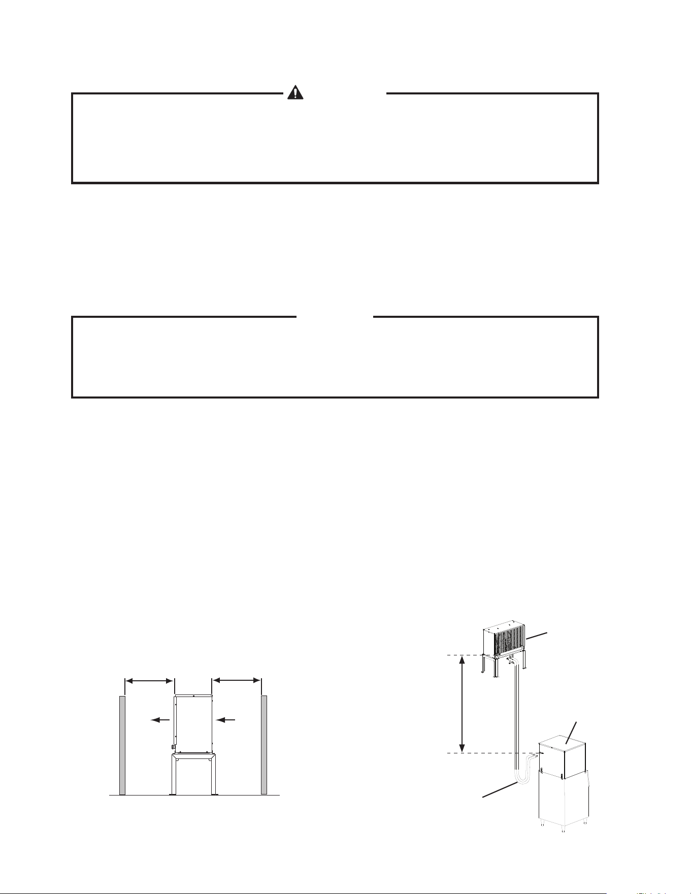
For best operating results:
•Theicemakershouldnotbelocatednexttoovens,grills,orotherhighheatproducing
equipment.
•Thelocationshouldprovidearmandlevelfoundationfortheequipment.
•Allow6"(15cm)clearanceatrear,sides,andtopforproperaircirculationandeaseof
maintenance and/or service should they be required.
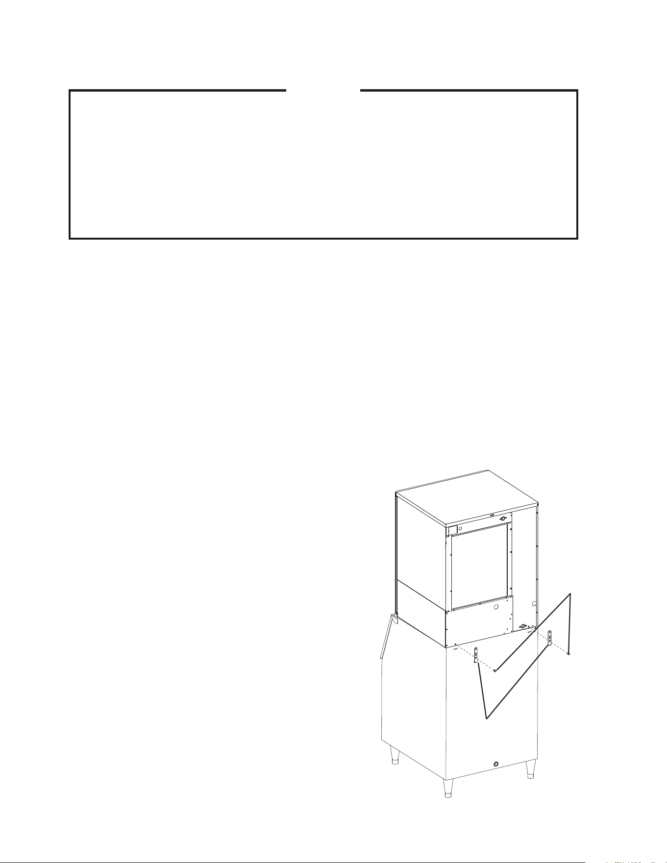
D. Setup
1) Unpack the storage bin, and attach the 4 adjustable legs provided (bin accessory) to
the bottom of the storage bin.
2) Position the storage bin in the selected permanent location.
3) Place the icemaker on top of the storage bin.
4) Secure the icemaker to the storage bin
using the 2 mounting brackets and the
bolts provided. See Fig. 2.
5) Level the icemaker and storage bin in both
the left-to-right and front-to-rear directions.
Adjust the storage bin legs to make the
icemaker level.
6) Replace the panels in their correct
positions.
Fig. 2
Icemaker
Bolts
Mounting
Brackets
Bin
11
E. Electrical Connection
WARNING
For All Models
1. Electrical connection must be hard-wired and must meet national, state, and
local electrical code requirements. Failure to meet these code requirements
could result in death, electric shock, serious injury, re, or severe damage to
equipment.
2. This unit requires an independent power supply. See the nameplate for
proper voltage and breaker/fuse size. Failure to use a proper breaker or fuse
can result in a tripped breaker, blown fuses, or damage to existing wiring.
This could lead to heat generation or re.
3. THIS UNIT MUST BE GROUNDED. Failure to properly ground this unit could
result in death or serious injury.
4. Electrical connection must be made in accordance with the label provided
next to the junction box. See Fig. 3.
Additional Warnings for Remote Air-Cooled Model
5. THE REMOTE CONDENSER UNIT MUST BE GROUNDED. The power
supply and ground wire to the remote condenser unit are supplied from the
icemaker.See"II.F.5.ElectricalConnection."
6. To reduce the risk of electric shock, make all remote condenser unit
connections before connecting the icemaker power supply.
7. On remote air-cooled models, the icemaker should have power for a
minimum of 4 hours prior to startup to prevent compressor damage.
•Usuallyanelectricalpermitandservicesofalicensedelectricianarerequired.
•Themaximumallowablevoltagevariationis±10percentofthenameplaterating.
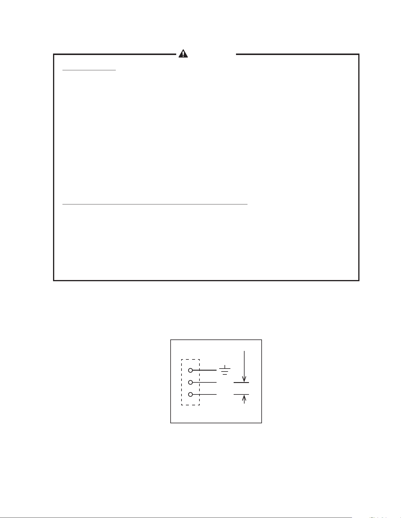
•Theopeningforthepowersupplyconnectionis7/8"DIAtota1/2"tradesizeconduit.
KM-901MAH50
KM-901MRH50
Fig. 3
L
N
230V
4A1169-011
12
F. Installation of Remote Condenser Unit
WARNING
1. Installation of remote condenser unit must be performed by properly trained
and certied service personnel.
2. Failure to install the equipment within these guidelines may adversely affect
safety, performance, component life, and warranty coverage.
1. Checks Before Installation
1) Remove the shipping carton, tape, and packing material.
2) Check that the refrigerant lines do not rub or touch lines or other surfaces, and that the
fan blade moves freely.
2. Location
CAUTION
The remote condenser unit is intended for outdoor use. Normal operating
ambient temperature should be within -20°F to +122°F (-29°C to +50°C).
Operation of the remote condenser unit, for extended periods, outside of this
normal temperature range may affect icemaker performance.
The remote condenser unit must be positioned in a permanent site under the following
guidelines:
•Armandatsite.
•Adryandwellventilatedareawith24"(61cm)clearanceinbothfrontandrearfor
proper air circulation and ease of maintenance and/or service should they be required.
See Fig. 4.
•Themaximumlinelengthforthestandardrefrigerantchargeis66feet.Withadditional
refrigerant,themaximumlinelengthis100feet.Fordetails,see"II.F.5.Refrigerant
Charge(LineSetExceeding66Feet)."
•Themaximumverticaldistancebetweentheremotecondenserunitandtheicemaker
is 33 feet above or 10 feet below the icemaker. These distances are measured tting to
tting. See Fig. 5.
Fig. 4
Min.24"(61cm)Clearance
Air Air
Icemaker
Remote
Condenser
Unit
Service Loop
Max. 33 Feet
Fig. 5
13
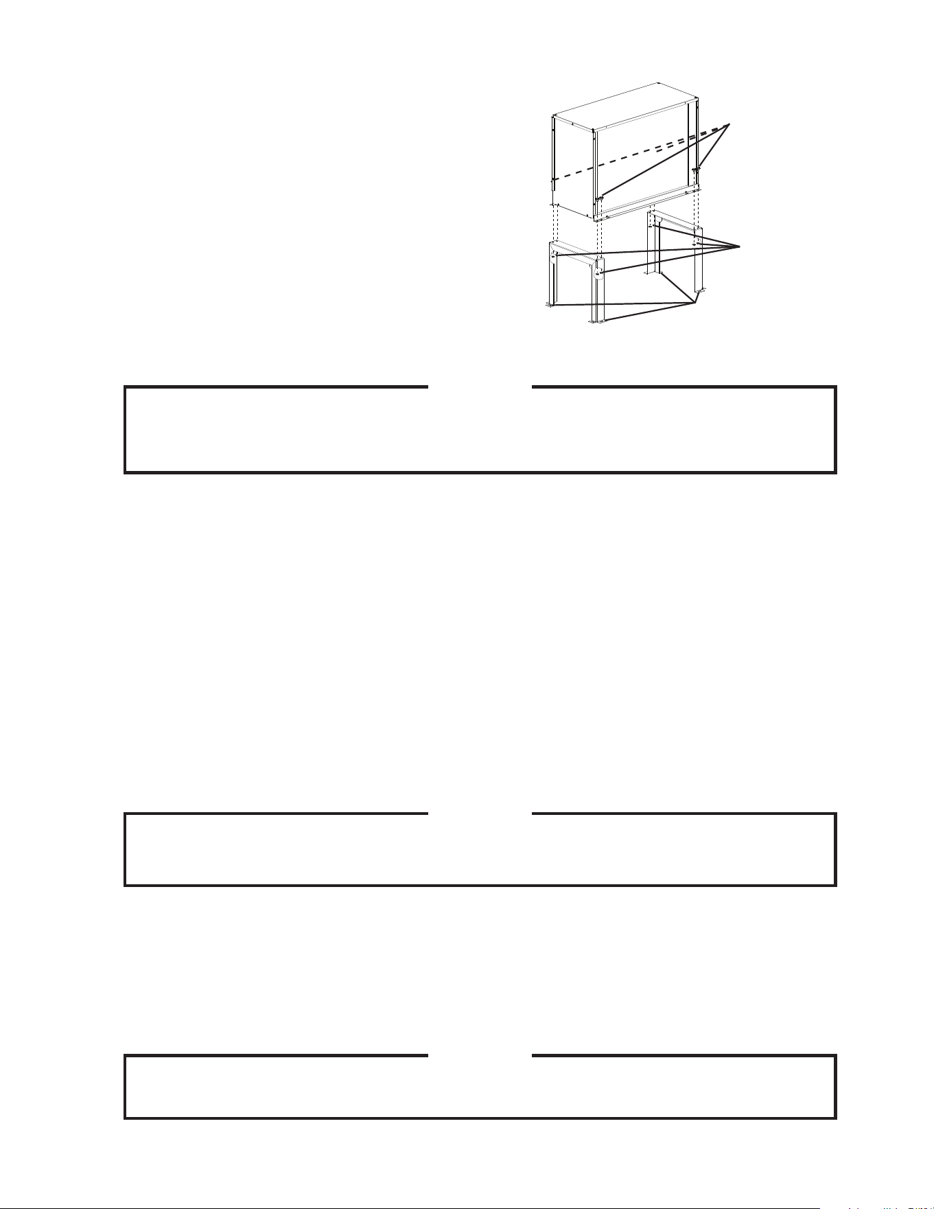
3. Setup
1) Secure the legs to the remote
condenser unit with the 8 bolts and
nuts provided. See Fig. 6.
2) The legs have 8 mounting holes.
Secure the legs to the permanent
site with 8 bolts (not included).
4. Line Set
CAUTION
The icemaker, line set, and remote condenser unit must contain the same
type of refrigerant. Mixing of refrigerants will result in improper operation and
possible damage to the refrigeration system.
•Prechargedfactorylinesets,availableasoptionalequipmentfromHoshizakiAmerica,are
recommended.Fordetails,see"II.F.4.a)FactoryLineSetInstallation."Fieldfabricated
linesetsareallowed.Fordetails,see"II.F.4.b)FieldFabricatedLineSetInstallation."
•Themaximumlinelengthforthestandardrefrigerantchargeis66feet.Withadditional
refrigerant,themaximumlinelengthis100feet.Fordetails,see"II.F.5.Refrigerant
Charge(LineSetExceeding66Feet)."
a) Factory Line Set Installation
1)Routethefactorylineset(1/2"ODdischargelineand3/8"ODliquidline)fromthe
remote condenser unit to the icemaker. Leave a service loop behind the icemaker to
allow the icemaker to be pulled out for service. See Fig. 7. Factory fabricated line sets
are precharged and do not need to be evacuated. If the line set is too long or too short,
see"II.F.4.a)(1)FactoryLineSetModication."
CAUTION
1. Ensure that there are no traps and no kinks in the line set.
2. Do not coil extra line set.
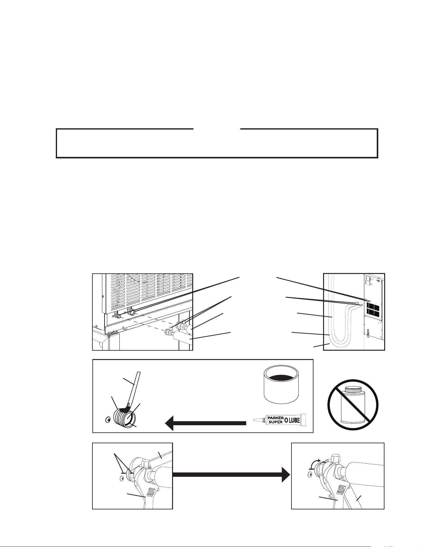
2) Connect the refrigerant lines to the appropriate male ttings on the remote condenser
unit rst and then at the icemaker. Make a proper connection as follows:
a. Remove the protective covers from the male tting and female coupling.
b. Apply Polyol Ester (POE) refrigerant oil or Parker Super O Lube to the entire male
tting, including O-ring, diaphragm, and threads before making the connection. See
Fig. 8.
CAUTION
Do not use thread sealant on the ttings. Use POE refrigerant oil or Parker
Super O Lube only.
Fig. 6
Bolts with Split
Lock Washer
and Flat Washer
Nuts
Mounting Holes
14
c. Make sure the male tting and female coupling are properly aligned, then start the
connection by hand to ensure that it is not cross threaded.
d. Tighten the connection with a wrench until it is tight. At this point, the nut has
covered most of the threads on the male tting.
e. Mark a reference line on the female coupling and the remote condenser unit or
icemaker panel. Using a backup wrench on the back of the female coupling, tighten
the six-sided nut of the female coupling an additional 1/6 turn. See Fig. 9.
3)Ifyoulengthenedthelinesetasoutlinedin"II.F.4.a)(1)FactoryLineSetModication"
anditexceeds66feet,see"II.F.5RefrigerantCharge(LineSetExceeding66Feet)"for
proper charging of the unit.
(1) Factory Line Set Modication
1) Recover the line set charge through the Schrader access ports on the Parker quick
connect couplings and store it in an approved container. Do not discharge the refrigerant
into the atmosphere. Remove the extra line set length or add extra tubing. When adding
extra tubing, insulate the additional copper tubes separately. Braze the connections.
2) Use an electronic leak detector or soap bubbles to check for leaks. Add a trace
of refrigerant to the lines through the Schrader access ports on the Parker quick
connect couplings (if using an electronic leak detector), and then raise the pressure
using nitrogen gas (140 PSIG). WARNING! DO NOT use R-404A as a mixture with
pressurized air for leak testing.
3) Evacuate through the Schrader access ports on the Parker quick connect couplings and
chargewithR-404Arefrigerantvaportoapressureof15to30PSIG.Gotostep2in"II.
F.4.a)FactoryLineSetInstallation."
b) Field Fabricated Line Set Installation
1)Routea1/2"ODcoppertubedischargelineanda3/8"ODcoppertubeliquidline
between the remote condenser unit and the icemaker. Leave a service loop behind the
icemaker to allow the icemaker to be pulled out for service. See Fig. 7.
CAUTION
1. Ensure that there are no traps and no kinks in the line set.
2. Do not coil extra line set. Fabricate the line set to the proper length.
2) Insulate the two copper tubes separately.
3) Install Parker quick connect couplings on each end. OS-QUICK , a universal quick
connect coupling kit available as optional equipment from Hoshizaki America, is
recommended. CAUTION! Before brazing, remove the Schrader valve core from the
access port. When brazing, protect the coupling by using a wet cloth to prevent
the coupling from overheating.
4) Allow the coupling to cool, then replace the Schrader valve core.
5) Use an electronic leak detector or soap bubbles to check for leaks. Add a trace
of refrigerant to the lines through the Schrader access ports on the Parker quick
connect couplings (if using an electronic leak detector), and then raise the pressure
using nitrogen gas (140 PSIG). WARNING! DO NOT use R-404A as a mixture with
pressurized air for leak testing.
15
6) Evacuate through the Schrader access ports on the Parker quick connect couplings
and charge with R-404A refrigerant vapor to a pressure of 15 to 30 PSIG.
7) Connect the refrigerant lines to the appropriate male ttings on the remote condenser
unit rst and then at the icemaker. Make a proper connection as follows:
a. Remove the protective covers from the male tting and female coupling.
b. Apply Polyol Ester (POE) refrigerant oil or Parker Super O Lube to the entire male
tting, including O-ring, diaphragm, and threads, before making the connection.
See Fig. 8.
CAUTION
Do not use thread sealant on the ttings. Use POE refrigerant oil or Parker
Super O Lube only.
c. Make sure the male tting and female coupling are properly aligned, then start the
connection by hand to ensure that it is not cross threaded.
d. Tighten the connection with a wrench until it is tight. At this point, the nut has
covered most of the threads on the male tting.
e. Mark a reference line on the female coupling and the remote condenser unit or
icemaker panel. Using a backup wrench on the back of the female coupling,
tighten the six-sided nut of the female coupling an additional 1/6 turn. See Fig. 9.
8)Ifthelinesetexceeds66feet,see"II.F.5RefrigerantCharge(LineSetExceeding66
Feet)"forproperchargingoftheunit.
Fig. 7
Female Coupling
1/2"ODDischargeLine
(Insulated)
Remote Condenser Unit
3/8"ODLiquidLine
(Insulated)
Icemaker
Male Fitting
Service Loop
Apply POE Oil or
Parker Super O Lube
to Entire Male Fitting
THREAD
SEALANT
Threads
Diaphragm
O-Ring
Fig. 8
Brush
Male Fitting
DO NOT USE
THREAD SEALANT
POLYOL
ESTER
(POE) OIL
PARKER
SUPER
O LUBE
Fig. 9
Backup
Wrench
Reference
Line
1/6
Tu r n
Wrench
Wrench
After Tight, Tighten an
Additional 1/6 Turn
Backup
Wrench
16
5. Refrigerant Charge (Line Set Exceeding 66 Feet)
CAUTION
The icemaker, line set, and remote condenser unit must contain the same
type of refrigerant. Mixing of refrigerants will result in improper operation and
possible damage to the refrigeration system.
The maximum line length for the standard refrigerant charge is 66 feet. Should an
installation require a longer line length, additional refrigerant must be added. Add 0.4 oz. of
R-404A for each foot over 66 feet to a maximum of 100 feet. Hoshizaki Technical Support
is available at 1-800-233-1940 for recommendations.
After weighing in the additional charge, mark the unit's nameplate to show the new correct
total refrigerant charge.
6. Electrical Connection
WARNING
1. Electrical connection must meet national, state, and local electrical code
requirements. Failure to meet these code requirements could result in death,
electric shock, serious injury, re, or severe damage to equipment.
2. THE REMOTE CONDENSER UNIT MUST BE GROUNDED. Install a proper
ground wire from the icemaker to the remote condenser unit. Use wire of
an appropriate gage and outdoor rating. Failure to properly ground the unit
could result in death or serious injury.
3. The remote condenser unit leads must be connected to the fan motor
junction box leads on the icemaker. Use wire of an appropriate gage and
outdoor rating.
4. Do not connect the leads to an external power source. Do not connect the
icemaker's fan motor junction box leads together. Do not allow the leads to
contact the junction box walls.
5. To reduce the risk of electric shock, make all remote condenser unit
connections before connecting the icemaker power supply.
6. On remote air-cooled models, the icemaker should have power for a
minimum of 4 hours prior to startup to prevent compressor damage.
•Usuallyanelectricalpermitandservicesofalicensedelectricianarerequired.
•Theopeningforthepowersupplyconnectionis7/8"DIAtota1/2"tradesizeconduit.
1) Remove the louver panel. See Fig. 10.
2) Remove the junction box cover on the remote condenser unit. Remove the fan motor
junction box cover on the icemaker.
3) Install a ground wire from the icemaker to the remote condenser unit. Use wire of an
appropriate gage and outdoor rating.
17
4) Connect the fan motor leads in the junction box of the remote condenser unit to the fan
motor leads in the fan motor junction box of the icemaker. Use wire of an appropriate
gage and outdoor rating.
5) Replace the junction box covers and the louver panel in their correct positions.
7. Stacking Remote Condenser Units
1) Install the lower remote condenser unit as described earlier in this section.
2) Place the upper remote condenser unit on top of the lower. See Fig. 11.
3) Secure the upper remote condenser unit to the lower remote condenser unit with the
4 screws provided.
4) Install refrigerant lines and make electrical connection as described earlier in this
section.
Fig. 10
Screws
Louver Panel
Junction Box
Cover
Remote Condenser Unit
Icemaker
Screw
Fan Motor Junction
Box Cover
Fig. 11
Upper Remote
Condenser Unit
Screws
Lower Remote
Condenser Unit
Screws
18
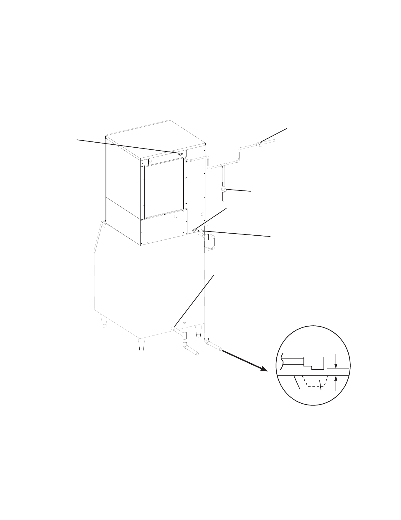
G. Water Supply and Drain Connections
See Fig. 12
WARNING
1. Water supply and drain connections must be installed in accordance with
applicable national, state, and local regulations.
2. Normal operating water temperature should be within 45°F to 90°F (7°C
to 32°C). Operation of the icemaker, for extended periods, outside of this
normal temperature range may affect icemaker performance.
3. To prevent damage to equipment, do not operate the icemaker when the
water supply is off, or if the pressure is below 10 PSIG. Do not run the
icemaker until the proper water pressure is reached.
•Aplumbingpermitandservicesofalicensedplumbermayberequiredinsomeareas.
•Externallters,strainers,orsoftenersmayberequireddependingonwaterquality.
Contact your local Hoshizaki distributor for recommendations.
•Watersupplypressureshouldbeaminimumof10PSIGandamaximumof113PSIG.If
the pressure exceeds 113 PSIG, the use of a pressure reducing valve is required.
•Theicemakerandcondensationdrainline(s)andstoragebindrainlinemustberun
separately.
•Drainlinesmusthave1/4"fallperfoot(2cmper1m)onhorizontalrunstogetagood
ow.Aventedteeconnectionisalsorequiredforproperow.
•Drainlinesshouldnotbepipeddirectlytothesewersystem.Anairgapofaminimumof
2 vertical inches (5 cm) should be between the end of the drain pipes from the icemaker,
condensationdrain,andstoragebinandtheoordrain.
19
1. Icemaker
•Icemakerwatersupplyinletis1/2"femalepipethread(FPT).Aminimumof3/8"OD
copper tubing is recommended for the icemaker water supply line.
•Anicemakerwatersupplylineshut-offvalveanddrainvalveshouldbeinstalled.
•Icemakerdrainoutletis3/4"FPT.Aminimumof3/4"ODhardpipeisrecommendedfor
theicemakerdrainline.Condensationdrainoutletis3/8"ODtube.Thecondensation
drain line can be connected to the icemaker drain line or can be run separately.
Fig. 12
KM-901MAH50 and KM-901MRH50
Separate piping to approved drain.
Leave a two-inch (5 cm) vertical air
gap between the end of each pipe
and the drain.
Icemaker Water Supply Line
Shut-OffValve
Icemaker Water Supply Line
DrainValve
Icemaker
Icemaker
Water Supply
Inlet
1/2"FPT
Bin Drain Outlet
3/4"FPT
Two-inch
(5 cm) air
gap
Floor
Drain
Icemaker
Drain Outlet
3/4"FPT
Bin
Condensation
Drain Outlet
3/8"ODTube
20
H. Final Checklist
WARNING
CHOKING HAZARD: Ensure all components, fasteners, and thumbscrews are
securely in place after installation. Make sure that none have fallen into the
storage bin.
1) Is the icemaker level?
2) Is the icemaker in a site where the ambient temperature is within 45°F to 100°F (7°C to
38°C) and the water temperature within 45°F to 90°F (7°C to 32°C) all year around?
3)Isthereatleast6"(15cm)clearanceatsides,rear,andtopoftheicemakerforproper
air circulation and ease of maintenance and service?
4) Have the shipping carton, tape, and packing material been removed from the
icemaker? Is the cube guide in the correct position?
5) Are all components, fasteners, and thumbscrews securely in place?
6) Have all electrical and water connections been made? Do electrical and water
connections meet all national, state, and local code and regulation requirements?
7) Has the power supply voltage been checked or tested against the nameplate rating?
Has a proper ground been installed to the icemaker? On remote air-cooled model, has
a proper ground also been installed to the remote condenser unit?
8) Are the water supply line shut-off valve and drain valve installed? Has the water
supply pressure been checked to ensure a minimum of 10 PSIG and a maximum of
113 PSIG?
Note: The icemaker may stop running when the water supply is off, or if the pressure
is below 10 PSIG. When the proper water pressure is reached, the icemaker
automatically starts running again.
9) Are the compressor hold-down bolts snug? Have the refrigerant lines been checked
to make sure they do not rub or touch other lines or surfaces? Has the fan blade (if
applicable) been checked to make sure it turns freely?
10) On remote air-cooled model, is the refrigerant line set tightened and free of kinks?
11) On remote air-cooled model, has the icemaker power supply been on for a minimum of
4 hours?
12) Has the end user been given the instruction manual, and instructed on how to operate
the icemaker and the importance of the recommended periodic maintenance?
13) Has the end user been given the name and telephone number of an authorized service
agent?
14) Has the warranty card been lled out and forwarded to the factory for warranty
registration?
21
I. Startup
WARNING
1. All parts are factory-adjusted. Improper adjustments may adversely affect
safety, performance, component life, and warranty coverage.
2. If the icemaker is turned off, wait for at least 3 minutes before restarting the
icemaker to prevent damage to the compressor.
3. To prevent damage to the water pump seal, do not operate the icemaker with
thecontrolswitchinthe"WASH"positionwhenthewatertankisempty.
4. At startup, conrm that all internal and external connections are free of leaks.
5. On remote air-cooled model, the icemaker should have power for a minimum
of 4 hours prior to startup to prevent compressor damage.
1) Open the water supply line shut-off valve.
2) Remove the front panel.
3)Movethecontrolswitchonthecontrolboxtothe"ICE"position.
4) Replace the front panel in its correct position.
5) Turn on the power supply, and allow the icemaker to operate for a total of 10 minutes.
6) Turn off the power supply, then remove the front panel.
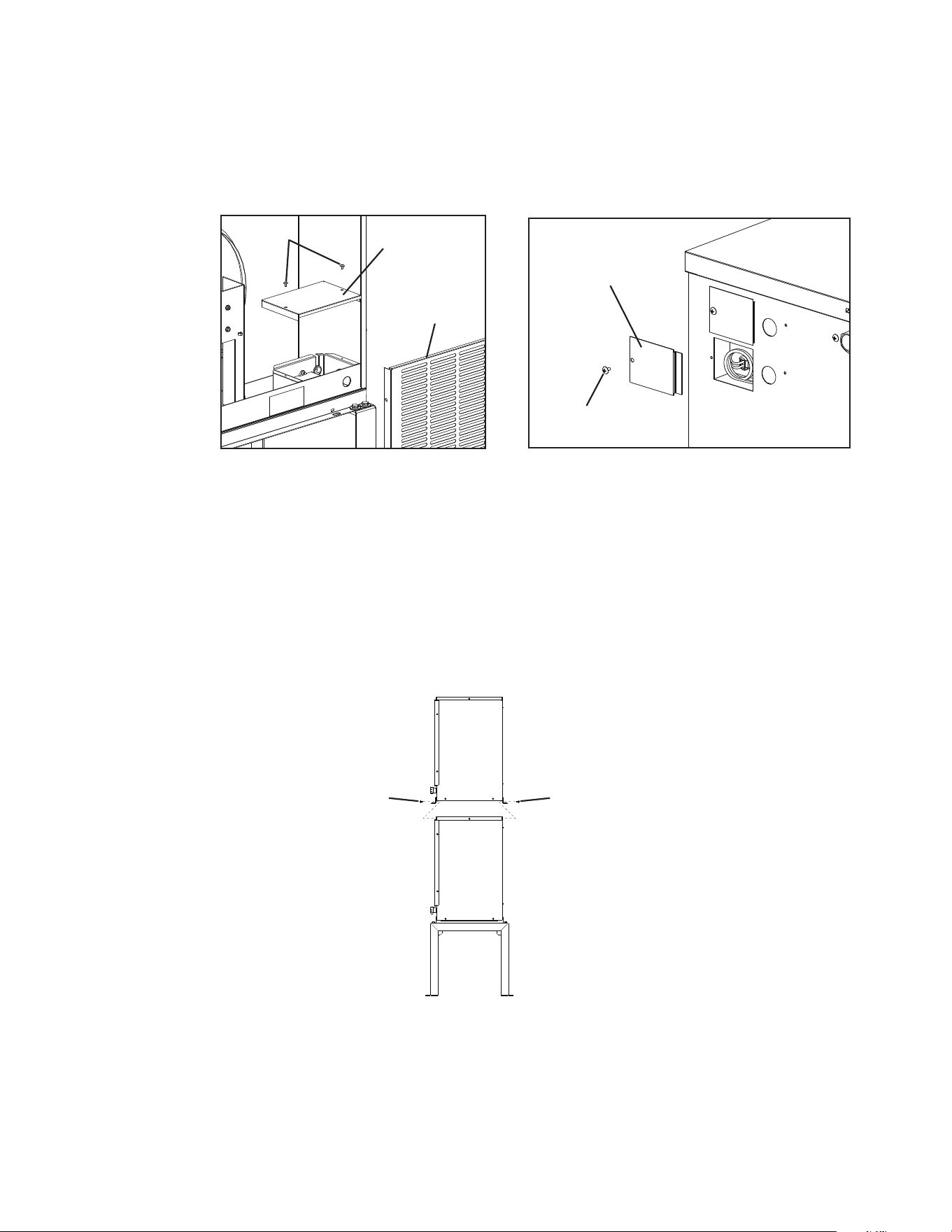
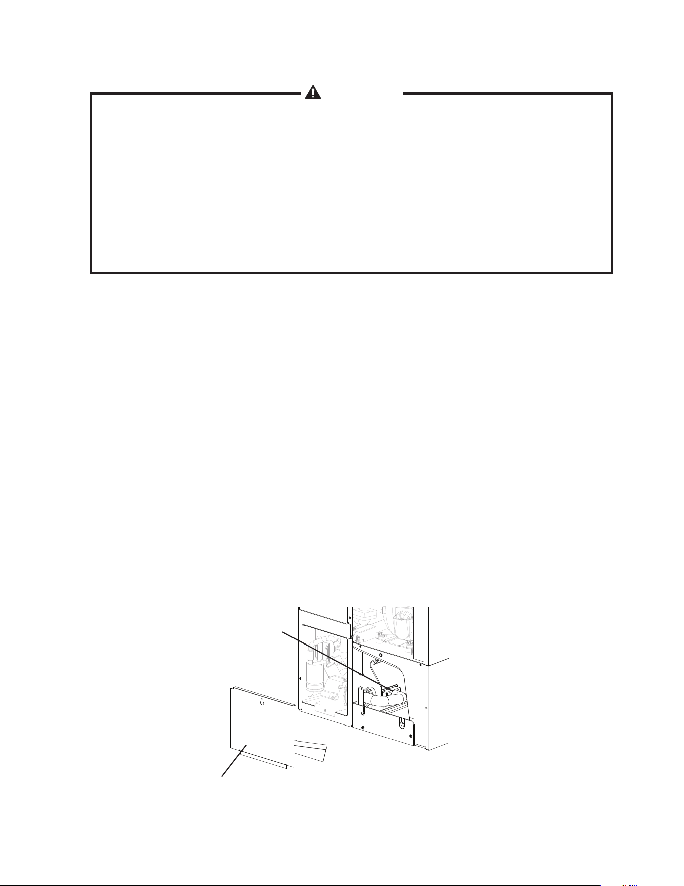
7) Remove the base cover, then disconnect one end of the pump tubing to drain the water
tank. See Fig. 13.
8) After the water tank has drained, reconnect the pump tubing.
9) Clean the storage bin liner using a neutral cleaner. Rinse thoroughly after cleaning.
10) Replace the base cover and the front panel in their correct positions.
11) Turn on the power supply to start the automatic icemaking process.
12) To conrm bin control operation, press and hold the bin control's actuator paddle during
the rst 5 minutes of the freeze cycle. The icemaker should shut down in approximately
15 seconds.
Fig. 13
Disconnect This
End of Pump
Tubing to Drain
Water Tank
Base Cover
22
III. Cleaning and Maintenance
WARNING
CHOKING HAZARD: Ensure all components, fasteners, and thumbscrews are
securely in place after any cleaning or maintenance is done to the unit. Make
sure that none have fallen into the storage bin.
A. Cleaning and Sanitizing Instructions
Hoshizaki recommends cleaning and sanitizing this unit at least once a year. More
frequent cleaning and sanitizing, however, may be required in some existing water
conditions.
WARNING
1. To prevent injury to individuals and damage to the icemaker, do not use
ammonia type cleaners.
2. Carefully follow any instructions provided with the bottles of cleaning and
sanitizing solution.
3. Always wear liquid-proof gloves and goggles to prevent the cleaning and
sanitizing solutions from coming into contact with skin or eyes.
4. To prevent damage to the water pump seal, do not operate the icemaker with
thecontrolswitchinthe"WASH"positionwhenthewatertankisempty.
1. Cleaning Procedure
1)Dilute16.oz.(473ml)ofHoshizaki"ScaleAway"with3gal.(11l)ofwarmwater.
2) Remove all ice from the evaporator and the storage bin.
Note: To remove cubes on the evaporator, turn off the power supply and turn it back on
after 3 minutes. The harvest cycle starts and the cubes will be removed from the
evaporator.
3) Turn off the power supply.
4) Remove the front panel, then remove the insulation panel by lifting up the panel slightly
and pulling it towards you.
5) Remove the base cover, then disconnect one end of the pump tubing to drain the water
tank. See Fig. 13. After the water tank has drained, reconnect the pump tubing.
6)Inbadorseverewaterconditions,cleantheoatswitchassemblyasdescribedbelow.
Otherwise, continue to step 7.
a.Disconnecttheventtubeandtheushtubefromthetopoftheoatswitch,then
removetheoatswitchassembly.Removetherubberbootfromthebottomofthe
assembly.
b.Removetheretainerrodfromthebottomoftheoatswitchhousing,thenremove
theoat.Becarefulnottobendtheretainerrodexcessivelywhenremovingit.
c.Wipedowntheoatswitchassembly'shousing,shaft,oat,andretainerrodwith
cleaning solution. Clean the inside of the rubber boot and hose with cleaning
solution. Rinse the parts thoroughly with clean water.
d.Reassembletheoatswitchassemblyandreplaceitandtherubberbootintheir
correctpositions.Reconnecttheventtubeandtheushtube.

23
7) Pour the cleaning solution into the water tank.
8)Movethecontrolswitchonthecontrolboxtothe"WASH"position.
9) Replace the insulation panel and the front panel in their correct positions.
10) Turn on the power supply to start the washing process.
11) Turn off the power supply after 30 minutes.
12) Remove the front panel.
13) Disconnect one end of the pump tubing to drain the water tank. After the water tank has
drained, reconnect the pump tubing.
14)Movethecontrolswitchtothe"ICE"position.
15) Replace the front panel in its correct position.
16) Turn on the power supply to ll the water tank with water.
17) Turn off the power supply after 3 minutes.
18) Remove the front panel.
19)Movethecontrolswitchtothe"WASH"position.
20) Replace the front panel in its correct position.
21) Turn on the power supply to rinse off the cleaning solution.
22) Turn off the power supply after 5 minutes.
23) Remove the front panel.
24) Disconnect one end of the pump tubing to drain the water tank. After the water tank has
drained, reconnect the pump tubing.
25) Repeat steps 14 through 24 three more times to rinse thoroughly.
Note:Ifyoudonotsanitizetheicemaker,gotostep10in"2.SanitizingProcedure."
2. Sanitizing Procedure - Following Cleaning Procedure
1) Dilute a 5.25% sodium hypochlorite solution (chlorine bleach) with warm water. (Add
1.5.oz.(44ml)ofsanitizerto3gal.(11l)ofwater.)
2) Remove the insulation panel.
3) Pour the sanitizing solution into the water tank.
4) Replace the insulation panel and the front panel in their correct positions.
Note:Makesurethecontrolswitchisinthe"WASH"position.
5) Turn on the power supply to start the sanitizing process.
6) Turn off the power supply after 15 minutes.
7) Remove the front panel.
8) Disconnect one end of the pump tubing to drain the water tank. After the water tank has
drained, reconnect the pump tubing.
9)Repeatsteps14through24in"1.CleaningProcedure"twotimestorinsethoroughly.
10)Movethecontrolswitchtothe"ICE"position.
11) Replace the front panel and the base cover in their correct positions.
24
12) Clean the storage bin liner using a neutral cleaner. Rinse thoroughly after cleaning.
13) Turn on the power supply to start the automatic icemaking process.
B. Maintenance
This icemaker must be maintained individually, referring to the instruction manual and
labels provided with the icemaker.
WARNING
1. Only qualied service technicians should attempt to service or maintain this
icemaker.
2. Disconnect power before performing service or maintenance.
1. Stainless Steel Exterior
To prevent corrosion, wipe the exterior occasionally with a clean, soft cloth. Use a damp
cloth containing a neutral cleaner to wipe off oil or dirt buildup.
2. Storage Bin and Scoop
•Washyourhandsbeforeremovingice.Usetheplasticscoopprovided(binaccessory).
•Thestoragebinisforiceuseonly.Donotstoreanythingelseinthestoragebin.
•Cleanthescoopandthestoragebinlinerusinganeutralcleaner.Rinsethoroughly
after cleaning.
3. Air Filters (air-cooled model)
Plastic mesh air lters remove dirt and dust from the air, and keep the condenser from
getting clogged. As the lters get clogged, the icemaker's performance will be reduced.
Check the lters at least twice a month. When clogged, use warm water and a neutral
cleaner to wash the lters.
4. Condenser (air-cooled and remote air-cooled models)
Check the condenser once a year, and clean the coil if required by using a brush or
vacuum cleaner. More frequent cleaning may be required depending on location.
C. Preparing the Icemaker for Long Storage
CAUTION
1. When storing the icemaker for an extended time or in sub-freezing
temperatures, follow the instructions below to prevent damage.
2. To prevent damage to the water pump seal, do not operate the icemaker with
thecontrolswitchinthe"WASH"positionwhenthewatertankisempty.
When the icemaker is not used for two or three days under normal conditions, it is sufficient
tomovethecontrolswitchtothe"OFF"position.Whenstoringtheicemakerforan
extended time or in sub-freezing temperatures, follow the instructions below.
1. Remove the water from the icemaker water supply line:
1) Turn off the power supply, then remove the front panel.
2)Movethecontrolswitchonthecontrolboxtothe"OFF"position.

25
3) Close the icemaker water supply line shut-off valve, then open the icemaker water
supply line drain valve.
4) Allow the line to drain by gravity.
5) Attach a compressed air or carbon dioxide supply to the icemaker water supply line
drain valve.
6)Movethecontrolswitchtothe"ICE"position.
7) Replace the front panel in its correct position, then turn on the power supply.
8) Blow the icemaker water supply line out using the compressed air or carbon dioxide
supply.
9) Close the icemaker water supply line drain valve.
2. Drain the water tank:
1) Turn off the power supply, then remove the front panel.
2)Movethecontrolswitchtothe"OFF"position.
3) Remove the base cover, then disconnect one end of the pump tubing to drain the water
tank. See Fig. 13. After the water tank has drained, reconnect the pump tubing.
4) Replace the base cover and the front panel in their correct positions.
5) Remove all ice from the storage bin. Clean the storage bin liner using a neutral cleaner.
Rinse thoroughly after cleaning.

26
618 Hwy. 74 S., Peachtree City, GA 30269 USA TEL (770) 487-2331 FAX (770) 487-3360 www.hoshizaki.com 91A1JP10A
HOSHIZAKI AMERICA, INC.