MILWAUKEE TOOL
l
www.milwaukeetool.com
13135 W. LISBON RD., BROOKFIELD, WI 53005
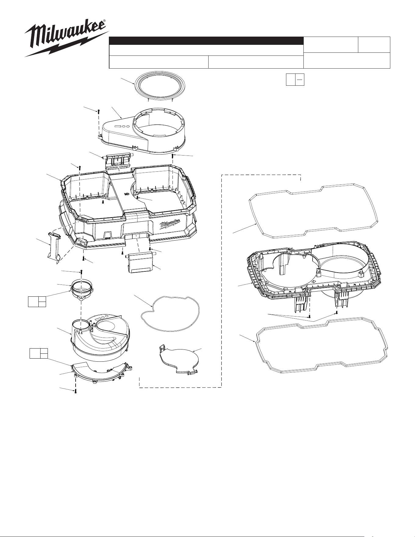
Drwg. 2
FIG. PART NO. DESCRIPTION OF PART NO. REQ.
1 --------------- Latch (2)
2 --------------- Handle (1)
3 --------------- Inlet Assembly (1)
4 --------------- Cyclone Cover (1)
5 --------------- Inlet Plate (1)
6 43-44-0004 Oulet Cover Seal (1)
7 --------------- Outlet Cover (1)
8 --------------- Housing (1)
9 05-88-0042 M4 x 10mm PH Tamperproof Screw (4)
10 --------------- Gasket (1)
11 31-15-0403 Cyclone Plate (1)
12 --------------- Housing Gasket (1)
13 --------------- Bottom Plate (1)
14 43-44-0003 Bottom Plate Gasket (1)
15 05-88-0003 M4 x 16mm PH Tamperproof Screw (38)
20 14-46-0735 Inlet Kit (1)
21 14-46-0736 Inlet Plate Kit (1)
22 12-20-9901 Service Nameplate (not shown) (1)
BULLETIN NO.
PN0004827
SERVICE PARTS LIST
CATALOG NO. 0990-20
REVISED BULLETIN
SPECIFY CATALOG NO. AND SERIAL NO. WHEN ORDERING PARTS
NEXUS™ DEDICATED DEBRIS SEPARATOR
SERIAL NO.
DATE
June 2025
WIRING INSTRUCTION
R43A
0
00
EXAMPLE:
Component Parts (Small #)
Are Included When Ordering
The Assembly (Large #).
6
7
1
8
9
(2x)
15
(2x)
1
9
(2x)
2
15
(2x)
15
(3x)
3
10
4
5
15
(8x)
11
12
13
9
(4x)
14
20
3
15
21
5
15
15
(15x)
15
(5x)
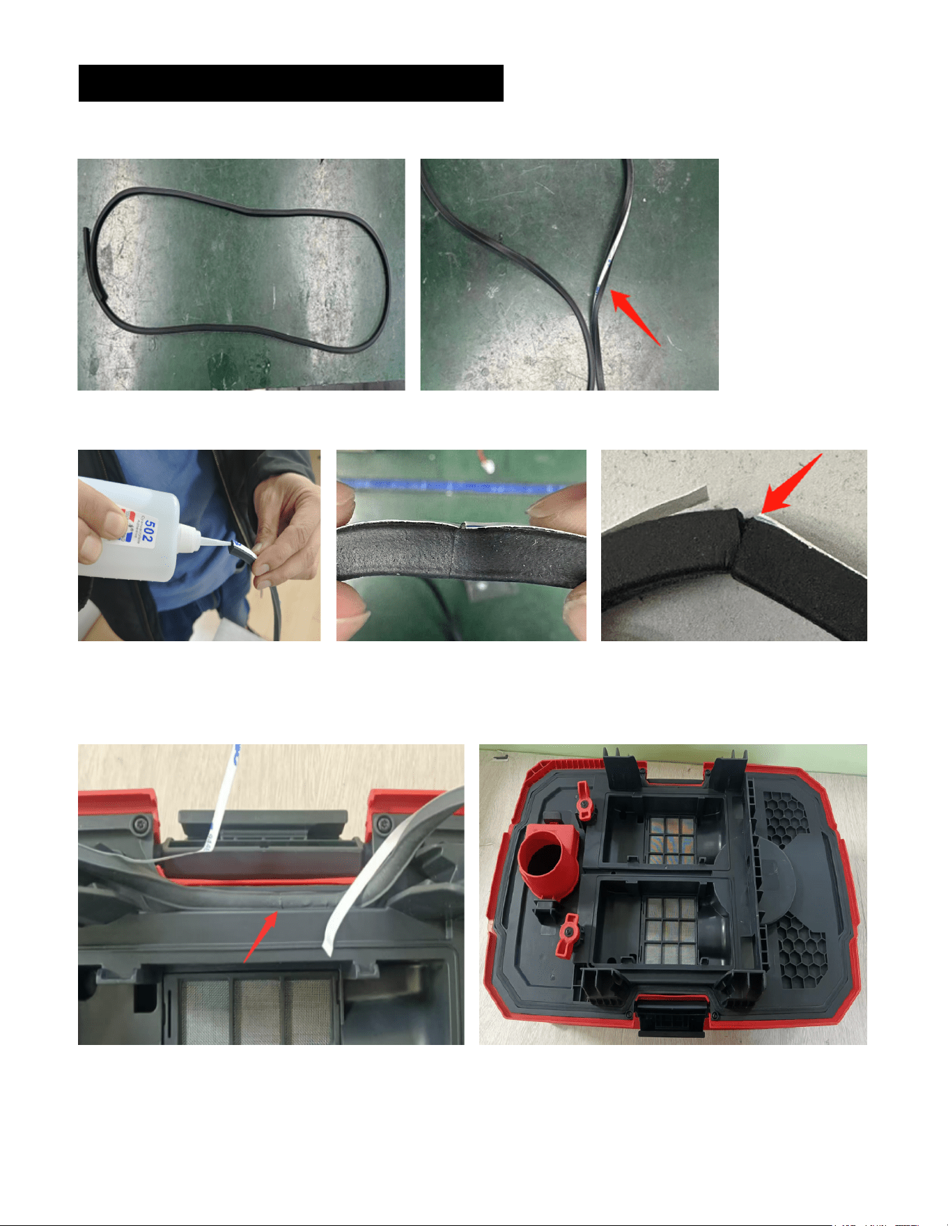
BOTTOM SEAL REPLACEMENT INSTRUCTIONS
2. Remove seal and unroll. Make sure seal is not twisted. (FIG. 2-1 is correct, FIG. 2-2 is incorrect).
FIG. 2-1
4. Start installation with the joined end aligned with the center of the latch (FIG. 4-1). Peel off the
protective film while attaching the seal into the slot of the base (FIG. 4-2).
NOTE: Make sure there is no lifting or breakage of the seal.
1. Remove the original seal and clean the groove.
FIG. 3-1 FIG. 3-2 FIG. 3-3
3. Apply small amount of glue to one end of seal, coating evenly (FIG. 3-1). Align and press the ends
together, holding for at least 5 seconds to ensure adhesion. Verify ends are aligned and attached.
(FIG. 3-2 is correct, FIG. 3-3 is incorrect.)
FIG. 4-1 FIG. 4-2
FIG. 2-2