USER MANUAL
Gas KoolGriddle
Models:
KM-GG1 18M | KM-GG2-24M | KM-GG3-36M | KM-GG4-48M
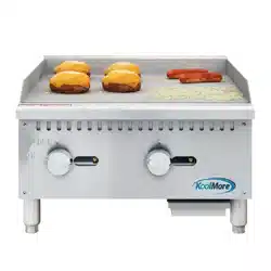
KoolMore KoolGriddle Collection
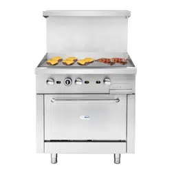
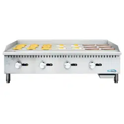
Commercial Gas Griddle
KM-GG4-48M
Stay informed with the latest information
for your KoolMore KoolGriddle Appliance.
Scan the QR code above to access the most recent user manual
on our website, which is constantly being updated and improved.
If you need any assistance or have questions, our customer
support team is here to help.
Updated On Sep 07 2023
Version: 1.0

Your safety is our top priority. Before installing and using this equipment, please read and follow
these important warnings and guidelines:
• Flammable Liquids: Keep all flammable liquids like gasoline away from this equipment
and other appliances.
• Proper Installation is Key: Incorrect installation, adjustments, alterations, service, or
maintenance can lead to property damage, injuries, or even fatalities.
• Read the Instructions: Before installing or servicing this equipment, carefully go through
the installation and maintenance instructions.
• Qualified Installation: Have a skilled installer set up the equipment following federal,
state, and local regulations.
• Stable Support: Always ensure all four legs are securely attached before using the equip-
ment.
• Suitable Location: This equipment is intended for use in non-combustible areas only.
• Maintain Airflow: Avoid blocking the flow of combustion and ventilation air around the
equipment.
• No Liquid on Controls: Do not spray any liquids or cleaning agents on the equipment's
controls or exterior.
• Cool Down Before Cleaning or Moving: Let hot parts cool down before cleaning or relo-
cating them.
• Level Ground: Operate this equipment on a flat and level surface.
• Never Leave Unattended: Do not leave the equipment unattended while it's in use.
• Gas Line Precaution: Prevent loose dirt or metal particles from entering the gas lines, as
it can damage the valve and impact its operation.
• Gas Odor: If you detect a gas odor, follow the gas supplier's instructions. Do not attempt
to ignite the burner and avoid using a telephone nearby.
• Grate Safety: Never try to move the grate while cooking is in progress.
Please adhere to these safety precautions to ensure the safe and proper operation of your
equipment. If you have any questions or concerns, consult with a qualified professional.
SAFETY

2
Equipment Setup:
Unpacking: Take off all packing materials, tape, and any protective plastic from the equip-
ment.
Choose the Right Spot: Position the equipment at your preferred location and adjust its
height as needed.
Attach the Legs: Install all four (4) legs securely onto the equipment.
Prep for Use: Before using the equipment, make sure it is cleaned and completely dry.
Installation Instructions:
Unpacking & Inspection:
1. Carefully remove the appliance from its packaging. Take off all protective plastic film,
packing materials, and accessories before proceeding with installation.
2. Prior to installation, thoroughly review the instructions in this manual and the included
Installation Instruction Sheet.
Clearance and Equipment Positioning:
• This equipment should only be installed next to non-combustible surfaces, with a mini-
mum 6-inch clearance from all sides.
• Maintain a 6-inch distance from other equipment.
• Ensure the equipment is fitted with 4-inch legs and placed on a non-combustible surface.
Air Supply and Ventilation:
• Keep the area in front and around the equipment clear to prevent any obstruction of
combustion and ventilation airflow.
• Maintain adequate clearance in front of and on the sides of the equipment to allow for
servicing and proper ventilation.
SETUP & INSTALLATION
Adequate clearance must be maintained at a
equipment for servicing and proper ventilatio
PRESSURE REGUL A T O R
• All commercial cooking equipment must
service line for safe and ef fic ie nt ope ration.
is adaptable for both Natural gas and LP gas.
• Regulator specifications: ¾” NPT inlet and
Gas standard and may be converted by qua
10” WC.
GAS CONVERSION:
Pressure Regulator:
• All commercial cooking equipment requires a pressure
regulator on the incoming service line for safe and efficient
operation.
• The provided regulator is adaptable for both Natural Gas
and LP Gas.
• Regulator specifications: ¾” NPT inlet and outlet, factory
adjusted for 4” WC Natural Gas standard, and can be
converted by qualified personnel for Propane at 10” WC.
Pressure Check:
Before connecting the regulator, check incoming line pressure. Regulator handles a maximum of ½ PSI (14" WC).
If pressure exceeds this, use an additional regulator. Make sure the arrow points downstream for gas flow safety.
Gas Conversion:
• Conversion from Natural Gas to Liquid Propane (LP) or vice versa can only be performed by the
factory or its authorized service agent.
• Ensure the correct orifice sizes of the spuds are provided.
• Natural Gas Orifice: #37
• Liquid Propane Gas Orifice: #51
• Orifice size is indicated on the spud.
Lighting the Pilot:
1. Before attempting to light the pilots, turn off the main gas valve to the equipment and wait for 5
minutes to allow the gas to clear.
2. Turn off all gas control knobs.
3. Turn on the control valve and ignite all pilots.
4. The pilot burner should be ignited at the end of the tube. Hold an ignition source through the
pilot light hole in the front panel at the pilot tube. Remove the ignition source when the flame
ignites.
5. To shut down the equipment, turn off the main gas valve.
It's normal for some smoke to appear during initial use as the rust preventative coating burns off.
Allow the equipment to "burn in" for at least 15 minutes before the first use.
Pilot Flame Regulation:
• The pilot flame is factory adjusted. If adjustment is needed, make the pilot flame as small as
possible but high enough to immediately light the burner when the burner valve is turned to the
highest setting. Access to the pilot flame adjustment screw is obtained by removing the front
panel.
Burner Adjustment:
• Remove the front panel for access. Turn the burner valve knob to the highest setting.
• Gradually decrease the mixing ring aperture to achieve a soft blue flame with luminous tips.
• Slowly increase the opening until the yellow tips disappear, and a hard blue flame is obtained.
Follow these instructions for the safe and efficient installation of your equipment.

Equipment Setup:
Unpacking: Take off all packing materials, tape, and any protective plastic from the equip-
ment.
Choose the Right Spot: Position the equipment at your preferred location and adjust its
height as needed.
Attach the Legs: Install all four (4) legs securely onto the equipment.
Prep for Use: Before using the equipment, make sure it is cleaned and completely dry.
Installation Instructions:
Unpacking & Inspection:
1. Carefully remove the appliance from its packaging. Take off all protective plastic film,
packing materials, and accessories before proceeding with installation.
2. Prior to installation, thoroughly review the instructions in this manual and the included
Installation Instruction Sheet.
Clearance and Equipment Positioning:
• This equipment should only be installed next to non-combustible surfaces, with a mini-
mum 6-inch clearance from all sides.
• Maintain a 6-inch distance from other equipment.
• Ensure the equipment is fitted with 4-inch legs and placed on a non-combustible surface.
Air Supply and Ventilation:
• Keep the area in front and around the equipment clear to prevent any obstruction of
combustion and ventilation airflow.
• Maintain adequate clearance in front of and on the sides of the equipment to allow for
servicing and proper ventilation.
Product parameters table
times in front of and at the sides of the
.
ave a pressure regulator on the incoming
The regulator provided for this equipment
outlet, factory adjusted for 4” WC Natural
fied personnel to be used for Propane at
Pressure Regulator:
• All commercial cooking equipment requires a pressure
regulator on the incoming service line for safe and efficient
operation.
• The provided regulator is adaptable for both Natural Gas
and LP Gas.
• Regulator specifications: ¾” NPT inlet and outlet, factory
adjusted for 4” WC Natural Gas standard, and can be
converted by qualified personnel for Propane at 10” WC.
Gas Conversion:
• Conversion from Natural Gas to Liquid Propane (LP) or vice versa can only be performed by the
factory or its authorized service agent.
• Ensure the correct orifice sizes of the spuds are provided.
• Natural Gas Orifice: #37
• Liquid Propane Gas Orifice: #51
• Orifice size is indicated on the spud.
Lighting the Pilot:
1. Before attempting to light the pilots, turn off the main gas valve to the equipment and wait for 5
minutes to allow the gas to clear.
2. Turn off all gas control knobs.
3. Turn on the control valve and ignite all pilots.
4. The pilot burner should be ignited at the end of the tube. Hold an ignition source through the
pilot light hole in the front panel at the pilot tube. Remove the ignition source when the flame
ignites.
5. To shut down the equipment, turn off the main gas valve.
It's normal for some smoke to appear during initial use as the rust preventative coating burns off.
Allow the equipment to "burn in" for at least 15 minutes before the first use.
Pilot Flame Regulation:
• The pilot flame is factory adjusted. If adjustment is needed, make the pilot flame as small as
possible but high enough to immediately light the burner when the burner valve is turned to the
highest setting. Access to the pilot flame adjustment screw is obtained by removing the front
panel.
Burner Adjustment:
• Remove the front panel for access. Turn the burner valve knob to the highest setting.
• Gradually decrease the mixing ring aperture to achieve a soft blue flame with luminous tips.
• Slowly increase the opening until the yellow tips disappear, and a hard blue flame is obtained.
Follow these instructions for the safe and efficient installation of your equipment.
Model No.
Dimensions
(W x D x H)
Griddle Plate Size
(W x D x Thickness)
Power
(BTU/hr)
Number of
Burners
KM-GG1-18M
17.91" x 24.41"
x 16.14"
17.83" x 19.09" x 0.63" 30,000 1
KM-GG2-24M
23.62" x 24.41"
x 16.14"
23.54" x 19.09" x 0.63" 60,000 2
KM-GG3-36M
35.43" x 24.41"
x 16.14"
35.35" x 19.09" x 0.63" 90,000 3
KM-GG4-48M
47.24" x 24.41"
x 16.14"
47.17" x 19.09" x 0.75" 120,000 4

OPERATION INSTRUCTIONS
Operation:
1. Preheat the griddle surface to 375°F.
2. Apply a light film of cooking oil across the entire griddle surface.
3. Let the oil cook in for about 2 minutes or until it starts to smoke.
4. Wipe the griddle surface with a clean damp cloth to remove all oil.
5. For new griddles, repeat this process 2-3 times to establish a slick, clean surface.
6. Before use, inspect the unit for cleanliness.
7. Ensure the pilot light is lit before operation.
8. Turn the burner control knobs by hand only; do not use tools.
9. The control provides a continuous range from OFF to ON.
10.The right knob controls the front burner, while the left knob controls the rear burner.
11.To ignite the burner, turn the control knob to ON until the fire forms completely around the inner
and outer sections of the burner.
12.Set the control knob to the desired position; adjustments can be made at any time.
Daily Cleaning:
To maintain appearance and extend service life, clean your equipment daily. Do NOT use steel wool.
1. Allow the equipment to cool completely before cleaning.
2. Use a wire brush to scrape the griddle plate and remove food residue.
3. Clean the equipment using a damp cloth, a sponge with soapy water, or a metal scraper.
4. Empty and clean the drip tray.
Maintenance:
Arrange for an annual check by a qualified service company to ensure safe and efficient operation
of the unit.
Ensure that gas piping is of the appropriate size and correctly installed to supply sufficient gas to
meet the equipment's full gas input.
Install a manual shut-off valve upstream from the manifold within a 4-foot (1.2-meter) distance
from the equipment. Position it for easy access in case of an emergency.
Periodically inspect the entire gas piping system for leaks. It is recommended to use a gas leak
detector or a soapy water solution for this purpose.
Install the equipment under an efficient exhaust hood equipped with flameproof filters. Maintain a
minimum distance of 4 feet between the top of the equipment and the filters or any other
combustible materials.
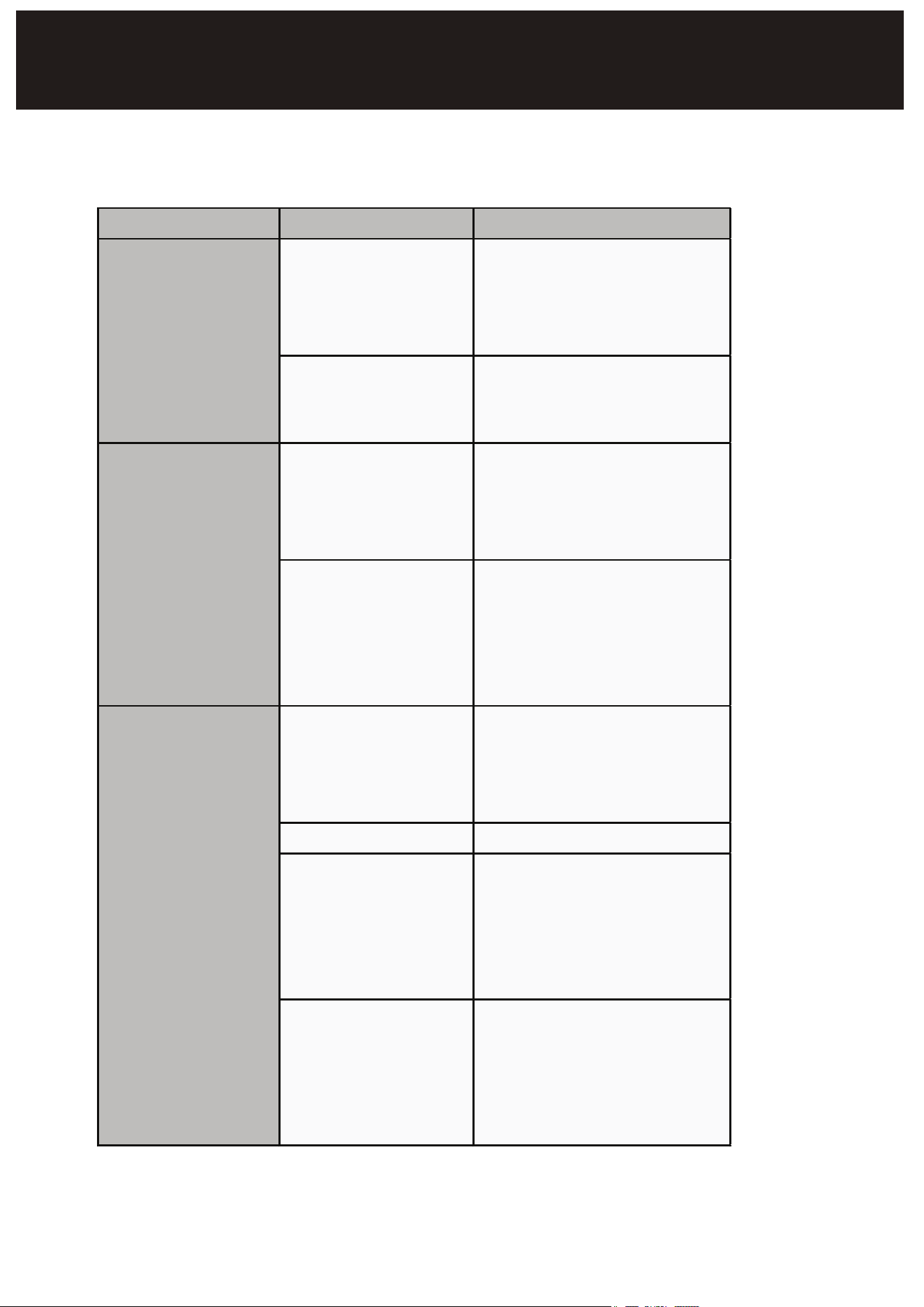
TROUBLESHOOTING
Symptoms Causes Solutions
Burners won’t
light
- Gas supply off -
Air in lines
- Check main/unit gas
valves - Turn gas valve on.
Attempt to light pilot every
15 sec.
- Pilot valve not lit
- Turn off gas - allow unit
to vent for 5 minutes. Turn
gas back on and light pilot
Front or rear
burner won’t light
- Control not on -
Water in burner
- Turn temperature control
to ON. Set to desired
setting when lit - Remove
burner and dry thoroughly
- Damaged
temperature control,
Burner, or other
internal component
- Contact manufacturer for
repairs
Pilot will not light
- Gas supply off -
Air in lines
- Check main/unit gas
valves - Turn pilot valve on.
Attempt to light pilot every
15 sec.
- Pilot valve not on - Turn pilot valve on/adjust
- Burner not hot
enough -
Temperature control
not set
- Adjust for desired
temperature - Shutter or
nozzle out of adjustment -
Contact qualified technician
for adjustment
- Damaged
temperature control,
burner, or other
internal component
- Contact manufacturer for
repairs

LIMITED WARRANTY
Koolmore Supply, Inc. extends a limited warranty to the original purchaser, guaranteeing that this Koolmore
product is free from manufacturing defects in material or workmanship for one year from the date of
purchase.
Should you discover any such defect within the warranty period, Koolmore Supply, Inc., reserves the right to
repair or replace the product without charge, or to cover the cost of replacement parts and repair labor needed
to correct defects present at the time of purchase or resulting from regular usage, when the appliance has been
installed, operated, and maintained as per the instructions provided.
At its sole discretion, Koolmore Supply Inc. may decide to replace the product. In such an event, your replace-
ment appliance will carry the warranty for the remaining term of the original unit's warranty period.
This warranty is valid exclusively to the original purchaser of the product and only applicable within the United
States. The warranty commences from the date of original consumer purchase. Proof of the original purchase
date will be required to obtain service under this warranty.
Under this limited warranty, your sole and exclusive remedy will be product repair, as outlined above. All
services must be provided by a Koolmore-designated service company.
To claim warranty or request repair service:
Email suppor[email protected]. Please include your name, address, phone number, warranty repair request,
and a copy of your proof of purchase receipt. Alternatively, visit koolmore.com and use the contact us page. A
Koolmore customer service representative will promptly arrange service for your appliance.
We thank you for choosing Koolmore.
WARRANTY EXCLUSIONS
This limited warranty will not cover:
1. Failure of the product to perform during power failures or interruptions,
or due to inadequate electrical service.
2. Damage incurred during transportation or handling.
3. Damage caused by accidents, vermin, lightning, winds, fire, floods, or acts of God.
4. Damage resulting from accidents, alterations, misuse, abuse, improper installation, repair, or mainte-
nance. This includes using any external device that alters or converts the voltage or frequency of
electricity.
5. Unauthorized product modifications, repairs by unauthorized centers, or use of non-approved
replacement parts.
6. Abnormal cleaning and maintenance not aligned with the user's manual.
7. Use of incompatible accessories or components.
8. Any costs associated with repairs or replacements under these excluded circumstances shall be the
responsibility of the consumer.
WARRANTY