Ice-O-MaticPage 1
Installation Guide and Owner’s Manual
Original Instructions
BEFORE PROCEEDING, VERIFY YOUR PRODUCT’S REFRIGERANT TYPE
• Refrigerant type is designated on the product’s Serial Nameplate
• Refrigerant type is designated on the product’s Specification Sheet
• Refrigerant type can be determined from the model number. The last two digits preceding the hyphen indicate the refrigerant type. For example,
model RC306C40 contains refrigerant R-404A as indicated by the “40”. Model numbers containing “49” preceding the hyphen contain refrigerant
R-449A.
TABLE OF CONTENTS
REMOTE CONDENSER SAFETY ......................................................................................................................................................................................... 2
MODEL NOMENCLATURE .................................................................................................................................................................................................... 2
CONFIGURATIONS ............................................................................................................................................................................................................... 3
CONDENSER DIMENSIONS ................................................................................................................................................................................................. 3
EQUIPMENT RATINGS ......................................................................................................................................................................................................... 4
INSTALLATION INSTRUCTIONS .......................................................................................................................................................................................... 4
OPERATION ........................................................................................................................................................................................................................... 7
SERVICE ................................................................................................................................................................................................................................ 7
DISPOSAL .............................................................................................................................................................................................................................. 7
WARRANTY AND SERVICE PROVIDERS ............................................................................................................................................................................ 7
CONTACT .............................................................................................................................................................................................................................. 7
WARNING
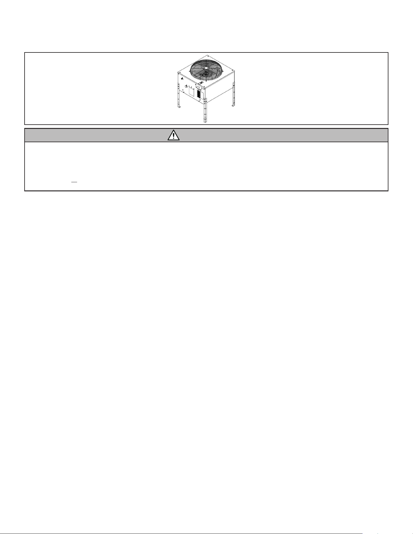
REMOTE CONDENSER
RC MODEL SERIES
9081543-01 Rev B
Ice-O-Matic Page 2
9081543-01 Rev B
REMOTE CONDENSER SAFETY
Your safety and the safety of others are very important.
Many important safety messages have been provided in this manual and on the appliance. Always read and obey all safety messages.
This is the safety alert symbol.
This symbol alerts you to potential hazards that can kill or hurt you and others.
Safety messages will follow the safety alert symbol and either the word “DANGER” OR “WARNING”. These words mean:
DANGER
Indicates death or serious injury will result if proper precautions are not taken.
WARNING
Indicates death, serious injury, or property damage can result if proper precautions are not taken.
This is the Risk of Fire / Flammable Materials symbol.
This symbol alerts you to the presence of ammable materials.
When this symbol appears in this manual or on the ice maker, care should be taken to avoid causing a re by igniting ammable material.
This is the Potable Water symbol.
This symbol indicates that connection to potable drinking water supply is required.
DANGER
Please read these instructions completely before starting the installation or performing any service. Failure to follow the instructions and safety
precautions in this manual can result in serious injury or death. Manufacturer assumes no responsibility for improperly installed equipment.
IMPORTANT SAFETY INSTRUCTIONS
WARNING: To reduce the risk of re, electric shock, or injury to persons when using the ice maker, follow basic precautions, including the following:
• Product shall not be installed in locations accessible to children. Children should be supervised to ensure that they do not play with the appliance.
• This appliance is not intended for use by persons (including children) with reduced physical, sensory, or mental capabilities, or lack of experience
and knowledge, unless they have been given supervision or instruction concerning the use of the appliance by a person responsible for their safety.
• Do not store explosive substances such as aerosol cans with a ammable propellant in this appliance.
• This appliance is not to be used at altitudes exceeding 14,000 ft [4,267 m].
• WARNING: Product shall only be connected to an appliance suitable for the same refrigerant.
SAVE THESE INSTRUCTIONS
FREIGHT CLAIMS
INSPECT PROMPTLY: This merchandise has been carefully inspected an packed in accordance with the carrier’s packing specications. Responsibility
for safe delivery has been assumed by the carrier. If loss or damage occurs, you as the consignee must le a claim with the carrier and hold the
container for carrier’s inspection.
VISIBLE LOSS OR DAMAGE: Any external evidence of loss or damage must be fully described and noted on the freight bill or express receipt and
signed by the carrier’s agent. The claim should be led on a form available from the carrier.
CONCEALED LOSS OR DAMAGE: If loss or damage does not appear until merchandise has been unpacked, make a written request for inspection by
the carrier within ve days of delivery date, then le a claim on a form from the carrier.
FILE CLAIMS WITHOUT DELAY—DO NOT RETURN DAMAGED GOODS TO MANUFACTURER
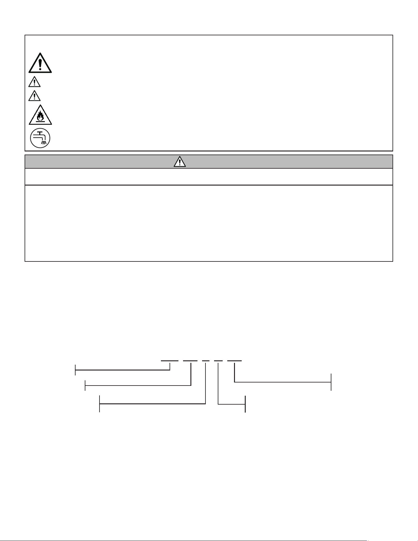
MODEL NOMENCLATURE
RC 10 0 C 49
Model Series
Remote Condenser
Approximate Capacity
Btu/hr x 1000
Electrical Designator
0 = 115V / 50Hz or 60Hz
6 = 208-230V / 50Hz or 60Hz
Refrigerant Designator
40 = R404A
49 = R449A
Model Type
C = For Cuber Type Ice Maker (with Headmaster)
G = For Flake/Nugget Type Ice Maker (without Headmaster)
Ice-O-MaticPage 3
CONFIGURATIONS
RC Model Compatible Ice Maker Models
RC100C49 CIM0530(+)R49
RC100G49 GEM0650R49; MFI0800R49
RC106C49 CIM0636(+)R49
RC106G49
GEM0956R49; MFI1256R49; GEM1306R49,
MFI1506R49
RC206C49
CIM0826(+)R49; CIM0836(+)R49; CIM1126(+)R49;
CIM1136(+)R49
RC306C49
CIM1446(+)R49; ICE1506(+)R49;
GEM2006R49; MFI2306R49
RC406C49 CIM2046(+)R49
R-449A Models
Where (+) is F, H, or G
R-404A Models
RC Model Compatible Ice Maker Models
RC100C40 CIM0530(+)R
RC100G40 GEM0650R; MFI0800R
RC106C40 CIM0636(+)R
RC106G40 GEM0956R; MFI1256R; GEM1306R, MFI1506R
RC206C40
CIM0826(+)R; CIM0836(+)R; CIM1126(+)R;
CIM1136(+)R
RC306C40 CIM1446(+)R; ICE1506(+)R;
GEM2006R; MFI2306R
RC406C40 CIM2046(+)R
Where (+) is F, H, or G
Remote Line Sets and Accessories
Part Number Description
RL49-25 Pre-charged R-449A, 25 ft [7.6 m] Line Set
RL49-40 Pre-charged R-449A, 40 ft [12.2 m] Line Set
RL49-75 Pre-charged R-449A, 75 ft [22.9 m] Line Set
RL404-25 Pre-charged R-404A, 25 ft [7.6 m] Line Set
RL404-40 Pre-charged R-404A, 40 ft [12.2 m] Line Set
RL404-75 Pre-charged R-404A, 75 ft [22.9 m] Line Set
KRL-25 Kit, non-charged, 25 ft [7.6 m] Line Set
KRL-40 Kit, non-charged, 40 ft [12.2 m] Line Set
KRL-75 Kit, non-charged, 75 ft [22.9 m] Line Set
1051255-01 Kit, quick connect couplings only: Qty (2) 3/8”
and Qty (2) 1/2” Couplings
WARNING: The Ice Maker, Remote Condenser, and Remote Line Set
must all utilize the same refrigerant. Failure to do so will result in product
damage.
REFRIGERANT CHARGE
All remote condenser models are pre-charged with 16 oz [454 g] of
either R-449A or R-404A refrigerant. Pre-charged line sets contain 4 oz
[113 g] of either R-449A or R-404A refrigerant. Refer to Ice Maker
serial nameplate for required total system charge.
9081543-01 Rev B
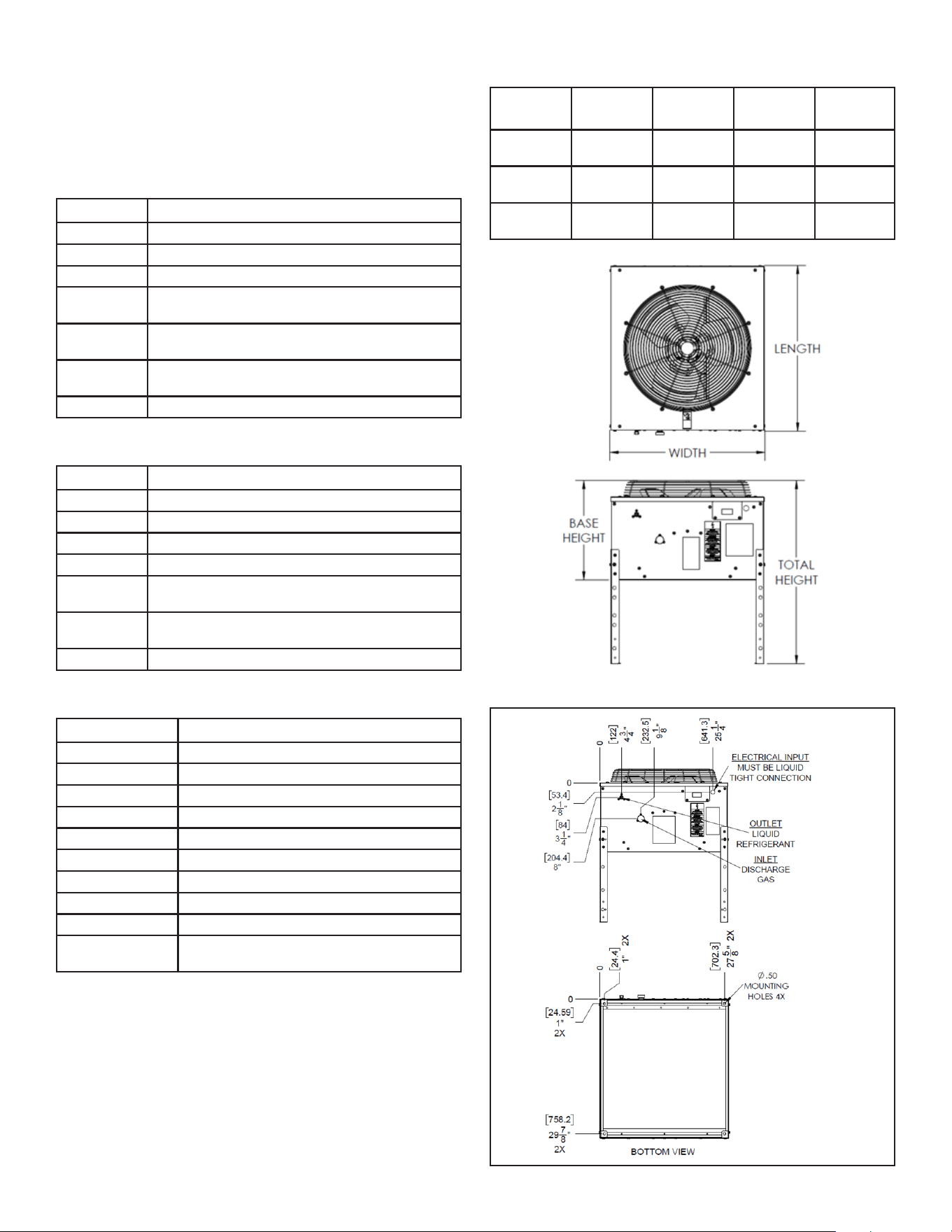
CONDENSER DIMENSIONS
RC
Model
Width Length Base
Height
Total
Height
RC10*
RC20*
28.9 in
[734 mm]
31.1 in
[791 mm]
18.7 in
[474 mm]
34.1 in
[874 mm]
RC30* 30.9 in
[784 mm]
34.6 in
[879 mm]
19.2 in
[487 mm]
34.9 in
[887 mm]
RC40* 30.9 in
[784 mm]
34.6 in
[879 mm]
23.2 in
[588 mm]
38.9 in
[988 mm]
* Followed by additional letters and numbers
MODELS RC10*, RC20*
Dimensions in inches [mm]
* Followed by additional
letters and numbers
IMPORTANT: The RC Series remote condensers may only be used with
compatible Ice-O-Matic® ice makers. All rack-type condenser systems
must receive written approval from manufacturer.
Ice-O-Matic Page 4
9081543-01 Rev B
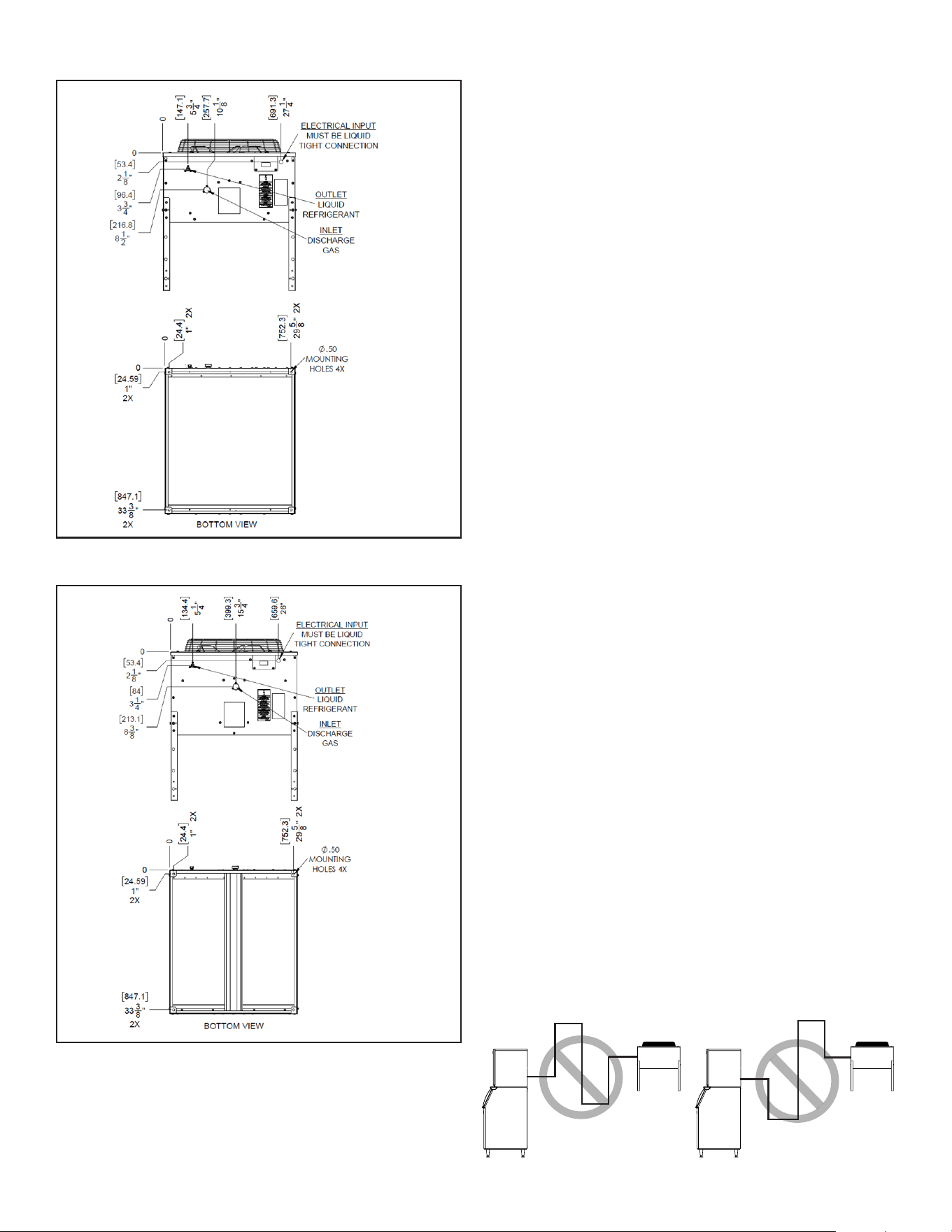
MODELS RC30*
Dimensions in inches [mm]
* Followed by additional
letters and numbers
MODELS RC40*
Dimensions in inches [mm]
* Followed by additional
letters and numbers
EQUIPMENT RATINGS
• Ambient Air Temperature: -20 to 120 °F [-28.9 to 48.9 °C]
• Approved for Outdoor Installation
• R-449A GWP (AR5): 1282
• R-449A ASHRAE Safety Classication: A1
• R-404A GWP (AR5): 3943
• R-404A ASHRAE Safety Classication: A1
INSTALLATION INSTRUCTIONS
Overview
Remote condenser systems are comprised of three components: the
pre-charged remote condenser, the pre-charged ice maker, and the
pre-charged line set. For installation of the ice making head, reference
the installation instructions supplied with the ice maker.
Select a Location
The proper selection of a location for the remote condenser is critical to
the performance and longevity of the ice-making system. Please follow
these guidelines when choosing a location for your remote condenser:
• This product shall not be installed within 20 ft [6.1 m] of any building
opening. If this product is enclosed within a penthouse, lean-to,
or other open structure, natural or mechanical ventilation shall be
provided. Refrigerant circuit access ports located outdoors shall be
secured to prevent unauthorized access.
• The remote condenser shall not be used in areas where sucient
airow is not available. It shall not be installed in the same area where
the ice maker is installed.
• Choose a location which is protected from extremes of dirt, dust, rain,
hail, sun, and prevailing winds.
• Consider the eect of the heat being rejected into the condenser
installation area and ensure this additional heat is acceptable.
• Vertical air discharge requires at least 48 inches [1.2 m] clearance
above the condenser.
• Condenser must have a minimum clearance of 18 inches [457 mm] on
three sides. One side must be open for proper ventilation.
• Install condenser with included legs. Condenser must have a minimum
clearance of 15 inches [381 mm] between the mounting surface and
the condenser base.
• Condenser must be installed on a level surface.
• Condenser location higher than the ice maker is preferred.
• Installation location may be aected by local building codes. Be sure to
follow all applicable local, state, and national building, plumbing, and
electrical codes.
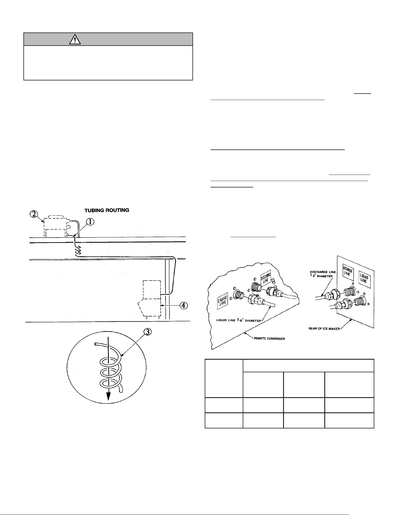
Location Rise and Run Limits
Use the following information for planning the placement of the remote
condenser relative to the ice machine.
The remote condenser location must not exceed ANY of the following.
Congurations that do not meet these requirements must receive written
authorization from the manufacturer.
• Maximum rise from the ice machine to the remote condenser: 35
physical feet [10.67 physical meters]
• Maximum drop from the ice machine to the remote condenser: 10
physical feet [3.05 physical meters]
• Maximum line set length: 75 physical feet [22.86 physical meters]
• Maximum calculated line set length: 100 feet [30.48 m]
Determine the calculated line set length using the formulas below:
Calculated line set length = Drop + Rise + Horizontal Run
Drop = dd x 6.6 where dd = drop distance in ft or m
Rise = rd x 1.7 where rd = rise distance in ft or m
Horizontal Run = horizontal distance in ft or m
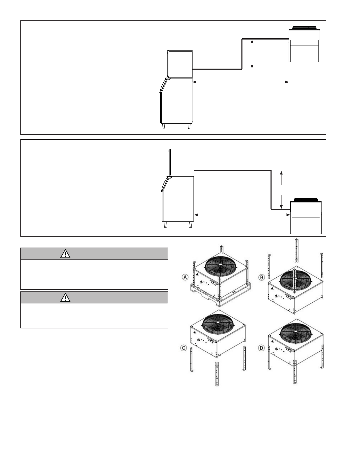
IMPORTANT: Do not route a line set that rises, then falls, then rises. Do
not route a line set that falls, then rises, then falls. See diagram below.
Ice-O-MaticPage 5
34 ft Horizontal
10 ft Drop
40 ft Horizontal
35 ft Rise
Equivalent Run Calculation Example: Rise
Calculated line set length = (Rise x 1.7) + (Drop x 6.6) + Horizontal Run
Calculated line set length = (35 x 1.7) + (0 x 6.6) + 40
Calculated line set length = 99.5 ft
Calculated line set length must not exceed 100 ft
Equivalent Run Calculation Example: Drop
Calculated line set length = (Rise x 1.7) + (Drop x 6.6) + Horizontal Run
Calculated line set length = (0 x 1.7) + (10 x 6.6) + 34
Calculated line set length = 100 ft
Calculated line set length must not exceed 100 ft
Unpack the Remote Condenser
WARNING
Excessive Weight Hazard
Use two or more people to move and install or uninstall the appli-
ance.
Failure to do so can result in back or other injury.
Remove the Packaging
• Remove the cardboard box from the remote condenser.
• Lift the remote condenser o the pallet.
WARNING
Sharp Edges Hazard
Wear cut resistant gloves when handling appliance.
Failure to do so can result in lacerations or other injury.
Condenser legs are secured to the appliance in a shipping conguration.
Perform the following steps to prepare the unit for installation:
• Remove (3) screws from each leg to remove it from the condenser
assembly. Save the screws.
• Flip the leg assembly as shown
• Secure the leg to the condenser assembly using the previously
removed screws
Remove and Install Condenser Legs
Secure to Mounting Surface
Secure the remote condenser to its mounting surface using the methods
and practices appropriate for the mounting surface. Each leg is provided
with a 0.50 in [12.7 mm] mounting hole. If attaching to a roof, use a
qualied roong technician to perform mounting to prevent leaks and
other roof damage. Attachment method shall conform to all applicable
building codes.
9081543-01 Rev B
Ice-O-Matic Page 6
9081543-01 Rev B
Plan Refrigerant Tubing Route
Plan the route of the refrigeration tubing between the ice maker and the
remote condenser. Follow these guidelines to ensure proper performance
and longevity of the ice making system:
• IMPORTANT: Excess tubing shall be coiled inside the building in a
vertical spiral as shown below.
• All tubing routed outdoors shall be insulated to protect against external
ambient conditions.
• Tubing should follow straight line routing whenever possible.
• The lowest location in the tubing run should be the connection at the
rear of the ice maker.
Make Roof/Wall Openings for Tubing
Make openings in walls and/or roof as needed to route refrigerant tubing
through. Hole size shall be minimum 1.75 inch [44.5 mm] diameter.
Route Refrigerant Tubing
WARNING
Pre-charged Line Sets Under Pressure
Wear eye protection when handling pre-charged line sets.
Failure to do so can result in eye or other injury.
Each set of pre-charged refrigerant line sets consists of a 3/8 inch
diameter liquid line and a 1/2 inch diameter discharge line. Both ends
of the refrigerant lines have quick connect couplings and Schrader valve
service connections.
WARNING: When handling pre-charged refrigerant line sets, extreme
care should be taken to ensure tubing is not kinked or cracked. Kinked
tubing can result in a poorly performing ice making system. A cracked
tube will require repair by a qualied refrigeration technician.
Route Refrigerant Tubing
• Route refrigerant tubing as planned, following guidelines above
• Have a qualied technician seal holes in walls/roof following all
applicable building codes
Note: Do not connect the pre-charged tubing until all routing and forming
of the tubing is complete. Failure to do so may result in equipment
damage.
Make Refrigerant Tubing Connections to Remote
Condenser and Ice Maker
The couplings supplied with pre-charged line sets are self-sealing
when installed properly. To ensure a leak-free installation, follow these
instructions carefully.
• Preparation: Remove caps and plugs from the couplings when ready
to connect. Check the threads and seals for damage. Wipe away any
foreign material from the coupling threads and sealing surfaces with a
clean cloth.
• Lubricate: Apply POE (polyol ester) refrigerant oil to the surfaces of
the diaphragms, o-rings, and threaded areas of the couplings. Failure
to apply lubricant can result in damage and leaks. POE oil is included
with line sets and line set kits. Use a small applicator brush and
liberally apply lubricant.
• Hand Tighten: Ensure that the coupling halves are held in proper
alignment with each other prior to starting the threads. The coupling
end faces should be parallel with each other and visually in-line.
Tighten by hand for the initial 2-3 rotations of the swivel nut. If it is too
dicult to get started by hand, repositions the nut for proper alignment.
Do not force the connection as cross-threading may occur.
• Wrench Tighten: Using two appropriate sized wrenches (see table
below), tighten the swivel nut while preventing rotation of the coupling
body. As the swivel nut is tightened, the diaphragms will start to be
pierced and there will be an increase in resistance. Important: Do not
let the coupling bodies rotate during any portion of the installation or
damage will occur. Continue to tighten the swivel nut until there is a
denite increase in resistance and metal-to-metal contact occurs. At
this point, the swivel nut will have covered most of the threads.
• Final Tighten: A nal 1/4 turn (90° rotation) is necessary to ensure
the formation of a leak-free sealed connection between the couplings.
Using a marker or scribe, mark a line lengthwise from the coupling
swivel nut to either the bulkhead or coupling body. Then tighten an
additional 1/4 turn (90° rotation), using the marking on the swivel nut to
conrm. Do not over tighten.
• Leak Check: Once all connections have been made, check each
connection for leaks.
Coupling
Size
Required Wrench Size
Female
Coupling
Body
Female
Coupling
Swivel Nut
Torque
min-max
3/8 inch 5/8 inch 13/16 inch 10-12 ft-lb
[13.6 - 16.3 Nm]
1/2 inch 1 inch 1-5/16 inch 35-45 ft-lb
[47.5 - 61.0 Nm]
Ice-O-MaticPage 7
WARNING
Electrical Shock Hazard
Electrical connection must be made by authorized service
personnel.
Failure to do so can result in death, re, or electrical shock.
The ice maker and the remote condenser both require a solid earth
ground that meets all applicable codes. The remote condenser is
designed to be wired to and powered by the ice maker.
IMPORTANT: A means for disconnection from the supply mains must be
incorporated in the xed wiring in accordance with the wiring rules.
Make Electrical Connections to Remote Condenser
Please follow these instructions carefully to make electrical connections
to the remote condenser:
• Determine appropriate wire size for electrical connection. Reference
the serial data plate on the condenser for the appliance’s Minimum
Circuit Ampacity (MCA).
• Ensure the supply voltage is the same as the rated voltage shown on
the serial data plate on the condenser
• Route wire through building following all applicable codes and
standards.
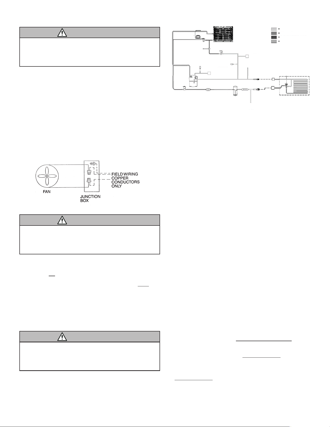
• Make connections to condenser according to the diagram below.
Make Electrical Connections
Make Electrical Connections to Ice Maker
WARNING
Electrical Shock Hazard
Ensure power to the Ice Maker has been turned o.
Failure to do so can result in death, re, or electrical shock.
IMPORTANT: Ensure power to the ice maker has been turned o before
proceeding.
Make electrical connections to ice maker by following these steps:
• Connect the red wire leads from the ice maker to the positive and
negative eld wire leads connected to the remote condenser
• Secure the ground lead from the eld wires underneath the green
grounding screw located in the ice maker eld wiring junction box
• Secure the junction box cover to the junction box when complete.
OPERATION
Reference the installation instructions for the ice making head which is
being installed with the remote condenser for operation instructions.
SERVICE
WARNING
Electrical Shock Hazard
Disconnect electrical supply from machine prior to performing
any adjustments or repairs.
Failure to do so can result in death, re, or electrical shock.
IMPORTANT: For proper and safe servicing, please read these
instructions completely. All service work must be performed by authorized
service personnel.
See the following Remote Condenser Refrigeration System Diagram and
the component descriptions.
Head Pressure Control Valve: The head pressure control valve (also
known as the Headmaster, Mixing Valve, or Low Ambient Control Valve)
serves as the head pressure regulating valve. When the temperature
of the condenser is above 70 °F [21 °C], the refrigerant ow from the
compressor is directed by the mixing valve through the condenser and
into the receiver. When the temperature at the condenser drops below
70 °F [21 °C], the pressure in the bellows of the mixing valve becomes
greater than the pressure of the liquid refrigerant in the condenser. This
change allows the valve to partially restrict the ow of refrigerant leaving
the condenser and allows discharge gas to bypass the condenser and
ow directly into the receiver, mixing with the liquid refrigerant from the
condenser. The amount of discharge gas that bypasses the condenser
increases as the ambient temperature decreases. This action of the
mixing valve allows the discharge pressure to be properly maintained
during low ambient conditions: for cube ice makers, discharge pressure is
maintained at approximately 210-240 psig [1.45-1.66 MPa]; for nugget/
flake ice makers, 170-200 psig [1.17-1.38 MPa]. If the refrigerant system
is undercharged and the ambient temperature is below 70 °F [21 °C], the
mixing valve will not work properly and allow too much refrigerant to
bypass the condenser.
Receiver: Stores liquid refrigerant discharged from the condenser. The
quantity of liquid refrigerant in the receiver will vary with the temperature
at the condenser coil.
Liquid Line Solenoid: Controls the flow of liquid refrigerant from the
receiver to the thermal expansion valve (TXV).
Pump Down Control: Low-pressure switch that has a opening pressure
of approximately 5-10 psig [34.4-68.9 kPa] that controls the contactor to
shut the compressor off during pumpdown. The low-pressure switch
resets (contacts close) when the low side pressure rises to approximately
25-35 psig [172.4-241.3 kPa].
Condenser Fan Motor: The condenser fan motor is a single speed and
should be wired according to the wiring diagram. The motor is
permanently lubricated for long-life.
DISPOSAL
IMPORTANT: This appliance contains refrigerant and must be disposed
of in accordance with applicable national, state, and local codes and
regulations. Refrigerant must be recovered by properly certified service
personnel.
ICE-O-MATIC WARRANTY
Every Ice-O-Matic ice maker is backed by a warranty that provides both
parts and labor coverage. To view the warranty details, register products,
or check your warranty status visit www.iceomatic.com/warranty.
FINDING A SERVICE PROVIDER
To find a service provider, please visit www.iceomatic.com
CONTACT US
For warranty service, call 1-855-832-4466, or visit our website
at www.iceomatic.com.
Mile High Equipment, LLC
11100 E 45th Ave
Denver, CO 80239
United States of America
Evaporator Coil
Valve (TXV)
High Temp
Switch
Hot Gas Valve
High Pressure
Control
Pumpdown
Control
Compressor
Service Port
Service Port
Process
Port
Liquid Line
Solenoid
Drier
Receiver
Tank
Check
Valve
Process
Port
Head Pressure
Control Valve
Remote
Condenser
High Pressure Gas
High Pressure Liquid
Low Pressure Liquid
Low Pressure Gas
9081543-01 Rev B