
No. 1405 99500-44050-01E LT-F500F S/M August, 09, 2002
No. 1405 99500-44050-01E LT-F500F S/M August, 09, 2002
GROUP INDEX
GENERAL INFORMATION
1
PERIODIC MAINTENANCE
2
ENGINE
3
DRIVE TRAIN
4
FUEL SYSTEM
5
COOLING AND LUBRICATION
SYSTEM
6
CHASSIS
7
ELECTRICAL SYSTEM
8
SERVICING INFORMATION
9
FOREWORD
This manual contains an introductory description on
the SUZUKI LT-F500F and procedures for its
inspection, service, and overhaul of its main compo-
nents.
Other information considered as generally known is
not included.
Read the GENERAL INFORMATION section to
familiarize yourself with the vehicle and its mainte-
nance. Use this section as well as other sections as
a guide for proper inspection and service.
This manual will help you know the vehicle better so
that you can assure your customers of fast and reli-
able service.
!
© COPYRIGHT SUZUKI MOTOR CORPORATION 2002
* This manual has been prepared on the basis
of the latest specifications at the time of publi-
cation. If modifications have been made since
then, differences may exist between the con-
tent of this manual and the actual vehicle.
* Illustrations in this manual are used to show
the basic principles of operation and work
procedures. They may not represent the
actual vehicle exactly in detail.
* This manual is written for persons who have
enough knowledge, skills and tools, including
special tools, for servicing SUZUKI vehicles.
If you do not have the proper knowledge and
tools, ask your authorized SUZUKI motorcy-
cle dealer to help you.
Inexperienced mechanics or mechanics
without the proper tools and equipment
may not be able to properly perform the
services described in this manual.
Improper repair may result in injury to the
mechanic and may render the vehicle
unsafe for the rider.
HOW TO USE THIS MANUAL
TO LOCATE WHAT YOU ARE LOOKING FOR:
1. The text of this manual is divided into sections.
2. The section titles are listed in the GROUP INDEX.
3. Holding the manual as shown at the right will allow you to find
the first page of the section easily.
4. The contents are listed on the first page of each section to
help you find the item and page you need.
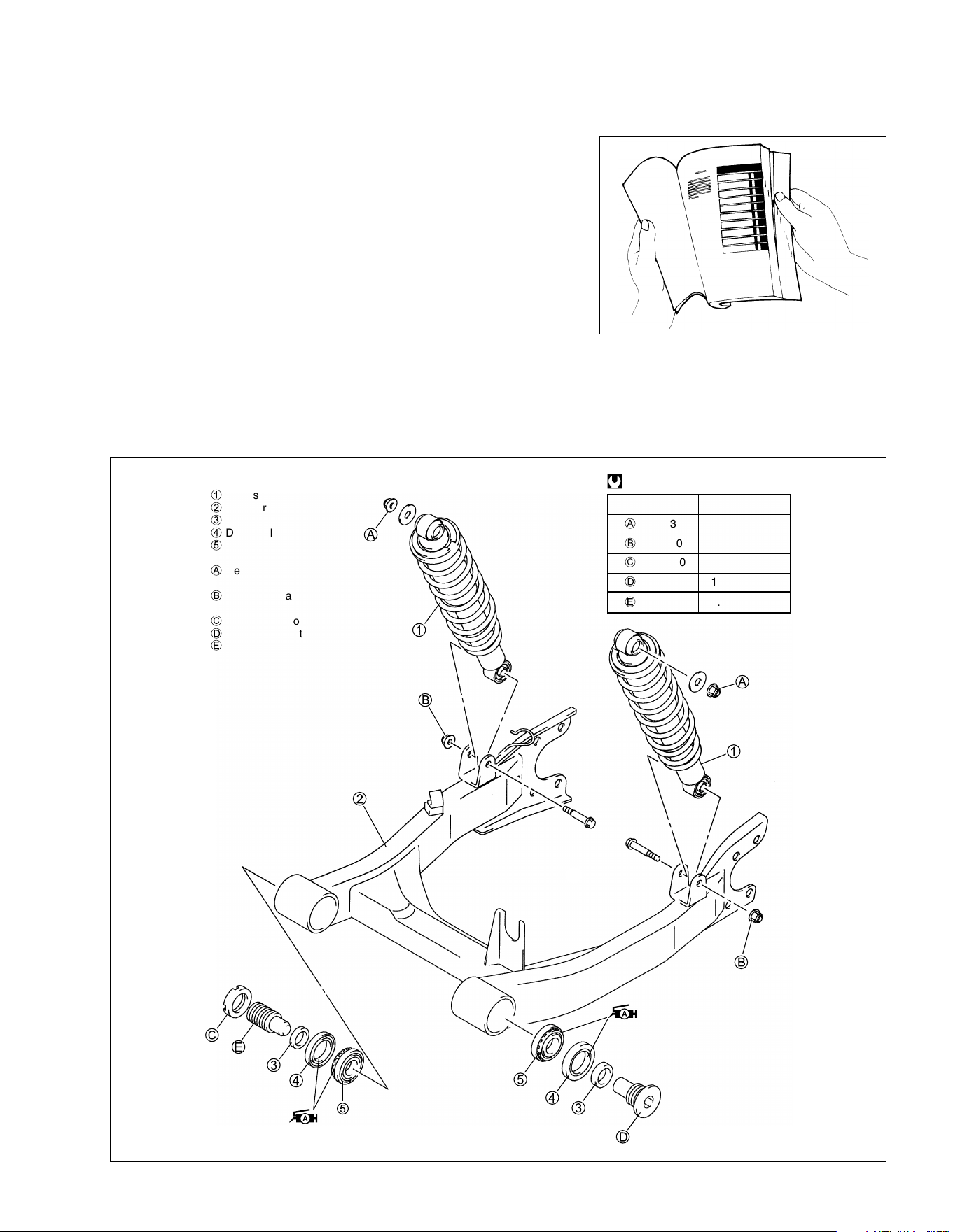
COMPONENT PARTS AND WORK TO BE DONE
Under the name of each system or unit there is an exploded view which provides work instructions and other
service information (e.g.; tightening torque, lubricating points, and locking agent points).
Example: Rear suspension
ITEM N·m kgf
-
m lb-ft
A
35 3.5 25.5
B
60 6.0 43.5
C
100 10.0 72.5
D
100 10.0 72.5
E
9.5 0.95 7.0
@
1
Rear shock absorber
2
Swingarm
3
Spacer
4
Dust seal
5
Bearing
A
Rear shock absorber mounting
upper nut
B
Rear shock absorber mounting
lower nut
C
Swingarm pivot locknut
D
Swingarm pivot bolt (LH)
E
Swingarm pivot bolt (RH)
SYMBOL
Listed in the table below are the symbols indicating instructions and other information necessary for servic-
ing. The meaning of each symbol is also included in the table.
SYMBOL DEFINITION SYMBOL DEFINITION
Torque control required.
Data beside it indicates specified
torque.
Apply THREAD LOCK SUPER “1303”.
99000-32030
Indicates service data. Apply THREAD LOCK SUPER “1322”.
99000-32110 (Except USA)
Apply oil. Use engine oil unless
otherwise specified.
Apply THREAD LOCK “1342”.
99000-32050
Apply hypoid gear oil. Apply THREAD LOCK SUPER “1360”.
99000-32130
Apply molybdenum oil solution.
(mixture of engine oil and SUZUKl
MOLY PASTE in a ratio of 1 : 1)
Apply or use brake fluid.
Apply SUZUKI SUPER GREASE “A”.
99000-25030 (USA)
99000-25010 (Others)
Measure in voltage range.
Apply SUZUKI SILICONE GREASE.
99000-25100
Measure in resistance range.
Apply SUZUKI MOLY PASTE.
99000-25140
Measure in current range.
Apply WATER RESISTANCE GREASE.
99000-25160
Measure in diode test range.
Apply SUZUKI BOND “1207B”
99104-31140 (USA)
Measure in continuity test range.
Apply SUZUKI BOND “1215”.
99000-31110 (Except USA)
Use special tool.
Apply SUZUKI BOND “1216B”.
99100-31230
Use engine coolant.
99000-99032-11X (Except USA)
H/O
W
1216B

1
GENERAL INFORMATION 1-1
CONTENTS
GENERAL INFORMATION
WARNING/CAUTION/NOTE ..............................................................1- 2
GENERAL PRECAUTIONS ................................................................1- 2
SUZUKI LT-F500FK3 (2003-MODEL) ................................................1- 4
SERIAL NUMBER LOCATION ...........................................................1- 4
FUEL, OIL AND ENGINE COOLANT RECOMMENDATION ............1- 4
FUEL ............................................................................................1- 4
ENGINE OIL..................................................................................1- 5
FRONT AND REAR DRIVE GEAR OIL .......................................1- 5
BRAKE FLUID .............................................................................1- 5
ENGINE COOLANT .....................................................................1- 5
BREAK-lN PROCEDURES ................................................................1- 6
INFORMATION LABELS ....................................................................1- 7
SPECIFICATIONS ..............................................................................1- 8
COUNTRY AND AREA CODES .........................................................1-10

1-2 GENERAL INFORMATION
WARNING/CAUTION/NOTE
Please read this manual and follow its instructions carefully. To emphasize special information, the symbol
and the words WARNING, CAUTION and NOTE have special meanings. Pay special attention to the mes-
sages highlighted by these signal words.
!
Indicates a potential hazard that could result in death or injury.
"
Indicates a potential hazard that could result in vehicle damage.
NOTE:
Indicates special information to make maintenance easier or instructions clearer.
Please note, however, that the warnings and cautions contained in this manual cannot possibly cover all
potential hazards relating to the servicing, or lack of servicing, of the vehicle. In addition to the WARNINGS
and CAUTIONS stated, you must use good judgement and basic mechanical safety principles. If you are
unsure about how to perform a particular service operation, ask a more experienced mechanic for advice.
GENERAL PRECAUTIONS
!
* Proper service and repair procedures are important for the safety of the service mechanic and
the safety and reliability of the vehicle.
* When two or more persons work together, pay attention to the safety of each other.
* When it is necessary to run the engine indoors, make sure that exhaust gas is forced out-
doors.
* When working with toxic or flammable materials, make sure that the area you work in is well
ventilated and that you follow all of the manufacturer’s instructions.
* Never use gasoline as a cleaning solvent.
* To avoid getting burned, do not touch the engine, engine oil, radiator, and exhaust system
until they have cooled.
* After servicing the fuel, oil, engine coolant, exhaust or brake systems, check all of the lines,
and fittings related to the system for leaks.

GENERAL INFORMATION 1-3
"
* If parts replacement is necessary, replace the parts with SUZUKI Genuine Parts or their equiv-
alent.
* When removing parts that are to be reused, keep them arranged in an orderly manner so that
they may be reinstalled in the proper order.
* Be sure to use special tools when instructed.
* Make sure that all parts used in reassembly are clean. Lubricate them when specified.
* Use the specified lubricants, bonds, or sealants.
* When removing the battery, disconnect the
- battery lead wire first, then the
+ battery lead
wire.
* When reconnecting the battery, connect the
+ battery lead wire first, then the
- battery lead
wire. Finally, cover the
+ battery terminal with the terminal cover.
* When performing service to electrical parts, disconnect the
- battery lead wire, unless the
service procedure requires the battery power.
* When tightening cylinder head and crankcase nuts and bolts, tighten the larger sizes first.
Always tighten the nuts and bolts from the inside working out, diagnoally and to the specified
torque.
* Whenever you remove oil seals, gaskets, packing, O-rings, self-locking nuts, locking wash-
ers, cotter pins, circlips, snap rings, and other specified parts, be sure to replace them with
new ones. Also, before installing these new parts, be sure to remove any left over material
from the mating surfaces.
* Never reuse a circlip and snap ring. When installing a new snap ring, take care not to expand
the end gap larger than required to slip the snap ring over the shaft. After installing a snap
ring, always ensure it is completely seated in its groove and securely fitted.
* Use a torque wrench to tighten fasteners to the specified torque. Wipe off grease and oil if a
thread is smeared with them.
* After reassembling, check parts for tightness and proper operation.
* To protect the environment, do not unlawfully dispose of used motor oil, engine coolant, all
other fluids, batteries, and tires.
* To protect the earth’s natural resources, properly dispose of used vehicles and parts.
1-4 GENERAL INFORMATION
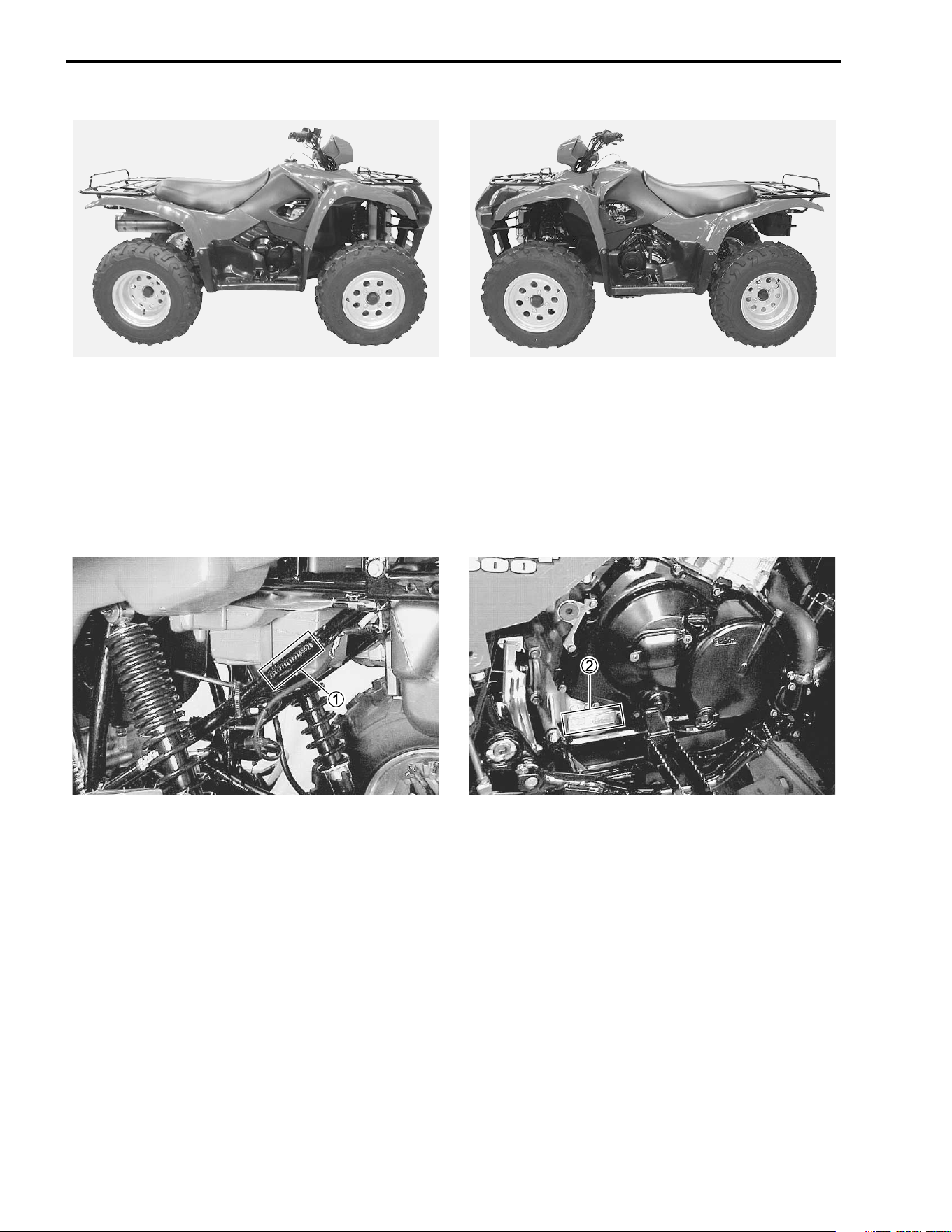
SUZUKI LT-F500FK3 (2003-MODEL)
* Difference between photographs and actual vehicles depends on the markets.
SERIAL NUMBER LOCATION
The frame serial number or V.I.N. (Vehicle Identification Number)
1 is stamped on the left side of the rear
frame pipe. The engine serial number
2 is located on the right side of the crankcase. These numbers are
required especially for registering the machine and ordering spare parts.
FUEL, OIL AND ENGINE COOLANT RECOMMENDATION
FUEL (For CANADA and USA)
• Use only unleaded gasoline of at least 87 pump octane ( ) method or 91 octane or higher rated by
the Research Method.
• SUZUKI recommends that customers use alcohol-free unleaded gasoline whenever possible.
• Use of blended gasoline containing MTBE (Methyl Tertiary Butyl Ether) is permitted.
• Use of blended gasoline/alcohol fuel is permitted, provided that the fuel contains not more than 10% etha-
nol. Gasoline/alcohol fuel may contain up to 5% methanol if appropriate cosolvents and corrosion inhibi-
tors are present in it.
• If the performance of the vehicle is unsatisfactory while using blended gasoline/alcohol fuel, you should
switch to alcohol-free unleaded gasoline.
• Failure to follow these guidelines could possibly void applicable warranty coverage. Check with your fuel
supplier to make sure that the fuel you intend to use meets the requirements listed above.
RIGHT SIDE
LEFT SIDE
2
R + M
GENERAL INFORMATION 1-5
FUEL (For the other countries)
Use unleaded gasoline that is graded 91 octane or higher by the Research Method.
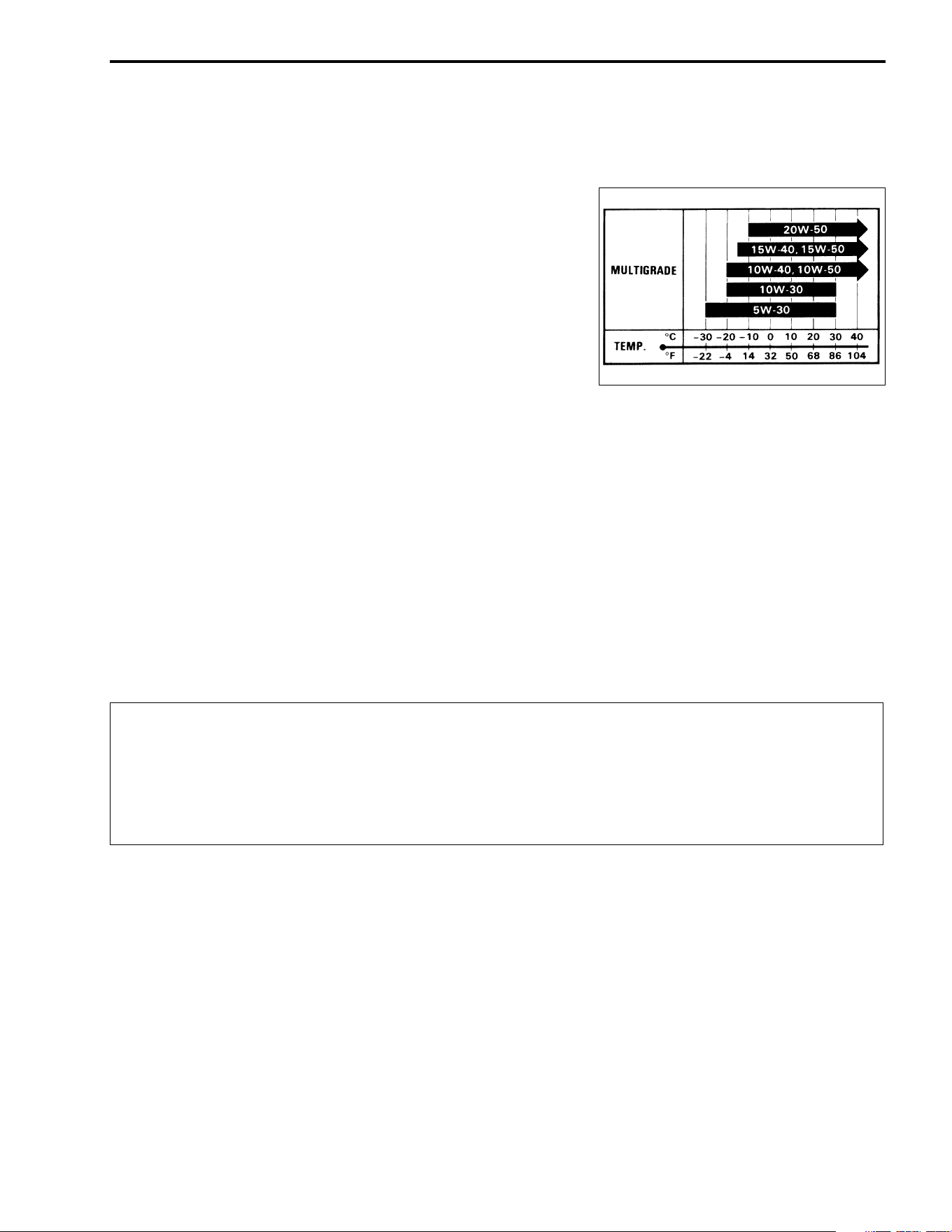
ENGINE OIL (For USA)
SUZUKI recommends the use of SUZUKI PERFORMANCE 4
MOTOR OIL or oils that meet API service classifications SF or
SG and that have a viscosity rating of SAE 10W-40. If engine oil
with a rating of SAE 10W-40 is not available, select an alter-
native according to the chart.
ENGINE OIL (For the other countries)
Use a premium quality 4-stroke motor oil to ensure longer ser-
vice life of your vehicle. Use only oils that meet API service clas-
sifications SF or SG and that have a viscosity rating of SAE
10W-40. If engine oil with a rating of SAE 10W-40 is not avail-
able, select an alternative according to the chart.
FRONT AND REAR DRIVE GEAR OIL
Use hypoid gear oil that meets the API service classification GL-5 and is rated SAE #90. Use a hypoid gear
oil with a rating of SAE #80 if the vehicle is operated where the ambient temperature is below 0°C (32°F).
BRAKE FLUID
# Specification and classification: DOT 4
!
ENGINE COOLANT
Since antifreeze also has corrosion- and rust-inhibiting properties, always use engine coolant containing
antifreeze, even if the atmospheric temperature does not go below the freezing point.
Use an antifreeze designed for aluminum radiators. SUZUKI recommends the use of SUZUKI COOLANT
antifreeze. If this is not available, use an equivalent antifreeze for aluminum radiators.
Mix only distilled water with the antifreeze. Other types of water can corrode and clog the aluminum radiator.
Mix distilled water and antifreeze at a ratio of 50 : 50 – 40 : 60.
For more information, refer to page 6-2 in the Cooling System section.
This vehicle uses a glycol-based brake fluid. Do not use or mix different types of brake fluid
such as silicone-based and petroleum-based fluids for refilling the system, otherwise serious
damage will result to the brake system.
Never use any brake fluid taken from old, used, or unsealed containers.
Never reuse brake fluid left over from the last servicing or which has been stored for a long
period of time.

1-6 GENERAL INFORMATION
"
BREAK-lN PROCEDURES
During manufacturing only the best possible materials are used and all machined parts are finished to a very
high standard. It is still necessary to allow the moving parts to “BREAK-lN” before subjecting the engine to
maximum stresses. The future performance and reliability of the engine depends on the care and restraint
exercised during its early life. Refer to the following break-in engine speed recommendations.
• Keep to these breake-in engine speed limits.
Break-in engine speeds
Initial 500 km (300 miles): Less than ½ throttle
• Upon reaching an odometer reading of 500 km (300 miles) you can subject the vehicle to full throttle oper-
ation, for short periods of time.
The percentage of antifreeze in the coolant should be between 50 to 60%. If the percentage of
antifreeze is above or below this range the coolant’s frost protection and rust-inhibiting capa-
bilities will be reduced. Always keep the antifreeze content above 50% even if the atmospheric
temperature does not go below the freezing point.
GENERAL INFORMATION 1-7
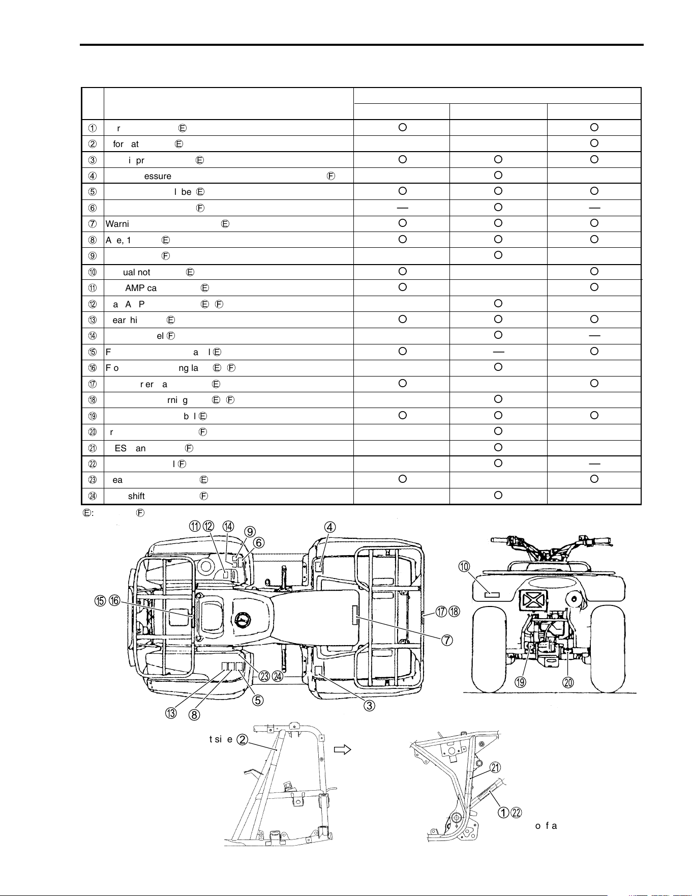
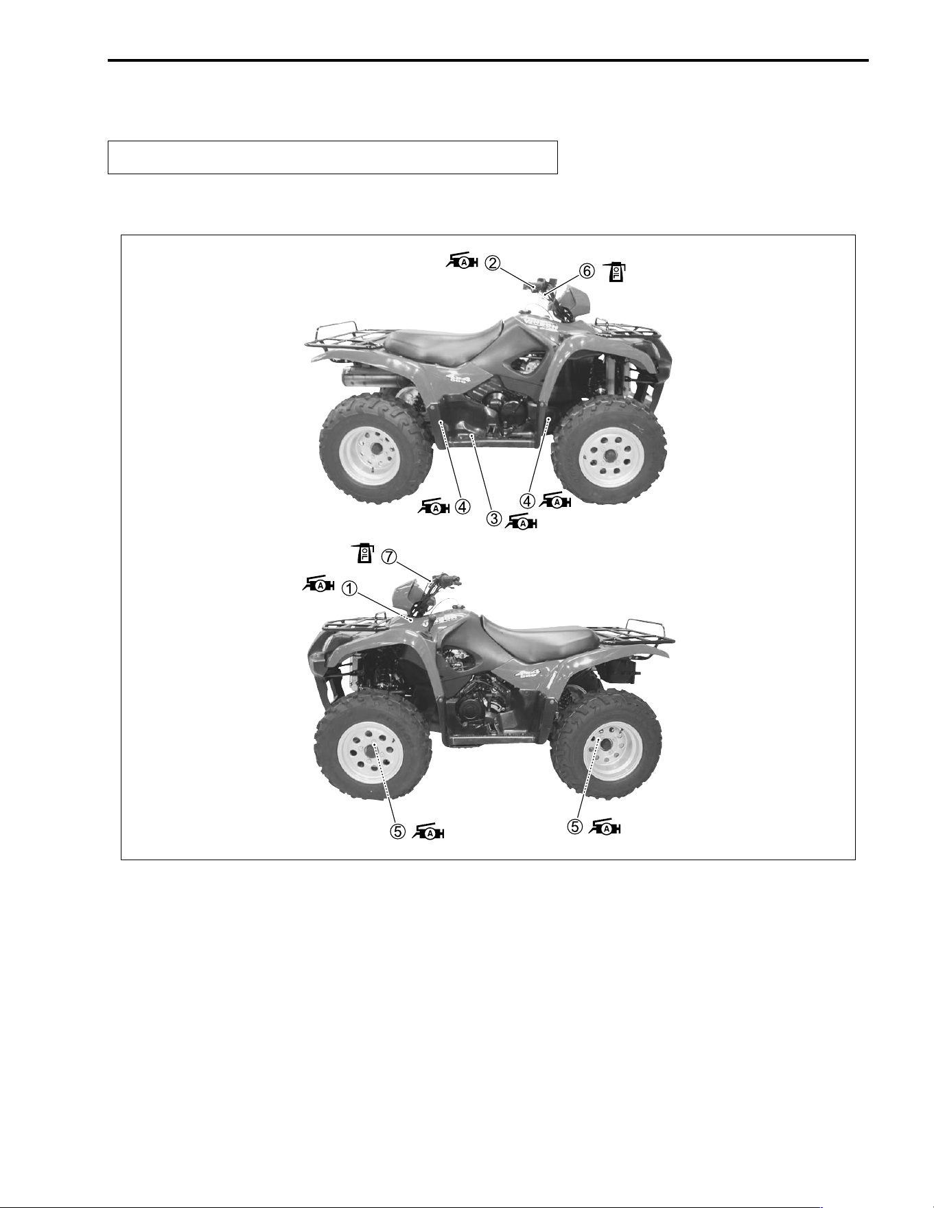
INFORMATION LABELS
LABEL or PLATE NAMENO
APPLIED SPECIFICATION
E-03 E-28 E-33
E
: English
F
: French
1
Certification plate
E
¡
—
¡
2
Information label
E
——
¡
3
Tire air pressure label
E
¡ ¡ ¡
4
Tire air pressure label and warning no-passenger label
F
—
¡
—
5
General warning label
E
¡ ¡ ¡
6
General warning label
F
—
¡
—
7
Warning no-passenger label
E
¡ ¡ ¡
8
Age, 16 Iabel
E
¡ ¡ ¡
9
Age, 16 Iabel
F
—
¡
—
0
Manual notice label
E
¡
—
¡
A
Max AMP caution label
E
¡
—
¡
B
Max AMP caution label
E
,
F
—
¡
—
C
Gearshift label
E
¡¡¡
D
Gearshift label
F
—
¡
—
E
Front carrier warning label
E
¡
—
¡
F
Front carrier warning label
E
,
F
—
¡
—
G
Rear carrier warning label
E
¡
—
¡
H
Rear carrier warning label
E
,
F
—
¡
—
I
Trailer to warning label
E
¡ ¡ ¡
J
Trailer to warning label
F
—
¡
—
K
ICES Canada label
F
—
¡
—
L
Compliance label
F
—
¡
—
M
Gear shift pattern label
E
¡
—
¡
N
Gear shift pattern label
F
—
¡
—
Front
Right side
of frame
left side of frame

1-8 GENERAL INFORMATION
SPECIFICATIONS
DIMENSIONS AND DRY MASS
Overall length.......................................................2 095 mm (82.5 in)
Overall width ........................................................1 170 mm (46.1 in)
Overall height.......................................................1 200 mm (47.2 in)
Wheelbase ...........................................................1 270 mm (50.0 in)
Ground clearance ................................................ 250 mm ( 9.8 in)
Seat height........................................................... 860 mm (33.9 in)
Dry mass.............................................................. 274 kg (604 lbs)
Front track............................................................ 940 mm (37.0 in)
Rear track ............................................................ 930 mm (36.6 in)
ENGINE
Type .....................................................................4-stroke, liquid-cooled, OHC
Number of cylinders .............................................1
Bore .....................................................................87.5 mm (3.445 in)
Stroke...................................................................82.0 mm (3.228 in)
Displacement .......................................................493 cm³ (30.1 cu in)
Compression ratio................................................10.2 : 1
Carburetor............................................................KEIHIN CVK36, single
Air cleaner............................................................Polyurethane foam element
Starter system......................................................Electric and recoil starter
Lubrication system ...............................................Wet sump
Idle speed ............................................................1 300 ± 100 r/min
DRIVE TRAIN
Clutch...................................................................Wet multi-plate, automatic, centrifugal type
Transmission ........................................................ 5-forward constant mesh, 1-reverse with 2-transfer
Gearshift pattern ..................................................All up (Foot operated)
Primary reduction ratio.........................................2.032 (63/31)
Final reduction ratio .............................................4.080 (17/15 × 36/10)
Subtransmission reduction ratio, High ................1.592 (43/27)
Low .................2.419 (22/23 × 43/17)
Gear ratios, Low ...................................................3.090 (34/11)
2nd....................................................1.750 (28/16)
3rd ....................................................1.200 (24/20)
4th.....................................................0.875 (21/24)
Top ...................................................0.724 (21/29)
Reverse ............................................2.636 (29/11)
Drive system ........................................................Shaft drive

GENERAL INFORMATION 1-9
CHASSIS
Front suspension................................................. Independent, double wishbone, coil spring, oil damped
Rear suspension ................................................. Swingarm type, coil spring, oil damped
Front wheel travel................................................ 180 mm (7.1 in)
Rear wheel travel ................................................ 200 mm (7.9 in)
Caster.................................................................. 3.3°
Trail ..................................................................... 17 mm (0.67 in)
Toe-in .................................................................. 7 mm (0.3 in)
Camber ............................................................... 0.45°
Steering angle ..................................................... 45° (right & left)
Turning radius ..................................................... 3.0 m (9.8 ft)
Front brake.......................................................... Disc brake, twin
Rear brake .......................................................... Disc brake
Front tire size ...................................................... AT25 × 8-12 ✩ ✩, tubeless
Rear tire size ....................................................... AT25 × 10-12 ✩ ✩, tubeless
ELECTRICAL
lgnition type ......................................................... Electronic ignition (CDl)
lgnition timing ...................................................... 10° B.T.D.C at 1 300 r/min
Spark plug ........................................................... NGK CR6E or DENSO U20ESR-N
Battery................................................................. 12 V 50.4 kC (14 Ah)/10 HR
Generator ............................................................ Three-phase A.C. generator
Main fuse............................................................. 30 A
Fuse .................................................................... Head-Hi 10/Head-Lo 10/Ignition 15/Aux 10/P-Source 10 A
Headlight ............................................................. 12 V 30/30 W
AUX lamp ............................................................ 12 V 40 W
Brake light/Taillight.............................................. 12 V 21/5 W
Speedometer light ............................................... LED
Coolant temperature gauge light......................... LED
Neutral indicator light .......................................... LED
High beam indicator light..................................... LED
Reverse indicator light......................................... LED
Parking indicator light.......................................... LED
CAPACITIES
Fuel tank, including reserve................................. 19.0 L (5.0/4.2 US/Imp gal)
reserve................................................ 4.2 L (1.1/0.9 US/Imp gal)
Engine oil, oil change .......................................... 3 400 ml (3.6/3.0 US/Imp qt)
with filter change................................ 3 600 ml (3.8/3.2 US/Imp qt)
overhaul ............................................. 4 000 ml (4.2/3.5 US/Imp qt)
Differential gear oil .............................................. 370 ml (12.5/13.0 US/Imp oz)
Final gear oil, overhaul........................................ 350 ml (11.8/12.3 US/Imp oz)
Coolant................................................................ 2.0 L (2.1/1.8 US/Imp qt)
NOTE:
* These specifications are subject to change without notice.

1-10 GENERAL INFORMATION
COUNTRY AND AREA CODES
The following codes stand for the applicable countries and areas.
CODE COUNTRY OR AREA
E-03
E-28
E-33
USA
Canada
California (USA)

2
6
PERIODIC MAINTENANCE 2-1
CONTENTS
PERIODIC MAINTENANCE
PERIODIC MAINTENANCE SCHEDULE ............................................2- 2
PERIODIC MAINTENANCE CHART ...........................................2- 2
MAINTENANCE AND TUNE-UP PROCEDURES ...............................2- 3
AIR CLEANER .............................................................................2- 3
EXHAUST PIPE NUTS AND MUFFLER BOLTS ........................2- 4
VALVE CLEARANCE ..................................................................2- 5
SPARK PLUG ..............................................................................2- 6
FUEL LINE ...................................................................................2- 7
THROTTLE CABLE PLAY ...........................................................2- 8
ENGINE IDLE SPEED ..................................................................2- 8
ENGINE OIL AND OIL FILTER ....................................................2- 9
DIFFERENTIAL GEAR AND FINAL BEVEL GEAR OIL .............2-11
ENGINE COOLANT .....................................................................2-12
RADIATOR HOSES .....................................................................2-13
CLUTCH .......................................................................................2-14
SPARK ARRESTER ....................................................................2-14
BRAKES .......................................................................................2-15
BRAKE FLUID .............................................................................2-16
BRAKE HOSES ...........................................................................2-18
TIRES ...........................................................................................2-18
STEERING SYSTEM ....................................................................2-19
SUSPENSIONS ............................................................................2-20
CHASSIS NUTS AND BOLTS .....................................................2-21
GENERAL LUBRICATION ..........................................................2-23
COMPRESSION PRESSURE CHECK .................................................2-24
COMPRESSION TEST PROCEDURE .........................................2-24
OIL PRESSURE CHECK ......................................................................2-25
OIL PRESSURE TEST PROCEDURE .........................................2-25
INITIAL ENGAGEMENT AND CLUTCH LOCK-UP INSPECTION ......2-26
INITIAL ENGAGEMENT INSPECTION .......................................2-26
CLUTCH LOCK-UP INSPECTION ...............................................2-27
PARKING INSPECTION .......................................................................2-28
2-2 PERIODIC MAINTENANCE
PERIODIC MAINTENANCE SCHEDULE
The chart below lists the recommended intervals for all the required periodic service work necessary to keep
the vehicle operating at peak performance and economy. Maintenance intervals are expressed in terms of
kilometers, miles and months, and are dependent on whichever comes first.
NOTE:
More frequent servicing may be performed on vehicles that are use under severe conditions.
PERIODIC MAINTENANCE CHART
I = Inspect and adjust, clean, lubricate, or replace as necessary.
R = Replace
T = Tighten
C = Clean
L = Lubricate
Interval
Item
km Initial 200 Every 1 000 Every 2 000
miles Initial 100 Every 600 Every 1 200
months 1 3 6
Air cleaner — C C
Exhaust pipe nuts and muffler bolts T T T
Valve clearance I — I
Spark plug
—— I
Replace every 6 000 km (4 000 miles).
Fuel line
—I I
Replace every 4 years.
Throttle cable play I I I
Engine idle speed I I I
Engine oil and oil filter R — R
Front differential gear oil/Final gear oil
—— I
Replace every 2 years.
Engine coolant Replace every 2 years.
Radiator hose
—I I
Replace every 4 years.
Clutch — — I
Spark arrester — — C
Brakes I I I
Brake fluid
—I I
Replace every 2 years.
Brake hose
—— I
Replace every 4 years.
Tires — I I
Steering system I I I
Suspensions — — I
Chassis nuts and bolts T T T
General lubrications — L L
PERIODIC MAINTENANCE 2-3
MAINTENANCE AND TUNE-UP PROCEDURES
This section describes the servicing procedures for each item
mentioned in the Periodic Maintenance chart.
AIR CLEANER
If the air cleaner is clogged with dust, intake resistance will be
increased, with a resultant decrease in power output and an
increase in fuel consumption. Check and clean the air cleaner
element in the following manner.
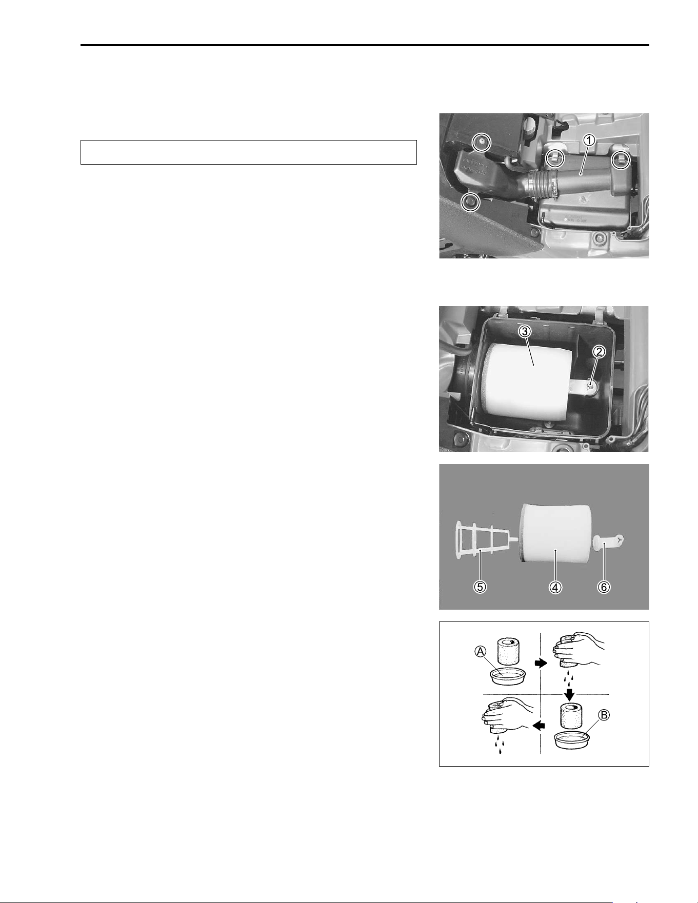
• Remove the air cleaner case cover
1.
NOTE:
Be careful not to drop the O-ring into the air cleaner box that is
attached to the air cleaner case cover.
• Loosen screw
2 to remove the air cleaner element
3.
• Separate the polyurethane foam element
4, element frame
5 and element holder
6.
• Fill a wash pan of a proper size with a non-flammable clean-
ing solvent. Immerse the air cleaner element in the cleaning
solvent and wash it.
• Press the air cleaner element between the palms of both
hands to remove the excess solvent: do not twist or wring the
element or it will tear.
• Immerse the element in motor oil, and then squeeze out the
excess oil leaving the element slightly wet.
A Non-flammable cleaning solvent
B Motor oil SAE #30 or SAE 10W-40
Clean every 1 000 km (600 miles, 3 months).
2-4 PERIODIC MAINTENANCE
!
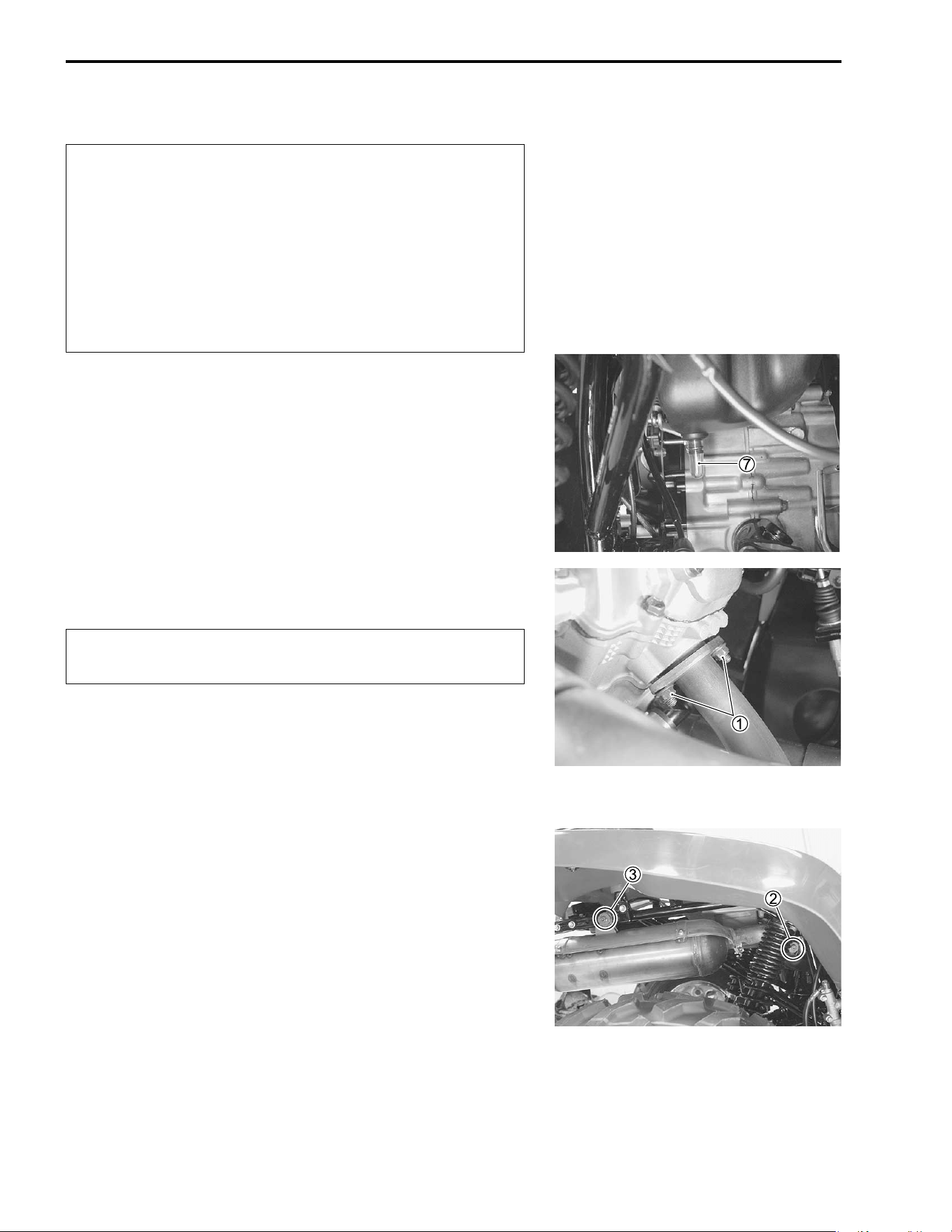
• Remove the drain cap
7 of the air cleaner box to allow any
water to drain out.
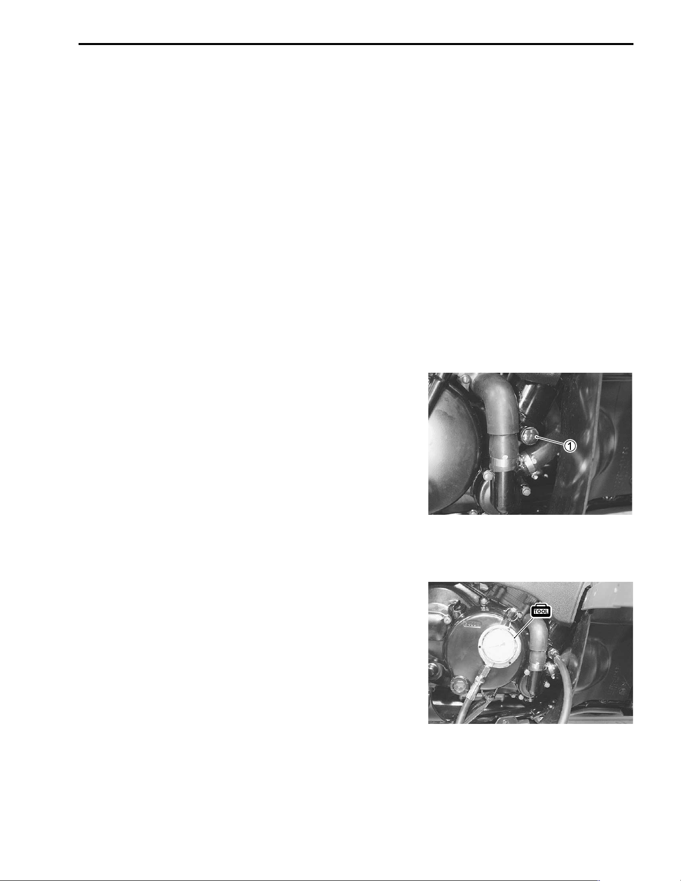
EXHAUST PIPE NUTS AND MUFFLER
BOLTS
• Remove the right inner fender. (" 7-6)
• Tighten the exhaust pipe nuts
1, muffler connection bolt
2,
and muffler mounting bolt
3 to the specified torque.
# Exhaust pipe nut: 23 N·m (2.3 kgf-m, 16.5 lb-ft)
Muffler connection bolt: 23 N·m (2.3 kgf-m, 16.5 lb-ft)
Muffler mounting bolt: 23 N·m (2.3 kgf-m, 16.5 lb-ft)
* Inspect the air cleaner element for tears. A torn ele-
ment must be replaced.
* If driving under dusty conditions, clean the air
cleaner element more frequently. The surest way to
accelerate engine wear is to operate the engine with-
out the element or with torn element. Make sure that
the air cleaner element is in good condition at all
times. Life of the engine depends largely on this
component!
Tighten initially at 200 km (100 miles, 1 month) and
every 1 000 km (600 miles, 3 months) thereafter.
PERIODIC MAINTENANCE 2-5
VALVE CLEARANCE
Excessive valve clearance results in valve noise and insufficient
valve clearance results in valve damage and reduced power.
Check the intake and exhaust valve clearances at the distances
indicated above and adjust the valve clearances to specification,
if necessary.
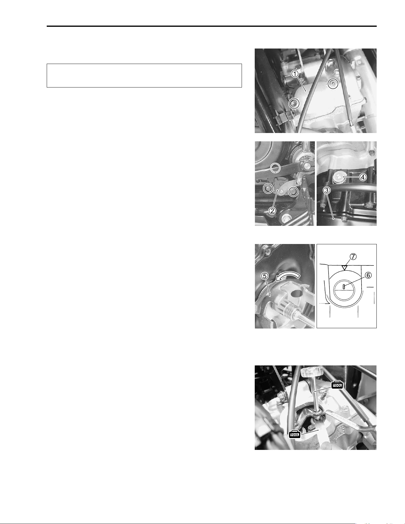
• Remove the fuel tank. ("5-3)
• Remove the spark plug. ("2-6)
• Remove the valve inspection caps
1.
• Rmove the left mud guard. ("7-8)
• Remove the gear switch
2.
• Remove the recoil starter
3. ("3-13)
• Remove the TDC plug
4.
$ Valve clearance (when cold)
IN: 0.05 – 0.10 mm (0.002 – 0.004 in)
EX: 0.17 – 0.22 mm (0.007 – 0.009 in)
NOTE:
Valve clearance is to be checked when the engine is cold.
The intake and exhaust valves must be checked and adjusted
when the piston is at Top-Dead-Center (TDC) of the compres-
sion stroke.
• Turn the crankshaft until the piston reaches TDC on the com-
pression stroke by turning the starter cup
5. Turn the starter
cap until the line
6 on the generator rotor is aligned with the
mark
7 on the crankcase
• The crankshaft can be turned to align the line
6 and mark
7
by slowly pulling the recoil starter lope without removing the
ricoil stater.
• Insert the thickness gauge to check the clearance between
the valve stem end and the adjusting screw on the rocker
arm.
% 09900-20803: Thickness gauge
• If the clearance is out of specification, bring it into the speci-
fied range using the special tool.
% 09917-14920: Valve adjuster driver
# Valve clearance adjuster locknut:
10 N·m (1.0 kgf-m, 7.0 lb-ft)
Inspect initially at 200 km (100 miles, 1 month) and
every 2 000 km (1 200 miles, 6 months) thereafter.
2-6 PERIODIC MAINTENANCE
!
• Install the spark plug and TDC plug.
# TDC plug: 23 N·m (2.3 kgf-m, 16.5 lb-ft)
• Apply grease to the O-rings and install the O-rings valve
inspection caps.
• Tighten the valve inspection cap bolts/nuts to the specified
torque.
& 99000-25030: SUZUKI SUPER GREASE “A” (USA)
99000-25010: SUZUKI SUPER GREASE “A” (Others)
# Valve inspection cap bolt/nut: 10 N·m (1.0 kgf-m, 7.0 lb-ft)
SPARK PLUG
• Remove the spark plug cap
1.
• Remove the spark plug with the spark plug wrench.
% 09930-10121: Spark plug wrench set
HEAT RANGE
• Check spark plug heat range by observing electrode color. If
the electrode of the spark plug is wet appearing or dark color,
replace the spark plug with hotter type one. If it is white or
glazed appearing, replace the spark plug with colder type one.
CARBON DEPOSITS
Check to see if there are carbon deposits on the spark plug. If
carbon is deposited, remove it using a spark plug cleaner
machine or carefully use a tool with a pointed end.
Securely tighten the locknut after completing adjust-
ment.
Inspect every 2 000 km (1 200 miles, 6 months).
Replace every 6 000 km (4 000 miles).
Standard Cold type
NGK CR6E CR7E
DENSO U20ESR-N U22ESR-N
PERIODIC MAINTENANCE 2-7
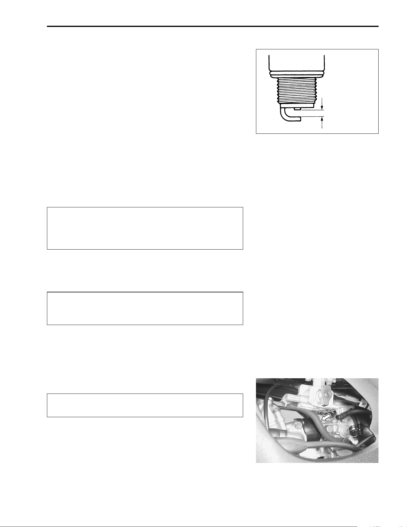
SPARK PLUG GAP
Measure the spark plug gap using a thickness gauge. If the
spark plug gap is out of specification, adjust the gap.
$ Standard
Spark plug gap: 0.7 – 0.8 mm (0.028 – 0.031 in)
% 09900-20803: Thickness gauge
ELECTRODE
Check the condition of the electrode.
If the electrode is extremely worn or burnt, replace the spark
plug with a new one.
Also, replace the spark plug if it has a broken insulator, dam-
aged threads, etc.
!
SPARK PLUG INSTALLATION
!
• Insert the spark plug and finger tighten it to the cylinder head
and then tighten it to the specified torque.
# Spark plug: 11 N·m (1.1 kgf-m, 8.0 lb-ft)
FUEL LINE
Inspect the fuel hose for damage and fuel leakage. If any dam-
ages are found, replace the fuel hoses with a new one.
• When replacing the fuel hoses, remove the fuel tank cover.
("7-5)
0.7 – 0.8 mm
(0.028 – 0.031 in)
Check the thread size and reach when replacing the
spark plug. If the reach is too short, carbon will be
deposited on the screw portion of the spark plug hole
and engine damage may result.
To avoid damaging the cylinder head threads; first,
finger tighten the spark plug, and then tighten it to the
specified torque using the spark plug wrench.
Inspect every 1 000 km (600 miles, 3 months).
Replace every 4 years.
2-8 PERIODIC MAINTENANCE
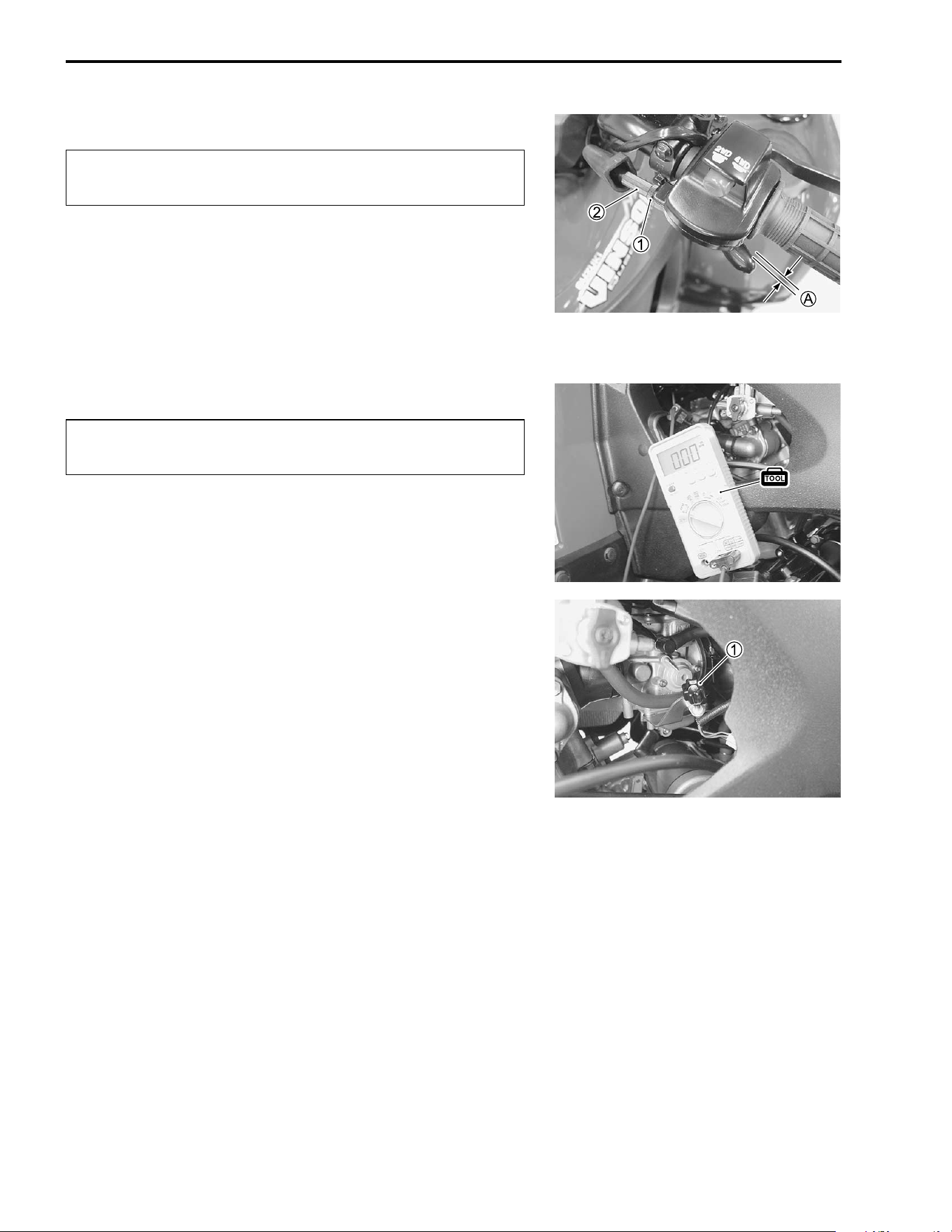
THROTTLE CABLE PLAY
Adjust the throttle cable play
A as follows.
• Loosen the locknut
1 of the throttle cable.
• Turn the adjuster
2 in or out to obtain the correct play.
$ Throttle cable play: 3 – 5 mm (0.12 – 0.20 in)
• After adjusting the throttle cable play, tighten the locknut
1.
ENGINE IDLE SPEED
NOTE:
Make this adjustment when the engine is warmed up.
• Connect the electric tachometer or the multi circuit tester to
the high-tension cord.
• Start the engine and set the engine idle speed between 1 200
and 1 400 r/min by turning the throttle stop screw knob
1.
$ Engine idle speed: 1 300 ± 100 r/min
% 09900-26006: Tachometer, or
09900-25008: Multi circuit tester set
Inspect initially at 200 km (100 miles, 1 month) and
every 1 000 km (600 miles, 3 months) thererafter.
Inspect initially at 200 km (100 miles, 1 month) and
every 1 000 km (600 miles, 3 months) thereafter.
PERIODIC MAINTENANCE 2-9
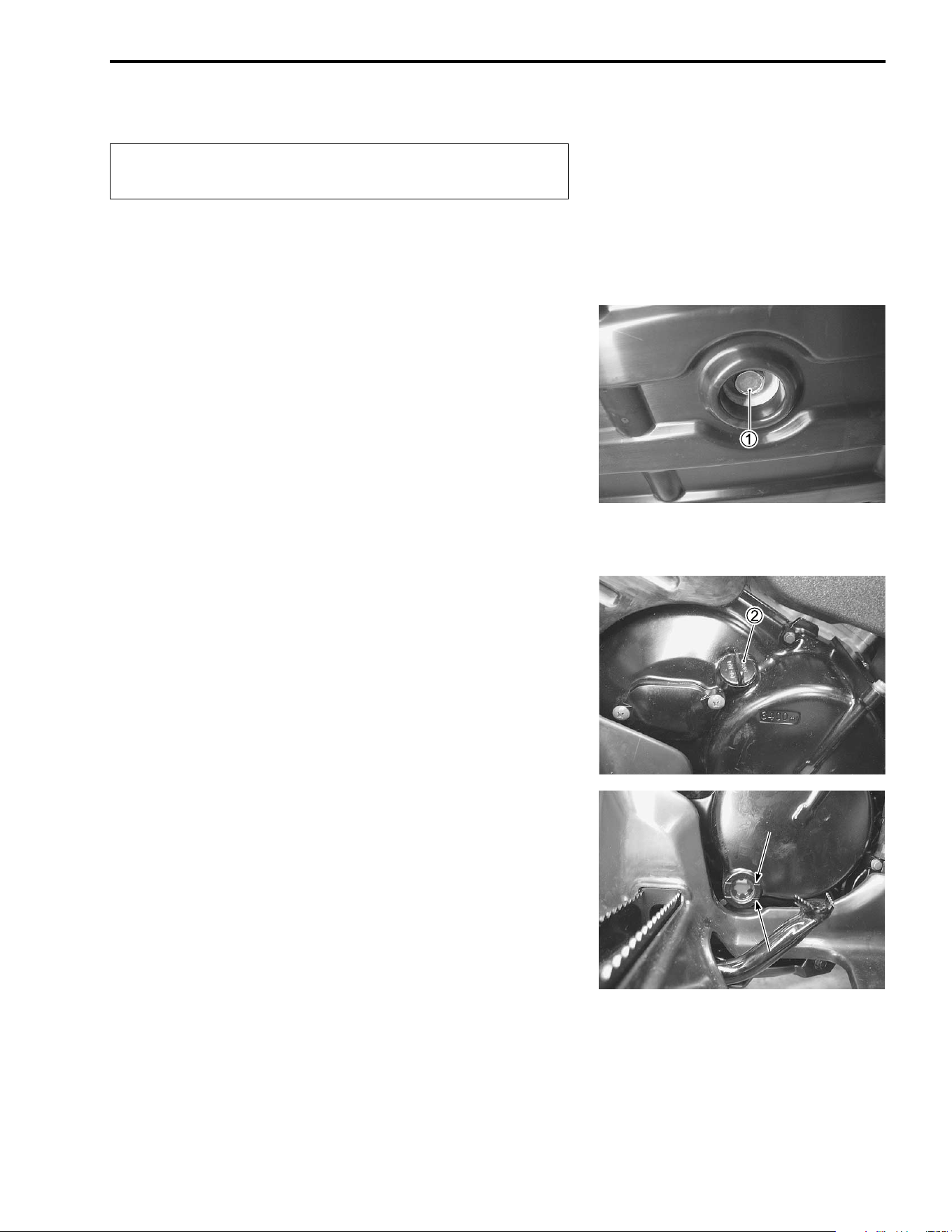
ENGINE OIL AND OIL FILTER
The oil should be changed while the engine is warm. Oil filter
replacement at the above intervals, should be done together
with the engine oil change.
ENGINE OIL REPLACEMENT
• Place an oil pan under the drain plug
1, and then drain out
the engine oil by removing the engine oil drain plug
1 and
engine oil filler cap
2.
• Reinstall the drain plug
1 and the gasket. Tighten the engine
oil drain plug
1 to the specicied torque, and then pour the
new oil through the oil filler hole. When performing an oil
change (without oil filter replacement), the engine will hold
about 3.4 L (3.6 US qt, 3.0 lmp qt) of oil. Use an engine oil
that meets the API service classifications SF or SG and that
has a viscosity rating of SAE 10W-40.
# Engine oil drain plug: 23 N·m (2.3 kgf-m, 16.5 lb-ft)
• Install the oil filler cap
2.
• Start the engine and allow it to run for a few minutes at idling
speed.
• Turn off the engine and wait about three minutes, then check
the oil level through the inspection window. If the level is
below mark “L”, add oil to “F” level. If the level is adove mark
“F”, drain oil to “F” level.
Replace initially at 200 km (100 miles, 1 month) and
every 2 000 km (1 200 miles, 6 months) thereafter.
FF
L
L
2-10 PERIODIC MAINTENANCE
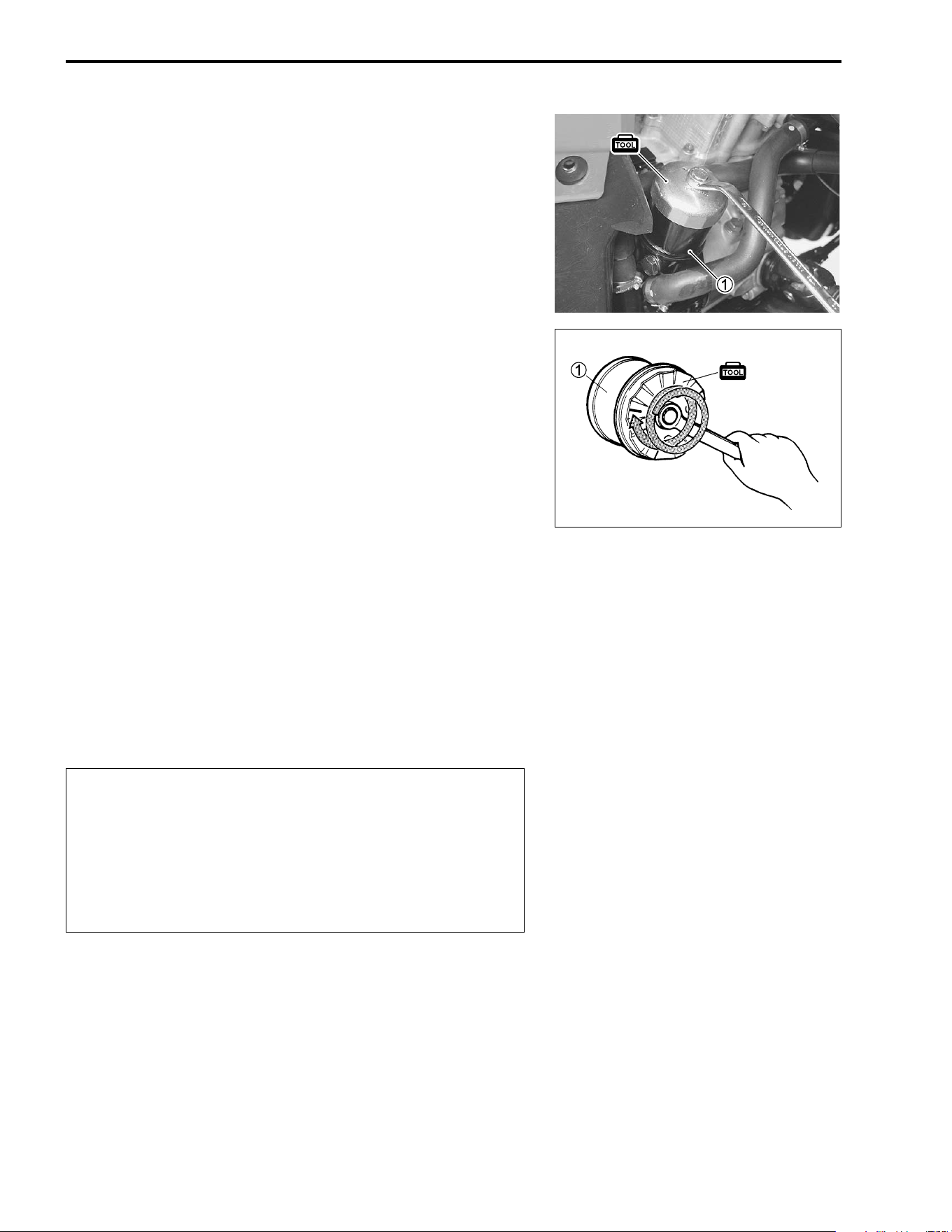
OIL FILTER REPLACEMENT
• Drian the engine oil. ("2-9)
• Remove the right inner fender. (" 7-6)
• Remove the oil filter
1 using the special tool.
• Apply engine oil lightly to the gasket of the new oil filter,
before installation.
% 09915-40610: Oil filter wrench
• Install the new oil filter to the engine. Turn it by hand until the
oil filter gasket has contacted the oil filter mounting surface.
Then, tighten the oil filter two full turns using the special tool.
% 09915-40610: Oil filter wrench
NOTE:
To properly tighten the oil filter, use the special tool. Never
tighten the oil filter by hand.
• Pour the new engine oil through the oil filler. When performing
the oil filter change, the engine will hold about 3.6 L (3.8 US
qt, 3.2 Imp qt) of oil.
• After three minutes engine idling, check the oil level. ("2-9)
• Add new engine oil and check the oil level. ("2-9)
$ Engine oil capacity
Oil change: 3.4 L (3.6 US qt, 3.0 lmp qt)
Oil and filter change: 3.6 L (3.8 US qt, 3.2 lmp qt)
Engine overhaul: 4.0 L (4.2 US qt, 3.5 lmp qt)
!
After contacting the gasket,
tighten 2 turns.
ONLY USE A GENUINE SUZUKI MOTORCYCLE OIL
FILTER.
Other manufacture’s oil filters may differ in thread
specifications (thread diameter and pitch), filtering
performance and durability which may lead to engine
damage or oil leaks. Also, do not use a GENUINE
SUZUKI AUTOMOBILE OIL FILTER on this vehicle.
PERIODIC MAINTENANCE 2-11
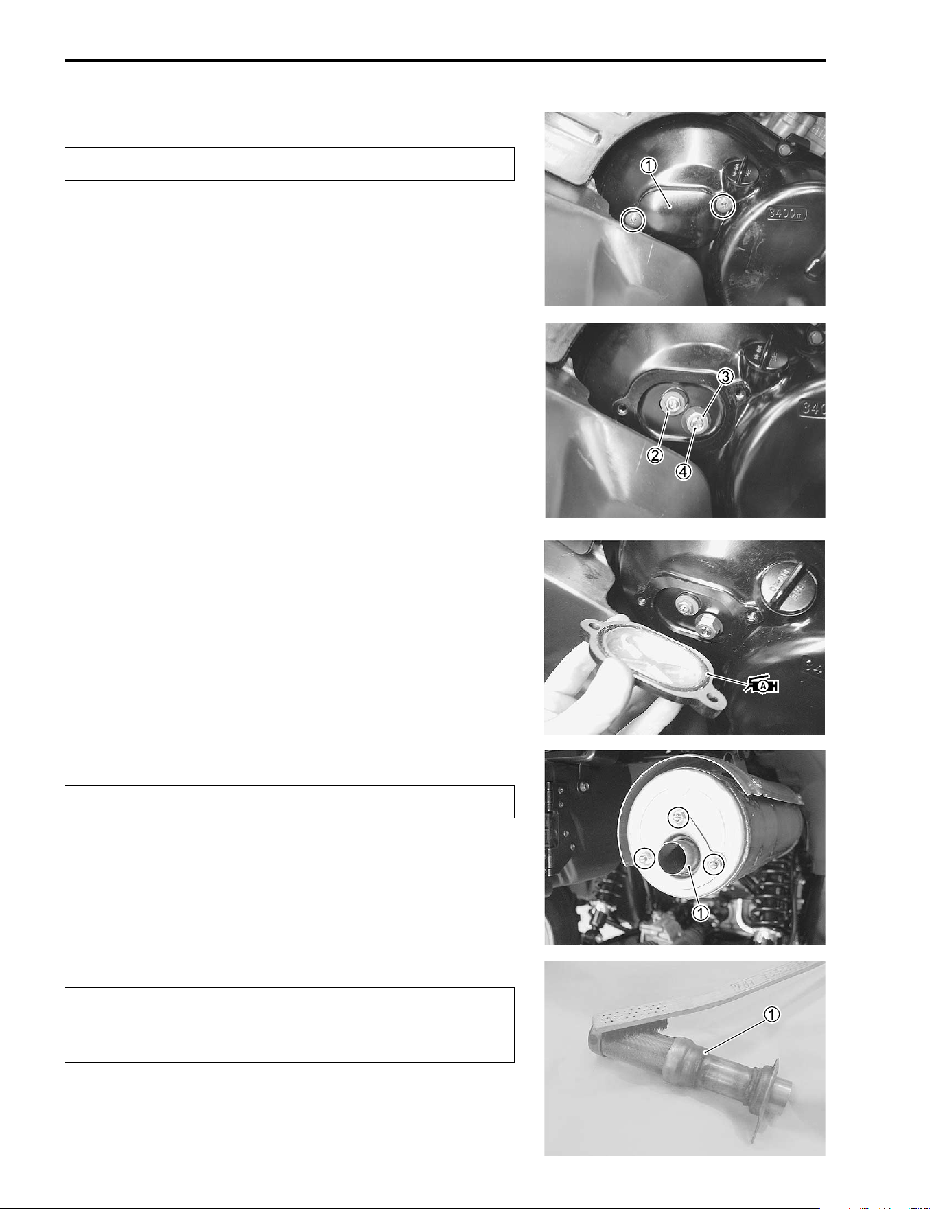
DIFFERENTIAL GEAR AND FINAL BEVEL
GEAR OIL
To change the differential gear and final bevel gear oil, locate
the vehicle on a level position and carry out the following steps.
Use SAE #90 hypoid gear oil which is rated GL-5 under the API
classification system. Use hypoid gear oil SAE 80, API grade
GL-5, if the vehicle is ridden where the ambient temperature is
below 0°C or 32°F.
DIFFERENTIAL GEAR OIL
• Remove the under cover. ("3-4)
• Place an oil pan below the differential gear case, and then
drain the oil by removing the drain plug
1 and filler cap
2.
• Tighten the drain plug
1 to the specified torque and pour the
specified oil through the filler hole until it over flows.
• Tighten the filler cap
2 to the specified torque.
$ Differential gear oil capacity:
270 – 370 ml (9.1 – 12.5 US oz, 9.5 – 13.0 lmp oz)
# Differential gear oil drain plug:
32 N·m (3.2 kgf-m, 23.0 lb-ft)
Differential gear oil filler cap:
35 N·m (3.5 kgf-m, 25.5 lb-ft)
FINAL BEVEL GEAR OIL
• Remove the final bevel gear case under cover
1 by removing
three bolts.
Inspect every 2 000 km (1 200 miles, 6 months).
Replace every 2 years.
2-12 PERIODIC MAINTENANCE
• Place an oil pan below the final gear case, and then drain the
oil by removing the drain plug
2 and filler cap
3.
• Tighten the drain plug
2 to the specified torque.
# Final bevel gear oil drain plug:
33 N·m (3.3 kgf-m, 24.0 lb-ft)
• Remove the oil level check bolt
4 and pour the specified oil
through the filler hole until the oil over flows from the oil level
check hole.
• Tighten the filler cap
3 and the oil level check bolt
4.
$ Final bevel gear oil capacity:
250 – 350 ml (8.5 – 10.1 US oz, 8.8 – 10.6 lmp oz)
# Final bevel gear oil filler cap:
33 N·m (3.3 kgf-m, 24.0 lb-ft)
ENGINE COOLANT
ENGINE COOLANT LEVEL CHECK
• Check the engine coolant level by observing the upper
1 and
lower
2 lines on the engine coolant reservoir.
• If the level is below the lower line, add engine coolant until the
level reaches the upper line.
ENGINE COOLANT REPLACEMENT
• Remove the radiator cap lid
1.
Repalce the engine coolant every 2 years.
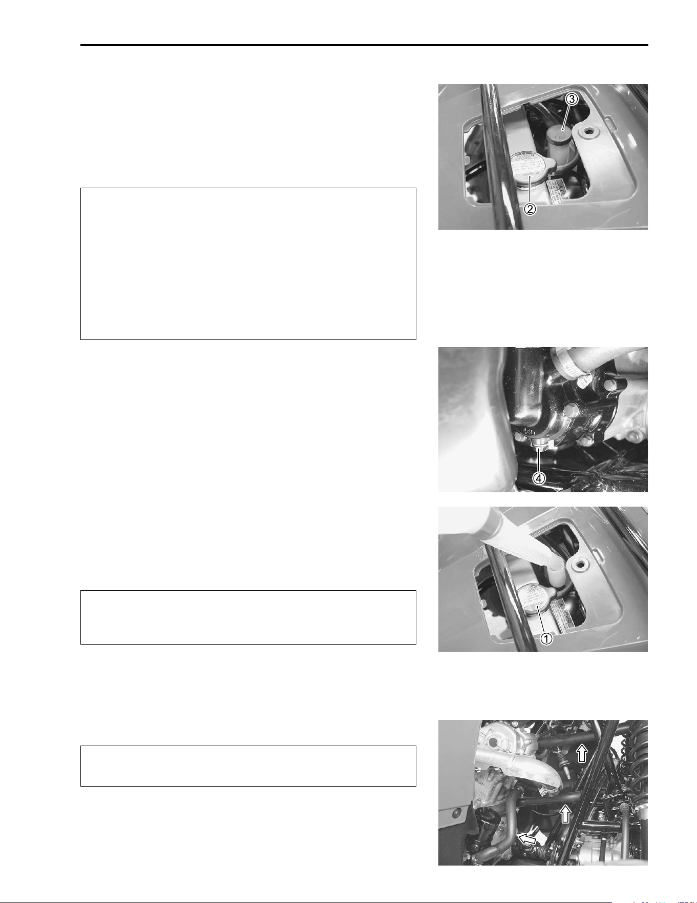
PERIODIC MAINTENANCE 2-13
• Remove the radiator cap
2 and engine coolant reservoir cap
3.
• Remove the right inner fender. ("7-6)
• Place a pan below the water pump, and then drain the engine
coolant by removing the drain plug
4.
'
• Flush the radiator with fresh water, if necessary.
• Tighten the drain plug securely.
• Pour the specified engine coolant into the reservoir.
( Engine coolant:
Use and antifreeze designed for aluminum radiators
mixed with distilled water only.
Water/antifreeze mixture ratio: 50 : 50 – 40 : 60
NOTE:
For engine coolant information, refer to page 6-2.
• Install the radiator cap
1 securely.
• After warming up and cooling down the engine, add the spec-
ified engine coolant until the level is between the upper and
lower lines on the engine coolant reservoir.
!
$ Engine coolant capacity:
2 000 ml (2.1 US qt, 1.8 lmp qt)
RADIATOR HOSES
Inspect the radiator hoses for damage and engine coolant leak-
age. If any damages are found, replace the radiator hoses with
new ones.
* Do not open the radiator cap when the engine is hot,
as you may be injured by escaping hot liquid or
vapor.
* Engine coolant may be harmful if swallowed or if it
comes in contact with the skin or eyes. If engine
coolant gets into the eyes or contacts the skin, flush
the eyes or wash the skin thoroughly, with plenty of
water. If engine coolant is swallowed, induce vomit-
ing and call a physician immediately.
Repeat the above procedure several times and make
sure the radiator is filled with engine coolant to the
upper line of the engine coolant reservoir.
Inspect every 1 000 km (600 miles, 3 months).
Replace every 4 years.
2-14 PERIODIC MAINTENANCE
CLUTCH
• Remove the clutch adjuster cap
1.
• Loosen the locknuts
2 and
3.
• Rotate the adjusting screw
4 on the right side counterclock-
wise until it stops.
• Tighten the locknut
2 on the left side.
# Locknut
2: 8 N·m (0.8 kgf-m, 5.7 lb-ft)
• Rotate the adjusting screw
4 on the right side 1/4 – 2/4 turn
clockwise.
• Tighten the locknut
3 by holding the adjuster.
# Locknut
3: 23 N·m (2.3 kgf-m, 16.5 lb-ft)
• Apply grease to the O-ring and install the O-ring clutch
adjuster cap.
• Install the clutch adjuster cap.
& 99000-25030: SUZUKI SUPER GREASE “A” (USA)
99000-25010: SUZUKI SUPER GREASE “A” (Others)
SPARK ARRESTER
• Extract the spark arrester pipe
1 from the muffler.
• Clean the spark arrester pipe
1 by brush.
• Reinstall the spark arrester pipe
1.
'
Inspect every 2 000 km (1 200 miles, 6 months).
Clean every 2 000 km (1 200 miles, 6 months).
Only clean the spark arrester in an open area away
from combustible materials. Exhausted hot carbon
particles can start a fire.
PERIODIC MAINTENANCE 2-15
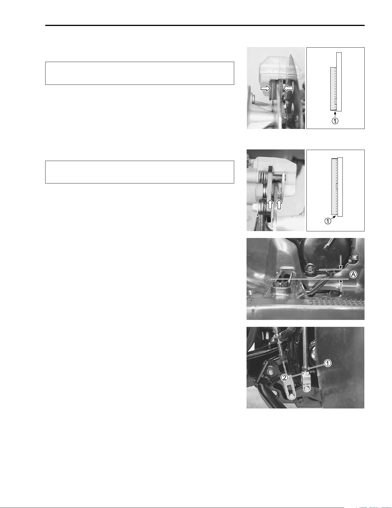
BRAKES
BRAKE PADS
• Remove the front wheels and the right rear wheel. ("7-11)
The extent of brake pads wear can be checked by observing the
limit line
1 on the side of brake pads. When the wear reaches
the limit line, replace the pads with new ones. ("7-20 and 7-
51)
!
# Brake pad mounting bolt (front):
18 N·m (1.8 kgf-m, 13.0 lb-ft)
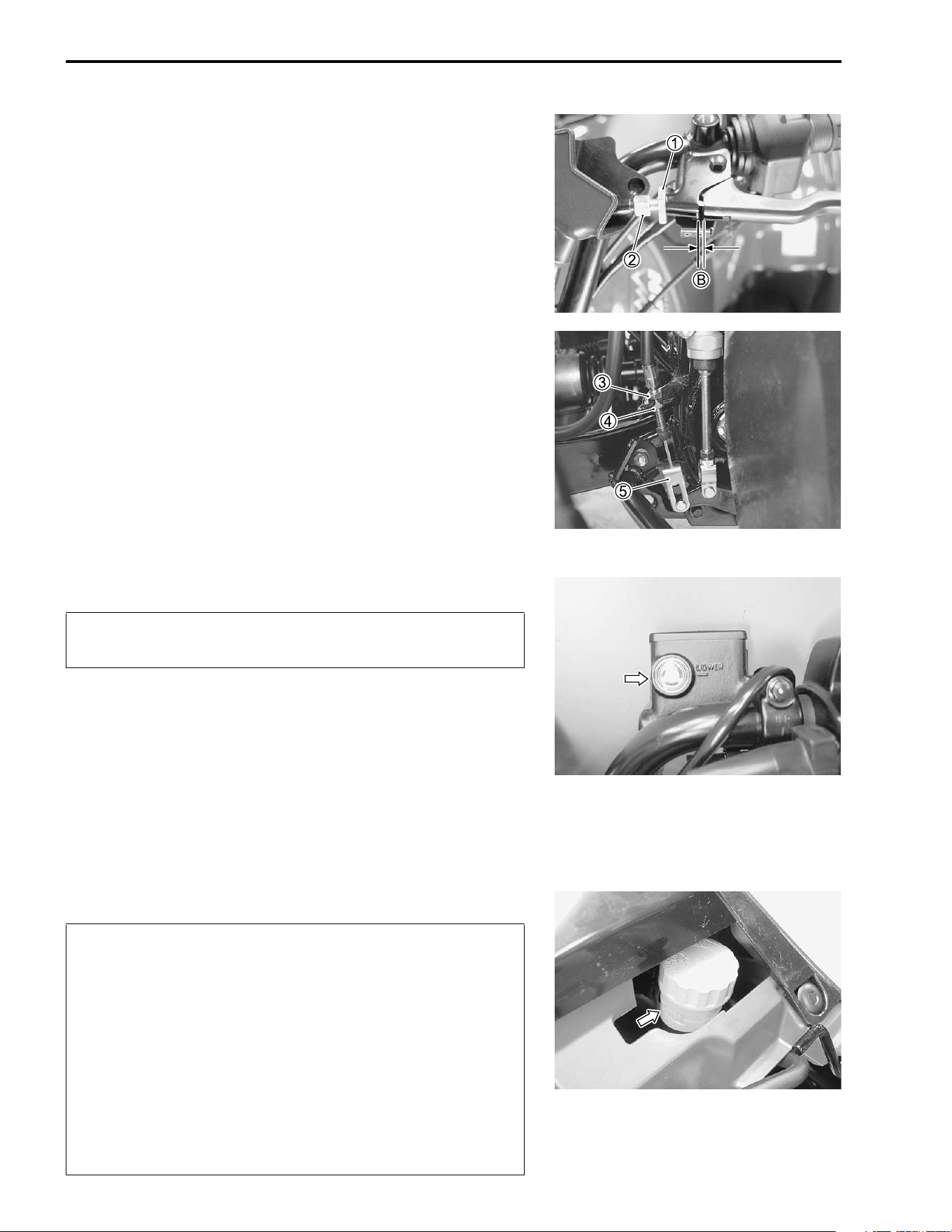
REAR BRAKE PEDAL AND LEVER
The procedure for adjusting the rear brake pedal and brake
lever is as follows:
NOTE:
First adjust the brake pedal, and then adjust the rear brake
lever.
Brake pedal
• Turn the adjuster
1 in or out until the pedal height
A to the
specification, after loosening the locknut
2.
• Tighten the locknut
2 to the specified torque.
$ Brake pedal height
A
AA
A: 5 – 15 mm (0.2 – 0.6 in)
# Rear master cylinder rod locknut:
18 N·m (1.8 kgf-m, 13.0 lb-ft)
Inspect initially at 200 km (100 miles, 1 month) and
every 1 000 km (600 miles, 3 months) thereafter.
Replace the brake pads as a set, otherwise braking
performance will be adversely affected.
FRONT
REAR
2-16 PERIODIC MAINTENANCE
Rear brake lever
• After adjusting the brake pedal, check the rear brake lever
play. The brake lever play
B as measured at the lever holder
should be between 3 – 5 mm (0.1 – 0.2 in) when the lever is
lightly pulled in towards the grip. If adjustment is necessary,
slacken the cable by loosening the locknut
1 and screwing
the adjuster
2 on the brake lever holder all the way in.
$ Rear brake lever play
B
BB
B: 3 – 5 mm (0.1 – 0.2 in)
• Loosen the locknut
4. Turn the adjuster
3 clockwise or
counterclockwise to obtain the specified play.
• Minor adjustment can be made with the adjuster
2.
• Tighten the locknut
1 and
4.
• Move the cable end
5 up and down to check the cable play. If
the cable end has no play, readjust the cable play.
• After adjusting the play, check that the rear wheels roll freely
without applying the brake, the transmission in neutral and the
rear wheels off the ground. Readjust the rear brake lever if the
rear wheels could not roll freely.
BRAKE FLUID
BRAKE FLUID LEVEL
• Place the handlebar straight.
• Check the brake fluid level by observing the lower limit line on
the front brake fluid reservoir.
• Remove the seat. Check the brake fluid level by abserving the
lower limit line on the rear brake fluid reservoir.
• When the brake fluid level is below the lower limit line, replen-
ish with brake fluid that meets the following specification.
) Specification and classification: DOT 4
'
Inspect every 1 000 km (600 miles, 3 months).
Replace every 2 years.
* The brake system of this vehicle is filled with a gly-
col-based brake fluid. Do not use or mix different
types of fluid such as silicone-based and petro-
leum-based fluids. Do not use any brake fluid taken
from old, used or unsealed containers. Never reuse
brake fluid left over from the last servicing or stored
for a long period of time.
* Brake fluid, if it leaks, will interfere with safe running
and immediately discolor painted surfaces. Check
the brake hoses and hose joints for cracks and oil
leakage before riding.
PERIODIC MAINTENANCE 2-17
AIR BLEEDING THE BRAKE FLUID CIRCUIT
Air trapped in the brake fluid circuit acts like a cushion absorb a
large proportion of the pressure developed by the master cylin-
der and thus interferes with the full braking performance of the
brake caliper. The presence of air is indicated by “sponginess”
of the brake lever and also by lack of braking force. Considering
the danger to which such trapped air exposes the machine and
rider, it is essential that, after remounting the brake and restor-
ing the brake system to the normal condition, the brake fluid cir-
cuit be purged of air in the following manner:
• Fill the front or rear brake reservoir with the specified brake
fluid to the top of the inspection window or the upper limit line.
Replace the reservoir cap to prevent dirt from entering.
• Attach a hose to the air bleeder valve, and insert the free end
of the hose into a receptacle.
• Squeeze and release the brake lever or the brake pedal sev-
eral times in rapid succession and squeeze the lever or the
pedal fully without releasing it. Loosen the air bleeder valve by
turning it a quarter of a turn so that the brake fluid runs into
the receptacle, this will remove the tension of the brake lever
causing it to touch the handlebar grip or the brake pedal
reaching bottom of the stroke. Then, close the air bleeder
valve, pump and squeeze the lever or the pedal, and open the
valve. Repeat this process until the fluid flowing into the
receptacle no longer contains air bubbles.
NOTE:
While bleeding the brake system, replenish the brake fluid in the
reservoir as necessary. Make sure that there is always some
fluid visible in the reservoir.
• Close the air bleeder valve, and disconnect the hose. Fill the
reservoir with brake fluid to the top of the inspection window
or the upper limit line.
# Air bleeder valve: 7.5 N·m (0.75 kgf-m, 5.5 lb-ft)
!
Handle brake fluid with care: the fluid reacts chemi-
cally with paint, plastics, rubber materials, etc.

2-18 PERIODIC MAINTENANCE
BRAKE HOSES
• Check the brake hoses for leakage, cracks, wear and dam-
age. If any damages are found, replace the brake hoses with
new ones.
TIRES
TIRE TREAD CONDITION
Operating the vehicle with excessively worn tires will decrease
riding stability and consequently invite a dangerous situation. It
is highy recommended to replace a tire when the remaining
depth of the tire tread reaches the following specification.
% 09900-20805: Tire depth gauge
$ Service Limit
Tire tread depth: Front 4.0 mm (0.16 in)
Rear 4.0 mm (0.16 in)
TIRE PRESSURE
If the tire pressure is too high or too low, steering will be
adversely affected and tire wear will increase. Therefore, main-
tain the correct tire pressure for good roadability and a longer
tire life. Cold inflation tire pressure is as follows.
VEHICLE LOAD CAPACITY LIMIT: 172 kg (380 lbs)
Inspect every 2 000 km (1 200 miles, 6 months).
Replace every 4 years.
Inspect every 1 000 km (600 miles, 3 months).
4.0 mm
COLD INFLATION TIRE PRESSURE kPa
kgf/cm
2
psi
FRONT 35 0.35 5.1
REAR 30 0.30 4.4
PERIODIC MAINTENANCE 2-19
!
!
STEERING SYSTEM
Steering system should be adjusted properly for smooth manip-
ulation of the handlebars and safe running.
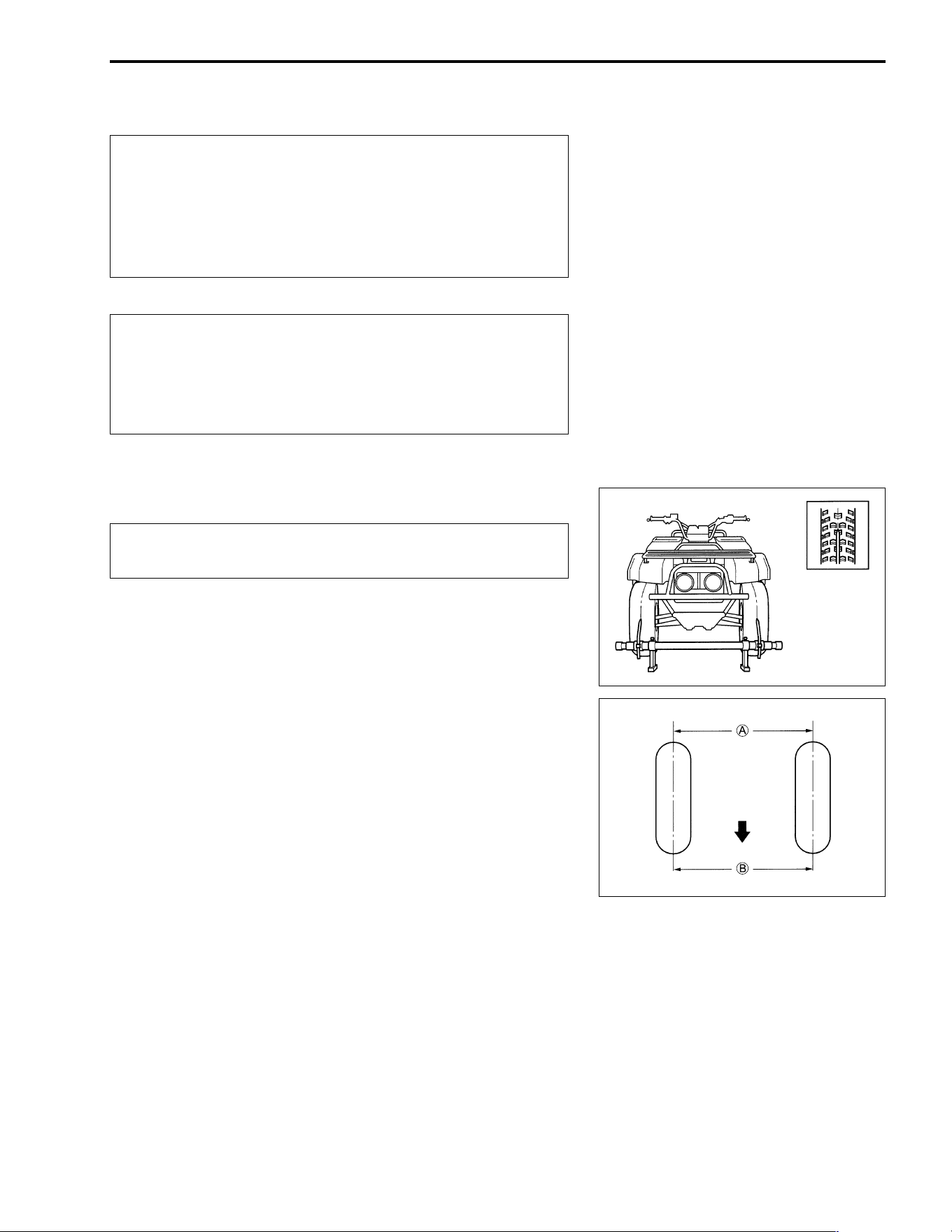
TOE-IN
• Place the vehicle on level ground.
• Make sure the tire pressure for right and left tires is the same
and set to the proper specification.
• Set the front wheels in the straight position.
• Place a load of 75 kg (165 lbs) on the seat.
• Measure the distance
A and
B of the front wheels with a
toe-in gauge as shown and calculate the difference between
A and
B.
$ Toe-in: 7 ± 4 mm (0.30 ± 0.16 in)
• If the toe-in is out of specification, bring it into the specified
range. ("7-48)
To minimize the possiblility of tire damage from
over-inflation, we strongly recommended that a man-
ual type air pump be used rather than a high pressure
air compressor as found in service stations. When fill-
ing air into the tires, never exceed 70 kPa (0.7 kgf/cm²,
10 psi).
The standard tire fitted on this vehicle is an
AT25×8-12✩✩
✩✩ ✩✩
✩✩ for the front and a AT25×10-12✩✩
✩✩ ✩✩
✩✩ for
the rear. The use of tires other than those specified
may cause instability. It is highly recommended to use
the specified tires.
Inspect initially at 200 km (100 miles, 1 month) and
every 1 000 km (600 miles, 3 months) thereafter.
Forward
A
B
2-20 PERIODIC MAINTENANCE
]
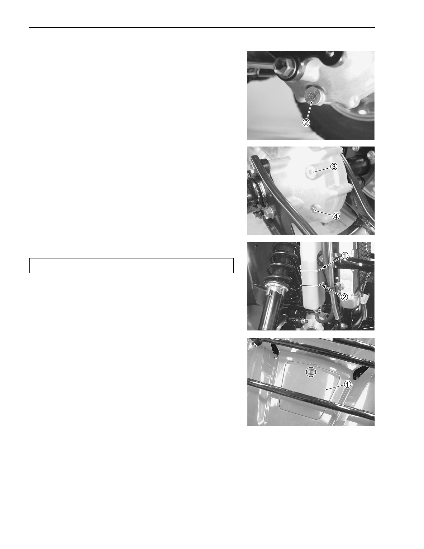
SUSPENSIONS
• Support the vehicle using a jack and wooden blocks.
• Remove the front and rear wheels. ("7-11)
• Inspect the suspension arm and bushing for scratches, wear,
or damage. If any damages are found, replace the suspen-
sion arm or bushing with a new one. ("7-35)
• Inspect the swinging arm, rear axle and bearing for scratches,
wear or damage. If any damages are found, replace them with
a new one. ("7-66)
• Inspect the front and rear shock absorbers for oil leakage or
damage. If any damages are found, replace them with a new
one. ("7-35 and 7-66)
Inspect every 2 000 km (1 200 miles, 6 months).

PERIODIC MAINTENANCE 2-21
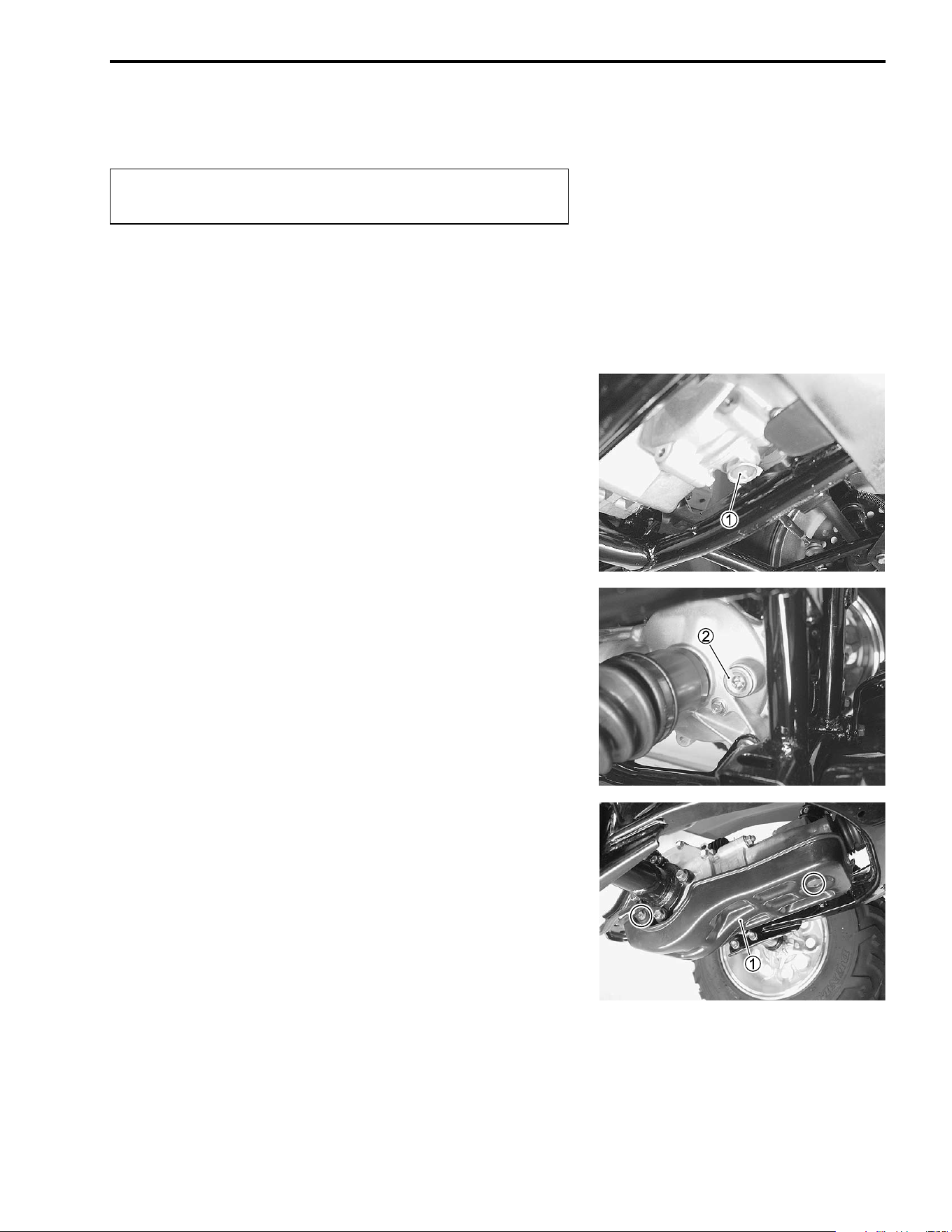
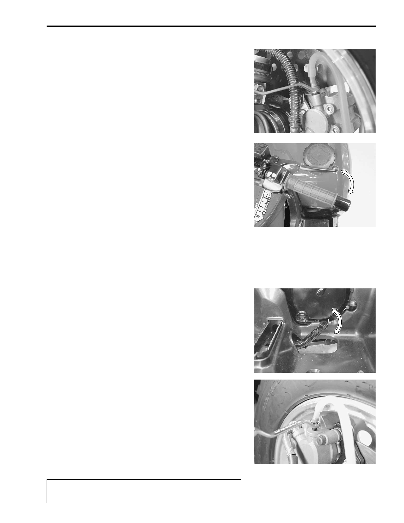
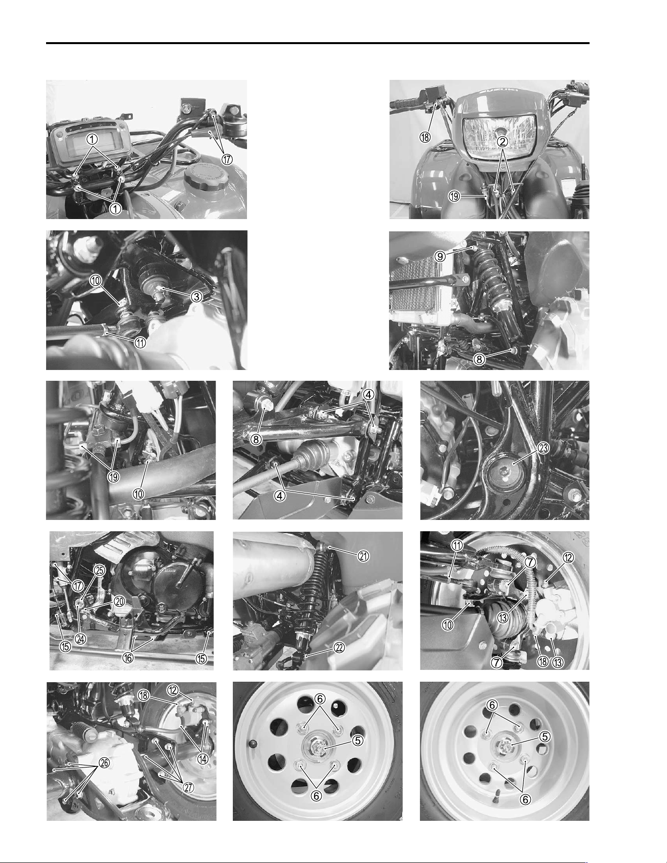
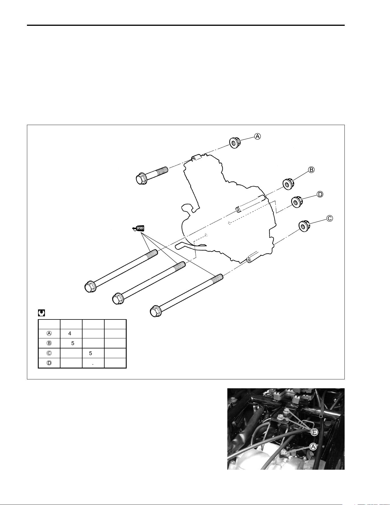
CHASSIS NUTS AND BOLTS
Check that all chassis nuts and bolts are tightened to their specified torque. (Refer to page 2-22 for the loca-
tions of the following nuts and bolts.)
Tighten initially at 200 km (100 miles, 1 month) and
every 1 000 km (600 miles, 3 months) thereafter.
Item N·m kgf-m lb-ft
1 Handlebar clamp bolt 23 2.3 16.5
2 Steering shaft holder bolt 23 2.3 16.5
3 Steering shaft lower nut 49 4.9 35.5
4 Wishbone arm pivot nut (upper and lower) 65 6.5 47.0
5 Hub nut (front and rear) 110 11.0 79.5
6 Wheel set nut (front and rear) 50 5.0 36.0
7 Steering knuckle pinch bolt (upper and lower) 50 5.0 36.0
8 Front shock absorber mounting nut (lower) 60 6.0 43.5
9 Front shock absorber mounting bolt (upper) 55 5.5 40.0
0 Tie rod end nut 60 6.0 43.5
A Tie rod locknut 29 2.9 21.0
B Brake air bleeder valve (front and rear) 7.5 0.75 5.5
C Brake caliper mounting bolt (front) 26 2.6 19.0
D Brake caliper mounting bolt (rear) 32 3.2 23.0
E Footrest bolt (M8) 26 2.6 19.0
F Footrest bolt (M10) 55 5.5 40.0
G Brake master cylinder mounting bolt (front and rear) 10 1.0 7.0
H Brake hose union bolt (front and rear) 23 2.3 16.5
I Front brake pipe nut 16 1.6 11.5
J Brake pedal bolt 26 2.6 19.0
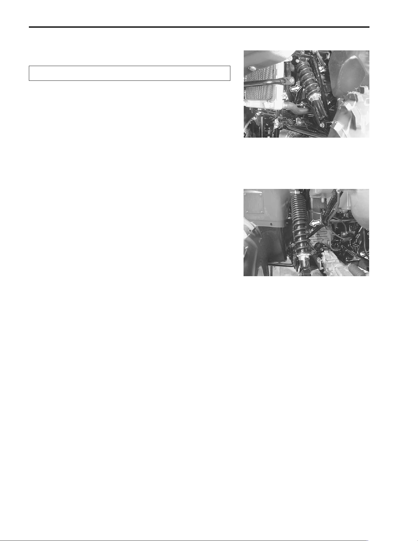
K Rear shock absorber mounting nut (upper) 35 3.5 25.5
L Rear shock absorber mounting bolt (lower) 60 6.0 43.5
M Rear swingarm pivot bolt (left) 100 10.0 72.5
N Rear swingarm pivot bolt (right) 9.5 0.95 7.0
O Rear swingarm pivot locknut (right) 100 10.0 72.5
P Rear axle housing bolt 55 5.5 40.0
Q Axle housing mounting nut 60 6.0 43.5
2-22 PERIODIC MAINTENANCE
PERIODIC MAINTENANCE 2-23
GENERAL LUBRICATION
Proper lubrication is important for smooth operation and long life of each working part of the vehicle.
Major lubrication points are indicated below.
1
Steering shaft holder
5
Drive shaft joint spline
&
Grease
2
Brake lever holder and throttle lever
6
Throttle cable
*
Motor oil
3
Brake pedal
7
Starter cable
4
Propeller shaft joint spline
NOTE:
* Before lubricating each part, remove any rust and wipe off any grease, oil, dirt, or grime.
* Lubricate exposed parts which are subject to rust, with a rust preventative spray, especially whenever the
vehicle has been operated under wet or rainy conditions.
Lubricate every 1000 km (600 miles, 3 months).
2-24 PERIODIC MAINTENANCE
COMPRESSION PRESSURE CHECK
The compression pressure reading of a cylinder is a good indicator of its internal condition.
The decision to overhaul the cylinder is often based on the results of a compression test. Periodic mainte-
nance records kept at your dealership shoud include compression readings for each maintenance service.
$ Compression pressure:
Standard: 1 000 kPa (10.0 kgf/cm², 142 psi)
Service Limit: 800 kPa (8.0 kgf/cm², 114 psi)
(Automatic decompression actuated)
Low compression pressure can indicate any of the following conditions:
* Excessively worn cylinder walls
* Worn piston or piston rings
* Piston rings stuck in grooves
* Poor valve seating
* Ruptured or otherwise defective cylinder head gasket
NOTE:
When the compression pressure goes below specification, check the engine for conditions listed above.
COMPRESSION TEST PROCEDURE
NOTE:
* Before testing the engine for compression pressure, make
sure that the cylinder head nuts are tightened to the specified
torque values and the valves are properly adjusted.
* Warm up the engine before testing.
* Make sure that the battery is fully charged.
Remove the related parts and test the compression pressure in
the following manner.
• Remove the spark plug. ("2-6)
• Install the compression gauge and adaptor in the spark plug
hole. Make sure that the connection is tight.
• Keep the throttle lever in the fully open position.
• Press the starter button and crank the engine for a few sec-
onds. Record the maximum gauge reading as the cylinder
compression.
% 09915-64512: Compression gauge set
09915-63310: Adaptor
PERIODIC MAINTENANCE 2-25
OIL PRESSURE CHECK
Check the engine oil pressure periodically. This will give a good indication of the condition of the moving
parts.
$ Oil pressure:
Low or high oil pressure can indicate any of the following conditions:
LOW OIL PRESSURE
* Clogged oil filter
* Oil leakage from the oil passage
* Damaged O-ring
* Defective oil pump
* Combination of the above items
HIGH OIL PRESSURE
* Engine oil viscosity is too high
* Clogged oil passage
* Combination of the above items
OIL PRESSURE TEST PROCEDURE
• Connect the tachometer onto the spark plug high-tension
cord.
• Remove the right mud guard. ("7-8)
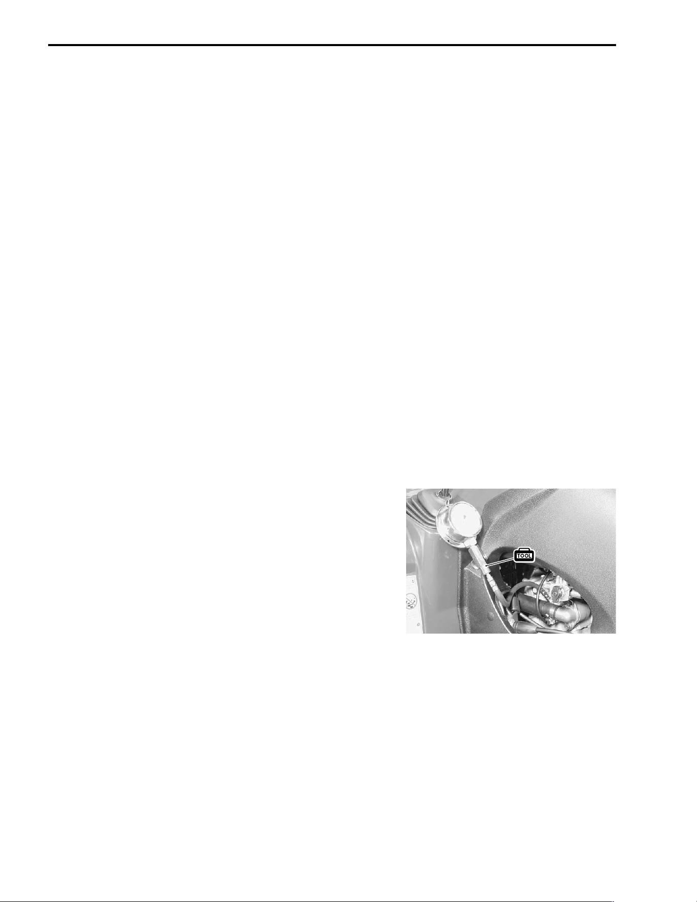
• Remove the main oil gallery plug
1.
• Install the oil pressure gauge and adaptor into the main oil
gallery.
• Warm up the engine as follows:
Summer: 10 minutes at 2 000 r/min
Winter: 20 minutes at 2 000 r/min
• After warming up the engine, increase the engine speed to
3 000 r/min (observe the tachometer), and read the oil press-
rure gauge.
% 09915-74511: Oil pressure gauge
09900-26006: Tachometer
# Main oil gallery plug: 23 N·m (2.3 kgf-m, 16.5 lb-ft)
Above 120 kPa (1.2 kgf/cm², 17.0 psi)
Below 160 kPa (1.6 kgf/cm², 23.0 psi)
at 3 000 r/min, Oil temp. at 60°C (140°F)

2-26 PERIODIC MAINTENANCE
INITIAL ENGAGEMENT AND CLUTCH LOCK-UP INSPECTION
The LT-F500F is equipped with a centrifugal type automatic
clutch.
To insure proper performance and longevity of the clutch
assemblies it is essential that the clutches engage smoothly and
gradually. Before checking the initial engagement and clutch
lock-up two inspection checks must be performed to thoroughly
check the operation of the drive train. Perform the following:
• Warm up the engine.
INITIAL ENGAGEMENT INSPECTION
• Connect the tachometer or the multi circuit tester onto the
spark plug high-tension cord.
• Start the engine.
• Shift the range lever to the “High” position.
• Slowly open the throttle and note the engine speed (r/min)
when the vehicle begins to move forward.
% 09900-26006: Tachometer, or
09900-25008: Multi circuit tester set
$ Engagement speed: 1 500 – 1 900 r/min
If the engagement speed does not coincide with the standard
range, inspect the following items for any abnormalities.
* Clutch shoes . . . . . . . . . . . . . . . . . . . . . . . . "3-19, 3-43, 3-89
* Clutch shoe wheel. . . . . . . . . . . . . . . . . . . . "3-19, 3-43, 3-89
PERIODIC MAINTENANCE 2-27
CLUTCH LOCK-UP INSPECTION
Perform this inspection to determine if the clutch is engaging
fully and not slipping.
• Connect a tachometer onto the spark plug high-tension code.
• Start the engine.
• Shift the range lever to the “High” position.
• Apply the front and rear brakes as firmly as possible.
• Fully open the throttle for two seconds and note the maximum
engine speed sustained during the test cycle.
$ Lock-up speed: 3 400 – 4 000 r/min
!
If the lock-up speed (r/min) does not coincide with the standard
range, inspect the following items for any abnormalities.
* Clutch shoes . . . . . . . . . . . . . . . . . . . . . . . . "3-43
* Clutch wheel . . . . . . . . . . . . . . . . . . . . . . . . "3-43
Do not apply full power for more than 5 seconds or
damage to the clutch or engine may occur.
2-28 PERIODIC MAINTENANCE
PARKING INSPECTION
Depress the rear brake pedal and shift the shift lever
1 into “P”
(Parking). Inspect the rear wheel for locking by moving the vehi-
cle back and forth.
If the rear wheel is unlocked, inspect the rear drive. ("4-28)
If it is unable to shift into “P”, adjust the parking interlock cable.
("7-83)

3
6
ENGINE 3-1
CONTENTS
ENGINE
ENGINE COMPONENTS REMOVABLE WITH ENGINE IN PLACE ...3- 2
ENGINE LEFT SIDE .....................................................................3- 2
ENGINE RIGHT SIDE ..................................................................3- 2
ENGINE CENTER ........................................................................3- 2
ENGINE REMOVAL AND INSTALLATION .........................................3- 3
ENGINE REMOVAL .....................................................................3- 3
ENGINE INSTALLATION .............................................................3- 8
ENGINE DISASSEMBLY .....................................................................3-12
ENGINE TOP SIDE ......................................................................3-12
ENGINE BOTTOM SIDE ..............................................................3-16
ENGINE COMPONENTS INSPECTION AND SERVICING .................3-25
CYLINDER HEAD COVER ..........................................................3-25
CYLINDER HEAD ........................................................................3-26
CAMSHAFT ..................................................................................3-36
CAM CHAIN TENSION ADJUSTER ............................................3-38
CYLINDER ...................................................................................3-38
PISTON ........................................................................................3-39
CONROD/CRANKSHAFT ............................................................3-41
CLUTCH .......................................................................................3-42
TRANSMISSION ..........................................................................3-45
GEARSHIFT FORK ......................................................................3-48
TRANSFER GEARSHIFT CAM ...................................................3-49
OIL PUMP ....................................................................................3-51
CRANKCASE ...............................................................................3-51
GENERATOR COVER .................................................................3-56
CLUTCH COVER .........................................................................3-60
RECOIL STARTER ......................................................................3-61
DRIVE TRAIN (INBOARD SIDE) .................................................3-64
SHIM ADJUSTMENT ...................................................................3-73
REASSEMBLY INFORMATION ..................................................3-76
CRANKSHAFT .............................................................................3-77
ENGINE REASSEMBLY ......................................................................3-78
ENGINE BOTTOM SIDE ..............................................................3-78
GEARSHIFT CAM AND FORK ....................................................3-79
TRANSFER ..................................................................................3-92
ENGINE TOP SIDE ......................................................................3-99

3-2 ENGINE
ENGINE COMPONENTS REMOVABLE WITH ENGINE IN PLACE
The parts listed below can be removed and installed without removing the engine from the frame. Refer to
the page listed in each section for removal and installation instructions.
ENGINE LEFT SIDE
ENGINE RIGHT SIDE
ENGINE CENTER
PARTS REMOVAL INSTALLATION
Recoil starter 3-13 3-106
Starter cup 3-16 3-97
Speedometer gearbox 3-16 3-98
Transfer gears 3-17 3-95
Neutral switch 3-18 3-84
Generator 3-22 3-84
PARTS REMOVAL INSTALLATION
Clutch cover 3-18 3-91
Clutch 3-19 3-87
Cam chain 3-20 3-85
Gearshift 3-20 3-85
Gearshift cam stopper 3-21 3-52
Oil pump drive gear 3-21 3-85
Oil pump 3-21 3-84
PARTS REMOVAL INSTALLATION
Starter motor 3-4 3-11
Cam chain tension adjuster 3-12 3-105
Cylinder head cover 3-13 3-103
Camshaft 3-13 3-102
Cylinder head 3-14 3-101
Cylinder 3-15 3-100
Piston 3-16 3-99
Oil sump filter 3-51 3-51
ENGINE 3-3
ENGINE REMOVAL AND INSTALLATION
ENGINE REMOVAL
Before taking the engine out of the frame, wash the engine
using a steam cleaner. Engine removal is sequentially explained
in the following steps. Reinstall the engine by reversing the
removal procedure.
• Drain engine oil. (!2-9)
• Drain engine coolant. (!2-12)
• Remove the seat. (!7-4)
• Disconnect the battery lead wires.
• Remove the battery.
"
• Remove the fuel tank covers. (!7-5)
• Remove the mud guard. (L&R) (!7-8)
• Remove the rear carrier and rear fender. (!7-8 and 7-9)
• Remove the fuel tank. (!5-3)
• Remove the right inner fender. (!7-6)
• Disconnect the water hoses.
When disconnecting the lead wires, be sure to discon-
nect the
- battery lead wire first.
3-4 ENGINE
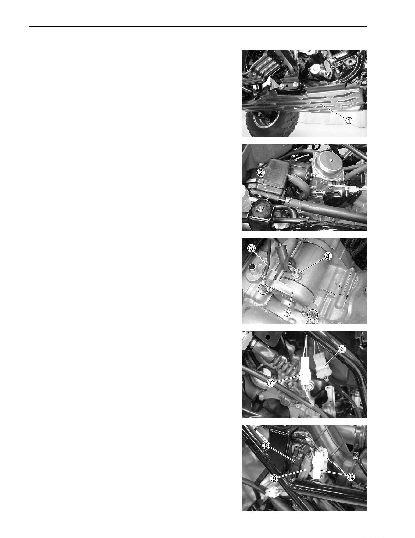
• Remove the engine under cover
1.
• Remove the carburetor. (!5-8)
• Disconnect the breather hose
2 that connects the oil retun
tank and the engine.
• Disconnect the engine ground lead wire
3 and starter motor
lead wire
4.
• Remove the starter motor
5.
• Disconnect the speed sensor lead wire coupler
6.
• Disconnect the gearshift lever lead wire coupler
7.
• Disconnect the generator lead wire coupler
8 and signal gen-
erator lead wire coupler
9.
• Disconnect the neutral switch lead wire couplers
0.
ENGINE 3-5
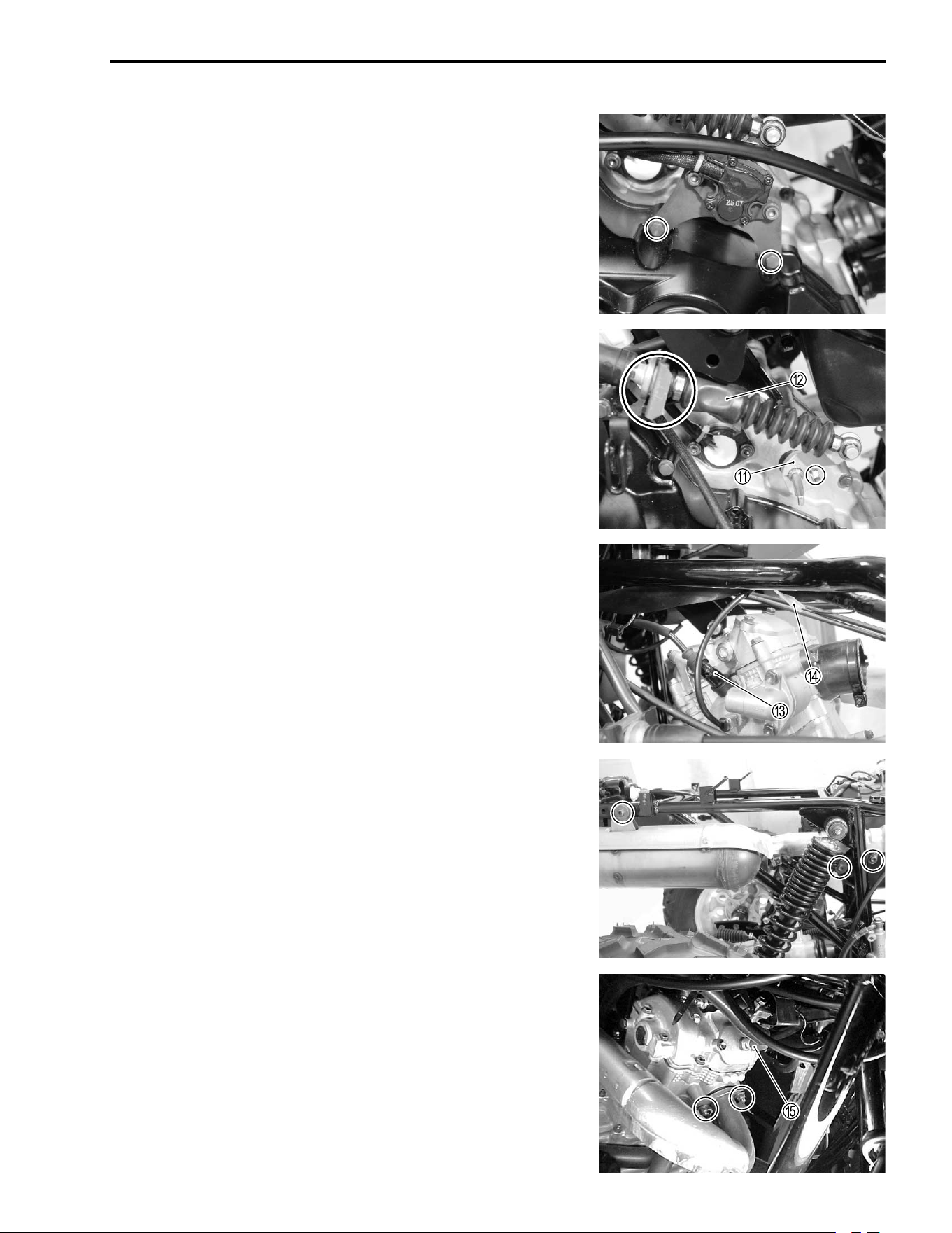
• Remove the reverse switch.
• Disconnect the gearshift arm
A and reverse gear cable
B.
• Disconnect the spark plug cap
C.
• Disconnect the engine coolant temperature switch lead wire
D.
• Remove the muffler.
• Remove the exhaust pipe.
• Disconnect the breather hose
E.
3-6 ENGINE
• Remove the right footrest.
• Remove the brake pedal.
• Remove the propeller shaft flange coupling bolts, front and
rear.
ENGINE 3-7
• Remove the engine mounting bolts and nuts.
• Remove the engine mounting bracket
A.
• Remove the engine from the right side.
3-8 ENGINE
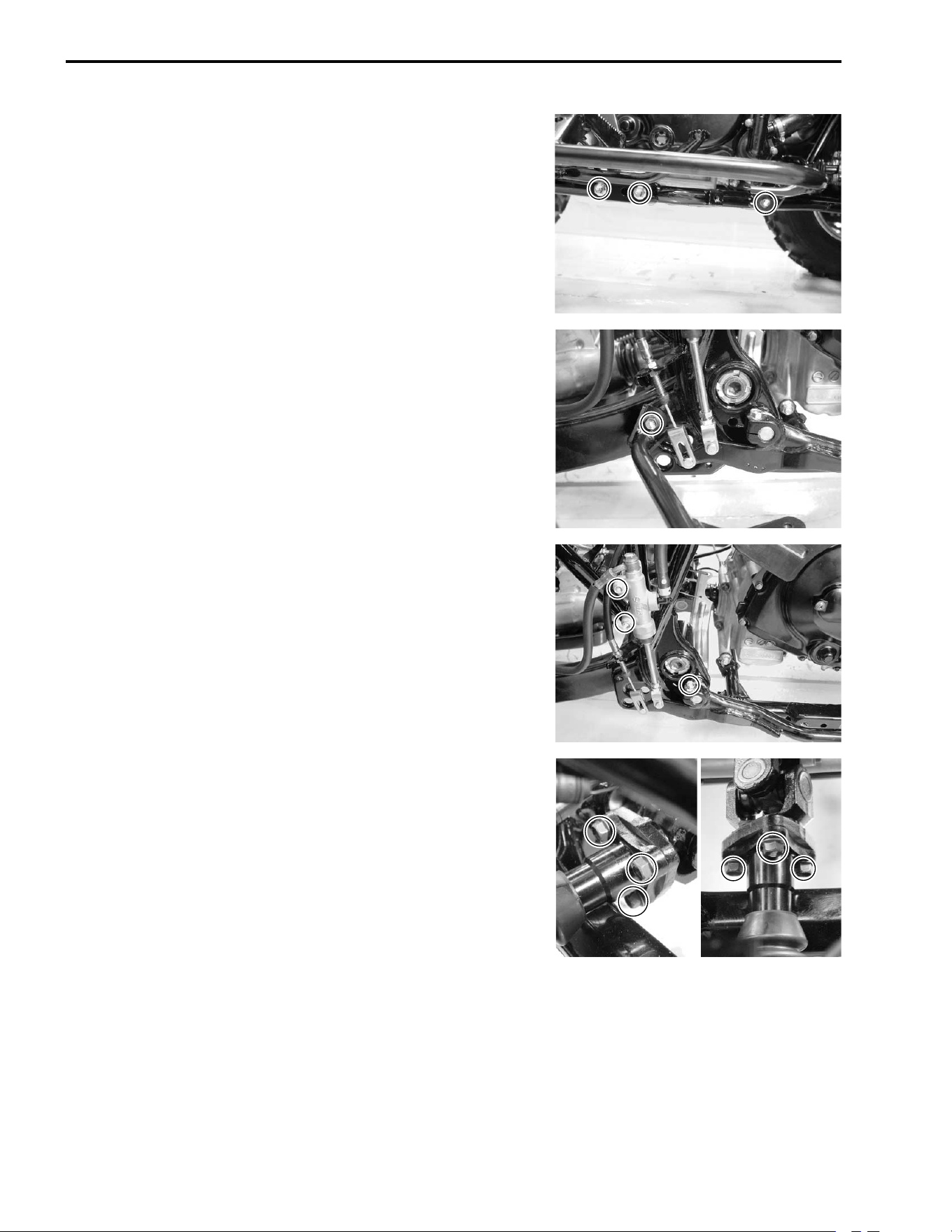
ENGINE INSTALLATION
Remount the engine in the reverse order of engine removal.
Pay attention to the following points:
NOTE:
* The engine mounting nuts are self-locking.
* Once the nut has been removed, it is no longer of any use. Be
sure to use new nuts, and then tighten them to the specified
torque.
• Tighten the bolts
E to the specified torque.
# Engine mounting bracket bolt:
26 N·m (2.6 kgf-m, 19.0 lb-ft)
ITEM N·m kgf-m lb-ft
A
40 4.0 29.0
B
55 5.5 40.0
C
55 5.5 40.0
D
55 5.5 40.0
@
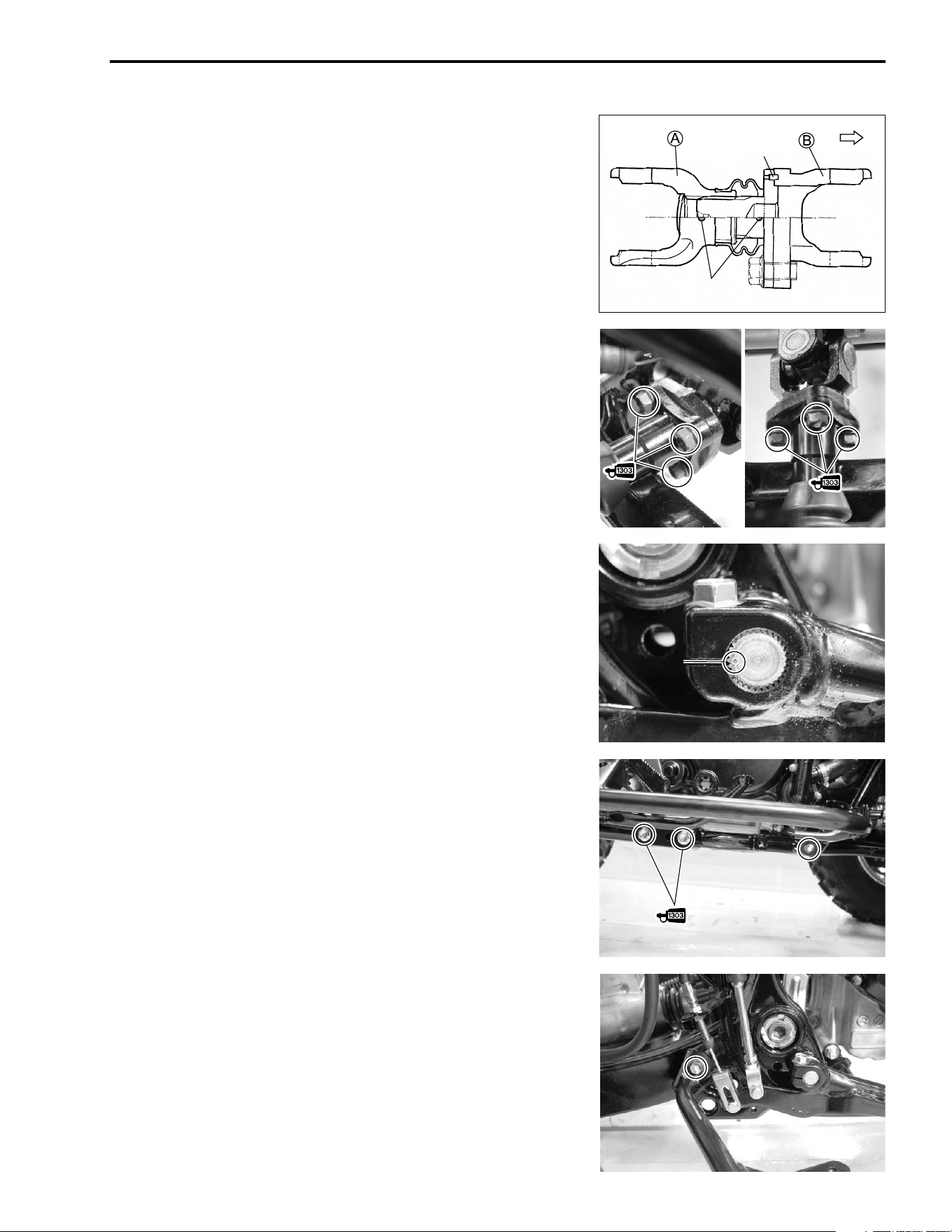
ENGINE 3-9
• Install the propeller shaft, front and rear.
NOTE:
Align the match marks on the front propeller shaft so that the
yoke
A would be aligned with the yoke
B as shown in illustra-
tion.
• Apply THREAD LOCK SUPER “1303” to the propeller shaft
flange coupling bolts and tighten them to the specified torque.
$ 99000-32030: THREAD LOCK SUPER “1303”
# Front propeller shaft flange coupling bolt:
45 N·m (4.5 kgf-m, 32.5 lb-ft)
Rear propeller shaft flange coupling bolt:
30 N·m (3.0 kgf-m, 21.5 lb-ft)
• Install the brake pedal by aligning the punched mark on the
shaft with the slit of the pedal.
• Apply THREAD LOCK SUPER “1303” to the bolts (M10 only)
and tighten them to the specified torque.
$ 99000-32030: THREAD LOCK SUPER “1303”
# Footrest bolt: 8 mm: 26 N·m (2.6 kgf-m, 19.0 lb-ft)
10 mm: 55 N·m (5.5 kgf-m, 40.0 lb-ft)
Pin
Match mark
FRONT
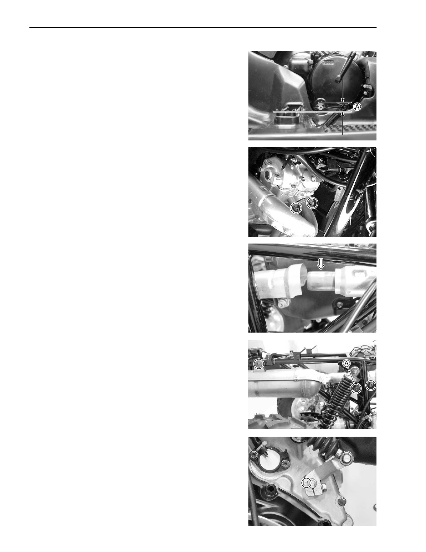
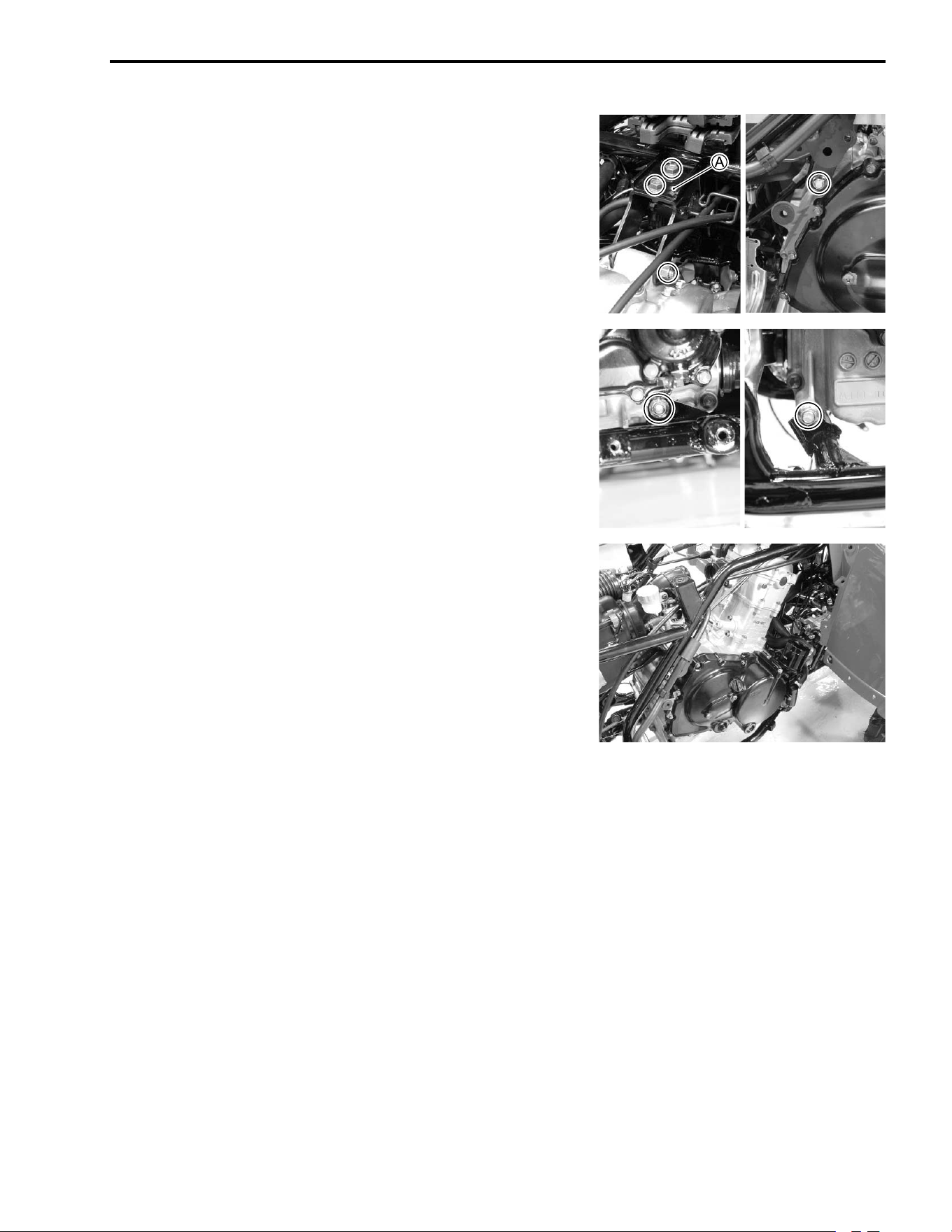
3-10 ENGINE
• Adjust the brake pedal height as shown.
% Brake pedal height
A
Standard: 5 – 15 mm (0.2 – 0.6 in)
Brake pedal (!2-15)
• Install the new gasket and tighten the exhaust pipe nuts tem-
porally.
• Apply gas sealer to the exhaust pipe connector.
EXHAUST GAS SEALER: PERMATEX 1372
• Apply THREAD LOCK “1342” to the muffler mounting bolt
A.
• Tighten the muffler mounting bolts and exhaust pipe bolts to
the specified torque.
& 99000-32050: THREAD LOCK “1342”
# Muffler connecting bolt: 23 N·m (2.3 kgf-m, 16.5 lb-ft)
Muffler mounting bolt: 23 N·m (2.3 kgf-m, 16.5 lb-ft)
Exhaust pipe nut: 23 N·m (2.3 kgf-m, 16.5 lb-ft)
• Install the gearshift arm.
NOTE:
Align the no teeth position on the gearshift arm with the no teeth
position on the reverse shift shaft.
ENGINE 3-11
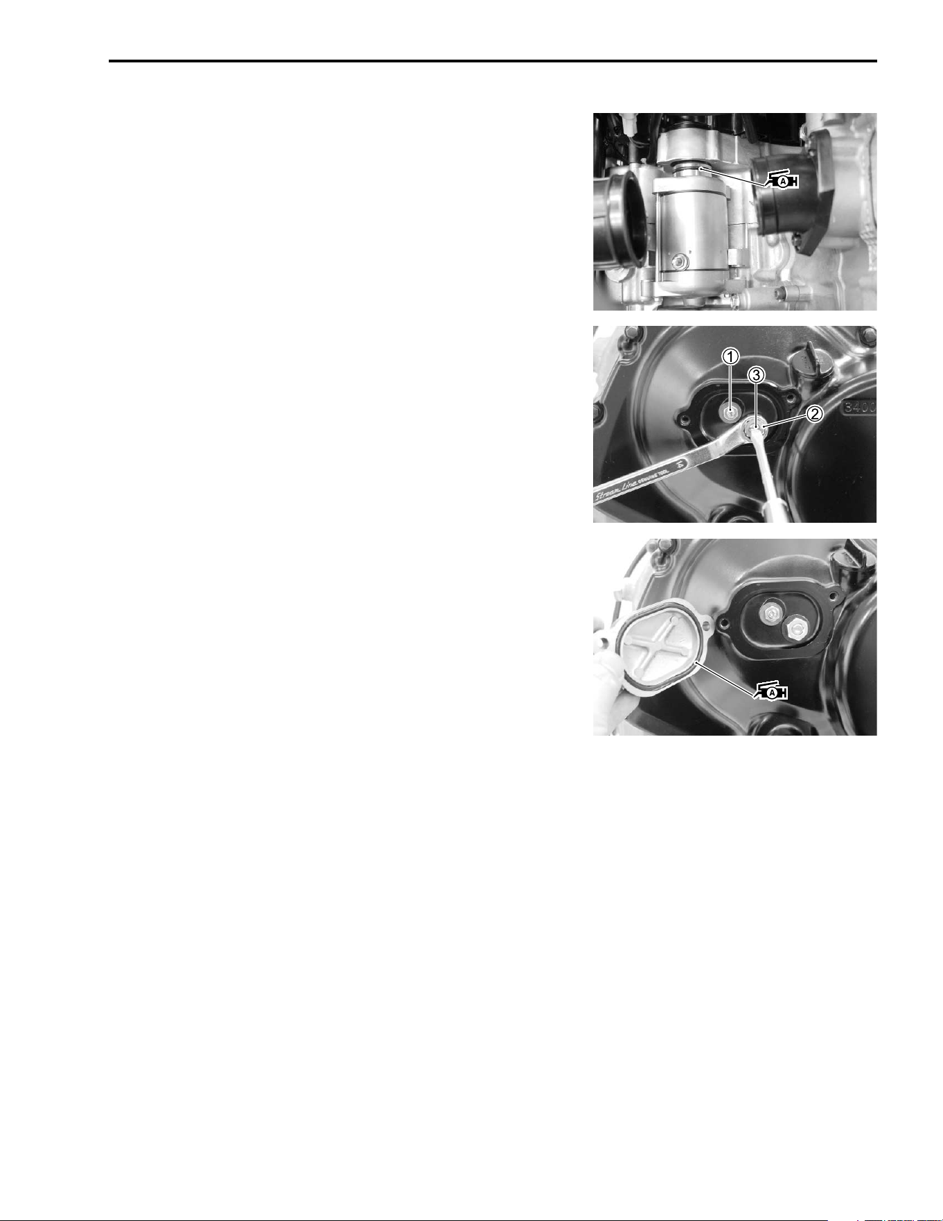
STARTER MOTOR
• Install the starter motor.
NOTE:
Apply grease to the new O-ring.
' 99000-25030: SUZUKI SUPER GREASE “A” (USA)
99000-25010: SUZUKI SUPER GREASE “A” (Others)
• Loosen the locknuts
1 and
2.
• Rotate the adjusting screw
3 counterclockwise until it stops.
• Tighten the locknut
1.
• Rotate the adjusting screw
3 clockwise 1/4 – 2/4 turn back.
• Tighten the locknut
2 by holding the adjuster screw
3.
# Locknut
1: 8 N·m (0.8 kgf-m, 5.7 lb-ft)
Locknut
2: 23 N·m (2.3 kgf-m, 16.5 lb-ft)
• Apply SUZUKI SUPER GREASE “A” to the O-ring and install
the clutch adjuster cap.
' 99000-25030: SUZUKI SUPER GREASE “A” (USA)
99000-25010: SUZUKI SUPER GREASE “A” (Others)
• After installing the engine, route the wire harness, cables and
hoses properly. (!9-12)
• Adjust the following items.
* Engine oil !2-9
* Engine coolant !2-12
* Engine idle speed !2-8
* Throttle cable play !2-8
% Engine oil capacity
Oil change: 2.5 L (2.6/2.2 US/lmp qt)
Oil and filter change: 2.7 L (2.9/2.4 US/lmp qt)
Engine overhaul: 3.2 L (3.4/2.8 US/lmp qt)
3-12 ENGINE
ENGINE DISASSEMBLY
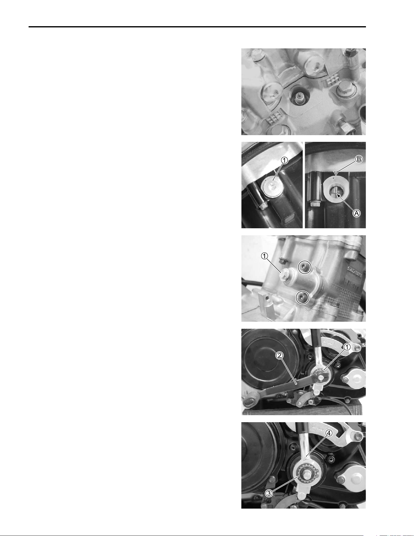
ENGINE TOP SIDE
SPARK PLUG
• Remove the spark plug.
( 09930-10121: Spark plug wrench set
• Remove the valve timing inspection plug
1.
• Turn the crankshaft and align the “TDC” line
A on the genera-
tor rotor with the index mark
B on the crankcase.
CAM CHAIN TENSION ADJUSTER
• After removing the spring holder bolt
1, remove the cam
chain tension adjuster.
GEARSHIFT LEVER
• Remove the gearshift lever bolt
1, then remove the gearshift
lever
2.
• Remove the shift lever snapring
3 and shift lever assembly
4.
ENGINE 3-13
• Remove the gear position switch.
RECOIL STARTER
• Remove the recoil starter.
CYLINDER HEAD COVER
• Remove the valve inspection caps.
• Remove the cylinder head cover.
CAMSHAFT
• Remove the camshaft end cap
1.
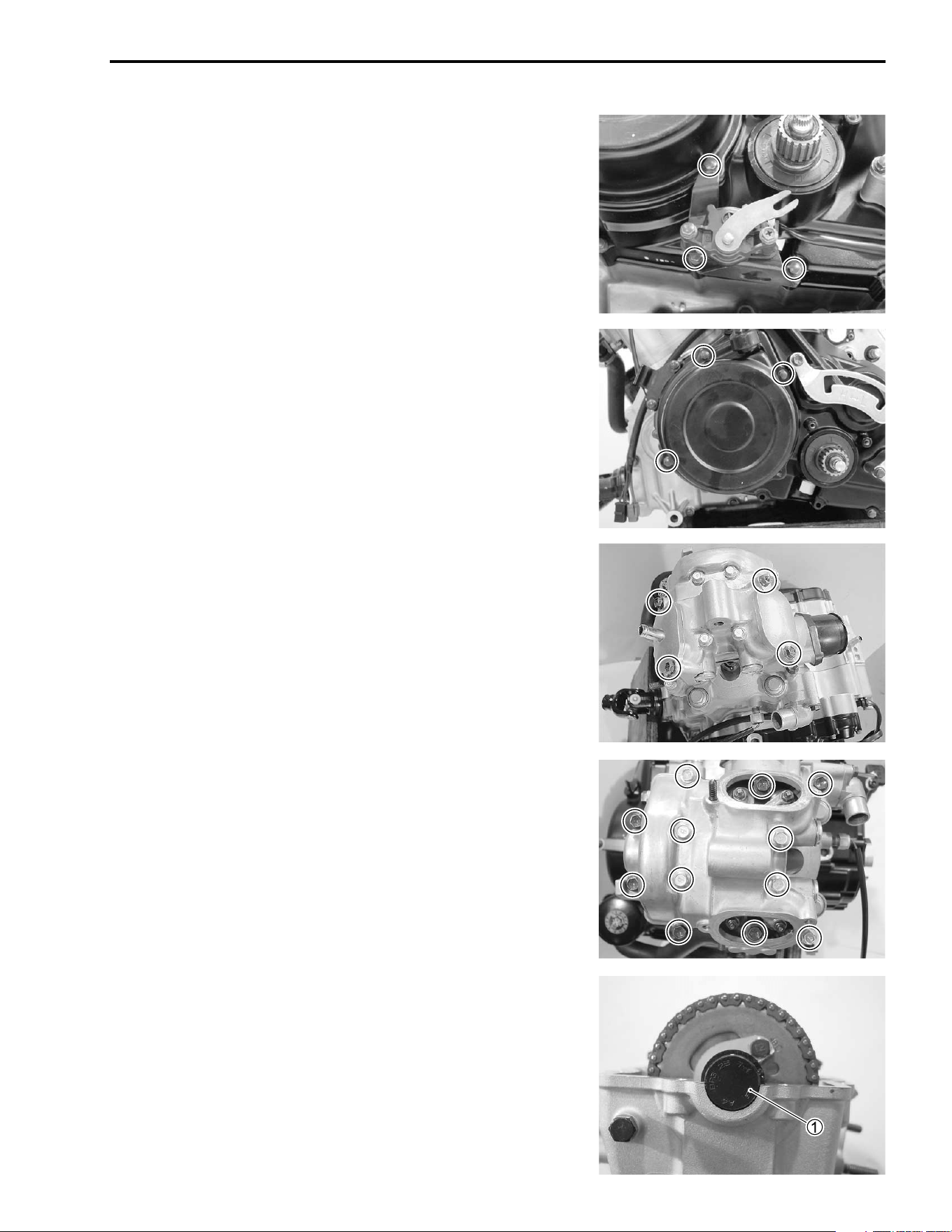
3-14 ENGINE
• Flatten the lock washer.
• Remove the cam chain sprocket bolts and lock washer.
• Remove the camshaft
1 and camshaft sprocket
2.
"
• Remove the C-ring
4.
"
CYLINDER HEAD
• Remove the cylinder head nuts.
Do not drop the cam chain
3 into the crankcase.
Do not drop the C-ring
4 into the crankcase.
ENGINE 3-15
• Remove the cylinder head bolts diagonally.
• Remove the cylinder head.
NOTE:
If the cylinder head does not come off, lightly tap it with a plastic
hammer.
• Remove the dowel pins and gasket
1.
CYLINDER
• Remove the cam chain guide
1.
• Remove the radiator hose
2.
• Remove the cylinder nuts.
• Remove the cylinder.
NOTE:
Be careful not to drop the dowel pins into the crankcase.
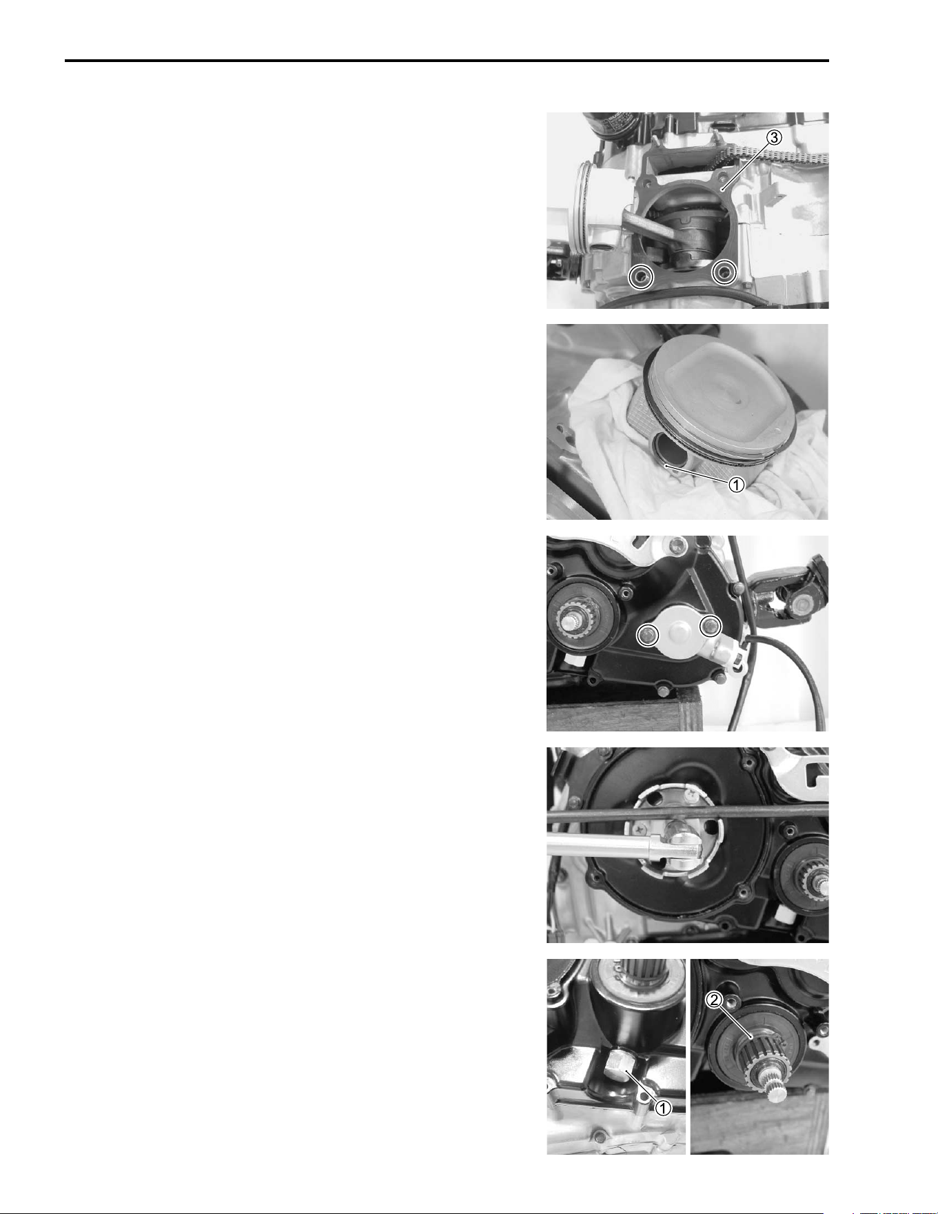
3-16 ENGINE
• Remove the dowel pins and gasket
3.
PISTON
• Remove the piston by removing the piston pin circlip
1.
NOTE:
Place a rag under the piston so as not to drop the piston pin cir-
clip into the crankcase.
ENGINE BOTTOM SIDE
SPEEDOMETER GEARBOX
• Remove the speedometer gearbox.
STARTER CUP
• Remove the starter cup nut by using a suitable bar.
• Remove the starter cup.
• Remove the transfer gearshift cam stopper
1.
• Remove the transfer gearshift shaft snap ring
2.
ENGINE 3-17
• Remove the generator rotor cover.
TRANSFER
• Remove the starter driven gear
1, the spacer
2, the starter
idle gear
3, the washer
4, the transfer idle gear
5, the
washer
6, the transfer No. 2 gear
7, the washer
8 and the
transfer output gear
9.
• Remove the starter driven gear shaft
0, the starter idle gear
shaft
A, the gear fork shaft
B, the gearshift fork
C, the
spacer and washer
D, the transfer selection dog
E, and the
transfer output gear spacer
F.
• Remove the snap ring
G, washer
H and the transfer No. 1
gear
I.
• Remove the bush
J and spacer
K.
• Remove the washer
L and the gearshift shaft
M.
3-18 ENGINE
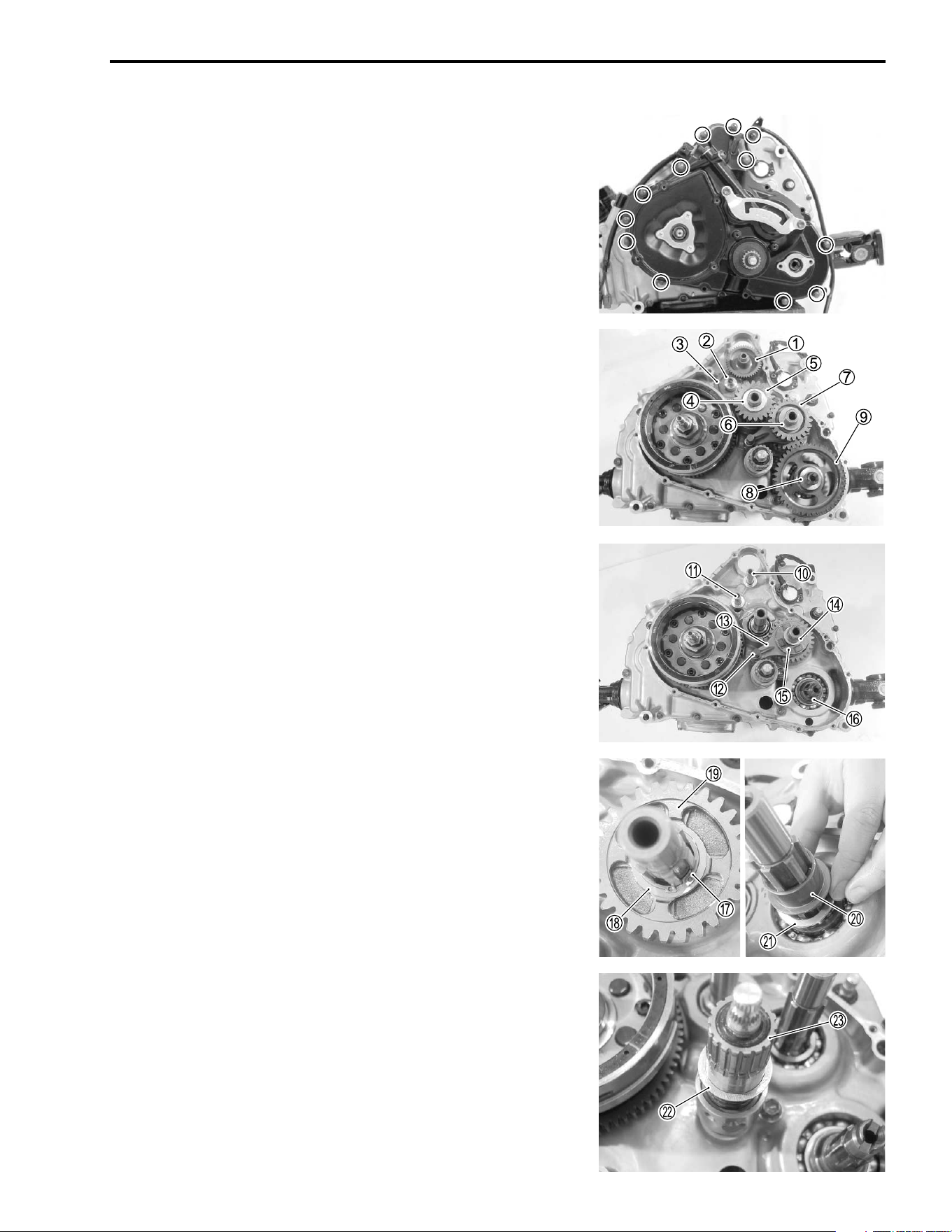
NEUTRAL SWITCH
• Remove the neutral switch.
• Remove the O-ring
1, spring
2 and pin
3.
CLUTCH COVER
• Remove the clutch adjuster cap.
• Remove the clutch cover.
• Remove the washer
1, clutch release arm
2 and clutch
release roller guide
3.
• Remove the water pump drive joint
4 and pin
5.
ENGINE 3-19
• Unlock the clutch shoe nut.
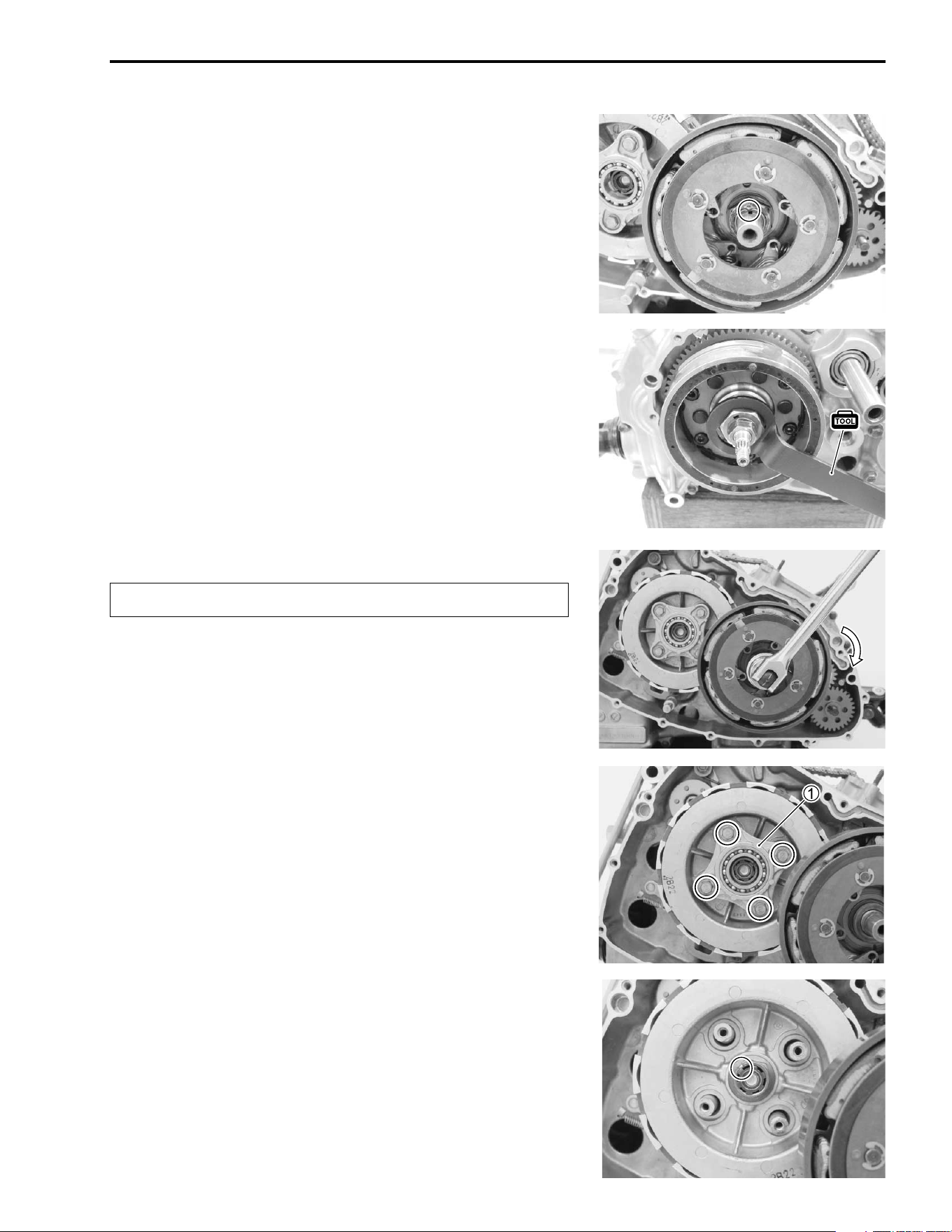
CLUTCH
• While holding the generator rotor with the special tool, remove
the clutch shoe nut.
( 09930-44541: Rotor holder
"
• Remove the clutch release plate
1.
• Remove the clutch springs.
• Unlock the clutch sleeve hub nut.
Clutch shoe nut has left-hand threads.
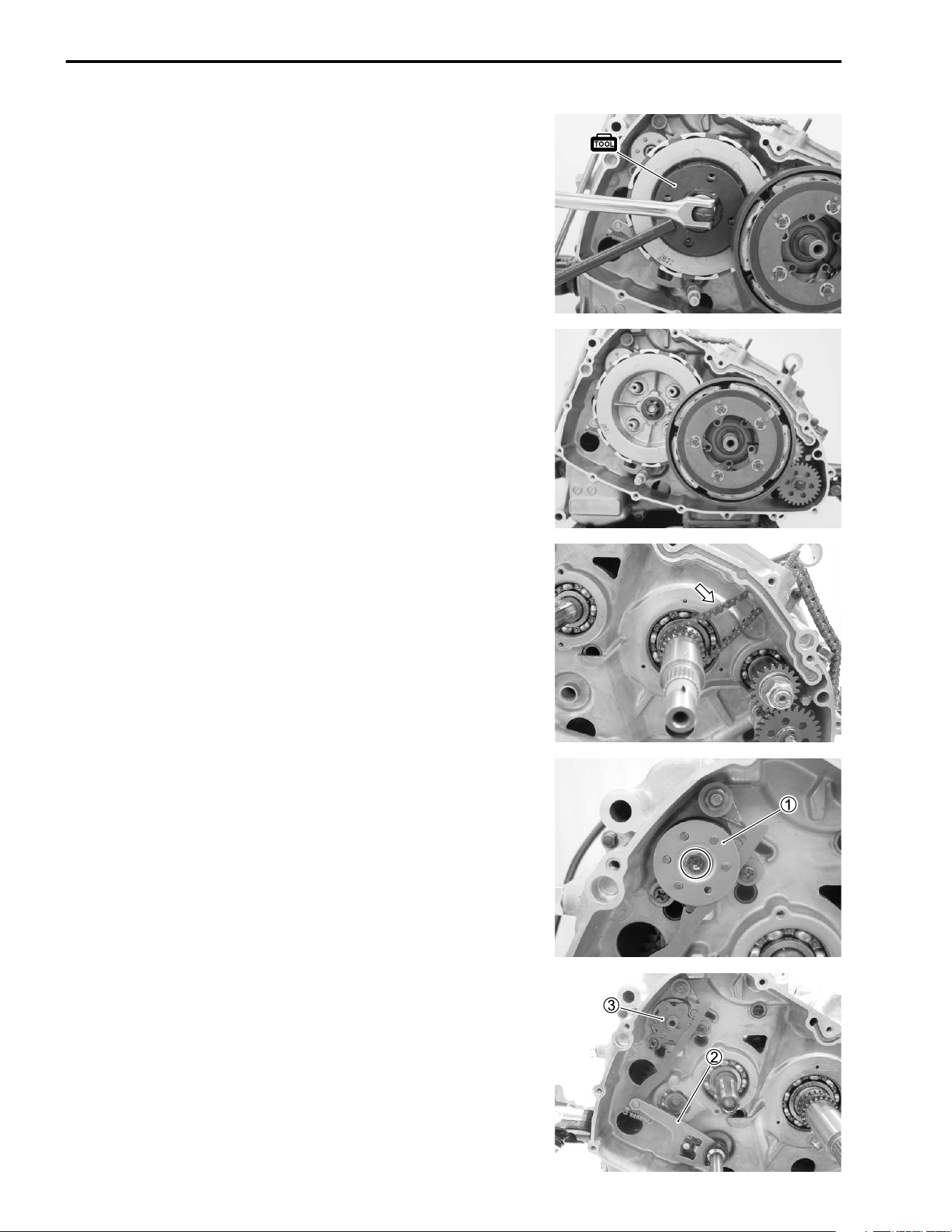
3-20 ENGINE
• Remove the clutch sleeve hub nut with the special tool.
( 09920-53730: Clutch sleeve hub holder
• Remove the clutch shoe assembly and primary driven gear
assembly.
CAM CHAIN
• Remove the cam chain.
GEARSHIFT
• Remove the gearshift cam plate guide
1.
• Remove the gearshift shaft
2 and gearshift cam plate
3.
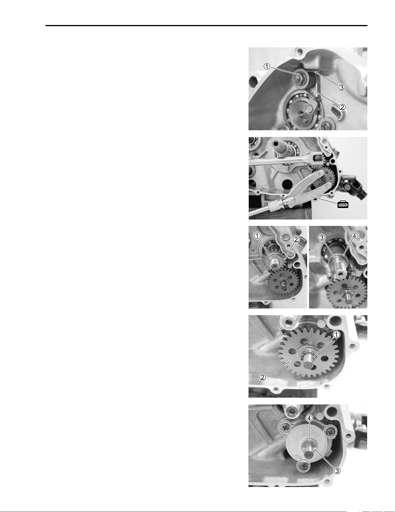
ENGINE 3-21
GEARSHIFT CAM STOPPER
• Remove the cam stopper nut
1, the gearshift cam stopper
2
and spring
3.
-
OIL PUMP DRIVE GEAR
• Remove the oil pump drive gear bolt by holding the oil pump
driven gear with the special tool.
( 09930-40113: Rotor holder
• Remove the washer
1 and oil pump drive gear
2.
• Remove the pin
3 and spacer
4.
OIL PUMP
• Remove the snap ring
1.
• Remove the oil pump driven gear
2.
• Remove the pin
3 and washer
4.
• Remove the oil pump.
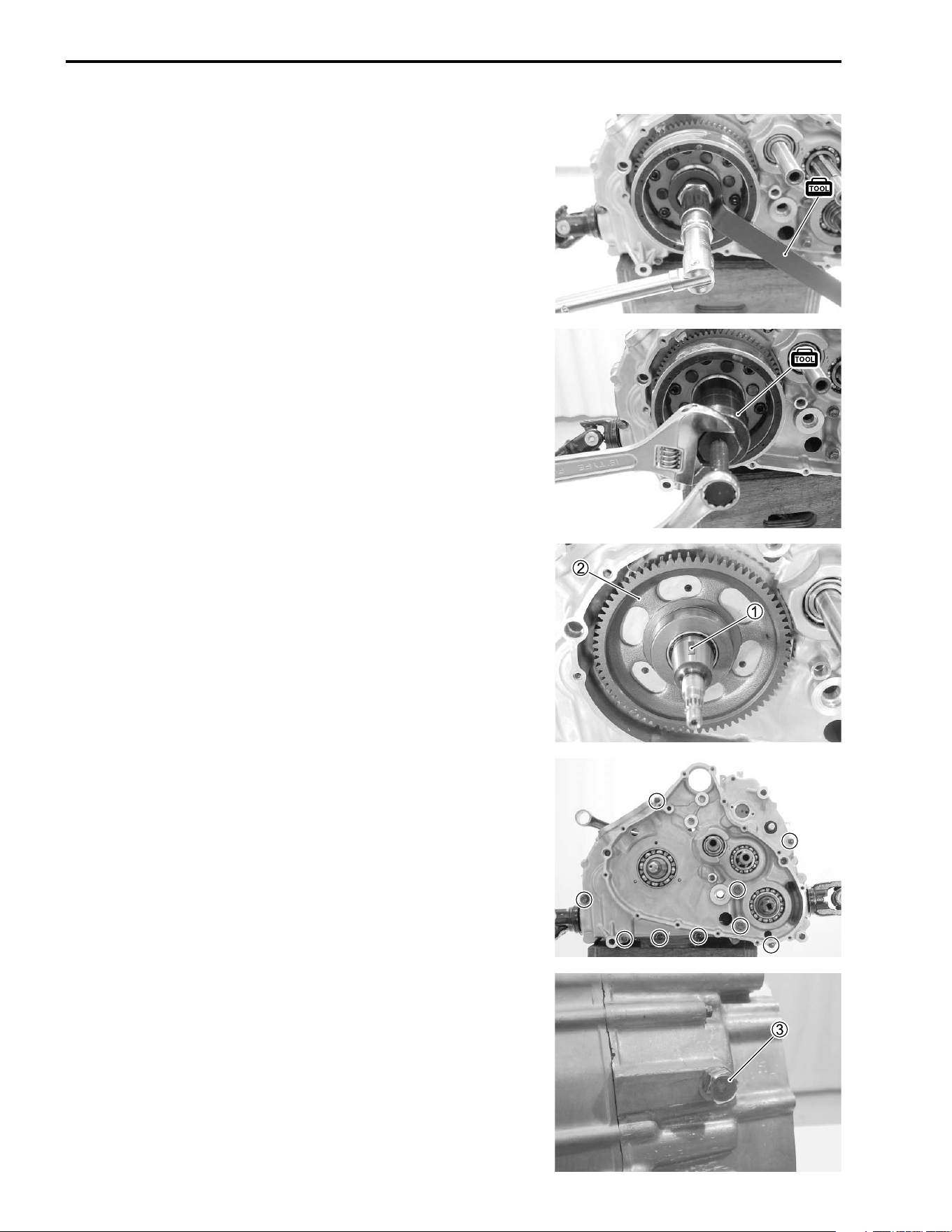
3-22 ENGINE
GENERATOR
• Remove the generator rotor bolt with the special tool.
( 09930-44541: Rotor holder
• Remove the generator rotor with the special tool.
( 09930-30721: Rotor remover
• Remove the key
1.
• Remove the starter driven gear
2.
-
• Remove the left crankcase bolts.
• Remove the reverse shift cam stopper bolt
3.
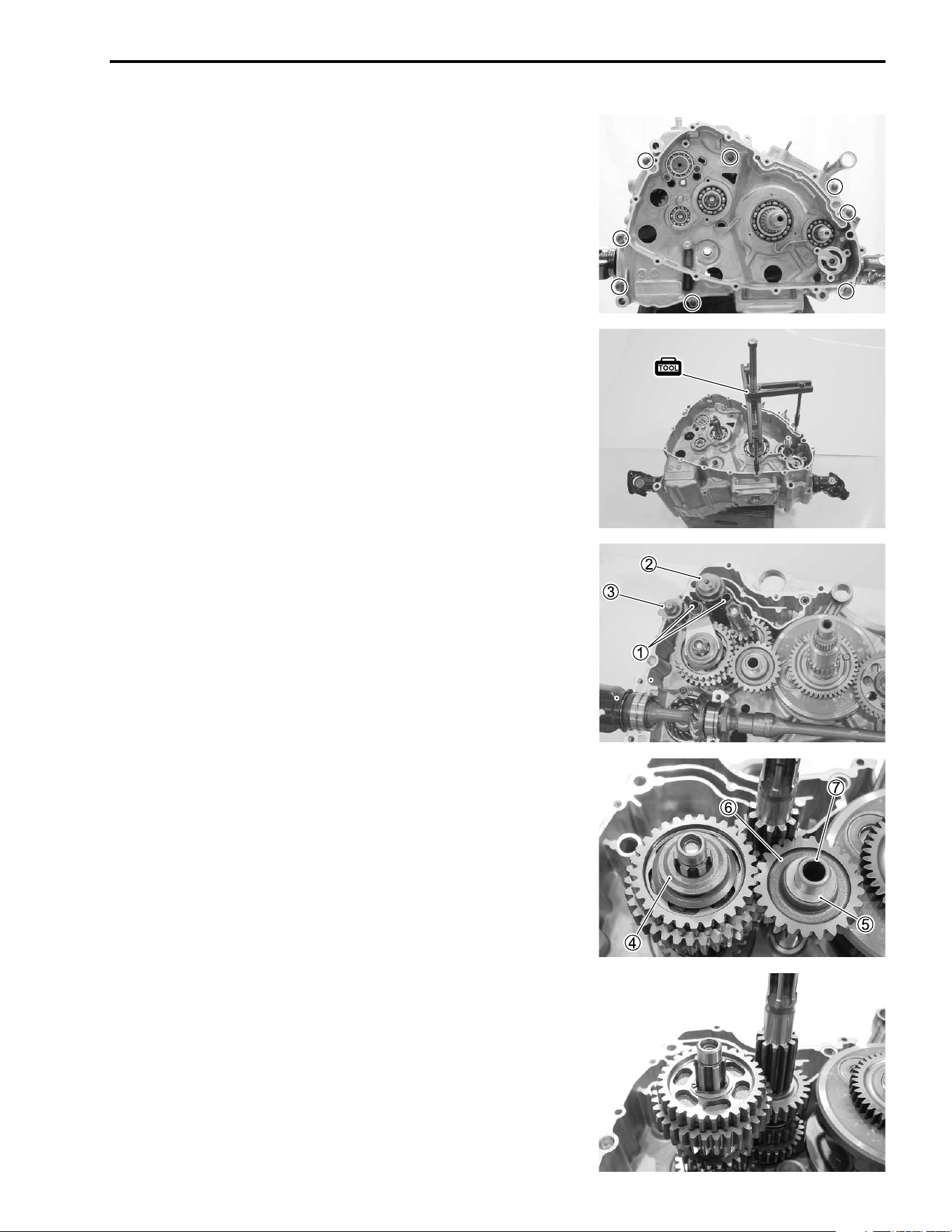
ENGINE 3-23
• Remove the right crankcase bolts.
• Separate the crankcase with the special tool.
NOTE:
* The crankcase separator plate is parallel with the end face of
the crankcase.
* The crankshaft must remain in the left crankcase half.
( 09920-13120: Crankcase separator
DRIVE TRAIN/GEARSHIFT CAM
• Remove the gearshift fork shafts
1.
• Remove the reverse gearshift fork, No. 1 and No. 2 gearshift
forks, and then pull out the gearshift cam
2.
• Remove the reverse shift cam
3.
• Remove the reverse dog
4 washer
5, the reverse idle gear
6 and shaft
7.
• Remove the driveshaft and countershaft assembly.
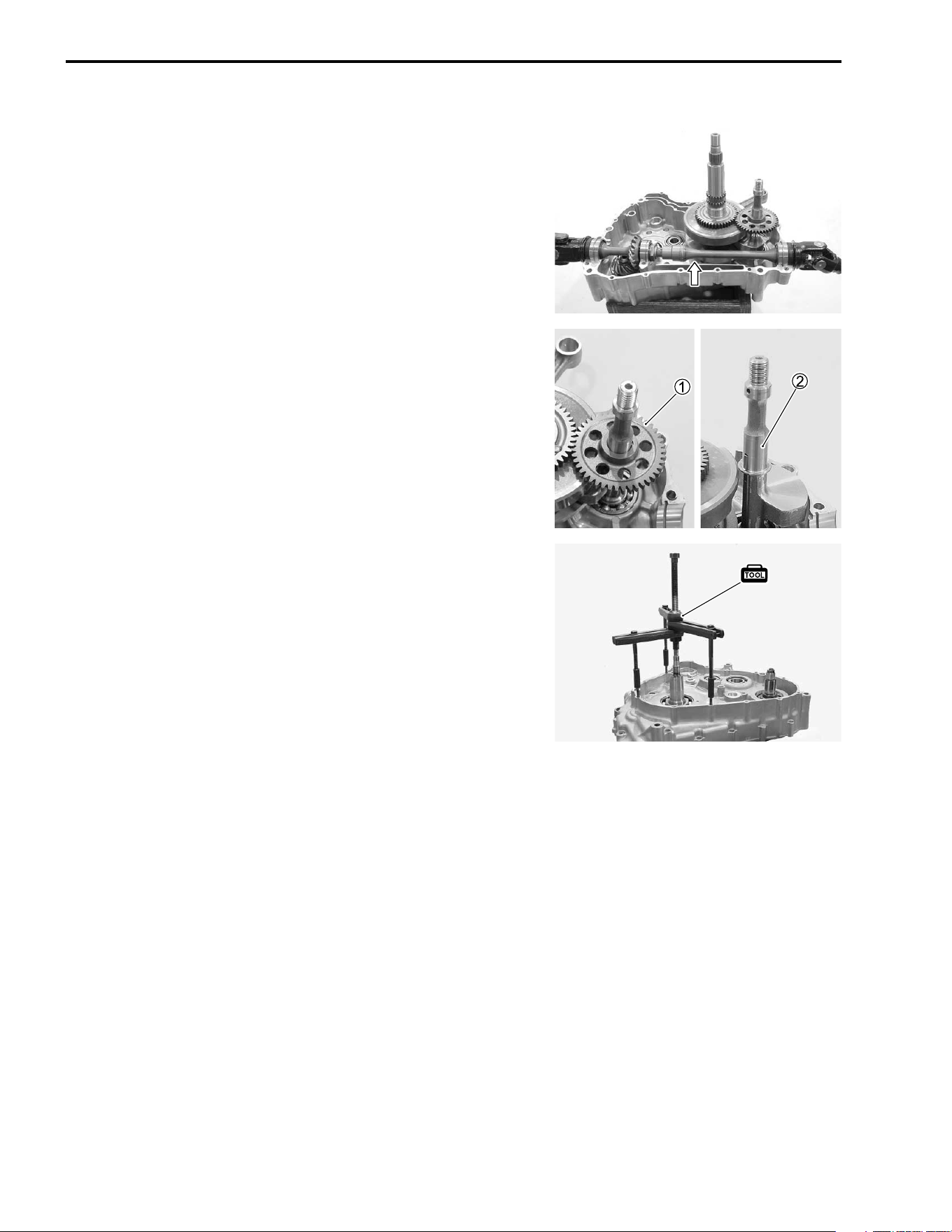
3-24 ENGINE
• Remove the output shaft assembly.
BALANCER
• Remove the balancershaft driven gear
1 and balancershaft
2.
CRANKSHAFT
• Remove the crankshaft with the special tool.
( 09920-13120: Crankcase separator
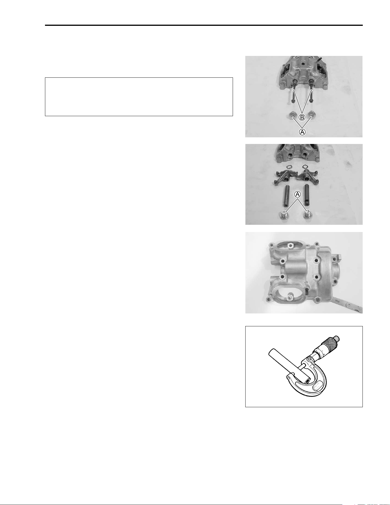
ENGINE 3-25
ENGINE COMPONENTS INSPECTION AND SERVICING
CYLINDER HEAD COVER
DISASSEMBLY
"
• Remove the rocker arm shaft bolts
A.
• Remove the rocker arm shafts by using 6 mm bolts
B.
CYLINDER HEAD COVER DISTORTION
After removing sealant from the fitting surface of the cylinder
head cover, place the cylinder head cover on a surface plate
and check for distortion with a thickness gauge.
% Cylinder head cover distortion
Service Limit: 0.05 mm (0.002 in)
( 09900-20803: Thickness gauge
If the distortion exceeds the limit, replace the cylinder head
cover.
ROCKER ARM SHAFT O.D.
Measure diameter of rocker arm shaft.
% Rocker arm O.D. (IN & EX)
Standard: 11.973 – 11.984 mm (0.4714 – 0.4718 in)
( 09900-20205: Micrometer (0 – 25 mm)
Be sure to identify each removed part as to its loca-
tion, and lay the parts out in groups designated as
“Exhaust”, “Intake”, so that each will be restored to
the original location during assembly.
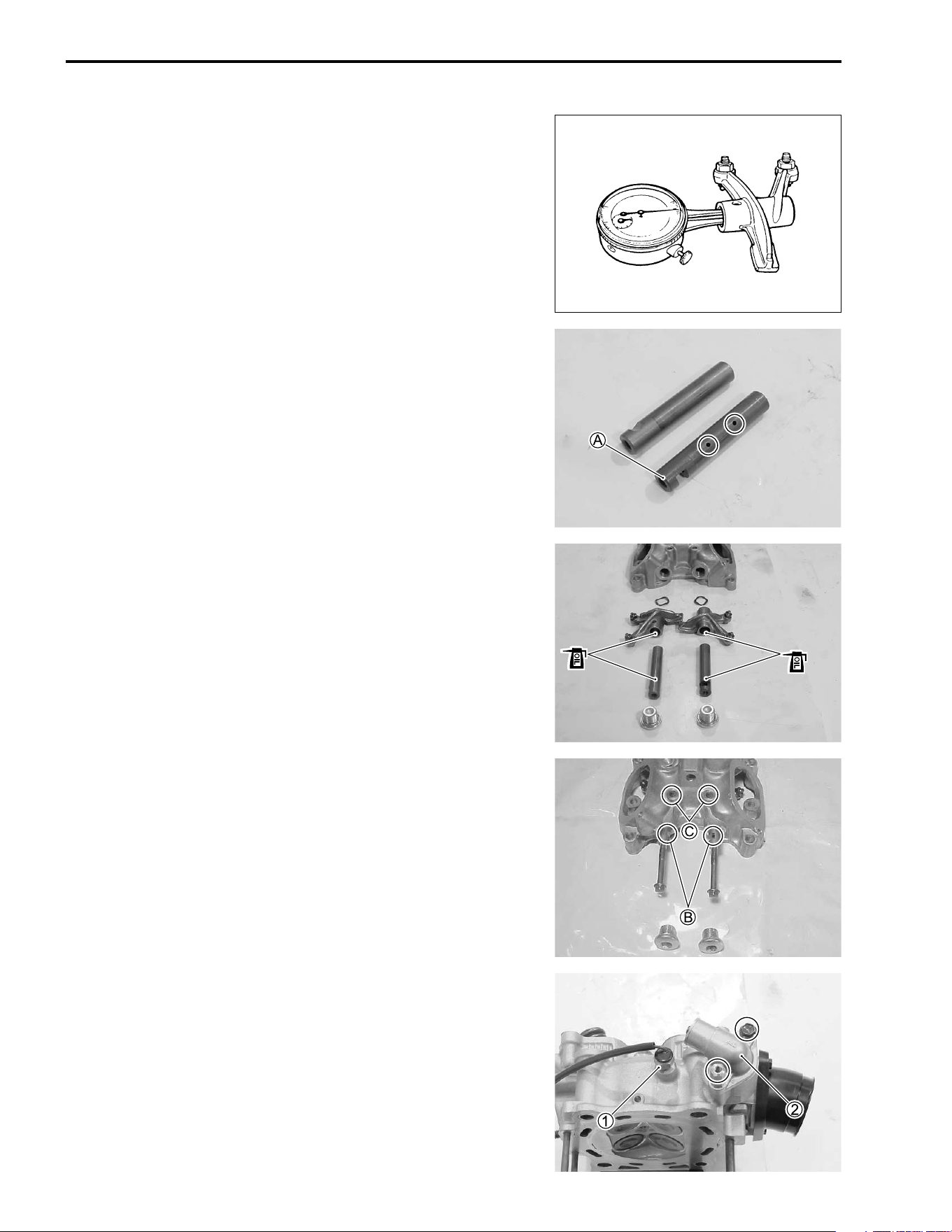
3-26 ENGINE
ROCKER ARM I.D.
When checking the valve rocker arm, the inside diameter of the
valve rocker arm and wear of the camshaft contacting surface
should be checked.
% Rocker arm I.D.
Standard: 12.000 – 12.018 mm (0.4724 – 0.4731 in)
( 09900-20605: Dial calipers
REASSEMBLY
NOTE:
Intake rocker arm shaft
A has the oil holes.
• Apply engine oil to the rocker arms and their shafts.
• Install the rocker arms and tighten the rocker arm shaft bolts
to the specified torque.
#
##
# Rocker arm shaft bolt: 28 N·m (2.8 kgf-m, 20.0 lb-ft)
NOTE:
Align the groove
B on the rocker arm shaft with the hole
C on
the cylinder head cover.
CYLINDER HEAD
DISASSEMBLY
• Remove the engine coolant temperature switch
1 and ther-
mostat cover
2.
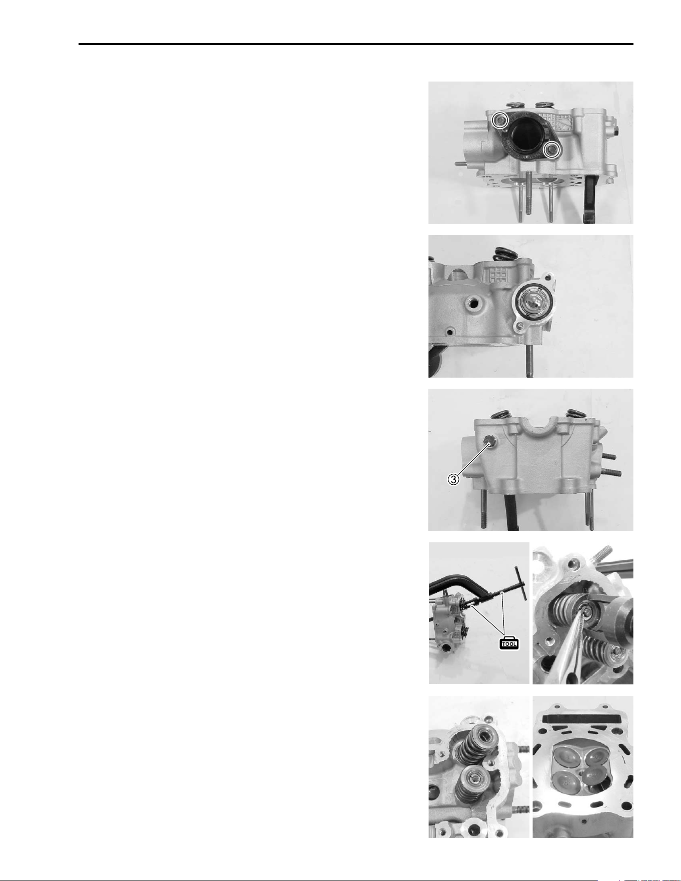
ENGINE 3-27
• Remove the intake pipe.
• Remove the thermostat.
• Remove the cam chain tensioner bolt
3.
• Compress the valve spring and remove the valve cotters from
the valve stem with the special tools.
( 09916-14510: Valve spring compressor
09916-14910: Attachment
09916-84511: Tweezers
• Remove the valve spring retainer and valve spring.
• Remove the valve from the other side.
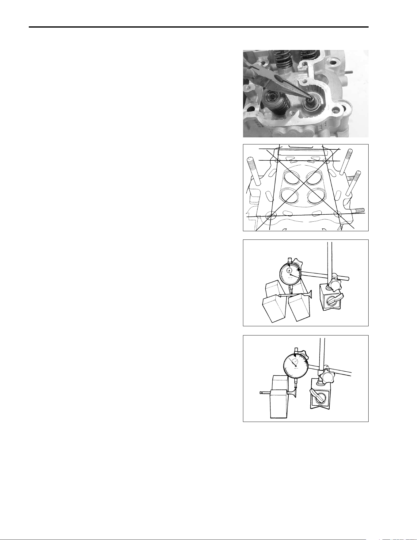
3-28 ENGINE
• Remove the oil seal with long-nose pliers.
• Remove the valve spring seat.
NOTE:
Removal of valves completes ordinary disassembling work. If
valve guides have to be removed for replacement after inspect-
ing the related parts, carry out the steps shown in the valve
guide servicing.
CYLINDER HEAD DISTORTION
• Decarbonize the combustion chamber.
Check the gasket surface of the cylinder head for distortion
using a straightedge and thickness gauge. Take clearance read-
ings at several places. If any clearance reading exceeds the ser-
vice limit, replace the cylinder head with a new one.
% Cylinder head distortion
Service Limit: 0.05 mm (0.002 in)
( 09900-20803: Thickness gauge
VALVE STEM RUNOUT
Support the valve with “V” blocks, as shown, and check its
runout with a dial gauge.
The valve must be replaced if the runout exceeds the limit.
% Valve stem runout
Service Limit: 0.05 mm (0.002 in)
( 09900-20701: Magnetic stand
09900-20607: Dial gauge (1/100 mm)
09900-21304: V-block
VALVE HEAD RADIAL RUNOUT
Place the dial gauge at right angles to the valve head face, and
measure the valve head radial runout.
If it exceeds limit, replace the valve.
% Valve head radial runout
Service Limit: 0.03 mm (0.001 in)
( 09900-20701: Magnetic stand
09900-20607: Dial gauge (1/100 mm)
09900-21304: V-block
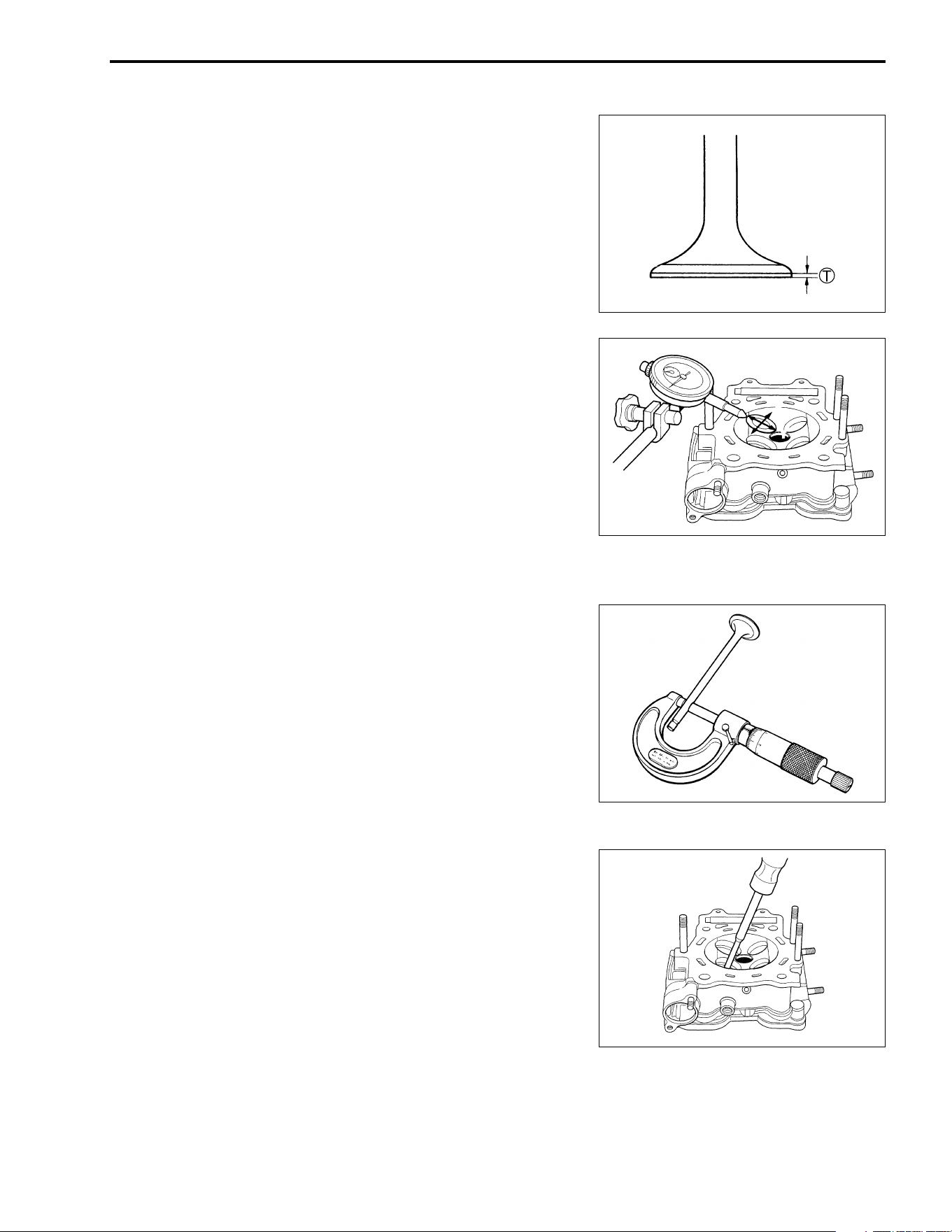
ENGINE 3-29
VALVE FACE WEAR
Visually inspect each valve face for wear or damage. If any
abnormal wear is found, replace the respective valve with a new
one. Measure the valve head thickness
T. If the valve head
thickness is not within the specified value, replace the value with
a new one.
% Valve head thickness
T
TT
T
Service Limit: 0.5 mm (0.02 in)
( 09900-20101: Vernier calipers
VALVE STEM DEFLECTION
Lift the valve about 10 mm (0.39 in) from the valve seat. Mea-
sure the valve stem deflection in two directions, “X” and “Y”, per-
pendicular to each other, by positioning the dial gauge as
shown. If the deflection measured exceeds the limit, (see below)
then determine whether the valve or the guide should be
replaced with a new one.
% Valve stem deflection (IN & EX)
Service Limit: 0.35 mm (0.014 in)
( 09900-20607: Dial gauge (1/100 mm)
09900-20701: Magnetic stand
VALVE STEM WEAR
If the valve stem is worn down to the limit, as measured with a
micrometer, where the clearance is found to be in excess of the
limit indicated replace the valve, if the stem is within the limit,
then replace the guide. After replacing valve or guide, be sure to
re-check the clearance.
% Valve stem O.D.
Standard (IN) : 4.975 – 4.990 mm (0.1959 – 0.1965 in)
(EX) : 4.955 – 4.970 mm (0.1951 – 0.1957 in)
( 09900-20205: Micrometer (0 – 25 mm)
VALVE GUIDE SERVICING
• Using the valve guide remover, drive the valve guide out
toward the intake or exhaust rocker arm side.
( 09916-44310: Valve guide remover/installer
NOTE:
* Discard the removed valve guide subassemblies.
* Only oversized valve guides are available as replacement
parts. (Part No. 11115-14D71)
X
Y
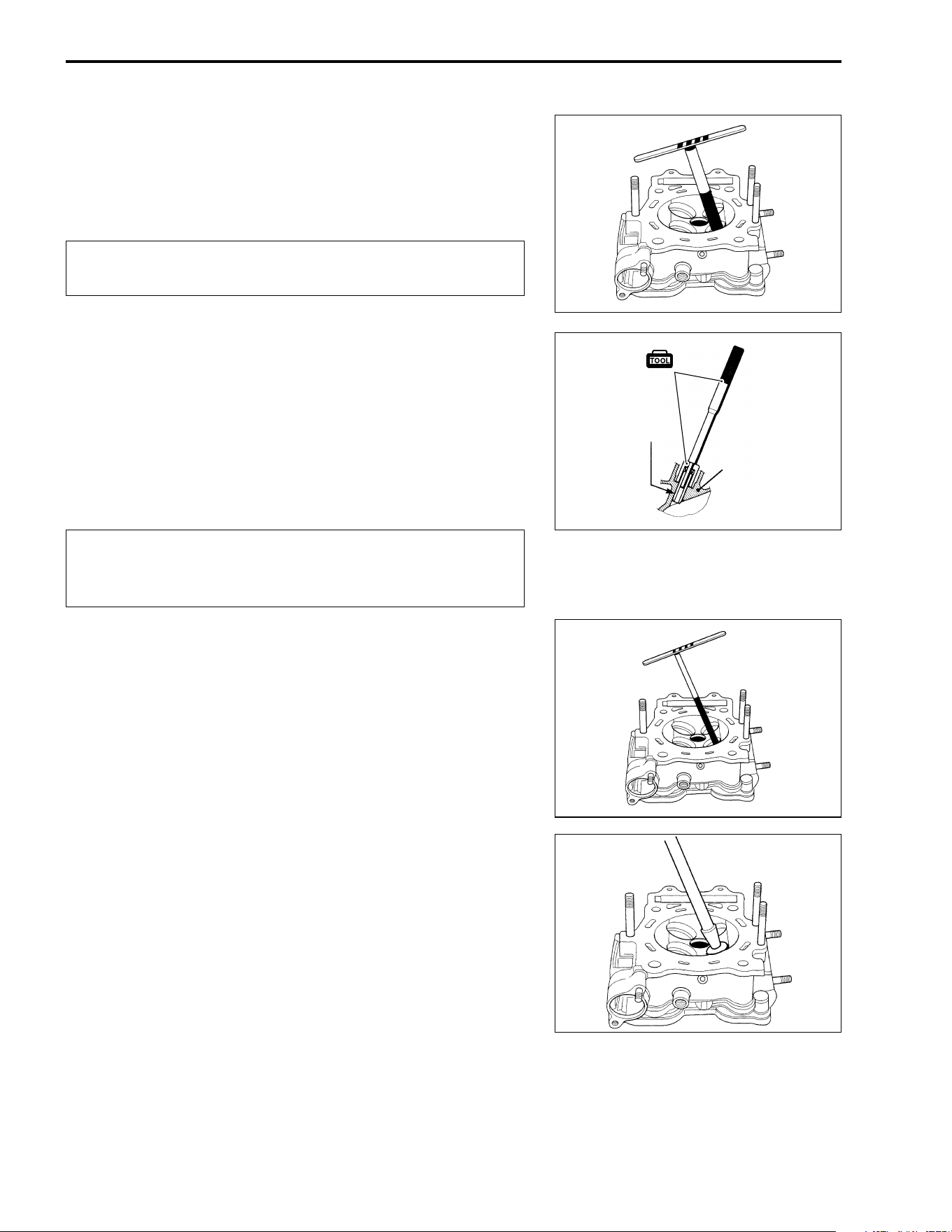
3-30 ENGINE
• Re-finish the valve guide holes in the cylinder head with the
reamer and handle.
( 09916-34580: Valve guide reamer (10.8 mm)
09916-34542: Reamer handle
"
• Oil the stem hole of each valve guide and drive the guide into
the guide hole with the special tools.
NOTE:
Install the valve guide until the attachment contacts with the cyl-
inder head.
( 09916-57330: Valve guide installer
09916-57340: Valve guide installer attachment
"
• After fitting all valve guides, re-finish their guiding bores with
the reamer. Be sure to clean and oil the guide after reaming.
( 09916-34570: Valve guide reamer (5.0 mm)
09916-34542: Reamer handle
NOTE:
Insert the reamer from the combustion chamber and always turn
the reamer handle clockwise.
VALVE SEAT WIDTH
• Coat the valve seat with prussian blue uniformly. Fit the valve
and tap the coated seat with the valve face in a rotating man-
ner, in order to obtain a clear impression of the seating con-
tact. In this operation, use the valve lapper to hold the valve
head.
• The ring-like dye impression left on the valve face must be
continuous – without any break. In addition, the width of the
dye ring, which is the visualized seat “width”, must be within
the following specification:
When refinishing or removing the reamer from the
valve guide hole, always turn it clockwise.
Failure to oil the valve guide hole before driving the
new guide into place may result in a damaged guide or
head.
Valve guide
Cylinder head
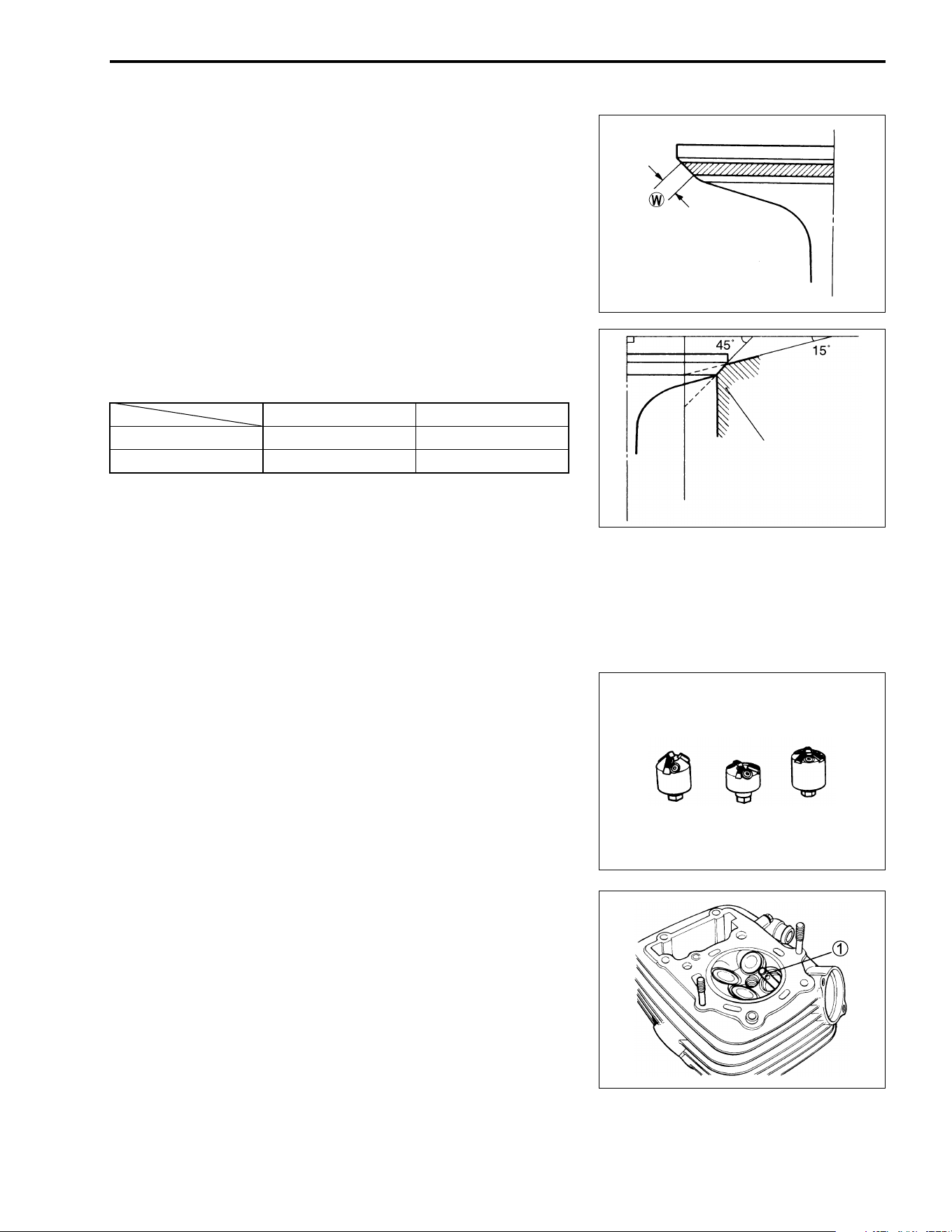
ENGINE 3-31
% Valve seat width
W
Standard: 0.9 – 1.1 mm (0.035 – 0.043 in)
( 09916-10911: Valve lapper set
If either requirement is not met, correct the seat by servicing it
as follows:
VALVE SEAT SERVICING
The valve seats for intake and exhaust valves are machined to
two different angles. The seat contact surface is cut at 45°.
NOTE:
The valve seat contact area must be inspected after each cut.
( 09916-21111: Valve seat cutter set
09916-24900: Valve seat cutter set
09916-22410: Solid pilot (N-140-5.0)
09916-24311: Solid pilot (N-100-5.0)
09916-24935: Valve seat cutter (N-608)
• Insert the solid pilot
1 (09916-24311: N-100-5.0) with a slight
rotation. Seat the pilot snugly.
INTAKE EXHAUST
15° N-212 N-121
45° N-608 N-608
Valve seat
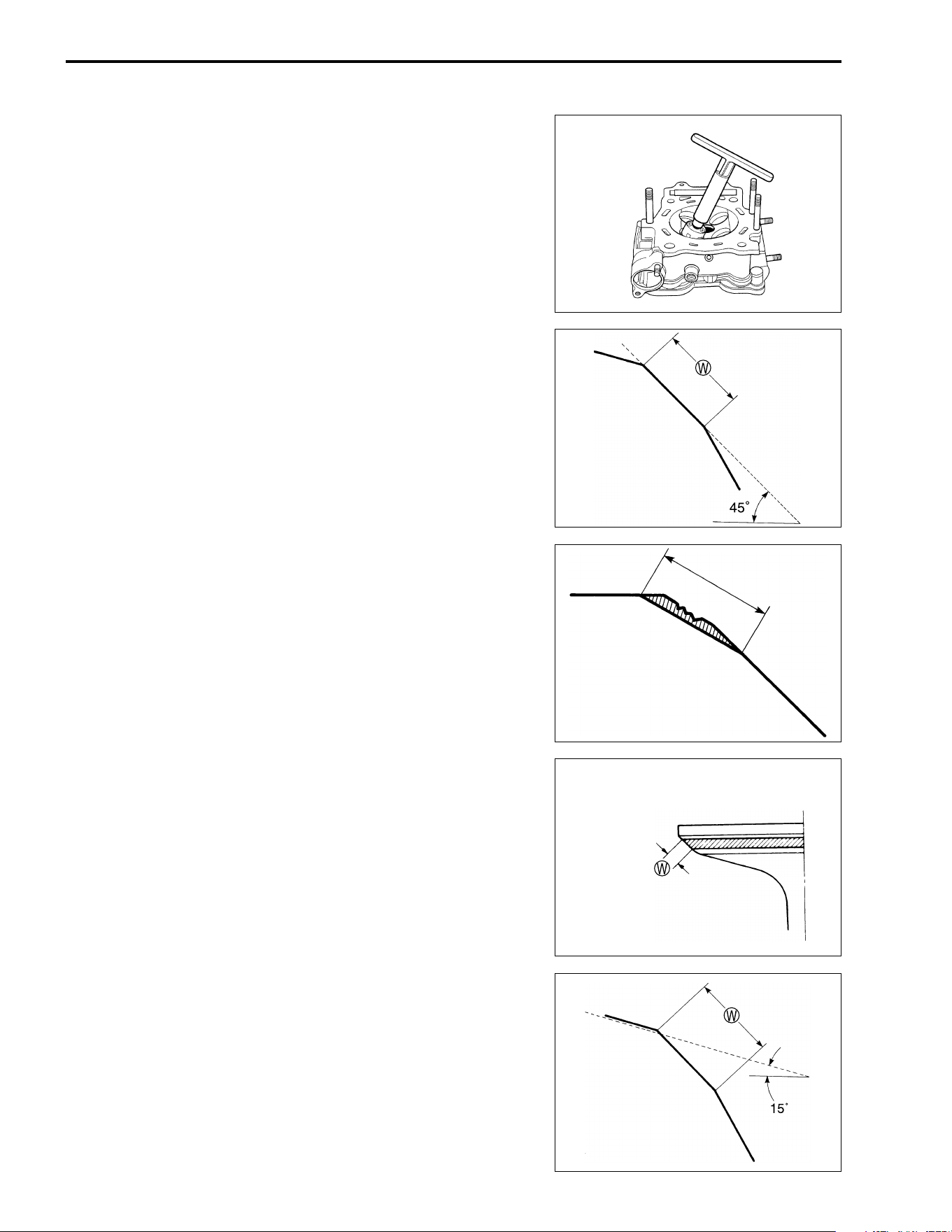
3-32 ENGINE
• Install the 45° cutter, attachment and T-handle.
INITIAL SEAT CUT
• Using the 45° cutter, descale and clean up the seat. Rotate
the cutter one or two turns.
• Measure the valve seat width
W after every cut.
• If the valve seat is pitted or burned, use the 45° cutter to con-
dition the seat some more.
NOTE:
Cut only the minimum amount necessary from the seat to pre-
vent the possibility of the valve stem becoming too close to the
camshaft.
TOP NARROWING CUT
• If the contact area
W is too high on the valve, or if it is too
wide, use the 15° cutter to lower and narrow the contact area.
The contact area too high and too
wide on face of valve
ENGINE 3-33
FINAL SEAT CUT
• If the contact area
W is too low or too narrow, use the 45° cut-
ter to raise and widen the contact area.
NOTE:
After cutting the 15° angle, it is possible that the valve seat (45°)
is too narrow. If so, re-cut the valve seat to the correct width.
• After the desired seat position and width is achieved, use the
45° cutter very lightly to clean up any burrs caused by the pre-
vious cutting operations.
"
NOTE:
After servicing the valve seats, be sure to check the valve clear-
ance after the cylinder head has been reinstalled. (!2-5)
• Clean and assemble the head and valve components. Fill the
intake and exhaust ports with gasoline to check for leaks.
• If any leaks occur, inspect the valve seat and face for burrs or
other things that could prevent the valve from sealing.
)
The contact area too low and too
narrow on face of valve
Do not use lapping compound after the final cut is
made. The finished valve seat should have a velvety
smooth finish but not a highly polished or shiny fin-
ish. This will provide a soft surface for the final seat-
ing of the valve which will occur during the first few
seconds of engine operation.
Always use extreme caution when handling gasoline.
3-34 ENGINE
VALVE STEM END CONDITION
Inspect the valve stem end face for pitting and wear. If pitting or
wear of the stem end face are present, the valve stem end may
be resurfaced, providing that the length
1 will not be reduced to
less than the service limit. If this length becomes less than the
service limit, the valve must be replaced.
% Valve stem end length
Service Limit: 1.7 mm (0.07 in)
VALVE SPRING
The force of the coil spring keeps the valve seat tight. Weakened
spring result in reduced engine power output, and often account
for the chattering noise coming from the valve mechanism.
Check the valve springs for proper strength by measuring their
free length and also by the force required to compress them. If the
spring length is less than the service limit, or if the force required
to compress the spring does not fall within the range specified,
replace both the inner and outer springs as a set.
( 09900-20101: Vernier calipers
% Valve spring free length (IN & EX)
Service Limit : 38.8 mm (1.53 in)
% Valve spring tension (IN & EX)
Standard: 18.2 – 21.0 kgf
(40.1 – 46.3 lbs)
at length 31.5 mm (1.24 in)
REASSEMBLY
• Install each valve spring seat.
• Apply molybdenum oil solution to each oil seal and press-fit
them into position.
( 09916-44310: Valve guide remover/installer
* MOLYBDENUM OIL SOLUTION
"
Do not reuse the oil seal.
18.2 – 21.0 kgf (40.1 – 46.3 lbs)
31.5 mm (1.24 in)
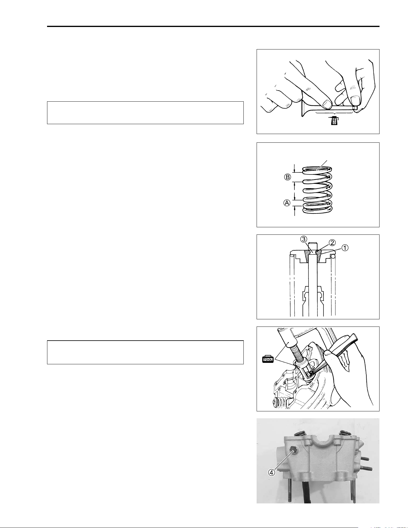
ENGINE 3-35
• Insert the valves, with their stems coated with molybdenum oil
solution all around and along the full stem length without any
break.
* MOLYBDENUM OIL SOLUTION
"
• Install the valve spring with the small-pitch portion
A facing
cylinder head.
B Large-pitch portion.
Put on the valve spring retainer using the valve spring compres-
sor, press down the spring, fit the two cotter halves to the stem
end, and release the compressor to allow the cotter
1 to wedge
in between seat and stem. Be sure that the rounded lip
2 of the
cotter fits snugly into the groove
3 in the stem end.
( 09916-14510: Valve spring compressor
09916-14910: Valve spring compressor attachment
09916-84511: Tweezers
"
• Tighten the cam chain tensioner bolt
4 to the specified
torque.
# Cam chain tensioner bolt: 13 N·m (1.3 kgf-m, 9.5 lb-ft)
When inserting each valve, take care not to damage
the lip of the stem seal.
Light blue paint
Be sure to restore each spring, valve and spring
retainer to their original positions.
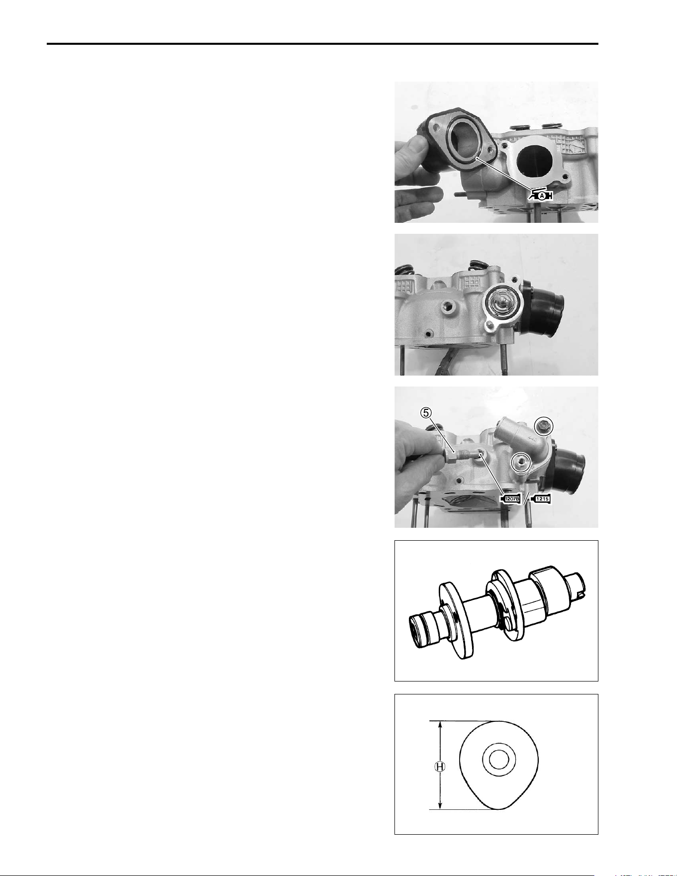
3-36 ENGINE
• Apply SUZUKI SUPER GREASE “A” to the O-ring and install
the intake pipe.
' 99000-25030: SUZUKI SUPER GREASE “A” (USA)
99000-25010: SUZUKI SUPER GREASE “A” (Others)
• Install the thermostat. (!6-12)
• Install the thermostat cover.
• Apply SUZUKI BOND “1207B”/“1215” to the engine coolant
temperature switch
5 and tighten it to the specified torque.
+ 99104-31140: SUZUKI BOND “1207B” (USA)
, 99000-31110: SUZUKI BOND “1215” (Others)
# Engine coolant temperature switch:
30 N·m (3.0 kgf-m, 21.5 lb-ft)
CAMSHAFT
The camshaft should be checked for wear and also for runout of
cams and journals if the engine has been noted to produce
abnormal noise or vibration or to lack output power. Any of these
malconditions could be caused by a worn camshaft.
CAMSHAFT CAM WEAR
Worn-down cams are often the cause of mistimed valve opera-
tion resulting in reduced output power. The limit of cam wear is
specified for both intake and exhaust cam in terms of cam height
H, which is to be measured with a micrometer. Replace cam-
shaft if found worn down to the limit.
% Cam height
H
HH
H
Service Limit (IN) : 33.130 mm (1.3043 in)
(EX) : 33.200 mm (1.3071 in)
( 09900-20202: Micrometer (25 – 50 mm)
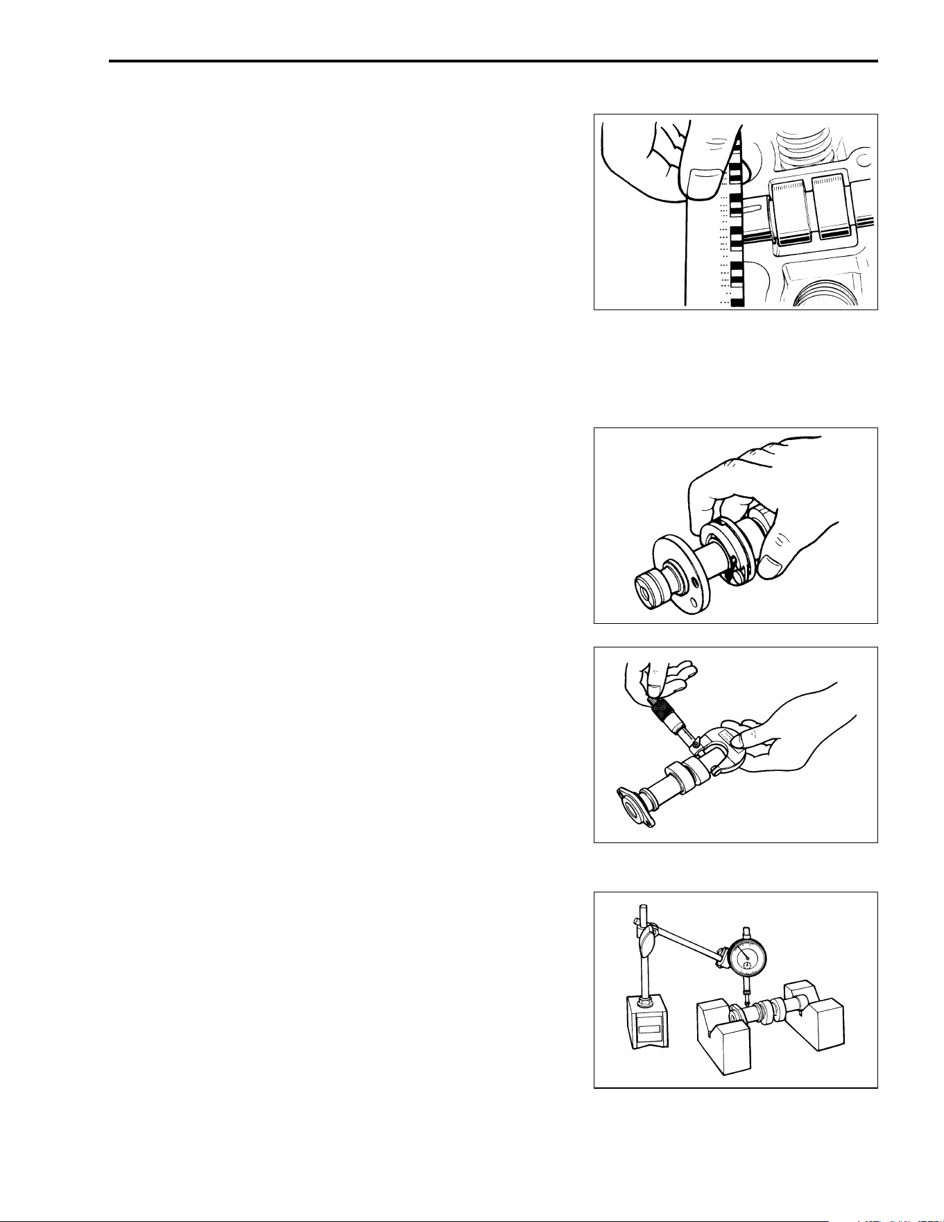
ENGINE 3-37
CAMSHAFT JOURNAL WEAR
Determine whether each journal is worn down to the limit or not
by measuring camshaft journal oil clearance with the camshaft
installed. Use plastigauge to read the clearance, which is speci-
fied as follows:
% Camshaft journal oil clearance
Service Limit: 0.150 mm (0.0059 in)
( 09900-22302: Plastigauge
NOTE:
To properly measure the oil clearance with plastigauge, all gas-
ket material must be removed from fitting surfaces of cylinder
head and cover. Do not apply SUZUKI BOND “1216B” until after
the oil clearance has been determined.
• Tighten the cylinder head cover bolts evenly and diagonally to
the specified torque.
# Cylinder head cover bolt
(M6): 10 N·m (1.0 kgf-m, 7.0 lb-ft)
NOTE:
Do not rotate the camshafts with the plastigauge in place.
Remove the cylinder head cover, and read the width of the com-
pressed plastigauge with envelop scale. This measurement
should be taken at the widest part.
If the camshaft journal oil clearance measured exceeds the limit,
measure the outside diameter of camshaft.
Replace either the cylinder head set or the camshaft if the clear-
ance is incorrect.
% Camshaft journal O.D.
Standard (Sprocket side): 21.959 – 21.980 mm
(0.8645 – 0.8654 in)
(Other side) : 17.466 – 17.484 mm
(0.6876 – 0.6883 in)
( 09900-20205: Micrometer (0 – 25 mm)
CAMSHAFT RUNOUT
Measure the runout with a dial gauge. Replace the camshaft if
the runout exceeds the limit.
% Camshaft runout (IN & EX)
Service Limit: 0.10 mm (0.004 in)
( 09900-20607: Dial gauge (1/100, 10 mm)
09900-20701: Magnetic stand
09900-21304: V-block (100 mm)
3-38 ENGINE
CAM CHAIN TENSION ADJUSTER
CAM CHAIN TENSION ADJUSTER
Insert the
- screwdriver into the slotted end of cam chain ten-
sion adjuster and turn it clockwise to lessen the tension and
release the
- screwdriver. Then check the push rod movement.
If the push rod is stuck or spring mechanism failed, replace the
cam chain tension adjuster with a new one.
CAM CHAIN TENSIONER/GUIDE
Check the contacting surface of the cam chain guide for wear
and damage. If it is found to be damaged, replace it with a new
one.
CYLINDER
CYLINDER DISTORTION
Check the gasketed surface of the cylinder for distortion with a
straightedge and thickness gauge, taking a clearance reading at
several places as indicated. If the largest reading at any position
of the straightedge exceeds the limit, replace the cylinder.
% Cylinder distortion
Service Limit: 0.05 mm (0.002 in)
( 09900-20803: Thickness gauge
CYLINDER BORE
Inspect the cylinder wall for any scratches, nicks or other dam-
age. Measure the cylinder bore diameter at six places.
% Cylinder bore
Service Limit: 87.500 – 87.515 (3.4449 – 3.4455 in)
( 09900-20508: Cylinder gauge set
09900-20511: Cylinder gauge rod (88 mm)
ENGINE 3-39
-
PISTON
PISTON DIAMETER
Using a micrometer, measure the piston outside diameter at the
place shown in Fig. If the measurement is less than the limit,
replace the piston.
% Piston diameter
Service Limit: 87.380 mm (3.4402 in)
( 09900-20204: Micrometer (75 – 100 mm)
PISTON RING TO GROOVE CLEARANCE
Using a thickness gauge, measure the side clearances of the
1st and 2nd rings. If any of the clearances exceeds the limit,
replace both piston and piston rings.
% Piston ring to groove clearance
Service Limit (1st) : 0.18 mm (0.0071 in)
(2nd): 0.15 mm (0.0059 in)
% Piston ring groove width
Standard (1st) : 1.01 – 1.03 mm (0.0398 – 0.0406 in)
(2nd): 1.21 – 1.23 mm (0.0398 – 0.0484 in)
(Oil) : 2.51 – 2.53 mm (0.0988 – 0.0996 in)
% Piston ring thickness
Standard (1st) : 0.970 – 0.990 mm
(0.0382 – 0.0390 in)
(2nd): 1.170 – 1.190 mm
(0.0461 – 0.0469 in)
( 09900-20803: Thickness gauge
09900-20205: Micrometer (0 – 25 mm)
15 mm (0.6 in)
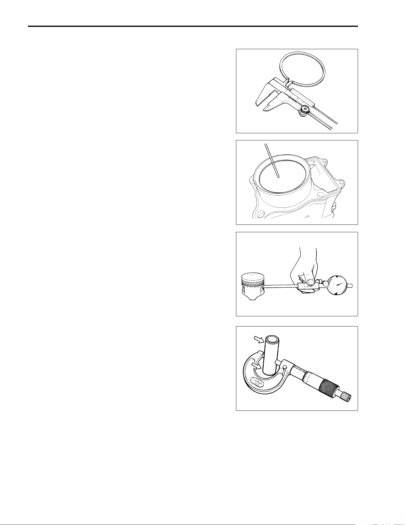
3-40 ENGINE
-
PISTON RING FREE END GAP AND END GAP
Before installing piston rings, measure the free end gap of each
ring using vernier calipers. Next, fit the ring in the cylinder, and
measure each ring end gap using a thickness gauge.
If any ring has an excess end gap, replace the ring.
% Piston ring free end gap
Service Limit (1st) : 9.0 mm (0.35 in)
(2nd): 9.5 mm (0.37 in)
% Piston ring end gap
Service Limit (1st) : 0.50 mm (0.020 in)
(2nd): 0.50 mm (0.020 in)
( 09900-20101: Vernier calipers
09900-20803: Thickness gauge
PISTON PIN AND PIN BORE
Using a small bore gauge, measure the piston pin bore inside
diameter, and using a micrometer, measure the piston pin out-
side diameter. If the reading exceeds following limit, replace
both piston and piston pin.
% Piston pin bore I.D.
Service Limit: 23.030 mm (0.9067 in)
( 09900-20602: Dial gauge (1/1000 mm, 1 mm)
09900-22403: Small bore gauge (18 – 35 mm)
Using a micrometer, measure the piston pin outside diameter at
three positions.
% Piston pin O.D.
Service Limit: 22.980 mm (0.9047 in)
( 09900-20205: Micrometer (0 – 25 mm)
ENGINE 3-41
CONROD/CRANKSHAFT
CONROD SMALL END I.D.
Using a caliper gauge, measure the conrod small end inside
diameter.
% Conrod small end I.D.
Service Limit: 23.040 mm (0.9071 in)
( 09900-20605: Dial calipers (10 – 34 mm)
09900-22403: Small bore gauge (18 – 35 mm)
If the conrod small end inside diameter exceeds the above men-
tioned limit, replace the conrod.
CONROD DEFLECTION
Wear on the big end of the conrod can be estimated by checking
the movement of the small end of the rod. This method can also
check the extent of wear on the conrod’s big end.
% Conrod deflection
Service Limit: 3.0 mm (0.12 in)
( 09900-20701: Magnetic stand
09900-20607: Dial gauge (1/100 mm)
09900-21304: V-block
CONROD BIG END SIDE CLEARANCE
Push the big end of the conrod to one side and measure the
side clearance with a thickness gauge.
% Conrod big end side clearance
Service Limit: 1.0 mm (0.039 in)
( 09900-20803: Thickness gauge
If the clearance exceeds the limit, replace the crankshaft assem-
bly with a new one or bring the deflection and the side clearance
within the service limit by replacing the worn parts (conrod, big
end bearing, crank pin, etc.) with new ones.
CRANKSHAFT RUNOUT
Support the crankshaft with “V” blocks as shown, with the two
end journals resting on the blocks.
Position the dial gauge, as shown, and rotate the crankshaft
slowly to read the runout.
Correct or replace the crankshaft if the runout is greater than the
limit.
% Crankshaft runout
Service Limit: 0.050 mm (0.0019 in) at
A
0.080 mm (0.0031 in) at
B
( 09900-20607: Dial gauge (1/100 mm)
09900-20701: Magnetic stand
09910-21304: V-block set (100 mm)
3-42 ENGINE
CLUTCH
CLUTCH DRIVE PLATES
NOTE:
Wipe off engine oil from the clutch drive plates with a clean rag.
• Measure the thickness of drive plates with a vernier calipers.
• If each drive plate is not within the standard range, replace it
with a new one.
% Drive plate thickness
Service Limit: 2.62 mm (0.103 in)
( 09900-20101: Vernier calipers
• Measure the claw width of drive plates with a vernier calipers.
• Replace the drive plates found to have worn down to the limit.
% Drive plate claw width
Service Limit: 12.9 mm (0.51 in)
( 09900-20101: Vernier calipers
CLUTCH DRIVEN PLATES
NOTE:
Wipe off engine oil from the clutch driven plates with a clean rag.
• Measure each driven plate for distortion with a thickness
gauge and surface plate.
• Replace driven plates which exceed the limit.
% Driven plate distortion
Service Limit: 0.10 mm (0.004 in)
( 09900-20803: Thickness gauge
09900-21203: Surface plate
CLUTCH SPRING
• Measure the free length of each coil spring with a vernier cali-
pers, and compare the length with the specified limit.
• Replace all the springs if any spring is not within the limit.
% Clutch spring free length
Service Limit: 33.8 mm (1.33 in)
( 09900-20101: Vernier calipers
ENGINE 3-43
CLUTCH SHOES
Inspect the clutch shoes for chips, cracks, uneven wear, and
heat discoloration. Also, check the depth of the grooves on the
clutch shoes. If there is no groove at any part of the shoes,
replace the shoes as a set.
NOTE:
The clutch shoes must always be changed as a set.
CLUTCH WHEEL
Inspect the condition of the inner clutch wheel surface for scuffs,
scratches, cracks or uneven wear. If any damages are found,
replace the clutch wheel with a new one.
ONE-WAY CLUTCH
Put the one-way clutch onto the clutch wheel and install the
clutch shoe assembly. Rotate the clutch shoe assembly by hand
to inspect that the shoe assembly turns to one direction only and
never turns to the opposite direction. If the shoe assembly turns
to both directions or is locked, replace the one-way clutch with a
new one.
STARTER CLUTCH
• Remove the starter clutch securing bolts by holding the rotor
with the special tool.
( 09930-44541: Rotor holder
• Install the starter clutch in the proper direction.
NOTE:
* When installing the starter clutch onto the rotor, make sure the
flange side
A of the one way clutch faces to the rotor.
* The arrow mark
B must face to the engine side.
• Apply engine oil to the starter clutch.
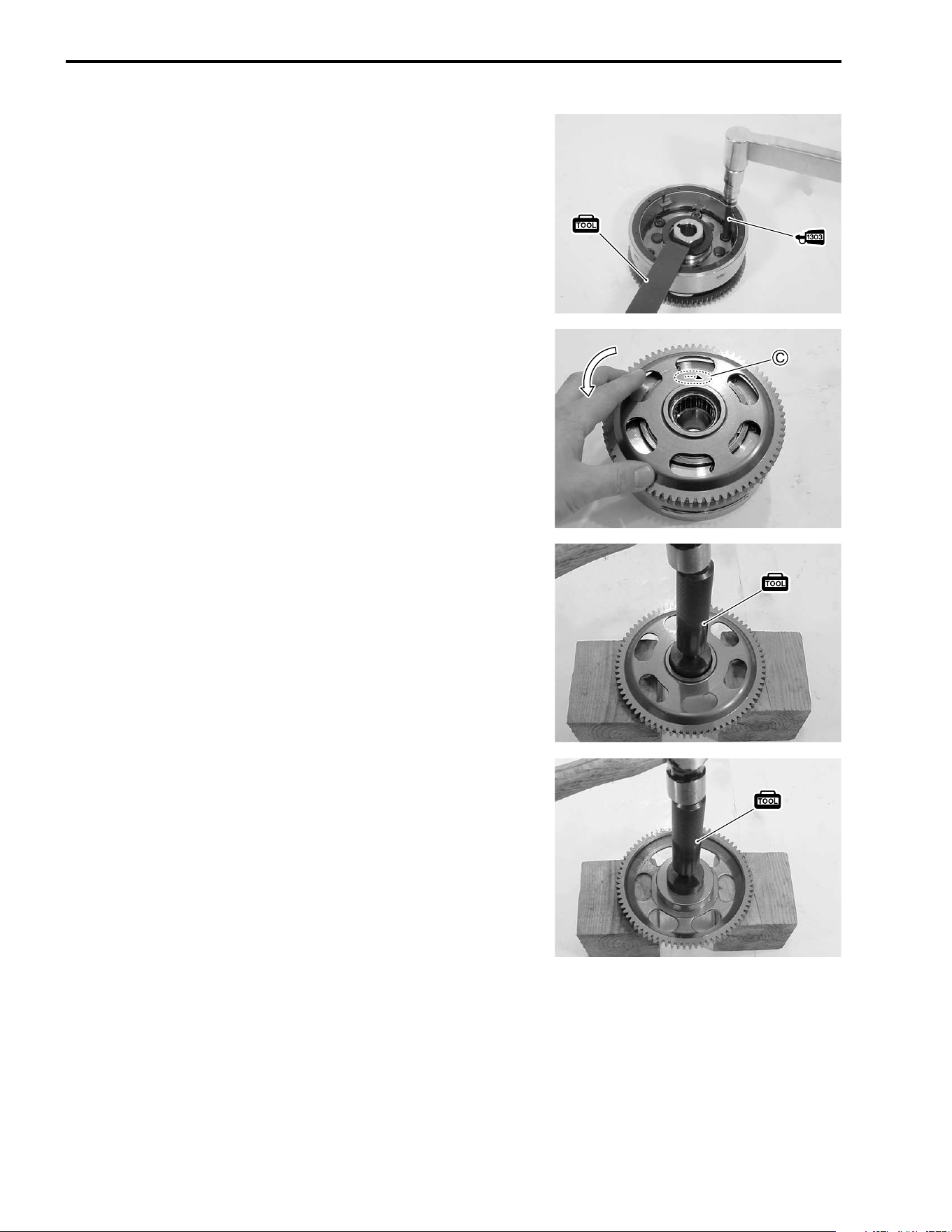
3-44 ENGINE
• Apply THREAD LOCK SUPER “1303” to the bolts, and then
tighten them to the specified torque with a offset wrench.
# Starter clutch bolt: 26 N·m (2.6 kgf-m, 19.0 lb-ft)
$ 99000-32030: THREAD LOCK SUPER “1303”
( 09930-44541: Rotor holder
• Install the starter driven gear to the starter clutch.
• Check that the starter driven gear turns in the opposite direc-
tion of the arrow mark
c on the rotor while holding the gener-
ator rotor. The gear never turns in the direction of the arrow.
• If there is anything unusual, replace the one way clutch.
--
• Check the starter driven gear bearing. If there is anything
unusual, replace the bearing.
• Remove the bearing with the special tool.
( 09913-70210: Bearing installer/remover set
• Install the bearing with the special tool.
( 09913-70210: Bearing installer/remover set
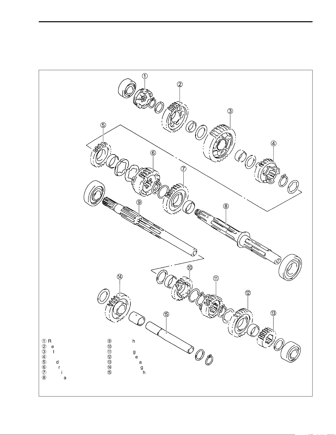
ENGINE 3-45
TRANSMISSION
DISASSEMBLY
• Disassemble the transmission as shown.
1
Reverse gear dog
2
Reverse driven gear
3
1st driven gear
4
4th driven gear
5
3rd driven gear
6
5th driven gear
7
2nd driven gear
8
Driveshaft
9
Countershaft
0
4th drive gear
A
3rd drive gear
B
5th drive gear
C
2nd drive gear
D
Reverse idle gear
E
Reverse idle shaft
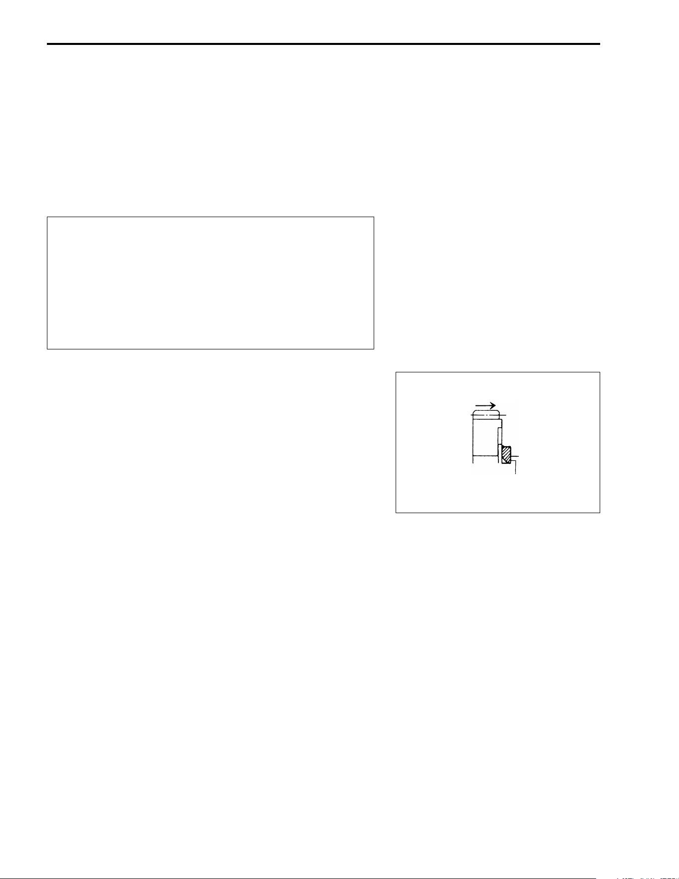
3-46 ENGINE
REASSEMBLY
Assemble the transfer in the reverse order of disassembly. Pay
attention to the following points:
NOTE:
* Always use new snap rings.
* Before installing the gears, coat lightly engine oil to the shafts
and gears.
"
• When installing a new snap ring, pay attention to the direction
of the snap ring. Fit it to the side where the thrust is as shown
in the figure.
* Never reuse a snap ring. After a snap ring has been
removed from a shaft, it should be discarded and a
new snap ring must be installed.
* When installing a new snap ring, care must be taken
not to expand the end gap larger than required to slip
the snap ring over the shaft.
* After installing a snap ring, always ensure that it is
completely seated in its groove and securely fitted.
Thrust
Sharp edge
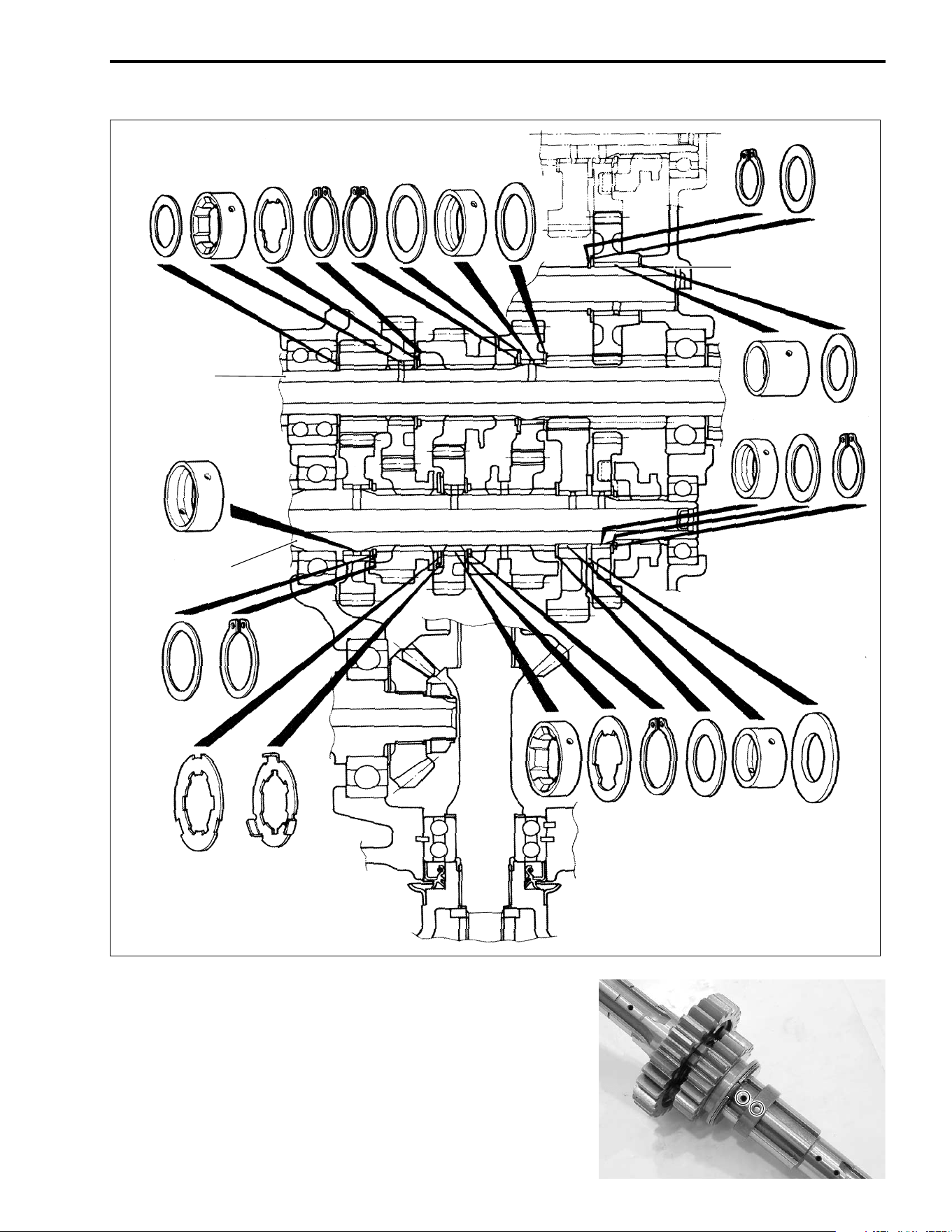
ENGINE 3-47
• When installing the bushings, align the shaft hole with the
bushing hole.
Reverse idle shaft
Countershaft
Driveshaft
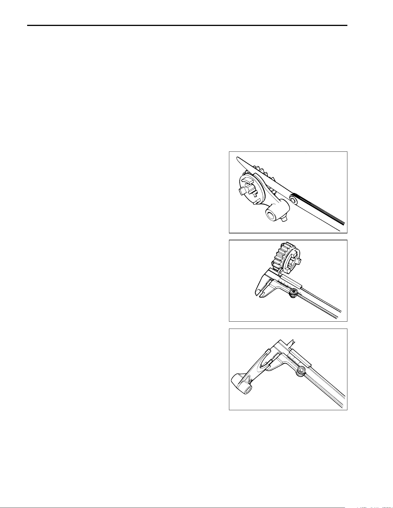
3-48 ENGINE
GEARSHIFT FORK
SHIFT FORK TO GROOVE CLEARANCE
Using a thickness gauge, check the shifting fork clearance in the
groove of its gear.
The clearance for each of the three shifting forks plays an impor-
tant role in the smoothness and positiveness of shifting action.
If the clearance exceeds the limit, replace the fork or its gear, or
both.
% Shift fork to groove clearance
Standard: 0.10 – 0.30 mm (0.004 – 0.012 in)
Service Limit: 0.50 mm (0.020 in)
( 09900-20803: Thickness gauge
09900-20101: Vernier calipers
% Shift fork groove width
Standard (No. 1/No. 2): 5.50 – 5.60 mm
(0.217 – 0.220 in)
(Reverse): 5.00 – 5.10 mm
(0.197 – 0.201 in)
% Shift fork thickness
Standard (No. 1/No. 2): 5.30 – 5.40 mm
(0.209 – 0.213 in)
(Reverse): 4.80 – 4.90 mm
(0.189 – 0.193 in)
ENGINE 3-49
TRANSFER GEARSHIFT CAM
OIL SEAL INSPECTION
Inspect the lip of the oil seal for wear or damage. If any damages
are found, replace the oil seal with a new one.
OIL SEAL REMOVAL
• Remove the oil seal with a suitable bar.
NOTE:
If there is no abnormal condition, the oil seal removal is not nec-
essary.
"
OIL SEAL INSTALLATION
• Press the oil seal into the gearshift shaft with special tool to
the depth of 0 – 1 mm (0 – 0.04 in).
( 09924-84521: Bearing installer set
NOTE:
The stamped mark on the oil seal faces outside.
• Apply a small quantity of the SUZUKI SUPER GREASE “A” to
the oil seal lip.
' 99000-25030: SUZUKI SUPER GREASE “A” (USA)
99000-25010: SUZUKI SUPER GREASE “A” (Others)
The removed oil seal must be replaced with a new one.
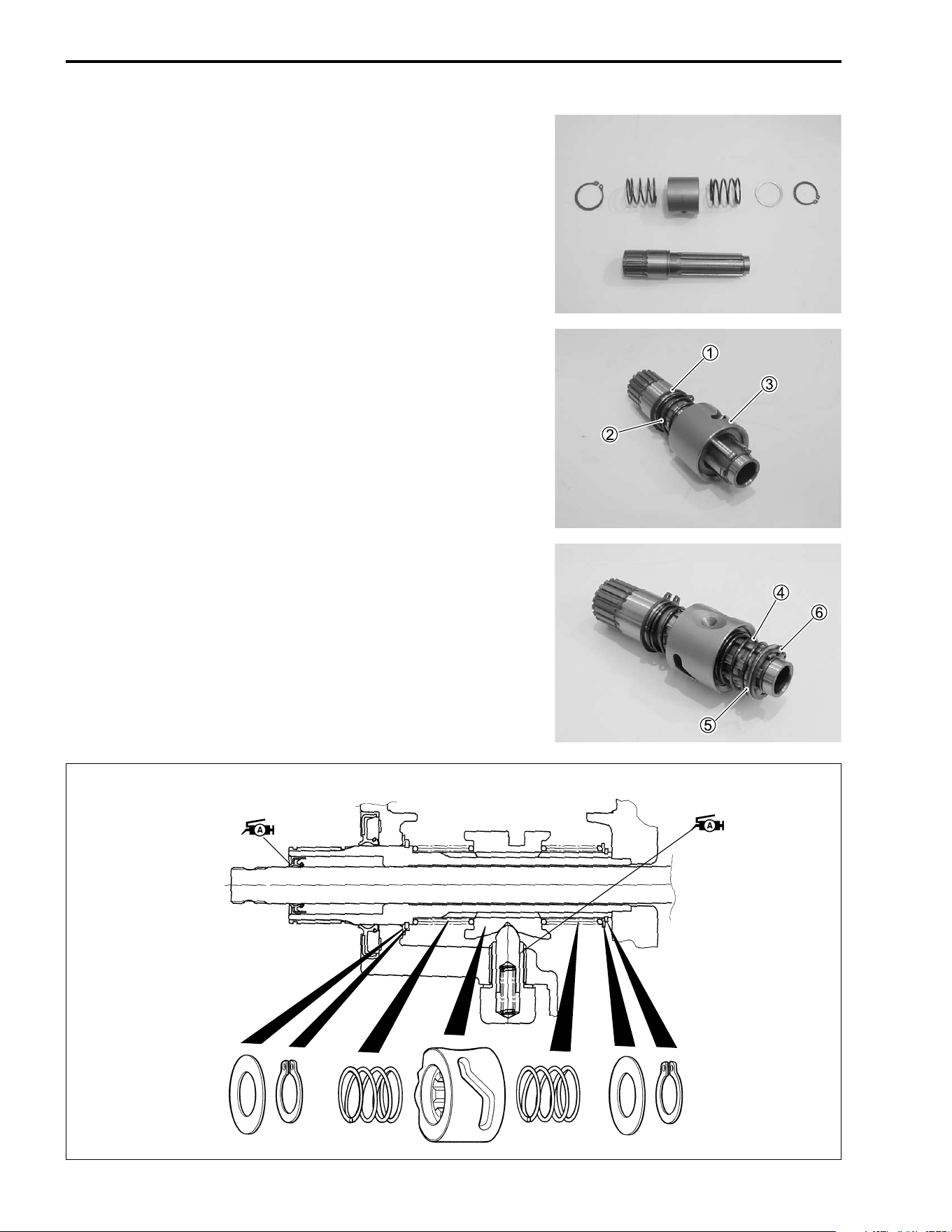
3-50 ENGINE
DISASSEMBLY
• Disassemble the transfer gearshift cam as shown.
REASSEMBLY
• Install the snap ring
1, spring
2 and gearshift cam
3.
NOTE:
The convex side of the gearshift cam
3 face lower side.
• Install the spring
4, washer
5 and snap ring
6.
ENGINE 3-51
OIL PUMP
"
& 99000-32050: THREAD LOCK “1342”
CRANKCASE
OIL SUMP FILTER
• Remove the oil sump filter cover
1.
• Remove the oil sump filter
2.
• Clean the oil sump filter using compressed air.
• When installing the O-ring, apply grease to it.
' 99000-25030: SUZUKI SUPER GREASE “A” (USA)
99000-25010: SUZUKI SUPER GREASE “A” (Others)
The oil pump case securing screw is applied with
SUZUKI THREAD LOCK “1342”. If an attempt is made
to overhaul the pump assembly, the screw may be
damaged. Only the oil pump unit is available as a
replacement.
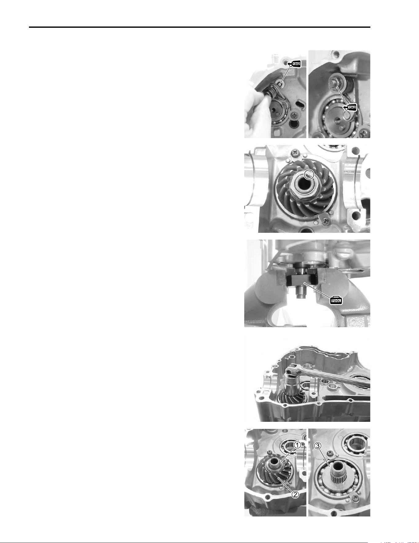
3-52 ENGINE
GEARSHIFT CAM STOPPER
• Apply a small quantity of THREAD LOCK “1342” to the thread
and tighten the gearshift cam stopper to the specified torque.
& 99000-32050: THREAD LOCK “1342”
# Gearshift cam stopper: 10 N·m (1.0 kgf-m, 7.0 lb-ft)
DRIVE BEVEL GEAR DISASSEMBLY
• Using a chisel, unlock the nut.
• Hold the output shaft with the special tool.
( 09930-73150: Output shaft holder
• Remove the drive bevel gear nut.
• Remove the washer
1 and drive bevel gear
2.
• Remove the shim
3.
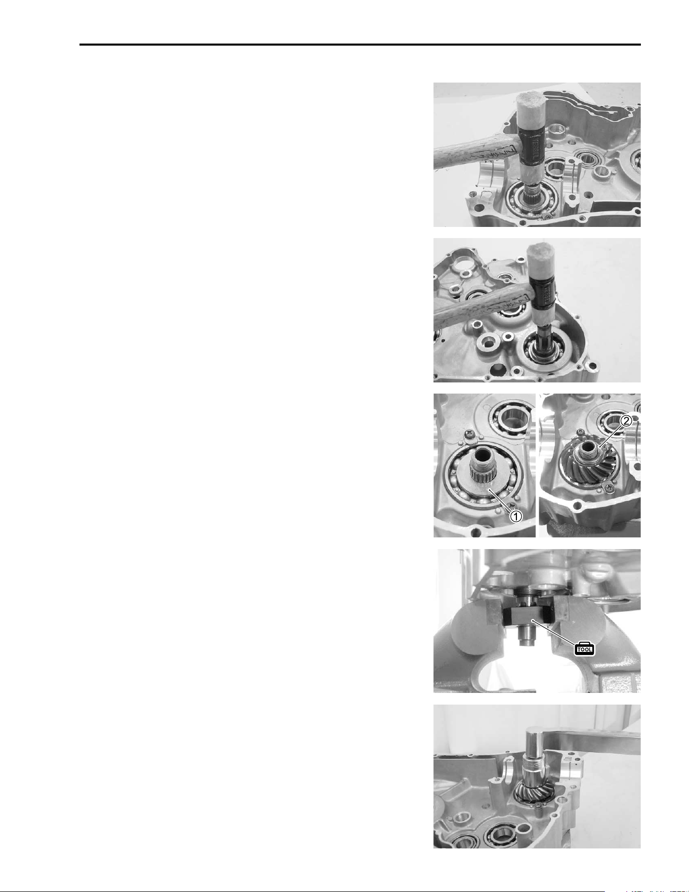
ENGINE 3-53
• Remove the output shaft with a plastic mallet.
DRIVE BEVEL GEAR REASSEMBLY
• Install the output shaft with a plastic mallet.
• Install the shim
1.
• Install the drive bevel gear and washer
2.
• Hold the output shaft with the special tool.
( 09930-73150: Output shaft holder
• Tighten the drive bevel gear nut to the specified torque.
# Drive bevel gear nut: 100 N·m (10.0 kgf-m, 72.5 lb-ft)
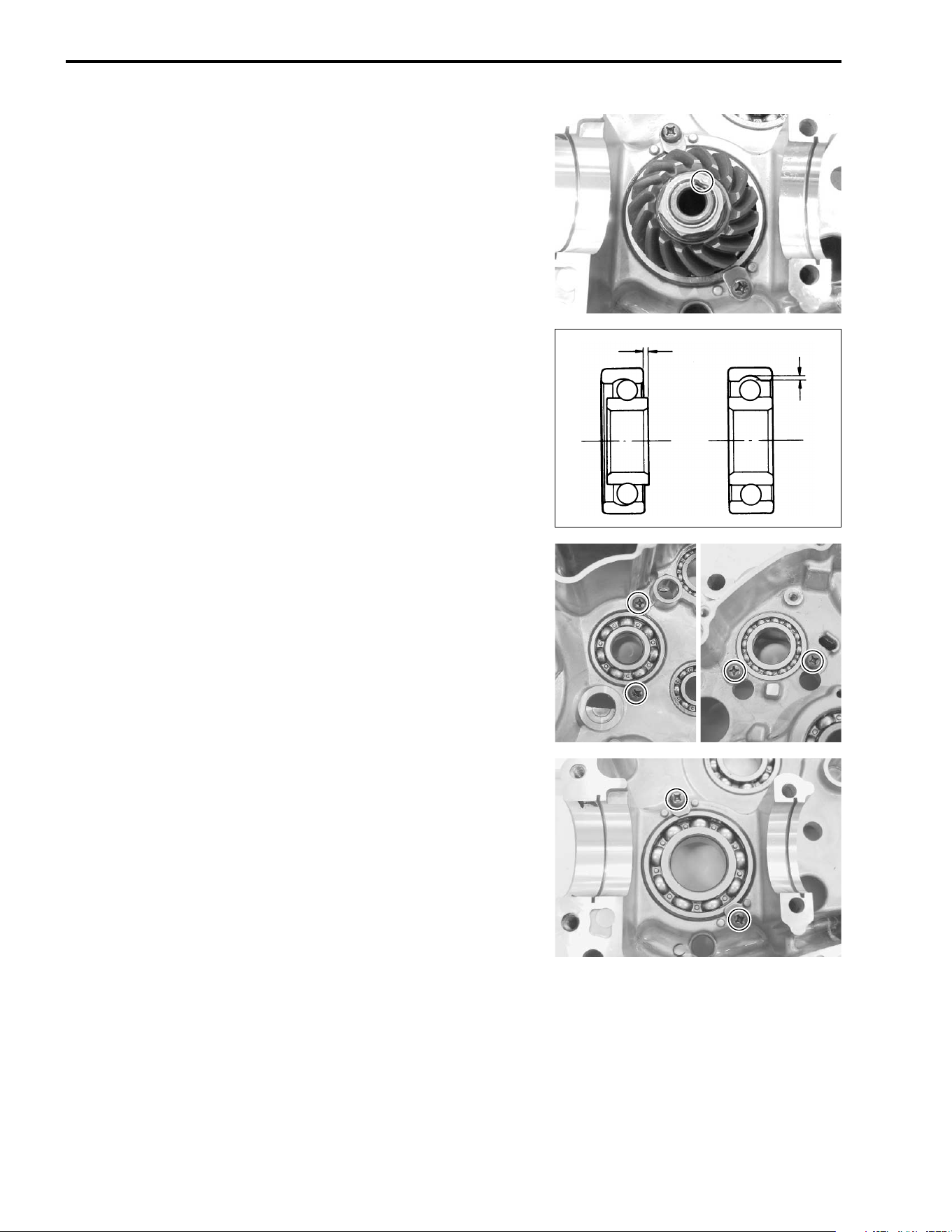
3-54 ENGINE
• Stake the nut with a center punch.
BEARING INSPECTION
Rotate the bearing inner race by finger to inspect for abnormal
play, noise and smooth rotation while the bearings are in the
crankcase.
Replace the bearing in the following procedure if there is any-
thing unusual.
BEARING DISASSEMBLY
• Remove the bearing retainers.
Play
Play
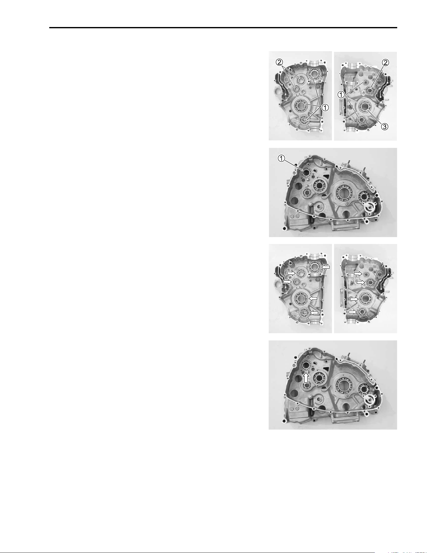
ENGINE 3-55
• Remove the bearing with the special tool.
( 09921-20210: Bearing remover
1
09923-74510: Bearing remover
2
09941-64511: Bearing remover
3
09930-30104: Sliding shaft
NOTE:
If there is no abnormal noise, the bearing removal is not neces-
sary.
BEARING REASEMBLY
• Install the bearing with the special tool.
( 09913-70210: Bearing installer set
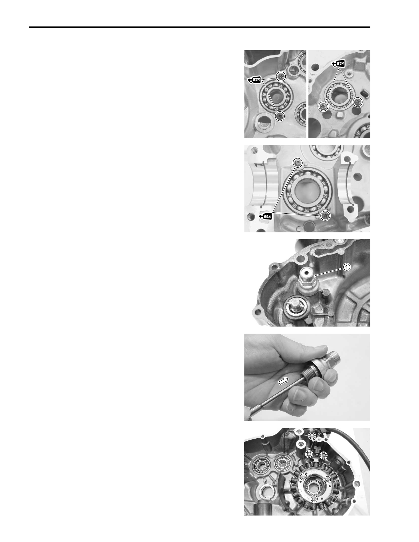
3-56 ENGINE
• Install the bearing retainers.
NOTE:
When installing the bearing retainers, apply a small quantity of
THREAD LOCK to the screws.
& 09900-32050: THREAD LOCK “1342”
OIL PRESSURE REGULATOR
• Remove the oil pressure regulator
1.
• When installing the oil pressure regulator
1, tighten it to the
specified torque.
# Oil pressure regulator: 28 N·m (2.8 kgf-m, 20.0 lb-ft)
• Check the operation of the oil pressure regulator by pushing
the piston with an appropriately shaped tool. If the piston does
not operate, replace the oil pressure regulator with a new one.
GENERATOR COVER
DISASSEMBLY
• Remove the generator stator.
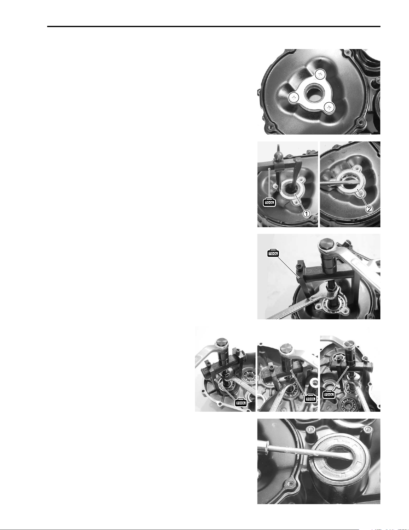
ENGINE 3-57
• Remove the oil seal retainer.
• Remove the oil seal
1 with the special tool.
( 09913-50121: Oil seal remover
• Remove the spacer
2.
• Remove the bearing with the special tool.
( 09921-20240: Bearing remover set
NOTE:
If there is no abnormal noise, the bearing removal is not neces-
sary.
• Remove the oil seal.
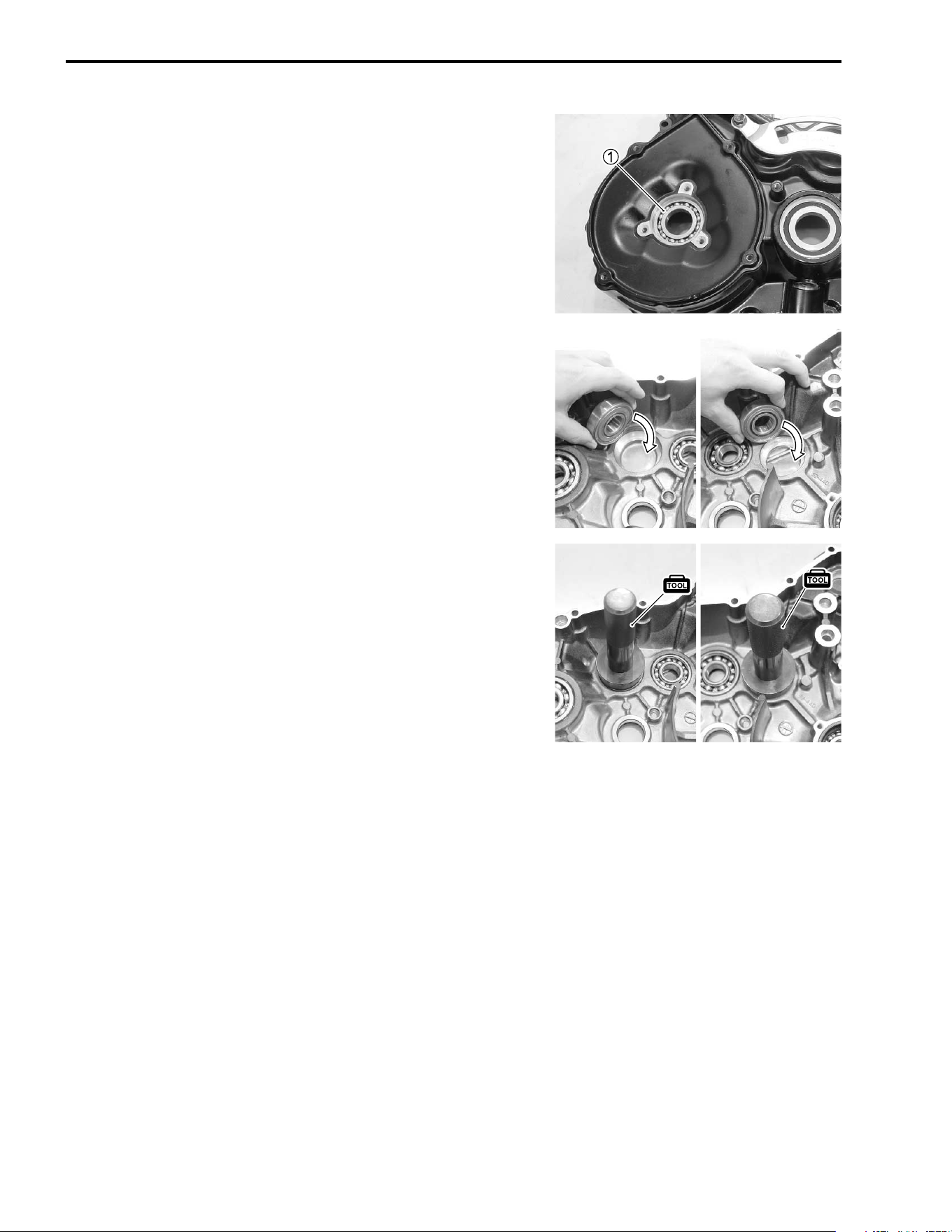
3-58 ENGINE
REASSEMBLY
• Install the bearing
1 with the special tool.
( 09913-70210: Bearing installer set
NOTE:
The sealed side of the bearing must face to crankcase.
• Install the bearing with the special tool.
( 09913-70210: Bearing installer set
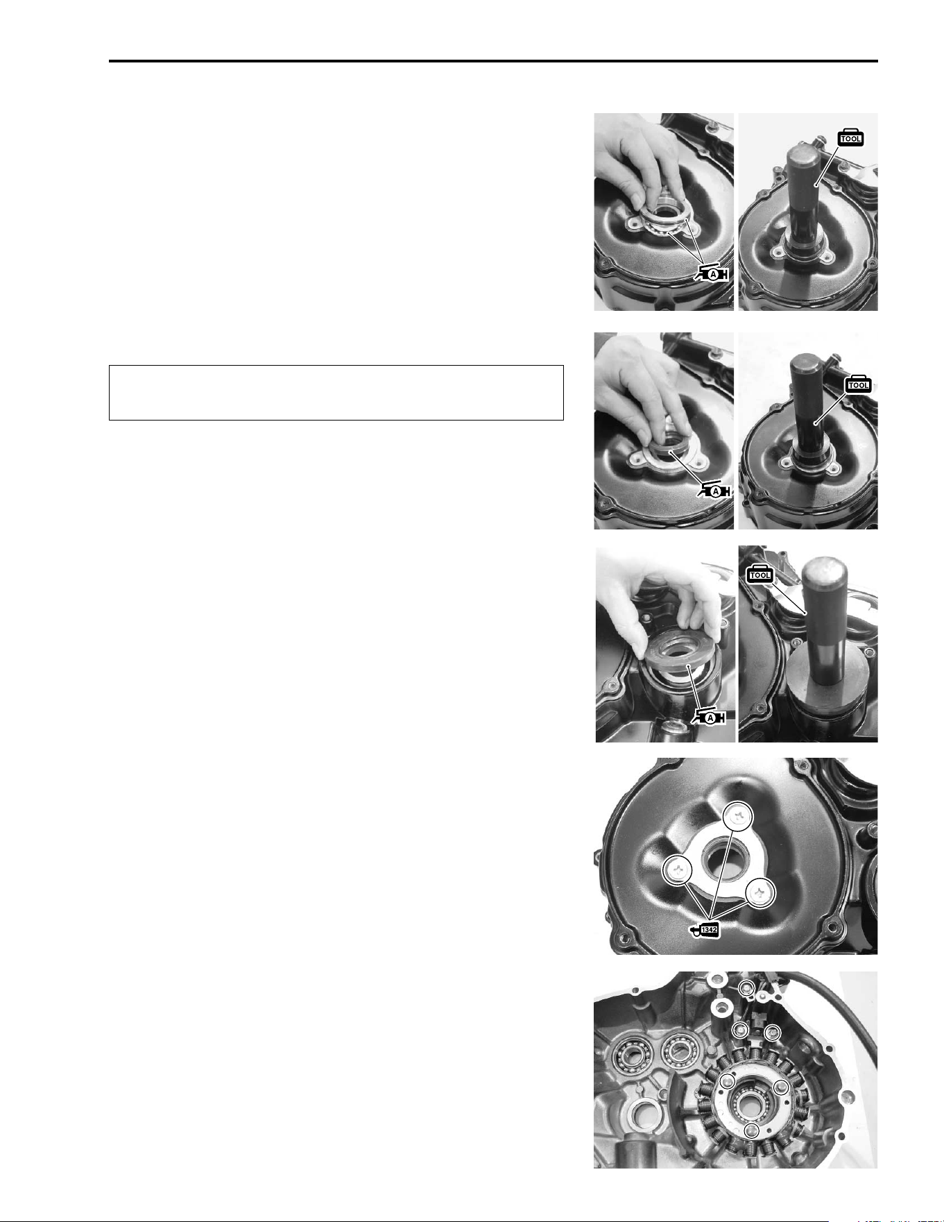
ENGINE 3-59
• Apply SUZUKI SUPER GREASE “A” to the bearing, O-ring
and oil seal lip.
• Install the oil seal with the special tool.
( 09913-70210: Bearing installer set
NOTE:
When installing the oil seals, the stamped mark on the oil seal
faces to the special tool.
' 99000-25030: SUZUKI SUPER GREASE “A” (USA)
99000-25010:SUZUKI SUPER GREASE “A” (Others)
"
• Apply a small quantity of THREAD LOCK to the screws and
install the bearing retainer.
& 99000-32050: THREAD LOCK “1342”
• Install the generator stator.
Replace the removed oil seal and O-ring with new
ones.
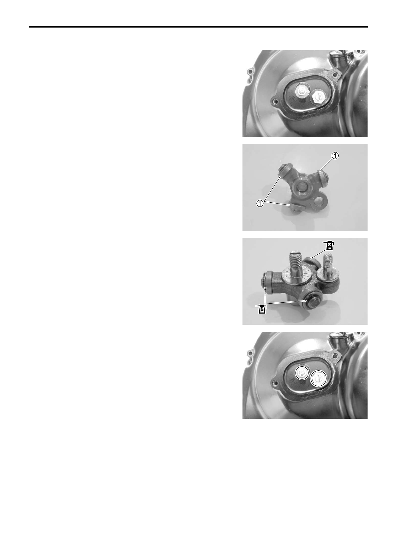
3-60 ENGINE
CLUTCH COVER
DISASSEMBLY
• Remove the clutch release mechanism.
INSPECTION
Rotate the rollers
1 by hand to inspect for an abnormal noise
and a smooth rotation. Replace the clutch release roller assem-
bly if there is anything unusual.
REASSEMBLY
• Fit the adjuster bolts as shown.
• Apply engine oil to the roller shafts.
• Tighten the adjuster nuts temporarily.
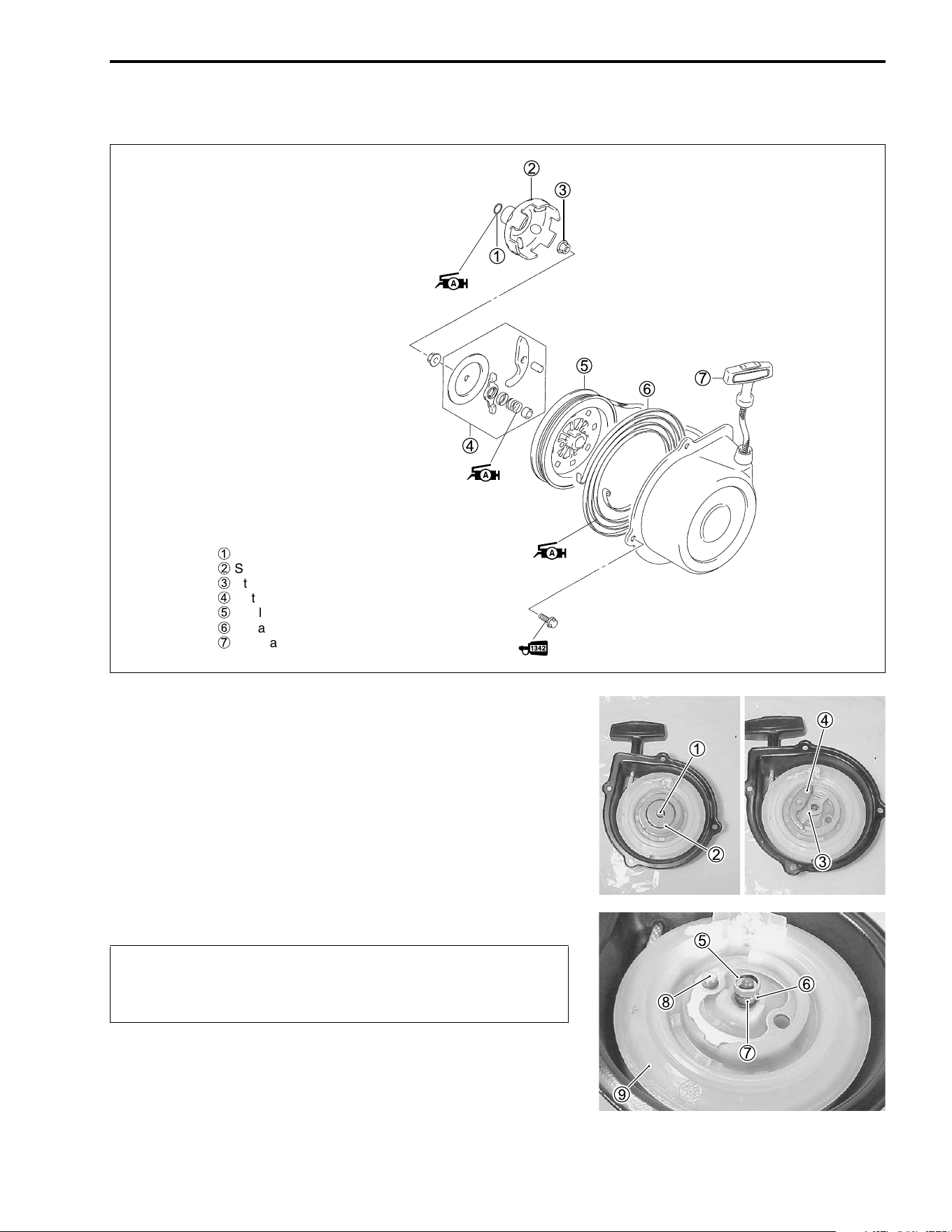
ENGINE 3-61
RECOIL STARTER
DISASSEMBLY
• After removing the nut
1, take out the recoil starter related
parts from the housing.
1 Nut
6 Spring
2 Friction plate
7 Spacer
3 Ratchet guide
8 Pin
4 Ratchet
9 Reel
5 Spring cover
)
1
O-ring
2
Starter cup
3
Starter cup nut
4
Ratchet set
5
Reel
6
Spiral spring
7
Rope assembly
Wear hand and eye protection when removing the reel,
since the spring may quickly unwind and cause an
injury.
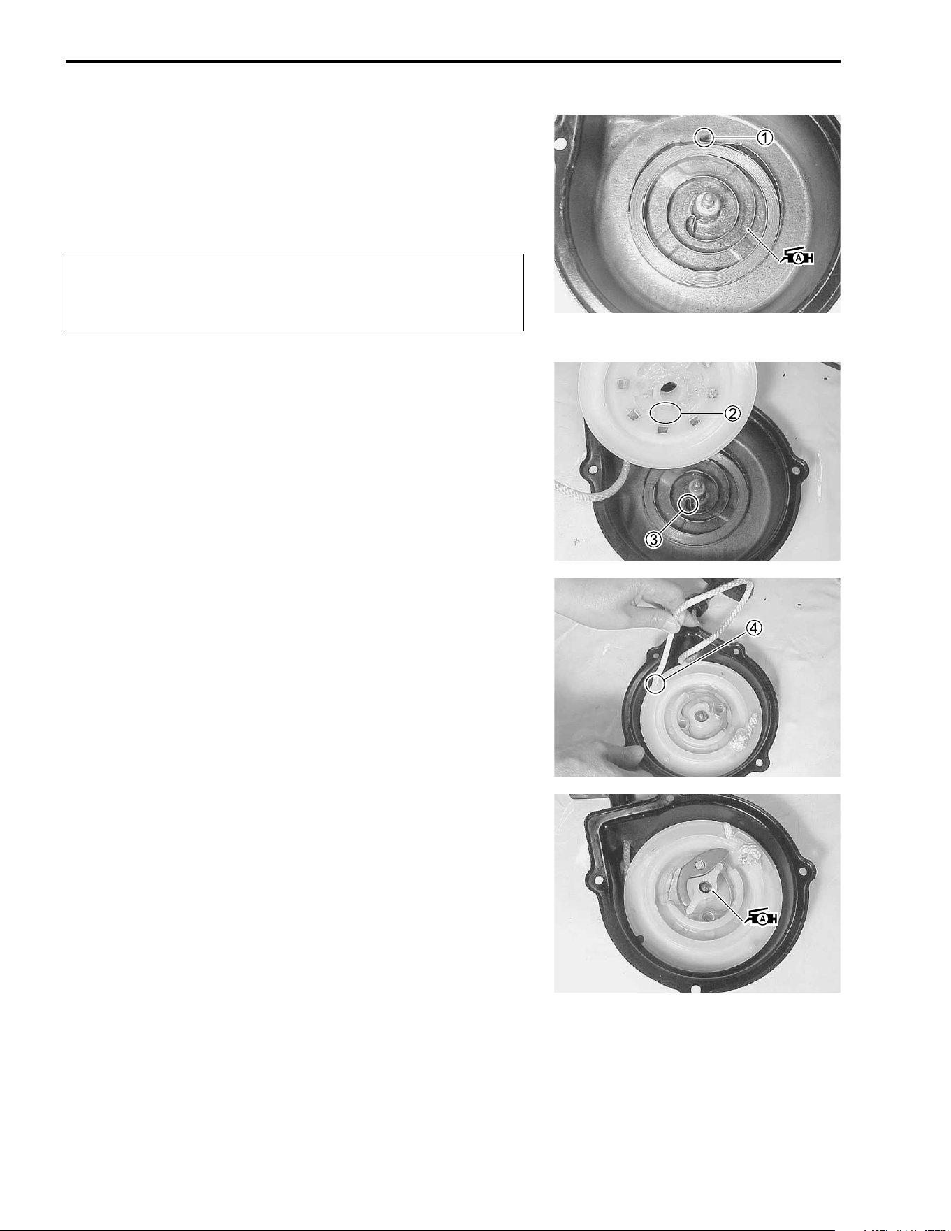
3-62 ENGINE
REASSEMBLY
Reassemble the recoil starter in the reverse order of disassem-
bly. Pay attention to the following points:
• When installing the spiral spring, hook the spiral spring end
1
with the recoil starter case.
)
• Apply SUZUKI SUPER GREASE “A” to the spiral spring.
' 99000-25030: SUZUKI SUPER GREASE “A” (USA)
99000-25010: SUZUKI SUPER GREASE “A” (Others)
• Turn the starter rope on the reel properly.
• After installing the spiral spring, engage the part
2 of the reel
with the spiral spring end
3.
• Hook the rope onto the hook part
4 of the reel, turn the reel
clockwise three of four times with the rope.
• Install the ratchet related parts.
NOTE:
Apply SUZUKI SUPER GREASE “A” to the shaft and ratchet.
' 99000-25030: SUZUKI SUPER GREASE “A” (USA)
99000-25010: SUZUKI SUPER GREASE “A” (Others)
Wear hand and eye protection when installing the reel,
since the spring may quickly unwind and cause an
injury.
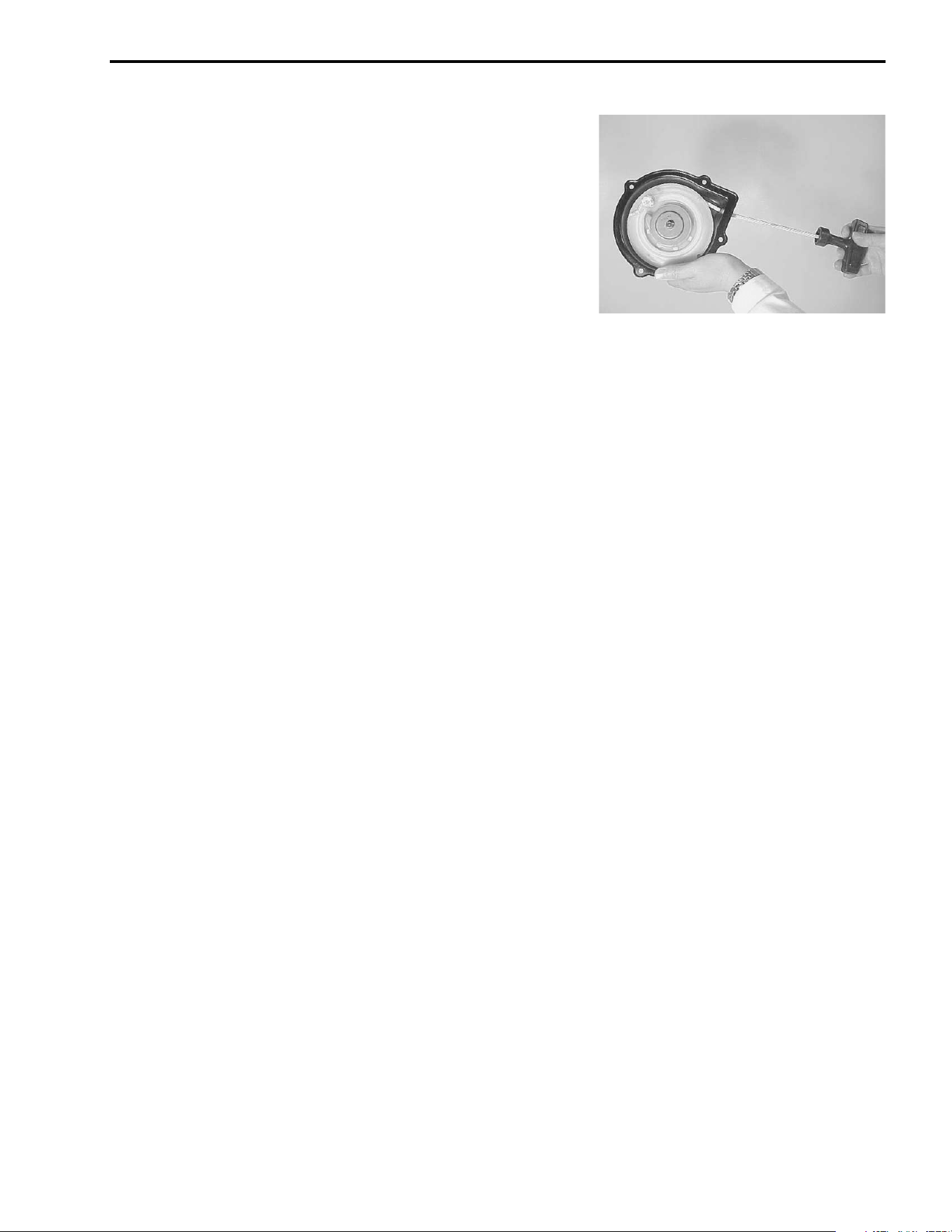
ENGINE 3-63
• Pull the rope and check that the ratchet is pushed out.
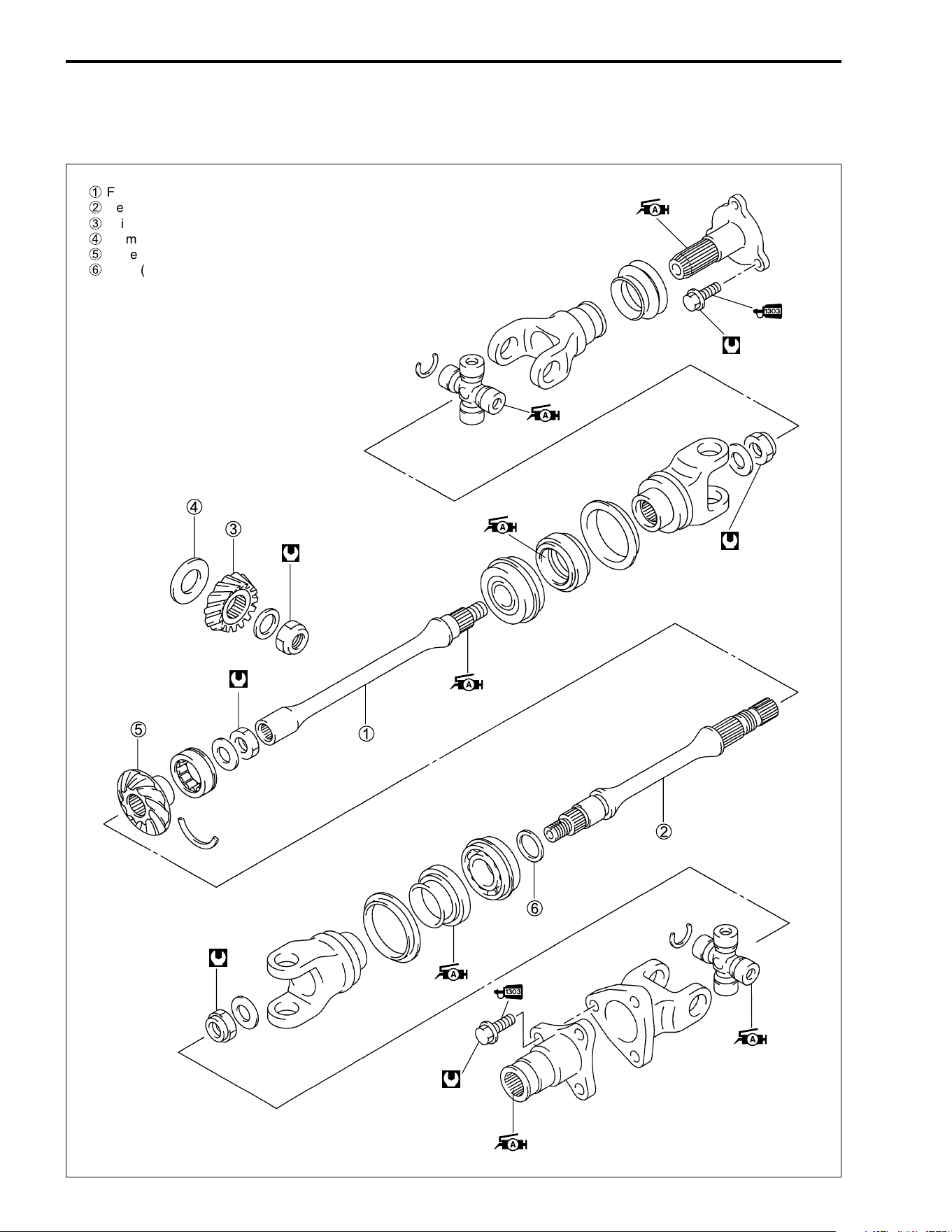
3-64 ENGINE
DRIVE TRAIN (INBOARD SIDE)
FRONT/REAR OUTPUT SHAFT
100 N·m
(10.0 kgf-m, 72.5 lb-ft)
100 N·m
10.0 kgf-m
72.5 lb-ft
100 N·m
(10.0 kgf-m, 72.5 lb-ft)
1
Front output shaft
2
Rear output shaft
3
Drive bevel gear
4
Shims (s)
5
Driven bevel gear
6
Shim (s)
( )
100 N·m
10.0 kgf-m
72.5 lb-ft
( )
30 N·m
3.0 kgf-m
21.5 lb-ft
( )
45 N·m
4.5 kgf-m
32.5 lb-ft
( )
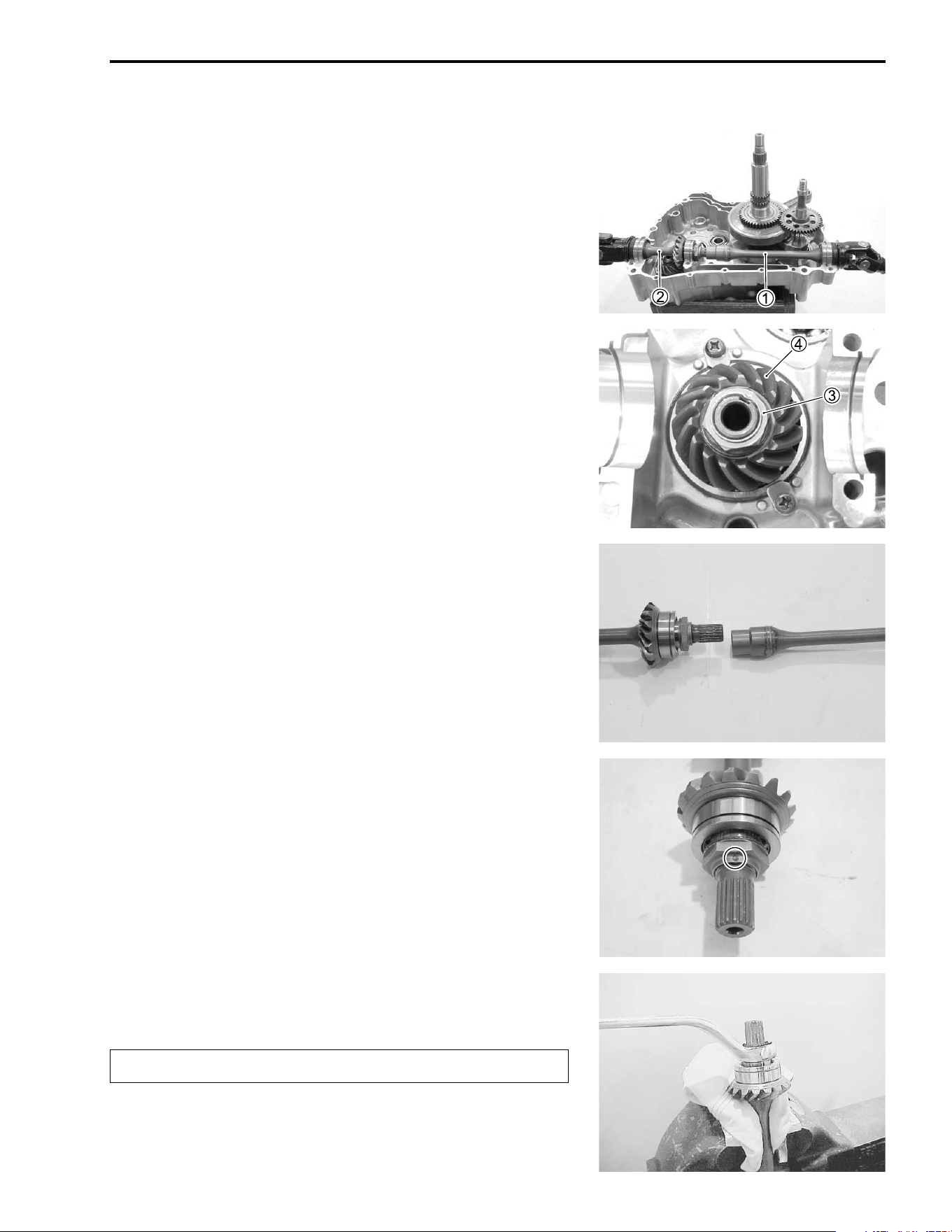
ENGINE 3-65
REMOVAL
• Remove the transmission assemblies. (!3-23)
• Remove the front output shaft
1 and rear output shaft
2.
• After removing the drive bevel gear nut
3, remove the drive
bevel gear
4. (!3-52)
• Separate the front and rear output shafts.
DISASSEMBLY
Rear output shaft
• Using a chisel and unlock the nut.
• With the rear output shaft held immovable with a vise, remove
the nut.
"
Replace the removed nut with a new one.
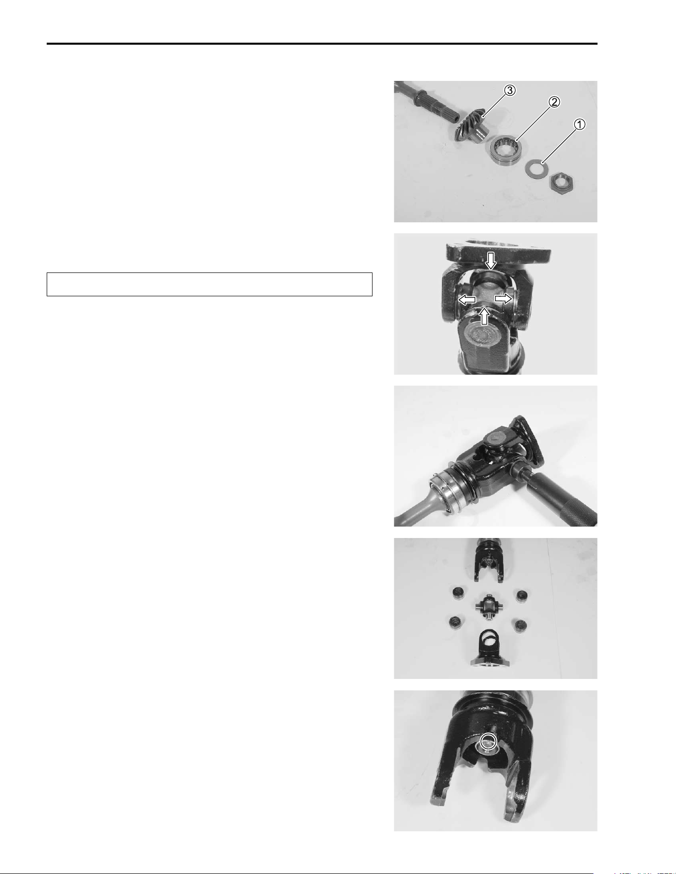
3-66 ENGINE
• Remove the washer
1, bearing
2 and driven bevel gear
3.
• Remove the C-rings from the universal joint.
"
• Remove the bearings by tapping with the special tool and
hammer.
( 09913-70210: Bearing installer set
• Remove the universal joint.
• Using a chisel and unlock the nut.
Replace the removed C-ring with a new one.
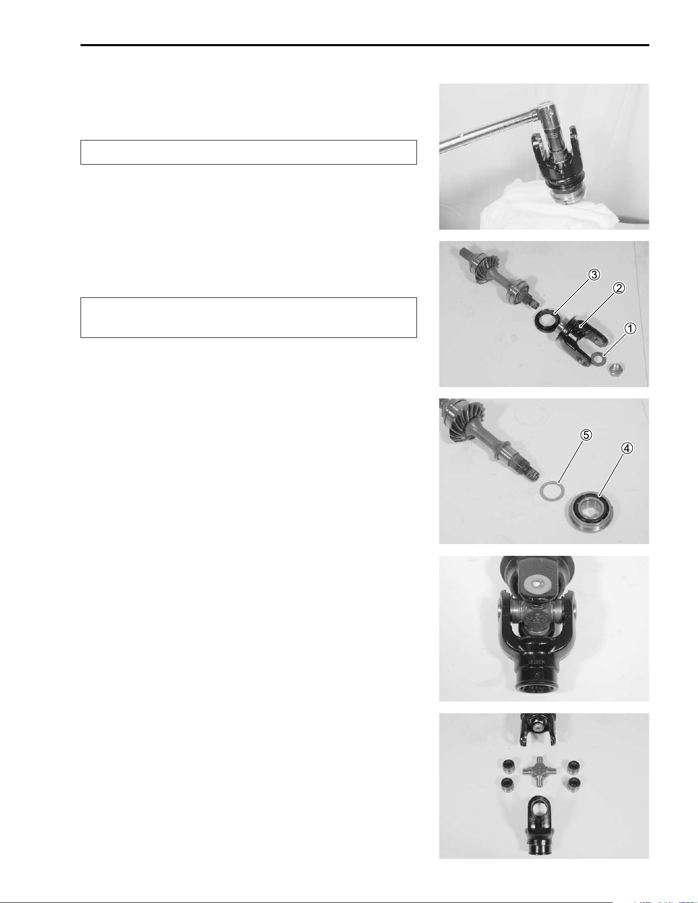
ENGINE 3-67
• With the rear output shaft held immovable with a vise, remove
the nut.
"
• Remove the washer
1, joint yoke
2, oil seal
3, bearig
4
and shim
5.
"
Front output shaft
• Remove the C-rings from the universal joint. (!3-66)
• Remove the bearing. (!3-66)
• Remove the universal joint.
Replace the removed nut with a new one.
The removed bearing and oil seal must be replaced
with the new ones.
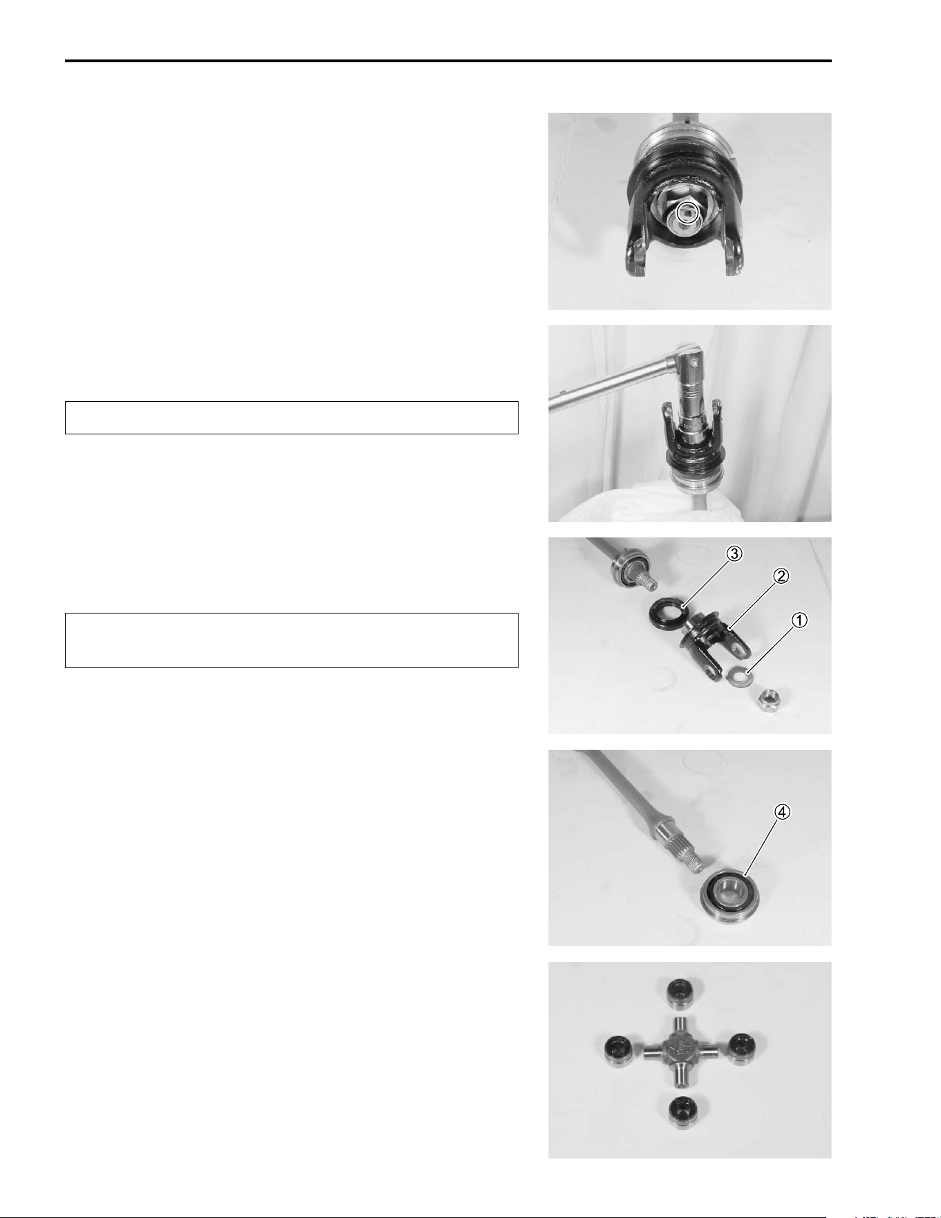
3-68 ENGINE
• Using a chisel and unlock the nut.
• With the front output shaft held immovable with a vise,
remove the nut.
"
• Remove the washer
1, joint yoke
2, oil seal
3 and bearing
4.
"
INSPECTION
Inspect the universal joint and outer surface of the bearing for
scuffing, wear and damage. If any defects are found, replace the
bearings and universal joint as a set.
Replace the removed nut with a new one.
The removed bearing and oil seal must be replaced
with the new ones.
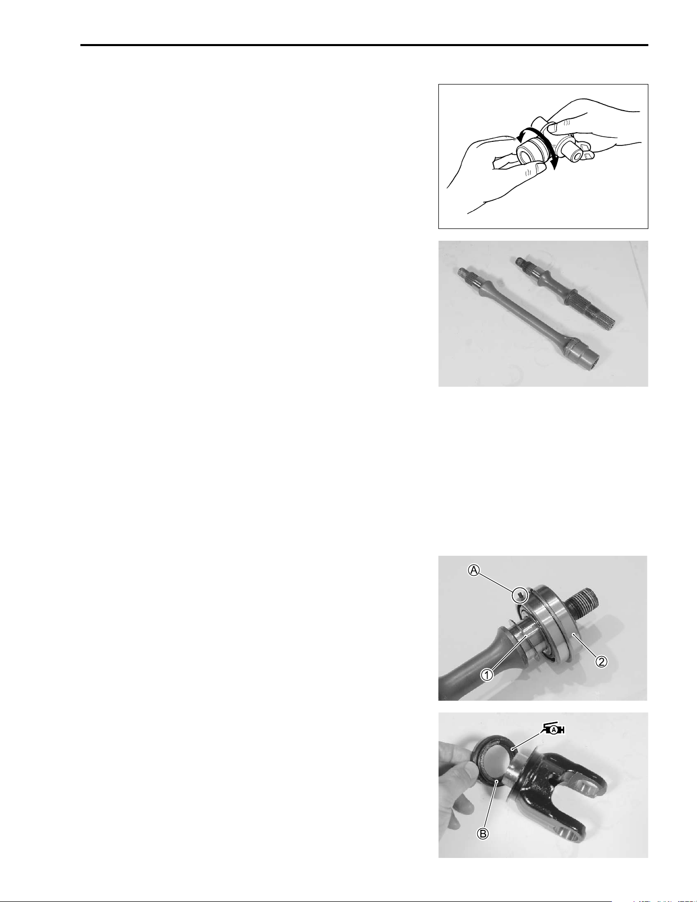
ENGINE 3-69
Insert the universal joint to the bearing and check the play by
turning the universal joint, as shown. If excessive play is noted,
replace the bearing with a new one.
Inspect the front and rear output shafts for distortion. If distortion
is found, replace the front or rear output shaft with a new one.
Inspect the drive and driven bevel gears for wear or damage. If
any wear or damage is found, replace the drive and driven bevel
gears as a set.
REASSEMBLY
Reassemble the front and rear output shafts in the reverse order
of disassembly. Pay attention to the following points:
NOTE:
Before reassembly, thoroughly clean all parts in cleaning sol-
vent.
Rear output shaft
• Install the shim
1 and bearing
2.
NOTE:
The bearing knock-pin
A should be positioned inside.
• Apply grease to the lip of the oil seal.
• Install the oil seal to the joint yoke.
' 99000-25030: SUZUKI SUPER GREASE “A” (USA)
99000-25010: SUZUKI SUPER GREASE “A” (Others)
NOTE:
The lip
B of the oil seal should be positioned joint yoke side.
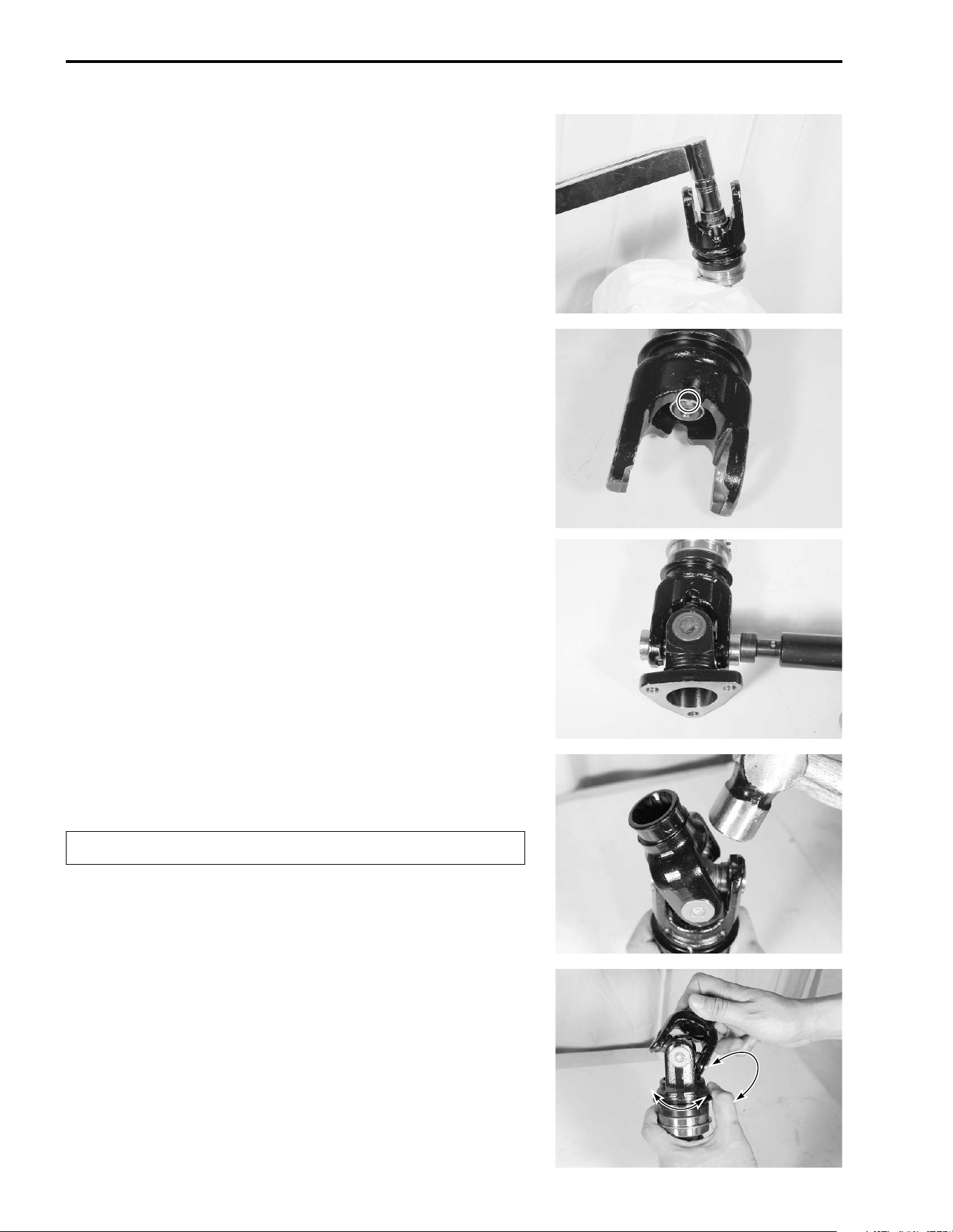
3-70 ENGINE
• With the rear output shaft held immovable with a vise, tighten
the new nut to the specified torque.
# Rear output shaft nut: 100 N·m (10.0 kgf-m, 72.5 lb-ft)
NOTE:
Do not stake a lock portion on the nut at this stage. After the
backlash and tooth contact have been checked or adjusted,
stake the nut with a center punch.
• Apply grease to the bearing and its dust seal lip.
• Install the universal joint and bearings with the special tool.
' 99000-25030: SUZUKI SUPER GREASE “A” (USA)
99000-25010: SUZUKI SUPER GREASE “A” (Others)
( 09913-70210: Bearing installer set
NOTE:
After the backlash and tooth contact have been checked or
adjusted, reassemble the universal joint.
• Install the C-rings by tapping with a copper hammer as
shown.
"
• After reassembling the universal joint, check the joint move-
ment smoothly. If a large resistance is felt to movement, tap
the bearing with a plastic mallet lightly.
Replace the removed C-ring with a new one.
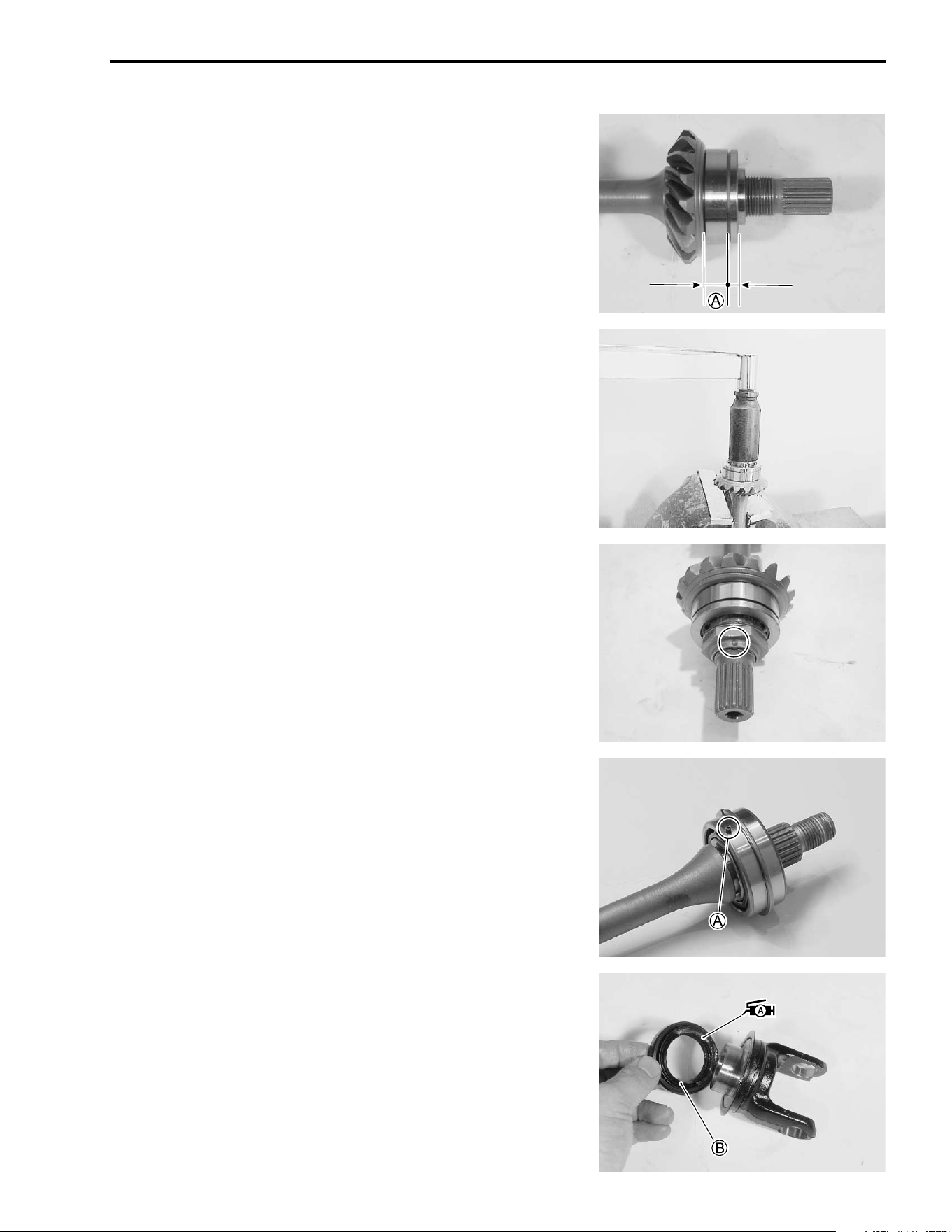
ENGINE 3-71
• Install the driven bevel gear, bearing, washer and nut.
NOTE:
The wider side
A of the bearing should be positioned driven
bevel gear side.
• With the rear output shaft held immovable with a vise, tighten
the new nut to the specified torque.
# Final driven bevel nut: 100 N·m (10.0 kgf-m, 72.5 lb-ft)
• Stake the nut with a center punch.
Front output shaft
• Install the bearing to the shaft.
NOTE:
The bearing knock-pin
A should be positioned inside.
• Apply grease to the lip of the oil seal.
• Install the oil seal to the joint yoke.
' 99000-25030: SUZUKI SUPER GREASE “A” (USA)
99000-25010: SUZUKI SUPER GREASE “A” (Others)
NOTE:
The lip
B of the oil seal should be positioned joint yoke side.
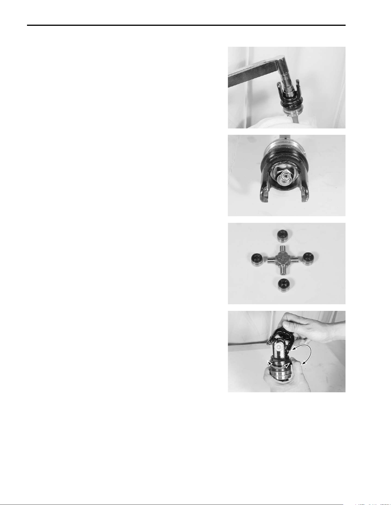
3-72 ENGINE
• With the front output shaft held immovable with a vise, tighten
the new nut to the specified torque.
# Front output shaft nut: 100 N·m (10.0 kgf-m, 72.5 lb-ft)
• Stake the nut with a center punch.
• Apply grease to the bearing and dust seal lip.
• Install the universal joint and bearings with the special tool.
(!3-70)
• Install the C-rings by tapping with a copper hammer.
(!3-70)
' 99000-25030: SUZUKI SUPER GREASE “A” (USA)
99000-25010: SUZUKI SUPER GREASE “A” (Others)
( 09913-70210: Bearing installer set
NOTE:
Reassemble the universal joint in the same manner as the rear
one. (!3-70)
• After reassembling the universal joint, check the joint move-
ment smoothly. If a large resistance is felt to movement, tap
the bearing with a plastic mallet lightly.

ENGINE 3-73
SHIM ADJUSTMENT
BACKLASH
• Install the drive bevel gear. (!3-52)
• Place the front and rear output shafts on the crankcase and
hold bearings with the special tool.
( 09921-21910: Bearing holder
• Set a dial gauge as shown on the drive bevel gear.
Measure the backlash by turning the drive bevel gear shaft in
each direction, reading the total backlash on the dial gauge. If
the backlash is not within specification, the shim must be
changed and the backlash should be re-checked until correct.
Refer to the chart at the right for appropriate shim thickness.
% Bevel gear backlash
Standard: 0.03 – 0.15 mm (0.001 – 0.006 in)
NOTE:
Adjust the backlash by referring to the chart at the right and
using the thickness of the removed shims as a guide.
Backlash Shim adjustment
Under 0.03 mm
(0.001 in)
Increase shim thickness
0.03 – 0.15 mm
(0.001 – 0.006 in)
Correct
Over 0.15 mm
(0.006 in)
Decrease shim thickness
Part No.
Shim thickness
For driven bevel gear (
:
3-76)
09181-25051
09181-25052
09181-25053
09181-25054
09181-25055
09181-25056
09181-25057
09181-25058
09181-25059
09181-25060
09181-25061
09181-25062
09181-25063
0.60 mm (0.0236 in)
0.65 mm (0.0256 in)
0.70 mm (0.0276 in)
0.75 mm (0.0295 in)
0.80 mm (0.0315 in)
0.85 mm (0.0335 in)
0.90 mm (0.0354 in)
0.95 mm (0.0374 in)
1.00 mm (0.0394 in)
1.05 mm (0.0413 in)
1.10 mm (0.0433 in)
1.15 mm (0.0453 in)
1.20 mm (0.0472 in)
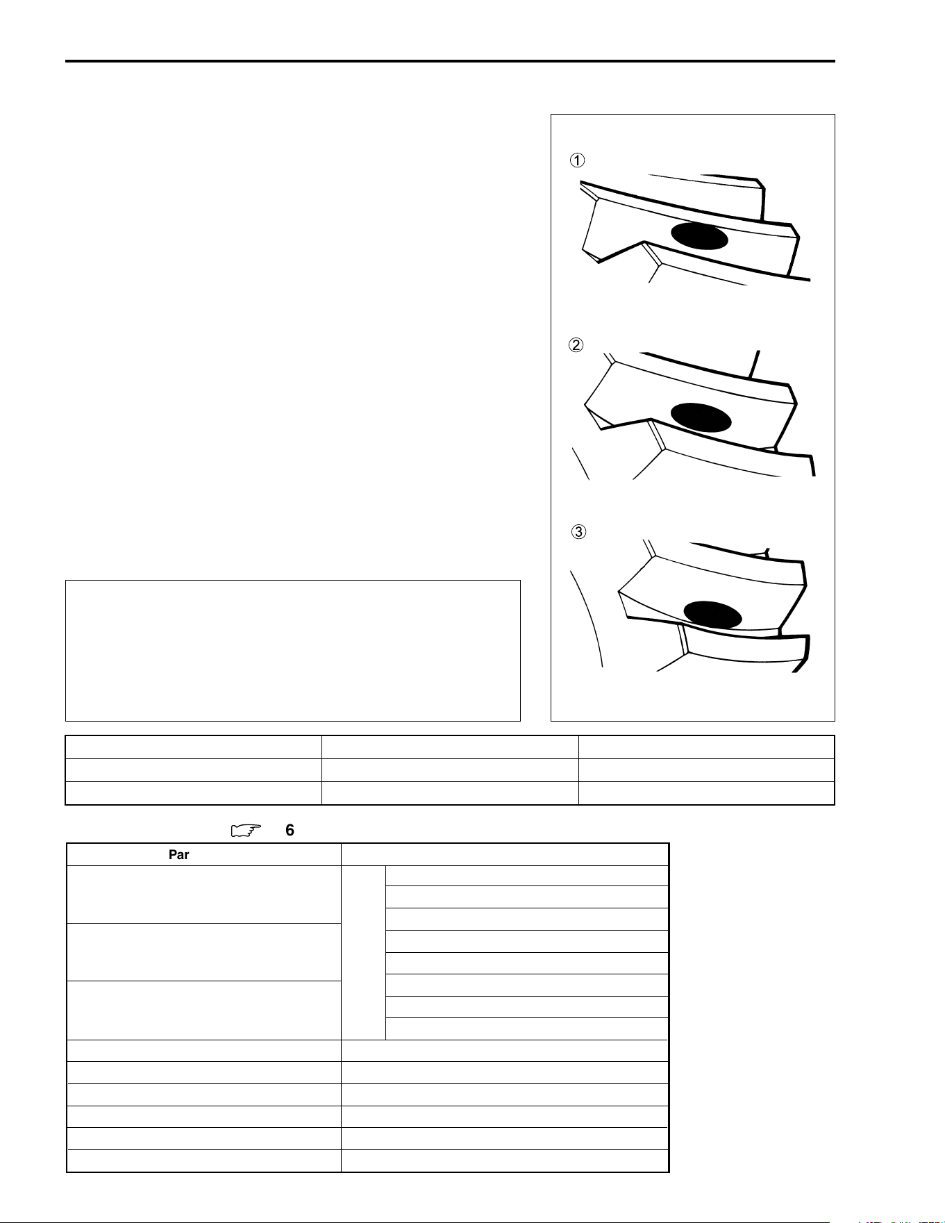
3-74 ENGINE
TOOTH CONTACT
After backlash adjustment is carried out, the tooth contact must
be checked. Pay attention to the following procedures:
• Remove the front and rear output shafts from the crankcase.
• Clean and degrease several teeth of the drive and driven
bevel gears.
• Apply a coating of machinist’s layout dye or paste to several
teeth of the driven bevel gear.
• Install the front and rear output shafts.
• Rotate the driven bevel gear several turns in both directions.
• Remove the output shafts and inspect the coated teeth of the
drive bevel gear. The tooth contact pattern should be as
shown in
1,
2 and
3.
• If tooth contact is found to be correct (example
2), go to the
FINAL ASSEMBLY section on p.3-75 to complete installation.
1 Incorrect (contact at tooth top)
2 Correct
3 Incorrect (contact at tooth root)
• If tooth contact is found to be incorrect (examples
1 and
3),
the shim thickness between the drive bevel gear and driven
bevel gear must be changed and the tooth contact rechecked
until correct.
"
Make sure to check the backlash after the tooth con-
tact has been adjusted, since it may have changed.
Adjust the tooth contact and backlash until they are
both within specification. If the correct tooth contact
cannot be maintained when adjusting the backlash,
replace the drive and driven bevel gears.
Tooth contact
Drive bevel gear shim adjustment
Driven bevel gear shim adjustment
Contact at tooth top
1 Increase shim thickness Decrease shim thickness
Contact at tooth root
3 Decrease shim thickness Increase shim thickness
1
2
3
Part No.
Shim thickness
For drive bevel gear (
:
3-76)
24935-19B00-025: 0.25 mm (0.0098 in)
24935-19B00-030: 0.30 mm (0.0118 in)
24935-19B00-035: 0.35 mm (0.0138 in)
24935-19B00-115
0.30+0.30=0.60 mm (0.0236 in)
0.30+0.35=0.65 mm (0.0256 in)
0.35+0.35=0.70 mm (0.0276 in)
0.25+0.25+0.25=0.75 mm (0.0295 in)
0.25+0.25+0.30=0.80 mm (0.0315 in)
0.25+0.25+0.35=0.85 mm (0.0335 in)
0.90 mm (0.0354 in)
0.95 mm (0.0374 in)
1.00 mm (0.0394 in)
1.05 mm (0.0413 in)
1.10 mm (0.0433 in)
1.15 mm (0.0453 in)
24935-19B00-110
24935-19B00-105
24935-19B00-100
24935-19B00-095
24935-19B00-090
Combined shim
0.25+0.25=0.50 mm (0.0197 in)
0.25+0.30=0.55 mm (0.0217 in)
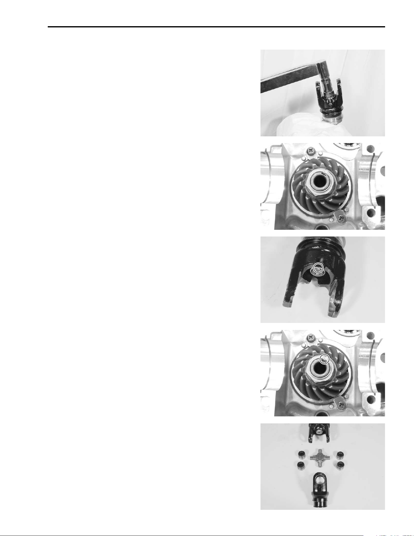
ENGINE 3-75
FINAL ASSEMBLY
• After adjusting the gear backlash and tooth contact correctly,
remove the front and rear output shafts and drive bevel gear.
• Clean off any machinist’s dye or paste from the gear teeth,
and lubricate the teeth with engine oil.
• Tighten the rear output shaft nut and drive bevel gear nut to
the specified torque.
# Rear output shaft nut: 100 N·m (10.0 kgf-m, 72.5 lb-ft)
Drive bevel gear nut: 100 N·m (10.0 kgf-m, 72.5 lb-ft)
( 09930-73150: Output shaft holder (!3-52)
• Stake the collar of the nut
1 into the notch in the shaft.
\
NOTE:
After the backlash and tooth contact have been checked or
adjusted, reassemble the universal joint. (!3-70)

3-76 ENGINE
REASSEMBLY INFORMATION
ITEM N·m kgf-m lb-ft
123
100 10.0 72.5
@
Part No.
Shim thickness
List of shims
B
available for the drive bevel gear side.
24935-19B00-025: 0.25 mm (0.0098 in)
24935-19B00-030: 0.30 mm (0.0118 in)
24935-19B00-035: 0.35 mm (0.0138 in)
24935-19B00-115
0.30+0.30=0.60 mm (0.0236 in)
0.30+0.35=0.65 mm (0.0256 in)
0.35+0.35=0.70 mm (0.0276 in)
0.25+0.25+0.25=0.75 mm (0.0295 in)
0.25+0.25+0.30=0.80 mm (0.0315 in)
0.25+0.25+0.35=0.85 mm (0.0335 in)
0.90 mm (0.0354 in)
0.95 mm (0.0374 in)
1.00 mm (0.0394 in)
1.05 mm (0.0413 in)
1.10 mm (0.0433 in)
1.15 mm (0.0453 in)
24935-19B00-110
24935-19B00-105
24935-19B00-100
24935-19B00-095
24935-19B00-090
Combined shim
0.25+0.25=0.50 mm (0.0197 in)
0.25+0.30=0.55 mm (0.0217 in)
Part No.
Shim thickness
List of shims
A
available for the driven bevel
gear side.
09181-25051
09181-25052
09181-25053
09181-25054
09181-25055
09181-25056
09181-25057
09181-25058
09181-25059
09181-25060
09181-25061
09181-25062
09181-25063
0.60 mm (0.0236 in)
0.65 mm (0.0256 in)
0.70 mm (0.0276 in)
0.75 mm (0.0295 in)
0.80 mm (0.0315 in)
0.85 mm (0.0335 in)
0.90 mm (0.0354 in)
0.95 mm (0.0374 in)
1.00 mm (0.0394 in)
1.05 mm (0.0413 in)
1.10 mm (0.0433 in)
1.15 mm (0.0453 in)
1.20 mm (0.0472 in)
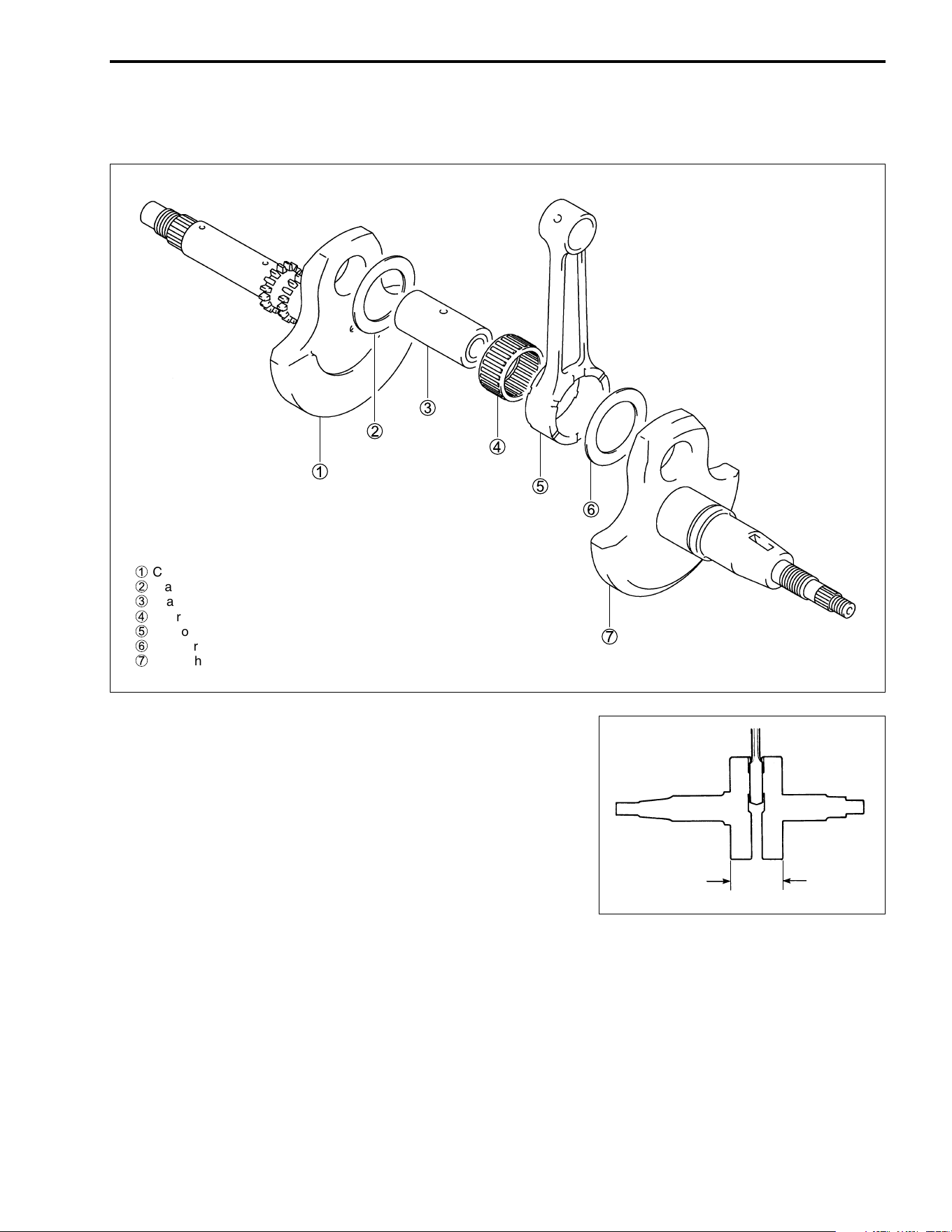
ENGINE 3-77
CRANKSHAFT
DISASSEMBLY
REASSEMBLY
• Determine the width between the webs referring to the figure
when rebuilding the crankshaft.
% Crank web to web width
Standard: 70.9 – 71.1 mm (2.791 – 2.799 in)
1
Crankshaft (R)
2
Washer
3
Crank pin
4
Bearing
5
Conrod
6
Washer
7
Crankshaft (L)
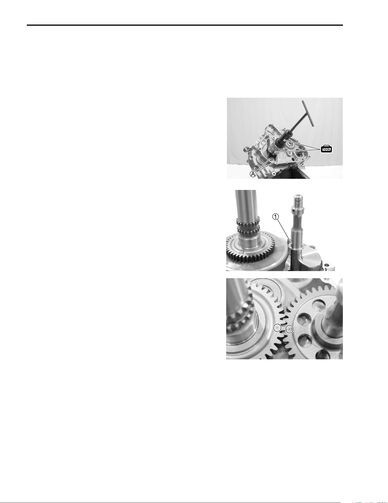
3-78 ENGINE
ENGINE REASSEMBLY
Reassemble the engine in the reverse order of disassembly.
Pay special attention to the following points:
NOTE:
Apply engine oil to each running and sliding part before reas-
sembling.
ENGINE BOTTOM SIDE
CRANKSHAFT
• When mounting the crankshaft in the crankcase, it is neces-
sary to pull its left end into the crankcase with the special tool.
NOTE:
Use the front fork oil seal installer and suitable bars
A as an
attachment.
( 09910-32812: Crankshaft installer
09940-52861: Front fork oil seal installer
BALANCER
• Install the balancershaft.
• Install the key
1.
• Install the balancershaft driven gear by aligning the punched
marks.
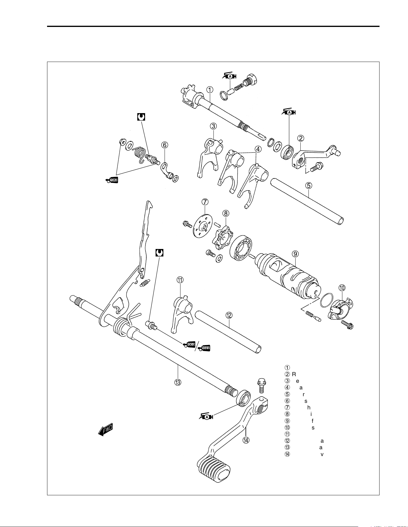
ENGINE 3-79
GEARSHIFT CAM AND FORK
1
Reverse shift cam
2
Reverse gearshift arm
3
Reverse gearshift fork
4
Gearshift fork No. 1
5
Gearshift fork shaft
6
Gearshift cam stopper
7
Gearshift cam plate guide
8
Gearshift cam plate
9
Gearshift cam
0
Neutral switch
A
Gearshift fork No. 2
B
Reverse gearshift fork shaft
C
Gearshift cam shaft
D
Gearshift lever
10 N
.
m
(1.0 kgf
.
m,
7.0 lb-ft)
19 N
.
m
(1.9 kgf
.
m,
13.5 lb-ft)
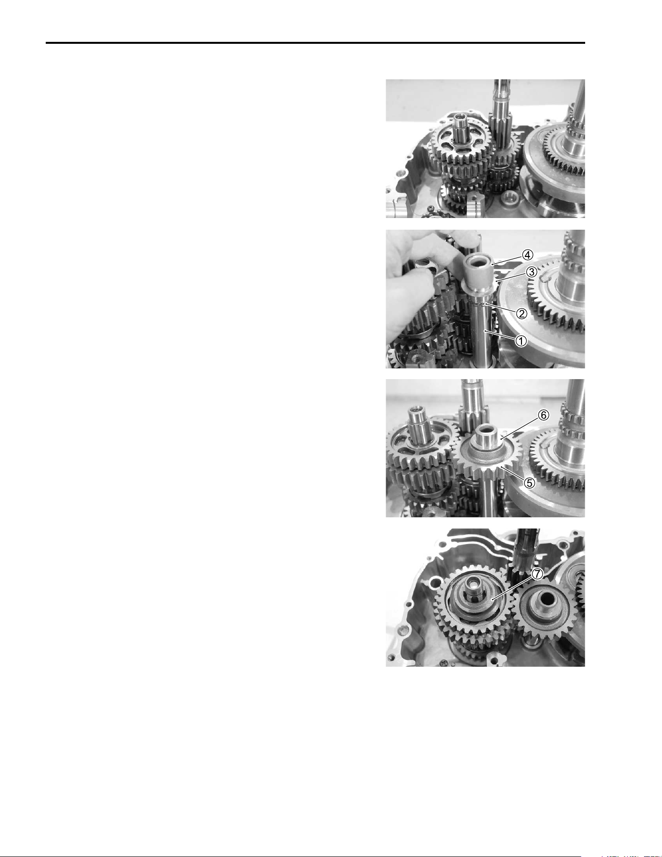
3-80 ENGINE
• Install the driveshaft and countershaft.
• Install the reverse idle gear shaft
1.
• Install the snap ring
2, washer
3 and spacer
4.
• Install the reverse idle gear
5 and washer
6.
• Install the reverse dog
7 on the driveshaft.
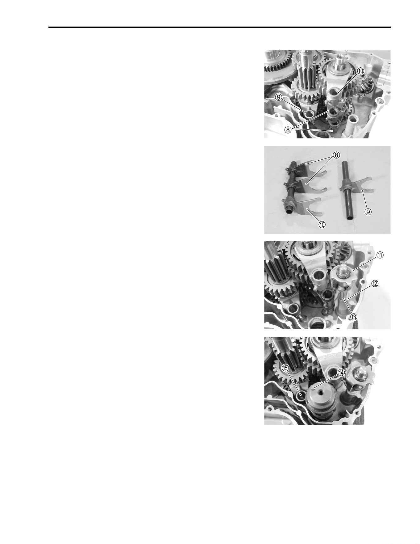
ENGINE 3-81
• Fit the gearshift forks No. 1
8, No. 2
9, and reverse gearshift
fork
0 into the gearshifting grooves.
NOTE:
Three kinds of gearshifting forks are used. They resemble each
other very closely in external appearance and configuration.
8: Gearshift fork No. 1
9: Gearshift fork No. 2
0: Reverse gearshift fork
• Install the reverse shift cam
A.
NOTE:
When installing the reverse shift cam, be sure to install the
washer
B and snap ring
C.
• Install the gearshift cam.
NOTE:
When installing the gearshift cam, let the pin
D face the hole
E
of the gearshifting fork shaft.
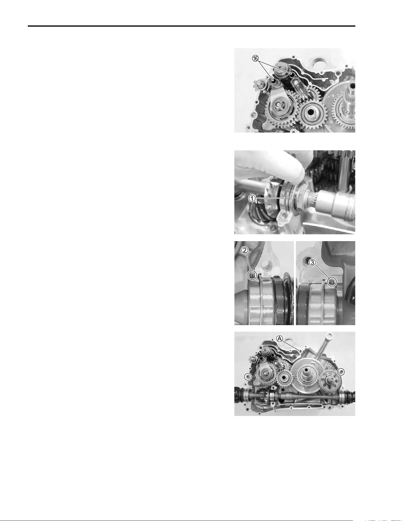
3-82 ENGINE
• Install the gearshifting fork shafts
F.
• After installing the gearshift forks and gears, turn the gearshift
cam and check to see that gears engage positively.
NOTE:
After the gearshifting fork shafts and gearshifting forks have
been fitted, confirm that gear change is normal while turning the
countershaft and driveshaft. If gear change is not obtained, it
means that assembly of gears or installation of gearshifting fork
is incorrect. If this is the case, disassemble and trace the mis-
take.
SECONDARY DRIVEN OUTPUT SHAFT
• When installing the secondary driven output shaft assembly,
be sure to install the C-ring
1 for the main bearing and place
the pin
2 to the groove for the front side bearing and the pin
3 to the groove for the rear side bearing.
CRANKCASE
• Wipe the crankcase mating surfaces (both surfaces) with a
cleaning solvent.
• Fit the dowel pins and O-ring
A onto the left half on the
crankcase.
• Apply engine oil to the conrod big end and the gears.
NOTE:
Coat the O-ring
A of crankcase with grease.
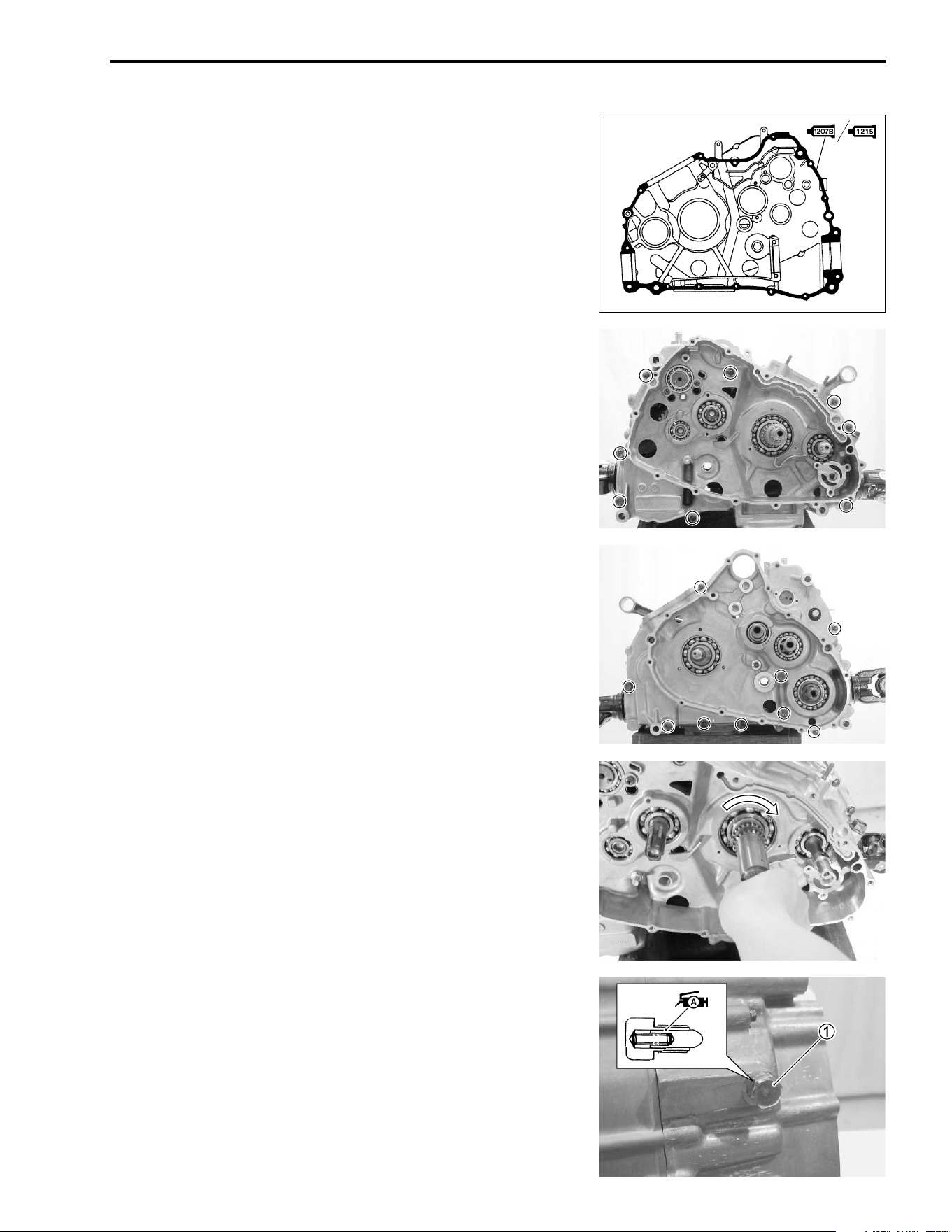
ENGINE 3-83
• Apply SUZUKI BOND “1207B/1215” to the mating surface of
the right crankcase.
+ 99104-31140: SUZUKI BOND “1207B” (USA)
, 99000-31110: SUZUKI BOND “1215” (Others)
• Assemble the crankcase within few minutes.
• Tighten the crankcase securing bolts for right side.
# Crankcase bolt (6 mm): 11 N·m (1.1 kgf-m, 8.0 lb-ft)
Crankcase bolt (8 mm): 22 N·m (2.2 kgf-m, 16.0 lb-ft)
• Tighten the crankcase securing bolts for left side.
# Crankcase bolt (6 mm): 11 N·m (1.1 kgf-m, 8.0 lb-ft)
Crankcase bolt (8 mm): 22 N·m (2.2 kgf-m, 16.0 lb-ft)
NOTE:
After the crankcase bolts have been tightened, check if the each
shaft rotates smoothly. If a large resistance is felt to rotation, try
to free the shafts by tapping them with a plastic mallet.
REVERSE CAM STOPPER BOLT
• Apply grease to the reverse cam stopper pin.
• Tighten the reverse cam stopper bolt
1.
# Stopper bolt: 23 N·m (2.3 kgf-m, 16.5 lb-ft)
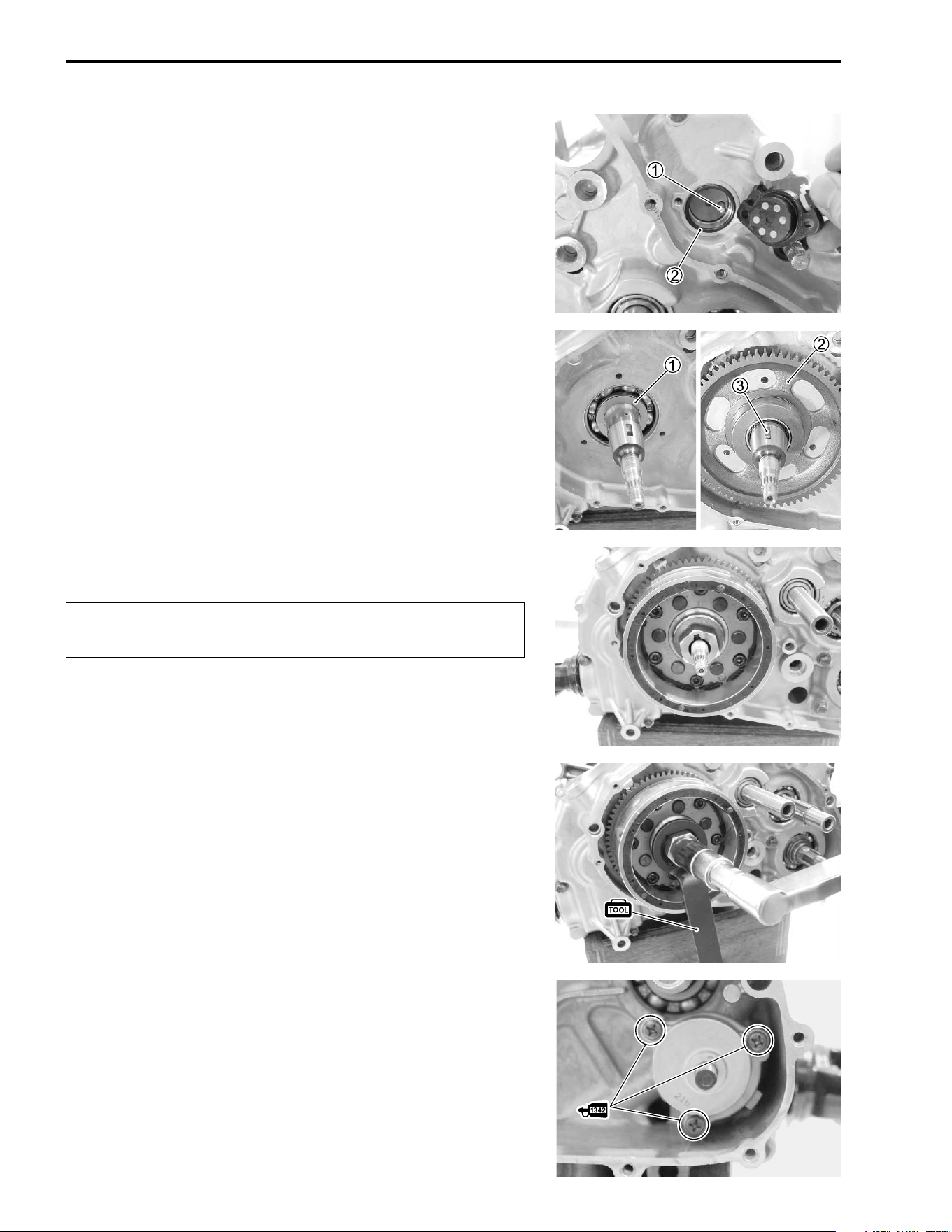
3-84 ENGINE
NEUTRAL SWITCH
• After positioning the spring and switch contact
1, install the
switch body with a new O-ring
2.
GENERATOR
• Install the washer
1.
• Install the starter driven gear
2.
• Install the key
3.
NOTE:
Degrease the tapered portion of the generator rotor assembly
and also the crankshaft. Use nonflammable cleaning solvent to
wipe off the oily or greasy matter to make these surfaces com-
pletely dry.
• Install the generator rotor assembly.
"
• Tighten the generator rotor nut to the specified torque with the
special tool.
# Generator rotor nut: 160 N·m (16.0 kgf-m, 115.5 lb-ft)
( 09930-44541: Rotor holder
OIL PUMP
• Apply engine oil to the sliding surfaces of the case, outer
rotor, inner rotor and shaft.
• Install the oil pump.
• Apply THREAD LOCK “1342” to the screws and tighten them.
& 99000-32050: THREAD LOCK “1342”
Make sure that the one way clutch on the crankshaft is
fitted into the generator rotor properly.
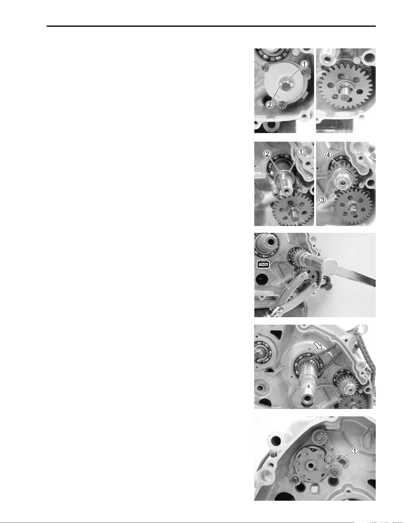
ENGINE 3-85
• Install the washer
1 and pin
2.
• Install the oil pump driven gear by installing the snap ring.
OIL PUMP DRIVE GEAR
• Install the spacer
1 and pin
2.
• Install the oil pump drive gear
3 and washer
4.
NOTE:
Flange side of the gear is positioned inside.
• Tighten the oil pump drive gear nut to the specified torque
with the special tool.
# Oil pump drive gear bolt: 80 N·m (8.0 kgf-m, 58.0 lb-ft)
( 09930-40113: Rotor holder
CAM CHAIN
• Install the cam chain.
GEARSHIFT
• Install the gearshift cam plate
1.
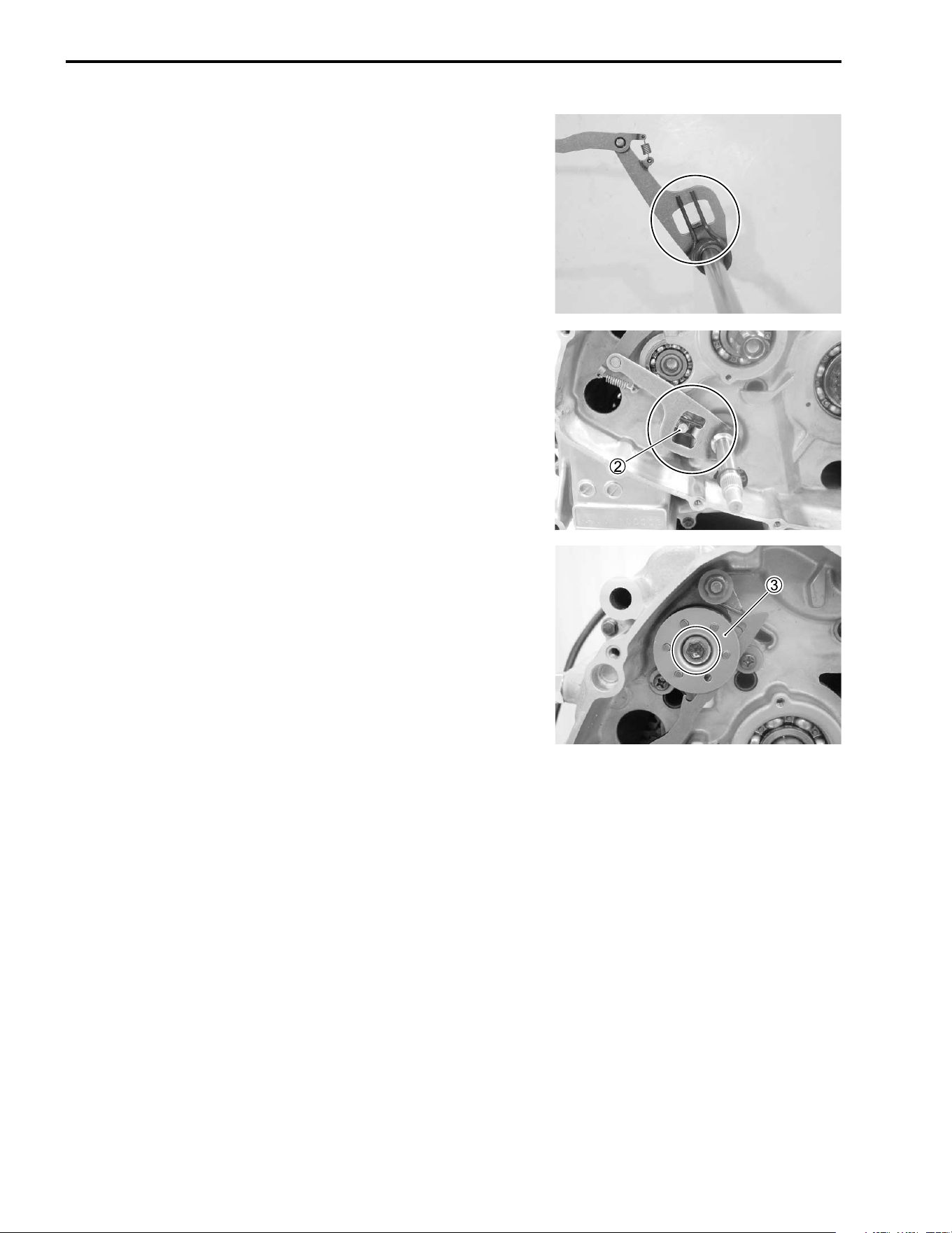
3-86 ENGINE
• Install the spring to the gearshift cam shaft properly.
• Install the gearshift cam shaft assembly while aligning the
spring ends with the stopper pin
2.
• Install the gearshift cam plate guide
3.
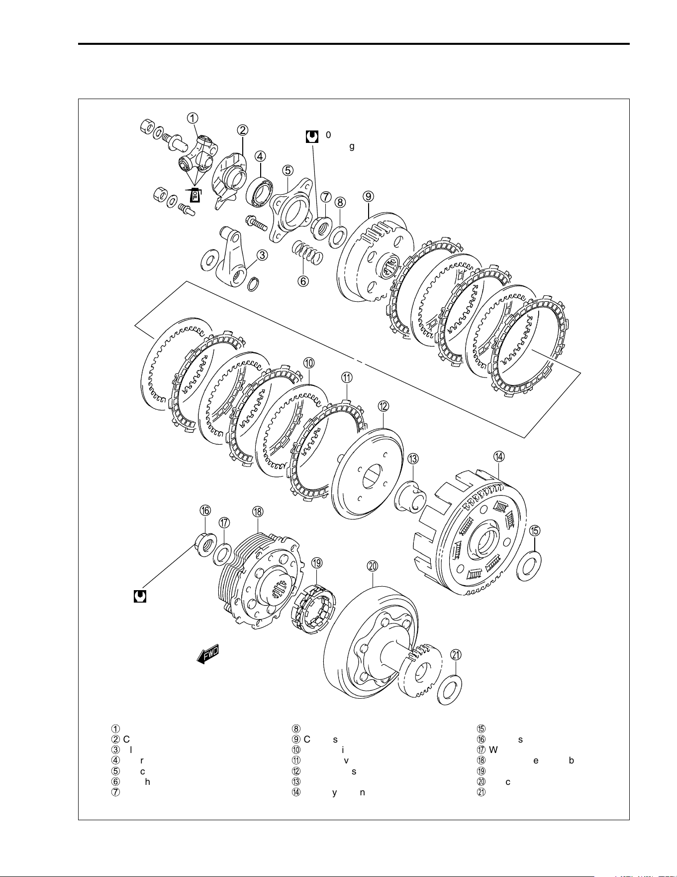
ENGINE 3-87
CLUTCH
1
Clutch release roller
2
Clutch release roller guide
3
Clutch release arm
4
Bearing
5
Clutch release plate
6
Clutch spring
7
Clutch sleeve hub nut
8
Washer
9
Clutch sleeve hub
0
Clutch driven plate
A
Clutch drive plate
B
Clutch pressure plate
C
Collar
D
Primary driven gear assembly
E
Washer
F
Clutch shoe nut
G
Washer
H
Clutch shoe assembly
I
One-way clutch
J
Clutch wheel
K
Washer
100 N·m
(10.0 kgf-m, 72.5 lb-ft)
130 N
.
m
(13.0 kgf
.
m,
94.0 lb-ft)
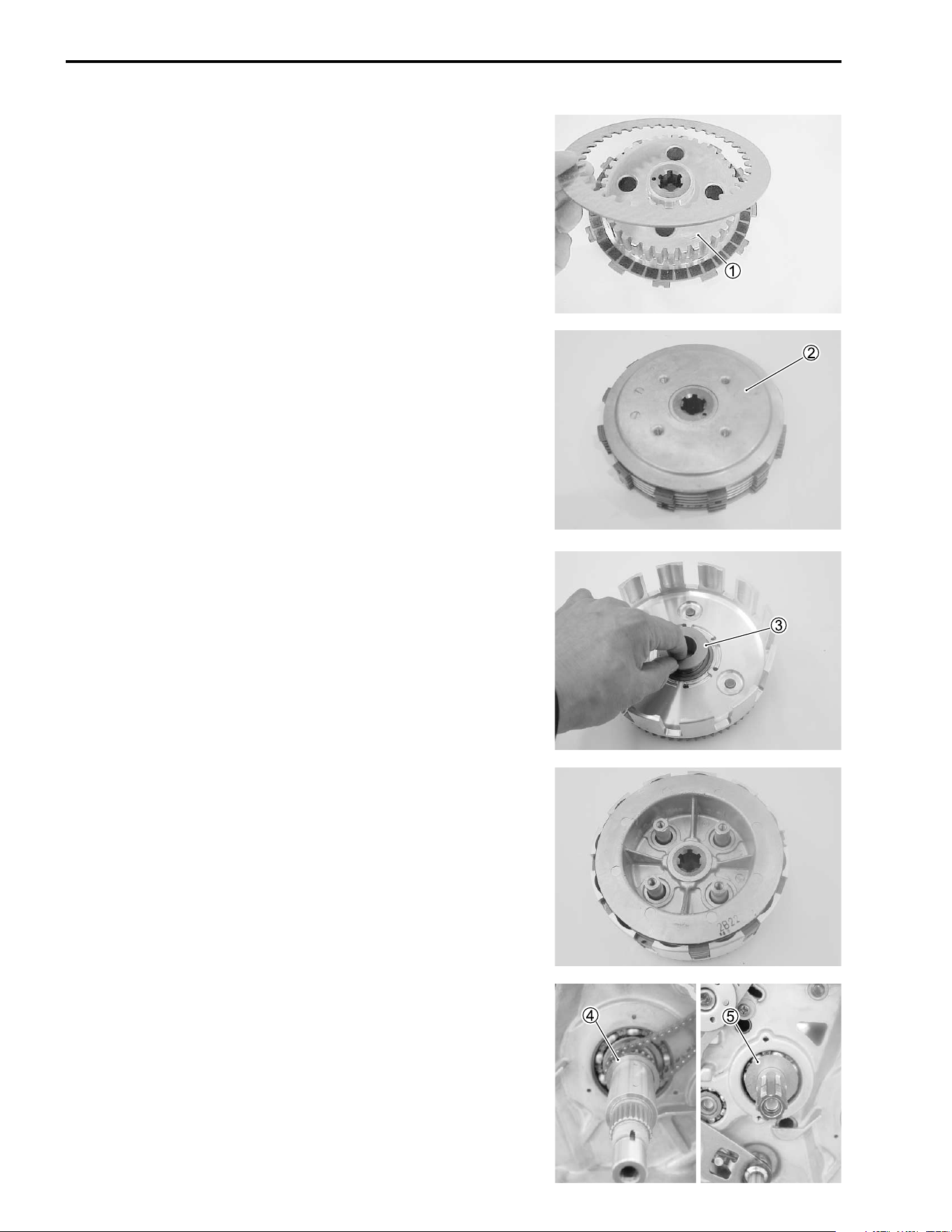
3-88 ENGINE
• Install the clutch drive plates and driven plates one by one
onto the clutch sleeve hub
1.
• Install the clutch pressure plate
2.
• Install the collar
3 onto the primary driven gear assembly.
• Install the clutch sleeve hub assembly into the primary driven
gear assembly.
• Install the washers,
4 and
5, on the crankshaft and the
countershaft.
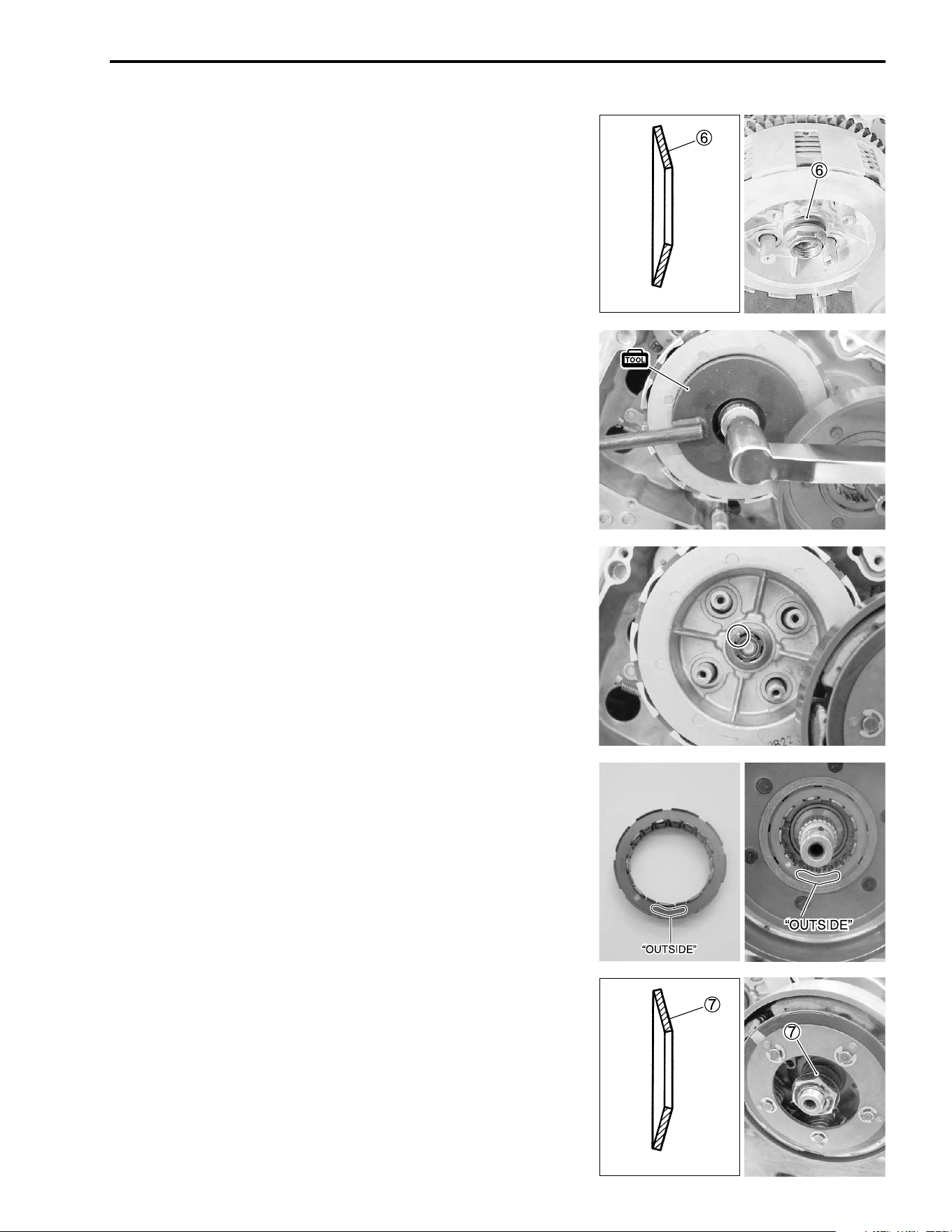
ENGINE 3-89
• Install the primary driven gear assembly together with the
clutch wheel.
• Install the washer
6 and clutch sleeve hub nut.
NOTE:
The convex side of the washer faces outside.
• Tighten the clutch sleeve hub nut to the specified torque with
the special tool.
# Clutch sleeve hub nut: 100 N·m (10.0 kgf-m, 72.5 lb-ft)
( 09920-53730: Clutch sleeve hub holder
• Stake the clutch sleeve hub nut with a center punch.
• Install the one-way clutch with facing the “OUTSIDE” mark
outside.
• Install the clutch shoe assembly.
• Install the washer
7 and clutch shoe nut.
NOTE:
The convex side of the washer faces outside.
INSIDE
Washer
OUTSIDE
INSIDE
Washer
OUTSIDE
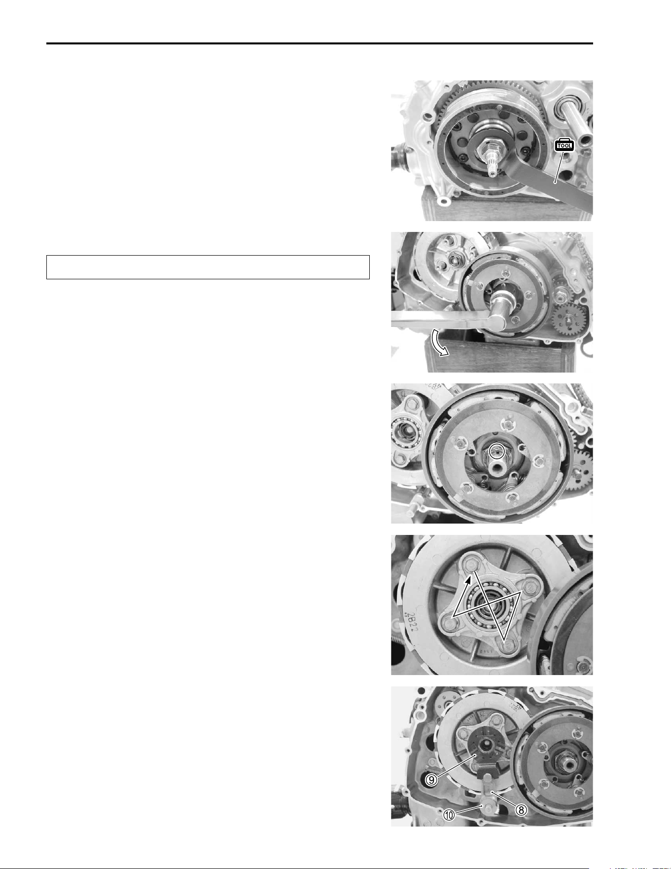
3-90 ENGINE
• Tighten the clutch shoe nut to the specified torque while hold-
ing the generator rotor with the special tool.
"
# Clutch shoe nut: 130 N·m (13.0 kgf-m, 94.0 lb-ft)
( 09930-44541: Generator rotor holder
• Stake to clutch shoe nut with a center punch.
• Install the clutch springs and clutch release plate.
• Tighten the clutch spring bolts diagonally.
• Install the clutch release arm
8, clutch release roller guide
9
and washer
0.
The clutch shoe nut has left-hand threads.
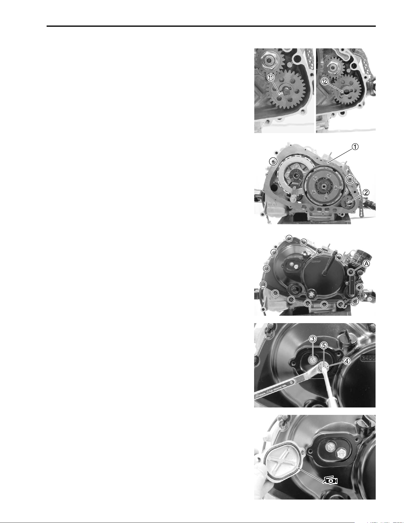
ENGINE 3-91
• Install the pin
A and water pump drive joint
B.
CLUTCH COVER
• Install the dowel pins and new gasket
1.
• Install the water pump drive joint
2.
• Install the clutch cover.
• Install the seal washer to the bolt
A.
• Loosen the locknuts
3 and
4.
• Rotate the adjusting screw
5 counterclockwise until it stops.
• Tighten the locknut
3.
• Rotate the adjusting screw
5 clockwise 1/4 – 2/4 turn.
• Tighten the locknut
4 by holding the adjuster screw
5.
# Locknut
3: 8 N·m (0.8 kgf-m, 5.7 lb-ft)
Locknut
4: 23 N·m (2.3 kgf-m, 16.5 lb-ft)
• Apply SUZUKI SUPER GREASE “A” to the O-ring and install
the clutch adjuster cap.
' 99000-25030: SUZUKI SUPER GREASE “A” (USA)
99000-25010: SUZUKI SUPER GREASE “A” (Others)
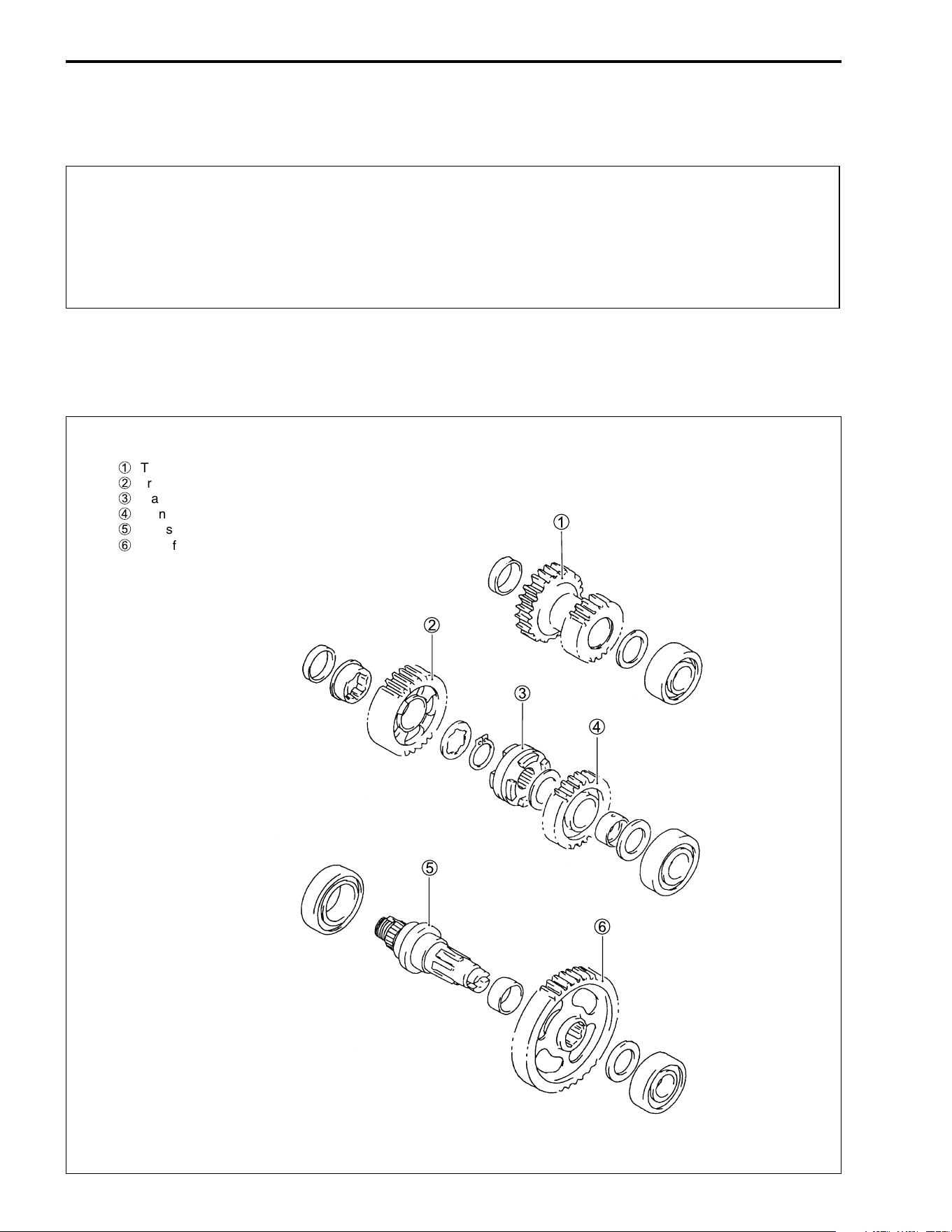
3-92 ENGINE
TRANSFER
"
NOTE:
In reassembling the transfer, attention must be given to the locations and positions of washers and circlips.
The cross sectional view given here will serve as a reference for correctly mounting the gears, washers and
snap rings.
* Never reuse a snap ring. After a snap ring has been removed from a shaft, the removed snap
ring should be discarded and a new snap ring must be installed.
* When installing a new snap ring, care must taken not to expand the end gap larger than
required to slip the snap ring over the shaft.
* After installing a snap ring, always ensure that it is completely seated in its groove and
securely fitted.
1
Transfer idle gear
2
Transfer NO. 1 gear
3
Transfer selection
4
Transfer NO. 2 gear
5
Transfer output shaft
6
Transfer driven gear
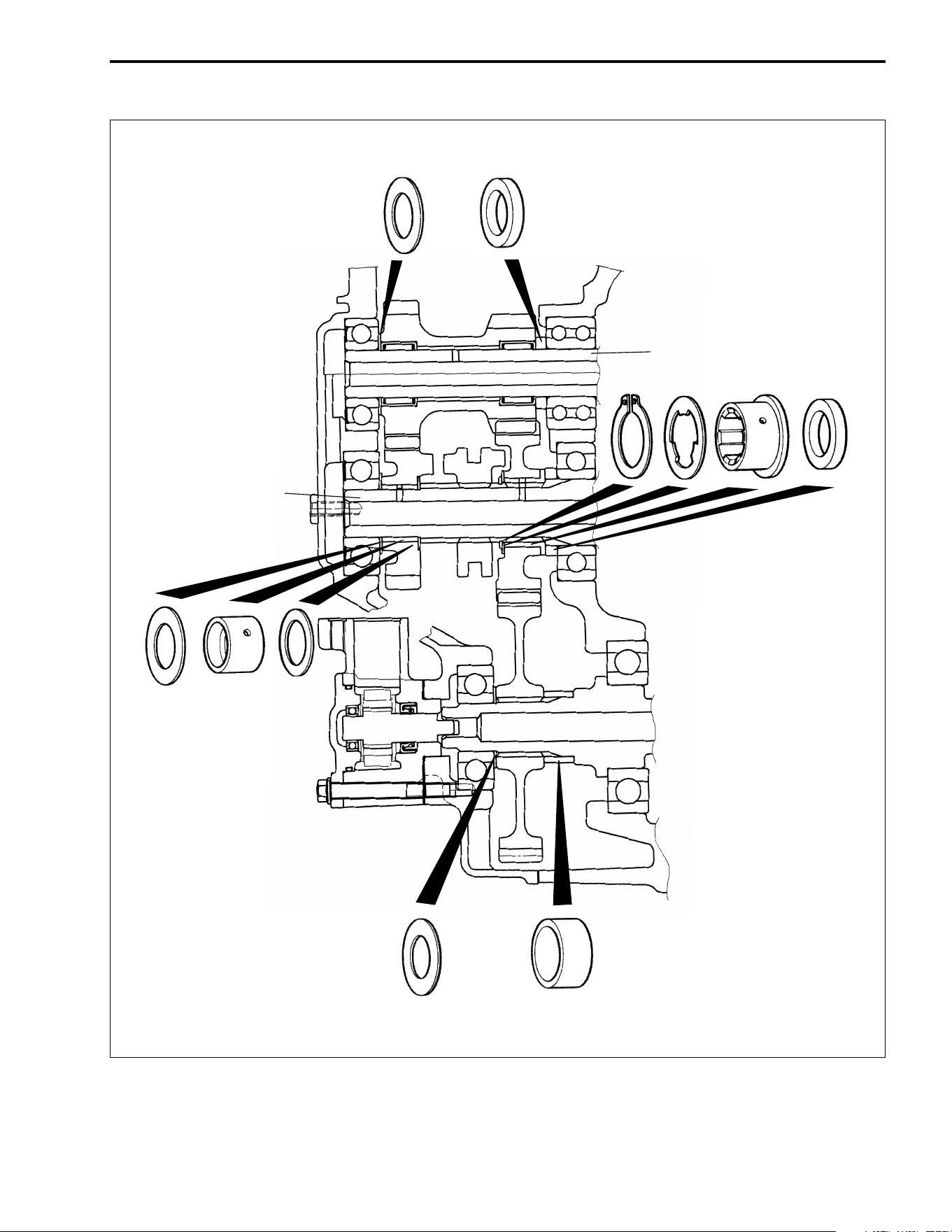
ENGINE 3-93
Countershaft
Driveshaft
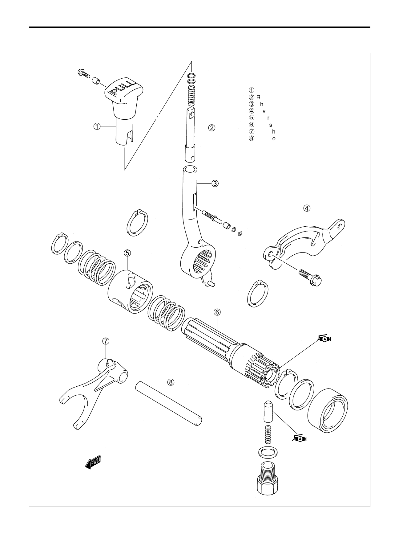
3-94 ENGINE
1
Knob
2
Rod
3
Shift lever assy
4
Lever stopper plate
5
Gearshift cam
6
Gearshift shaft
7
Gearshift fork
8
Gear fork shaft
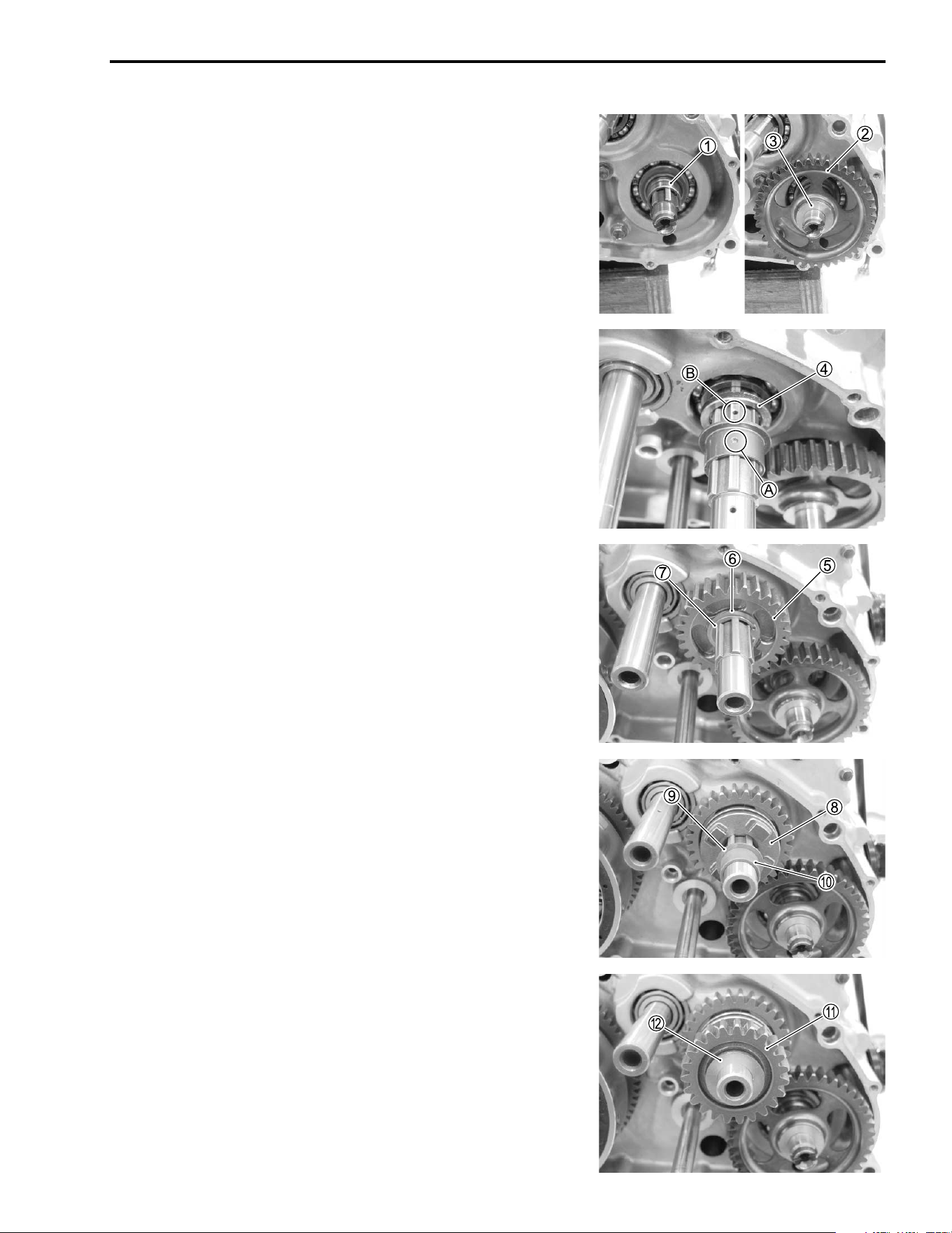
ENGINE 3-95
TRANSFER
• Install the spacer
1.
• Install the output gear
2 and washer
3.
• Install the spacer
4.
• Install the bushing by aligning the hole
A with the hole
B on
the shaft.
• Install the transfer No. 1 gear
5.
• Install the washer
6 and snap ring
7.
• Install the transfer selection dog
8.
• Install the washer
9 and spacer
0.
• Install the transfer No. 2 gear
A.
• Install the washer
B.
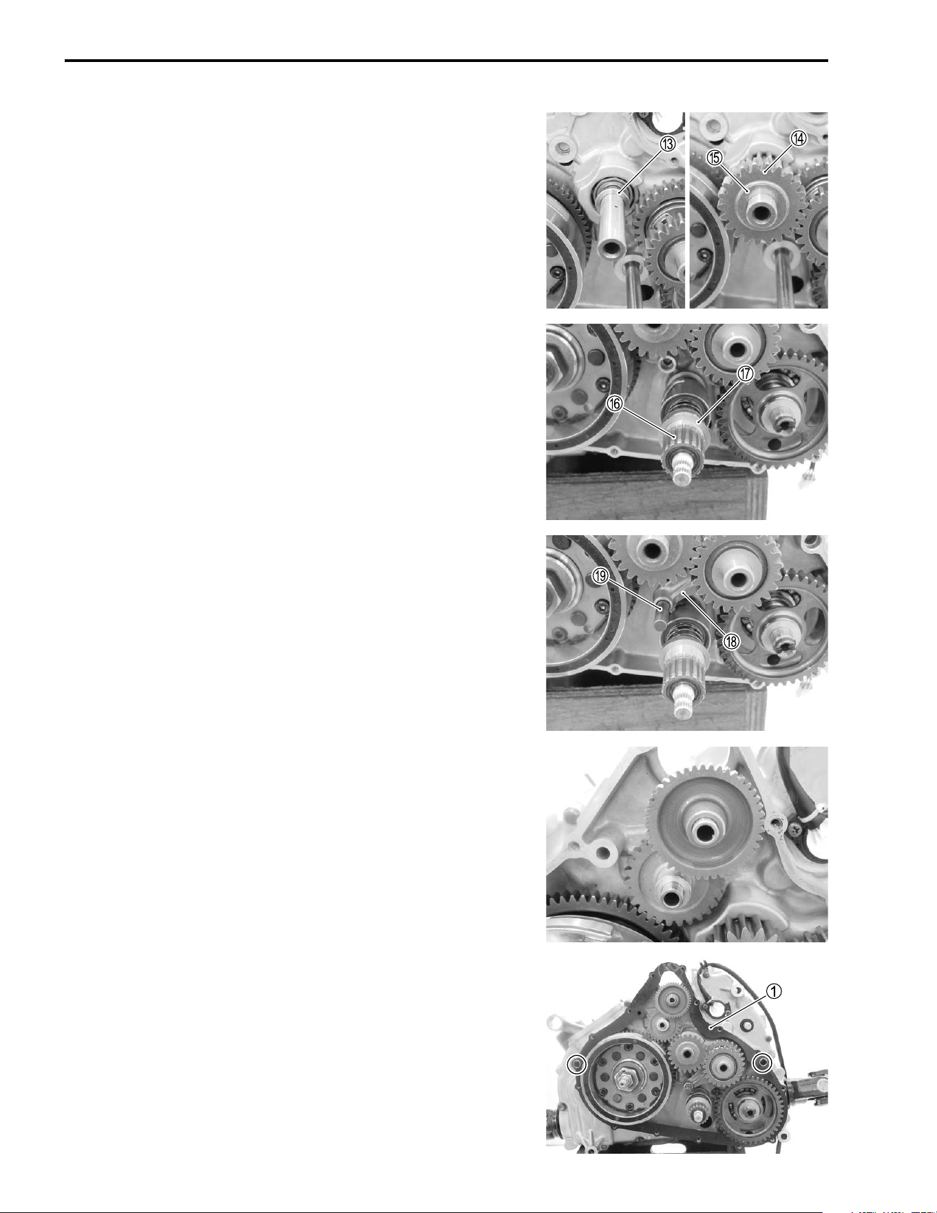
3-96 ENGINE
• Install the spacer
C.
• Install the transfer idle gear
D and washer
E.
• Install the transfer gearshift shaft
F and washer
G.
• Install the transfer gearshift fork
H and shaft
I.
STARTER DRIVEN GEAR/IDLE GEAR
• Install the starter driven gear and idle gear.
• Install the dowel pins and new gasket
1.
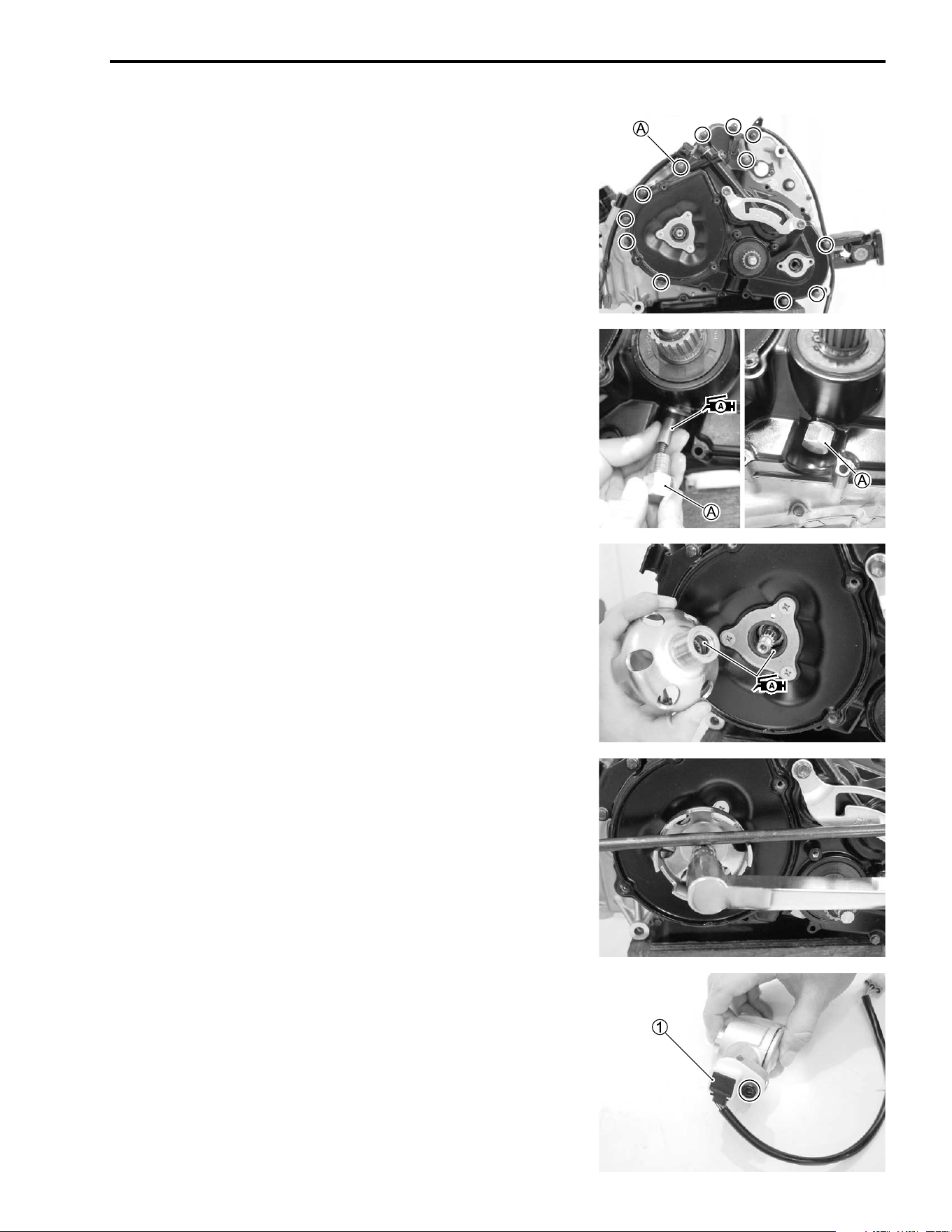
ENGINE 3-97
• Tighten the generator cover bolt.
• Install the seal washer to the bolt
A.
• Apply SUZUKI SUPER GREASE “A” to the gearshift cam
stopper.
• Install the gearshift cam stopper bolt
A.
• Tighten the bolt
A.
' 99000-25030: SUZUKI SUPER GREASE “A” (USA)
99000-25010: SUZUKI SUPER GREASE “A” (Others)
# Transfer shift cam stopper bolt:
23 N·m (2.3 kgf-m, 16.5 lb-ft)
STARTER CUP
• Apply SUZUKI SUPER GREASE “A” to the O-ring and lip of
the oil seal.
• Install the starter cup.
' 99000-25030: SUZUKI SUPER GREASE “A” (USA)
99000-25010: SUZUKI SUPER GREASE “A” (Others)
• Tighten the starter cup nut by using a suitable bar.
SPEEDOMETER GEARBOX
• Remove the speed sensor
1.
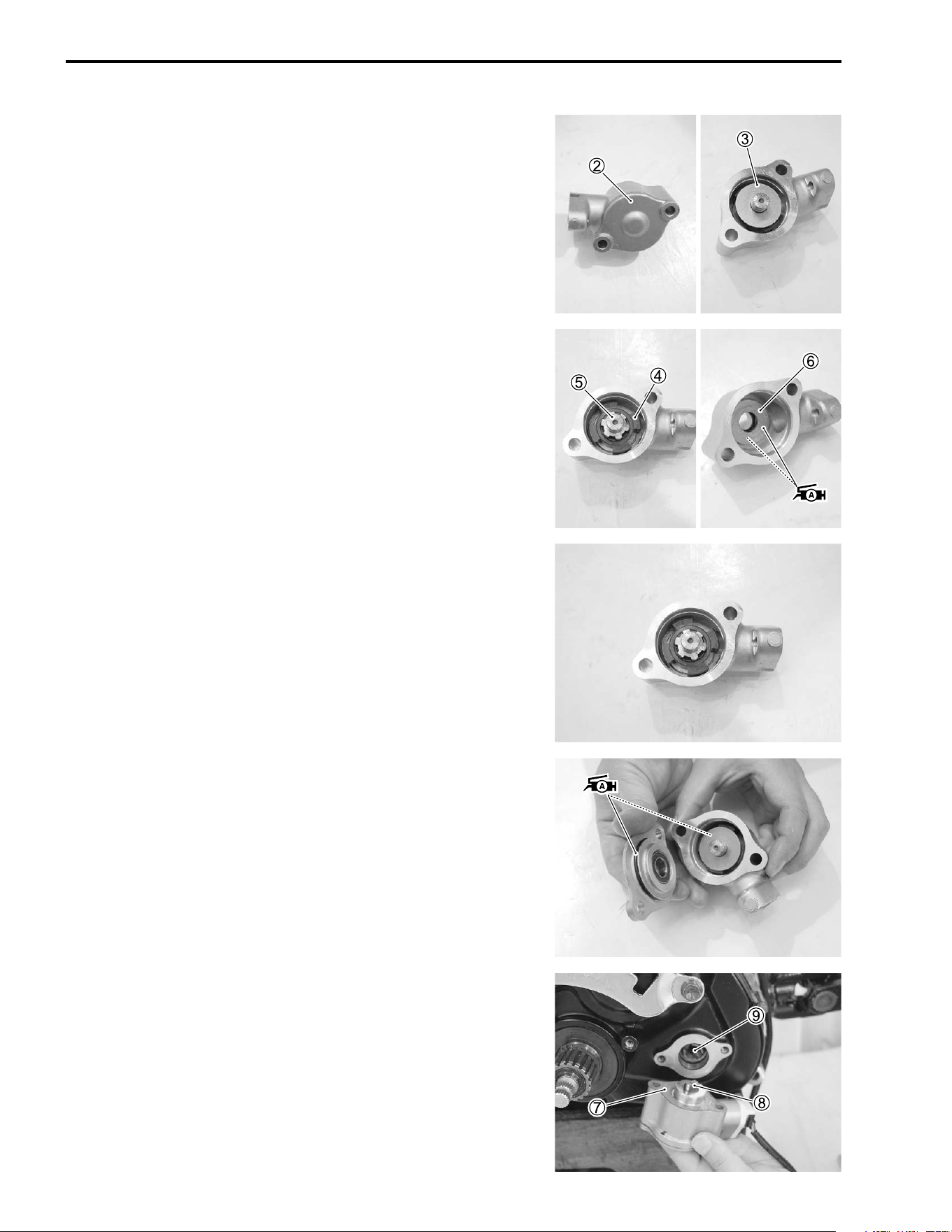
3-98 ENGINE
• Remove the gearbox cap
2 and washer
3.
• Remove the speed sensor rotor
4, shaft
5 and washer
6.
• Apply SUZUKI SUPER GREASE “A” to the washer.
' 99000-25030: SUZUKI SUPER GREASE “A” (USA)
99000-25010: SUZUKI SUPER GREASE “A” (Others)
• Install the washer, speed sensor shaft and rotor.
• Apply SUZUKI SUPER GREASE “A” to the O-ring and
washer.
• Install the washer and cap.
' 99000-25030: SUZUKI SUPER GREASE “A” (USA)
99000-25010: SUZUKI SUPER GREASE “A” (Others)
• Fit a new gasket
7 and install the gearbox.
• Align the protrusion
8 of the gearbox with the groove
9 of
the transfer output shaft.
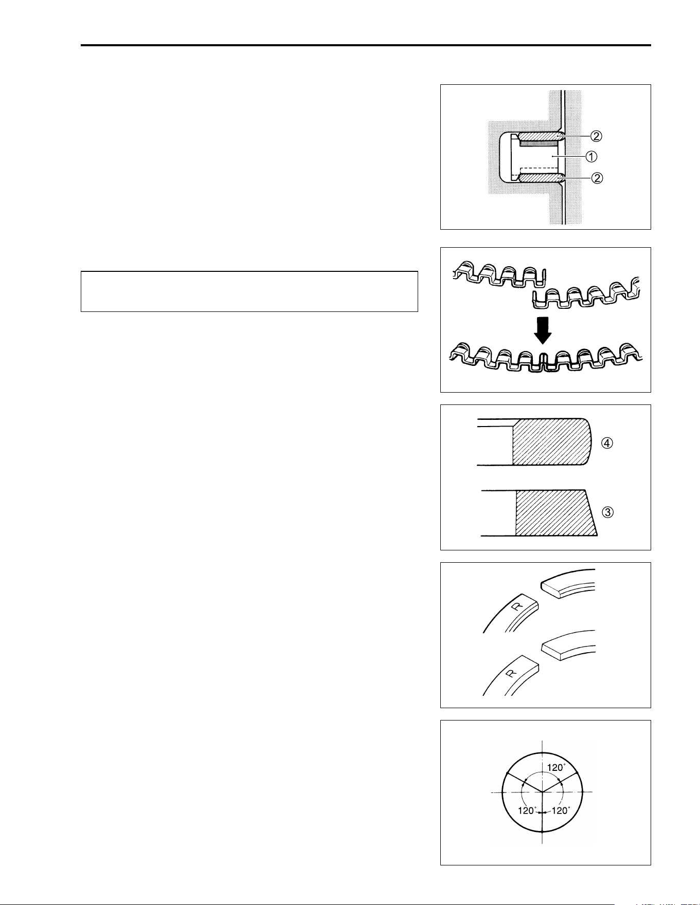
ENGINE 3-99
ENGINE TOP SIDE
PISTON
• Install the piston rings in the order of oil ring, 2nd ring and 1st
ring.
• The first member to go into the oil ring groove is a spacer
1.
After placing the spacer, fit the two side rails
2.
NOTE:
Side designations, top and bottom, are not applied to the spacer
and side rails: Those can be positioned each either way.
"
• Install the 2nd ring
3 and the 1st ring
4.
NOTE:
1st ring and 2nd ring differ in shape.
• 1st ring and 2nd ring have letter “R” marked on the side. Be
sure to bring the marked side to the top when fitting them to
the piston.
• Position the gaps of the three rings as shown. Before inserting
the piston into the cylinder, check that the gaps are so
located.
When installing the spacer, be careful not to allow its
two ends to overlap in the groove.
INCORRECT
CORRECT
1st ring
2nd ring
EX
IN
• 2nd ring
• Lower side
rail
• Upper side
rail
• 1st ring
• Spacer
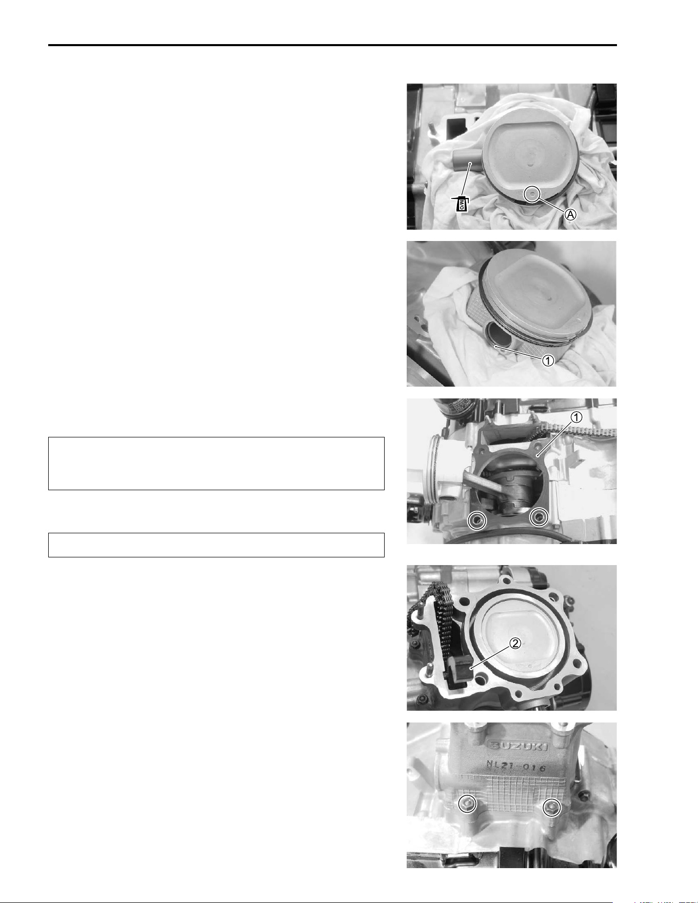
3-100 ENGINE
• Apply a light coat of molybdnum oil solution to the piston pin.
* MOLYBDNUM OIL SOLUTION
• Install the piston and piston pin.
NOTE:
When installing the piston, the dent
A on the piston head is
located to the exhaust side.
• Place a cloth beneath the piston, install the circlip
1.
CYLINDER
"
• Fit the dowel pins and the new gasket
1.
"
• Install the cam chain guide
2.
NOTE:
There is a holder for the bottom end of the cam chain guide cast
in the crankcase. Be sure that the guide
2 is inserted properly
or binding of the cam chain and guide may result.
• Hold each piston ring with properly position, insert the piston
into the cylinder.
• Tighten the cylinder base nuts temporarily.
When turning the crankshaft, pull the cam chain
upward, or the chain will be caught between the crank-
case and the cam drive sprocket.
Use a new gasket to prevent gas leakage.
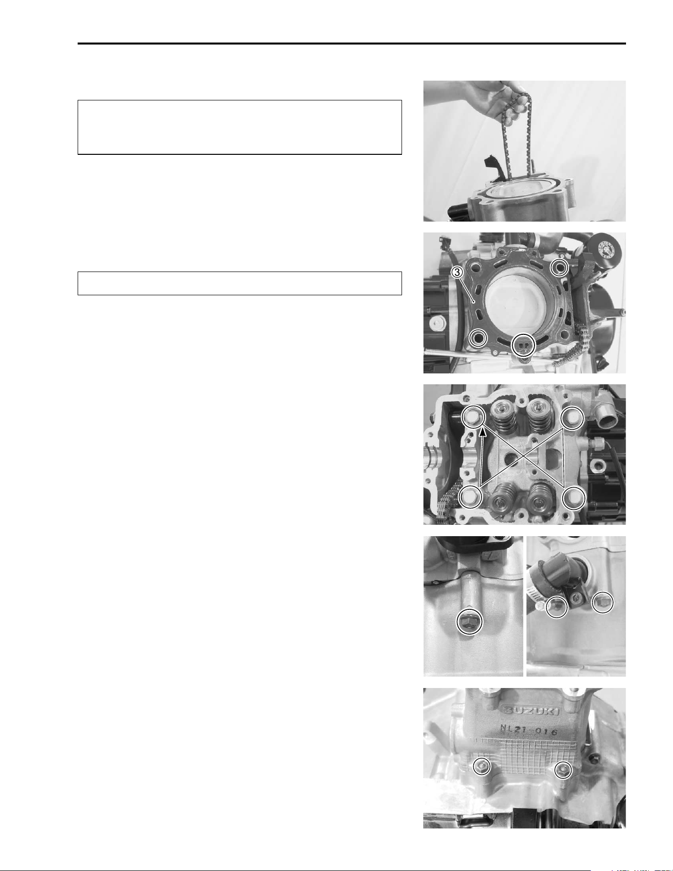
ENGINE 3-101
"
• Fit the dowel pins and new cylinder head gasket
3.
"
NOTE:
Attach the gasket so that the side marked “UP” faces upward.
CYLINDER HEAD
• Install the cylinder head and tighten the cylinder head bolts
diagonally to the specified torque.
# Cylinder head bolt
Initial: 25 N·m (2.5 kgf-m, 18.0 lb-ft)
Final : 38 N·m (3.8 kgf-m, 27.5 lb-ft)
• Tighten the cylinder head nuts to the specified torque.
# Cylinder head nut
8 mm: Initial: 10 N·m (1.0 kgf-m, 7.0 lb-ft)
Final: 25 N·m (2.5 kgf-m, 18.0 lb-ft)
6 mm: 10 N·m (1.0 kgf-m, 7.0 lb-ft)
• Tighten the cylinder base nuts to the specified torque.
# Cylinder base nut: 10 N·m (1.0 kgf-m, 7.0 lb-ft)
When installing the cylinder and cylinder head, pull
the cam chain upward, or the chain will be caught
between the crankcase and cam drive sprocket.
Use a new gasket to prevent gas leakage.
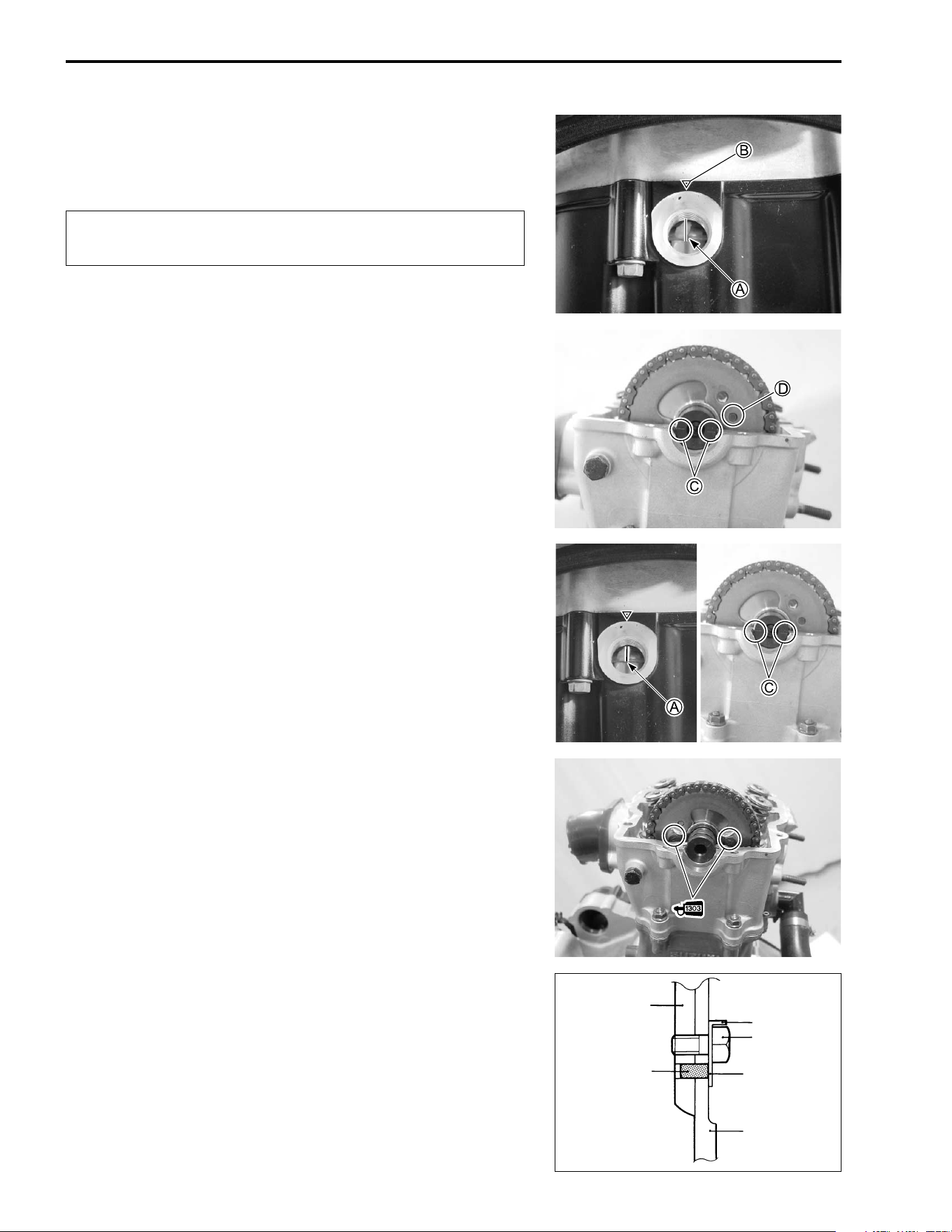
3-102 ENGINE
CAMSHAFT
• Align the line
A on the generator rotor with the index mark
B
on the crankcase.
"
• Align the marks
A on the camshaft so that they are parallel
with the surface of the cylinder head.
NOTE:
Do not rotate the generator while doing this. When the sprocket
is not positioned correctly, turn the sprocket.
• Engage the locating pin
D on the camshaft with the hole as
shown.
• Recheck the position of the line
A and marks
C.
• Install the lock washer so that it is covering the locating pin.
• Apply THREAD LOCK SUPER “1303” to the bolts and tighten
them to the specified torque.
# Camshaft sprocket bolt: 15 N·m (1.5 kgf-m, 11.0 lb-ft)
$ 99000-32030: THREAD LOCK SUPER “1303”
• Bend up the washer tongue positively to lock the bolts.
Pull the cam chain upward, or the chain will be caught
between crankcase and cam drive sprocket.
Camshaft
Pin
Bend up
Bolt
Washer
Sprocket
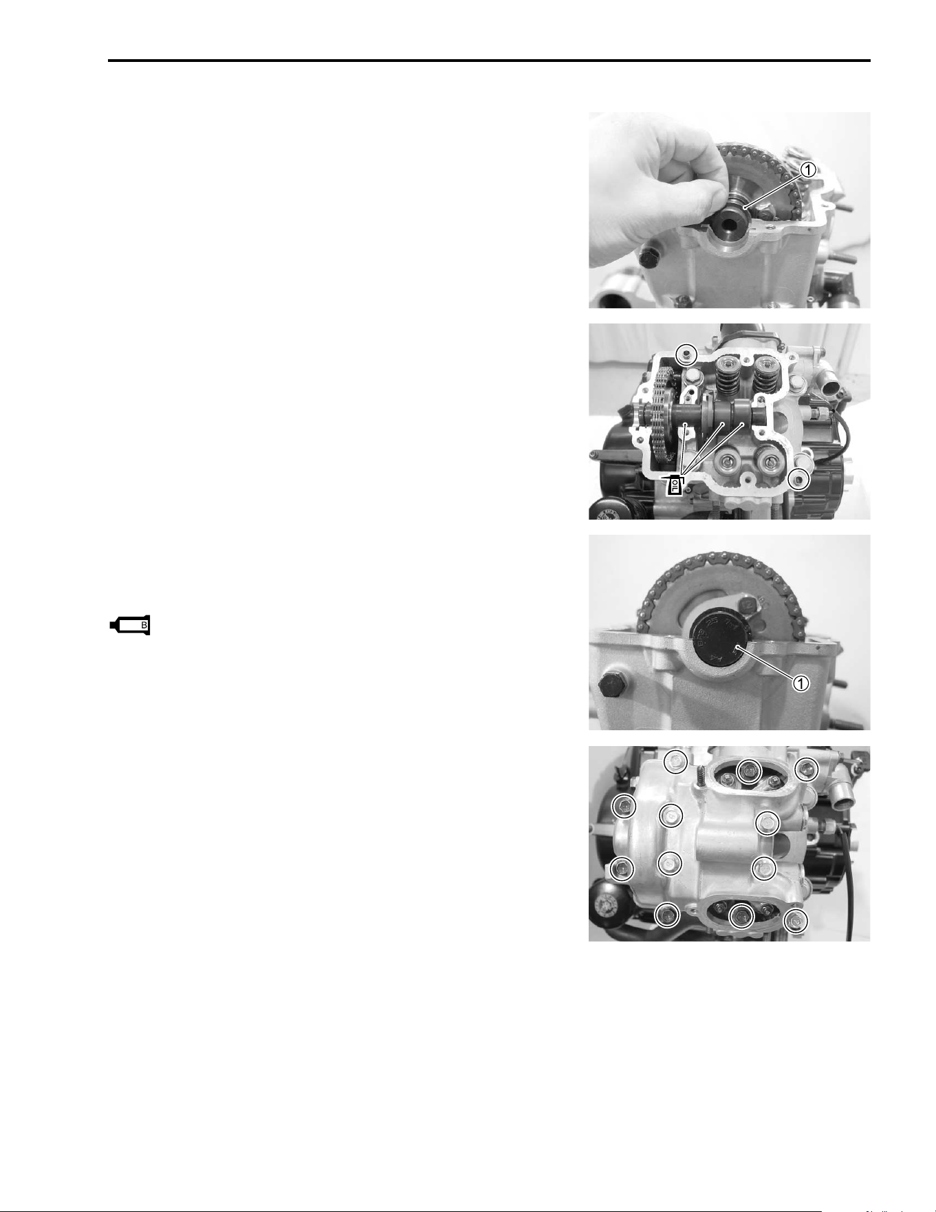
ENGINE 3-103
• Install the C-ring
1.
CYLINDER HEAD COVER
• Clean the mating surface of the cylinder head and head cover
before matching.
• Install the dowel pins to the cylinder head.
• Apply engine oil to the cam face and camshaft journal.
• Apply SUZUKI BOND “1216B” to the mating surface of the
cylinder head cover. (!3-104)
• Fit the camshaft end cap
1.
99000-31230: SUZUKI BOND “1216B”
• Lightly tighten the cylinder head cover bolts diagonally, and
then if everything is satisfactory, tighten securely with a
torque wrench to the specified torque.
# Cylinder head cover bolt: 10 N·m (1.0 kgf-m, 7.0 lb-ft)
NOTE:
When tightening the cylinder head cover bolts, the piston must
be at top dead center on the compression stroke.
1216
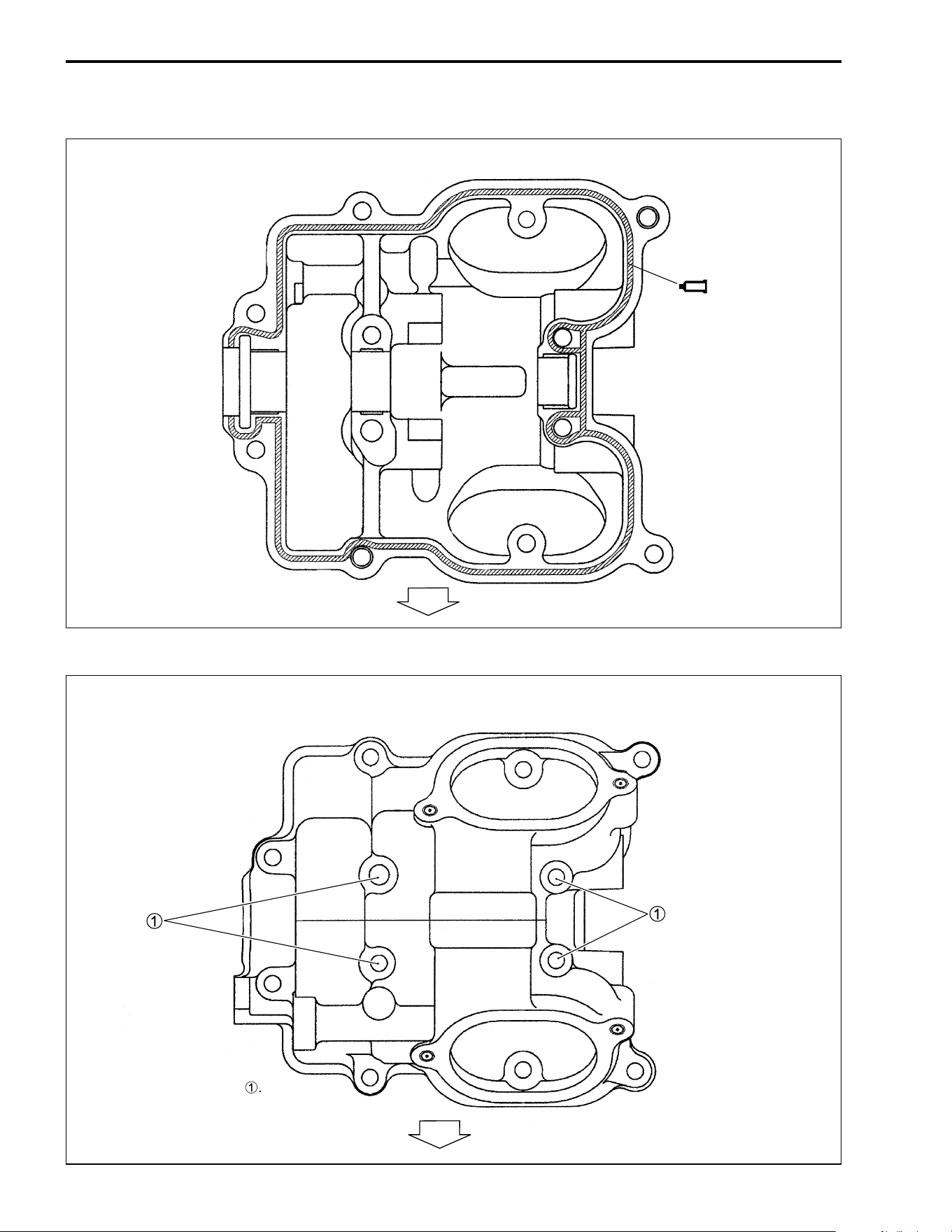
3-104 ENGINE
LIQUID GASKET APPLYING PLACE
LOCATION OF CYLINDER HEAD COVER BOLT
1216B
FWD
NOTE:
* Fit the gasket to the bolt
1
.
FWD
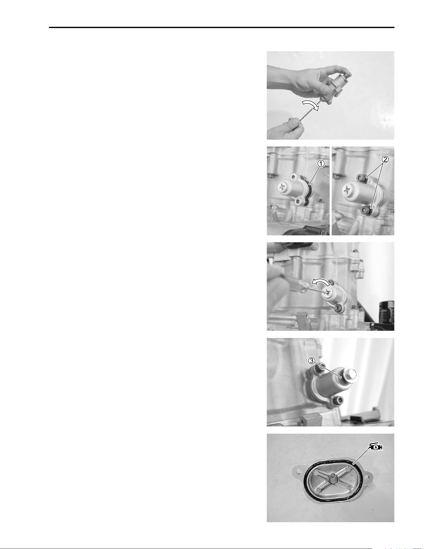
ENGINE 3-105
CAM CHAIN TENSION ADJUSTER
• Insert the
- screwdriver into the slotted end of the cam chain
tension adjuster, then turn it clockwise to lock the spring ten-
sion.
• Install the new gasket
1 and cam chain tension adjuster.
• Install the new gaskets
2 and tighten the bolts to the speci-
fied torque.
# Cam chain tension adjuster mounting bolt:
10 N·m (1.0 kgf-m, 7.0 lb-ft)
• After installing the cam chain tension adjuster, turn a
-
screwdriver counterclockwise.
NOTE:
As the slotted end turns, the tension rod is advanced under
spring force and pushes the cam chain tension adjuster against
the cam chain.
• Install the new gasket
3 and tighten the spring holder bolt to
the specified torque.
# Spring holder bolt: 8 N·m (0.8 kgf-m, 5.7 lb-ft)
• Adjust the valve clearance. (!2-5)
• Apply grease to the new O-rings and install the valve inspec-
tion caps.
' 99000-25030: SUZUKI SUPER GREASE “A” (USA)
99000-25010: SUZUKI SUPER GREASE “A” (Others)
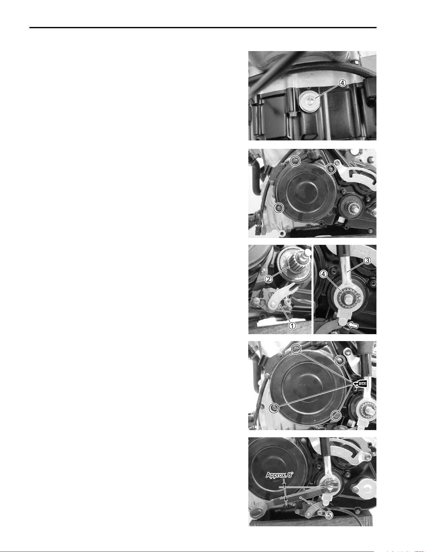
3-106 ENGINE
• Tighten valve timing inspection plug
4 to the specified
torque.
# Valve timing inspection plug:
23 N·m (2.3 kgf-m, 16.5 lb-ft)
RECOIL STARTER
• Temporarily install the recoil starter.
GEARSHIFT LEVER
• Install the shift lever position switch
1 and snap ring
2.
• Install the shift lever assembly
3 with the pin engaged with
the switch
1.
• Install the snap ring
4.
• Install the recoil starter.
• Apply a small quantity of THREAD LOCK “1342” to the bolts.
& 99000-32050: THREAD LOCK “1342”
• Install the gearshift lever
5.
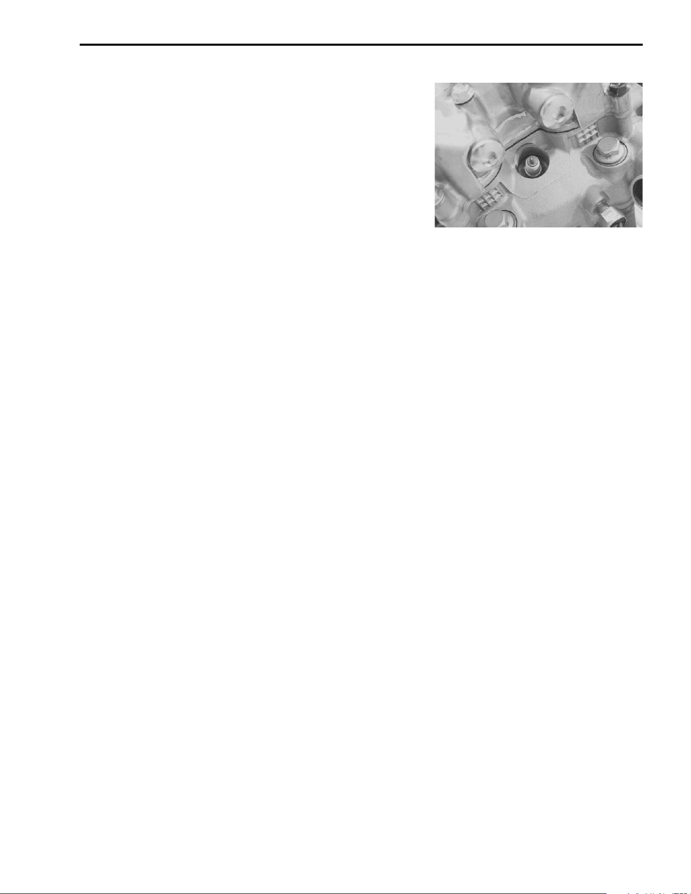
ENGINE 3-107
• Install the spark plug.
( 09930-10121: Spark plug wrench set

2
4
6
DRIVE TRAIN 4-1
CONTENTS
DRIVE TRAIN
DRIVE TRAIN .......................................................................................4- 2
FRONT DRIVING SYSTEM ..........................................................4- 2
FRONT DRIVE (DIFFERENTIAL) REMOVAL .............................4- 3
FRONT DRIVE (DIFFERENTIAL) DISASSEMBLY .....................4- 3
FRONT DRIVE (DIFFERENTIAL) INSPECTION .........................4- 7
FRONT DRIVE (DIFFERENTIAL) REASSEMBLY ......................4-10
FRONT DRIVE (DIFFERENTIAL) INSTALLATION .....................4-16
SHIM ADJUSTMENT ...................................................................4-17
REASSEMBLY INFORMATION ..................................................4-20
REAR DRIVING SYSTEM ....................................................................4-21
REAR DRIVE REMOVAL .............................................................4-22
REAR DRIVE DISASSEMBLY .....................................................4-23
REAR DRIVE INSPECTION .........................................................4-28
REAR DRIVE REASSEMBLY ......................................................4-31
REAR DRIVE INSTALLATION ....................................................4-36
SHIM ADJUSTMENT ...................................................................4-38
REASSEMBLY INFORMATION ..................................................4-41
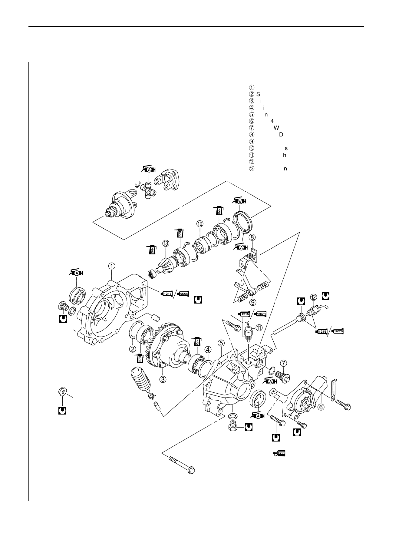
4-2 DRIVE TRAIN
DRIVE TRAIN
FRONT DRIVING SYSTEM
35 N
.
m
(3.5 kgf-m,
25.5 lb-ft)
32 N
.
m
(3.2 kgf-m,
23.0 lb-ft)
23 N
.
m (2.3 kgf-m, 16.5 lb-ft)
12 N
.
m (1.2 kgf-m,
8.5 lb-ft)
17 N
.
m
(1.7 kgf-m,
12.5 lb-ft)
17 N
.
m
(1.7 kgf-m,
12.5 lb-ft)
45 N
.
m
(4.5 kgf-m, 32.5 lb-ft)
1
Front drive (differential) gear case
2
Shim(s), RH
3
Differential assy
4
Shim(s), LH
5
Front drive (differential) gear case cover
6
2WD/4WD shifting motor
7
2WD/4WD shifting pinion
8
2WD/4WD shifting rack
9
2WD/4WD shifting fork
0
2WD/4WD shifting sleeve
A
4WD switch
B
2WD switch
C
Bevel pinion gear
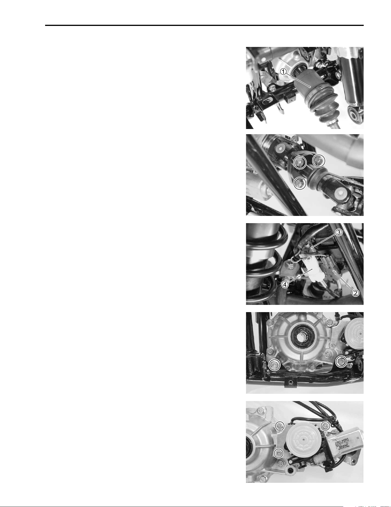
DRIVE TRAIN 4-3
FRONT DRIVE (DIFFERENTIAL) REMOVAL
• Remove the front fender and front wheels. (!7-6 and 7-11)
• Drain the differential gear oil. (!2-11)
• Remove the front suspension. (!7-33)
• Hold the inboard joint
1 of the drive shaft and tug the drive
shaft horizontally.
NOTE:
If it is difficult to remove the drive shaft from the differential case,
use the special tool.
• Remove the front propeller shaft flange coupling bolts.
• Disconnect the following lead wire couples.
2 2WD lead wire coupler
3 2WD/4WD motor lead wire coupler
4 4WD lead wire coupler
• Remove the front drive (differential) gear case mounting bolts.
• Remove the front drive (differential) assembly out of the
frame.
FRONT DRIVE (DIFFERENTIAL)
DISASSEMBLY
2WD/4WD SHIFTING MOTOR
• Remove the 2WD/4WD shifting motor assembly.
MOTOR INSPECTION !8-23.
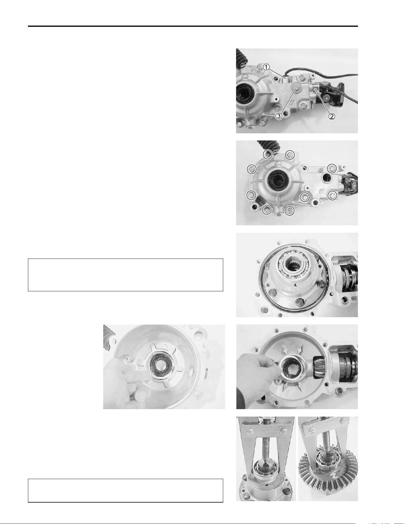
4-4 DRIVE TRAIN
2WD/4WD SHIFTING PINION AND SWITCH
• Remove the 4WD switch
1 and 2WD switch
2.
• Remove the 2WD/4WD shifting pinion
3.
2WD/4WD SWITCHES INSPECTION !8-24.
FRONT DRIVE (DIFFERENTIAL) GEAR CASE
• Remove the front drive (differential) gear case cover bolts in a
crisscross pattern.
• Remove the differential assembly and shims.
"
• Remove the bearings from the differential assembly with a
commercially available bearing puller.
NOTE:
If there is no abnormal condition, the bearing removal is not nec-
essary.
"
* Do not attempt to disassemble the differential
assembly.
* The differential is available only as an assembly.
The removed bearing must be replaced with a new
one.
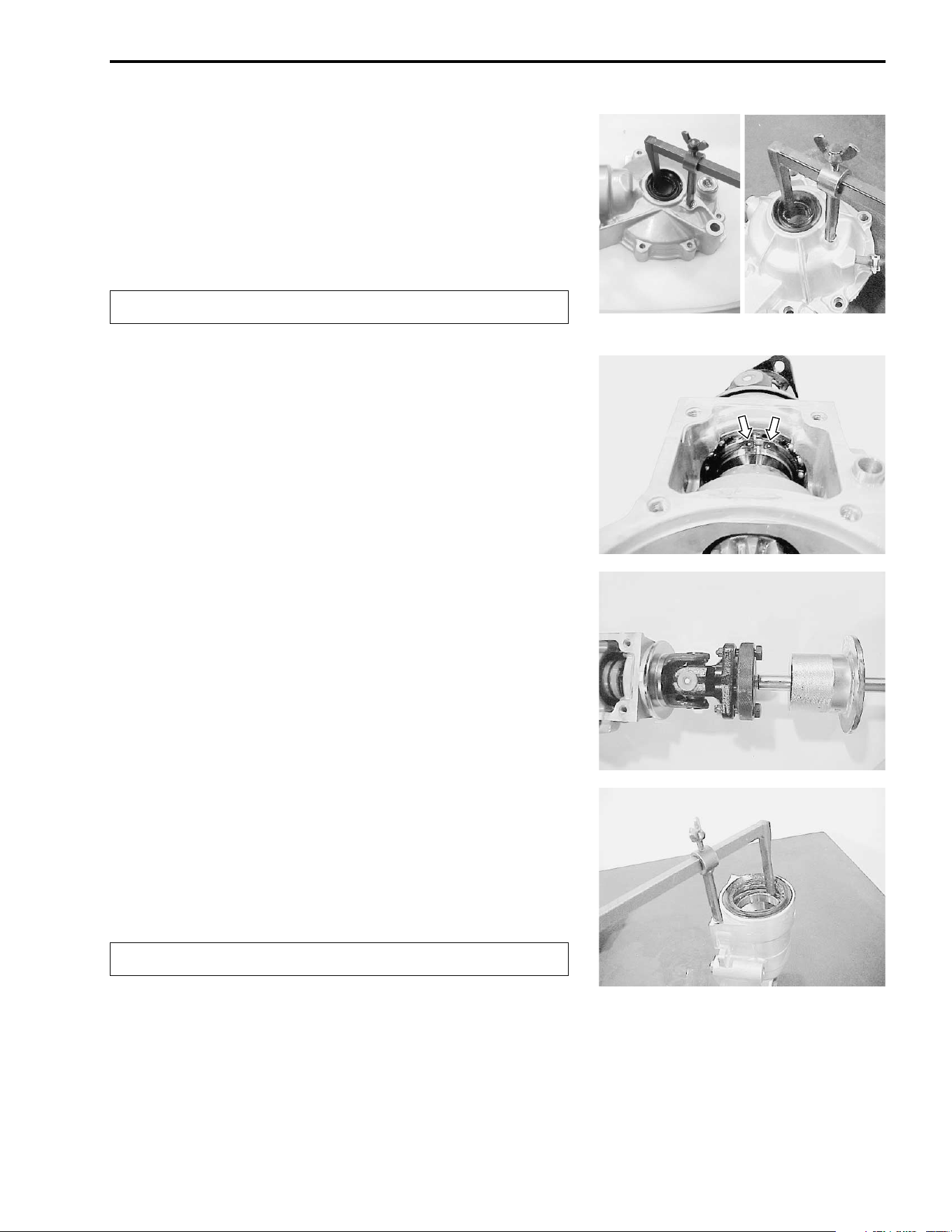
DRIVE TRAIN 4-5
• Remove the oil seals out of the gear case and its cover with
the special tool.
# 09913-50121: Oil seal remover
NOTE:
If there is no abnormal condition, the oil seal removal is not nec-
essary.
"
SHIFTING SLEEVE/UNIVERSAL JOINT YOKE
• Remove the snap ring out of its groove and slide it towards
the shifting sleeve.
• Remove the universal joint yoke assembly with the special
tool.
# 09930-30190: Rotor remover attachment
09930-30104: Sliding shaft
• Remove the oil seal out of the gear case with the special tool.
# 09913-50121: Oil seal remover
NOTE:
If there is no abnormal condition, the oil seal removal is not nec-
essary.
"
The removed oil seal must be replaced with a new one.
The removed oil seal must be replaced with a new one.
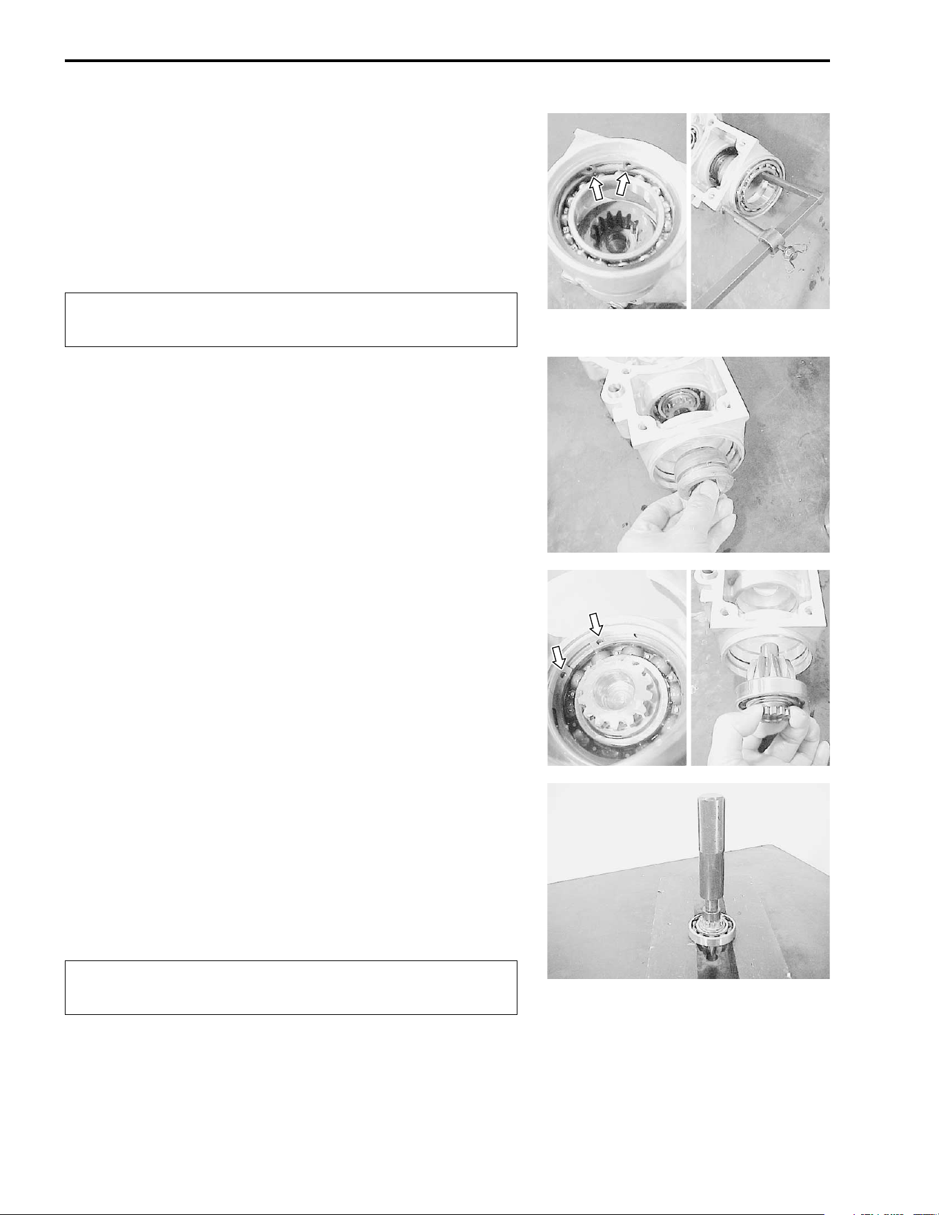
4-6 DRIVE TRAIN
• Remove the snap ring.
• Remove the bearing with the special tool.
# 09913-50121: Oil seal remover
NOTE:
If there is no abnormal condition, the bearing removal is not nec-
essary.
"
• Remove the shifting sleeve.
BEVEL PINION GEAR
• Remove the snap ring.
• Remove the pinion gear together with the bearing.
BEVEL PINION GEAR BEARING
• Remove the bearing from the pinion gear with the special tool.
# 09913-70210: Bearing installer set
NOTE:
If there is no abnormal condition, the bearing removal is not nec-
essary.
"
The removed bearing must be replaced with a new
one.
The removed bearing must be replaced with a new
one.
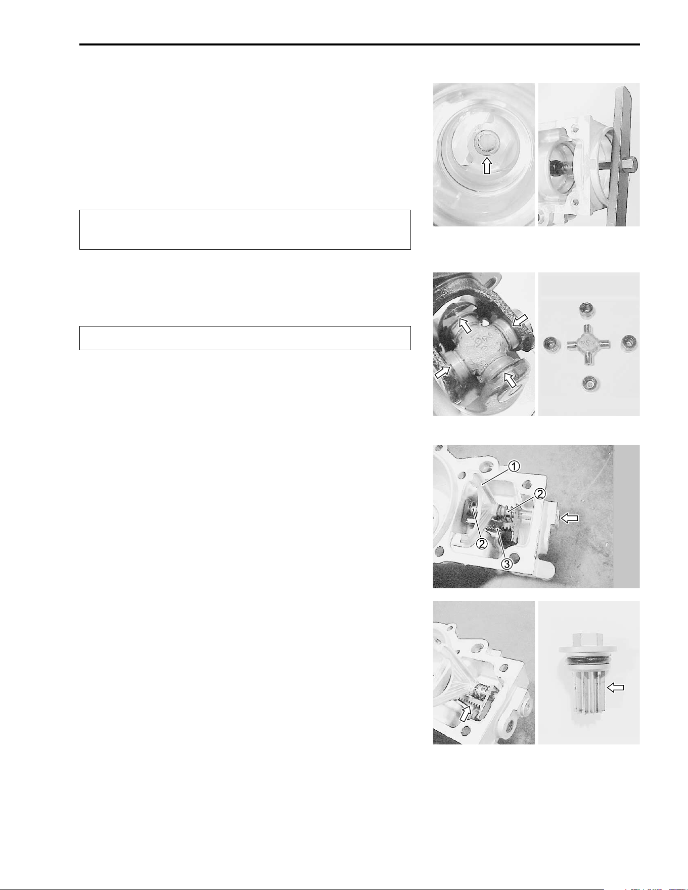
DRIVE TRAIN 4-7
• Remove the pinion gear pilot bearing with the special tools.
# 09921-20240: Bearing remover set
09917-50410: Bearing remover
NOTE:
If there is no abnormal condition, the bearing removal is not nec-
essary.
"
UNIVERSAL JOINT
• Remove the C-rings from the universal joint.
"
• Remove the bearings by tapping with the special tool and
hammer. (!3-66)
# 09913-70210: Bearing installer set
• Remove the universal joint.
2WD/4WD SHIFTING
• Remove the 2WD/4WD shifting fork shaft plug.
• Remove the 2WD/4WD shifting fork
1, springs
2 and shift-
ing rack
3 by removing shaft.
FRONT DRIVE (DIFFERENTIAL) INSPECTION
2WD/4WD SHIFTING
Inspect the shifting fork and its rack-and-pinion for wear and
damage. If any defects are found, replace the shifting fork and
its rack-and-pinion with the new ones.
If the shifting fork is damaged, inspect the groove of the shifting
sleeve.
The removed bearing must be replaced with a new
one.
Replace the removed C-ring with a new one.
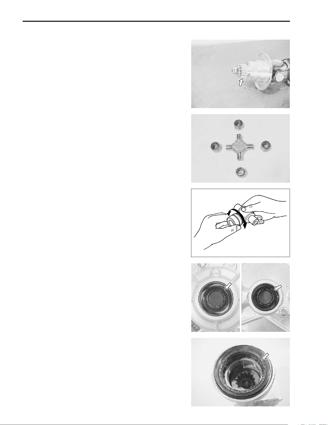
4-8 DRIVE TRAIN
UNIVERSAL JOINT YOKE
Inspect the splines of universal joint for wear or damage. If any
defects are found, replace the universal joint yoke with a new
one.
Inspect the universal joint and outer surface of the bearing for
scuffing, wear and damage. If any defects are found, replace the
bearings and universal joint as a set.
Insert the universal joint to the bearing and check the play by
tuming the universal joint, as shown. If excessive play is noted,
replace the bearing with a new one.
FRONT DRIVE GEAR CASE
Inspect the gear case and case cover oil seals for wear or dam-
age.
If any wear or damage is found, replace the oil seal with a new
one.
OIL SEAL REMOVAL !4-5.
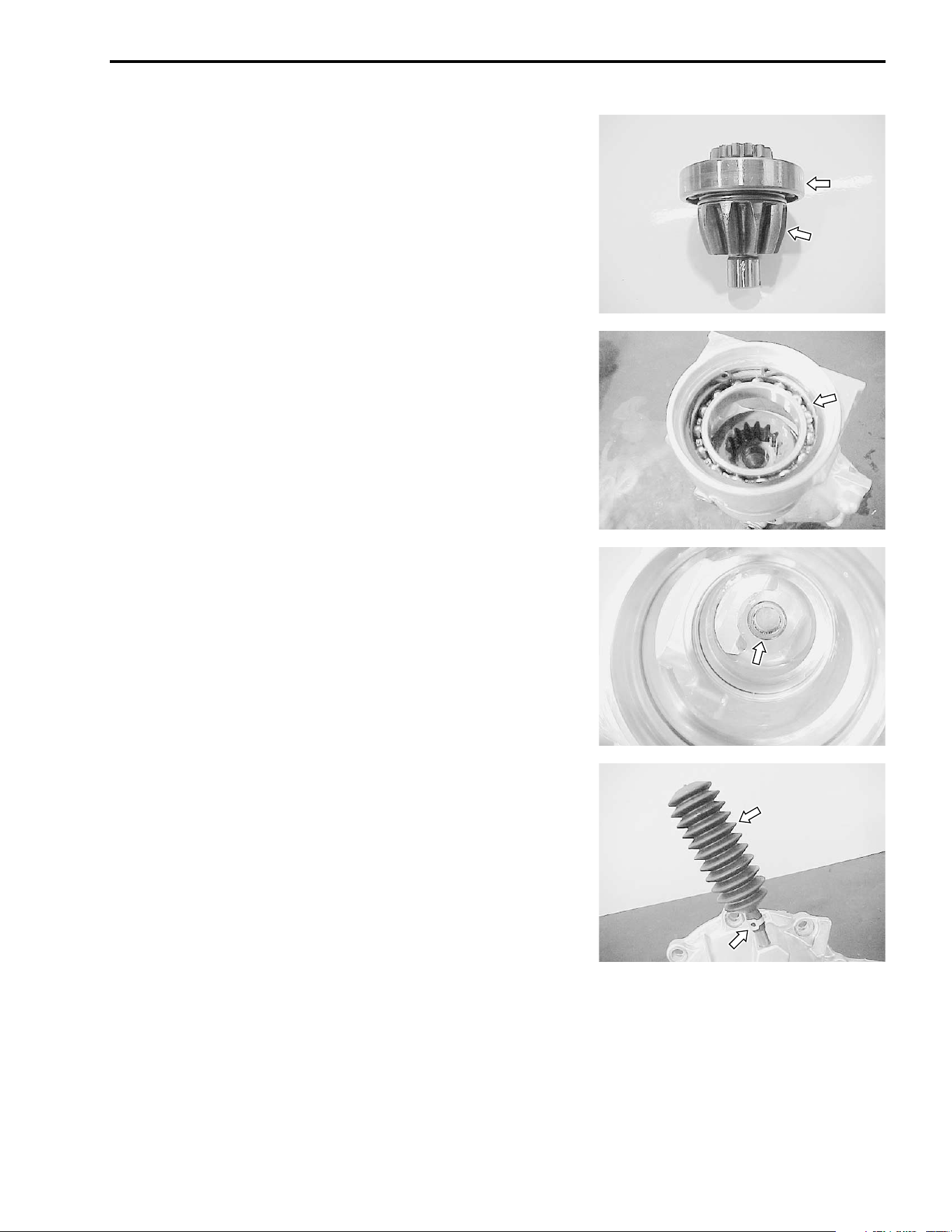
DRIVE TRAIN 4-9
Check the outer race play and smooth rotation of the bearing by
hand while it is on the pinion gear shaft.
Inspect the pinion gear for wear or damage.
If the pinion gear is damaged, inspect the ring gear.
If any defects are found, replace the bearing and gear with the
new ones.
BEARING AND GEAR REMOVAL !4-6.
Check the gear case bearings for wear or damage.
If any wear or damage is found, replace the bearing with a new
one.
BEARING REMOVAL !4-6.
Check the breather rubber case for wear or damage. Also,
check that the joint of the rubber case fits tightly.
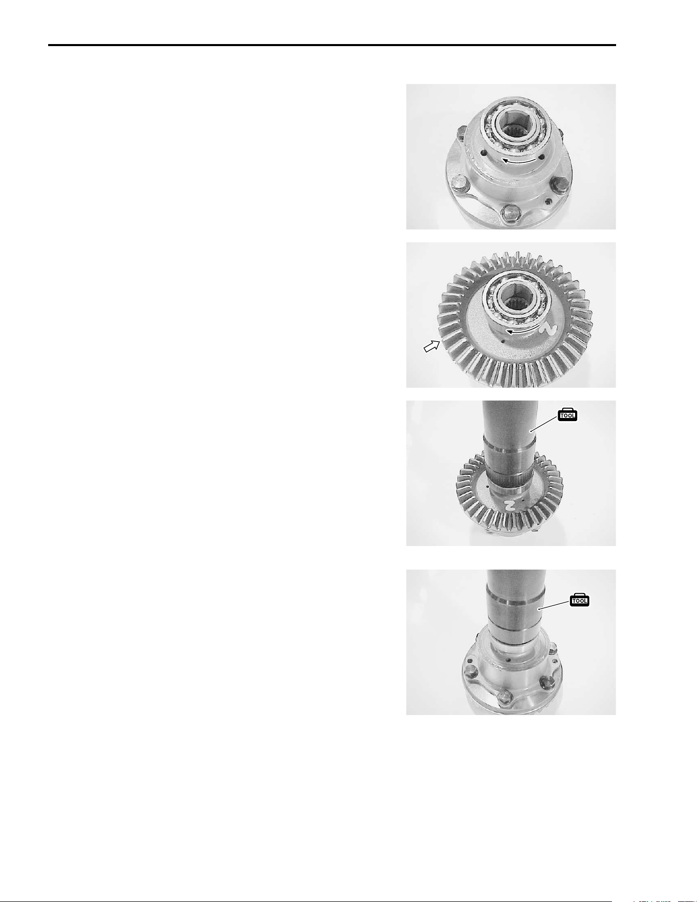
4-10 DRIVE TRAIN
DIFFERENTIAL BEARING/BEVEL RING GEAR
Check the outer race play and smooth rotation of the bearing by
hand while it is on the differential.
Inspect the ring gear for wear or damage.
If the ring gear is damaged, inspect the pinion gear also.
If any defects are found, replace the bearings and ring gear with
the new ones.
BEARING REMOVAL !4-4.
FRONT DRIVE (DIFFERENTIAL) REASSEMBLY
Reassemble the front drive in the reverse order of disassembly.
Pay attention to the following points:
NOTE:
Before reassembly, thoroughly clean all parts in cleaning sol-
vent.
DIFFERENTIAL BEARING
• Drive the bearings to the differential with the special tool.
# 09913-70210: Bearing installer set
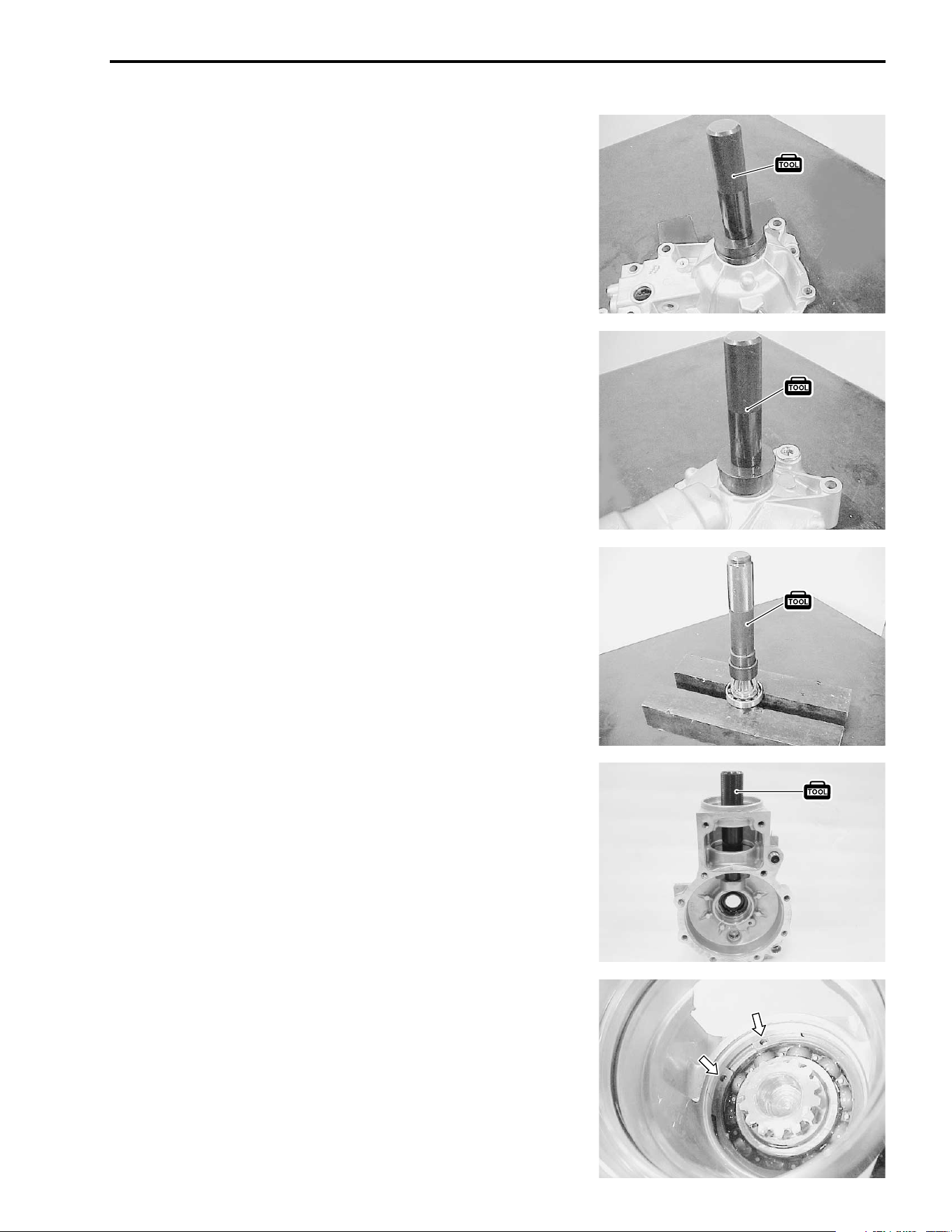
DRIVE TRAIN 4-11
FRONT DRIVE GEAR CASE OIL SEAL
• Install the new oil seals into the gear case and case cover
with the special tool.
• Apply grease to the new oil seal lips.
# 09913-70210: Bearing installer set
$ 99000-25030: SUZUKI SUPER GREASE “A” (USA)
99000-25010: SUZUKI SUPER GREASE “A” (Others)
BEVEL PINION GEAR BEARING
• Drive the bearing onto the shaft with the special tool.
# 09913-70210: Bearing installer set
BEVEL PINION GEAR PILOT BEARING
• Drive the bearing into the gear case with the special tool.
# 09913-70210: Bearing installer set
BEVEL PINION GEAR
• Install the pinion gear assembly and fix the bearing race with
the snap ring.
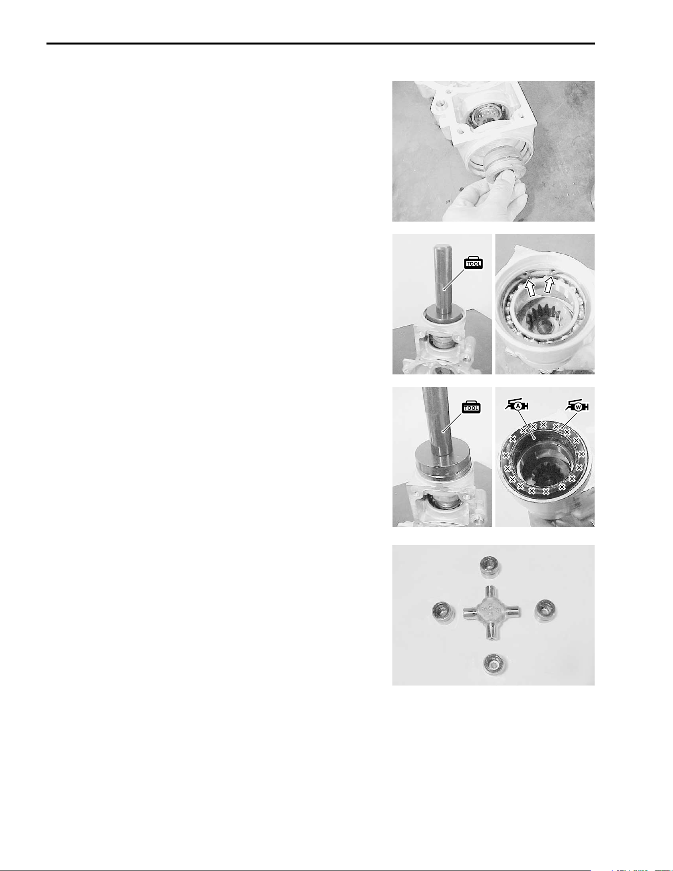
4-12 DRIVE TRAIN
SHIFTING SLEEVE/UNIVERSAL JOINT YOKE
• Install the shifting sleeve to the pinion gear shaft.
• Drive the new bearing into the gear case with the special tool
and fix it with the snap ring.
# 09913-70210: Bearing installer set
• Install the oil seal into the gear case with the special tool.
# 09913-70210: Bearing installer set
• Apply grease to the seal lip groove.
$ 99000-25030: SUZUKI SUPER GREASE “A” (USA)
99000-25010: SUZUKI SUPER GREASE “A” (Others)
• Apply 4 – 5 gram of water resistance grease to the outside of
seal lip groove.
% 99000-25160: WATER RESISTANCE GREASE
• Apply grease to the bearing and dust seal lip.
• Install the universal joint and bearings with the special tool.
(!3-70)
• Install the C-rings by tapping with a copper hammer. (!3-
70)
$ 99000-25030: SUZUKI SUPER GREASE “A” (USA)
99000-25010: SUZUKI SUPER GREASE “A” (Others)
# 09913-70210: Bearing installer set
NOTE:
Reassemble the universal joint in the same manner as the front/
rear output shaft.
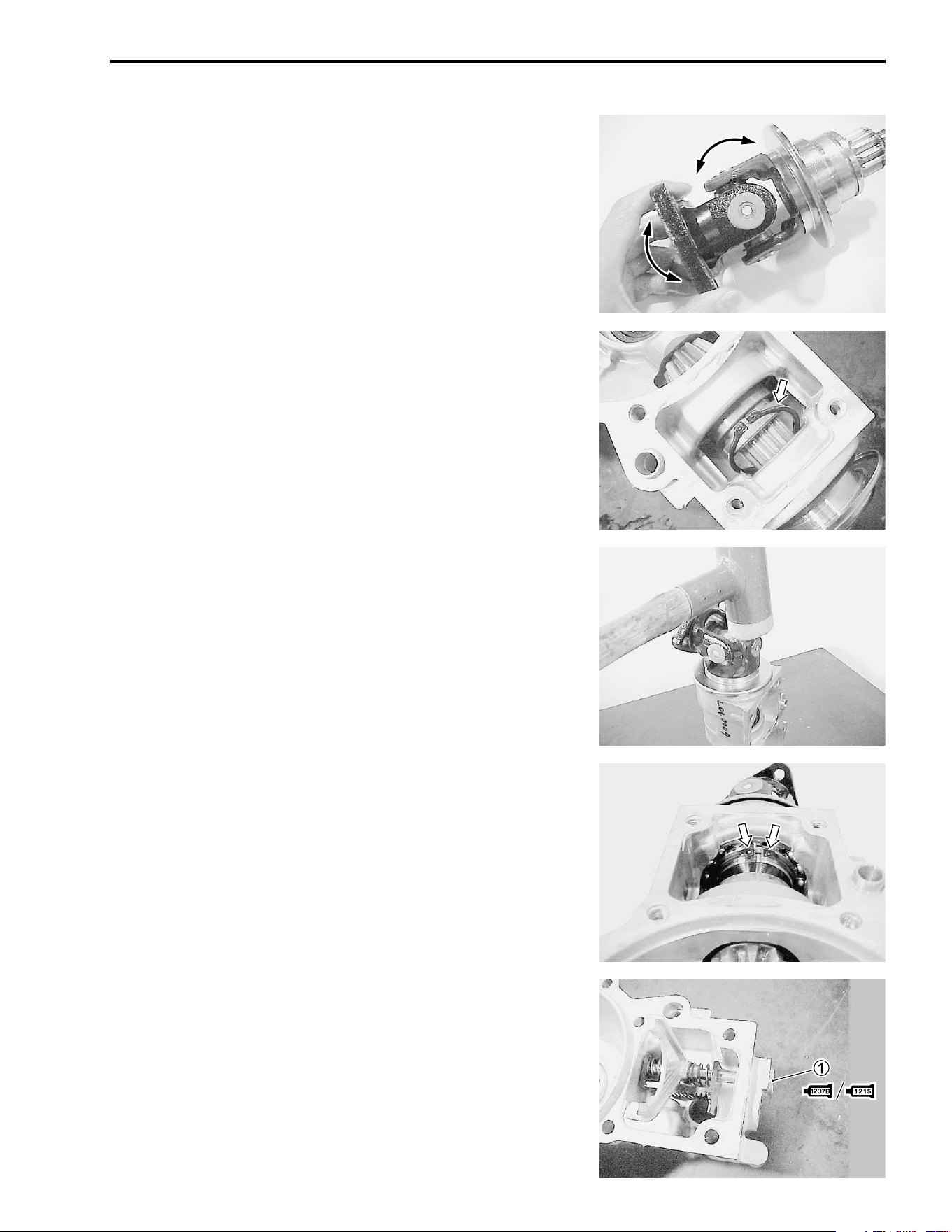
DRIVE TRAIN 4-13
• After reassembling the universal joint, check the joint move-
ment smoothly. If a large resistance is felt to movement, tap
the bearing with a plastic mallet lightly.
• Before installing the universal joint yoke assembly, place the
snap ring between the shifting sleeve and splines of universal
joint.
• Install the universal joint yoke assembly by tapping with a
plastic mallet.
• Fix the universal joint yoke with the snap ring.
2WD/4WD SHIFTING
• Install the 2WD/4WD shifting fork, springs and shifting rack as
shown.
• Apply sealant to the shifting fork shaft plug
1 and tighten it to
the specified torque.
& 99104-31140: SUZUKI BOND “1207B” (USA)
' 99000-31110: SUZUKI BOND “1215” (Others)
( Shifting fork shaft plug: 15 N·m (1.5 kgf-m, 11.0 lb-ft)
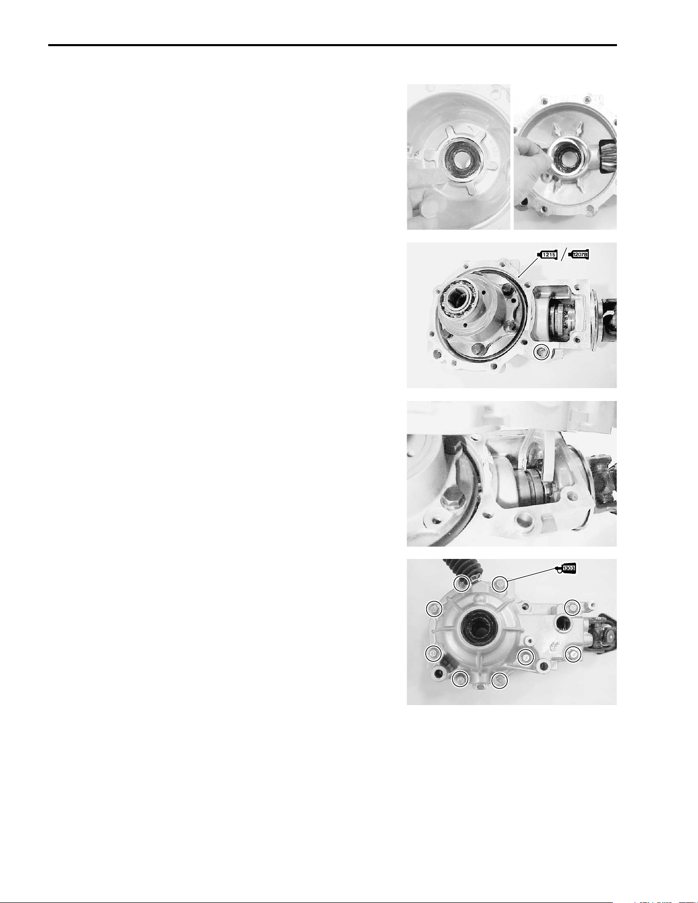
4-14 DRIVE TRAIN
FRONT DRIVE (DIFFERENTIAL) GEAR CASE [FINAL
ASSEMBLY]
• Install the removed shims to the gear case and its cover.
• Install the differential assembly to the gear case.
• Install the dowel pin and apply a sealant to the mating surface
of the case.
& 99104-31140: SUZUKI BOND “1207B” (USA)
' 99000-31110: SUZUKI BOND “1215” (Others)
NOTE:
After the backlash and tooth contact have been checked or
adjusted, apply a sealant to the mating surface of the case.
• When installing the gear case cover, align the shifting fork
with its groove.
• Apply THREAD LOCK SUPER “1303” to the case cover bolts
and tighten them to the specified torque in a crisscross pat-
tern.
) 99000-32030: THREAD LOCK SUPER “1303”
( Gear case cover bolt: 23 N·m (2.3 kgf-m, 16.5 lb-ft)
NOTE:
After the backlash and tooth contact have been checked or
adjusted, apply THREAD LOCK SUPER “1303” to the case
cover bolts.
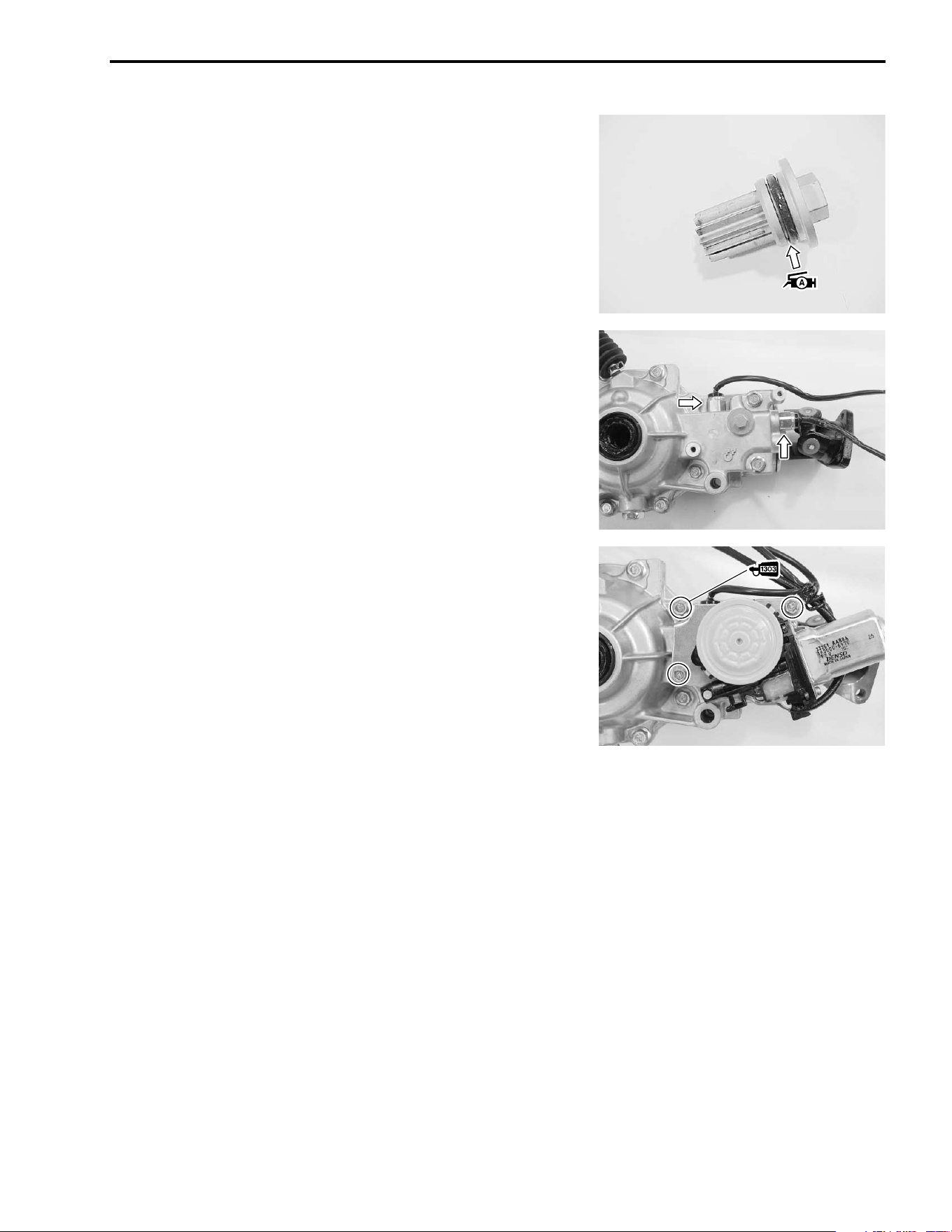
DRIVE TRAIN 4-15
2WD/4WD SHIFTING PINION AND SWITCH
• Coat a new O-ring with grease and install the 2WD/4WD shift-
ing pinion.
• Apply sealant to the 2WD/4WD switches and tighten them to
the specified torque.
& 99104-31140: SUZUKI BOND “1207B” (USA)
' 99000-31110: SUZUKI BOND “1215” (Others)
( 2WD/4WD switch: 22 N·m (2.2 kgf-m, 16.0 lb-ft)
2WD/4WD SHIFTING MOTOR
• Apply THREAD LOCK SUPER “1303” to the M8 bolt.
• Install the 2WD/4WD shifting motor and tighten its mounting
bolts to the specified torque.
) 99000-32030: THREAD LOCK SUPER “1303”
( 2WD/4WD shifting motor mounting bolt
(M8): 23 N·m (2.3 kgf-m, 16.5 lb-ft)
(M6): 12 N·m (1.2 kgf-m, 8.5 lb-ft)
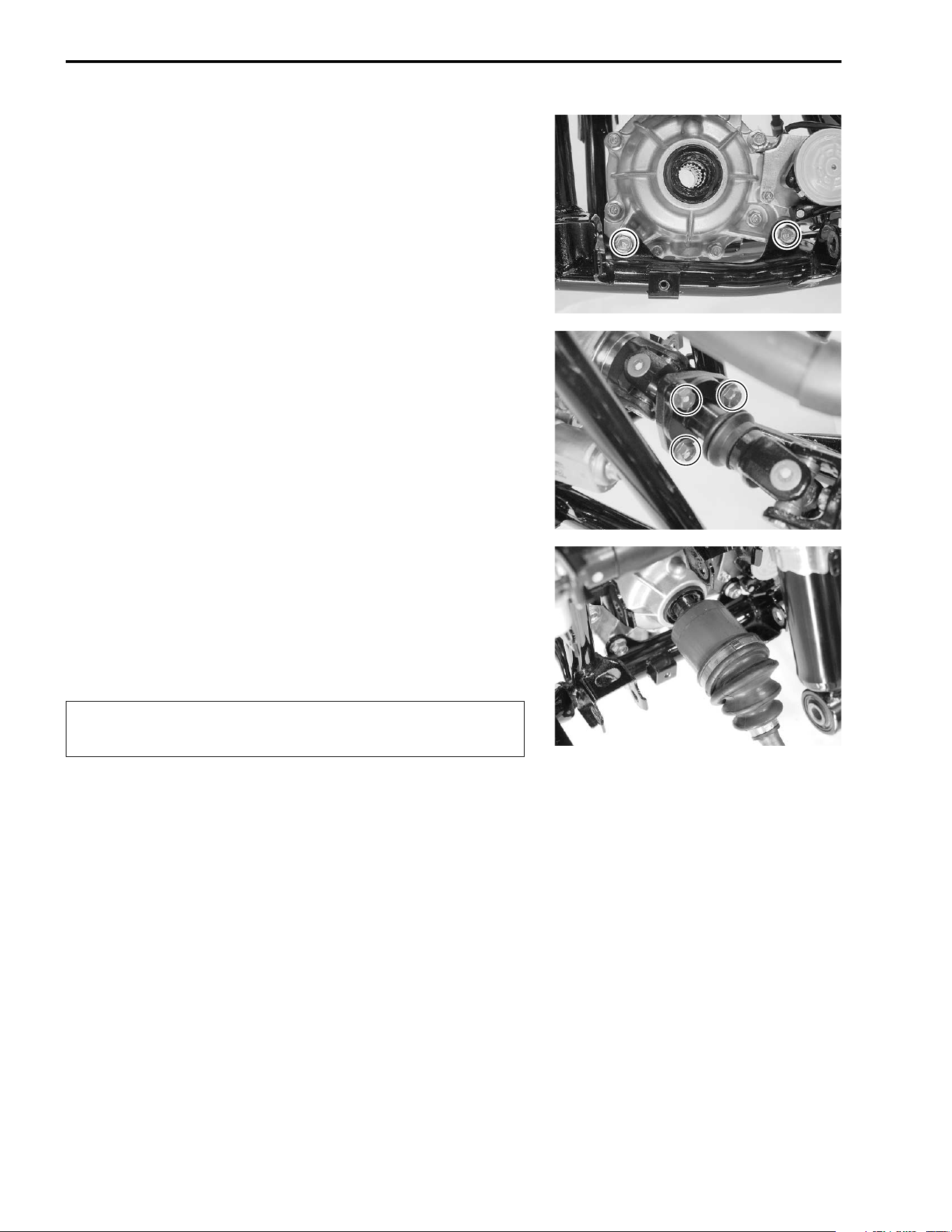
4-16 DRIVE TRAIN
FRONT DRIVE (DIFFERENTIAL)
INSTALLATION
Install the front drive (differential) in the reverse order of
removal. Pay attention to the following points:
• Tighten the front drive (differential) gear case mounting bolts
to the specified torque.
( Front drive gear case mounting bolt:
45 N·m (4.5 kgf-m, 32.5 lb-ft)
• Apply THREAD LOCK SUPER “1303” to the front propeller
shaft flange coupling bolts and tighten them to the specified
torque.
) 99000-32030: THREAD LOCK SUPER “1303”
( Flange coupling bolt: 45 N·m (4.5 kgf-m, 32.5 lb-ft)
NOTE:
Align the match mark on the front propeller shaft. (!3-9)
• Install a new stopper ring into its groove in the splines.
• Apply grease to the splines of the drive shafts and install the
drive shafts to the front drive (differential) gear case.
$ 99000-25030: SUZUKI SUPER GREASE “A” (USA)
99000-25010: SUZUKI SUPER GREASE “A” (Others)
"
NOTE:
After installing both drive shafts, check the stopper rings are
seated properly by pulling on both sides of the inboard joints
lightly.
• Pour the specified hypoid gear oil (SAE #90) in through the
filler hole. (!2-11)
• Install the front suspension. (!7-38)
• Install the front fender. (!7-6)
Be careful not to damage the oil seal in the front drive
(differential) gear case.
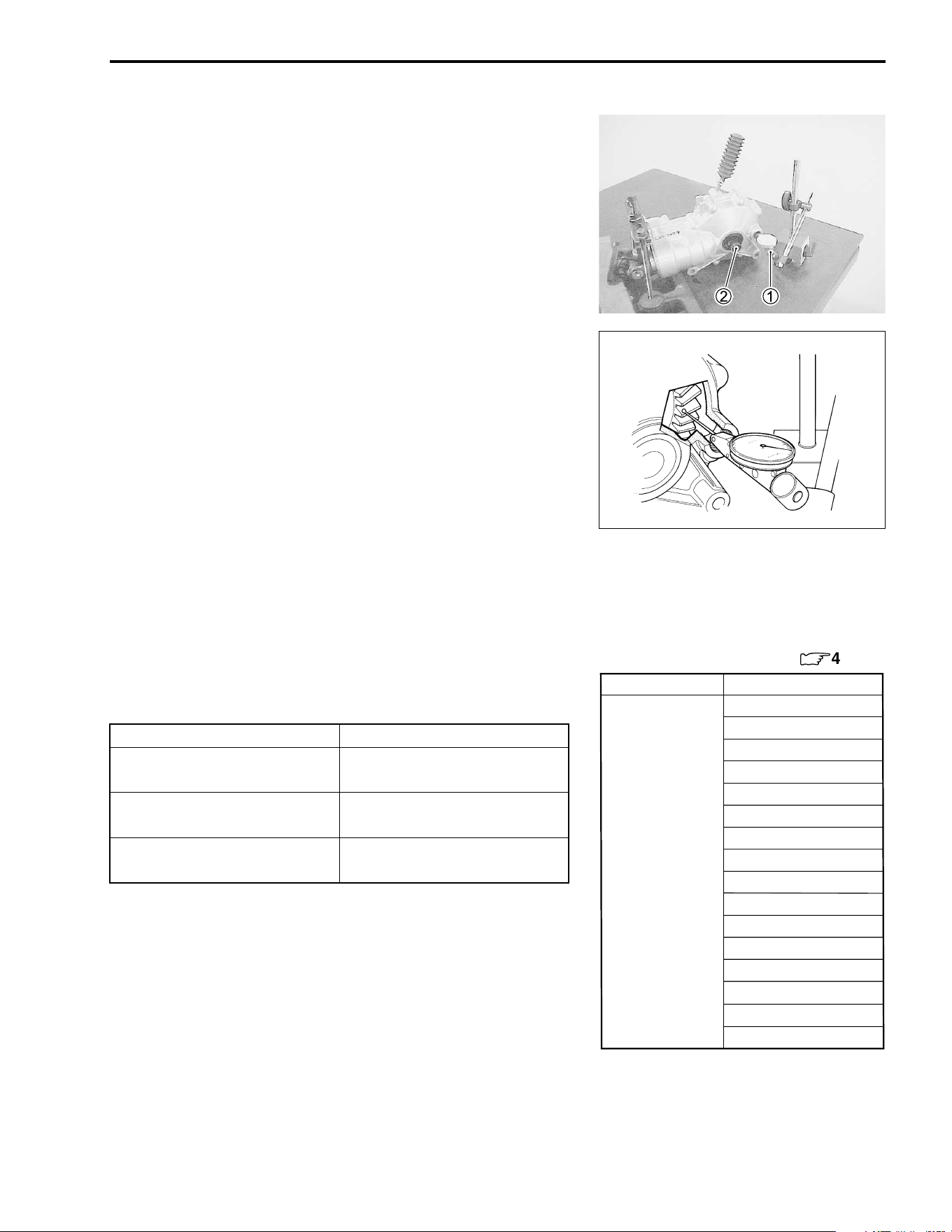
DRIVE TRAIN 4-17
SHIM ADJUSTMENT
BACKLASH
• Install the removed left and right side shims and differential
assembly.
• Assemble the gear case cover. (!4-14)
NOTE:
At this time, it is not necessary to apply a sealant to the mating
surface of the gear case. (!4-14)
Remove the oil filler cap and measure the backlash of the differ-
ential ring gear using the horizontal type dial gauge
1 and
proper size of wooden piece or plastic piece
2, as shown. Take
backlash readings at three places while turning the ring gear
slightly in each direction and securely holding the pinion gear.
Read the total backlash on the dial gauge.
Remove the dial gauge and turn the ring gear 120°, then mea-
sure the backlash. Repeat this procedure once more and com-
pare the difference of the three measurements.
If the backlash is not within specification, the shim must be
changed and the backlash should be re-checked until correct.
Refer to the chart at the right for the appropriate shim thickness.
* Backlash
Standard: 0.05 – 0.10 mm (0.0020 – 0.0040 in)
NOTE:
Adjust the backlash by referring to the chart at the right and
using the thickness of the removed shims as a guide.
If the backlash is too small, replace the right side shim(s) with a
thicker one.
If the backlash is too large, replace the right side shim(s) with a
thinner one.
If the right side shim was changed with a 0.10 mm thicker shim,
replace the left side shim with one that is 0.10 mm thinner.
Backlash Shim adjustment
Under 0.05 mm
(0.0020 in)
Increase shim thickness
0.05 – 0.10 mm
(0.0020 – 0.0040 in)
Correct
Over 0.10 mm
(0.0040 in)
Decrease shim thickness
Part No.
Shim thickness
For differential ring gear (
:
4-20)
0.70 mm (0.0276 in)
0.75 mm (0.0295 in)
0.80 mm (0.0315 in)
0.85 mm (0.0335 in)
0.90 mm (0.0354 in)
0.95 mm (0.0374 in)
1.00 mm (0.0394 in)
27445-38FA0 1.05 mm (0.0413 in)
(Shim set: 16 pcs) 1.10 mm (0.0433 in)
1.15 mm (0.0453 in)
1.20 mm (0.0472 in)
1.25 mm (0.0492 in)
1.30 mm (0.0512 in)
1.35 mm (0.0531 in)
1.40 mm (0.0551 in)
1.45 mm (0.0571 in)
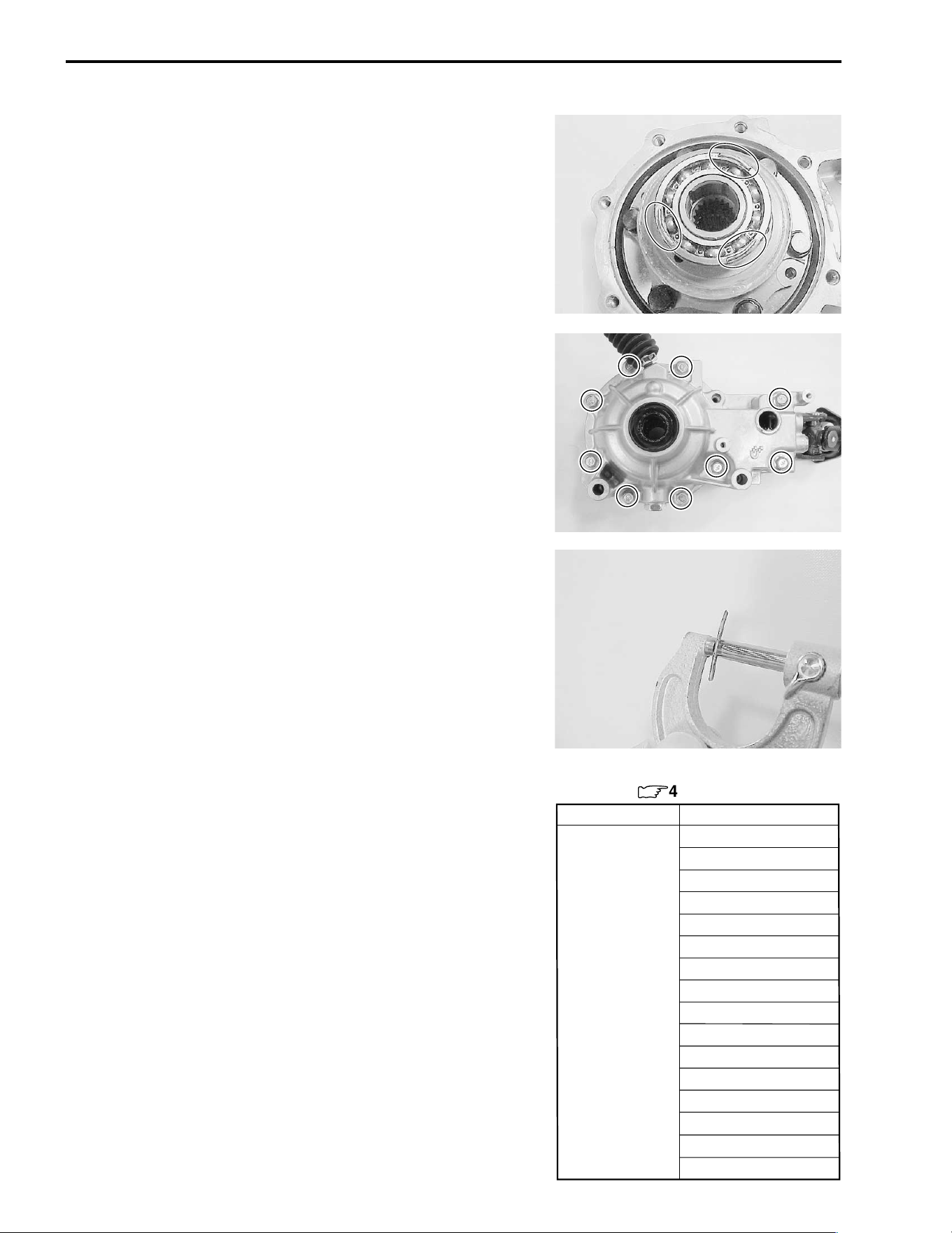
4-18 DRIVE TRAIN
LEFT SIDE SHIM SELECTION
• Install the removed right side shim(s) and differential assem-
bly.
• Put a few pieces of solder (O.D.: 1.2 – 1.5 mm × L: 6 mm) on
the bearing outer race, as shown.
NOTE:
* Do not install the left side shim(s) at this time.
* Apply a small quantity of grease to the solders to prevent them
from falling.
• Assemble the gear case cover and tighten its bolts to the
specified torque in a crisscross pattern. (!4-14)
NOTE:
* Do not apply a sealant to the mating surface of the gear case.
* Do not apply a thread lock to the case cover bolts.
(!4-14)
( Gear case cover bolt: 23 N·m (2.3 kgf-m, 16.5 lb-ft)
• Remove the gear case cover. (!4-4)
• Measure the thickness of compressed solder with the
micrometer.
# 09900-20205: Micrometer
• Select the proper size of shim(s) from the right chart, accord-
ing as the compressed solder thickness.
• After selecting the proper size of shim(s), check or adjust the
backlash and tooth contact.
Part No.
Shim thickness
For left side of differential
ring gear (
:
4-20)
0.70 mm (0.0276 in)
0.75 mm (0.0295 in)
0.80 mm (0.0315 in)
0.85 mm (0.0335 in)
0.90 mm (0.0354 in)
0.95 mm (0.0374 in)
1.00 mm (0.0394 in)
27445-38FA0 1.05 mm (0.0413 in)
(Shim set: 16 pcs) 1.10 mm (0.0433 in)
1.15 mm (0.0453 in)
1.20 mm (0.0472 in)
1.25 mm (0.0492 in)
1.30 mm (0.0512 in)
1.35 mm (0.0531 in)
1.40 mm (0.0551 in)
1.45 mm (0.0571 in)
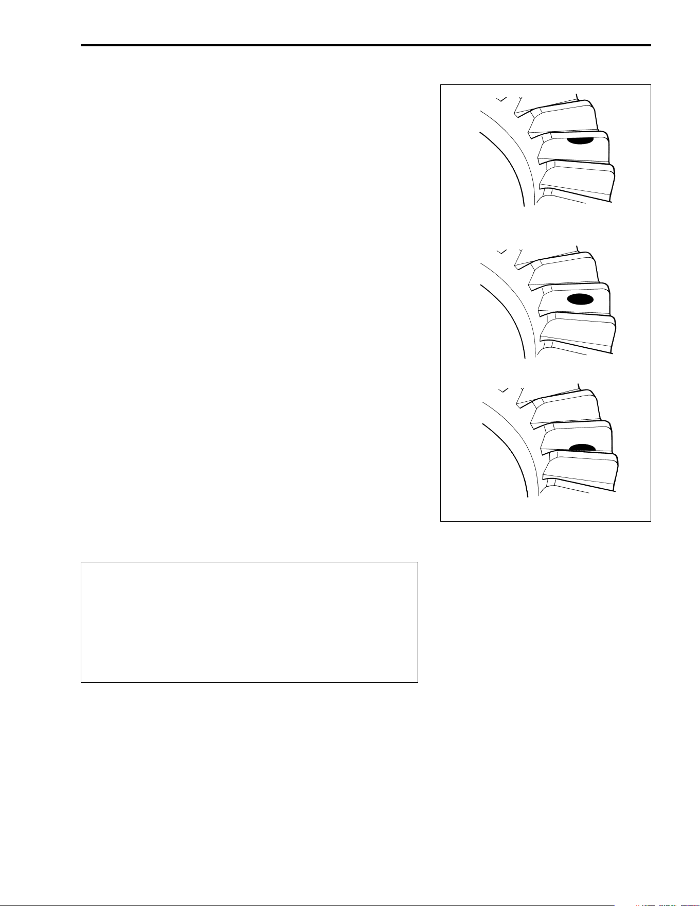
DRIVE TRAIN 4-19
TOOTH CONTACT
After backlash adjustment and left side shim selection are car-
ried out, the tooth contact must be checked. Pay attention to the
following points:
• Remove the differential ring gear.
• Clean and degrease several teeth on the ring gear and pinion
gear, and then apply a coating of machinist’s layout dye or
paste to several teeth of the pinion gear.
• Install the removed left and right side shims and differential
assembly.
• Assemble the gear case cover. (!4-14)
NOTE:
* Do not apply a sealant to the mating surface of the gear case.
* Do not apply a thread lock to the case cover bolts.
(!4-14)
( Gear case cover bolt: 23 N·m (2.3 kgf-m, 16.5 lb-ft)
• Rotate the differential ring gear several turns in each direc-
tion. This will provide a contact pattern on the coated teeth of
ring gear.
• Remove the differential ring gear and compare the coated
teeth to the examples shown in
1,
2 and
3.
• If tooth contact is found to be correct (example
2), go to the
FINAL ASSEMBLY sub-section on p.4-14 to complete instal-
lation.
• If tooth contact is found to be incorrect (example
1 and
3),
the shim must be changed and the tooth contact should be re-
checked until correct.
"
Make sure to check the backlash and shim thickness
after the tooth contact has been adjusted, since it may
have changed. Adjust the tooth contact and backlash
until they are both within specification. If the correct
tooth contact cannot be maintained when adjusting
the backlash, replace the pinion gear and ring gear as
a set.
Incorrect (Contact at tooth top)
Incorrect (Contact at tooth root)
Correct
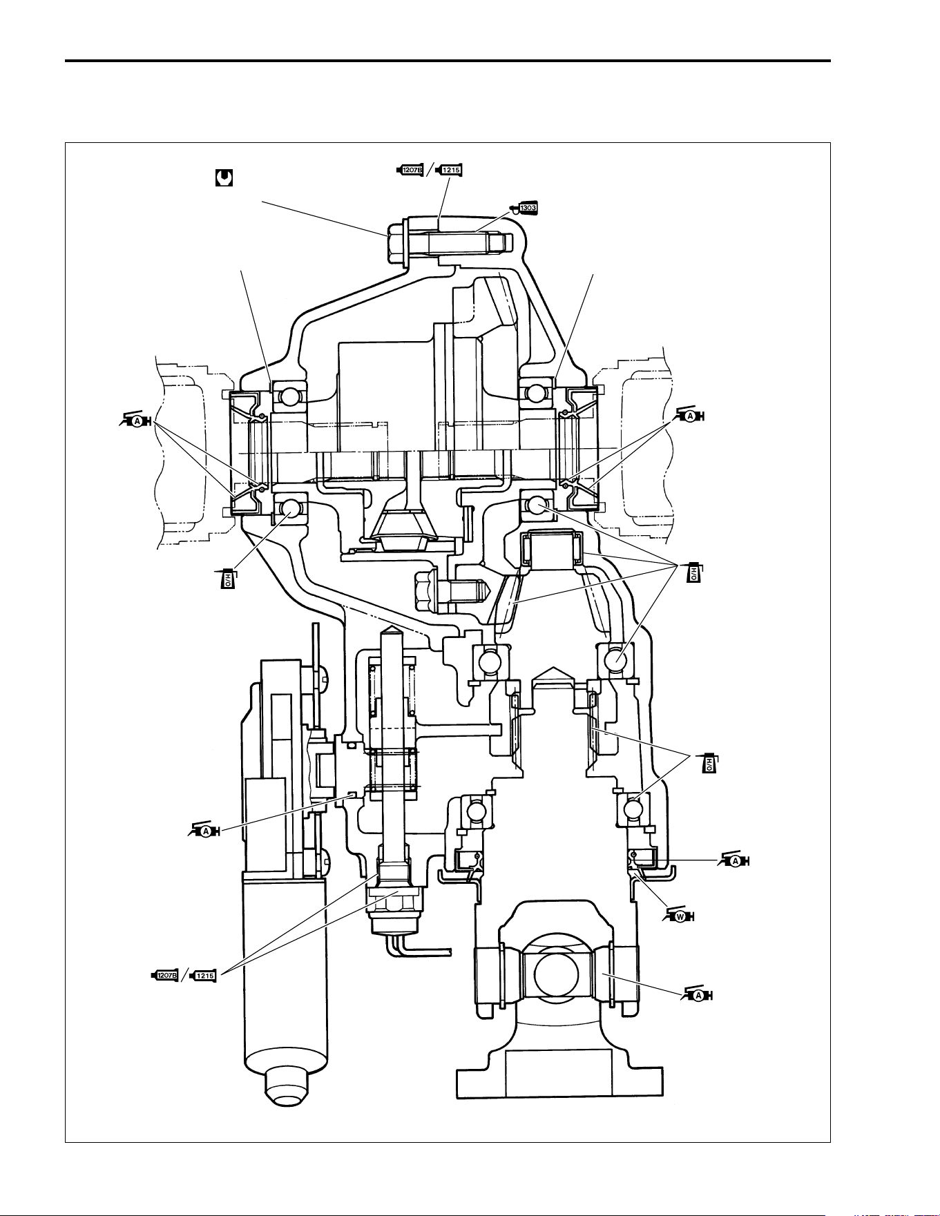
4-20 DRIVE TRAIN
REASSEMBLY INFORMATION
23 N
.
m
(2.3 kgf-m, 16.5 lb-ft)
Mating surfaces
Threaded
parts
4 – 5 gram
Left side of ring gear shim(s)
Right side of ring gear shim(s)
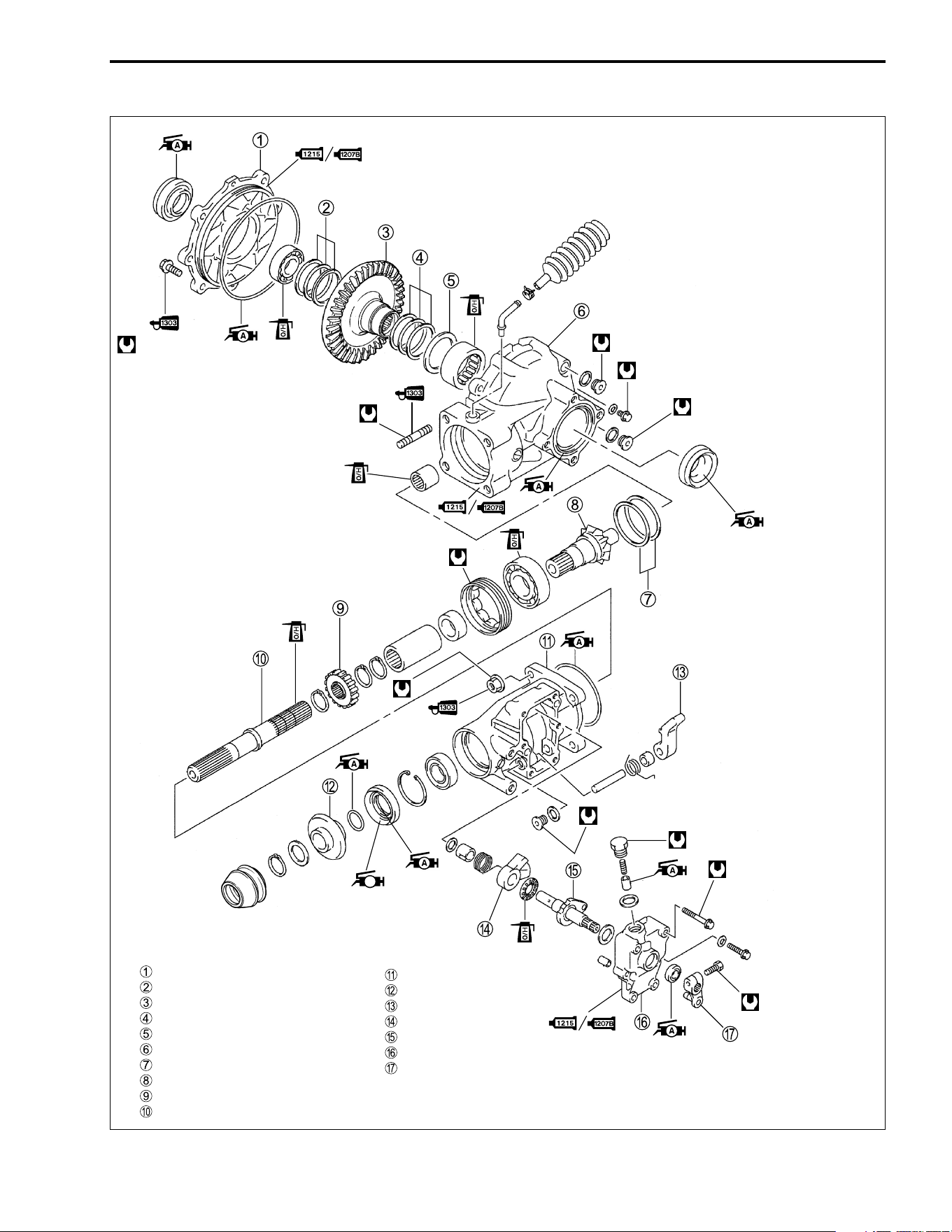
DRIVE TRAIN 4-21
REAR DRIVING SYSTEM
15 N·m (1.5 kgf-m, 11.0 lb-ft)
Rear drive gear case cover
Shim(s), RH
Bevel ring gear
Shim(s), LH
Washer
Rear drive gear case
Shim(s)
Bevel pinion gear
Parking gear
Rear drive shaft
Rear drive shaft housing
Water proof seal
Parking pawl lever
Parking cam
Parking camshaft
Parking cam cover
Parking cam lever
23 N·m
(2.3 kgf-m, 16.5 lb-ft)
33 N·m (3.3 kgf-m, 24.0 lb-ft)
20 N·m (2.0 kgf-m, 14.5 lb-ft)
33 N·m (3.3 kgf-m, 24.0 lb-ft)
23 N·m (2.3 kgf-m, 16.5 lb-ft)
100 N·m (10.0 kgf-m, 72.5 lb-ft)
W
23 N·m (2.3 kgf-m, 16.5 lb-ft)
10 N·m
(1.0 kgf-m, 7.3 lb-ft)
10 N·m
(1.0 kgf-m, 7.3 lb-ft)
23 N·m
(2.3 kgf-m,
(2.3 kgf-m,
16.5 lb-ft)
23 N·m
(2.3 kgf-m,
16.5 lb-ft)
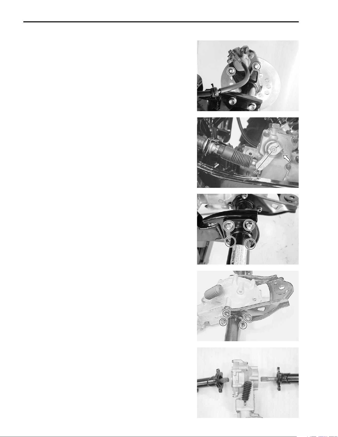
4-22 DRIVE TRAIN
REAR DRIVE REMOVAL
• Drain the gear oil. (!2-11)
• Remove the rear wheels. (!7-11)
• Remove the rear brake caliper.
• Make sure that the parking cam lever is in “P” position.
• Remove the parking cam lever.
• Remove the axle housing mounting bolts, left and right.
• Remove the rear drive gear case together with the axle hous-
ing.
• Remove the axle housing bolts, left and right.
• Remove the rear axle together with the axle housing, left and
right.
P
P
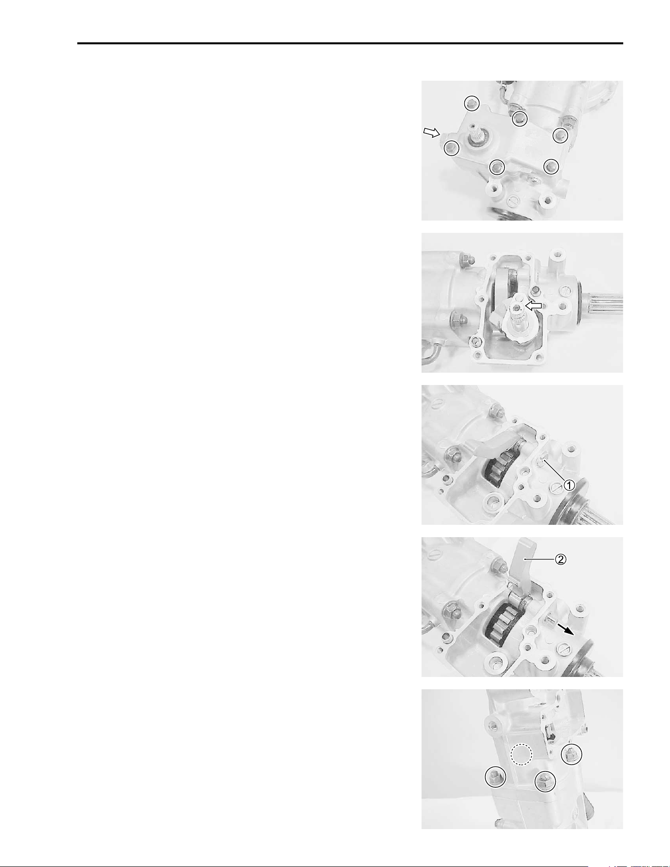
DRIVE TRAIN 4-23
REAR DRIVE DISASSEMBLY
PARKING/REAR DRIVE SHAFT
• Remove the parking cam stopper and cover.
• Remove the parking camshaft assembly.
• Remove the parking pawl lever shaft plug
1.
• Remove the parking pawl lever
2 by removing its shaft.
• Remove the rear drive shaft housing nuts.
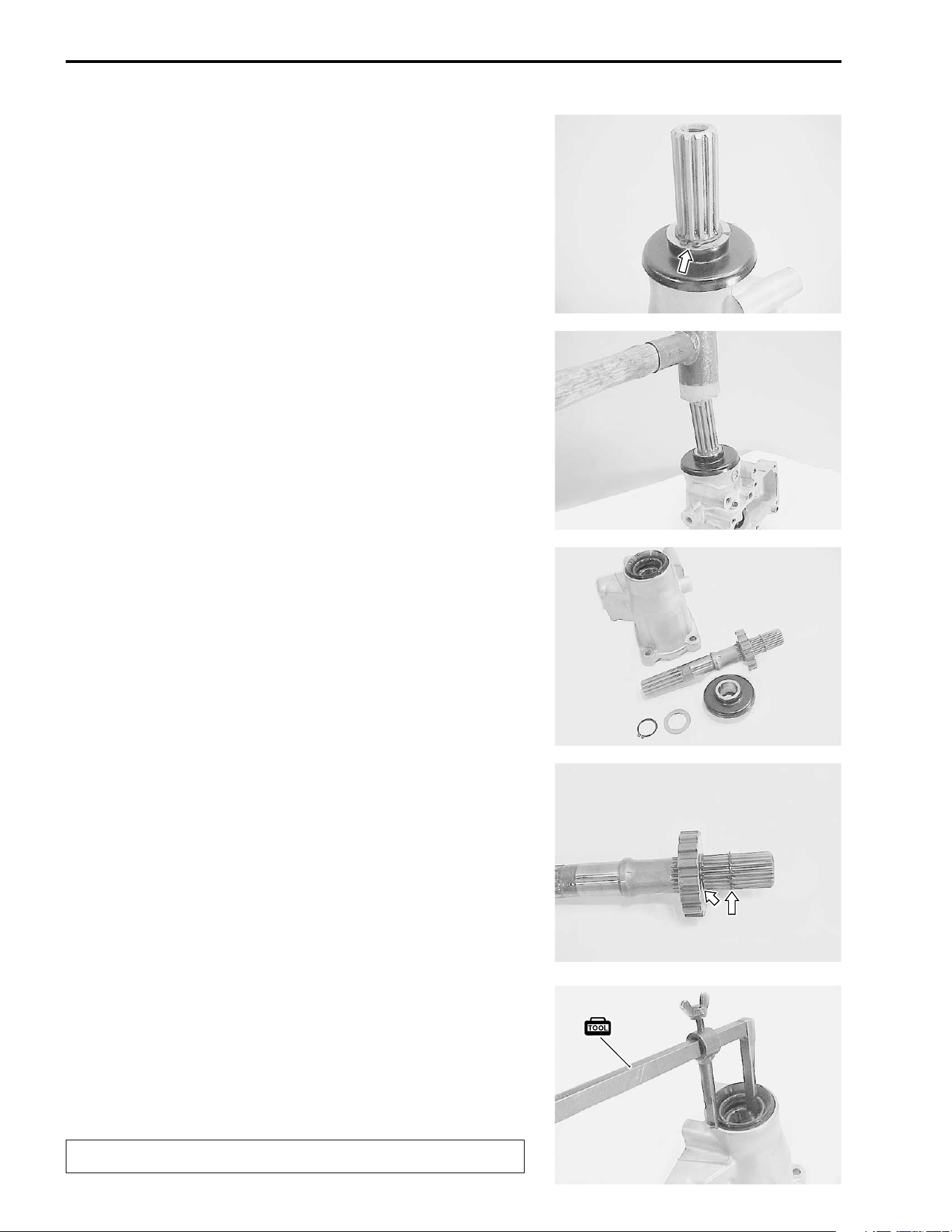
4-24 DRIVE TRAIN
• Remove the snap ring and washer from the drive shaft.
• Remove the drive shaft and waterproof seal by tapping with a
plastic mallet.
• Remove the parking gear by removing the snap rings.
• Remove the oil seal with the special tool.
# 09913-50121: Oil seal remover
NOTE:
If there is no abnormal condition, the oil seal removal is not nec-
essary.
"
The removed oil seal must be replaced with a new one.
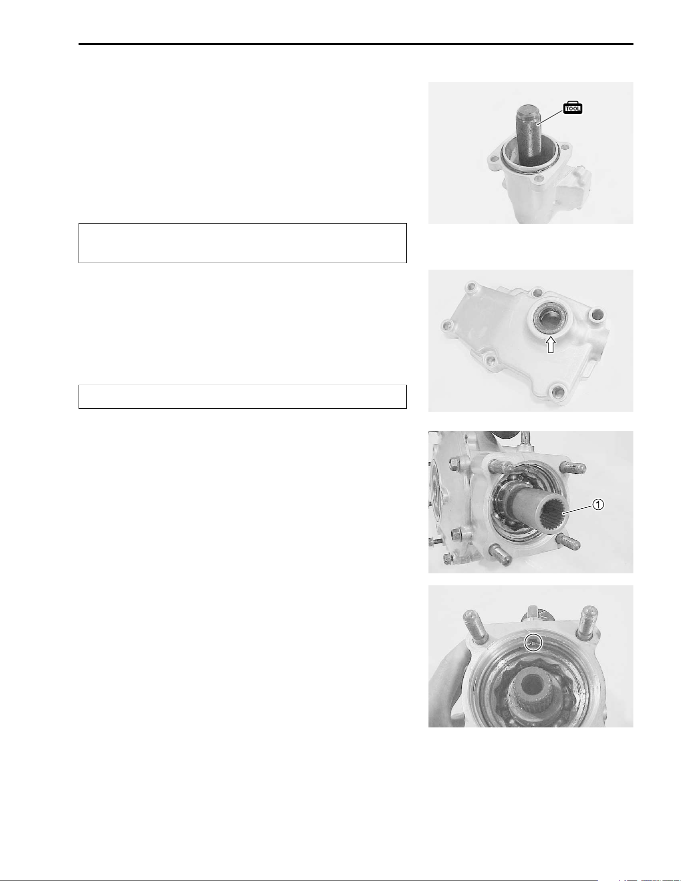
DRIVE TRAIN 4-25
• Remove the snap ring.
• Remove the bearing out of the drive shaft housing with the
special tool.
# 09913-70210: Bearing installer set
NOTE:
If there is no abnormal condition, the bearing removal is not nec-
essary.
"
• Remove the oil seal with the special tool.
# 09913-50121: Oil seal remover
NOTE:
If there is no abnormal condition, the oil seal removal is not nec-
essary.
"
REAR DRIVE GEAR CASE
• Remove the rear drive shaft coupling joint
1.
• Unstake the bearing locknut with a small chisel or drill.
The removed bearing must be replaced with a new
one.
The removed oil seal must be replaced with a new one.
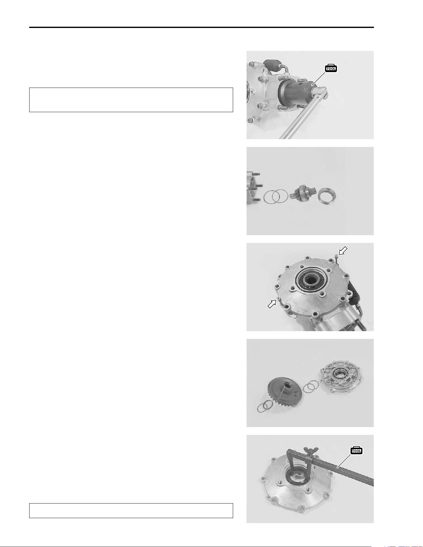
4-26 DRIVE TRAIN
• Remove the bearing locknut with the special tool.
# 09924-41830: Bearing lock nut wrench
"
• Remove the pinion gear assembly and shims out of the case.
• Remove the eight case cover bolts diagonally and evenly.
• Pry the case cover with 5 mm screws as shown.
• Remove the ring gear, shims and washer.
• Remove the oil seal out of the cover with the special tool.
# 09913-50121: Oil seal remover
NOTE:
If there is no abnormal condition, the oil seal removal is not nec-
essary.
"
The removed locknut must be replaced with a new
one.
The removed oil seal must be replaced with a new one.
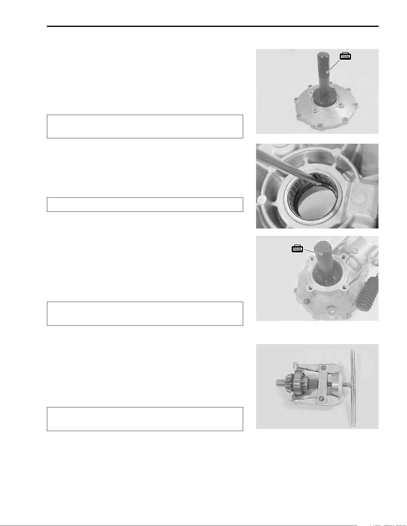
DRIVE TRAIN 4-27
• Remove the bearing out of the cover with the special tool.
# 09913-70210: Bearing installer set
NOTE:
If there is no abnormal condition, the bearing removal is not nec-
essary.
"
• Remove the oil seal out of the case with a suitable tool.
NOTE:
If there is no abnormal condition, the oil seal removal is not nec-
essary.
"
• Remove the bearing out of the case with the special tool.
# 09913-70210: Bearing installer set
NOTE:
If there is no abnormal condition, the bearing removal is not nec-
essary.
"
• Remove the bearing from the shaft with a commercially avail-
able bearing puller or hydraulic press.
NOTE:
If there is no abnormal condition, the bearing removal is not nec-
essary.
"
The removed bearing must be replaced with a new
one.
The removed oil seal must be replaced with a new one.
The removed bearing must be replaced with a new
one.
The removed bearing must be replaced with a new
one.
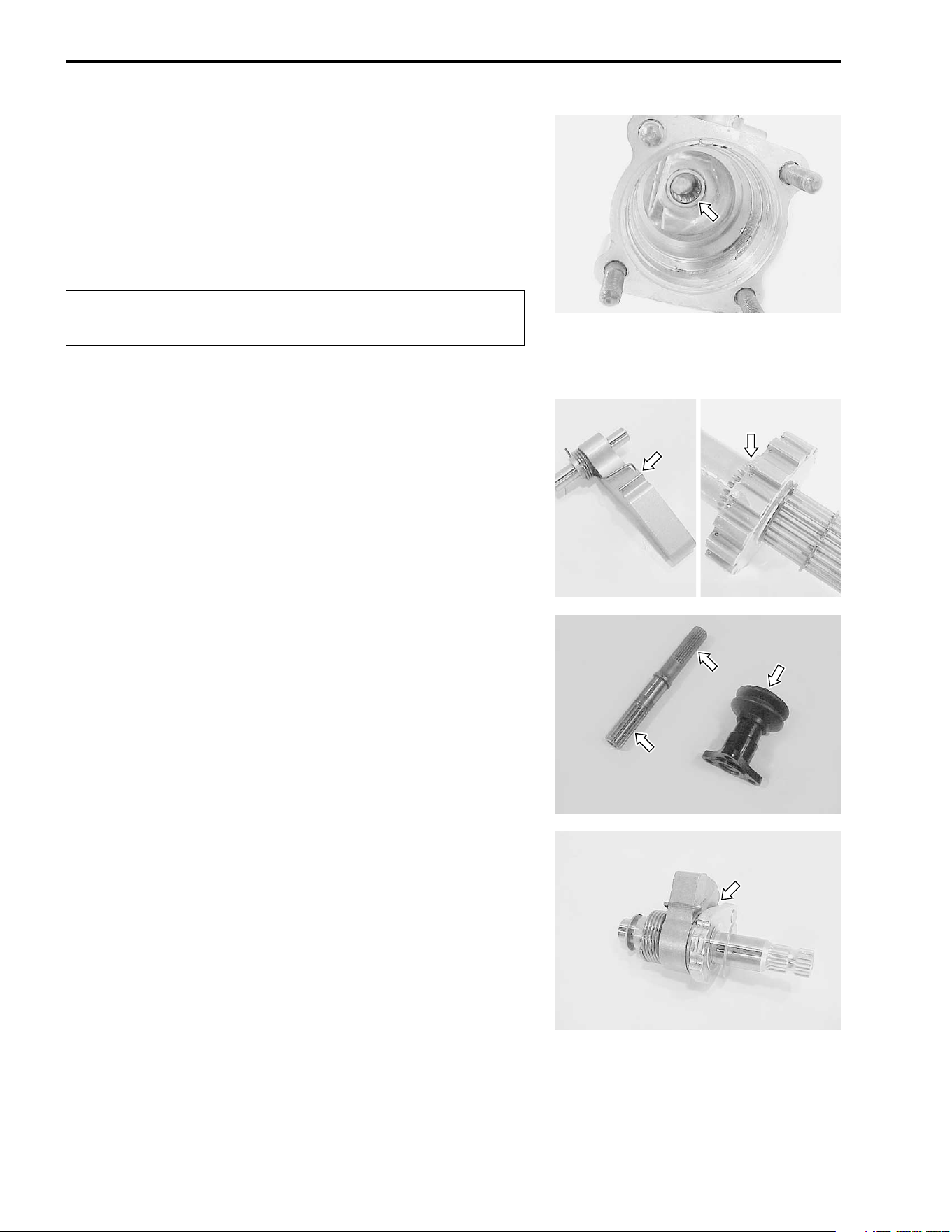
4-28 DRIVE TRAIN
• Remove the pinion gear pilot bearing with the special tools.
# 09921-20240: Bearing remover set
09917-50410: Bearing remover
NOTE:
If there is no abnormal condition, the bearing removal is not nec-
essary.
"
REAR DRIVE INSPECTION
PARKING/REAR DRIVE SHAFT
Inspect the parking pawl and parking gear for wear and damage.
If any defects are found, replace the pawl and gear as a set.
PARKING PAWL AND PARKING GEAR REMOVAL !4-23,
24.
Inspect the splines of rear drive shaft and its coupling joints for
wear or damage.
Also, inspect the boot for cuts or damage.
If any defects are found, replace the rear drive shaft and cou-
pling joint with the new ones.
Inspect the parking cam, thrust bearing and return spring for any
flaws or damage. If any defects are found, replace the cam, ber-
ing and spring with the new ones.
PARKING CAMSHAFT REMOVAL !4-23.
The removed bearing must be replaced with a new
one.
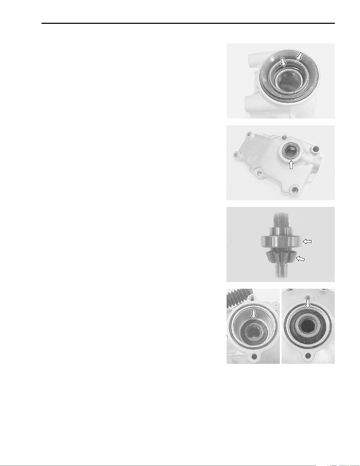
DRIVE TRAIN 4-29
Inspect the oil seal for wear or damage.
Check the inner race play and smooth rotation of the bearing by
hand while it is in the case.
If any defects are found, replace the oil seal and bearing with the
new ones.
OIL SEAL AND BEARING REMOVAL !4-25.
Inspect the parking cam cover oil seal for wear or damage.
If any wear or damage is found, replace the oil seal with a new
one.
OIL SEAL REMOVAL !4-25.
REAR DRIVE GEAR CASE
Check the outer race play and smooth rotation of the bearing by
hand while it is on the pinion gear shaft.
Inspect the pinion gear for wear or damage.
If the pinion gear is damaged, inspect the ring gear also.
If any defects are found, replace the bearing and gear with the
new ones.
BEARING AND GEAR REMOVAL !4-28.
Inspect the gear case and case cover oil seals for wear or dam-
age.
If any wear or damage is found, replace the oil seal with a new
one.
OIL SEAL REMOVAL !4-27.
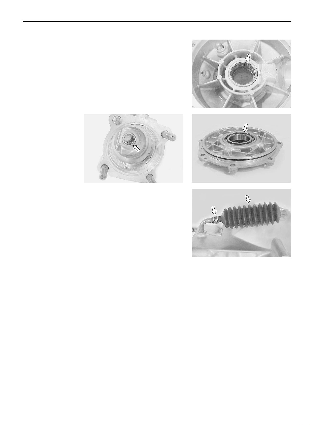
4-30 DRIVE TRAIN
Check the gear case and case cover bearings for wear or dam-
age.
If any wear or damage is found, replace the bearing with a new
one.
BEARING REMOVAL !4-27, 28.
Check the breather rubber case for wear or damage. Also check
that the joint of the rubber case fits tightly.
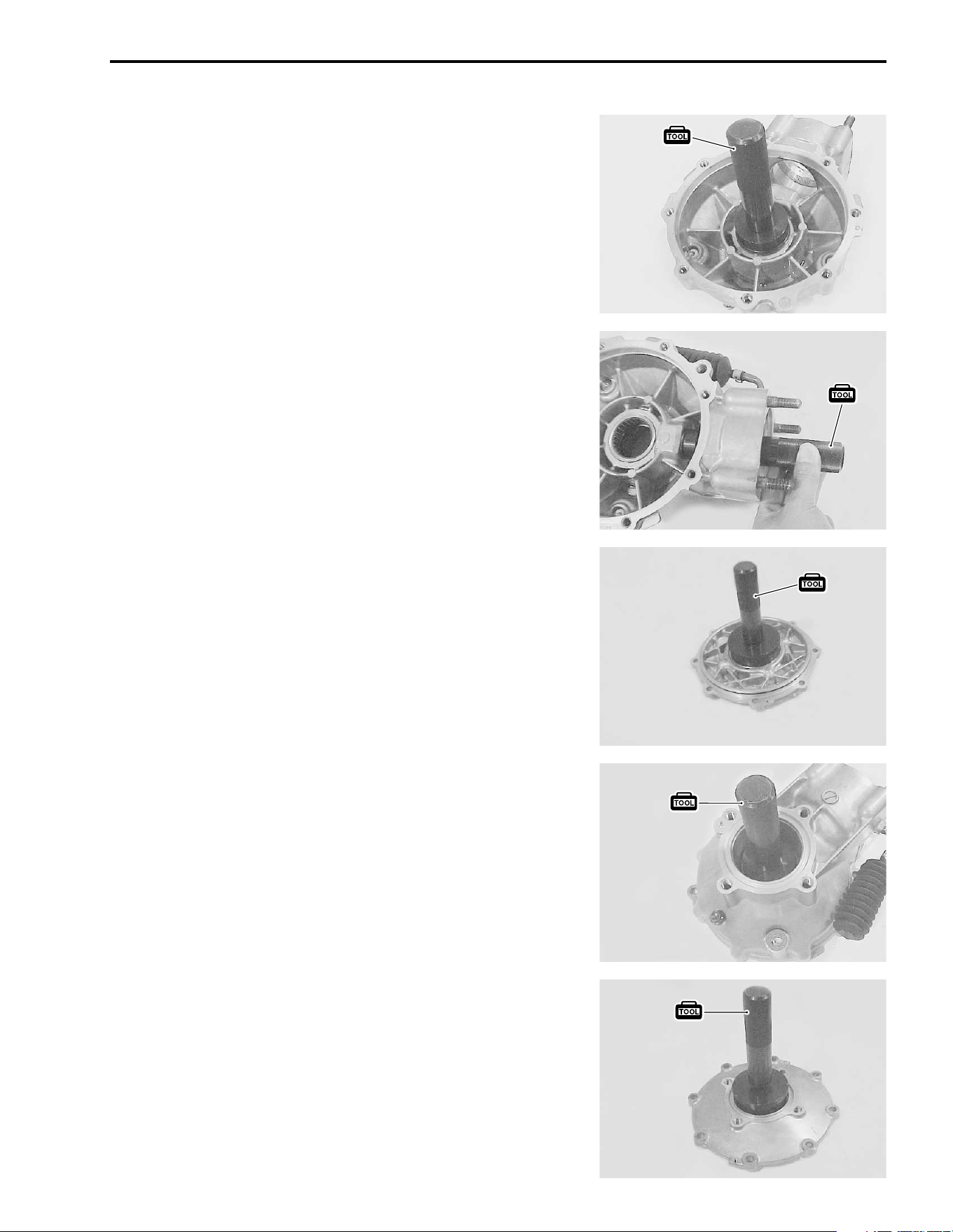
DRIVE TRAIN 4-31
REAR DRIVE REASSEMBLY
Reassemble the rear drive in the reverse order of disassembly.
Pay attention to the following points:
NOTE:
Before reassembly, thoroughly clean all parts in cleaning sol-
vent.
GEAR CASE BEARING
• Drive the bearings into the gear case and case cover with the
special tool.
# 09913-70210: Bearing installer set
GEAR CASE OIL SEAL
• Install the new oil seals into the gear case and case cover
with the special tool.
• Apply grease to the new oil seal lips.
# 09913-70210: Bearing installer set
$ 99000-25030: SUZUKI SUPER GREASE “A” (USA)
99000-25010: SUZUKI SUPER GREASE “A” (Others)
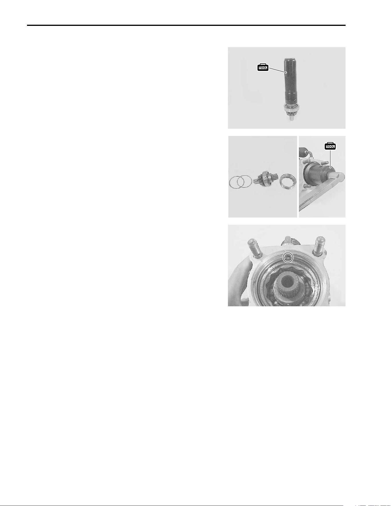
4-32 DRIVE TRAIN
BEVEL PINION GEAR SHAFT BEARING/LOCKNUT
• Drive the bearing onto the shaft with the special tool.
# 09913-70210: Bearing installer set
BEVEL PINION GEAR/SHIM [FINAL ASSEMBLY]
• Install the shims, pinion gear assembly and bearing lock-
nut.
• Tighten the new locknut to the specified torque.
# 09924-41830: Bearing locknut wrench
( Bearing locknut: 100 N·m (10.0 kgf-m, 72.5 lb-ft)
NOTE:
After the backlash and tooth contact have been checked or
adjusted, stake the nut with a center punch.
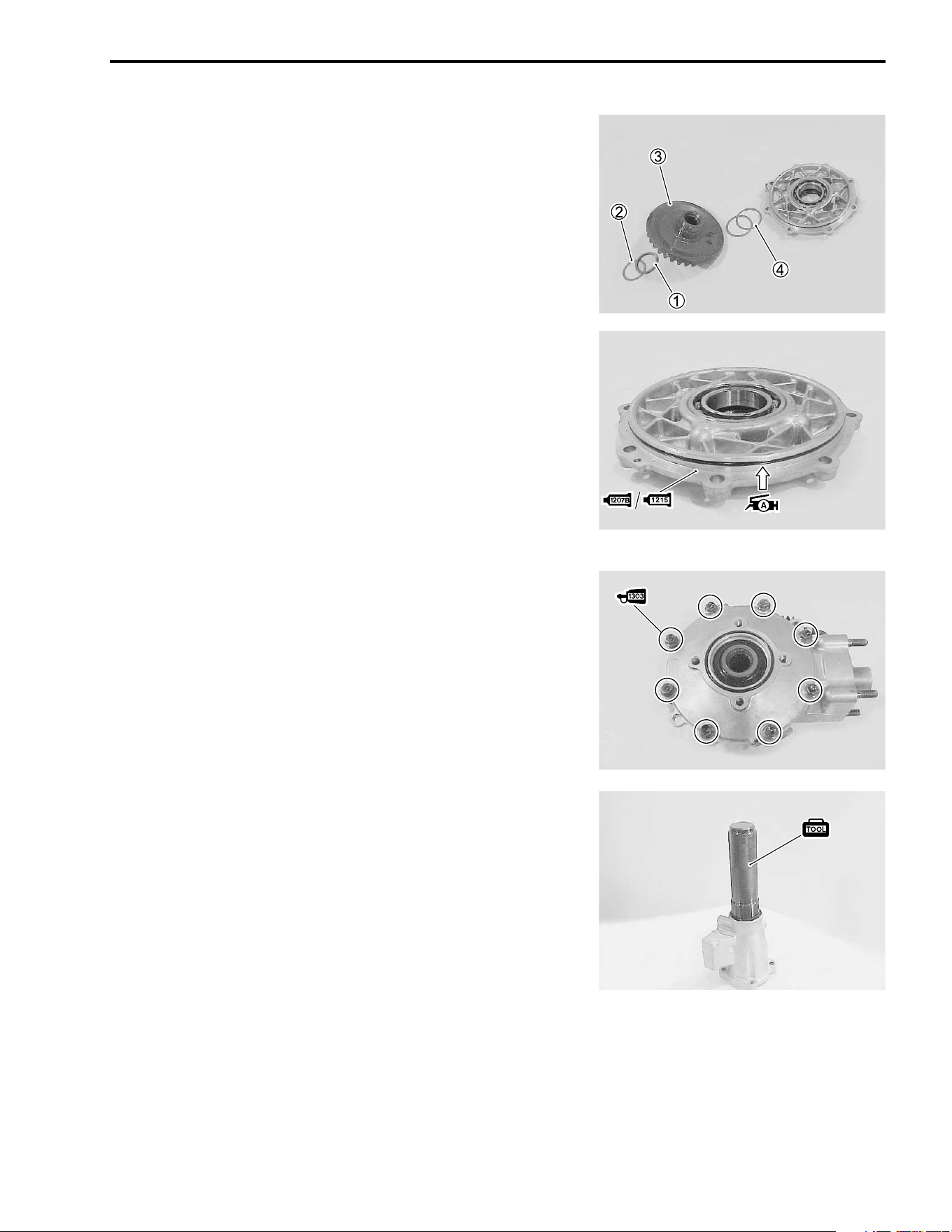
DRIVE TRAIN 4-33
BEVEL RING GEAR/SHIM
• Place the removed washer
1 and shim(s)
2 on the gear
case bearing (at the left bearing), then install the ring gear
3
and removed shim(s)
4.
GEAR CASE COVER/GEAR CASE [FINAL ASSEMBLY]
• Coat a new O-ring with grease and apply sealant to the mat-
ing surface of the cover, then install the gear case cover.
$ 99000-25030: SUZUKI SUPER GREASE “A” (USA)
99000-25010: SUZUKI SUPER GREASE “A” (Others)
& 99104-31140: SUZUKI BOND “1207B” (USA)
' 99000-31110: SUZUKI BOND “1215” (Others)
NOTE:
After the backlash and tooth contact have been checked or
adjusted, install a new O-ring and apply sealant.
• Apply THREAD LOCK SUPER “1303” to the case cover bolts
and tighten them to the specified torque in a crisscross pat-
tern.
) 99000-32030: THREAD LOCK SUPER “1303”
( Gear case cover bolt: 23 N·m (2.3 kgf-m, 16.5 lb-ft)
NOTE:
After the backlash and tooth contact have been checked or
adjusted, apply THREAD LOCK SUPER “1303” to the case
cover bolts.
REAR DRIVE SHAFT/ PARKING
• Drive the new bearing into the rear drive shaft housing, then
install the new snap ring into its groove properly.
• Install the oil seal into the rear drive shaft housing.
# 09913-70210: Bearing installer set
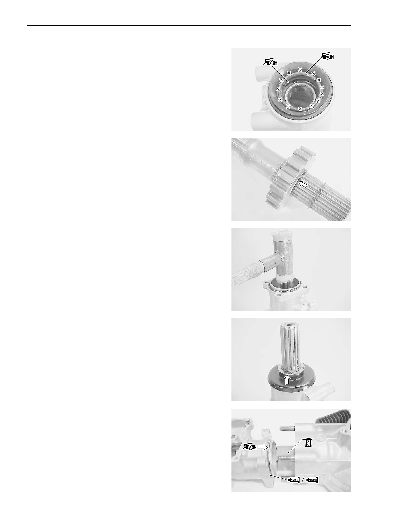
4-34 DRIVE TRAIN
• Apply grease to the seal lip groove.
$ 99000-25030: SUZUKI SUPER GREASE “A” (USA)
99000-25010: SUZUKI SUPER GREASE “A” (Others)
• Apply 4 – 5 gram of water resistance grease to the outside of
seal lip groove.
%99000-25160: WATER RESISTANCE GREASE
• Fix the parking gear with the new snap rings.
• Install the drive shaft into its housing by tapping with a plastic
mallet.
• Apply grease to the new O-ring in the waterproof seal’s collar.
• Install the waterproof seal with collar and washer, then install
the new snap ring.
$ 99000-25030: SUZUKI SUPER GREASE “A” (USA)
99000-25010: SUZUKI SUPER GREASE “A” (Others)
• Apply hypoid gear oil to the coupling joint splines and install
the coupling joint to the pinion gear shaft.
• Coat a new O-ring with grease and apply sealant to the mat-
ing surface of the housing, then install the rear drive shaft
housing.
$ 99000-25030: SUZUKI SUPER GREASE “A” (USA)
99000-25010: SUZUKI SUPER GREASE “A” (Others)
& 99104-31140: SUZUKI BOND “1207B” (USA)
' 99000-31110: SUZUKI BOND “1215” (Others)
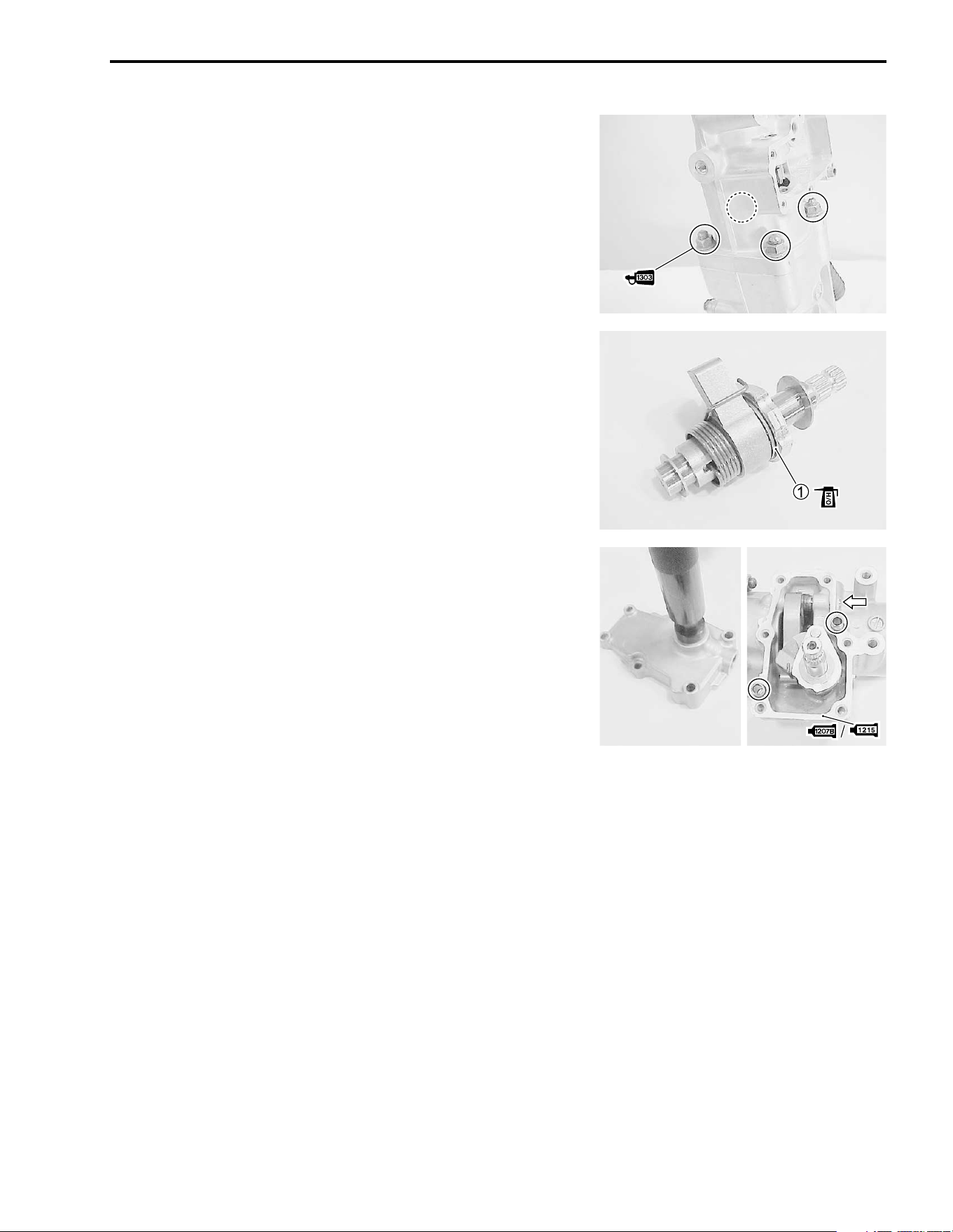
DRIVE TRAIN 4-35
• Apply THREAD LOCK SUPER “1303” to the rear drive shaft
housing nuts and tighten them to the specified torque.
) 99000-32030: THREAD LOCK SUPER “1303”
( Final drive shaft housing nut:
23 N·m (2.3 kgf-m, 16.5 lb-ft)
• Apply hypoid gear oil to the parking camshaft thrust bearing
1.
• Install the new oil seal to the parking cam cover with the spe-
cial tool, and then apply grease to the seal lip.
# 09913-70210: Bearing installer set
$ 99000-25030: SUZUKI SUPER GREASE “A” (USA)
99000-25010: SUZUKI SUPER GREASE “A” (Others)
• Install the parking pawl lever and parking camshaft assembly.
• Install the parking pawl lever shaft plug with a new sealing
washer and tighten the plug to the specified torque.
( Parking pawl lever shaft plug:
15 N·m (1.5 kgf-m, 11.0 lb-ft)
• Install the dowel pins and apply sealant to the mating surface
of the cover.
& 99104-31140: SUZUKI BOND “1207B” (USA)
' 99000-31110: SUZUKI BOND “1215” (Others)
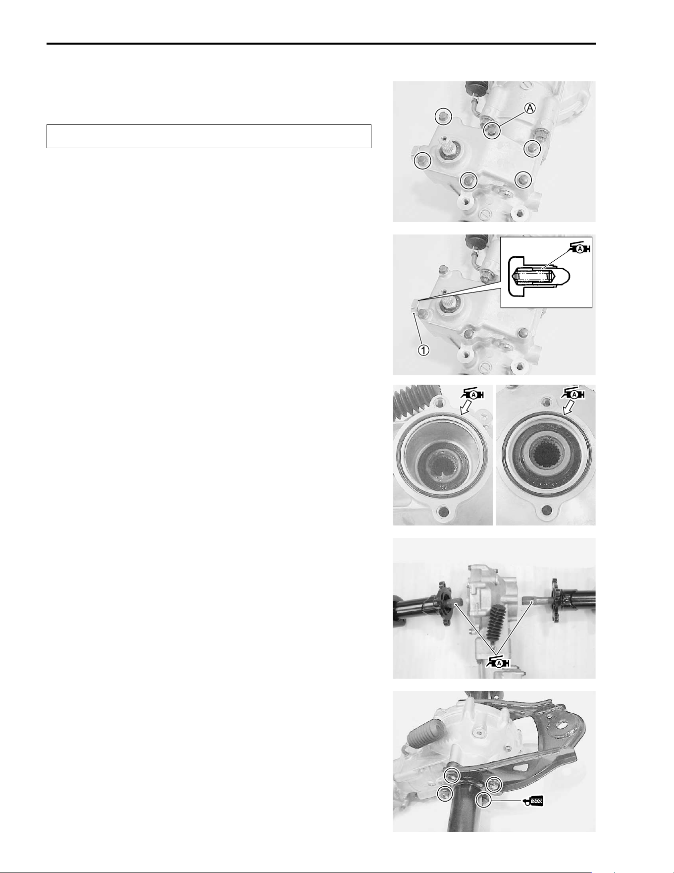
4-36 DRIVE TRAIN
• Install the new seal washer to the cover bolt
A.
"
• Tighten the cover bolts to the specified torque in a crisscross
pattern.
( Parking cam cover bolt: 10 N·m (1.0 kgf-m, 7.3 lb-ft)
• Apply the grease to the pin and install the parking cam stop-
per
1.
• Tighten the parking cam stopper
1 to the specified torque.
( Parking cam stopper: 23 N·m (2.3 kgf-m, 16.5 lb-ft)
$ 99000-25030: SUZUKI SUPER GREASE “A” (USA)
99000-25010: SUZUKI SUPER GREASE “A” (Others)
REAR DRIVE INSTALLATION
Install the rear drive in the reverse order of removal. Pay atten-
tion to the following points:
• Coat the new O-rings with grease and install them into the
grooves in the gear case and cover.
$ 99000-25030: SUZUKI SUPER GREASE “A” (USA)
99000-25010: SUZUKI SUPER GREASE “A” (Others)
• Apply grease to the splines of the axle and rear drive shaft
splines too.
$ 99000-25030: SUZUKI SUPER GREASE “A” (USA)
99000-25010: SUZUKI SUPER GREASE “A” (Others)
• Apply THREAD LOCK SUPER “1303” to the axle housing
bolts and tighten them to the specified torque.
) 99000-32030: THREAD LOCK SUPER “1303”
( Axle housing bolt: 55 N·m (5.5 kgf-m, 40 lb-ft)
Replace the seal washer with a new one.
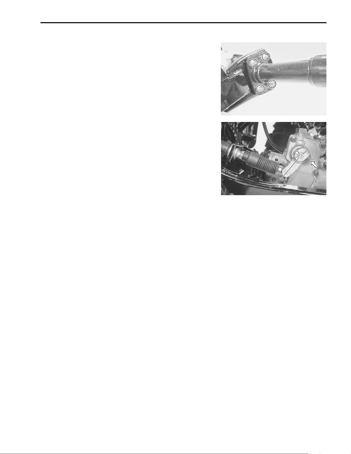
DRIVE TRAIN 4-37
• Install the rear drive gear case under cover.
• Tighten the axle housing mounting bolts to the specified
torque.
( Axle housing mounting bolt:
60 N·m (6.0 kgf-m, 43.5 lb-ft)
• When installing the parking cam lever, align the punched
marks on the shaft and lever.
• Make sure that the parking cam lever is in “P” position.
• Tighten the lever bolt to the specified torque.
( Parking cam lever bolt: 10 N·m (1.0 kgf-m, 7.3 lb-ft)
• Adjust the cable play. (!7-83)
• Pour the specified hypoid gear oil (SAE #90) in through the
filler hole. (!2-11)
• Install the rear brake caliper. (!7-51)
• Install the rear wheels. (!7-11)
P
P
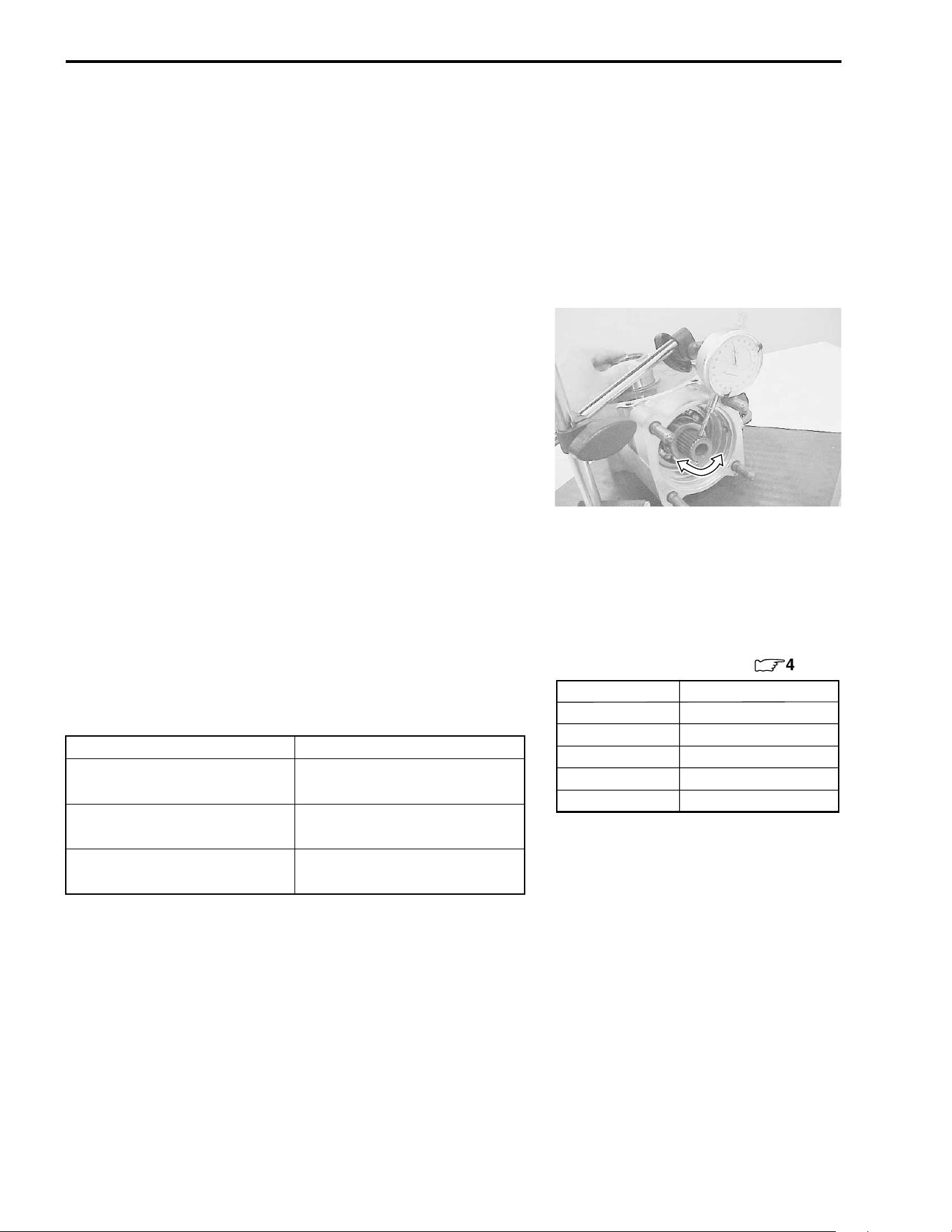
4-38 DRIVE TRAIN
SHIM ADJUSTMENT
BACKLASH
• Install the pinion gear assembly, removed shim(s) and new
bearing locknut. (!4-32)
• Tighten the bearing locknut to the specified torque. (!4-32)
NOTE:
At this time, it is not necessary to stake the bearing locknut.
(!4-32)
• Install the removed left side shim(s) and ring gear. (!4-33)
• Measure the backlash using the dial gauge, as shown. Take
backlash readings at several places while turning the pinion
gear shaft in each direction and securely holding the ring
gear. If the backlash is not within specification, the shim must
be changed and the backlash should be re-checked until cor-
rect. Refer to the chart at the right for the appropriate shim
thickness.
* Backlash
Standard: 0.02 – 0.06 mm (0.0008 – 0.0024 in)
........... Without gear case cover
specification
0.08 – 0.13 mm (0.0031 – 0.0051 in)
........... Gear case cover assembled
specification
NOTE:
Adjust the backlash by referring to the chart at the right and
using the thickness of the removed shims as a guide.
0
Backlash Shim adjustment
Under 0.02 mm
(0.0008 in)
Increase shim thickness
0.02 – 0.06 mm
(0.0008 – 0.0024 in)
Correct
Over 0.06 mm
(0.0024 in)
Decrease shim thickness
Part No.
Shim thickness
For left side of ring gear (
:
4-40)
27326-09F70-030 0.30 mm (0.0118 in)
27326-09F70-035 0.35 mm (0.0138 in)
27326-09F70-040 0.40 mm (0.0157 in)
27326-09F70-050 0.50 mm (0.0197 in)
27326-09F70-060 0.60 mm (0.0236 in)
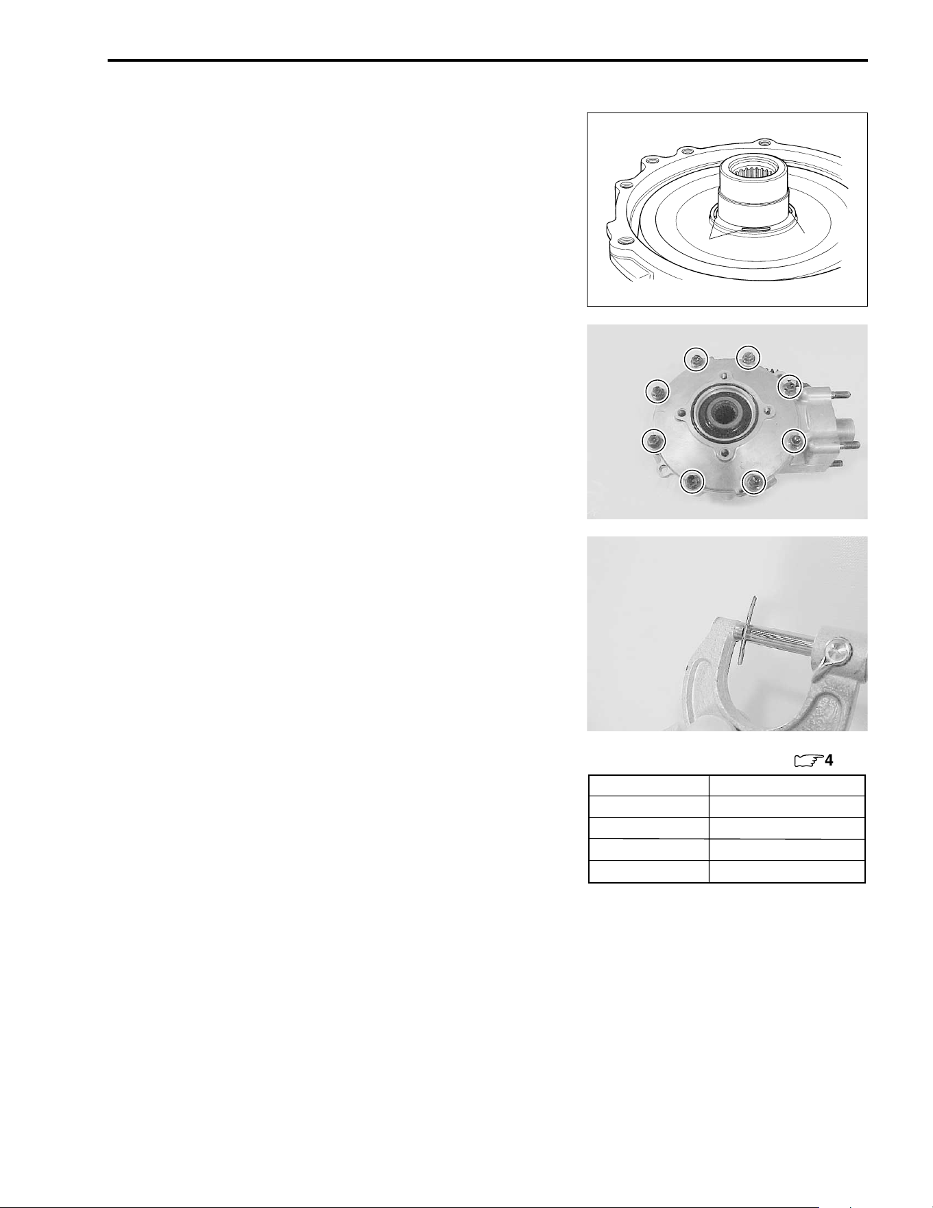
DRIVE TRAIN 4-39
RIGHT SIDE SHIM SELECTION
• After the backlash has been checked or adjusted, put a few
pieces of solder (O.D.: 1.2 – 1.5 mm × L: 6 mm) on the ring
gear back side, as shown.
NOTE:
* Do not install the right side shim(s) at this time.
* Apply a small quantity of grease to the solders to prevent them
from falling.
• Install the gear case cover and tighten its bolts to the speci-
fied torque in a crisscross pattern. (!4-33)
NOTE:
* Do not install the new O-ring to the gear case cover.
* Do not apply a thread lock to the case cover bolts.
( Gear case cover bolt: 23 N·m (2.3 kgf-m, 16.5 lb-ft)
• Remove the gear case cover. (!4-26)
• Measure the thickness of compressed solder with the
micrometer.
# 09900-20205: Micrometer
• Select the proper size of shim(s) from the right chart, accord-
ing as the compressed solder thickness.
• After selecting the proper size of shim(s), install it on the ring
gear back side.
Solder
Solder
Part No.
Shim thickness
For right side of ring gear (
:
4-40)
27326-18A00-035 0.35 mm (0.0138 in)
27326-18A00-040 0.40 mm (0.0157 in)
27326-18A00-050 0.50 mm (0.0197 in)
27326-18A00-060 0.60 mm (0.0236 in)
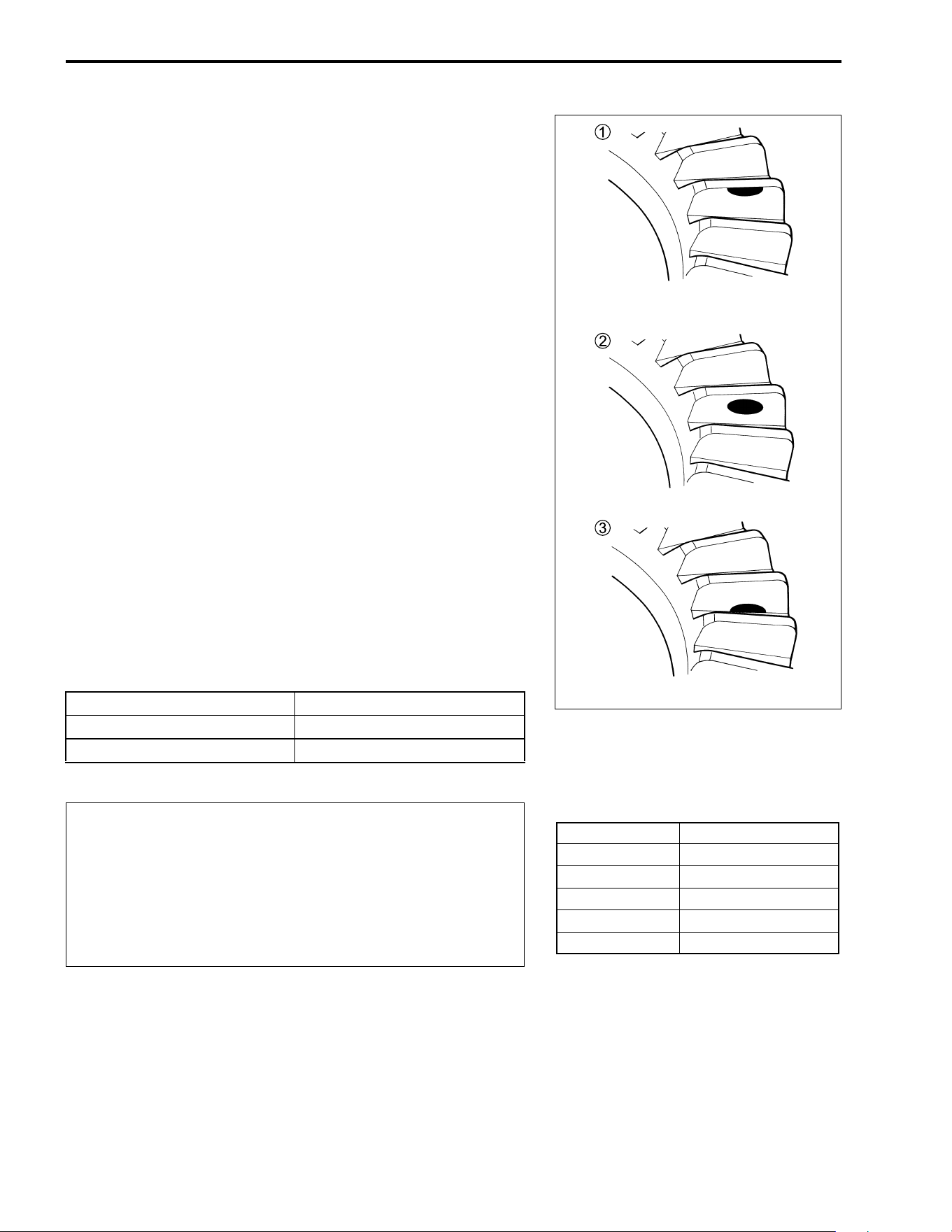
4-40 DRIVE TRAIN
TOOTH CONTACT
After backlash adjustment and right shim selection are carried
out, the tooth contact must be checked. Pay attention to the fol-
lowing procedures:
• Remove the ring gear.
• Clean and degrease several teeth on the ring gear and pinion
gear, and then apply a coating of machinist’s layout dye or
paste to several teeth of the pinion gear.
• Install the ring gear with the shims in place.
• Install the gear case cover, and then tighten the bolts to the
specified torque in a crisscross pattern. (!4-33)
( Gear case cover bolt: 23 N·m (2.3 kgf-m, 16.5 lb-ft)
NOTE:
At this time, it is not necessary to install the gear case cover’s O-
ring.
• Rotate the gear several turns in each direction. This will pro-
vide a contact pattern on the coated teeth of the gear.
• Remove the ring gear and compare the coated teeth to the
examples shown in
1,
2 and
3.
• If tooth contact is found to be correct (example
2), go to the
FINAL ASSEMBLY sub-section on p.4-33 to complete instal-
lation.
• If tooth contact is found to be incorrect (examples
1 and
3),
the shim between the pinion gear bearing and gear case must
be changed and the tooth contact re-checked until correct.
"
Tooth contact Shim adjustment
Contact at tooth top
1 Decrease shim thickness
Contact at tooth root
3 Increase shim thickness
Make sure to check the backlash and shim thickness
after the tooth contact has been adjusted, since it may
have changed. Adjust the tooth contact and backlash
until they are both within specification. If the correct
tooth contact cannot be maintained when adjusting
the backlash, replace the pinion gear and ring gear as
a set.
Incorrect (Contact at tooth top)
Incorrect (Contact at tooth root)
Correct
Part No.
Shim thickness
For pinion gear
27445-24A01-030 0.30 mm (0.0118 in)
27445-24A01-035 0.35 mm (0.0138 in)
27445-24A01-040 0.40 mm (0.0157 in)
27445-24A01-050 0.50 mm (0.0197 in)
27445-24A01-060 0.60 mm (0.0236 in)
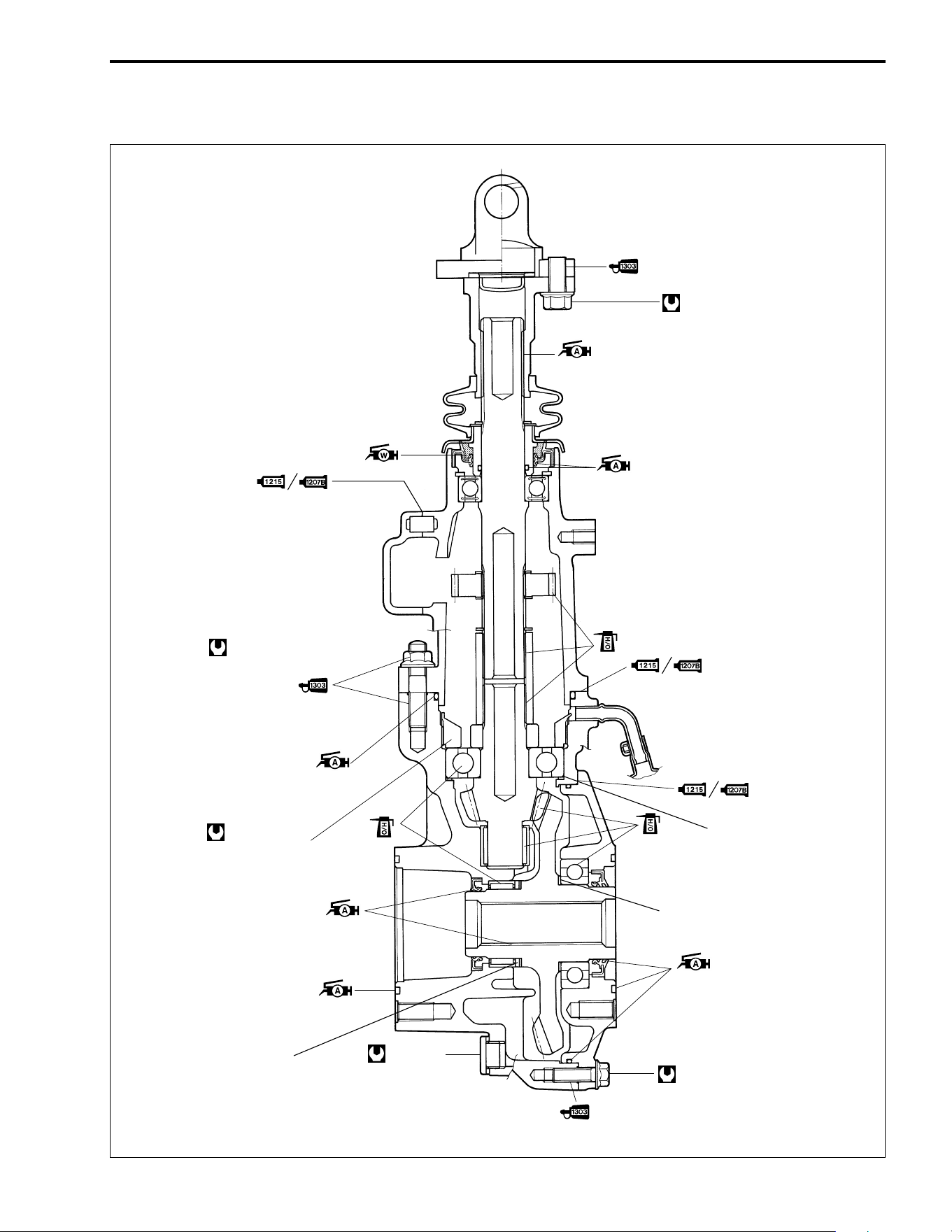
DRIVE TRAIN 4-41
REASSEMBLY INFORMATION
30 N
.
m
(3.0 kgf-m, 21.5 lb-ft)
110 N
.
m
(11.0 kgf-m, 79.5 lb-ft)
33 N
.
m
3.3 kgf-m
24.0 lb-ft
( )
23 N
.
m
2.3 kgf-m
16.5 lb-ft
( )
Mating surfaces
Mating surfaces
Left side of
ring gear shim(s)
Right side of
ring gear shim(s)
Pinion gear shim(s)
5 – 7 gram
4 – 5 gram
23 N
.
m
(2.3 kgf-m, 16.5 lb-ft)
Mating surfaces
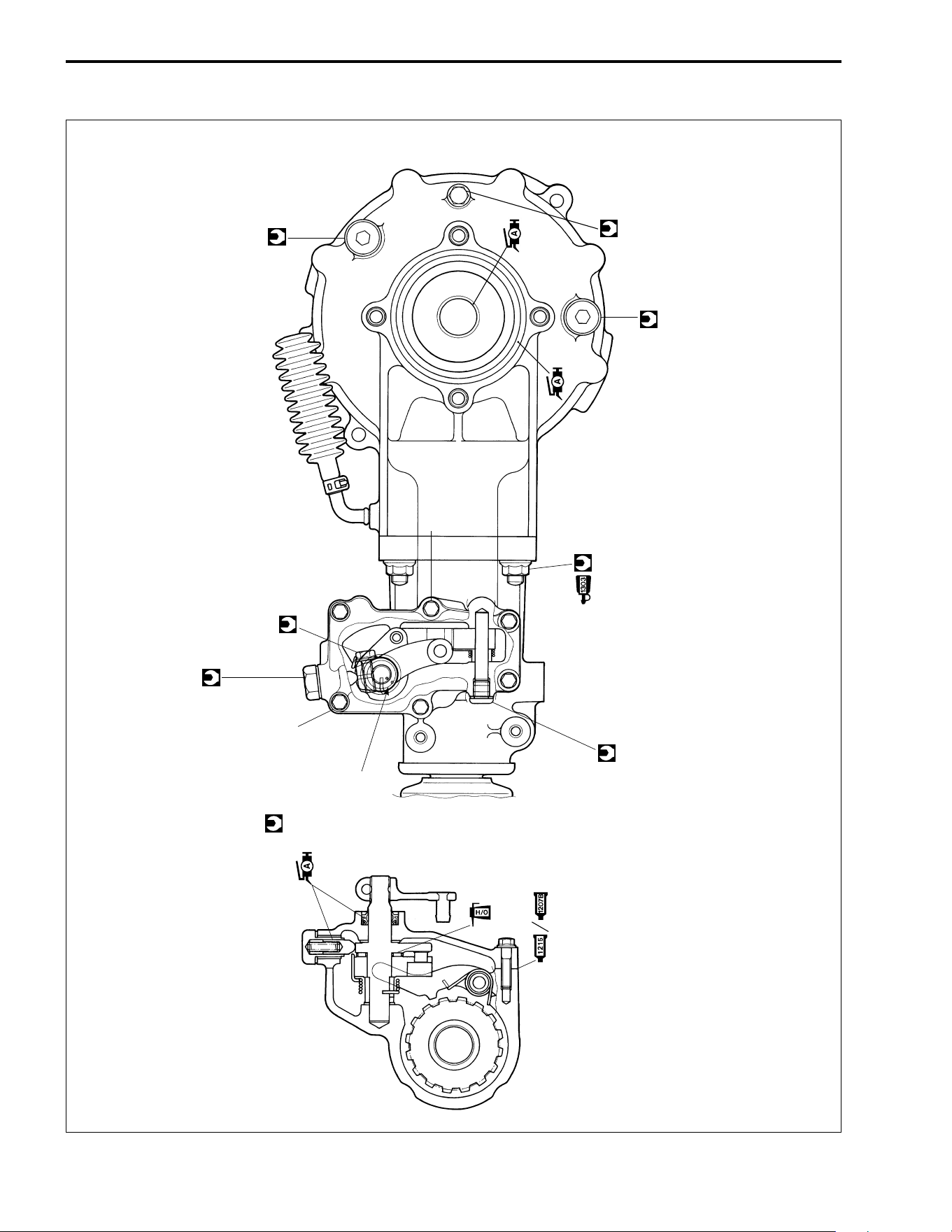
4-42 DRIVE TRAIN
Mating surfaces
Align the punched
marks
10 N
.
m
(1.0 kgf-m, 7.3 lb-ft)
15 N
.
m
(1.5 kgf-m, 11.0 lb-ft)
23 N
.
m
(2.3 kgf-m, 16.5 lb-ft)
10 N
.
m
(1.0 kgf-m, 7.3 lb-ft)
23 N
.
m
(2.3 kgf-m, 16.5 lb-ft)
33 N
.
m
(3.3 kgf-m, 24.0 lb-ft)
With
seal washer
20 N
.
m
2.0 kgf-m
14.5 lb-ft
( )
33 N
.
m
3.3 kgf-m
24.0 lb-ft
( )

5
FUEL SYSTEM 5-1
CONTENTS
FUEL SYSTEM
FUEL TANK ........................................................................................ 5- 2
CONSTRUCTION .........................................................................5- 2
FUEL LINE INSPECTION ............................................................5- 3
REMOVAL .................................................................................... 5- 3
REMOUNTING .............................................................................5- 3
FUEL VALVE ......................................................................................5- 4
REMOVAL AND INSPECTION ....................................................5- 4
FUEL STRAINER ......................................................................... 5- 4
REMOUNTING .............................................................................5- 4
FUEL LEVEL GAUGE ........................................................................5- 5
REMOVAL .................................................................................... 5- 5
INSPECTION ................................................................................5- 5
REMOUNTING .............................................................................5- 5
CARBURETOR ................................................................................... 5- 6
CONSTRUCTION .........................................................................5- 6
SPECIFICATIONS .......................................................................5- 7
I.D. NO. LOCATION .....................................................................5- 7
REMOVAL .................................................................................... 5- 8
DISASSEMBLY ............................................................................5- 9
CLEANING ...................................................................................5-12
INSPECTION ................................................................................ 5-12
REASSEMBLY .............................................................................5-13
REMOUNTING .............................................................................5-14
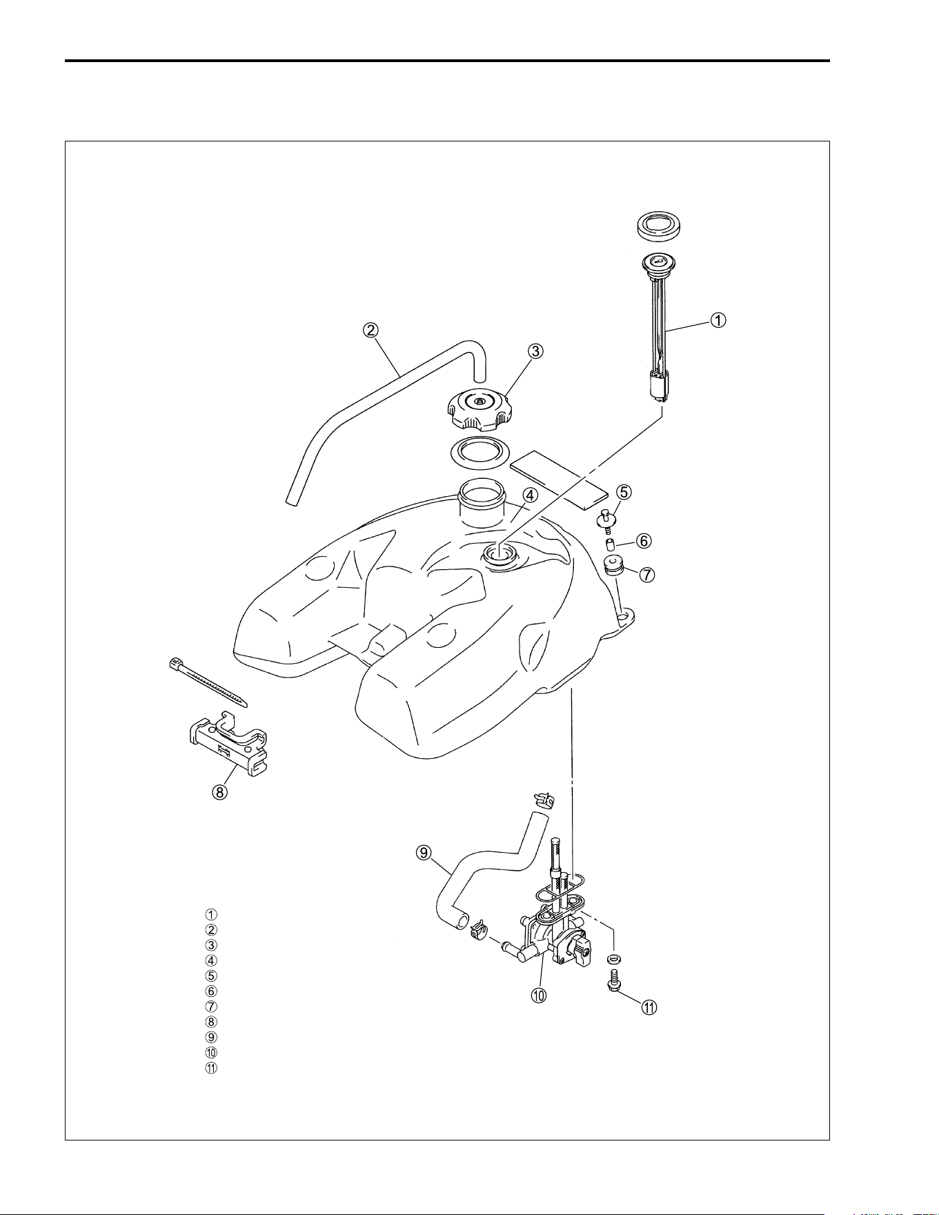
5-2 FUEL SYSTEM
FUEL TANK
CONSTRUCTION
Fuel level gauge
Breather hose
Fuel tank cap
Fuel tank assy
Bolt
Spacer
Cushion rear
Cushion front
Fuel hose
Fuel valve
Bolt
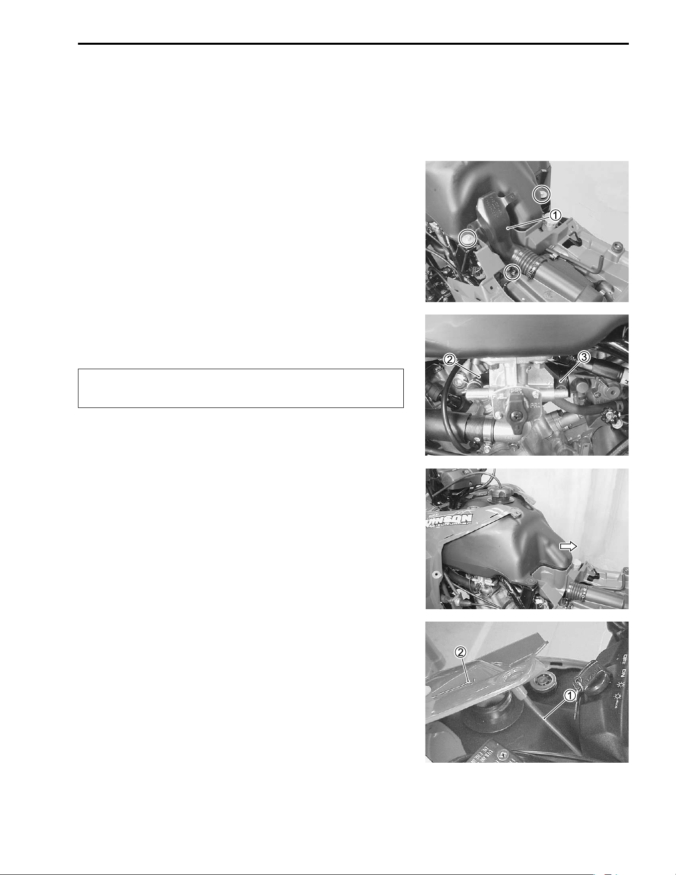
FUEL SYSTEM 5-3
FUEL LINE INSPECTION
Inspect the fuel lines, fuel tank, and fuel tank cap for damage
and fuel leakage. If any damages are found, replace the defec-
tive parts with new ones.
REMOVAL
• Remove the seat, fuel tank covers and fuel tank top cover.
(!7-5)
• Remove the air cleaner duct
1.
• Remove the fuel tank mounting bolts.
• Turn the fuel valve to the “ON” position.
• Disconnect the fuel hose
2 and vacuum hose
3.
"
• Remove the fuel tank.
• Drain the fuel completely.
REMOUNTING
Remount the fuel tank in the reverse order of removal.
Pay attention to the following points:
• Route the fuel hose and breather hoses properly. (!9-17)
• Connect the fuel tank breather hose
1 to the fuel tank top
cover
2.
Gasoline is highly flammable and explosive.
Keep heat, sparks and flames away from gasoline.
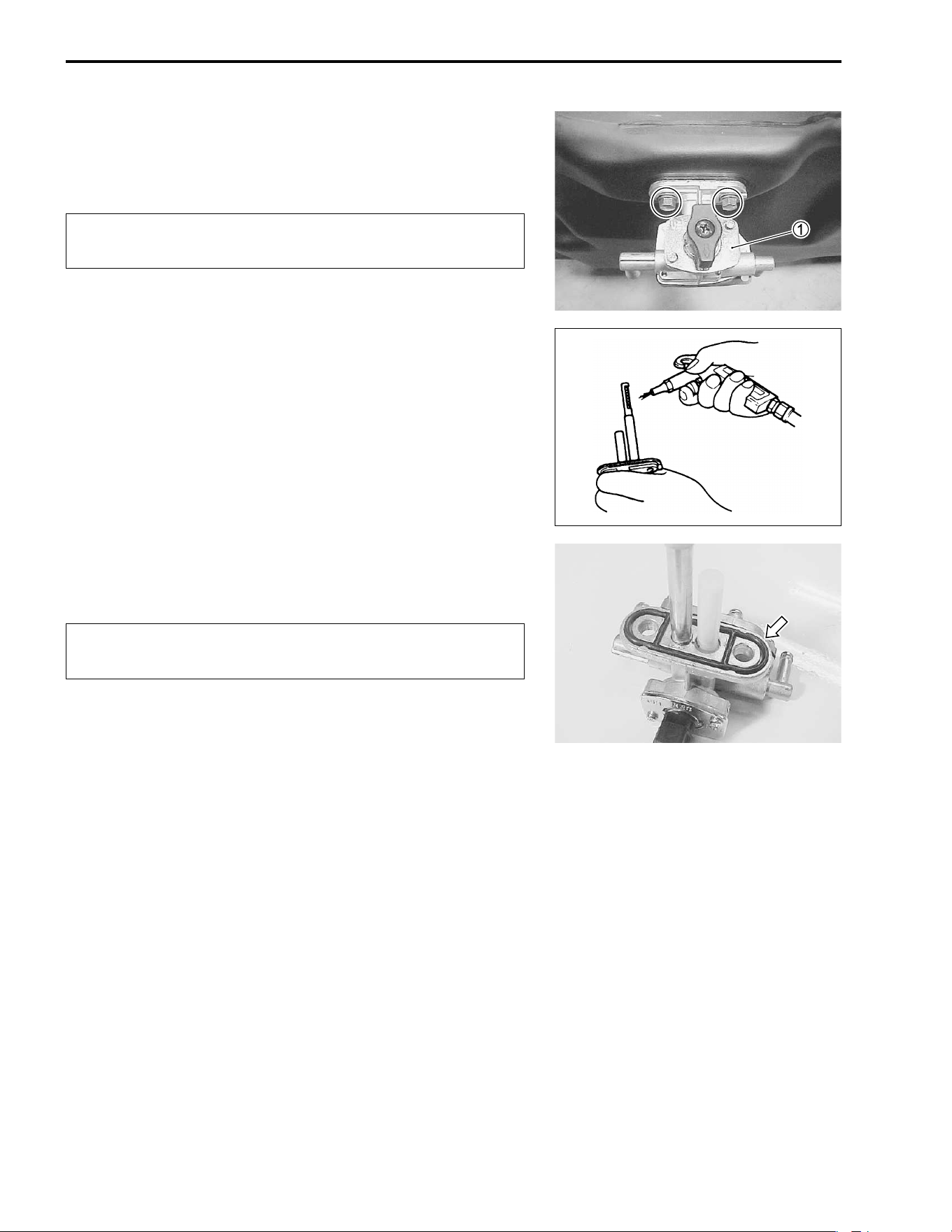
5-4 FUEL SYSTEM
FUEL VALVE
REMOVAL AND INSPECTION
• Remove the fuel tank. (!5-3)
• Remove the fuel valve
1.
"
FUEL STRAINER
If the fuel strainer is dirty with sediment or rust, fuel will not flow
smoothly and loss in engine power may result. Clean the fuel
strainer with compressed air.
REMOUNTING
Remount the fuel valve in the reverse order of removal.
"
Gasoline is highly flammable and explosive.
Keep heat, sparks and flames away from gasoline.
Replace the removed gasket with a new one to prevent
fuel leakage.
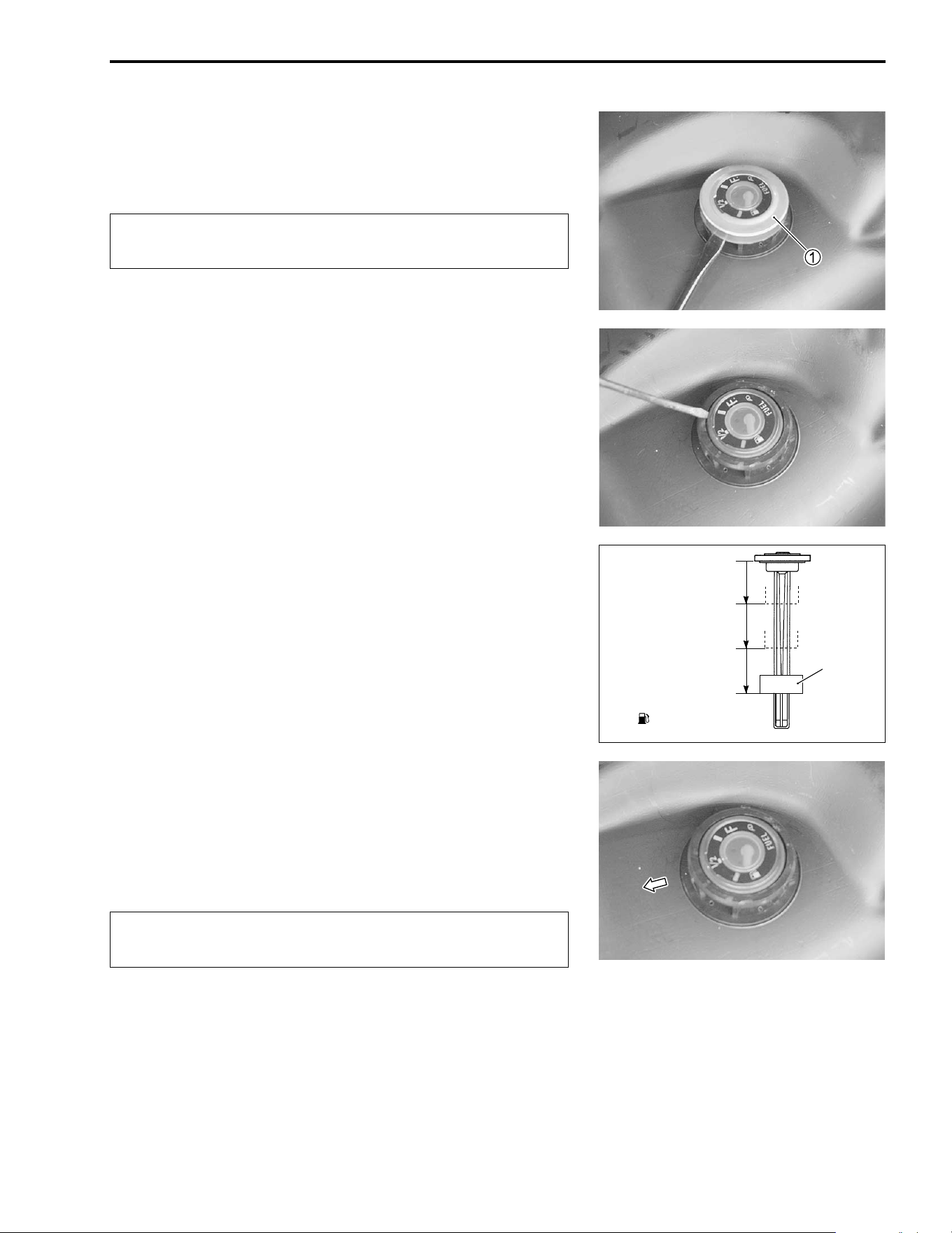
FUEL SYSTEM 5-5
FUEL LEVEL GAUGE
REMOVAL
• Remove the fuel tank top cover. (!7-5)
• Remove the fuel level gauge cap
1.
"
• Remove the fuel level gauge.
INSPECTION
Inspect the float of the fuel gauge assembly moves smoothly.
Inspect that the needle moves correctly as the float of the fuel
gauge assembly moves up and down as shown in the illustra-
tion.
REMOUNTING
• Remount the fuel level gauge in the reverse order of removal.
NOTE:
When installing the fuel level gauge, “½” indication must be
faced forward.
#
* Gasoline is highly flammable and explosive.
* Keep heat, sparks and flames away from gasoline.
Approx. 83 mm
“F”
Approx. 113 mm
“1/2”
Approx. 142 mm
“ ”
Float
Replace the removed fuel level gauge cap with a new
one.
FWDFWD
5-6 FUEL SYSTEM
CARBURETOR
CONSTRUCTION
Cover assy
Spring retainer
Jet Needle
Diaphragm assy
Spring
Hose
Cover
Starter plunger
Spring
Guide holder
Cap
Diaphragm assy
Spring
Cover
Float chamber
Slow jet
Hose
O-ring
Needle jet holder
Main jet
Needle valve
Float pin
Throttele stop screw
Pilot screw
Float
Gasket
Starter jet
FUEL SYSTEM 5-7
SPECIFICATIONS
E-03: USA E-28: Canada E-33: California (USA)
I.D. NO. LOCATION
Carburetor has an I.D. number
1 punched on its body.
ITEM
SPECIFICATION
E-03, 28 E-33
Carburetor type KEIHIN CVK36 ←
Bore size 36 mm ←
I.D. No. 03GF 03GG
Idle r/min 1 300 ± 100 r/min ←
Float height 17.0 ± 1.0 mm
(0.67 ± 0.04 in)
←
Main jet (M.J.) #128 ←
Jet needle (J.N.) NBAY ←
Needle jet (N.J.) #6 ←
Slow jet (S.J.) #35 ←
Pilot screw (P.S.)
1·3/8 turns back PRE-SET
Throttle cable play
(pulling cable)
3 – 5 mm
(0.12 – 0.20 in)
←
Starter (enricher) plunger cable play 0.5 – 1.0 mm
(0.02 – 0.04 in)
←
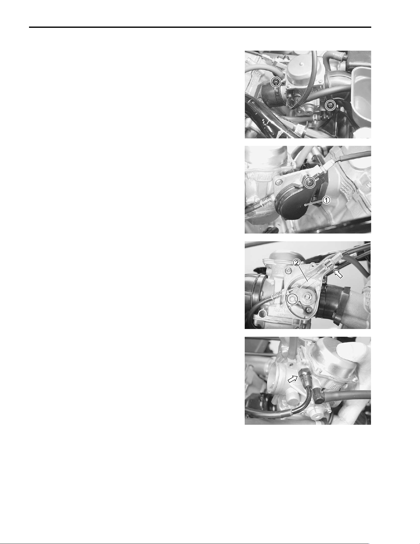
5-8 FUEL SYSTEM
REMOVAL
• Remove the fuel tank. (!5-3)
• Loosen the carburetor clamp screws.
• Remove the carburetor side cap
1.
• Disconnect the throttle cable
2.
• Remove the carburetor.
• Disconnect the starter cable.
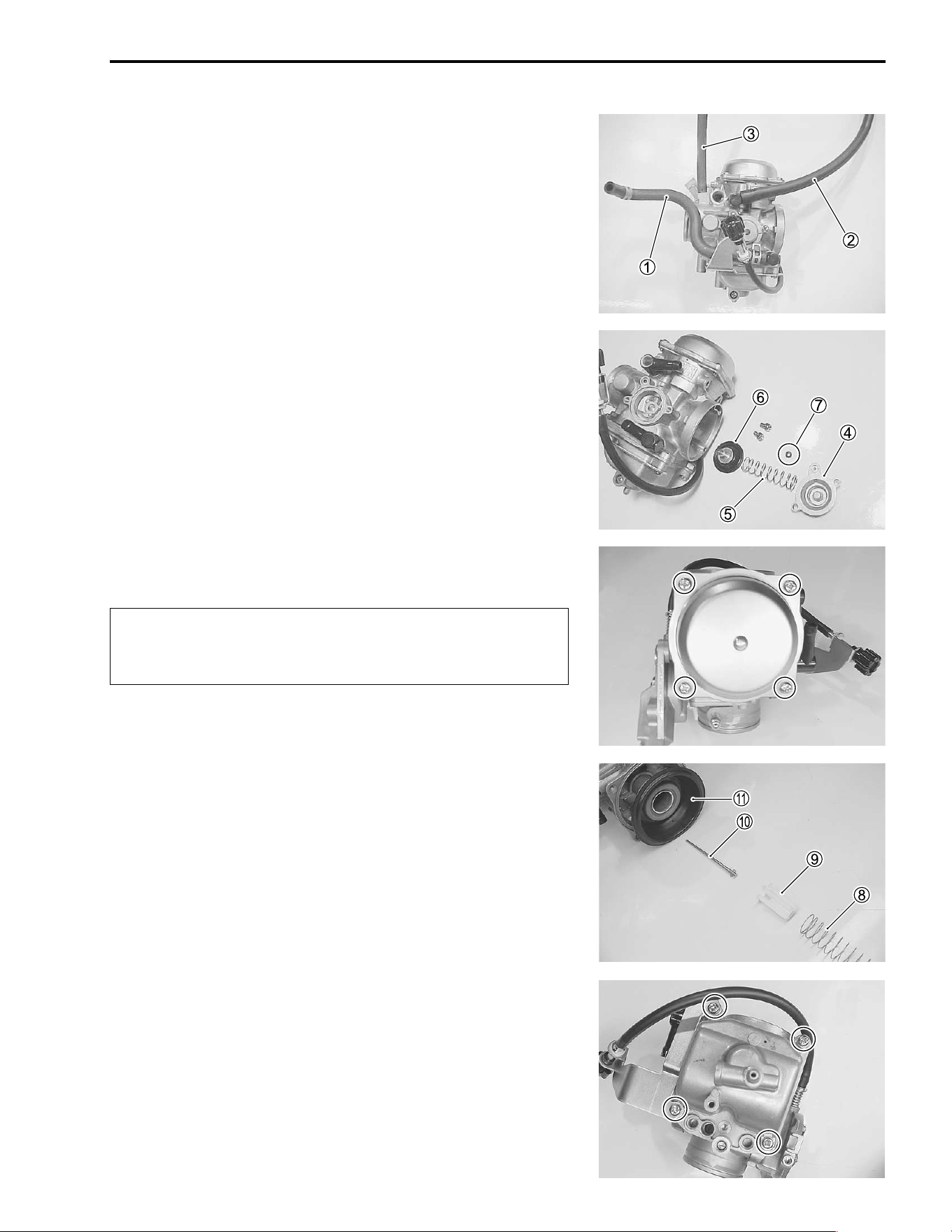
FUEL SYSTEM 5-9
DISASSEMBLY
• Remove the fuel hose
1, air vent hoses
2 and vacuum hose
3.
• Remove the coasting enrichment valve cover
4, spring
5,
coasting enrichment valve
6 and O-ring
7.
• Remove the top cap.
#
• Remove the spring
8, spring retainer
9, jet needle
0 and
diaphragm
A.
• Remove the float chamber.
Do not use compressed air on the carburetor body
before removing the diaphragm; this may damage the
diaphragm.
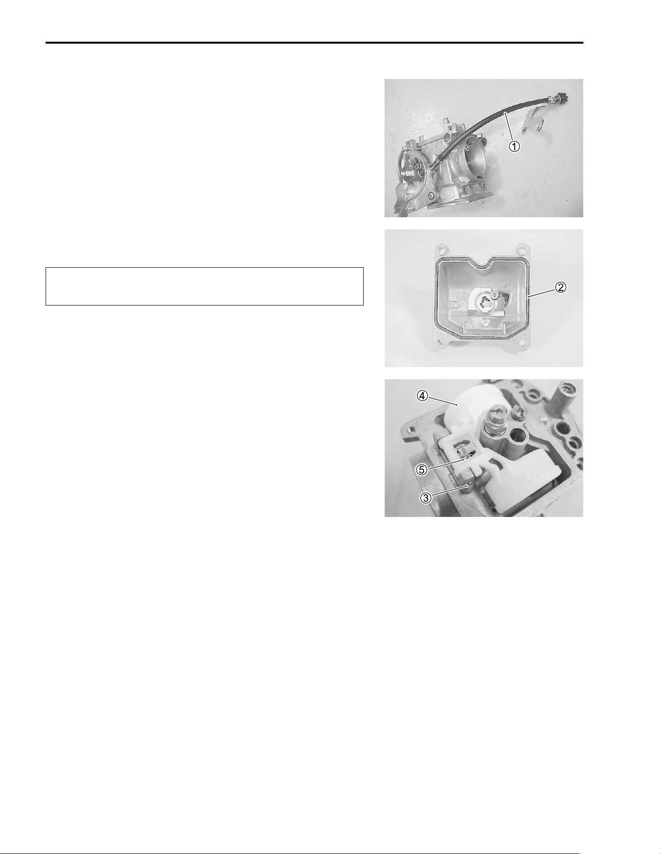
5-10 FUEL SYSTEM
• Remove the throttle stop screw
1.
• Remove the O-ring
2.
#
• Remove the float pin
3, float
4 and needle valve
5.
Replace the removed O-ring with a new one to prevent
fuel leakage.
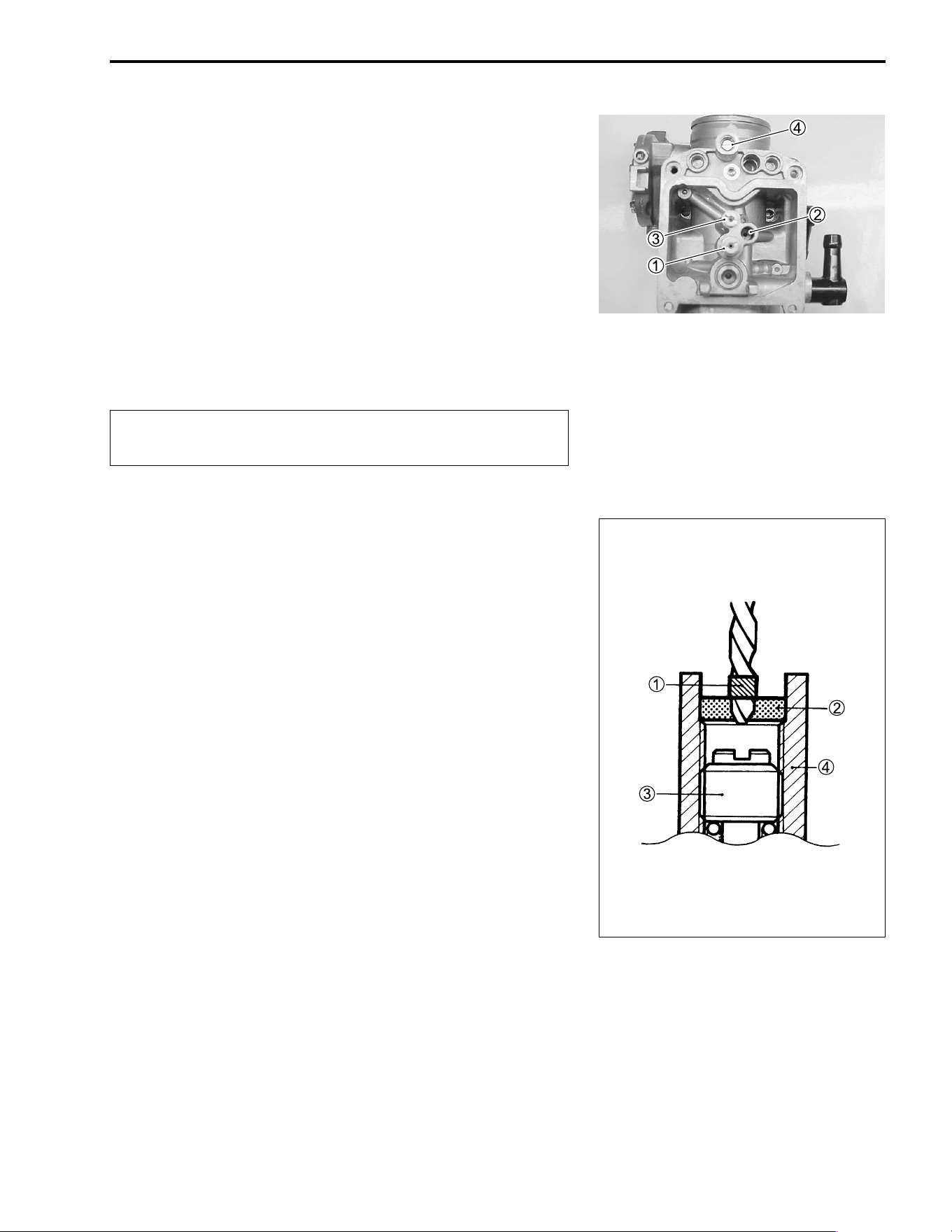
FUEL SYSTEM 5-11
• Remove the following parts.
1 Main jet and needle jet holder
2 Slow jet
3 Starter jet
4 Pilot screw
NOTE:
Before removing the pilot screw
4, its setting must be deter-
mined. Slowly turn the pilot screw clockwise and count the num-
ber of turns until it is lightly seated. Make a note of how many
turns were made.
When reassembling the pilot screw, you will want to set it to its
original position.
#
PILOT SCREW REMOVAL (For E-33)
Because harsh cleaning solvents can damage the O-ring seals
in the pilot system, the pilot system components should be
removed before cleaning.
• Use a 1/8" size drill bit with a drill-stop to remove the pilot
screw plug. Set the drill-stop 4 mm (0.16 in) from the end of
the bit to prevent drilling into the pilot screw. Carefully drill
through the plug.
• Thread a self-tapping sheet metal screw into the plug. Pull on
the screw head with pliers to remove the plug. Carefully clean
any metal shavings from the area.
• Slowly turn the pilot screw clockwise and count the number of
turns until the screw is lightly seated. Make a note of how
many turns were made so the screw can be reset correctly
after cleaning.
• Remove the pilot screw along with the spring, washer and O-
ring.
• After cleaning, install the pilot screw to the original setting by
turning the screw in until it lightly seats, and then backing it
out the same number of turns counted during disassembly.
• Install a new plug by tapping it into place with a punch.
1 Drill-stop
2 Plug
3 Pilot screw
4 Carburetor body
Do not use wire to clean the passageways, valve seat
and jets. Used compressed air only.
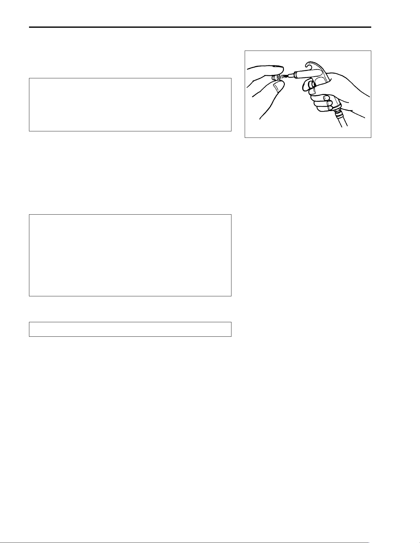
5-12 FUEL SYSTEM
CLEANING
"
• Clean all jets with a spray-type carburetor cleaner and dry
them using compressed air.
• Clean all circuits of the carburetor thoroughly – not just the
perceived problem area. Clean the circuits in the carburetor
body with a spray-type cleaner. If necessary, soak each cir-
cuit in a dip-type cleaning solution to loosen dirt and varnish.
Dry the carburetor body using compressed air.
#
• After cleaning, reassemble the carburetor with new O-rings.
#
INSPECTION
Check the following items for any damage or clogging. If any
damages are found, replace the damaged parts with new ones.
* Slow jet * Valve seat
* Main jet * Piston valve
* Main air jet * Starter jet
* Slow air jet * O-ring
* Needle jet air bleeding hole * Throttle valve
* Float * Diaphragm
* Needle valve * Pilot outlet and by-pass ports
* Jet needle
Some carburetor cleaning chemicals, especially dip-
type soaking solutions, are very corrosive and must
be handled carefully. Always follow the chemical man-
ufacturer’s instructions on proper use, handling and
storage.
Do not use a wire to clean the jets or passageways. If
wire is used, the jets and passageways may become
damaged. If the components cannot be cleaned with a
spray-type cleaner it may be necessary to soak the
components in a dip-type cleaning solution. Always
follow the chemical manufacturer’s instructions for
proper use and cleaning of the carburetor compo-
nents.
Replace the removed O-rings with new ones.
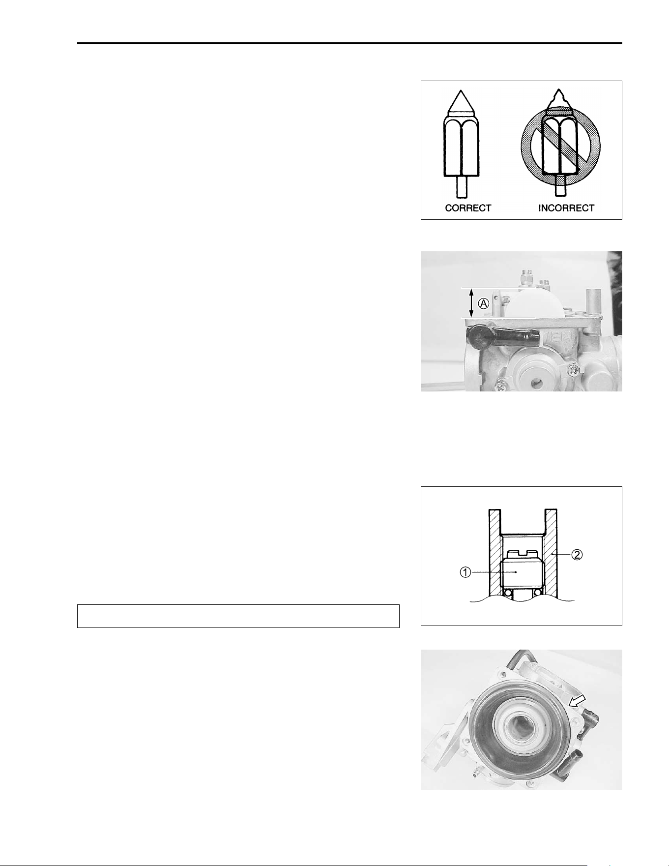
FUEL SYSTEM 5-13
NEEDLE VALVE INSPECTION
If foreign matter is caught between the valve seat and the nee-
dle valve, the gasoline will continue flowing and overflow. If the
valve seat and needle valve are worn beyond the permissible
limits, similar trouble will occur. Conversely, if the needle valve
sticks, the gasoline will not flow into the float chamber. Clean the
float chamber and float parts with gasoline. If the needle valve is
worn as shown, replace and the valve seat with a new one.
Clean the fuel passage of the mixing chamber using com-
pressed air.
FLOAT HEIGHT ADJUSTMENT
To check the float height, turn the carburetor upside down.
Measure the float height
A while the float arm is just contacting
the needle valve using vernier calipers.
Bend the tongue as necessary to bring the float height
A to the
specified level.
$ 09900-20101: Vernier calipers
% Float height
A
AA
A: 17.0 ± 1.0 mm (0.67 ± 0.04 in)
REASSEMBLY
Reassemble the carburetor in the reverse order of disassembly.
Pay attention to the following points:
PILOT SCREW
• After cleaning, install the pilot screw
1 to the original setting
by turning the screw in until it lightly seats, and then backing it
out the same number of turns counted during disassembly.
1 Pilot screw
2 Carburetor body
#
• Install the diaphragm.
NOTE:
When installing the diaphragm, make sure the tab of the dia-
phragm is aligned with the concave section of the carburetor
body’s rim.
Replace the removed O-ring with a new one.
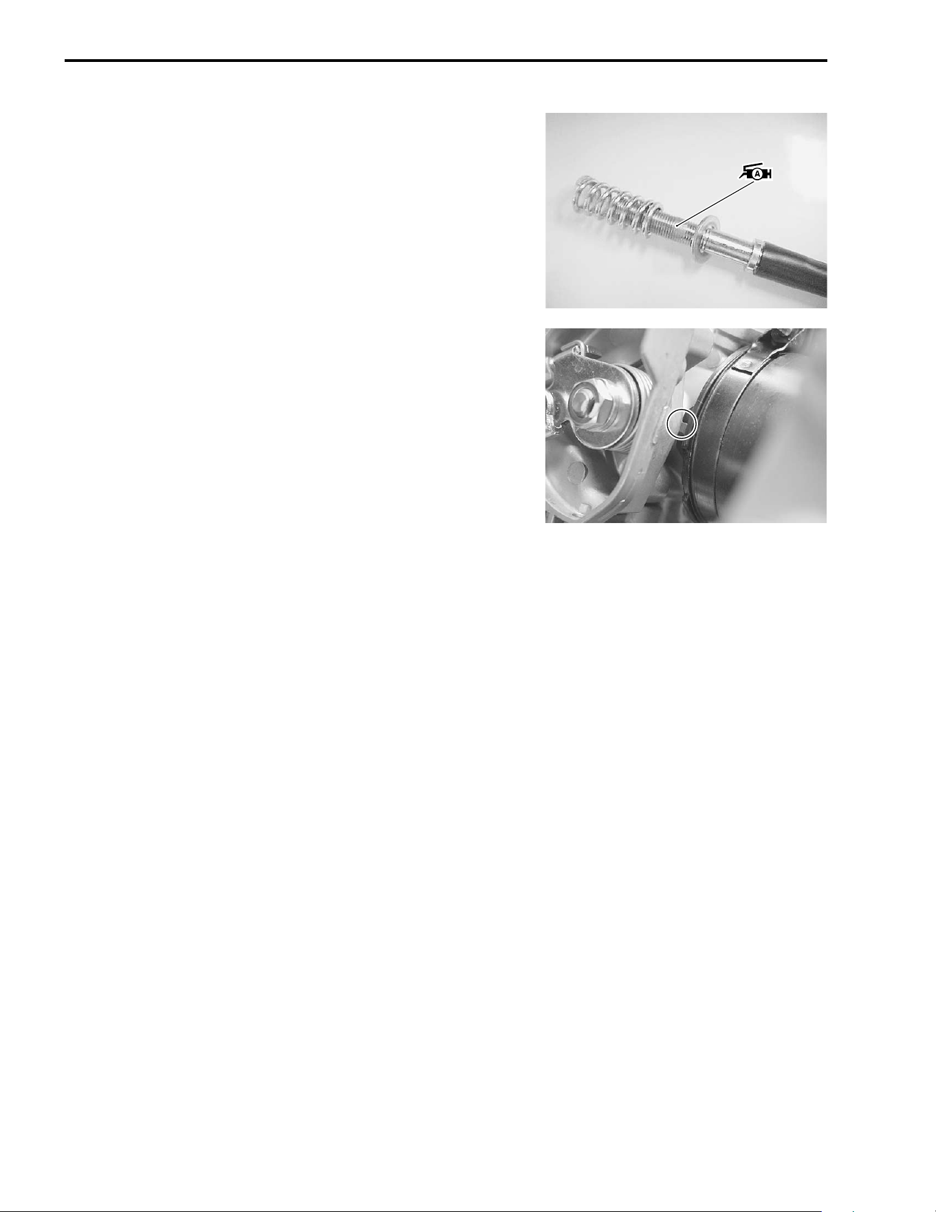
5-14 FUEL SYSTEM
THROTTLE STOP SCREW
• Apply the grease to thread part of the throttle stop screw, then
install the throttle stop screw to the carburetor.
& 99000-25030: SUZUKI SUPER GREASE “A” (USA)
99000-25010: SUZUKI SUPER GREASE “A” (Others)
REMOUNTING
Remount the carburetor assembly in the reverse order of
removal. Pay attention to the following points:
• Align the lug on the carburetor with the intake pipe’s cutout.
After the carburetor assembly has been remounted onto the
engine perform the following adjustments:
* Throttle cable play ........................................ !2-8
* Engine idle speed ......................................... !2-8

6
COOLING AND LUBRICATION SYSTEM 6-1
CONTENTS
COOLING AND LUBRICATION SYSTEM
ENGINE COOLANT ..............................................................................6- 2
COOLING CIRCUIT ..............................................................................6- 3
COOLING CIRCUIT INSPECTION ..............................................6- 3
RADIATOR AND HOSES .....................................................................6- 4
RADIATOR REMOVAL ................................................................6- 4
RADIATOR REMOUNTING .........................................................6- 4
RADIATOR RESERVOIR TANK REMOVAL AND
REMOUNTING .............................................................................6- 4
RADIATOR CAP INSPECTION ...................................................6- 5
RADIATOR INSPECTION AND CLEANING ...............................6- 5
RADIATOR HOSE INSPECTION .................................................6- 6
COOLING FAN .....................................................................................6- 7
REMOVAL ....................................................................................6- 7
INSPECTION ................................................................................6- 7
INSTALLATION ...........................................................................6- 8
COOLING FAN THERMO-SWITCH .....................................................6- 9
REMOVAL ....................................................................................6- 9
INSPECTION ................................................................................6- 9
INSTALLATION ...........................................................................6- 9
ENGINE COOLANT TEMPERATURE SWITCH ..................................6-10
REMOVAL ....................................................................................6-10
INSPECTION ................................................................................6-10
INSTALLATION ...........................................................................6-10
THERMOSTAT .....................................................................................6-11
REMOVAL ....................................................................................6-11
INSPECTION ................................................................................6-11
INSTALLATION ...........................................................................6-11
WATER PUMP ......................................................................................6-13
REMOVAL ....................................................................................6-13
INSPECTION ................................................................................6-13
DISASSEMBLY ............................................................................6-14
REASSEMBLY AND INSTALLATION .........................................6-15
LUBRICATION SYSTEM ......................................................................6-17
OIL PRESSURE ...........................................................................6-17
OIL FILTER ..................................................................................6-17
OIL PRESSURE REGULATOR ...................................................6-17
OIL SUMP FILTER .......................................................................6-17
OIL PUMP ....................................................................................6-17
ENGINE LUBRICATION SYSTEM CHART .................................6-18
ENGINE LUBRICATION SYSTEM ..............................................6-19
6-2 COOLING AND LUBRICATION SYSTEM
ENGINE COOLANT
At the time of manufacture, the cooling system is filled with a
50:50 mixture of distilled water and ethylene glycol anti-freeze.
This 50:50 mixture will provide the optimum corrosion protection
and excellent heat protection, and will protect the cooling system
from freezing at temperatures above –31°C (–24°F).
If the vehicle is to be exposed to temperatures below –31°C
(–24°F), this mixing ratio should be increased up to 55% or
60% according to the figure.
!
50% Engine coolant including reserve tank capacity
"
* Use a high quality ethylene glycol base anti-freeze,
mixed with distilled water. Do not mix an alcohol
base anti-freeze and different brands of anti-freeze.
* Do not put in more than 60% anti-freeze or less than
50%. (Refer to Right figure.)
* Do not use a radiator anti-leak additive.
Anti-freeze 1 000 ml (2.1/1.8 US/lmp. pt)
Water 1 000 ml (2.1/1.8 US/lmp. pt)
Anti-freeze
density
Freezing point
50%
55%
60%
–30˚C (–24˚F)
–40˚C (–44˚F)
–55˚C (–67˚F)
20 40 60 80 100
Density (%)
0
–10
–20
–30
–40
–50
–60
–70
32
14
–4
–22
–40
–58
–76
–94
Freezing point
Fig.1 Engine coolant density-freezing
point curve.
(˚C)
(˚F)
0 10 20 30 40 50 60
Density (%)
150
140
130
120
110
100
Biling point
(˚C)
(˚F)
302
284
266
248
230
212
Engine coolant density-boiling
point curve.
Fig.2
(kgf/cm²)
1.5
0.9
0.5
0
Gauge pressure
* You can be injured by scalding fluid or steam if you open the radiator cap when the engine is
hot. After the engine cools, wrap a thick cloth around cap and carefully remove the cap by
turning it a quarter turn to allow pressure to escape and then turn the cap all the way off.
* The engine must be cool before servicing the cooling system.
* Coolant is harmful;
• If it comes in contact with skin or eyes, flush with water.
• If swallowed accidentally, induce vomiting and call physician immediately.
• Keep it away from children.
COOLING AND LUBRICATION SYSTEM 6-3
COOLING CIRCUIT
COOLING CIRCUIT INSPECTION
Before removing the radiator and draining the engine coolant,
inspect the cooling circuit for tightness.
• Remove the radiator cap lid.
• Remove the radiator cap
1 and connect the tester
2 to the
filler.
"
• Give a pressure of about 120 kPa (1.2 kgf/m², 17 psi) and see
if the system holds this pressure for 10 seconds.
• If the pressure should fall during this 10-second interval, it
means that there is a leaking point in the system. In such a
case, inspect the entire system and replace the leaking com-
ponent or part.
"
!
Do not remove the radiator cap when the engine is
hot.
WATER
PUMP
RADIATOR
COOLING
FAN THERMO
SWITCH
ENGINE COOLANT
TEMPERATURE
SWITCH
THERMOSTAT
CYLINDER HEAD
CYLINDER
RESERVOIR
TANK
When removing the radiator cap tester, put a rag on
the filler to prevent spouting of engine coolant.
Do not allow the pressure to exceed the radiator cap
release pressure, or the radiator can be damaged.
6-4 COOLING AND LUBRICATION SYSTEM
RADIATOR AND HOSES
RADIATOR REMOVAL
• Remove the front fender. (#7-6)
• Drain engine coolant by removing the drain plug.
• Disconnect the cooling fan motor lead wire coupler
1 and
cooling fan thermo-switch lead wire coupler
2.
• Disconnect the upper and lower radiator hoses.
• Disconnect the siphon hose from the radiator.
• Remove the two mounting bolts and radiator assembly.
RADIATOR REMOUNTING
• Install the radiator.
• Connect the radiator hoses. (#9-18)
• Connect the siphon hose, cooling fan thermo-switch lead wire
coupler and cooling fan motor lead wire coupler.
• Install the drain plug with a new sealing washer.
• Pour engine coolant. (#2-12)
• Install the front fender.
RADIATOR RESERVOIR TANK REMOVAL AND
REMOUNTING
• Remove the reservoir tank mounting bolts and disconnect the
siphon hose from the reservoir tank and drain engine coolant.
• Install the reservoir tank in the reverse order of removal.
• Fill the reservoir tank to the upper level line.
COOLING AND LUBRICATION SYSTEM 6-5
RADIATOR CAP INSPECTION
• Remove the radiator cap lid.
• Fit the cap
1 to the radiator cap tester
2.
• Build up pressure slowly by operating the tester. Make sure
that the pressure build-up stops at 95 – 125 kPa (0.95 – 1.25
kgf/cm², 13.5 – 17.8 psi) and that, with the tester held stand-
still, the cap is capable of holding that pressure for at least 10
seconds.
• Replace the cap if it is found not to satisfy either of these two
requirements.
$ Radiator cap valve opening pressure
Standard: 95 – 125 kPa
(0.95 – 1.25 kgf/cm
2
, 13.5 – 17.8 psi)
RADIATOR INSPECTION AND CLEANING
• Road dirt or trash stuck to the fins must be removed.
• Use of compressed air is recommended for this cleaning.
• Remove the grill upper cover. (#7-4)
• Remove the radiator fin guard net.
• Fins bent down or dented can be repaired by straightening
them with the blade of a small screwdriver.
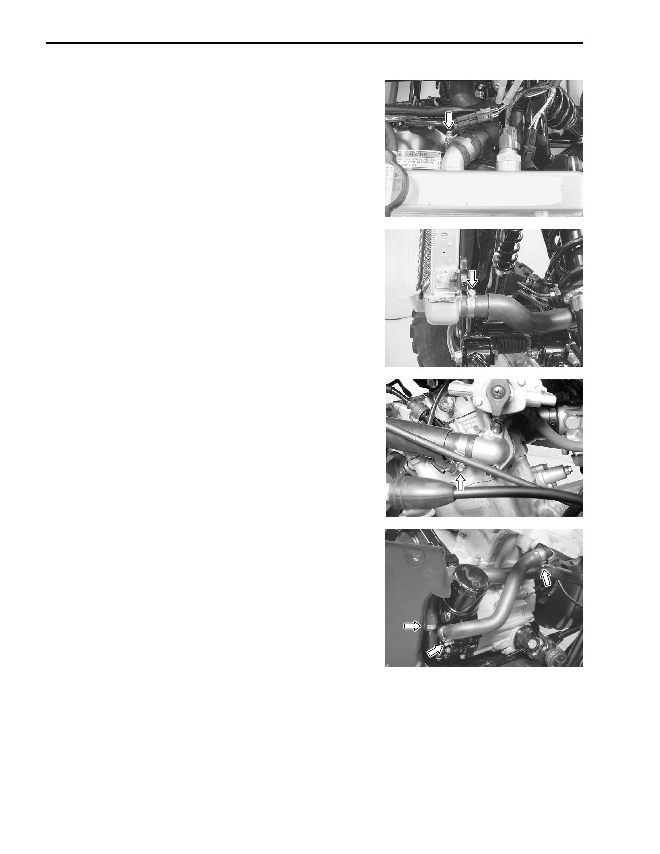
6-6 COOLING AND LUBRICATION SYSTEM
RADIATOR HOSE INSPECTION
• Remove the front fender. (#7-6)
• Any radiator hose found in a cracked condition or flattened
must be replaced.
• Any leakage from the connecting section should be corrected
by proper tightening.
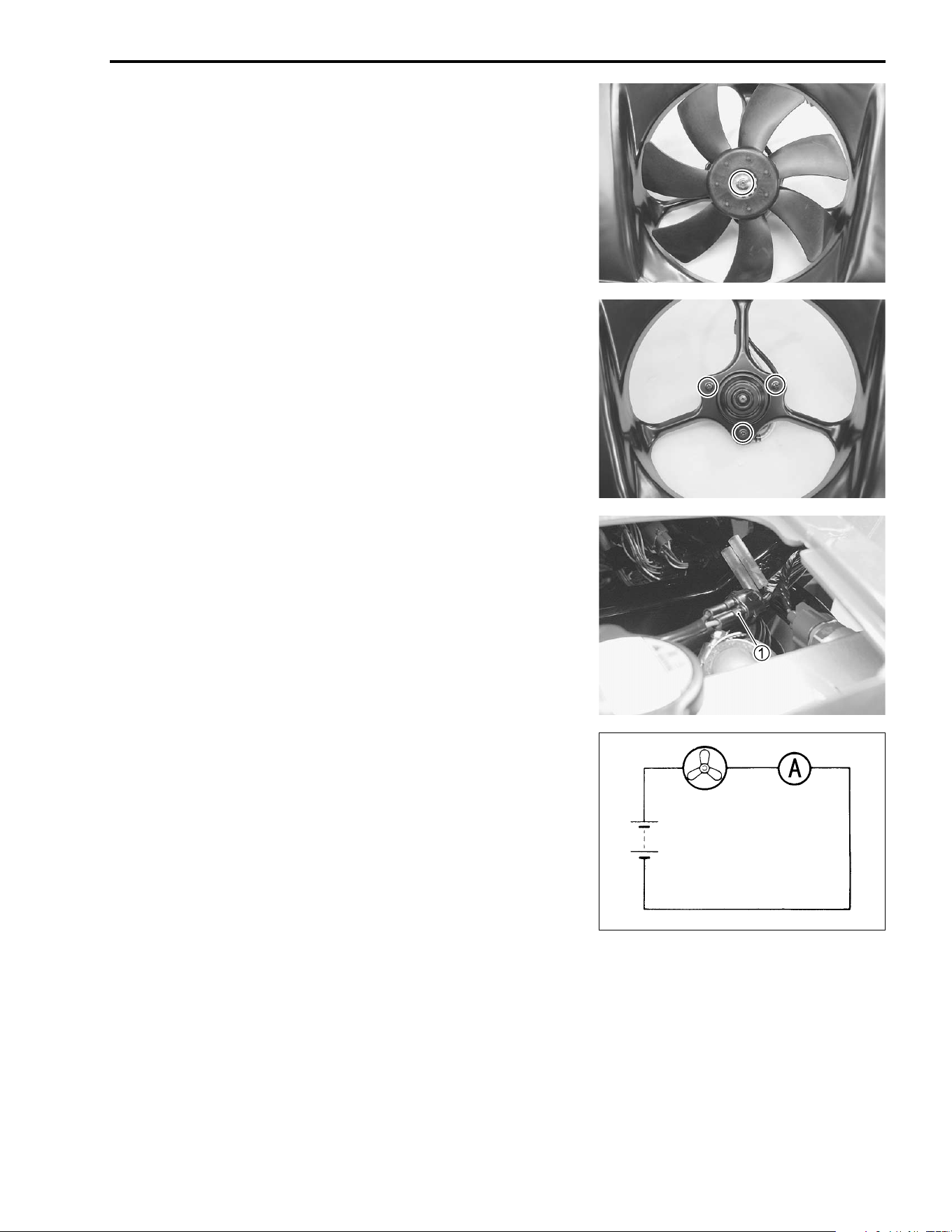
COOLING AND LUBRICATION SYSTEM 6-7
COOLING FAN
REMOVAL
• Remove the front fender. (# 7-6)
• Drain engine coolant. (#6-4)
• Remove the radiator. (#6-4)
• Remove the cooling fan.
• Remove the cooling fan motor.
INSPECTION
• Remove the radiator cap lid.
• Disconnect the cooling fan motor lead wire coupler
1.
• Test the cooling fan motor for load current with an ammeter
connected as shown in the illustration.
• The voltmeter is for making sure that the battery applies 12
volts to the motor. With the motor with electric motor fan run-
ning at full speed, the ammeter should be indicating not more
than 5 amperes.
• If the fan motor does not turn, replace the motor assembly
with a new one.
NOTE:
When making above test, it is not necessary to remove the cool-
ing fan.
Fan motor Ammeter
Battery
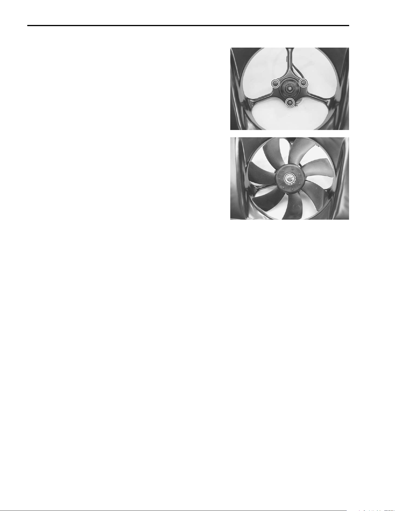
6-8 COOLING AND LUBRICATION SYSTEM
INSTALLATION
• Install the cooling fan motor and cooling fan.
% Cooling fan motor mounting screw: 8 N·m
(0.8 kgf-m, 6.0 lb-ft)
% Cooling fan nut: 10 N·m (1.0 kgf-m, 7.0 lb-ft)
• Install the radiator. (#6-4)
• Connect the radiator hoses. (#6-6, 9-18)
• Pour engine coolant. (#2-12)
• Install the front fender.
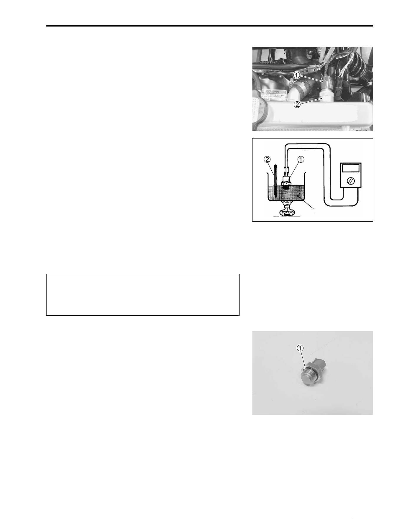
COOLING AND LUBRICATION SYSTEM 6-9
COOLING FAN THERMO-SWITCH
REMOVAL
• Remove the front fender. (# 7-6)
• Drain a small amount of engine coolant. (#6-4)
• Disconnect the cooling fan thermo-switch lead wire coupler
1.
• Remove the cooling fan thermo-switch
2.
INSPECTION
• Check the thermo-switch closing or opening temperatures by
testing it at the bench as shown in the figure. Connect the
thermo-switch
1 to a circuit tester and place it in the oil con-
tained in a pan, which is placed on a stove.
• Heat the oil to raise its temperature slowly and read the col-
umn thermometer
2 when the switch closes or opens.
& 09900-25008: Multi circuit tester set
' Tester knob indication: Continuity test (()
$ Cooling fan thermo-switch operating temperature
Standard (OFF→
→→
→ON): Approx. 88°C (190°F)
(ON→
→→
→OFF): Approx. 82°C (180°F)
!
INSTALLATION
• Install the new O-ring
1.
• Tighten the cooling fan thermo-switch to the specified torque.
% Cooling fan thermo-switch: 30 N·m (3.0 kgf-m, 21.5 lb-ft)
• Pour engine coolant. (#2-12)
• Install the front fender.
Oil
* Take special care when handling the thermo-switch.
It may cause damage if it gets a sharp impact.
* Do not contact the cooling fan thermo-switch
1 and
the column thermometer
2 with a pan.
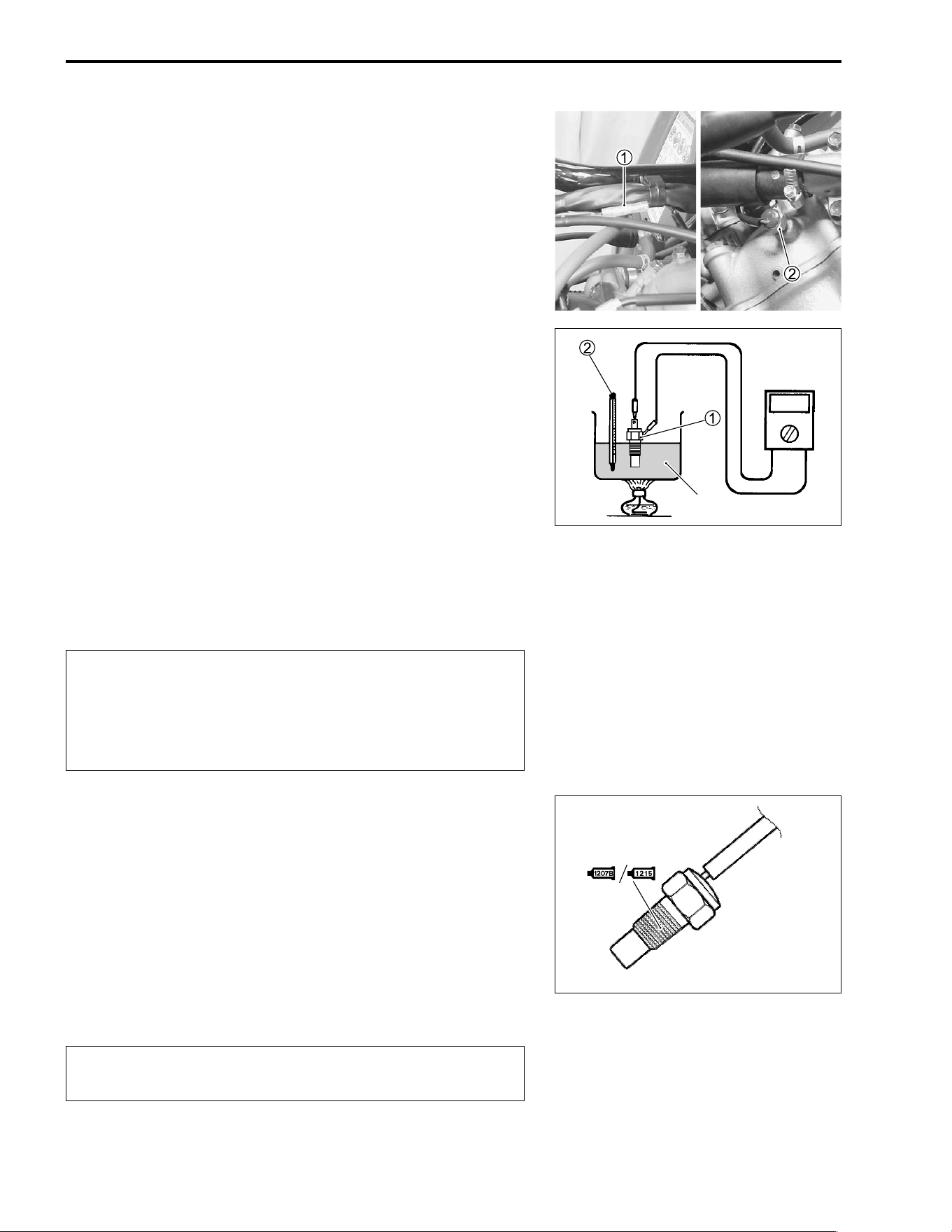
6-10 COOLING AND LUBRICATION SYSTEM
ENGINE COOLANT TEMPERATURE SWITCH
REMOVAL
• Remove the fuel tank. (#5-3)
• Drain a small amount of engine coolant. (#6-4)
• Disconnect the engine coolant temperature switch lead wire
1.
• Place a rag under the switch and remove the engine coolant
temperature swicth
2.
INSPECTION
• Check the engine coolant temperature switch by testing it at
the bench as shown in the figure. Connect the temperature
switch
1 to a circuit tester and place it in the oil contained in a
pan, which is placed on a stove.
• Heat the oil to raise its temperature slowly and read the col-
umn thermometer
2 when the switch closes or opens.
& 09900-25008: Multi circuit tester set
' Tester knob indication: Continuity test (()
$ Engine coolant temp. switch operating temperature
Standard (OFF→
→→
→ON): Approx. 115°C (239°F)
(ON→
→→
→OFF): Approx. 108°C (226°F)
!
INSTALLATION
• Apply sealant to the thread portion of the engine coolant tem-
perature switch.
) 99104-31140: SUZUKI BOND “1207B” (USA)
* 99000-31110: SUZUKI BOND “1215” (Others)
• Tighten the engine coolant temperature switch to the speci-
fied torque.
% Engine coolant temperature switch:
10 N·m (1.0 kgf-m, 7.3 lb-ft)
!
• Install the fuel tank. (#5-3)
• Pour engine coolant. (#2-12)
Oil
* Take special care when handling the temperature
switch. It may cause damage if it gets a sharp
impact.
* Do not contact the engine coolant temperature
switch
1 and the column thermometer
2 with a pan.
Take special care when handling the temperature
switch. It may cause damage if it gets a sharp impact.
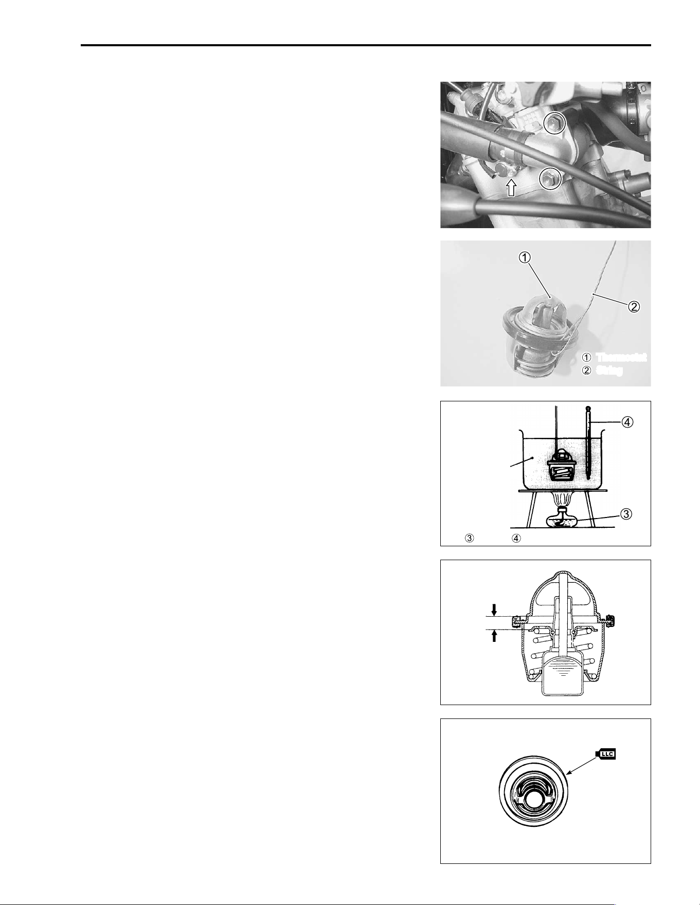
COOLING AND LUBRICATION SYSTEM 6-11
THERMOSTAT
REMOVAL
• Remove the fuel tank cover. (#7-5)
• Drain a small amount of engine coolant. (#6-4)
• Place a rag under the thermostat case.
• Remove the thermostat case.
• Remove the thermostat.
INSPECTION
Inspect the thermostat pellet for signs of cracking.
Test the thermostat at the bench for control action, in the follow-
ing manner.
• Pass a string between flange, as shown in the photograph.
• Immerse the thermostat in the water contained in a beaker, as
shown in the illustration. Note that the immersed thermostat is
in suspension. Heat the water by placing the beaker on a
stove and observe the rising temperature on a thermometer.
• Read the thermometer just when opening the thermostat. This
reading, which is the temperature level at which the thermo-
stat valve begins to open, should satisfy the standard value.
$ Thermostat valve opening temperature
Standard: 73.5 – 76.5 °C (164 – 170 °F)
• Keep on heating the water to raise its temperature.
• Just when the water temperature reaches specified value, the
thermostat valve should have lifted by at least 3.0 mm
(0.12 in).
$ Thermostat valve lift
Standard: Over 3.0 mm at 90°C (Over 0.12 in at 194°F)
• A thermostat failing to satisfy either of the two requirements
(start-to-open temperature and valve lift) must be replaced.
INSTALLATION
• Install the thermostat in the reverse order of removal.
• Apply engine coolant to the rubber seal on the thermostat.
Thermostat
String
Stove Thermometer
Water
Valve lift
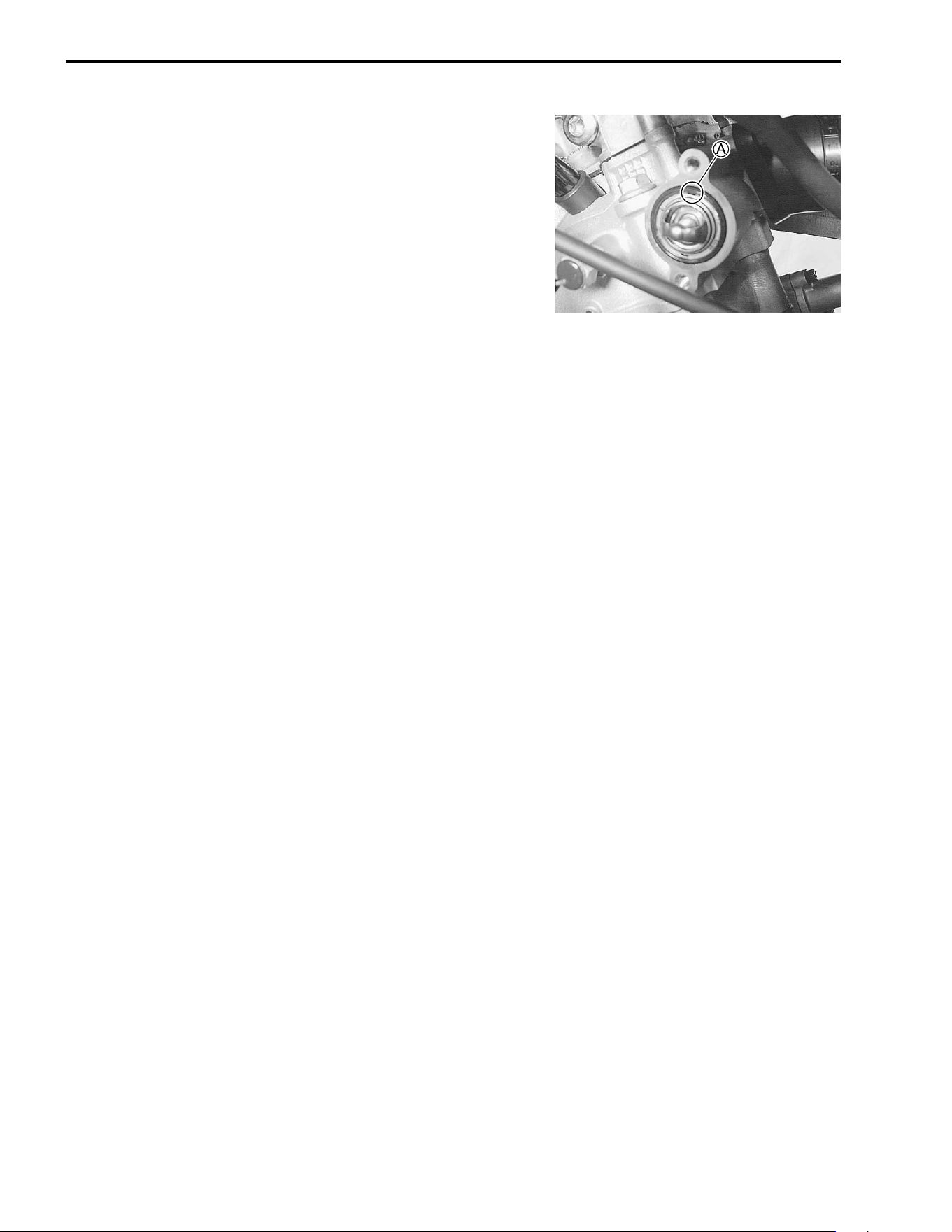
6-12 COOLING AND LUBRICATION SYSTEM
NOTE:
The hole
A of the thermostat faces upside.
• After installing the thermostat, be sure to add engine coolant.
(#2-12)
• Tighten the thermostat case bolts to the specified torque.
• Install the fuel tank cover. (#7-5)
% Thermostat case bolt: 10 N·m (1.0 kgf-m, 7.0 lb-ft)
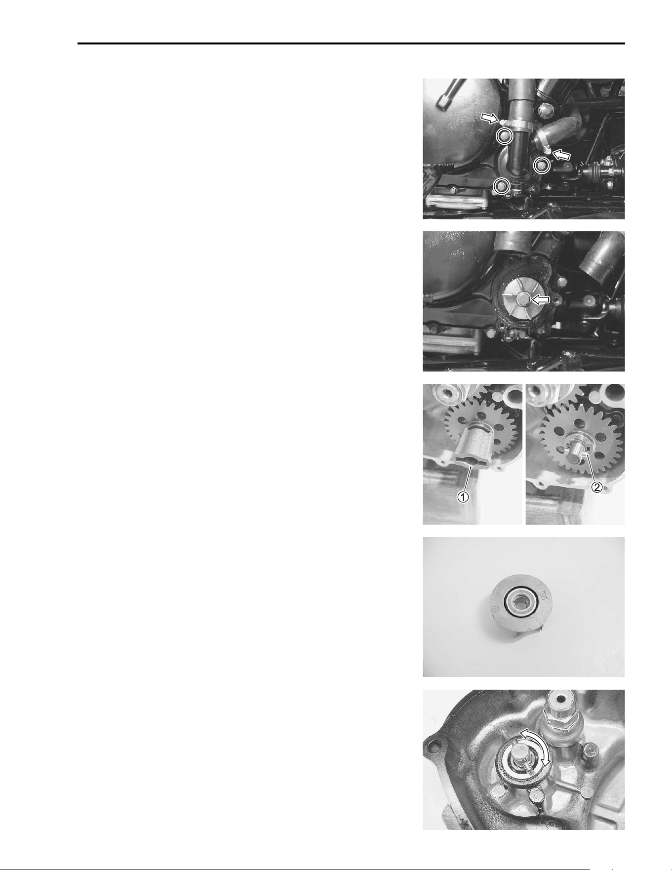
COOLING AND LUBRICATION SYSTEM 6-13
WATER PUMP
REMOVAL
• Remove the right inner fender. (#7-6)
• Remove the right mud guard. (#7-8)
• Drain engine coolant. (#6-4)
• Disconnect the water hoses.
• Remove the water pump cover bolts.
• Remove the impeller securing bolt with a water pump plier.
• Drain engine oil. (#2-9)
• Remove the right mud guard. (#7-8)
• Remove the right footrest. (#3-6)
• Remove the generator cover. (#3-17)
• Remove the water pump drive joint
1.
• Remove the pin
2.
INSPECTION
MECHANICAL SEAL
Visually inspect the mechanical seal for damage, with particular
attention given to the sealing face. Replace the mechanical seal
that shows indications of leakage. Also replace the oil seal if
necessary.
WATER PUMP SHAFT
Rotate the water pump shaft assembly by hand to inspect for
abnormal noise and smooth rotation. If anything unusual is
found, replace the water pump shaft assembly with a new one. If
there is no abnormal condition you need not disassembly.
NOTE:
The water pump shaft is igtegrated with the water pump bearing.
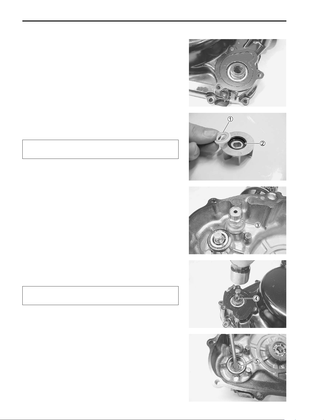
6-14 COOLING AND LUBRICATION SYSTEM
MECHANICAL SEAL
Visually inspect the mechanical seal for damage, with particular
attention given to the sealing face. Replace the mechanical seal
that shows indications of leakage. Also replace the seal ring if
necessary.
DISASSEMBLY
• Remove the mechanical seal ring
1 and seal
2.
!
• Remove the oil pressure switch
3.
NOTE:
When removing the water pump shaft, mechanical seal and
seal, remove the oil pressure switch to protect it from damage.
• Attach a proper 6 mm bolt to the water pump shaft
4 and
remove the water pump shaft.
!
• Remove the oil seal
5.
The removed mechanical seal and seal must be
replaced with new ones.
Be careful not to crush the thread of the water pump
shaft.
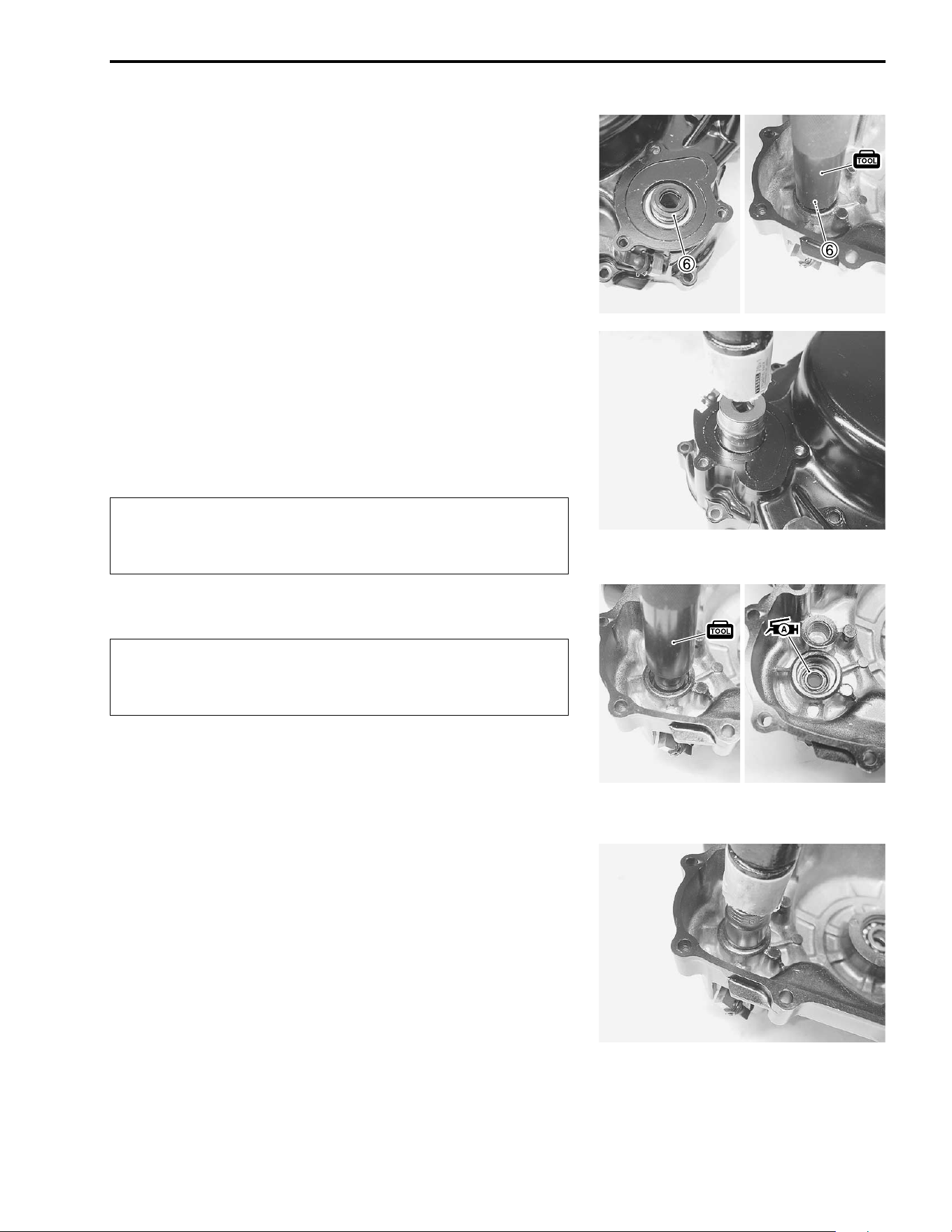
COOLING AND LUBRICATION SYSTEM 6-15
• Remove the mechanical seal
6 with the special tool.
& 09913-70210: Bearing installer set
REASSEMBLY AND INSTALLATION
Reassemble and remount the water pump in the reverse order
of removal and disassembly. Pay attention to the following
points:
• Install the mechanical seal by using the suitable size socket
wrench.
!
• Install the oil seal with the special tool.
!
• Apply grease to the oil seal.
& 09913-70210: Bearing installer set
+ 99000-25030: SUZUKI SUPER GREASE “A” (USA)
99000-25010: SUZUKI SUPER GREASE “A” (Others)
• Install the water pump shaft by using the suitable size socket
wrench.
• Install the new gasket. (#3-96)
* Replace the removed seal with a new one.
* Install the mechanical seal taking care about its
direction. (#6-17)
* Replace the removed seal with a new one.
* Install the oil seal taking care about its direction.
(#6-17)
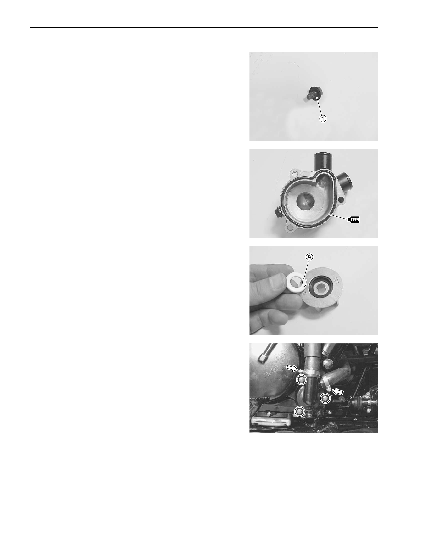
6-16 COOLING AND LUBRICATION SYSTEM
• Tighten the impeller securing bolt to the specified torque with
a water pump plier.
% Impeller securing bolt: 15 N·m (1.5 kgf-m, 11.0 lb-ft)
NOTE:
The seal lip side
1 must face to impeller.
• Replace the O-ring with a new one.
NOTE:
Apply engine coolant to the O-ring.
NOTE:
The mechanical seal ring must be assembled with the paint
marked
A face of the ring toward the impeller.
• Install the water pump cover and tighten its mounting bolts
securely.
• Connect the water hoses.
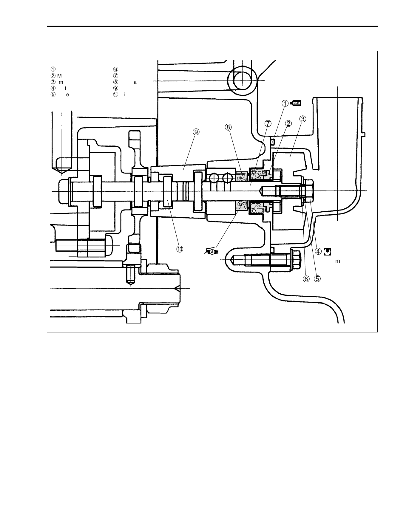
COOLING AND LUBRICATION SYSTEM 6-17
LUBRICATION SYSTEM
OIL PRESSURE
#2-25
OIL FILTER
#2-10
OIL PRESSURE REGULATOR
#3-56
OIL SUMP FILTER
#3-51
OIL PUMP
#3-21, 3-51, 3-84
1
O-ring
2
Mechanical seal
3
Impeller
4
Water pump shaft bolt
5
Impeller washer
6
Seal washer
7
Shaft
8
Oil seal
9
Joint
0
Pin
15 N
.
m
(1.5 kgf-m, 11.0 lb-ft)
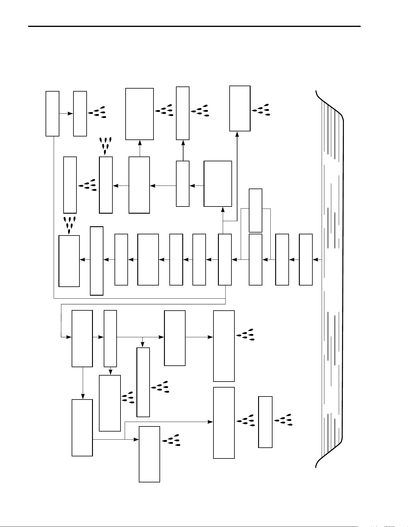
6-18 COOLING AND LUBRICATION SYSTEM
ENGINE LUBRICATION SYSTEM CHART
OIL PAN
OIL SUMP FILTER
OIL PUMP
OIL FILTER
RELIEF VALVE
FIRST CLUTCH
SHOE
OIL GALLERY
CRANKSHAFT
RIGHT END
BEARING
CYLINDER
CYLINDER HEAD
CRANKSHAFT
STARTER CLUTCH
CYLINDER WALL
PISTON WALL
PISTON RING
CONROD BIG-END
BEARING
STARTER CLUTCH
PISTON PIN
OIL NOZZLE
CAM DRIVE CHAIN
IN. & EX.
CAM FACES
IN. ROCKER ARM SHAFT
CAMSHAFT
CYLINDER HEAD
COVER
SECOND CLUTCH
DRIVE & DRIVEN PLATES
DRIVESHAFT GEARS &
REVERSE GEARS
BEVEL GEARS
PRIMARY DRIVEN
GEAR SPACER
COUNTERSHAFT GEARS
COUNTERSHAFT
COUNTERSHAFT
LEFT END BEARING
DRIVESHAFT
LEFT END BEARING
TRANSFER-MISSION
INPUT GEARS
TRANSFER-MISSION
IDLER GEARS
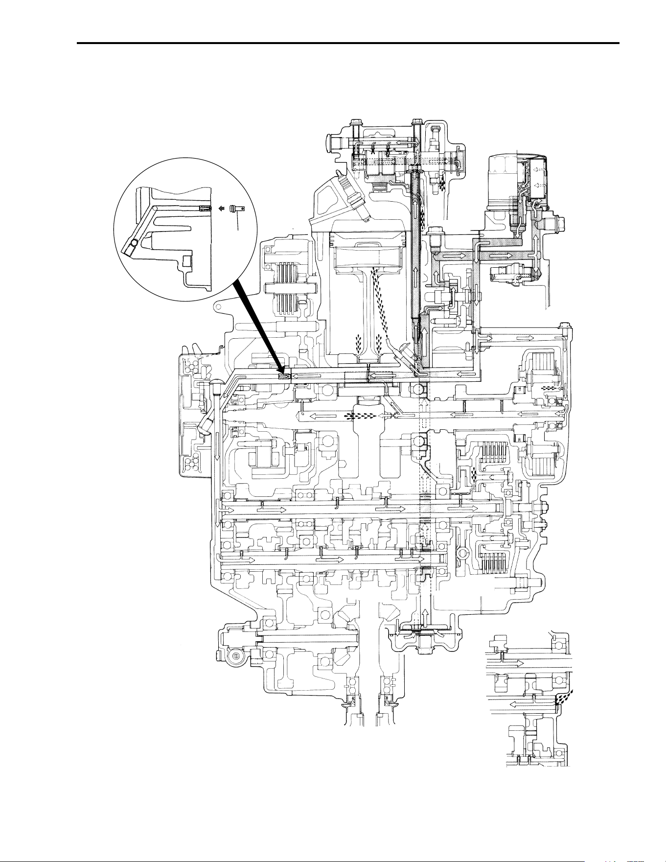
COOLING AND LUBRICATION SYSTEM 6-19
ENGINE LUBRICATION SYSTEM
\
Oil jet

7
CHASSIS 7-1
CONTENTS
CHASSIS
EXTERIOR PARTS .................................................................................................................... 7- 2
CONSTRUCTION ............................................................................................................. 7- 2
REMOVAL ........................................................................................................................7- 4
REMOUNTING .................................................................................................................. 7-10
FRONT AND REAR WHEELS .................................................................................................. 7-11
CONSTRUCTION ............................................................................................................. 7-11
REMOVAL ........................................................................................................................7-11
REMOUNTING .................................................................................................................. 7-11
TIRES ......................................................................................................................................... 7-12
TIRE REPLACEMENT ...................................................................................................... 7-12
FRONT DRIVE SHAFT ..............................................................................................................7-14
CONSTRUCTION ............................................................................................................. 7-14
REMOVAL ........................................................................................................................7-14
INSPECTION AND DISASSEMBLY ................................................................................ 7-14
REMOUNTING .................................................................................................................. 7-18
FRONT BRAKE ......................................................................................................................... 7-19
CONSTRUCTION ............................................................................................................. 7-19
BRAKE PAD REPLACEMENT ........................................................................................ 7-20
BRAKE FLUID REPLACEMENT ..................................................................................... 7-21
BRAKE CALIPER REMOVAL AND DISASSEMBLY ...................................................... 7-21
BRAKE CALIPER INSPECTION ...................................................................................... 7-23
BRAKE CALIPER REASSEMBLY AND REMOUNTING ................................................ 7-24
BRAKE DISC REMOVAL AND DISASSEMBLY ............................................................. 7-26
BRAKE DISC INSPECTION ............................................................................................. 7-27
BRAKE DISC REASSEMBLY AND REMOUNTING ....................................................... 7-27
MASTER CYLINDER REMOVAL AND DISASSEMBLY ................................................. 7-28
MASTER CYLINDER INSPECTION ................................................................................. 7-30
MASTER CYLINDER REASSEMBLY AND REMOUNTING ........................................... 7-30
FRONT SUSPENSION .............................................................................................................. 7-32
CONSTRUCTION ............................................................................................................. 7-32
REMOVAL AND DISASSEMBLY .................................................................................... 7-33
INSPECTION .................................................................................................................... 7-35
REASSEMBLY AND REMOUNTING ............................................................................... 7-38
STEERING ................................................................................................................................. 7-41
CONSTRUCTION ............................................................................................................. 7-41
REMOVAL AND DISASSEMBLY .................................................................................... 7-42
INSPECTION .................................................................................................................... 7-44
REASSEMBLY AND REMOUNTING ............................................................................... 7-46
TOE-IN ADJUSTMENT .................................................................................................... 7-48
FRONT WHEEL, FRONT BRAKE, FRONT SUSPENSION AND
STEERING REASSEMBLING INFORMATION ........................................................................ 7-49
REAR BRAKE ........................................................................................................................... 7-50
CONSTRUCTION ............................................................................................................. 7-50
BRAKE PAD REPLACEMENT ........................................................................................ 7-51
BRAKE FLUID REPLACEMENT ..................................................................................... 7-52
BRAKE CALIPER REMOVAL AND DISASSEMBLY ...................................................... 7-52
BRAKE CALIPER INSPECTION ...................................................................................... 7-54
BRAKE CALIPER REASSEMBLY AND REMOUNTING ................................................ 7-55
BRAKE DISC REMOVAL AND DISASSEMBLY ............................................................. 7-57
BRAKE DISC INSPECTION ............................................................................................. 7-57
BRAKE DISC REASSEMBLY AND REMOUNTING ....................................................... 7-58
MASTER CYLINDER REMOVAL AND DISASSEMBLY ................................................. 7-59
MASTER CYLINDER INSPECTION ................................................................................. 7-60
MASTER CYLINDER REASSEMBLY AND REMOUNTING ........................................... 7-61
REAR SUSPENSION ................................................................................................................7-63
CONSTRUCTION ............................................................................................................. 7-63
REMOVAL ........................................................................................................................7-64
INSPECTION AND DISASSEMBLY ................................................................................ 7-65
REASSEMBLY AND REMOUNTING ............................................................................... 7-66
REAR AXLE .............................................................................................................................. 7-68
CONSTRUCTION ............................................................................................................. 7-68
REMOVAL ........................................................................................................................7-69
INSPECTION AND DISASSEMBLY ................................................................................ 7-69
REASSEMBLY AND REMOUNTING ............................................................................... 7-71
REAR WHEEL, REAR BRAKE, REAR SUSPENSION, REAR SWINGARM AND
REAR AXLE SHAFT REASSEMBLING INFORMATION ......................................................... 7-73
GEARSHIFT LEVER ................................................................................................................. 7-74
CONSTRUCTION ............................................................................................................. 7-74
REMOVAL AND DISASSEMBLY .................................................................................... 7-75
INSPECTION .................................................................................................................... 7-76
REASSEMBLY AND REMOUNTING ............................................................................... 7-77
CABLES .................................................................................................................................... 7-79
REMOVAL AND INSTALLATION .................................................................................... 7-79
CABLE PLAY ADJUSTMENT .......................................................................................... 7-83
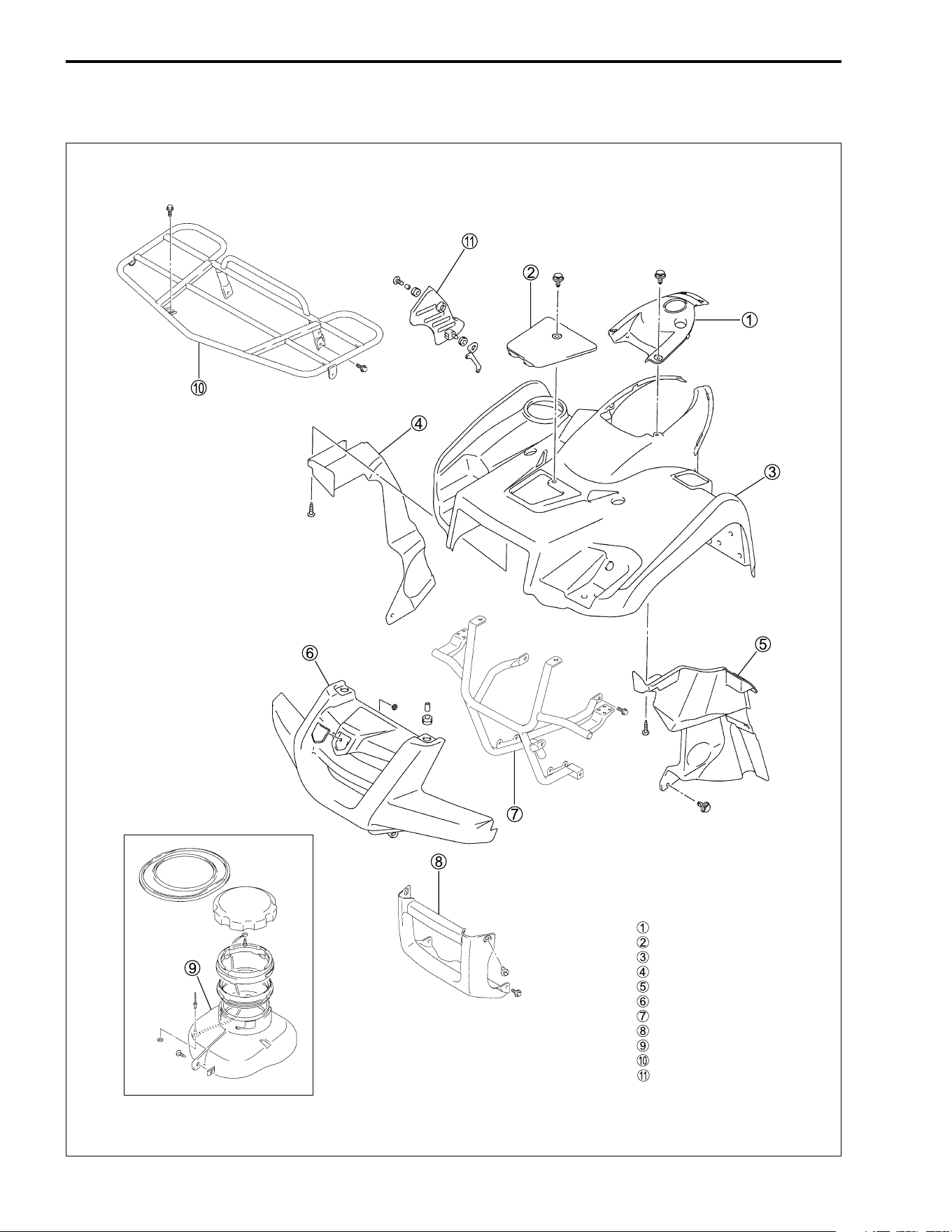
7-2 CHASSIS
EXTERIOR PARTS
CONSTRUCTION
Fuel tank top cover
Lid
Front fender
Front inner fender (RH)
Front inner fender (LH)
Front grill upper
Front grip bar
Front grill lower
Front box
Front carrier
Muffler cover
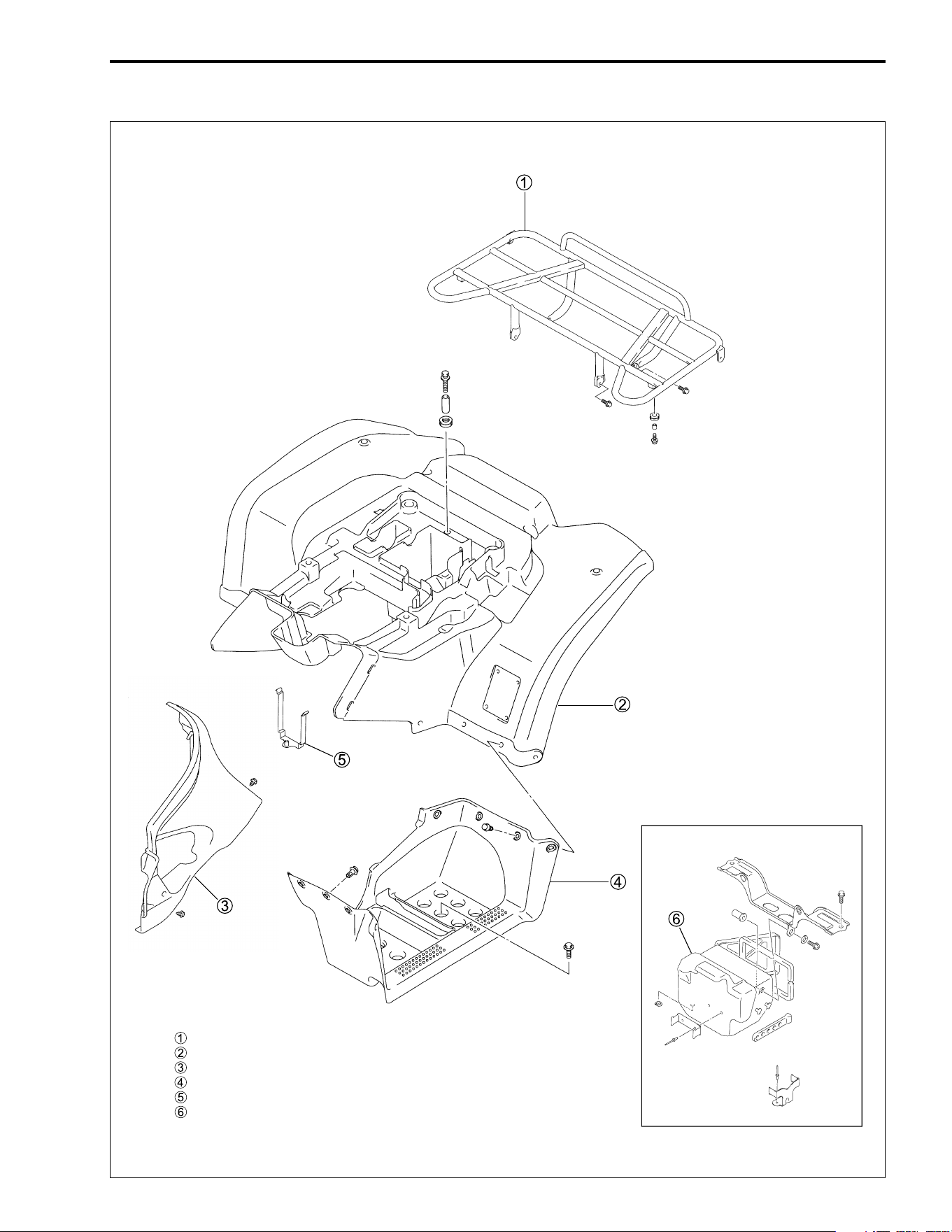
CHASSIS 7-3
Rear carrier
Rear fender
Fuel tank cover
Mud guard
Battery holder plate
Rear box
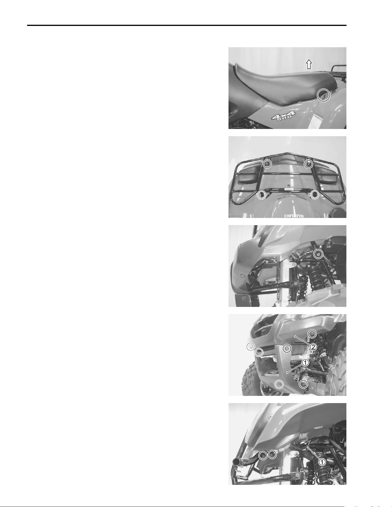
7-4 CHASSIS
REMOVAL
SEAT
• Remove the seat.
FRONT CARRIER
• Remove the front carrier.
GRILL UPPER/LOWER COVERS
• Remove the grill lower cover
1.
• Remove the front carrier. (!Abobe)
• Remove the grill upper cover
2.
FRONT GRIP BAR
• Remove the grill upper/lower covers. (!Abobe)
• Disconnect the headlight couplers
1.
• Remove the headlight mounting nuts.
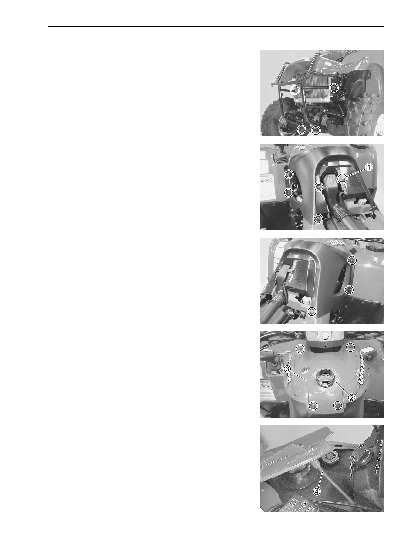
CHASSIS 7-5
• Remove the front grip bar.
FUEL TANK COVERS
• Remove the seat. (!7-4)
• Remove the air cleaner duct mounting screw
1.
• Remove the fuel tank covers.
NOTE:
Before removing the fuel tank covers, do not attempt to uncou-
ple the fuel tank covers.
• Remove the fuel tank cap.
• Remove the fuel tank inlet cover
2.
• Remove the fuel tank top cover
3.
• Disconnect the fuel breather hose
4.
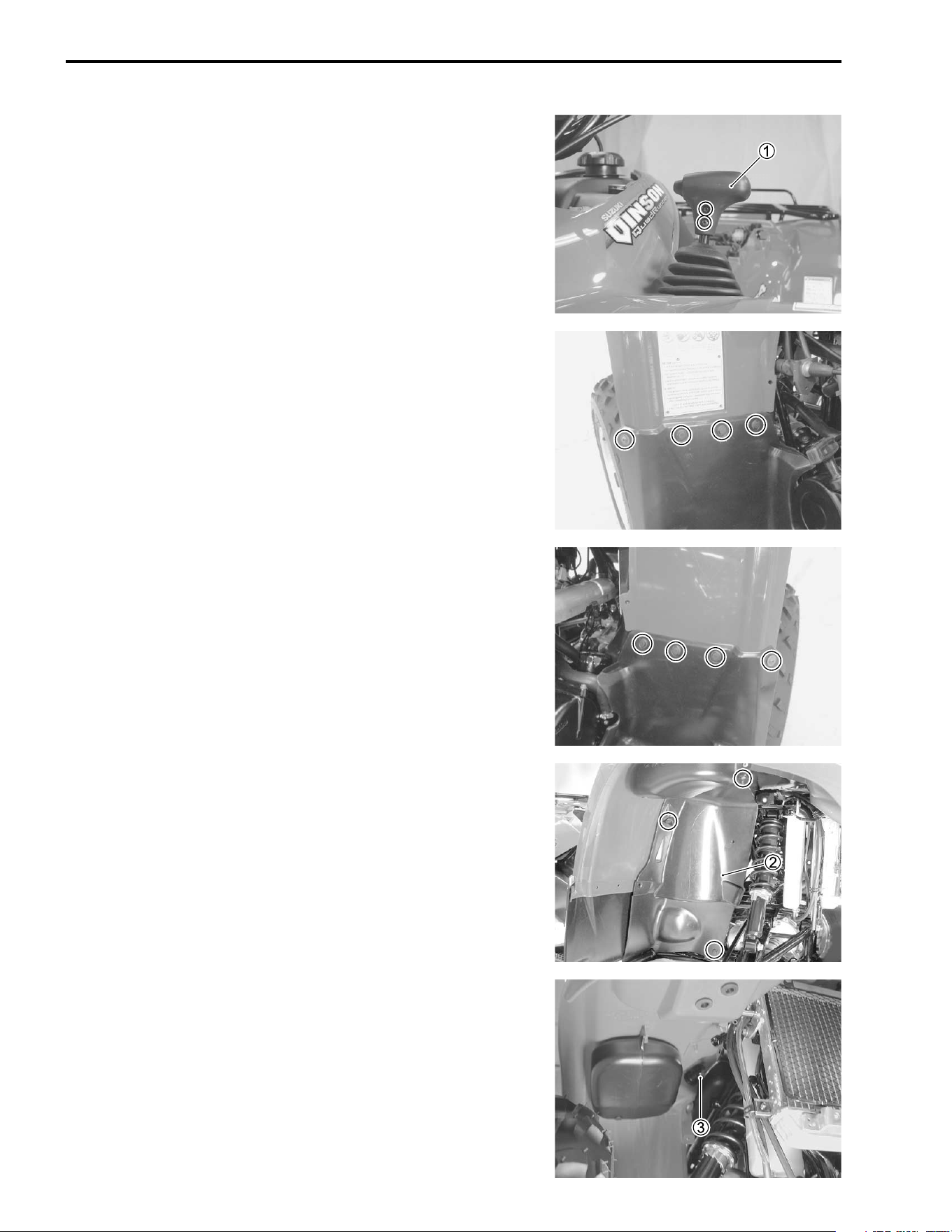
7-6 CHASSIS
FRONT FENDER
• Remove the seat. (!7-4)
• Remove the front grip bar. (!7-4)
• Remove the fuel tank covers. (!7-5)
• Remove the gearshift lever knob
1.
• Remove the right and left mud guard fasteners/screws.
• Remove the right inner fender
2.
• Remove the power source coupler
3.
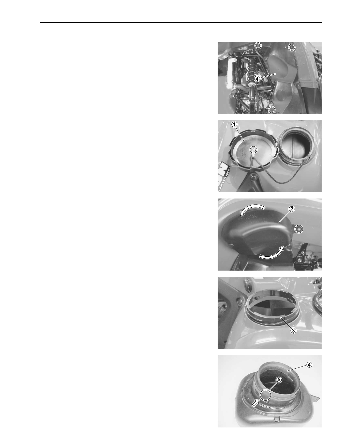
CHASSIS 7-7
• Remove the left inner fender
4.
• Remove the front fender.
FRONT BOX
• Remove the front box cap
1.
• Remove the front box mounting screw.
• Turn the front box
2 counterclockwise and remove it.
• Remove the front box holder
3.
• Remove the cushion
4 from the front box.
NOTE:
When installing the cushion to the front box, align
A to the cut-
out on the front box.
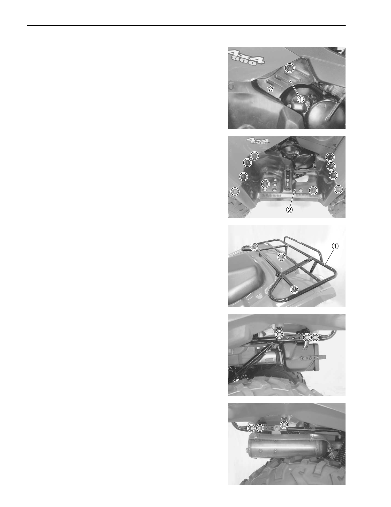
7-8 CHASSIS
MUD GUARD
• Remove the muffler cover
1. (Right side)
✩: hooked part
• Remove the mud guard
2.
REAR CARRIER
• Remove the rear carrier
1.
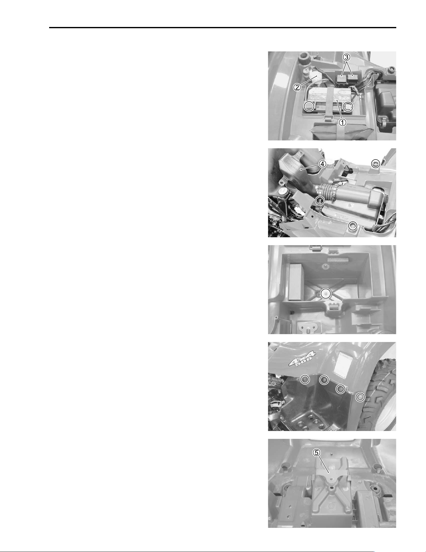
CHASSIS 7-9
REAR FENDER
• Remove the fuel tank covers. (!7-5)
• Remove the rear carrier. (!7-8)
• Remove the battery
1 and its tray.
• Remove the starter motor relay
2 and fuse box/neutral relay
3 from the rear fender.
• Remove the air cleaner duct
4.
• Remove the rear fender bolts.
• Remove the rear fender bolt.
• Remove the right and left mud guard fasteners/screws.
• Remove the rear fender.
• Remove the battery holder plate
5.
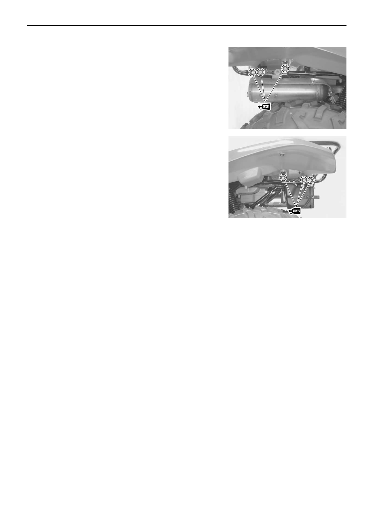
7-10 CHASSIS
REMOUNTING
Remounting the exterior parts in reverse order of removal. Pay
attention the following points:
REAR CARRIER
• Apply THREAD LOCK “1342” to the rear carrier mounting
bolts.
" 99000-32050: THREAD LOCK “1342”
CHASSIS 7-11
FRONT AND REAR WHEELS
CONSTRUCTION
REMOVAL
• Place the vehicle on level ground.
• Support the vehicle with a jack or wooden block.
• Remove the wheel set nuts.
• Remove the front and rear wheels.
REMOUNTING
Remount the wheels in the reverse order of removal. Pay atten-
tion to the following points:
• When installing each wheel, make sure the arrow
A on the
tire points in the direction of rotation.
• Tighten the wheel set nuts to the specified torque.
# Front and rear wheel set nut:
50 N·m (5.0 kgf-m, 36.0 lb-ft)
ITEM N·m kgf-m lb-ft
A
50 5.0 36.0
@
A
Wheel set nut
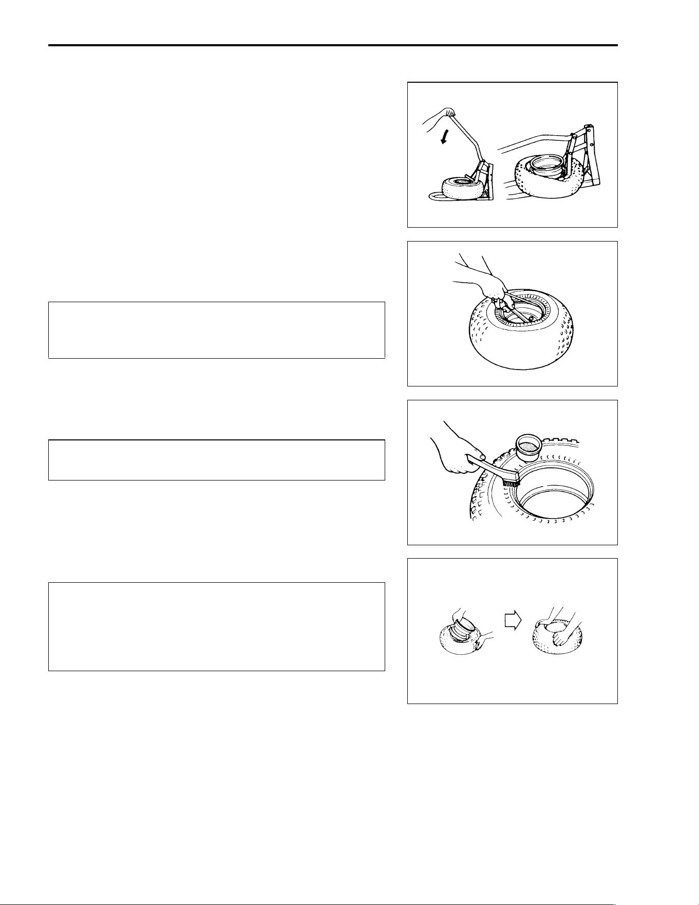
7-12 CHASSIS
TIRES
TIRE REPLACEMENT
• Remove the front and rear wheels. (!7-11)
• After removing the air valve cap, release the tire pressure by
depressing the valve.
• Dismount the bead from the rim completely as shown.
• Separate the tire from the rim by using a set of tire levers and
rim protectors.
$
• Apply tire lubricant to the tire bead and the flange of the rim.
$
$
• Mount the tire on the rim by hand as shown.
NOTE:
Inspect the sealing portion of the rim before installing the tire on
the rim.
When using the tire lever, do not scratch or hit the
sealing portion (hump) of the wheel or it may cause
air-leakage.
Never apply grease, oil, or gasoline to the tire bead
because they will deteriorate the tire.
The standard tire fitted on this vehicle is AT25 ×
8-
12✩✩
✩✩✩✩
✩✩ for the front and AT25 ×
10-12✩✩
✩✩✩✩
✩✩ for the rear.
The use of tires other than the standard may cause
instability. It is highly recommended to use the speci-
fied tire.
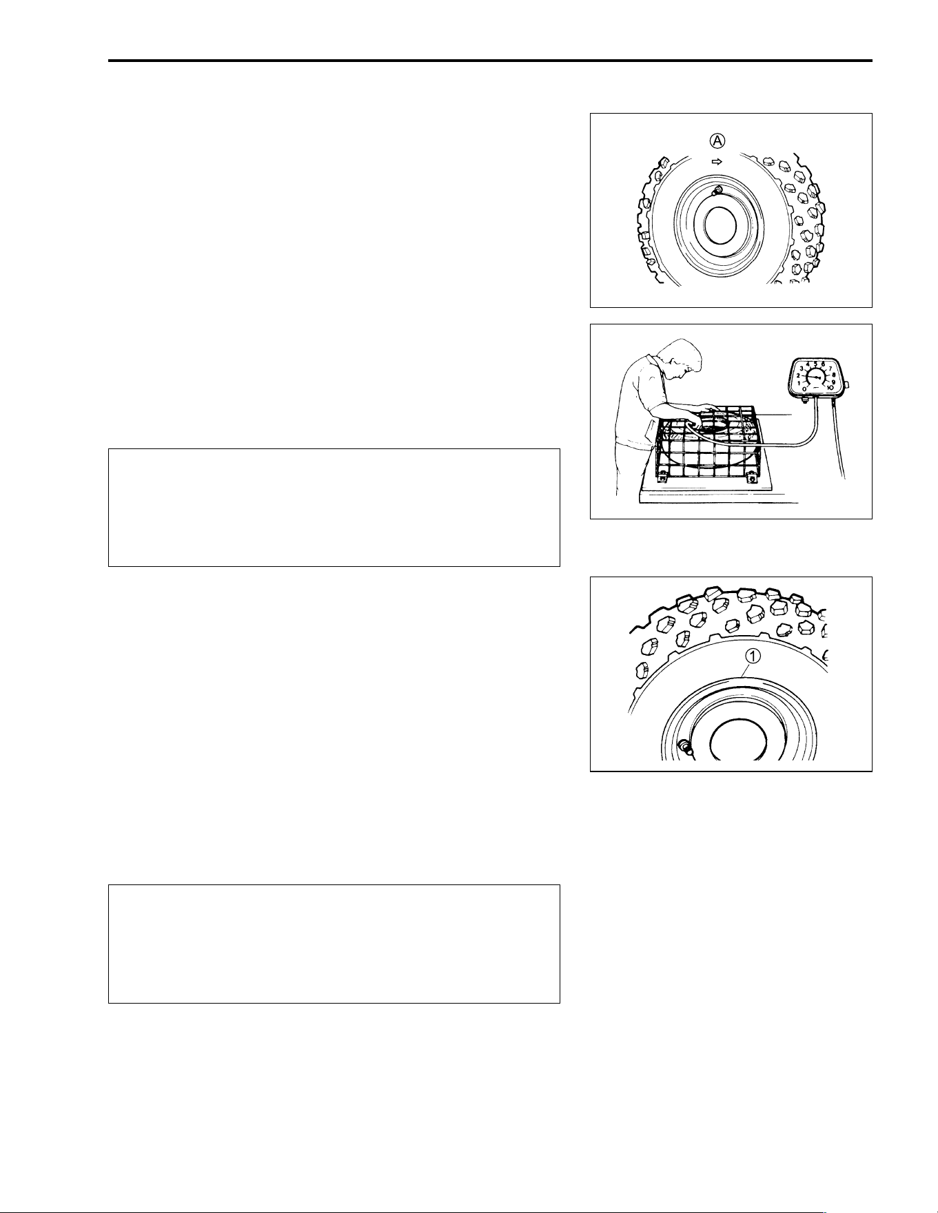
CHASSIS 7-13
• When installing each tire, make sure the arrow
A on the tire
points in the direction of rotation. Also, make sure the outer
side of the wheel rim is facing outward.
NOTE:
For inspecting the tire refer to page 2-18.
Inspect the valve core, before installation.
• Inflate the tire to seat the tire bead.
% Maximum tire bead seat pressure
Front : 250 kPa (2.5 kgf/cm², 36 psi)
Rear : 250 kPa (2.5 kgf/cm², 36 psi)
$
NOTE:
Check the “rim line”
1 cast on the tire side walls. It must be
equidistant from the wheel rim all the way around. If the distance
between the rim line and the wheel rim varies this indicates that
the bead is not properly seated. If this is so, deflate the tire com-
pletely, and unseat the tire bead on both sides. Then, coat the
bead with clean water, and re-seat the tire.
• Adjust the tire pressure to specification.
% Cold inflation tire pressure
Front : 35 kPa (0.35 kgf/cm
2
, 5.1 psi)
Rear : 30 kPa (0.30 kgf/cm
2
, 4.4 psi)
% Vehicle load capacity: 172 kg (380 lbs)
$
% Maximum operating pressure
✩
✩✩
✩: 25 kPa (0.25 kgf/cm
2
, 3.6 psi)
✩✩
✩✩✩✩
✩✩: 35 kPa (0.35 kgf/cm
2
, 5.1 psi)
✩✩✩
✩✩✩✩✩✩
✩✩✩: 45 kPa (0.45 kgf/cm
2
, 6.5 psi)
Place the tire under a protective tire cage or similar
protective covering device before inflating the tire. To
minimize the possibility of tire damage when seating
the tire bead, never exceed the MAXIMUM TIRE BEAD
SEAT PRESSURE rating shown on the tire.
Before inflating the tire, check the MAXIMUM OPER-
ATING PRESSURE rating of the tire. This is indicated
by a “✩
✩✩
✩” following the tire size shown on the sidewall.
The number of “✩
✩✩
✩” on the tire indicates the maximum
operating pressure.
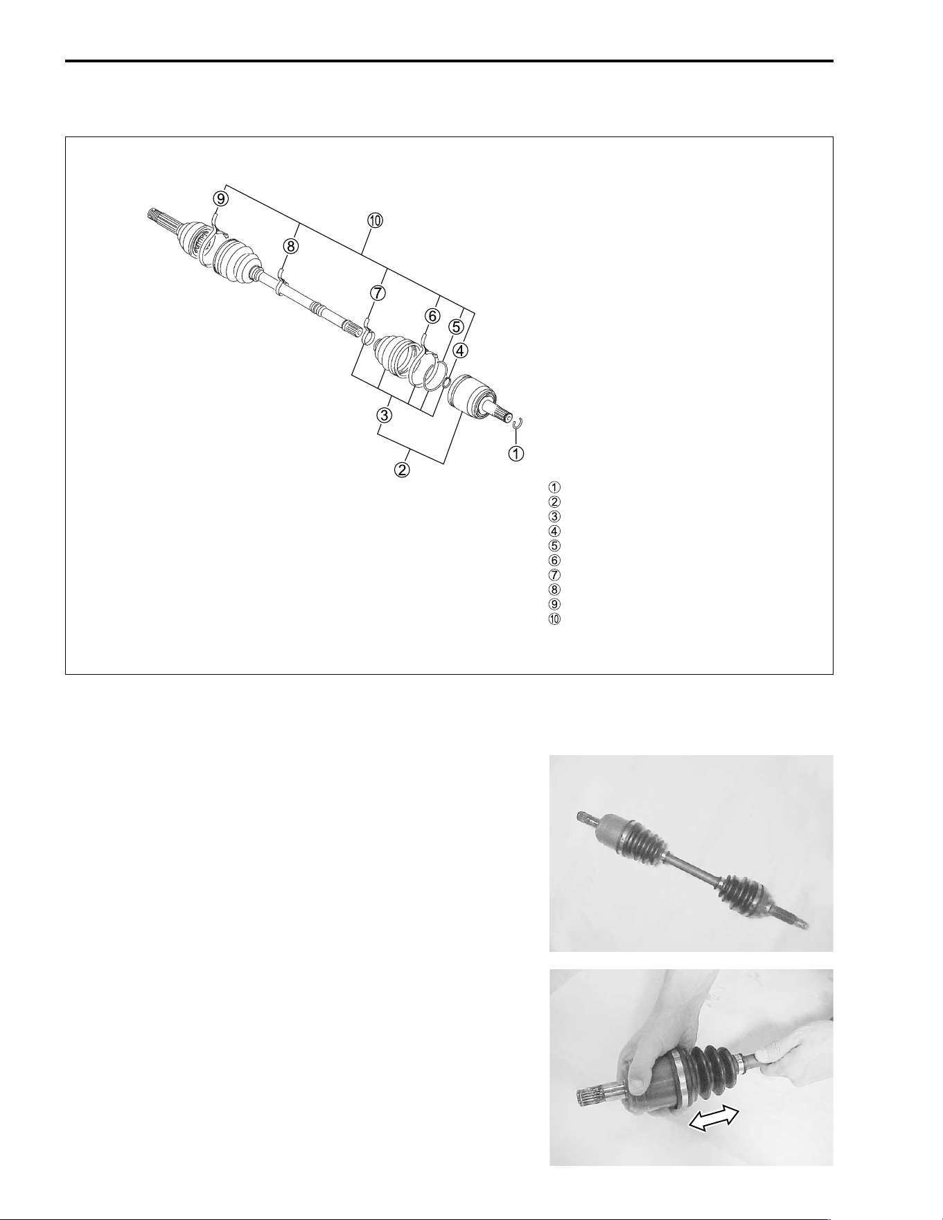
7-14 CHASSIS
FRONT DRIVE SHAFT
CONSTRUCTION
REMOVAL
• Remove the front drive shaft. (!4-3)
INSPECTION AND DISASSEMBLY
Inspect the boots for wear or damage. If any damages are
found, replace the boots with new ones.
Inspect the stopper ring, snap ring and boot bands for wear or
damage. If any damages are found, replace them with new
ones.
Inspect the axle play by using a push-and-pull motion given to
the axle shaft and wheel spindle, as shown.
Circlip
Differential side joint set
Differential side boot set
Snap ring
Circlip
Differential side outer boot clamp
Differential side inner boot clamp
Wheel side inner boot clamp
Wheel side outer boot clamp
Boot set
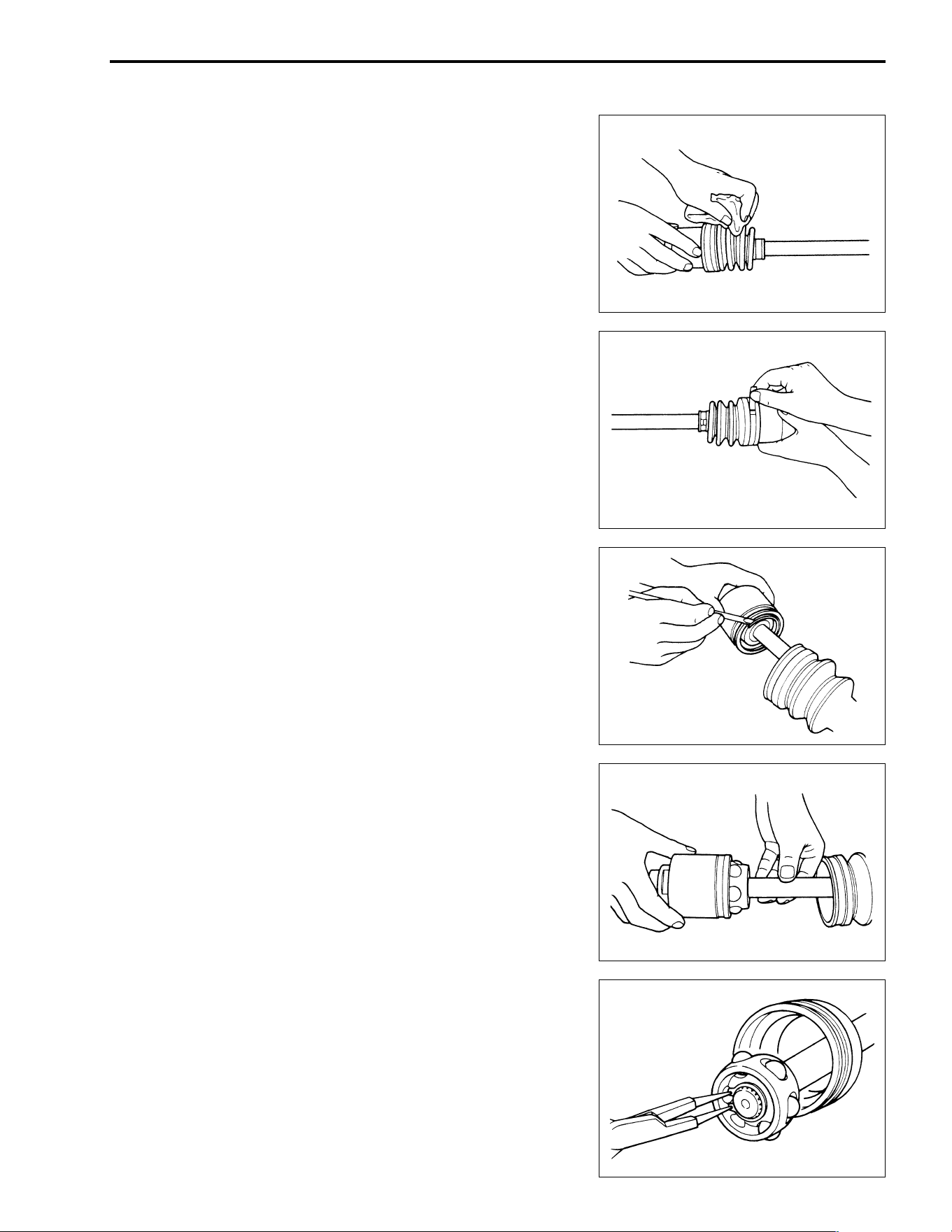
CHASSIS 7-15
• Clean the front drive shaft.
• Remove the boot bands of the differential side joint (double
offset joint).
• Slide the boot toward to the center of the front drive shaft and
remove the stopper ring from the outer race.
• Separate the outer race from the front drive shaft.
• Wipe off grease and remove the snap ring from the drive
shaft.
• Remove the cage.
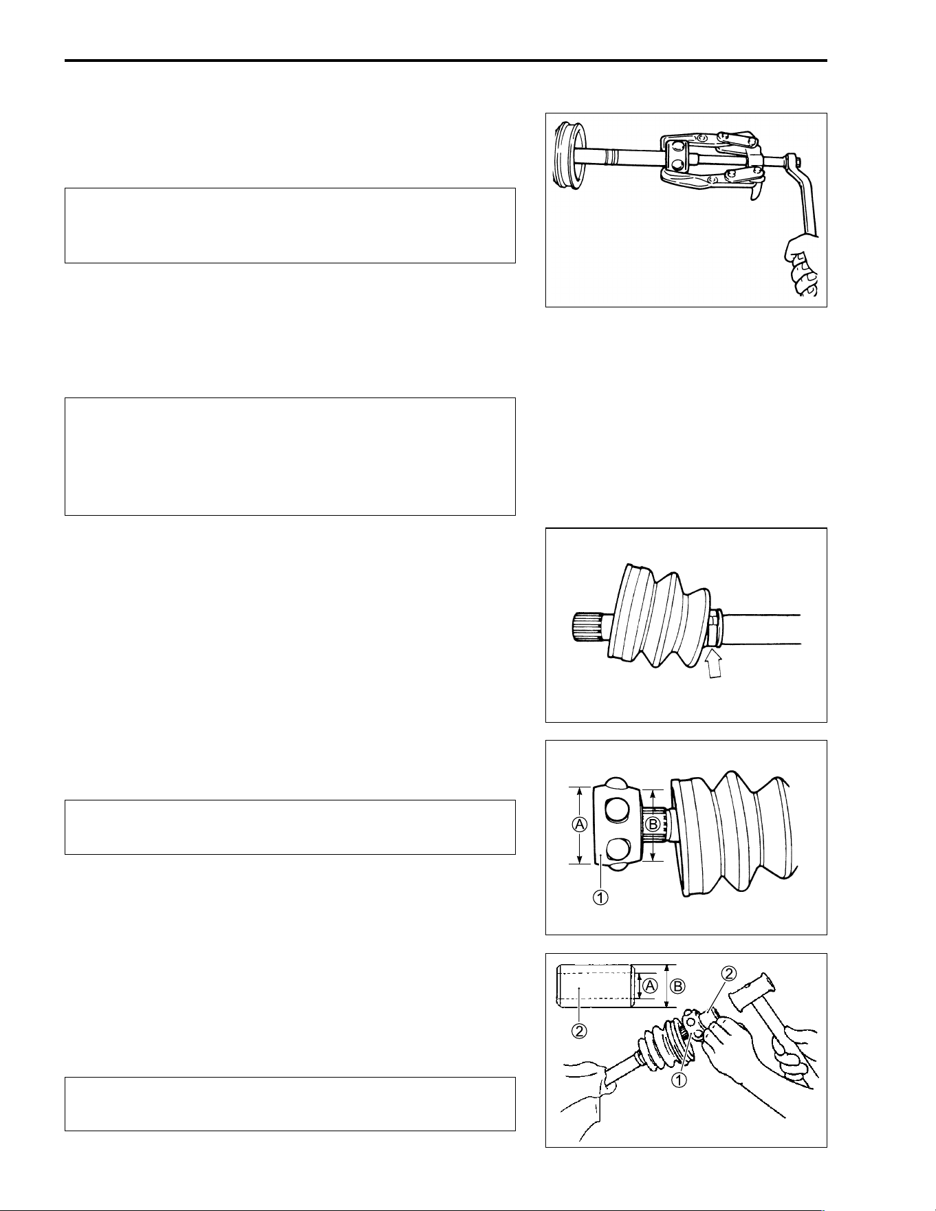
7-16 CHASSIS
• Remove the inner race with a bearing puller.
• Remove the boot.
$
NOTE:
* Wash the disassembled parts (except for the boot). After
washing, completely dry the parts using compressed air.
* Clean the boots with a cloth.
$
• Fit a boot on the drive shaft end, fitting the small diameter side
of the boot to the shaft groove, fix its end with a new band.
• Install the cage
1 on the shaft.
$
A Large diameter
B Small diameter
• Drive in the cage
1 by using a pipe
2.
Drive shaft joint cage installing pipe diameter
A : 20.0 mm (0.787 in) or more
B : 27.0 mm (1.063 in) or less
$
Do not disassemble the wheel side joint (double offset
joint). If any damages are found, replace the wheel
side joint with a new one.
* Wash all parts before installation, clean the inside
and outside of the boot with a cloth.
* Do not wash the boots in any commercially available
degreaser, such as gasoline or kerosene. Washing in
a degreaser causes deterioration of the boot.
Install the cage with the large diameter side facing the
shaft end.
Install cage directing smaller outside diameter side to
wheel side.
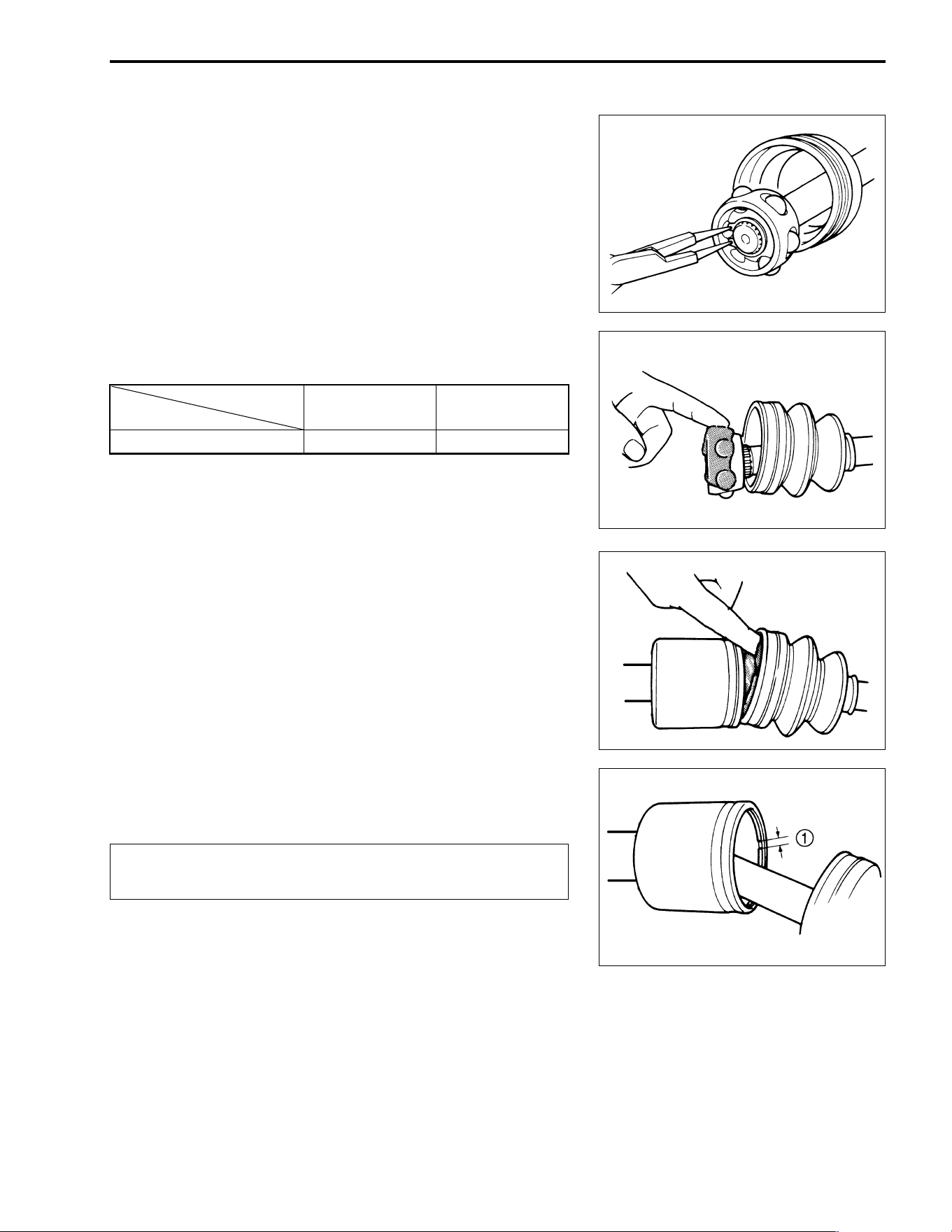
CHASSIS 7-17
• Install the snap ring to the cage.
• Apply grease to the entire surface of the cage and the inside
of the outer race.
NOTE:
The tube of joint grease is included in the wheel side boot set or
wheel side joint assembly of spare parts.
• Insert the cage into the outer race and fit a stopper ring in the
groove of the outer race.
$
Position
Grease
Wheel side Differential side
Quantity 40 g (1.4 oz) 55 g (1.9 oz)
Locate the opening of the stopper ring
1 so that the
opening is not lined up with a ball.
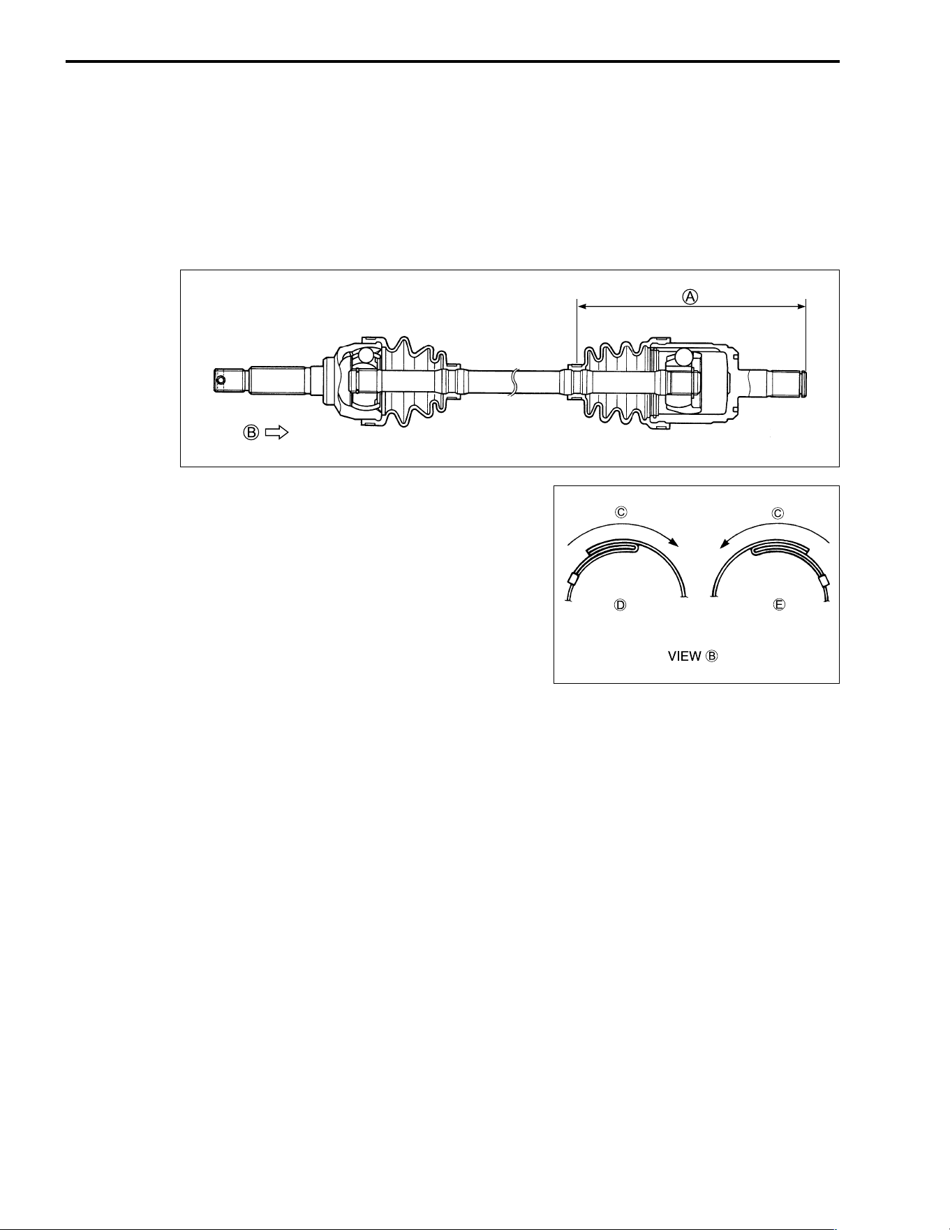
7-18 CHASSIS
• After fitting the boot on the outer race, insert a screw driver
into the boot on the outer race side and allow air to enter the
boot so that the air pressure in the boot becomes the same as
the atmospheric pressure at the positions indicated in the
illustration.
A 174 – 184 mm (6.9 – 7.2 in)
• Fix the boot on the outer race with a boot band, taking care
not to distort the boot.
C Rotation direction
D Right side
E Left side
REMOUNTING
• Install the front drive shaft. (!4-16)
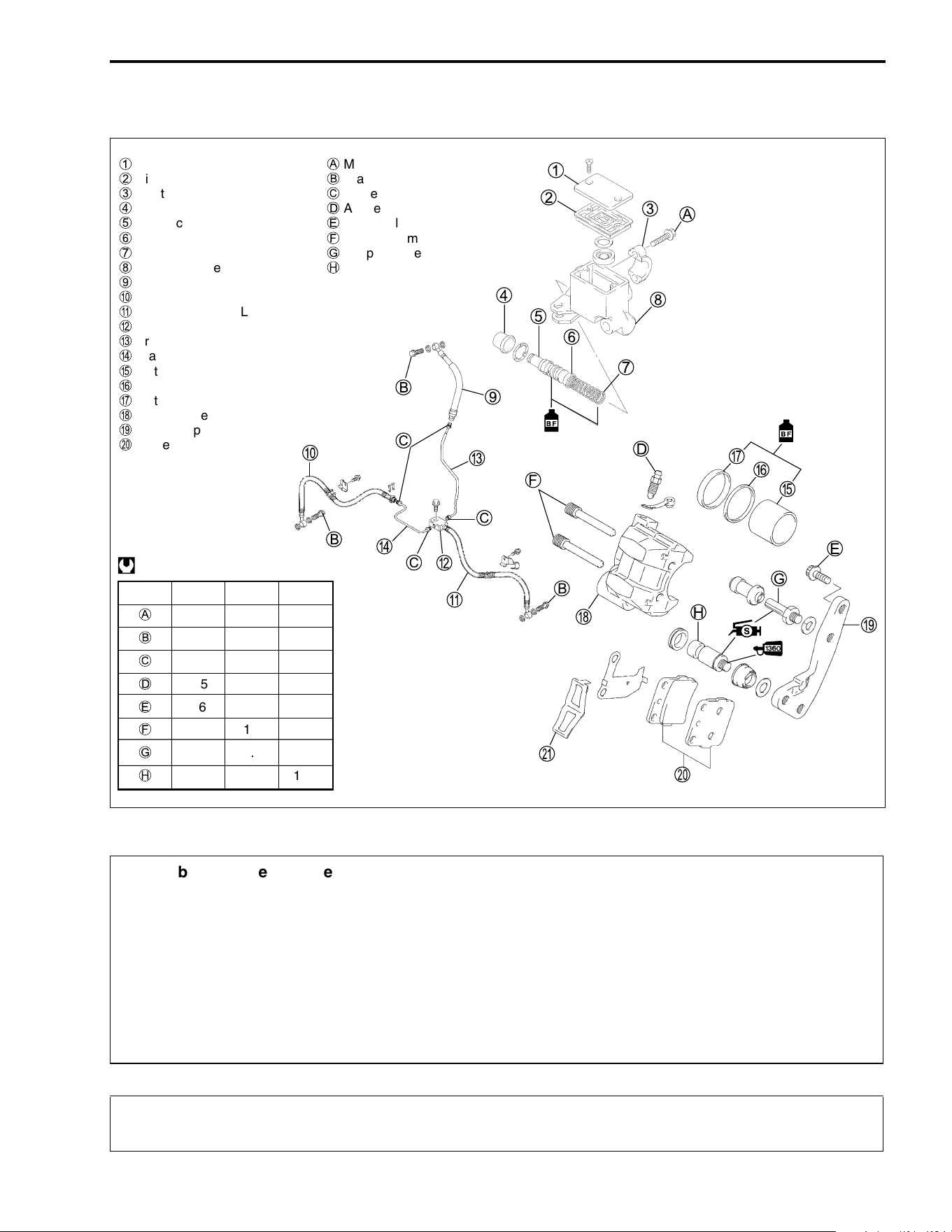
CHASSIS 7-19
FRONT BRAKE
CONSTRUCTION
&
$
1
Master cylinder reservior cap
A
Master cylinder mounting bolt
2
Diaphragm
B
Brake hose union bolt
3
Master cylinder clamp
C
Brake pipe nut
4
Boot
D
Air bleeder valve
5
Piston/cup set
E
Brake caliper mounting bolt
6
Cup
F
Brake pad mounting pin
7
Spring
G
Caliper holder pin
8
Master cylinder
H
Caliper holder pin
9
Brake hose No.1
0
Brake hose No.2, RH
A
Brake hose No.2, LH
B
Brake pipe joint
C
Brake pipe, No.1
D
Brake pipe, No.2
E
Piston
F
Dust seal
G
Piston seal
H
Brake caliper
I
Brake caliper holder
J
Brake pad
ITEM N·m kgf-m lb-ft
A
10 1.0 7.0
B
23 2.3 16.5
C
16 1.6 11.5
D
7.5 0.75 5.5
E
26 2.6 19.0
F
18 1.8 13.0
G
18 1.8 13.0
H
23 2.3 16.5
@
* This brake system is filled with an ethylene glycol-based DOT 4 brake fluid. Do not use or mix
different types of fluid, such as silicone-based or petroleum-based brake fluids.
* Do not use any brake fluid taken from old, used or unsealed containers. Never reuse brake
fluid left over from the last servicing or which has been stored for a long periods of time.
* When storing brake fluid, seal the container completely and keep it away from children.
* When replenishing brake fluid, take care not to get dust into the fluid.
* When washing brake components, use new brake fluid. Never use cleaning solvent.
* A contaminated brake disc or brake pad reduces braking performance. Discard contaminated
pads and clean the brake disc with high quality brake cleaner or a neutral detergent.
Handle brake fluid with care: the fluid reacts chemically with paint, plastics, rubber materials
etc. and will damage them severly.
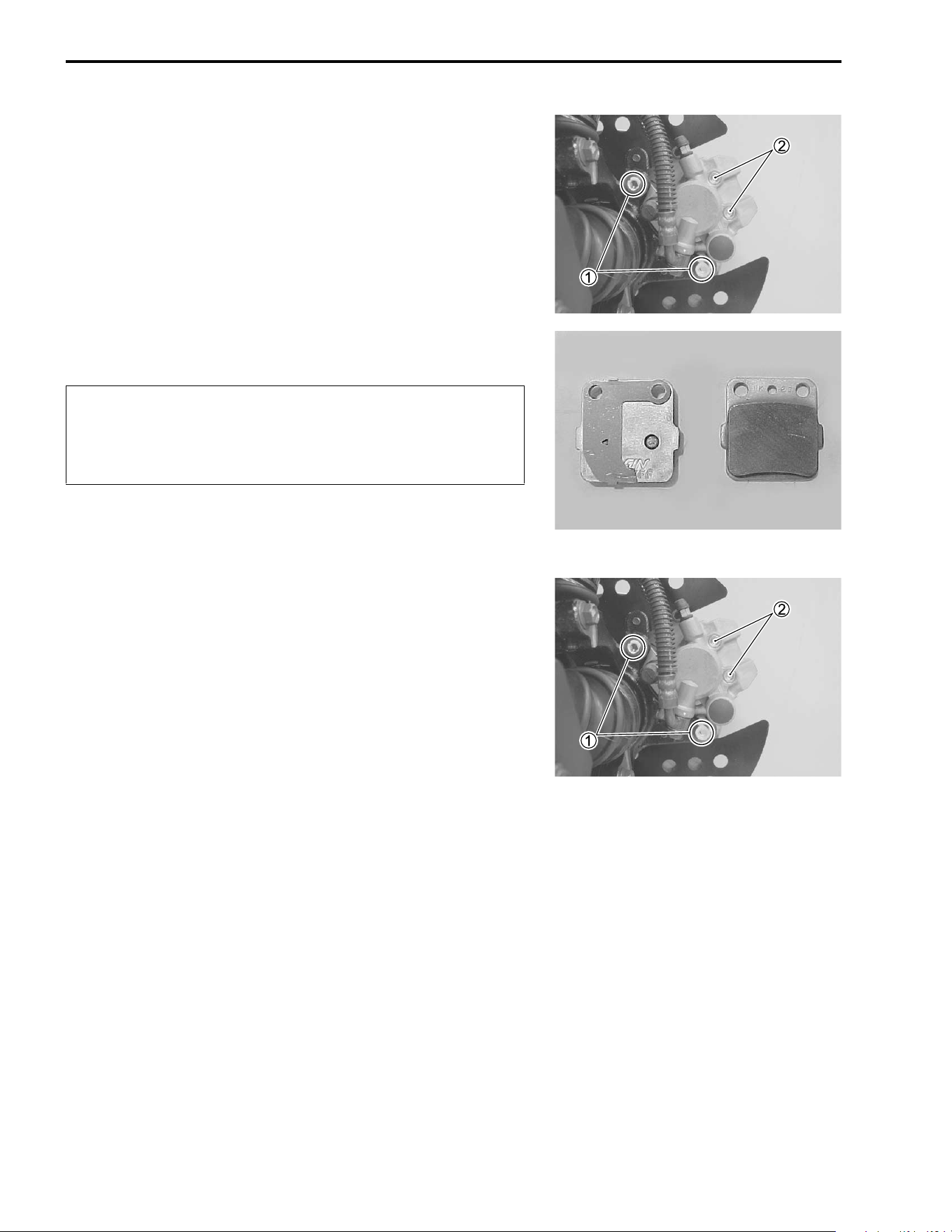
7-20 CHASSIS
BRAKE PAD REPLACEMENT
• Remove the front wheel. (!7-11)
• Remove the brake caliper mounting bolts
1 and brake pad
mounting pins
2.
• Remove the brake pads.
$
• Install the new brake pads.
NOTE:
The shim must be installed to the caliper piston side pad.
• Tighten the brake pad mounting pins
2 and brake caliper
mounting bolts
1 to the specified torque.
# Brake pad mounting pin: 18 N·m (1.8 kgf-m, 13.0 lb-ft)
Brake caliper mounting bolt:
26 N·m (2.6 kgf-m, 19.0 lb-ft)
NOTE:
After replacing the brake pads, pump the brake lever a few times
to check for proper brake operation and then check the brake
fluid level.
* Do not operate the brake lever during or after brake
pad removal.
* Replace the brake pads as a set, otherwise braking
performance will be adversely affected.
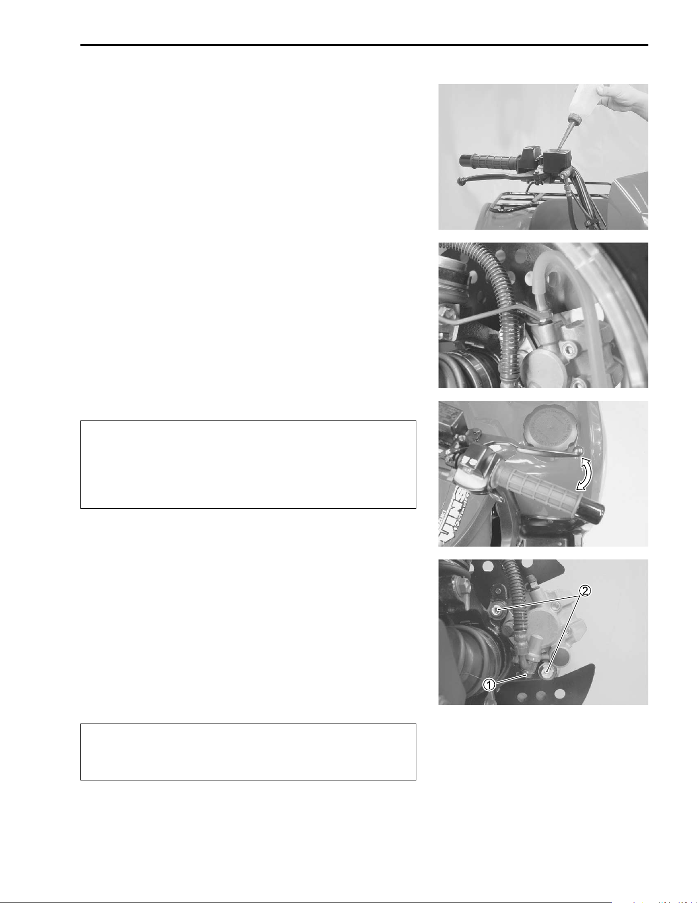
CHASSIS 7-21
BRAKE FLUID REPLACEMENT
• Place the vehicle on a level surface and keep the handlebar
straight.
• Remove the master cylinder reservoir cap and diaphragm.
• Suck up the old brake fluid as much as possible.
• Fill the reservoir with new brake fluid.
' Specification and classification: DOT 4
• Connect a clear hose to the air bleeder valve and insert the
other end of the hose into a receptacle.
• Loosen the air bleeder valve and pump the brake lever until
the old brake fluid is completely out of the brake system.
• Close the air bleeder valve and disconnect the clear hose. Fill
the reservoir with new brake fluid to the upper end of the
inspection window.
$
BRAKE CALIPER REMOVAL AND
DISASSEMBLY
• Remove the front wheel. (!7-11)
• Disconnect the brake hose from the brake caliper by remov-
ing the brake hose union bolt
1 and allow the brake fluid to
drain into a suitable receptacle.
• Remove the brake caliper by removing the brake caliper
mounting bolts
2.
• Remove the brake pads. (!7-20)
&
* Never reuse the brake fluid left over from previous
servicing and which has been stored for long peri-
ods of time.
* Bleed air from the brake system.
(!2-17)
Brake fluid, if it leaks, will interfere with safe running
and discolor painted surfaces. Check the brake hose
and hose joints for cracks and oil leakage.
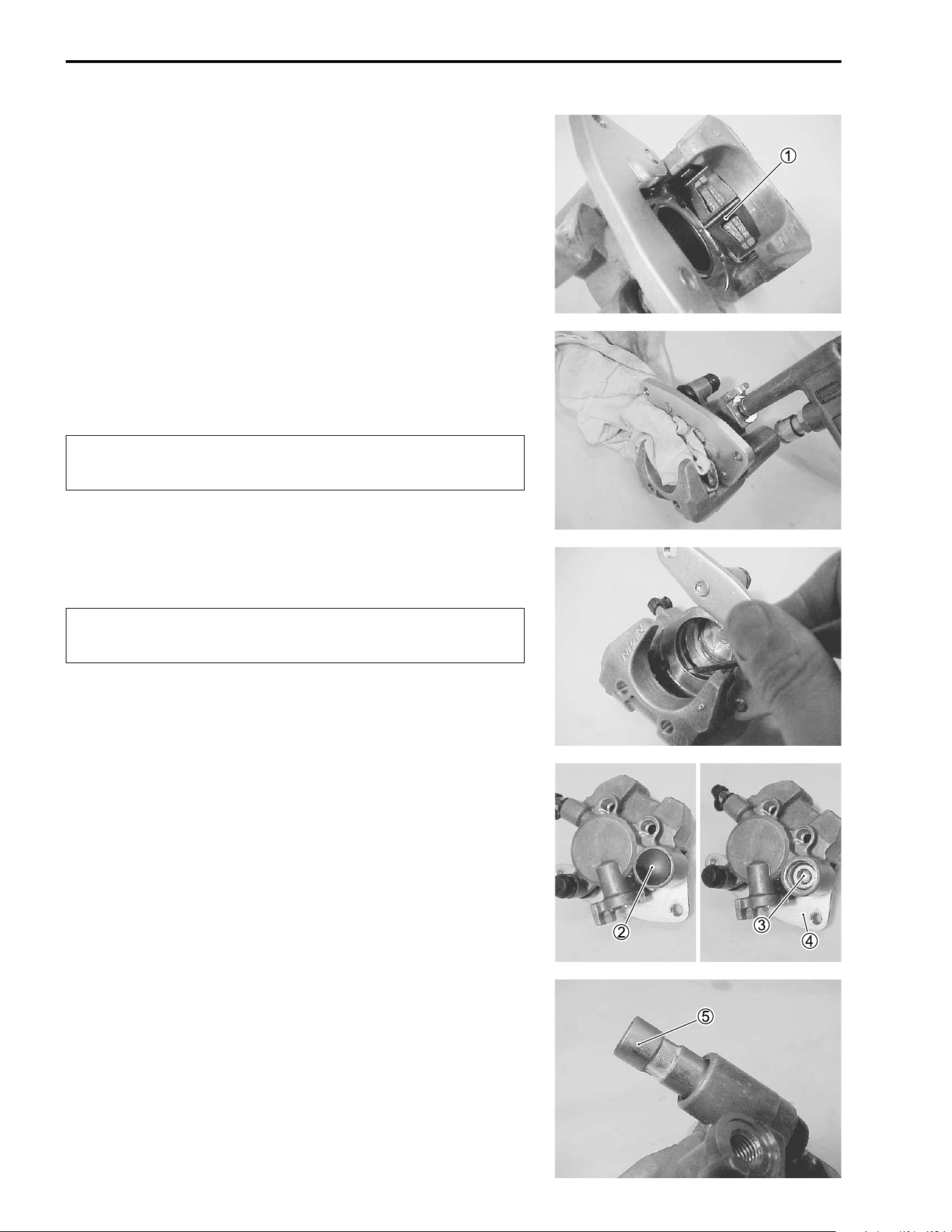
7-22 CHASSIS
• Remove the spring
1.
• Place a rag over the brake caliper pistons to prevent them
from popping out and then force out the pistons using com-
pressed air.
$
• Remove the dust seals and piston seals.
$
• Remove the cap
2 and loosen the brake caliper holder pin
3.
• Remove the brake caliper holder
4.
• Remove the brake caliper holder pin
5.
Do not use high pressure air to prevent brake caliper
piston damage.
Do not reuse the dust seal and piston seal to prevent
fluid leakage.
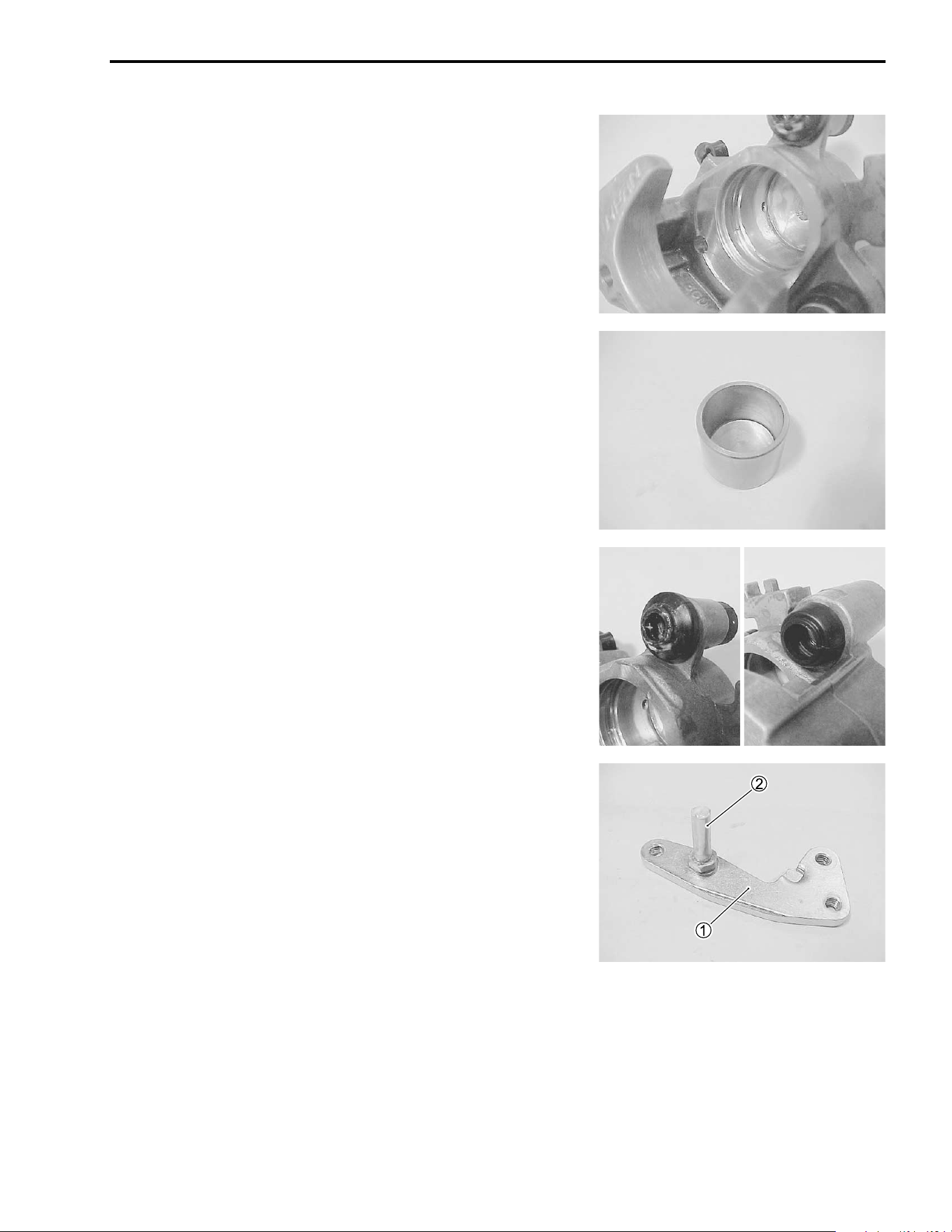
CHASSIS 7-23
BRAKE CALIPER INSPECTION
BRAKE CALIPER
Inspect the brake caliper cylinder wall for nicks, scratches or
other damage. If any damages are found, replace the brake cal-
iper with a new one.
BRAKE CALIPER PISTON
Inspect the brake caliper piston for any scratches or other dam-
age. If any damages are found, replace the piston with a new
one.
RUBBER PARTS
Replace the removed rubber parts with new ones.
CALIPER HOLDER
Inspect the caliper holder
1 and pin
2 for damage. If any dam-
ages are found, replace them with new ones.
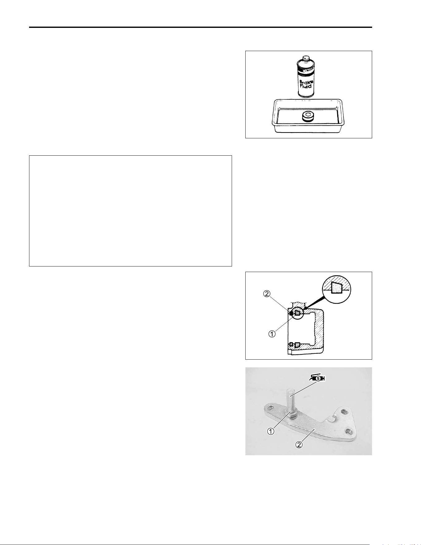
7-24 CHASSIS
BRAKE CALIPER REASSEMBLY AND
REMOUNTING
Reassemble and remount the brake caliper in the reverse order
of removal and disassembly. Pay attention to the following
points:
• Wash the caliper bores and pistons with the specified brake
fluid. Thoroughly wash the dust seal grooves and piston seal
grooves.
' Specification and classification: DOT 4
$
PISTON SEALS
• Install the piston seal
1 and dust seal
2 as shown.
BRAKE CALIPER HOLDER
• Tighten the pin
1 to the caliper holder
2 to the specified
torque.
# Caliper holder pin: 18 N·m (1.8 kgf-m, 13.0 lb-ft)
• Apply SUZUKI SILICON GREASE to the brake caliper holder
pin.
( 99000-25100: SUZUKI SILICONE GREASE
* Wash the brake caliper components with new brake
fluid before reassembly.
* Do not wipe the brake fluid off with a rag after wash-
ing the components.
* When washing the components, use the specified
brake fluid. Never use different types of fluid or
cleaning solvents such as gasoline, kerosine, etc.
* Replace the removed piston seals and dust seals
with new ones.
* Apply brake fluid to all of the seals, brake caliper
bores and pistons before reassembly.
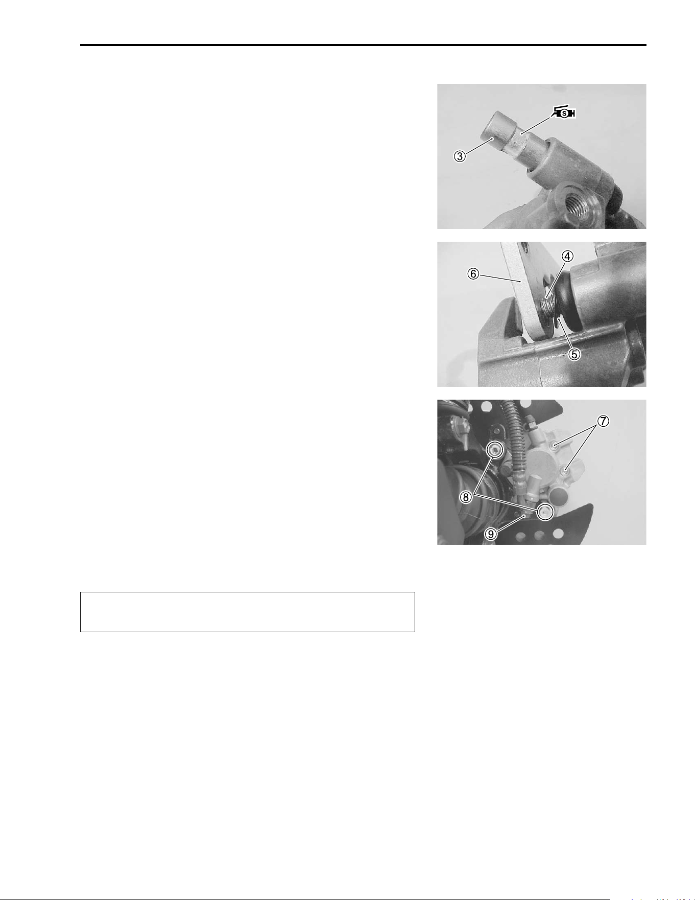
CHASSIS 7-25
• Apply SUZUKI SILICON GREASE to the pin
3.
( 99000-25100: SUZUKI SILICON GREASE
• Install the pin
4, washer
5 and caliper holder
6 to the cali-
per.
• Apply THREAD LOCK SUPER “1360” to the pin
4.
) 99000-32130: THREAD LOCK SUPER “1360”
• Tighten the pin
4 to the specified torque.
# Caliper holder pin: 23 N·m (2.3 kgf-m, 16.5 lb-ft)
• Install the pads to the caliper.
• Tighten the brake pad mounting pins
7, brake caliper mount-
ing bolts
8, and brake hose union bolt
9 to the specified
torque.
# Brake pad mounting pin: 18 N·m (1.8 kgf-m, 13.0 lb-ft)
Brake caliper mounting bolt:
26 N·m (2.6 kgf-m, 19.0 lb-ft)
Brake hose union bolt: 23 N·m (2.3 kgf-m, 16.5 lb-ft)
NOTE:
Before remounting the brake caliper, push the brake caliper pis-
tons all the way into the caliper.
$
Bleed air from the system after reassembling the
brake caliper. (!2-17)
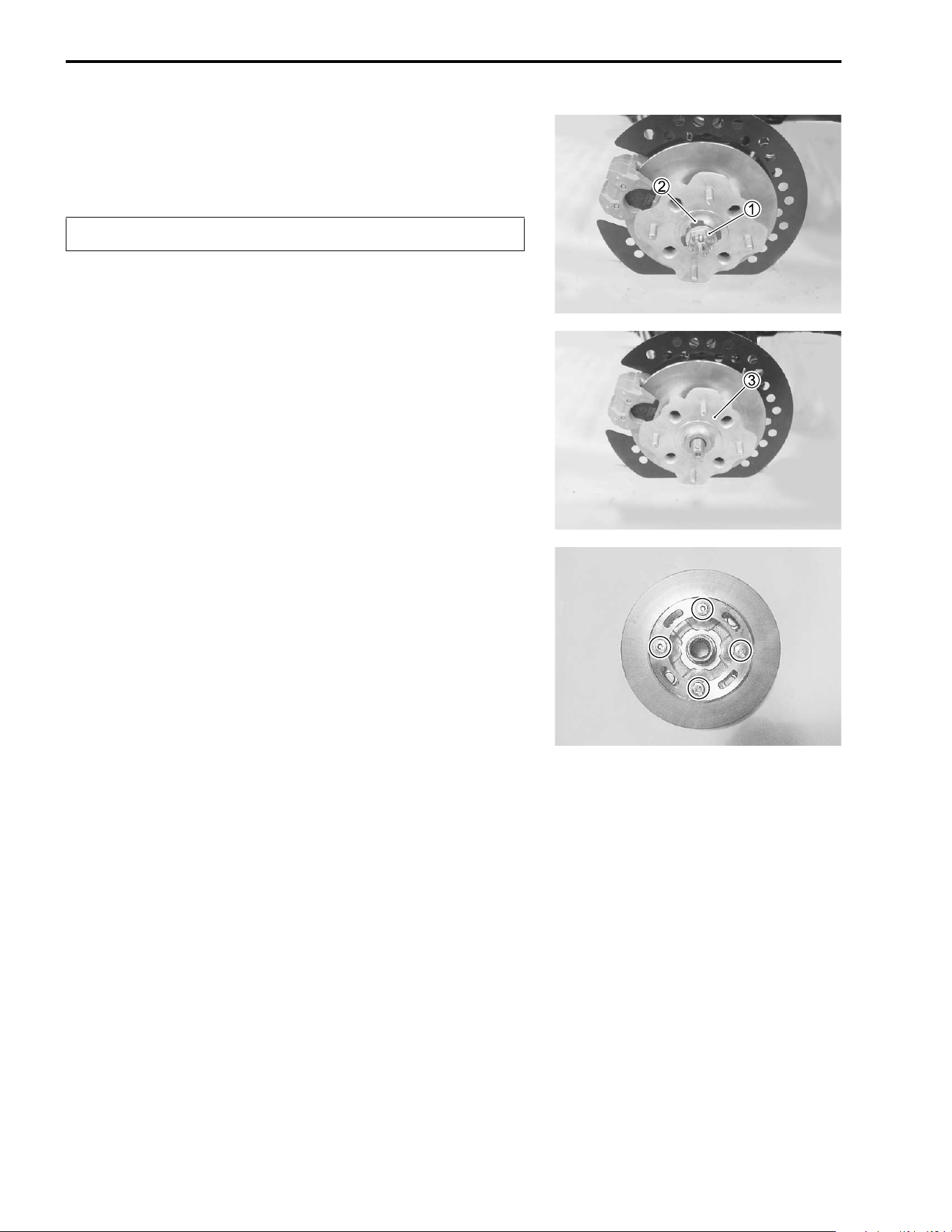
7-26 CHASSIS
BRAKE DISC REMOVAL AND DISASSEMBLY
• Remove the front wheel. (!7-11)
• Remove the cotter pin.
$
• Loosen the axle nut
1 by applying the front brake.
• Remove the axle nut
1 and spring washer
2.
• Remove the brake caliper. (!7-21)
• Remove the front wheel hub
3.
• Remove the brake disc.
Replace the removed cotter pin with a new one.
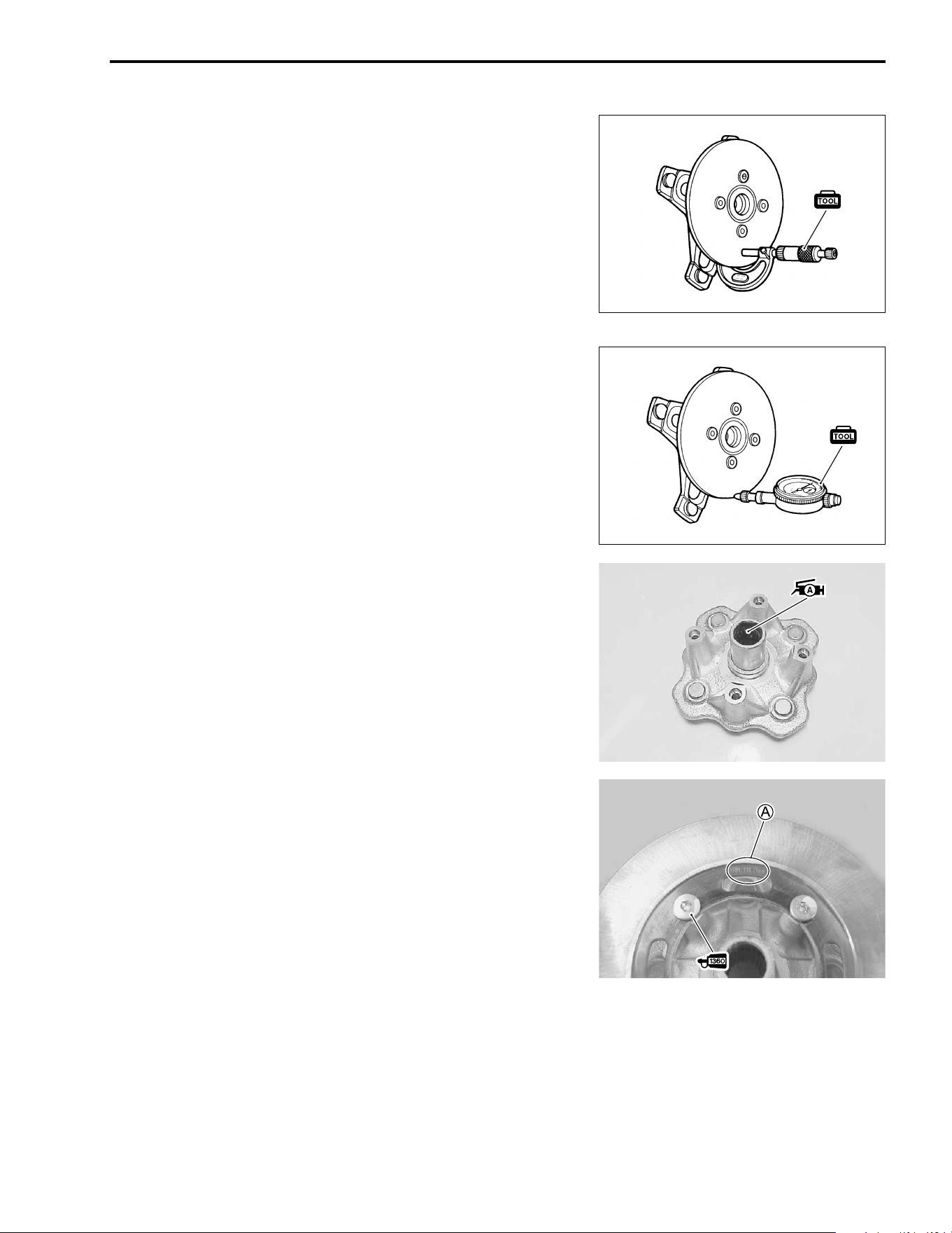
CHASSIS 7-27
BRAKE DISC INSPECTION
• Remove the front wheel. (!7-11)
Inspect the brake disc for cracks or damage and measure the
thickness using the micrometer. If any damages are found or if
the thickness is less than the service limit, replace the brake disc
with a new one.
* 09900-20205: Micrometer (0 – 25 mm)
% Brake disc thickness
Service Limit: 3.0 mm (0.12 in)
Measure the runout using the dial gauge. If the runout exceeds
the service limit, replace the brake disc with a new one.
* 09900-20607: Dial gauge (1/100 mm)
09900-20701: Magnetic stand
% Brake disc runout
Service Limit: 0.3 mm (0.012 in)
• If either measurement exceeds the service limit, replace the
brake disc with a new one.
BRAKE DISC REASSEMBLY AND
REMOUNTING
Reassemble and remount the brake disc in the reverse order of
removal and disassembly.
Pay attention to the following points:
• Apply SUZUKI SUPER GREASE “A” to the wheel hub spline.
+ 99000-25030: SUZUKI SUPER GREASE “A” (USA)
99000-25010: SUZUKI SUPER GREASE “A” (Others)
• Install the disc to the wheel hub with the punching letter
showed.
• Apply THREAD LOCK SUPER “1360” to the brake disc bolts
and tighten them to the specified torque.
) 99000-32130: THREAD LOCK SUPER “1360”
# Brake disc bolt: 23 N·m (2.3 kgf-m, 16.5 lb-ft)
NOTE:
Stamped mark
A on the brake disc must face outside.
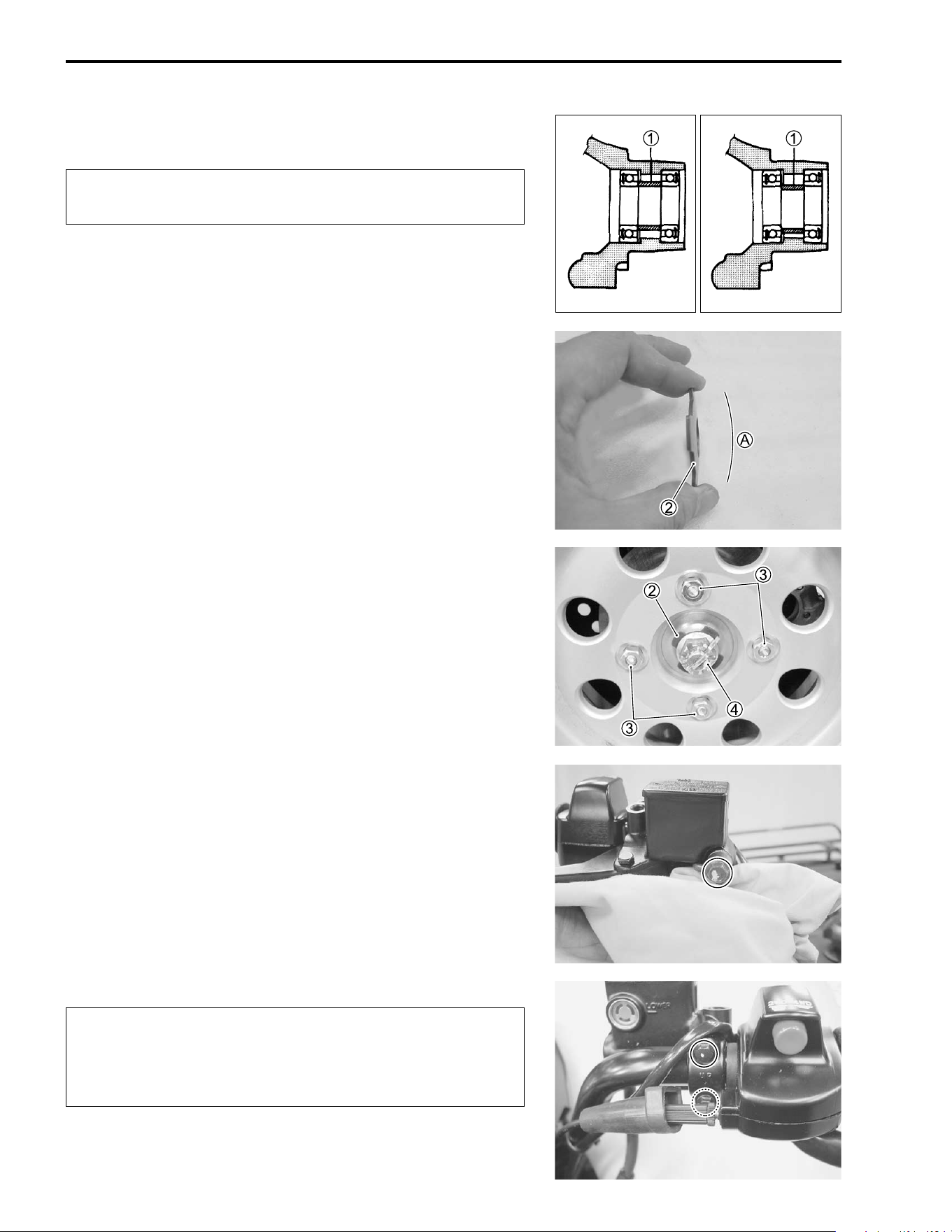
7-28 CHASSIS
• Install the wheel hub.
$
• Install the front caliper. (!7-25)
• Install the spring washer
2 as its convex side
A faces to the
front hub nut.
• Tighten the front wheel set nuts
3, and hub nut
4 to the
specified torque.
# Front wheel set nut: 50 N·m (5.0 kgf-m, 36.0 lb-ft)
Front hub nut: 110 N·m (11.0 kgf-m, 79.5 lb-ft)
NOTE:
* First, remount the front wheels and lower the jack, and then
tighten the front hub nut to specified torque.
* After installing the front hub nut, insert a new cotter pin into the
driver shaft.
MASTER CYLINDER REMOVAL AND
DISASSEMBLY
• Place a rag underneath the brake hose union bolt on the mas-
ter cylinder to catch any spilt brake fluid. Remove the brake
hose union bolt and disconnect the brake hose.
$
• Remove the master cylinder assembly.
When installing the wheel hub, make sure the spacer
1 is properly positioned.
INCORRECT
CORRECT
Immediately wipe off any brake fluid contacting any
part of the vehicle. The brake fluid reacts chemically
with paint, plastics, rubber materials, etc., and will
damage them severely.
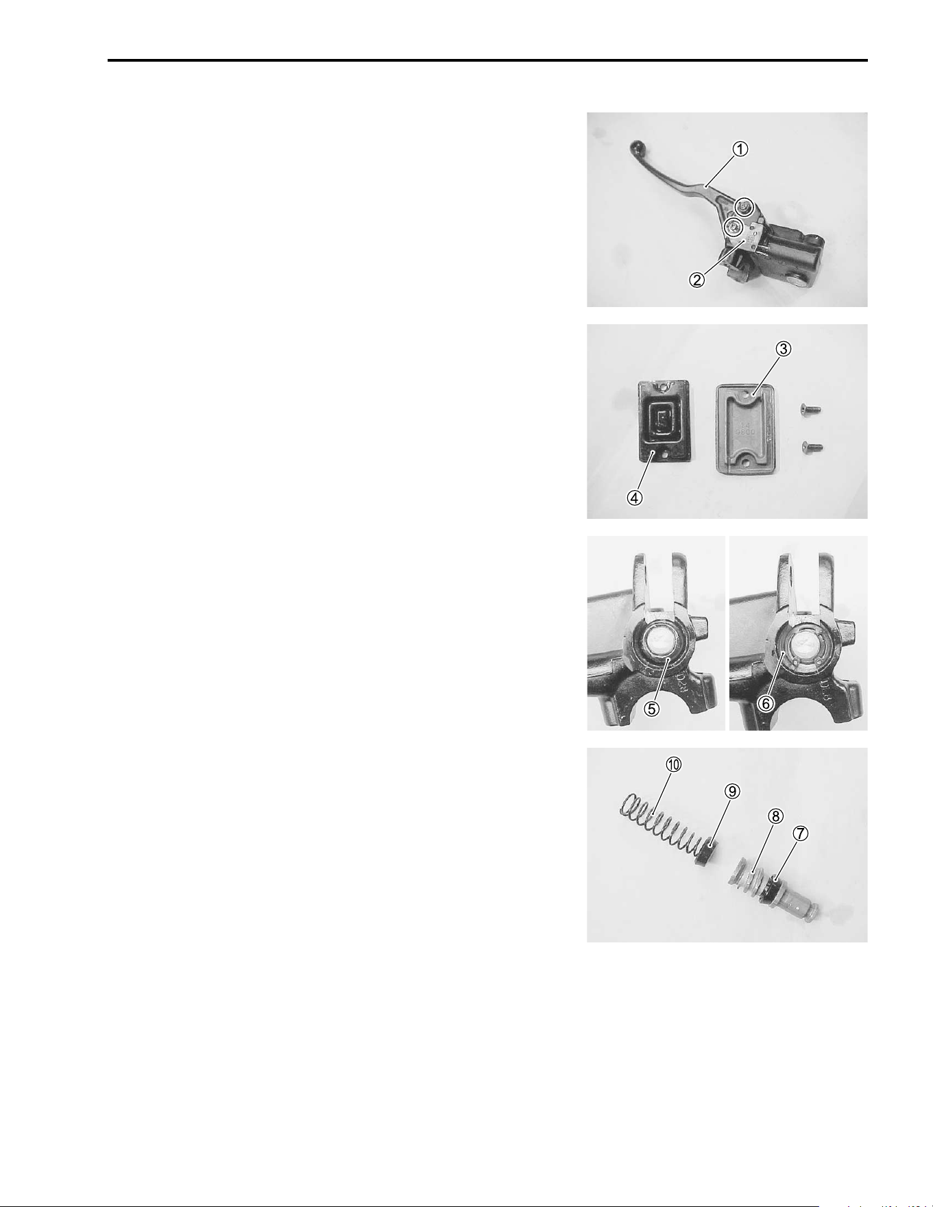
CHASSIS 7-29
• Remove the brake lever
1 and brake switch
2.
• Remove the reservoir cap
3 and diaphragm
4.
• Drain the brake fluid.
• Pull the dust boot
5 out and remove the circlip
6.
• Remove the piston/secondary cup, primary cup and spring.
7 Secondary cup
8 Piston
9 Primary cup
0 Spring
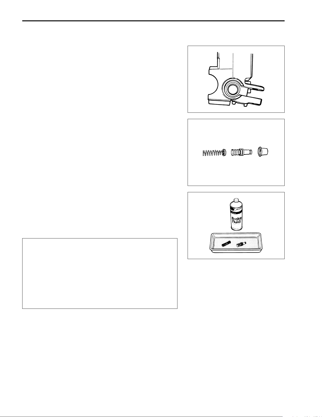
7-30 CHASSIS
MASTER CYLINDER INSPECTION
MASTER CYLINDER
Inspect the master cylinder bore for any scratches or damage. If
any damages are found, replace the master cylinder with a new
one.
PISTON AND RUBBER PARTS
Inspect the piston surface, primary cup, secondary cup and dust
seal for any scratches, wear or damage. If any damages are
found, replace the piston set with a new one.
MASTER CYLINDER REASSEMBLY AND
REMOUNTING
Reassemble and remount the master cylinder in the reverse
order of removal and disassembly. Pay attention to the following
points:
$
' Specification and classification: DOT 4
* Wash the master cylinder components with new
brake fluid before reassembly.
* Do not wipe the brake fluid off with a rag after wash-
ing the components.
* When washing the components, use the specified
brake fluid. Never use different types of fluid or
cleaning solvents such as gasoline, kerosine, etc.
* Apply brake fluid to the master cylinder bore and all
the component to be inserted to the bore.
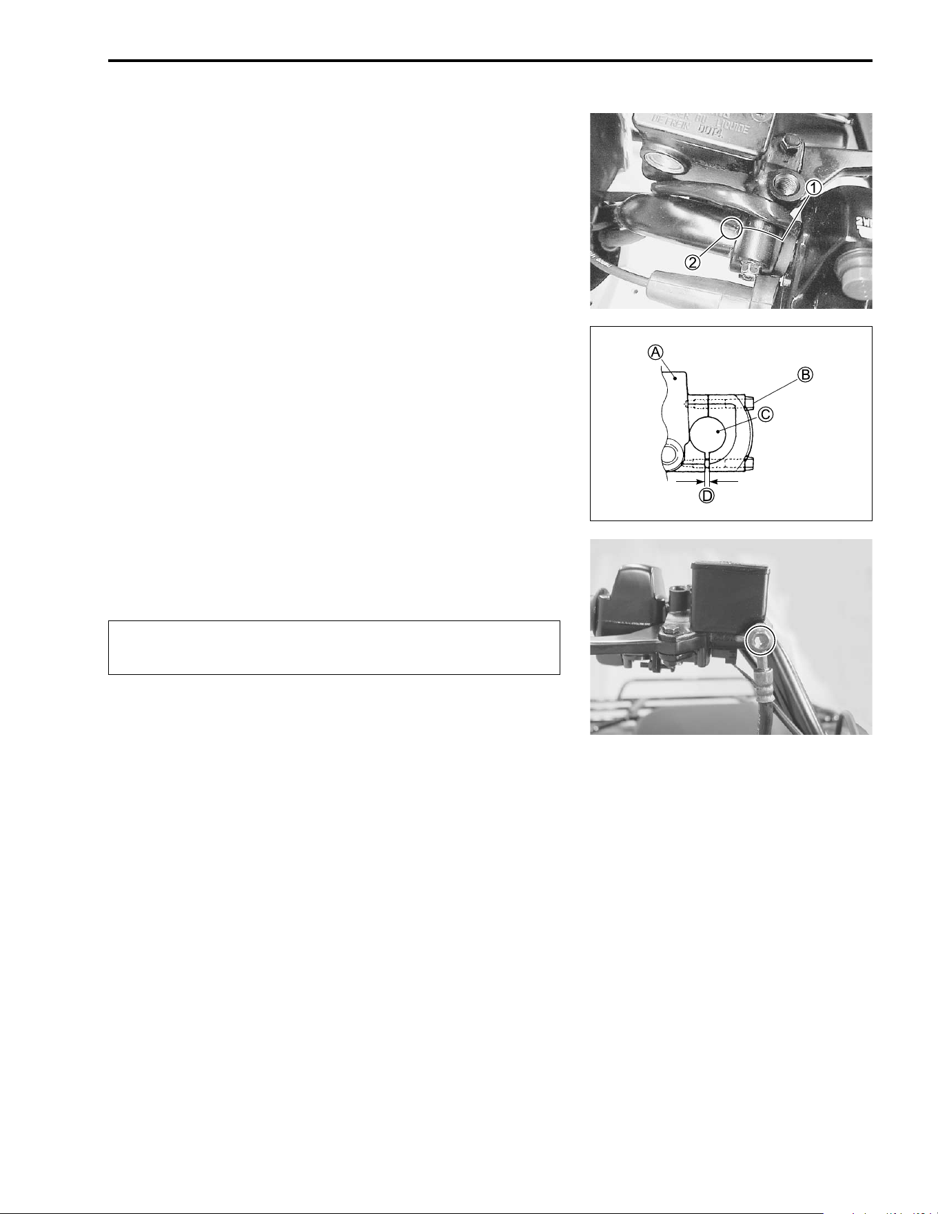
CHASSIS 7-31
When remounting the master cylinder on the handlebars, align
the master cylinder holder's mating surface
1 with the punch
mark
2 on the handlebar and tighten the upper clamp bolt first.
# Master cylinder clamp bolt: 10 N·m (1.0 kgf-m, 7.0 lb-ft)
A Master cylinder
B Master cylinder upper clamp bolt
C Handlebar
D Clearance
• Tighten the brake hose union bolt to the specified torque.
# Brake hose union bolt: 23 N·m (2.3 kgf-m, 16.5 lb-ft)
$
Bleed air from the brake system after reassembling
the master cylinder. (!2-17)
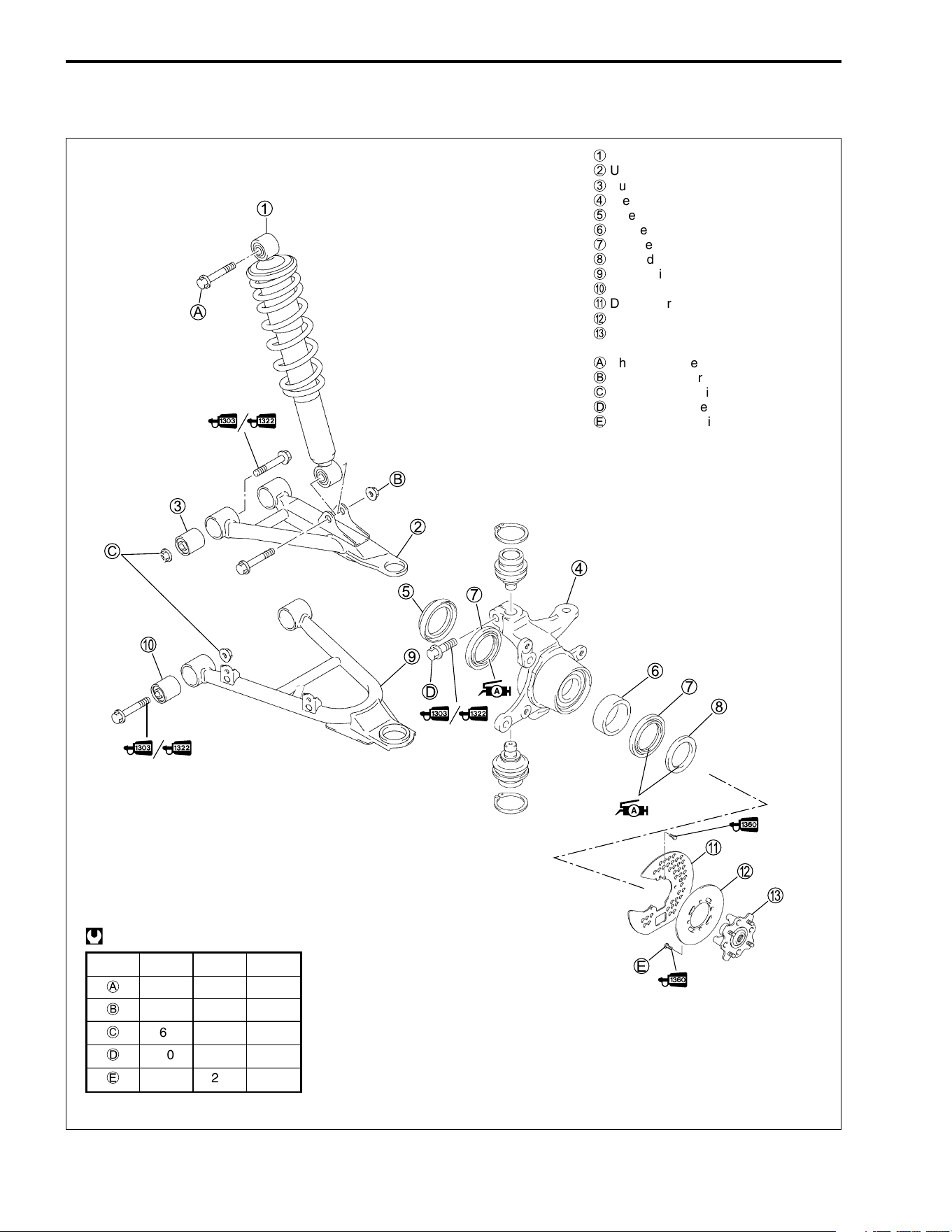
7-32 CHASSIS
FRONT SUSPENSION
CONSTRUCTION
1
Front shock absorber
2
Upper wishbone arm
3
Bushing
4
Steering knuckle
5
Inner dust seal
6
Spacer
7
Hub bearing
8
Outer dust seal
9
Lower wishbone arm
0
Bushing
A
Disc cover
B
Front disc
C
Front hub
A
Shock absorber mounting upper bolt
B
Shock absorber mounting lower nut
C
Wishbone arm pivot nut
D
Steering knuckle pinch bolt
E
Front disc mounting bolt
ITEM N·m kgf-m lb-ft
A
55 5.5 40.0
B
60 6.0 43.5
C
65 6.5 47.0
D
50 5.0 36.0
E
23 2.3 16.5
@
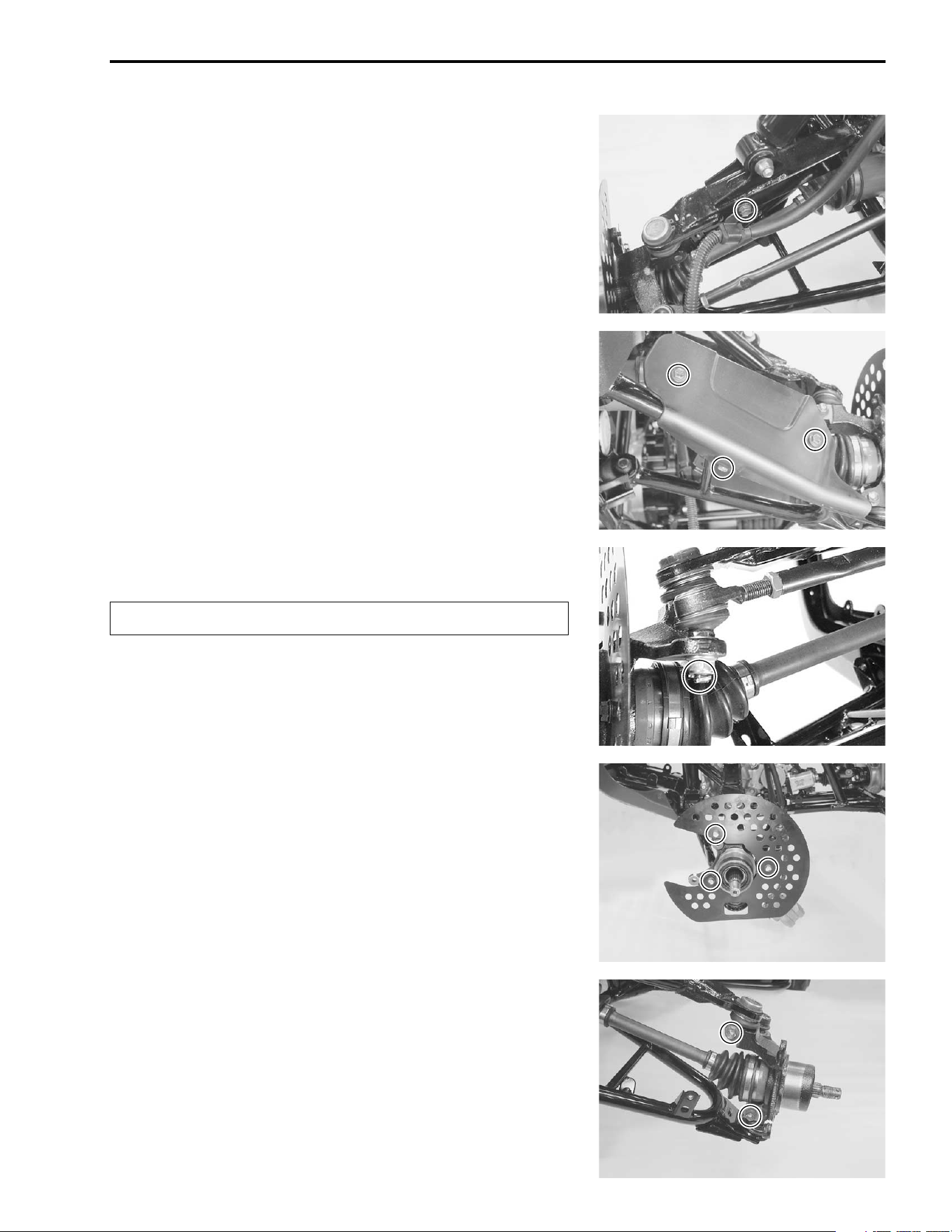
CHASSIS 7-33
REMOVAL AND DISASSEMBLY
• Remove the wheel hub with brake disc. (!7-26)
• Remove the brake hose clamp.
• Remove the drive shaft cover.
• Remove the cotter pin and tie rod end nut.
$
• Remove the front disc cover.
• Loosen the steering knuckle pinch bolts and remove the
steering knuckle.
Replace the removed cotter pin with a new one.
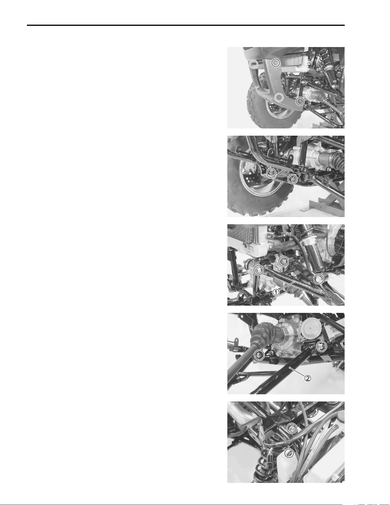
7-34 CHASSIS
• Remove the front grip lower cover. (!7-4)
• Remove the front grip mounting bolts for helping to remove
the lower wishbone arm mounting bolt.
• Loosen the upper wishbone arm pivot bolts/nuts and lower
shock absorber mounting bolt/nut.
• Remove the upper wishbone
1.
• Loosen the lower wishbone arm pivot bolts/nuts.
• Remove the lower wishbone
2.
• Loosen the engine coolant reservoir mounting bolt.
• Remove the upper shock absorber mounting bolt.
• Remove the shock absorber.
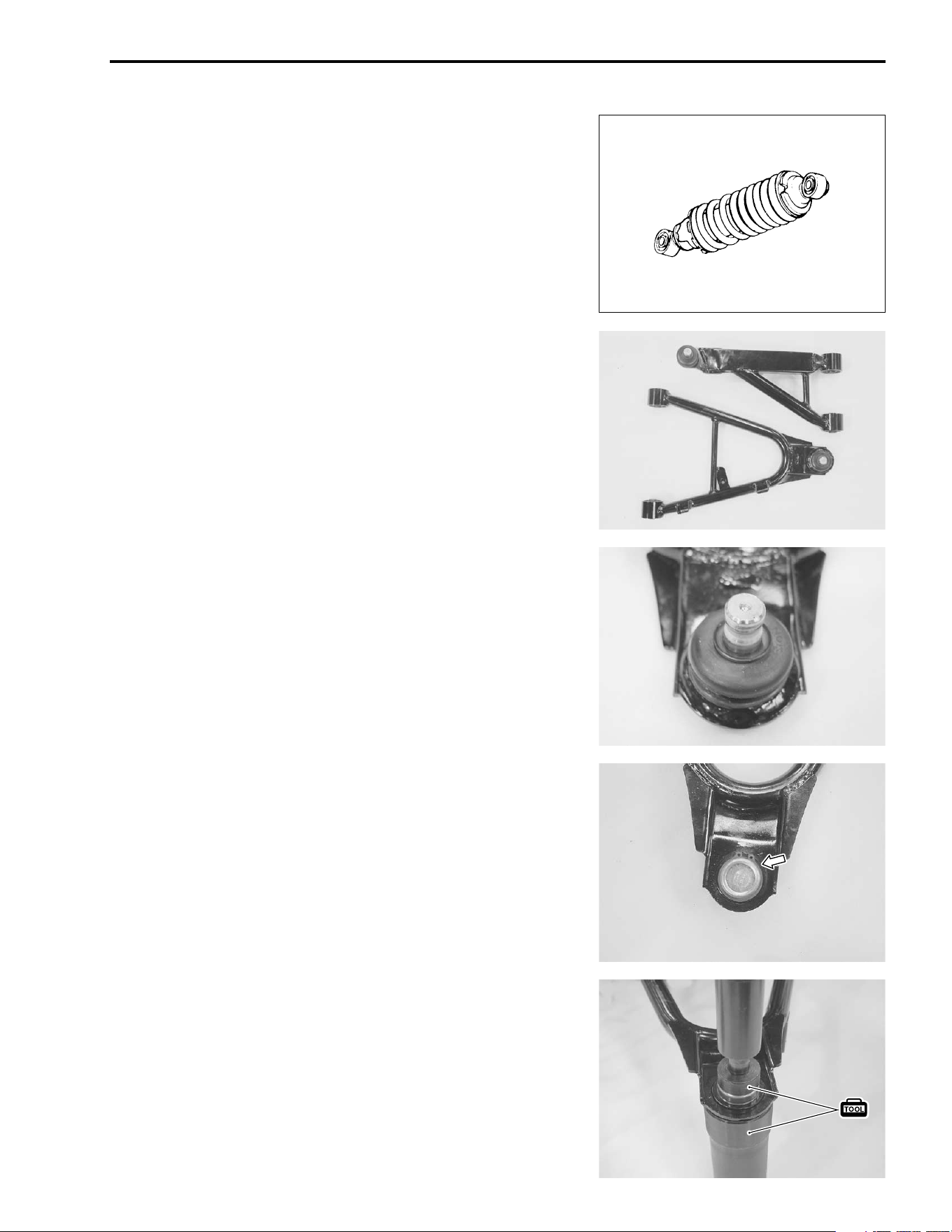
CHASSIS 7-35
INSPECTION
FRONT SHOCK ABSORBER
Inspect the shock absorber for oil leakage or damage. If any
damages are found, replace the front shock absorber with a new
one.
WISHBONE ARM
Inspect the wishbone arms for damage. If any damages are
found, replace the wishbone arm with a new one.
KNUCKLE END
Inspect the knuckle end boot for wear or damage. If any dam-
ages are found, replace the knuckle end with a new one.
• Remove the snap ring.
• Remove the knuckle end by using the special tools.
* 09913-70210: Bearing installer set
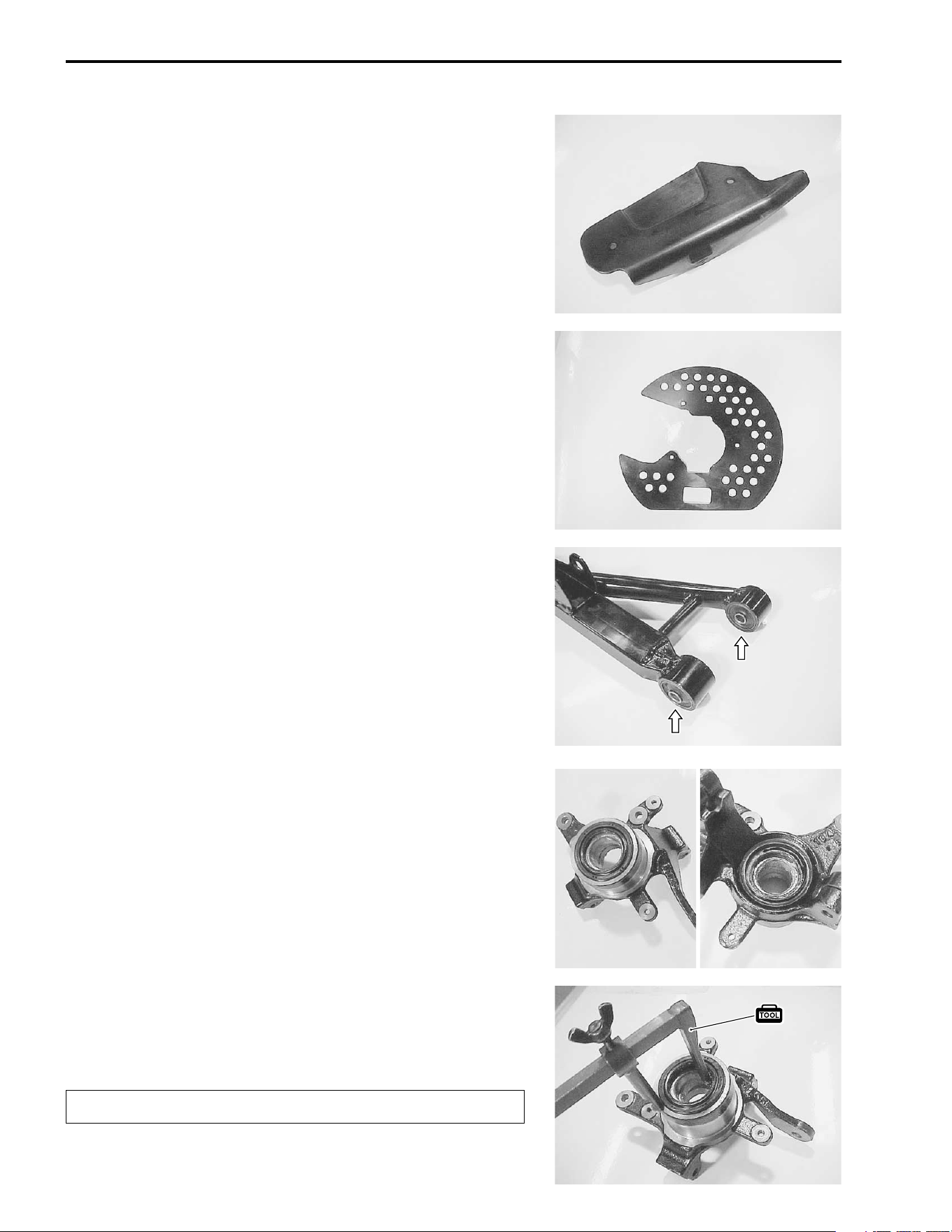
7-36 CHASSIS
DRIVE SHAFT COVER
Inspect the drive shaft cover for damage. If any damages are
found, replace the drive shaft cover with a new one.
BRAKE DISC COVER
Inspect the brake disc cover for damage. If any damages are
found, replace the brake disc cover with a new one.
BUSHING
Inspect the rubber bushing (shock absorber/wishbone arm) for
wear or other damage. If any damages are found, replace the
bushing with a new one.
DUST SEAL
Inspect the dust seal lips for wear or damage. If any damages
are found, replace the dust seal with a new one.
• Remove the steering knuckle dust seals by using the special
tool.
* 09913-50121: Oil seal remover
$
Replace the removed dust seal with a new one.
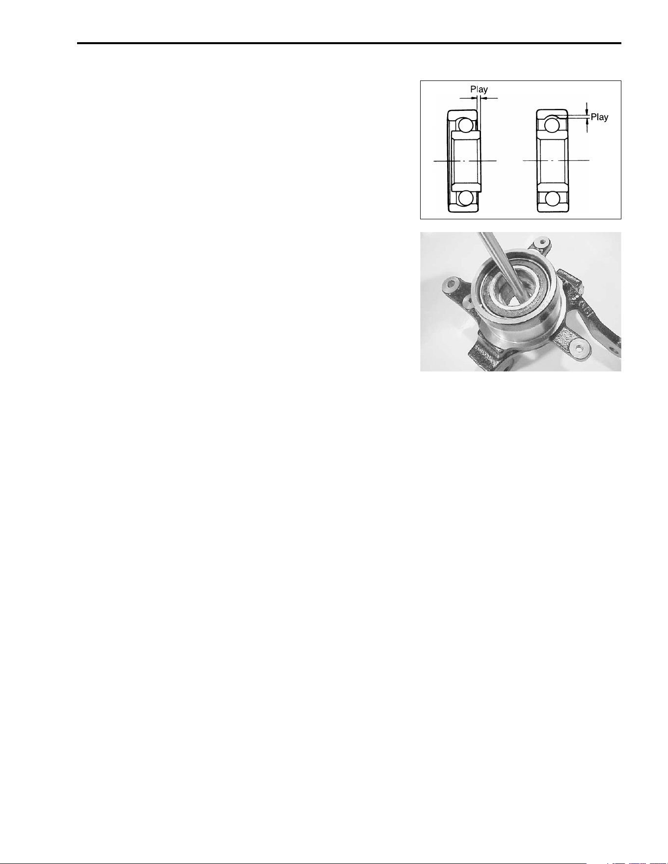
CHASSIS 7-37
HUB BEARINGS
Inspect the inner race play of the hub bearing by hand while it is
in the steering knuckle.
Rotate the inner race by hand to inspect for abnormal noise and
smooth rotation. If there is anything unusual, replace the bearing
with a new one.
NOTE:
Make sure to check each bearing in the same manner.
• Remove the hub bearings using the appropriate bar.
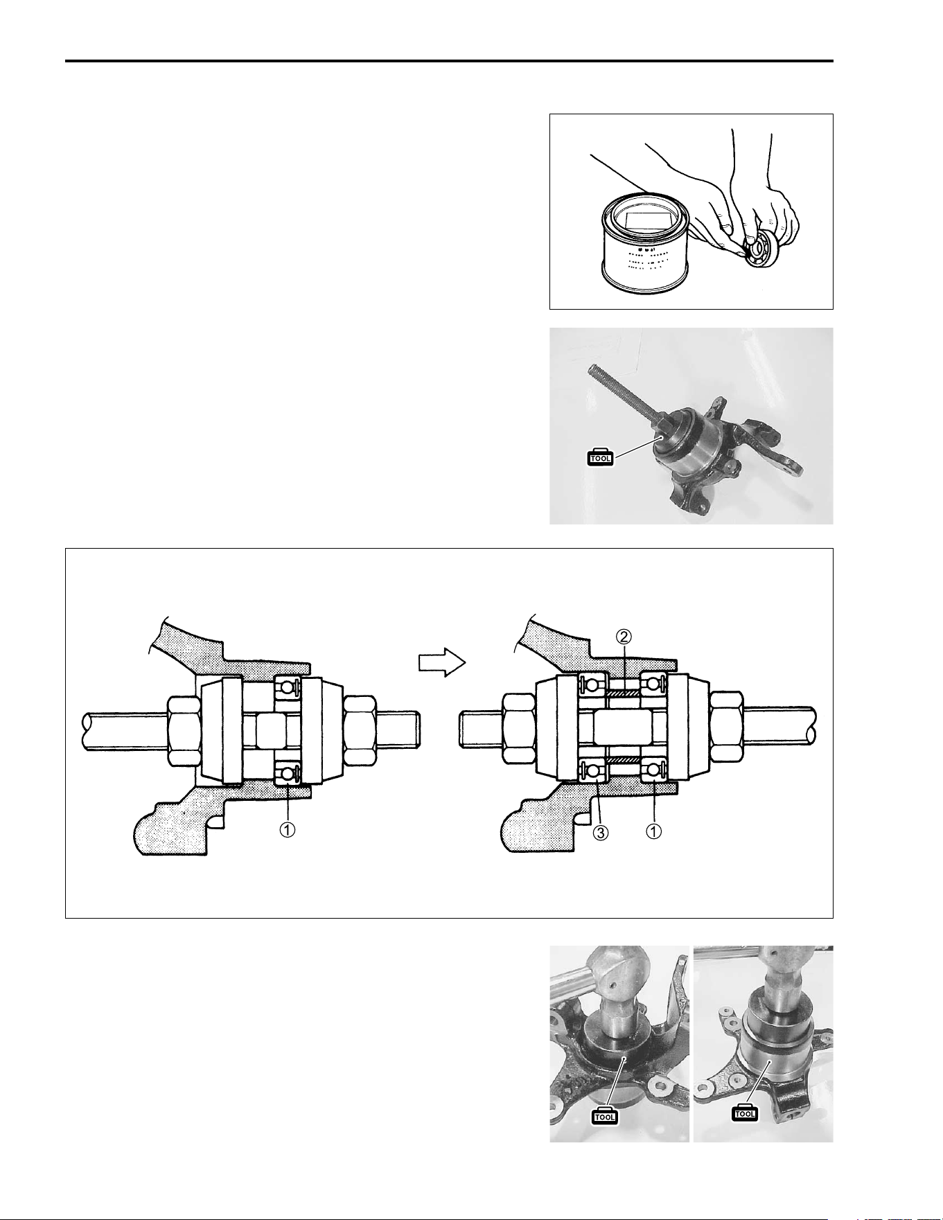
7-38 CHASSIS
REASSEMBLY AND REMOUNTING
Reassemble and remount the front suspension in the reverse
order of removal and disassembly. Pay attention to the following
points:
• Apply SUZUKI SUPER GREASE “A” to the hub bearings and
the lip of the dust seals before installing them.
+ 99000-25030: SUZUKI SUPER GREASE “A” (USA)
99000-25010: SUZUKI SUPER GREASE “A” (Others)
• Install the hub bearings using the special tool.
* 09924-84510: Bearing installer set
NOTE:
Install the outer bearing
1, the spacer
2, and then the inner
bearing
3. Make sure the sealed side of the bearing faces out-
ward.
• Install the steering knuckle dust seal using the special tool.
* 09913-70210: Bearing installer set
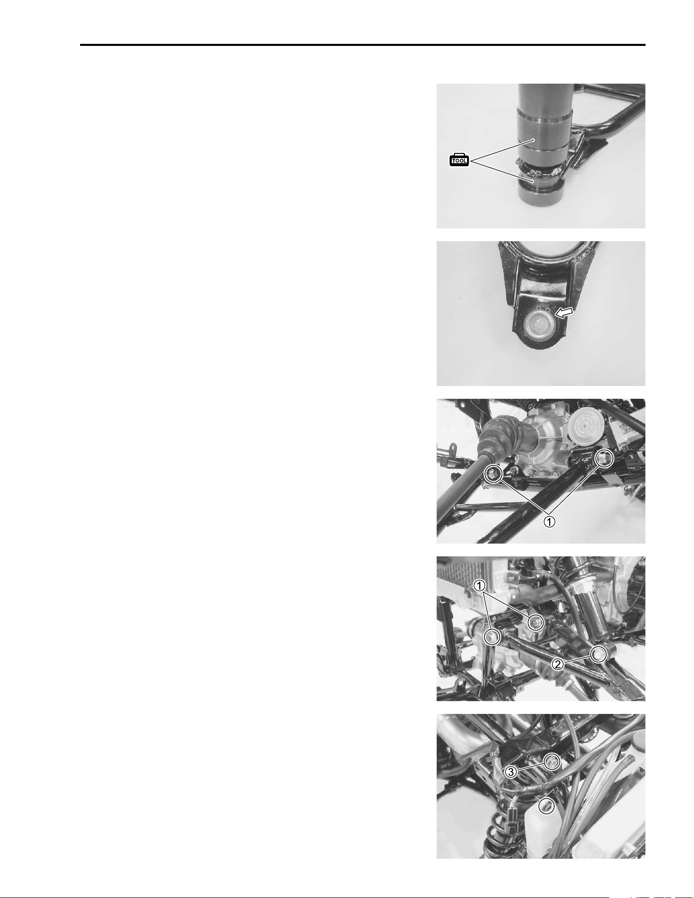
CHASSIS 7-39
• Install the knuckle end to the wishbone arm by using the spe-
cial tools.
* 09913-70210: Bearing installer set
• Install the new snap ring securely.
• Apply THREAD LOCK SUPER “1303” or “1322” to the wish-
bone arm pivot bolts, and then tighten the nuts
1 to the spec-
ified torque.
, 99000-32030: THREAD LOCK SUPER “1303” (USA)
- 99000-32110: THREAD LOCK SUPER “1322” (Others)
# Wishbone arm pivot nut: 65 N·m (6.5 kgf-m, 47.0 lb-ft)
• Tighten the shock absorber mounting lower bolt/nut
2 to the
specified torque.
# Shock absorber mounting lower nut:
60 N·m (6.0 kgf-m, 43.5 lb-ft)
• Tighten the shock absorber mounting upper bolt
3.
• Tighten the engine coolant reservoir mounting bolt.
# Shock absorber mounting upper bolt:
55 N·m (5.5 kgf-m, 40.0 lb-ft)
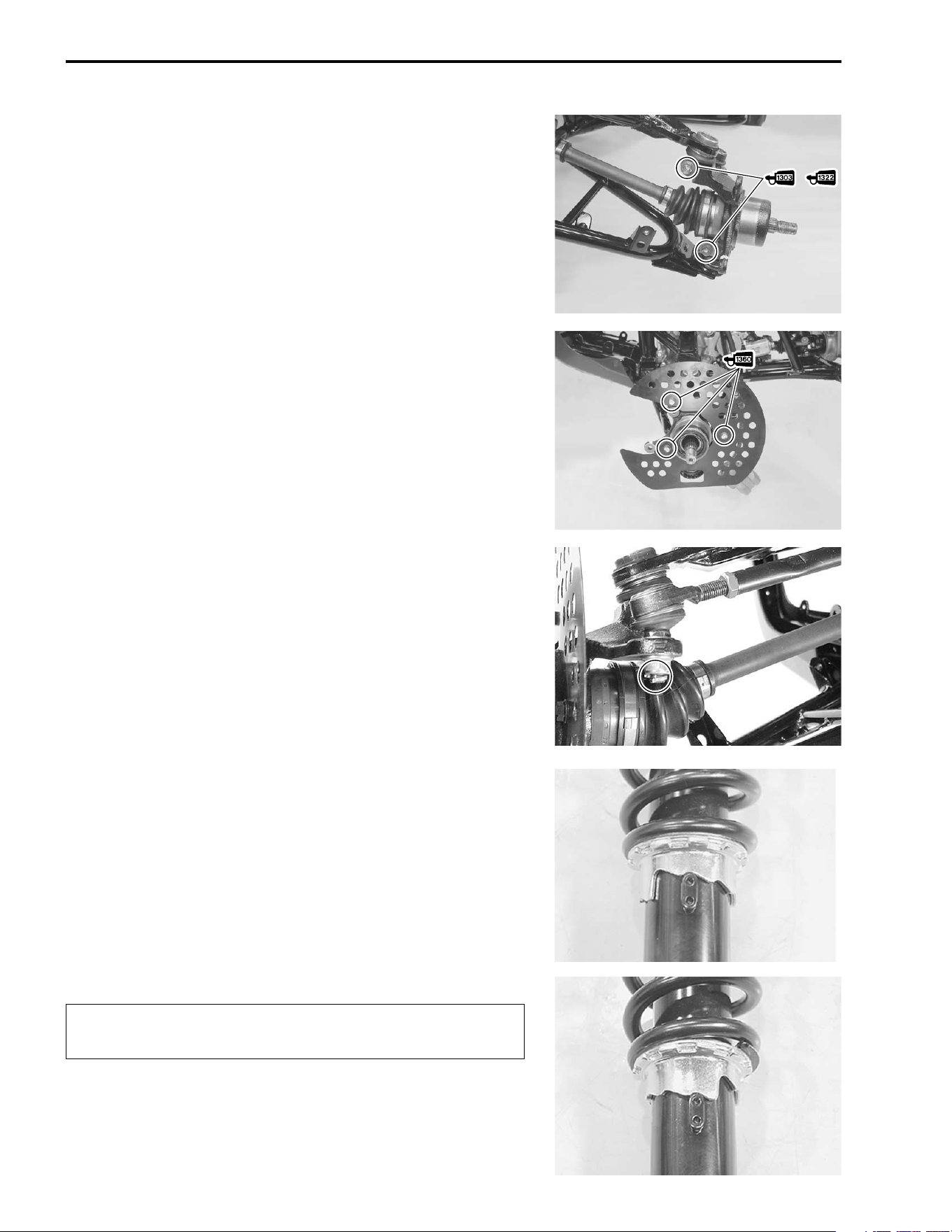
7-40 CHASSIS
• Apply THREAD LOCK SUPER “1303” or “1322” to the steer-
ing knuckle pinch bolts, and then tighten them to the specified
torque.
, 99000-32030: THREAD LOCK SUPER “1303” (USA)
- 99000-32110: THREAD LOCK SUPER “1322” (Others)
# Steering knuckle pinch bolt: 50 N·m (5.0 kgf-m, 36.0 lb-ft)
• Apply THREAD LOCK SUPER “1360” to the disc cover
mounting bolts, and then tighten.
) 99000-32130: THREAD LOCK SUPER “1360”
• Install the washer between the tie rod end and steering
knuckle.
• Tighten the tie rod end nut to the specified torque.
# Tie rod end nut: 55 N·m (5.5 kgf-m, 40.0 lb-ft)
NOTE:
After installing the tie rod end nut, insert a new cotter pin into the
tie rod end.
• Install the front wheel hub, brake caliper and wheel.
SPRING PRE-LOAD ADJUSTMENT
After installing the front shock absorber, adjust the spring pre-
load.
Position “1” provides the minimum spring pre-load.
Position “5” provides the maximum spring pre-load.
STD POSITION: 2
POSITION “2” (STD)
&
POSITION “5”
/
/
Be sure to adjust the spring pre-load on the both sus-
pensions equally.
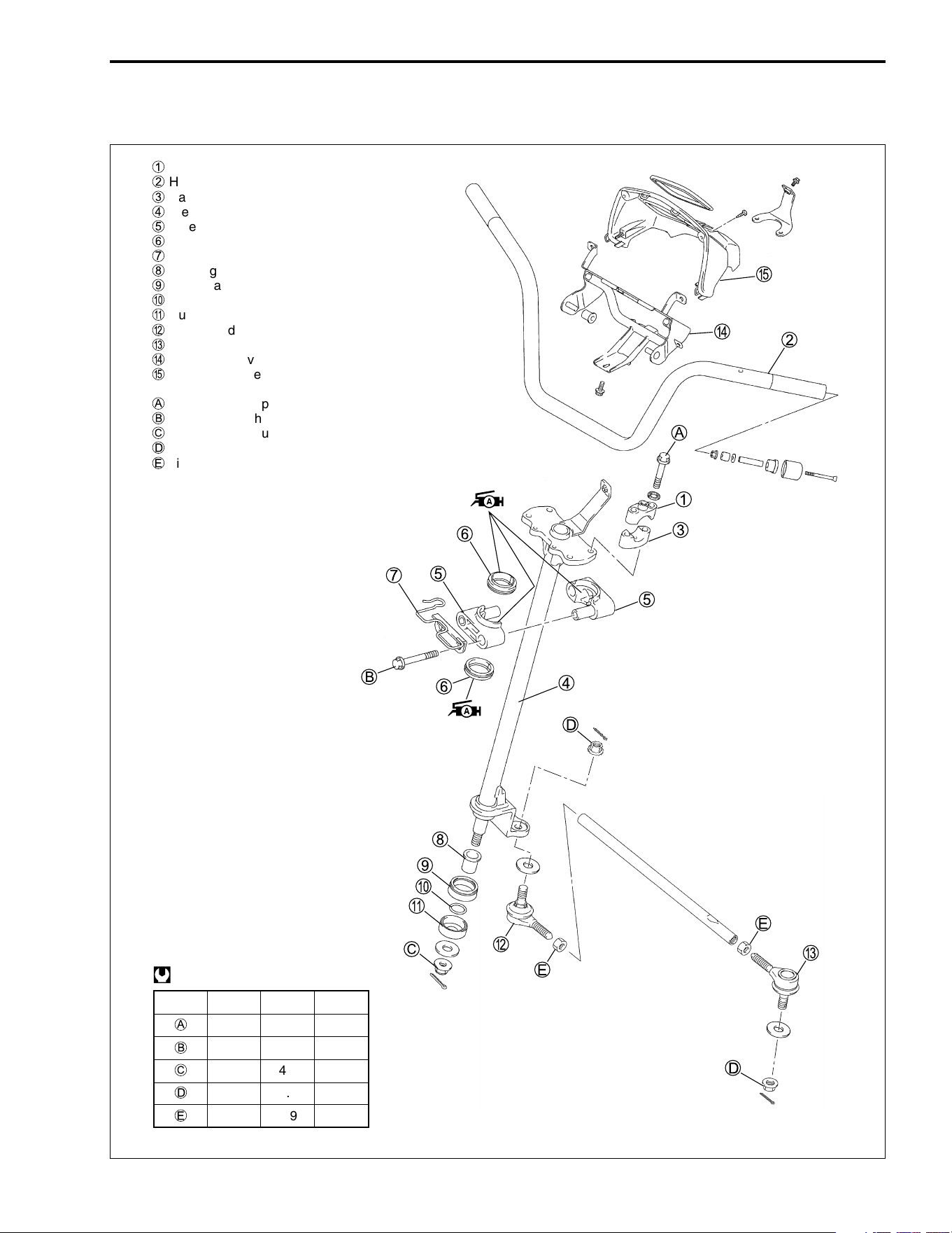
CHASSIS 7-41
STEERING
CONSTRUCTION
1
Handlebar upper clamp
2
Handlebars
3
Handlebar lower clamp
4
Steering shaft
5
Steering shaft holder
6
Dust seal
7
Cable guide
8
Bushing
9
Dust seal
0
O-ring
A
Dust seal
B
Tie rod end (inside)
C
Tie rod end (outside)
D
Handlebar cover bracket
E
Handlebar cover
A
Handlebar clamp bolt
B
Steering shaft holder bolt
C
Steering shaft nut
D
Tie rod end nut
E
Tie rod locknut
ITEM N·m kgf-m lb-ft
A
23 2.3 16.5
B
23 2.3 16.5
C
49 4.9 35.5
D
35 3.5 25.5
E
29 2.9 21.0
@
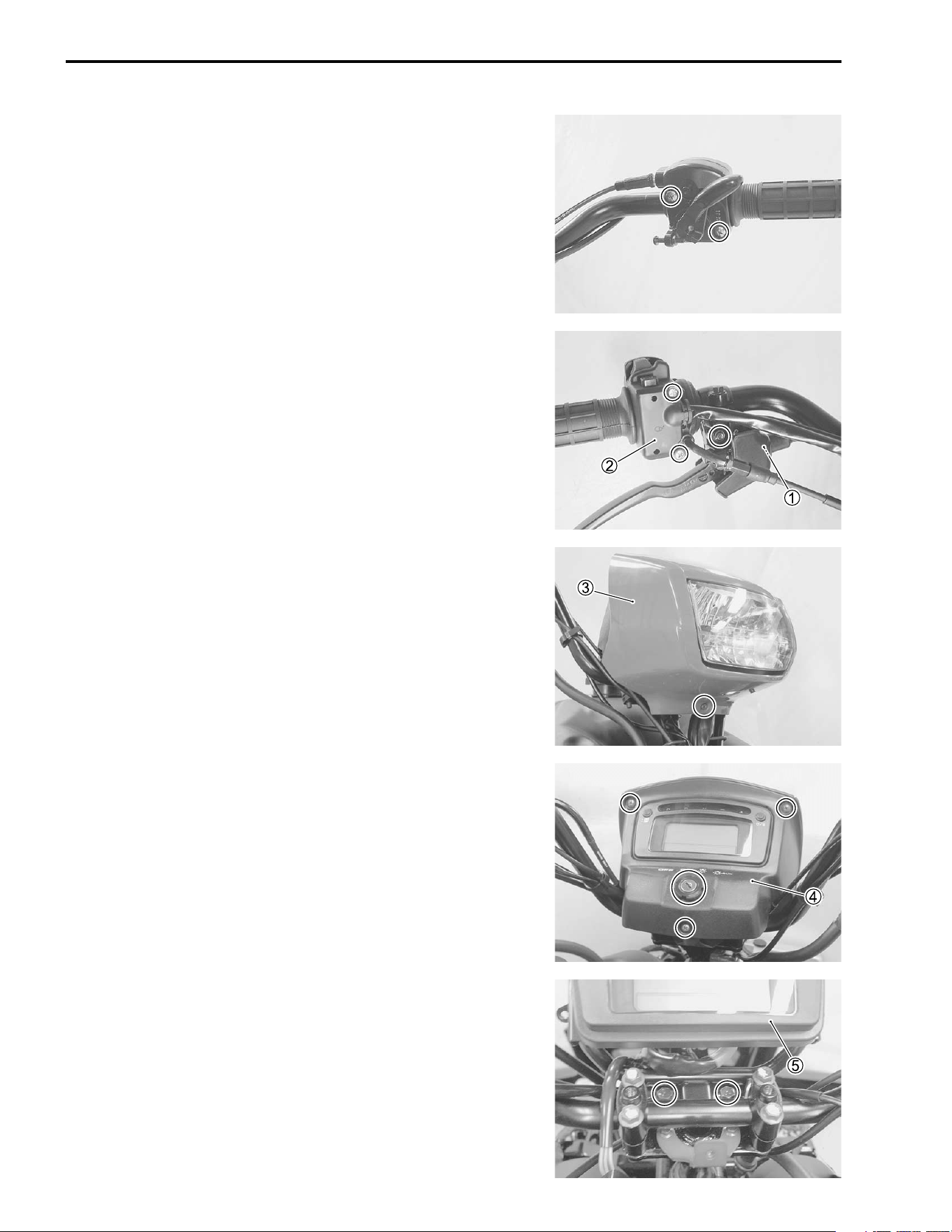
7-42 CHASSIS
REMOVAL AND DISASSEMBLY
• Remove the front fender. (!7-6)
• Remove the front wheel. (!7-11)
• Remove the master cylinder assembly. (!7-28)
• Remove the throttle lever case.
• Disconnect the rear brake cable
1 and remove the handlebar
switch
2.
• Remove the auxiliary light cover
3.
• Remove the speedometer cover
4.
• Remove the speedometer assembly
5.
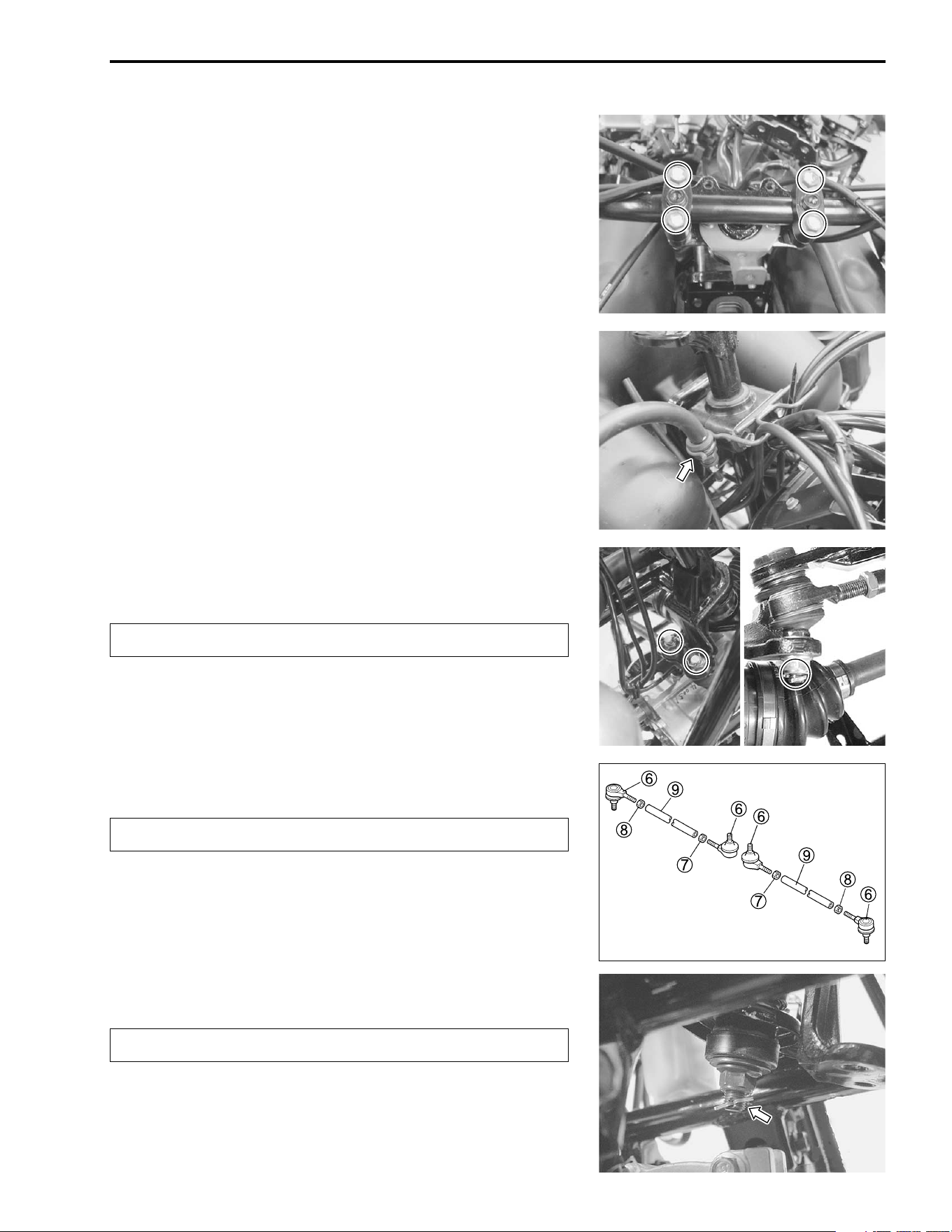
CHASSIS 7-43
• Remove the handlebar clamp bolts and handlebars assembly.
• Disconnect the brake hose from the clamp.
• Remove the cotter pins and tie rod end nuts.
• Remove the tie rods.
$
• Separate the tie rod ends
6, nuts
7 and
8, and tie rods
9.
$
• Remove the cotter pin and steering shaft nut.
$
Replace the removed cotter pins with new ones.
The locknuts
7 have left-hand threads.
Replace the removed cotter pins with new ones.
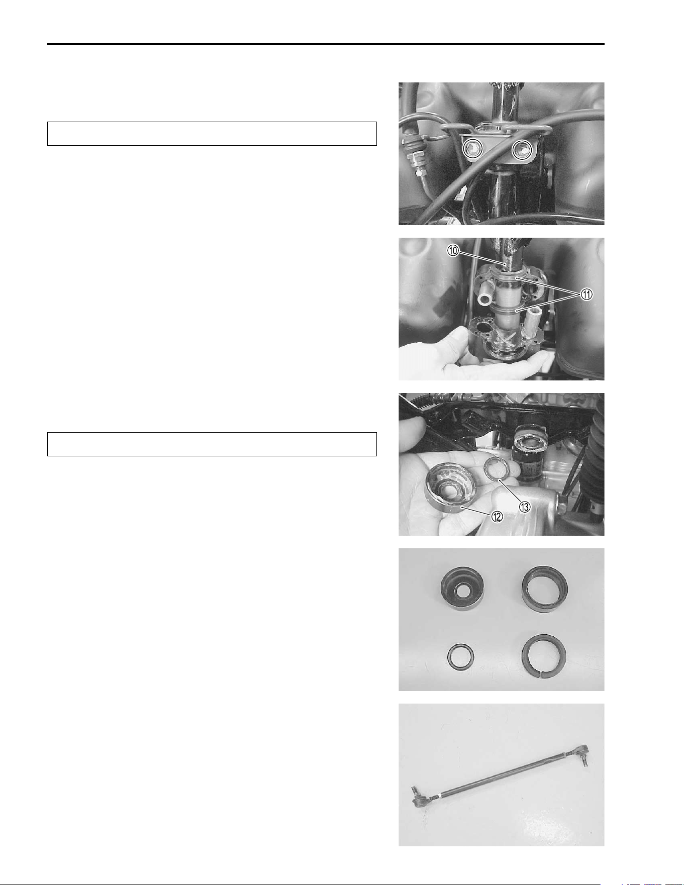
7-44 CHASSIS
• Remove the steering shaft holder bolts.
$
• Remove the steering shaft
0.
• Remove the dust seals
A from the steering shaft.
• Remove the dust seal
B and O-ring
C from the frame.
$
INSPECTION
Inspect the removed parts for the following abnormalities.
* Handlebar distortion
* Handlebar clamp wear
DUST SEALS AND O-RING
Inspect the dust seals and O-ring for wear or damage. If any
damages are found, replace the dust seals with new ones.
TIE ROD
Inspect the tie rod for distortion or damage. If any damages are
found, replace the tie rod with a new one.
TIE ROD END
Inspect the tie rod end and boots for smooth movement. If there
are any abnormalities, replace the tie rod end with a new one.
Replace the removed clips with new ones.
Replace the removed O-ring with a new one.
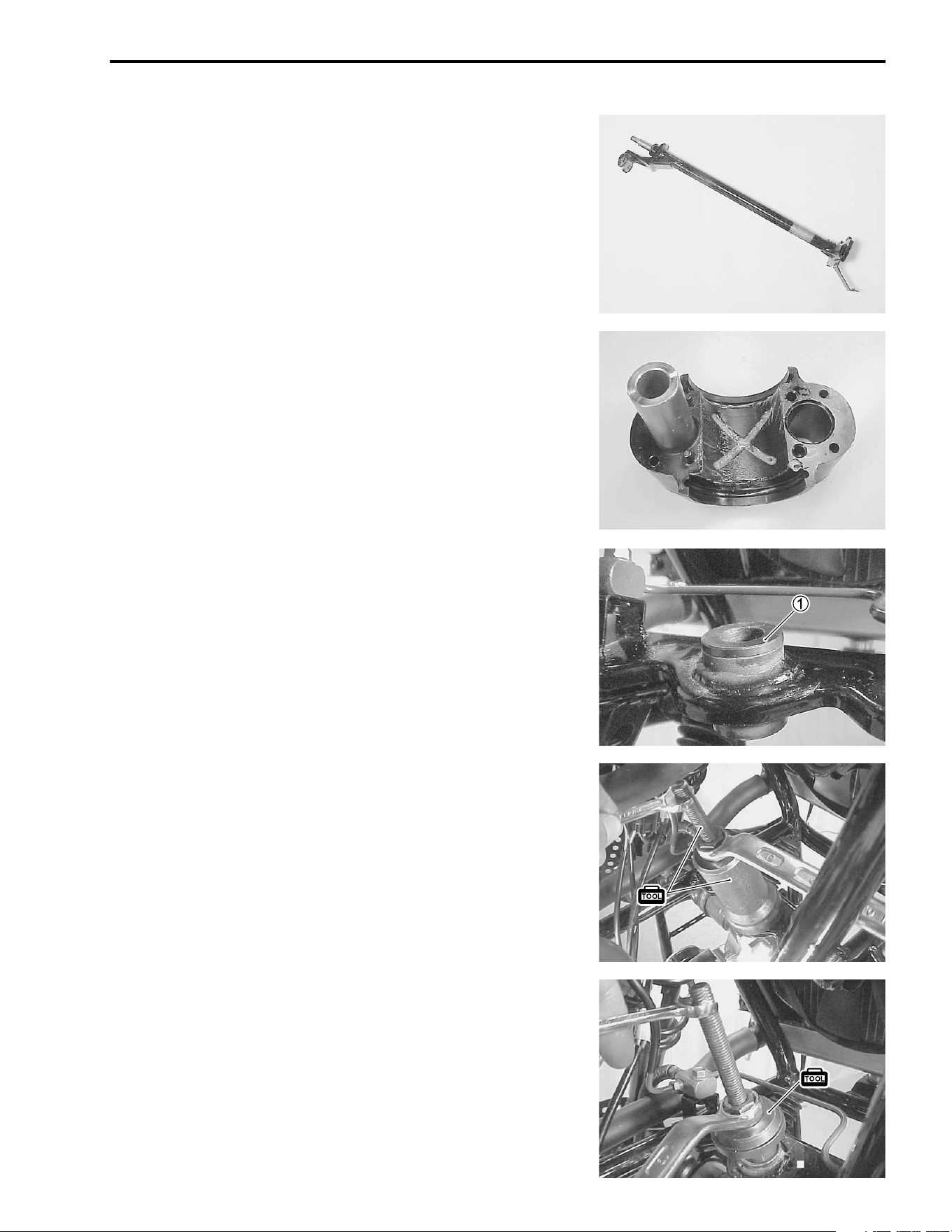
CHASSIS 7-45
STEERING SHAFT AND HOLDER
Inspect the steering shaft for distortion or bends. If any damages
are found, replace the steering shaft with a new one.
Inspect the two steering shaft holders for wear or damage. If any
damages are found, replace the steering shaft holders with new
ones.
STEERING SHAFT BUSHING
Inspect the steering shaft bushing
1 for wear and damage. If
any damages are found, replace it with a new one.
• Remove the steering shaft bushing with the special tools.
* 09917-23711: Ring nut socket
09924-84510: Bearing installer set
• Install the steering shaft bushing with the special tool.
* 09924-84510: Bearing installer set
7-46 CHASSIS
REASSEMBLY AND REMOUNTING
Reassemble and remount the steering stem in the reverse order
of removal and disassembly. Pay attention to the following
points:
STEERING SHAFT
• Apply SUZUKI SUPER GREASE “A” to the O-ring and dust
seals before remounting the steering shaft.
+ 99000-25030: SUZUKI SUPER GREASE “A” (USA)
99000-25010: SUZUKI SUPER GREASE “A” (Others)
• Install the dust seal
1 to the steering shaft.
• Install the clip
2 to the dust seal.
• Install the new O-ring
3 and dust seal to the steering shaft.
• Tighten the steering shaft nut to the specified torque.
# Steering shaft nut: 49 N·m (4.9 kgf-m, 35.5 lb-ft)
NOTE:
After installing the steering shaft nut, install a new cotter pin into
the steering shaft.
• Apply SUZUKI SUPER GREASE “A” to the steering shaft
holders and dust seals before remounting the steering shaft
holders.
+ 99000-25030: SUZUKI SUPER GREASE “A” (USA)
99000-25010: SUZUKI SUPER GREASE “A” (Others)
$
To prevent the entry of dirt, the dust seal ends
4 must
face forward when installed to the steering shaft.
CHASSIS 7-47
• Tighten the steering shaft holder bolts to the specified torque.
# Steering shaft holder bolt: 23 N·m (2.3 kgf-m, 16.5 lb-ft)
NOTE:
Make sure that the wiring harness, cables and brake hose rout-
ing are proper. (!9-12 to -20)
TIE ROD
• Install the washer between the tie rod end and steering
knuckle.
• Tighten the tie rod end nuts to the specified torque.
# Tie rod end nut: 60 N·m (6.0 kgf-m, 43.5 lb-ft)
NOTE:
After installing the tie rod end nuts, install the new cotter pins
into the tie rod end.
• When installing the tie rod, make sure the narrow end
1 of
the tie rod comes out.
$
HANDLEBARS
When installing the lower handlebar holder
1 to the steering
shaft, the higher mating portion must face to forward.
• Set the handlebars to match its punched mark
2 to the mat-
ing face of the handlebar clamps.
• First tighten the bolts
3 to the specified torque and then
tighten the bolts
4.
# Handlebar clamp bolt: 23 N·m (2.3 kgf-m, 16.5 lb-ft)
• Install the handle switch with the lug
5 on the switch half
inserted into the hole
6 on the handlebars.
NOTE:
After installing the handlebars, make sure that the cable, wiring
harness and brake hose routing are proper.
(!9-12 to -20)
The locknuts
2 have left-hand threads.
Forward
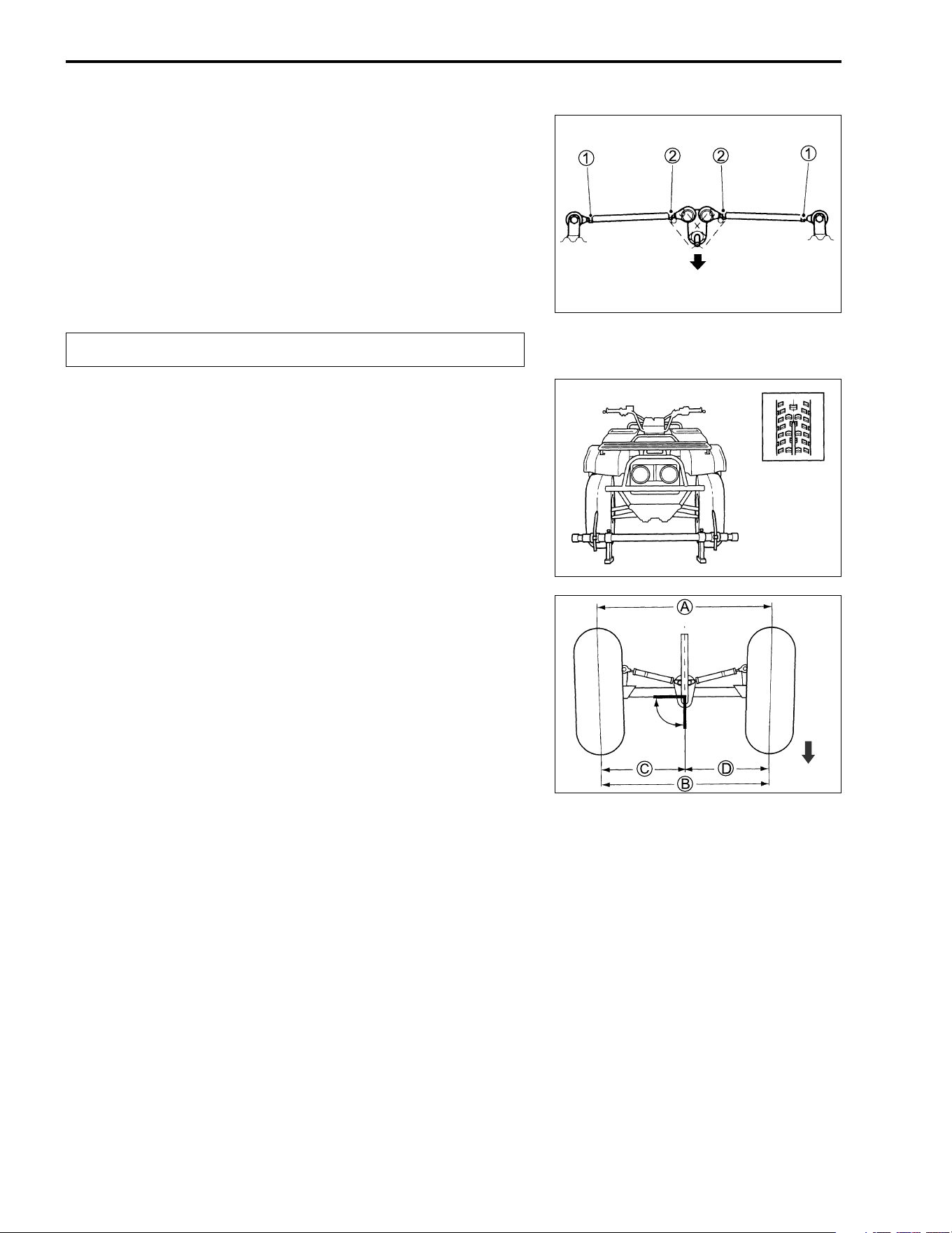
7-48 CHASSIS
TOE-IN ADJUSTMENT
Adjust the toe-in as follows:
• Place the vehicle on level ground and set the handlebars
straight.
Make sure all the tires are inflated to the standard pressure.
(!2-18)
• Place 75 kg (165 lbs) of weight on the seat.
• Loosen the locknuts (
1,
2) on each tie rod.
$
• Measure the distances (
A and
B) between the front wheels.
Subtract the measurements of
A from the measurements of
B to find the toe-in. If the toe-in is not within specification,
adjust the tie rod to the right or left until the toe-in is within the
specified range.
A –
B = Toe-in
% Toe-in
Standard: 7 ± 4 mm (0.28 ± 0.16 in)
• Temporarily tighten the four locknuts.
• Check that the distances (
C and
D) are equal, as shown. If
the distances are not equal, adjust the tie rod to the right or
left until the toe-in is within specification. Check the toe-in
again by measuring distances
A and
B.
• If the toe-in is not within specification, repeat the adjustment
as above until the proper toe-in is obtained and distances
C
and
D become equal.
• After adjustment has been made, tighten the four locknuts
1
to the specified torque.
# Tie rod locknut: 29 N·m (2.9 kgf-m, 21.0 lb-ft)
The locknuts
2 have left-hand threads.
Forward
Right angle
(90 deg.)
Forward
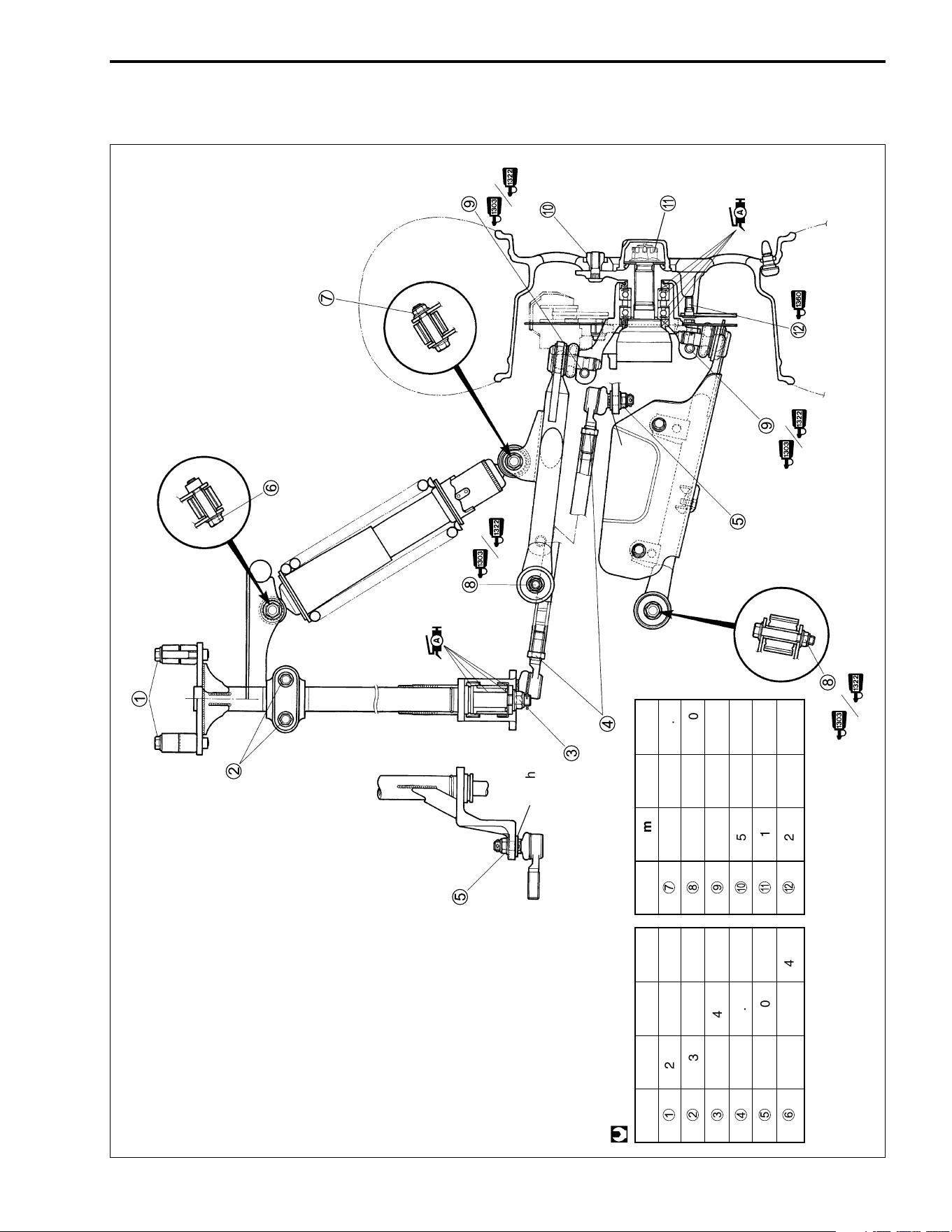
CHASSIS 7-49
FRONT WHEEL, FRONT BRAKE, FRONT SUSPENSION AND
STEERING REASSEMBLING INFORMATION
ITEM N·m kgf-m lb-ft
1
23 2.3 16.5
2
23 2.3 16.5
3
49 4.9 35.5
4
29 2.9 21.0
5
60 6.0 43.5
6
55 5.5 40.0
@
ITEM N·m kgf-m lb-ft
7
60 6.0 43.5
8
65 6.5 47.0
9
50 5.0 36.0
0
50 5.0 36.0
A
110 11.0 79.5
B
23 2.3 16.5
Washer
Washer
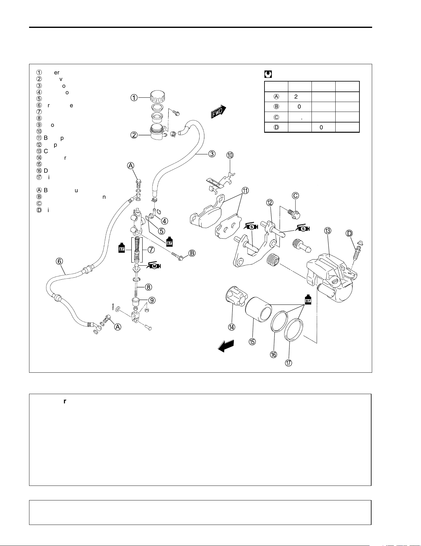
7-50 CHASSIS
REAR BRAKE
CONSTRUCTION
&
$
FWD
ITEM N·m kgf
-
m lb-ft
A
23.0 2.3 16.5
B
10.0 1.0 7.0
C
32.0 3.2 23.0
D
7.5 0.8 5.5
@
1
Reservoir tank cap
2
Reservoir tank
3
Reservoir hose
4
Connector
5
O-ring
6
Brake hose
7
Piston/cup set
8
Push rod
9
Boot
0
Spring
A
Brake pad
B
Caliper holder
C
Caliper
D
Insulator
E
Piston
F
Dust seal
G
Oil seal
A
Brake hose union bolt
B
Master cylinder mounting bolt
C
Caliper mounting bolt
D
Air bleeder valve
* This brake system is filled with an ethylene glycol-based DOT 4 brake fluid. Do not use or mix
different types of fluid, such as silicone-based or petroleum-based brake fluids.
* Do not use any brake fluid taken from old, used or unsealed containers. Never reuse brake
fluid left over from the last servicing or which has been stored for a long periods of time.
* When storing brake fluid, seal the container completely and keep it away from children.
* When replenishing brake fluid, take care not to get dust into the fluid.
* When washing brake components, use new brake fluid. Never use cleaning solvent.
* A contaminated brake disc or brake pad reduces braking performance. Discard contaminated
pads and clean the brake disc with high quality brake cleaner or a neutral detergent.
Handle brake fluid with care: the fluid reacts chemically with paint, plastics, rubber materials
etc. and will damage them severly.
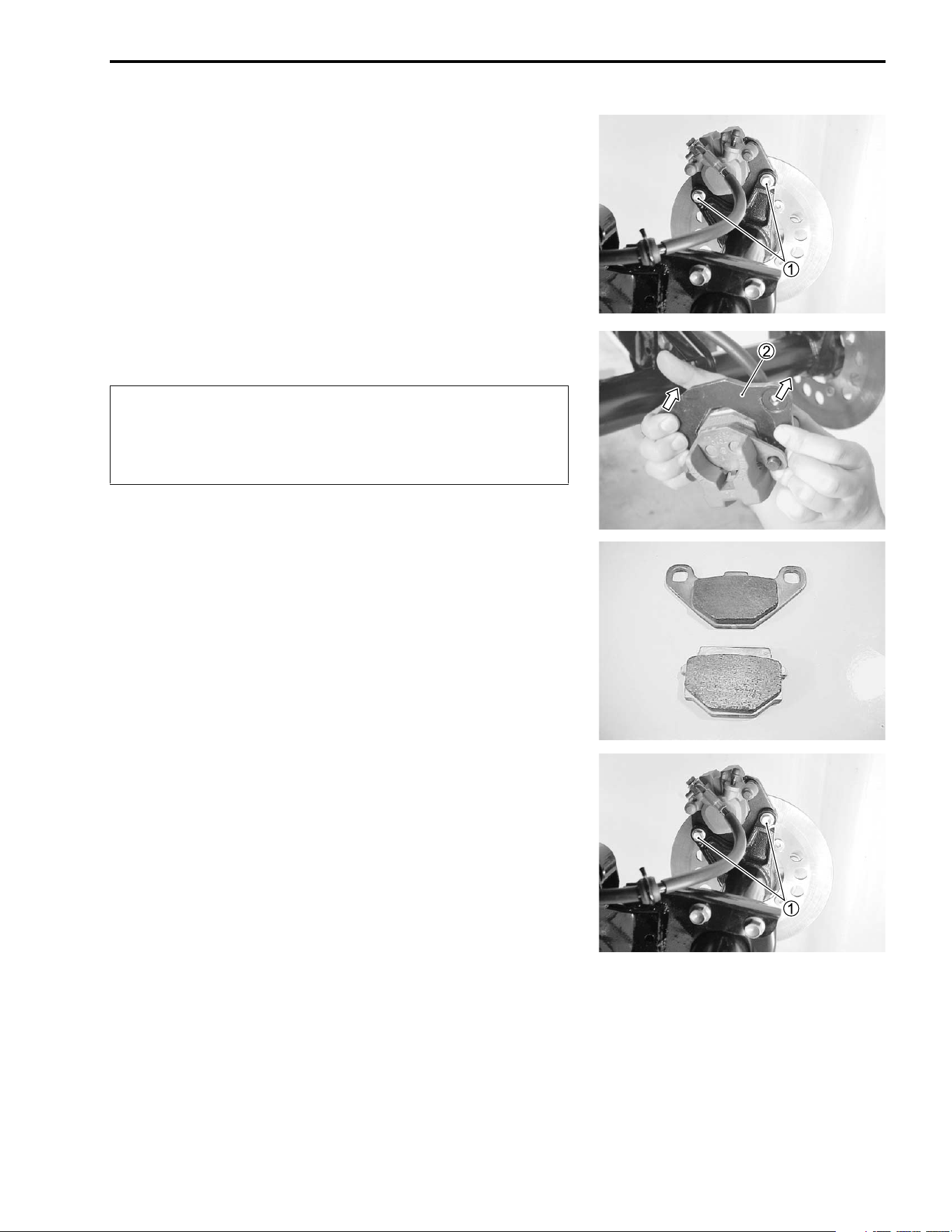
CHASSIS 7-51
BRAKE PAD REPLACEMENT
• Remove the right rear wheel. (!7-11)
• Remove the brake caliper mounting bolts
1.
• With pushing the caliper holder
2, remove the brake pads.
$
• Install the new brake pads in the reverse order of removal.
• Tighten the brake caliper mounting bolts
1 to the specified
torque.
# Brake caliper mounting bolts:
32 N·m (3.2 kgf-m, 23.0 lb-ft)
NOTE:
After replacing the brake pads, pump the brake lever a few times
to check for proper brake operation and then check the brake
fluid level.
* Do not operate the brake lever during or after brake
pad removal.
* Replace the brake pads as a set, otherwise braking
performance will be adversely affected.
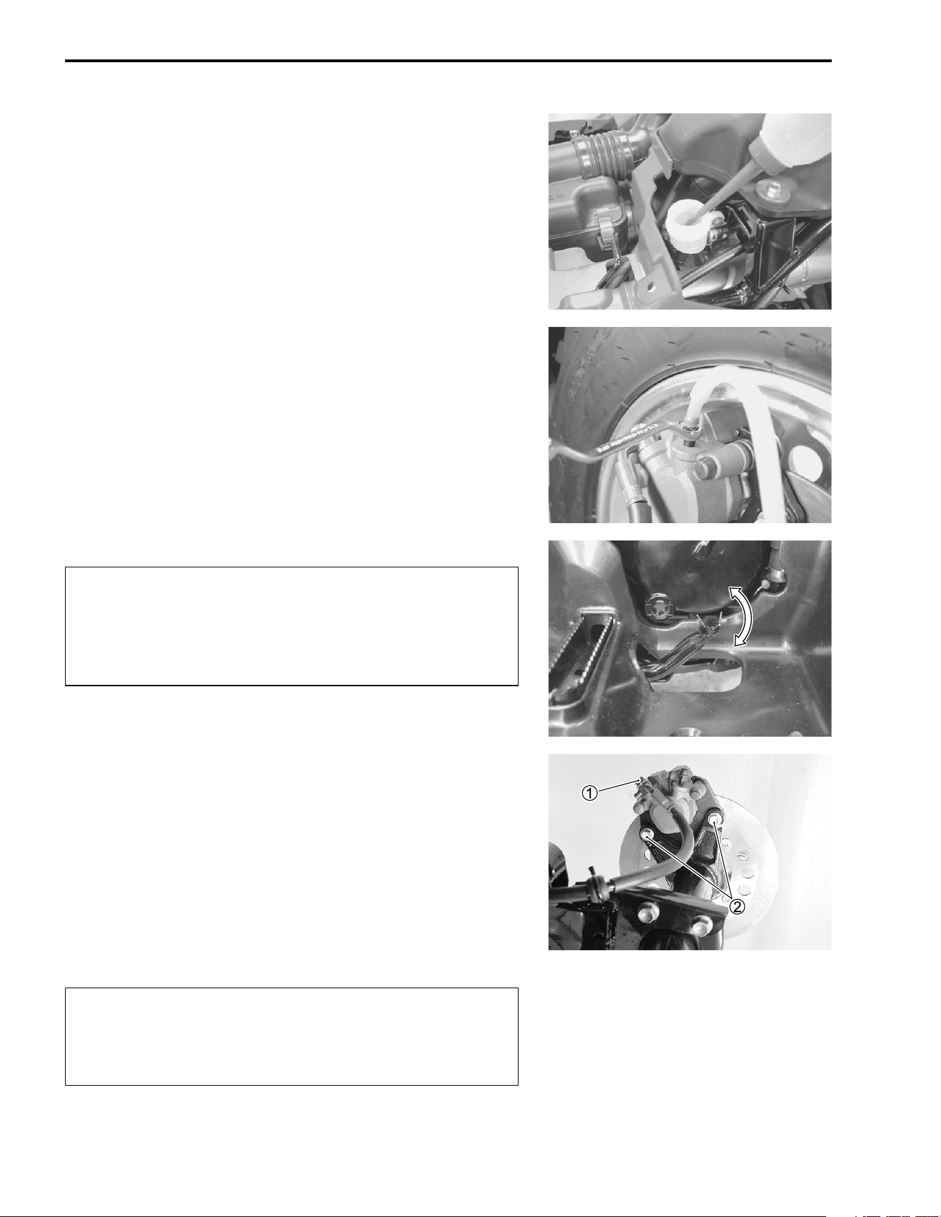
7-52 CHASSIS
BRAKE FLUID REPLACEMENT
• Place the vehicle on a level surface.
• Remove the seat and fuel tank covers. (! 7-4 and 7-5)
• Remove the master cylinder reservoir cap and diaphragm.
• Suck up the old brake fluid as much as possible.
• Fill the reservoir with new brake fluid.
' Specification and classification: DOT 4
• Connect a clear hose to the air bleeder valve and insert the
other end of the hose into a receptacle.
• Loosen the air bleeder valve and pump the brake lever until
the old brake fluid is completely out of the brake system.
• Close the air bleeder valve and disconnect the clear hose. Fill
the reservoir with new brake fluid to the upper end of the
inspection window.
$
BRAKE CALIPER REMOVAL AND
DISASSEMBLY
• Remove the right rear wheel. (!7-11)
• Disconnect the brake hose from the brake caliper by remov-
ing the brake hose union bolt
1 and allow the brake fluid to
drain into a suitable receptacle.
• Remove the brake caliper by removing the brake caliper
mounting bolts
2.
• Remove the brake pads. (!7-51)
$
* Never reuse the brake fluid left over from previous
servicing and which has been stored for long peri-
ods of time.
* Bleed air from the brake system.
(!2-17)
Immediately wipe off any brake fluid contacting any
part of the vehicle. The brake fluid reacts chemically
with paint, plastics, rubber materials, etc., and will
damage them severely.
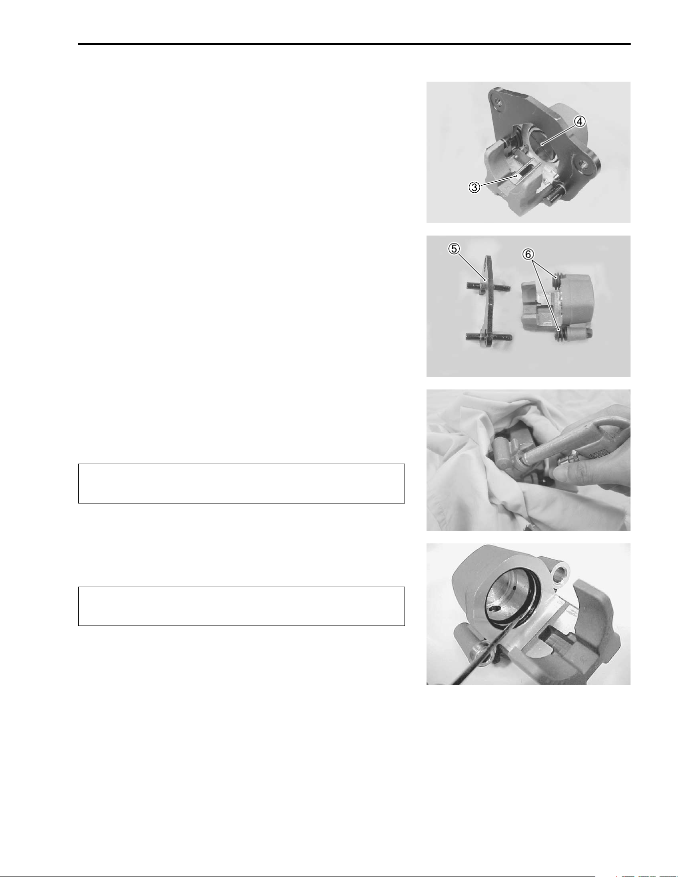
CHASSIS 7-53
• Remove the spring
3 and insulator
4.
• Remove the brake caliper holder
5 and rubber parts
6.
• Place a rag over the brake caliper pistons to prevent them
from popping out and then force out the pistons using com-
pressed air.
$
• Remove the dust seal and piston seal.
$
Do not use high pressure air to prevent brake caliper
piston damage.
Do not reuse the dust seal and piston seal to prevent
fluid leakage.
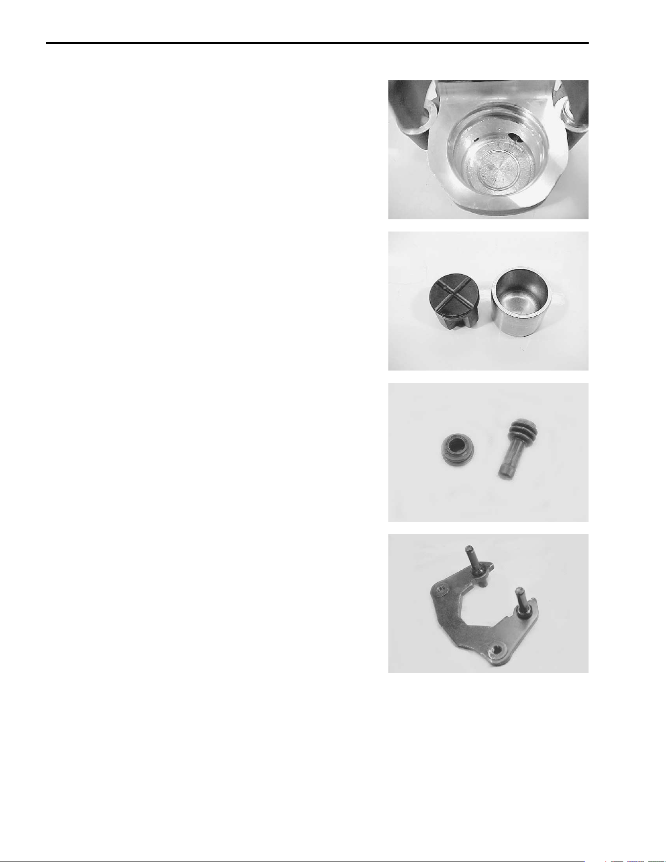
7-54 CHASSIS
BRAKE CALIPER INSPECTION
BRAKE CALIPER
Inspect the brake caliper cylinder wall for nicks, scratches or
other damage. If any damages are found, replace the brake cal-
iper with a new one.
BRAKE CALIPER PISTON/INSULATOR
Inspect the brake caliper piston and insulator for any scratches
or other damage. If any damages are found, replace the piston/
insulator with a new one.
RUBBER PARTS
Replace the removed rubber parts with new ones.
CALIPER HOLDER
Inspect the caliper holder for damage. If any damages are
found, replace the caliper holder with new ones.
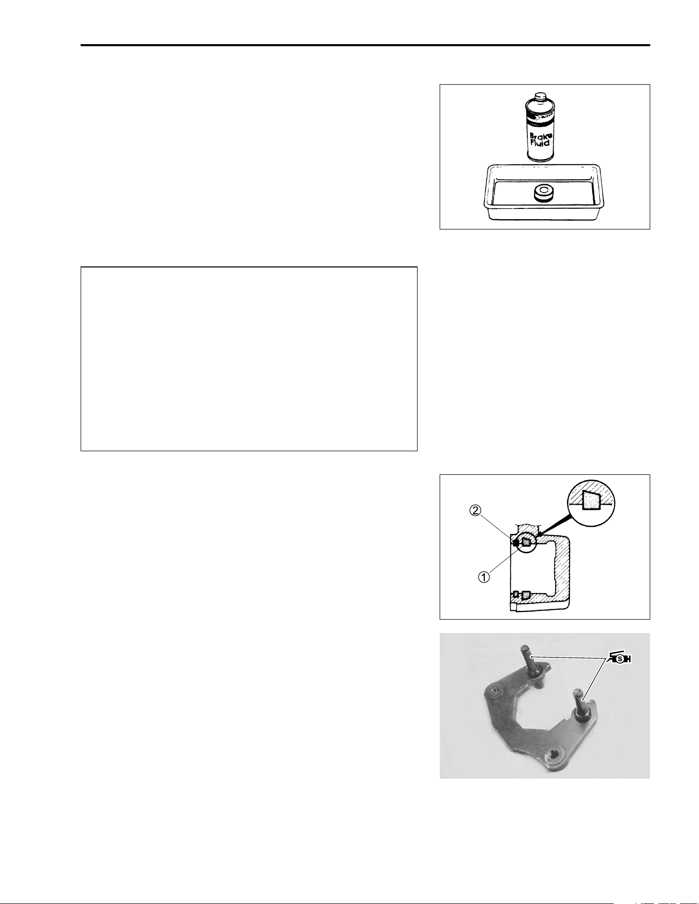
CHASSIS 7-55
BRAKE CALIPER REASSEMBLY AND
REMOUNTING
Reassemble and remount the brake caliper in the reverse order
of removal and disassembly. Pay attention to the following
points:
• Wash the caliper bores and pistons with the specified brake
fluid. Thoroughly wash the dust seal groove and piston seal
groove.
' Specification and classification: DOT 4
$
PISTON SEALS
• Install the piston seal
1 and dust seal
2 as shown.
BRAKE CALIPER HOLDER
• Apply SUZUKI SILICON GREASE to the pin.
( 99000-25100: SUZUKI SILICON GREASE
* Wash the brake caliper components with new brake
fluid before reassembly.
* Do not wipe the brake fluid off with a rag after wash-
ing the components.
* When washing the components, use the specified
brake fluid. Never use different types of fluid or
cleaning solvents such as gasoline, kerosine, etc.
* Replace the removed piston seals and dust seals
with new ones.
* Apply brake fluid to all of the seals, brake caliper
bores and pistons before reassembly.
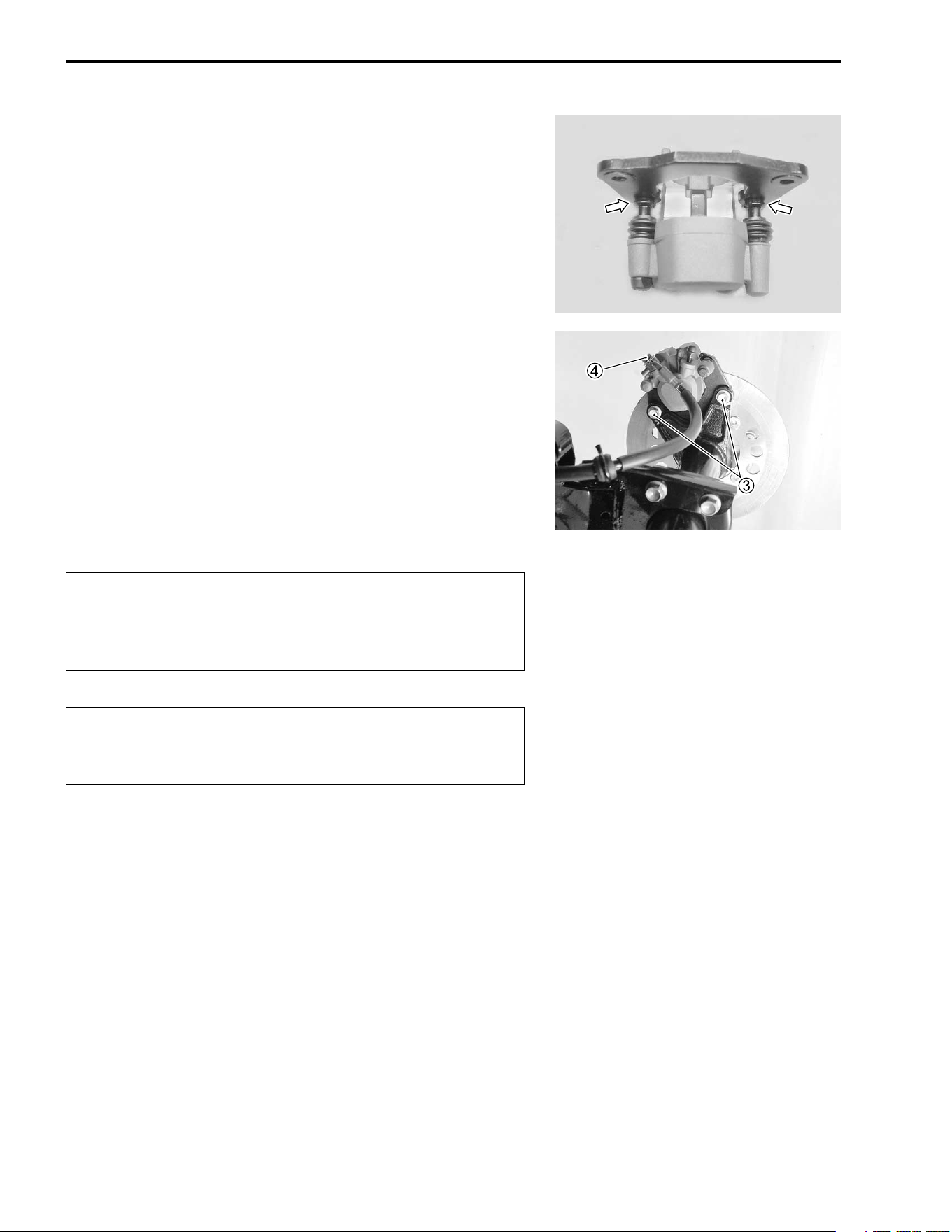
7-56 CHASSIS
• Assemble the caliper holder and the caliper.
NOTE:
Make sure that the boots must be set into the holder pin’s
grooves securely.
• Install the piston, insulator and spring.
• Install the pads to the caliper. (!7-51)
• Tighten the brake caliper mounting bolts
3, and brake hose
union bolt
4 to the specified torque.
(Rear brake hose routing: !9-21)
# Brake caliper mounting bolt:
32 N·m (3.2 kgf-m, 23.0 lb-ft)
Brake hose union bolt: 23 N·m (2.3 kgf-m, 16.5 lb-ft)
NOTE:
Before remounting the brake caliper, push the brake caliper pis-
ton all the way into the caliper.
$
&
* The seal washers should be replaced by the new
ones to prevent fluid leakage.
* Bleed air from the brake system after reassembling
the master cylinder. (!2-16)
Brake fluid, if it leaks, will interfere with safe running
and discolor painted surfaces. Check the brake hose
and hose joints for cracks and oil leakage.
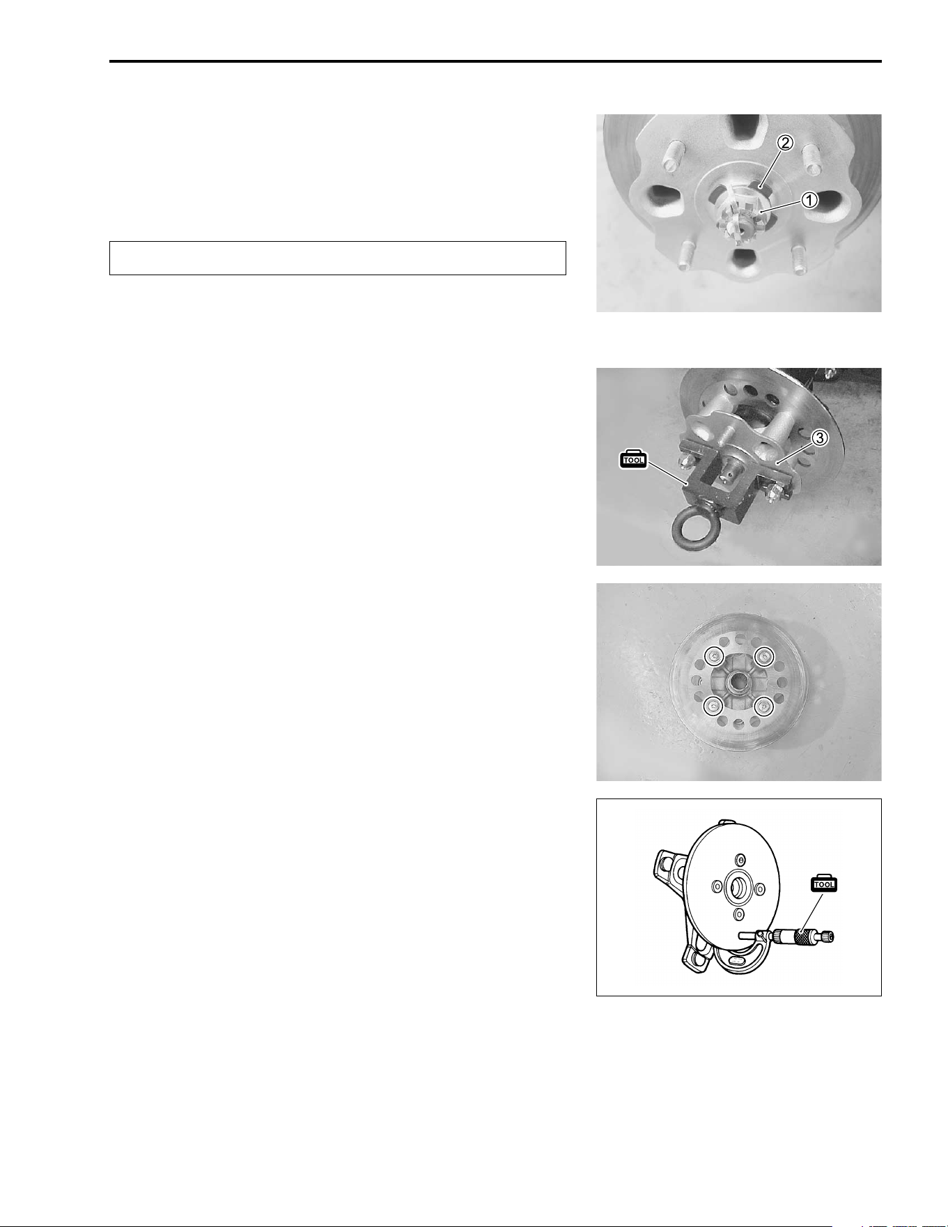
CHASSIS 7-57
BRAKE DISC REMOVAL AND
DISASSEMBLY
• Remove the right rear wheel. (!7-11)
• Remove the cotter pin.
$
• Loosen the axle nut
1 by applying the rear brake.
• Remove the rear brake caliper. (!7-51)
• Remove the axle nut
1 and spring washer
2.
• Remove the rear wheel hub
3.
NOTE:
Use the special tool if necessary.
* 09924-21940: Wheel hub remover
09930-30104: Sliding hammer
• Remove the brake disc.
BRAKE DISC INSPECTION
• Remove the right rear wheel. (!7-11)
Inspect the brake disc for cracks or damage and measure the
thickness using the micrometer. If any damages are found or if
the thickness is less than the service limit, replace the brake disc
with a new one.
* 09900-20205: Micrometer (0 – 25 mm)
% Brake disc thickness
Service Limit: 3.5 mm (0.14 in)
Replace the removed cotter pin with a new one.
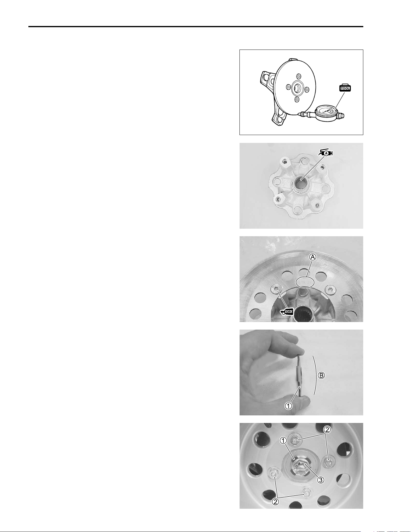
7-58 CHASSIS
Measure the runout using the dial gauge. If the runout exceeds
the service limit, replace the brake disc with a new one.
* 09900-20607: Dial gauge (1/100 mm)
09900-20701: Magnetic stand
% Brake disc runout
Service Limit: 0.3 mm (0.012 in)
• If either measurement exceeds the service limit, replace the
brake disc with a new one.
BRAKE DISC REASSEMBLY AND
REMOUNTING
Reassemble and remount the brake disc in the reverse order of
removal and disassembly. Pay attention to the following points:
• Apply SUZUKI SUPER GREASE “A” to the wheel hub spline.
+ 99000-25030: SUZUKI SUPER GREASE “A” (USA)
99000-25010: SUZUKI SUPER GREASE “A” (Others)
• Apply THREAD LOCK SUPER “1360” to the brake disc bolts
and tighten them to the specified torque.
) 99000-32130: THREAD LOCK SUPER “1360”
# Brake disc bolt: 23 N·m (2.3 kgf-m, 16.5 lb-ft)
NOTE:
Stamped mark
A on the brake disc must face outside.
• Install the spring washer
1 as its convex side
B faces to the
rear hub nut.
• Tighten the rear wheel set nuts
2, and hub nut
3 to the
specified torque.
# Rear wheel set nut: 50 N·m (5.0 kgf-m, 36.0 lb-ft)
Rear hub nut: 110 N·m (11.0 kgf-m, 79.5 lb-ft)
NOTE:
* First, remount the rear wheels and lower the jack, and then
tighten the rear hub nut to specified torque.
* After installing the rear hub nut, insert a new cotter pin into the
rear axle shaft.
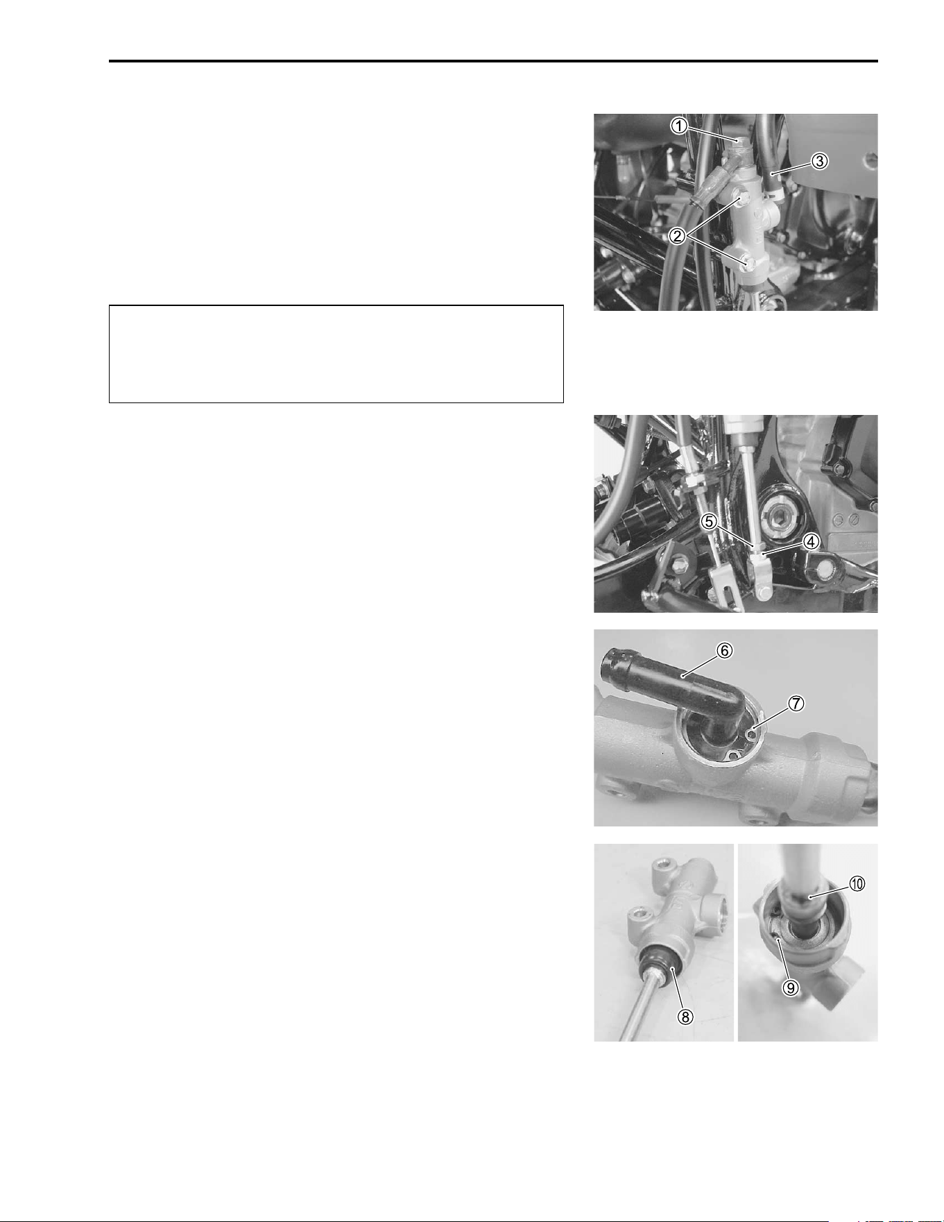
CHASSIS 7-59
MASTER CYLINDER REMOVAL AND
DISASSEMBLY
• Place a rag underneath the brake hose union bolt on the mas-
ter cylinder to catch any spilt brake fluid. Remove the brake
hose union bolt
1 and disconnect the brake hose.
• Remove the master cylinder mounting bolts
2.
• Disconnect the reservoir hose
3.
$
• Loosen the locknut
4.
• Remove the master cylinder assembly by turning the master
cylinder rod
5.
• Remove the connector
6 and O-ring by removing the snap
ring
7.
• Remove the boot
8 and snap ring
9.
• Remove the push rod
0.
Immediately wipe off any brake fluid contacting any
part of the vehicle. The brake fluid reacts chemically
with paint, plastics, rubber materials, etc., and will
damage them severely.
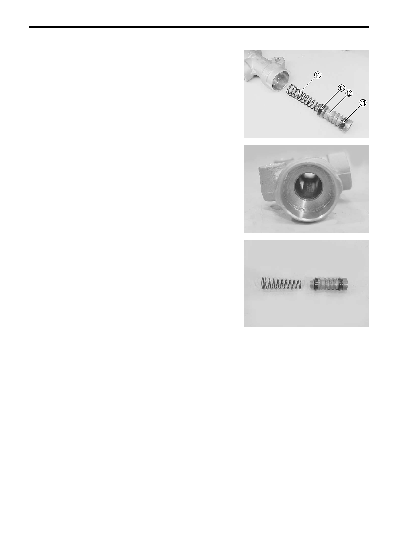
7-60 CHASSIS
• Remove the piston/secondary cup, primary cup and spring.
A Secondary cup
B Piston
C Primary cup
D Spring
MASTER CYLINDER INSPECTION
MASTER CYLINDER
Inspect the master cylinder bore for any scratches or damage. If
any damages are found, replace the master cylinder with a new
one.
PISTON AND RUBBER PARTS
Inspect the piston surface, primary cup, secondary cup and boot
for any scratches, wear or damage. If any damages are found,
replace them with new ones.
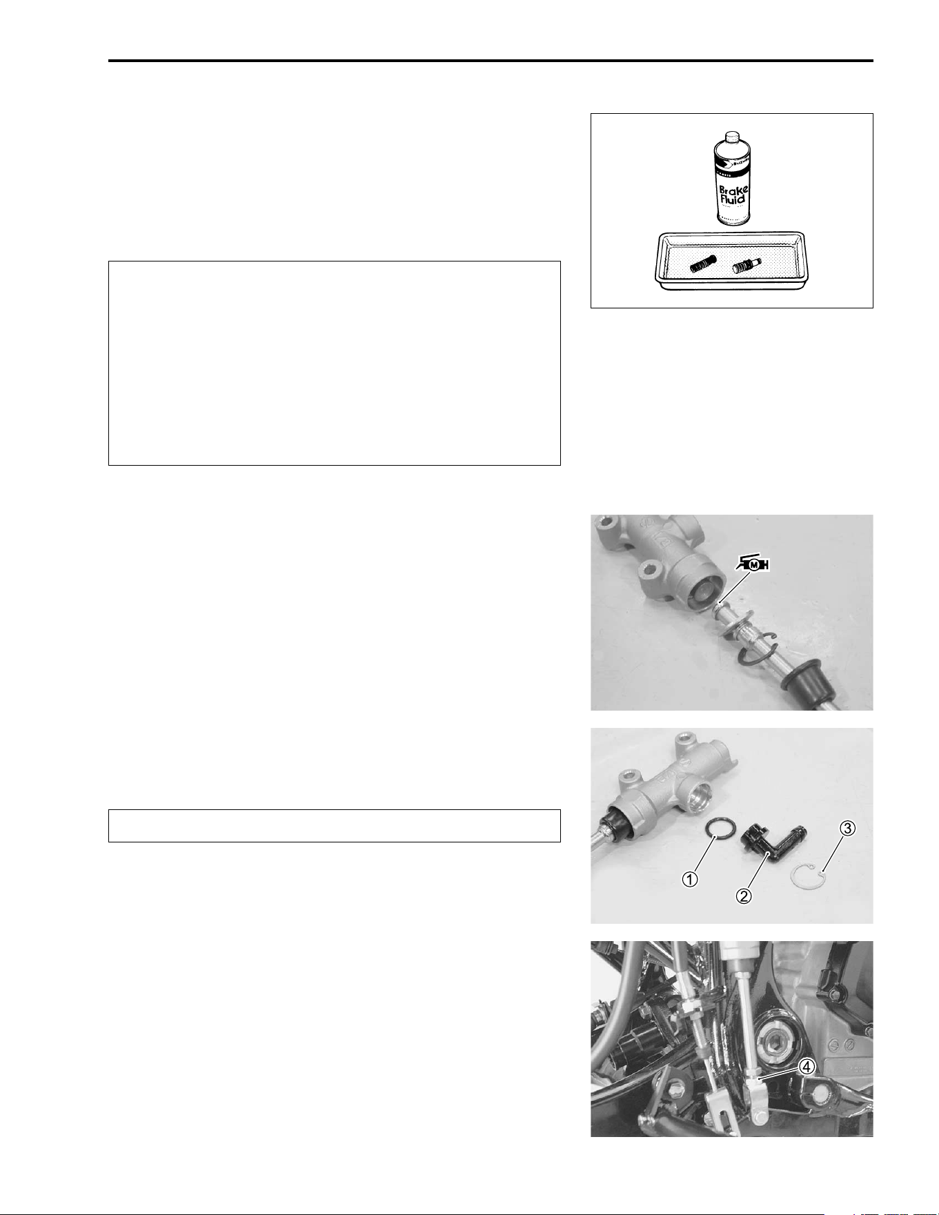
CHASSIS 7-61
MASTER CYLINDER REASSEMBLY AND
REMOUNTING
Reassemble and remount the master cylinder in the reverse
order of removal and disassembly. Pay attention to the following
points:
$
' Specification and classification: DOT 4
• Apply the SUZUKI MOLY PASTE to the push rod.
. 99000-25140: SUZUKI MOLY PASTE
• Install the push rod.
• Install the O-ring
1, connector
2 and snap ring
3 to the
master cylinder.
$
• Install the master cylinder.
• Tighten the locknut
4.
# Rear master cylinder rod locknut:
18 N·m (1.8 kgf-m, 13.0 lb-ft)
* Wash the master cylinder components with new
brake fluid before reassembly.
* Do not wipe the brake fluid off with a rag after wash-
ing the components.
* When washing the components, use the specified
brake fluid. Never use different types of fluid or
cleaning solvents such as gasoline, kerosine, etc.
* Apply brake fluid to the master cylinder bore and all
the component to be inserted into the bore.
Replace the O-ring with a new one.
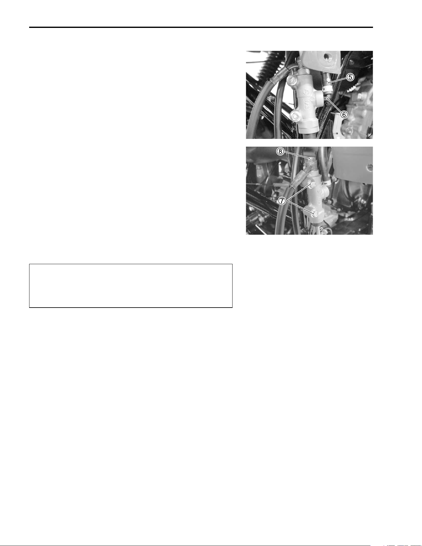
7-62 CHASSIS
• Connect the reservoir hose
5 to the connector
6.
• Tighten the master cylinder mounting bolts
7 to the specified
torque.
• Connect the brake hose to the master cylinder.
(Rear brake hose routing: !9-21)
• Tighten the brake hose union bolt
8 to the specified torque.
# Rear master cylinder mounting bolt:
10 N·m (1.0 kgf-m, 7.3 lb-ft)
Brake hose union bolt: 23 N·m (2.3 kgf-m, 16.5 lb-ft)
• Adjust the brake pedal height and rear brake lever. (!2-15)
$
* The seal washers should be replaced by the new
ones to prevent fluid leakage.
* Bleed air from the brake system after reassembling
the master cylinder. (!2-17)
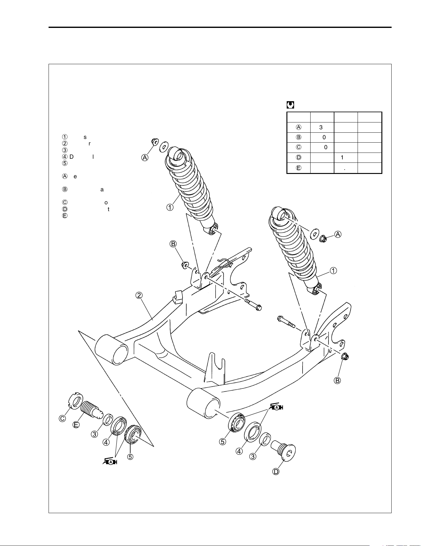
CHASSIS 7-63
REAR SUSPENSION
CONSTRUCTION
ITEM N·m kgf
-
m lb-ft
A
35 3.5 25.5
B
60 6.0 43.5
C
100 10.0 72.5
D
100 10.0 72.5
E
9.5 0.95 7.0
@
1
Rear shock absorber
2
Swingarm
3
Spacer
4
Dust seal
5
Bearing
A
Rear shock absorber mounting
upper nut
B
Rear shock absorber mounting
lower nut
C
Swingarm pivot locknut
D
Swingarm pivot bolt (LH)
E
Swingarm pivot bolt (RH)
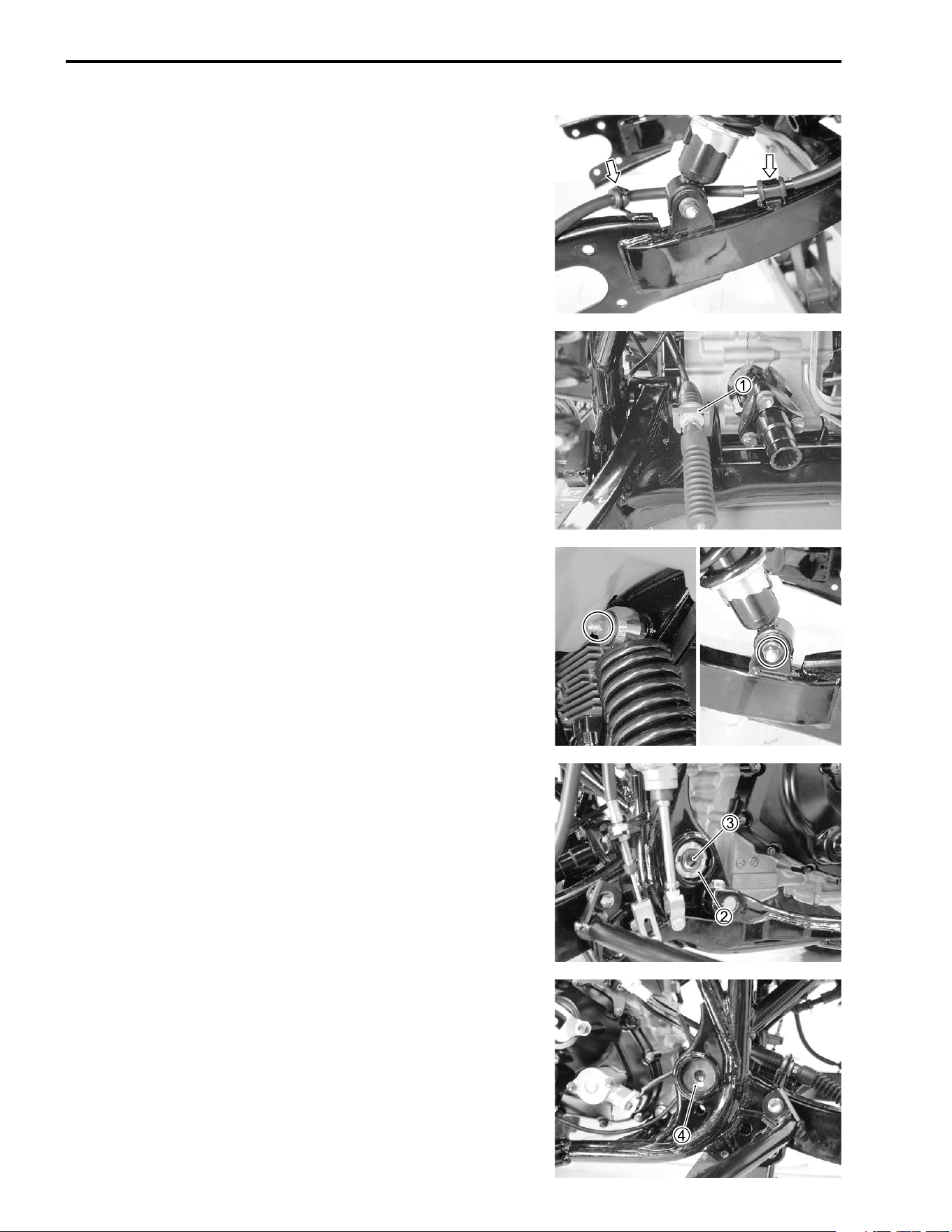
7-64 CHASSIS
REMOVAL
• Remove the mud guards (left and right). (!7-8)
• Remove the rear wheels. (!7-11)
• Remove the rear caliper. (!7-51)
• Remove the rear drive gear case and rear axle housings.
(!4-22)
• Disconnect the rear brake hose from the clamp and guide.
• Disconnect the parking cable from the swingarm by removing
the clip
1.
• Remove the rear shock absorbers (left and right).
• Loosen the swingarm pivot bolt locknut
2 with the special
tool.
* 09940-14970: Swingarm pivot adjust wrench
• Remove the swingarm pivot bolt
3 (RH) with the special tool.
* 09900-18710: Hexagon socket (12 mm)
• Remove the swingarm pivot bolt
4 (LH).
• Remove the rear swingarm.
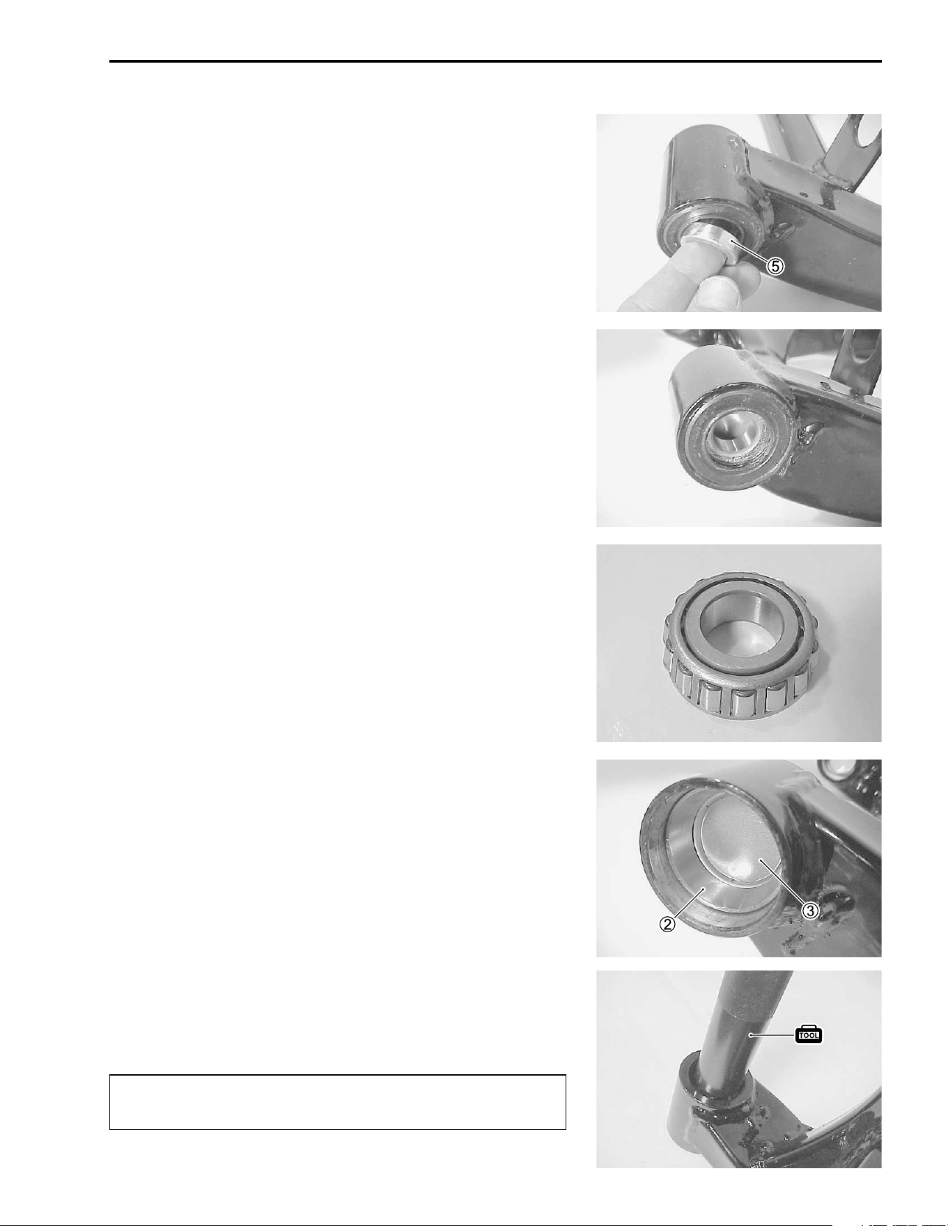
CHASSIS 7-65
• Remove the pivot spacers
5.
INSPECTION AND DISASSEMBLY
DUST SEAL AND SPACERS
Inspect the spacer and dust seal for wear or damage. If any
damages are found, replace them with new ones.
SWINGARM BEARING
• Remove the dust seals with the special tool.
• Remove the swingarm bearings.
• Inspect the swingarm bearing
1, outer race
2 and bearing
plate
3, if any damages are found, replace the swingarm
bearing with a new one.
* 09913-50121: Oil seal remover
• Remove the swingarm bearing race and bearing plate by
using the special tool.
* 09913-70210: Bearing installer set
$
The removed bearing and dust seal must be replaced
with new ones.
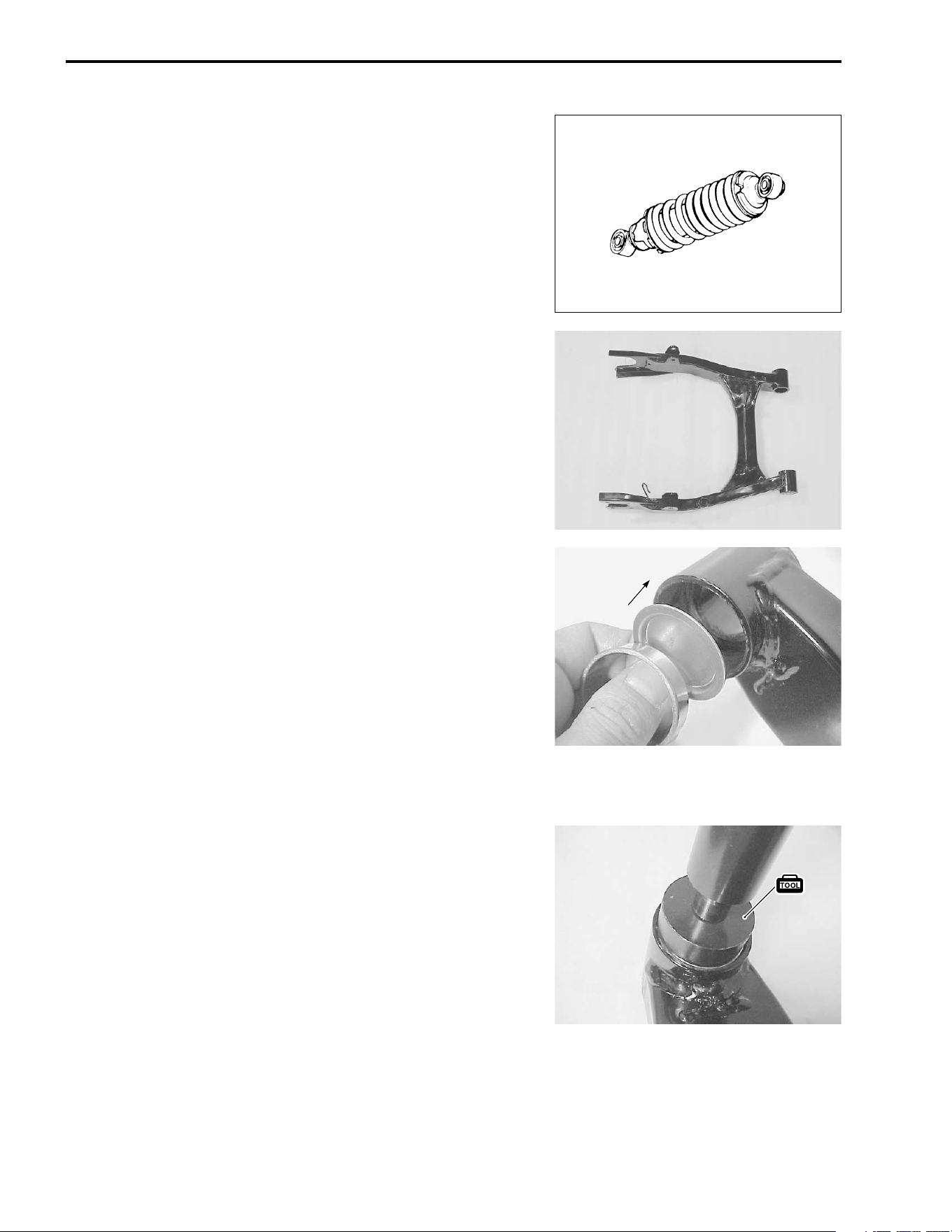
7-66 CHASSIS
REAR SHOCK ABSORBER
Inspect the rear shock absorber for oil leakage or damage. If any
damages are found, replace it with a new one.
SWINGARM
Inspect the suspension arm for distortion or damage. If any
damage are found, replace the swingarm with a new one.
REASSEMBLY AND REMOUNTING
Reassembly and remount the rear swingarm and suspension in
the reverse order of removal and disassembly. Pay attention to
the following points:
SWINGARM
• Install the swingarm bearing race and its plate to the swing-
arm by using the special tool.
* 09913-70210: Bearing installer set
NOTE:
When installing the bearing plate, make sure that the bulge of
bearing plate faces inside.
• Apply SUZUKI SUPER GREASE “A” to the swingarm bear-
ings and lips of dust seals, then install them into the swingarm
with the special tool.
+ 99000-25030: SUZUKI SUPER GREASE “A” (USA)
99000-25010: SUZUKI SUPER GREASE “A” (Others)
*09913-70210: Bearing installer set
• Install the spacers to the swingarm.
INSIDE
INSIDE
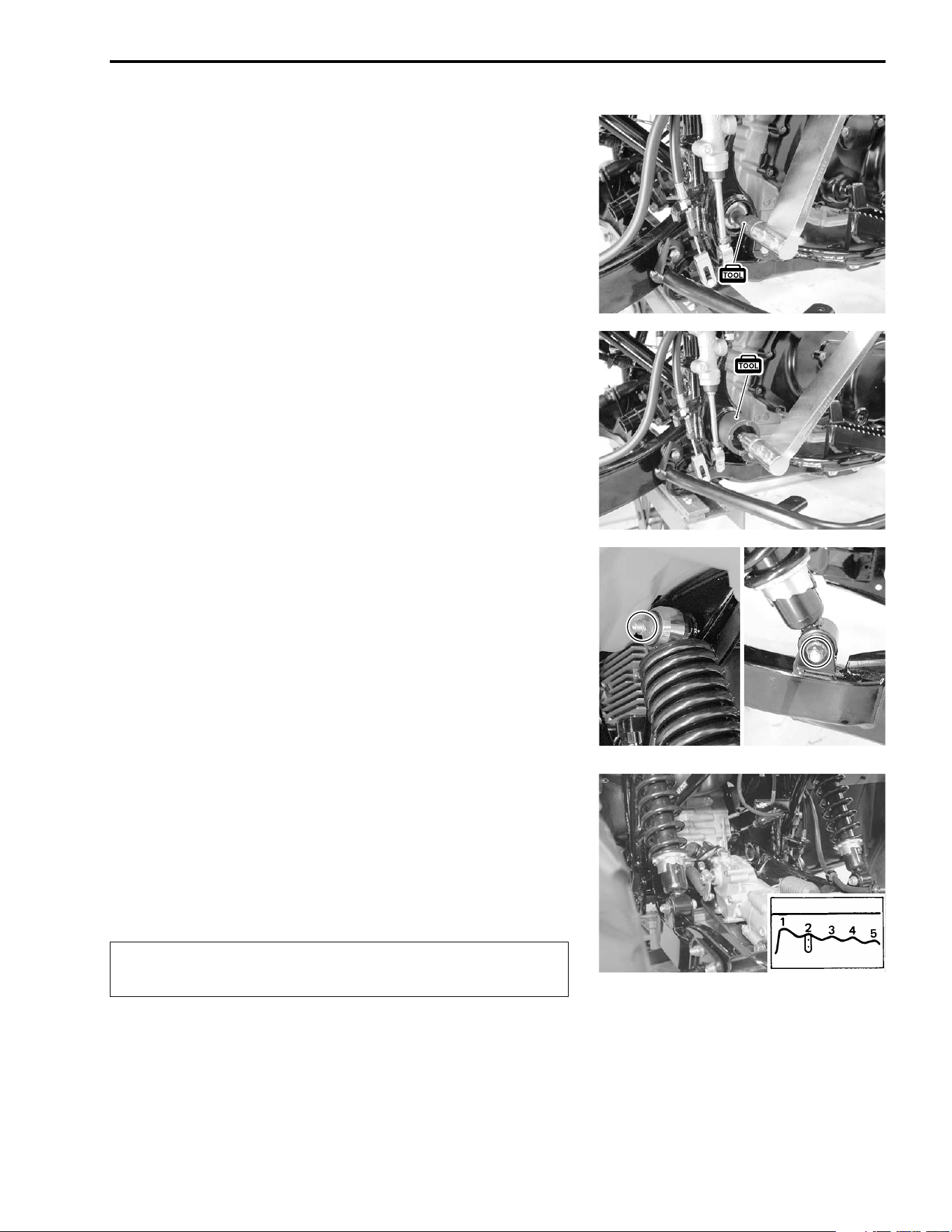
CHASSIS 7-67
• Tighten the swingarm pivot bolts temporarily.
• Tighten the left side swingarm pivot bolt to the specified
torque first, and then tighten the right side bolt with special
tool.
# Swingarm pivot bolt (LH): 100 N·m (10.0 kgf-m, 72.5 lb-ft)
Swingarm pivot bolt (RH): 9.5 N·m (0.95 kgf-m, 7.0 lb-ft)
* 09900-18710: Hexagon socket (12 mm)
• Tighten the swingarm pivot locknut to the specified torque
with the special tool.
# Swingarm pivot lock nut: 100 N·m (10.0 kgf-m, 72.5 lb-ft)
* 09900-14970: Swingarm pivot adjust wrench
NOTE:
After remounting the swingarm, inspect the swingarm whether it
moves smoothly.
• Install the rear shock absorbers (left and right).
• Tighten the rear shock absorber mounting bolts/nuts.
# Rear shock absorber mounting nut (upper) :
35 N·m (3.5 kgf-m, 25.5 lb-ft)
Rear shock absorber mounting bolt/nut (lower) :
60 N·m (6.0 kgf-m, 43.5 lb-ft)
NOTE:
When tightening the rear shock absorber mounting bolt/nut,
place 75 kg (165 lbs) of weight on the seat.
SPRING PRE-LOAD ADJUSTMENT
After installing the rear suspension, adjust the spring pre-load.
Position “1” provides the softest spring pre-load.
Position “5” provides the stiffest spring pre-load.
STD POSITION: “2”
&
Be sure to adjust the spring pre-load on the both sus-
pensions equally.
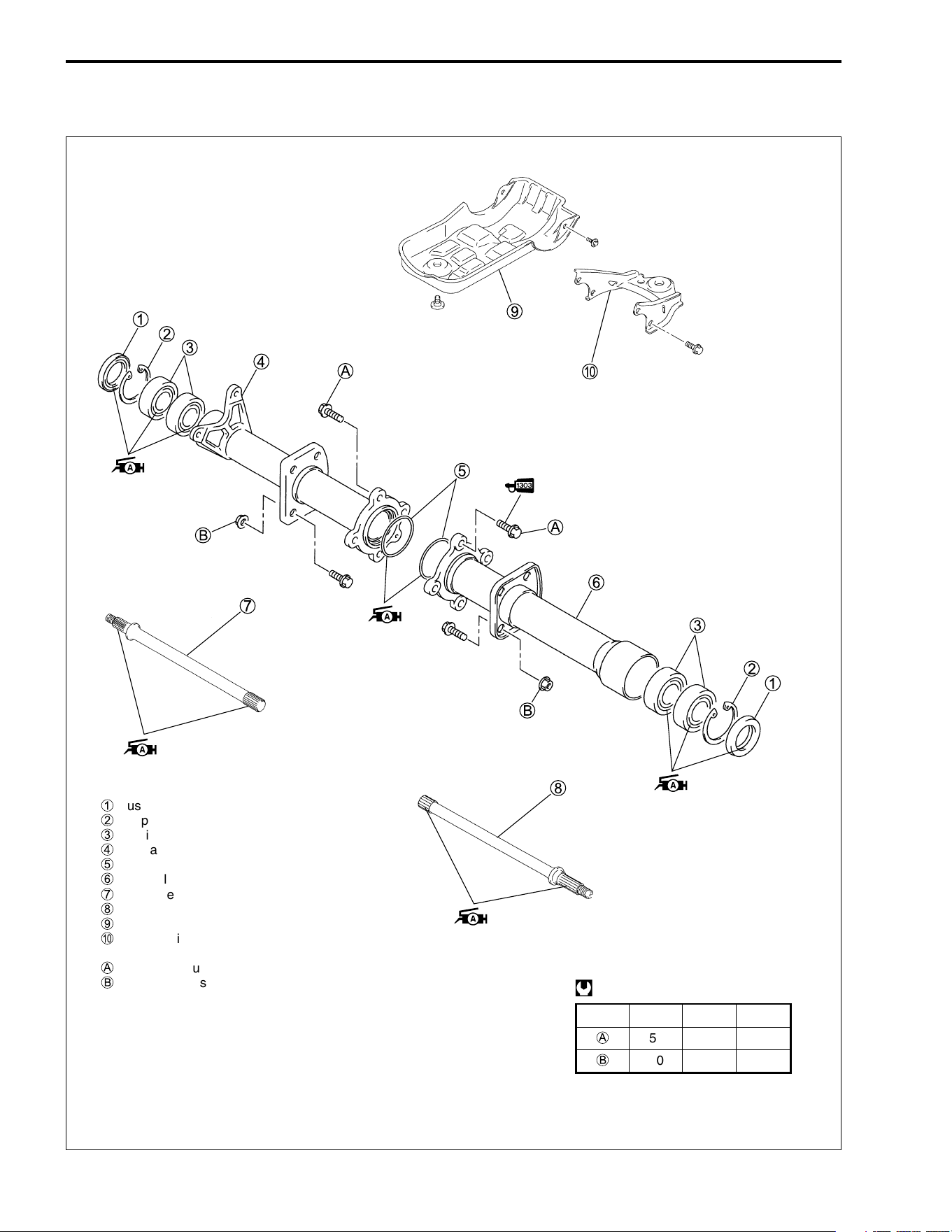
7-68 CHASSIS
REAR AXLE
CONSTRUCTION
ITEM N·m kgf
-
m lb-ft
A
55 5.5 40.0
B
60 6.0 43.5
@
1
Dust seal
2
Snap ring
3
Bearing
4
Rear axle housing (RH)
5
O-ring
6
Rear axle housing (LH)
7
Rear axle (RH)
8
Rear axle (LH)
9
Rear drive gear case cover
0
Trailer towing
A
Rear axle housing bolt
B
Rear axle housing mounting nut
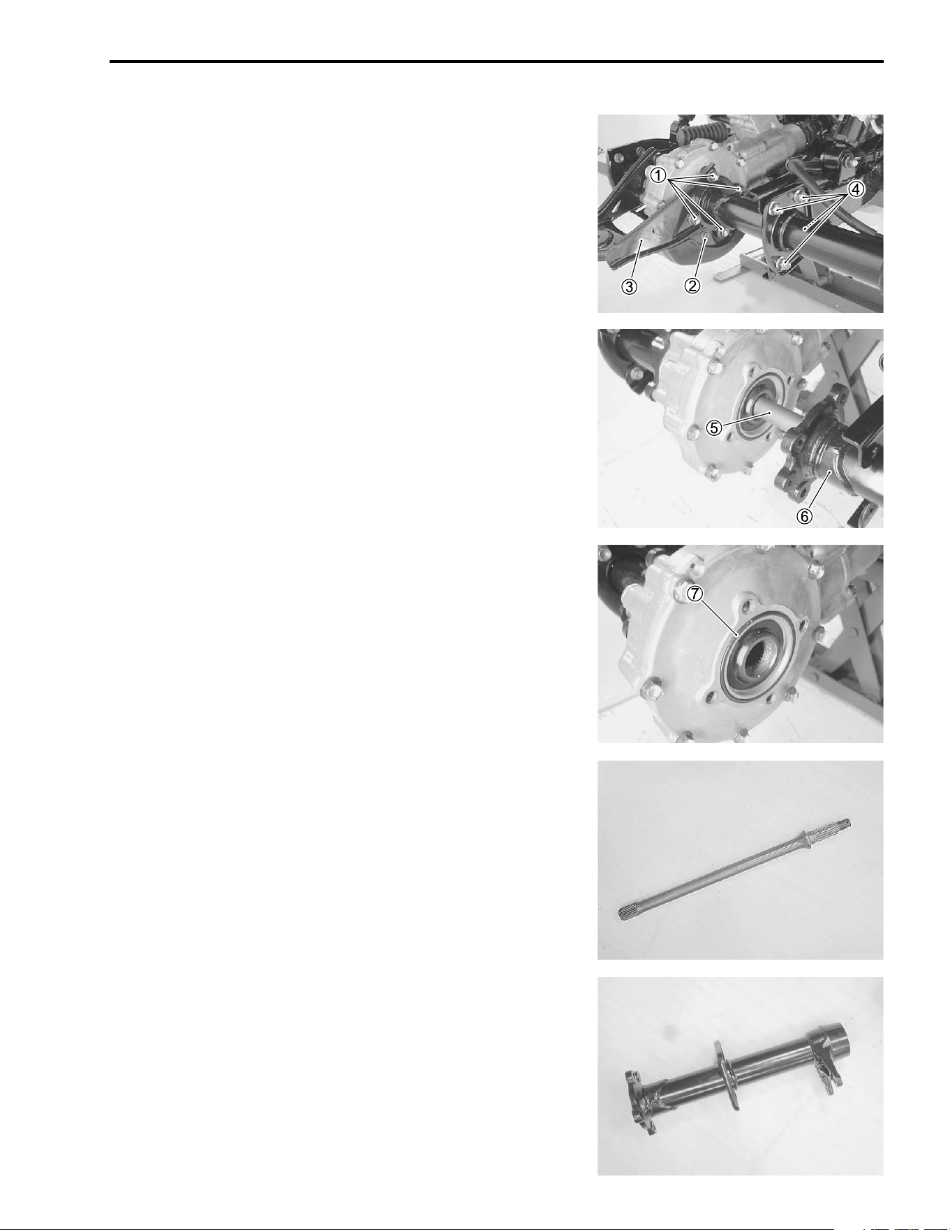
CHASSIS 7-69
REMOVAL
• Place the vehicle on level ground.
• Remove the rear wheel. (!7-11)
• Remove the rear caliper. (!7-51)
• Remove the rear wheel hub. (!7-57)
• Loosen the rear axle housing bolts
1.
• Remove the rear drive gear case cover bolts
2.
• Remove the trailer towing
3.
• Remove the swingarm bracket bolts and nuts
4.
• Remove the rear axle
5 and rear axle housing
6.
• Remove the O-ring
7.
INSPECTION AND DISASSEMBLY
REAR AXLE SHAFT
Inspect the rear axle shaft for distortion or damages. If any dam-
ages are found, replace the rear axle shaft with a new one.
REAR AXLE HOUSING
Inspect the rear axle housing for distortion or damages. If any
damages are found, replace the rear axle housing with a new
one.
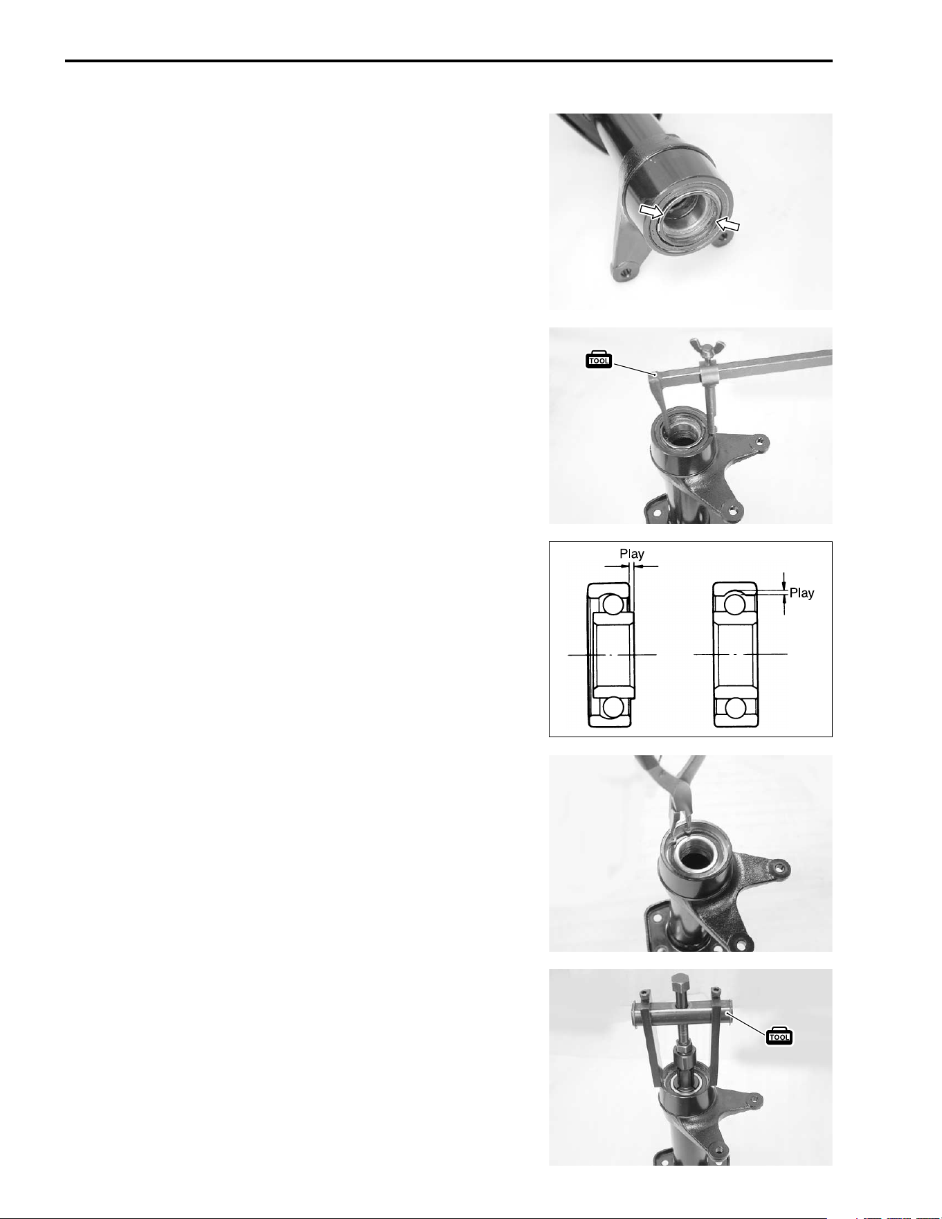
7-70 CHASSIS
DUST SEAL
Inspect the dust seal’s lip for wear or damage. If any damages
are found, replace the dust seal with a new one.
• Remove the dust seal using the special tool.
* 09913-50121: Oil seal remover
HUB BEARING
Inspect the inner race play of the hub bearing by hand while it is
in the rear axle housing.
Rotate the inner race by hand to inspect for abnormal noise and
smooth rotation. If there is anything unusual, replace the bearing
with a new one.
NOTE:
Make sure to check each bearing in the same manner.
• Remove the snap ring.
• Remove the hub bearings using the special tool.
* 09921-20240: Bearing remover set
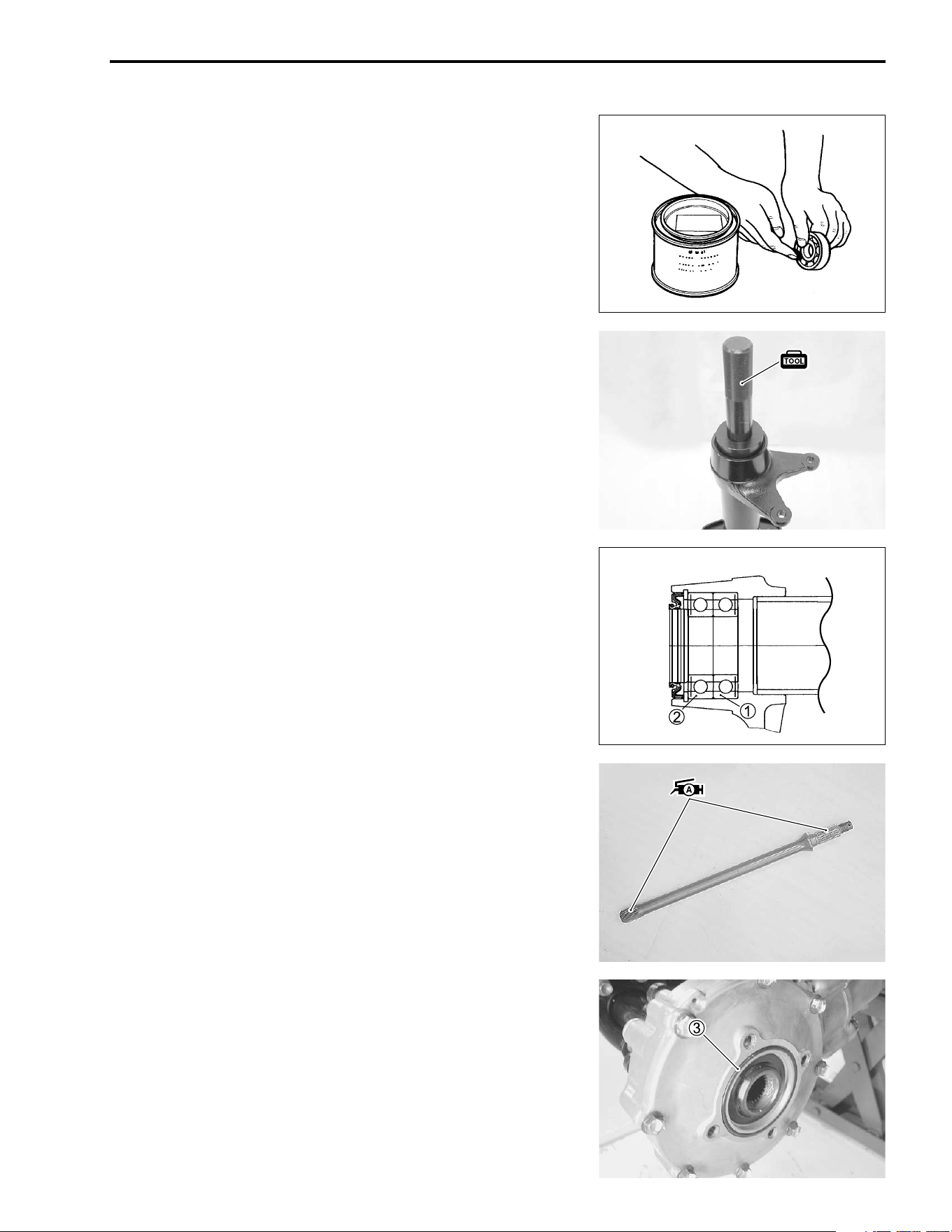
CHASSIS 7-71
REASSEMBLY AND REMOUNTING
Reassembly and remounting the rear axle in reverse order of
removal and disassmebly. Pay attention to the following points:
• Apply SUZUKI SUPER GREASE “A” to the hub bearings and
dust seals before installing them.
+ 99000-25030: SUZUKI SUPER GREASE “A” (USA)
99000-25010: SUZUKI SUPER GREASE “A” (Others)
• Install the hub bearings and dust seal with the special tool.
* 09913-70210: Bearing installer set
NOTE:
When installing the hub bearings to the axle housing, the sealed
cover of inner bearing
1 must face inside, and the sealed cover
of outer bearing
2 must face outside.
• Apply SUZUKI SUPER GREASE “A” to the rear axle shaft
spline.
+ 99000-25030: SUZUKI SUPER GREASE “A” (USA)
99000-25010: SUZUKI SUPER GREASE “A” (Others)
NOTE:
Overall length of RH axle shaft is shorter than LH axle shaft.
• Install the O-ring
3 to the rear drive gear case.
NOTE:
Before installing the O-ring
3, apply grease to it.
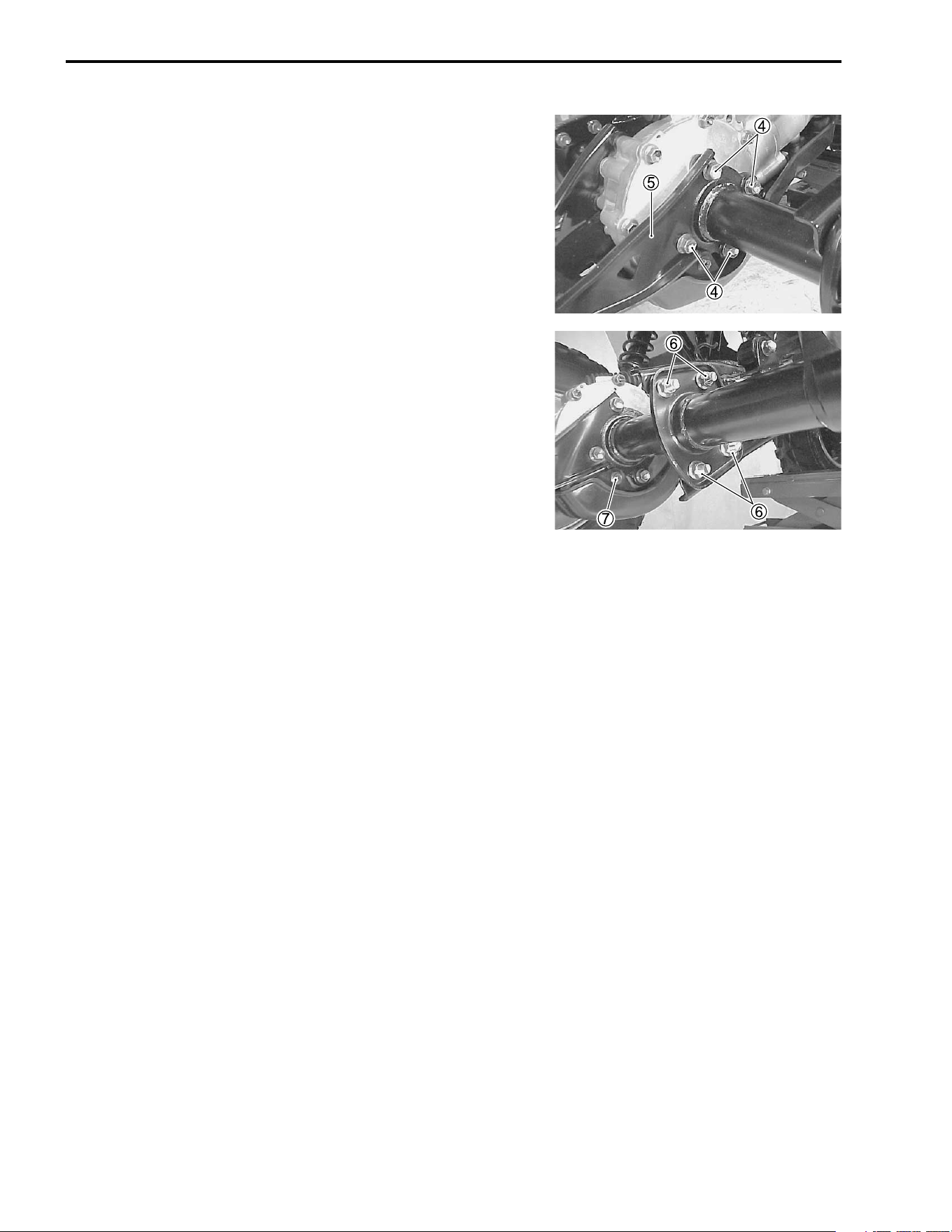
7-72 CHASSIS
• Install the rear axle shaft and rear axle housing to the rear
drive gear case.
• Apply THREAD LOCK SUPER “1303” to the rear axle hous-
ing bolts
4.
• Install the trailer towing
5 and tighten the rear axle housing
bolts
4 to the specified torque.
, 99000-32030: THREAD LOCK SUPER “1303”
# Rear axle housing bolt: 55 N·m (5.5 kgf-m, 40.0 lb-ft)
• Tighten the axle housing mounting bolts/nuts
6 to the speci-
fied torque.
# Axle housing mounting bolts/nuts:
60 N·m (6.0 kgf-m, 43.5 lb-ft)
• Tighten the final drive gear case cover bolts
7.
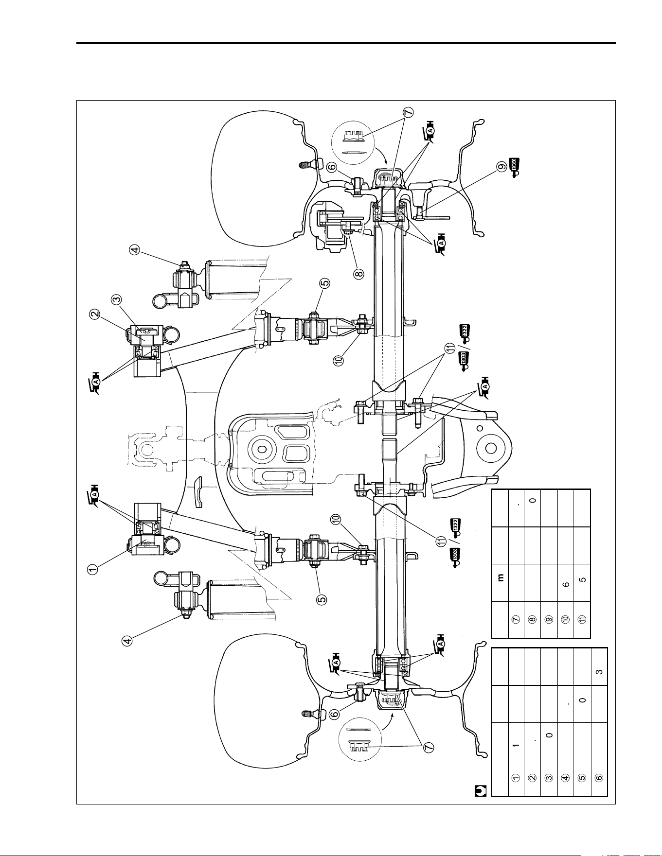
CHASSIS 7-73
REAR WHEEL, REAR BRAKE, REAR SUSPENSION, REAR SWIN-
GARM AND REAR AXLE SHAFT REASSEMBLING INFORMATION
ITEM N·m kgf-m lb-ft
1
100 10 72.5
2
9.5 0.95 7.0
3
100 10 72.5
4
35 3.5 25.5
5
60 6.0 43.5
6
50 5.0 36.0
@
ITEM N·m kgf-m lb-ft
7
110 11 79.5
8
32 3.2 23.0
9
23 2.3 16.5
0
60 6.0 43.5
A
55 5.5 40.0
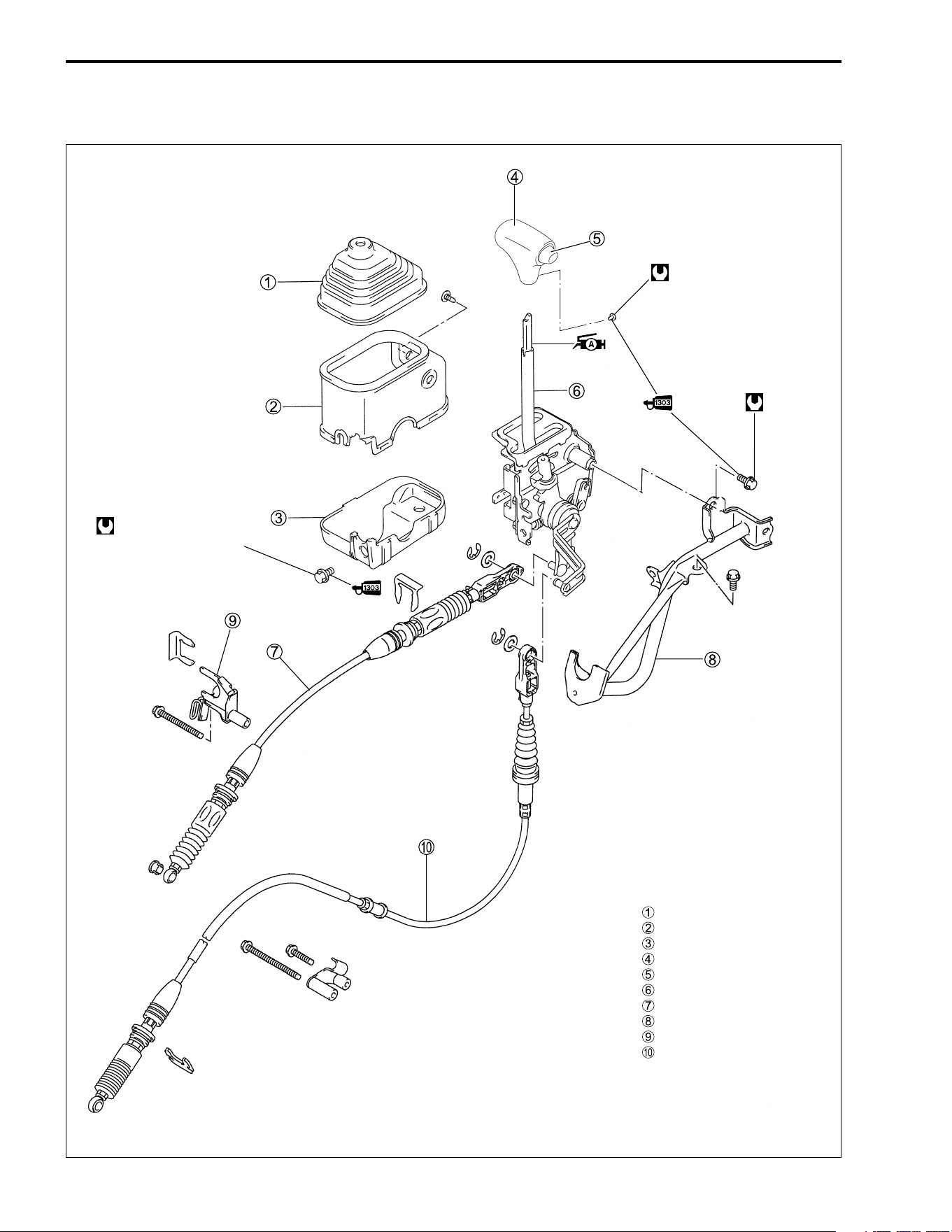
7-74 CHASSIS
GEARSHIFT LEVER
CONSTRUCTION
29 N·m
2.9 kgf-m,
21.0 lb-ft
2.0 N·m
(0.2 kgf-m, 1.5 lb-ft)
29 N·m
(2.9 kgf-m, 21.0 lb-ft)
Boot
Upper cover
Lower cover
Knob
Button
Gearshift lever assy
Reverse gear cable
Bracket
Cable stopper
Parking cable
( )
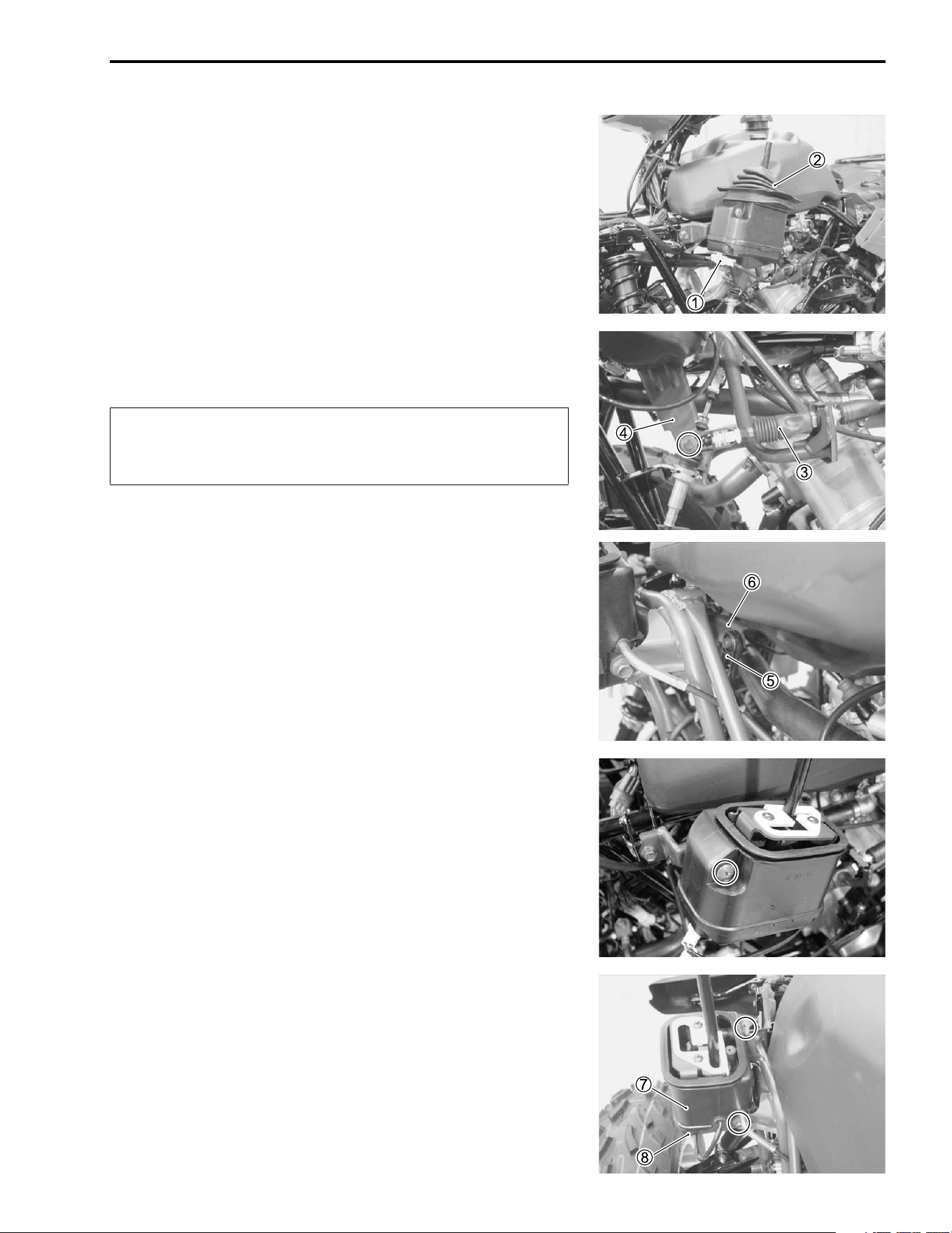
CHASSIS 7-75
REMOVAL AND DISASSEMBLY
• Remove the front fender. (! 7-6)
• Disconnect the parking switch coupler
1.
• Remove the boot
2.
• Remove the E-ring and disconnect the reverse gear cable
3
from the reverse arm
4.
$
• Disconnect the parking cable
5 from the parking arm
6.
• Remove the screw.
• Loosen the mounting bolts.
• Remove the upper
7 and lower cover
8.
Do not apply lateral force to the cable end. Excessive
bending of cable may result in damage of flexible joint
of cable
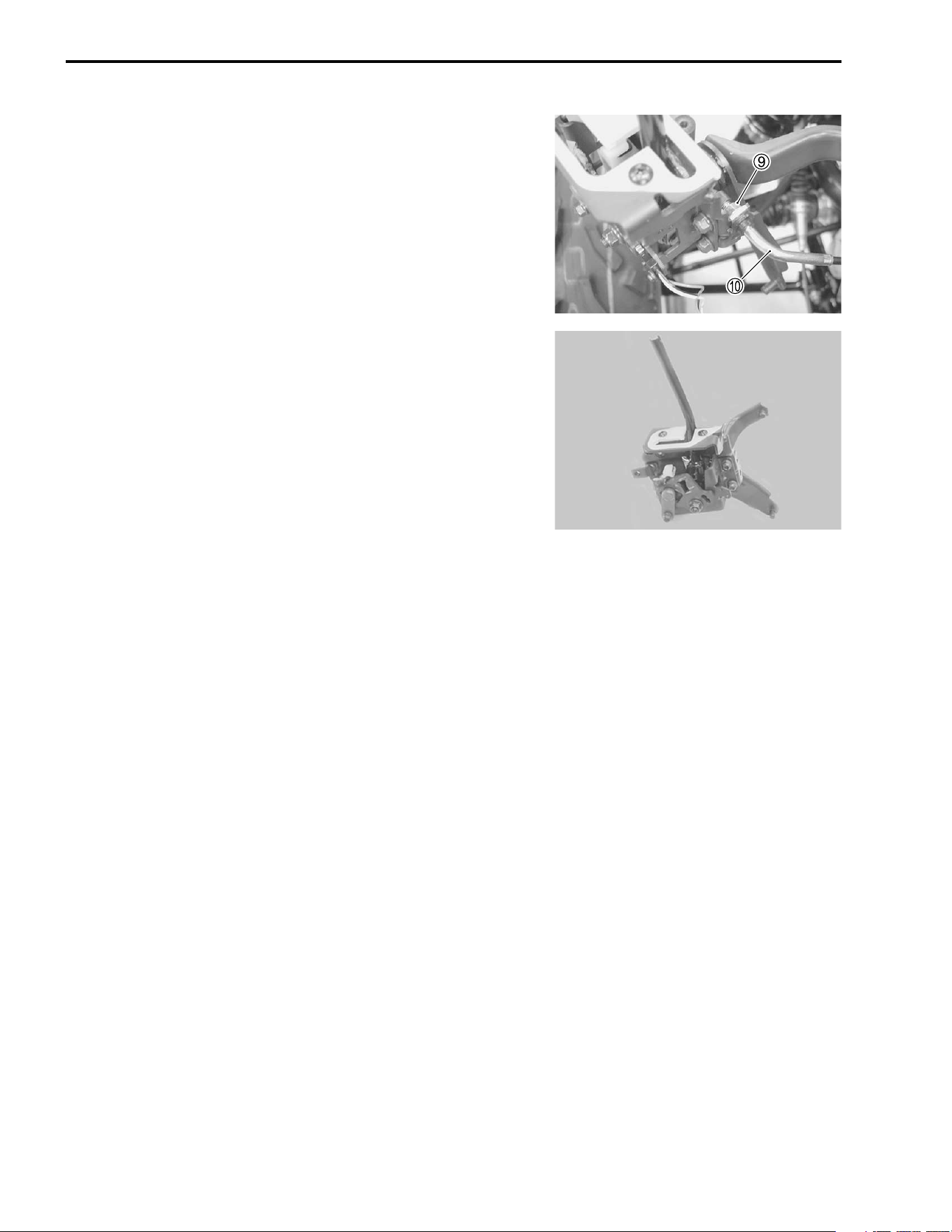
7-76 CHASSIS
• Loosen the locknut
9 and disconnect the parking interlock
cable
0.
• Remove the gearshift lever assembly.
INSPECTION
GEARSHIFT LEVER ASSEMBLY
Inspect the gearshift lever assembly for wear or damage. If any
damage are found, replace the gear shift lever assembly.
NOTE:
Do not disassemble the gearshift lever assembly.
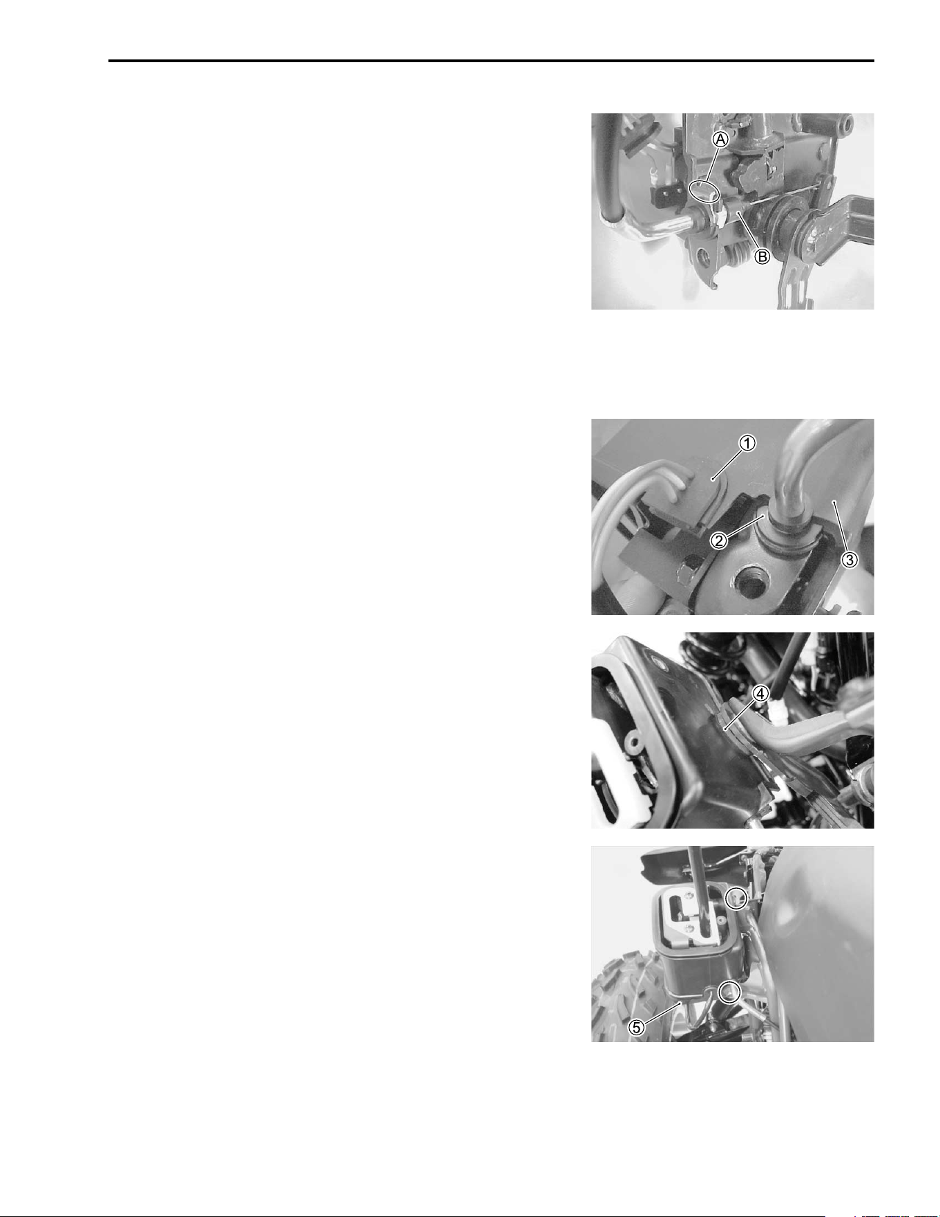
CHASSIS 7-77
REASSEMBLY AND REMOUNTING
Reassemble and remount the gearshift lever in the reverse
order of removal and disassembly. Pay attention to the following
points:
• Apply SUZUKI SUPER GREASE “A” to the each pivot, sliding
area and lock pins.
+ 99000-25030: SUZUKI SUPER GREASE “A” (USA)
99000-25010: SUZUKI SUPER GREASE “A” (Others)
• Install the parking switch.
• Install the parking interlock cable with the cable’s claw
A up.
NOTE:
Make sure that the boot
B is fitted securely.
• Install the gearshift covers to the gearshift lever assembly.
• Fit the parking switch read wire’s grommet
1 and parking
interlock cable’s dust cover
2 to the gearshift upper covers
3.
• Fit the gearshift covers to the dust seal
4 on the gearshift
arm pivot.
• Install the lower cover
5.
• Install the gearshift lever assembly to the frame bracket.
• Apply THREAD LOCK SUPER “1303” to the gearshift lever
assembly mounting bolts.
, 99000-32030: THREAD LOCK SUPER “1303”
# Gearshift lever assembly mounting bolt:
29 N·m (2.9 kgf-m, 21.0 lb-ft)
• Connect the each cables to the gearshift lever assembly.
(!7-79 and 7-81)
• Install the front fender. (!7-6)
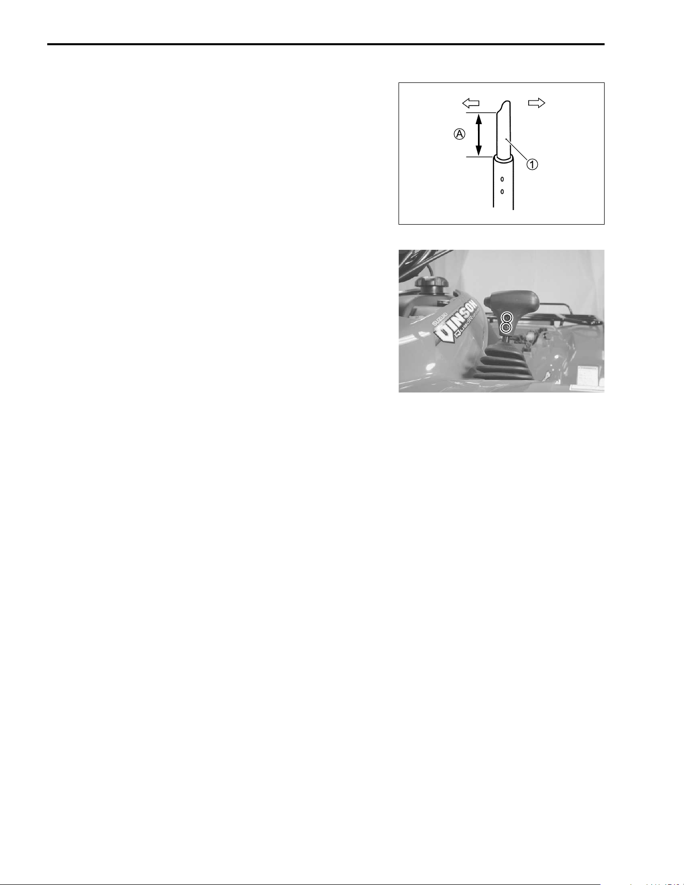
7-78 CHASSIS
• Apply SUZUKI SUPER GREASE “A” to the gearshift lever
rod.
+ 99000-25030: SUZUKI SUPER GREASE “A” (USA)
99000-25010: SUZUKI SUPER GREASE “A” (Others)
• Turn the gearshift lever rod
1 so that the rod length
A would
be 23 mm (0.9 in) as shown in the illustration.
NOTE:
The slant on the shift lever rod must be faced to the right side of
the vehicle.
• Install the shift knob to the gearshift lever with the button
depressed.
, 99000-32030: THREAD LOCK SUPER “1303”
• Tighten the screws to the specified torque.
# Gearshift lever screw: 2.0 N·m (0.2 kgf-m, 1.5 lb-ft)
Left
Right
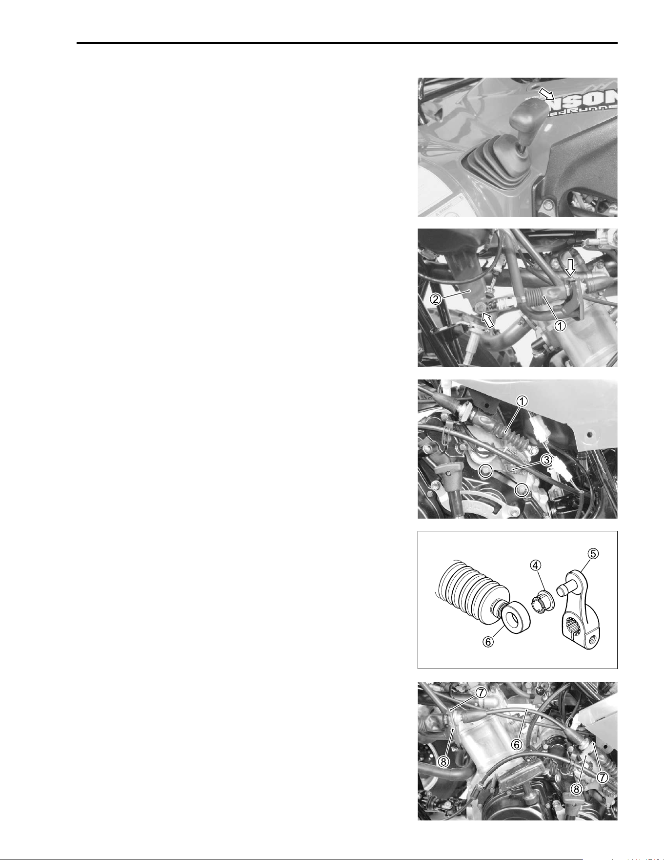
CHASSIS 7-79
CABLES
REMOVAL AND INSTALLATION
REVERSE GEAR CABLE
Before removing the reverse gear cable, keep the gearshift lever
in the “R” position.
• Remove the tank covers, left inner fender and left mud guard.
(!7-5 to -8)
• Disconnect the reverse gear cable
1 from the reverse arm
2
by removing the E-ring and clip.
• Remove the reverse switch
3 and clip.
• Remove the reverse gear cable
1 with the reverse gear arm.
• Release the cable adjuster lock. (!7-83)
• Install the busing
4 to the reverse gear arm
5.
• Connect the reverse gear arm
5 to the reverse gear cable
6.
• Install the reverse gear cable
6 and clips
7 to the stoppers
8.
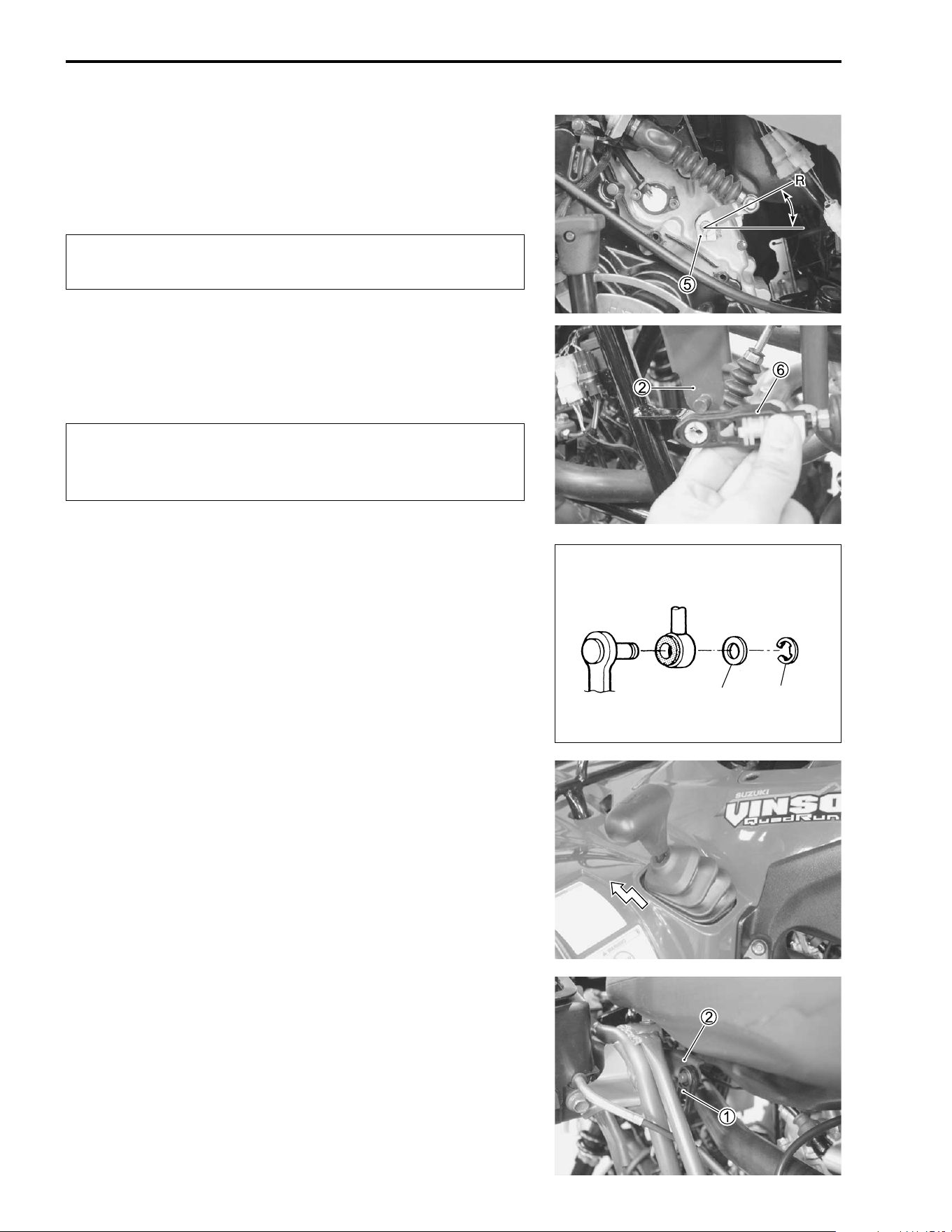
7-80 CHASSIS
• Install the reverse gear arm
5 onto its shaft so that the setting
angle becomes approx. 42° from the horizontal to the “R”
position.
• Install the reverse switch.
$
• Install the reverse gear cable
6, washer and E-ring to the
reverse arm
2.
• Adjust the cable play. (!7-83)
$
PARKING CABLE
Before removing the parking cable, keep the gearshift lever in
the “P” position.
• Remove the tank covers, left inner fender and left mud guard.
(!7-5 to -8)
• Disconnect the parking cable
1 from the parking arm
2.
Make sure the installation angle of the reverse gear
arm is accurate.
Do not apply lateral force to the cable end. Excessive
bending of cable may result in damage of flexible joint
of cable
Washer E-ring
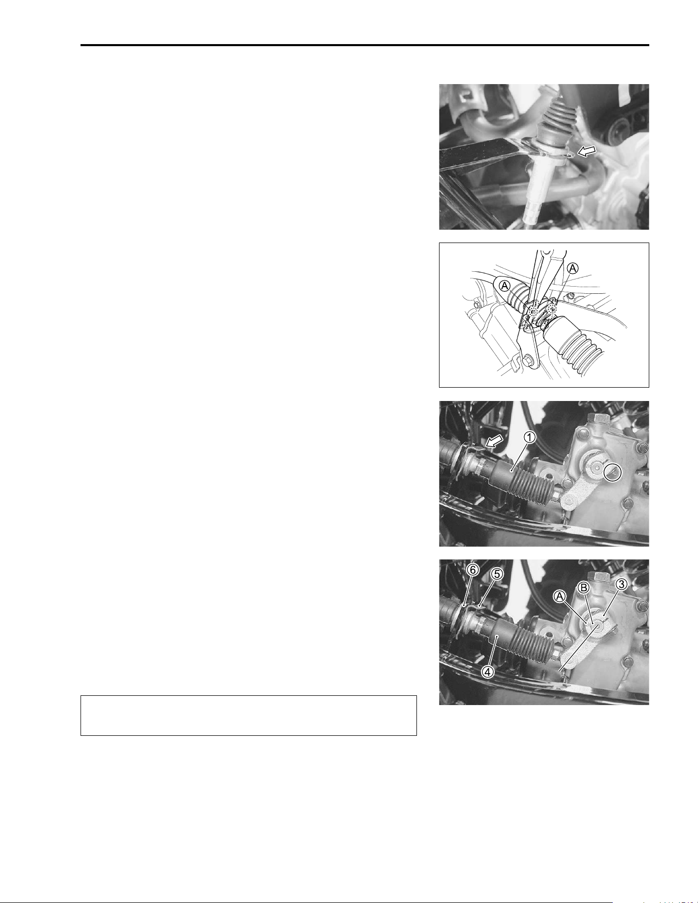
CHASSIS 7-81
• Remove the clip.
NOTE:
Flatten the locked parts
A with a long nose pliers.
• Remove the clip.
• Remove the parking cable
1 with the parking cam arm.
• Release the cable adjuster lock. (!7-83)
• Connect the parking cam arm
3 to the parking cable
4.
• Align the punched mark
A on the parking cam arm
3 with the
punched mark
B on the parking cam shaft.
• Install the parking cable
4 and clip
5 to the stopper
6 on the
swingarm.
• Make sure that the parking cam arm is in “P” position.
$
Make sure that the installation angle of the parking
lever is accurate.
P
P
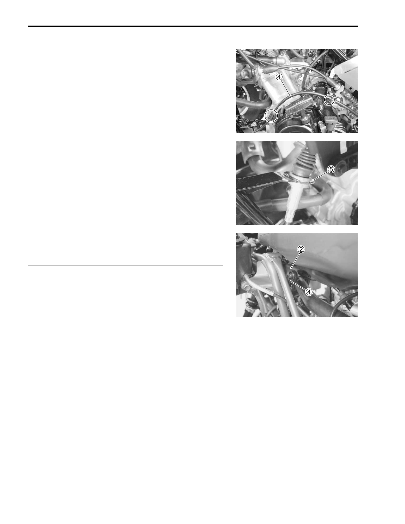
7-82 CHASSIS
• Pass the parking cable
4 through the guides.
• Install the clip
5.
• Install the parking cable
4 to the parking arm
2.
• Adjust the cable play. (!7-83)
$
Do not apply lateral force to the cable end. Excessive
bending of cable may result in damage of flexible joint
of cable
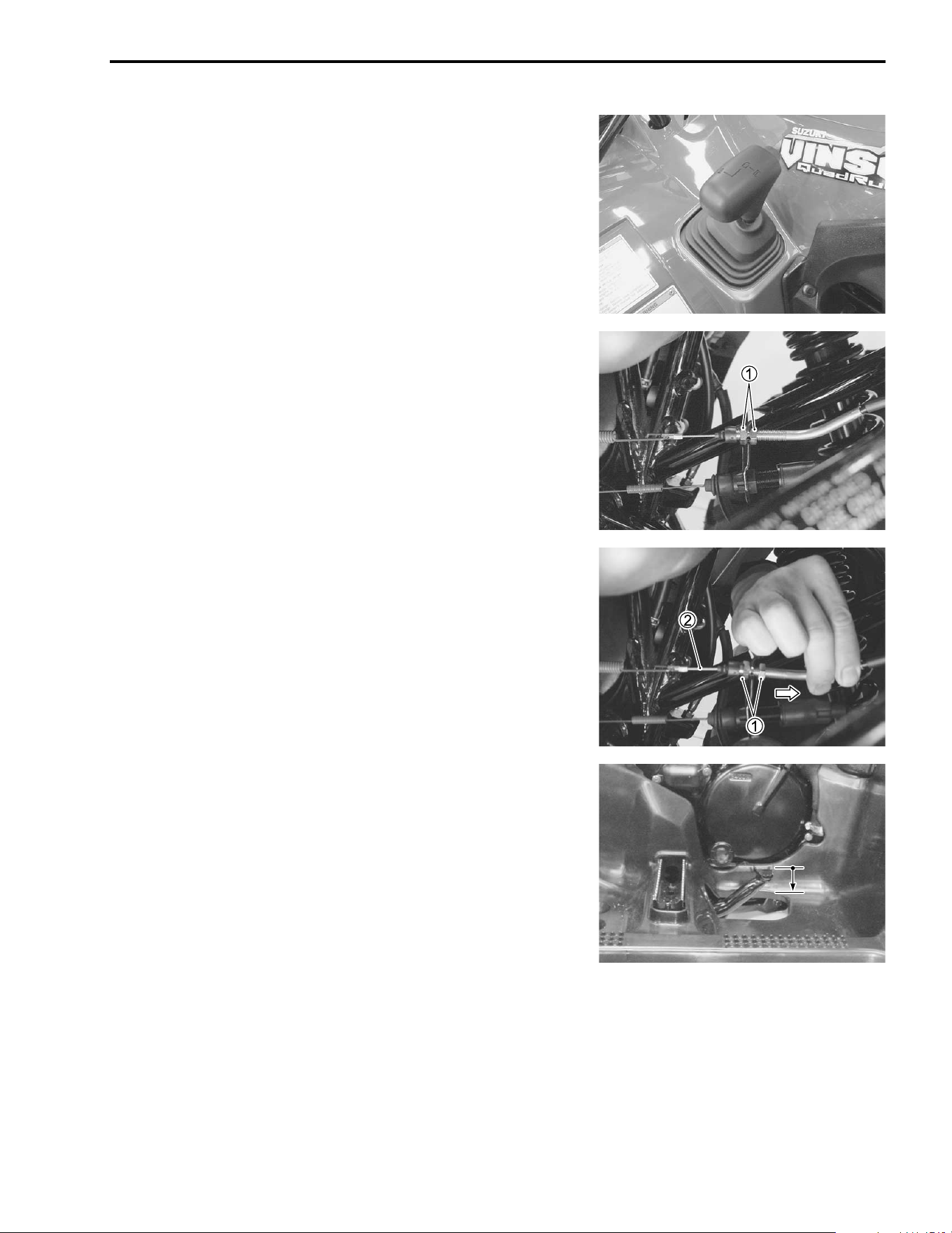
CHASSIS 7-83
CABLE PLAY ADJUSTMENT
PARKING INTERLOCK CABLE
Before adjusting the parking interlock cable play, adjust the rear
brake pedal height and rear brake lever play properly. (!2-
15)
• Shift the shift lever into “D”.
• Loosen the locknuts
1.
• Tighten the locknuts
1 with pulling the parking inter lock
cable
2 lightly.
• Make sure that the shift lever could be shifted into “P” when
the rear brake pedal is depressed approx. 20 mm (0.78 in).
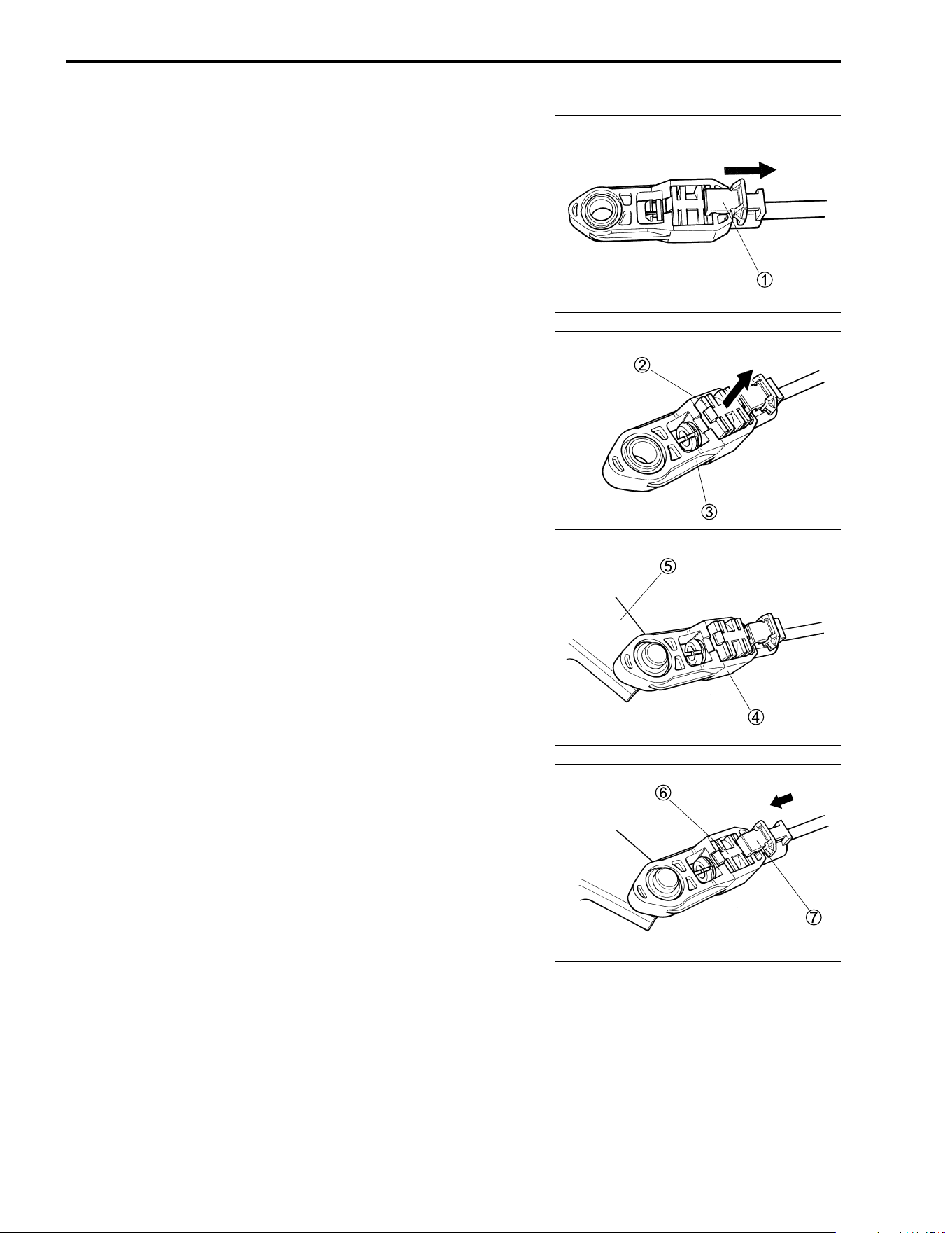
7-84 CHASSIS
REVERSE GEAR CABLE AND PARKING CABLE
Before installing the cable, release the cable adjuster lock.
• Slide the lock cover
1 on the cable adjuster.
• Push out the lock piece
2 to an extent where the adjuster
3
slides smoothly.
NOTE:
Do not remove the lock piece
2 from the cable adjuster.
• Fit the cable adjuster
4 onto the selection arm
5 securely.
NOTE:
Before fitting the cable adjuster, make sure that the gear shift
lever position is same as the selection lever arm position.
• Push the lock piece
6 into the cable adjuster.
• Slide the lock cover
7.

8
ELECTRICAL SYSTEM 8-1
CONTENTS
ELECTRICAL SYSTEM
CAUTIONS IN SERVICING ................................................................8- 2
CONNECTORS ............................................................................8- 2
COUPLERS ..................................................................................8- 2
CLAMPS ......................................................................................8- 2
FUSES .......................................................................................... 8- 2
SEMI-CONDUCTOR EQUIPPED PARTS ...................................8- 2
BATTERY .....................................................................................8- 3
CONNECTING THE BATTERY ...................................................8- 3
WIRING PROCEDURE ................................................................8- 3
USING THE MULTI CIRCUIT TESTER .......................................8- 3
LOCATION OF ELECTRICAL COMPONENTS .................................8- 4
CHARGING SYSTEM .........................................................................8- 6
TROUBLESHOOTING ................................................................. 8- 6
INSPECTION ................................................................................8- 8
STARTER SYSTEM ............................................................................8-11
TROUBLESHOOTING .................................................................8-11
STARTER MOTOR REMOVAL AND DISASSEMBLY ...............8-12
STARTER MOTOR INSPECTION ............................................... 8-13
STARTER MOTOR REASSEMBLY AND REMOUNTING .......... 8-14
STARTER RELAY INSPECTION ................................................8-15
NEUTRAL RELAY INSPECTION ................................................8-16
PARKING BRAKE SWITCH ........................................................8-16
IGNITION SYSTEM .............................................................................8-17
TROUBLESHOOTING .................................................................8-17
INSPECTION ................................................................................8-19
2WD/4WD SELECTING SYSTEM ......................................................8-21
DESCRIPTION .............................................................................8-21
TROUBLESHOOTING .................................................................8-22
INSPECTION ................................................................................8-23
SPEEDOMETER .................................................................................8-25
PARTS NAMES ...........................................................................8-25
OPERATING PROCEDURE ........................................................8-26
INSPECTION ................................................................................8-28
LAMPS ................................................................................................8-30
HEADLIGHT AND AUXILIARY LIGHT ........................................8-30
BRAKE LIGHT/TAILLIGHT .........................................................8-32
SWITCHES .........................................................................................8-33
BATTERY ...........................................................................................8-35
SPECIFICATIONS .......................................................................8-35
INITIAL CHARGING ....................................................................8-35
SERVICING ..................................................................................8-37
RECHARGING OPERATION .......................................................8-37
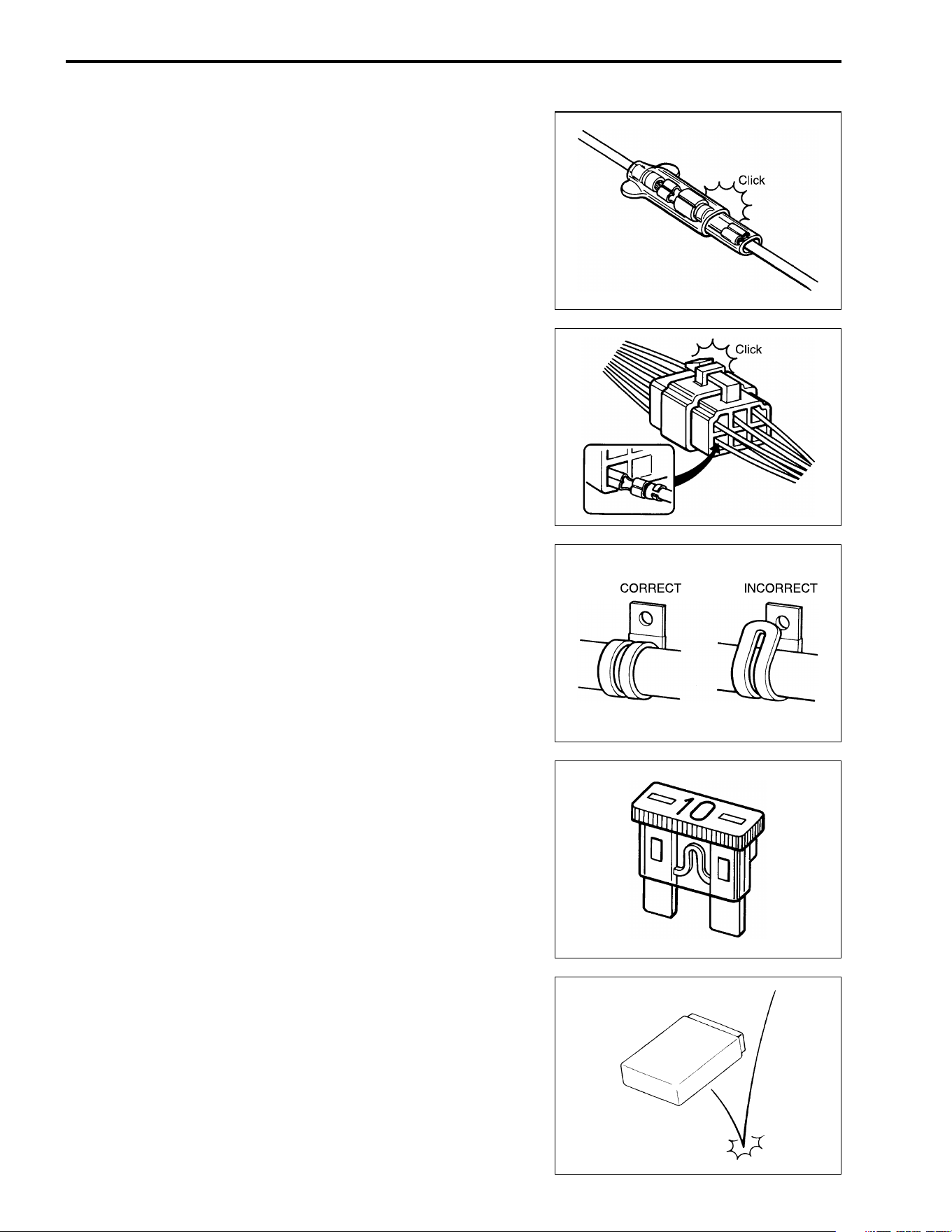
8-2 ELECTRICAL SYSTEM
CAUTIONS IN SERVICING
CONNECTORS
• When disconnecting a connector, be sure to hold the termi-
nals; do not pull the lead wires.
• When connecting a connector, push it in so it is firmly
attached.
• Inspect the connector for corrosion, contamination and any
breakage in the cover.
COUPLERS
• With a lock-type coupler, be sure to release the lock before
disconnecting it. When connecting a coupler, push it in until
the lock clicks shut.
• When disconnecting a coupler, be sure to hold the coupler; do
not pull the lead wires.
• Inspect each terminal on the coupler for looseness or bends.
• Inspect each terminal for corrosion and contamination.
CLAMPS
• Refer to the “WIRE HARNESS ROUTING” section for proper
clamping procedures. (!9-12 to 9-13)
• Bend the clamp properly, as shown in the illustration.
• When clamping the wire harness, do not allow it to hang
down.
• Do not use wire or any substitutes for the band-type clamp.
FUSES
• When a fuse blows, always investigate the cause, correct the
problem, and then replace the fuse.
• Do not use a fuse of a different capacity.
• Do not use any substitutes for the fuse (e.g., wire).
SEMI-CONDUCTOR EQUIPPED PARTS
• Do not drop any part that contains a semi-conductor (e.g.,
CDI unit, regulator/rectifier).
• When inspecting the part, follow the inspection instructions
carefully. Neglecting proper procedures may cause this part
to be damaged.
INCORRECT
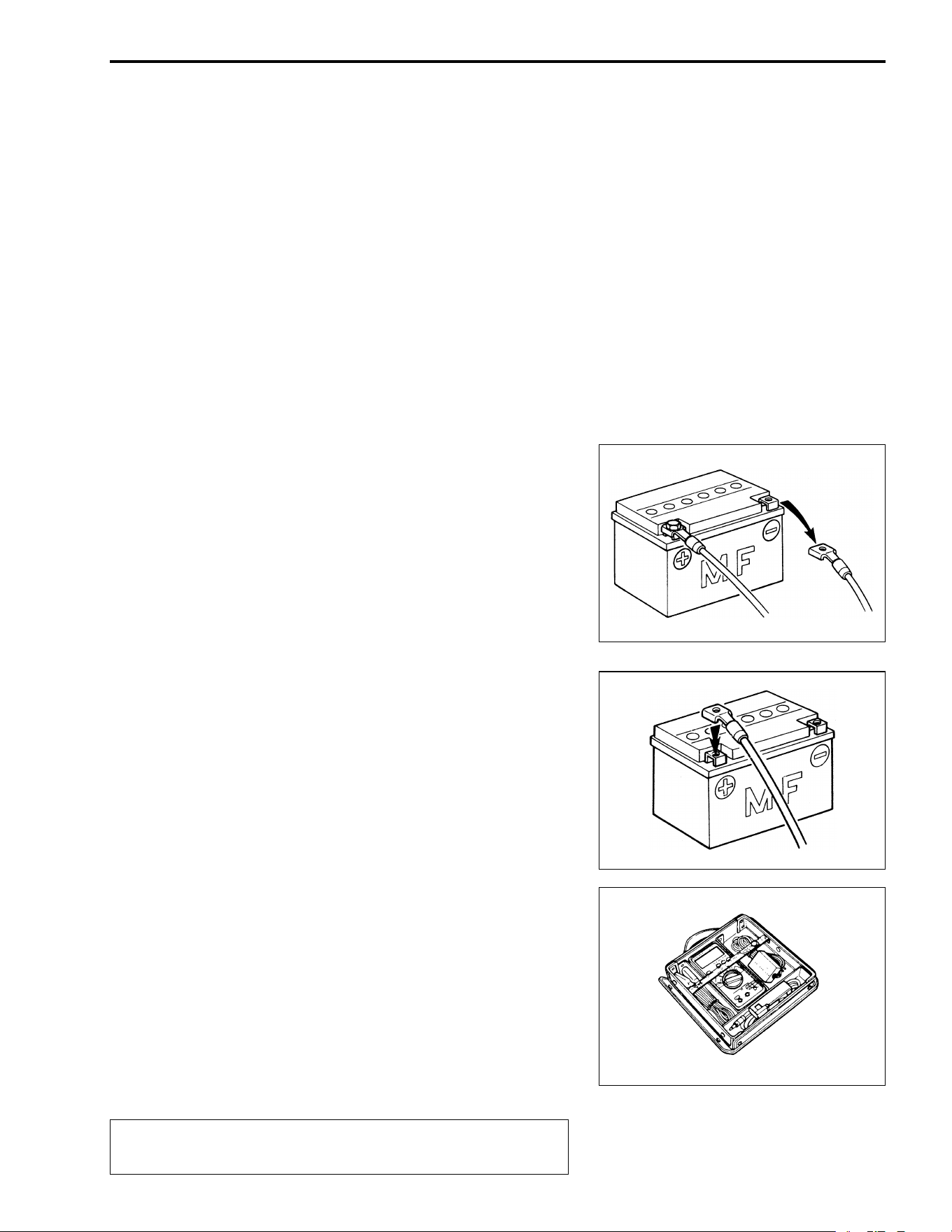
ELECTRICAL SYSTEM 8-3
BATTERY
• The MF battery used in this vehicle does not require mainte-
nance (e.g., electrolyte level inspection, distilled water replen-
ishment).
• During normal charging, no hydrogen gas is produced. How-
ever, if the battery is overcharged, hydrogen gas may be pro-
duced. Therefore, be sure there are no fire or spark sources
(e.g., short circuit) nearby when charging the battery.
• Be sure to recharge the battery in a well-ventilated and open
area.
• Note that the charging system for the MF battery is different
from that of a conventional battery. Do not replace the MF
battery with a conventional battery.
CONNECTING THE BATTERY
• When disconnecting terminals from the battery for disassem-
bly or servicing, be sure to disconnect the
- battery lead
wire, first.
• When connecting the battery lead wires, be sure to connect
the
+ battery lead wire, first.
• If the terminal is corroded, remove the battery, pour warm
water over it and clean it with a wire brush.
• After connecting the battery, apply a light coat of grease to the
battery terminals.
• Install the cover over the
+ battery terminal.
WIRING PROCEDURE
• Properly route the wire harness according to the “WIRE
ROUTING” section. (!9-12 to 9-13)
USING THE MULTI CIRCUIT TESTER
• Properly use the multi circuit tester
+ and
- probes.
Improper use can cause damage to the vehicle and tester.
• If the voltage and current values are not known, begin mea-
suring in the highest range.
• When measuring the resistance, make sure no voltage is
applied. If voltage is applied, the tester will be damaged.
• After using the tester, be sure to turn the switch to the OFF
position.
"
Before using the multi circuit tester, read its instruc-
tion manual.
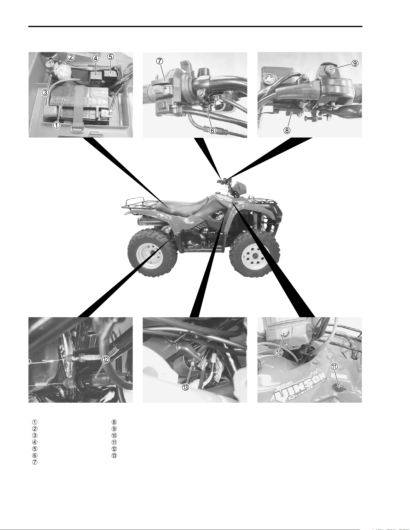
8-4 ELECTRICAL SYSTEM
LOCATION OF ELECTRICAL COMPONENTS
Battery
Main fuse
Starter relay
Fuse box
Neutral relay
Parking brake switch
Handlebar switch (L)
Front brake switch
2WD/4WD selection button
Ignition switch
Power source
Rear brake switch
Ignition coil
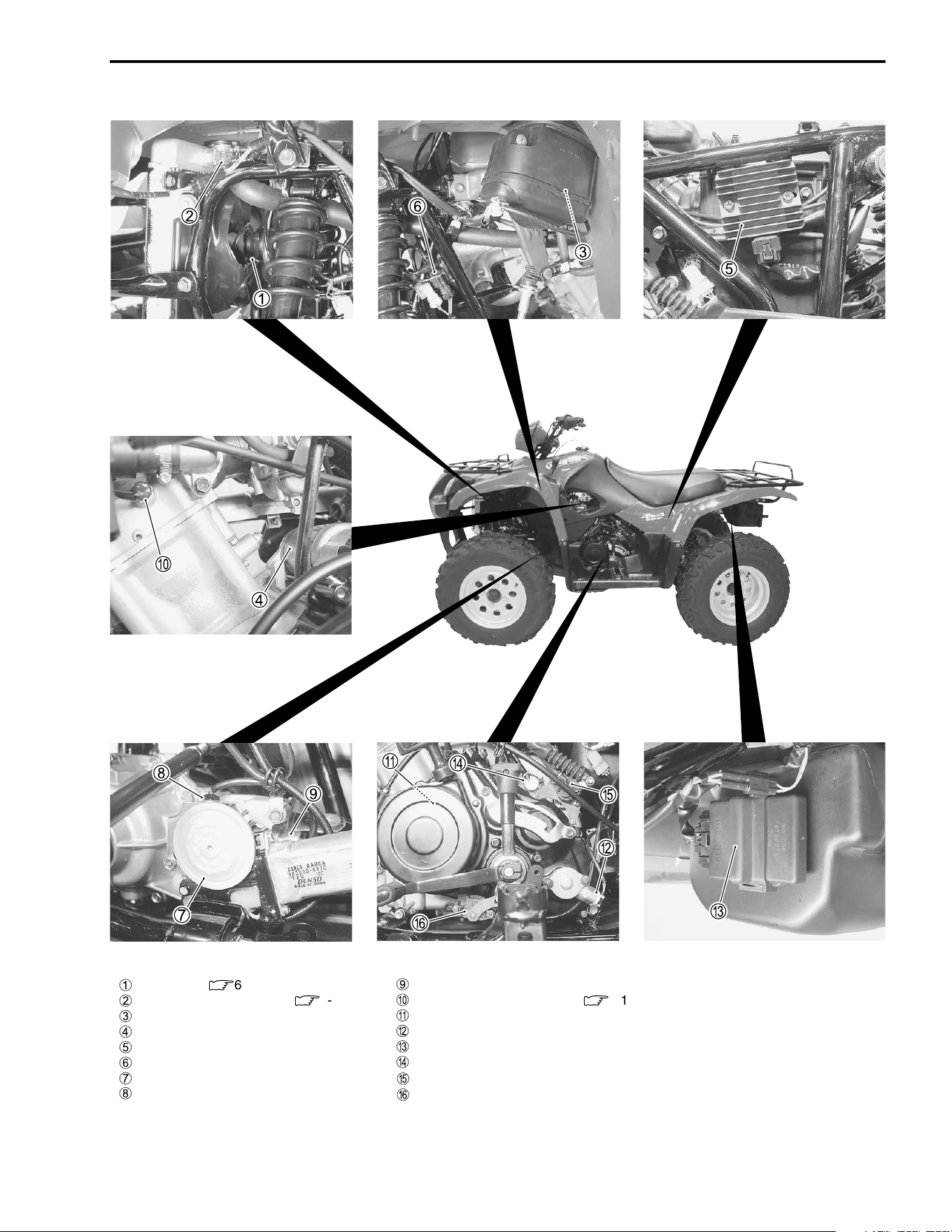
ELECTRICAL SYSTEM 8-5
Cooling fan (
:
6-7)
Cooling fan thermo-switch (
:
6-9)
Parking position switch
Starter motor
Regulator/rectifier
2WD/4WD selecting relay
2WD/4WD motor
4WD switch
2WD switch
Engine coolant temp. switch (
:
6-10)
Generator
Speed sensor
CDI unit
Neutral switch
Reverse switch
Gear switch
8-6 ELECTRICAL SYSTEM
CHARGING SYSTEM
TROUBLESHOOTING
Generator
Regulator/rectifier
Ignition switch
Main fuse
Battery
Load
No accessories
No current leaks
Incorrect
Continued on next page
• Remove accessories
• Short circuit of wire harness
• Faulty electrical equipment
• Faulty battery
• Abnormal driving condition
Battery runs down quickly.
Check accessories which use excessive
amounts of electricity.
Check the battery for current leaks.
(
:
8-8)
Measure the charging voltage between
the battery terminals. (
:
8-8)
Correct
Current leaks
Accessories
are installed
ELECTRICAL SYSTEM 8-7
• Faulty generator coil or
disconnected lead wires
• Faulty generator
• Faulty regulator/rectifier
Measure the continuity of the generator coil.
(
:
8-9)
Measure the generator no-load voltage.
(
:
8-9)
Continuity
Correct
Inspect the regulator/rectifier.
(
:
8-10)
Correct
Inspect the wires.
Correct
Incorrect
No continuity
Incorrect
Incorrect
• Short circuit of wire
harness
• Poor contact of coupler
• Faulty battery
Battery overcharges
• Faulty regulator/rectifier
• Faulty battery
• Poor contact of generator lead wire coupler
Others
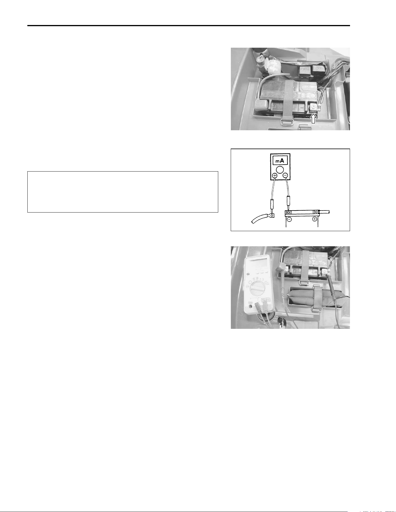
8-8 ELECTRICAL SYSTEM
INSPECTION
BATTERY CURRENT LEAKAGE
• Remove the seat. (! 7-4)
• Turn the ignition switch to the “OFF” position.
• Disconnect the
- battery lead wire.
Measure the current between
- battery terminal and the
- bat-
tery lead wire using the multi circuit tester. If the reading
exceeds the specified value, leakage is evident.
# 09900-25008: Multi circuit tester set
$ Tester knob indication: Current (%, 20 mA)
& Battery current (leak): Under 2.5 mA
"
When checking to find the excessive current leakage, remove
the couplers and connectors, one by one, checking each part.
REGULATED VOLTAGE
• Remove the seat. (! 7-4)
• Start the engine, turn the ignition switch to AUX (') and the
dimmer switch to HI and run the engine at 5 000 r/min.
Measure the DC voltage between the
+ and
- battery termi-
nals using the multi circuit tester. If the voltage is not within the
specified value, inspect the generator and regulator/rectifier.
(!8-9 and 8-10)
NOTE:
When making this test, be sure that the battery is in fully-
charged condition.
# 09900-25008: Multi circuit tester set
( Tester knob indication: Voltage (%)
& Regulated voltage: 14.0 – 15.5 V at 5 000 r/min
* Because the current leak might be large, turn the
tester to the high range first to avoid tester damage.
* Do not turn the ignition switch to the “ON” position
when measuring current.
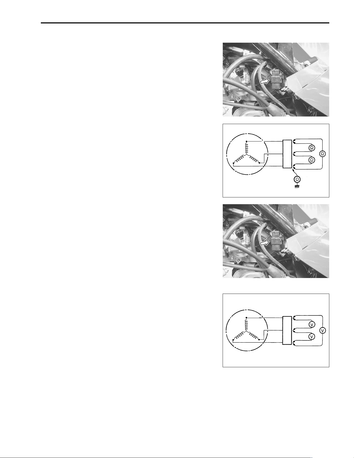
ELECTRICAL SYSTEM 8-9
GENERATOR COIL RESISTANCE
• Remove the fuel tank cover. (!7-5)
• Disconnect the generator coupler.
Measure the resistance between the three lead wires.
If the resistance is not specified value, replace the stator coil
with a new one.
Also, check that the generator core is insulated.
# 09900-25008: Multi circuit tester set
) Tester knob indication: Resistance (Ω
ΩΩ
Ω)
& Generator coil resistance: 0.1 – 1.5 Ω
ΩΩ
Ω (Black – Black)
∞ Ω
∞ Ω∞ Ω
∞ Ω (Black – Ground)
GENERATOR NO-LOAD PERFORMANCE
• Remove the fuel tank cover. (!7-5)
• Disconnect the generator lead wire coupler.
• Start the engine and run it at 5 000 r/min.
Measure the AC voltage between the lead wires of the generator
using the multi circuit tester.
If the voltage is under the specified value, replace the AC gener-
ator with a new one.
# 09900-25008: Multi circuit tester set
( Tester knob indication: Voltage (~)
& Generator no-load performance (when engine is cold):
More than 60 V (AC) at 5 000 r/min
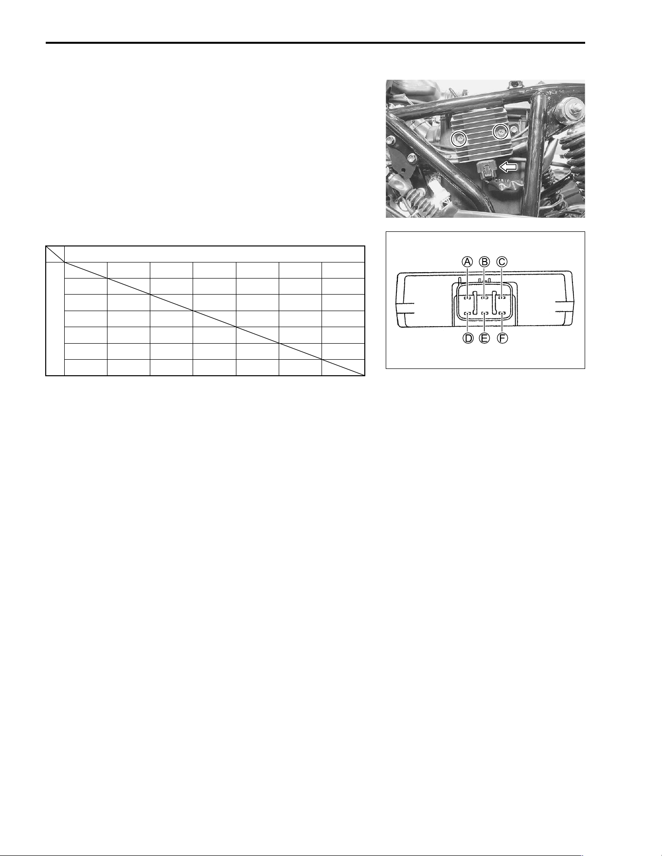
8-10 ELECTRICAL SYSTEM
REGULATOR/RECTIFIER
• Remove the rear fender. (!7-9)
• Remove the regulator/rectifier.
Measure the voltage between the terminals using the multi cir-
cuit tester, as indicated in the table below.
If the voltage is not within the specified value, replace the regu-
lator/rectifier with a new one.
# 09900-25008: Multi circuit tester set
* Tester knob indication: Diode test (+)
✽ More than 1.4 V (tester’s battery voltage)
NOTE:
If the tester reads under 1.4 V when the tester probes are not
connected, replace the battery of multi circuit tester.
Unit: V
+ Tester probe
- Tester probe
A
B
C
D
E
F
A ✽
0.4 – 0.7 0.3 – 0.6 0.3 – 0.6 0.3 – 0.6
B ✽✽✽✽✽
C ✽✽ ✽✽✽
D ✽✽
0.3 – 0.6
✽✽
E ✽✽
0.3 – 0.6
✽✽
F ✽✽
0.3 – 0.6
✽✽
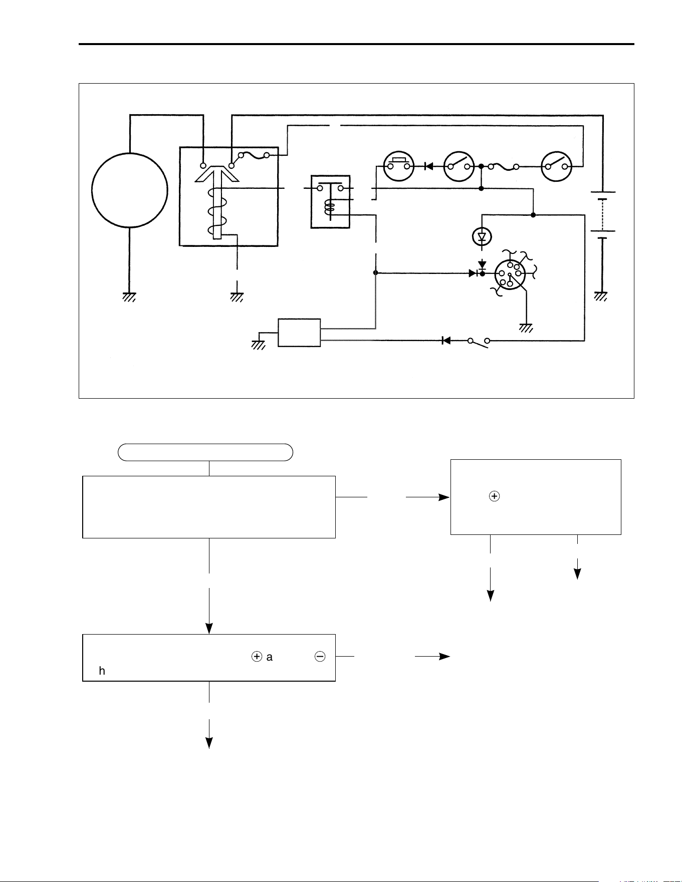
ELECTRICAL SYSTEM 8-11
STARTER SYSTEM
TROUBLESHOOTING
Starter
motor
Fuse
Starter relay
B/W
Y/B
R
Neutral relay
Starter
button
Engine
stop switch
Fuse
Ignition
switch
CDI
Parking
brake
switch
Neutral
indicator
light
O/Y
Y/G
Battery
Neutral
switch
N
Bl/B
B/Bl
Starter motor will not run.
The transfer is in neutral. Turn on the ignition
switch with the engine stop switch in the
“RUN” position. Listen for a click from the
starter relay when the starter button is pushed.
Check if the starter motor runs
when its terminal is connected
to the
+
battery terminal (Do
not use a thin wire because a
large amount of current flows.)
Measure the starter relay voltage at the starter
relay connectors (between Y/B
+
and B/W
-
)
when the starter button is pushed.
No click
Clicks
Runs
Voltage
No voltage
• Faulty starter relay
• Loose or disconnected starter
motor lead wire
• Faulty ignition switch
• Faulty engine stop switch
• Faulty neutral relay
• Faulty starter button
• Improper connector contact
• Open circuit in wire harness
Continued on next page
• Faulty starter motor
Does not run
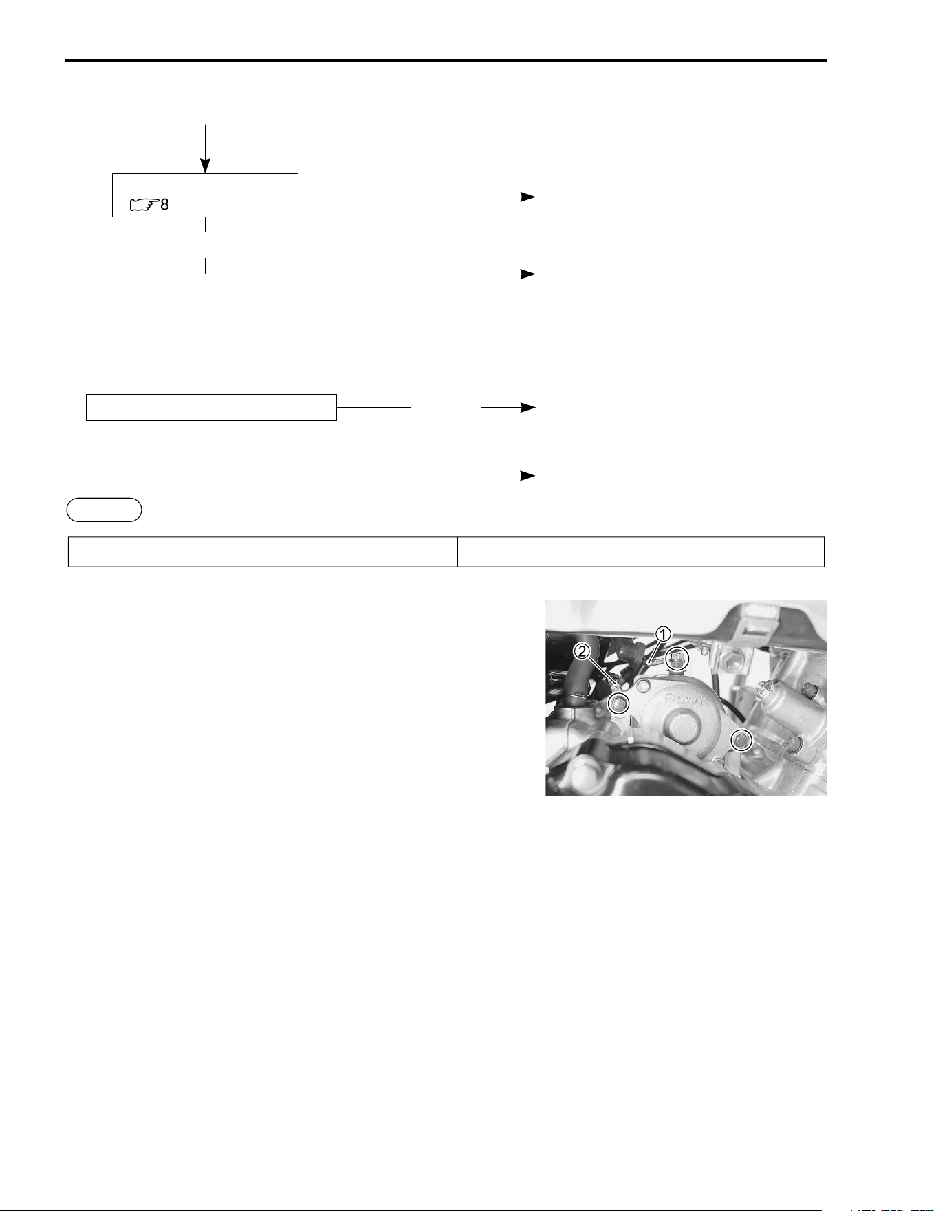
8-12 ELECTRICAL SYSTEM
STARTER MOTOR REMOVAL AND
DISASSEMBLY
• Remove the fuel tank cover. (!7-5)
• Remove the muffler cover. (!7-8)
• Disconnect the starter motor lead wire
1 and engine ground
lead wire
2.
• Remove the starter motor.
Incorrect
• Faulty starter relay
Correct
• Improper starter relay contact
Check the starter relay.
(
:
8-15)
Incorrect
The starter motor runs when the transfer gear position is in neutral, but does not run when the transfer
gear position is in any position other than neutral, with the parking brake lever grasp firmly.
• Open circuit in wire harness
• Poor contact of connector
Engine does not turn though the starter motor runs. • Faulty starter clutch
Check the parking brake switch.
Others
• Faulty parking brake switch
Correct
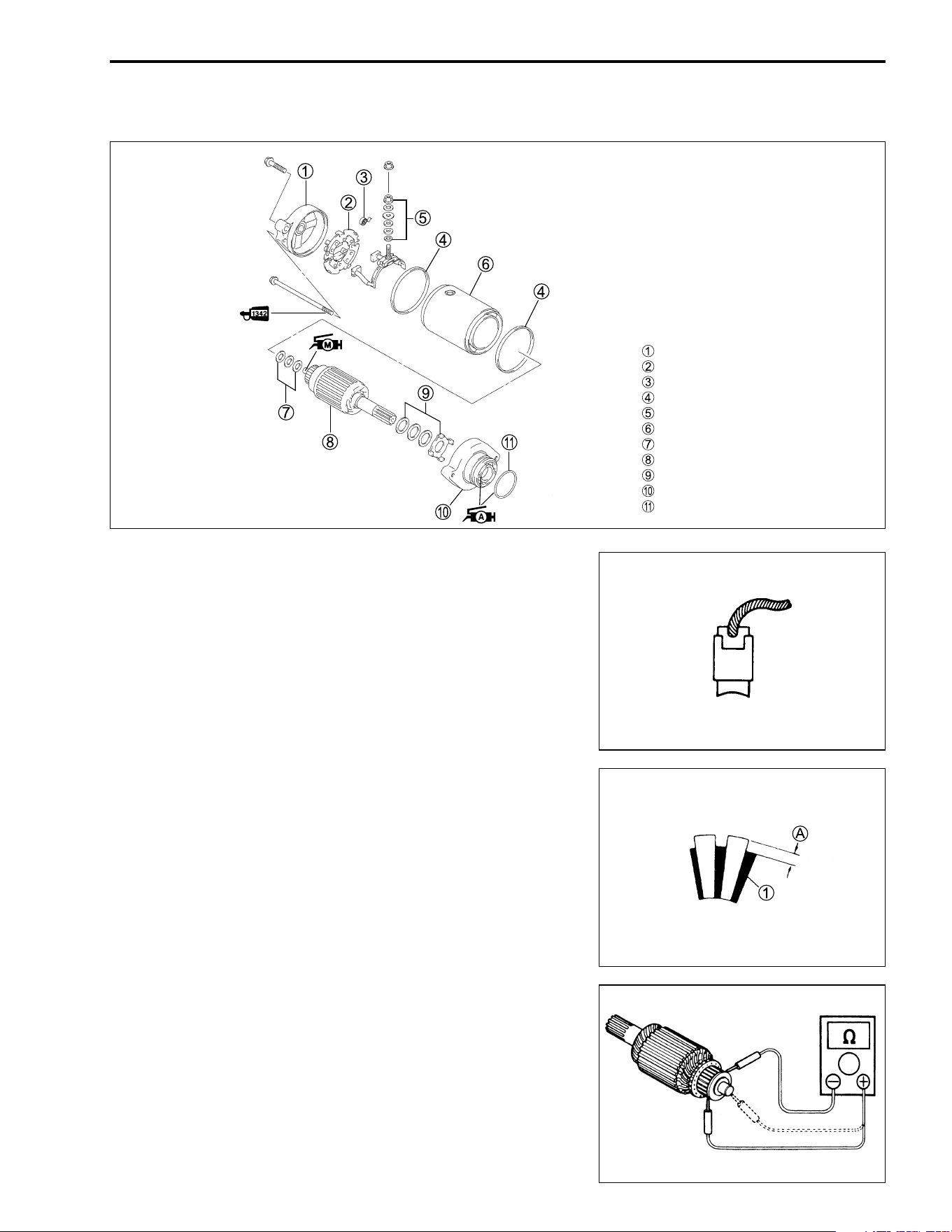
ELECTRICAL SYSTEM 8-13
• Disassembly the starter motor, as shown.
STARTER MOTOR INSPECTION
CARBON BRUSHES
Inspect the carbon brushes for abnormal wear, cracks, or
smoothness in the brush holder.
If any damages are found, replace the brush assembly with a
new one.
COMMUTATOR
Inspect the commutator for discoloration, abnormal wear or
undercut
A.
If abnormal wear is found, replace the armature with a new one.
If the commutator surface is discolored, polish it with #400 sand-
paper and wipe it using a clean, dry cloth.
If there is no undercut, scrape out the insulator
1 with a saw
blade.
ARMATURE COIL INSPECTION
Check for continuity between each segment and between each
segment and the armature shaft using the multi circuit tester.
If there is no continuity between the segments or there is conti-
nuity between the segments and shaft, replace the armature
with a new one.
# 09900-25008: Multi circuit tester set
, Tester knob indication: Continuity test (-)
Housing end (outside)
Brush holder
Brush spring
O-ring
Brush terminal set
Starter motor case
Washer set
Armature
Washer set
Housing end (inside)
O-ring
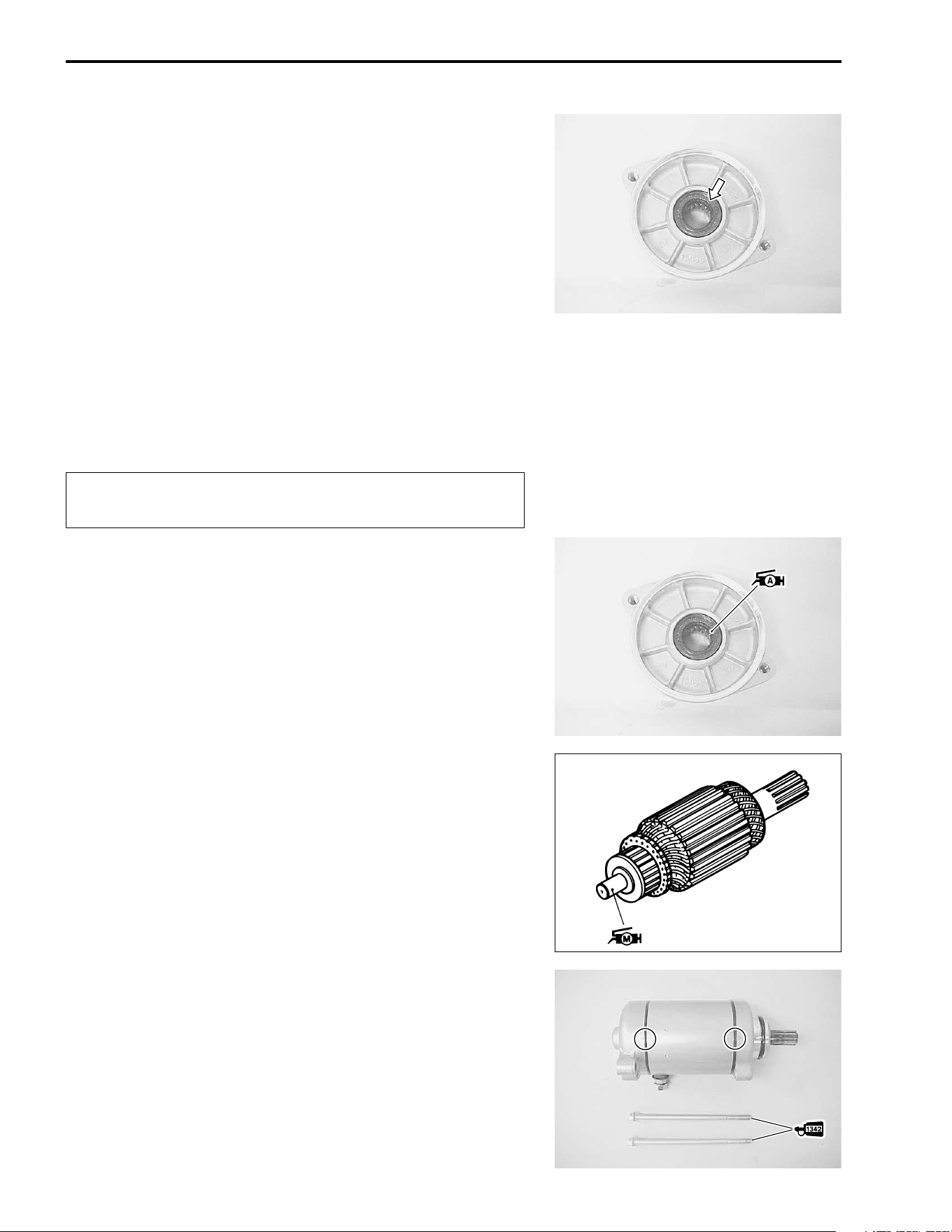
8-14 ELECTRICAL SYSTEM
OIL SEAL
Check the seal lip for damage or leakage. If any damages are
found, replace the starter motor with a new one.
STARTER MOTOR REASSEMBLY AND
REMOUNTING
Reassemble and remount the starter motor in the reverse order
of removal and disassembly. Pay attention to the following
points:
"
• Apply SUZUKI SUPER GREASE “A” to the lip of the oil seal.
. 99000-25030: SUZUKI SUPER GREASE “A” (USA)
99000-25010: SUZUKI SUPER GREASE “A” (Others)
• Apply a small quantity of SUZUKI MOLY PASTE to the arma-
ture shaft.
/ 99000-25140: SUZUKI MOLY PASTE
• Align the match marks on the starter motor case with the
match mark on the housing end.
• Apply a small quantity of THREAD LOCK “1342” to the starter
motor housing bolts and tighten it sequrely.
0 99000-32050: THREAD LOCK “1342”
Replace the removed O-rings with new ones to pre-
vent oil leakage and moisture.
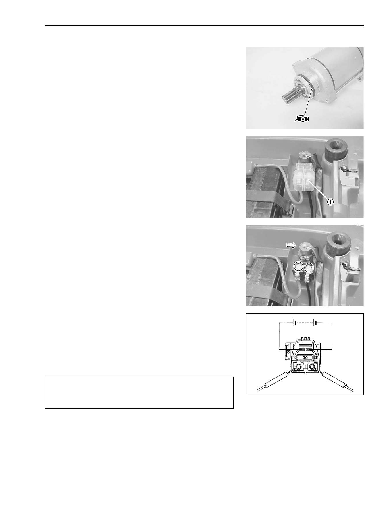
ELECTRICAL SYSTEM 8-15
• Apply SUZUKI SUPER GREASE “A” to the O-ring .
. 99000-25030: SUZUKI SUPER GREASE “A” (USA)
99000-25010: SUZUKI SUPER GREASE “A” (Others)
• Connect the starter lead wire and the engine ground lead
wire. (!9-14)
STARTER RELAY INSPECTION
• Remove the seat. (!7-4)
• Disconnect the battery
- lead wire at battery terminal.
• Remove the starter relay cover
1.
• Disconnect the starter motor lead wire, battery lead wire and
starter relay coupler at the starter relay.
• Remove the starter relay.
Apply 12 V to the terminals and check for continuity between the
positive and negative terminals using the multi circuit tester. If
the starter relay clicks and continuity is found, the relay is ok.
# 09900-25008: Multi circuit tester set
, Tester knob indication: Continuity test (-)
"
Do not apply a battery voltage to the starter relay for
more than five seconds.
This may overheat and damage the relay coil.
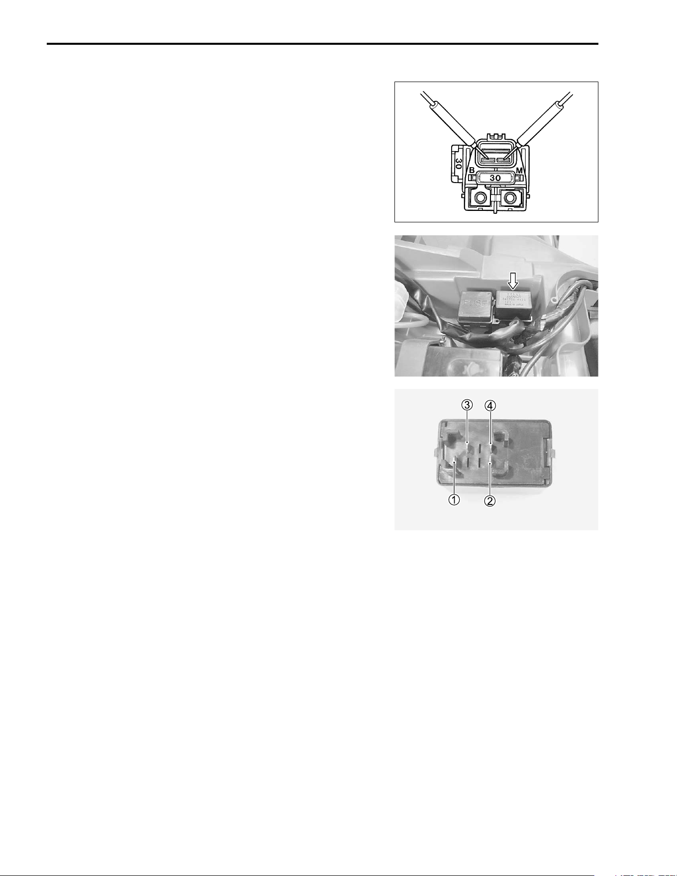
8-16 ELECTRICAL SYSTEM
Measure the relay coil resistance between the terminals using
the multi circuit tester. If the resistance is not within the specified
value, replace the starter relay with a new one.
# 09900-25008: Multi circuit tester set
) Tester knob indication: Resistance (Ω
ΩΩ
Ω)
& Starter relay resistance
Standard: 3 – 5 Ω
ΩΩ
Ω
NEUTRAL RELAY INSPECTION
• Remove the seat. (! 7-4)
• Disconnect the neutral relay.
Apply 12 V to terminals
1 and
2 (
+ to
1 and
- to
2) and
check the continuity between
3 and
4 using a multi circuit
tester. If there is no continuity found, replace the neutral relay
with a new one.
# 09900-25008: Multi circuit tester set
, Tester knob indication: Continuity set (-)
PARKING BRAKE SWITCH
(!8-33)
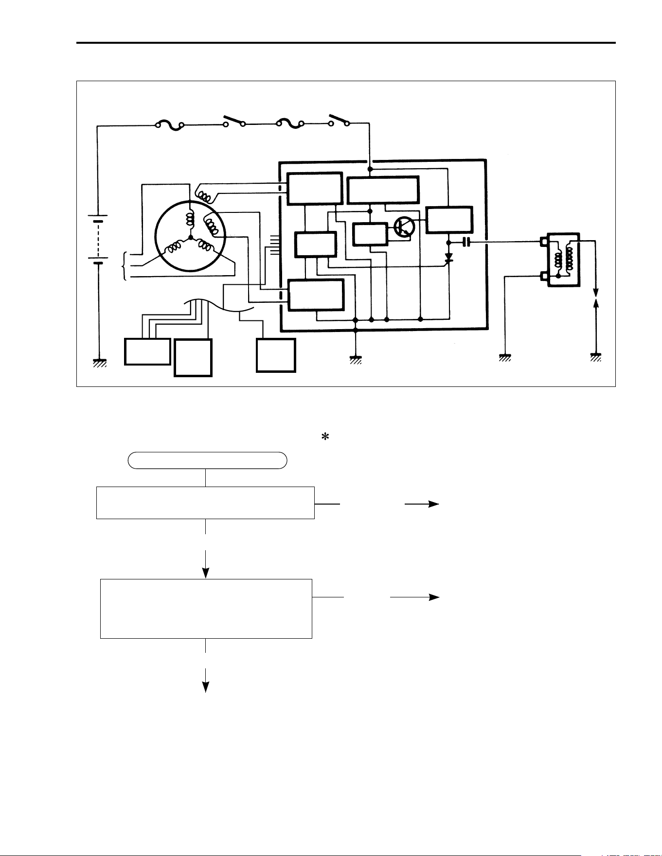
ELECTRICAL SYSTEM 8-17
IGNITION SYSTEM
TROUBLESHOOTING
Spark plug
Ignition
coil
DC-DC
converter
Ignition power
source circuit
Wave form
arrangment
circuit
CPU
Driver
SCR
C
CDI unit
Wave form
arrangment
circuit
Engine
stop switch
Fuse
Ignition
switch
Fuse
Battery
Generator
Bl
G
Y
W
Transfer
switch
Parking
brake
switch
Neutral/
parking
switch
Correct
Continued on next page
• Improper coupler connection
• Faulty ignition switch
• Faulty engine stop switch
• Broken wire harness or poor
connection of related circuit
couplers
No spark or poor spark
Check ignition system couplers for poor
connections.
Measure the battery voltage between
input lead wires (O/W and B/W) at the
CDI unit with the ignition switch in the
“ON” position.
Inorrect
Looseness
Make sure the transfer is in the neutral position
and the engine stop switch is in the “RUN” position.
Also, make sure the fuse is not blown and the
battery is fully-charged before diagnosing.
Correct
8-18 ELECTRICAL SYSTEM
Measure the ignition coil primary peak
voltage. (
:
8-19)
NOTE: The ignition coil peak voltage
inspection method is applicable only with the
multi circuit tester and the peak volt adaptor.
Inspect the ignition coil. (
:
8-20)
Measure the pickup coil and power source
coil resistance. (
:
8-20)
Inspect the spark plug.
(
:
2-7)
• Faulty spark plug
• Improper spark plug
connection
• Faulty pickup coil
• Faulty power source coil
• Faulty ignition coil
• Faulty CDI unit
• Open circuit in wiring
harness
• Improper ignition coupler
connection
Correct
Correct
Incorrect
Incorrect
Incorrect
Correct
Incorrect
Correct
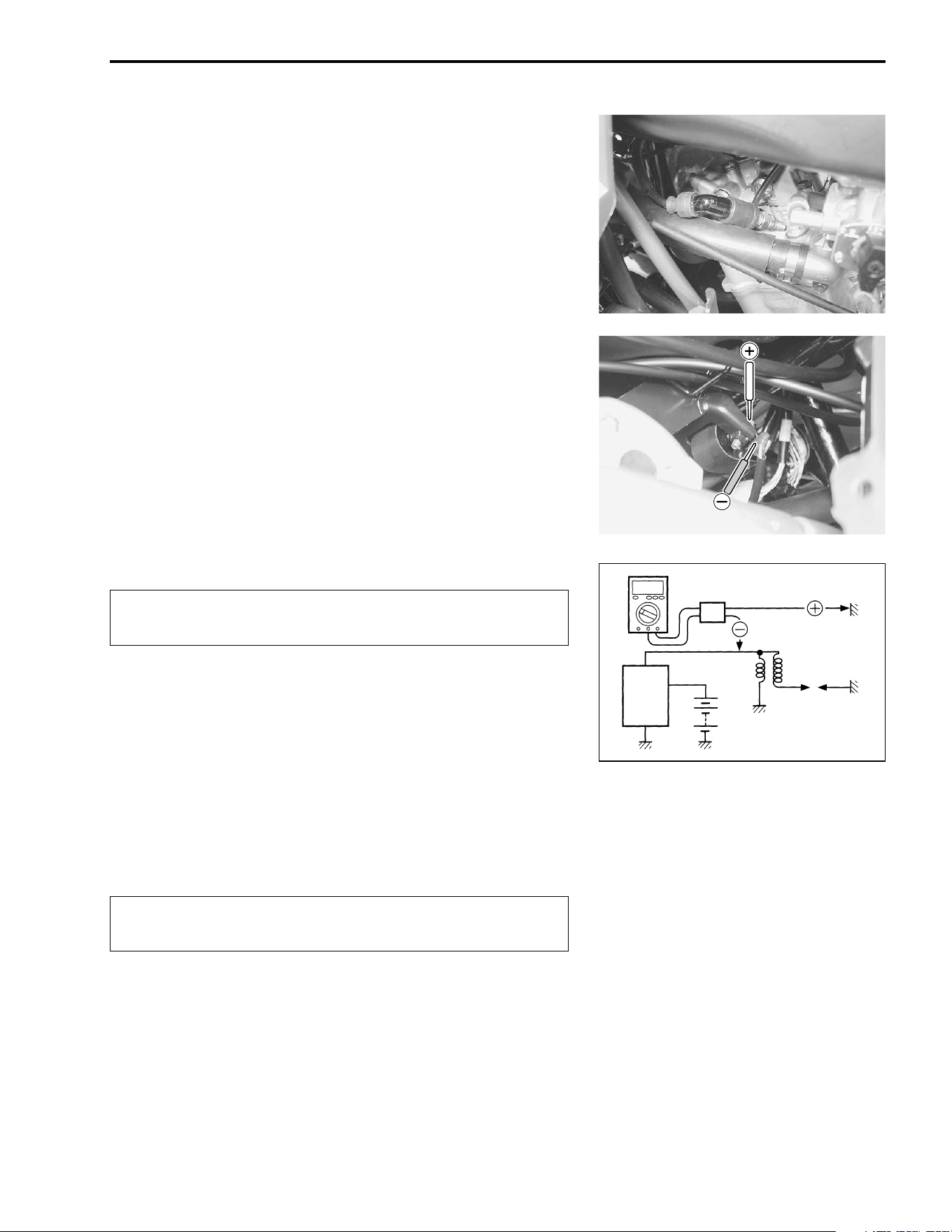
ELECTRICAL SYSTEM 8-19
INSPECTION
IGNITION COIL PRIMARY PEAK VOLTAGE
• Remove the fuel tank cover. (!7-5)
• Remove the spark plug cap.
• Connect a new spark plug to spark plug cap and ground it to
the cylinder head.
NOTE:
Make sure that the spark plug cap and spark plug are connected
properly and the battery is fully-charged.
Measure ignition coil primary peak voltage using the multi circuit
tester in the following procedure.
• Connect the multi circuit tester with the peak voltage adaptor
as follows.
+ Probe: Black/White lead wire or Ground
- Probe: White/Blue lead wire
NOTE:
Do not disconnect the ignition coil primary wire.
# 09900-25008: Multi circuit tester set
"
• Shift the transfer to the neutral position and turn the ignition
switch to the “ON” position.
• Press the starter button and allow the engine to crank for a
few seconds, and then measure the ignition coil primary peak
voltage.
• Repeat the above procedure a few times and measure the
highest ignition coil primary peak voltage.
( Tester knob indication: Voltage (%)
& Ignition coil primary peak voltage: More than 150 V
1
If the voltage is lower than the standard values, inspect the igni-
tion coil. (!8-20)
When using the multi circuit tester and peak volt adap-
tor, refer to the appropriate instruction manual.
While testing, do not touch the tester probes and
spark plug to prevent receiving an electric shock.
Peak volt adaptor
CDI
unit
Battery
New spark plug
Ignition
coil
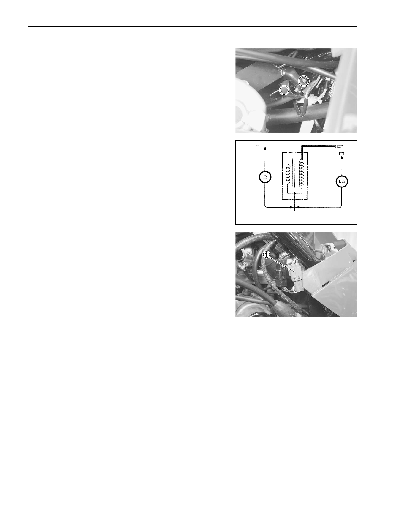
8-20 ELECTRICAL SYSTEM
IGNITION COIL RESISTANCE
• Remove the fuel tank cover. (!7-5)
• Disconnect the ignition coil lead wire and spark plug cap, and
remove the ignition oil.
Measure the ignition coil resistance in both the primary and sec-
ondary windings using the multi circuit tester. If the resistance in
both the primary and secondary windings is close to the speci-
fied values, the windings are in sound condition.
# 09900-25008: Multi circuit tester set
) Tester knob indication: Resistance (Ω
ΩΩ
Ω)
& Ignition coil resistance
Primary : 0.1 – 1.5 Ω
ΩΩ
Ω (Terminal – Ground)
Secondary : 12 – 22 kΩ
ΩΩ
Ω (Spark plug cap – Terminal)
PICKUP COIL AND POWER SOURCE COIL RESISTANCE
• Remove the fuel tank cover. (!7-5)
• Disconnect the generator coupler
1.
Measure the resistance between the lead wires using the multi
circuit tester. If the resistance is not within the spcified value,
stator coil must be replaced.
# 09900-25008: Multi circuit tester set
) Tester knob indication: Resistance (Ω
ΩΩ
Ω)
& Pickup coil resistance: 150 – 300 Ω
ΩΩ
Ω (Blue – Green)
Power source coil resistance:
0.05 – 1.0 Ω
ΩΩ
Ω (Yellow – White)
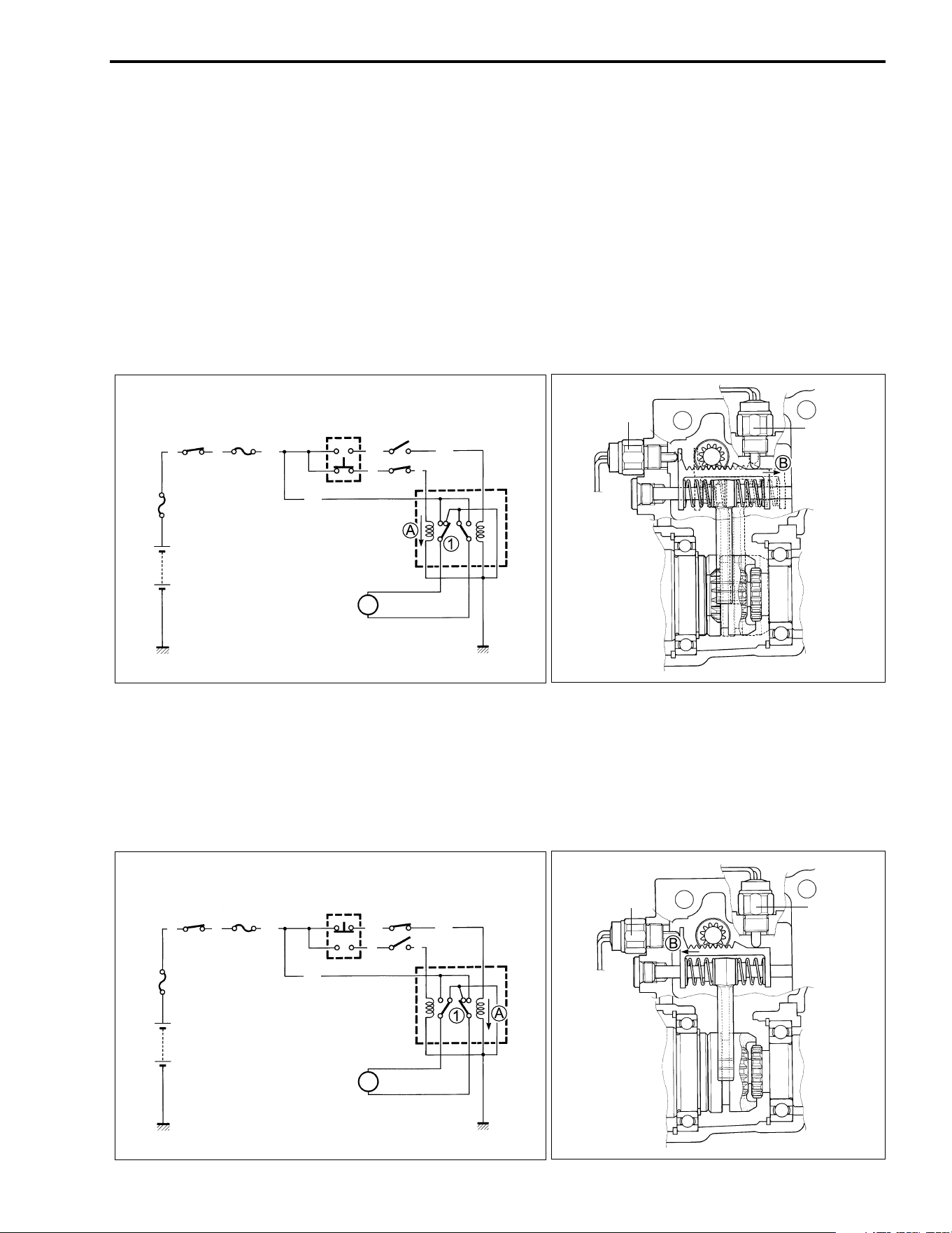
ELECTRICAL SYSTEM 8-21
2WD/4WD SELECTING SYSTEM
DESCRIPTION
The 2WD/4WD selecting system consists of the following components: the 2WD/4WD selecting button,
2WD switch, 4WD switch, 2WD/4WD selecting relay, 2WD/4WD motor and battery.
TO SHIFT FROM 2-WHEEL DRIVE TO 4-WHEEL DRIVE:
Depress the 2WD/4WD selecting button with the ignition switch in ON position.
Depressing this switch causes current
A to flow as shown, energizing the 2WD/4WD selecting relay coil.
The coil pulls and closes the contact point
1 allowing current to flow to the motor. Then, the motor starts to
operate and moves the rack in the direction
B together with the shift fork and sliding dog. As a result, the
driving mode is changed from 2-wheel drive to 4-wheel drive. Also operated at this time are the 4WD switch
and 2WD switch. The 4WD switch turns OFF from ON while the 2WD switch turns ON from OFF. Therefore,
current
A is interrupted and the contact point
1 returns to OFF state. Now the motor stops operating.
TO SHIFT FROM 4-WHEEL DRIVE TO 2-WHEEL DRIVE:
Depress the 2WD/4WD selecting button.
Current
A flows and the contact point
1 closes, causing the motor to turn reversely as opposite to the
phase of 2WD→4WD. The rack as shown moves in the direction
B, causing the driving mode to change
from 4-wheel drive to 2-wheel drive. This time, the 2WD switch operates as ON→OFF and 4WD switch as
OFF→ON. Then, current
A no longer flows allowing the contact point
1 to return to OFF. Now the motor
stops.
2WD
switch
4WD
switch
2WD/4WD
motor
M
2WD/4WD
selecting
relay
2WD switch
2WD/4WD
selecting
button
Fuse
Ignition
switch
Main
fuse
Battery
4WD
switch
O/Y
O/Y
O
R
B
B/R
B/R
Bl
2WD
switch
4WD
switch
2WD/4WD
motor
M
2WD/4WD
selecting
relay
2WD switch
2WD/4WD
selecting
button
Fuse
Ignition
switch
Main
fuse
Battery
4WD
switch
O/Y
O/Y
O
R
B
B/R
B/R
Bl
8-22 ELECTRICAL SYSTEM
TROUBLESHOOTING
Does not shift to 2WD/4WD
(2WD/4WD motor will not run.)
Check the 2WD/4WD motor.
(
:
8-23)
Clicks
Runs
• Faulty 2WD/4WD selecting relay
• Improper 2WD/4WD motor
coupler connection
• Faulty 2WD/4WD motor
Does not run
• Faulty 2WD/4WD selecting button
Correct
• Open circuit in wire harness
Incorrect
• Faulty 2WD/4WD selecting relay
Incorrect
Check the 2WD/4WD selecting button.
(
:
8-33)
Check the 2WD/4WD selecting relay.
(
:
8-23 to 8-24)
Check the 2WD switch or 4WD switch
(
:
8-24)
• Faulty 2WD switch or 4WD switch
Incorrect
Correct
Correct
The 2WD/4WD motor runs, but does not shift to 2WD/4WD.
Check the front differential sliding dog. (
:
4-7)
Turn on the ignition switch. Listen for a click
from the 2WD/4WD selecting relay when the
2WD/4WD selecting button is pushed.
No click
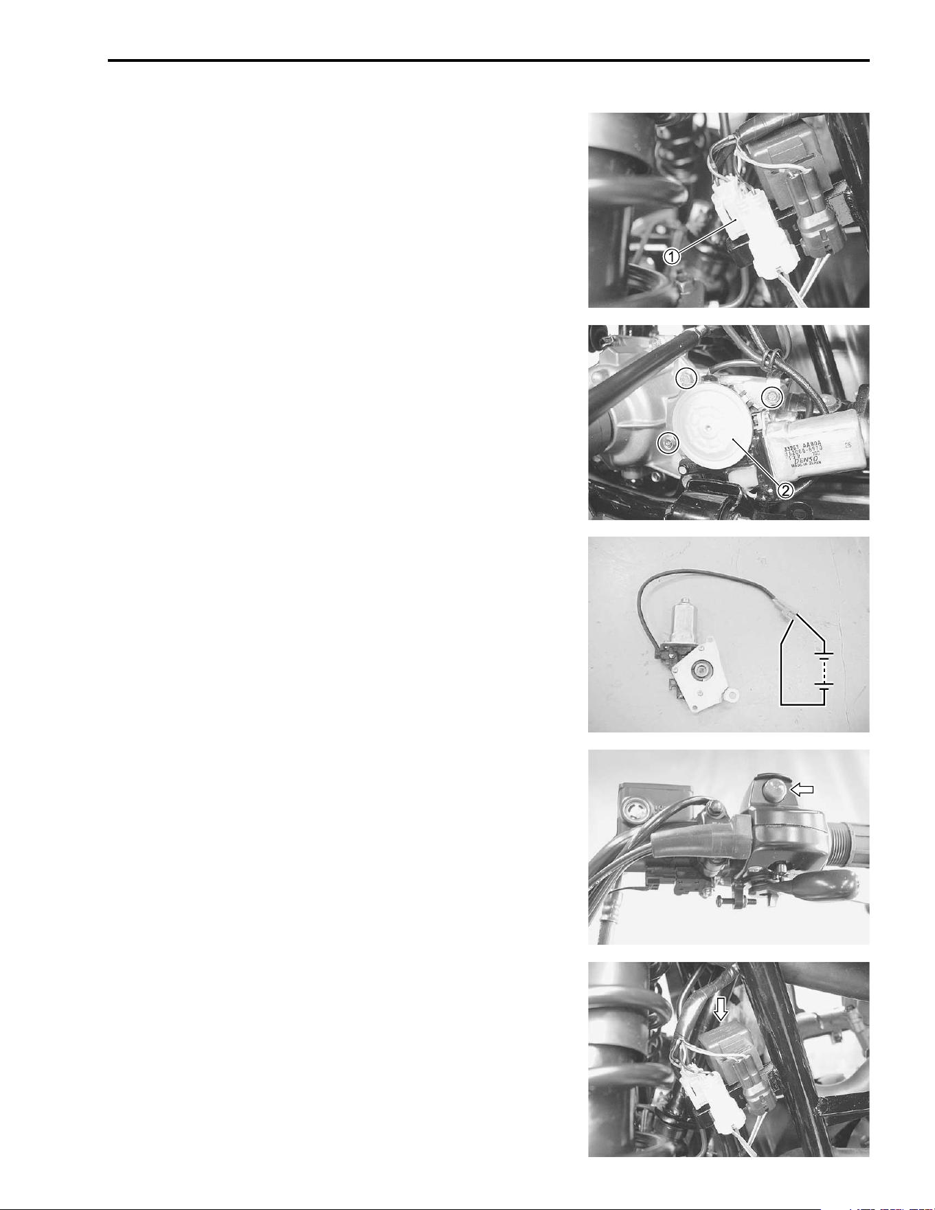
ELECTRICAL SYSTEM 8-23
INSPECTION
2WD/4WD MOTOR
• Remove the left inner fender. (!7-7)
• Disconnect the 2WD/4WD motor coupler
1.
• Remove the 2WD/4WD motor
2.
Connect the 12 V battery to the 2WD/4WD motor lead wires as
shown. If the motor does not run, replace the motor assembly
with a new one.
• Install the 2WD/4WD motor and tighten the bolts to the speci-
fied torque. (!4-15)
2WD/4WD SELECTING BUTTON
(!8-33)
2WD/4WD SELECTING RELAY
• Remove the left inner fender. (!7-7)
• Remove the 2WD/4WD selecting relay.
12 V12 V
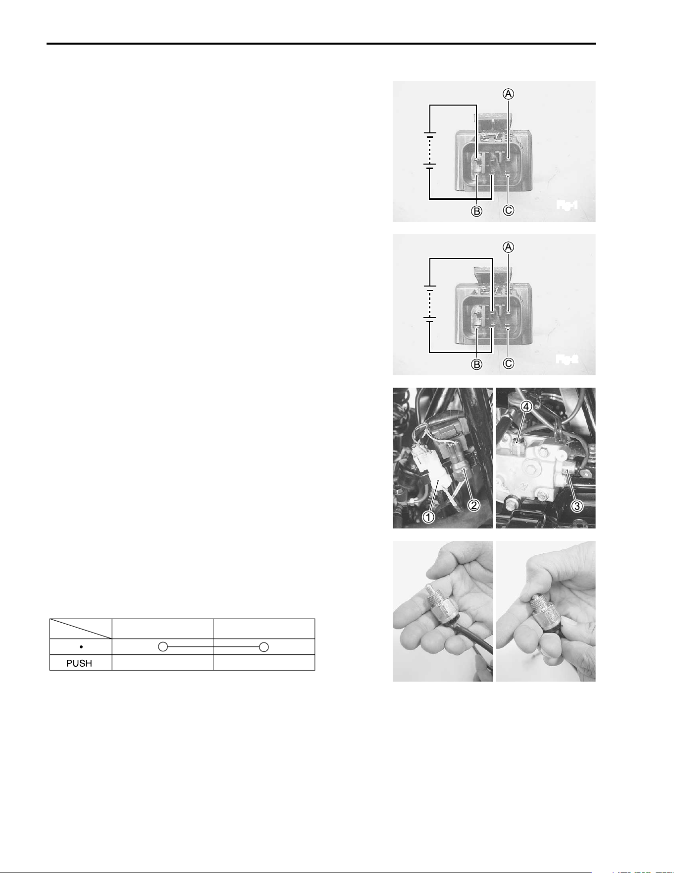
8-24 ELECTRICAL SYSTEM
First check the insulation between
B and
C and between
A
and
C terminals with the tester.
Apply 12 V to the terminals as shown in Fig-1, and check the
continuity between
B and
C.
Apply 12 V to the terminals as shown in Fig-2, and check the
continuity between
A and
C.
If there is no continuity, replace the 2WD/4WD selecting relay
with a new one.
2WD SWITCH AND 4WD SWITCH
• Remove the 2WD/4WD motor. (!8-23)
• Disconnect the switch couplers (
1,
2).
• Remove the 2WD switch
3 and 4WD switch
4.
Measure 2WD switch and 4WD switch for continuity using a
multi circuit tester. If there is no continuity, replace the 2WD
switch and 4WD switch with a new one.
# 09900-25008: Multi circuit tester set
• Install the 2WD switch and 4WD switch. (!4-15)
Fig-1
Fig-2
Color
Position
R/W
R/W
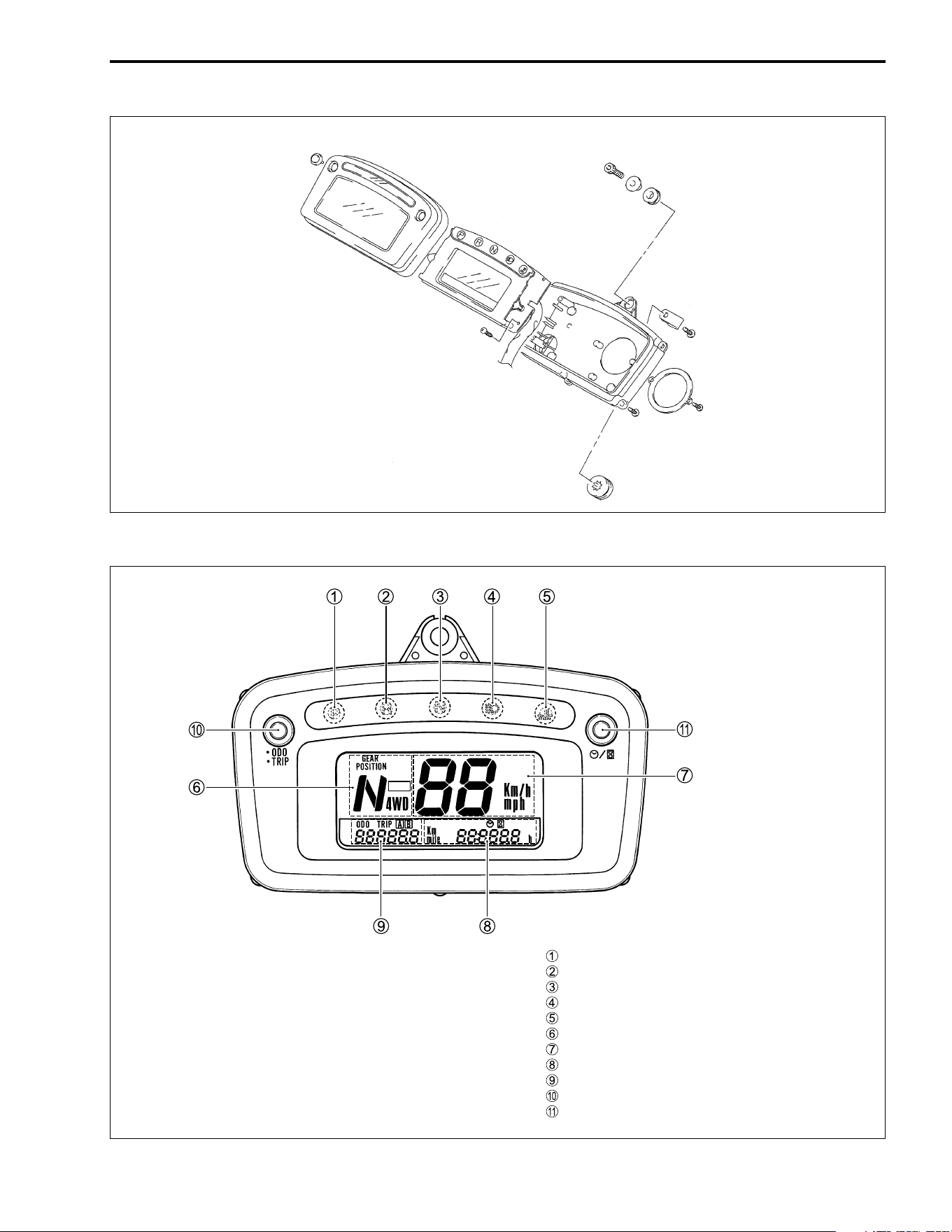
ELECTRICAL SYSTEM 8-25
SPEEDOMETER
PARTS NAMES
Parking indicator light
Reverse indicator light
Neutral indicator light
High beam indicator light
Engine coolant temperature indicator light
Gear position
Speedometer
Clock/hour
Odometer/tripmeter (A, B)
ODO/TRIP button
Clock/Hour button
LOW
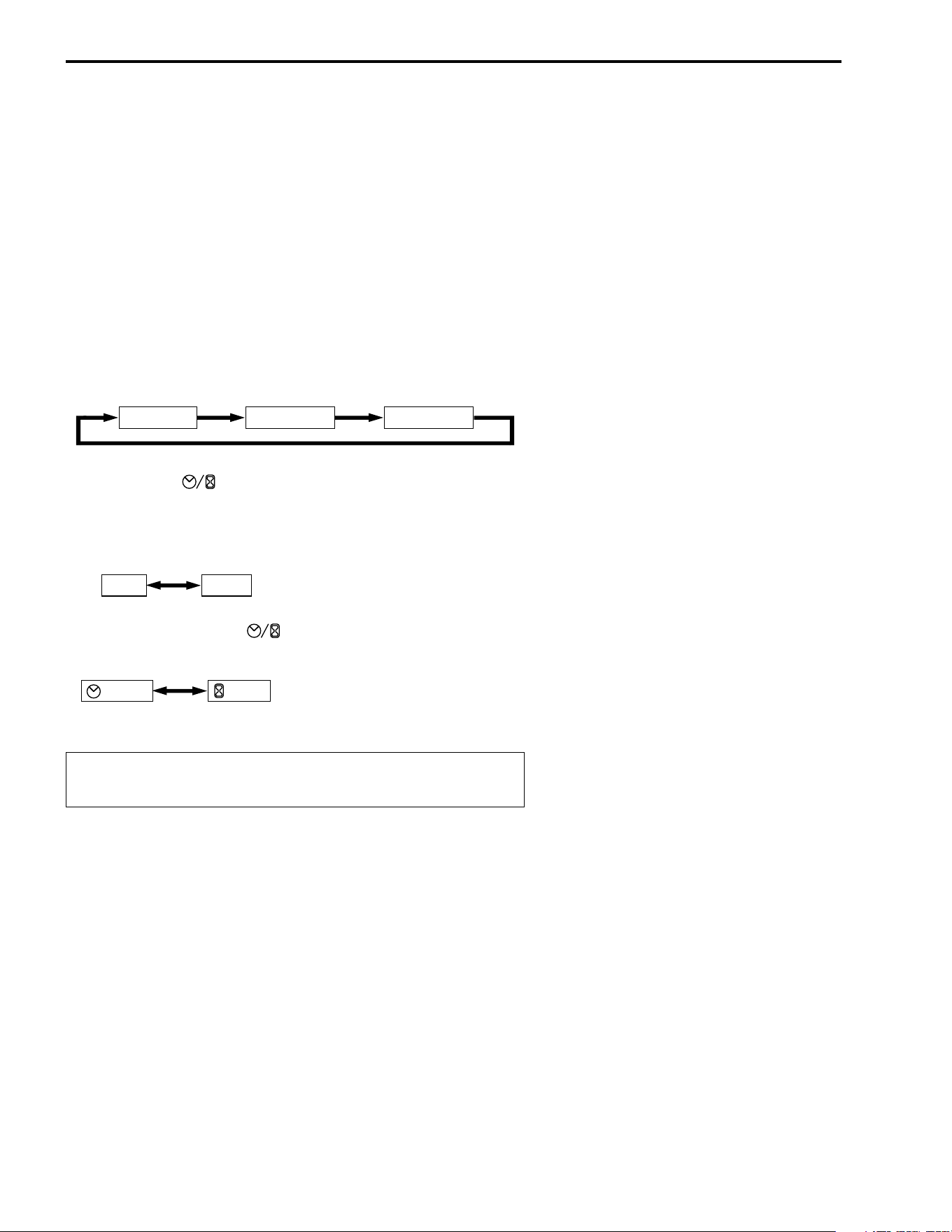
8-26 ELECTRICAL SYSTEM
OPERATING PROCEDURE
INITIAL DISPLAY
When the ignition switch is set to ON, all LCD and engine cool-
ant temperature indicator light light up for two seconds.
NOTE:
If the power supply is cut (e.g., when the battery is replaced);
* The odometer, tripmeter and clock are displayed after the ini-
tial display appears.
* Since the clock resets to “1:00”, it will need to be readjusted.
CHANGE THE DISPLAY MODE
With each press of the ODO/TRIP button, the display changes
between odometer, tripmeter A and tripmeter B as shown.
Hold down the (CLOCK/HOUR) button over two seconds
while pressing the ODO/TRIP button, the display changes
between “mph” and “km/h”, when displaying odometer as
shown.
With each press of the (CLOCK/HOUR) button, the dis-
play changes between clock and hour as shown.
1
ODOMETER
Displays the total distance travelled.
TRIPMETER
Displays the distance travelled since the tripmeter was last
reset.
NOTE:
The tripmeters “A” and “B” can be used independently.
Hold down the ODO/TRIP button over two seconds to reset the
tripmeter.
Odometer Tripmeter A Tripmeter B
mph km/h
Clock Hour
To aboid riding with only one hand, do not operate the
buttons while riding.
ELECTRICAL SYSTEM 8-27
CLOCK
Displays the time (hour and minutes) on a 12-hour clock.
Setting the time
Hold down the button over two seconds and then flashing
the minute display.
2 Select the correct minutes by
pressing the button.
Decide the minutes by pressing the ODO/TRIP button, and then
flashing the hour display.
2 Select the correct hour by press-
ing the button.
Decide the hours by pressing the ODO/TRIP button.
GEAR POSITION INDICATOR
Gear Position Indicator
The gear position indicator indicates shift lever positions: P, R,
N, 1, 2, 3, 4, 5.
P: Shift lever is in parking position. The parking indicator also
comes on.
R: Shift lever is in reverse position. The reverse indicator also
comes on.
N: Shift lever is in neutral position. The neutral indicator also
comes on.
1 to 5: Numeral indicates gear position.
Transfer Position Indicator
LOW: Shift lever is in low position.
NOTE:
* In conbination other than the above, brinking of error display “–” shall be performed.
* When shift lever is the position of parking, not neutral position and reverse position, parking indicator light
would be blinking.
min.
hour
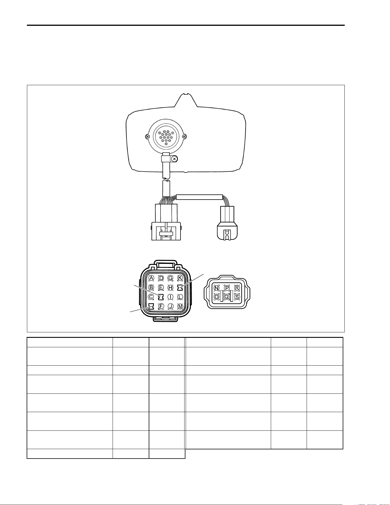
8-28 ELECTRICAL SYSTEM
INSPECTION
SPEEDOMETER
• Remove the speedometer assembly. (! 7-42)
• Apply 12 V to the terminals and check that the indicators are turned on.
If the speedometer, odometer or trip meter does not function properly. Inspect the speed sensor and con-
nection of couplers. If the speed sensor and connection is all right, replace the speedometer with a new one.
ITEM Battery
+ Battery
- ITEM Battery
+ Battery
-
LCD (Gear position, 4WD,
Speed, Odometer, Clock)
A &
D
M 3: 3rd gear position (LCD)
A &
D
M &
Q
Meter illumination
J
M 4: 4th gear position (LCD)
A &
D
M &
S
P: Parking
(LCD and indicator light)
A &
D &
I
M &
P 5: 5th gear position (LCD)
A &
D
M &
R
N: Neutral
(LCD and indicator light)
A &
D
M &
P High beam indicator light
C
M
R: Reverse
(LCD and indicator light)
A &
D
L &
M
Engine coolant temperature
indicator light
D
F
1: 1st gear position (LCD)
A &
D
M &
N
LOW: Transfer indicator
(LCD)
A &
D
M &
B
2: 2nd gear position (LCD)
A &
D
M &
O
NIL
NIL
NIL
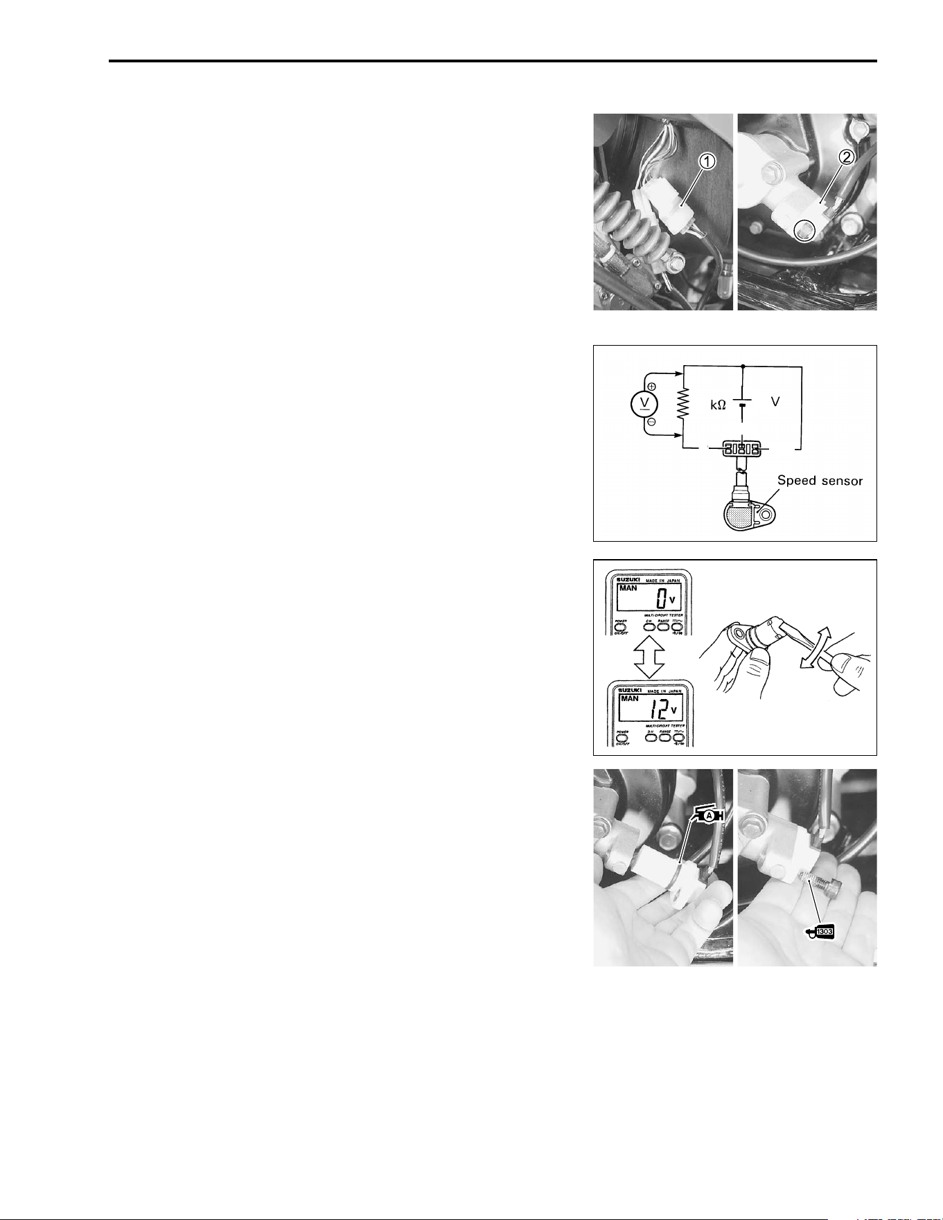
ELECTRICAL SYSTEM 8-29
SPEED SENSOR
• Remove the left footrest mud guard. (!7-8)
• Disconnect the speed sensor lead wire coupler
1.
• Remove the speed sensor
2.
• Connect
- terminal to ground terminal and
+ to the Vcc ter-
minal.
• Connect 1 kΩ resistor, 12 V battery and the multi circuit tester
as shown.
# 09900-25008: Multi circuit tester set
( Tester knob indication: Voltage (%
%%
%)
Under above condition, when a suitable screwdriver touching
the pick-up surface of the speed sensor moves, the tester read-
ing voltage relatively changes (0 V → 12 V or 12 V → 0 V). If the
tester reading voltage does not change, replace the speed sen-
sor with a new one.
NOTE:
The highest tester reading voltage (12 V) while testing is same
as the total voltage of four batteries.
• Apply SUZUKI SUPER GREASE “A” to the speed sensor O-
ring before installing it.
. 99000-25030: SUZUKI SUPER GREASE “A” (USA)
99000-25010: SUZUKI SUPER GREASE “A” (Others)
• Apply THREAD LOCK SUPER “1303” to the speed sensor
mounting bolt
3.
• Tighten the speed sensor mounting bolt to the specified
torque.
3 99000-32030: THREAD LOCK SUPER “1303”
4 Speed sensor mounting bolt: 10 N·m (1.0 kgf-m, 7.0 lb-ft)
1
12
R/B
P
B/W
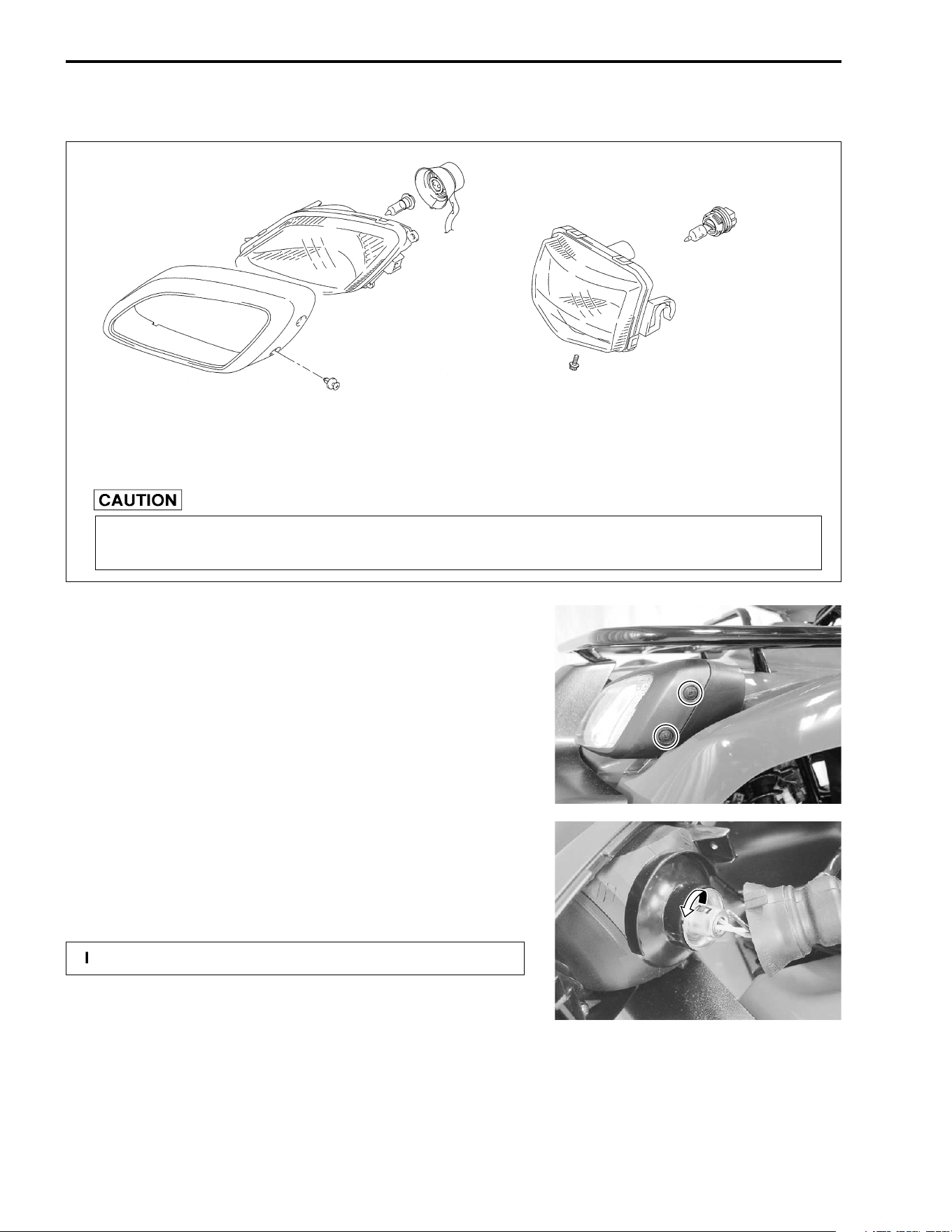
8-30 ELECTRICAL SYSTEM
LAMPS
HEADLIGHT AND AUXILIARY LIGHT
HEADLIGHT BULB REPLACEMENT
• Remove the headlight.
• Remove the rubber cap.
• Remove the socket.
• Remove the bulb.
• Install the new bulb in the reverse order of removal.
"
Headlight bulb: 12 V 30/30 W
(Right & Left)
Auxiliary light: 12 V 40 W
If you touch the bulb with your bare hands, clean the bulb with a cloth moistened with
alcohol or soapy water to prevent premature bulb failure.
!
Install the socket cover correctly.
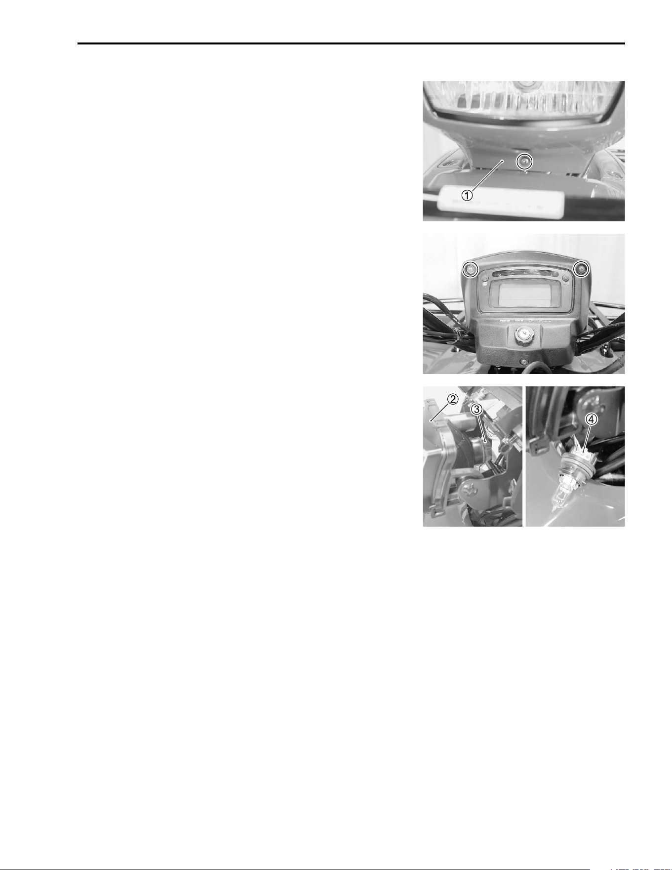
ELECTRICAL SYSTEM 8-31
AUXILIARY LIGHT BULB REPLACEMENT
• Remove the auxiliary light cover
1.
• Remove the auxiliary light
2.
• Remove the socket
3 with lead wire.
• Disconnect the lead wire coupler
4.
• Install the new bulb assembly in the reverse order of removal.
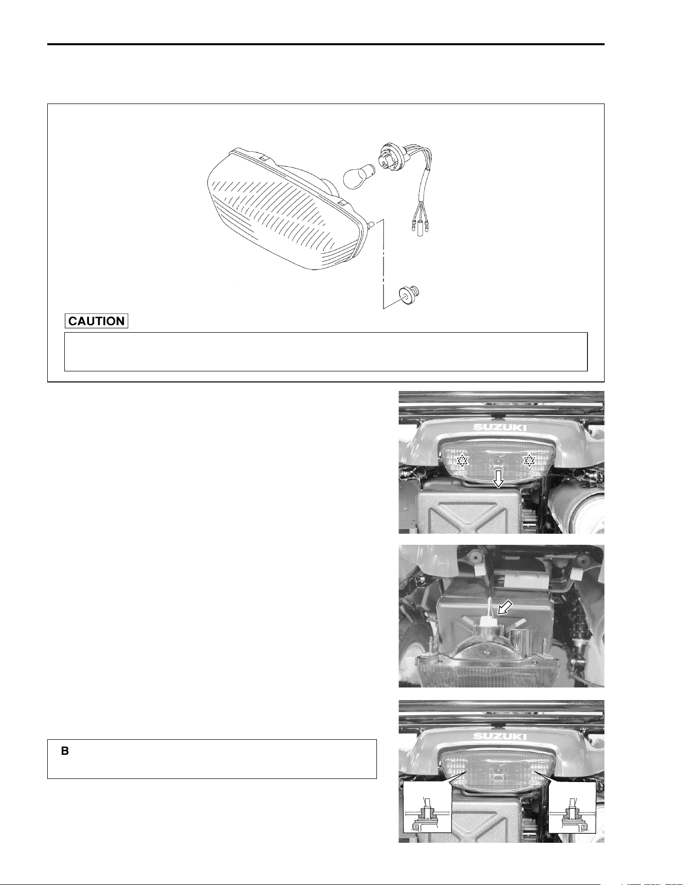
8-32 ELECTRICAL SYSTEM
BRAKE LIGHT/TAILLIGHT
BULB REPLACEMENT
• Remove the brake light/taillight assembly backward.
✡
Boss of connector
• Remove the socket.
• Remove the bulb.
• Install the new bulb in the reverse order of removal.
• Install the brake light/taillight assembly.
"
Brake light/taillight: 12 V 21/5 W
If you touch the bulb with your bare hands, clean the bulb with a cloth moistened with
alcohol or soapy water to prevent premature bulb failure.
!
Be sure to fix the boss of connector correctly as
shown.
Boss of
connector
Boss of
connector
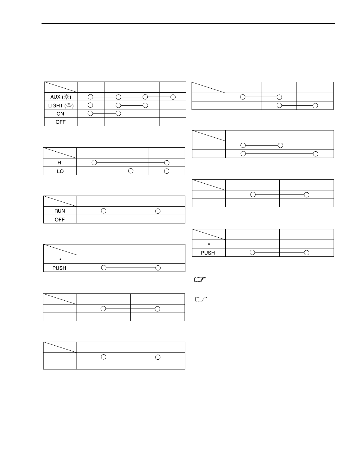
ELECTRICAL SYSTEM 8-33
SWITCHES
Measure each switch for continuity using a multi circuit tester. If any abnormality is found, replace the
respective switch assemblies with a new one.
# 09900-25008: Multi circuit tester set
IGNITION SWITCH
DIMMER SWITCH
ENGINE STOP SWITCH
STARTER BUTTON
REAR BRAKE PEDAL SWITCH
FRONT BRAKE SWITCH
PARKING POSITION SWITCH
2WD/4WD SELECTING BUTTON
PARKING BRAKE SWITCH
HORN BUTTON (For E-24)
COOLING FAN THERMO SWITCH
ENGINE COOLANT TEMPERATURE SWITCH
Color
Position
R
OGr P
Color
Position
Y
WGr
Color
Position
O
O/W
Color
Position
O/W
Y/G
Color
Position
O
W/B
ON
OFF
Color
Position
Terminal
Terminal
ON
OFF
OFF
ON
Color
Position
Bl
OY
2WD
4WD
Color
Position
O
BBl
Color
Position
W
Bl
ON
OFF
Color
Position
G
B/W
WIRE COLOR
B : Black
Bl : Blue
G : Green
Gr : Gray
O : Orange
P : Pink
R : Red
W : White
Y : Yellow
B/W : Black with White tracer
Br/R : Brown with Red tracer
G/Bl : Green with Blue tracer
G/R : Green with Red tracer
O/W : Orange with White tracer
R/W : Red with White tracer
W/B : White with Black tracer
W/Y : White with Yellow tracer
Y/Bl : Yellow with Blue tracer
Y/G : Yellow with Green tracer
6-9
6-10
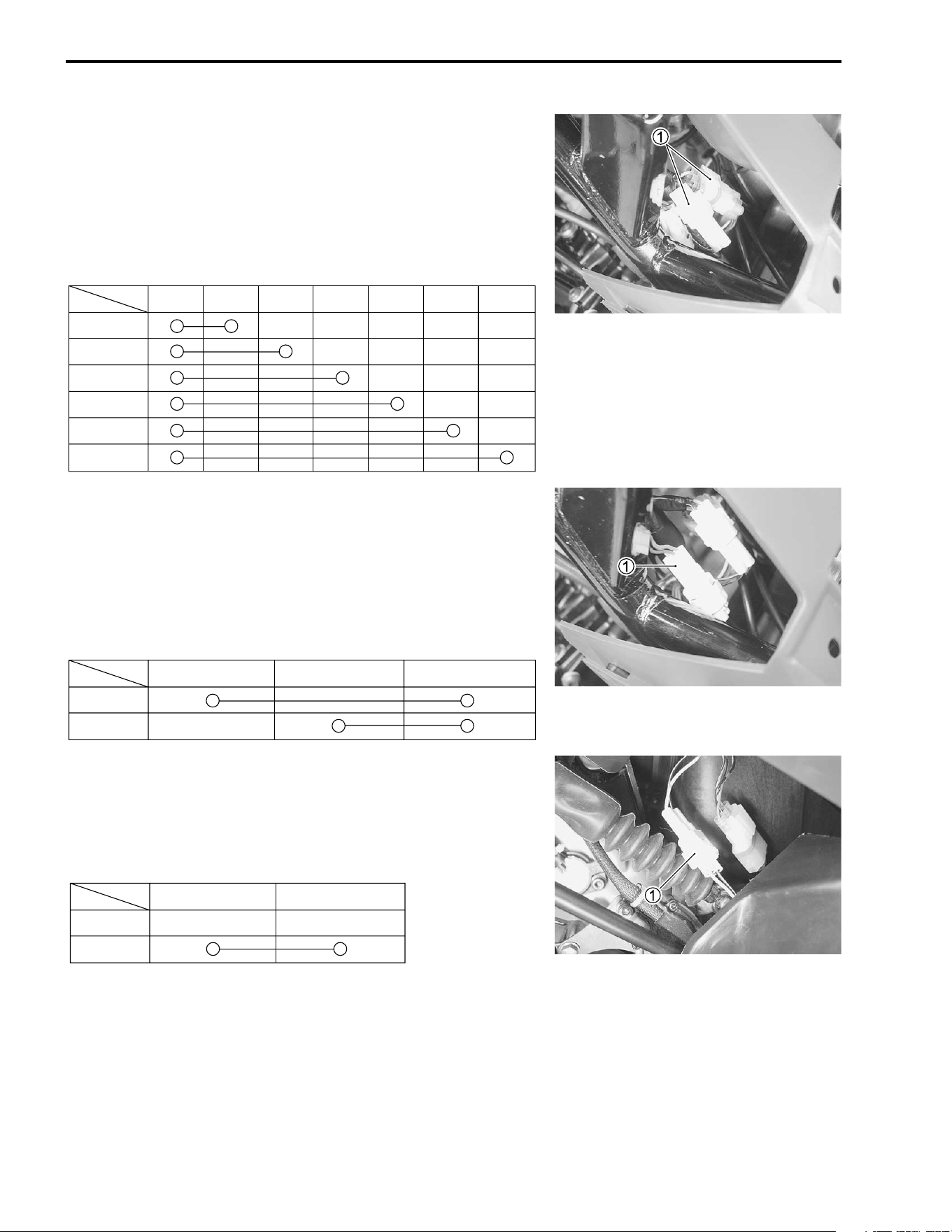
8-34 ELECTRICAL SYSTEM
NEUTRAL SWITCH
• Remove the fuel tank cover. (!7-5)
• Disconnect the neutral switch coupler
1.
Measure neutral switch for continuity using a multi circuit tester.
If there is no continuity, replace the neutral switch with a new
one.
# 09900-25008: Multi circuit tester set
REVERSE SWITCH
• Remove the fuel tank cover. (!7-5)
• Disconnect the reverse switch coupler
1.
Measure reverse switch for continuity using a multi circuit tester.
If there is no continuity, replace the reverse switch with a new
one.
# 09900-25008: Multi circuit tester set
GEAR SWITCH
• Disconnect the gear switch coupler
1.
Measure gear switch for continuity using a multi circuit tester. If
there is no continuity, replace the gear switch with a new one.
# 09900-25008: Multi circuit tester set
Color
Position
B/W Bl W/Y G/R Br/R Y/Bl G/Bl
Neutral
1
2
3
4
5
Color
Position
BRBl
Neutral
Reverse
Color
Position
W B/W
HI
LOW
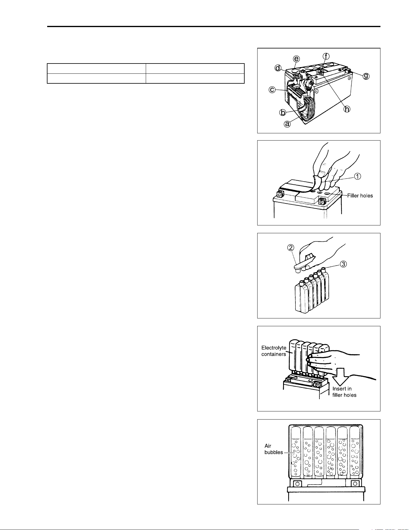
ELECTRICAL SYSTEM 8-35
BATTERY
SPECIFICATIONS
a
Anode plates
e
Stopper
b
Separator (fiberglass plate)
f
Filter
c
Cathode plates
g
Terminal
d
Upper cover breather
h
Safty valve
INITIAL CHARGING
FILLING ELECTROLYTE
• Remove the aluminum tape
1 sealing the battery electrolyte
filler holes.
• Remove the caps
2.
NOTE:
* After filling the electrolyte completely, use the removed caps
2 as the sealed caps of battery filler holes.
* Do not remove or pierce the sealed areas
3 of the electrolyte
container.
• Insert the nozzles of the electrolyte container into the battery’s
electrolyte filler holes, holding the container firmly so that it
does not fall. Take precaution not to allow any of the fluid to
spill.
• Make sure air bubbles are coming up each electrolyte con-
tainer, and leave in this position for about more than 20 min-
utes.
Type designation FTH16-BS
Capacity 12 V, 50.4 kC (14 Ah)/10 HR
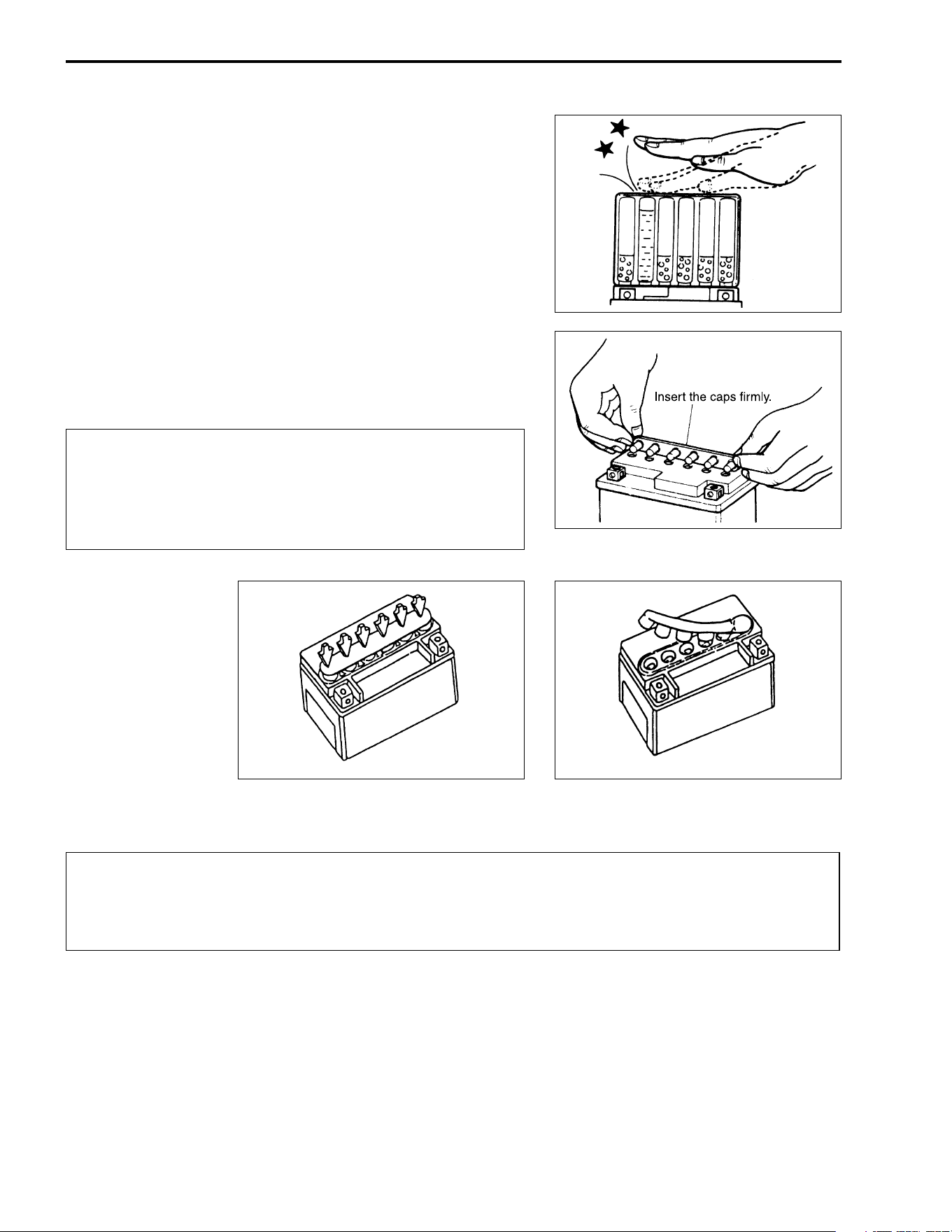
8-36 ELECTRICAL SYSTEM
NOTE:
If no air bubbles are coming up from a filler port, tap the bottom
of the electrolyte container two or three times.
Never remove the container from the battery.
• After confirming that the electrolyte has entered the battery
completely, remove the electrolyte containers from the bat-
tery. Wait for about more than 20 minutes.
• Insert the caps into the filler holes, pressing in firmly so that
the top of the caps do not protrude above the upper surface of
the battery’s top cover.
"
• For initial charging, use the charger specially designed for MF battery.
"
* Never use anything except the specified battery.
* Once install the caps to the battery; do not remove
the caps.
* Do not tap the caps with a hammer when installing
them.
INCORRECT
CORRECT
* For charging the battery, make sure to use the charger specially designed for MF battery. Oth-
erwise, the battery may be overcharged resulting in shortned service life.
* Do not remove the cap during charging.
* Position the battery with the cap facing upward during charging.
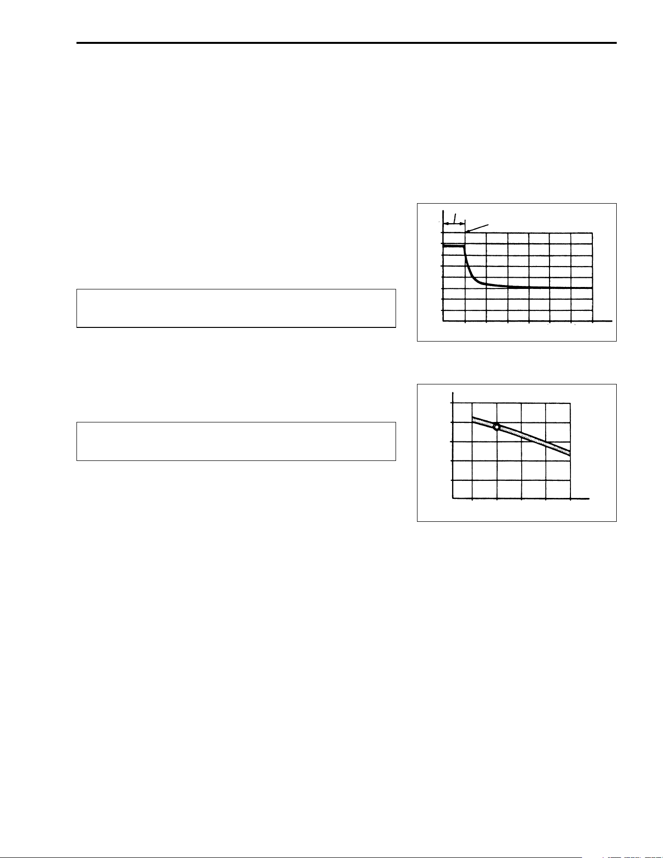
ELECTRICAL SYSTEM 8-37
SERVICING
Visually inspect the surface of the battery container. If any signs
of cracking or electrolyte leakage from the sides of the battery
have occurred, replace the battery with a new one. If the battery
terminals are found to be coated with rust or an acidic white
powdery substance, clean the battery terminals with sandpaper.
RECHARGING OPERATION
Measure the battery voltage using the multi circuit tester. If the
voltage reading is less than the 12 V (DC), recharge the battery
with a battery charger.
"
NOTE:
While recharging, do not remove the caps on the top of the bat-
tery.
Recharging time: 1.4 A for 5 to 10 hours or 7 A for 1 hour.
"
After recharging, wait at least 30 minutes and then measure the
battery voltage using the multi circuit tester. If the battery voltage
is less than 12.5 V, recharge the battery again. If the battery
voltage is still less than 12.5 V after recharging, replace the bat-
tery with a new one.
When a battery is left unused for a long time, its voltage needs
to be regularly measured. When the vehicle is not used for more
than one month (especially during the winter season), measure
the battery voltage at least once a month.
When recharging the battery, remove the battery from
the vehicle.
Be careful not to permit the charging current to
exceed 7 A at any time.
Charging period
Stop charging
18
17
16
15
14
13
12
0 10 20 30 40 50 60
Time
(Minutes)
(V)
(V)
14
13
12
11
10
100 75 50 25 0 (%)
Battery charged condition
(at 0˚C – 40˚C)

9
SERVICING INFORMATION 9-1
CONTENTS
SERVICING INFORMATION
TROUBLESHOOTING ........................................................................9- 2
ENGINE ........................................................................................9- 2
DRIVE TRAIN ...............................................................................9- 6
CARBURETOR ............................................................................9- 6
CHASSIS ......................................................................................9- 7
BRAKES ...................................................................................... 9- 8
RADIATOR (COOLING SYSTEM) ...............................................9- 8
ELECTRICAL ...............................................................................9- 9
BATTERY .....................................................................................9-10
WIRING DIAGRAM .............................................................................9-11
WIRING HARNESS, CABLE, AND HOSE ROUTING .......................9-12
WIRING HARNESS ROUTING ....................................................9-12
CABLE ROUTING ........................................................................9-15
CARBURETOR HOSE ROUTING ...............................................9-16
COOLING SYSTEM HOSE ROUTING ........................................9-18
FRONT DRIVING SYSTEM .........................................................9-19
FRONT BRAKE HOSE ROUTING ...............................................9-20
REAR BRAKE HOSE ROUTING .................................................9-21
OIL RETURN TANK HOSE ROUTING ........................................9-22
SPECIAL TOOLS ...............................................................................9-23
TIGHTENING TORQUE ......................................................................9-26
ENGINE ........................................................................................9-26
DIFFERENTIAL ............................................................................9-27
CHASSIS ......................................................................................9-27
TIGHTENING TORQUE CHART .................................................9-28
SERVICE DATA ..................................................................................9-29

9-2 SERVICING INFORMATION
TROUBLESHOOTING
ENGINE
Complaint Symptom and possible causes Remedy
Engine will not start
or is hard to start.
Compression too low
1. Worn cylinder.
2. Worn piston ring.
3. Worn valve guide or improper valve seating.
4. Loose spark plug.
5. Slow cranking starter motor.
6. Mistimed valves.
7. Valve clearance out of adjustment.
Spark plug not sparking
1. Fouled spark plug.
2. Wet spark plug.
3. Defective ignition coil.
4. Open or short in high-tension cord.
5. Defective generator.
6. Defective CDI unit.
No fuel reaching the carburetor
1. Clogged fuel tank vent hose.
2. Clogged or defective fuel valve.
3. Defective carburetor needle valve.
4. Clogged fuel hose.
5. Clogged fuel filter.
Replace.
Replace.
Repair or replace.
Tighten.
See electrical section.
Adjust.
Adjust.
Clean or replace.
Clean and dry or replace.
Replace.
Replace.
Replace.
Replace.
Clean or replace.
Clean or replace.
Replace.
Clean or replace.
Clean or replace.
Engine stalls easily. 1. Fouled spark plug.
2. Defective generator.
3. Defective CDI unit.
4. Clogged or defective fuel valve.
5. Clogged carburetor jet.
6. Valve clearance out of adjustment.
Clean or replace.
Replace.
Replace.
Clean or replace.
Clean.
Adjust.
SERVICING INFORMATION 9-3
Complaint Symptom and possible causes Remedy
Engine is noisy. Excessive valve chatter
1. Excessive valve clearance.
2. Weak or broken valve spring.
3. Worn rocker arm and rocker arm shaft.
Noise seems to come from the piston
1. Worn piston.
2. Worn cylinder.
3. Carbon build-up in combustion chamber.
4. Worn piston pin or piston pin bore.
5. Worn piston ring or ring groove.
Noise seems to come from the cam chain
1. Stretched cam chain.
2. Worn cam chain sprocket.
3. Improperly working cam chain tension adjuster.
Noise seems to come from the clutch
1. Worn crankshaft spline.
2. Worn inner race spline.
3. Worn teeth of clutch plates.
4. Distorted clutch plates, driven and drive.
5. Clutch dampers weakened.
Noise seems to come from the crankshaft
1. Rattling bearing.
2. Worn or burnt crank pin bearing.
3. Excessive thrust clearance.
Noise seems to come from transmission
1. Gears worn or rubbing.
2. Badly worn splines.
3. Primary gears worn or rubbing.
4. Badly worn bearings.
5. Worn bushing.
Noise seems to come from the transfer
1. Worn or rubbing gear.
2. Worn transfer input/output shaft.
3. Worn bearing.
4. Worn bushing.
Noise seems to come from front/rear output shaft bevel
gear, front drive (differential) bevel gear and rear drive
bevel gear
1. Worn or damage drive and driven bevel gears.
2. Excessive backlash.
3. Improper tooth contact.
4. Damage bearing.
5. Worn or rubbing gears.
6. Worn output shaft spline.
7. Front drive gear thrust clearance too large.
8. Rear drive gear thrust clearance too large.
Adjust.
Replace.
Replace.
Replace.
Replace.
Clean.
Replace.
Replace.
Replace cam chain and
sprockets.
Replace cam chain and
sprockets.
Repair or replace.
Replace crankshaft.
Replace inner race.
Replace.
Replace.
Replace.
Replace.
Replace.
Replace crankshaft or conrod.
Replace.
Replace.
Replace.
Replace.
Replace.
Replace.
Replace shaft.
Replace.
Replace.
Replace.
Adjust.
Adjust.
Replace.
Replace.
Replace output shaft.
Adjust or replace.
Adjust or replace.

9-4 SERVICING INFORMATION
Complaint Symptom and possible causes Remedy
Slipping clutch. 1. Clutch control out of adjustment or loss of play.
2. Weakened clutch springs.
3. Worn clutch shoes.
4. Worn or distorted pressure plate.
5. Distorted clutch plates, driven and drive.
Adjust.
Replace.
Replace.
Replace.
Replace.
Dragging clutch. 1. Clutch control out of adjustment or too much play.
2. Some clutch springs weakened while others are not.
3. Distorted pressure plate or clutch plates.
4. Worn or damage clutch release mechanism.
Adjust.
Replace.
Replace.
Adjust or replace.
Transmission will not
shift.
1. Broken gearshift cam.
2. Distorted gearshift forks.
3. Worn gearshift shaft.
4. Worn or damage clutch release mechanism.
5. Improperly adjusted reverse cable.
Replace.
Replace.
Replace.
Adjust or replace.
Adjust.
Transmission will not
shift back.
1. Broken reverse shift cam.
2. Shift shafts are rubbing or sticky.
3. Distorted or worn gearshift forks.
4. Broken or damaged gearshift lever return spring.
Replace.
Repair
Replace.
Replace.
Transmission jumps
out of gear.
1. Worn shifting gears on driveshaft or countershaft.
2. Distorted or worn gearshift forks.
3. Weakened cam stopper spring on gearshift cam.
4. Worn gearshift lever stopper pin.
Replace.
Replace.
Replace.
Replace.
Transfer will not shift
or shift back.
1. Broken or worn sliding dog.
2. Broken or worn gearshift fork.
3. Worn gearshift cam.
4. Weakened cam stopper spring.
5. Worn gearshift fork shaft.
Replace.
Replace.
Replace.
Replace.
Replace.
Engine idles poorly. 1. Valve clearance out of adjustment.
2. Improper valve seating.
3. Defective valve guide.
4. Worn rocker arm or rocker arm shaft.
5. Excessive spark plug gap.
6. Defective ignition coil.
7. Defective CDI unit.
8. Defective generator.
9. Incorrect float chamber fuel level.
10. Clogged carburetor jet.
11. Defective fuel valve.
12. Improperly set pilot screw.
Adjust.
Replace.
Replace.
Replace.
Adjust or replace.
Replace.
Replace.
Replace.
Adjust float height.
Clean.
Replace.
Adjust.
Engine runs poorly in
high-speed range.
1. Weak valve spring.
2. Worn camshafts or rocker arms.
3. Insufficient spark plug gap.
4. Mistimed valves.
5. Defective ignition coil.
6. Low float chamber fuel level.
7. Dirty air cleaner element.
8. Clogged fuel hose, resulting in inadequate fuel supply
to carburetor.
9. Defective fuel valve.
Replace.
Replace.
Regap or replace.
Adjust.
Replace.
Adjust float height.
Clean or replace.
Clean and prime.
Replace.

SERVICING INFORMATION 9-5
Complaint Symptom and possible causes Remedy
Exhaust smoke is
dirty or thick.
1. Excessive amount of engine oil.
2. Worn piston ring or cylinder.
3. Worn valve guide.
4. Scored or scuffed cylinder wall.
5. Worn valve stem.
6. Defective valve stem oil seal.
Check level and drain.
Replace.
Replace.
Replace.
Replace.
Replace.
Engine lacks power. 1. Insufficient valve clearance.
2. Weak valve spring.
3. Mistimed valves.
4. Worn cylinder.
5. Worn piston ring.
6. Improper valve seating.
7. Fouled spark plug.
8. Incorrect spark plug gap.
9. Clogged carburetor jet.
10. Incorrect float chamber fuel level.
11. Dirty air cleaner element.
12. Worn rocker arm or shaft.
13. Air leakage from intake pipe.
14. Excessive amount of engine oil.
Adjust.
Replace.
Adjust.
Replace.
Replace.
Repair.
Clean or replace.
Adjust or replace.
Clean.
Adjust float height.
Clean or replace.
Replace.
Tighten or replace.
Check level and drain.
Engine overheats. 1. Carbon build-up on piston crown.
2. Insufficient amount of engine oil.
3. Defective oil pump.
4. Clogged oil circuit.
5. Float chamber fuel level too low.
6. Air leakage from intake pipe.
7. Incorrect engine oil.
Clean.
Check level and add.
Replace.
Clean.
Adjust float height.
Tighten or replace.
Change.

9-6 SERVICING INFORMATION
DRIVE TRAIN
CARBURETOR
Complaint Symptom and possible causes Remedy
Power will not trans-
mit from the engine to
the rear wheel.
1. Broken drive and driven bevel gear teeth.
2. Broken rear output shaft.
3. Worn or broken rear axle serration.
4. Worn or damaged coupling joint serration.
5. Broken or damaged rear drive and driven bevel gears.
6. Worn or damaged universal joint.
Replace.
Replace.
Replace.
Replace.
Replace.
Replace.
Power will not trans-
mit from engine to the
front wheel.
1. Broken drive and driven bevel gear teeth.
2. Worn or broken propeller shaft serration.
3. Damaged coupling.
4. Worn or damaged coupling joint serration.
5. Broken or dameged front drive (differential) gear or pin-
ion.
6. Improperly operated front drive (differential) shifting
motor.
7. Worn or damaged shifting sleeve, shaft and fork of the
2WD/4WD shifting.
8. Worn or damaged universal joint.
9. Worn or damaged front axle or universal joint serration.
Replace.
Replace.
Replace.
Replace.
Replace.
Repair or replace.
Replace.
Replace.
Replace.
Complaint Symptom and possible causes Remedy
Starting difficulty. 1. Clogged starter jet.
2. Clogged starter jet passage.
3. Air leaking from joint between starter body and carbure-
tor.
4. Improperly working starter (enricher) plunger.
Clean.
Clean.
Tighten, adjust or replace gas-
ket.
Adjust.
Idling or low-speed
trouble.
1. Clogged or loose slow jet.
2. Clogged pilot jet passage.
3. Clogged pilot outlet port.
4. Clogged bypass port.
5. Starter (enricher) plunger not fully closed.
6. Improperly set pilot screw.
7. Incorrect float height.
Clean or tighten.
Clean.
Clean.
Clean.
Adjust.
Adjust.
Adjust.
Medium-or high
speed trouble.
1. Clogged main jet.
2. Clogged main air jet.
3. Clogged needle jet.
4. Improperly working throttle valve.
5. Clogged fuel filter.
6. Incorrect float height.
7. Starter (enricher) plunger not fully closed.
Clean.
Clean.
Clean.
Adjust.
Clean or replace.
Adjust.
Adjust.
Overflow and fuel
level fluctuations.
1. Worn or damaged needle valve.
2. Broken needle valve spring.
3. Improperly working float.
4. Foreign matter on the needle valve.
5. Incorrect float chamber fuel level.
Replace.
Replace.
Adjust or replace.
Clean or replace with needle
valve seat.
Adjust float height.

SERVICING INFORMATION 9-7
CHASSIS
Complaint Symptom and possible causes Remedy
Handling is too heavy
or stiff.
1. Improper front wheel alignment.
2. Insufficiently lubricated.
3. Low air pressure in front tires.
4. Tie rod ends tending to seize.
5. Linkage connections tending to seize.
Adjust.
Lubricate.
Adjust.
Replace.
Repair or replace.
Steering wobbles. 1. Unequally inflated tires.
2. Loose front wheel hub nuts.
3. Damaged or worn front wheel hub bearings.
4. Worn or loose tie rod ends.
5. Defective or incorrect front tires.
6. Damaged or worn wishbone arms and related bush-
ings.
7. Distorted front wheels.
8. Loose chassis nuts and bolts.
Regulate.
Tighten.
Replace.
Replace or tighten.
Replace.
Replace.
Replace.
Replace.
Tighten.
Steering pulls to one
side.
1. Unequally inflated tires.
2. Improper front wheel alignment.
3. Worn front wheel hub bearings.
4. Distorted frame.
5. Defective shock absorber.
Regulate.
Adjust.
Replace.
Repair or replace.
Replace.
Shocks felt in the
steering.
1. High tire pressure.
2. Worn steering linkage connections.
3. Loose suspension system bolts.
Regulate.
Replace.
Tighten.
Tires rapidly or
unevenly wear.
1. Worn or loose front wheel hub bearings.
2. Improper front wheel alignment.
Replace.
Adjust.
Steering too noisy. 1. Loose nuts and bolts.
2. Damaged or worn front wheel hub bearings.
3. Insufficiently lubricated.
Tighten.
Replace.
Lubricate.
Suspension too soft. 1. Weakened spring.
2. Shock absorber leaks oil.
3. Improper suspension setting.
Replace.
Replace.
Adjust.
Suspension too stiff. 1. Worn upper or lower wishbone arms and related bush-
ings.
2. Improper suspension setting.
3. Bent shock absorber rod.
Tighten.
Adjust.
Replace.
Suspension too
noisy.
1. Loose suspension system bolts.
2. Worn wishbone arms and related bushings.
3. Worn swingarm bearings.
Tighten.
Replace.
Replace.
Rear wheels wobble. 1. Distorted rear wheel rims.
2. Damage or worn rear wheel hub bearings.
3. Defective or incorrect rear tires.
4. Loose rear wheel hub nuts.
5. Loose rear axle shaft nut.
6. Loosen rear axle housing mounting bolts.
7. Improper rear brake adjustment.
8. Damaged or worn rear swingarm and related bushings.
9. Rear shock absorber leaks oil.
10. Loose rear swingarm nut.
Replace.
Replace.
Replace.
Tighten.
Tighten.
Tighten.
Adjust.
Replace.
Replace.
Tighten.

9-8 SERVICING INFORMATION
BRAKES
RADIATOR (COOLING SYSTEM)
Complaint Symptom and possible causes Remedy
Poor braking. 1. Insufficient brake fluid.
2. Air in brake fluid circuit.
3. Worn pads.
4. Too much play on brake pedal.
Refill to level mark.
Bleed air out.
Replace.
Adjust.
Insufficient brake
power.
1. Leakage of brake fluid from hydraulic system.
2. Worn pads.
3. Oil adhesion on engaging surface of pads.
4. Worn disc.
5. Air in hydraulic system.
Repair or replace.
Replace.
Clean disc and pads.
Replace.
Bleed.
Brake squeaks. 1. Carbon adhesion on pad surface.
2. Titled pad.
3. Loose front wheel axle or rear wheel axle.
4. Worn brake pads.
5. Foreign material in brake fluid.
6. Clogged return port of master cylinder.
7. Caliper binding on caliper axles.
Repair surface with emery
paper.
Modify pad fitting or replace.
Tighten to specified torque.
Replace.
Replace brake fluid.
Disassemble and clean master
cylinder.
Clean and lubricate.
Excessive brake lever
stroke.
1. Air in hydraulic system.
2. Insufficient brake fluid.
3. Improper quality of brake fluid.
Bleed.
Replenish fluid to specified
level and bleed air.
Replace with correct fluid.
Brake fluid leakage. 1. Insufficient tightening of connection joints.
2. Cracked hose.
3. Worn piston and/or cup.
Tighten to specified torque and
add brake fluid.
Replace.
Replace piston and/or cup.
Complaint Symptom and possible causes Remedy
Engine overheats.
1. Not enough engine coolant.
2. Clogged radiator core with dirt or scale.
3. Fautly cooling fan.
4. Defective cooling fan thermo-switch.
5. Clogged water passage.
6. Air trapped in the cooling circuit.
7. Defective water pump.
8. Use of incorrect coolant.
9. Defective thermostat.
Add coolant.
Clean.
Repair or replace.
Replace.
Clean.
Bleed air.
Replace.
Replace.
Replace.
Engine overcools.
1. Defective cooling fan thermo-switch.
2. Extremely cold weather.
3. Defective thermostat.
Replace.
Put on radiator cover.
Replace.

SERVICING INFORMATION 9-9
ELECTRICAL
Complaint Symptom and possible causes Remedy
No sparking or poor
sparking.
1. Defective ignition coil.
2. Defective spark plug.
3. Defective generator.
4. Defective CDI unit.
5. Defective pickup coil or power source coil.
Replace.
Replace.
Replace.
Replace.
Replace.
Spark plug is wet or
quickly becomes
fouled with carbon.
1. Excessively rich air/fuel mixture.
2. Excessively high idling speed.
3. Incorrect gasoline.
4. Dirty air cleaner element.
5. Incorrect spark plug (cold type).
Adjust carburetor.
Adjust carburetor.
Change.
Clean or replace.
Change to standard spark
plug.
Spark plug quickly
becomes fouled with
oil or carbon.
1. Worn piston ring.
2. Worn piston.
3. Worn cylinder.
4. Excessive valve-stem-to-valve-guide clearance.
5. Worn valve stem oil seal.
Replace.
Replace.
Replace.
Replace.
Replace.
Spark plug electrodes
overheat or burn.
1. Incorrect spark plug.
2. Overheated engine.
3. Loose spark plug.
4. Excessively lean air/fuel mixture.
Change to cold type spark
plug.
Tu r n- u p.
Tighten.
Adjust carburator.
Generator does not
charge.
1. Open or short in lead wires, or loose lead connections.
2. Shorted, grounded or open generator coil.
3. Shorted or punctured regulator/rectifier.
Repair, replace or connect
properly.
Replace.
Replace.
Generator charges
but charging rate is
below specification.
1. Lead wires tend to get shorted, open-circuited, or
loosely connected at terminal.
2. Grounded or open-circuited stator coils or generator.
3. Defective regulator/rectifier.
Repair or tighten.
Replace.
Replace.
Generator over-
charges.
1. Internal short-circuit in the battery.
2. Damaged or defective regulator/rectifier.
Replace battery.
Replace.
Unstable charging. 1. Lead wire insulation frayed due to vibration, resulting in
intermittent shorting.
2. Internally shorted generator.
3. Defective regulator/rectifier.
Repair or replace.
Replace.
Replace.
Starter button does
not work.
1. Run down battery.
2. Defective switch contact.
3. Brushes do not seat properly on the commutator in the
starter motor.
4. Defective starter relay.
5. Defective parking brake switch.
6. Wiring connections loose or disconnected.
Recharge or replace.
Replace.
Repair or replace.
Replace.
Replace.
Connect, tighten or repair.
2WD/4WD button
does not work.
1. Defective 2WD/4WD selecting relay.
2. Defective 2WD switch or 4WD switch.
3. Wiring connections loose or disconnected.
Replace.
Replace.
Connect, tighten or repair.

9-10 SERVICING INFORMATION
BATTERY
Complaint Symptom and possible causes Remedy
Sulfation or spots on
surfaces of cell
plates.
1. Cracked battery case.
2. Battery has been left in a run-down condition for a long
time.
Replace.
Replace.
Battery runs down
quickly.
1. Incorrect charging method.
2. Battery cell plates have lost much of their active mate-
rial as a result of overcharging.
3. Internally shorted battery.
4. Old battery.
Check the generator, and regu-
lator/rectifier circuit connec-
tions, and make necessary
adjustments to obtain specified
charging operation.
Replace the battery and cor-
rect the charging system.
Replace.
Replace.
Reversed battery
polarity.
1. Improperly connected battery leads.
(i.e.,
-
to
+
and
+
to
-
)
Replace the battery and be
sure to connect it properly.
Battery discharged
too rapidly.
1. Dirty container top and sides.
2. Old battery.
Clean.
Replace.
Battery sulfation. 1. Incorrect charging rate.
(When not in use, the battery should be checked at
least once a month and properly charged if necessary,
to avoid sulfation.)
2. The battery was left unused for too long.
Replace.
Replace the battery if badly
sulfated.
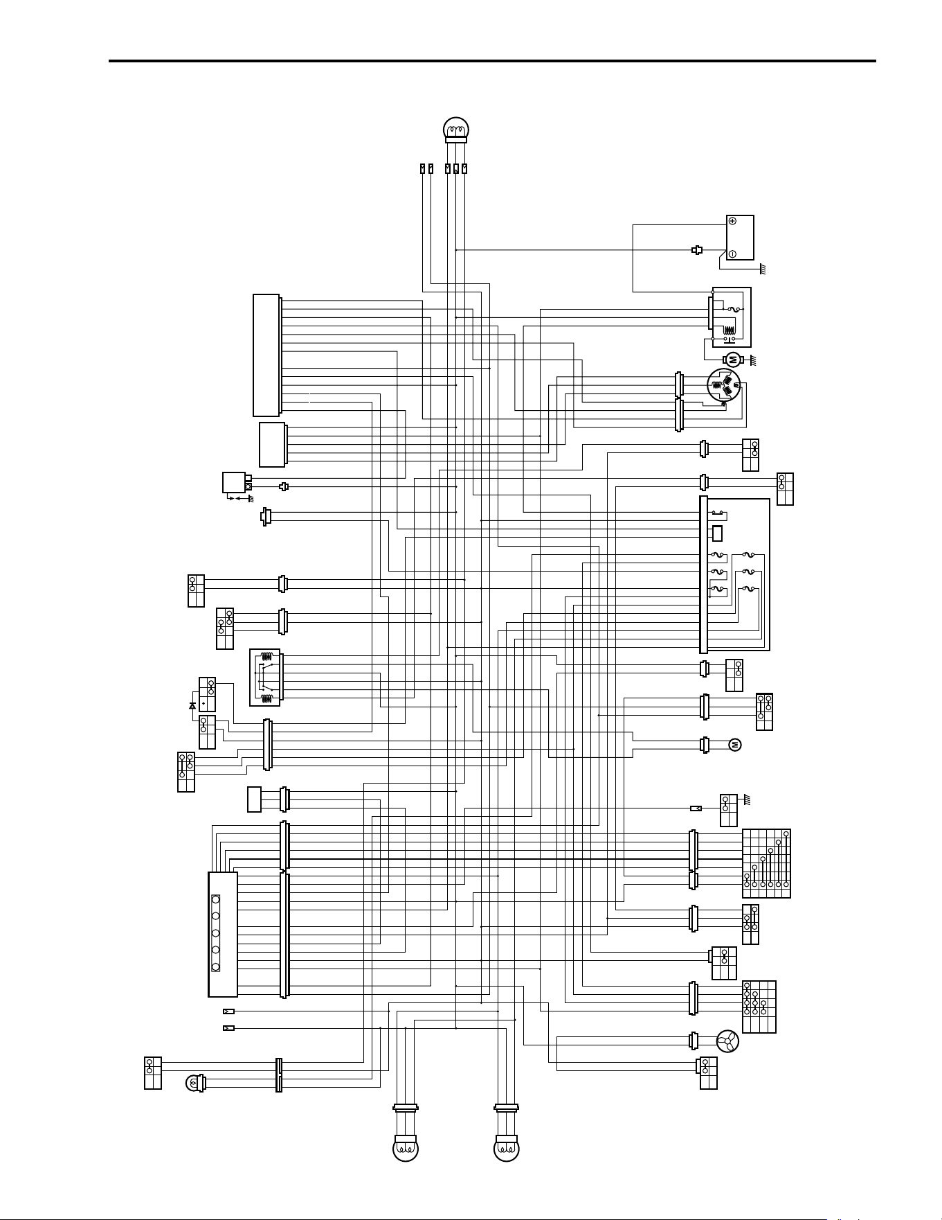
SERVICING INFORMATION 9-11
WIRING DIAGRAM
P
R
N
B
W
: PARKING INDICATOR LIGHT
: REVERSE INDICATOR LIGHT
: NEUTRAL INDICATOR LIGHT
: HIGH BEAM INDICATOR LIGHT
: ENGINE COOLANT TEMPERATURE INDICATOR LIGHT
HEADLIGHT(R)
HEADLIGHT(L)
AUXILIARY LIGHT
FRONT BRAKE
SWITCH
SPEEDOMETER
ENGINE
STOP
SWITCH
HANDLE SWITCH
DIMMER
SWITCH
PARKING/
NEUTRAL
POSITION
SWITCH
REAR BRAKE
SWITCH
SPEED
SENSOR
STARTER
BUTTON
POWER
SOURCE
CDI UNIT
REGULATOR/
RECTIFIER
IGNITION
COIL
2WD/4WD
SELECTING RELAY
BRAKE LIGHT/TAILLIGHT
OPTION
GENERATOR
STARTER
MOTOR
STARTER RELAY
BATTERY
1 . MAIN 30A
1
2WD
SWITCH
4WD
SWITCH
1 . HEAD HI
2 . HEAD LO
3 . TAIL
4 . IGNITION
5 .
P-SOURCE
6 . AUX
10A
10A
10A
15A
10A
10A
GEAR
SWITCH
REVERSE
SWITCH
FUSE BOX
2WD/4WD
MOTOR
FAN
MOTOR
COOLING FAN
THERMO-SWITCH
ENGINE
COOLANT
TEMPERATURE
SWITCH
PARKING
BRAKE
SWITCH
NEUTRAL SWITCH
IGNITION SWITCH
2WD/4WD
SELECTING
BUTTON
B
Bl
G
Gr
Lbl
O
P
R
W
Y
V
B/Bl
B/G
B/R
B/W
R/W
Bl/G
Bl/R
Bl/W
Br/R
G/Bl
G/R
G/W
O/B
O/Bl
O/R
O/W
O/Y
P/B
P/Bl
R/B
W/B
W/Bl
W/G
W/R
W/Y
Y/B
Y/Bl
Y/G
Y/W
: Black
: Blue
: Green
: Gray
: Light Blue
: Orange
: Pink
: Red
: White
: Yellow
: Violet
: Black with Blue tracer
: Black with Green tracer
: Black with Red tracer
: Black with White tracer
: Red with White tracer
: Blue with Green tracer
: Blue with Red tracer
: Blue with White tracer
: Brown with Red tracer
: Green with Blue tracer
: Green with Red tracer
: Green with White tracer
: Orange with Black tracer
: Orange with Blue tracer
: Orange with Red tracer
: Orange with White tracer
: Orange with Yellow tracer
: Pink with Black tracer
: Pink with Blue tracer
: Red with Black tracer
: White with Black tracer
: White with Blue tracer
: White with Green tracer
: White with Red tracer
: White with Yellow tracer
: Yellow with Black tracer
: Yellow with Blue tracer
: Yellow with Green tracer
: Yellow with White tracer
WIRE COLORS
123
456
ON
OFF
P
R
NB
W
HI
LO
RUN
OFF
PUSH
OFF
ON
ON
OFF
2WD
4WD
2WD
4WD
HI
LOW
N
R
ON
OFF
N
1
2
3
4
5
2WD
4WD
OFF
ON
ON
OFF
RB
ON 3
ON 2
ON 1
OFF
12V
B/W
B/W
P/B
P/B
O/Y
O/Y
W/B
W/B
B/W
B/W
P
B
B
B/W
B/W
Bl/R
Bl/R
G
R
R/B
R/B
P/Bl
P/Bl
P
Bl
Bl
W
Gr
Gr
B/Bl
B/Bl
W/G
W/G
Lbl
Lbl
Y
Y/W
Y/W
G/R
G/R
Br/R
Br/R
Y/Bl
Y/Bl
G/Bl
G/Bl
Bl/W
Bl/W
Bl/R
Bl/R
V
R
O/Y
O/Y
O/B
O/B
P/B
P/B
B/R
B/R
W
Gr
Gr
B/W
B/W
G/W
G/W
B/G
B/G
Y
W/Y
W/Y
G/R
G/R
Br/R
Br/R
Y/Bl
Y/Bl
G/Bl
G/Bl
Bl
Bl
O/B
O/B
P/B
P/B
B/W
B/W
Y/Bl
Y/Bl
W/Bl
W/Bl
O/Bl
O/Bl
O/Y
O/Y
O/W
O/W
Y/G
Y/G
B
R/B
R/B
O/Y
O/Y
B/W
B/W
B/R
B/R
Bl/R
Bl/R
O/Y
O/Y
V
B/Bl
B/Bl
O
V
O/Y
O/Y
W/B
W/B
O/W
O/W
B/W
B/W
B/W
B/W
W/Bl
W/Bl
B
B
B
R
B/W
B/W
W/Bl
W/Bl
O/W
O/W
O/W
O/W
B/W
B/W
B
Bl/R
Bl/R
B/Bl
B/Bl
Y
Bl/G
Bl/G
Bl
Bl
V
G
W/G
W/G
B/W
B/W
Bl
Bl
O
W/B
W/B
O/R
O/R
P
B/W
B/W
Y
W
Gr
Gr
O
O/W
O/W
Y/G
Y/G
O/Y
O/Y
Bl/R
Bl/R
Gr
Gr
B/W
B/W
W/B
W/B
Gr
Gr
B/W
B/W
W/B
W/B
Y
B/W
B/W
W
Y
B/W
B/W
W
Y
B/W
B/W
W
Y
B/W
B/W
W
B/R
B/R
O/Y
O/Y
B/W
B/W
B/R
B/R
R
O
O/Bl
O/Bl
P
O/Y
O/Y
B
O/Y
O/Y
B/R
B/R
Bl
Bl
O
B
Bl
Bl
B/W
B/W
R/B
R/B
W/Y
W/Y
G/R
G/R
Br/R
Br/R
Y/Bl
Y/Bl
G/Bl
G/Bl
B/G
B/G
R/B
R/B
B/R
B/R
R/B
R/B
B/R
B/R
Bl
Bl
Bl/R
Bl/R
R/B
R/B
W
B/W
B/W
Gr
Gr
W
Y
Y/Bl
Y/Bl
W/Bl
W/Bl
O/Bl
O/Bl
O
O/Y
O/Y
O/W
O/W
P
P/B
P/B
Y/G
Y/G
B/Bl
B/Bl
O/Y
O/Y
Y/B
Y/B
Bl
Bl
B
R/W
R/W
R/W
R/W
B/R
B/R
Bl/R
Bl/R
Y
W/G
W/G
Bl/G
Bl/G
G
B
B
B
Y/B
Y/B
B/W
B/W
R
B/W
B/W
B/W
B/W
Y
W
Bl
Bl
G
B
B
B
R/W
R/W
R/W
R/W
W
B/W
B/W
B
R
Bl
Bl
B
B/W
B/W
Bl
Bl
W/Y
W/Y
G/R
G/R
Br/R
Br/R
Y/Bl
Y/Bl
G/Bl
G/Bl
R
O
Gr
Gr
P
B
Bl
Bl
B/W
P/B
O/Y
W/B
B/W
P
B
B
B/W
Bl/R
G
R
R/B
P/Bl
P
Bl
W
Gr
B/Bl
W/G
Lbl
Y
Y/W
G/R
Br/R
Y/Bl
G/Bl
Bl/W
Bl/R
V
R
O/Y
O/B
P/B
B/R
W
Gr
B/W
G/W
B/G
Y
W/Y
G/R
Br/R
Y/Bl
G/Bl
Bl
O/B
P/B
B/W
Y/Bl
W/Bl
O/Bl
O/Y
O/W
Y/G
B
R/B
O/Y
B/W
B/R
Bl/R
O/Y
V
B/Bl
O
V
O/Y
W/B
O/W
B/W
B/W
W/Bl
B
B
B
R
B/W
W/Bl
O/W
G/W
B/W
B
Bl/R
B/Bl
Y
Bl/G
Bl
V
G
W/G
B/W
Bl
O
W/B
R/B
P
B/W
Y
W
Gr
O
O/W
Y/G
O/Y
Bl/R
Gr
B/W
W/B
Gr
B/W
W/B
Y
B/W
W
Y
B/W
W
Y
B/W
W
Y
B/W
W
B/R
O/Y
B/W
B/R
R
O
O/Bl
P
O/Y
B
O/Y
B/R
Bl
O
B
Bl
B/W
R/B
W/Y
G/R
Br/R
Y/Bl
G/Bl
B/G
R/B
B/R
R/B
B/R
Bl
Bl/R
R/B
W
B/W
Gr
W
Y
Y/Bl
W/Bl
O/Bl
O
O/Y
O/W
P
P/B
Y/G
B/Bl
O/Y
Y/B
Bl
B
R/W
R/W
B/R
Bl/R
Y
W/G
Bl/G
G
B
B
B
Y/B
B/W
R
B/WB/W
Y
W
Bl
G
B
B
B
R/W
R/W
W
B/W
B
R
Bl
B
B/W
Bl
W/Y
G/R
Br/R
Y/Bl
G/Bl
R
O
Gr
P
B
Bl
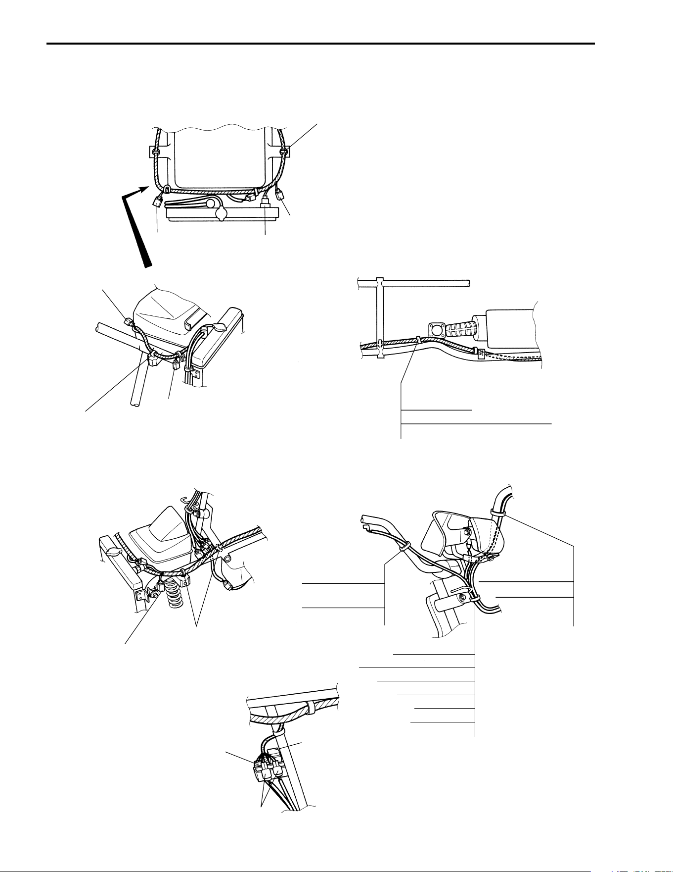
9-12 SERVICING INFORMATION
WIRING HARNESS, CABLE, AND HOSE ROUTING
WIRING HARNESS ROUTING
Fix the wiring harness
clamp to the frame.
To headlight (LH)
Cooling fan thermo-switch
To headlight (RH)
To power source
Fix the wiring harness
clamp to the frame.
To headlight (RH)
Wiring harness
Engine coolant temperature switch
Clamp
To headlight (LH)
Fix the wiring harness
clamp to the frame.
Speedometer
Ignition switch
Clamp
Handlebar switch (LH)
Rear brake switch
Front brake switch
2WD/4WD selecting button
Front brake switch
2WD/4WD
selecting button
Clamp
2WD/4WD selecting relay
2WD/4WD motor
2WD/4WD switch coupler
Clamp
Handlebar switch (LH)
Rear brake switch
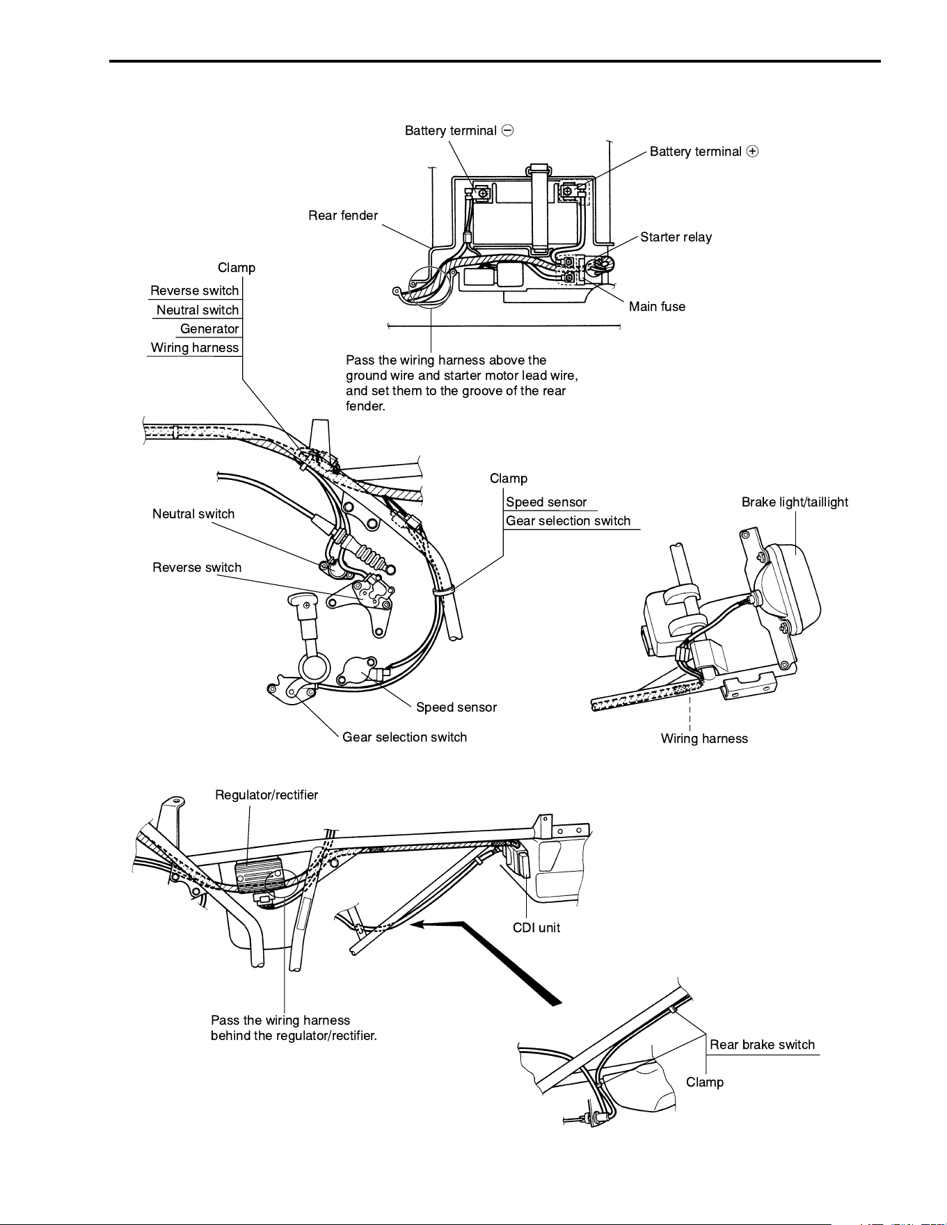
SERVICING INFORMATION 9-13
Battery terminal
+
Battery terminal
-
Rear fender
Main fuse
Starter relay
Pass the wiring harness above the
ground wire and starter motor lead wire,
and set them to the groove of the rear
fender.
Neutral switch
Reverse switch
Regulator/rectifier
Pass the wiring harness
behind the regulator/rectifier.
CDI unit
Rear brake switch
Clamp
Wiring harness
Brake light/taillight
Speed sensor
Speed sensor
Gear selection switch
Gear selection switch
Clamp
Reverse switch
Neutral switch
Generator
Clamp
Wiring harness
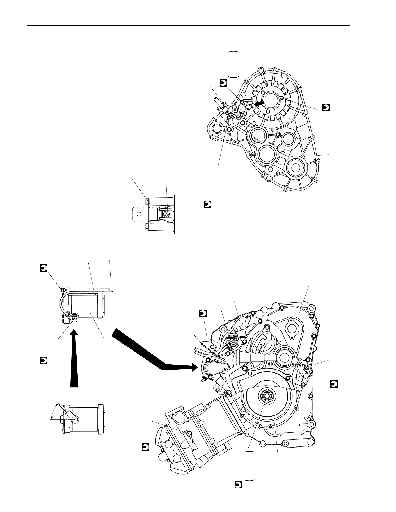
9-14 SERVICING INFORMATION
45˚
AA
VIEW A
Starter motor
5 N·m
(0.5 kgf-m, 3.7 lb-ft)
Gromet
6.5 N·m
(0.65 kgf-m, 4.7 lb-ft)
Reverse switch
Neutral switch
5 N·m
0.5 kgf-m
3.7 lb-ft
6 N·m
(0.6 kgf-m, 4.3 lb-ft)
10 N·m
(1.0 kgf-m, 7.0 lb-ft)
Ground wire
Starter motor lead wire
Clamp
Generator lead wire
10 N·m
(1.0 kgf-m, 7.0 lb-ft)
Transfer cover
Engine coolant temperature switch
10 N·m (1.0 kgf-m, 7.0 lb-ft)
Generator
rotor
4 N·m (0.4 kgf-m, 3.0 lb-ft)
Transfer cover
Reverse cable braket
160 N·m
16.0 kgf-m
115.5 lb-ft
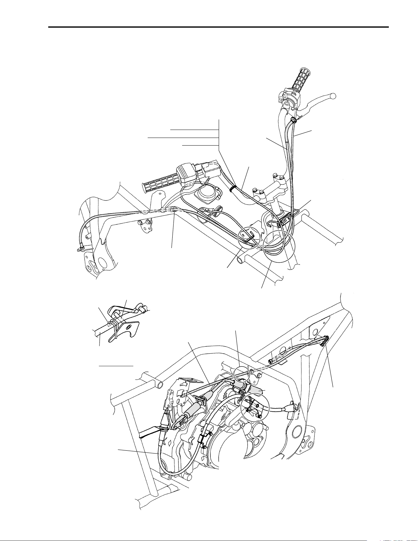
SERVICING INFORMATION 9-15
CABLE ROUTING
Clamp
Pass the throttle cable and the starter cable
through the cable guide.
Pass the throttle cable front of the rear brake cable.
Pass the starter cable back of the rear brake cable.
Cable guide
Throttle cable
Rear brake cable
Clamp
Front brake switch
2WD/4WD selecting button
Throttle cable
Starter cable
Cable guide
Pass the parking cable
over the reverse shaft.
Parking cable
Parking cable
Parking interlock cable
Pass the parking interlock cable
over the engine mounting bracket.
Clamp the parking
interlock cable
at the protecter.
A
DETAIL A
Reverse
cable
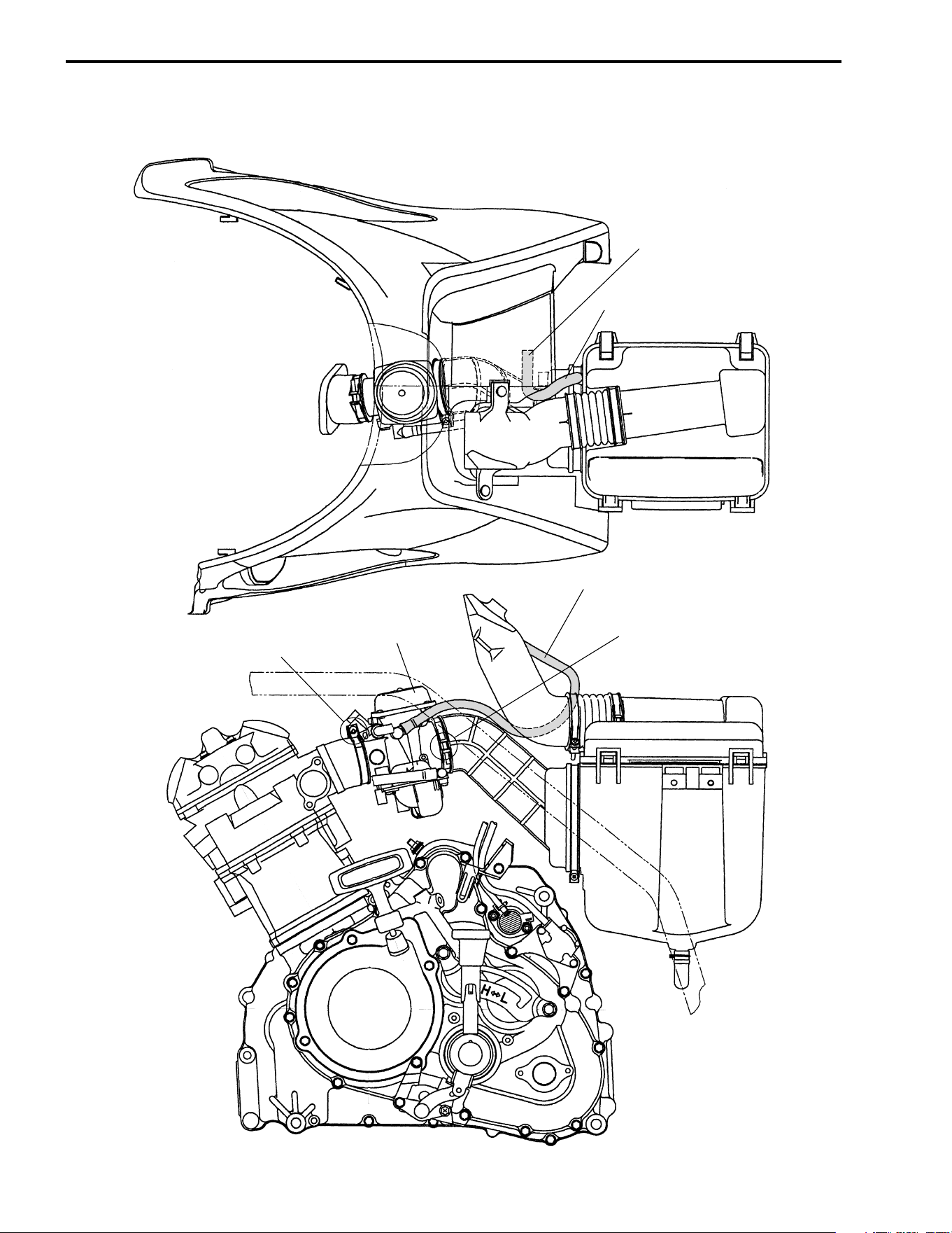
9-16 SERVICING INFORMATION
CARBURETOR HOSE ROUTING
Insert the air vent hose
into the fuel tank cover.
Air vent hose
Carburetor
Face the clamp
screw head left side.
Face the clamp
screw head up ward.
Air vent hose
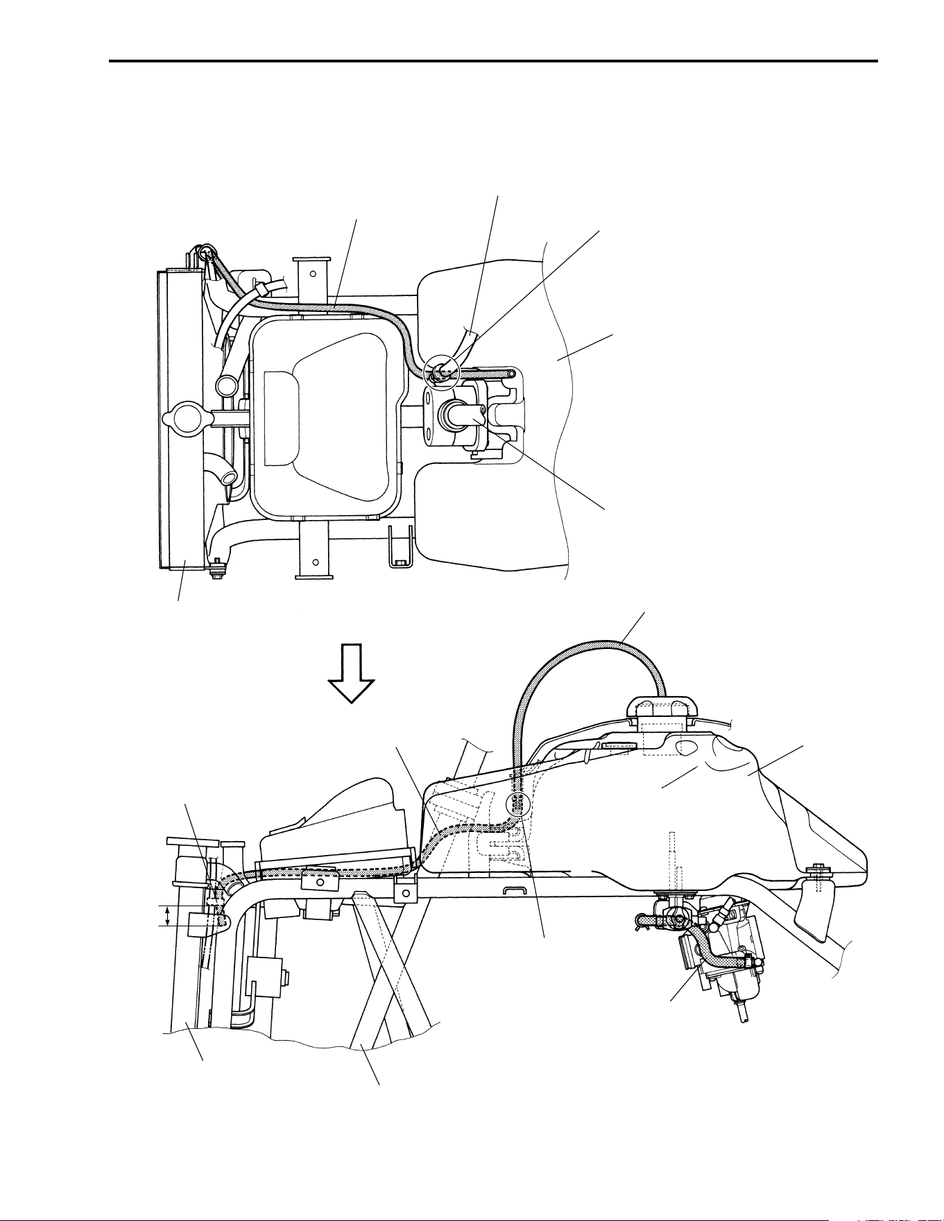
SERVICING INFORMATION 9-17
Pass the breather hose No.2
the right of the brake hose.
Fuel tank
Steering shaft
Radiator
Clamp the breather hose No.2
at 20 mm (0.8 in) from hose end.
20mm
(0.8 in)
Radiator
Steering shaft
Connect the breather hose No.2
to the fuel tank top cover.
Fuel tank
Breather hose No.1
Fuel hose
Breather hose No.2
Breather hose No.2
Brake hose
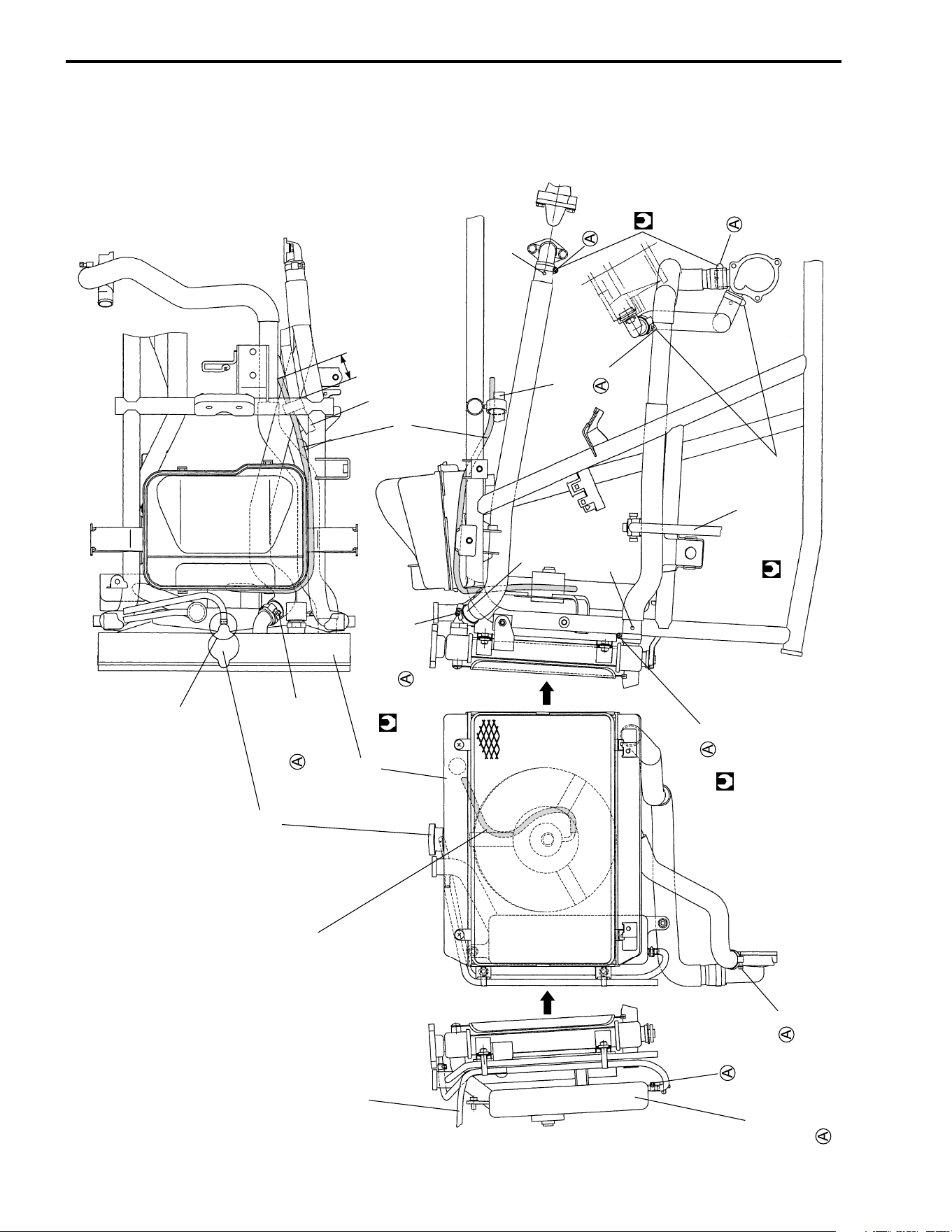
9-18 SERVICING INFORMATION
COOLING SYSTEM HOSE ROUTING
Marking
2.0 N·m
(0.2 kgf-m, 1.5 lb-ft)
2.0 N·m (0.2 kgf-m, 1.5 lb-ft)
Cooling fan breather hose
Wiring harness
40 mm (1.6 in)
Wiring harness
Downward
Backward
Downward
Brake hose
Marking
Marking
Face the clip end downward.
Radiator cap
Left side
Upward
Radiator
Reservoir tank
Forward
Upward
Downward
Fuel tank breather hose No.2
: The ends of the clamp should face - - - - - - -
Cooling fan breather hose
2.0 N·m
0.2 kgf-m,
1.5 lb-ft
( )
2.0 N·m
(0.2 kgf-m, 1.5 lb-ft)
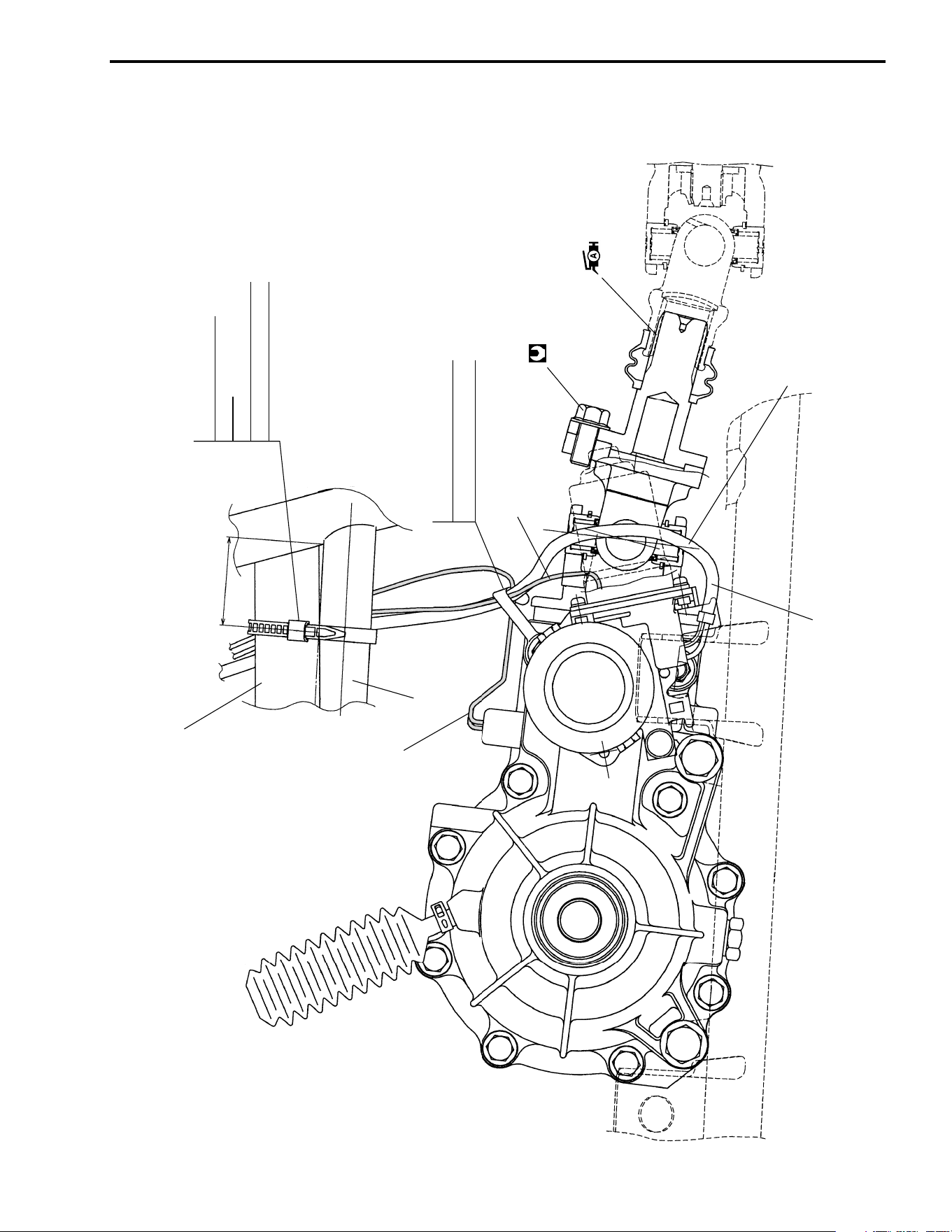
SERVICING INFORMATION 9-19
FRONT DRIVING SYSTEM
45 N
.
m
(4.5 kgf-m, 32.5 lb-ft)
Radiator outlet hose
40 – 50 mm
(1.6 – 2.0 in)
Frame
4WD switch harness
2WD/4WD motor harness
2WD switch harness
Clamp
2WD/4WD switch harness
2WD/4WD motor harness
Pass the motor harness between
motor and yoke.
Clamp
Radiator outlet hose
Frame
2WD/4WD switch harness
2WD/4WD motor harness
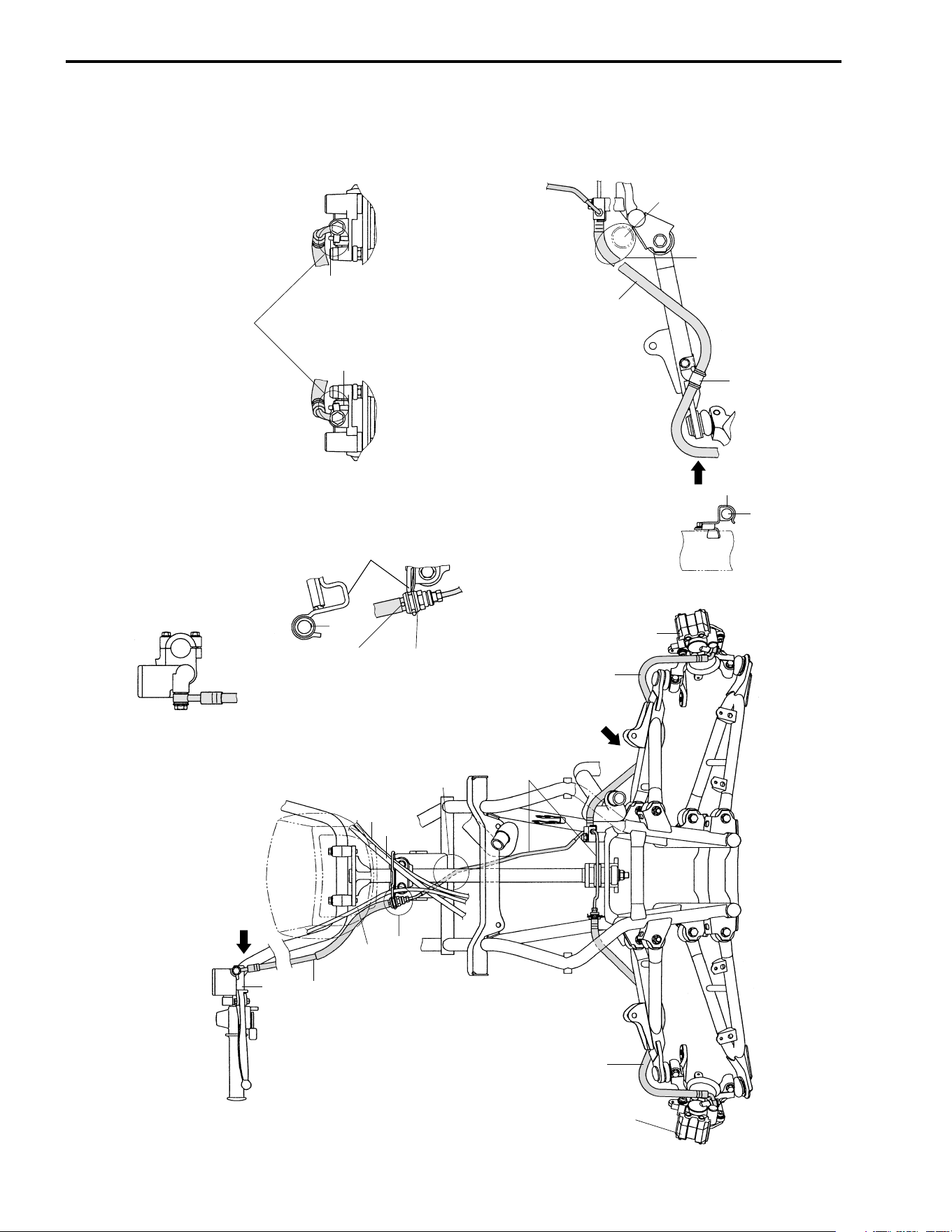
9-20 SERVICING INFORMATION
FRONT BRAKE HOSE ROUTING
Front brake master
cylinder
Brake hose
Throttle cable
B
Starter cable
Rear brake cable
Pass the brake pipe
behind the steering shaft.
Brake pipe
C
Brake hose
Brake
caliper (L)
Brake hose
Brake
caliper (R)
A
VIEW A
DETAIL B
VIEW D VIEW C
Face the white mark on the
brake hose to the forward.
Hose guide
After touching the brake hose union
to the stopper, tighten the union bolt
to the specified torque.
Stopper
Stopper
Front brake caliper (R) Front brake caliper (L)
Brake hose
Clamp
Clamp
D
Brake hose
Radiator
outlet hose
Pass the brake hose above
the radiator outlet hose.
Cable guide
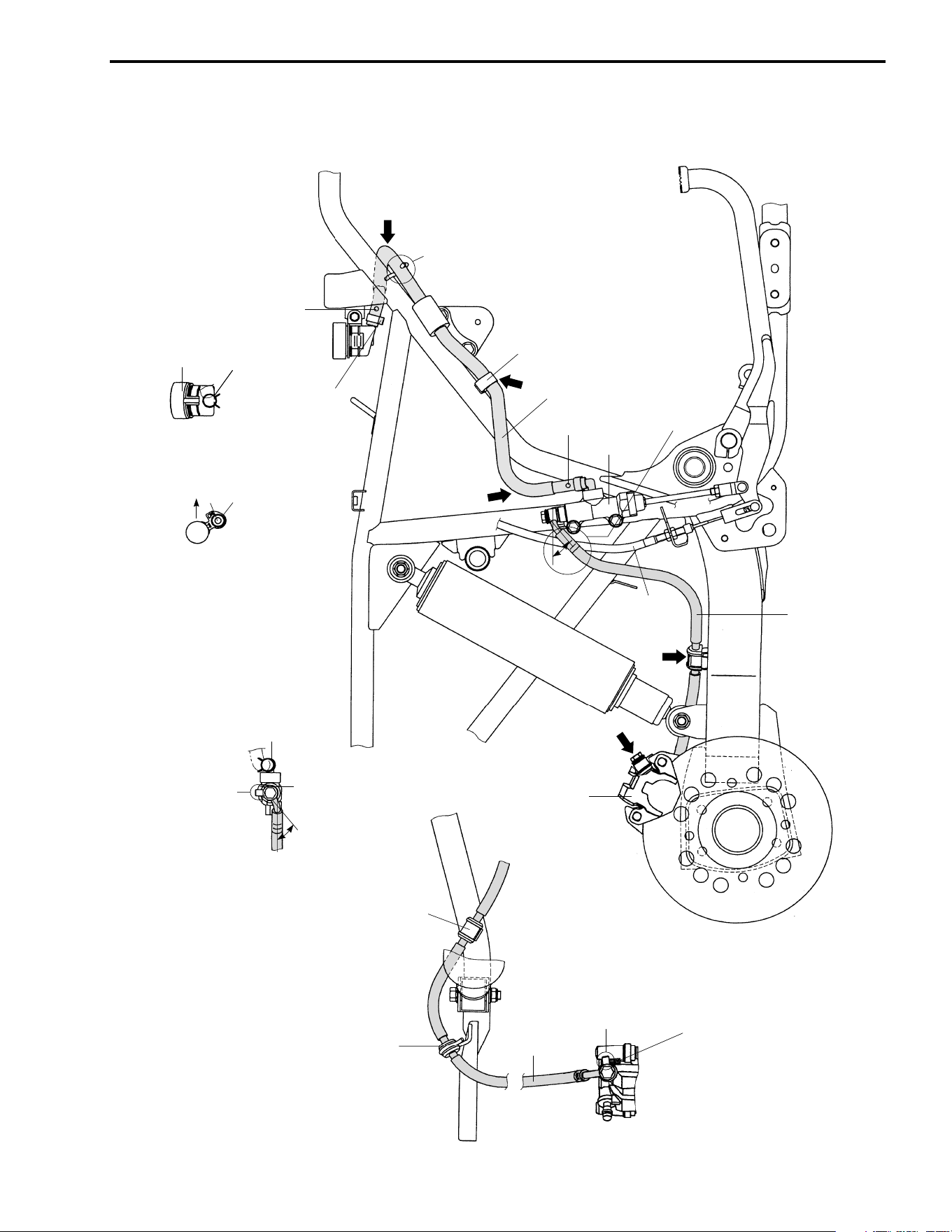
SERVICING INFORMATION 9-21
REAR BRAKE HOSE ROUTING
35˚
Clip
Stopper
VIEW C
VIEW E
VIEW D
VIEW B VIEW A
After touching the brake hose union to the
stopper, tighten the union bolt to the specified torque.
Clamp
Brake hose
Outside
Face the white mark to the outside.
Face the tip of clip to the bottom.
A
Fix the brake hose
with the hose guide.
Clamp
Brake hose
B
Face the white mark to the outside.
Rear brake master cylinder
35˚
Pass the brake hose outside of
the brake cable.
Brake
cable
D
C
E
Brake hose
Brake caliper
Brake hose
Fix the brake hose with the clamp.
Fix the brake hose with the hose guide.
After touching the brake union
to the stopper, tighten
the union bolt to the
specified torque.
Stopper
Rear brake reservoir
Clip
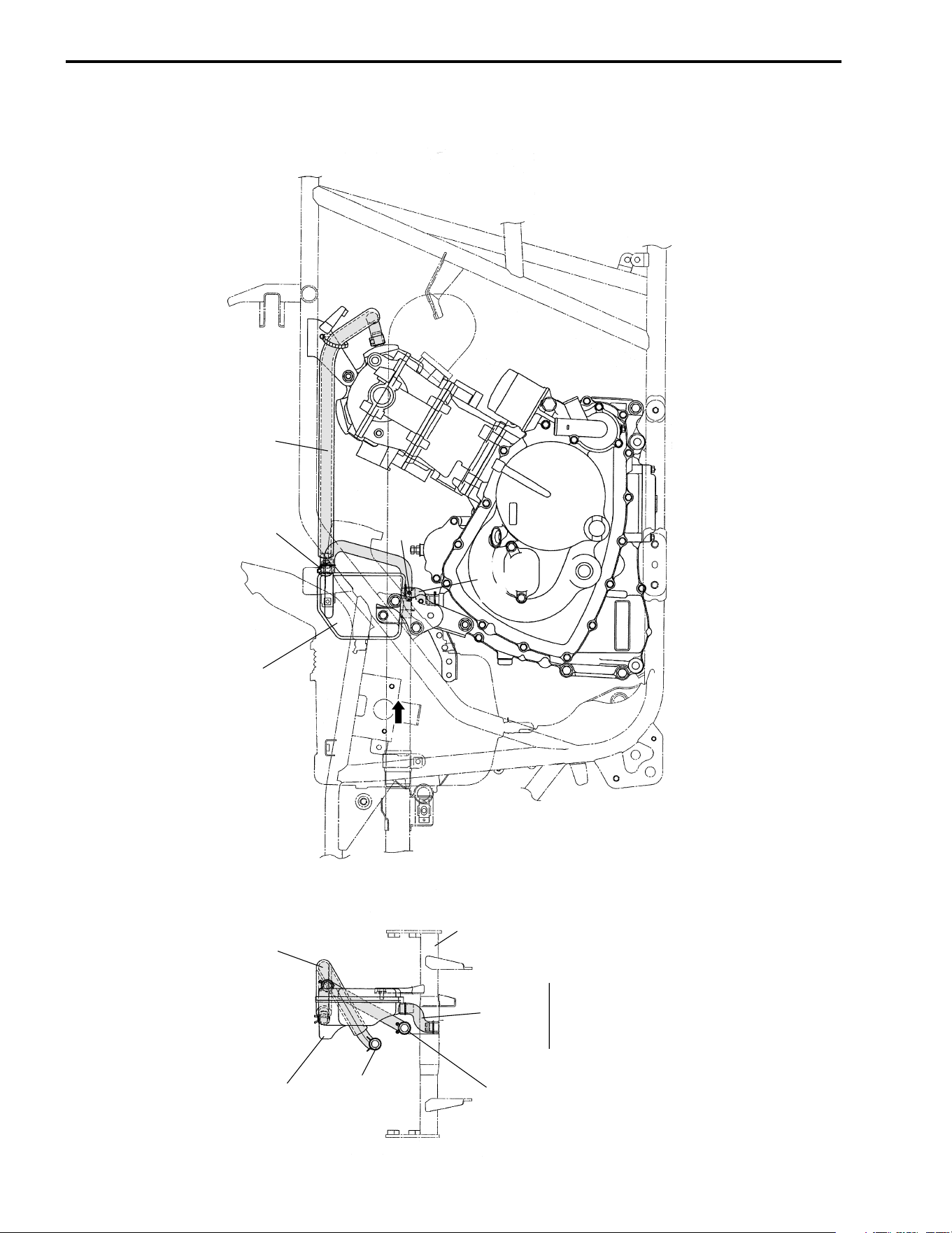
9-22 SERVICING INFORMATION
OIL RETURN TANK HOSE ROUTING
Oil return tank
Breather hose
To valve clearance
inspection cap
To air cleaner box
Breather hose
Engine mounting
bracket
VIEW A
Oil return tank
Marking
Breather hose
Marking
Breather
hose
A
SERVICING INFORMATION 9-23
SPECIAL TOOLS
09900-00410
Hexagon wrench set
09900-06106
Snap ring pliers
09900-06107
Snap ring pliers
09900-06108
Snap ring pliers
09900-09004
Impact driver set
09900-18710
Hexagon socket
(12 mm)
09900-20101
Vernier calipers
09900-20202
Micrometer
(1/100 mm,
25–50 mm)
09900-20204
Micrometer
(1/100 mm,
75–100 mm)
09900-20205
Micrometer
(1/1000 mm,
0–25 mm)
09900-20511
Cylinder gauge rod
(88 mm)
09900-20508
Cylinder gauge set
(1/100 mm,
40–80 mm)
09900-20602
Dial gauge
(1/1000 mm)
09900-20605
Dial calipers
(1/100 mm,
10–34 mm)
09900-20607
Dial gauge
(1/100 mm)
09900-20701
Magnetic stand
09900-20803
Tickness gauge
09900-20805
Tire depth gauge
09900-21203
Surface plate
09900-21304
V-block set
(100 mm)
09900-22302
Plastigauge
9-24 SERVICING INFORMATION
09900-22403
Small bore gauge
(18–35 mm)
09900-25008
Multi circuit tester
set
09900-26006
Tachometer
09910-32812
Crankshaft installer
09913-50121
Oil seal remover
09913-70210
Bearing installer set
09915-40610
Oil filter wrench
09915-64512
Compression gauge
set
09915-63310
Adaptor
09915-74511
Oil pressure gauge
09916-10911
Valve lapper set
09916-14510
Valve lifter
09916-14910
Valve lifter attach-
ment
09916-21111
09916-24900
Valve seat cutter set
09916-24311
Solid pilot
(N-100-5.0)
09916-22410
Solid pilot
(N-140-5.0)
09916-24935
Valve stem cutter
(N-608)
09916-34542
Reamer handle
09916-34570
Valve guide reamer
(5.0 mm)
09916-34580
Valve guide reamer
(10.8 mm)
09916-44310
Valve guide
remover/installer
09916-53730
Valve guide installer
09916-57340
Valve guide installer
attachnent
09916-84511
Tweezers
09917-14920
Valve adjuster driver
09917-23711
Ring nut socket
wrench
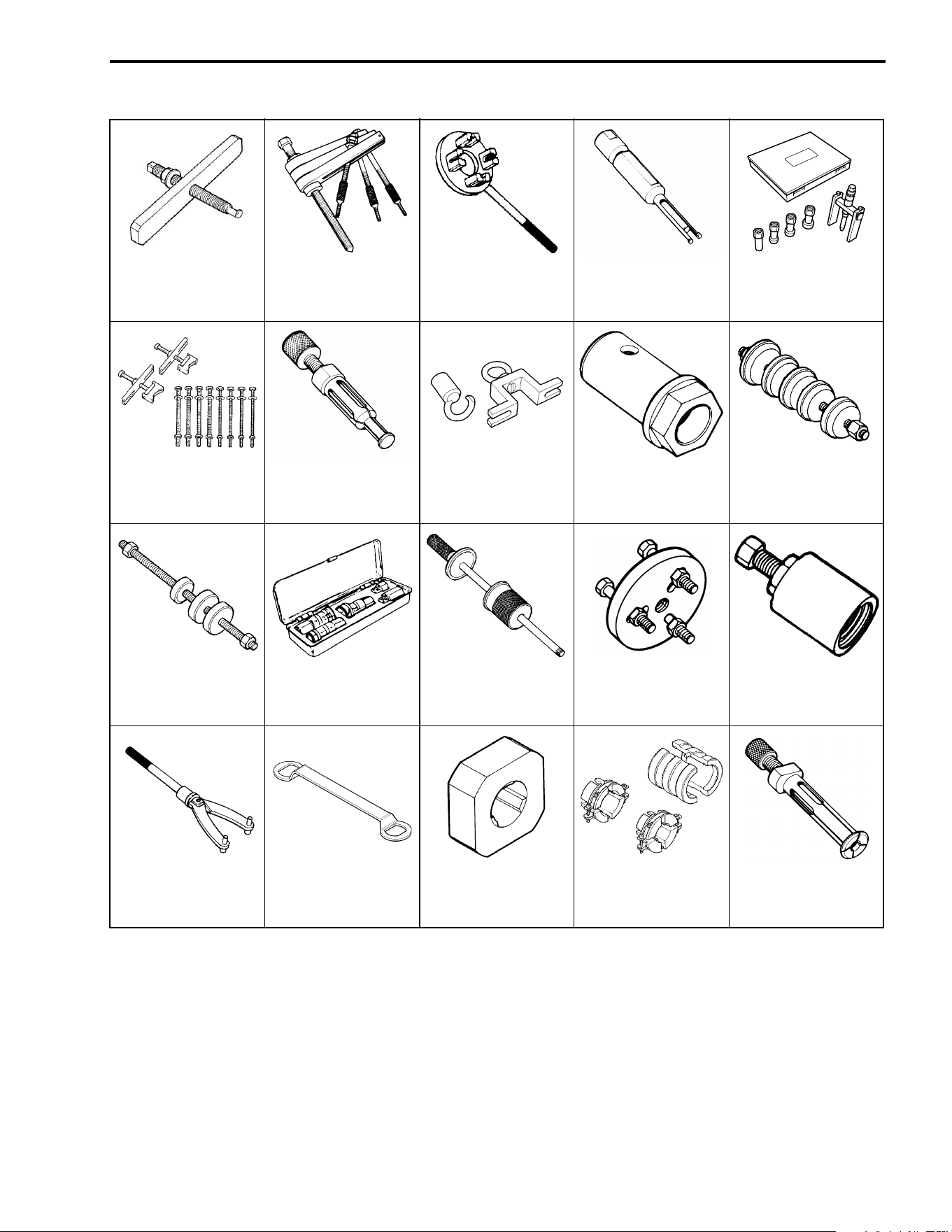
SERVICING INFORMATION 9-25
NOTE:
When ordering a special tool, please confirm whether it is available or not.
09917-50410
Bearing remover
09920-13120
Crankcase separat-
ing tool
09920-53730
Clutch sleeve hub
holder
09921-20210
Bearing remover
09921-20240
Bearing remover set
09921-21910
Bearing holder
09923-74510
Bearing remover
09924-21940
Wheel hub remover
09924-41830
Bearing locknut
wernch
09924-84510
Bearing installer set
09924-84521
Bearing installer set
09930-10121
Spark plug wrench
set
09930-30104
Sliding hammer
09930-30190
Rotor remover
attachment
09930-30721
Rotor remover
09930-40113
Rotor holder
09930-44541
Rotor holder
09930-73150
Output shaft holder
09940-52861
Front fork oil seal
installer
09941-64511
Bearing remover

9-26 SERVICING INFORMATION
TIGHTENING TORQUE
ENGINE
ITEM N·m kgf-m lb-ft
Cylinder head cover bolt 10 1.0 7.0
Camshaft sprocket bolt 15 1.5 11.0
Cylinder head bolt 38 3.8 27.5
Cylinder head nut
6 mm 10 1.0 7.0
8 mm 25 2.5 18.0
Cylinder base nut 10 1.0 7.0
Cam chain tensioner bolt 13 1.3 9.5
Cam chain tension adjuster mounting bolt 10 1.0 7.0
Cam chain tension adjuster spring holder bolt 8 0.8 6.0
Spark plug 11 1.1 8.0
Valve clearance adjuster locknut 10 1.0 7.0
Rocker arm shaft set bolt 28 2.8 20.0
Crankcase bolt
6 mm 11 1.1 8.0
8 mm 22 2.2 16.0
Neutral switch bolt 6.5 0.65 4.5
T.D.C. plug 23 2.3 16.5
Clutch shoe nut 130 13.0 94.0
Generator rotor nut 160 16.0 115.5
Starter clutch bolt 26 2.6 19.0
Oil pump drive gear bolt 80 8.0 58.0
Gearshift cam stopper 10 1.0 7.0
Exhaust pipe nut 23 2.3 16.5
Muffler mounting bolt 23 2.3 16.5
Muffler connecting bolt 23 2.3 16.5
Engine oil drain plug 23 2.3 16.5
Drive/driven bevel gear nut 100 10.0 72.5
Engine mounting nut
8 mm 40 4.0 29.0
10 mm 55 5.5 40.0
Engine mounting bracket bolt 26 2.6 19.0
Front drive (differential) gear case mounting bolt 45 4.5 32.5
Front/rear output shaft nut 100 10.0 72.5
Oil filter union 15 1.5 11.0
Reverse cam stopper 23 2.3 16.5
Clutch sleeve hub nut 100 10.0 72.5
SERVICING INFORMATION 9-27
DIFFERENTIAL
CHASSIS
ITEM N·m kgf-m lb-ft
Front drive (differential) gear oil drain plug 32 3.2 23.0
Front drive (differential) gear oil filler plug 35 3.5 25.5
Front drive (differential) gear case mounting nut 45 4.5 32.5
Front drive (differential) gear case bolt 23 2.3 16.5
Front propeller shaft flange coupling bolt 45 4.5 32.5
Rear drive shaft housing nut 23 2.3 16.5
Rear propeller shaft flange coupling bolt 30 3.0 21.5
Rear drive gear case bolt 23 2.3 16.5
Rear drive gear oil filler plug 33 3.3 24.0
Rear drive gear oil drain plug 33 3.3 24.0
ITEM N·m kgf-m lb-ft
Handlebar clamp bolt 23 2.3 16.5
Steering shaft holder bolt 23 2.3 16.5
Steering shaft nut 49 4.9 35.5
Steering knuckle pinch bolt 50 5.0 36.0
Tie rod end nut 60 6.0 43.5
Tie rod locknut 29 2.9 21.0
Front shock absorber mounting bolt (upper) 55 5.5 40.0
Front shock absorber mounting nut (lower) 60 6.0 43.5
Wishbone arm pivot nut 65 6.5 47.0
Hub nut (front and rear) 110 11.0 79.5
Wheel set nut (front and rear) 50 5.0 36.0
Brake master cylinder mounting bolt (front and rear) 10 1.0 7.0
Brake hose union bolt 23 2.3 16.5
Front brake pipe nut 16 1.6 11.5
Brake air bleeder valve (front and rear) 7.5 0.75 5.5
Brake disc bolt (front and rear) 23 2.3 16.5
Brake caliper mounting bolt (front) 26 2.6 19.0
Brake caliper mounting bolt (rear) 32 3.2 23.0
Brake pad mounting bolt (front) 18 1.8 13.0
Footrest bolt
8 mm 26 2.6 19.0
10 mm 55 5.5 40.0
Rear master cylinder rod locknut 18 1.8 13.0
Rear brake pedal bolt 26 2.6 19.0
Rear shock absorber mounting nut (upper) 35 3.5 25.5
nut (lower) 60 6.0 43.5
Rear swingarm pivot bolt (left) 100 10.0 72.5
bolt (right) 9.5 0.95 7.0
locknut (right) 100 10.0 72.5
9-28 SERVICING INFORMATION
TIGHTENING TORQUE CHART
For other nuts and bolts not listed in the preceding page, refer to this chart:
Bolt Diameter
A
AA
A (mm)
Conventional or “4” marked bolt “7” marked bolt
N·m kgf-m lb-ft N·m kgf-m lb-ft
4 1.5 0.15 1.0 2.3 0.23 1.5
5 3 0.3 2.0 4.5 0.45 3.0
6 5.5 0.55 4.0 10 1.0 7.0
8 13 1.3 9.5 23 2.3 16.5
10 29 2.9 21.0 50 5.0 36.0
12 45 4.5 32.5 85 8.5 61.5
14 65 6.5 47.0 135 13.5 97.5
16 105 10.5 76.0 210 21.0 152.0
18 160 16.0 115.5 240 24.0 173.5
Conventional bolt
“4” marked bolt
“7” marked bolt
A

SERVICING INFORMATION 9-29
SERVICE DATA
VALVE + GUIDE
Unit: mm (in)
ITEM STANDARD LIMIT
Valve diam.
IN.
30.6
(1.20)
—
EX.
27.0
(1.06)
—
Valve clearance (when cold)
IN.
0.05 – 0.10
(0.002 – 0.004)
—
EX.
0.17 – 0.22
(0.007 – 0.009)
—
Valve guide to valve stem
clearance
IN.
0.010 – 0.037
(0.0004 – 0.0015)
—
EX.
0.030 – 0.057
(0.0012 – 0.0024)
—
Valve stem deflection
IN. & EX. —
0.35
(0.014)
Valve guide I.D.
IN. & EX.
5.000 – 5.012
(0.1969 – 0.1973)
—
Valve stem O.D.
IN.
4.975 – 4.990
(0.1959 – 0.1965)
—
EX.
4.955 – 4.970
(0.1951 – 0.1957)
—
Valve stem runout
IN. & EX. —
0.05
(0.002)
Valve head thickness
IN. & EX. —
0.5
(0.02)
Valve stem end length
IN. & EX. —
1.7
(0.07)
Valve seat width
IN. & EX.
0.9 – 1.1
(0.035 – 0.043)
—
Valve head radial runout
IN. & EX. —
0.03
(0.001)
Valve spring free length
(IN. & EX.)
—
38.8
(1.53)
Valve spring tension (IN. & EX.) 18.2 – 21.0 kgf
(40.1 – 46.3 lbs)
at length 31.5 mm (1.24 in)
—
9-30 SERVICING INFORMATION
CAMSHAFT + CYLINDER HEAD
Unit: mm (in)
CYLINDER + PISTON + PISTON RING
Unit: mm (in)
ITEM STANDARD LIMIT
Cam height
IN.
33.430 – 33.484
(1.3161 – 1.3183)
33.130
(1.3043)
EX.
33.500 – 33.554
(1.3189 – 1.3210)
33.200
(1.3071)
Camshaft journal oil clearance Right &
Center
0.032 – 0.066
(0.0013 – 0.0026)
0.150
(0.0059)
Left
0.028 – 0.059
(0.0011 – 0.0023)
0.150
(0.0059)
Camshaft journal holder I.D. Right &
Center
22.012 – 22.025
(0.8666 – 0.8671)
—
Left
17.512 – 17.525
(0.6894 – 0.6900)
—
Camshaft journal O.D. Right &
Center
21.959 – 21.980
(0.8645 – 0.8654)
—
Left
17.466 – 17.484
(0.6876 – 0.6883)
—
Camshaft runout
—
0.10
(0.004)
Rocker arm I.D.
IN. & EX.
12.000 – 12.018
(0.4724 – 0.4731)
—
Rocker arm shaft O.D.
IN. & EX.
11.973 – 11.984
(0.4714 – 0.4718)
—
Cylinder head distortion
—
0.05
(0.002)
Cylinder head cover distortion
—
0.05
(0.002)
ITEM STANDARD LIMIT
Compression pressure
(Automatic-decomp. actuated) Approx. 1 000 kPa (10.0 kgf/cm
2
, 142 psi)
800 kPa
(8.0 kgf/cm
2
,
114 psi)
Piston to cylinder clearance 0.030 – 0.040
(0.0012 – 0.0016)
—
Cylinder bore 87.500 – 87.515
(3.4449 – 3.4455)
Nicks or
Scratches
Piston diam. 87.465 – 87.480
(3.4435 – 3.4441)
Measure at 15 mm (0.6 in) from the skirt end.
87.380
(3.4402)
Cylinder distortion
—
0.05
(0.002)
Piston ring free end gap
1st R Approx.
11.2
(0.44)
9.0
(0.35)
2nd R Approx.
11.9
(0.47)
9.5
(0.37)
Piston ring end gap
1st
0.10 – 0.25
(0.004 – 0.010)
0.50
(0.020)
2nd
0.10 – 0.25
(0.004 – 0.010)
0.50
(0.020)
Piston ring to groove clearance
1st —
0.180
(0.0071)
2nd —
0.150
(0.0059)
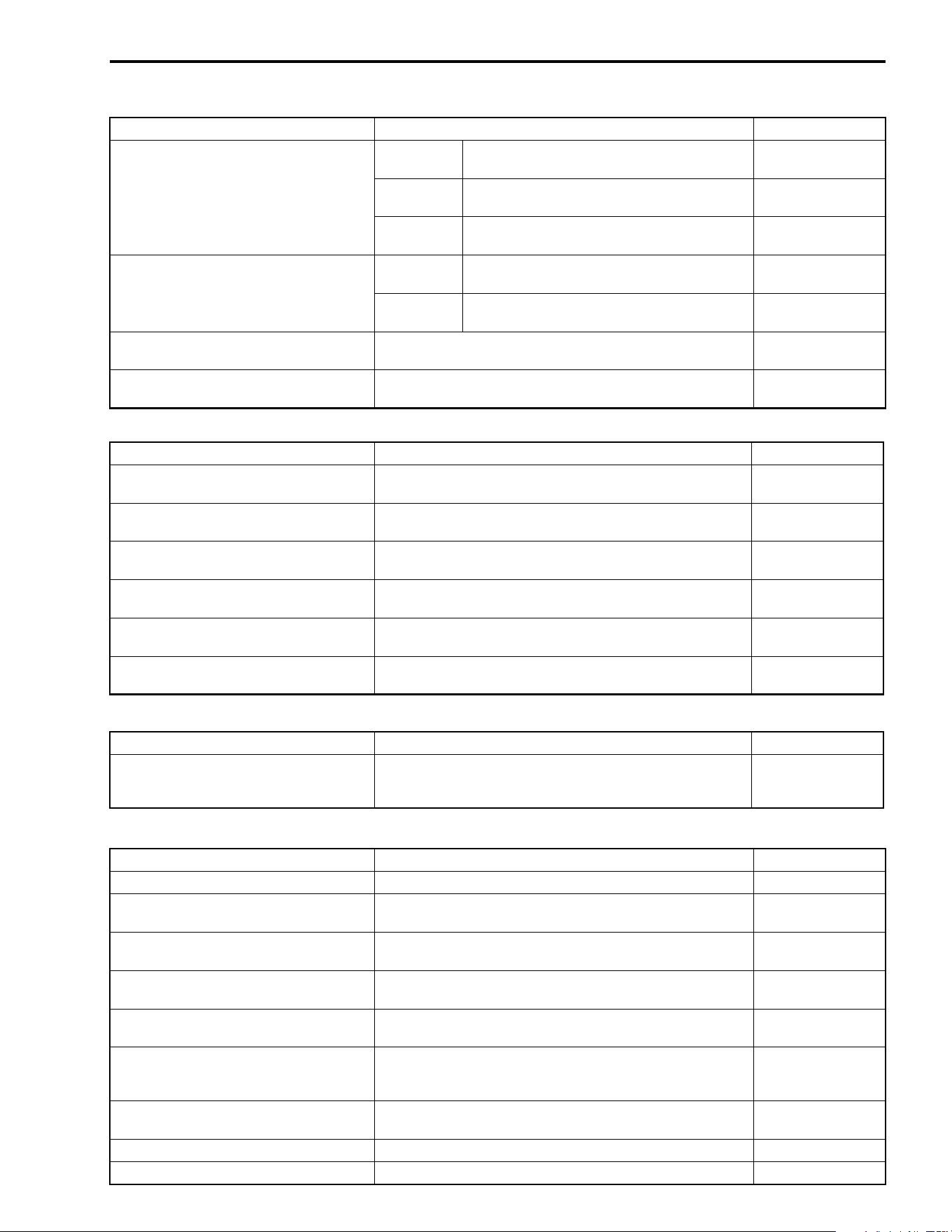
SERVICING INFORMATION 9-31
CONROD + CRANKSHAFT
Unit: mm (in)
OIL PUMP
CLUTCH
Unit: mm (in)
ITEM STANDARD LIMIT
Piston ring groove width
1st
1.01 – 1.03
(0.0398 – 0.0406)
—
2nd
1.21 – 1.23
(0.0476 – 0.0484)
—
Oil
2.51 – 2.53
(0.0988 – 0.0996)
—
Piston ring thickness
1st
0.97 – 0.99
(0.0382 – 0.0390)
—
2nd
1.17 – 1.19
(0.0461 – 0.0469)
—
Piston pin bore 23.002 – 23.008
(0.9056 – 0.9058)
23.030
(0.9067)
Piston pin O.D. 22.992 – 23.000
(0.9052 – 0.9055)
22.980
(0.9047)
ITEM STANDARD LIMIT
Conrod small end I.D. 23.006 – 23.014
(0.9057 – 0.9061)
23.040
(0.9071)
Conrod deflection
—
3.0
(0.12)
Conrod big end side clearance 0.10 – 0.65
(0.004 – 0.026)
1.0
(0.039)
Conrod big end width 24.95 – 25.00
(0.982 – 0.984)
—
Crank web to web width 70.9 – 71.1
(2.791 – 2.799)
—
Crankshaft runout
—
0.08
(0.003)
ITEM STANDARD LIMIT
Oil pressure (at 60 °C, 140 °F) Above 120 kPa (1.2 kgf/cm
2
, 17.0 psi)
Below 160 kPa (1.6 kgf/cm
2
, 23.0 psi)
at 3 000 r/min.
—
ITEM STANDARD LIMIT
Clutch release screw 1/4 – 2/4 turn back —
Drive plate thickness 2.92 – 3.08
(0.115 – 0.121)
2.62
(0.103)
Drive plate claw width
—
13.18
(0.519)
Driven plate distortion
—
0.10
(0.004)
Clutch spring free length
—
33.8
(1.33)
Clutch wheel I.D.
140.0 – 140.2
(5.512 – 5.520)
Scuffing or
scratch on
contacting surface
Clutch shoe
—
No groove at
any part
Clutch engagement r/min. 1 500 – 1 900 r/min. —
Clutch lock-up r/min. 3 400 – 4 000 r/min. —
9-32 SERVICING INFORMATION
DRIVE TRAIN
Unit: mm (in) Except ratio
SHAFT DRIVE
Unit: mm (in)
THERMOSTAT + RADIATOR + FAN + COOLANT
ITEM STANDARD LIMIT
Primary reduction ratio 2.032 (63/31) —
Secondary reduction ratio 1.133 (17/15) —
Final reduction ratio Front 3.600 (36/10) —
Rear 3.600 (36/10) —
Transfer gear ratio Low 2.419 (22/23 × 27/17 × 43/27) —
High 1.592 (43/27) —
Transmission gear ratio Low 3.090 (34/11) —
2nd 1.750 (28/16) —
3rd 1.200 (24/20) —
4th 0.875 (21/24) —
Top 0.724 (21/29) —
Reverse 2.636 (24/11 × 29/24) —
Shift fork to groove clearance 0.10 – 0.30
(0.004 – 0.012)
0.5
(0.020)
Transfer fork to groove clearance 0.10 – 0.30
(0.004 – 0.012)
0.5
(0.020)
Reverse fork to groove
clearance
0.10 – 0.30
(0.004 – 0.012)
0.5
(0.020)
Shift fork groove
width
No. 1 & No. 2
5.5 – 5.6
(0.217 – 0.220)
—
Transfer
5.5 – 5.6
(0.217 – 0.220)
—
Reverse
5.0 – 5.1
(0.197 – 0.201)
—
Shift fork thickness
No. 1 & No. 2
5.3 – 5.4
(0.209 – 0.213)
—
Transfer
5.3 – 5.4
(0.209 – 0.213)
—
Reverse
4.8 – 4.9
(0.189 – 0.193)
—
ITEM STANDARD LIMIT
Secondary drive bevel gear
backlash
0.05 – 0.15
(0.002 – 0.006)
—
Final drive bevel gear backlash 0.08 – 0.13
(0.0031 – 0.0051)
—
Front differential drive bevel gear
backlash
0.05 – 0.10
(0.0020 – 0.0040)
—
TEM STANDARD LIMIT
Thermostat valve opening
temperature
73.5 – 76.5 °C
(164 – 170 °F)
—
Thermostat valve lift Over 3 mm (0.12 in) at 90 °C (194 °F) —
Radiator cap valve opening
pressure
95 – 125 kPa (0.95 – 1.25 kgf/cm
2
, 13.5 – 17.8 psi) —
SERVICING INFORMATION 9-33
CARBURETOR
ELECTRICAL
Unit: mm (in)
ITEM STANDARD/SPECIFICATION LIMIT
Engine coolant temp. indicator light
thermo-switch operating temperature
OFF→
→→
→ON Approx. 115 °C (239 °F)
ON→
→→
→OFF Approx. 108 °C (226 °F)
Cooling fan thermo-switch
operating temperature
OFF→
→→
→ON Approx. 88 °C (190 °F)
ON→
→→
→OFF Approx. 82 °C (180 °F)
Engine coolant type
Use an anti-freeze/coolant compatible with aluminum radi-
ator, mixed with distilled water only, at the ratio of 50 : 50.
Engine coolant including
reserve
2 000 ml
(2.1/1.8 US/lmp qt)
ITEM
SPECIFICATION
E-03, 28 E-33
Carburetor type KEIHIN CVK36 ←
Bore size 36 mm ←
I.D. No. 03GF 03GG
Idle r/min. 1 300 ± 100 r/min. ←
Float height 17.0 ± 1.0 mm
(0.67 ± 0.04 in)
←
Main jet (M.J.) #128 ←
Jet needle (J.N.) NBAY ←
Needle jet (N.J.) #6 ←
Slow jet (S.J.) #35 ←
Pilot screw (P.S.) 1·3/8 turns back PRE-SET
Throttle cable play 3 – 5 mm
(0.12 – 0.20 in)
←
Choke cable play 0.5 – 1.0 mm
(0.02 – 0.04 in)
←
ITEM SPECIFICATION NOTE
Spark plug
Type
NGK: CR6E
DENSO: U20ESR-N
Gap
0.7 – 0.8
(0.028 – 0.031)
Spark performance Over 8 (0.3) at 1 atm.
Ignition coil resistance Primary 0.1 – 1.5 Ω
Terminal – Ground
Secondary 12 – 22 kΩ
Plug cap – Ground
Generator coil resistance Pick-up 150 – 300 Ω BI – G
Power
source
0.05 – 1.0 Ω Y – W
Charging 0.1 – 1.5 Ω B – B
Generator no-load voltage
(When engine is cold)
More than 60 V (AC) at 5 000 r/min.
Generator Max. output
Approx. 325 W at 5 000 r/min.
The rotation of
the generator
Regulated voltage 14.0 – 15.5 V at 5 000 r/min.
Ignition coil primary peak voltage More than 150 V
+: Bl/W,
-: W/B
Starter relay resistance 3 – 5 Ω
9-34 SERVICING INFORMATION
WATTAGE
Unit: W
BRAKE + WHEEL
Unit: mm (in)
ITEM SPECIFICATION NOTE
Battery Type designation FTH16-BS
Capacity 12 V 50.4 kC (14 Ah)/10 HR
Fuze size Main 30 A
Power source 10 A
Headlight (HI) 10 A
Headlight (LO) 10 A
Ignition 15 A
Aux 10 A
ITEM SPECIFICATION
Headlight HI 30 × 2 pcs.
LO 30 × 2 pcs.
Auxiliary light 40
Brake light/Taillight 21/5
Speedometer light LED
Reverse indicator light LED
Neutral indicator light LED
Parking indicator light LED
High beam indicator light LED
Engine coolant temp. indicator light LED
ITEM STANDARD/SPECIFICATION LIMIT
Rear brake pedal height 5 – 15
(0.2 – 0.6)
—
Brake caliper cylinder bore
Front
32.030 – 32.080
(1.2610 – 1.2630)
—
Rear
33.960 – 34.036
(1.3346 – 1.34)
—
Brake caliper piston diam.
Front
31.948 – 31.998
(1.2578 – 1.2598)
—
Rear
33.884 – 33.934
(1.3340 – 1.3360)
—
Brake fluid type DOT 4 —
Brake disc thickness
Front
3.3 – 3.7
(0.130 – 0.146)
3.0
(0.118)
Rear
3.8 – 4.2
(0.150 – 0.165)
3.5
(0.138)
Brake disc runout (Front & Rear)
—
0.30
(0.012)
Master cylinder bore
Front
14.000 – 14.043
(0.5512 – 0.5529)
—
Rear
12.700 – 12.743
(0.5000 – 0.5017)
—
Master cylinder piston diam.
Front
13.957 – 13.984
(0.5495 – 0.5506)
—
Rear
12.657 – 12.684
(0.4983 – 0.4994)
—
SERVICING INFORMATION 9-35
TIRE PRESSURE
VEHICLE LOAD CAPACITY LIMIT: 172 kg (380 lbs)
FUEL + OIL
ITEM STANDARD/SPECIFICATION LIMIT
Turning radius 3.0 m (9.8 ft)
Toe-in (with 75 kg, 165 lbs) 7 ± 4
(0.30 ± 0.16)
Chamber 0.45°
Caster 3.3°
Wheel rim size Front 12 × 6.0 AT —
Rear 12 × 7.5 AT —
Tire size Front AT25 × 8-12 ✩✩ —
Rear AT25 × 10-12 ✩✩ —
Tire type Front DUNLOP: KT121D —
Rear DUNLOP: KT405D —
Tire tread depth
Front —
4.0
(0.16)
Rear —
4.0
(0.16)
COLD INFLATION
TIRE PRESSURE
kPa kgf/cm
2
psi NOTE
FRONT 35 0.35 5.1
LOAD CAPACITY
UP TO 172 kg (380 lbs)
REAR 30 0.30 4.4
ITEM SPECIFICATION NOTE
Fuel type Use only unleaded gasoline of at least 87 pump
octane ( ) or 91 octane or higher rated by the
research method.
Gasoline containing MTBE (Methyl Tertiary Butyl
Ether), less than 10 % ethanol, or less than 5 %
methanol with appropriate cosolvents and corro-
sion inhibitor is permissible.
Fuel tank including reserve 19.0 L
(5.0/4.2 US/lmp gal)
reserve 4.2 L
(1.1/0.9 US/lmp gal)
Engine oil type SAE 10W-40, API SF or SG
Engine oil capacity
Change
3 400 ml
(3.6/3.0 US/lmp qt)
Filter change
3 600 ml
(3.8/3.2 US/lmp qt)
Overhaul
4 000 ml
(4.2/3.5 US/lmp qt)
Differential gear and final bevel
gear oil type
Hypoid gear oil SAE #90,
API grade GL-5
Differential gear oil capacity 270 – 370 ml
(9.1 – 12.5/9.5 – 13.0 US/lmp oz)
Final bevel gear oil capacity 250 – 350 ml
(8.5 – 10.1/8.8 – 10.6 US/lmp oz)
2
R + M
Prepared by
August, 2002
Part No. 99500-44050-01E
Printed in Japan
384
Printed in Japan
K3
No. 1405 99500-44050-01E LT-F500F S/M August, 09, 2002
No. 1405 99500-44050-01E LT-F500F S/M August, 09, 2002