MADE IN CHINA
Distributed by Jasco Products Company LLC, 10 E. Memorial
Rd., Oklahoma City, OK 73114.
This Jasco product comes with a limited-lifetime warranty.
Visit www.byjasco.com for warranty details.
Questions? Contact our U.S.-based Consumer Care at
1-800-654-8483 between 7AM—8PM CST.
HECHO EN CHINA
Distribuido por Jasco Products Company LLC, 10 E Memorial Rd.,
Oklahoma City, Oklahoma 73114.
Este producto de Jasco tiene una garantía de por vida limitada. Visite
www.byjasco.com para conocer los detalles de la garantía.
¿Preguntas? Comuníquese al 1-800-654-8483 entre las 7AM y las 8PM
CST (hora central estándar).
44420
44975
44974
6/12/19 V1
IMPORTANT SAFETY
INSTRUCTIONS
This portable light has a polarized plug (one blade is
wider than the other) to reduce the risk of electric shock.
This plug fits in a polarized outlet only one way. If the
plug does not fit fully in the outlet, reverse the plug. If it
still does not fit, contact a qualified electrician. Never use
with on extension cord unless plug can be fully inserted.
Do not alter the plug. Read entire installation instructions
before you begin.
SAVE THESE INSTRUCTIONS FOR POSSIBLE
FUTURE USE.
INSTALLATION INSTRUCTIONS:
Carefully plan out your installation prior to securing your lights to the mounting surface or drilling any
holes for recessed mounting. Be sure to consider distances to make sure pucks will interconnect via
linking cords and that the 5ft. power cord will reach the nearest electrical outlet.
For kitchen installations, the recommended mounting for LED puck
lights is near the front lip of your kitchen under cabinets as shown in
Figure 1. This provides the best light distribution across a countertop.
1. DO NOT ATTEMPT TO INSTALL FIXTURE WHILE PLUGGED IN.
2. Select a suitable dry mounting location (indoor only). Make
sure mounting surface is capable of supporting the LED puck
light.
3. Locate positions where the puck should be mounted (keep in
mind length of power cord and linking cords).
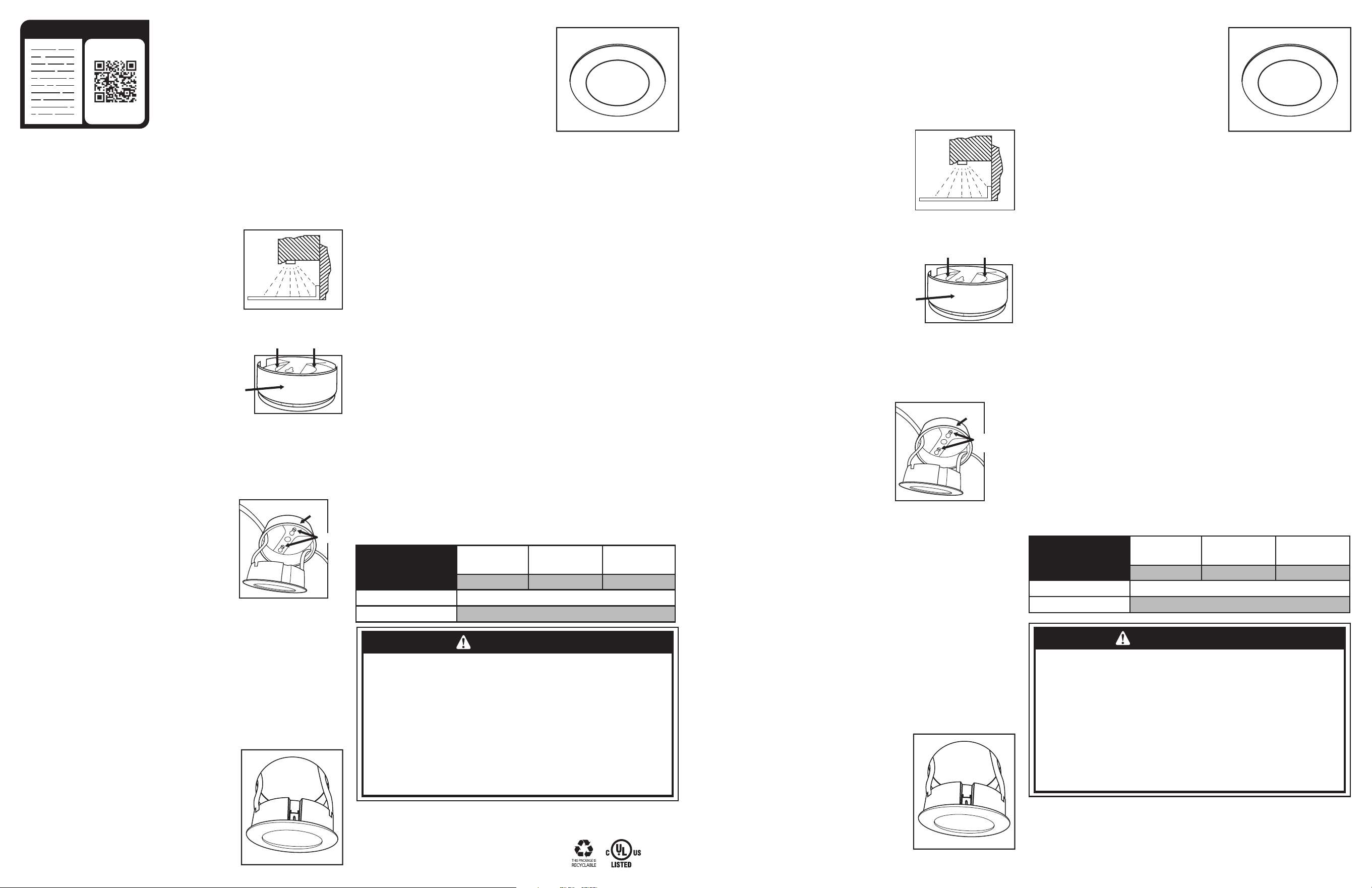
4. Remove trim ring by firmly grasping ring and then firmly pushing on back side of puck as
shown in Figure 2.
5. For recessed mount applications, skip to Step 17. For
surface mount applications, continue with Steps 6-16.
6. Using the trim ring as a template, mark the locations of
the mounting holes on the mounting surface. Be sure to
orient the trim ring openings for routing linking cords.
7. Pre-drill holes in the mounting surface with a 1/16"
(1.5mm) drill bit for soft woods and 3/32” (2.4mm) drill
bit for hard woods.
8. Secure the trim ring with the mounting screws (included), keeping the power cables
threaded through trim ring openings.
9. Secure the puck in the trim ring by firmly pushing the puck into the trim ring while feeding
the power cords through the trim ring openings until the puck snaps into place. See Figure 3.
10. The power cord has a molded plug on one end with an in-line switch and a link connector
at the other end. The link connector plugs into the LED puck
light link connector. The two other cords provided are linking
cords with link connectors on both ends. These are used to
connect the initial LED puck to the next puck in a chain. Link
adjacent pucks only.
11. Attach the power cord link connector to the LED puck light
link connector of the initial puck installed closest to the outlet.
12. Install the next puck close enough to the initial puck for the
12" link cord to reach the additional LED puck light following
Steps 1-9 of the mounting instructions.
13. Once installed, attach the linking cord between the initial LED
puck (previously installed) and the new LED puck.
14. Repeat steps 12-13 for each additional LED puck in a chain.
15. When adding an additional LED puck to an existing, compatible, LED puck installation, the
power cord (with the power plug) is not needed. Only the first LED puck in the chain needs
to be connected to power with the power cord. Connect a maximum of 40 pucks together.
16. Plug power cord power plug into a 120VAC 60Hz outlet. Surface mount installation is
complete.
17. For Recessed Mount Applications: Discard the trim ring. It will not be needed in recessed
mount applications.
18. Mark the locations of the puck lights on the mounting surface with a pencil. Before you drill,
be sure to consider distances to make sure pucks will interconnect via linking cables and that
the power cord will reach the receptacle.
19. Using a power drill and 2 1/2” hole saw, drill mounting holes for the LED puck lights
20. Route cords of LED puck lights through the holes (see Figure
4) and press puck light into mounting hole until fully seated
(see Figure 5).
21. Connect the LED puck lights together with the 12” linking
cords between pucks.
22. Attach the power cord link connector to the LED puck light
link connector of the puck installed closest to the outlet.
23. Plug power cord power plug into a 120VAC 60Hz outlet.
Recess mount installation is complete.
DIMMABLE FUNCTIONALITY:
1. For use of dimming function, please purchase the GE-
branded under cabinet fixture junction box, part number
INSTRUCCIONES DE SEGURIDAD IMPORTANTES
Esta luz portátil tiene un enchufe polarizado (es decir, una clavija del enchufe es más ancha que la otra) para
reducir el riesgo de descarga eléctrica. Este enchufe encaja solo de una manera en un tomacorriente polarizado.
Si el enchufe no encaja por completo en el tomacorriente, inviértalo. Si aun así no encaja, llame a un electricista
profesional. Nunca lo utilice con un cable alargador, a menos que el enchufe pueda insertarse por completo. No
modifique el enchufe. Antes de comenzar, lea todo el procedimiento de instalación.
GUARDE ESTAS INSTRUCCIONES PARA CUALQUIER CONSULTA FUTURA.
INSTRUCCIONES DE INSTALACIÓN:
Planifique detenidamente la instalación antes de fijar las luces a la superficie
de montaje o de perforar orificios en el caso de una instalación empotrada.
Tenga en cuenta las distancias para asegurarse de que los discos puedan
interconectarse mediante cables de conexión y de que el cable de alimentación
eléctrica de 5pies (1,52m) llegue hasta el tomacorriente más cercano.
Para instalaciones en cocinas, se recomienda que la superficie donde se
colocarán los discos de iluminación LED esté cerca del borde frontal de los
gabinetes, como se muestra en la Figura1. De esta manera, logrará la mejor
distribución de luz en toda la encimera.
1. NO INTENTE INSTALAR EL APARATO SI ESTÁ ENCHUFADO.
2. Seleccione un lugar seco adecuado para la instalación (solo
para uso en interiores). Asegúrese de que la superficie en la
que desea instalar el disco de iluminación LED podrá soportar
el peso.
3. Ubique las posiciones donde se instalará el disco (tenga en
cuenta la longitud delcable de alimentación eléctrica y de los
cables de conexión).
4. Para quitar el anillo de reborde, con firmeza, tome el aro y haga
presión en la parte posterior del disco, como se muestra en la
Figura2.
5. Para las aplicaciones que requieren montaje empotrado, siga con
el paso17. Para las aplicaciones que requieren montaje superficial, continúe con los pasos6 a16.
6. Usando el anillo de reborde como plantilla, marque las ubicaciones de los orificios de montaje en la superficie
de instalación. Asegúrese de orientar las aberturas del anillo
de reborde para pasar los cables de conexión.
7. Perfore los orificios en la superficie de instalación con una broca
de1/16" (1,5mm) para maderas blandas y con una broca de3/32"
(2,4mm) paramaderas duras.
8. Fije el anillo de reborde con los tornillos de montaje (incluidos);
los cables de alimentación eléctrica deben quedar pasados por las
aberturas del anillo de reborde.
9. Para asegurar el disco en el anillo de reborde, presione con firmeza el
anillo de reborde mientras pasa los cables de alimentación eléctrica a
través de las aberturas del anillo de reborde hasta que el disco encaje
en el lugar. Ver la Figura3.
10. El cable de alimentación eléctrica tiene un enchufe moldeado en
un extremo, con un interruptor en línea y un conector en el otro
extremo. El conector se enchufa en el conector del disco de iluminación LED. Los otros dos cables provistos
son de conexión, con conectores en ambos extremos. Estos cables se utilizan para conectar en cadena el disco
de iluminación LED inicial con el siguiente. Solo conecte discos adyacentes.
11. Conecte el conector del cable de alimentación eléctrica al conector del disco de iluminación LED inicial más
cercano al tomacorriente.
12. Instale el siguiente disco lo suficientemente cerca del disco inicial para que el cable de conexión de18"
(457mm) llegue hasta el disco de iluminación LED adicional; para ello, siga los pasos1 a7 de las instrucciones
de instalación.
13. Una vez instalado, conecte el cable de conexión entre el disco de iluminación LED inicial (previamente
instalado) y el nuevo.
14. Repita los pasos12 y 13 para cada disco de iluminación LED adicional instalado en cadena.
15. Cuando agregue otro disco a una instalación existente de discos de iluminación LED compatibles, no es
necesario tener un cable de alimentación (con enchufe de alimentación). Solo el primer disco de iluminación
LED de la cadena debe estar conectado al suministro eléctrico con el cable de alimentación. Conecte hasta
40discos juntos, como máximo.
16. Inserte el enchufe de alimentación en un tomacorriente de 120VCA 60HZ. Lainstalación con montaje
superficial está completa.
17. Para las aplicaciones con montaje empotrado, descarte el anillo de reborde. No es necesario para las
aplicaciones que requieren montaje empotrado.
18. Marque las ubicaciones de los discos de iluminación en la superficie de instalación, con un lápiz. Antes de
perforar los orificios, tenga en cuenta las distancias para asegurarse de
que los discos puedan interconectarse mediante cables de conexión y de
que el cable de alimentación eléctrica llegue hasta el tomacorriente.
19. Con un taladro eléctrico y una sierra perforadora de 2" (51mm), perfore
los orificios de montaje para los discos de iluminación LED.
20. Pase los cables de los discos de iluminación LED a través de los orificios
(ver la Figura4) y presione el disco de iluminación LED en el orificio de
montaje hasta que quede totalmente apoyado (ver la Figura5).
21. Conecte los discos de iluminación LED juntos con los cables de conexión
de 18" (457mm) entre los discos.
22. Conecte el conector del cable de alimentación eléctrica al conector del
disco de iluminación LED más cercano al tomacorriente.
23. Inserte el enchufe de alimentación en un tomacorriente de 120VCA
60HZ. La instalación del montaje empotrado está completa.
39971, and follow installation instructions to hardwire
your LED pucks.
2. Linking cords can be purchased on Amazon, part nu-
mber 42283 (12in), 42284 (18in), 42285 (36in), 42286
(60in), 42287 (48in), 42289 (120in), 42290 (24in)
3. Select a compatible LED dimmer.
4. Follow dimmer setup instructions for optimal perfor-
mance.
5. Compatible with the following In-wall Dimmers GE
Z-Wave Plus 14295. Wi-Fi 40794
Legrand: WSCL450TCCCV4, RHCL453PTCCCV6
WSCL453PTCCCV4
Lutron: LECL-153PH. MACL-153MLH
Leviton: CD-R61-06674-12A, R01-DSL06-1TW. CD-R00-RNL06. CD-R62-06674-12A. CD-C22-
06672-12A
CLEANING INSTRUCTIONS
Your fixture is made from quality materials that will last for many years with minimum care. When
cleaning, make sure you have unplugged your fixture and allowed sucient time for the unit to cool to
room temperature. You should clean the housing and lens using only a soft, dry cloth. Do not use any
liquid or harsh abrasives to clean LED puck lights.
FUNCIONALIDAD ATENUABLE:
1. Para usar la función de atenuación, compre la caja de conexiones
para aparatos de instalación bajo gabinete marcaGE,
piezanúmero39971 y siga las instrucciones de instalación para
conectar los discos de iluminación LED.
2. Los cables de conexión se pueden comprar en Amazon, número
de pieza 42283 (12 pulgadas), 42284 (18 pulgadas), 42285 (36
pulgadas), 42286 (60 pulgadas), 42287 (48 pulgadas), 42289 (120
pulgadas), 42290 (24 pulgadas)
3. Seleccione un compatible dimmer LED.
4. Siga las instrucciones de configuración del dimmer para obtener
un rendimiento óptimo.
5. Lista de dimmers de pared compatibles. GE Z-Wave Plus 14295. Wi-Fi 40794
Legrand: WSCL450TCCCV4, RHCL453PTCCCV6 WSCL453PTCCCV4
Lutron: LECL-153PH. MACL-153MLH
Leviton: CD-R61-06674-12A, R01-DSL06-1TW. CD-R00-RNL06. CD-R62-06674-12A. CD-C22-06672-12A
INSTRUCCIONES DE LIMPIEZA
Este aparato está fabricado con materiales de la más alta calidad que tendrán una extensa
vida útil si se respetan unos cuidados mínimos. Al realizar la limpieza, asegúrese de haber
desenchufado el aparato y de haber dejado pasar un tiempo suficiente para que la unidad se
enfríe a temperatura ambiente. Para limpiar la carcasa y el lente, solo utilice un paño suave y
seco. No use ningún líquido ni sustancia abrasiva para limpiar los discos de iluminación LED.
ADVERTENCIA
WARNING
RISK OF ELECTRICAL SHOCK
• DISCONNECT ALL POWER BEFORE
INSTALLING.
• DO NOT USE IN WET LOCATIONS.
• USE INDOORS ONLY.
• USE ONLY INSULATED STAPLES OR PLASTIC
TIES TO SECURE THE CORDS.
• ROUTE AND SECURE THE CORDS SO THAT
THEY WILL NOT BE PINCHED OR DAMAGED.
• THIS PRODUCT CONTAINS NO SERVICEABLE
PARTS. LEDS ARE NON-REPLACEABLE.
• WIRE RUNS INSIDE WALLS MUST BE
INSTALLED IN ACCORDANCE WITH
NATIONAL AND LOCAL ELECTRICAL CODES.
IF YOU ARE UNCLEAR AS TO HOW TO
INSTALL AND WIRE THIS DEVICE, CONTACT
A QUALIFIED ELECTRICIAN.
• LED LIGHT OUTPUT IS STRONG ENOUGH
TO INJURE HUMAN EYES. DO NOT LOOK
DIRECTLY AT LEDS WITH UNPROTECTED
EYES FOR MORE THAN A FEW SECONDS.
RISK OF FIRE
• NOT INTENDED FOR ILLUMINATION OF
AQUARIUMS.
• NOT INTENDED FOR USE ABOVE STOVES,
COOK TOPS, SINKS OR HEAT-PRODUCING
APPLIANCES SUCH AS COFFEE MAKERS,
TOASTERS OR TOASTER OVENS.
• DO NOT ALLOW COMBUSTIBLE MATERIALS
TO COME IN CONTACT WITH RECESSED
MOUNTED PUCKS.
RIESGO DE DESCARGA ELÉCTRICA
• DISCONNECT ALL POWER BEFORE
INSTALLING.
• DO NOT USE IN WET LOCATIONS.
• USE INDOORS ONLY.
• USE ONLY INSULATED STAPLES OR PLASTIC
TIES TO SECURE THE CORDS.
• ROUTE AND SECURE THE CORDS SO THAT
THEY WILL NOT BE PINCHED OR DAMAGED.
• THIS PRODUCT CONTAINS NO SERVICEABLE
PARTS. LEDS ARE NON-REPLACEABLE.
• WIRE RUNS INSIDE WALLS MUST BE
INSTALLED IN ACCORDANCE WITH
NATIONAL AND LOCAL ELECTRICAL CODES.
IF YOU ARE UNCLEAR AS TO HOW TO
INSTALL AND WIRE THIS DEVICE, CONTACT
A QUALIFIED ELECTRICIAN.
• LED LIGHT OUTPUT IS STRONG ENOUGH
TO INJURE HUMAN EYES. DO NOT LOOK
DIRECTLY AT LEDS WITH UNPROTECTED
EYES FOR MORE THAN A FEW SECONDS.
RISK OF FIRE
• NOT INTENDED FOR ILLUMINATION OF
AQUARIUMS.
• NOT INTENDED FOR USE ABOVE STOVES,
COOK TOPS, SINKS OR HEAT-PRODUCING
APPLIANCES SUCH AS COFFEE MAKERS,
TOASTERS OR TOASTER OVENS.
• DO NOT ALLOW COMBUSTIBLE MATERIALS
TO COME IN CONTACT WITH RECESSED
MOUNTED PUCKS.
READ IT OR WATCH IT
Read instructions or watch easy-
to-follow video. Scan QR code or
visit http://bit.ly/2ICesKW
Figure 3
Trim Ring
Mounting
screws
Figure 5 Figura 5
Figure 4
Figura 4
Figure 1
COUNTER TOP
CABINET
TRIM
Push on back of puck
Grasp Trim
Ring
Figure 2
FCC STATEMENT:
Suppliers Declaration of Conformity | Model #: 44420, 44975, 44974 | Jasco Products
Co., 10 E. Memorial Rd., Oklahoma City, OK 73114, www.byjasco.com
This device complies with Part 15 of the FCC rules. Operation is subject to the following
two conditions: (1) this device may not cause harmful interference, and (2) this device
must accept any interference received, including interference that may cause undesired
operation.
FCC NOTE: The manufacturer is not responsible for any radio or TV interference caused
by unauthorized modifications to this equipment. Such modifications could void the
user’s authority to operate the equipment.
NOTE: This equipment has been tested and found to comply with the limits for a Class B
digital device, pursuant to Part 15 of the FCC Rules. These limits are designed to provide
reasonable protection against harmful interference in a residential installation. This
equipment generates, uses and can radiate radio frequency energy and, if not installed
and used in accordance with the instructions, may cause harmful interference to radio
communications. However, there is no guarantee that interference will not occur in a
particular installation. If this equipment does cause harmful interference to radio or
television reception, which can be determined by turning the equipment off and on, the
user is encouraged to try to correct the interference by one or more of the following
measures:
— Reorient or relocate the receiving antenna.
— Increase the separation between the equipment and receiver.
— Connect the equipment into an outlet on a circuit different from that to which the
receiver is connected.
Consult the dealer or an experienced radio/TV technician for help.
FCC — U2ZZW4202
Additional linking cords sold separately at byjasco.com
DECLARACIÓN DE LA COMISIÓN FEDERAL DE
COMUNICACIONES (FCC):
Declaración de conformidad del proveedor | Modelo #: 41617 | Jasco Products Co., 10 E. Memorial Rd.,
Oklahoma City, OK 73114, www.byjasco.com
Este dispositivo cumple con las Especificaciones del apartado 15 de las normas de la FCC y con las
especificaciones de las normas radioeléctricas (RSS) del Ministerio de Industria de Canadá aplicables
a aparatos exentos de licencia. El funcionamiento está sujeto a las siguientes dos condiciones: (1)
este dispositivo no debe provocar interferencia perjudicial, y (2) este dispositivo debe aceptar toda
interferencia que reciba, incluso la que pudiera causar un funcionamiento no deseado.
NOTA DE LA FCC: El fabricante no se hace responsable de ninguna interferencia de radio o TV
ocasionada por modificaciones no autorizadas efectuadas a este equipo. Dichas modificaciones
podrían anular la autoridad del usuario para utilizar el equipo.
NOTA: Este equipo ha sido probado y cumple con los límites para aparatos digitales de Clase B, de
conformidad con el apartado 15 de las normas de la FCC. Estos límites están diseñados para proveer
protección razonable contra interferencias perjudiciales en una instalación residencial. Este
equipo genera, usa y puede irradiar energía de radiofrecuencias y, si no se instala y usa según las
instrucciones, puede provocar interferencia perjudicial a las radiocomunicaciones. No obstante, no
hay garantías de que no ocurrirá interferencia en una instalación en particular. Si este equipo provoca
interferencia perjudicial a la recepción de radio o televisión, lo que puede determinarse encendiendo
y apagando el equipo, se recomienda que el usuario intente corregir la interferencia por medio de la
implementación de una o más de las siguientes medidas:
— Reorientar o reubicar la antena receptora.
— Incrementar la separación entre el equipo y el receptor.
— Conectar el equipo a un tomacorriente de un circuito diferente del circuito al que está conectado el
receptor.
— Consultar al distribuidor o a un técnico con experiencia en radio/televisión para solicitar asistencia.
Additional linking cords sold separately. at byjasco.com
Figura 1
ENCIMERA
GABINETE
PARED
LIGHTING SPECS
44420 / 44975 / 44974
1 Puck 3 Puck 5 Puck
LUMENS WATTS
LUMENS
PER WATT
150/ 450 /750 3/ 9 / 15 50 / 50 / 50
Color Accuracy (CR)
93 / 93 / 93
Light Color
3000K / 3000K / 3000K
ESPECIFICACIONES
DE ILUMINACIÓN
44270 / 44271 / 44272
1 Disco 3 Disco 5 Disco
Lúmenes Vatio
LUMENS
POR WATT
150/ 450 /750 3/ 9 / 15 50 / 50 / 50
Exactitud del color
93 / 93 / 93
Color claro
3000K / 3000K / 3000K
Figura 2
Empuje hacia atrás el disco
Anillo de
sujeción
de agarre
Figura 3
Anillo de ajuste
Tornillos de
montaje