FUSION SERVICE REFRIGERATED MID-VOLUME DELI MERCHANDISERS > FLAT ANGLED FRONT GLASS
> CURVED FRONT GLASS > VERTICAL FRONT GLASS > REAR LIFT FRONT GLASS > REMOTE & SELF-CONT.
> FULL AND OPEN END PANELS > REFRIGERATED-TO-DRY SWITCH AT CASE REAR (OPTIONAL)
REV AB DATE: 07/07/2023
USER MANUALS\5-9410_FUSION_USER MANUAL_GMDS_GMDSES_GMDSNA_GMDSV_REF_SVC_DELI_CASE
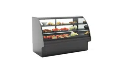
Model GMDSX4R
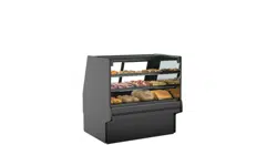
Model GMDS6R
With Rear Sliding Doors
GMDS6R.5773D No Rear Sliding
Doors / Rear Flip-Up Ledge
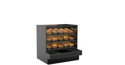
Model GMDSES6R / End Panel
Removed / Front & Rear Shelves /
Variety of Product Steps
GMDSNA4R.5773M
45° Inside Wedge
Note: See Next Page For
Various Models That This
User Manual Is Applicable.
Model GMDSX4R.5773J /
Rear Hinged Door /
Curved Front Panel
Model GMDS10R.5773F / Open Rear Section /
Curved Front Panel / Flip-Up Ledges / Scale Stand
Model GMDSES8R / End Panel Removed /
Optional Case-To-Case Glass / Front &
Rear Shelves / Variety of Product Steps
GMDSV4R / Front Vertical Glass
(Top-Hinge) /Rear Sliding Doors /
Optional Scale Stand
Model GMDSVX9R.6694
Radius Corner / Curved Front /
4 Swinging Front Doors
GMDS10R.7673 / Curved Front
Glass / Rear Sliding Doors /
Optional Rear Ledge /
Rear Storage Bins
SCC P/N
5-9410
USER
MANUAL
FUSION
CAREFULLY FOLLOW THESE INSTRUCTIONS
Structural Concepts Corp. ∙ 888 E. Porter Rd ∙ Muskegon, MI 49441 Phone: 231.798.8888 Fax: 231.798.4960 ∙ www.structuralconcepts.com
2
TABLE OF CONTENTS / LIST OF MODELS INCLUDED IN MANUAL
TABLE OF CONTENTS / LIST OF MODELS ENCOMPASSED IN MANUAL ……….………………….…..
OVERVIEW / UNIT TYPE / COMPLIANCE / WARNINGS / PRECAUTIONS / WIRING …..……….……...
INSTALLATION: REMOVAL FROM SKID, REMOVING LOWER FRONT PANELS ..……...…….…….….
INSTALLATION, CONT’D: BOLTING AND CAULKING UNITS TOGETHER ……………….………...……
INSTALLATION, CONT’D: POSITIONING & ALIGNING CASE / FRAME SUPPORT RAIL SHIMMING ..
INSTALLATION, CONT’D: FRONT GLASS ALIGNMENT & ADJUSTMENT (VIA RAIL SYSTEM) ……...
INSTALLATION, CONT’D: PROBE LEADS BOX / FIELD WIRING BOX / BALLAST (OR OPTIONAL
LED DRIVER) / ANTI-CONDENSATE AXIAL FANS .…………………………………………..….….
INSTALLATION, CONT’D: REFRIGERATION LINES / STUB-UPS / DRAINS ……..…………….….……..
INSTALLATION, CONT’D: SCALE STAND WITH OUTLETS & CAT5 / FLIP-UP LEDGE ………….……..
START-UP AND OPERATION ………………..………………………………………………………………….
MAINTENANCE FUNDAMENTALS: LED LIGHT FIXTURES / REMOVAL & REPLACEMENT...………..
MAINTENANCE FUNDAMENTALS, CONT’D: SHELF ASSEMBLIES ………………………………....……
MAINTENANCE FUNDAMENTALS, CONT’D: SHELF ASSEMBLIES / STEPS ………………….………..
MAINTENANCE FUNDAMENTALS, CONT’D: DRAIN, TXV VALVE ACCESS ………………………....….
MAINTENANCE FUNDAMENTALS, CONT’D: REAR SLIDING DOORS ……………………………….…..
MAINTENANCE FUNDAMENTALS, CONT’D: REAR LIFT FRONT GLASS ………………………………..
MAINTENANCE FUNDAMENTALS, CONT’D: REFRIGERATED TO DRY SWITCH (OPTIONAL) ……...
MAINTENANCE FUNDAMENTALS, CONT’D: CUTTING BOARD / REAR LEDGE REMOVAL ...……….
MAINTENANCE FUNDAMENTALS, CONT’D: REFRIGERATION PACKAGE LAYOUT ……………….…
MAINTENANCE FUNDAMENTALS, CONT’D: REMOTE UNIT FIELD ACCESS BOX / MISTING
SYSTEMS…………………………………………………………………………………………………...
CLEANING SCHEDULE - INTERIOR: TO BE PERFORMED BY STORE PERSONNEL .………………...
CLEANING SCHEDULE - EXTERIOR: TO BE PERFORMED BY STORE PERSONNEL ………….……..
CLEANING SCHEDULE -STAINLESS STEEL: TO BE PERFORMED BY STORE PERSONNEL ……...
PREVENTIVE MAINTENANCE - TO BE PERFORMED BY TRAINED SERVICE PROVIDERS ONLY ....
TROUBLESHOOTING - TO BE PERFORMED BY STORE PERSONNEL (UNLESS NOTED
OTHERWISE) ……………………………………………………………………………………………...
TROUBLESHOOTING - CONDENSING SYSTEM (TO BE PERFORMED BY TRAINED SERVICE
PROVIDERS ONLY) ……………………………………………………………………………………...
TROUBLESHOOTING - EVAPORATOR SYSTEM (TO BE PERFORMED BY TRAINED SERVICE
PROVIDERS ONLY) ………………………...……………………………………………………….…...
SERIAL LABEL INFORMATION & LOCATION ..……………………………………...…....…………..….…..
PROGRAMMABLE CONTROLLER INFORMATION ……………………..……………………………….…..
TECHNICAL SERVICE CONTACT INFORMATION / WARRANTY INFORMATION ….……….…............
2
3-5
6
7
8
9
10
11
12
13
14
15
16-17
18
19
20
21
22
23
24
25
26
27
28
29-30
31
32
33
34
35
THIS OPERATING MANUAL INCLUDES (BUT IS NOT LIMITED TO) THE FOLLOWING MODELS:
GMBS552R GMBS652R GMDS2R.5773 GMDSNA4R.5773M GMDS4R GMDS4R.5068 GMDS4R.5773B
GMDS5R GMDS5R.5773C GMDS6R GMDS6R.5241 GMDS6R.5773D GMDS8R GMDS8R.5182
GMDS8R.5243A GMDS8R.6803D GMDSES6 GMDSES8R GMDSES12R GMDS10R GMDS10R.5243
GMDS10R.5773F GMDS10R.7673 GMDS12R GMDS12R.5241A GMDSV3D.6694 GMDSV3R.6694
GMDSV4R.6749B GMDSVC3R GMDSVC6R GMDSVC6R.6694 GMDSVC8R GMDSVC8R.6694
GMDSVCX9R.6694 GMDSVX4R GMDSX4R GMDSX4R.5773J GMDSVX4R.7215 GMDSX9R
GMDSVX9R GMDSVX9R.6694 and GMDSVX9R.7215.
3
OVERVIEW
• These Structural Concepts cases are designed to
merchandise packaged products at 41 °F (5 °C) or less
product temperatures (unless custom cases with wire
rack shelving).
• Product must be pre-chilled to 41 °F (5 °C) or less before
being placed in merchandiser.
• Cases should be installed and operated according to this
operating manual’s instructions to ensure proper
performance. Improper use will void warranty.
NSF/ANSI TYPE I vs. II ENVIRONMENTAL CONDITIONS
This unit is designed for the display of products in ambient
environmental conditions where temperatures and relative
humidity are maintained within a specific range.
•
NSF/ANSI Type I Conditions: Product is displayed in
store conditions with maximum ambient temperature of
75 °F (24 °C) and maximum relative humidity of 55%.
•
NSF/ANSI Type II Conditions: Product is displayed in
store conditions with maximum ambient temperature of
80 °F (27 °C) and maximum relative humidity of 55%.
• If you are unsure if your unit is classified as NSF/ANSI
Type I or Type II, see tag next to serial label on your case.
COMPLIANCE
• Performance issues when in violation of applicable
NEC, federal, state and local electrical and plumbing
codes are not covered by warranty.
• See below compliance guideline.
WARNINGS
• This page contains important warnings to prevent injury or
death. Please read carefully!
PRECAUTIONS and WIRING DIAGRAMS
• See next page for PRECAUTIONS and WIRING
DIAGRAM information.
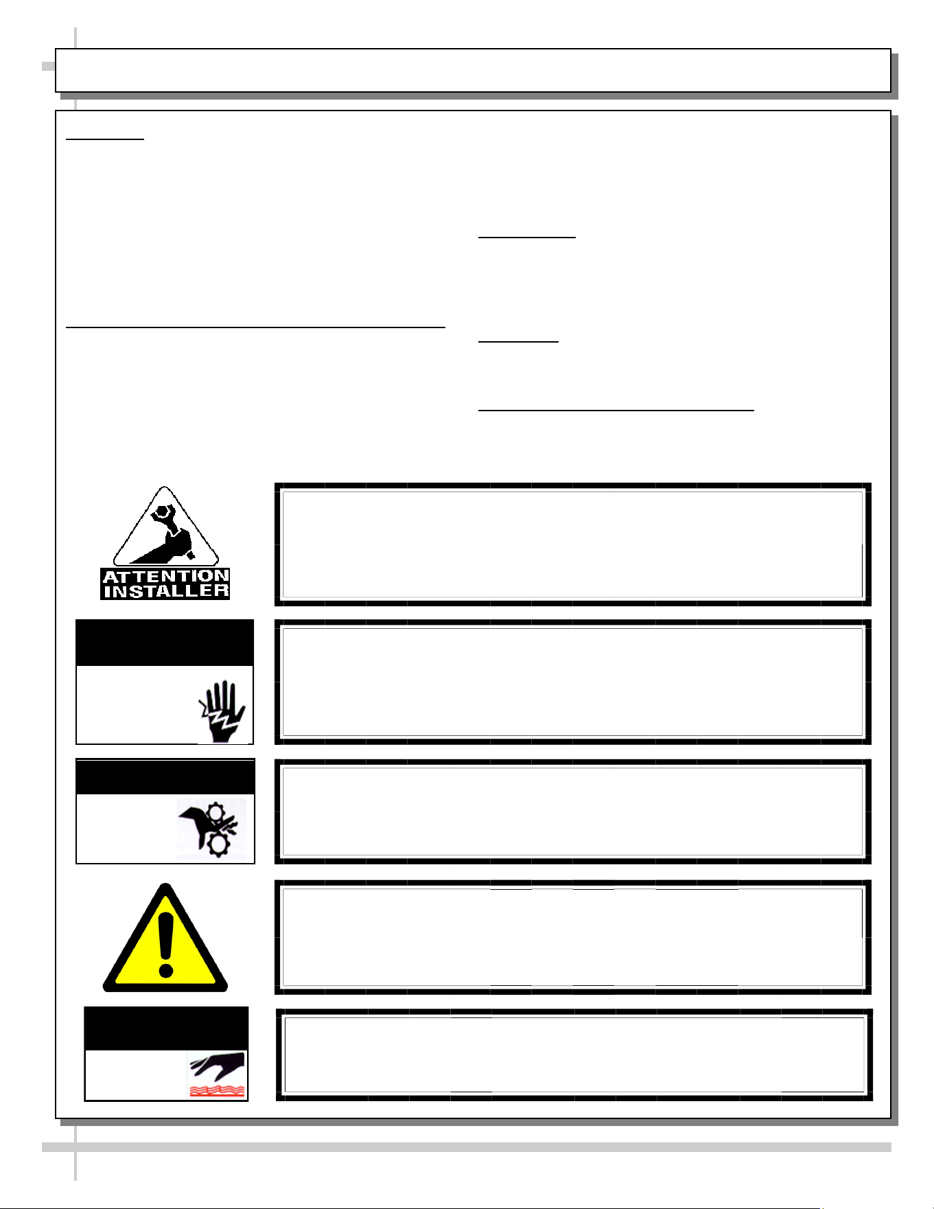
WARNING
Hazardous moving parts. Do not operate unit with covers removed.
Fan blades may be exposed when deck panel is removed.
Disconnect power before removing deck panel.
WARNING
Risk of electric shock. Disconnect power before servicing unit.
CAUTION! More than one source of electrical supply is
employed with units that have separate circuits.
Disconnect ALL ELECTRICAL SOURCES before servicing.
WARNING
ELECTRICAL
HAZARD
WARNING
KEEP
HANDS
CLEAR
COMPLIANCE
This equipment MUST be installed in compliance with
all applicable NEC, federal, state and local
electrical and plumbing codes.
OVERVIEW / TYPE / COMPLIANCE / WARNINGS / PRECAUTIONS / CORDS / WIRING - PAGE 1 of 3
WARNING
This product can expose you to chemicals, including
Urethane (Ethyl Carbamate), which are known to the state of
California to cause cancer and birth defects or other reproductive
harm. For more information go to P65Warnings.ca.gov.
WARNING
Condensate pan and overflow condensate pans are HOT!
Disconnect and allow to cool before cleaning or removing from case.
WARNING
HOT
SURFACE
PRECAUTIONS
• Following are important precautions to prevent damage
to unit or merchandise. Read carefully!
• See previous page for specifics on OVERVIEW,
CONDITION TYPE, COMPLIANCE and WARNINGS.
WIRING DIAGRAM
• Each case has its own wiring diagram folded and in its
own packet. It may be placed near ballast box, field
wiring box, raceway cover, or other related location.
REFRIGERANT DISCLOSURE STATEMENT
• This equipment is prohibited from use in California with
any refrigerants on the “List of Prohibited Substances” for
that specific end-use, in accordance with California Code
of Regulations, title 17, section 95374.
• This disclosure statement has been reviewed and
approved by Structural Concepts and Structural Concepts
attests, under penalty of perjury, that these statements
are true and accurate.
OVERVIEW / TYPE / COMPLIANCE / WARNINGS / PRECAUTIONS / CORDS / WIRING - PAGE 2 of 3
4
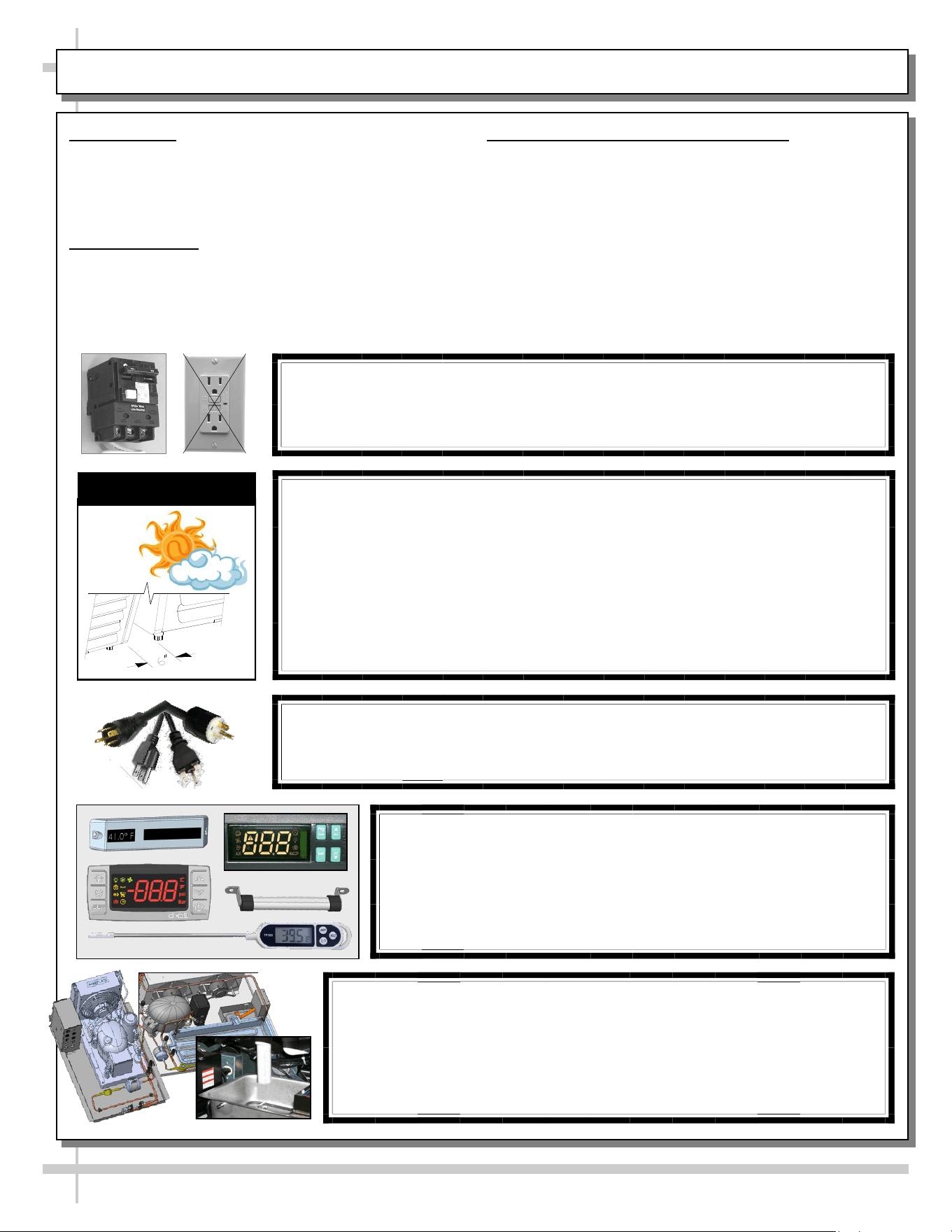
CAUTION! POWER CORD AND PLUG MAINTENANCE
Risk of electric shock. If cord or plug becomes damaged,
replace only with cord and plug of same type.
CAUTION! GFCI BREAKER REQUIREMENT
If N.E.C. (National Electric Code) or your local code
requires GFCI (Ground Fault Circuit Interrupter) protection,
you MUST use a GFCI breaker in lieu of a GFCI receptacle.
CAUTION! ADVERSE CONDITIONS / SPACING ISSUES
• Performance issues caused by adverse conditions are NOT warranted.
• To prevent damage to end panels due to condensation, apply industrial grade
silicone sealant and tightly join to opposite end panels. When not adjoining
cases, keep end panels at least 6” away from walls/structures. Rear panels
must also be kept at least 6” from walls and structures.
• Case must not be exposed to direct sunlight or any heat source.
• To maintain proper case temperature, keep case at least 15-feet from exterior
doors, overhead HVAC vents or any air curtain disruption.
• Self-contained case clearance: 6” min. air intake / 6” min. air discharge.
CAUTION
CAUTION! DO NOT RELY ON THERMOMETERS OR
THERMOSTATS FOR PRODUCT (FOOD) TEMPERATURES.
• Thermometers & thermostats reflect air temperatures ONLY.
• For ACTUAL product (food) temperatures, use a calibrated food
probe thermometers ONLY.
• For accurate readings, DO NOT use infrared food thermometers.
CAUTION! CHECK CONDENSATE PAN, ITS POSITION & PLUG!
Water on flooring can cause extensive damage!
• Before powering up case, check that condensate pan is positioned
directly under case’s condensate drain.
• Before powering up case, check that condensate pan’s electrical plug is
SECURELY connected to condensate system’s receptacle.
• If wicking material is used in condensate pan, check that it is secure.
5
OVERVIEW - CONTINUED
WEIGHT LOADS ON GLASS / PREVENTING SAGGING
• Caution! To prevent sagging, do not exceed 5 LB (2.3
KG) weight load per top glass section between
stainless steel posts (or supports).
OVERVIEW / TYPE / COMPLIANCE / WARNINGS / PRECAUTIONS / CORDS / WIRING - PAGE 3 of 3
CAUTION! TOP GLASS WEIGHT LOAD LIMIT
• To prevent sagging or breakage, do not exceed 5 LBS (2.3 KG)
weight load per top glass section (between posts and/or supports).
• To prevent scratching or marring, do not place ANY items on glass.
5
LBS
6
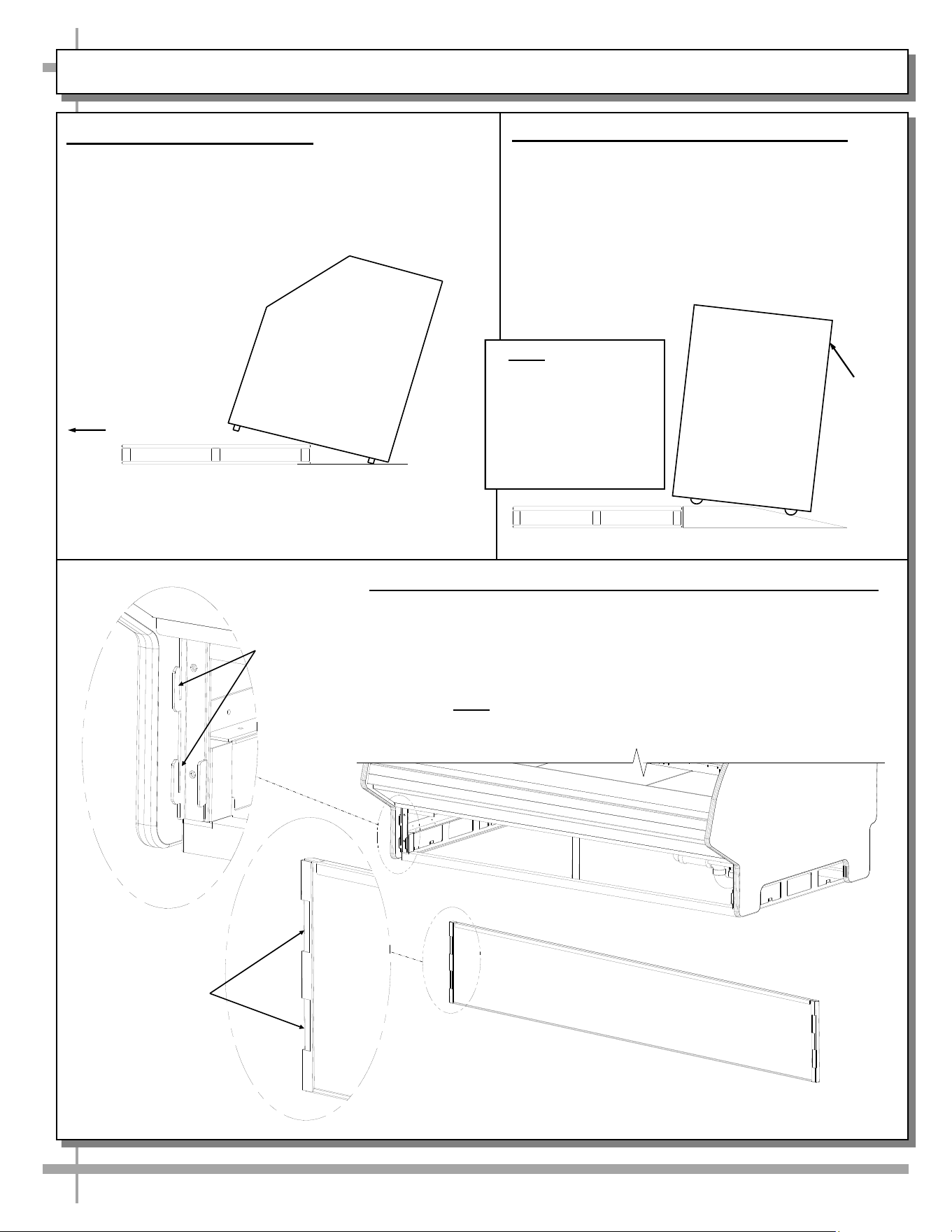
INSTALLATION: REMOVAL FROM SKID, REMOVING LOWER FRONT PANELS
1. Remove Case From Skid
• Remove shipping brace that may be
securing case to skid.
• Support case to prevent tipping.
• Caution! Rails can be damaged if case hits
floor with heavy force!
Case can be repositioned with pallet truck when
front lower panel is removed. Blocking may be
necessary to obtain adequate height.
Slide Skid Out
• Carefully slide unit to
rear of skid and tip
backward off skid.
• Illustration may not
reflect every feature
or option of your
particular case.
2. Remove Case From Skid (Casters)
Remove shipping brackets that may be securing
casters to skid
• Place ramp up against skid (to allow case to
smoothly slide off from skid).
• Maintain support of case at all times or center
of gravity may cause case to fall.
• Unlock Casters. Roll unit to rear of skid.
Ramp
Roll down ramp
and off from skid.
Support
while
rolling
case
down
ramp.
Note: Illustrations
shown reflect a
general outline of
sample cases and do
not reflect features or
options of your
particular model.
3. Removing Vertical Lower Front Panel (and Rear Panel)
Removing Lower Front Panel
• No screw removal is required to remove lower front panel.
• Simply lift lower front panel slots up and off case hooks.
• Replace in same manner it was removed.
• Rear panel is removable in same manner.
• Note: Illustrations below may not exactly reflect every
feature or option of your particular case.
Lower Front Panel
(Reversed to Show Slots
Hooks
Slots
Note: Illustration Shown
May Not Reflect Every
Feature or Option of Your
Particular Merchandiser.
7
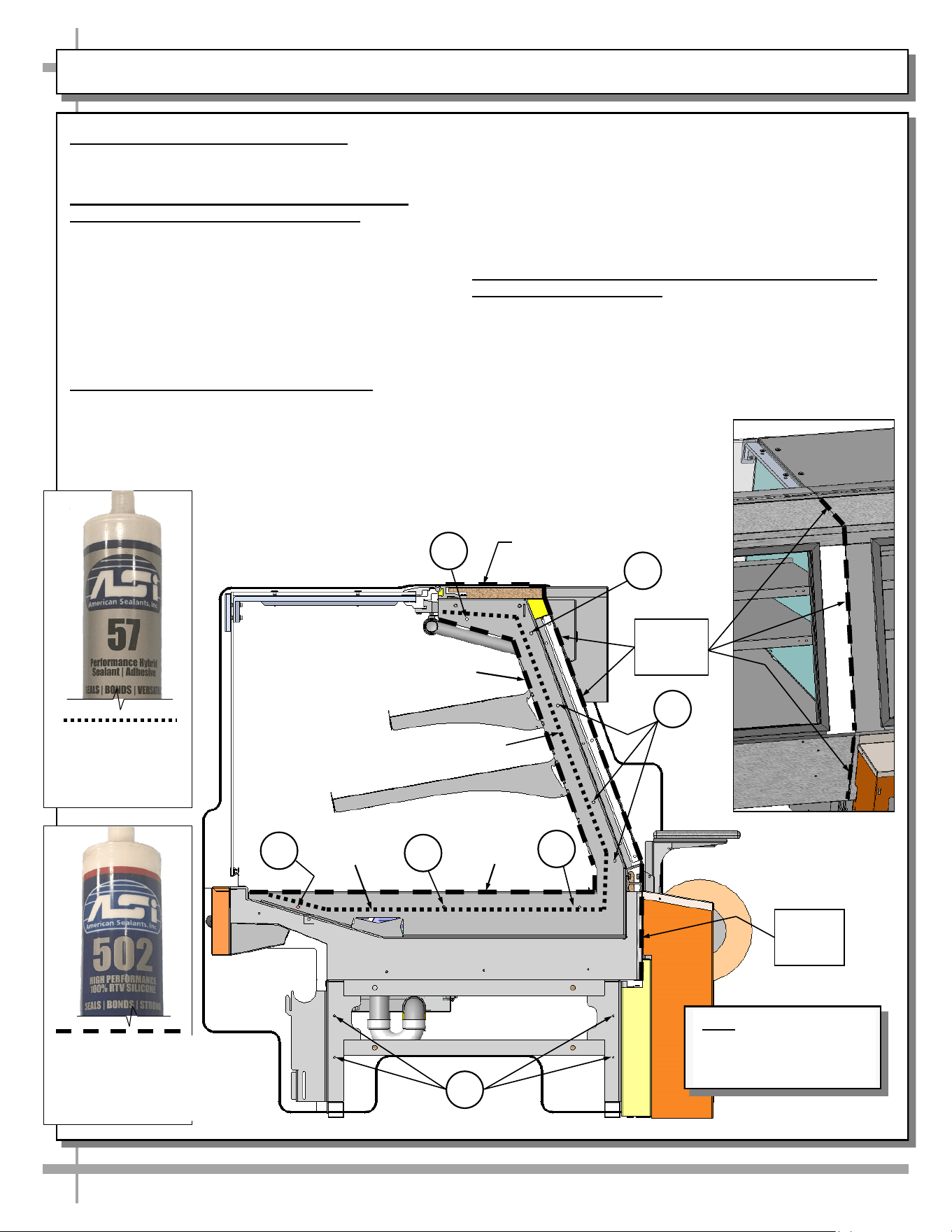
INSTALLATION, CONT’D: CASE ADJOINMENT INSTRUCTIONS
4. Case Adjoinment Instructions
>> Warranty is void if improper sealant/urethane is used.
>> Lay generous beads of sealant/urethane as specified.
A. Prior To Adjoinment - Apply Industrial Grade
Urethane Adhesive at Center of Uprights
• Lay a generous bead of industrial grade urethane
adhesive at center of uprights (in non-visible areas).
• This urethane adhesive prevents refrigerated air from
escaping between cases (causing condensation and
reducing refrigeration efficiency) as well as preventing
ants or other insects from entering case.
• See industrial grade urethane adhesive illustration
below-left.
B. Adjoining Cases - Using Bolts and Nuts
• Use appropriately sized nuts and bolts for each hole.
#1 - Hole is accessible through rear sliding door (if you
are able to avoid gas cylinder, attach bolt); otherwise
start at #2 in bolt/nut attachment process.
#2 - Holes are accessible through rear sliding door.
#3 - Holes are accessible at underside of decking.
Decking must be removed to attach bolts/nuts.
#4 - Holes are accessible at base frame (through front of
case after front toe-kick has been removed).
• Tighten nuts securely (but do not over-tighten).
• See illustration below.
C. After Adjoinment - Apply Food Grade Silicone Sealant
To Inner And Outer Seams
• After all nuts/bolts are securely attached to case, apply a
generous bead of food grade silicone sealant at both inner
and outer seams.
• When properly applied, this food grade silicone sealant will
prevent water from seeping between cases (into the case or
to the floor) as well as crumbs or other residue from
entering between case seams.
• See silicone sealant illustration
below-left.
>> You must reattach toe-kick and
decking after case adjoinment
process is complete.
1
2
3
3
3
4
Refrigeration
Bead
Inner
Sanitation
Bead
Inner Sanitation
Bead
Refrigeration
Bead
Outer Sanitation Bead
To Be Applied At Rear
Adjoinment Seams
(Shown Above)
Outer
Sanitation
Beads
2
Outer
Sanitation Bead
Outer
Sanitation
Bead
Industrial Grade
Urethane Adhesive
(For Refrigeration
Bead Applications)
Silver, Black or Clear
Silicone Sealant
Conforming To NSF/
ANSI 51 Specs (For
Sanitation
8
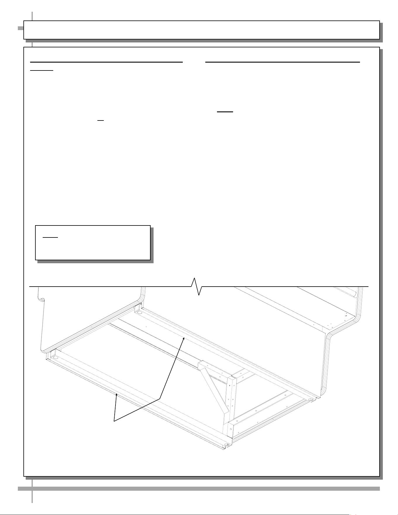
INSTALLATION, CONT’D: POSITIONING & ALIGNING CASE / FRAME SUPPORT RAIL SHIMMING
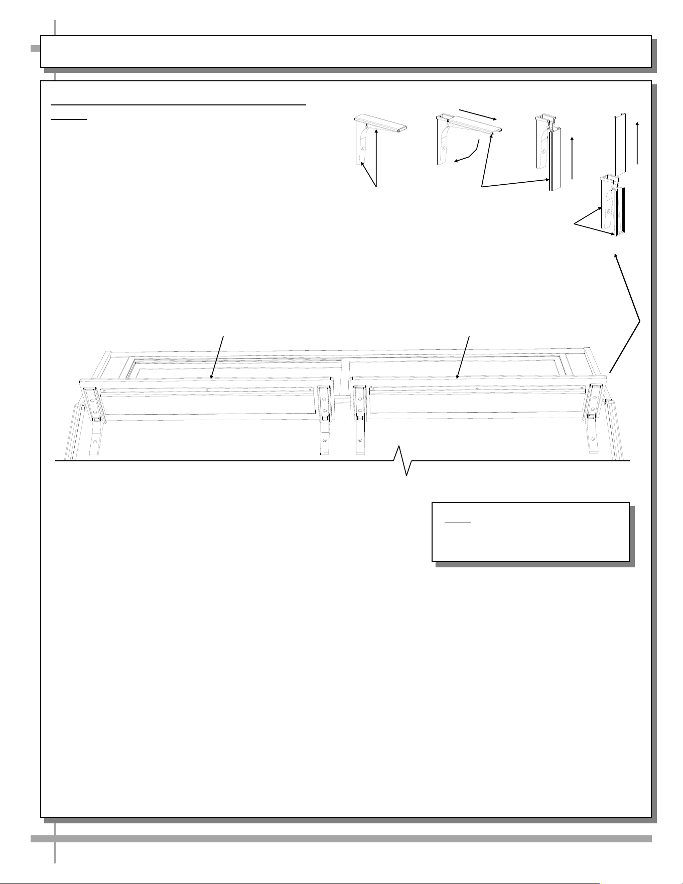
5. Position & Align Case Alongside Other
Cases
• Before adjusting levelers (or shimming frame
support rails), make certain that the case is in
proper position and, if required, aligned with
adjoining case.
• This may require the repositioning of the case
you are installing or the already positioned case.
• Though case below shows both end panels,
case adjoinments routinely consist of end panel
removal for case-to-case placement.
Frame Support
Rails
6. Frame Support Rails Must Be Shimmed
• Illustration below shows case with frame
support rails.
• Shims will be provided with all cases that have
frame support rails.
• Use shims to level case.
• Note: After case is in position, it must be
sealed to floor to prevent entry or leakage
of liquid or moisture.
Note: Illustration shown may not
exactly reflect every feature or
option of your particular unit.
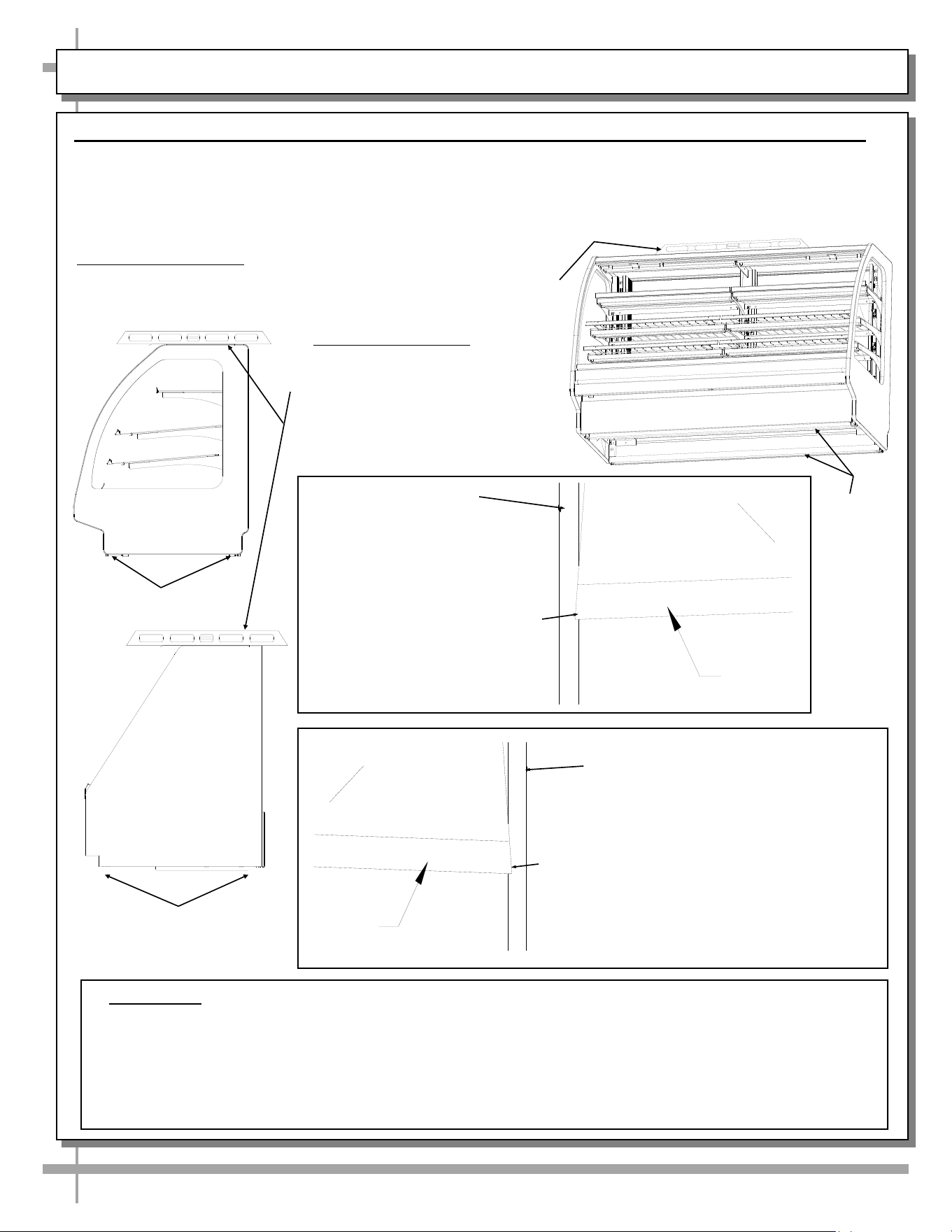
INSTALLATION, CONT’D: FRONT GLASS ALIGNMENT & ADJUSTMENT (VIA RAIL SYSTEM)
9
Case with Curved
Front Glass
7. Front Glass Alignment & Adjustment via Rail System (For Curved and Flat Front Glass)
• Proper alignment of the front glass is important to create and maintain a seal inside the case.
• Improper alignment can cause air leaks compromising the environment inside the case and create condensation.
• Follow the five steps listed below to assure proper front glass alignment.
• Illustrations shown may not exactly reflect every feature or option of your particular case.
B. Front-to-Back Leveling:
• Place a level on top of case,
perpendicular to the front glass.
• Raise or lower either side of case
by shimming under the rails
(following steps 3 & 4 below).
• Double-check the side-to-side level.
A. Side-to-Side Leveling: Place a level on top of display case (parallel
to front glass). Raise or lower either side of case by inserting shims
under the rails to level the case (following steps 3 and 4 below).
E. Verification:
• After inserting shims, open and shut the front glass.
• Verify (again) that the front glass is properly aligned at both left-hand and right-hand side of
the case.
• If not, repeat the shimming procedure until the front glass is properly aligned along both sides
of the case.
CURVED
FRONT
GLASS
END
PANEL
LIFT
4. If FRONT-RIGHT CORNER is too close
to end panel (or hitting it), insert shims at
the BACK RIGHT CORNER of case.
LIFT
END
PANEL
CURVED
FRONT
GLASS
C. If FRONT-LEFT CORNER
is too close to end panel (or
hitting it), insert shims at the
BACK LEFT CORNER of case.
END PANEL
Case with Flat
Front Glass
END PANEL
Rails
Rails
Rails
D. If FRONT-RIGHT CORNER is too close
to end panel (or hitting it), insert shims at
the BACK RIGHT CORNER of case.
10
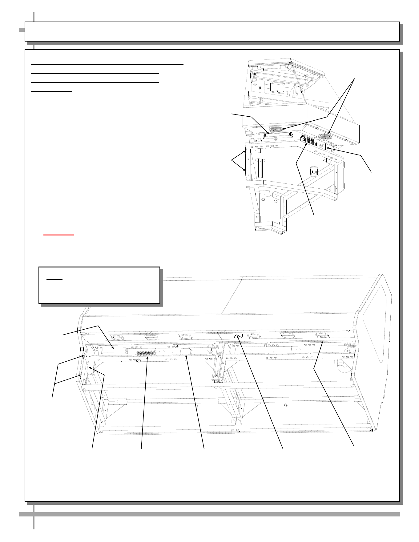
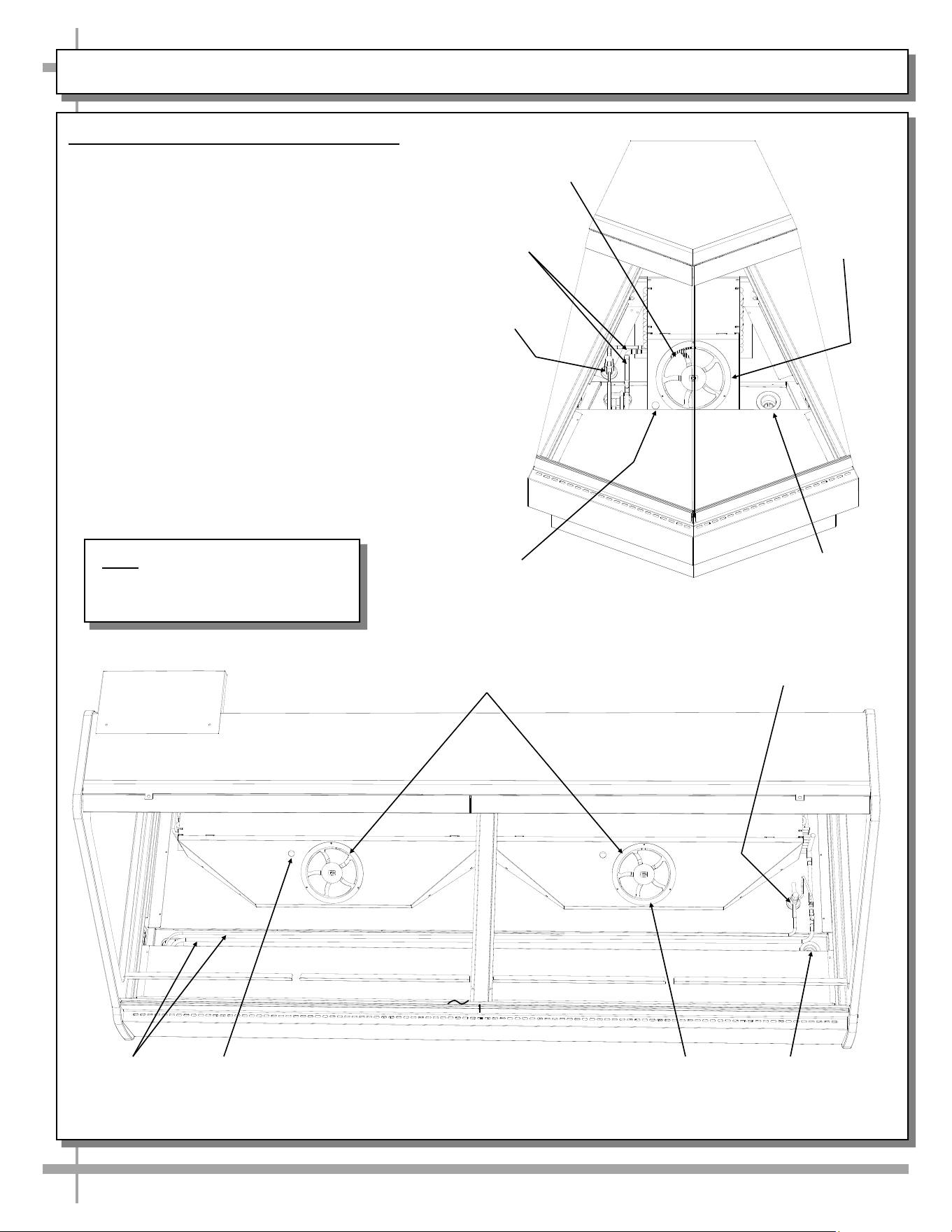
8. Probe Leads Box / Field Wiring Box /
Ballast (or Optional LED Driver) /
Terminal Strip / Anti-Condensate
Axial Fans
• Probe leads are in probe leads box (on
certain models). It is located at customer
front-left of case (behind front panel).
• Field wiring box is also located at front left
of case (behind front panel)
• Ballast (or optional LED driver) and terminal
strip is also located behind front electrical
cover (shown removed for illustrative
purposes).
• Screws hold front electrical cover in place.
Unscrew and drop electrical cover down
and out.
• Anti-condensate axial fans (for front glass)
may be accessed (at underside of front
panel) by simply removing four screws, and
dropping fans down.
• Caution! Only certified electricians are
to access electrical components!
Front Electrical Cover
Removed for
Illustrative Purposes
(2) Hooks at
Each End
for Front
Panel Slots
Terminal
Strip
Light
Ballast
LED Driver (Optional,
Dependent Upon
Lighting)
Probe
Leads Box
--- View of GMDS8R With Front Panel and Electrical Cover Removed ---
Anti-Condensate
Axial Fan (Typ.)
INSTALLATION, CONT’D: PROBE LEADS / FIELD WIRING BOX / BALLAST / OPTIONAL LED DRIVER
--- View of GMDSX4R With Front Panel
and Electrical Cover Removed ---
(2) Hooks
at Each
End for
Front
Panel
Slots
Terminal
Strip
Light
Ballast
LED Driver
(Optional,
Dependent
Upon
Lighting)
Anti-Condensate
Axial Fans
Note: Illustration shown may not
exactly reflect every feature or
option of your particular unit.
11
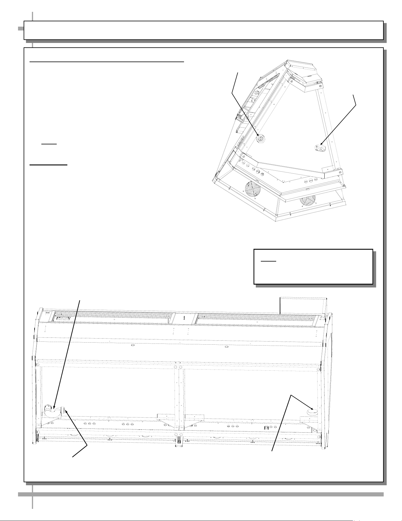
INSTALLATION, CONT’D: REFRIGERATION LINES / STUB-UPS / DRAINS
9. Refrigration Line Stub-Up Connections
• Refrigerant stub-up access is at underside of
case.
• Stub-up connections are accessed by removing
rear panel (no screws required).
• Run case-to-case connections through cutouts in
base.
• Sweat the high and low pressure connections.
• Fill access hole with suitable filler to insure
watertight integrity of tub.
• Note: Illustration below may not reflect every
feature or option of your particular case.
10. Drains
• Cases have drains at left and right hand sides.
• Longer cases may have drain at case center.
• Drain field connection location as shown.
• See next page for illustration of TXV Valve,
Drains, Refrigeration Line Stub-Ups Access, etc.
• Depending upon drain access needs, either front
or rear panel may be removed to gain access to
drain stub-up.
• 1.5” male PVC stub-up connection is under case.
• Drain stub-up may be at case center in extended
length cases.
• Connect tub drain to floor drain. Maintain
1/4”-fall per foot to provide proper drainage.
Refrigeration
Line Stub-Ups
Access
Field Connection
for Drain
Model GMDS8R is Shown
Above. Your Case May Differ.
P-Trap
Model GMDSX4R isShown Above.
Field Connection
for Drain
Refrigeration
Line Stub-Ups
Access
Note: Illustrations shown may not
exactly reflect every feature or
option of your particular unit.
12
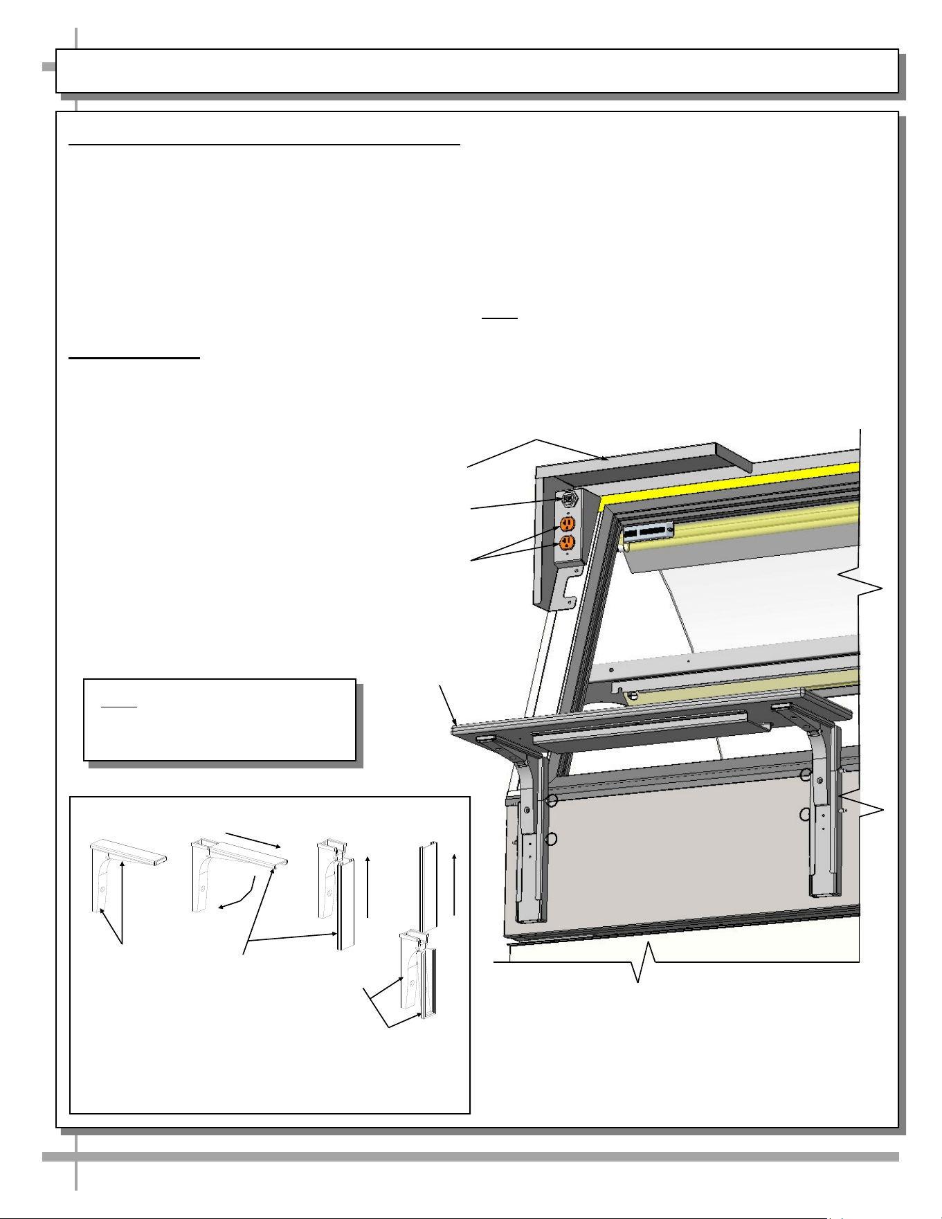
INSTALLATION, CONT’D: SCALE STAND WITH OUTLETS & CAT5 / FLIP-UP LEDGE
—— Optional Rear Ledge Removal Steps ——
Note: For clarity, only Shelf Track is shown being
removed. Rear Ledge is attached to Shelf Track.
Hinged
Support
Bracket
Shelf
Track
-1- -2- -3-
-4-
Hinged
Support
Bracket
11. Scale Stand / Ethernet CAT5 / Receptacle
• Optional scale stand location and illustration is
shown below.
• Route the scale stand cord through into
receptacle (shown below).
• Plug scale stand cord into receptacle as shown
in illustration below.
• Depending upon options chosen, CAT5
(Category 5) network cable outlet may also be
available at scale stand base (as shown below).
12. Rear Ledge
Rear Ledge is connected to Shelf Track. See below
for Rear Ledge removal steps.
Rear ledge step-by-step removal method is as follows:
1. Hinged Support Bracket is shown in
its standard upright position.
2 & 3. While upright, Rear Ledge must be
slid away from case and then rotated downward to
vertical position.
3 & 4. From the shelf’s lowered position, lift from
bottom edge upward to disengage shelf track (and
attached Rear Ledge) from bracket.
Note: Illustrations shown may not exactly reflect every
feature or option of your particular case.
Sanalite Flip-Down
Ledge
Scale Stand
Ethernet CAT5
Model GMDS10R.5773F Shown Above.
Your Model May Vary
110V Electrical Outlets
Note: Illustration shown may not
exactly reflect every feature or
option of your particular unit.
13
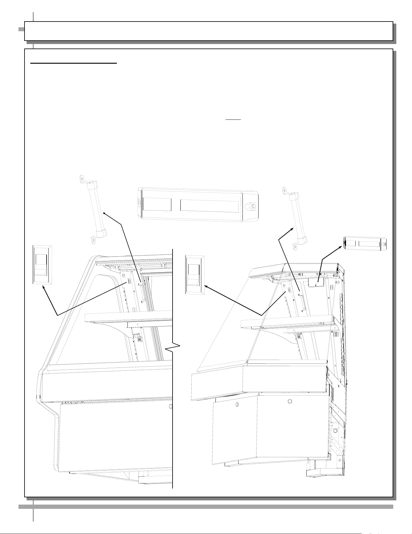
START-UP AND OPERATION
Merchandiser Start-Up
• Unit will energize when properly field wired.
• Evaporator coil fans will automatically turn on.
From the front of the case, lift glass and remove
the decking; check to see that the coil fans are all
functioning properly.
• Lights switch is accessible at case front-left, near
upright. See illustration below.
• Turn light switch on. All lights should come on at
the same time. First time lighting may require a
short warm up-period for the bulbs.
• Slightly dim or a flickering of new bulbs is normal.
Digital Thermometer
• If lights do not turn on, check all raceway
plugs. The lighting is wired in series so all
lights must be plugged in or receptacles
capped in order for the case to light.
• Refrigeration section has been tested to
maintain temperature at or below 5 °Celsius /
41 °Fahrenheit.
• Note: Thermometers provided with equipment
reflect internal air temperature only (not actual
food temperature). Use probe thermometers to
determine actual product temperatures.
41°F
Light
Switch
Light
Switch
or
Spirit-Filled
Thermometer
or
Spirit-Filled
Thermometer
41°F
Digital
Thermometer
Viewable at
Case Rear
14
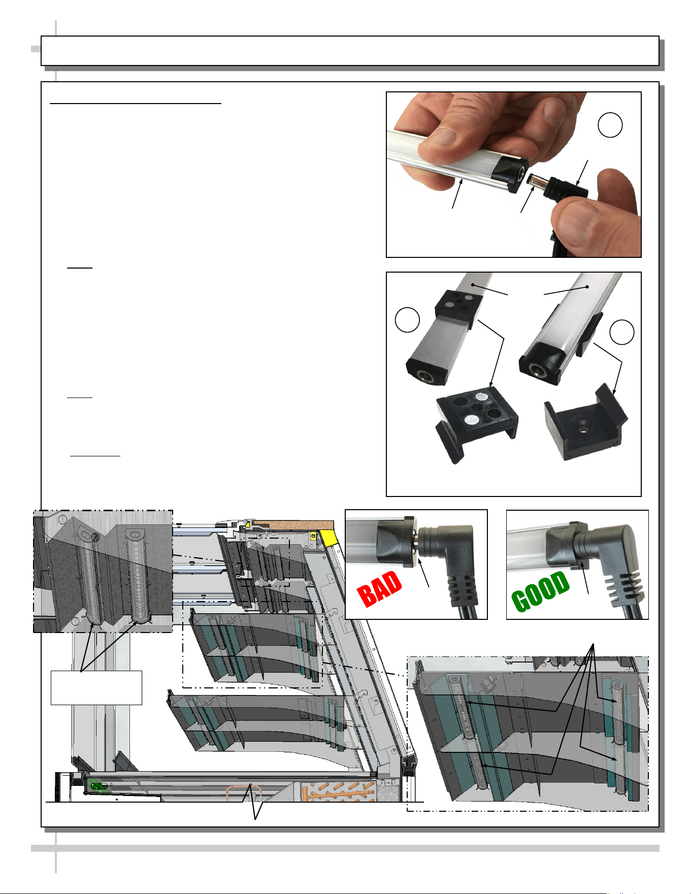
1. LED Style Light Fixtures
Removal of Faulty LED Lights:
• Contact Structural Concepts’ Technical Service
Department for replacement LED lights.
• Turn off LED light switch.
• To remove faulty LED light, follow these steps:
A. Disconnect plug from LED light.
B. Using both hands, grasp LED light assembly (with its
magnetic mounting clips). Pull downward and off its
shelf (or header).
C. Remove magnetic mounting clips from LED light by
pressing against flange part of clip with thumb.
>> Note: Mounting clips MAY be riveted to shelf or header.
In such instances, simply remove LED light from mounting
clips by pressing against flange part of clips with thumb.
Replacement of LED lights:
• Attach magnetic mounting clips onto LED light.
• Adjust magnetic mounting clips so they are equally
spaced on LED light.
• Reattach LED light assembly to its shelf/header.
• Position properly in shelf/header.
>> Note: If mounting clips are riveted to shelf (or header),
attach by placing LED in base of clip and then snapping into
clip at FLANGE SIDE.
• Press plug’s barrel-shaped insert deep into LED light.
• Important: If plug is not inserted ALL THE WAY IN the
LED light’s orifice, the light may not energize. See
“BAD” vs. “GOOD” insertion illustrations below-right.
• Turn LED light switch back on.
MAINTENANCE FUNDAMENTALS: LED LIGHT FIXTURES / REMOVAL & REPLACEMENT
LED Lights In
Header (Typ.)
LED Shelving Lights
Magnetic Mounting
Clip View #2
LED
Lights
B
A
Plug
Barrel
Shaped
Insert
LED
Light
C
Magnetic Mounting
Clip View #1
No Gap
Gap
15
MAINTENANCE FUNDAMENTALS, CONT’D: SHELF ASSEMBLIES
2. Shelf Assembly (Standard Style)
• Shelves may be removed from uprights for
cleaning or service.
• For lighted shelving, unplug the light cord and
detach from the rear shelf support prior to
removing from case.
• Remove brackets. Note: It may be necessary
to remove the bracket retainer. Pliers will be
required to accomplish this task; pull bracket
retainers out of upright toward front of case.
Shelf
Bracket Retainer
(one for each shelf)
Rear Rack
Support
Bulb
Front
Toe-Kick
Shelf
Light
Assembly
Front
Panel
• Note: Depending upon model and options chosen,
shelf assembly may be tilted forward at 5°
increments (see illustration below right).
• See next page for additional shelf assembly styles
(and step styles) on various models.
5° Notches Allow Shelf
To Be Tilted
Note: Illustration shown may not
exactly reflect every feature or
option of your particular unit.
16
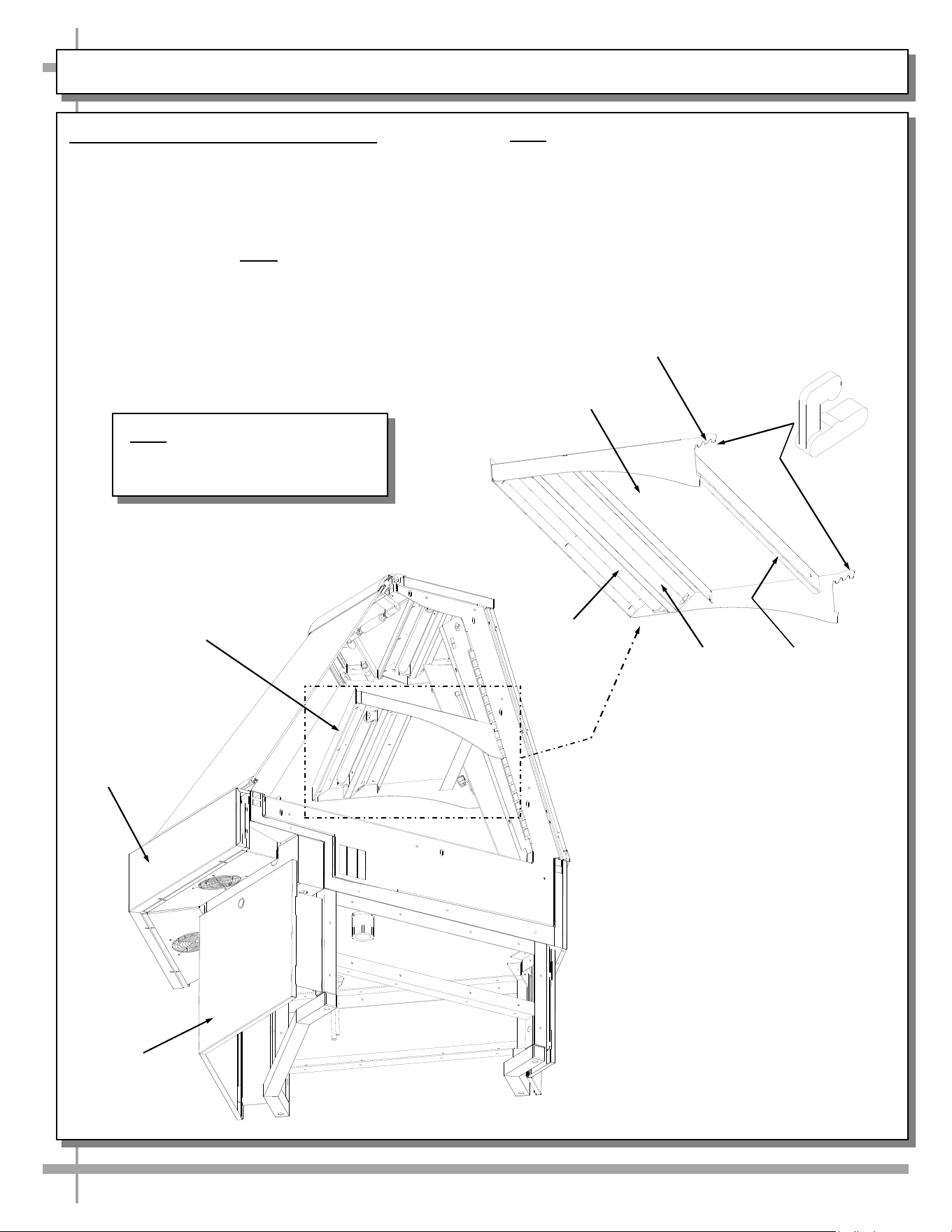
MAINTENANCE FUNDAMENTALS, CONT’D: SHELF ASSEMBLIES / STEPS
3. Shelf Assembly (Optional Styles)
• Shelves may be removed from uprights for
cleaning or service.
• For lighted shelving, unplug the light cord and
detach from the rear shelf support prior to
removing from case.
Step
Top Front Shelf With
Acrylic Product Stop
4. Steps
• Steps can vary in size and style.
• Models GMDSES6R / GMDSES8R /
GMDSES12R offer optional steps as shown
below. Your unit’s style may vary.
• See next page for additional shelf assembly and
step styles.
Bottom Front Shelf With
Acrylic Product Stop
Top Rear Shelf
Bottom Rear Shelf
Deck
Deck
Models GMDSES6R / GMDSES8R / GMDSES12R
Offer Above Options
17
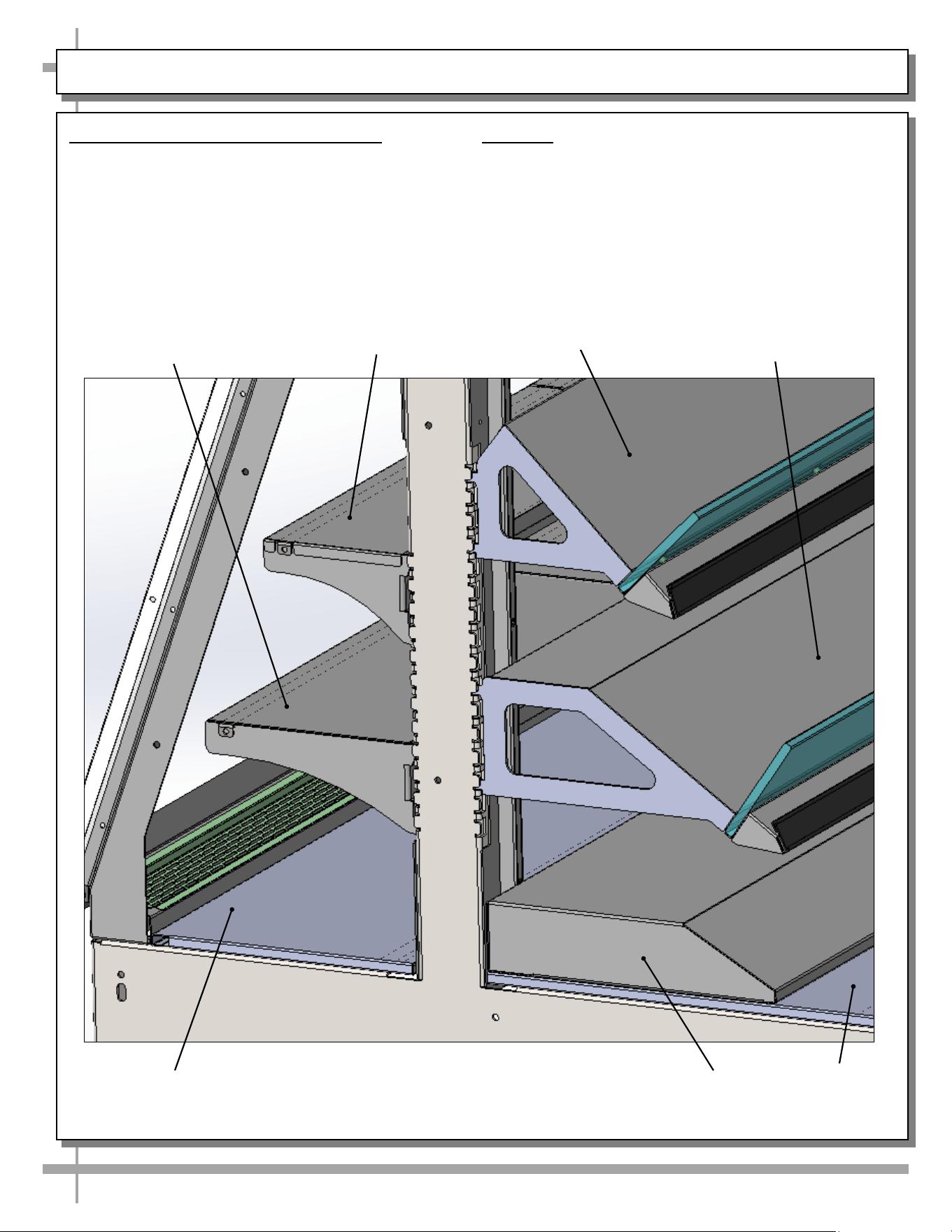
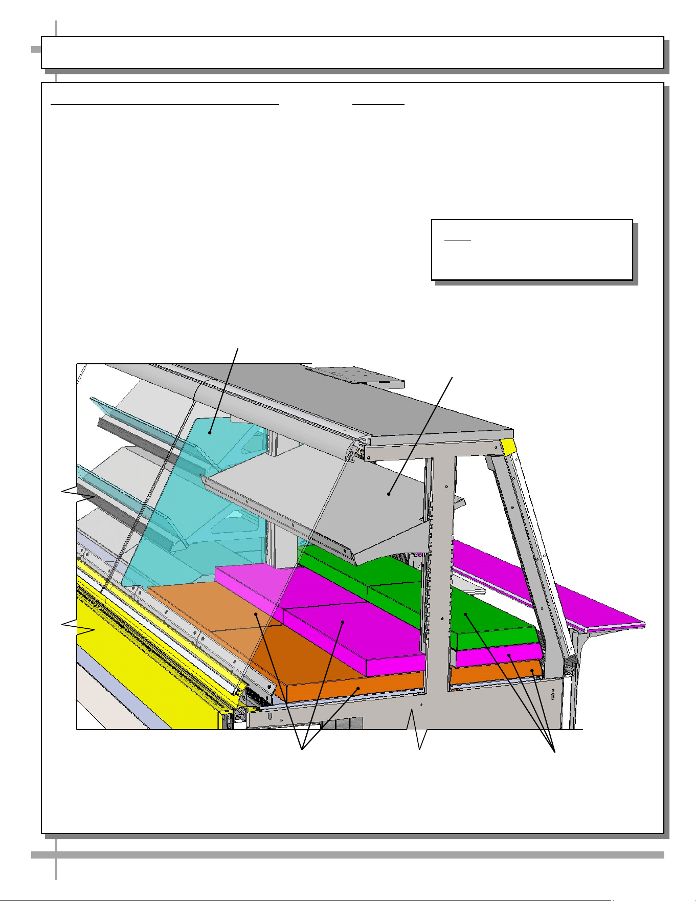
MAINTENANCE FUNDAMENTALS, CONT’D: SHELF ASSEMBLIES / STEPS
5. Shelf Assembly (Optional Styles)
• Shelves may be removed from uprights for
cleaning or service.
• For lighted shelving, unplug the light cord and
detach from the rear shelf support prior to
removing from case.
• Models GMDSES6R / GMDSES8R /
GMDSES12R offer shelf assembly designs
shown below. Your unit’s style may vary.
Steps
Optional Divider
Glass
6. Steps
• Steps vary in size and style.
• Models GMDSES6R / GMDSES8R /
GMDSES12R offer optional steps as shown
below. Your unit’s style may vary.
• See previous page for additional shelf assembly
and step styles.
Top Front Shelf
With Product Stop
Steps
Models GMDSES6R / GMDSES8R / GMDSES12R
Offer Above Options
Note: Illustration shown may not
exactly reflect every feature or
option of your particular unit.
18
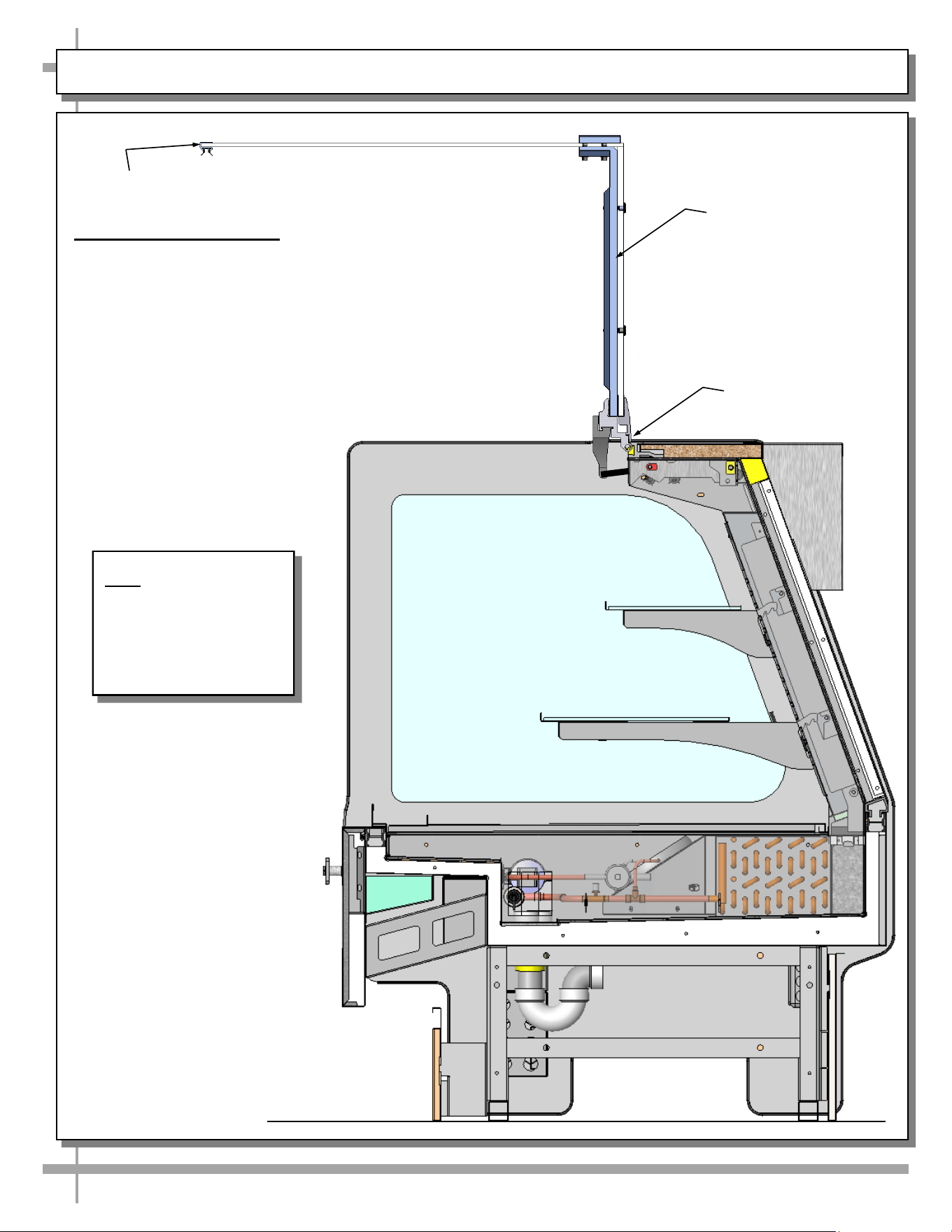
MAINTENANCE FUNDAMENTALS, CONT’D: DRAIN / TXV VALVE ACCESS
7. Drain and Expansion Valve Access
• The drain and expansion valve are both
accessible from the front of the case.
• Unplug the fans (one plug per side) and
remove the fastener from the access panel in
the front right (or left) corner of the unit.
• The drain and the expansion valve (TXV) is
directly below the access panel.
Fan Plug
(Typical)
Evaporator
Fan
Model GMDS8R is Shown Above
With Pans & Shelf Removed.
Your Case May Differ
Model GMDSX4R is Shown Above
With Pan & Shelf Removed
Evaporator
Fans
Drain
TXV Valve
Refrigeration
Lines
Evaporator
Fan
Drain
Refrigeration
Lines
TXV Valve
Fan Plug
(Typical)
Evaporator
Fan
Note: Illustration shown may not
exactly reflect every feature or
option of your particular unit.
19
MAINTENANCE FUNDAMENTALS, CONT’D: REAR SLIDING DOORS
8. Rear Sliding Doors
Note: Doors are not interchangeable. There is an
inner and outer door. The outer must be removed
first and replaced last.
• The outer door is the right hand door (from the
service side or rear of case).
• It is identified by a stop located at the lower right
hand corner to the inside of the case.
• Move doors toward the center of the case.
• Individually lift each door up toward the top of the
case; pivot the bottom of the door out.
• Carefully set rear sliding doors down to prevent
them from falling.
• Replace rear sliding doors in reverse order they
were removed.
• Caution! If rear sliding doors become loose,
sloppy or DO NOT stay in their door tracks, they
could fall out causing damage or injury! Bottom
door guides may need to be replaced.
>> See PREVENTIVE MAINTENANCE - TO BE
PERFORMED BY TRAINED SERVICE
PROVIDERS ONLY section in manual for
specifics.
--- Case With Single Set of Rear Sliding Doors ---
Note: Illustration shown may not
exactly reflect every feature or
option of your particular unit.
20
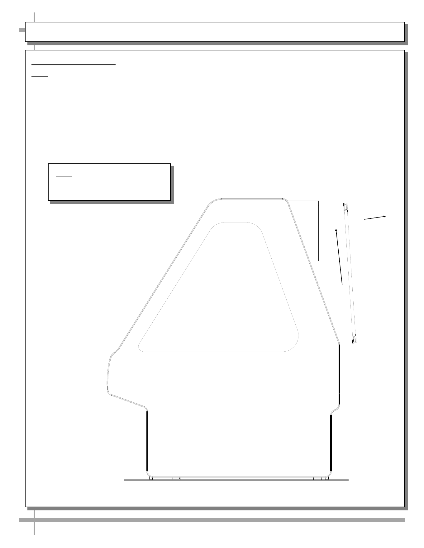
MAINTENANCE FUNDAMENTALS, CONT’D: REAR LIFT FRONT GLASS
9. Rear Lift Front Glass
• Model GMDSV3R.6694 (and possibly other models)
has UV-glued front glass may be raised via hinge that is
located near case rear.
• Simply grasp lift handle and raise upward.
• Front glass will raise up to 90° (as shown in illustration).
• Raised glass allows front access for product re-stocking
and/or cleaning purposes.
• Lower front glass slowly to prevent damage to unit.
Rear Lift Front Glass
(Shown In Raised
Position)
Hinge
Note: Illustration shown
reflects Model
GMDSV3R.6694.
It may not reflect every
feature or option of
your particular unit.
Lift Handle
21
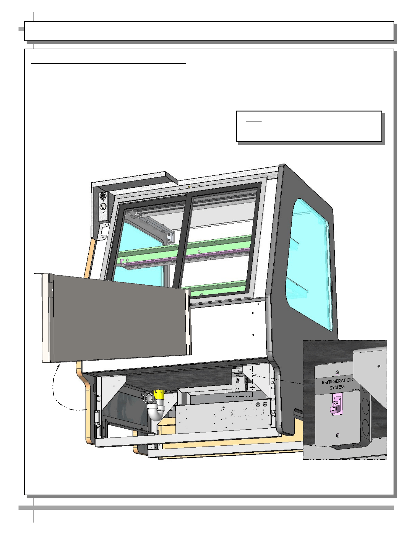
MAINTENANCE FUNDAMENTALS, CONT’D: REFRIGERATED TO DRY SWITCH (OPTIONAL)
10. Refrigerated to Dry Switch (Optional)
Model GMDSV3R.6694 (and possibly other models)
may be able to switch from refrigerated to dry
(non-refrigerated), if this option is chosen
• To access switch, simply lift rear toe-kick up and
off case (as shown below).
• Only authorized store personnel are to access
switch.
• After unit has been set to desired state (either
refrigerated or dry) via rear switch, return rear
toe-kick to case.
Case With Single Set of Rear Sliding Doors
Note: Illustration shown reflects Model
GMDSV3R.6694. It may not reflect every
feature or option of your particular unit.
22
MAINTENANCE FUNDAMENTALS, CONT’D: CUTTING BOARD / REAR LEDGE REMOVAL
11. Cutting Board / Rear Ledge Removal
Steps
The illustrations at right and below reflect
step-by-step removal method.
1. Hinged Support Bracket is shown in
its standard upright position.
2 & 3. While upright, Rear Ledge must be
slid away from case and then rotated downward
to vertical position.
3 & 4. From the shelf’s lowered position, lift from
bottom edge upward to disengage shelf track
(and attached Rear Ledge) from bracket.
————— Rear Ledge Removal Steps —————
Note: For clarity, only Shelf Track is shown being
removed. Rear Ledge is attached to Shelf Track.
Hinged
Support
Bracket
Shelf
Track
-1- -2- -3- -4-
Hinged
Support
Bracket
Cutting Board Cutting Board
Note: Illustration shown may not
exactly reflect every feature or
option of your particular unit.
23
MAINTENANCE FUNDAMENTALS, CONT’D: REFRIGERATION PACKAGE LAYOUT
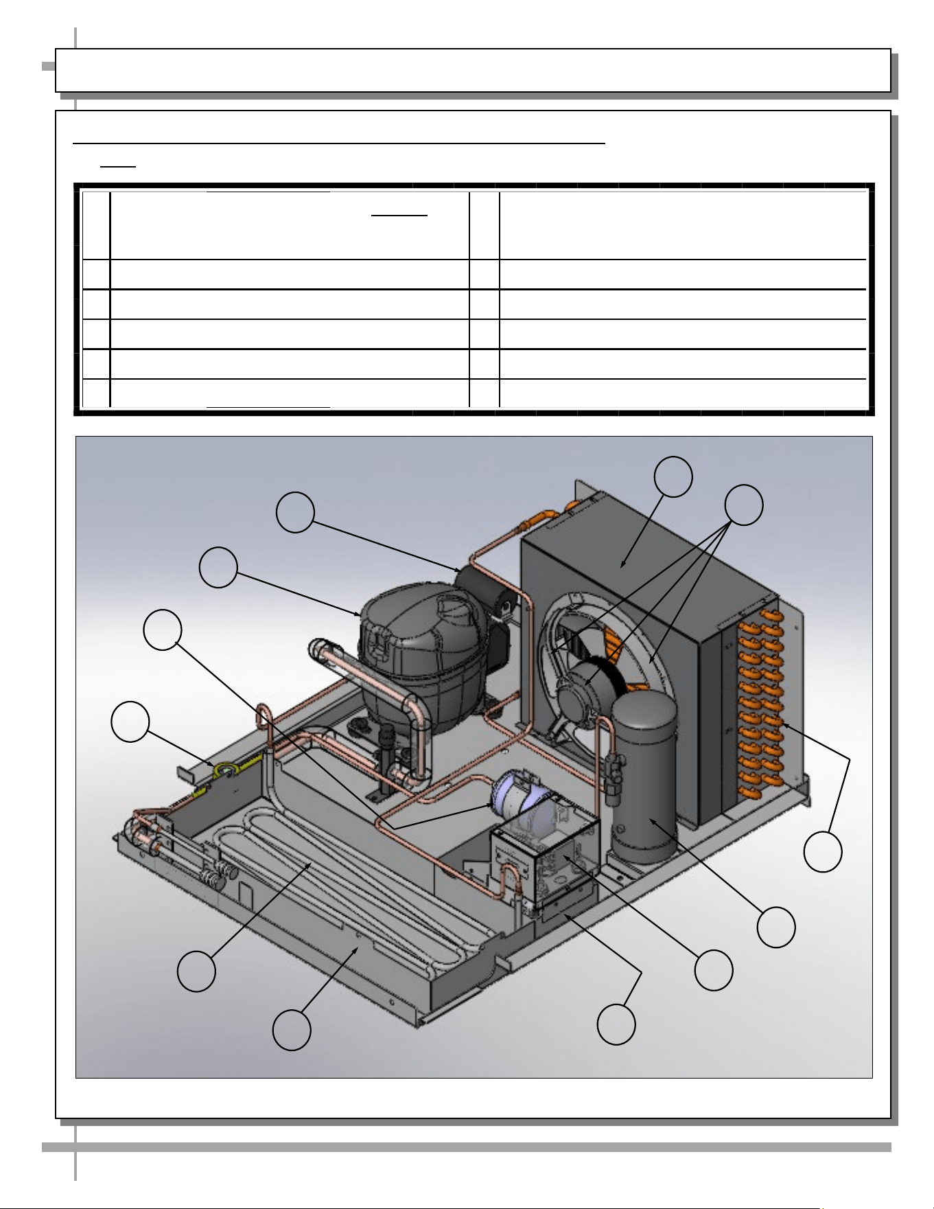
12. General EnergyWise Refrigeration Package Configuration
• Note: Your particular compressor may have slightly different refrigeration package layout.
1
Fan Shroud / Condenser Coil Cover: (Optional:
May Have Shroud Attached to House Clean
Sweep™ Automatic Condenser Coil Cleaner)
7 Hot Gas Condensate Evaporator Pan
2 Fan Motor & Bracket 8 Hot Gas Loop
3 Condenser Coil Tubing 9 Sight Glass
4 Receiver 10 Filter / Drier
5 Electrical Box (To Overflow Condensate Pan) 11 Hot Gas Loop Compressor
6 Overflow, Hot Gas Condensate Evaporator Pan 12 Start Components, Hot Gas Loop Compressor
1
2
3
4
5
6
8
9
10
11
12
7
24
MAINTENANCE FUNDAMENTALS, CONT’D: REMOTE UNIT FIELD ACCESS BOX / MISTING SYSTEMS
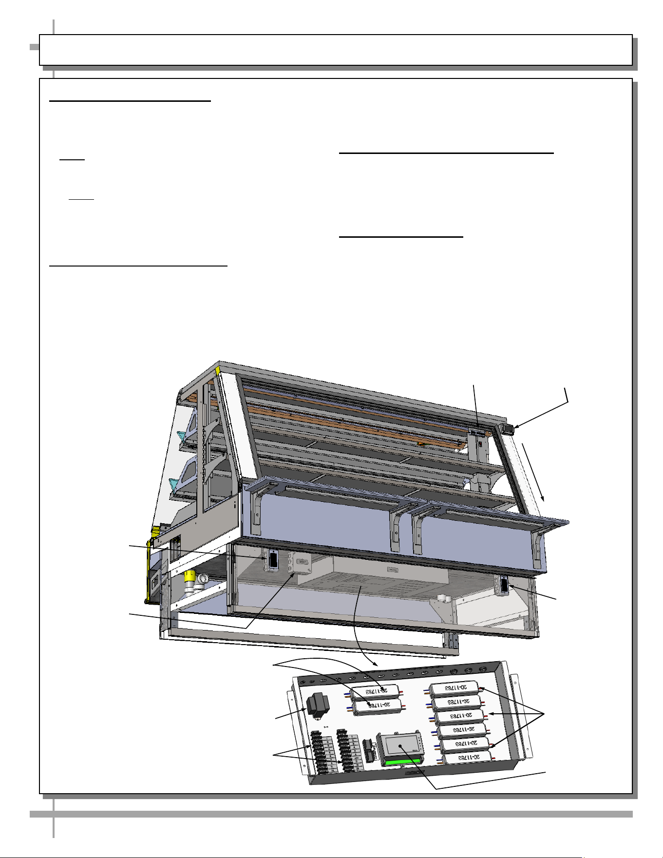
13. Electrical Connections
Field Access Boxes, Electrical Outlets, LED
Drivers, Circuit Board, Transformer, Terminal
Strips, Programmable Controller, Etc.
> Note: Rear panel is shown transparent.
• Access to field access box is at case rear with
rear panel removed (no screw removal required).
• Note: Wiring process must be performed by
certified electrician only.
• When case is properly field-wired, it will energize
(no main power switch required).
14. Programmable Controller
• Programmable controller is in the pull-out
electrical box (accessible at case rear).
• Programmable controller display is also at
case rear (as shown at upper-right below).
• See Programmable Controller Information
section in this user manual for additional
information.
15. Model Illustration Compatibility
• Model shown below is GMDSE6R.
• Models GMDSE8R & GMDES12R have similar
remote layouts.
• Your model may slightly differ.
16. Misting Systems
• Certain units have misting systems.
• To prevent ice buildup, misting systems
MUST BE placed in extended manual defrost on
a weekly basis.
• See next page’s Interior Weekly Extended
Manual Defrost section for additional
information.
2 x 4 Outlet
Programmable
Controller
Display
Transformer
LED Drivers
(Typical)
T-Blocks
Temperature
Controller
LED Drivers
(Typical)
Thermometer
2 x 4 Outlet
4 x 4 Field
Access Box
25
CLEANING SCHEDULE - INTERIOR: TO BE PERFORMED BY STORE PERSONNEL
AREA FREQ. INSTRUCTIONS
Interior Daily Decks: Wipe off decks with moist cloth dipped in mild soap and water solution.
Weekly Extended Manual Defrost (For Units With Misting System Only):
• Units with misting system can have ice buildup occur (causing case to operate
outside acceptable temperatures). Models include GMDSV8R.7063B and
GMDSV12R.7063D. However, misting systems may also be on other models.
• To prevent ice buildup, case must be placed in extended manual defrost until all
ice that may have built up in evaporator coils has thawed. This procedure may
take several hours.
• If uncertain of proper extended manual defrost procedure, see your controller’s
instruction guide OR contact your facility’s maintenance/service manager.
Monthly Tub and Drain (Trained Service Providers Only):
• Caution! Turn off power to unit before proceeding.
• Area at underside of decking must be kept free of debris which could clog tub
and drain. To access drain area, remove the deck and fan shroud.
• Use spray bottle and brush to dislodge residue. Use wet-vac on tub, trough and
drain to remove residue.
• Caution! Avoid splattering water over the case and surrounding areas!
Monthly Condensing Coil:
• Remove grille (by lifting up and off).
• Use air pressure or industrial strength vacuum; clean dust and dirt that may
collect on the condenser coil.
• Caution! Coil fins are sharp. Handle with care!
• Replace rear grille. No screw attachment is necessary.
26
CLEANING SCHEDULE - EXTERIOR: TO BE PERFORMED BY STORE PERSONNEL
AREA FREQ. INSTRUCTIONS
Exterior Daily All Glass / Mirrors: Clean side glass, front glass and mirrors with household or
commercial glass cleaner. Clean out door track with moist cloth.
Daily Rear Sliding Door Exterior Glass: Clean with household or commercial glass
cleaner.
Daily End Panels, Front Panel, Toe-Kick, etc.: Wipe off all surfaces with warm water
and mild soap solution and non-abrasive cloth.
Weekly Wood, Laminate and Painted Surfaces: Clean with mild soap and water solution
and a soft cloth .
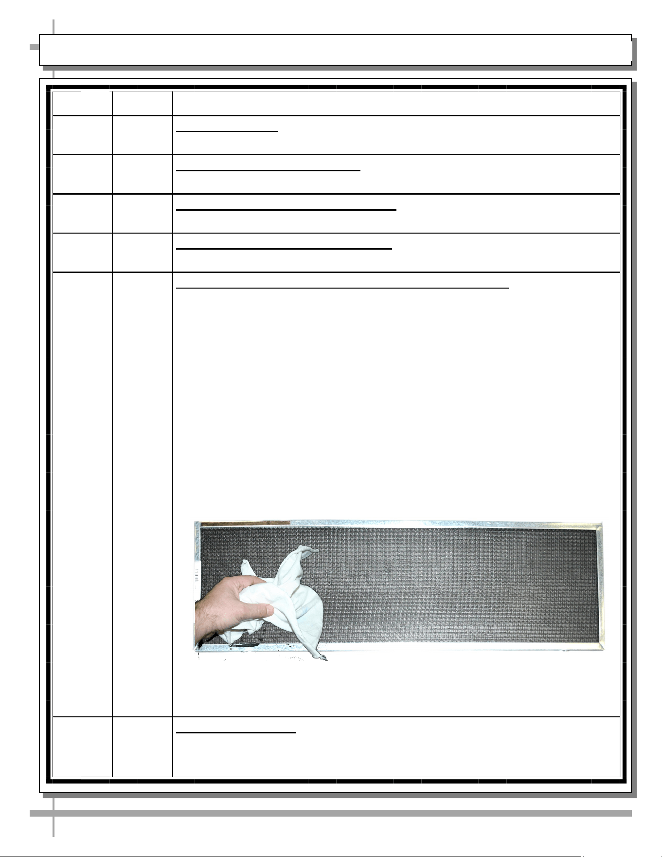
Weekly Magnetic Condenser Coil Filter (Self-Contained Units Only):
• This filter helps prevent dust particles from entering condenser coil.
• It is usually accessible at case rear.
• Clean magnetic condenser coil filter by following either step 1 or 2; then follow
step 3:
1. To clean by hand, (without using dishwasher), remove magnetic condenser
coil filter from case. Use a rag or soft-bristled brush to wipe off excess dust
particles from filter. Submerse in warm, soapy water. Use soft-bristled brush
to remove dust, dirt, grease and grime that may collect on filter. Rinse
thoroughly. Skip to step #3.
2. As magnetic condenser coil filter is dishwasher safe, remove from case
(no screw removal required) and use a rag or soft-bristled brush to wipe off
excess dust particles from filter. Run in normal dishwasher cycle. Remove
from dishwasher. Go to next step.
3. Dry with soft cloth or paper towel (as shown below) or allow to air dry.
Replace.
Monthly Under Case Cleaning: Remove front toe-kick (or rear panel). Vacuum under case
to remove all dust and dirt. Replace front toe-kick (or rear grille) when complete.
27
CLEANING SCHEDULE -STAINLESS STEEL: TO BE PERFORMED BY STORE PERSONNEL
General Stainless Steel Surface Cleaning (To Be Performed As Often As Needed):
• Certain grades of stainless steel, and some are more prone to corrosion than others.
• Stainless steel can become exposed to a wide variety of contaminants, which if left untreated can cause
stains and rust.
• Stainless steel requires a specific cleaning procedure to maintain its sheen and remain rust-free.
• Wash with a solution of liquid dishwashing detergent and hot water.
• Rinse with pure hot water from spray bottle. Wipe with clean sponge. This will remove soap residue
that can lodge in stainless steel’s microscopic grooves, causing rust.
• Dry with clean, soft cloth or paper towel.
• Caution! To prevent rust, you MUST rinse with pure hot water from a spray bottle while wiping with
clean sponge after EACH cleaning.
• Caution! Never clean with scouring powder or steel wool as they can mar, scratch and/or erode the
surface of stainless steel. When the surface properties of stainless steel have been compromised, rust
can form.
Brightening:
• Method 1: Brighten by polishing with a soft cloth or sponge with a solution of one part vinegar to 2 parts
water in a spray bottle.
• Method 2: Sprinkle baking soda on sponge and rub gently with soft cloth or sponge.
• Caution! To prevent rust, you MUST rinse with pure hot water from a spray bottle while wiping with
clean sponge after EACH cleaning.
• Dry with clean, soft cloth or paper towel.
Removing Streaks or Stains:
• Method 1: Place two teaspoons of rubbing alcohol on a microfiber cloth or pad. Rub the cloth along the
grain of the appliance until the entire area has been wiped. The rubbing alcohol will air dry itself.
• Method 2: Dip soft cloth or sponge in club soda and rub gently over area of concern.
• Caution! To prevent rust, you MUST rinse with pure hot water from a spray bottle while wiping with
clean sponge after EACH cleaning.
• Dry with clean, soft cloth or paper towel.
Polishing:
• Place a dab of olive oil onto clean soft cloth. Spread over area until a light sheen is observed. Use
pressure to “work the oil” into the small grooves in the surface. Apply firm, steady pressure using small
circular motions.
> Dry buff: Remove excess oil with clean cloth or paper towel using small circular motions.
> Wet buff: Use an ounce or white vinegar with clean cloth or paper towel using small circular motions.
> Continue wiping until oily finish has been removed.
• Caution! To prevent rust, you MUST rinse with pure hot water from a spray bottle while wiping with
clean sponge after EACH cleaning.
• Dry with clean, soft cloth or paper towel.
Removing Rust:
• If rust has begun to form, there are a variety of products that can treat it.
• Among these are CLR® (calcium, lime and rust remover) and Chemetall Oakite 33 (rust, oxides and
scale remover).
• Caution! To prevent food contamination, personal injury or further corrosion, carefully follow the
recommended cleaning precautions and instructions.
PREVENTIVE MAINTENANCE - TO BE PERFORMED BY TRAINED SERVICE PROVIDERS ONLY
28
PREVENTIVE
MAINTENANCE
FREQ. INSTRUCTIONS
Case Exterior Quarterly Condensing Coil:
• Remove rear grille to access area. Simply lift up and off.
• Roll/slide out condenser package. Note: At initial slide-out, it may be
necessary to remove two (2) compressor pan shipment screws to slide it
out from under case.
• Warning! Coil fins are sharp. Handle with care!
• Caution! Airborne dust can contaminate food! Use wet rags to cover
area where air pressure is blowing.
• Use air pressure or industrial strength vacuum; clean dust and dirt that
may collect on condenser coil.
• Slide/roll condensing package back under case.
• Return rear grille to case.
Quarterly Under Case Cleaning:
Once refrigeration package is clear of unit, vacuum under case to remove all
dust and dirt that collects under case.
Quarterly Rear Sliding Doors:
• Rear sliding doors can become loose, sloppy or dislodge from their door
tracks. Doors could eventually FALL OUT of the door frames and into (or
out of) the case causing damage or injury.
• Bottom door guides may have become worn and need to be replaced.
• Contact Structural Concepts’ Technical Service for guidance and/or
replacement parts information. See last page of manual for contact info.
Case Interior Quarterly Tub, Coil, Drain, Evaporator Fans, Brackets:
• Remove decking.
• Use vacuum to clean entire area.
• After vacuuming, clean area with warm water, clean cloth, and mild soap
solution.
• Remove any debris that may clog drain.
Quarterly Honeycomb: Check honeycomb air diffuser to determine whether it is dirty. If
dirty, remove from case. Clean with mild detergent. Rinse with high-pressure
sprayer. Dry. Return to case.
Quarterly Refrigeration Package/Compressor Area (Self-Contained Units Only):
Caution! Be certain to disconnect power from case before cleaning
refrigeration package!
• Warning! Overflow condensate pan Is HOT! Disconnect power from case
and allow to cool before cleaning evaporator pan!
• Slide/roll compressor package out from under case.
• Use a scrub-brush and a de-scaling solution such as CLR® (to prevent
corrosion, lime and rust). Follow instructions as to proper dilution, safety
precautions and scrubbing method.
• After thoroughly cleaning pan with scrub-brush and solution, rinse
thoroughly with clean water (in spray bottle) and wipe dry with sponge or
paper towel.
• Use moist cloth to wipe off dust & debris that collects on various parts
(fans, sight glass, overflow pan, etc.).
• Slide refrigeration assembly back under case.
• Replace front panel and lower grille via hooks (no screws required).
WARNING! TURN OFF CASE BEFORE PERFORMING PREVENTIVE MAINTENANCE!
29
TROUBLESHOOTING - TO BE PERFORMED BY STORE PERSONNEL (UNLESS NOTED OTHERWISE)
CONDITION TROUBLESHOOTING
Ice Is Forming on
Evaporator Coils
Perform extended manual defrost weekly. See CLEANING SCHEDULE - TO BE
PERFORMED BY STORE PERSONNEL section in manual for additional info.
Product Is Drying
Out
Trained Service Providers Only: Check the relative humidity in the store.
Water Is On Floor Trained Service Providers Only: Check that the drain trap is free of debris.
Check that the drain hose is correctly positioned over hot gas condensate pan.
Trained Service Providers Only: Check store conditions.
• To prevent condensation in NSF/ANSI Type I environments, maximum conditions
are to be 55% relative humidity / 75° Fahrenheit.
• For NSF/ANSI Type II environments, maximum conditions are to be 55% relative
humidity / 80° Fahrenheit.
• If you are unsure if your unit is classified as NSF/ANSI Type I or Type II, see tag
next to serial label on your case.
Fan Emits
Excessive Noise
Trained Service Providers Only: Check that the case is aligned, level and plumb.
Trained Service Providers Only: Check evaporator fan for cleanliness.
Trained Service Providers Only: Unplug/power off fan motors. Check motor shaft for
bearing wear.
Trained Service Providers Only: Check that fan motors are securely mounted in
brackets.
Trained Service Providers Only: Verify that fan blades are securely mounted to fan
motor.
Trained Service Providers Only: Check that nothing is preventing blade rotation.
Trained Service Providers Only: Check that the fan shroud is properly secured.
Fans Not Working Check that the MAIN power switch is on.
Trained Service Providers Only: Check that fans are plugged in at the fan shroud.
Trained Service Providers Only: Check for foreign material obstructing fan
performance.
Trained Service Providers Only: Check that fan blades freely rotate within fan
shrouds.
Trained Service Providers Only: Check that power is going to fans.
Trained Service Providers Only: Check that fan wiring is connected on terminal blocks
Digital Control
Display Is Blank
Check that the MAIN power switch is on.
Trained Service Providers Only: Check the circuit breaker box for tripped circuits.
System Not
Operating
Trained Service Providers Only: Check that the utility power is on.
Check that the MAIN power switch is on.
Trained Service Providers Only: Check the circuit breaker box for tripped circuits.
30
TROUBLESHOOTING - TO BE PERFORMED BY STORE PERSONNEL (UNLESS NOTED OTHERWISE)
CONDITION TROUBLESHOOTING
Case Lights Not Working Check that light switch has been flipped on.
Check bulbs for proper installation and connection.
Check for burned out bulbs.
Clean dirt and dust from the bulbs to prevent flickering.
Not Holding Temperature If a large amount of warm product was added to the case, it will take time for
the temperature to adjust. Unit needs product to be pre-chilled.
Temperature changes during defrost mode but will return to normal. Fourth
LED will indicate defrost cycle in progress.
Check that case is not in sun or near a heat or air-conditioning vent.
If case is located near outside doors, temperature fluctuation can hinder unit’s
ability to maintain temperature.
Check that condenser coil has been cleaned.
Check air return grilles for obstructions.
Trained Service Providers Only: Check sight glass for flashing and/or low
charge.
Trained Service Providers Only: Check set point temperature; it may be
adjusted too high.
Condensing Unit Is Not
Operating
Check that the power is turned on.
Determine if temperature controller settings are properly set. See your case’s
serial label for your model’s specified settings. See SERIAL LABEL
LOCATION & INFORMATION LISTED / TECH INFO & SERVICE section in
manual for label location, etc.
31
TROUBLESHOOTING - CONDENSING SYSTEM (BY TRAINED SERVICE PROVIDERS ONLY)
CONDITION TROUBLESHOOTING
Head Pressure Too High Check that the condensing coil is not dirty or covered.
Check that condensing fans are working.
Check that refrigerant is not overcharged.
Perform sub-cooling check and verify that no contaminates are in system.
Check that liquid line filter dryer is not plugged.
Check that close-offs are intact (around condensing coil) and that air is not
recirculating.
Check that store ambient temperature isn’t above maximum allowed.
• See OVERVIEW / TYPE / COMPLIANCE / WARNINGS /
PRECAUTIONS / WIRING / PLUGS section in this manual.
Head Pressure Too Low Check if sight glass is flashing or showing low charge.
Check that suction pressure isn’t too low.
Check that compressor reed valves aren’t bad. Look for high suction/low
head pressure. Perform pump-down.
32
TROUBLESHOOTING - EVAPORATOR SYSTEM (BY TRAINED SERVICE PROVIDERS ONLY)
CONDITION TROUBLESHOOTING
Low Suction Pressure Check if sight glass is flashing or showing low charge.
Check that expansion valve (TXV) isn’t restricted. Check element charge.
Check that liquid line or filter isn’t restricted. Check that refrigeration lines
and/or hoses are not kinked on either high or low sides.
Check that evaporator fan motors are working.
Check that superheat is between 6 °F to 8 °F.
Check that there is no air recirculation around evaporator coil.
Check that evaporator coil is not iced up.
High Suction Pressure Check for refrigerant overcharge.
Check that compressor reed valves aren’t bad. Look for high suction/low
head pressure. Perform pump-down.
Check that the “cooling load” isn’t high. Product must be pre-chilled before
placing in refrigerated section of case.
Check that case is at least 15-feet from exterior doors, overhead HVAC
vents or any air curtain disruption.
Check that unit is not exposed to direct sunlight via windows or any other
heat source (ovens, fryers, etc.).
Check that superheat adjustment isn’t low.
Check TXV bulb installation
a. Poor thermal contact.
b. Warm location.
33
SERIAL LABEL LOCATION & INFO LISTED / TECH INFO & SERVICE / REFRIGERATED CASES ONLY
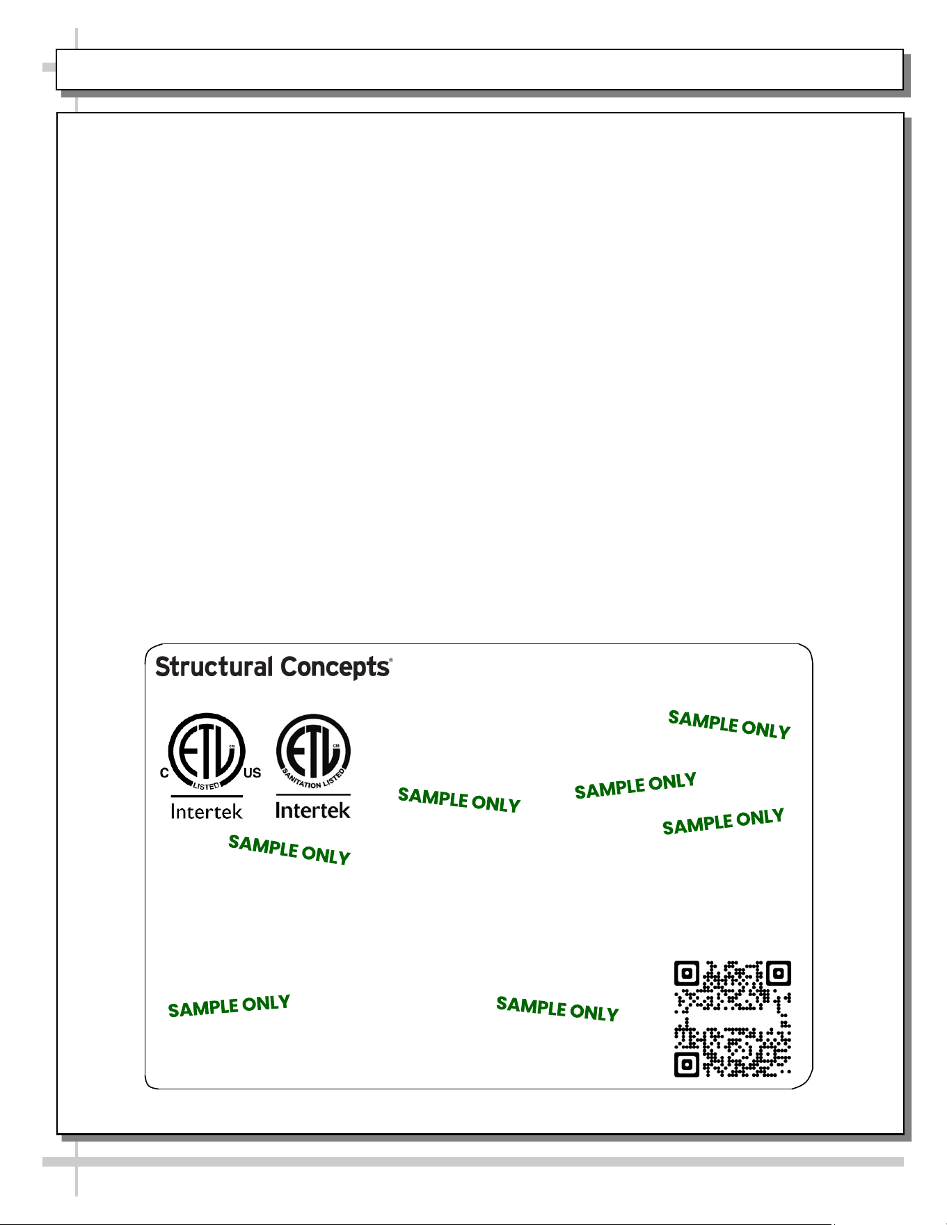
--- Sample Serial Label For Refrigerated Cases ---
MODEL NRS3648RXV-SAMPLE
SERIAL NO. 12345X30DZ098765
888 E. Porter Rd - Muskegon, MI 49441
3048256
Conforms to UL Std. 471
Conforms to NSF/ANSI Stds. 2 & 7
CERTIFIED TO CAN/CSA
STD C22.2 NO 120
ELECTRICAL RATING
REFRIGERANT
DESIGN PRESSURE
MINIMUM CIRCUIT AMPACITY
MAXIMUM OVERCURRENT
120/1/60 16 A
R513A AMOUNT 50 OZ
HIGH 186 LOW 88
20A
20A
Super Heat Temp 6-8 °F FOR PARTS AND SERVICE
Defrost 6 defrosts per day, 45 °F CALL 1-800-433-9490
Serial Label Location & Information Listed /
Technical Information & Service
• Serial labels are affixed at a wide range of places
(on the header, near thermostat, at case rear,
behind panels/toe-kicks, on electrical boxes, etc.).
• Serial labels contain electrical, temperature and
refrigeration information, as well as regulatory
standards to which the case conforms.
• Sample serial label shown below.
• For additional technical information and service, see
the TECHNICAL SERVICE page in this manual for
instructions on contacting Structural Concepts’
Technical Service Department.
Fusion
Sample QR Code
SCAN FOR PRODUCT LITERATURE
SAMPLE ONLY
SAMPLE ONLY
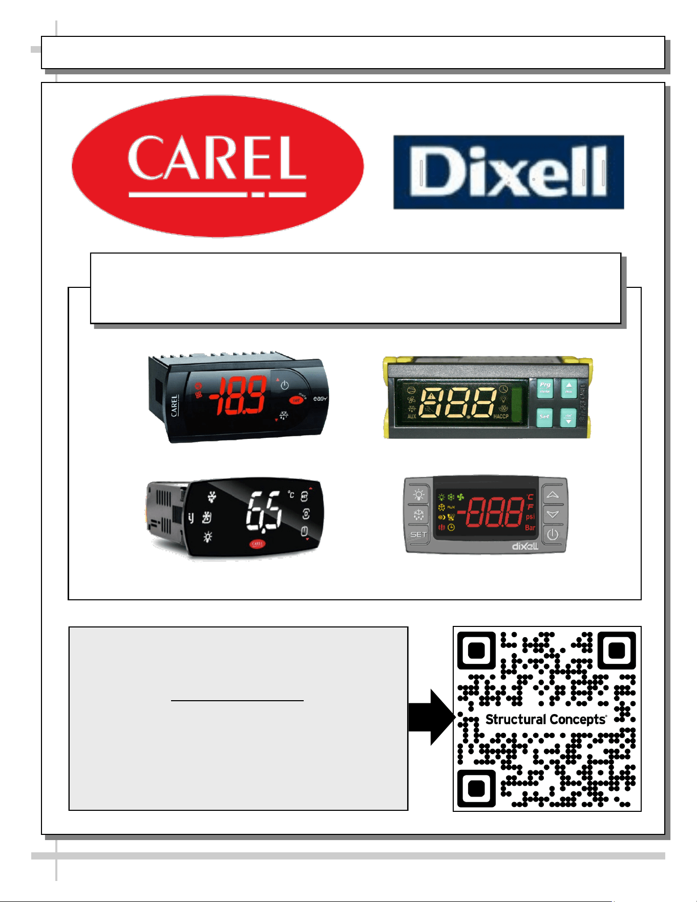
PROGRAMMABLE CONTROLLER (SELECT, CLICK ON OR SCAN QR CODE FOR INFORMATION)
34
Carel® iJF Platform
Carel® PJEZ Platform
Carel® ir33 Platform
Dixell® XM670K-XM679K Platform
To Access Information About The Programmable
Controller That Is Used On Your Case,
Follow These Instructions:
> If Viewing This Document on Smart Phone, Tablet
or Computer, Select/Click On The QR Code at Right.
> If Viewing This Document In Print (Hard Copy),
Scan The QR Code at Right With Your Smart Phone
or Tablet.
Determine Which Programmable Controller Is On Your Case (Controllers
That Are Commonly Used By Structural Concepts Are Shown Below).
Your Particular Programmable Controller May Differ.
STRUCTURAL CONCEPTS TECHNICAL SERVICE CONTACT INFORMATION & LIMITED WARRANTY
35
TECH SERVICE/WARRANTY CONTACT INFO:
1 (800) 433-9490 / EXTENSION 1
DAYS/HOURS AVAILABLE:
MONDAY - FRIDAY (CLOSED HOLIDAYS)
8:00 A.M. to 8:00 P.M. EST
YOU MUST HAVE THE FOLLOWING INFO AVAILABLE
BEFORE CONTACTING STRUCTURAL CONCEPTS:
SERIAL NO. / MODEL NO. / STORE NO. / STORE
ADDRESS / DETAILS (PHOTOS, LEAK LOCATIONS,
DAMAGE, STORE’S AMBIENT CONDITIONS, ETC.)
To Access The Limited Warranty To Your
Case, Follow These Instructions:
> If Viewing This Document on Smart Phone,
Tablet or Computer, Select/Click On The QR
Code at Right.
> If Viewing This Document In Print (Hard
Copy), Scan The QR Code at Right With Your
Smart Phone or Tablet.