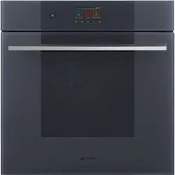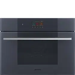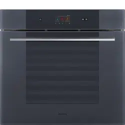
IMPORTANT SAFETY INSTRUCTIONS READ CAREFULLY AND914780213/B
e
IMPORTANT SAFETY INSTRUCTIONS
READ CAREFULLY AND KEEP FOR FUTURE REFERENCE
Recognize safety information
The safety messages will inform you of
potential hazards, how to avoid the risk of
injury and what can occur if the instructions
are not followed.
Important Notes to the Installer
• Read all instructions contained in these
installation instructions before installing
the appliance.
• Remove all packaging material from the
appliance compartments before
connecting.
• Observe all governing codes and
prescriptions.
• Leave these instructions with the
consumer.
Important Notes to the
Customer
• Keep these instructions with your
Owner's Guide for the local electrical
inspector's use and future reference.
WARNING: If the instructions contained in this manual are not followed
exactly, fire or shock may result causing property damage, personal
injury or death.
INSTALLER: Leave these installation instructions with the appliance for
the owner.
OWNER: Please retain these instructions for future reference and pass
them on to any future user.
IMPORTANT: Save these instructions for the local electrical inspector’s
use.
NOTICE: This appliance must be installed solely and exclusively by a
qualified technician. Any technical procedures must be carried out by
an authorized technician.
READ AND SAVE THESE INSTRUCTIONS
WARNING
• This indicates that death or serious
injuries may occur as a result of non-
observance of this warning.
CAUTION
• This indicates that minor or moderate
injuries may occur as a result of non-
observance of this warning.
NOTES
• This indicates important information
and/or suggestion.
4 - IMPORTANT SAFETY INSTRUCTIONS READ CAREFULLY 914780213/B
• Proper installation is your responsibility.
Have a qualified technician install and
ground this appliance in accordance
with these installation instructions.
• It is the responsibility of the installer to
comply with installation information
specified on the model/serial ID plate.
The ID plates are visibly located on the
appliance. These ID plates must never
be removed.
• ELECTRICAL GROUNDING
REQUIRED: See the “Electrical
connections” section. It is the customer’s
responsibility to contact a qualified
electrician to install the appliance.
• Ensure that the electrical system is
adequate and conforms with the
national ANSI / NFPA 70 ELECTRICAL
CODE - latest edition - or the
CANADIAN ELECTRICAL CODE,
C22.11 - 1 and C22.2 No. 01982 - or
latest edition - and all local prescriptions
and regulations.
• IMPORTANT: Observe all governing
codes and prescriptions.
Electrical safety
• This appliance must be grounded.
• If required by the National Electrical
Code (or Canadian Electrical Code),
this appliance must be installed on a
separate branch circuit. Failure to follow
these instructions can result in death, fire,
or electrical shock.
• For appliances equipped with a cord
and plug, do not cut or remove the
ground prong. It must be plugged into a
matching grounding type receptacle to
avoid electrical shock. If there is any
doubt as to whether the wall receptacle
is properly grounded, the customer
should have it checked by a qualified
electrician.
CAUTION
• This appliance is NOT designed for
installation in manufactured (mobile)
homes, on a boat or in recreational
vehicles (RVs).
• DO NOT install this appliance
outdoors.
• This unit is designed as a cooking
appliance. For safety purposes, never
use it for warming the room or as a
space heater.
WARNING
• Never allow children to play with
packaging material.
• DO NOT modify or alter the
construction of the appliance.
• Do not store or use gasoline or other
flammable vapors, liquids or materials
near this or any other appliance.
• Do not step, lean or sit on the door
appliance, it can result in serious injuries
and cause damage to the appliance.
• Make sure your appliance is properly
installed and grounded by a qualified
technician. Installation, electrical
connections and grounding must
comply with all applicable codes.
WARNING
Electrical shock hazard
• Personal injury or death from electrical
shock may occur if the appliance is not
installed by a qualified installer or
electrician.
• Before installing, turn power OFF at the
service panel. Lock service panel to
prevent power from being turned ON
accidentally.
• Do not use an extension cord to
connect this appliance.
• Do not use an adapter.
• Do not use a gas supply line for
grounding the appliance.
Failure to follow the above instruction
could result in death, fire, or electrical
shock.
ELECTRICAL CONNECTION - 5914780213/B
e
• INSTALLER - show the owner the
location of the circuit breaker or fuse.
• Make sure that all the appliance
controls are in the OFF position before
plugging the electrical cord into an
outlet.
Safety codes and standards
This appliance complies with the latest
version of one or more of the following
standards:
• CAN/CSA C22.2 No. 150 -
Microwave Ovens
• CSA E60335-2- 25 - Microwave
Ovens
• CAN/CSA C22.2 No 61 - Household
Cooking Appliances
• CSA C22.2 No. 64 - Household
Cooking and Liquid
• UL 1026 - Electric Household Cooking
and Food Serving Appliances
• UL 923 - Microwave Cooking
Appliances
• UL 858 - Household Electric Appliances
It is the responsibility of the owner and the
installer to determine if additional
requirements and/or standards apply
to specific installations.
Proposition 65 Warning
This product may contain a chemical known
to the State of California, which can cause
cancer or reproductive harm. Therefore, the
packaging of your product may bear the
following label as required by California:
ID plate position
Make sure that power line rating matches
the specifications indicated on the ID plate.
The ID plates are visibly located on the
appliance.
ELECTRICAL CONNECTION
WARNING
State of California propositions 65
Warning
• Cancer or Reproductive Harm
More informations:
www.P65Warnings.ca.gov
NOTES
• The ID plates must never be removed.
WARNING
Electrical shock hazard
• Electrical ground is required on this
appliance.
• Do not connect to the electrical supply
until the appliance is permanently
grounded.
Failure to follow the above instruction
could result in death, fire, or electrical
shock.
• Do not use an extension cord to
connect this appliance.
• Do not use a gas supply line for
grounding the appliance.
• Do not use an adapter.
WARNING
Electrical shock hazard
Failure to follow the above instruction
could result in death, fire, or electrical
shock.
6 - ELECTRICAL CONNECTION 914780213/B
Frame grounded by connection of
grounding wire to neutral wire. If used in the
new branch circuit installation (1996 NEC)
or if local codes do not permit grounding
through neutral wire, open the connection
and use the grounding wire to the ground
unit in compliance with local codes.
Connect the neutral wire to the branch
circuit’s neutral conductor in the usual
manner:
• Disconnect the ground from the neutral
at the free end of the conduit.
• Use the grounding terminal or lead to
ground the unit.
• Connect the neutral terminal or wire to
the branch circuit neutral in the usual
manner.
U.S. Installation only / 3-wire
branch circuit
See diagram. Where local codes allow the
connection of the ground wire from the
oven to the power supply cable neutral
wire (white wire):
• The ground wire must be connected first;
• If local codes permit, connect the green
or yellow-green ground wire from the
appliance and the white wire from the
appliance to the power supply neutral
wire (white wire).
• Connect the red and black leads from
the appliance to the matching color
wires in the junction box using UL/CSA
listed wire connectors.
U.S. and Canada Installation only
/ 4-wire branch circuit
• Separate the green or yellow-green
wires from the white wires that extend
out of the end of the appliance cable.
• The ground wire must be connected first;
• Connect the green or yellow-green
ground wire from the appliance to the
ground wire in the junction box (green
colored wire) using UL/CSA listed wire
connectors. Do not connect the
grounding wire to the neutral wire in the
• Do not over bend the flexible conduit to
avoid the exposures of internal wires.
• Do not use an extension cord to
connect this appliance.
WARNING
• DO NOT modify or alter the
construction of the appliance.
• Make sure your appliance is properly
installed and grounded by a qualified
technician. Installation, electrical
connections and grounding must
comply with all applicable codes.
CAUTION
Any local codes or ordinances should be
give priority over these instructions.
WARNING
Electrical shock hazard
Failure to follow the above instruction
could result in death, fire, or electrical
shock.
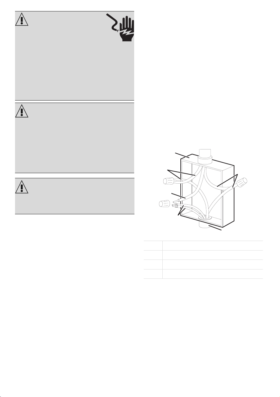
A cable from power supply
B junction box
C cable from appliance
D UL/CSA listed conduit connector
A
B
rw
bw
ww
gw
C
D
CABINET INSTALLATION - 7914780213/B
e
junction box.
• Connect the red and black leads from
the appliance to the matching color
wires in the junction box using UL/CSA
listed wire connectors.
• Connect the white wire from the
appliance to the neutral white wire in the
junction box using a UL/CSA listed wire
connect.
• Connect to a 20 A fuse or circuit
breaker. Connect to copper wire, or, if
connection is made to aluminum house
wiring, use UL-listed or CSA-approved
connectors approved for joining
aluminum and copper wiring.
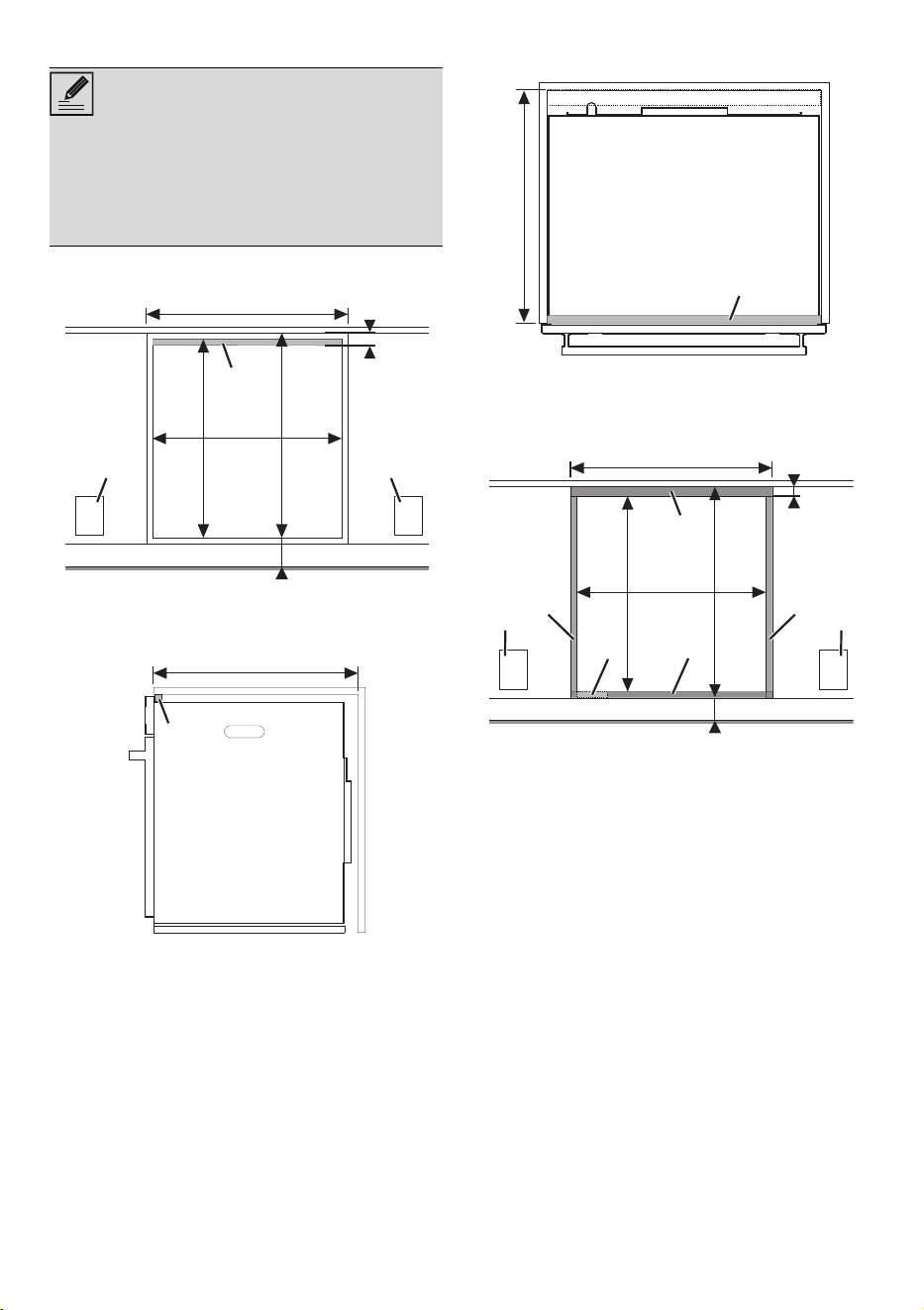
CABINET INSTALLATION
Unpacking, moving and
positioning the appliance
• Unit is heavy and requires at least two
people or proper equipment to move.
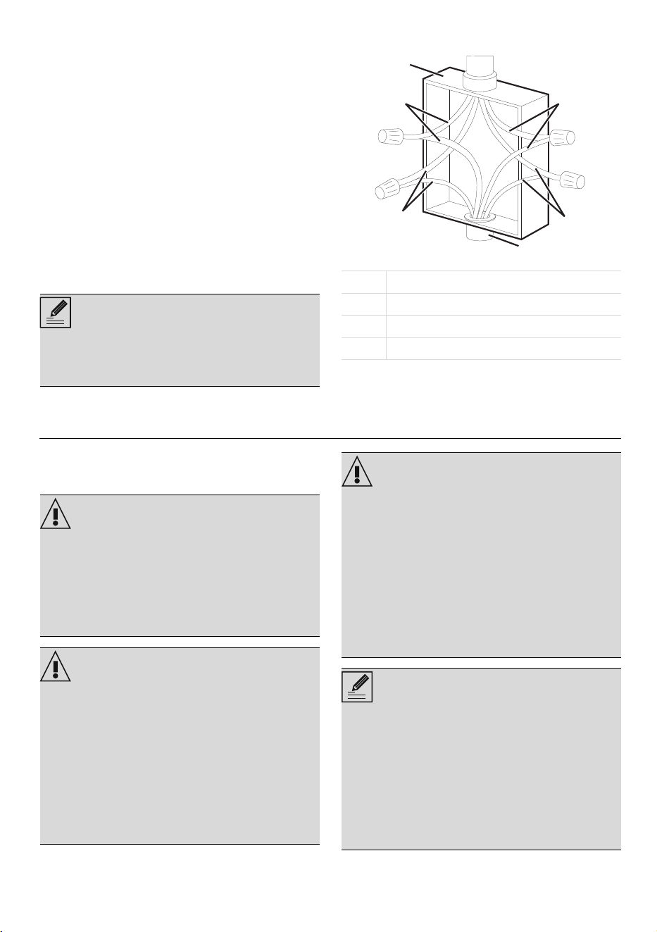
NOTES
• Both leads coming out of the appliance
must be connected according to the
diagrams shown in figures.
bw black wires
gw green or yellow-green wires
rw red wires
ww white wires
A
B
rw
gw
ww
bw
CD
WARNING
Heavy appliance, danger of
crushing injuries.
• Position the appliance into the cabinet
cutout with at least two person.
• Failure to do so can result in injury or
damage to the unit.
WARNING
Pressure on the open door
Risk of damages to the appliance
• When positioning the appliance during
installation, do not use the door handle
to lift or move this appliance.
• Never use the oven door to lever the
appliance into place when fitting.
• Avoid exerting too much pressure on
the oven door when the door is open.
CAUTION
• Wear protective gloves to avoid cutting
fingers on sharp edges during
installation.
• Do not lift the appliance by holding the
upper heating element.
• Cabinet materials must withstand a
temperature of at least 195°F (90°C).
• The appliance support surface must be
solid, level and flat.
NOTES
• This appliance is intended to be built-in
to a cabinet structure only and is not
intended for attachment to the building
structure.
• For microwave appliances: the
instructions shall state that the appliance
must be operated with any cabinet
door open.
8 - CABINET INSTALLATION 914780213/B
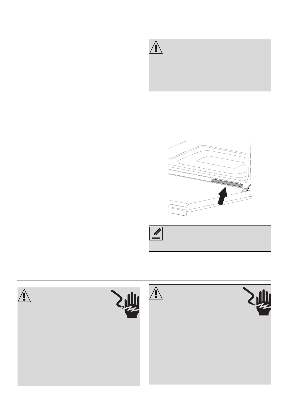
• Remove the outer carton and packing
material from the shipping base.
• Due to its weight, a dolly/fork lift with
soft rubber tread wheels should be used
to move this unit. The weight must be
supported uniformly across the bottom.
• To avoid damage to the floor, place the
appliance on cardboard prior to
installation. Do not lift by the door
handle or any part of the frame or trim.
• Use the handles at the side to lift the
appliance.
• Remove the door for easier handling
and installation (not for speed or
microwave appliances).
• Remove the shipping materials and tape
from the oven.
• Remove the literature contained in the
package.
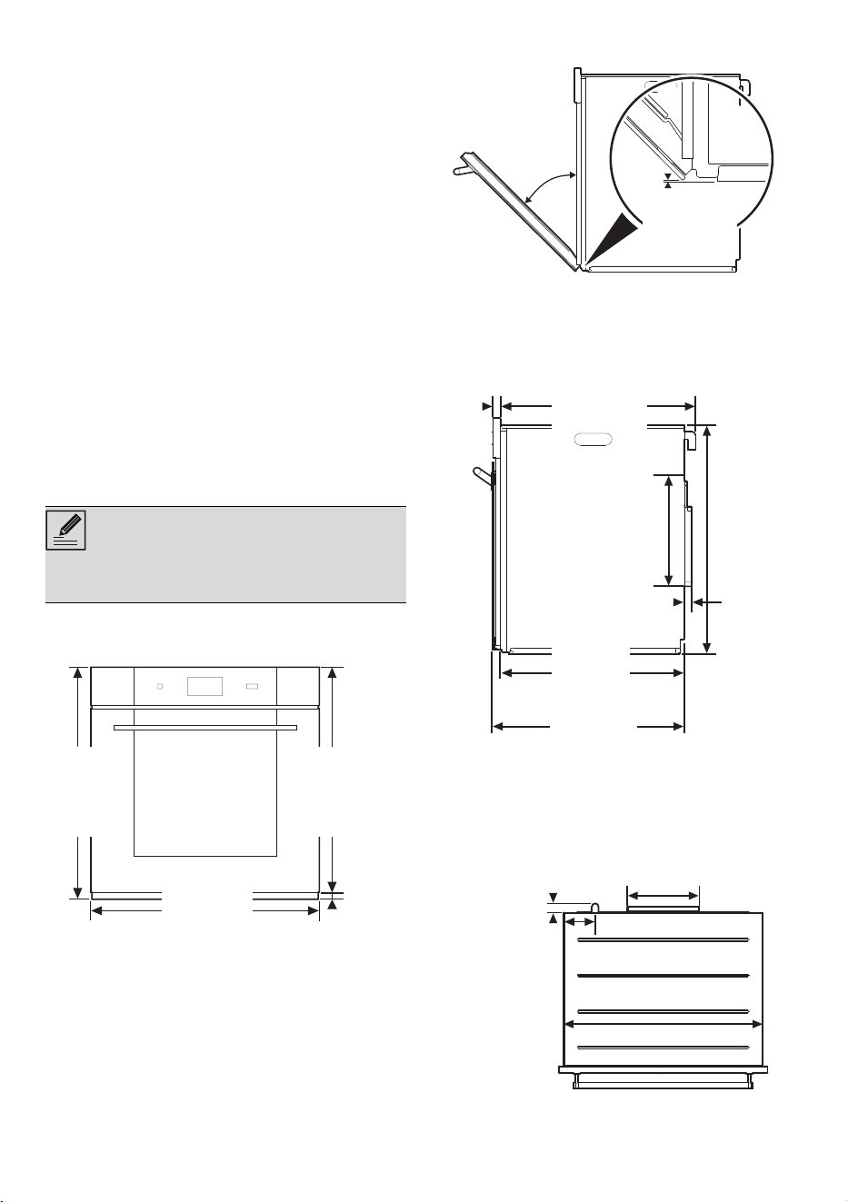
Ventilation recommendations
Appliance overall dimensions
(front view)
(side view)
(side view)
(top view)
NOTES
• Do not obstruct air vents or heat vent
openings.
754 mm
"29 /
11
16
"
754 mm
"29 /
11
16
"
754 mm
"29 /
11
16
"
710 mm
"
27 /
15
16
"
754 mm
"
29 /
11
16
"
698 mm
"
27 /
1
2
"
12 mm
"
/
1
2
"
1mm
0.04"
45°
587 mm587 mm
23 / "
1
8
23 / "
1
8
556 mm
"21 /
7
8
"
579 mm
"22 /
13
16
"
23 mm23 mm
/"
15
16
/"
15
16
691 mm691 mm
27 / "
3
16
27 / "
3
16
317 mm317 mm
12 / "
1
2
12 / "
1
2
23 mm23 mm
/"
14
16
/"
14
16
34 mm34 mm
1/"
5
16
1/"
5
16
260 mm260 mm
10 / "
1
4
10 / "
1
4
114 mm114 mm
4/"
1
2
4/"
1
2
722 mm722 mm
28 / "
7
16
28 / "
7
16
CABINET INSTALLATION - 9914780213/B
e
(side view)
Power cord position
(back view)
Fix the appliance to the unit
Fix the appliance to the unit by screwing the
4 screws with their washers into the holes in
the frame.
Mounting into a column
565 mm565 mm
22 / "
1
4
22 / "
1
4
615 mm615 mm
24 / "
3
16
24 / "
3
16
114 mm114 mm
4/"
7
16
4/"
7
16
73 mm73 mm
2/"
7
8
2/"
7
8
NOTES
• If the cutout height is 27 15/16"
(710 mm) it's necessary to install the
special lifting kit (to be purchased
separately) under the appliance.
NOTES
• *Make sure that the carcase rear/
bottom section has an opening approx.
2 3/8" (60 mm) deep.
1/
3
8
1/
3
8
- 1 /
9
16
- 1 /
9
16
35-40 mm35-40 mm
min. 610 mmmin. 610 mm
min. 24"min. 24"
60 mm60 mm
2/"
3
8
2/"
3
8
10 - CABINET INSTALLATION 914780213/B
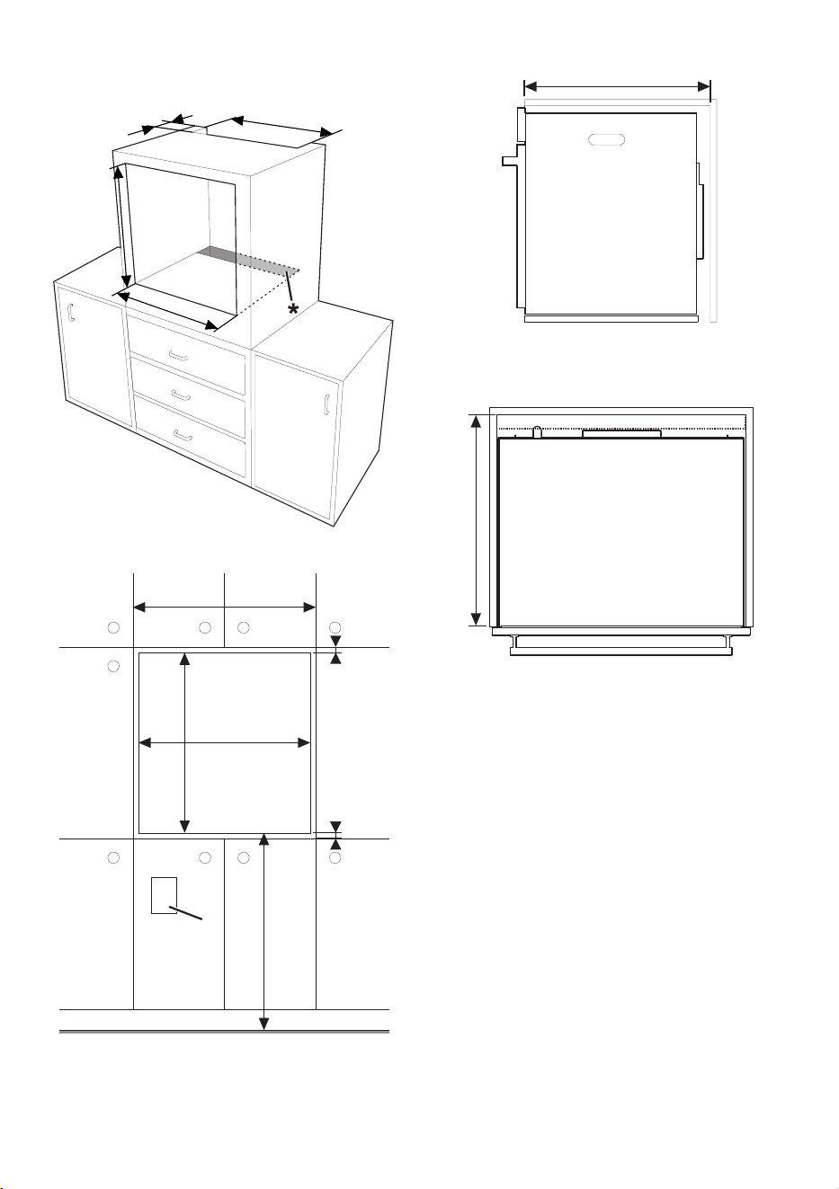
(front view)
(side view)
(top view)
35-40 mm35-40 mm
1 / "-1 / "
39
816
1 / "-1 / "
39
816
600-700 mm600-700 mm
23 / "-27 / "
59
816
23 / "-27 / "
59
816
695 mm695 mm
27/"
3
8
27/"
3
8
724 mm724 mm
28/"
1
2
28/"
1
2
B
F
C
C
D
AA
C
i
b
F
E
AA
B
GG
GG
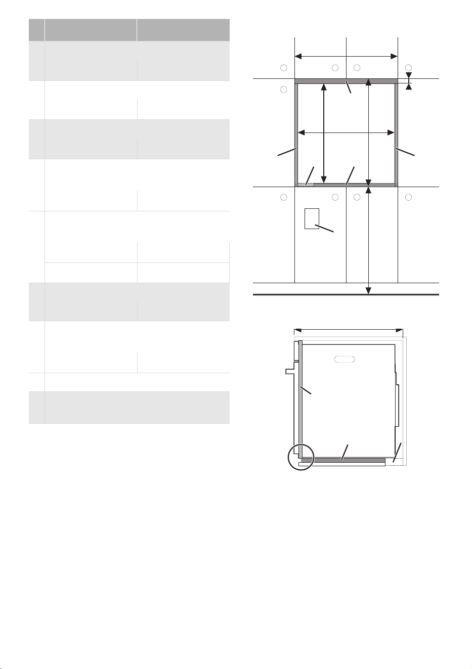
CABINET INSTALLATION - 11914780213/B
e
Under-counter installation
in mm
A Width of cabinet
min. 29
13
/
16
min. 758
BWidth of cutout
29
1
/
2
724
C Height of cutout
27
3
/
8
- 27
15
/
16
695 - 710
D Top of cutout to bottom of upper
cabinet
3
/
8
-
7
/
16
9 - 11
E Top of cutout to top of lower cabinet
door
min.
3
/
16
min. 5
F Bottom of cutout to floor
(recommended)
min. 4
1
/
2
min. 114
max. 34
5
/
8
max. 880
G Depth of cutout
min. 24 min. 610
H Bottom of countertop to bottom of
cutout
min. 28
1
/
16
min. 712
jb Recommended junction box
NOTES
• *Make sure that the carcase rear/
bottom section has an opening approx.
2 3/8" (60 mm) deep.
• If the cutout height is 27 15/16" (710
mm) it's necessary to install the special
lifting kit (to be purchased separately)
under the appliance.
724 mm724 mm
28/"
1
2
28/"
1
2
695 mm695 mm
27/"
3
8
27/"
3
8
8-10mm
57
/-/"
16 16
min. 2mm
min. / "
1
16
min. 610mmmin. 610mm
min. 24"min. 24"
21 / "
5
8
21 / "
5
8
550 mm550 mm
2/"
3
8
2/"
3
8
60 mm60 mm
12 - CABINET INSTALLATION 914780213/B
(front view)
(side view)
(top view)
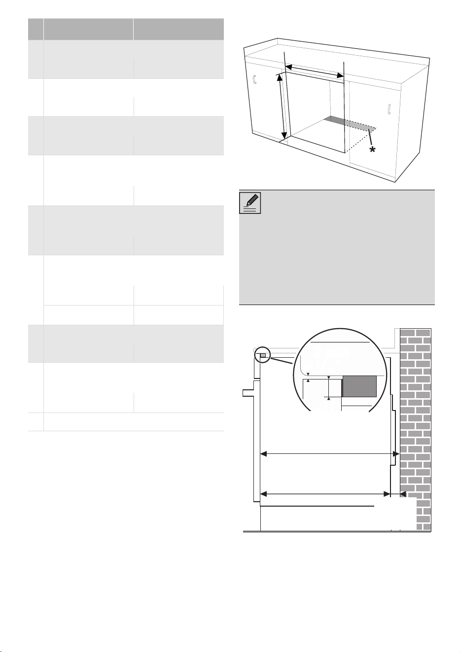
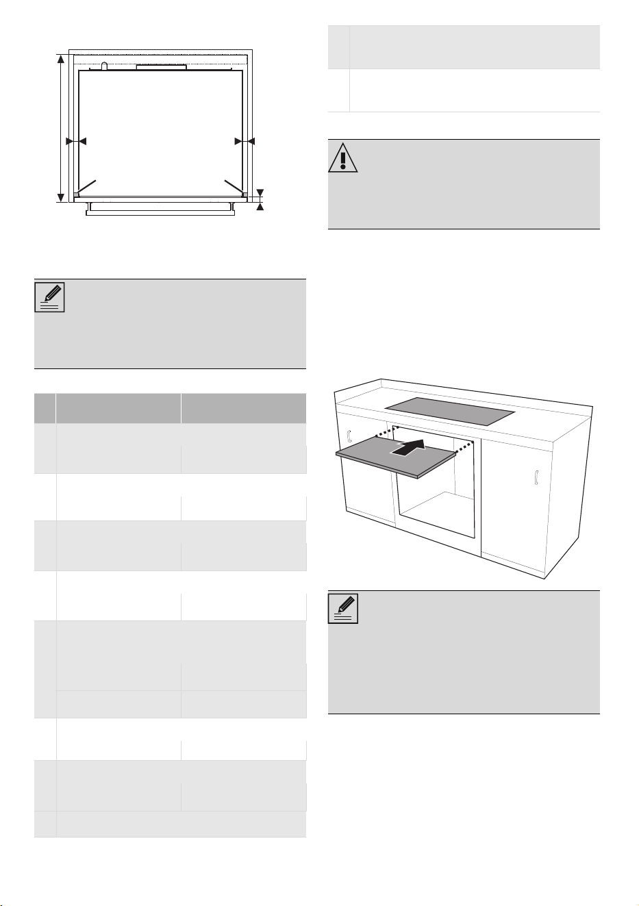
Flush installation
Under countertop mounting (front view)
NOTES
• If the appliance is to be built-in under a
worktop, a wooden bar has to be
installed to use the seal that is glued to
the back of the front panel, to prevent
water or other liquids from leaking in.
F
B
H
C
AA
C
H
B
i
b
i
b
wb
D
F
GG
wb
GG
wb
BB
HHC
sc
i
b
sc
i
b
CH
tc
D
B
F
AA
pp
coco
CABINET INSTALLATION - 13914780213/B
e
Mounting into a column (front view)
(side view)
in mm
A Width of cabinet
min. 29
13
/
16
min. 758
BWidth of cutout
29
1
/
2
724
C Height of cutout
27
3
/
8
- 27
15
/
16
695 - 710
D Top of cutout to bottom of upper cabi-
net door
min.
11
/
16
min. 17
F Bottom of cutout to floor (recom-
mended)
min. 4
1
/
2
min. 114
max. 34
5
/
8
max. 880
G Depth of cutout
min. 24 min. 610
H Bottom of countertop to bottom of cut-
out
min. 28
1
/
16
min. 712
jb Recommended junction box location
wb Wooden bar (recommended)
pp
H
C
FF
b
sc sc
BB
H
D
tc
AA
C
i
coco
sc
GG
coco
pp
14 - CABINET INSTALLATION 914780213/B
(top view)
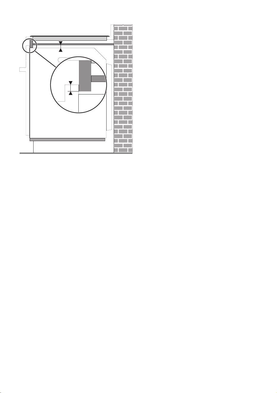
Built-in under hob
Whenever a hob is installed above the
oven, a wooden separator has to be
installed at a minimum distance of 3/4" -
20 mm from the top of the oven to prevent
overheating when the two appliances are
used at the same time. It must only be
possible to remove the separator by using
suitable tools.
NOTES
• Cleats and platform must be recessed
5/8” (16 mm) from the front of the
cabinet.
in mm
A Width of flush inset cutout
min. 29
13
/
16
min. 758
B Width of opening
28
9
/
16
726
C Height of opening
27
3
/
8
- 27
15
/
16
695 - 710
D Height of top cleat (tc)
min.
11
/
16
min. 17
F Bottom of cutout to
floor (recommended)
min. 4
1
/
2
min. 114
max. 34
5
/
8
max. 880
GDepth of cutout
min. 24 min. 610
H Height of flush inset cutout
min. 28
1
/
16
min. 712
jb Recommended junction box location
sc sc
/"
15
16
/"
15
16
24 mm24 mm
/"
5
8
/"
5
8
16 mm16 mm
GG
/"
5
8
/"
5
8
16 mm16 mm
sc
Side Cleat 16 mm -
5
/
8
tc Top Cleat
WARNING
• Check the hob installation manual to
comply with all required safety
clearances.
NOTES
• When using a wooden separator, a
wooden bar has to be installed under
the worktop in order to use the seal that
is glued to the back of the front panel to
prevent water or other liquids leaking in.
CABINET INSTALLATION - 15914780213/B
e
min 20 mmmin 20 mm
8-10 mm8-10 mm
57
/-/"
16 16
57
/-/"
16 16
min / "
3
4
min / "
3
4