CUB CADET LLC, P.O. BOX 361131 CLEVELAND, OHIO 44136-0019
Printed In USA
Illustrated Parts Manual
Cub Garden Tractors
Form No. 769-09535
November 19, 2013
2
To The Owner
Record Product Information
To ease in ordering replacement parts, please locate the model
plate on the equipment and record the information in the
provided area to the right. You can locate the model plate by
looking beneath the seat.
Model NuMber
Serial NuMber
Table of Contents
Painted Parts
When ordering painted service parts, a four digit color suffix must be added to the part number (e.g. 783-XXXXX-0637).
Please refer to the table below for current color codes:
Thank you for purchasing a Cub Cadet Garden Tractor. It was
carefully engineered to provide excellent performance when
properly operated and maintained.
All information in this manual is relative to the most recent
product information available at the time of printing. Please be
aware that this Illustrated Part’s Manual may cover a range of
product specifications for various models.
Components listed and/or illustrated in this manual may not be
applicable to all models. We reserve the right to change product
specifications, designs and equipment without notice and
without incurring obligation.
Throughout this manual, all references to right (RH) and left (LH)
are observed from the operating position.
0637 Black
4021 Yellow (Cub Cadet)
0499 Beige (Cub Cadet)
0685 Blue (Cub Cadet)
0691 Black Jack (Cub Cadet Commercial)
Thank You
Drive Assembly ........................................................ 3
Dash Assembly ........................................................ 4
Engine Accessories & Frame Assembly .................. 6
Seat & Fender Assembly ......................................... 8
Front Axle Assembly...............................................10
Hood Assembly ....................................................... 11
Manual Deck Lift ....................................................12
Electric Deck Lift .....................................................14
Pedal Controls ........................................................16
Manual Steering Assembly ....................................18
Power Steering Assembly ..................................... 20
Transaxle Assembly............................................... 22
42” Stamped Deck ................................................. 24
48” Fabricated Deck .............................................. 26
50” Stamped Deck ................................................. 28
54” Fabricated Deck ............................................. 30
Wiring Schematic .................................................. 34
GT2000 Labels ....................................................... 35
GT2148 Labels ........................................................ 36
GTX2100 Labels ..................................................... 37
Deck Labels ............................................................ 38
Kohler CH680-3072 ............................................... 40
Kohler CH640-3123 ................................................ 58
Kohler CH680-3106 ................................................76
3
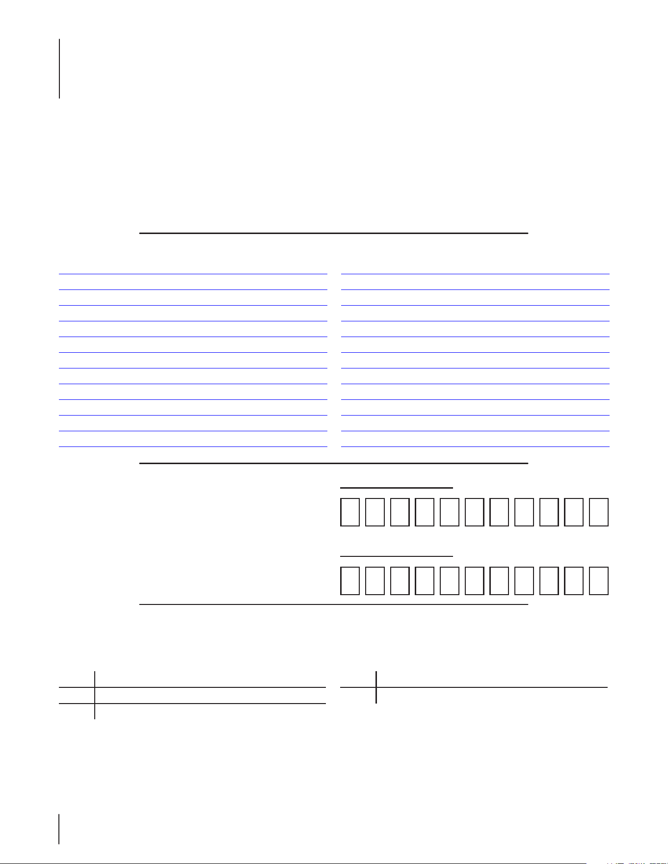
Drive Assembly
14
8
6
7
12
11
9
7
6
3
15
5
2
13
10
4
18
1
16
17
19
Ref. Part Number Description
1 634 - 05112 Rim Assembly, 12.0 x 7.0
2 918-04993 Shaft Assembly, 30.55
3 710-0465 Hex Screw, 1⁄2-20 x 4.50
4 710- 04743 Hex Screw, 1⁄4-20 x 2.50
5 710-1062 Hex Screw, 1⁄4-20 x 1.25
6 710-3008 Hex Screw, 5⁄16-18 x .75
7 712-04063 Flange Lock Nut, 5⁄16-18
8 912-3058 Hex Lock Nut, 1⁄2-20
9 714-04040 Bow-Tie Cotter Pin, 72
10 718-04428A Drive Shaft Adapter
Ref. Part Number Description
11 727-3148 Transaxle Dipstick
12 731-3245 Dipstick Holder
13 731-3297 Pump Fan, 7.0
14 736-3019 Flat Washer, .531 x 1.062 x .134
15 747-05509B Hydro Relief Lever
16 712-3050 Lug Nut, 7⁄16-14
17 934-0255 Tubeless Air Valve
18 734-04147 Tire, 23.0 x 10.5 x 12
19 703-06936 Rim Plate
4
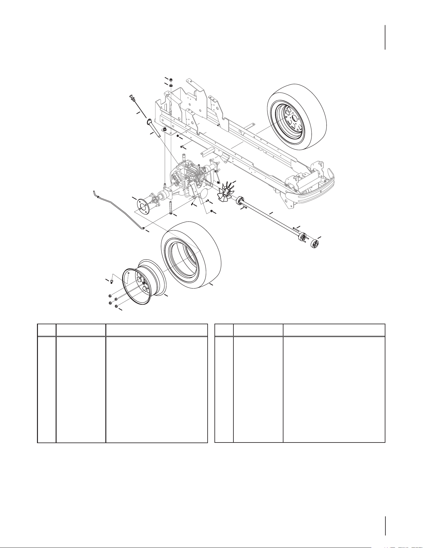
Dash Assembly
24
17
22
5
7
24
26
23
22
26
4
13
21
2
1
28
9
2
14
6
10
20
15
16
3
27
11
2
8
12
25
16
19
18
29
5
Dash Assembly
Ref. Part Number Description
1 925-04146 PTO Lever
2 710-0599 Hex Washer Screw, 1⁄4-20 x .500
3 710-0642 Hex Washer Screw, 1⁄4-20 x .750
4 925-06154 Hour/Service Minder Indicator Meter
5 725-06102A Key Switch
6 725-04363 Interlock Switch
7 625-05000 Key Assembly
8 925-1707D Battery
9 731-06598-6 Conduit
10 738-04237A Shoulder Screw, #10-32 x .500
11 747-04215 Battery Strap
12 603-04838A Steering/Battery/Dash Frame Assy.
13 703-08069 Throttle Control Mount Bracket
14 703-08226 Engine Air Upper Shield
15 710-04484 Hex Washer Screw, 5⁄16-18 x .750
16 710-05109 Hex Washer Screw, 5⁄16-14 x 1.00
17 710-1268 Hex Washer Screw, #10-16 x .375
18 931-07783 Dash
19 731-07825 LH Dash Panel
20 731-07826 RH Dash Panel
21 731-07917 Cruise/Brake Lever
22 731-3222 Choke/Throttle Control
23 731-3223 Choke/Throttle Index Disc
24 932-0334 Compression Spring, .50 x .50
25 735-0271A Bumper, .62 x .3
26 736-0204 Flat Washer, .344 x .620 x .033
27 925-05368 Wire Harness
28 725-05337 Reverse Jumper Harness
29 936-0300 Flat Washer, .406 x .875 x .059
NS 925- 05212 Headlight Harness (If Equipped)
6
Engine Accessories & Frame Assembly
A
A
3
20
47
1
2
45
37
38
17
7
27
18
24
9
17
36
39
51
13
13
51
50
46
45
43
48
8
4
47
44
35
17
32
25
10
29
28
12
16
19
10
6
47
47
47
15
20
42
49
14
5
41
10
17
11
33
7
21
10
30
40
34
22
22
23
31
Belt Shown for
Reference Only
26
7
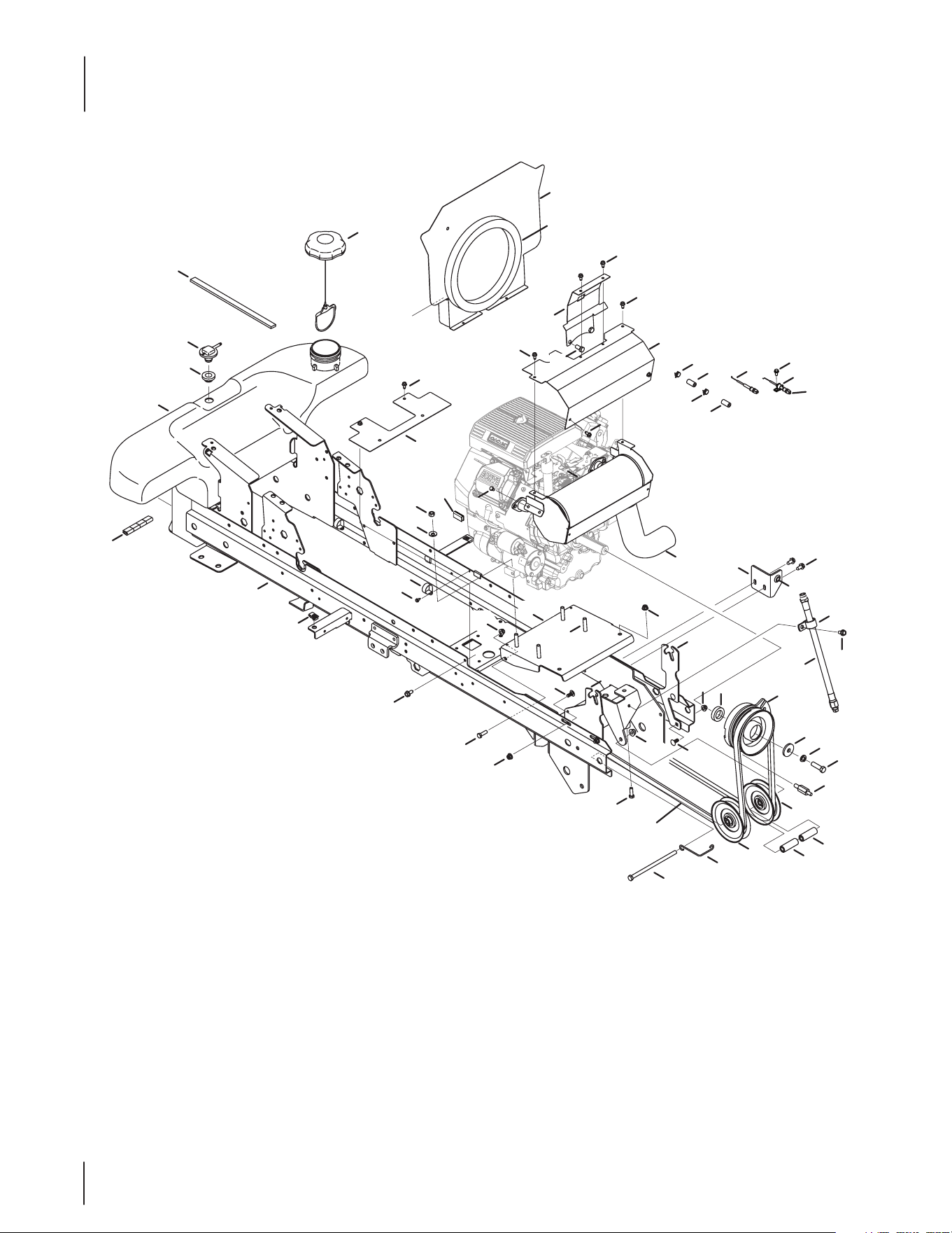
Engine Accessories & Frame Assembly
Ref. Part Number Description
1 735-04081 Rubber Grommet, 23.0 x 3.55
2 951-04274 Fuel Tank
3 751-12118 Fuel Rollover Valve
4 951-12725 Fuel Cap, 3.50
5 703-08716 Clutch Heat Shield
6 703-08713 Engine Upper Shield
7 703-08021 Engine Mount Bracket
8 703-08294 Engine Bae Plate
9 910-0224 AB Screw, #10-16 x .500
10 710-04484 Hex Washer Screw, 5⁄16-18 x .750
11 710-0539 Hex Screw, 3⁄8-24 x 1.75
12 710-0757 Hex Screw, 7⁄16-20 x 1.50
13 956-3045 Idler Pulley
14 710 -3119 Hex Screw, 3⁄8-16 x .750
15 710-3209 Hex Screw, M6-1.0 x 10
16 911-1083 Clutch Stop Stud
17 712-04063 Flange Lock Nut, 5⁄16-18
18 712-3054 Hex Lock Nut, 3⁄8-24
19 917-04895A Clutch (GT Models)
— 917-04326A Clutch (GTX Models)
20 721-04382 Tape Foam, .75 x .25
21 923-3062A Intake Gasket Foam
22 726-0205 Hose Clamp
23 726-0272 Clamp, 9⁄16
24 726 - 0 4119 Hose Clamp, 1.0
25 726-0475 Clamp, 1.0
26 731-08383-2 Trim Strip
27 736-0105 Spring Washer, .401 x .870 x .060
Ref. Part Number Description
28 936 - 0171 Lock Washer, 7⁄16
29 736-3082A Flat Washer, .45 x 1.5 x .172
30 946-04759A Choke Control Cable
31 946-04771A Throttle Control Cable
32 750-04603 PTO Spcr., 1.00 x 1.62 x .4 (GT Models)
— 750-3356 PTO Spcr., 1.13 x 1.62 x .21 (GTX Models)
33 751-10291A Oil Drain Hose
34 751-10349-13 Low Permeation Fuel Hose
35 703-08768A Hood Tilt Bracket
36 651-04379A Pipe Assembly Heat Shield
37 703-08780 Exhaust Bracket
38 735-04291 Grommet, .875 OD x .375 ID x .188
39 751-12647 Twin Muer
40 751-12089 -34 Vent Hose
41 710-0643 Hex Screw, 5⁄16-18 x 1.00
42 603-04936 Frame (GT Models)
— 603-04939 Frame (GTX Models)
43 703-08077 Lower Bae
44 703-08766A Hood Pivot Bracket
45 710-0451 Carriage Bolt, 5/16-18 x .750
46 710-04692 Hex Screw, 3/8-16 x 7.25
47 710-0599 Hex Washer Screw, 1/4-20 x .500
48 712- 04065 Flange Lock Nut, 3/8-16
49 926 - 0211 U-Nut, 5/16-18
50 932-0970 Belt Guide
51 750-04198A Idler Spacer, .41 x .875 x 2.19
NS 722-3020 Foam, 1.25 x .62
NS 725- 0157 Cable Tie, 3/16 x .05 x 7.4
8
17
15
9
13
6
12
8
14
16
4
10
8
2
1
23
18
9
3
4
9
5
26
25
23
7
24
20
19
27
27
11
22
21
22
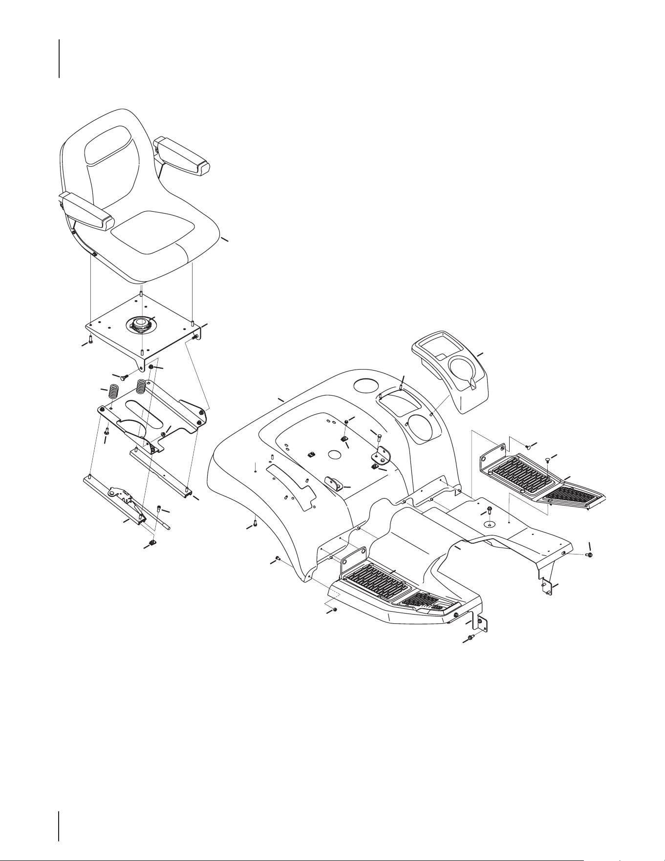
Seat & Fender Assembly
9
Ref. Part Number Description
1 731- 07912 LH Cup/Compartment Cover
2 703-08025A Seat Mount Plate
3 703-08164 Suspension Seat Front Pivot Bracket
4 710-0376 Hex Screw, 5⁄16-18 x 1.00
5 710-04043 Hex Flange Screw, 5⁄16-18
6 710-1314A Socket Screw, 5⁄16-18 x .750
7 735-04256 RH Floor Pad
8 712-04063 Flange Lock Nut, 5⁄16-18
9 926 - 0211 U-Nut, 5⁄16-18
10 938-0296 Shoulder Screw, 5⁄16-18 x .437 x .268
11 735-04258 LH Floor Pad
12 703- 08178 Seat Track w/o Latch
13 703- 08179A Seat Track w/ Latch
14 710-0276 Carriage Screw, 5⁄16-18 x 1.00
15 725-05208 Seat Switch, 1⁄4
16 732-0735A Compression Spring
17 757-04140 Seat
18 703-07868 Fender
19 703-07910 Running Board
20 703-08042A RH Running Board Bracket
21 703-08499 LH Running Board Bracket
22 710-0602 Hex Washer Screw, 5⁄16-18 x 1.000
23 710-0895 Hex Washer Screw, 1⁄4-15 x .750
24 710 -1260A Hex Washer Screw, 5⁄16-18 x .750
25 710 -3013 Hex Screw, 1⁄4-20 x .50
26 712-0324 Hex Lock Nut, 1⁄4-20
27 726-3046 Ratchet Clip, .250
NS 731-08383-2 Trim Strip, 5⁄32
Seat & Fender Assembly
10
15
8
16
5
11
9
16
8
11
9
5
1
12
1
7
4
13
3
10
2
6
17
2
4
10
14
12
3
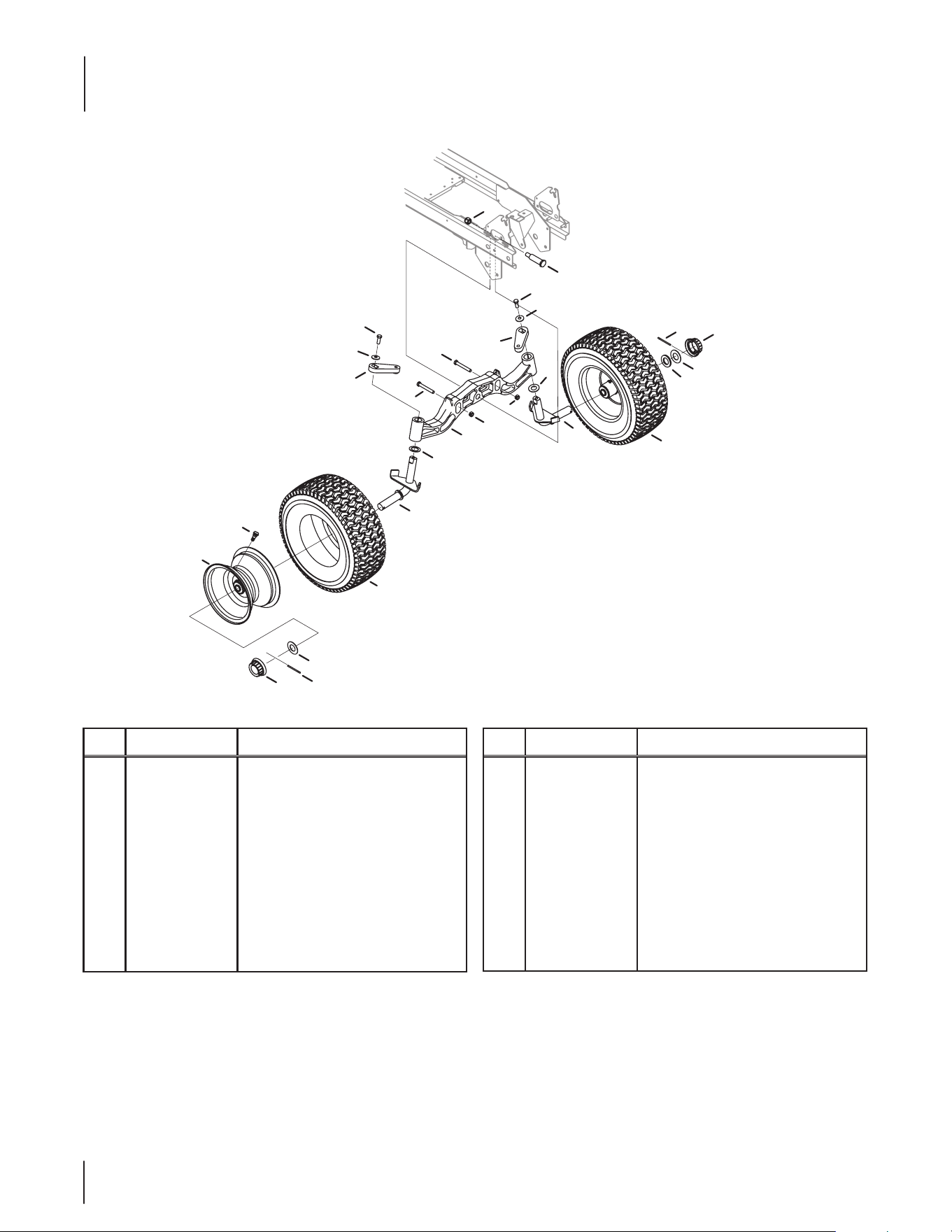
Ref. Part Number Description
1 903- 04913 Axle Assembly, 3⁄4
2 710-3066 Hex Screw, 3⁄8-16 x 2.75
3 710-0591 Hex Cap Screw, 3/8-24 x 1.00
4 712-0375 Hex Lock Nut, 3⁄8-16
5 714 - 0211 Cotter Pin, 3/16 x 2.0
6 712-3083 Hex Lock Nut, 1⁄2-13
7 719- 04721B Pivot Bar
8 934-0255 Tubeless Air Valve
9 731-09347 Hubcap
Ref. Part Number Description
10 736-0331 Bevel Washer, .390 x 1.130 x .062
11 736-05026 Flat Washer, 1.05 x 1.92 x .06
12 736-0745 Thrust Washer, 1.010 x 2.50 x .060
13 938 -3110 Shoulder Screw, .750 x 2.23
14 748- 04286 Steering Arm, LH
15 934-04722 Rim Assembly, 16.0 x 6.5 x 8
16 734 -1727 Tire, 16.0 x 6.50-8.00
17 748-04290 Steering Arm, RH
Front Axle Assembly
11
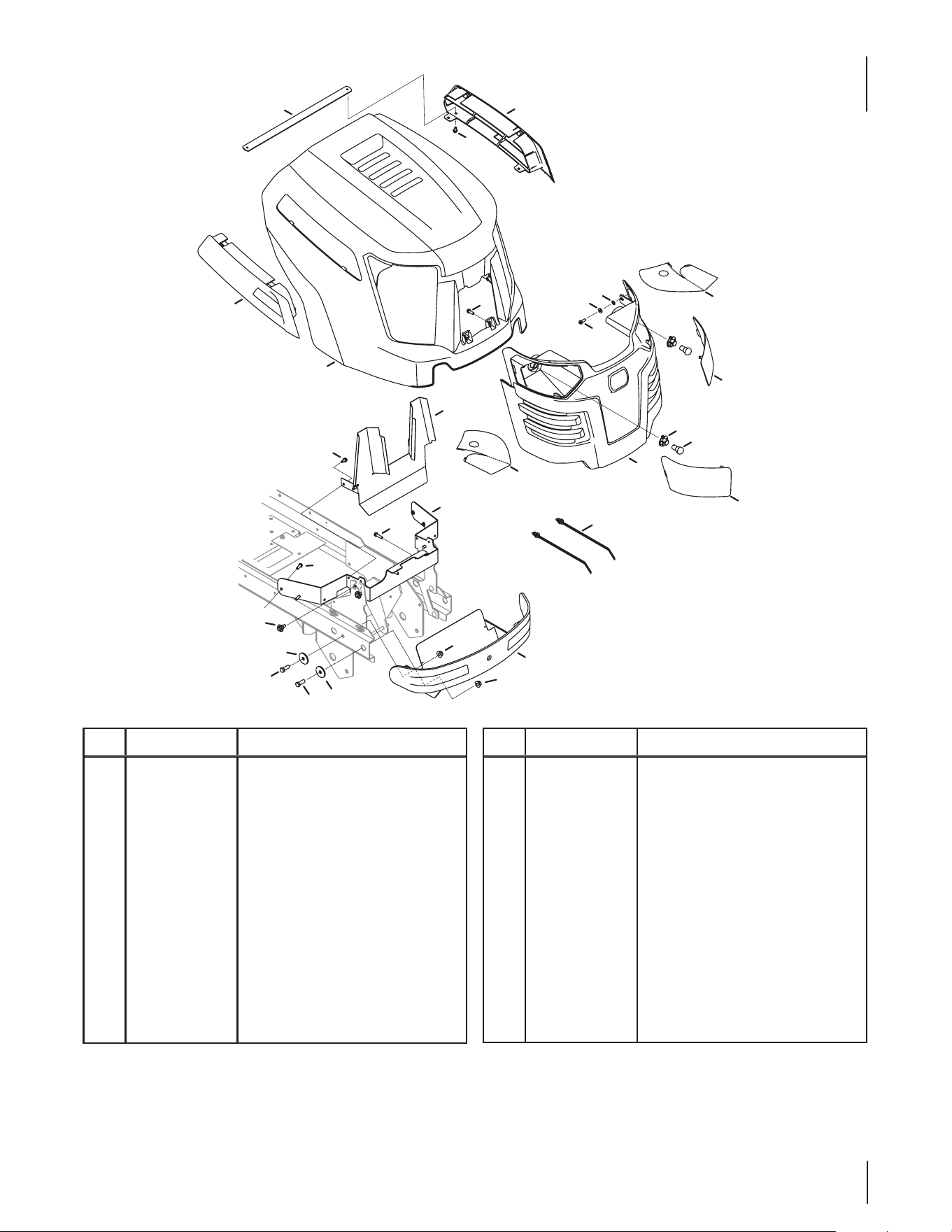
Hood Assembly
Ref. Part Number Description
1 603-04945A Front Bumper Assembly
2 925-0963 Bulb
3 931-04563A Grill
4 703-08756 Heat Shield
5 703-08760 Hood Pivot Bracket
6 710-05108 Hex Washer Screw, 1⁄4 x .750
7 710-05109 Hex Washer Screw, 5⁄16-14 x 1.00
8 710-0514 Hex Screw, 3⁄8-16 x 1.00
9 710-0599 Hex Washer Screw, 1⁄4-20 x 0.500
10 712-04065 Flange Lock Nut, 3⁄8-16
11 926-0154 Cable Tie, 7.5
12 931-06542B RH Hood Scoop
Ref. Part Number Description
13 931-06543B LH Hood Scoop
14 931-08482 Hood
15 936-0222 Lock Washer, 1⁄4
16 936-0227 Flat Washer, .390 x 1.500 x .134
17 936-3020 Flat Washer, .271 x .630 x .065
18 738- 04091A Shoulder Screw, 5⁄16-18 x .43 x .29
19 925-1649 1⁄4-turn Socket
20 931-07878 RH Hood Lens
21 931-07879 LH Hood Lens
22 777X44662 Left Lens Reector Label
23 777X44663 Right Lens Reector Label
24 703-08787A Cross Brace
11
12
7
13
14
15
17
9
3
2
19
21
22
20
23
4
9
10
10
1
16
8
18
6
7
5
8
16
9
24
12
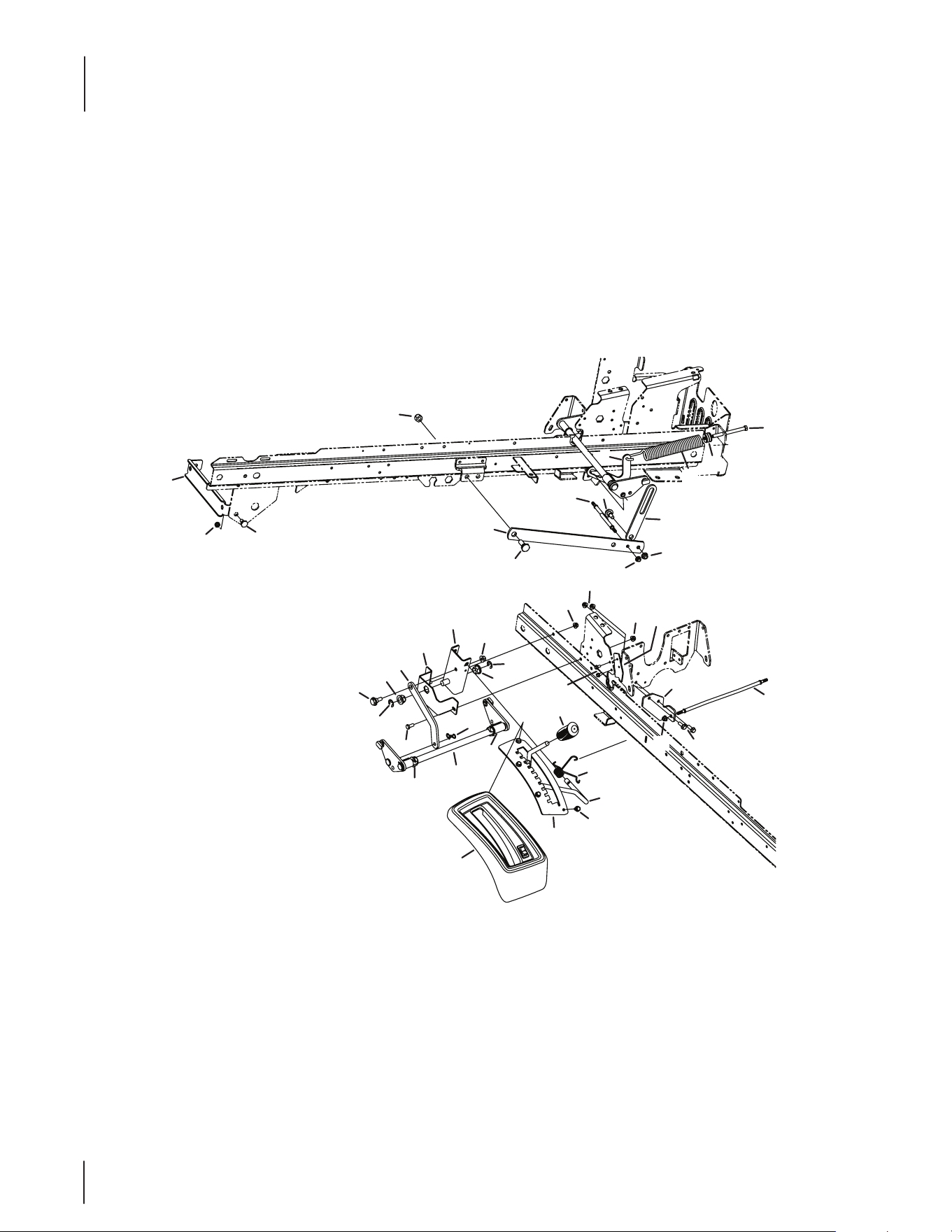
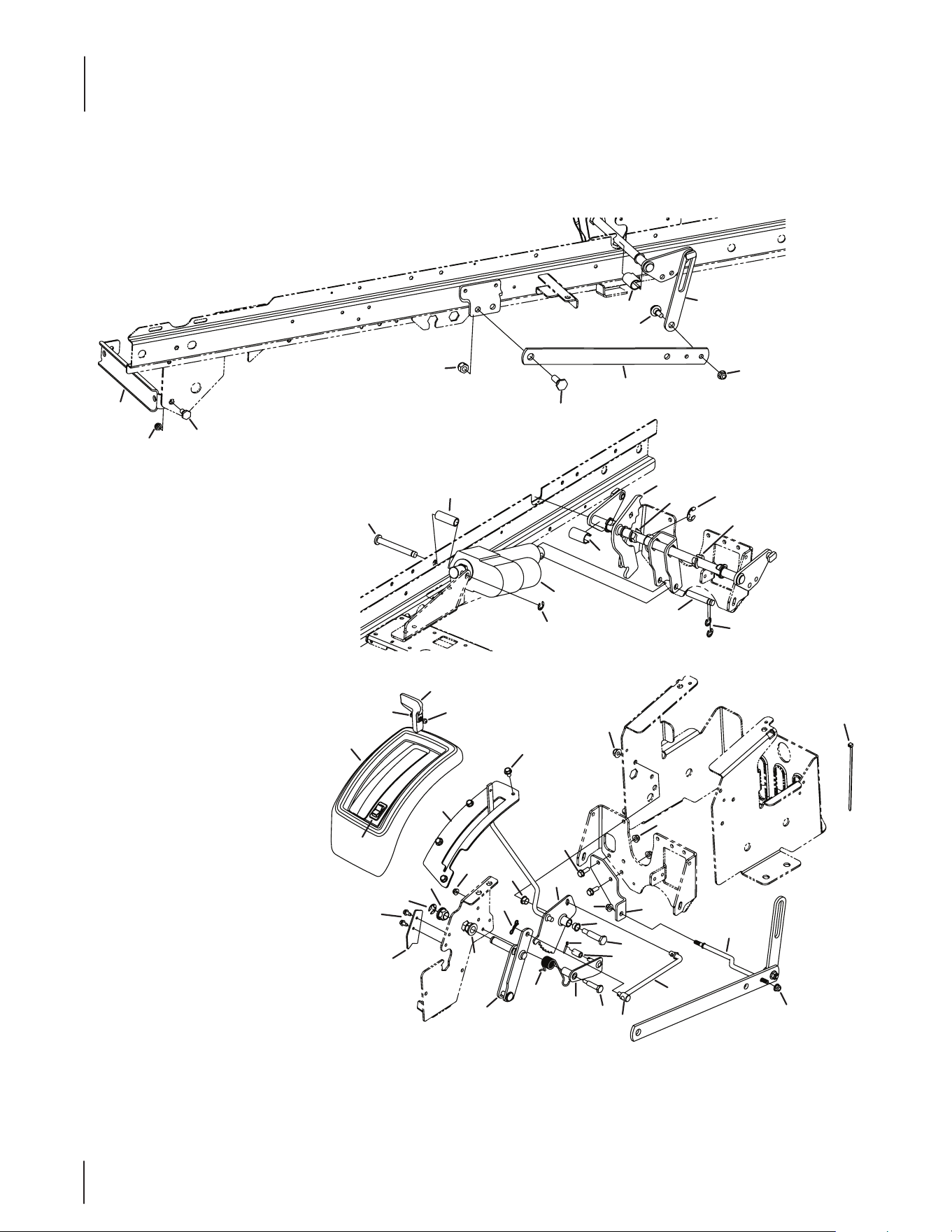
Manual Deck Lift
17
16
27
9
19
18
28
30
4
8
34
35
3
29
20
32
1
24
21
15
22
28
31
6
7
31
22
19
2
23
26
33
13
5
25
10
14
18
34
18
18
12
18
11
13
Ref. Part Number Description
1 603-04854A Manual Lift Shaft Assembly
2 603-04857 Manual Lift Lever Bracket Assembly
3 703-07954A Front Hanger Bracket
4 703-07993A Lift Link
5 703-08170 Manual Lift Index Bracket
6 703-08224 Manual Lift Link Plate
7 703-08225A Manual Lift Lever Mount Bracket
8 703-08245B Link Lift Plate
9 703-08319 Extension Spring Plate
10 703- 08474 Sway Bar Mount Bracket
11 703-08485 Bearing Stop Plate
12 710-0599 Hex Washer Screw, 1⁄4-20 x .500
13 710-0604A Hex Washer Screw, 5⁄16-18 x .625
14 710-1238 Hex Washer Screw, 5⁄16-18 x .875
15 710-3008 Hex Screw, 5⁄16-18 x .75
16 710-3279 Hex Screw, 3⁄8-16 x 4.25
17 711- 0635 Spring Insert
18 712-04063 Flange Lock Nut, 5⁄16-18
19 712- 04065 Flange Lock Nut, 3⁄8-16
20 712-3083 Hex Lock Nut, 1⁄2-13
21 714-04043 Bow-Tie Cotter Pin
22 716-0106A E-Ring, .625
23 720- 04139B Cub Grip
24 731-07993A Spacer
25 731- 08177 Lif Manual Cover
26 732-04869A LH Torsion Spring
27 732-3093 Extension Spring, 1.485 x 9.68
28 738-04428 Shoulder Screw, 3⁄8-16 x .562 x .360
29 738-0234 Shoulder Screw, 1⁄2 x .29
30 938-0744A Shoulder Screw, 1⁄2-13 x .625 x .36
31 941-0225 Hex Flange Bearing
32 741-04504 Hex Flange Bearing
33 747-05426 Manual Lift Handle Rod
34 747-05462 Anti-Sway Deck Rod
35 712-0266A Jam Lock Nut, 3⁄8-16
NS 731-04010 Switch Plug Panel
Manual Deck Lift
14
5
35
46
7
21
6
38
22
34
31
25
15
31
40
27
40
2
25
29
16
18
32
11
30
10
12
26
39
20
8
13
21
17
37
1
33
44
24
36
41
9
3
39
23
41
4
14
19
42
19
43
28
19
45
47
Electric Deck Lift
15
Ref. Part Number Description
1 603-04827 Hub Lift Assembly
2 603-04836 Electric Shift Assembly
3 603-04837A Deck Height Adjustment Weldment
4 603-04861 Lift Lever Bracket Assembly
5 703-07954A Front Hanger Bracket
6 703-07993A Lift Link
7 703-08245B Lift Link Plate
8 703-08254A Index Bracket
9 703- 08474 Sway Bar Mount Bracket
10 703-08485 Bearing Stop Plate
11 710-0425 Machine Screw, #10-24 x .625
12 710-0599 Hex Washer Screw, 1⁄4-20 x .500
13 710-0604A Hex Washer Screw, 5⁄16-18 x .625
14 710-1238 Hex Washer Screw, 5⁄16-18 x .875
15 711- 05 489 PIN, .50 x 3.5
16 711-05501A Clevis Pin, .50 x 4.0
17 911- 0 832 Ferrule, 3⁄8-24 x .375
18 712-0161 Hex Lock Nut, #10-24
19 712- 04063 Flange Lock Nut, 5⁄16-18
20 712-04064 Flange Lock Nut, 1⁄4-20
21 712-04065 Flange Lock Nut, 3⁄8-16
22 712-3083 Hex Lock Nut, 1⁄2-13
23 714-04040 Bow-Tie Cotter Pin, 72
24 914-0474 Cotter Pin, .125 x .75
25 916-0104 E-Ring, .500
Ref. Part Number Description
26 716-0106A E-Ring, .625
27 716- 0136 E-Ring, .875
28 725-0157 Cable Tie, 3⁄16 x .05 x 7.4
29 725-04500 Plow Lift Actuator
30 731-07913 Lift Cover
31 731-07993A Spacer
32 731-08170 Electric Lift Knob
33 732-0874 Torsion Spring
34 738-0234 Shoulder Screw, 1⁄2 x .29
35 738-04428 Shoulder Screw, 3⁄8-16 x .562 x .360
36 938-0533 Shoulder Screw, .498 x 1.635
37 938-0560 Shoulder Screw, .374 x 1.375
38 938-0744A Shoulder Screw, 1⁄2-13 x .625 x .36
39 941-0225 Hex Flange Bearing
40 741-04504 Hex Flange Bearing, .78
41 741-0491 Flange Bearing, .500 x .34
42 747-05456 Electric Lift Rod Adjuster
43 747- 05462 Anti-Sway Deck Rod
44 750-05505A Spacer, .35 x .5 x .851
45 725-04704 Plow Lift Switch
46 712-0266A Jam Lock Nut, 3⁄8-16
47 750-05594 Spacer, .55 ID x .75 OD x 2.06
NS 925- 05190A Electric Deck Lift Harness
NS 725-1543 30 Amp Fuse
Electric Deck Lift
16
19
31
36
40
28
17
6
35
37
16
16
38
39
21
38
13
30
18
5
32
15
23
9
1
11
26
16
21
33
12
11
25
21
38
8
22
24
19
7
19
23
16
2
29
34
19
21
38
3
18
14
27
4
10
32
39
39
20
15
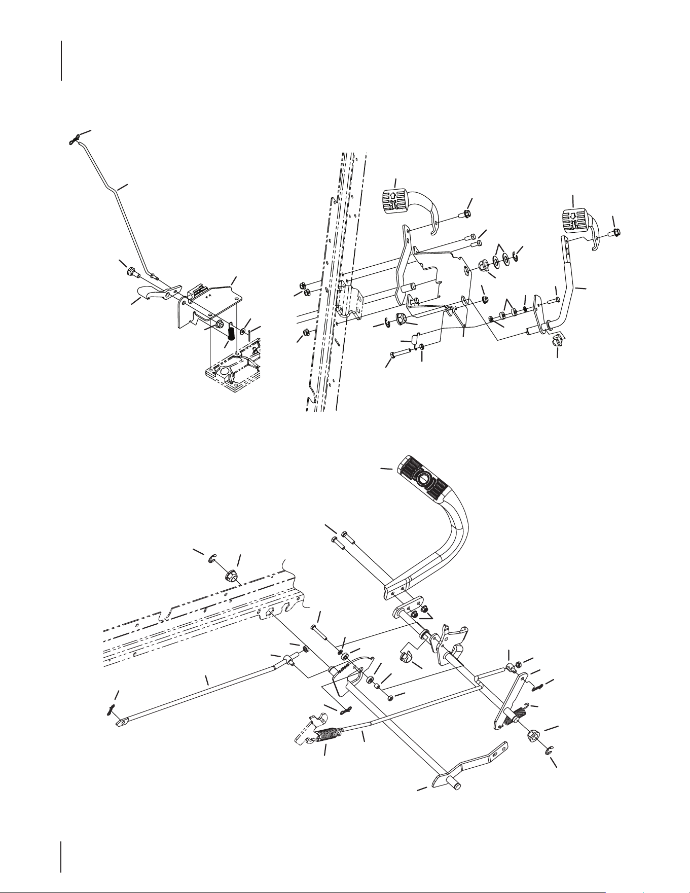
Pedal Controls
17
Ref. Part Number Description
1 603-04807 Reverse Shaft Assembly
2 603-04933 Forward Shaft Assembly
3 603-04934 Brake Shaft Assembly
4 711- 0392 Ferrule, 3⁄8-16 x .312
5 703-07921 Pedal Bracket
6 703-08010B Cruise Pedal Mount Bracket
7 710-0136 Hex Screw, 1/4-20 x 1.75
8 710-0528 Hex Screw, 5⁄16-18 x 1.25
9 710-0597 Hex Screw, 1⁄4-20 x 1.00
10 912-3008 Jam Nut, 3/8-16
11 710-0623 Hex Washer Screw, 3⁄8-16 x .750
12 710-3008 Hex Screw, 5⁄16-18 x .75
13 710-3180 Hex Screw, 5⁄16-18 x 1.75
14 711-1155 Ferrule, 5⁄16-18 x .312
15 912-0291 Hex Lock Nut, 1⁄4-20
16 712-04063 Flange Lock Nut, 5⁄16-18
17 712-04065 Flange Lock Nut, 3⁄8-16
18 712-3007 Jam Nut, 5⁄16-18
19 714-04040 Bow-Tie Cotter Pin, 72
20 750-05654 Spacer, .375 x .25 x .335
Ref. Part Number Description
21 716-0106A E-Ring, .625
22 719 -04647A Pedal Bracket
23 741-3065B Hex Flange Bearing, .628
24 747-05702 Hydro Control Rod
25 731-3247 Forward Pedal
26 731-3248 Reverse Pedal
27 732-04323B Extension Spring, .770 x 3.720
28 732-04354 Cruise Extension Spring
29 732-04889 Extension Spring, .95 x 4.00
30 932-3002 Extension Spring, .51 x 2.12
31 747- 05408 Latch Control Rod
32 936-0142 Flat Washer, .281 x .50 x .063
33 736-0187 Flat Washer, .64 x 1.24 x .06
34 747-05439A Brake Rod
35 748- 04203 Cruise Latch
36 936-3020 Flat Washer, .271 x .630 x .065
37 938-0380 Shoulder Screw, 3⁄8-16 x .50 x .27
38 941-0225 Hex Flange Bearing
39 741-04280 Ball Bearing, .25 x .6875 x .25
40 914 - 0111 Cotter Pin 3/32” Dia. x 1” Lg.
Pedal Controls
18
28
12
35
42
29
34
38
3
42
17
2
39
1
27
21
37
5
30
16
16
4
37
7
18
41
10
11
9
22
25
10
11
23
20
33
40
32
12
35
31
20
15
26
8
18
6
13
36
24
19
14
43
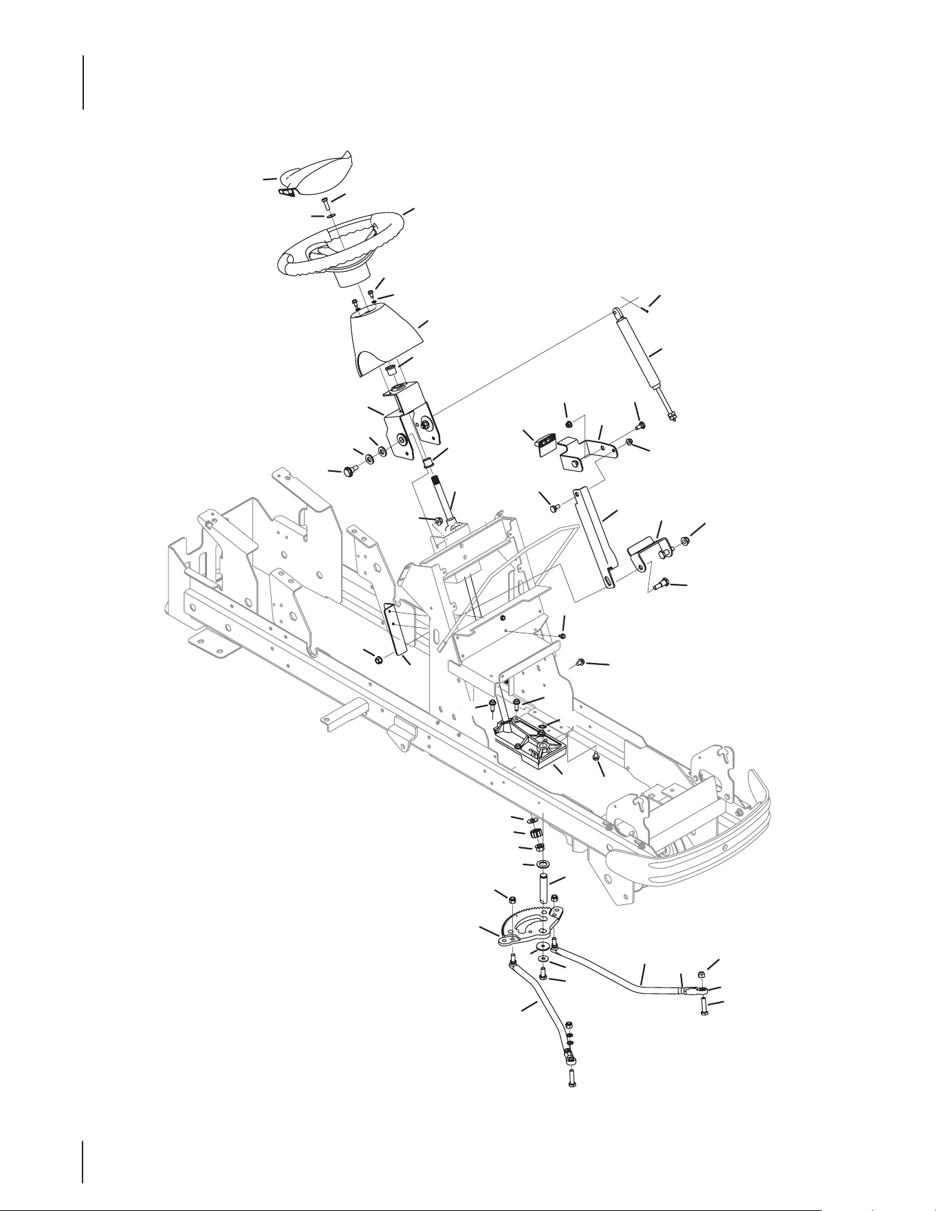
Manual Steering Assembly
19
Ref. Part Number Description
1 603-04852B Steering Upper Support Bracket
2 617- 04095A Manual Steering Assembly
3 631-04008A Steering Wheel
4 703-08105A Tilt Steering Lever Bracket
5 703 - 08114A Tilt Steering Bracket
6 703-08180 Tilt Steering Mount Bracket
7 703-08505 Tilt Steering Pivot Bracket
8 710-0151 Hex Screw, 3⁄8-24 x 2.00
9 710-0599 Hex Washer Screw, 1⁄4-20 x .500
10 710-0602 Hex Washer Screw, 5⁄16-18 x 1.000
11 710-0604A Hex Washer Screw, 5⁄16-18 x .625
12 710-0643 Hex Lock Screw, 5⁄16-18 x 1.00
13 936-0255 Flat Washer, .510 x 1.14 x .040
14 736-0505 Flat Washer, .340 x 1.50 x .150
15 912- 0240 Jam Nut, 7⁄16-20
16 712-04063 Flange Lock Nut, 5⁄16-18
17 712-04065 Flange Lock Nut, 3⁄8-16
18 912-0431 Flange Lock Nut, 3⁄8-16
19 712-0459 Flange Lock Nut, 7⁄16-20
20 912-3061 Hex Lock Nut, 3⁄8-24
21 914- 0507 Cotter Pin, 3⁄32 x .750
22 916-0101 Snap Ring, .750
Ref. Part Number Description
23 717-04870A Segment Gear
24 717-04943 Pinion Gear
25 919-04756B Steering Housing
26 723-04089 End Rod, 7⁄16-20 x 3⁄8
27 927-04320 Locking Damper Cylinder
28 731-04532B Steering Wheel Cover
29 731-07815A Dash Collar
30 731-3224 Tilt Lever
31 747- 05424A LH Drag Link, 5⁄8
32 747-05425A RH Drag Link, 5⁄8
33 736-04571 Flat Washer, .76 x 1.25 x .10
34 736-0204 Flat Washer, .344 x .62 x .033
35 736-0242 Bell Washer, .340 x .872 x .060
36 736-3084 Thrust Washer, .510 x 1.12 x .060
37 938-0140 Shoulder Screw, .435 x .178-5⁄16 x .56
38 738-04278 Shoulder Screw, 1⁄4-20 x 0.500
39 738-04484 Shoulder Bolt, 3⁄8-16 x .49 x .33
40 738-04538 Steering Shaft
41 738-04495 Shoulder Screw, 3⁄8-16 x .50 x .66
42 941- 0353 Flange Bearing, .630
43 736-0626 Flat Washer, .580 x 1.125 x .080
Manual Steering Assembly
20
3
52
42
36
21
37
19
33
44
40
4
41
14
34
22
2
45
48
1
48
7
47
9
43
6
35
21
43
21
32
26
38
51
23
8
3
19
21
12
27
12
30
15
15
11
24
29
50
49
14
41
28
25
46
25
39
31
10
25
20
16
17
18
15
15
5
A
15
13
15
A
53
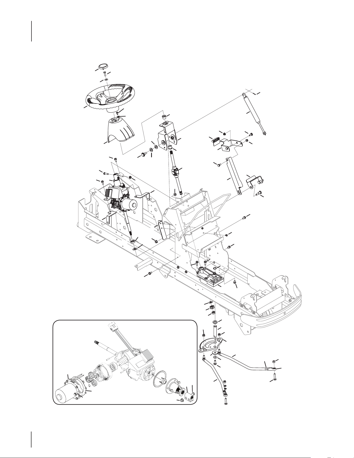
Power Steering Assembly
21
Ref. Part Number Description
1 603-04852B Upper Steering Support Bracket
2 617- 04096A Power Steering Assembly
3 918-05083A Transmission Assembly
4 631-04556 Steering Wheel
5 703-08628 Power Steering Mount Box, RH
6 703-08105A Tilt Steering Lever Bracket
7 703 - 08114A Tilt Steering Bracket
8 703-08180 Tilt Steering Mount Bracket
9 703-08505 Tilt Steering Pivot Bracket
10 710-0151 Hex Screw, 3⁄8-24 x 2.00
11 710-0599 Hex Washer Screw, 1⁄4-20 x .500
12 710-0602 Hex Washer Screw, 5⁄16-18 x 1.000
13 703-08629 Power Steering Mount Box, LH
14 710-0643 Hex Lock Screw, 5⁄16-18 x 1.00
15 710-04484 Hex Washer Screw, 5⁄16-18 x .750
16 936-0255 Flat Washer, .510 x 1.14 x .040
17 736-0505 Flat Washer, .340 x 1.50 x .150
18 736-3084 Thrust Washer, .510 x 1.12 x .060
19 710-3083 Hex Screw, 5⁄16-18 x 1.375
20 912-0240 Jam Nut, 7⁄16-20
21 712-04063 Flange Lock Nut, 5⁄16-18
22 712- 04065 Flange Lock Nut, 3⁄8-16
23 912-0431 Flange Lock Nut, 3⁄8-16
24 712-0459 Flange Lock Nut, 7⁄16-20
25 912-3061 Hex Lock Nut, 3⁄8-24
26 914- 0507 Cotter Pin, 3⁄32 x .750
27 916-0101 Snap Ring, .750
Ref. Part Number Description
28 717- 04870A Segment Gear
29 717-04943 Pinion Gear
30 919-04756B Steering Housing
31 723-04089 End Rod, 7⁄16-20 x 3⁄8
32 927-04320 Locking Damper Cylinder
33 731-04039 Cap
34 731-07815A Dash Collar
35 731-3224 Tilt Lever
36 924-04097 Electric Motor
37 748-04240 Steering Shaft Coupler
38 736-0187 Flat Washer, .64 x 1.24 x .06
39 736-04571 Flat Washer, .76 x 1.25 x .10
40 736-0204 Flat Washer, .344 x .62 x .033
41 736-0242 Bell Washer, .340 x .872 x .060
42 710-0809 Hex Washer Screw, 1⁄4-20 x 1.250
43 938-0140 Shoulder Screw, .435 x .178-5⁄16 x .56
44 738-04278 Shoulder Screw, 1⁄4-20 x 0.500
45 738-04484 Shoulder Bolt, 3⁄8-16 x .49 x .33
46 738-04538 Steering Shaft
47 738-04495 Shoulder Screw, 3⁄8-16 x .50 x .66
48 941-0353 Flange Bearing, .630
49 747-05424A LH Drag Link, 5⁄8
50 747-05425A RH Drag Link, 5⁄8
51 748-04269 Ring Spacer Hub
52 721-04431 Motor Gasket
53 736-0626 Flat Washer, .580 x 1.125 x .080
Power Steering Assembly
22
39
45
31
52
34
35
57
54
57
26
46
55
55
5646
55
55
6
51
58
58
14
9
60
58
59
29
4
43
28
19
30
17
27
44
58
48
42
25
38
8
6
59
58
60
53
24
21
59
58
62
61
63
65
10
64
5
36
15
12
18
2
32
49
50
22
41
47
7
33
23
37
67
3
13
1
16
11
66
68
40
69
67
69
40
20
Transaxle Assembly
23
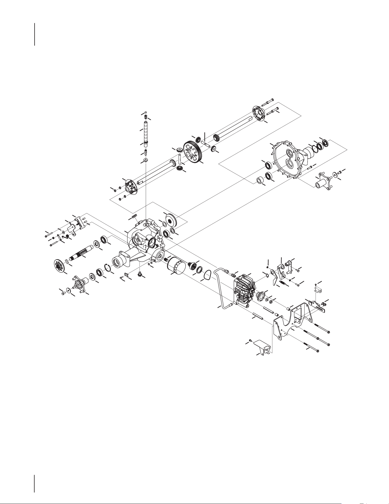
Transaxle Assembly
Ref. Part Number Description
1 603-04340A Neutral Return Arm Assembly
2 603-0707B Torq Bracket Assembly
3 603-04921 Neutral Return Arm Assembly
4 617-3002 Pinion Gear, 13T
5 761-3074 Brake Arm Actuator
6 918-04317 Wheel Hub Assembly
7 918-3243 Pump Assembly
8 919 -3071A RH Housing
9 619-3072 LH Housing
10 710 -1206 Hex Washer Screw, 1⁄4-20 x 2.375
11 703-05042 Neutral Arm, LH
12 703-4093 Hydro Dump Spring Plate
13 710-04171 Hex Screw, 5⁄16-24 x .625
14 710-0573 Hex Lock Screw, 5⁄16-18 x 1.25
15 710-0599 Hex Washer Screw, 1⁄4-20 x .500
16 710-0607 Hex Washer Screw, 5⁄16-18 x .500
17 710-1633 Plug Screw, M14 x 1.5 x .827
18 710-1888 Hex Washer Screw, 5⁄16-18 x 5.350
19 710-3015 Hex Screw, 1⁄4-20 x .75
20 710-0597 Hex Screw, 1/4-20 x 1.00
21 711-13 85A Output Shaft, 9T
22 712-3059 Jam Lock Nut, 1⁄2-20
23 716 - 0111 Retaining Ring, .875
24 917-0678 Brake Pad
25 717-3449 Bevel Gear, 54T
26 710-3144 Hex Screw, 3⁄8-16 x 2.00
27 721-0459 0-Ring, .426 x .566 x .070
28 721-0519 Gland Seal
29 923-3014 Oil Filter
30 726-0295 Tube Clamp, .500
31 926-0324 Fuel Clamp
32 727-0636 Hydro Pick-Up Tube
33 927-3002 Straight Fitting
34 731-1480 Plastic Vent
35 731-1481 Plastic Vent Cap
Ref. Part Number Description
36 761-0207A Brake Yoke
37 732-3119A Extension Spring, .50 x 1.98
38 735-0277A Rubber Grommet, .750 x 1.063 x .4375
39 735-0279 Grommet, .362 x .56 x .63
40 912- 0298 Jam Nut, 1/4-20
41 936-0253 Bell Washer, .525 x 1.00 x .050
42 736 -0615 Thrust Washer, 1.007 x 1.542 x .03
43 736 -0619 Spring Washer, 1.595 x 2.011 x .030
44 937-3022 Filter Nipple Fitting
45 737-3092 Tube Fitting, .500
46 711-1052A Shaft, .500 x 3.005
47 748-3093 Hydro Pump Adaopter
48 750-3346 Axle Spacer, 1.007 x 1.665 x .141
49 750-3349 Hydro Spacer, .323 x .443 x 3.51
50 750-3350 Hydro Spacer, .323 x .600 x .740
51 750-3358 Axle Spacer, 1.007 x 1.665 x .989
52 751-0588-18 Fuel Line, 1⁄2
53 761-0215 Disc Brake
54 712-0266A Jam Lock Nut, 3⁄8-16
55 917-1446B Miter Gear
56 917-1568 Spur Gear
57 919-0375A RH Housing Dierential
58 741-3114 Ball Bearing, 1 x 52 x 15
59 721-0523 Oil Seal, 1.00 x 2.047 x .2755
60 716-0204 Retainer Ring
61 912- 0273 Hex Lock Nut, 5⁄16-24
62 761-0208 Anti-Rotation Brake Bracket
63 732-0925 Torsion Spring, .75 x 3
64 736-0371 Flat Washer, .343 x .880 x .062
65 941- 0343 Brake Actuator Pin
66 703-08779 Neutral Arm
67 710 -3119 Hex Cap Screw, 3/8-16 x .750
68 738- 04237A Shoulder Screw, 10-32 x .500
69 936-0227 Flat Washer, .390 x 1.50 x .134
24
4
62
43
46
65
46
43
62
59
55
15
54
26
48
37
13
56
57
14
44
60
12
1
52
4
52
38
28
25
8
45
8
19
30
27
34
11
58
19
31
2
37
48
26
32
40
7
9
51
6
47
33
18
19
16
64
63
61
5
23
49
53
17
19
22
41
19
29
20
50
24
8
42
42
39
42
35
35
8
42
42
19
3
10
36
21
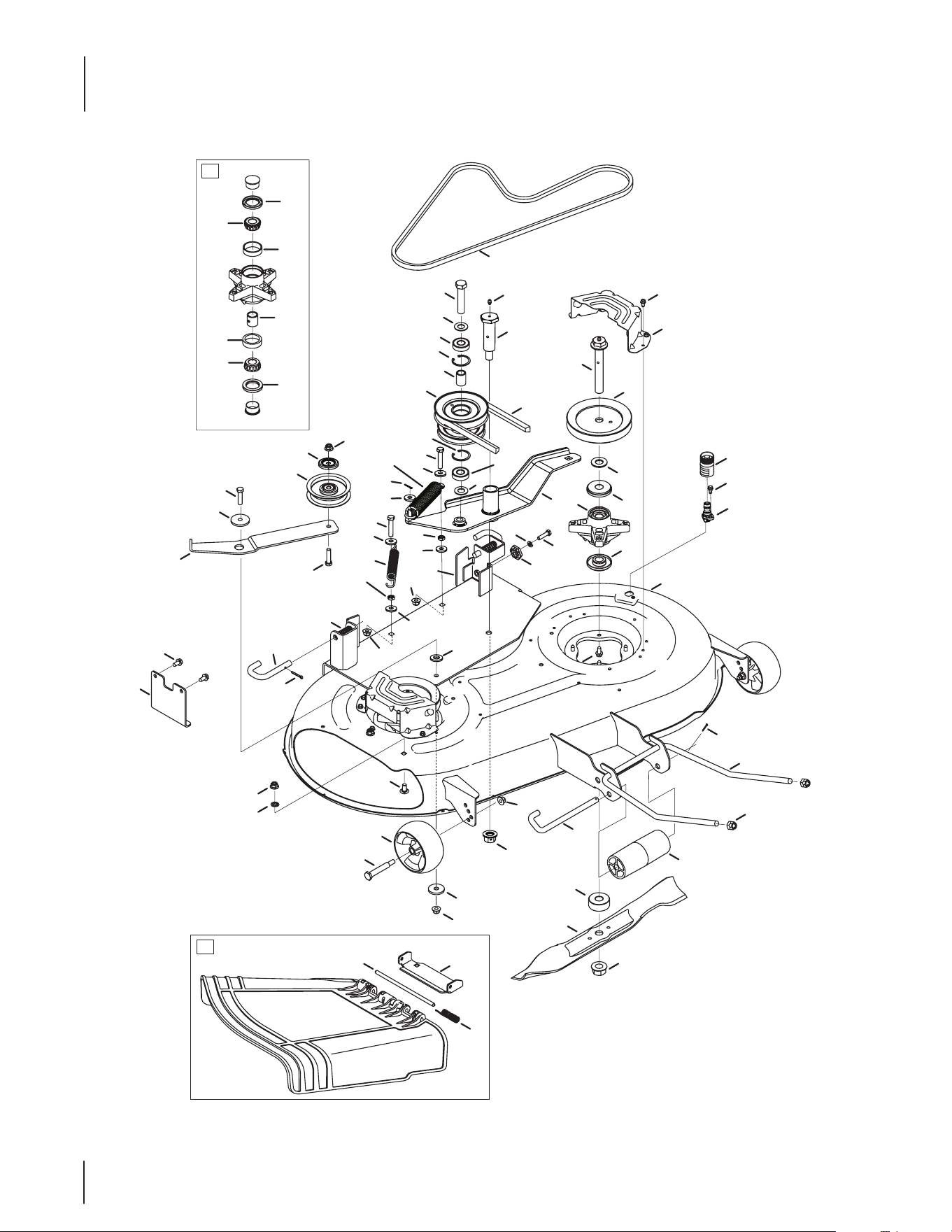
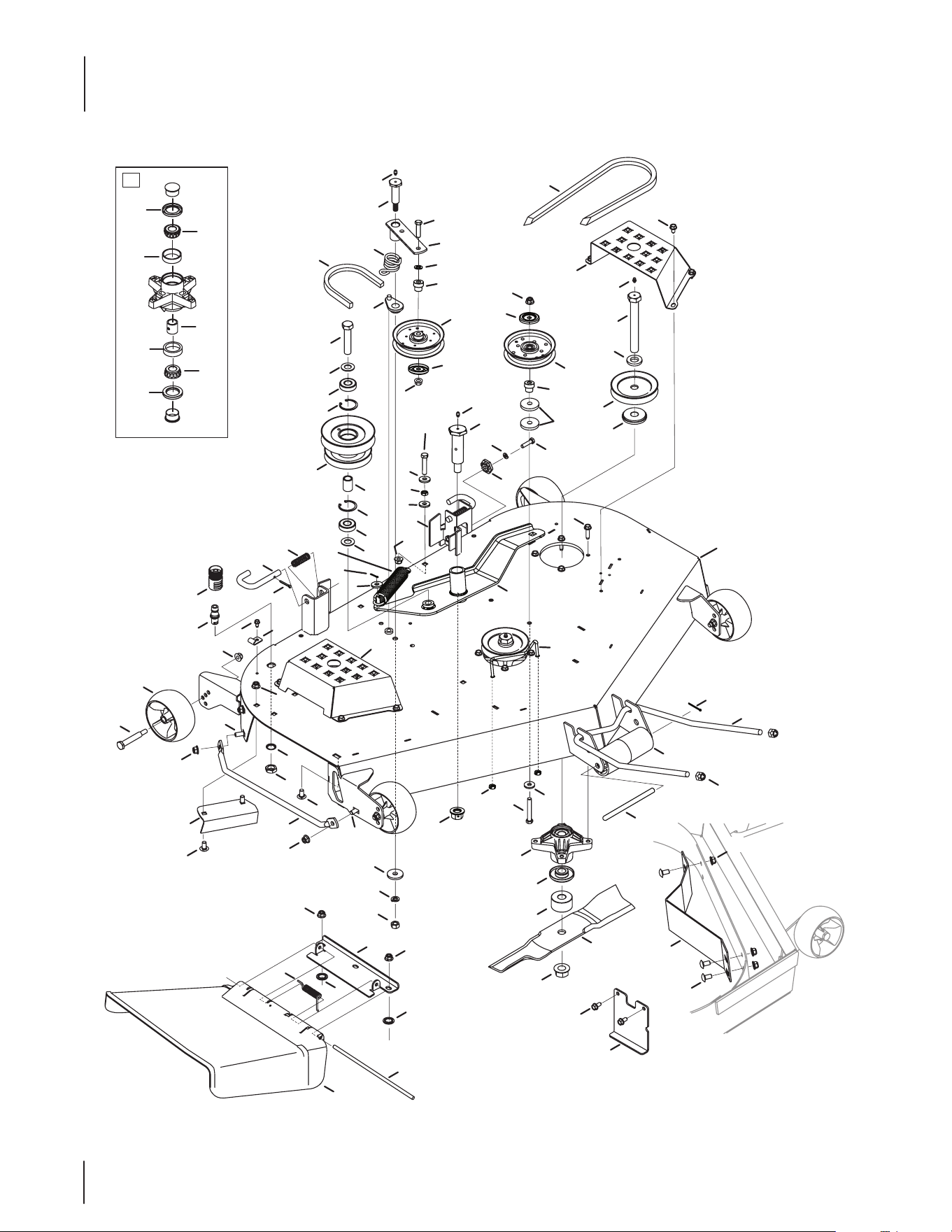
42” Stamped Deck

25
Ref. Part Number Description
1 903-04819C Deck Assembly
2 603-04851B PTO Idler Assembly
3 603-04859 Hanger Adjustment Bracket
4 918-3129C Spindle Assembly
5 631-05191 Chute Ass’y, Deector 42” Oset
6 703-08286 Idler Bracket
7 703-08425 Up-Stop Front Bracket
8 710-0347 Hex Screw, 3⁄8 x 16 x 1.75
9 710-04484 Hex Washer Screw, 5⁄16-18 x .750
10 783-07236 Pulley Cap
11 710-0528 Hex Screw, 5⁄16-18 x 1.25
12 710-0599 Hex Washer Screw, 1⁄4-20 x .500
13 710-0923 Hex Screw, 5⁄8-18 x 3.00
14 603-04944 Spindle Bolt, 3⁄4-16 x 5.37
15 738-04544 Shoulder Screw, 1.0 x 3.00
16 710-3168 Carriage Bolt, 3⁄8-16 x 1.00
17 711-3314A Roller Pin, 1⁄2 x 7. 31
18 712-0229 Push Nut, 3⁄8
19 712- 04065 Flange Lock Nut, 3⁄8-16
20 712-05046 Hex Nut, 1/2-13
21 731-07487 Deck Wash Nozzle
22 712- 04327 Flange Lock Nut, 5⁄8-18
23 712-3078 Flange Lock Nut, 3⁄4-16
24 714-3004 Cotter Pin, 3⁄32 x 1.25
25 714-0162 Cotter Pin, 5⁄32 x 1.25
26 916-3020 Retainer Ring
27 917-04074 Deck Adjustment Gear
28 921-04041 Water Nozzle Adapter
29 731-05679 Front Roller
30 732-04247 Extension Spring, .850 x 6.415
31 732-04896 Extension Spring, 1.25 x 6.9
32 932-3127 Compression Spring, .66 x 1.8
33 734-04155 Deck Wheel, 5.0
Ref. Part Number Description
34 936 - 0119 Lock Washer, 5⁄16
35 912-3008 Jam Nut, 3⁄8-16
36 738-04278 Shoulder Screw, 1/4-20 x 0.50
37 736-0237 Flat Washer, .65 x 1.25 x .075
38 736-0315 Flat Washer, .760 x 1.50 x .120
39 914-0507 Cotter Pin, 3⁄32 x .75
40 936-0344 Flat Washer, .385 x 1.0 x .030
41 736-3082A Flat Washer, .45 x 1.5 x .172
42 736-0258 Flat Washer, .385 x 1.00 x .135
43 921-3018A Oil Seal
44 937-3000 Drive Lube Fitting, 3⁄16
45 738- 04162C Shoulder Spacer, .8840 x .190
46 941-04089 Cone Bearing, .750
47 938-3056 Shoulder Screw, 1⁄2 x 2.50
48 941-0524A Ball Bearing, .625 x 40 x 12
49 942-04374 2-in-1 Blade, 21.23
50 747-05352 Front Lift Rod
51 747-3188 Mower Support Pin
52 748-3065A Deck Spindle Spacer
53 750-05184 Spacer, .760 x 2.000 x .790
54 950 -3132 Spacer, .88 x .635 x 1.25
55 954-04055 PTO Belt
56 954-0645A Deck Belt
57 756-04458A Pulley
58 756-0627D Idler Pulley
59 756-3107A Double Pulley
60 783-06424A Belt Cover
61 711- 0 4 8 47B Hinge Pin
62 941-04091 Bearing Cup, .750
63 732-04372 Torsion Spring, .44 x 2.0
64 783-06074A Chute Bracket
65 750-04409 Bearing Spacer, .78 x 1.0 x 1.0425
42” Stamped Deck
26
10
79
80
62
27
62
80
79
61
64
60
55
76
40
65
52
31
24
76
31
70
75
46
11
13
74
22
78
72
49
41
20
69
77
19
47
67
39
52
65
40
73
9
42
31
25
63
48
21
31
6
59
31
31
2
35
50
57
81
4
3
31
25
81
34
51
29
68
1
29
44
43
32
28
15
18
37
5
71
69
10
36
17
53
81
12
31
66
38
7
23
8
14
31
16
53
53
54
16
26
61
31
53
45
56
58
33
82
30
83
82
83
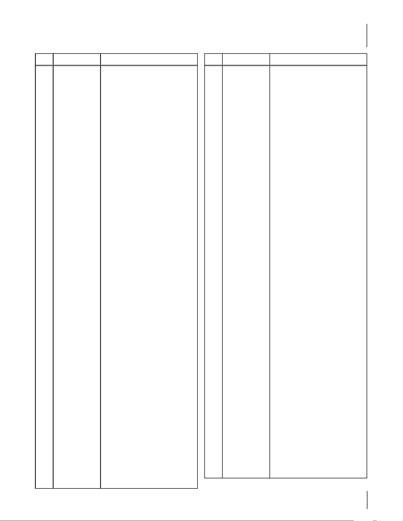
48” Fabricated Deck
27
Ref. Part Number Description
1 01006693P Chute Deector
2 01006748 Chute Bracket
3 01008644 Finger Guard
4 02001235 Micro Chute Bae
5 942- 04417 Blade, 17
6 96606 Hook Retainer Bracket
7 903-04928 Deck Assembly
8 603-04851B PTO Idler Assembly
9 603-04859 Hanger Adjustment Bracket
10 918-3129C Spindle Assembly
11 603-04920A Idler Arm
12 703-07346A Bae
13 703-07664A LH Belt Cover
14 703-07685A RH Belt Cover
15 703-08458 Up-Stop Bracket
16 710-0347 Hex Screw, 3⁄8 x 16 x 1.75
17 710-0859 Hex Screw, 3⁄8-16 x 2.50
18 710-04484 Hex Washer, 5⁄16-18 x .750
19 710-05173A Hex Screw, 3⁄4-16 x 6.00
20 710-0528 Hex Screw, 5⁄16-18 x 1.25
21 710-0599 Hex Washer Screw, 1⁄4-20 x .500
22 710-0604A Hex Washer Screw, 5⁄16-18 x .625
23 710-04605 Hex Washer Screw, 5⁄16-18 x 1.50
24 710-0923 Hex Screw, 5⁄8-18 x 3.00
25 710-3168 Carriage Bolt, 3⁄8-16 x 1.00
26 738-04544 Shoulder Screw, 1.0 x 3.00
27 750-04409 Bearing Spacer, .78 x 1.0 x 1.0425
28 711-3314A Roller Pin, 1⁄2 x 7. 31
29 712-0229 Push Nut, 3⁄8
30 936-0185 Flat Washer, .375 x .738 x .063
31 712- 04065 Flange Lock Nut, 3⁄8-16
32 712-05046 Hex Nut, 1⁄2-13
33 912-0291 Hex Lock Nut, 1⁄4-20
34 912-0641 Hex Nut, M16-1.5
35 912-3019 Hex Nut, 7⁄16-14
36 712- 04327 Flange Lock Nut, 5⁄8-18
37 712-3078 Flange Lock Nut, 3⁄4-16
38 714-3004 Cotter Pin, 3⁄32 x 1.25
39 714-0162 Cotter Pin, 5⁄32 x 1.25
40 916-3020 Retainer Ring
41 917-04074 Deck Adjustment Gear
42 921-04041 Water Nozzle Adapter
Ref. Part Number Description
43 731-05679 Front Roller
44 732-04797 Torsion Spring, 180 x .639 x 2.16 x .12
45 732-04896 Extension Spring, 1.25 x 6.9
46 732-3067 Idler Torsion Spring, 1.10 x 1.3
47 932-3127 Compression Spring, .66 x 1.8
48 734- 04155 Deck Wheel, 5.0
49 936 - 0119 Lock Washer, 5⁄16
50 936 - 0171 Lock Washer, 7⁄16
51 736-0225 Lock Washer, 5⁄8
52 736-0237 Flat Washer, .65 x 1.25 x .075
53 736-0258 Flat Washer, .385 x 1.0 x .135
54 912-3008 Jam Nut, 3⁄8-16
55 736 -04131 Flat Washer, .4375 x 1.75 x .25
56 914-0507 Cotter Pin, 3⁄32 x .75
57 736-3082A Flat Washer, .45 x 1.5 x .172
58 747-05586A Belt Drive Guard
59 737-04003D Deck Water Nozzle
60 737-04345 Grease Fitting, 1⁄4-28 x 3⁄16
61 937-3000 Drive Lube Fitting, 3⁄16
62 941-04089 Cone Bearing, .750
63 938-3056 Shoulder Screw, 1⁄2 x 2.50
64 738-04545 Shoulder Screw, 7⁄16-14 x .687 x 2.443
65 941- 0524A Ball Bearing, .625 x 40 x 12
66 747-05350 Front Hanger Rod
67 747-3188 Mower Support Pin
68 747-3384 Chute Deector Rod
69 748-3065A Spindle Spacer
70 748-3100A Spring Retainer
71 750-05282 Spindle Spacer, .760 x 2.0 x 1.10
72 750-05553 Spacer, .812 x .218
73 950 -3132 Spacer, .88 x .635 x 1.25
74 954-04045 Deck Belt
75 954-04055 PTO Belt
76 756-05042 Idler Pulley
77 756-3089 Pulley
78 756 -3107A Double Pulley
79 941-04091 Bearing Cup, .750
80 921-3018A Oil Seal
81 710 -3178 Carriage Bolt, 3⁄8-16 x .75
82 783-08389 Pulley Cap
83 748-05029A Shoulder Spacer, Idler
48” Fabricated Deck
28
5
72
75
75
72
73
74
73
60
65
61
33
54
45
17
62
25
63
3
59
39
6
53
38
45
54
33
4
24
20
52
41
25
1
25
57
40
32
68
70
71
25
20
10
9
13
11
25
69
16
28
43
16
67
20
66
30
55
31
2
29
26
56
37
23
25
8
5
58
35
19
15
42
34
58
63
47
12
64
13
7
36
50
12
21
50
46
48
12
48
48
18
25
22
51
49
14
44
27
14
76
76
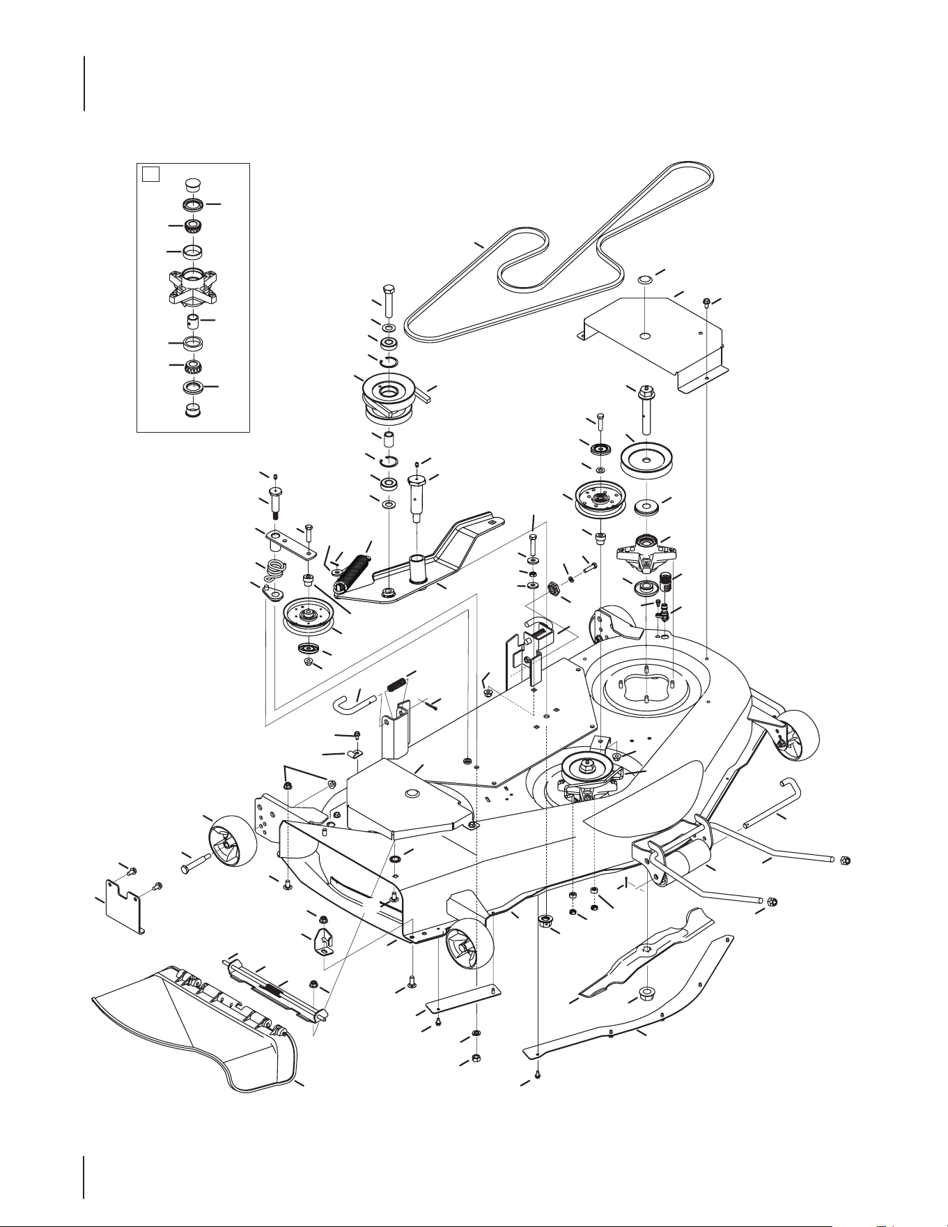
50” Stamped Deck

29
Ref. Part Number Description
1 96606 Hook Retainer Bracket
2 903- 04813B Deck Assembly
3 603-04851B PTO Idler Assembly
4 603-04859 Hanger Adjustment Bracket
5 918-3129C Spindle Assembly
6 603-04920A Idler Arm Assembly
7 703-05546 LH Spindle Shield
8 703-05556 RH Spindle Shield
9 703-08425 Up-Stop Bracket
10 703-08465A Guard
11 703-3279 Chute Deector Stop
12 710-0347 Hex Screw, 3⁄8 x 16 x 1.75
13 710-04484 Hex Washer Screw, 5⁄16-18 x .750
14 783-08389 Pulley Cap
15 710-0528 Hex Screw, 5⁄16-18 x 1.25
16 710-0599 Hex Washer Screw, 1⁄4-20 x .500
17 710-0923 Hex Screw, 5⁄8-18 x 3.00
18 912-3008 Jam Nut, 3⁄8 x 16
19 603-04941 Spindle Bolt, 3⁄4-16 x 4.25
20 710-3168 Carriage Bolt, 3⁄8-16 x 1.00
21 738-04544 Shoulder Screw, 1.0 x 3.00
22 912-0291 Hex Lock Nut, 1⁄4-20
23 711-3314A Roller Pin, 1⁄2 x 7. 31
24 712-0229 Push Nut, 3⁄8
25 712- 04065 Flange Lock Nut, 3⁄8-16
26 712- 05046 Hex Nut, 1⁄2-13
27 731-07487 Deck Wash Nozzle
28 912-3019 Hex Nut, 7⁄16-14
29 712-04327 Flange Lock Nut, 5⁄8-18
30 712-3078 Flange Lock Nut, 3⁄4-16
31 714-3004 Cotter Pin, 3⁄32 x 1.25
32 714-0162 Cotter Pin, 5⁄32 x 1.25
33 916-3020 Retainer Ring
34 917-04074 Deck Adjustment Gear
35 921-04041 Water Nozzle Adapter
36 726-3045 Button Plug
37 731-05679 Front Roller
38 732-04896 Extension Spring, 1.25 x 6.9
Ref. Part Number Description
39 732-3067 Idler Torsion Spring, 1.10 x 1.3
40 932-3127 Compression Spring, .66 x 1.8
41 734- 04155 Deck Wheel, 5.0
42 936 - 0119 Lock Washer, 5⁄16
43 936 - 0171 Lock Washer, 7⁄16
44 738-04278 Shoulder Screw, 1⁄4-20 x 0.50
45 736-0237 Flat Washer, .65 x 1.25 x .075
46 914-0507 Cotter Pin, 3⁄32 x .750
47 736-3050 Flat Washer, .406 x .812 x .051
48 736-0258 Falt Washer, .385 x 1.00 x .135
49 750-05297 Spacer, .256 x .500 x .240
50 937-3000 Drive Lube Fitting, 3⁄16
51 747-05589B Belt Drive Guard
52 938-3056 Shoulder Screw, 1⁄2 x 2.50
53 738-04545 Shoulder Screw, 7⁄16-14 x .687 x 2.443
54 941-0524A Ball Bearing, .625 x 40 x 12
55 759-04047 2-in1 Blade
56 747-05352 Front Lift Rod
57 747-3188 Mower Support Pin
58 748-3065A Spindle Spacer
59 748-3100A Spring Retainer
60 950-3132 Spacer, .88 x .635 x 1.25
61 954-04055 PTO Belt
62 954- 04137A Deck Belt
63 756-05042 Idler Pulley
64 756-3096 Spindle Pulley
65 756-3107A Double Pulley
66 783-04414A Center Skirt
67 783-04415 RH Skirt
68 711- 0 4565 Hinge Pin, .3175 x 14.06
69 631-04070C Chute Deector
70 732-04372 Torsion Spring, .44 x 2.0
71 783-05030 Chute Bracket
72 941-04091 Bearing Cup, .750
73 921-3018A Oil Seal
74 750-04409 Bearing Spacer, .78 x 1.0 x 1.0425
75 941- 04089 Cone Bearing, .750
76 748- 05029A Shoulder Spacer, Idler
50” Stamped Deck
30
11
82
81
81
82
79
80
79
75
9
25
77
72
22
61
78
74
43
65
54
27
15
65
73
43
76
70
49
13
64
62
54
24
60
45
42
50
67
34
10
7
17
83
20
18
3
34
34
4
30
83
32
34
2
68
47
83
5
37
53
34
84
58
52
38
1
12
71
40
6
69
11
34
31
14
21
41
46
35
66
8
76
56
34
44
51
23
16
69
26
39
19
59
29
62
57
48
19
59
59
55
34
63
36
28
85
86
86
87
33
87
54” Fabricated Deck

31
Ref. Part Number Description
1 750-3193 Spacer, .390 x .620 x 3.04
2 01006693P Chute Deector
3 01006748 Chute Deector Bracket
4 01008644 Finger Guard
5 02001235 Micor Chute Bae
6 942-04416 Hi-Lift Blade, 19
7 96606 Hook Retainer Bracket
8 903-04923 Deck Assembly
9 603-04851B PTO Idler Assembly
10 603-04859 Hanger Adjustment Bracket
11 918-3129C Spindle Assembly
12 634 -3159 Wheel, 5.0
13 603-04920A Idler Arm Assembly
14 703- 07687A RH Belt Cover
15 703-07688A LH Belt Cover
16 703-07787 Spindle Reinforcement Plate
17 703-07845A Bae
18 703-08458 Up-Stop Bracket
19 710-0347 Hex Screw, 3⁄8 x 16 x 1.75
20 710-04484 Hex Washer Screw, 5⁄16-18 x .750
21 710-04886 Carriage Bolt, 3⁄8-16 x 2.50
22 710-05173A Hex Screw, 3⁄4-16 x 6.00
23 710-0528 Hex Screw, 5⁄16-18 x 1.25
24 710-0599 Hex Washer Screw, 1⁄4-20 x .500
25 710-0604A Hex Washer Screw, 5⁄16-18 x .625
26 710-04605 Hex Washer Screw, 5⁄16-18 x 1.50
27 710-0923 Hex Screw, 5⁄8-18 x 3.00
28 710-05384 Carriage Screw, 3⁄8-16 x 4.00
29 738-04544 Shoulder Screw, 1.0 x 3.00
30 710-3168 Carriage Bolt, 3⁄8-16 x 1.00
31 711-3314A Roller Pin, 1⁄2 x 7.31
32 712-0229 Push Nut, 3⁄8
33 936-0185 Flat Washer, .375 x .738 x .063
34 712-04065 Flange Lock Nut, 3⁄8-16
35 712-04243 Flex Lock Nut, 1⁄2-13
36 912-0291 Hex Lock Nut, 1⁄4-20
37 912-0641 Hex Nut, M16-1.5
38 912-3019 Hex Nut, 7⁄16-14
39 712- 04327 Flange Lock Nut, 5⁄8-18
Ref. Part Number Description
40 712-3078 Flange Lock Nut, 3⁄4-16
41 714-3004 Cotter Pin, 3⁄32 x 1.25
42 714- 0162 Cotter Pin, 5⁄32 x 1.25
43 916-3020 Retainer Ring
44 917-04074 Deck Adjustment Gear
45 921-04041 Water Nozzle Adapter
46 731-05679 Front Roller
47 732-04797 Torsion Spring, 180 x .639 x 2.16 x .12
48 732-04896 Extension Spring, 1.25 x 6.9
49 732-3067 Idler Torsion Spring, 1.10 x 1.3
50 932-3127 Compression Spring, .66 x 1.8
51 936 - 0119 Lock Washer, 5⁄16
52 936 - 0171 Lock Washer, 7⁄16
53 736-0225 Lock Washer, 5⁄8
54 736-0237 Flat Washer, .650 x 1.250 x .075
55 912-3008 Jam Nut, 3⁄8-16
56 736- 04131 Flat Washer, .4375 x 1.75 x .25
57 914-0507 Cotter Pin, 3⁄32 x .750
58 736-3082A Flat Washer, .45 x 1.5 x .172
59 736-0258 Falt Washer, .385 x 1.00 x .135
60 737-04003D Deck Water Nozzle
61 737-04345 Grease Fitting, 1⁄4-28 x 3⁄16
62 937-3000 Drive Lube Fitting, 3⁄16
63 747-05586A Belt Drive Guard
64 738-04545 Shoulder Screw, 7⁄16-14 x .687 x 2.443
65 941- 0524A Ball Bearing, .625 x 40 x 12
66 747-05350 Front Hanger Rod
67 747-3188 Mower Support Pin
68 747-3384 Chute Deector Rod
69 748-3065A Spindle Deck Spacer
70 748-3100A Retainer Spring
71 750-05282 Spindle Spacer, .760 x 2.0 x 1.10
72 750-05553 Spacer, .812 x .218
73 950 -3132 Spacer, .88 x .635 x 1.25
74 954-04055 PTO Belt
75 954 - 0 4118 Deck Belt
76 756-05042 Idler Pulley
77 756-04459A Pulley
78 756 -3107A Double Pulley
54” Fabricated Deck
Continued on next page

32
Ref. Part Number Description
79 921-3018A Oil Seal
80 750-04409 Bearing Spacer, .78 x 1.0 x 1.0425
81 941-04089 Cone Bearing, .750
82 941- 04091 Bearing Cup, .750
83 710-3178 Carriage Bolt, 3⁄8-16 x .75
84 710 - 0 411 Hex Screw, 3/8-16 x 4.00
85 936-0314 Washer, .375 x .700 x .030
86 783-08389 Pulley Cap
87 748-05029A Shoulder Spacer, Idler
54” Fabricated Deck

33
Page Left Blank Intentionally
34
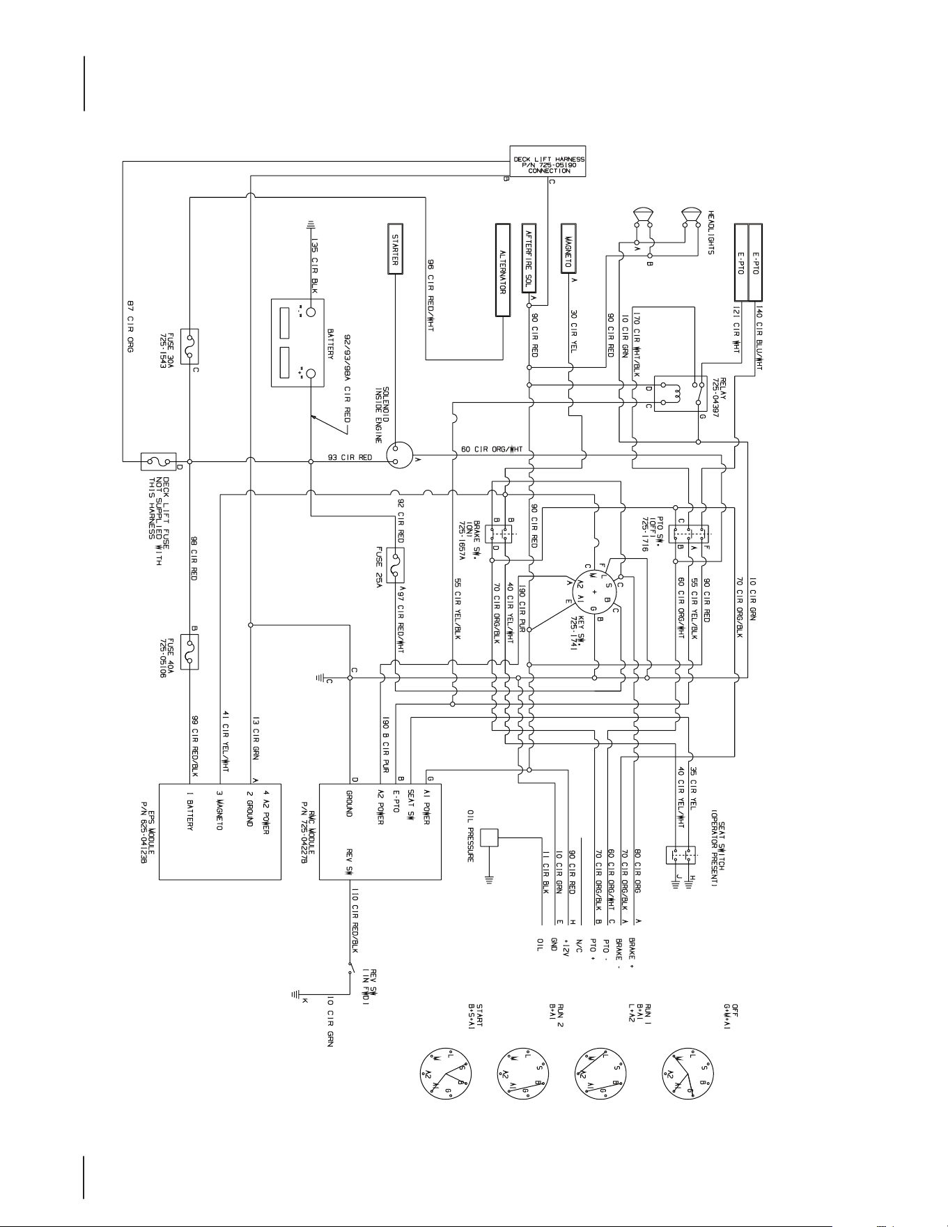
Wiring Schematic
35
TO ENSURE SAFE AND
PROPER OPERATION
OF TRANSMISSION,
ONLY USE CUB CADET
DRIVE SYSTEM
FLUID PLUS.
737-3120 - 1 QUART
737-3121 - 1 GALLON
READ OPERATOR'S
MANUAL
WARNING
S30265
FAS T
S L
O
W
CH OKE ON
FOR OPT IMAL MOWER AND BATTE RY
PE RFORMANCE, RUN AT FULL THROTT LE
TRANSMISSION
RELEASE LEVER
TO ENGAGE TRANSMISSION
PULL LEVER
DOWN
TO RELEASE TRANSMISSION
PULL LEVER
OUT AND UP
LOW GAS
WINDOW
FILL TANK IF GAS
LEVEL IS SHOWN
IN WINDOW
IMPORTANT
I23552
ENGINE ROTATING SCREEN
Clean Debris From Engine Rotati ng
Screen After Each Mowing.
IMPORTANT Perform These
Maintenanc e Items With Engi ne Off.
ENGINE ROTATING SCREENIMPORTANT ENGINE ROTATING SCREEN
ENGINE
ROTATING
SCREEN
LOCATION
ENGINE
ROTATING
SCREEN
LOCATION
• Clean Debris From Engine Rotating Screen After Each Mowing.
• IMPORTANT Perform These Maintenance Items With Engine Off.
I23596
S32517 AC
DANGER
ROTATING BLADES CAUSE
SERIOUS INJURY OR DEATH
WA RNING
• DO NOT MOW WHEN
CHILDREN OR OTHERS
ARE AROUND
• NEVER CARRY
CHILDREN EVEN
WITH BLADE(S) OFF.
• LOOK DOWN AND
BEHIND BEFORE AND
WHILE BACKING.
• MOWING IN REVERSE
IS NOT RECOMMENDED.
• GO UP AND DOWN SLOPES, NOT
ACROSS.
• AVOID SUDDEN TURNS.
• DO NOT OPERATE UNIT WHERE
IT COULD SLIP OR TIP.
• IF MACHINE STOPS GOING
UPHILL, STOP PTO AND BACK
DOWN HILL SLOWLY.
• KEEP SAFETY DEVICES [GUARDS,
SHIELDS, AND SWITCHES] IN
PLACE AND WORKING.
• REMOVE OBJECTS THAT COULD
BE THROWN BY THE BLADES.
• KNOW LOCATION AND FUNCTION
OF ALL CONTROLS.
• BE SURE THE BLADES AND THE
ENGINE ARE STOPPED BEFORE
PLACING HANDS OR FEET NEAR
BLADES.
• BEFORE LEAVING OPERAT OR'S
POSITION, DISENGAGE PTO,
ENGAGE BRAKE LOCK, SHUT
OFF ENGINE AND REMOVE KEY.
AVOID SERIOUS INJURY
OR DEATH
READ OPERATOR'S
MANUAL
STARTING INSTRUCTIONS
1. BE FAMILIAR WITH CONTROLS BEFORE
STARTING ENGINE AND OPERATING.
2. SET CHOKE, MOVE THROTTLE TO MID
POSITION AND DEPRESS BRAKE PEDAL.
3. TURN KEY TO THE START POSITION.
4. AFTER ENGINE STARTS OPEN CHOKE.
STOPPING INSTRUCTIONS
1. DISENGAGE PTO AND SET PARKING
BRAKE: PRESS BRAKE PEDAL
AND LIFT PARKING/CRUISE LEVER.
RELEASE BRAKE PEDAL THEN
RELEASE PARKING/CRUISE LEVER.
2. MOVE THROTTLE CONTROL TO MID
POSITION AND TURN KEY OFF.
PRESS DRIVE PEDAL AND LIFT PARKING
/CRUISE LEVER. RELEASE DRIVE PEDAL
THEN RELEASE PARKING/CRUISE LEVER.
REVERSE CAUTION MODE
NORMAL MOWING
CRUISE CONTROL OPERATION
FOR OPTIMAL MOWER AND BATTERY
PERFORMANCE, RUN AT FULL THROTTLE
YOU MUST DISENGAGE BLADES/PTO,
(POWER TAKE OFF) BEFORE TRAVELING
IN REVERSE.
1. TURN KEY TO REVERSE CAUTION
MODE POSITION.
2. DEPRESS REVERSE PUSH BUTTON.
(RED INDICATOR LIGHT “ON”)
WHEN RED LIGHT IS “ON” MACHINE
CAN BE OPERATED IN REVERSE WITH
MOWER BLADES ENGAGED.
IMPORTANT: MOWING IN REVERSE IS
NOT RECOMMENDED.
3. AFTER RESUMING FORWARD
OPERATION, RETURN KEY TO
“NORMAL MOWING” POSITION.
NOTE: IN BOTH MODES, WHEN
OPERATOR LEAVES SEAT, ENGINE
WILL STOP UNLESS PARKING BRAKE
IS SET AND BLADES ARE DISENGAGED.
Operation Of This Equipment May Create Sparks
That Can Start Fires Around Dry Vegetation. A
Spark Arrestor May Be Required. The Operator
Should Contact Local Fire Agencies For Laws Or
Regulations Relating To Fire Prevention
Requirements.
OPERATING MODES
IMPORTANTIMPORTANT
ENGINE ROTATING SCREEN
• CLEAN DEBRIS FROM ENGINE ROTATING
SCREEN AFTER EACH MOWING.
• IMPORTANT PERFORM THESE
MAINTENANCE ITEMS WITH ENGINE OFF.
LO
2
3
4
5
6
7
8
9
HI
GT 2042
SHAF T DRIVE
V-TWIN •
GT 2042
SHAF T DRIVE
V-TWIN
•
X46987
GT 2042
DECK ROUTING
www.cubcadet. com
COMMON PARTS ITEM NUMBER
ACCESSORIES ITEM NUMBER
942-04374 (X2)
954-04055(Pto)
954-0645A(Deck)
759-3336 (X2)
KH-47-883-03-S1
KH-52-050-02-S1
KH-24-050-13-S
58 oz / 10W-30
12 Volts
19A40003100
19A40021100
19A40022100
19A40020100
490-241-0026
190-307-100
490-900-M059
490-290-0013
490-850-0008
490-850-0005
490-900-0045
Blade(s)
Deck belt(s)
Spark Plug(s)
Air Filter
Oil Filter
Fuel Filter
Amount of oil & weight
Battery Voltage
Bagger
Mulch Kit
Dozer Blade
Snow Thrower
Tire Chains
Weight Kit
Extra Weight
Riding Mower Cover
Oil Siphon
Blade Removal Tool
Oil Filter Wrench
GT 2042
MTD CONSUMER GROUP INC.
This equipment meets U.S. EPA EVP
regulations for 2013 model year.
EVP Family: DMTDPNHEQRP1
EMISSION CONTROL INFORMATION
X46245
®
MTD
CONSUMER GROUP INC.
This equipment meets U.S. EPA EVP
regulations for 2014 model year.
EVP Family: EMTDPNHEQRP1
EMISSION CONTROL INFORMATION
X46884
®
GT 2050
SHAF T DRIVE
V-TWIN •
GT 2050
SHAF T DRIVE
V-TWIN •
X46989
GT 2050
DECK ROUTING
www.cubcadet.com
COMMON PARTS ITEM NUMBER
ACCESSORIES ITEM NUMBER
759-04047 (X3)
954-04055(Pto)
954-04137A(Deck)
759-3336 (X2)
KH-47-883-03-S1
KH-52-050-02-S1
KH-24-050-13-S
58 oz / 10W-30
12 Volts
19A40004100
190-193-100
19A40022100
19A40020100
490-241-0026
190-307-100
490-900-M059
490-290-0013
490-850-0008
490-850-0005
490-900-0045
Blade(s)
Deck belt(s)
Spark Plug(s)
Air Filter
Oil Filter
Fuel Filter
Amount of oil & weight
Battery Voltage
Bagger
Mulch Kit
Dozer Blade
Snow Thrower
Tire Chains
Weight Kit
Extra Weight
Riding Mower Cover
Oil Siphon
Blade Removal Tool
Oil Filter Wrench
COLORS
FORMAT #
COMMENTS / REPLACES
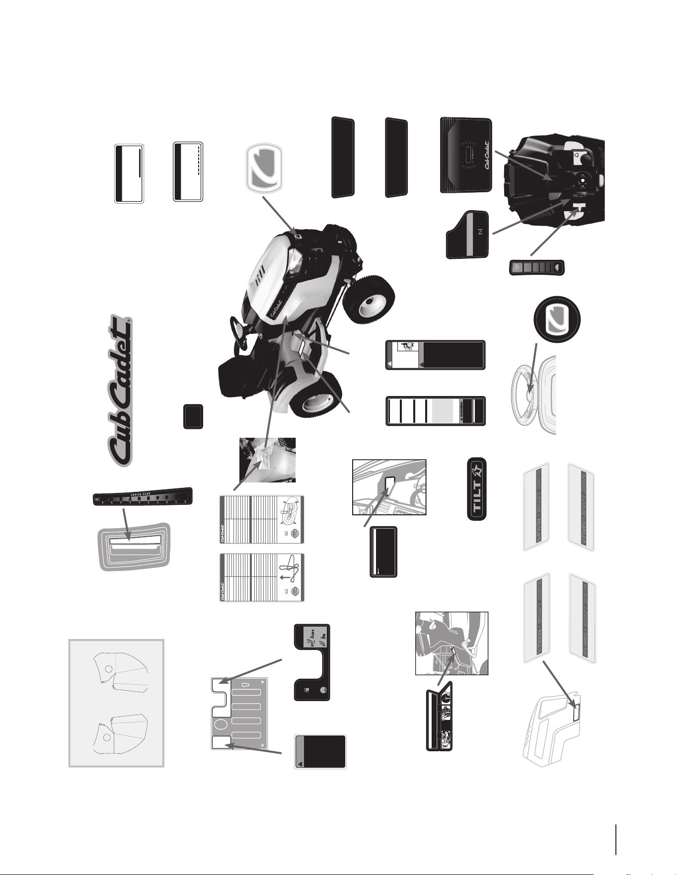
777F12296
BLACK
ITEM DESCRIPTION
GT 2050
UNDER HOOD
UNDER HOOD
777S30265
REAR HITCH AREA
777I23553
777I23552
Place On Shield
Between Engine
and Battery
777I23596
Place On Left
Side Panel Over
Curve Aligned
With Top Angle
777D19516
777X46987
777D16298
Place On
Steering Cap
Place On Seat Bracket
On Flat Surface Closest
To Model Plate
777X46245
777X46884
777D15414
Centered On Rear Of
Bumper Covering Hole
777D19517
777D15340
Centered On Rear
777I23551
Eff. from 12.31.13
Eff. from 1.1.14
777X44663
REFERENCE ONLY
RIGHT
777X44662
LEFT
777D19522
777D19523
777X46989
Centered On Bumper
777I23556
Place On Steering
Column Handle
777D16533
777I23481
777I23527
777I25220
777D19525
Centered On Bumper
777D19524
777S33928
Facing
Operator
777S32517
Facing
Operator
(GT 2050) (GT 2042)
GT2000 Labels
36
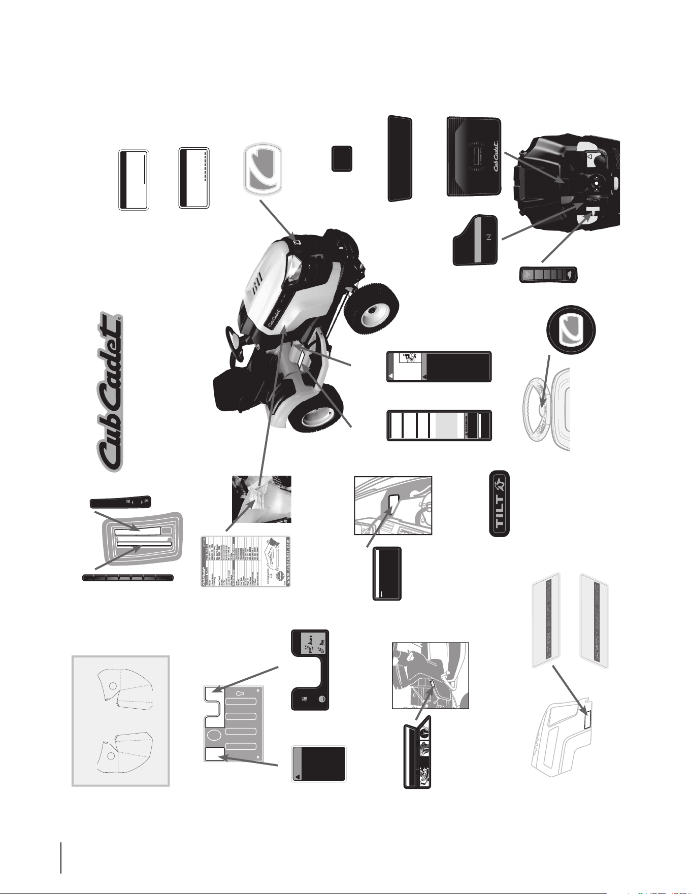
GT2148 Labels
TO ENSURE SAFE AND
PROPER OPERATION
OF TRANSMISSION,
ONLY USE CUB CADET
DRIVE SYSTEM
FLUID PLUS.
737-3120 - 1 QUART
737-3121 - 1 GALLON
READ OPERATOR'S
MANUAL
WARNING
S30265
FAS T
S LOW
CH OKE ON
FOR OPT IMAL MOWER AND BATTE RY
PE RFORMANCE, RUN AT FULL THROTT LE
TRANSMISSION
RELEASE LEVER
TO ENGAGE TRANSMISSION
PULL LEVER
DOWN
TO RELEASE TRANSMISSION
PULL LEVER
OUT AND UP
LOW GAS
WINDOW
FILL TANK IF GAS
LEVEL IS SHOWN
IN WINDOW
IMPORTANT
I23552
ENGINE ROTATING SCREEN
Clean Debris From Engi ne Rotating
Screen After Each Mowing.
IMPORTANT Perform These
Maintenance Items With Engi ne Off.
ENGINE ROTATING SCREENIMPORTANT ENGINE ROTATING SCREEN
ENGINE
ROTATING
SCREEN
LOCATION
ENGINE
ROTATING
SCREEN
LOCATION
• Clean Debris From Engine Rotating Screen After Each Mowing.
• IMPORTANT Perform These Maintenance Items With Engine Off.
I23596
S32517 AC
DANGER
ROTATING BLADES CAUSE
SERIOUS INJURY OR DEATH
WARNING
• DO NOT MOW WHEN
CHILDREN OR OTHERS
ARE AROUND
• NEVER CARRY
CHILDREN EVEN
WITH BLADE(S) OFF.
• LOOK DOWN AND
BEHIND BEFORE AND
WHILE BACKING.
• MOWING IN REVERSE
IS NOT RECOMMENDED.
• GO UP AND DOWN SLOPES, NOT
ACROSS.
• AVOID SUDDEN TURNS.
• DO NOT OPERATE UNIT WHERE
IT COULD SLIP OR TIP.
• IF MACHINE STOPS GOING
UPHILL, STOP PTO AND BACK
DOWN HILL SLOWLY.
• KEEP SAFETY DEVICES [GUARDS,
SHIELDS, AND SWITCHES] IN
PLACE AND WORKING.
• REMOVE OBJECTS THAT COULD
BE THROWN BY THE BLADES.
• KNOW LOCATION AND FUNCTION
OF ALL CONTROLS.
• BE SURE THE BLADES AND THE
ENGINE ARE STOPPED BEFORE
PLACING HANDS OR FEET NEAR
BLADES.
• BEFORE LEAVING OPERAT OR'S
POSITION, DISENGAGE PTO,
ENGAGE BRAKE LOCK, SHUT
OFF ENGINE AND REMOVE KEY.
AVOID SERIOUS INJURY
OR DEATH
READ OPERATOR'S
MANUAL
STARTING INSTRUCTIONS
1. BE FAMILIAR WITH CONTROLS BEFORE
STARTING ENGINE AND OPERATING.
2. SET CHOKE, MOVE THROTTLE TO MID
POSITION AND DEPRESS BRAKE PEDA L.
3. TURN KEY TO THE START POSITION.
4. AFTER ENGINE STARTS OPEN CHOKE.
STOPPING INSTRUCTIONS
1. DISENGAGE PTO AND SET PARKING
BRAKE: PRESS BRAKE PEDAL
AND LIFT PARKING/CRUISE LEVER.
RELEASE BRAKE PEDAL THEN
RELEASE PARKIN G/CRUISE LEVER.
2. MOVE THROTTLE CONTROL TO MID
POSITION AND TURN KEY OFF.
PRESS DRIVE PEDAL AND LIFT PARKING
/CRUISE LEVER. RELEASE DRIVE PEDAL
THEN RELEASE PARKING/CRUISE LEVER.
REVERSE CAUTION MODE
NORMAL MOWING
CRUISE CONTROL OPERATION
FOR OPTIMAL MOWER AND BATTERY
PERFORMANCE, RUN AT FULL THROTTLE
YOU MUST DISENGAGE BLADES/PTO,
(POWER TAKE OFF) BEFORE TRAVELING
IN REVERSE.
1. TURN KEY TO REVERSE CAUTION
MODE POSITION.
2. DEPRESS REVERSE PUSH BUTTON.
(RED INDICATOR LIGHT “ON”)
WHEN RED LIGHT IS “ON” MACHINE
CAN BE OPERATED IN REVERSE WITH
MOWER BLADES ENGAGED.
IMPORTANT: MOWING IN REVERSE IS
NOT RECOMMENDED.
3. AFTER RESUMING FORWARD
OPERAT ION, RETURN KEY TO
“NORMAL MOWING” POSITION.
NOTE: IN BOTH MODES, WHEN
OPERATOR LEAVES SEAT, ENGINE
WILL STOP UNLESS PARKING BRAKE
IS SET AND BLADES ARE DISENGAGED.
Operation Of This Equipment May Create Sparks
That Can Start Fires Around Dry Vegetation. A
Spark Arrestor May Be Required. The Operator
Should Contact Local Fire Agencies For Laws Or
Regulations Relating To Fire Prevention
Requirements.
OPERATING MODES
IMPORTANTIMPORTANT
ENGINE ROTATING SCREEN
• CLEAN DEBRIS FROM ENGINE ROTATING
SCREEN AFTER EACH MOWING.
• IMPORTANT PERFORM THESE
MAINTENANCE ITEMS WITH ENGINE OFF.
GT 2148
SHAFT DRIVE
V-TWIN •
GT 2148
SHAFT DRIVE
V-TWIN •
GT 2148
CI
RTCELE
TFIL KCED
ESIAR
KCED
REWOL
K
CED
c
e
D cir
t
c
el
E
e
tare
p
O
oT th
g
i
e
H t
f
iL
k tn
e
m
tsujdA
fiL kceD cirtcelE esiaR oP tsehgiH ehT oT t .noitis
t
h
gi
e
H
g
ni
t
t
u
C
teS iL
k
c
e
D
ci
rt
c
e
lE
r
ew
oL . t
f
g
ni
t
t
u
C
ne
s
o
h
C
oT
.
n
o
i
t
i
s
o
P
LO 1 2 3 4 5 6 HI
777X44663
REFERENCE ONLY
RIGHT
777X44662
LEFT
777S30265
REAR HITCH AREA
777I23553
777I23596
Place On Left
Side Panel Over
Curve Aligned
With Top Angle
UNDER HOOD
777D19520
777D19521
777I23556
Place On Steering
Column Handle
UNDER HOOD
777I23552
Place On Shield
Between Engine
and Battery
Place On
Steering Cap
777D16533
777S33928
Facing
Operator
777S32517
Facing
Operator
777I23481
777I23527
777I25220
777D16298
777D15414
Centered On Rear Of
Bumper Covering Hole
777D15340
Centered On Rear
777I23555
777X46990
777I23479
Centered On Bumper
777D19526
MTD
CONSUMER GROUP INC.
This equipment meets U.S. EPA EVP
regulations for 2013 model year.
EVP Family: DMTDPNHEQRP1
EMISSION CONTROL INFORMATION
X46245
®
MTD CONSUMER GROUP INC.
This equipment meets U.S. EPA EVP
regulations for 2014 model year.
EVP Family: EMTDPNHEQRP1
EMISSION CONTROL INFORMATION
X46884
®
Place On Seat Bracket
On Flat Surface Closest
To Model Plate
777X46245
777X46884
Eff. from 12.31.13
Eff. from 1.1.14
37
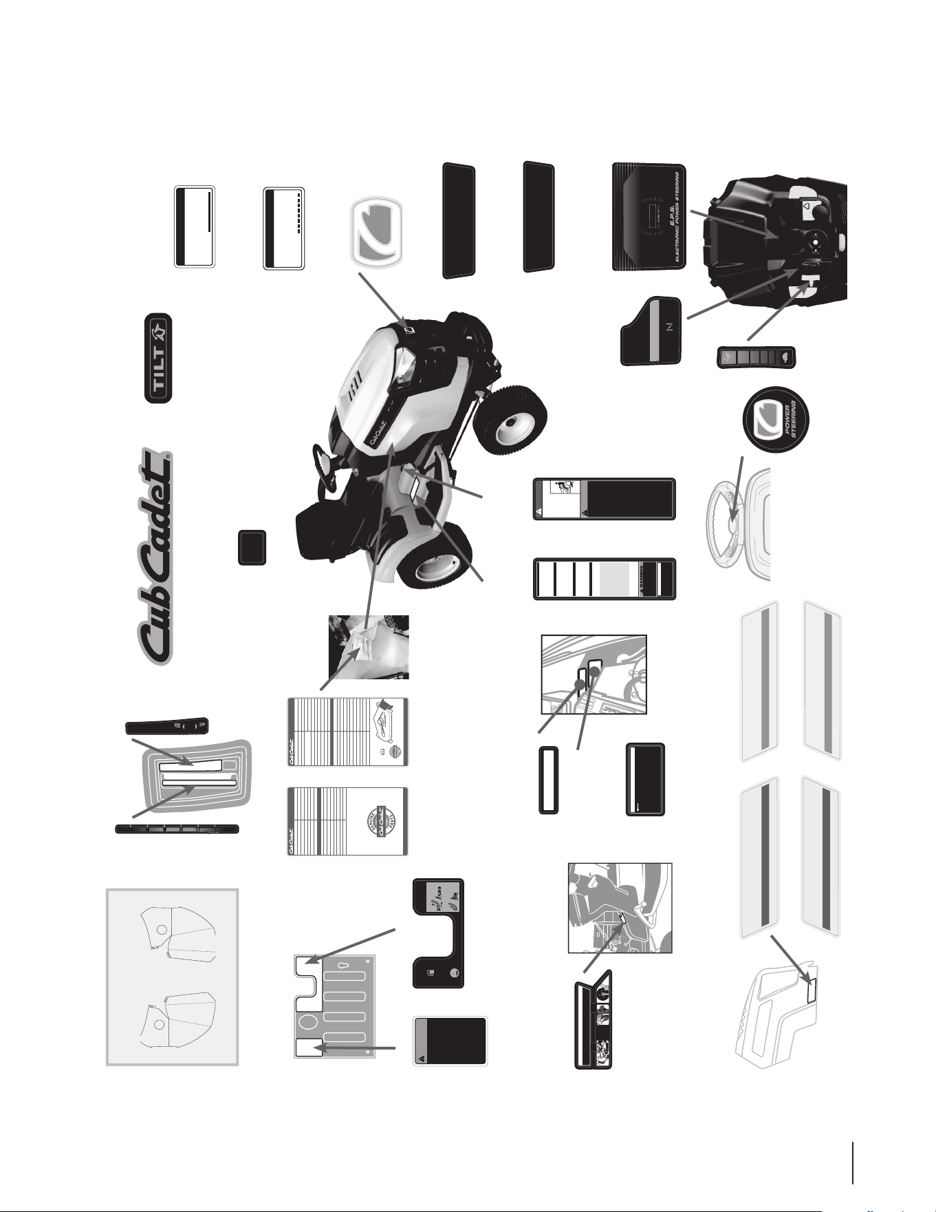
GTX2100 Labels
UNDER HOOD
TO ENSURE SAFE AND
PROPER OPERATION
OF TRANSMISSION,
ONLY USE CUB CADET
DRIVE SYSTEM
FLUID PLUS.
737-3120 - 1 QUART
737-3121 - 1 GALLON
READ OPERATOR'S
MANUAL
WARNING
S30265
FAS T
S LOW
CH OKE ON
FOR OPT IMAL MOWER AND BATTE RY
PE RFORMANCE, RUN AT FULL THROTT LE
TRANSMISSION
RELEASE LEVER
TO ENGAGE TRANSMISSION
PULL LEVER
DOWN
TO RELEASE TRANSMISSION
PULL LEVER
OUT AND UP
LOW GAS
WINDOW
FILL TANK IF GAS
LEVEL IS SHOWN
IN WINDOW
ENGINE ROTATING SCREENIMPORTANT ENGINE ROTATING SCREEN
ENGINE
ROTATING
SCREEN
LOCATION
ENGINE
ROTATING
SCREEN
LOCATION
• Clean Debris From Engine Rotating Screen After Each Mowing.
• IMPORTANT Perform These Maintenance Items With Engine Off.
I23596
S32517 AC
DANGER
ROTATING BLADES CAUSE
SERIOUS INJURY OR DEATH
WA RNING
• DO NOT MOW WHEN
CHILDREN OR OTHERS
ARE AROUND
• NEVER CARRY
CHILDREN EVEN
WITH BLADE(S) OFF.
• LOOK DOWN AND
BEHIND BEFORE AND
WHILE BACKING.
• MOWING IN REVERSE
IS NOT RECOMMENDED.
• GO UP AND DOWN SLOPES, NOT
ACROSS.
• AVOID SUDDEN TURNS.
• DO NOT OPERATE UNIT WHERE
IT COULD SLIP OR TIP.
• IF MACHINE STOPS GOING
UPHILL, STOP PTO AND BACK
DOWN HILL SLOWLY.
• KEEP SAFETY DEVICES [GUARDS,
SHIELDS, AND SWITCHES] IN
PLACE AND WORKING.
• REMOVE OBJECTS THAT COULD
BE THROWN BY THE BLADES.
• KNOW LOCATION AND FUNCTION
OF ALL CONTROLS.
• BE SURE THE BLADES AND THE
ENGINE ARE STOPPED BEFORE
PLACING HANDS OR FEET NEAR
BLADES.
• BEFORE LEAVING OPERAT OR'S
POSITION, DISENGAGE PTO,
ENGAGE BRAKE LOCK, SHUT
OFF ENGINE AND REMOVE KEY.
AVOID SERIOUS INJURY
OR DEATH
READ OPERATOR'S
MANUAL
STARTING INSTRUCTIONS
1. BE FAMILIAR WITH CONTROLS BEFORE
STARTING ENGINE AND OPERATING.
2. SET CHOKE, MOVE THROTTLE TO MID
POSITION AND DEPRESS BRAKE PEDAL.
3. TURN KEY TO THE START POSITION.
4. AFTER ENGINE STARTS OPEN CHOKE.
STOPPING INSTRUCTIONS
1. DISENGAGE PTO AND SET PARKING
BRAKE: PRESS BRAKE PEDA L
AND LIFT PARKING/CRUISE LEVER.
RELEASE BRAKE PEDAL THEN
RELEASE PARKIN G/CRUISE LEVER.
2. MOVE THROTTLE CONTROL TO MID
POSITION AND TURN KEY OFF.
PRESS DRIVE PEDAL AND LIFT PARKING
/CRUISE LEVER. RELEASE DRIVE PEDAL
THEN RELEASE PARKING/CRUISE LEVER.
REVERSE CAUTION MODE
NORMAL MOWING
CRUISE CONTROL OPERATION
FOR OPTIMAL MOWER AND BATTERY
PERFORMANCE, RUN AT FULL THROTTLE
YOU MUST DISENGAGE BLADES/PTO,
(POWER TAKE OFF) BEFORE TRAVELING
IN REVERSE.
1. TURN KEY TO REVERSE CAUTION
MODE POSITION.
2. DEPRESS REVERSE PUSH BUTTON.
(RED INDICATOR LIGHT “ON”)
WHEN RED LIGHT IS “ON” MACHINE
CAN BE OPERATED IN REVERSE WITH
MOWER BLADES ENGAGED.
IMPORTANT: MOWING IN REVERSE IS
NOT RECOMMENDED.
3. AFTER RESUMING FORWARD
OPERAT ION, RETURN KEY TO
“NORMAL MOWING” POSITION.
NOTE: IN BOTH MODES, WHEN
OPERATOR LEAVES SEAT, ENGINE
WILL STOP UNLESS PARKING BRAKE
IS SET AND BLADES ARE DISENGAGED.
Operation Of This Equipment May Create Sparks
That Can Start Fires Around Dry Vegetation. A
Spark Arrestor May Be Required. The Operator
Should Contact Local Fire Agencies For Laws Or
Regulations Rela ting To Fire Prevention
Requirements.
OPERATING MODES
IMPORTANTIMPORTANT
ENGINE ROTATING SCREEN
• CLEAN DEBRIS FROM ENGINE ROTATING
SCREEN AFTER EACH MOWING.
• IMPORTANT PERFORM THESE
MAINTENANCE ITEMS WITH ENGINE OFF.
GTX
2154
SHA F T DRIVE
•V-TWI N
•
GTX 2154
SHA F T DRIVE
•V-TWI N •
X47233
GTX 2154
DECK ROUTING
www.cubcadet.com
COMMON PARTS ITEM NUMBER
ACCESSORIES ITEM NUMBER
942-04416 (X3)
02005018-X (X3)
954-04055(Pto)
954-04118(Deck)
759-3336 (X2)
KH-47-883-03-S1
KH-52-050-02-S1
KH-24-050-13-S
58 oz / 10W-30
12 Volts
19A40004100
19A70023100
19A40022100
19A40020100
490-241-0026
190-307-100
490-900-M059
490-290-0013
490-850-0008
490-850-0005
Blade(s)
Extreme Blade(s)
Deck belt(s)
Spark Plug(s)
Air Filter
Oil Filter
Fuel Filter
Amount of oil & weight
Battery Voltage
Bagger
Mulch Kit
Dozer Blade
Snow Thrower
Tire Chains
Weight Kit
Extra Weight
Riding Mower Cover
Oil Siphon
Blade Removal Tool
GTX 2154
CIRTCEL
E
TF
I
L
KCED
ESI
AR
KCED
REWOL
K
CE
D
ceD
c
ir
t
cel
E
e
ta
rep
O
oT thgieH
t
f
iL
k
tn
emtsuj
d
A
fiL k
c
eD cirtcelE esiaR
oP tsehgiH ehT oT t .noit
is
thgieH gnittuC teS iL
k
ceD cirtcelE rewoL . tf
g
nitt
u
C nesohC
o
T
.
n
oi
t
isoP
REVISIONS
MBER
REV DESCRIPTION DATE REVISED BY EC
12/09/10 C. Ruhf
l musat, narrow ed by .125” 12/05/2011 C. Ruhf
MTD PRODUCTS INC
ABEL COLORS MUST MATCH MTD
7
7I23555
LO 1 2 3 4 5 6 HI
777I23552
Place On Shield
Between Engine
and Battery
777I25030
Place On Shield
Between Engine and
Battery Above I23552
IMPORTANT
I23552
ENGINE ROTATING SCREEN
Clean Debris From Engine Rotati ng
Screen After Each Mowing.
IMPORTANT Perform These
Maintenance Items With Engine Off.
DO NOT J UMP START B ATTE RY
I25030
X47200
GTX 2100
www.cubcadet.com
COMMON PARTS ITEM NUMBER
ACCESSORIES ITEM NUMBER
759-3336 (X2)
KH-47-883-03-S1
KH-52-050-02-S1
KH-24-050-13-S
58 oz / 10W-30
12 Volts
19A40022100
19A40020100
490-241-0026
190-307-100
490-900-M059
490-290-0013
490-850-0008
490-850-0005
Spark Plug(s)
Air Filter
Oil Filter
Fuel Filter
Amount of oil & weight
Battery Voltage
Dozer Blade
Snow Thrower
Tire Chains
Weight Kit
Extra Weight
Riding Mower Cover
Oil Siphon
Blade Removal Tool
GTX 2100
SHA F T DRIVE
•V-T WIN •
GTX 2100
SHA F T DRIVE
•V-T WIN •
GTX 2100
UNDER HOOD
777S30265
REAR HITCH AREA
777I23553
777I23596
Place On Left
Side Panel Over
Curve Aligned
With Top Angle
777D19519
777D15308
777D15309
777D19518
Place On
Steering Cap
777D15407
777S33928
Facing
Operator
777S32517
Facing
Operator
777I23481
777I23527
777I25220
777D16298
777D15414
Centered On Rear Of
Bumper Covering Hole
777D15340
Centered On Rear
777I23555
777X47233
777I23479
Centered On Bumper
777D19527
Centered On Bumper
777D15413
777I23556
Place On Steering
Column Handle
777X47200
777X46245
(GTX 2154)
777X46884
(GTX 2100 & GTX 2154)
MTD CONSUMER GROUP INC.
This equipment meets U.S. EPA EVP
regulations for 2013 model year.
EVP Family: DMTDPNHEQRP1
EMISSION CONTROL INFORMATION
X46245
®
MTD CONSUMER GROUP INC.
This equipment meets U.S. EPA EVP
regulations for 2014 model year.
EVP Family: EMTDPNHEQRP1
EMISSION CONTROL INFORMATION
X46884
®
Place On Seat Bracket
On Flat Surface Closest
To Model Plate
Eff. from 12.31.13
Eff. from 1.1.14
777X44663
REFERENCE ONLY
RIGHT
777X44662
LEFT
38
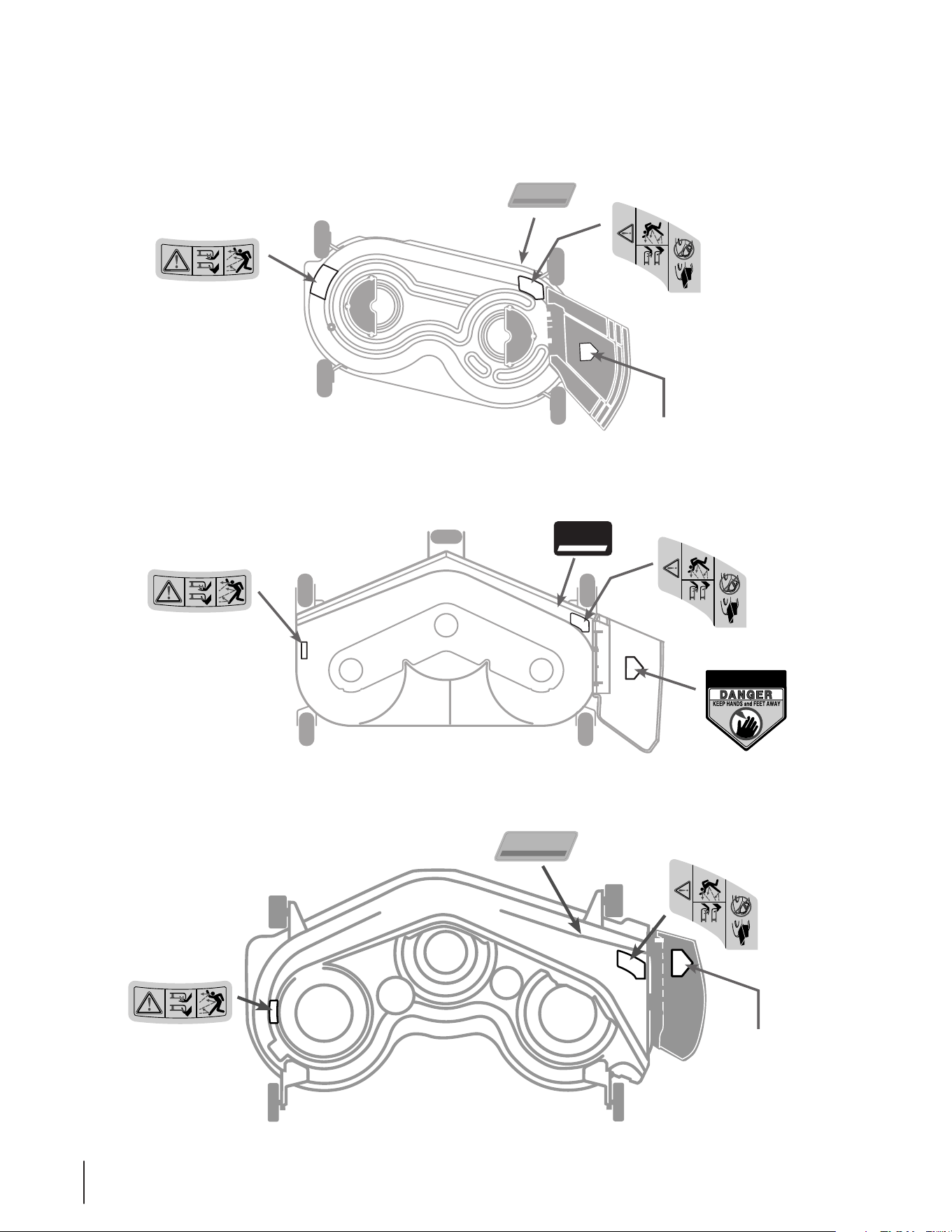
Deck Labels
REF: Chute Label
Applied By Manufacturer
777S35297
777S35296
777D15397
Place On Front
Of The Deck
42
INCH
DECK
TO REDUCE THE RISK OF INJURY,DO NOT
OPERATE UNLESS DISCHARGE COVER OR
GRASS CATCHER IS IN ITS PROPER PLACE.
IF DAMAGED, REPLACE IMMEDIATELY.
777S35298
777D19177
S35297
777S35296
777S35297
S35297
48
FABRICATED
D19177
50
INCH
DECK
SIG NATUR E CUT™
777S35296
REF: Chute Label
Applied By Manufacturer
777S35297
S35297
777D15400
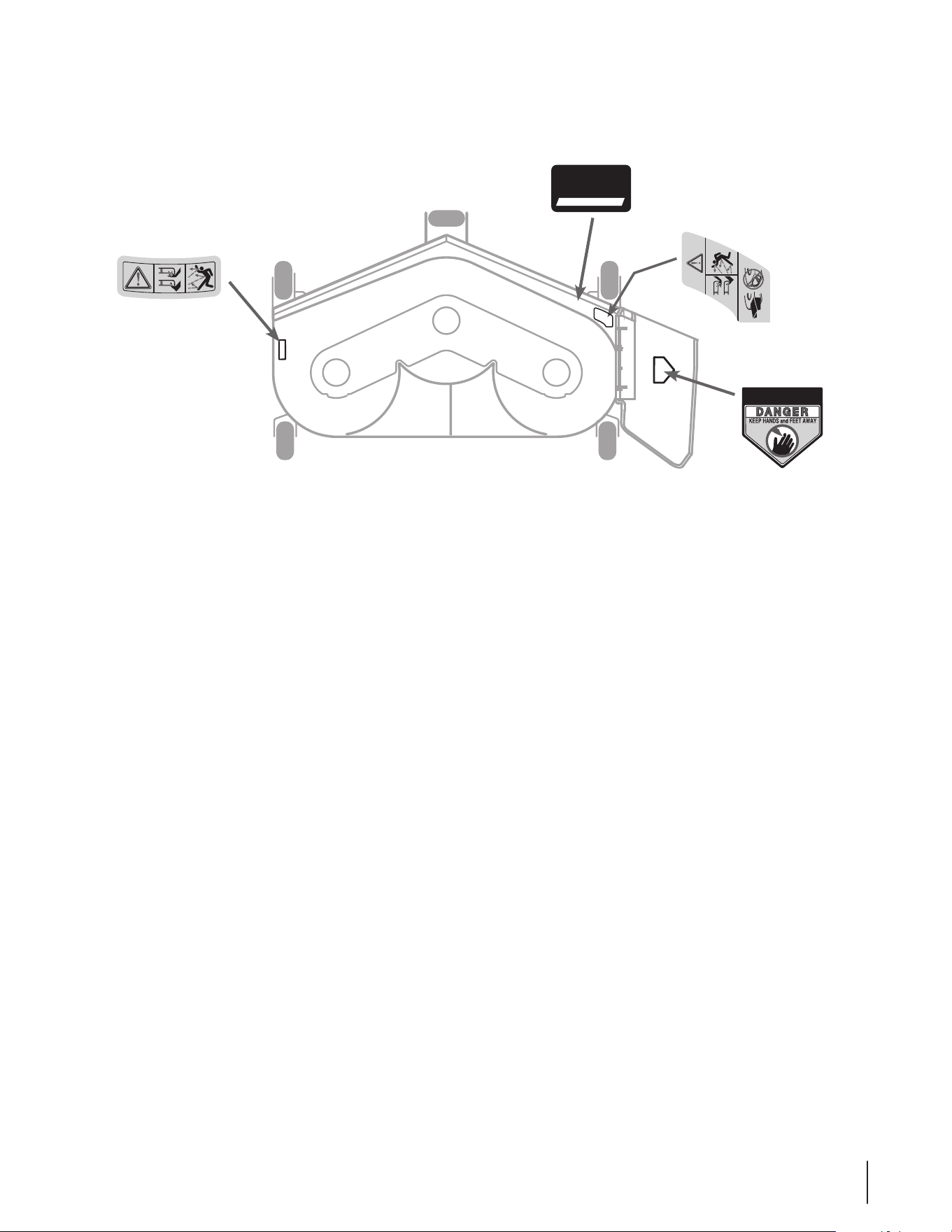
39
777S35298
777D19178
TO REDUCE THE RISK OF INJURY,DO NO T
OPERATE UNLESS DISCHARGE COVER OR
GRASS CATCHER IS IN ITS PROPER PLACE .
IF DAMAGED, REPLACE IMMEDIATELY .
777S35296
777S35297
S
3
5
2
9
7
54
FABRIC ATED
D19178
Deck Labels
40
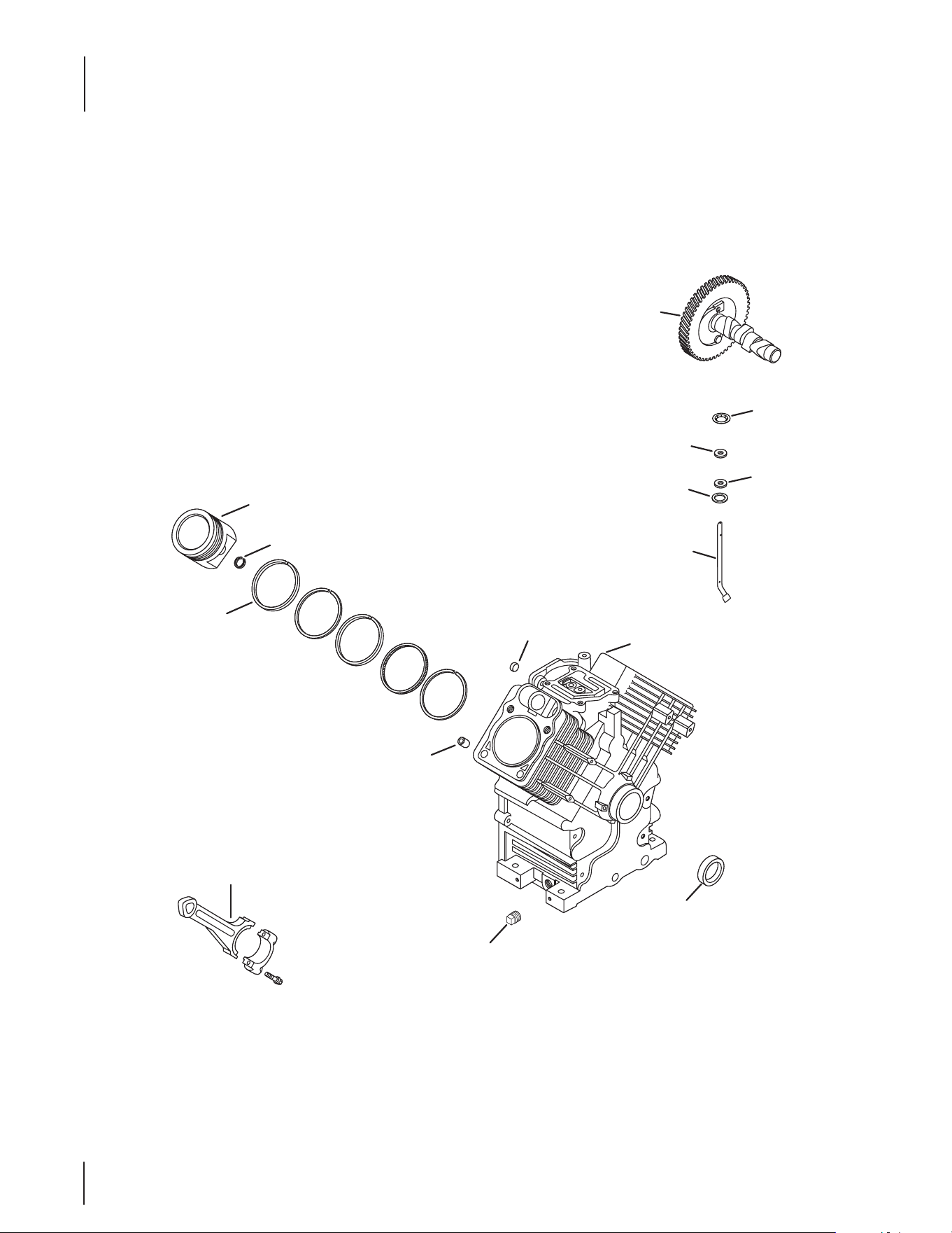
Kohler CH680-3072 Crankcase
1
14
3
5
4
2
Service with Short
Block or Mini-Block
9
10
6
8
12
11
13
7

41
Kohler CH680-3072 Crankcase
Ref.
Part Number Description
1 KH-24 -012-10-S Camshaft Kit
2 KH-M-931010-S Flat Washer, 9 MM
3 KH-28-032-09-S Governor Cross Shaft Seal
4 KH-24-468-15-S Flat Washer, 11⁄32
5 KH-24-144-38-S Governor Cross Shaft
6 KH-25-139-57-S Square Headd Pipe Plug, 3⁄8
7 KH-24- 032-19 -S Oil Seal (Helix Lip)
8 KH-24-067-30-S Connecting Rod Assembly
9 KH-24-380-16-S Locating Pin
10 KH-52-139-09-S Cup Plug
11 KH-24-018-01-S Piston Pin Retainer
12 KH-24-108-18-S Ring Set (Std)
— KH-24-108-19-S Ring Set (.08)
— KH-24-108-20-S Ring Set (.25)
— KH-24-108-21-S Ring Set (.50)
13 KH-24-874-42-S Piston Assembly Kit w/ Ring (Std.)
— KH-24-874-43-S Piston Assembly Kit w/ Ring Set (.08)
— KH-24-874-44-S Piston Assembly Kit w/Ring Set (.25)
— KH-24-874-45-S Piston Assembly Kit w/ Ring Set (.5)
14 KH-24-018-09-S Ring Retainer
42
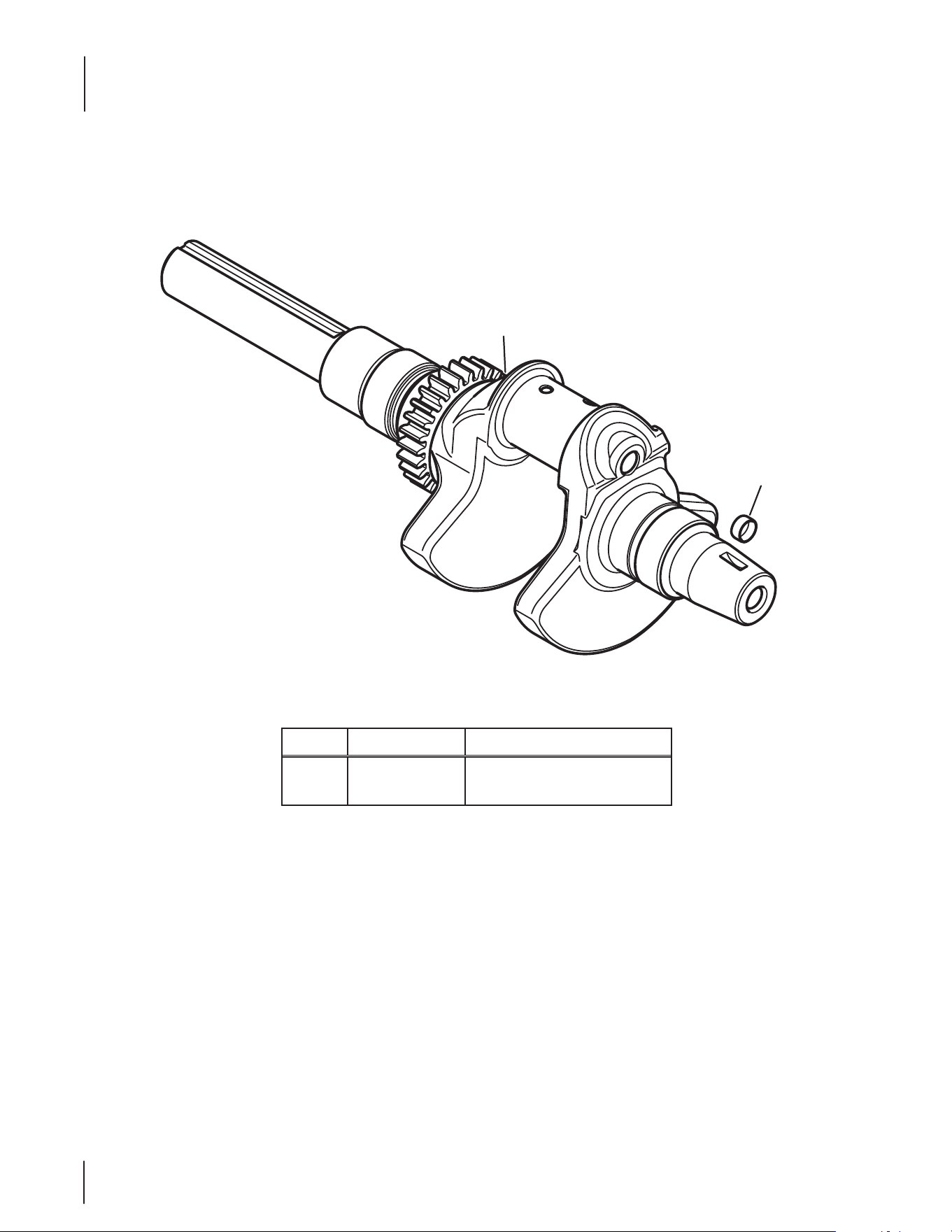
Kohler CH680-3072 Crankshaft
Ref.
Part Number Description
1 KH-24-014-383-S Crankshaft (Includes 2)
2 KH-52-139-09-S Cup Plug
1
2
43
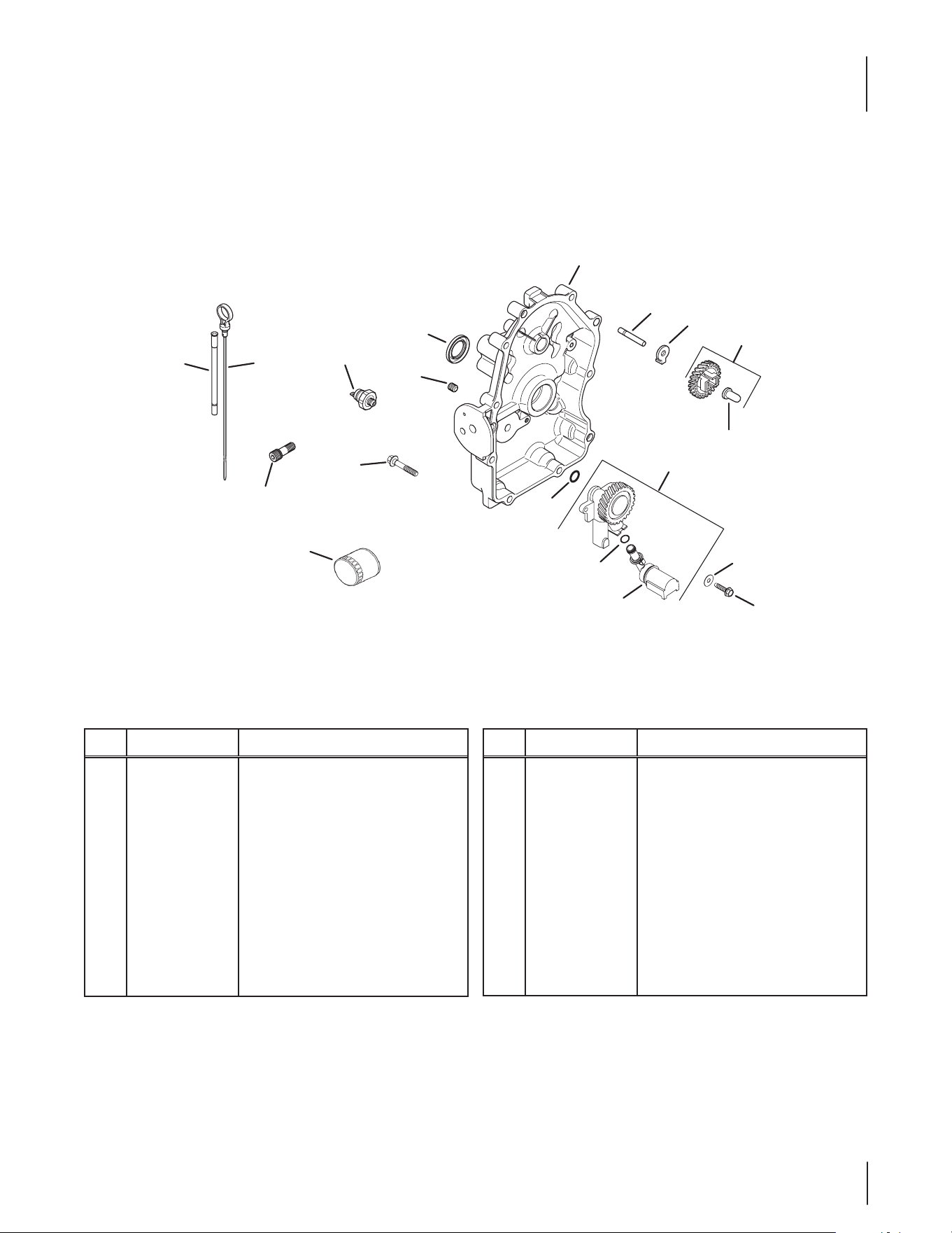
Kohler CH680-3072 Oil Pan/Lubrication
Ref.
Part Number Description
1 KH-24-755-121-S Dipstick/Dipstick Tubes Kit
2 KH-24-038-10 -S Dipstick
3 KH-25-032-06-S Oil Seal
4 KH-25-139- 60-S Countersink Pipe Plug, 1⁄8
5 KH-25- 099-27-S Oil Pressure Switch
6 KH-24 - 086 -17-S Flange Screw, M8 x 1.25 x 45
7 KH-24- 009-85-S Closure Plate Assembly
8 KH-12-144- 02 Governor Gear Shaft
9 KH-24-448-02-S Locking Tab
10 KH-24-043-12 Governor Gear Kit w/ Pin
Ref.
Part Number Description
11 KH-12-380 -01 Governor Regulating Pin
12 KH-24-153-08 O-Ring
13 KH-24-393-53-S Oil Pump Assembly Kit
14 KH-24-153-01 Oil Pick-Up O-Ring
15 KH-24-381-04 Oil Pick-Up
16 KH-X-25-53 Flat Washer, 1⁄4 x 5⁄8
17 KH-25-086-401-S Thread Forming Screw
18 KH-52-050-02-S Oil Filter
19 KH-24-136 -01 Oil Filter Nipple
NS KH-25 -086-17-S Screw
2
7
18
6
19
4
5
3
1
13
15
12
17
16
12
11
10
9
8
44
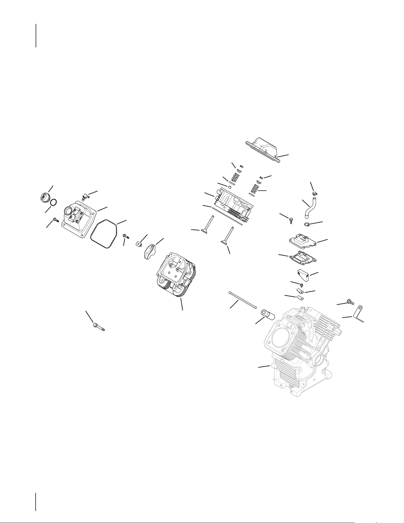
Kohler CH680-3072 Head/Valve/Breather
14
24
27
23
26
21
25
17
20
19
18
11
25
12
15
13
31
30
Crankcase
29
28
33
32
9
3
1
2
4
5
6
7
35
34
8
22
10

45
Kohler CH680-3072 Head/Valve/Breather
Ref.
Part Number Description
1 KH-24-153-32-S O-Ring
2 KH-24-227-02-S Oil Fill Cap Assembly
3 KH-M-651030-S Flange Screw, M6 x 1.0 x 30
4 KH-25-294-11-S 90 Degree Fitting Kit
5 KH-24-559-10-S Valve Cover-Fuel Pump Kit
6 KH-24-153-30-S Vlave Cover O-Ring
7 KH-M-640034-S Flange Screw, M6 x 1.0 x 34
8 KH-24-016-01 Exhaust Valve (Std)
— KH-24-016-02 Exhaust Valve (.25)
9 KH-24-841-02-S Cylinder Head Gasket Kit (C17-22)
10 KH-24-318-144-S #1 Cylinder Head Assembly Kit
11 KH-25-032-14-S Valve Stem Seal
12 KH-24-089-02 Valve Spring
13 KH-12-755-03 Retainer Kit
14 KH-24-755-141-S Valve Cover-Plain Kit
15 KH-25-173-28-S Valve Spring Cap
16 K H -235011-S Spring Retainer
17 KH-25-086-396-S Thread Forming Screw
18 KH-25-237-08-S Band Spring Hose Clamp
19 KH-24-326-89-S Breather Hose
Ref.
Part Number Description
20 KH-25-237-31-S Hose Clamp (KM)
21 KH-24-041-67-S Breather Gasket
22 KH-24-017-01 Intake Valve (Std)
— KH-24-017-02 Intake Valve (.25)
23 KH-M-0545010 Flange Screw, M5 x .8 x 10
24 KH-24-402-03 Breather Reed
25 KH-24-033-01 Breather Assembly Kit
26 KH -24 - 050 -11-S Breather Filter
27 KH-66-018-04-S Reed Retainer
28 KH-25-086-395-S Thread Forming Screw
29 KH-25-445-03-S Lift Strap
30 KH-25-351-11-S Hydraulic Valve Lifter
31 K H -24 - 411- 05 Push Rod
32 KH-62-086-08-S Flange Screw, M10 x 1.5 x 90
33 KH-24 -318-150-S #2 Cylinder Head Assembly Kit
34 KH-24-755-66 Valve Train Kit
— KH-25-186-01 Rocker Arm
35 KH-24-599-02-S Rocker Arm Pivot
NS KH-24-755-147-S Cylinder Head Hardware Kit
46
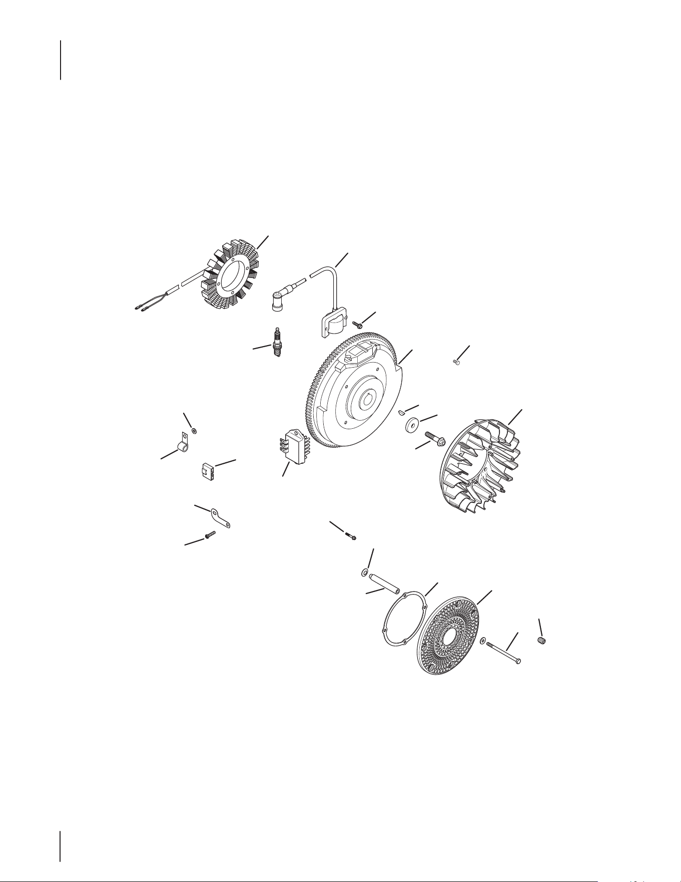
Kohler CH680-3072 Ignition/Electrical
1
5
24
4
3
2
6
7
8
9
16
14
15
10
12
13
17
18
20
22
21
23
19
47
Kohler CH680-3072 Ignition/Electrical
Ref.
Part Number Description
1 KH-28-085-02-S 25 Amp Stator Assembly Kit
2 KH-24-584-45-S Module Ignition Kit (CDI Fixed)
3 KH-25-086-399-S Thread Forming Screw
4 KH-24-025-55-S Flywheel
5 KH-X-42-15 Key, 3⁄16 x 5⁄8
6 KH-12- 468- 03 Flat Washer, 13⁄32
7 KH-25-086-361-S Flange Screw, M10 x 1.5 x 45
8 KH-24-157-11-S Fan
9 KH-24-162-39-S Grass Screen
10 KH-M-603100 Cap Screw, M6 x 1.0 x 99.5
11 KH-X-25-53 Flat Washer, 1⁄4 x 5⁄8
12 KH-25-086-43 Socket Set Screw, #10-24 x 1⁄4
13 N/A Support Ring
14 KH-24-112-14 Spacer
15 K H -24 - 468 -11 Spring Washer, 10 MM
16 KH-25-086-157-S Hex Flange Hi-Lo Screw
17 KH-24-126-137-S Ground Strap Bracket
18 KH-25-403-21-S Rectier Regulator
19 KH-25-155-41-S Connector
20 KH-235173 Cable Clip
21 KH-X-25-63 Flat Washer, 1⁄4 x 1⁄2
22 KH-12-132-02-S Spark Plug (Std.)
23 KH-24- 086-17-S Flange Screw, M8 x 1.25 x 45
24 KH-25-086-91-S Washer Head Tap Screw, #8-18 X 1⁄2
NS KH-25-454-07-S Tie
NS KH-24-176-188-S Wiring Harness Assembly
NS 719-3096 Drive Shaft Adapter
NS KH-54-755-03-S 25 Amp Conversion Kit
NS KH-25-086-412-S Thread Forming Screw

48
Kohler CH680-3072 Blower Housing & Baffles
2
1
3
4
10
7
6
5
8
13
10
12
11
10
9
7
14
12

49
Kohler CH680-3072 Blower Housing & Baffles
Ref.
Part Number Description
1 N/A Flange Screw, M6 x 1.0 x 10
2 KH-24-063-13-S Ducted Air-Oil Filter Bae
3 KH-24 -063-12-S Ducted Air-Starter Bae
4 KH-25-086-400-S Thread Forming Screw
5 KH-24-063-93-S Valley Bae, #1 Cylinder
6 KH-24-063-85-S Cylinder Bae Kit, #1 Side
7 KH-25-086-397-S Thread Forming Screw
8 KH-24-063-94-S Valley Bae, #2 Cylinder
9 KH-24-063-88-S Cylinder Bae Kit, #2 Side
10 KH-24-146 -59-S Backing Plate Kit
11 KH-24- 027-119-S Blower Housing Assembly Kit
12 KH-25-154-13-S Bae Mounting Clip
13 KH-25-086-398-S Thread Forming Screw
14 KH-25-755-20-S Access Panel Kit
NS KH-25-086-396-S Thread Forming Screw
NS KH-25-086-406-S Thread Forming Screw
NS KH-25-086-426-S Thread Forming Screw
50
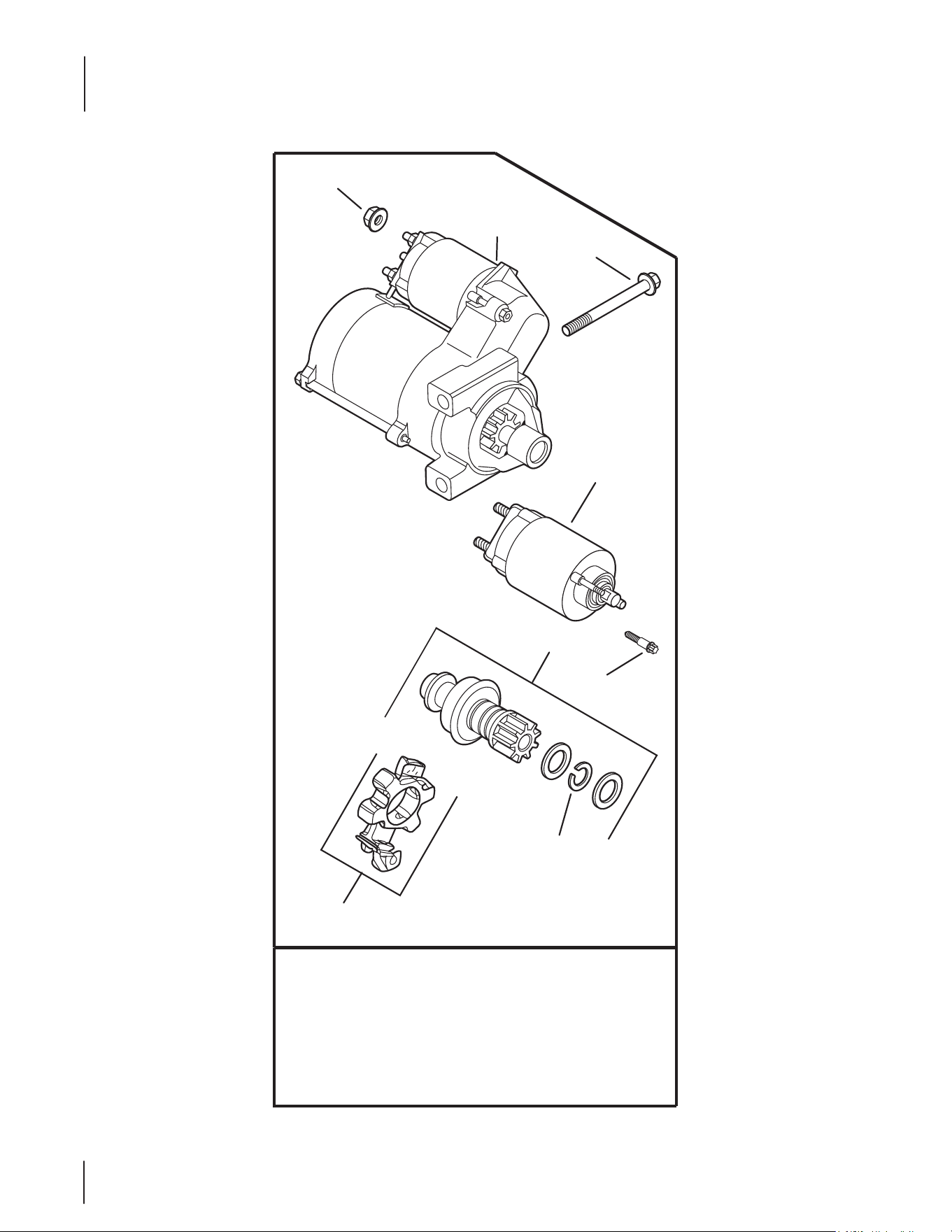
Kohler CH680-3072 Starting System
KH-25-098-11-S (Delco)
KH-25-098-11-S (Delco)
KH-25-098-11-S (Delco)
2
3
1
8
7
5
6
4

51
Kohler CH680-3072 Starting System
Ref.
Part Number Description
1 712-3086 Flange Nut, M8 x 1.25
2 KH -25 - 0 98 -11-S Electric Starter (Solenoid Shift)
3 KH-M-851080-S Flange Screw, M8 x 1.25 x 80
4 KH-25-435-06-S Solenoid Kit
5 KH-25-755-33-S Starter Pinion Kit
6 KH -25 - 0 86 -113-S External Torx Head Screw
7 KH-25-141-05-S Retaining Ring
8 KH-25-221-01-S Brush Holder Kit
* Service starter components according to the part number
printed on the starter. Starter components are NOT inter-
changeable. To replace complete Starter Assembly, order Part
Number 25 098 09-S.
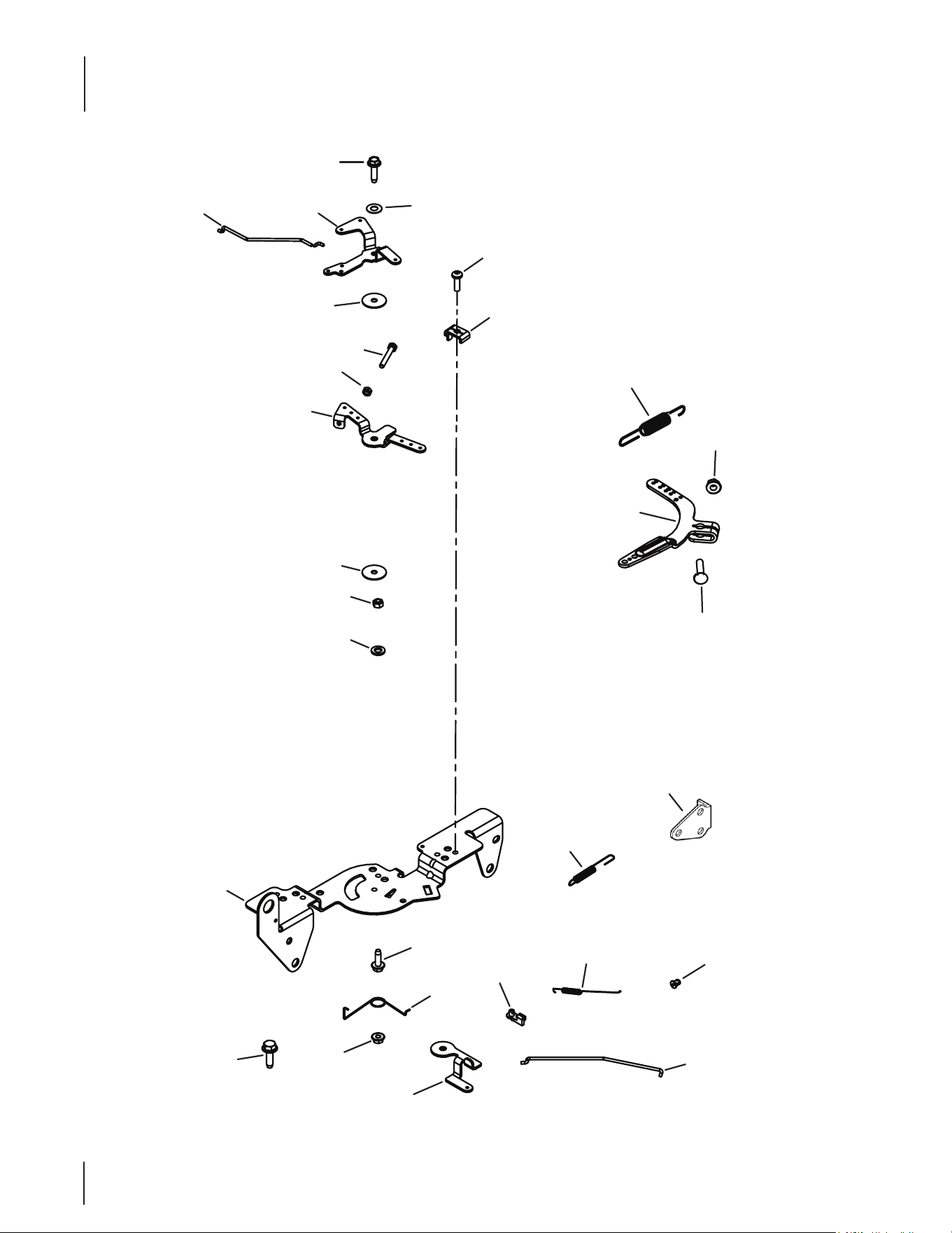
52
Kohler CH680-3072 Engine Controls
4
3
6
5
7
10
9
8
2
1
24
25
26
27
12
11
7
16
15
2
1
13
17
19
18
20
21
22
23

53
Kohler CH680-3072 Engine Controls
Ref.
Part Number Description
1 KH-25-086-398-S Thread Forming Screw
2 KH-12-237-01 Cable Clamp
3 KH-25-086-399-S Thread Forming Screw
4 KH-41-468-03 Spring Washer, 1⁄4
5 KH-24-079-21-S Choke Linkage
6 KH-24-090-05 Choke Lever
7 KH-24-468-01 Flat Washer, 5.5 MM
8 KH-M-401030 Cap Screw, M4 x .7 x 30
9 KH-M-446030-S Nut, M4 x 0.7
10 KH-24-090-13 Throttle Control Lever
11 KH-M-541050-S Flange Nut, M5 x .8
12 KH-X-20-1 Spring Lock Washer, 1⁄4
13 KH-24-126-176-S Control Bracket
14 KH-24-089-03 Choke Return Spring
15 KH-M-547050-S Lock Nut, M5 x .8
16 KH-25-086-396-S Thread Forming Screw
17 KH-24-090-65-S Throttle Actuator Lever
18 KH-25-158-11 Throttle Linkage Bushing
19 KH-24-089-01 Linkage Spring
20 KH-25-158- 08 Linkage Retaining Bushing
21 KH-24-079-01 Throttle Linkage
22 KH-24-126-04-S Bracket
23 KH-24-089-51-S Throttle Limiter Spring
24 KH-24-211-03-S Bolt, M6 x 1.0 x 25
25 KH-24-090-57-S Governor Lever
26 KH-M-641060-S Flange Nut, M6 x 1.0
27 KH-24-089-48-S Governor Spring (Purple)
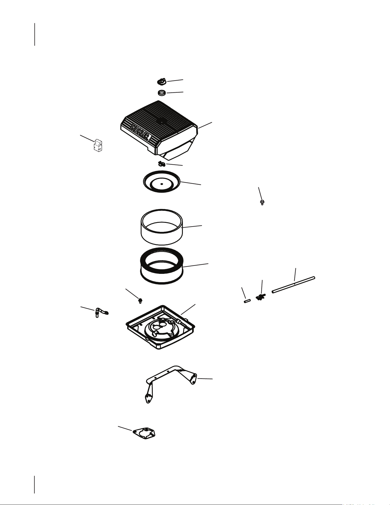
54
Kohler CH680-3072 Air Intake/Filtration
2
1
3
4
5
6
7
8
9
10
11
12
17
13
15
16
14
55
Kohler CH680-3072 Air Intake/Filtration
Ref.
Part Number Description
1 KH-25-341-04-S Cover Knob
2 KH-24-153-20-S O-Ring
3 KH-24- 096 -133-S A/C Cover
4 KH-24-032-03 Inner Air Cleaner Seal
5 KH-12-100-01 Wing Nut
6 KH-24-096-01 Inner Air Cleaner Cover
7 KH-47-883-03-S1 Pre-cleaner Element (Low)
8 KH-47-883-03-S1 Air Cleaner Element
9 KH-24-294-27-S Evaporative Hose Connector
10 KH-24-326-131-S Evap Hose
11 KH-24-126-130-S Air Cleaner Base Bracket
12 KH-24-041-06 Air Cleaner Base Gasket
13 KH-25-086-400-S Thread Forming Screw
14 KH-25-326-08-S Evaporative Hose, 20”
15 KH-25-155-51-S Evaporative Connector
16 KH-25-173-33-S Masking Cap
17 KH-24-094-84-S Air Cleaner Base Kit
NS KH-54-755-01-S Knob Kit w/ Seal
NS KH-24-294-27-S Evaporative Hose Connector
NS KH-24-086-53-S Flange Thread Screw, M6 x 1.0 x 16
NS KH-24-126-206-S Air Cleaner Bracket
NS KH-24-164-93-S Intake Manifold Kit
NS KH-24-041-53-S Carburetor Gasket
NS KH-24-153-27-S Intake Port O-Ring
NS KH-M-651040-S Flange Screw, M6 x 1.0 x 40
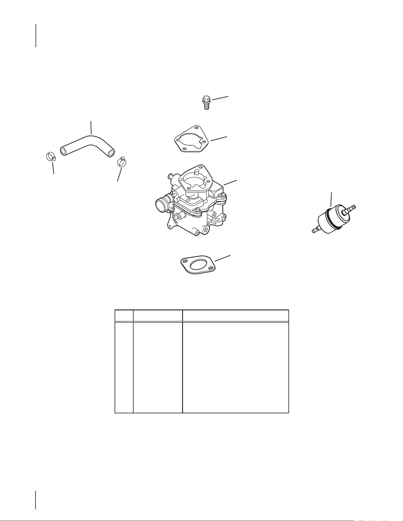
56
Kohler CH680-3072 Fuel System
Ref.
Part Number Description
1 KH -25 -111- 81-S Low Permeation Fuel Hose, 24"
2 KH-25-237-31-S Hose Clamp (KM)
3 KH-24-853-59-S Carburetor Kit w/ Gaskets
4 KH-25-086 -124 -S Flange Screw, M6 x 1.0 x 25
5 KH-24-041-06 Air Cleaner Base Gasket
6 KH-24- 041-17 Carburetor Gasket
7 KH-24- 050-13-S Fuel Filter
NS KH -X-22-11 Internal Tooth Lock Washer, 1⁄4
NS KH-24-518-24-S Ground Lead
1
2
2
3
5
4
6
7
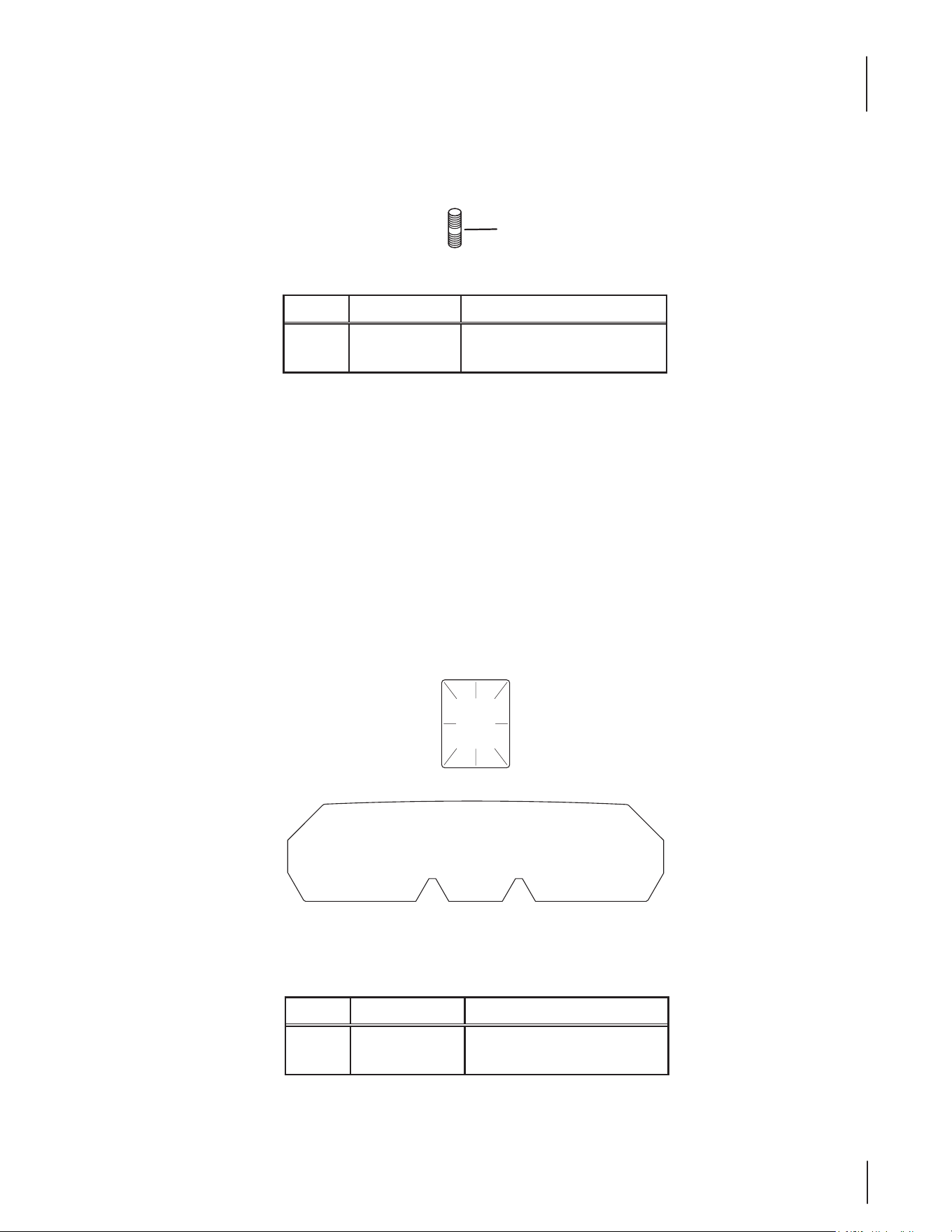
57
Kohler CH680-3072 Miscellaneous
Kohler CH680-3072 Labels
Ref.
Part Number Description
1 KH-25-072-24-S Stud, M8 x 1.25 x 33
— KH-47-154-01-S Cable Clip
Ref.
Part Number Description
1 K H -2 5 -113 -39 -S Clear Laminate Decal
2 KH-24-113-200-S Oil Sentry Decal
1
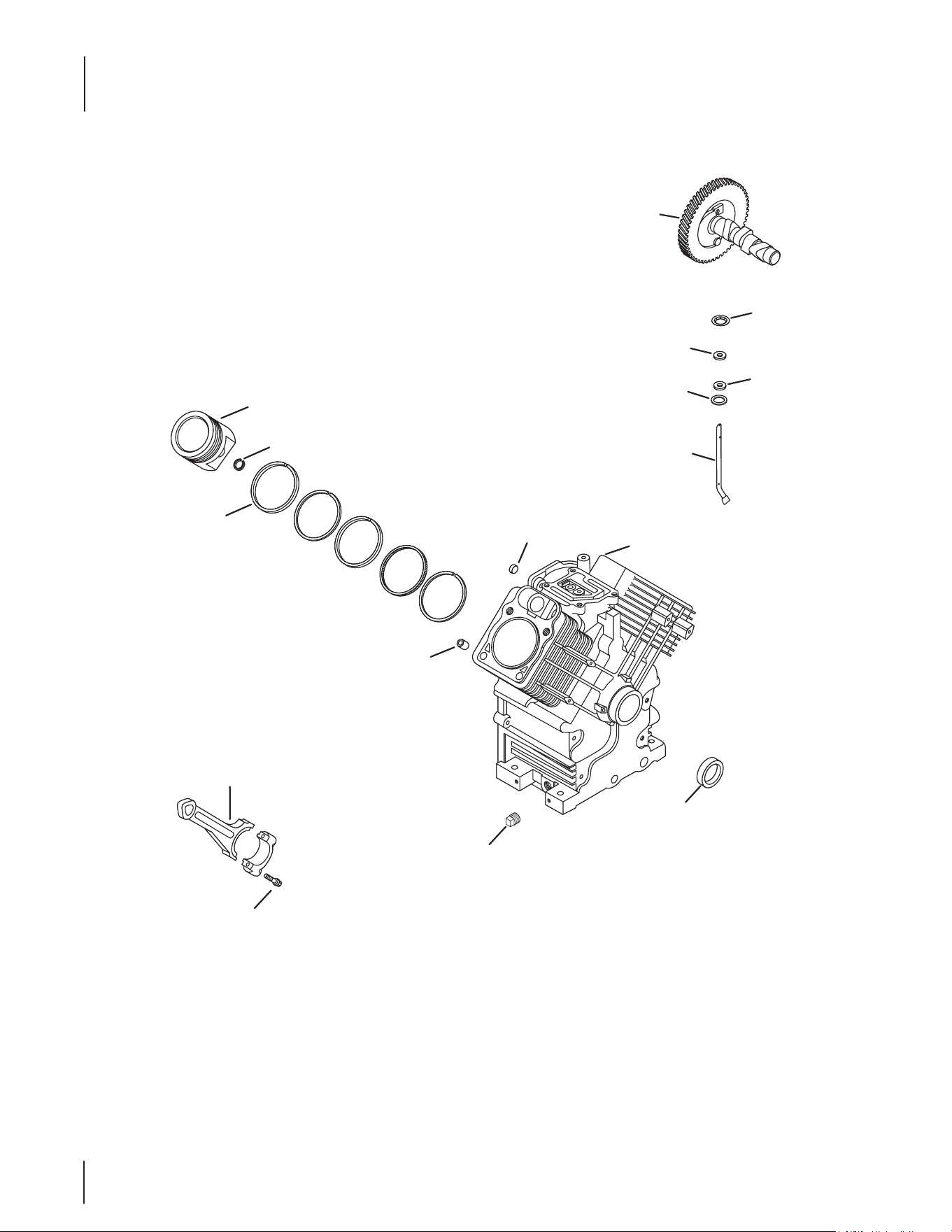
58
Kohler CH640-3123 Crankcase
1
14
3
5
4
2
Service with Short
Block or Mini-Block
9
10
6
8
12
11
13
7
15
59
Kohler CH640-3123 Crankcase
Ref.
Part Number Description
1 KH-24 -012-10-S Camshaft Kit
2 KH-M-931010-S Flat Washer, 9 MM
3 KH-28-032-09-S Governor Cross Shaft Seal
4 KH-24-468-15-S Flat Washer, 11⁄32
5 KH-24-144-38-S Governor Cross Shaft
6 KH-25-139-57-S Square Headd Pipe Plug, 3⁄8
7 KH-24- 032-19 -S Oil Seal (Helix Lip)
8 KH-24-067-34-S Connecting Rod Assembly
9 KH-24-380-16-S Locating Pin
10 KH-52-139-09-S Cup Plug
11 KH-24-018-01-S Piston Pin Retainer
12 KH-24-108-18-S Ring Set (Std)
— KH-24-108-19-S Ring Set (.08)
— KH-24-108-20-S Ring Set (.25)
— KH-24-108-21-S Ring Set (.50)
13 KH-24-874-54-S Piston Kit w/ Ring Set (Standard)
— KH-24-874-55-S Piston Kit w/ Ring Set (.08)
— KH-24-874-56-S Piston Kit w/Ring Set (.25)
— KH-24-874-57-S Piston Kit w/ Ring Set (.50)
14 KH-24-018-09-S Ring Retainer
15 KH-25-086-452-S Rod Bolts Kit
NS KH-25-357-14-S Camshaft Lubricant

60
Kohler CH640-3123 Crankshaft
Ref.
Part Number Description
1 KH-24-014-383-S Crankshaft (Includes 2)
2 KH-52-139-09-S Cup Plug
1
2
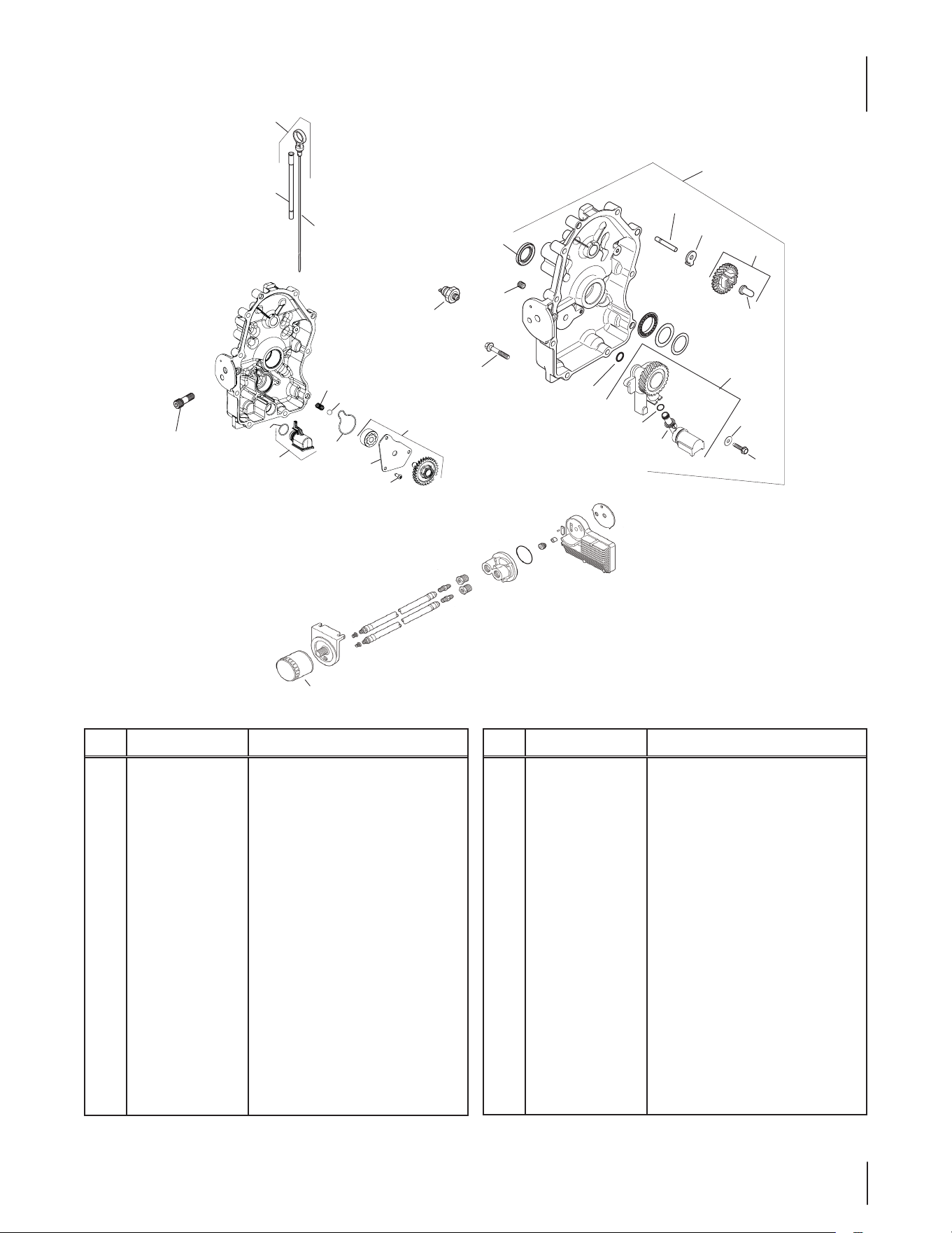
61
Kohler CH640-3123 Oil Pan/Lubrication
Ref.
Part Number Description
1 KH-24-755-121-S Dipstick/Dipstick Tubes Kit
2 KH-24-038-10 -S Dipstick
3 KH-25-032-06-S Oil Seal
4 KH-25-139- 60-S Countersink Pipe Plug, 1/8
5 KH-25- 099-27-S Oil Pressure Switch
6 KH-25 -086-17-S Screw
— KH-24- 086-17-S Flange Screw, M8 x 1.25 x 45
7 KH-24-009-215-S Closure Plate Assembly
8 KH-12-144- 02 Governor Gear Shaft
9 KH-24-448-02-S Locking Tab
10 KH-24-043-12 Governor Gear Kit w/ Pin
11 KH-12-380 -01 Governor Regulating Pin
12 KH-24-153-08 O-Ring
13 KH-24-393-53-S Oil Pump Assembly Kit
14 KH-24-153-01 Oil Pick-Up O-Ring
Ref.
Part Number Description
15 KH-24-381-04 Oil Pick-Up
16 KH-X-25-53 Flat Washer, 1/4 x 5/8
17 KH-25-086-401-S Thread Forming Screw
18 KH-52-050-02-S Oil Filter
19 KH-24-136 -01 Oil Filter Nipple
20 KH-24-089-74-S Compression Spring
21 KH-24-153-33-S Oil Pump Cover Seal
22 KH-24 -381-13-S Oil Pick-Up Assembly
23 KH-24-153-34-S Oil Pick-Up O-Ring
24 KH-24-393-70-S Oil Pump Assembly
25 KH-24- 096 -151-S Oil Pump Cover
26 KH-25-086-414-S Button Head Screw
27 KH-25-194-03-S Pressure Relief Ball
28 KH-24-123-25-S Dipstick Tube
3
4
6
5
10
9
11
8
12
13
14
15
16
17
19
7
2
18
1
28
20
24
25
26
27
22
23
21
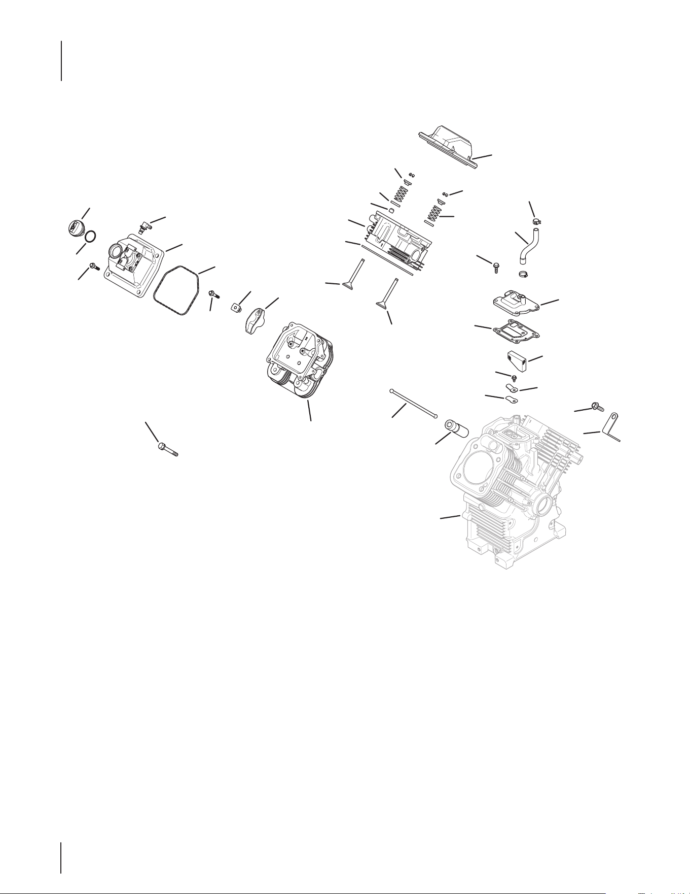
62
Kohler CH640-3123 Head/Valve/Breather
14
24
27
23
26
21
25
17
19
18
11
25
12
15
13
31
30
Crankcase
29
28
33
32
9
3
1
2
4
5
6
7
20
34
8
22
10
63
Kohler CH640-3123 Head/Valve/Breather
Ref.
Part Number Description
1 KH-24-153-32-S O-Ring
2 KH-24-227-02-S Oil Fill Cap Assembly
3 KH-M-651030-S Flange Screw, M6 x 1.0 x 30
4 KH-25-294-11-S 90 Degree Fitting Kit
5 KH-24-559-10-S Valve Cover-Fuel Pump Kit
6 KH-24-153-30-S Vlave Cover O-Ring
7 KH-M-640034-S Flange Screw, M6 x 1.0 x 34
8 KH-24-016-01 Exhaust Valve (Std)
— KH-24-016-02 Exhaust Valve (.25)
9 KH-24-841-02-S Cylinder Head Gasket Kit (C22-23)
10 KH-24-318-144-S #1 Cylinder Head Assembly Kit
11 KH-25-032-14-S Valve Stem Seal
12 KH-24-089-02 Valve Spring
13 KH-12-755-03 Retainer Kit
14 KH-24-755-141-S Valve Cover-Plain Kit
15 KH-25-173-28-S Valve Spring Cap
16 K H -235011-S Spring Retainer
17 KH-25-086-396-S Thread Forming Screw
18 KH-25-237-37-S Spring Hose Clamp
Ref.
Part Number Description
19 KH-24-326-89-S Breather Hose
20 KH-24-599-02-S Rocker Arm Pivot
21 KH-24-041-67-S Breather Gasket
22 KH-24-017-01 Intake Valve (Std)
— KH-24-017-02 Intake Valve (.25)
23 KH-M-0545010 Flange Screw, M5 x .8 X 10
24 KH-24-402-03 Breather Reed
25 KH-24-033-01 Breather Assembly Kit
26 KH -24 - 050 -11-S Breather Filter
27 KH-66-018-04-S Reed Retainer
28 KH-25-086-395-S Thread Forming Screw
29 KH-25-445-03-S Lift Strap
30 KH-25-351-11-S Hydraulic Valve Lifter
31 K H -24 - 411- 05 Push Rod
32 KH-62-086-08-S Flange Screw, M10 x 1.5 x 90
33 KH-24 -318-150-S #2 Cylinder Head Assembly Kit
34 KH-24-755-66 Valve Train Kit
— KH-25-186-01 Rocker Arm
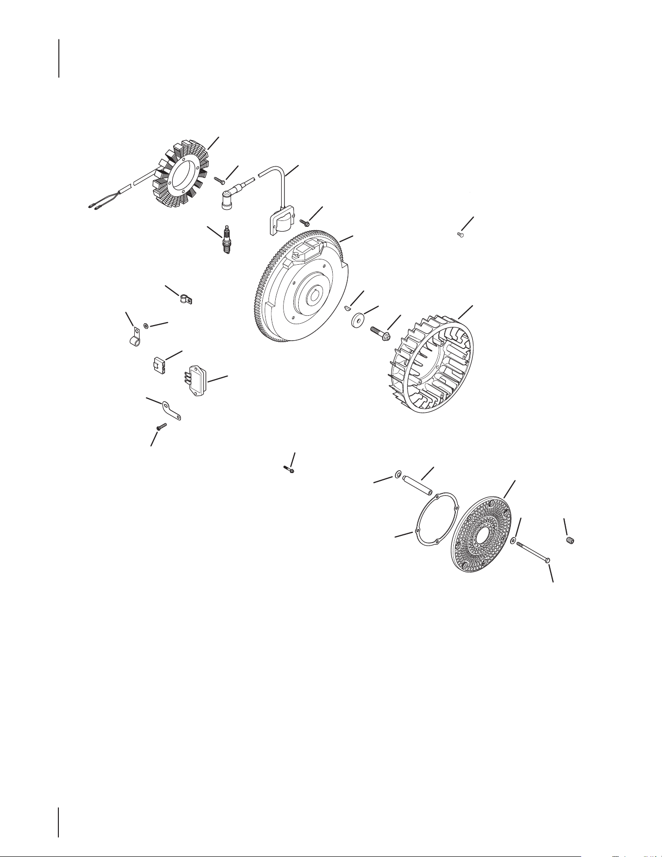
64
Kohler CH640-3123 Ignition/Electrical
1
5
24
4
3
2
6
7
8
9
26
25
16
14
15
10
12 13
11
17
18
20
22
21
23
19

65
Kohler CH640-3123 Ignition/Electrical
Ref.
Part Number Description
1 KH-237878 15/20 Amp Stator Kit
2 KH-25-086-402-S Thread Forming Screw
3 KH-24-584-45-S Module Ignition Key (CDI Fixed)
4 KH-25-086-399-S Thread Forming Screw
5 KH-24-025-55-S Flywheel
6 KH-X-42-15 Key, 3⁄16 x 5⁄8
7 KH-12- 468- 03 Flat Washer, 13⁄32
8 KH-25-086-361-S Flange Screw, M10 x 1.5 x 45
9 KH-24-157-11-S Fan
10 KH-24-162-39-S Grass Screen
11 KH-M-603100 Cap Screw, M6 x 1.0 x 99.5
12 KH-X-25-53 Flat Washer, 1⁄4 x 5⁄8
13 KH-25-086-43 Set Screw, #10-24 X 1⁄4
14 KH-24-141-06 Support Ring
15 KH-24-112-14 Spacer
16 K H -24 - 468 -11 Spring Washer, 10 MM
17 KH-25- 086 -157-S Hex Flange Hi-Lo Screw
18 KH-24-126-137-S Ground Strap Bracket
19 KH-41-403-10-S Regulator/Rectier
20 KH-25-155-41-S Connector
21 KH-235173 Cable Clip
22 KH-X-25-63 Flat Washer, 1⁄4 x 1⁄2
23 KH-210281-S Clip
24 KH-12-132-02-S Spark Plug (Std.)
25 KH-24- 086-17-S Flange Screw, M8 x 1.25 x 45
26 KH-25-086-91-S Washer Head Tap Screw, #8-18 x 1⁄2
NS KH-25-454-07-S Tie
NS KH-24-176-188-S Wiring Harness Assembly
NS 719-3096 Drive Shaft Adapter
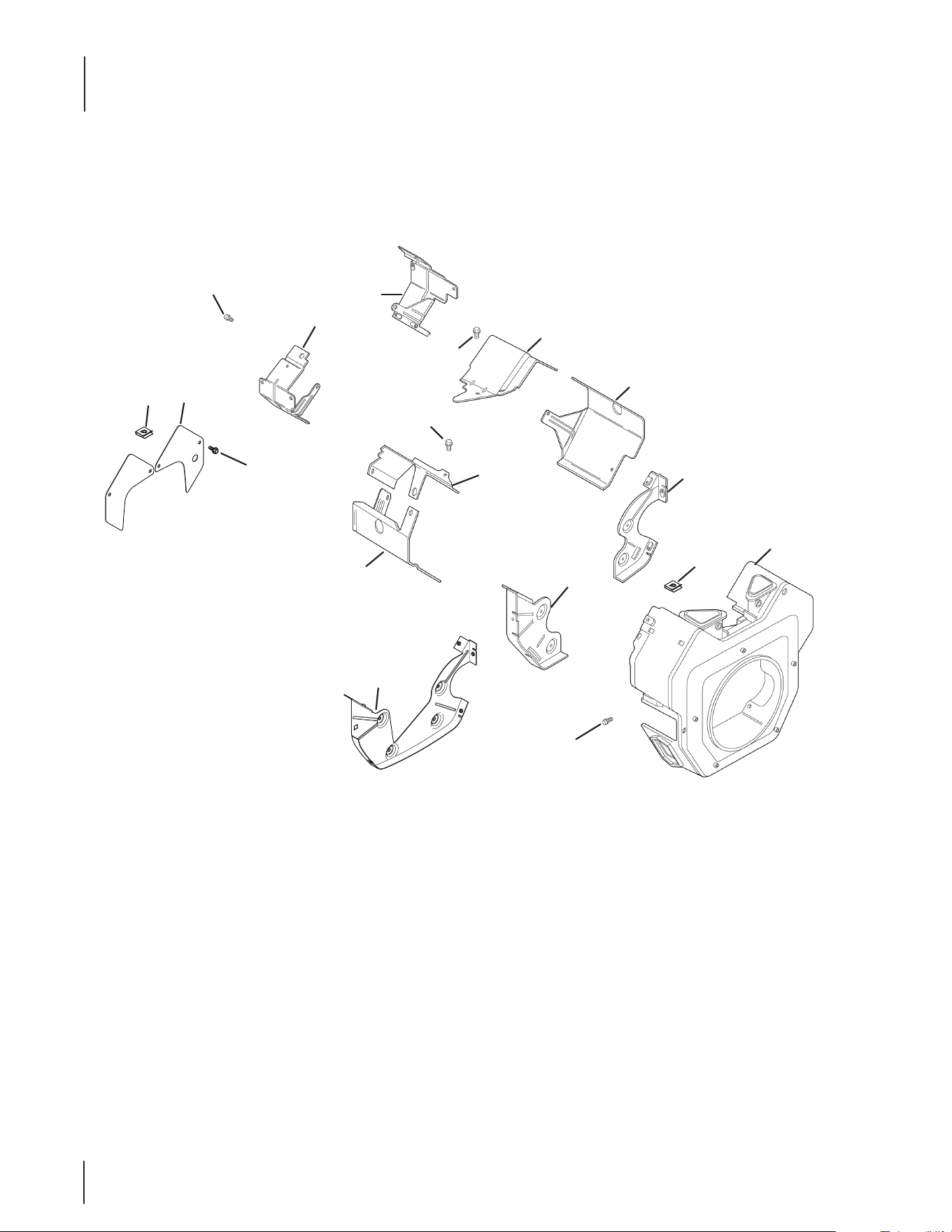
66
Kohler CH640-3123 Blower Housing & Baffles
2
1
3
4
10
7
6
5
8
13
10
12
11
10
9
7
14
12

67
Kohler CH640-3123 Blower Housing & Baffles
Ref.
Part Number Description
1 KH-M-639010-S Flange Screw, M6 x 1.0 x 10
2 KH-24-063-13-S Ducted Air-Oil Filter Bae
3 KH-24 -063-12-S Ducted Air-Starter Bae
4 KH-25-086-400-S Thread Forming Screw
5 KH-24-063-93-S Valley Bae, #1 Cylinder
6 KH-24-063-85-S Cylinder Bae Kit, #1 Side
7 KH-25-086-397-S Thread Forming Screw
8 KH-24-063-94-S Valley Bae, #2 Cylinder
9 KH-24-063-88-S Cylinder Bae Kit, #2 Side
10 KH-24-146 -59-S Backing Plate Kit
11 KH-24- 027-119-S Blower Housing Assembly Kit
12 KH-25-154-13-S Bae Mounting Clip
13 KH-25-086-398-S Thread Forming Screw
14 KH-25-755-20-S Access Panel Kit
NS KH-25-086-406-S Thread Forming Screw
NS KH-25-086-426-S Thread Forming Screw
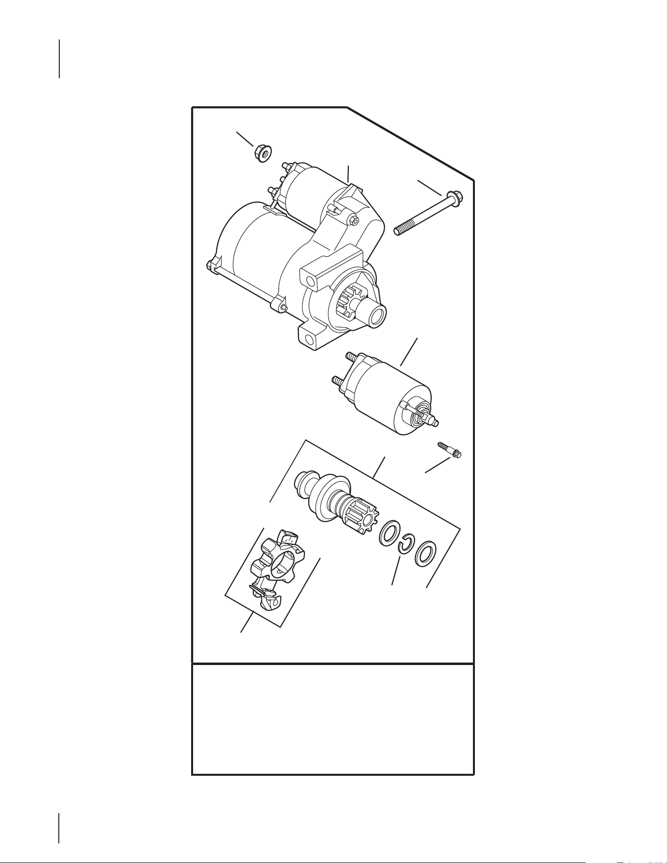
68
Kohler CH640-3123 Starting System
KH-25-098-08-S (Delco)
KH-25-098-09-S (Delco)
KH-25-098-11-S (Delco)
2
3
1
8
7
5
6
4

69
Kohler CH640-3123 Starting System
Ref.
Part Number Description
1 712-3086 Flange Nut, M8 x 1.25
2 KH -25 - 0 98 -11-S Electric Starter (Solenoid Shift)
3 KH-M-851080-S Flange Screw, M8 x 1.25 x 80
4 KH-25-435-06-S Solenoid Kit
5 KH-25-755-33-S Starter Pinion Kit
6 KH -25 - 0 86 -113-S External Torx Head Screw
7 KH-25-141-05-S Retaining Ring
8 KH-25-221-01-S Brush Holder Kit
* Service starter components according to the part number
printed on the starter. Starter components are NOT inter-
changeable. To replace complete Starter Assembly, order Part
Number 25 098 09-S.

70
Kohler CH640-3123 Engine Controls
4
3
6
5
7
10
9
8
2
1
24
25
26
27
12
11
7
16
15
2
1
13
17
19
18
20
21
22
23

71
Kohler CH640-3123 Engine Controls
Ref.
Part Number Description
1 KH-25-086-398-S Thread Forming Screw
2 KH-12-237-01 Cable Clamp
3 KH-25-086-473-S Thread Forming Screw
4 KH-41-468-03 Spring Washer, 1⁄4
5 KH-24-079-21-S Choke Linkage
6 KH-24-090-05 Choke Lever
7 KH-24-468-01 Flat Washer, 5.5 MM
8 KH-M-401030 Cap Screw, M4 x .7 x 30
9 KH-M-446030-S Nut, M4 x 0.7
10 KH-24-090-13 Throttle Control Lever
11 KH-M-541050-S Flange Nut, M5 x .8
12 KH-X-20-1 Spring Lock Washer, 1⁄4
13 KH-24-126-176-S Control Bracket
14 KH-24-089-03 Choke Return Spring
15 KH-M-547050-S Lock Nut, M5 x .8
16 KH-25-086-396-S Thread Forming Screw
17 KH-24-090-65-S Throttle Actuator Lever
18 KH-25-158-11 Throttle Linkage Bushing
19 KH-24-089-01 Linkage Spring
20 KH-25-158- 08 Linkage Retaining Bushing
21 KH-24-079-01 Throttle Linkage
22 KH-24-126-04-S Bracket
23 KH-24-089-51-S Throttle Limiter Spring
24 KH-24-211-03-S Bolt, M6 x 1.0 x 25
25 KH-24-090-69-S Governor Lever
26 KH-M-641060-S Flange Nut, M6 x 1.0
27 KH-24-089-48-S Governor Spring (Purple)
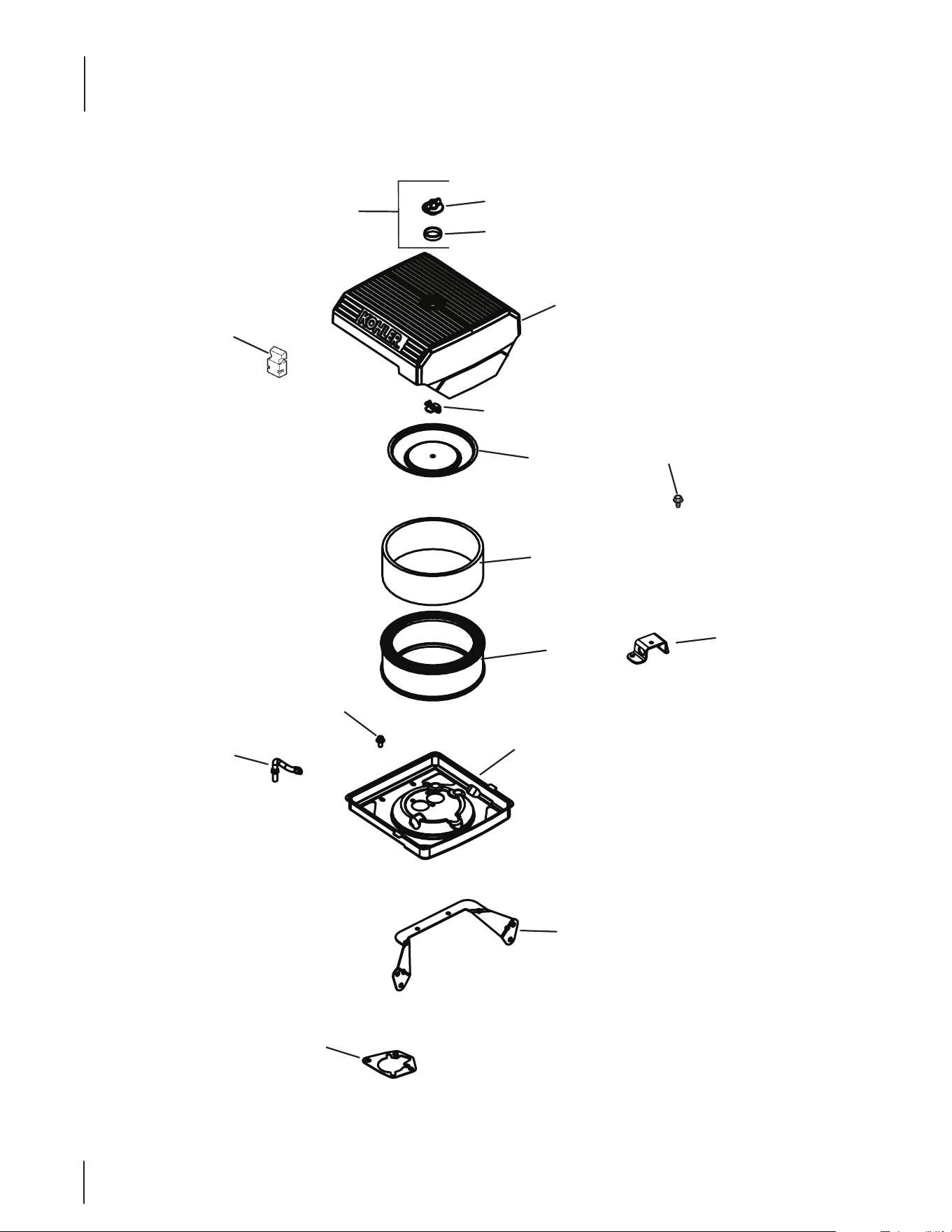
72
Kohler CH640-3123 Air Intake/Filtration
2
1
3
4
5
6
7
8
9
10
11
12
16
13
14
15
73
Kohler CH640-3123 Air Intake/Filtration
Ref.
Part Number Description
1 KH-25-341-04-S Cover Knob
2 KH-24-153-20-S O-Ring
3 KH-24- 096 -133-S A/C Cover
4 KH-24-032-03 Inner Air Cleaner Seal
5 KH-12-100-01 Wing Nut
6 KH-24-096-01 Inner Air Cleaner Cover
7 KH-47-883-03-S1 Pre-cleaner Element (Low)
8 KH-47-883-03-S1 Air Cleaner Element
9 KH-24-294-27-S Evaporative Hose Connector
10 KH-24-326-131-S Evap Hose
11 KH-24-126-130-S Air Cleaner Base Bracket
12 KH-24-041-06 Air Cleaner Base Gasket
13 KH-25-086-400-S Thread Forming Screw
14 KH-54-755-01-S Knob Kit w/ Seal
15 KH-24-126-206-S Air Cleaner Bracket
16 KH-24-094-84-S Air Cleaner Base Kit
NS KH-24-086-53-S Flange Thread Screw, M6 x 1.0 x 16
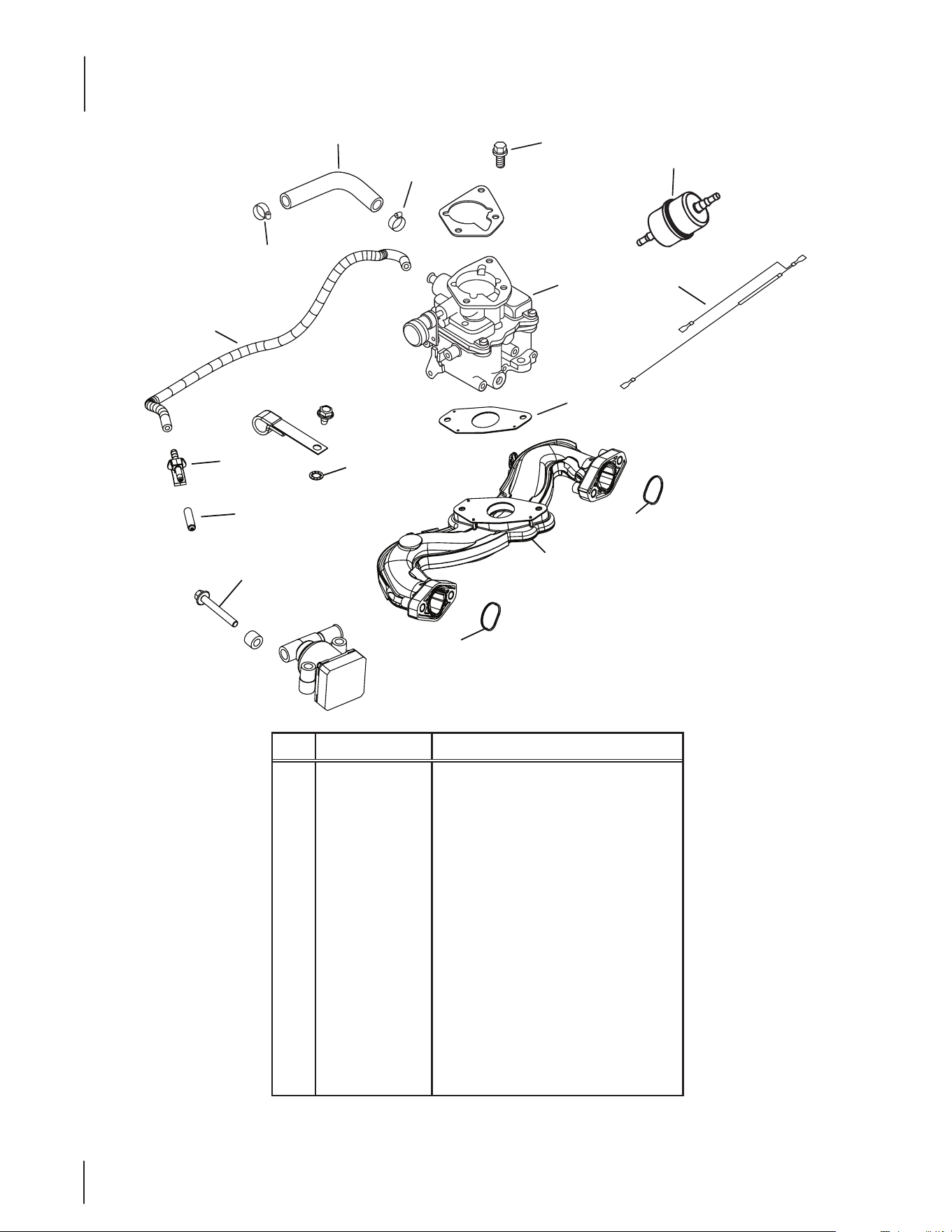
74
Kohler CH640-3123 Fuel System
Ref.
Part Number Description
1 KH -25 -111- 81-S Low Permeation Fuel Hose, 24"
2 KH-25-237-31-S Hose Clamp
3 KH-24-853-59-S Carburetor Kit w/ Gaskets
4 KH-25-086 -124 -S Flange Screw, M6 x 1.0 x 25
5 KH -X-22-11 Internal Tooth Lock Washer, 1/4
6 KH-24- 041-53-S Carburetor Gasket
7 KH-24- 050-13-S Fuel Filter
8 KH-24-518-24-S Ground Lead
9 KH-M-651040-S Flange Screw, M6 x 1.0 x 40
10 KH-25-155-51-S Evaporative Connector
11 KH-25-173-33-S Masking Cap
12 KH-25-326-08-S Evaporative Hose, 20”
13 KH-24-164-93-S Intake Manifold Kit
14 KH-24-153-27-S Intake Port O-Ring
1
2
2
3
4
6
7
13
14
14
12
10
11
8
5
9
75
Kohler CH640-3123 Miscellaneous
Kohler CH640-3123 Labels
Ref.
Part Number Description
1 KH-25-072-24-S Stud, M8 x 1.25 x 33
Ref.
Part Number Description
1 K H -2 5 -113 -70 -S Clear Laminate Decal
2 K H -24 -113- 4 0 0 -S Oil Sentry Decal
1
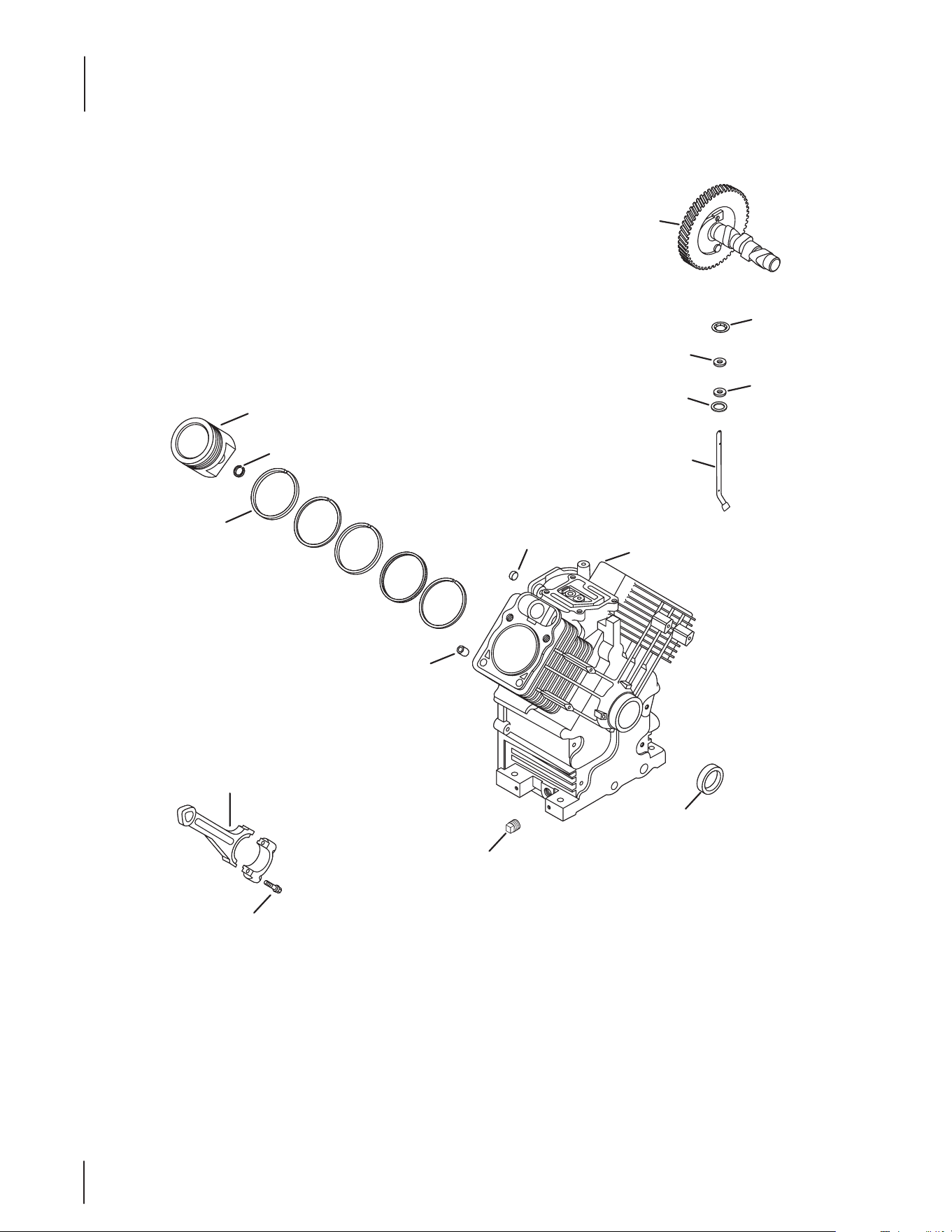
76
Kohler CH680-3106 Crankcase
1
14
3
5
4
2
Service with Short
Block or Mini-Block
9
10
6
8
12
11
13
7
15
77
Kohler CH680-3106 Crankcase
Ref.
Part Number Description
1 KH-24 -012-10-S Camshaft Kit
2 KH-M-931010-S Flat Washer, 9 MM
3 KH-28-032-09-S Governor Cross Shaft Seal
4 KH-24-468-15-S Flat Washer, 11⁄32
5 KH-24-144-38-S Governor Cross Shaft
6 KH-25-139-57-S Square Headd Pipe Plug, 3⁄8
7 KH-24- 032-19 -S Oil Seal (Helix Lip)
8 KH-24-067-34-S Connecting Rod Assembly
9 KH-24-380-16-S Locating Pin
10 KH-52-139-09-S Cup Plug
11 KH-24-018-01-S Piston Pin Retainer
12 KH-24-108-18-S Ring Set (Std)
— KH-24-108-19-S Ring Set (.08)
— KH-24-108-20-S Ring Set (.25)
— KH-24-108-21-S Ring Set (.50)
13 KH-24-874-54-S Piston Assembly Kit w/ Ring (Std.)
— KH-24-874-55-S Piston Assembly Kit w/ Ring Set (.08)
— KH-24-874-56-S Piston Assembly Kit w/Ring Set (.25)
— KH-24-874-57-S Piston Assembly Kit w/ Ring Set (.50)
14 KH-24-018-09-S Ring Retainer
15 KH-25-086-452-S Rod Bolts Kit

78
Kohler CH680-3106 Crankshaft
Ref.
Part Number Description
1 KH-24-014-347-S Crankshaft (Includes 2)
2 KH-52-139-09-S Cup Plug
1
2

79
Kohler CH680-3106 Oil Pan/Lubrication
Ref.
Part Number Description
1 KH-24-755-121-S Dipstick/Dipstick Tubes Kit
2 KH-24-038-10 -S Dipstick
3 KH-25-032-06-S Oil Seal
4 KH-25-139- 60-S Countersink Pipe Plug, 1/8
5 KH-25- 099-27-S Oil Pressure Switch
6 KH-25 -086-17-S Screw
— KH-24- 086-17-S Flange Screw, M8 x 1.25 x 45
7 KH-24-009-215-S Closure Plate Assembly
8 KH-12-144- 02 Governor Gear Shaft
9 KH-24-448-02-S Locking Tab
10 KH-24-043-12 Governor Gear Kit w/ Pin
11 KH-12-380 -01 Governor Regulating Pin
12 KH-24-153-08 O-Ring
13 KH-24-393-53-S Oil Pump Assembly Kit
14 KH-24-153-01 Oil Pick-Up O-Ring
Ref.
Part Number Description
15 KH-24-381-04 Oil Pick-Up
16 KH-X-25-53 Flat Washer, 1/4 x 5/8
17 KH-25-086-401-S Thread Forming Screw
18 KH-52-050-02-S Oil Filter
19 KH-24-136 -01 Oil Filter Nipple
20 KH-24-089-74-S Compression Spring
21 KH-24-153-33-S Oil Pump Cover Seal
22 KH-24 -381-13-S Oil Pick-Up Assembly
23 KH-24-153-34-S Oil Pick-Up O-Ring
24 KH-24-393-70-S Oil Pump Assembly
25 KH-24- 096 -151-S Oil Pump Cover
26 KH-25-086-414-S Button Head Screw
27 KH-25-194-03-S Pressure Relief Ball
28 KH-24-123-25-S Dipstick Tube
3
4
6
5
10
9
11
8
12
13
14
15
16
17
19
7
2
18
1
28
20
24
25
26
27
22
23
21
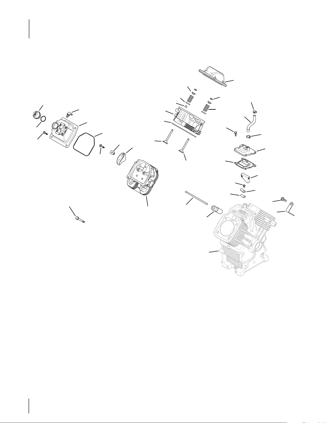
80
Kohler CH680-3106 Head/Valve/Breather
14
24
27
23
26
21
25
17
20
19
18
11
25
12
15
13
31
30
Crankcase
29
28
33
32
9
3
1
2
4
5
6
7
35
34
8
22
10

81
Kohler CH680-3106 Head/Valve/Breather
Ref.
Part Number Description
1 KH-24-153-32-S O-Ring
2 KH-24-227-02-S Oil Fill Cap Assembly
3 KH-M-651030-S Flange Screw, M6 x 1.0 x 30
4 KH-25-294-11-S 90 Degree Fitting Kit
5 KH-24-559-10-S Valve Cover-Fuel Pump Kit
6 KH-24-153-30-S Vlave Cover O-Ring
7 KH-M-640034-S Flange Screw, M6 x 1.0 x 34
8 KH-24-016-01 Exhaust Valve (Std)
— KH-24-016-02 Exhaust Valve (.25)
9 KH-24-841-02-S Cylinder Head Gasket Kit (C17-22)
10 KH-24-318-144-S #1 Cylinder Head Assembly Kit
11 KH-25-032-14-S Valve Stem Seal
12 KH-24-089-02 Valve Spring
13 KH-12-755-03 Retainer Kit
14 KH-24-755-141-S Valve Cover-Plain Kit
15 KH-25-173-28-S Valve Spring Cap
16 K H -235011-S Spring Retainer
17 KH-25-086-396-S Thread Forming Screw
18 KH-25-237-37-S Spring Hose Clamp
19 KH-24-326-89-S Breather Hose
Ref.
Part Number Description
20 KH-25-237-31-S Hose Clamp (KM)
21 KH-24-041-67-S Breather Gasket
22 KH-24-017-01 Intake Valve (Std)
— KH-24-017-02 Intake Valve (.25)
23 KH-M-0545010 Flange Screw, M5 x .8 x 10
24 KH-24-402-03 Breather Reed
25 KH-24-033-01 Breather Assembly Kit
26 KH -24 - 050 -11-S Breather Filter
27 KH-66-018-04-S Reed Retainer
28 KH-25-086-395-S Thread Forming Screw
29 KH-25-445-03-S Lift Strap
30 KH-25-351-11-S Hydraulic Valve Lifter
31 K H -24 - 411- 05 Push Rod
32 KH-62-086-08-S Flange Screw, M10 x 1.5 x 90
33 KH-24 -318-150-S #2 Cylinder Head Assembly Kit
34 KH-24-755-66 Valve Train Kit
— KH-25-186-01 Rocker Arm
35 KH-24-599-02-S Rocker Arm Pivot
NS KH-24-755-147-S Cylinder Head Hardware Kit
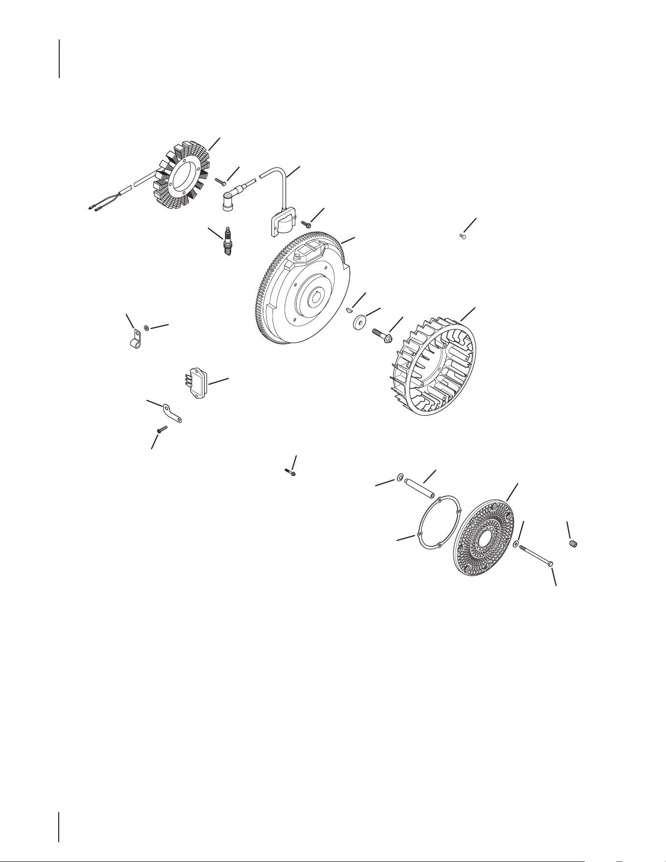
82
Kohler CH680-3106 Ignition/Electrical
1
5
24
4
3
2
6
7
8
9
23
20
16
14
15
10
12 13
11
17
18
22
21
19

83
Kohler CH680-3106 Ignition/Electrical
Ref.
Part Number Description
1 KH-237878 15/20 Amp Stator Kit
2 KH-25-086-402-S Thread Forming Screw
3 KH-24-584-45-S Module Ignition Key (CDI Fixed)
4 KH-25-086-473-S Thread Forming Screw
5 KH-24-025-55-S Flywheel
6 KH-X-42-15 Key, 3⁄16 x 5⁄8
7 KH-12- 468- 03 Flat Washer, 13⁄32
8 KH-25-086-361-S Flange Screw, M10 x 1.5 x 45
9 KH-24-157-11-S Fan
10 KH-24-162-39-S Grass Screen
11 KH-M-603100 Cap Screw, M6 x 1.0 x 99.5
12 KH-X-25-53 Flat Washer, 1⁄4 x 5⁄8
13 KH-25-086-43 Set Screw, #10-24 X 1⁄4
14 KH-24-141-06 Support Ring
15 KH-24-112-14 Spacer
16 K H -24 - 468 -11 Spring Washer, 10 MM
17 KH-25- 086 -157-S Hex Flange Hi-Lo Screw
18 KH-24-126-137-S Ground Strap Bracket
19 KH-41-403-10-S Regulator/Rectier
20 KH-24- 086 -17-S Flange Screw, M8 x 1.25 x 45
21 KH-235173 Cable Clip
22 KH-X-25-63 Flat Washer, 1⁄4 x 1⁄2
23 KH-25-086-91-S Washer Head Tap Screw, #8-18 x 1⁄2
24 KH-12-132-02-S Spark Plug (Std.)
NS KH-25-454-07-S Tie
NS KH-24-176-188-S Wiring Harness Assembly
NS 719-3096 Drive Shaft Adapter
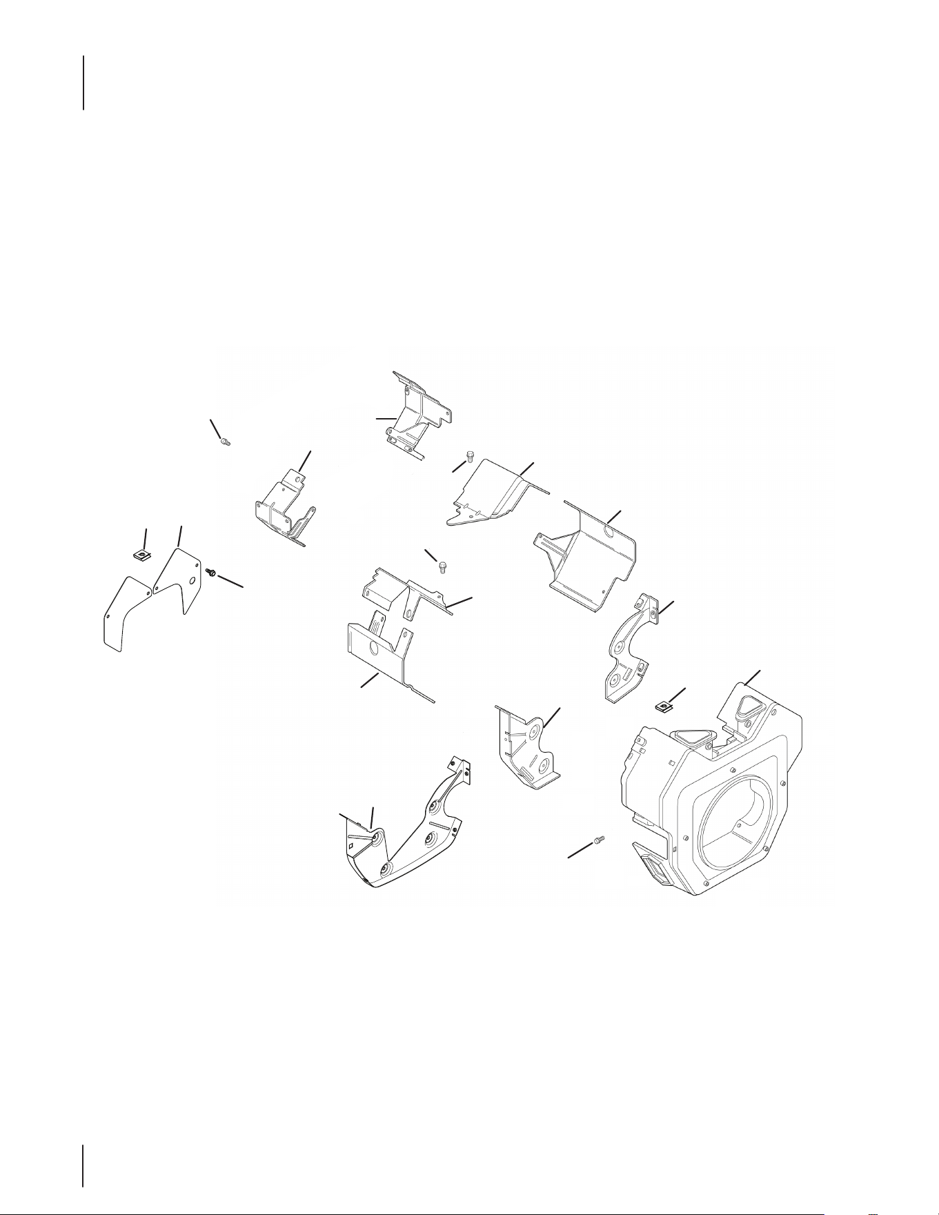
84
Kohler CH680-3106 Blower Housing & Baffles
2
1
3
4
10
7
6
5
8
13
10
12
11
10
9
7
14
12

85
Kohler CH680-3106 Blower Housing & Baffles
Ref.
Part Number Description
1 N/A Flange Screw, M6 x 1.0 x 10
2 KH-24-063-13-S Ducted Air-Oil Filter Bae
3 KH-24 -063-12-S Ducted Air-Starter Bae
4 KH-25-086-400-S Thread Forming Screw
5 KH-24-063-93-S Valley Bae, #1 Cylinder
6 KH-24-063-85-S Cylinder Bae Kit, #1 Side
7 KH-25-086-397-S Thread Forming Screw
8 KH-24-063-94-S Valley Bae, #2 Cylinder
9 KH-24-063-88-S Cylinder Bae Kit, #2 Side
10 KH-24-146 -59-S Backing Plate Kit
11 KH-24- 027-119-S Blower Housing Assembly Kit
12 KH-25-154-13-S Bae Mounting Clip
13 KH-25-086-398-S Thread Forming Screw
14 KH-25-755-20-S Access Panel Kit
NS KH-25-086-406-S Thread Forming Screw
NS KH-25-086-426-S Thread Forming Screw

86
Kohler CH680-3106 Starting System
KH-25-098-11-S (Delco)
KH-25-098-11-S (Delco)
KH-25-098-11-S (Delco)
2
3
1
8
7
5
6
4

87
Kohler CH680-3106 Starting System
Ref.
Part Number Description
1 712-3086 Flange Nut, M8 x 1.25
2 KH -25 - 0 98 -11-S Electric Starter (Solenoid Shift)
3 KH-M-851080-S Flange Screw, M8 x 1.25 x 80
4 KH-25-435-06-S Solenoid Kit
5 KH-25-755-33-S Starter Pinion Kit
6 KH -25 - 0 86 -113-S External Torx Head Screw
7 KH-25-141-05-S Retaining Ring
8 KH-25-221-01-S Brush Holder Kit
* Service starter components according to the part number
printed on the starter. Starter components are NOT inter-
changeable. To replace complete Starter Assembly, order Part
Number 25 098 09-S.

88
Kohler CH680-3106 Engine Controls
4
3
6
5
7
10
9
8
2
1
24
25
26
27
12
11
7
16
15
2
1
13
17
19
18
20
21
22
23
89
Kohler CH680-3106 Engine Controls
Ref.
Part Number Description
1 KH-25-086-398-S Thread Forming Screw
2 KH-12-237-01 Cable Clamp
3 KH-25-086-473-S Thread Forming Screw
4 KH-41-468-03 Spring Washer, 1⁄4
5 KH-24-079-21-S Choke Linkage
6 KH-24-090-05 Choke Lever
7 KH-24-468-01 Flat Washer, 5.5 MM
8 KH-M-401030 Cap Screw, M4 x .7 x 30
9 KH-M-446030-S Nut, M4 x 0.7
10 KH-24-090-13 Throttle Control Lever
11 KH-M-541050-S Flange Nut, M5 x .8
12 KH-X-20-1 Spring Lock Washer, 1⁄4
13 KH-24-126-176-S Control Bracket
14 KH-24-089-03 Choke Return Spring
15 KH-M-547050-S Lock Nut, M5 x .8
16 KH-25-086-396-S Thread Forming Screw
17 KH-24-090-65-S Throttle Actuator Lever
18 KH-25-158-11 Throttle Linkage Bushing
19 KH-24-089-01 Linkage Spring
20 KH-25-158- 08 Linkage Retaining Bushing
21 KH-24-079-01 Throttle Linkage
22 KH-24-126-04-S Bracket
23 KH-24-089-51-S Throttle Limiter Spring
24 KH-24-211-03-S Bolt, M6 x 1.0 x 25
25 KH-24-090-69-S Governor Lever
26 KH-M-641060-S Flange Nut, M6 x 1.0
27 KH-24-089-48-S Governor Spring (Purple)

90
Kohler CH680-3106 Air Intake/Filtration
2
1
3
4
5
6
7
8
9
10
11
12
16
13
14
15

91
Kohler CH680-3106 Air Intake/Filtration
Ref.
Part Number Description
1 KH-25-341-04-S Cover Knob
2 KH-24-153-20-S O-Ring
3 KH-24- 096 -133-S A/C Cover
4 KH-24-032-03 Inner Air Cleaner Seal
5 KH-12-100-01 Wing Nut
6 KH-24-096-01 Inner Air Cleaner Cover
7 KH-47-883-03-S1 Pre-cleaner Element (Low)
8 KH-47-883-03-S1 Air Cleaner Element
9 KH-24-294-27-S Evaporative Hose Connector
10 KH-24-326-131-S Evap Hose
11 KH-24-126-130-S Air Cleaner Base Bracket
12 KH-24-041-06 Air Cleaner Base Gasket
13 KH-25-086-400-S Thread Forming Screw
14 KH-54-755-01-S Knob Kit w/ Seal
15 KH-24-126-206-S Air Cleaner Bracket
16 KH-24-094-84-S Air Cleaner Base Kit
NS KH-24-086-53-S Flange Thread Screw, M6 x 1.0 x 16
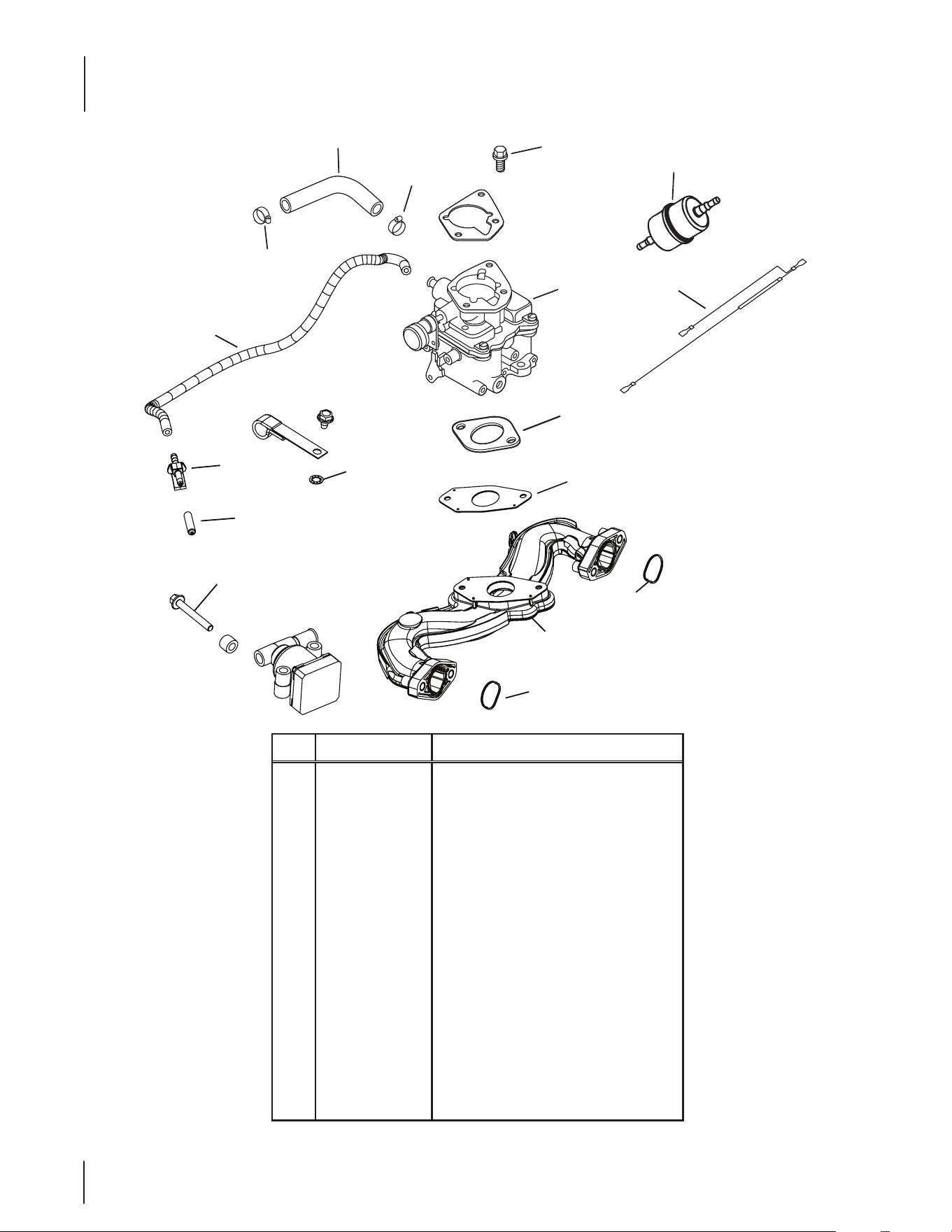
92
Kohler CH680-3106 Fuel System
Ref.
Part Number Description
1 KH -25 -111- 81-S Low Permeation Fuel Hose, 24"
2 KH-25-237-31-S Hose Clamp
3 KH-24-853-59-S Carburetor Kit w/ Gaskets
4 KH-25-086 -124 -S Flange Screw, M6 x 1.0 x 25
5 KH -X-22-11 Internal Tooth Lock Washer, 1/4
6 KH-24- 041-53-S Carburetor Gasket
7 KH-24- 050-13-S Fuel Filter
8 KH-24-518-24-S Ground Lead
9 KH-M-651040-S Flange Screw, M6 x 1.0 x 40
10 KH-25-155-51-S Evaporative Connector
11 KH-25-173-33-S Masking Cap
12 KH-25-326-08-S Evaporative Hose, 20”
13 KH-24-164-93-S Intake Manifold Kit
14 KH-24-153-27-S Intake Port O-Ring
15 KH-24- 041-17 Carburetor Gasket
1
2
2
3
4
6
7
13
14
14
12
10
11
8
5
9
15
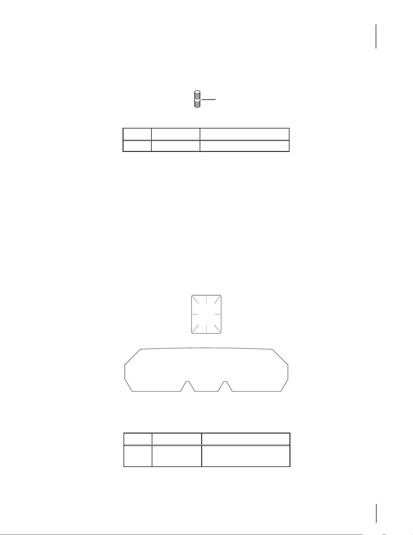
93
Kohler CH680-3106 Miscellaneous
Kohler CH680-3106 Labels
Ref.
Part Number Description
1 KH-25-072-24-S Stud, M8 x 1.25 x 33
Ref.
Part Number Description
1 K H -2 5 -113 -70 -S Clear Laminate Decal
2 K H -24 -113- 411-S Oil Sentry Decal
1

No tes
94

95Notes

CUB CADET LLC, P.O. BOX 361131 CLEVELAND, OHIO 44136-0019
G
E
N
U
I
N
E
F
A
C
T
O
R
Y
P
A
R
T
S
To order replacement parts, call a Customer Support Representative at (800) 965-4CUB.
Locate your nearest Cub Cadet dealer at (877) 282-8684
or visit www.cubcadet.com to find the nearest Cub Cadet dealer in your area.