CUB CADET LLC, P.O. BOX 361131 CLEVELAND, OHIO 44136-0019
Printed In USA
Op e r a t O r ’s Ma n u a l
Set-Up • Maintenance • Service • Warranty
WARNING
READ AND FOLLOW ALL SAFETY RULES AND INSTRUCTIONS IN THIS MANUAL
BEFORE ATTEMPTING TO OPERATE THIS MACHINE.
FAILURE TO COMPLY WITH THESE INSTRUCTIONS MAY RESULT IN PERSONAL INJURY.
Series 2000 42-, 48-, 50- and 54-inch Deck Attachments
Model 19A40016100 shown
Form No. 769-06621A
(February 2, 2011)

Customer Support
If you have difficulty assembling this product or have any questions regarding the controls, operation, or maintenance of
this machine, you can seek help from the experts. Choose from the options below:
Visit us on the web at www.cubcadet.com◊
Locate your nearest Cub Cadet Dealer at (877) 282-8684◊
Write us at Cub Cadet LLC • P.O. Box 361131 • Cleveland, OH • 44136-0019◊
Thank you for purchasing a a Cub Cadet Series 2000 Deck
Attachment. It was carefully engineered to provide excellent
performance when properly operated and maintained.
Please read this entire manual prior to operating the equipment.
It instructs you how to safely and easily set up, operate and
maintain your machine. Please be sure that you, and any other
persons who will operate the machine, carefully follow the
recommended safety practices at all times. Failure to do so could
result in personal injury or property damage.
All information in this manual is relative to the most recent
product information available at the time of printing. Review
this manual frequently to familiarize yourself with the machine,
its features and operation. Please be aware that this Operator’s
Manual may cover a range of product specifications for various
models. Characteristics and features discussed and/or illustrated
in this manual may not be applicable to all models. Cub Cadet
LLC reserves the right to change product specifications, designs
and equipment without notice and without incurring obligation.
If you have any problems or questions concerning the machine,
phone your local Cub Cadet dealer or contact us directly. Cub
Cadet’s Customer Support telephone numbers, web site address
and mailing address can be found on this page. We want to
ensure your complete satisfaction at all times.
Throughout this manual, all references to right and left side of the
machine are observed from the operating position.
Thank You
Record Product Information
Before setting up and operating your new equipment, please
locate the model plate on the equipment and record the
information in the provided area to the right. You can locate
the model plate on the rear surface of the cutting deck. This
information will be necessary, should you seek technical support
via our web site or with your local Cub Cadet dealer.
MO d e l nu M b e r
se r i a l nu M b e r
To The Owner
1
2
Assembly & Set-Up .................................................. 3
Maintenance ............................................................ 6
Service ...................................................................... 7
Warranty Information ............................Back Cover
Table of Contents
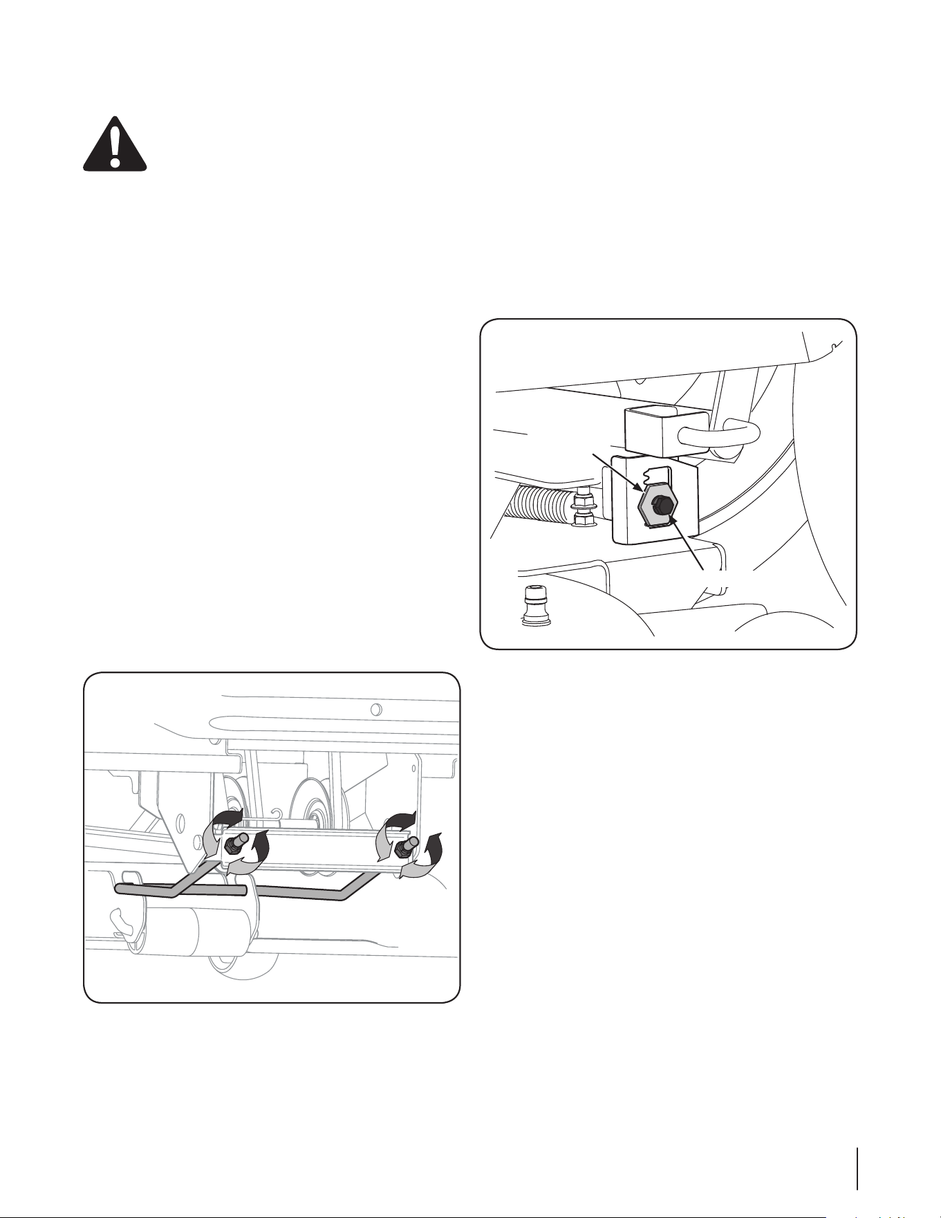
Locate the deck support pin found on the left bracket and 5.
pull it outward. Align it with the hole in the lift link before
releasing it to secure the pin in place. Repeat on the right
side of the deck. See Fig. 2-2.
Remove and retain the lock nuts from each end of the front 6.
hanger. Position the hanger over the hooks found on the
front of cutting deck, with the angled ends facing upward.
Insert the ends of the front hanger through the holes in 7.
the front hanger bracket and secure with the two lock nuts
removed earlier. See Fig. 2-3.
NOTE: Do not fully tighten the lock nuts at this point.
Mounting the Deck
This manual covers all cutting deck attachments (19A40012100
19A40013100, 19A40014100, 19A40015100 & 19A40016100) for
Cub Cadet Series 2000 Garden Tractors. Although they vary in
size and appearance, each cutting deck mounts to the tractor in
the same fashion.
WARNING! Turn the tractor’s engine is off, set the
parking brake and remove the ignition key before
mounting the cutting deck.
Attaching the Deck
Place the deck lift lever in the notch for highest cutting 1.
position to raise the deck lift links up and out of the way.
NOTE: On models with electric lift, place the cutting height
lever in the L position and use the deck lift switch to raise
the deck lift links up and out of the way.
From the right side, carefully slide the cutting deck under 2.
the tractor.
NOTE: Carefully positioning a piece of 2x4 under the
center, rear of the cutting deck to raise it up slightly will aid
in completing the following steps.
Align the tractor’s lift links with deck support pins found 3.
on the rear deck brackets. See Fig. 2-1.
Place the deck lift lever in the notch for lowest cutting 4.
position to lower the deck lift links.
NOTE: On models with electric lift, use the deck lift switch
to lower the deck lift links.
a
b
c
Figure 2-2
Figure 2-1
Contents of Crate
One Cutting Deck Assembly• One Front Hanger w/ Lock Nuts• One PTO Belt•
One Operator’s Manual• One or Two Upstop Brackets *• Two or Four Hex Washer Screws *•
Figure 2-3
Assembly & Set-Up
2
3
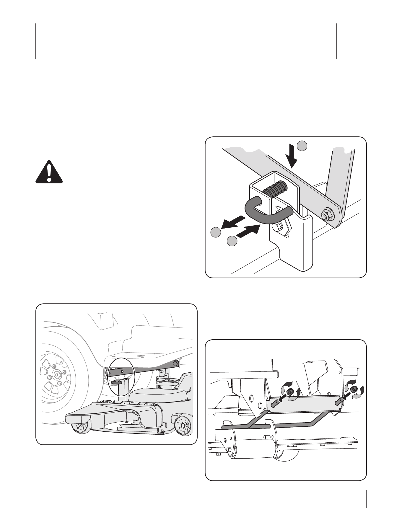
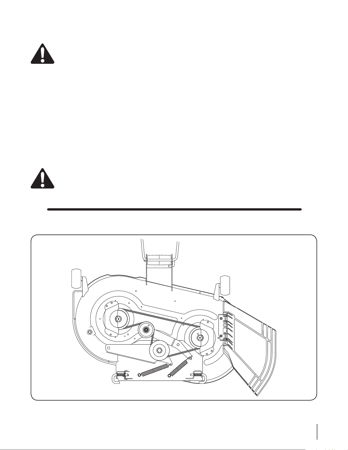
Routing the PTO Belt
Working from the front of the tractor, route the belt around 1.
the PTO clutch pulley, with the ‘V’ side of the belt seated in
the pulley. Carefully feed the belt downward and route it in
the two mule drive pulleys. See Fig. 2-4.
NOTE: The small belt keeper found on the right-hand mule
drive pulley does not have to be removed in order to route
the belt. Simply bend the keeper outward slightly and slip
the belt past it and onto the pulley.
Feed the belt rearward, toward the deck drive pulley found 2.
on the cutting deck.
Working on the left side of the tractor, insert a ¹/3. 2-inch drive
ratchet wrench, set to loosen, into square hole found on the
idler bracket.
Pivot the wrench rearward to move the deck drive pulley 4.
forward. See Fig. 2-5
WARNING! Avoid pinching injuries. Never place
your fingers on the idler spring or between the belt
and a pulley while installing the belt.
Carefully route the PTO belt around the deck drive pulley, 5.
with the ‘V’ side of the belt facing inward, by slowly
rotating the pulley with the belt in your palm. Once the
belt is seated, slowly allow the wrench to pivot forward,
applying tension. See Fig. 2-6.
NOTE: If there appears to be little or no tension on the PTO
belt, check to make sure the belt didn’t slip off one of the
mule drive pulleys while completing steps 2-5.
Installing the Upstop Brackets
The upstop brackets need to be installed on the frame of the
tractor before making any adjustments. There are a left and right
hand bracket on all deck attachments except 19A40012100 .This
attachment has only one upstop bracket that is installed on the
left side of the frame. The brackets and hex screws are shipped in
the manual bag.
Attach the upstop bracket on the left side using the hex 1.
washer screws as shown in Fig. 2-7.
Repeat the procedure on the right side for all attachments 2.
except 19A40012100.
Mule Drive
Pulleys
PTO Clutch
Figure 2-4
Figure 2-5
Figure 2-6
Upstop Bracket
Hex Washer Screws
Figure 2-7
4 se c t i O n 2 — as s e M b l y & se t -up
Adjusting the Deck
WARNING! Shut the engine off, remove the
ignition key and engage the parking brake before
making adjustments. Protect your hands by using
heavy gloves when handling the blades.
NOTE: Check the tractor’s tire pressure before performing
any deck leveling adjustments. Refer to Tires in your tractor’s
Operator’s Manual for information regarding tire pressure.
Leveling the Deck (Front To Rear)
The front of the cutting deck is supported by a hanger that can
be adjusted to level the deck from front to rear. The front of the
deck should be between 1⁄4” and 3⁄8” lower than the rear of the
deck. Adjust as follows:
Park the tractor parked on a firm, level surface and place 1.
the deck lift lever in a middle position.
NOTE: On models with electric lift, place the cutting height
lever in a middle position and use the deck lift switch to
lower the deck to that position.
Rotate the blade nearest the discharge chute so that it is 2.
parallel with the tractor.
Measure the distance from the front of the blade tip to the 3.
ground and the rear of the blade tip to the ground. The
first measurement taken should be between 1⁄4” and 3⁄8” less
than the second measurement.
NOTE: Determine the approximate distance necessary for
proper adjustment and proceed, if necessary.
To 4. raise the front of the deck, tighten (thread inward) the
hex nut against the front hanger bracket.
To 5. lower the front of the deck, loosen (thread outward) the
hex nuts, away from the front hanger bracket. See Fig. 2-8.
Retighten the hex nuts when proper adjustment is achieved.6.
Leveling the Deck (Side to Side)
If the cutting deck appears to be mowing unevenly, a side to side
adjustment can be performed. Adjust if necessary as follows:
With the tractor parked on a firm, level surface, place the 1.
deck lift lever in the middle position and rotate both blades
so that they are perpendicular with the tractor.
Measure the distance from the outside of the left blade 2.
tip to the ground and the distance from the outside of the
right blade tip to the ground. Both measurements taken
should be equal. If they’re not, proceed to the next step.
Loosen, but do NOT remove, the hex bolt on the left deck 3.
hanger bracket. See Fig. 2-9.
Using a wrench, raise or lower the left side of the deck by 4.
turning the adjustment gear. See Fig. 2-9.
The deck is properly leveled when both blade tip 5.
measurements taken earlier are equal. Retighten the
hex bolt on the left deck hanger bracket when proper
adjustment is achieved.
Figure 2-8
Hex Bolt
Adjustment
Gear
Figure 2-9
5se c t i O n 2 — as s e M b l y & se t -up
Maintenance
WARNING! Before performing any maintenance or
repairs, disengage PTO, set parking brake, stop
engine and remove key to prevent unintended
starting.
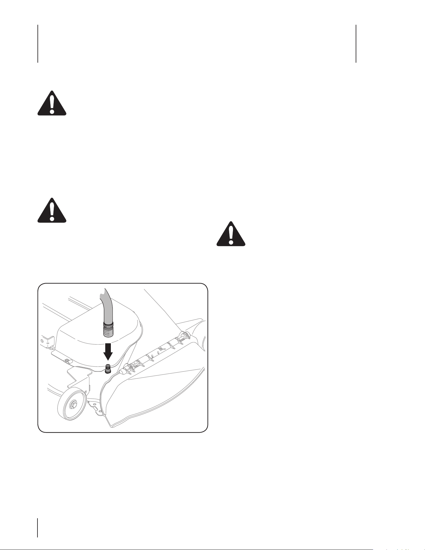
Smart Jet
Your tractor’s deck is equipped with a water port on its surface as
part of its deck wash system.
Use the Smart Jet to rinse grass clippings from the deck’s
underside and prevent the buildup of corrosive chemicals.
Complete the following steps AFTER EACH MOWING:
Drive the tractor to a level, clear spot on your lawn, near 1.
enough for your garden hose to reach.
CAUTION: Make certain the tractor’s discharge
chute is directed AWAY from your house, garage,
parked cars, etc.
Disengage the PTO (Blade Engage), set the parking brake 1.
and stop the engine.
Thread the hose coupler (packaged with your tractor’s 2.
Operator’s Manual) onto the end of your garden hose.
Attach the hose coupler to the water port on your decks 3.
surface. See Fig. 3-1.
Turn the water on.4.
While sitting in the operator’s position on the tractor, start 5.
the engine and place the throttle lever in the FAST (rabbit)
position.
Move the tractor’s PTO (Blade Engage) into the ON position.6.
Remain in the operator’s position with the cutting deck 7.
engaged for a minimum of two minutes, allowing the
underside of the cutting deck to thoroughly rinse.
Move the tractor’s PTO (Blade Engage) into the OFF 8.
position.
Turn the ignition key to the STOP position to turn the 9.
tractor’s engine off.
Turn the water off and detach the hose coupler from the 10.
water port on your deck’s surface.
On models with two water ports, repeat steps 4 through 11 11.
on the opposite side of the cutting deck.
After cleaning your deck with the Smart Jet system, return to the
operator’s position and engage the PTO. Keep the cutting deck
running for a minimum of two minutes, allowing the underside
of the cutting deck to thoroughly dry.
Lubrication
WARNING! Before lubricating, repairing, or
inspecting, always disengage PTO, set parking
brake, stop engine and remove key to prevent
unintended starting.
Deck Wheels
Each of the tractor deck’s gauge wheels is equipped with a
grease fitting. Lubricate with a No. 2 multi-purpose grease
applied with a grease gun after every 25 hours of tractor
operation
Deck Spindles
Grease fittings can be found on each deck spindle. Lubricate
with 251H EP grease or an equivalent No. 2 multi-purpose lithium
grease. Using a grease gun, apply two strokes (minimum) or
sufficient grease to the spindle shaft after every 25 hours of
tractor operation
NOTE: On some deck models it is necessary to remove the belt
covers in order to access the deck spindle grease fittings.
Figure 3-1
Maintenance
3
6
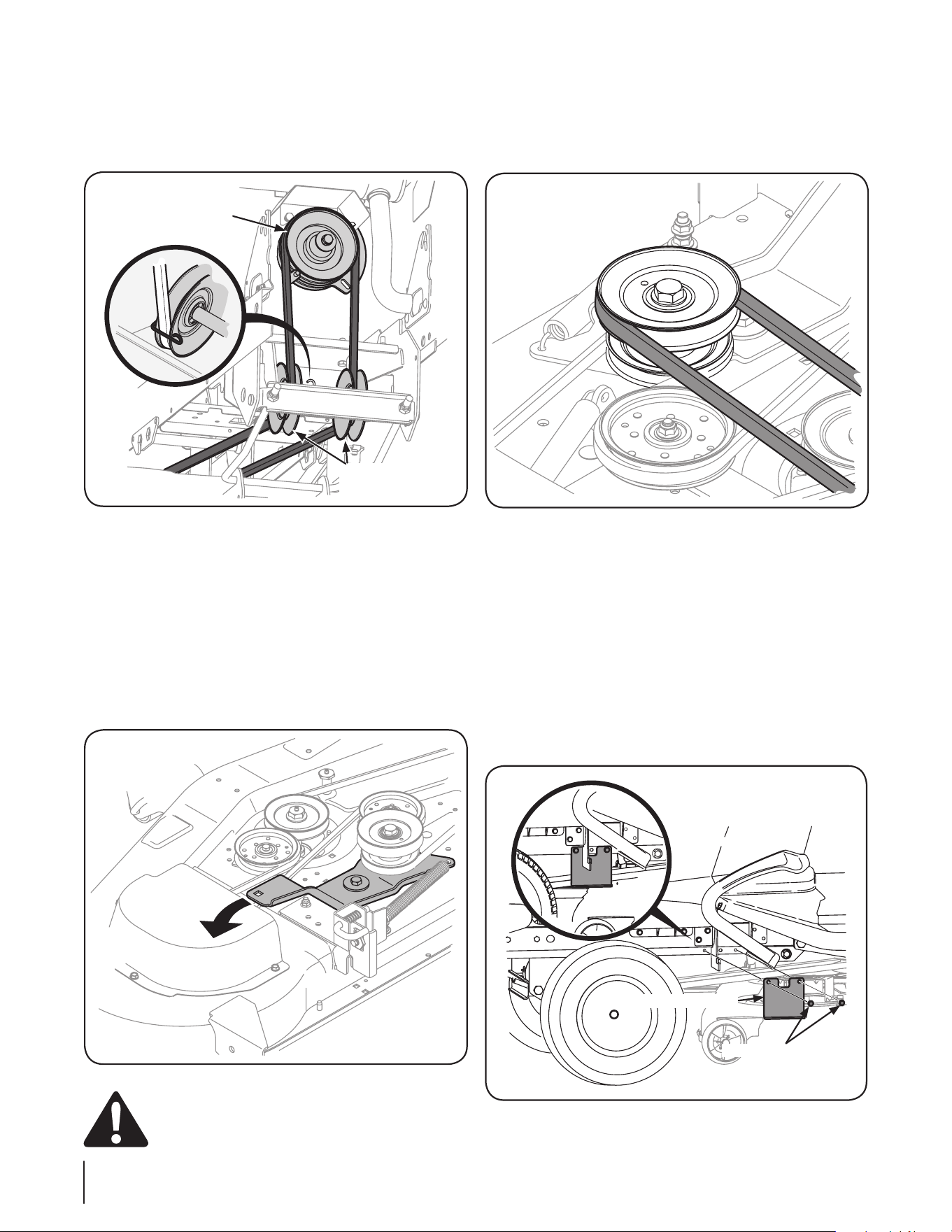
Cutting Deck Removal
To remove the cutting deck, proceed as follows:
Place the PTO/Blade Engage switch in the disengaged 1.
(OFF) position and engage the parking brake.
NOTE: Carefully positioning a piece of 2x4 under the
center, rear of the cutting deck to raise it up slightly will aid
in completing the following steps.
Lower the deck by moving the deck lift lever into the 2.
bottom notch on the right fender.
NOTE: On models with electric lift, place the cutting height
lever in the L position and use the deck lift switch to lower
the deck lift links.
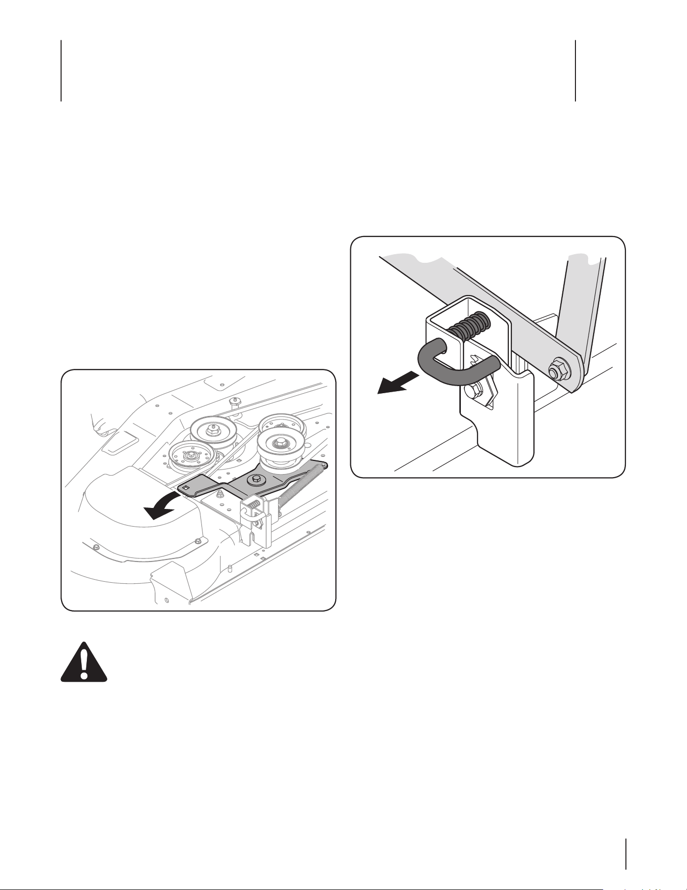
Working on the left side of the tractor, insert a ¹/3. 2-inch drive
ratchet wrench, set to loosen, into square hole found on the
idler bracket.
Pivot the wrench rearward to move the deck drive pulley 4.
forward. See Fig. 4-1
WARNING! Avoid pinching injuries. Never place
your fingers on the idler spring or between the belt
and a pulley while installing the belt.
Carefully remove the PTO belt around the deck drive pulley, 5.
Feed the belt forward and remove it from around the mule 6.
drive pulleys and the tractor’s PTO clutch pulley.
Looking at the cutting deck from the left side of the tractor, 7.
locate the deck support pin on the rear left side of the
deck.
Pull the deck support pin outward to release the deck from 8.
the deck lift arm. See Fig. 4-2.
Repeat the above steps on the tractor’s right side.9.
Move the deck lift lever into the top notch to raise the deck 10.
lift links up and out of the way.
NOTE: On models with electric lift, place the cutting height
lever in the L position and use the deck lift switch to raise
the deck lift links up and out of the way.
Gently slide the cutting deck toward the front of the 11.
tractor, carefully guiding the hooks on the deck off of the
front hanger.
Gently slide the cutting deck (from the right side) out from 12.
underneath the tractor.
Figure 4-2
Figure 4-1
Service
4
7
Cutting Blades
WARNING! Shut the engine off and remove
ignition key before removing the cutting blade(s) for
sharpening or replacement. Protect your hands by
using heavy gloves when grasping the blade
WARNING! Periodically inspect the blade and/or
spindle for cracks or damage, especially after you’ve
struck a foreign object. Do not operate the machine
until damaged components are replaced.
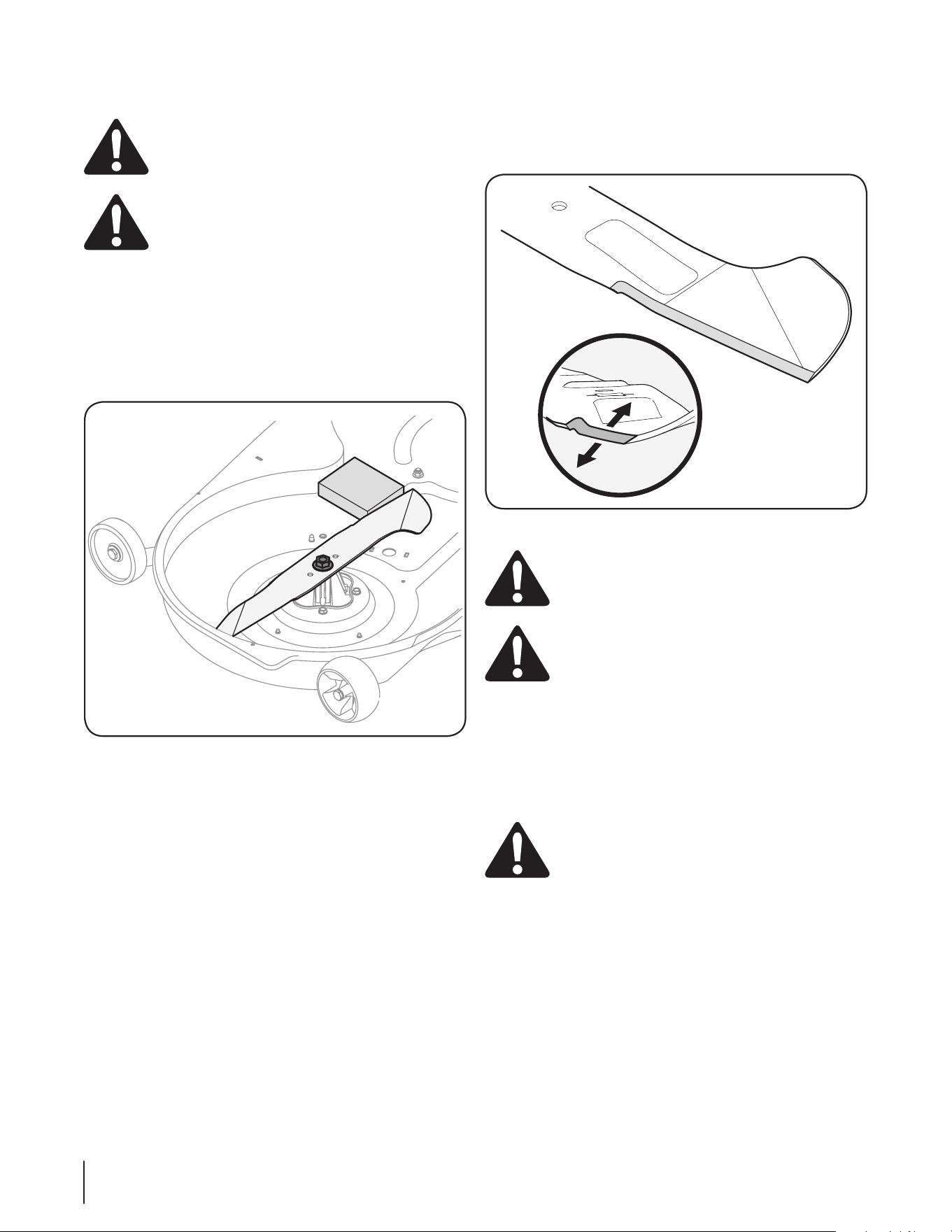
To remove the blades, proceed as follows.
Remove the deck from beneath the tractor, (refer to 1.
Cutting Deck Removal earlier in this section) then gently
flip the deck over to expose its underside.
Place a block of wood between the center deck housing 2.
baffle and the cutting blade to act as a stabilizer.
See Fig. 4-3.
Remove the hex flange nut that secures the blade to the 3.
spindle assembly. See Fig. 4-3.
To properly sharpen the cutting blades, remove equal 4.
amounts of metal from both ends of the blades along the
cutting edges, parallel to the trailing edge, at a 25°- to 30°
angle. Always grind each cutting blade edge equally to
maintain proper blade balance. See Fig. 4-4.
CAUTION: If the cutting edge of the blade has
previously been sharpened, or if any metal
separation is present, replace the blades with new
ones.
WARNING! A poorly balanced blade will cause
excessive vibration, may damage to the tractor and/
or result in personal injury.
Test the blade’s balance using a blade balancer. Grind 5.
metal from the heavy side until it balances evenly.
NOTE: When replacing the blade, be sure to install the
blade with the side of the blade marked ‘‘Bottom’’ (or with
a part number stamped in it) facing the ground when the
mower is in the operating position.
CAUTION: Use a torque wrench to tighten the
blade spindle hex flange nut to between 110 lbs-ft
and 130 lbs-ft.
Figure 4-3
Figure 4-4
8 se c t i O n 4— se r v i c e
Changing the Deck Belt
WARNING! The V-belts found on your tractor are
specially designed to engage and disengage safely.
A substitute (non-OEM) V-belt can be dangerous by
not disengaging completely. For a proper working
machine, use factory approved belts.
All belts on your tractor are subject to wear and should be
replaced if any signs of wear are present . To change or replace
the deck belt on your tractor, proceed as follows:
Remove the PTO belt as instructed earlier in this section 1.
under Cutting Deck Removal.
Remove the belt covers by removing the self-tapping 2.
screws that fasten them to the deck.
Working on the left side of the tractor, insert a ¹/3. 2-inch drive
ratchet wrench, set to loosen, into square hole found on the
idler bracket.
Pivot the wrench rearward to move the deck drive pulley 4.
forward and relieve tension on the deck belt.
Refer to Fig. 4-1.
WARNING! Avoid pinching injuries. Never place
your fingers on the idler spring or between the belt
and a pulley while removing the belt.
Carefully remove the deck belt from around the left-hand 5.
spindle pulley before slowly allowing the wrench to pivot
forward.
Carefully remove the deck belt from around the right-hand 6.
spindle pulley, center pulley on applicable models and
deck idler pulleys.
NOTE: The idler pulleys may have to be loosened, but not
removed, in order to remove the belt from around them.
Route the new belt as shown in the applicable figure on 7.
the following pages.
NOTE: Use a ¹/2-inch drive ratchet wrench as instructed in
earlier steps when routing the new belt.
Retighten idler pulleys, if loosened earlier.8.
Remount the belt guards removed earlier9.
19A40012100
9se c t i O n 4 — se r v i c e
19A40015100
19A40013100
10 se c t i O n 4— se r v i c e
19A40014100
19A40016100
11se c t i O n 4 — se r v i c e

IMPORTANT: To obtain warranty coverage owner may be required
to present an original proof of purchase and applicable maintenance
records to the servicing dealer. Please see the operator’s manual for
information on required maintenance and service intervals.
The limited warranty set forth below is given by Cub Cadet LLC with
respect to new merchandise purchased or leased and used in the United
States and/or its territories and possessions, and by MTD Products
Limited with respect to new merchandise purchased or leased and
used in Canada and/or its territories and possessions (either entity
respectively, “Cub Cadet”).
Cub Cadet warrants this product (excluding its Normal Wear Parts,
as described below) against defects in material and workmanship for
a period of two (2) years commencing on the date of original retail
purchase or lease and will, at its option, repair or replace, free of charge,
any part found to be defective in materials or workmanship.
Normal Wear Parts are warranted to be free from defects in material and
workmanship for a period of thirty (30) days from the date of original
purchase or lease. Normal wear parts include, but are not limited to
items such as: belts, blades, blade adapters, grass bags, rider deck
wheels, seats, and tires.
This limited warranty shall only apply if this product has been operated
and maintained in accordance with the Operator’s Manual furnished
with the product, and has not been subject to misuse, abuse, neglect,
accident, improper maintenance, alteration, vandalism, theft, fire, water,
or damage because of other peril or natural disaster. Damage resulting
from the installation or use of any part, accessory or attachment not
approved by Cub Cadet for use with the product(s) covered by this
manual will void your warranty as to any resulting damage. In addition,
Cub Cadet may deny warranty coverage if the hour meter, or any part
thereof, is altered, modified, disconnected or otherwise tampered with.
HOW TO OBTAIN SERVICE: Warranty service is available, WITH PROOF
OF PURCHASE AND APPLICABLE MAINTENANCE RECORDS, through
your local authorized service dealer. To locate the dealer in your area:
In the U.S.A.:
Check your Yellow Pages, or contact Cub Cadet LLC at P.O. Box 361131,
Cleveland, Ohio 44136-0019, call 1-877-282- 8684
or log on to our website at www.cubcadet.com.
In Canada:
Contact MTD Products Limited, Kitchener, ON N2G 4J1, call 1-800-668-
1238 or log on to our website at www.mtdcanada.com.
Without limiting the foregoing, this limited warranty does not provide
coverage in the following cases:
a. Routine maintenance items such as lubricants, filters, blade
sharpening, tune-ups, brake adjustments, clutch adjustments, deck
adjustments, and normal deterioration of the exterior finish due to
use or exposure.
b. Service completed by someone other than an authorized service
dealer.
c. Cub Cadet does not extend any warranty for products sold or
exported outside of the United States and/or Canada, and their
respective possessions and territories, except those sold through
Cub Cadet’s authorized channels of export distribution.
d. Replacement parts and\or accessories that are not genuine Cub
Cadet parts.
e. Transportation charges and service calls.
f. Commercial or Institutional Use.
There are no implied warranties, including without limitation any
implied warranty of merchantability or fitness for a particular
purpose. No warranties shall apply after the applicable period of
express written warranty above. No other express warranties beyond
those mentioned above, given by any person or entity, including a
dealer or retailer, with respect to any product, shall bind Cub Cadet.
The exclusive remedy is repair or replacement of the product as
set forth above. The terms of this warranty provide the sole and
exclusive remedy arising from the sale and/or lease of the products
covered hereby. Cub Cadet shall not be liable for any incidental or
consequential loss or damage including, without limitation, expenses
incurred for substitute or replacement lawn care services or for rental
expenses to temporarily replace a warranted product.
Some jurisdictions do not allow the exclusion or limitation of incidental
or consequential damages, or limitations on how long an implied
warranty lasts, so the above exclusions or limitations may not apply to
you.
In no event shall recovery of any kind be greater than the amount of the
purchase price of the product sold. Alteration of safety features of the
product shall void this warranty. You assume the risk and liability for
loss, damage, or injury to you and your property and/or to others and
their property arising out of the misuse or inability to use the product.
This limited warranty shall not extend to anyone other than the original
purchaser or to the person for whom it was purchased as a gift.
HOW LOCAL LAWS RELATE TO THIS WARRANTY: This limited warranty
gives you specific legal rights, and you may also have other rights that
vary in different jurisdictions.
CUB CADET LLC
MANUFACTURER’S LIMITED WARRANTY
FOR SEPARATELY SOLD ATTACHMENTS AND ACCESSORIES
Cub Cadet LLC, P.O. BOX 361131 CLEVELAND, OHIO 44136-0019, Phone: 1-877-282-8684
MTD Products Limited, Kitchener, ON N2G 4J1, Phone: 1-800-668-1238
GDOC-100177 REV. A