
2026
PASSPORT
Owner’s Manual
California Proposition 65 Warning
WARNING: Operating, servicing and maintaining a
passenger vehicle or off-highway motor vehicle can
expose you to chemicals including engine exhaust,
carbon monoxide, phthalates, and lead, which are
known to the State of California to cause cancer and
birth defects or other reproductive harm.
To minimize exposure, avoid breathing exhaust, do
not idle the engine except as necessary, service your
vehicle in a well-ventilated area and wear gloves or
wash your hands frequently when servicing your
vehicle. For more information go
towww.P65Warnings.ca.gov/passenger-vehicle.
A Few Words About Safety
Your safety, and the safety of others, is very important. Operating this vehicle safely is
an impor
tant responsibility.
To help you make informed decisions about safety, we have provided operating
procedures and other information on labels and in this manual. This information
alerts you to potential hazards that could hurt you or others.
Of course, it is not practical or possible to warn you about all the hazards associated
with operating or maintaining your vehicle. You must use your own good judgment.
You will find this important safety information in a variety of forms, including:
Safety Labels - on the vehicle.
Safety Messages - preceded by a safety alert symbol and one of three signal words:
DANGER, WARNING, or CAUTION. These signal words mean:
3 DANGER
You WILL be KILLED or SERIOUSLY HURT if you don’t follow instructions.
3 WARNING
You CAN be KILLED or SERIOUSLY HURT if you don’t follow instructions.
General Information
General Information
1

3 CAUTION
You CAN be HURT if you don’t follow instructions.
Safety Headings - such as Important Safety Precautions.
Safety Section - such as Safe Driving.
Instructions - how to use this vehicle correctly and safely.
This entire book is fil
led with important safety information - please read it carefully.
About Other Displays
This mark denotes advice for preventing vehicle damage or malfunction, or that you
should be careful when using something.
Indicates that a feature is customizable.
About This Manual
This owner’s manual should be considered a permanent part of the vehicle and
should r
emain with the vehicle when it is sold.
This owner’s manual covers all models of your vehicle. You may find descriptions of
equipment and features that are not on your particular model.
The images throughout this owner’s manual (including the front cover) that depict
features, equipment, Audio/Information screen details, and Meter screens are only
examples and may not be representative of your particular model.
This owner’s manual is for vehicles sold in the United States and Canada.
The information and specifications included in this publication were in effect at the
time of approval for printing. Honda Motor Co., Ltd. reserves the right, however, to
discontinue or change specifications or design at any time without notice and without
incurring any obligation.
System Updates Terms & Conditions
General
General Information
2

Your vehicle has an application that allows your System Updates to automatically
search for Honda software updates that are specific to your System Updates and its
connected devices (when you set the power mode to ON, via Wi-Fi or every four (4)
weeks via Telematics Control Unit (TCU)
*
, queries may occur more or less frequently
due to internet outages, retries, direct user action, WAP push from the server, or a
change in query policy on the Honda servers). This application periodically transmits
to our servers a limited amount of vehicle and device information (Vehicle
Identification Number (VIN), the Model Type (MT) Identification Number, Hardware
and Software Part Number, Serial Number, Software Version, preferred language,
Internet Protocol (IP) address, Transaction Log (alert or update viewing, update
download and installation, software status), etc.). When the application finds an
update from the server, the application initially asks permission to download and
install the update. Where available, in your settings menu you may elect to
automatically download and install these updates or you may elect to manually
update the system.
When your System Updates searches our servers for updates or alerts, we will
aut
omatically provide you with the opportunity to update your devices or transmit the
update or alert directly to your System Updates. We will also maintain on our servers
a log of the updates or alerts that are installed.
Your Personal Data
Should the aforementioned information transmitted to Honda constitute personal
inf
ormation in your region, please note that this information will be treated in strict
accordance with the rules and regulations outlined in this notice as well as applicable
data protection law.
The terms of our privacy notice are incorporated into these terms by reference and
your use of system updates will be subject to the privacy notice. Our privacy notice
sets out information about how we and any named third-parties will process any
personal data we collect from you or that you provide to us, via the application.
For further details, see Honda’s vehicle data privacy notice at:
U.S.: https://www.honda.com/privacy/connected-product-privacy-notice
Canada: https://www.honda.ca/privacy/vehicledata (English)
https://www.honda.ca/fr/confidentialite/politiquedeconfidentialité (French)
Honda collects, uses, and stores your personal data for the reasons set out below:
to deliver the system updates and related services to you;
to allow us to improve and optimize the system updates products and services;
to respond to user questions and complaints; and for internal record keeping.
where necessary for Honda’s legitimate interests, as listed below, and where our interests are
not overridden by your data protection rights.
as otherwise described in Honda’s Privacy Notice and Vehicle Data Privacy Notice
*: Not available on all models
General Information
3

Protecting our legitimate business interests and legal rights includes, but is not
limited to, use in connection with compliance, regulatory, auditing, legal claims
(including disclosure of such information in connection with legal process or
litigation), and other ethics and compliance reporting requirements.
Honda will also convert personal data into anonymous data and use it (normally on an
aggregated statistical basis) for uses such as market research and analysis, to
improve the system updates, to analyze trends, and to assess the success of software
update releases. Aggregated personal information does not personally identify you or
any other use of the system updates.
Honda may share this data with Honda’s worldwide support organization or affiliated
Honda companies or other third-parties engaged by Honda for the purposes of
rendering support services in connection with system support.
Event Data Recorders
This vehicle is equipped with an event data recorder (EDR).
The main purpose of an EDR is to record, in certain crash or near crash-like situations,
such as an air bag deplo
yment or hitting a road obstacle, data that will assist in
understanding how a vehicle’s systems performed. The EDR is designed to record
data related to vehicle dynamics and safety systems for a short period of time,
typically 30 seconds or less. The EDR in this vehicle is designed to record such
data as:
How various systems in your vehicle were operating;
Whether or not the driver and passenger safety belts were buckled/fastened;
How far (if at all) the driver was depressing the accelerator and/or brake pedal; and,
How fast the vehicle was traveling.
These data can help provide a better understanding of the circumstances in which
cr
ashes and injuries occur. NOTE: EDR data are recorded by your vehicle only if a non-
trivial crash situation occurs; no data are recorded by the EDR under normal driving
conditions and no personal data (e.g., name, gender, age, and crash location) are
recorded. However, other parties, such as law enforcement, could combine the EDR
data with the type of personally identifying data routinely acquired during a crash
investigation.
To read data recorded by an EDR, special equipment is required, and access to the
vehicle or the EDR is needed. In addition to the vehicle manufacturer, other parties,
such as law enforcement, that have the special equipment, can read the information
if they have access to the vehicle or the EDR.
The data belongs to the vehicle owner and may not be accessed by anyone else
except as legally required or with the permission of the vehicle owner.
General Information
4

Service Diagnostic Recorders
This vehicle is equipped with service-related devices that record information about
po
wertrain performance. The data can be used to verify emissions law requirements
and/or help technicians diagnose and solve service problems. It may also be
combined with data from other sources for research purposes, but it remains
confidential. Some diagnostic and maintenance information is uploaded to Honda
upon vehicle start up.
California Perchlorate Contamination
Prevention Act
The airbags, seat belt tensioners, and CR type batteries in this vehicle may contain
per
chlorate materials - special handling may apply. See www.dtsc.ca.gov/
hazardouswaste/perchlorate
Software End User License Agreement
Your vehicle comes equipped with software, which is governed by the End User
Lic
ense Agreement in Owner’s Manual, and which contains a binding arbitration
clause. Please refer to the End User License Agreement for the terms and conditions
governing your use of the installed software, as well as the applications, services,
functions, and content provided through the software. Your use of the installed
software will serve as your consent to the terms and conditions of the End User
License Agreement.
You may opt out within 30 days of your initial use of the Software by sending a signed,
written notice to HONDA at American Honda Motor Co., Inc., Honda Automobile
Customer Service, Mail Stop CHI-5, 1919 Torrance Blvd., Torrance, CA 90501-2746.
Privacy Notice
This vehicle may share location and usage information. To manage this setting, visit
at:
U.S.: ht
tps://mygarage.honda.com/s/vehicle-data-privacy-settings?page=question
Canada: https://www.honda.ca/privacy/vehicledata (English)
https://www.honda.ca/fr/confidentialite/politiquedeconfidentialité (French)
To learn more about how we collect and use Personal Information including
precise geolocation data, please read our Privacy Notice and Vehicle Data
Privacy Notice, accessible at:
U.S.: ht
tps://www.honda.com/privacy/connected-product-privacy-notice
Canada: https://www.honda.ca/privacy/vehicledata (English)
General Information
5


1 Before Driving 13
Check Before Drivingu 14 | Safety Labels u 46 | Keyu 47 | Locking/Unlocking u 52 |
Steering Wheelu 63 | Seats u 64 | Seat Belts u 73 | Mirrors u 80 | Windows u 82 | Tailgate u 85 |
Maximum Load Limit u 92 | Towing a Traileru 95 | Off-Highway Driving Guidelines u 104
2 Driving Operation 109
Starting or Stopping the Engineu 110 | Shifting u 115 | Braking u 120 | Starting and Drivingu 127 |
Parking Your Vehicle u 129 | Rear View Camera
*
u 130 | Multi View Camera System
*
u 132 |
Refueling u 141 | Fuel Economy and CO2 Emissionsu 144 | Turn Signals/Light Switchesu 145 |
Wipers and Washers u 152 | Defrosteru 156 | Heated Windshield Button
*
u 158 | Driving Features u 159
3 Controls 173
Interior Lightsu 174 | Interior Convenience Itemsu 176 | Seat Heaters/Ventilators u 188 |
Heated Steering Wheel
*
u 190 | Panoramic Roof
*
u 191 | Climate Control System u 194 |
In-Vehicle Infotainment u 199 | 12.3″ Color Touchscreen u 208 |
General Information on the Audio Systemu 249
4 Safety Driving Assist System 266
Honda Sensing® u 267 | Collision Mitigation Braking System™(CMBS™) u 274 |
Low Speed Braking Controlu 280 | Road Departure Mitigation System u 285 |
Adaptive Cruise Control (ACC) with Low Speed Followu 289 | Lane Keeping Assist System (LKAS)u 300 |
Traffic Jam Assist u 304 | Traffic Sign Recognition System u 308 | Blind Spot Information Systemu 311 |
Cross Traffic Monitor u 314 | Parking Sensor System u 318
5 About Your Instrument Panel 322
Indicators u 323 | Gauges u 330 | Driver Information Interfaceu 334
6 Maintenance 344
Before Performing Maintenanceu 345 | Maintenance Minder™u 348 | Maintenance Under the Hood u 353 |
Checking and Maintaining Wiper Blades u 363 | Checking and Maintaining Tires u 367 |
12-Volt Battery u 376 | Climate Control System Maintenanceu 378 | Cleaning u 379
7 Handling the Unexpected 383
Tools u 384 | When a lightbulb goes out u 385 | Remote Transmitter Careu 387 |
If a Tire Goes Flat u 389 | Engine Does Not Start u 395 | If the 12-volt Battery Is Dead u 397 |
Overheating u 399 | When a Warning Appearsu 401 | Fusesu 402 | Emergency Towing u 409 |
If You Cannot Unlock the Fuel Fill Door u 410 | If You Cannot Open the Tailgate u 411 | Refueling u 412 |
Emergency Call (eCall)u 413
8 Vehicle Information 415
Specificationsu 416 | Identification Numbers u 418 | Devices that Emit Radio Waves u 419 |
Reporting Safety Defectsu 420 | Emissions Testingu 422 | Warranty Coveragesu 424 |
Authorized Manualsu 426 | Customer Service Informationu 427 | Open Source Licenseu 429
*: Not available on all models
Contents
7
1
2
3
4
5
6
7
8
Index
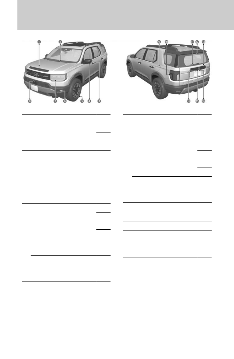
a
Maintenance Under the Hood
u
353
b
Windshield Wipers
u
152
u
363
c
Door Lock/Unlock Control
u
52
d
Power Door Mirrors
u
80
Side Turn Signal Lights
*
u
145
Multi View Camera System
*
u
132
e
Tires
u
367
f
Fog Lights
*
u
148
u
385
g
Headlights
u
145
u
385
Front Turn Signal Lights
u
145
u
385
Front Side Marker Lights
u
145
u
385
Parking Lights/Daytime Running
Lights
u
145
u
148
u
385
h
Multi View Camera System
*
u
132
i
How to Refuel
u
142
j
Brake/Taillights
u
385
Rear Side Marker Lights
u
145
u
385
Rear Turn Signal Lights
u
145
u
385
Back-Up Lights
u
385
k
Rear Wiper
u
155
u
365
l
High-Mount Brake Light
u
385
m
Opening/Closing the Tailgate
u
85
n
Rear License Plate Light
u
385
o
Tailgate Outer Handle
u
87
p
Rear View Camera
*
u
130
Multi View Camera System
*
u
132
*: Not available on all models
Visual Index
8
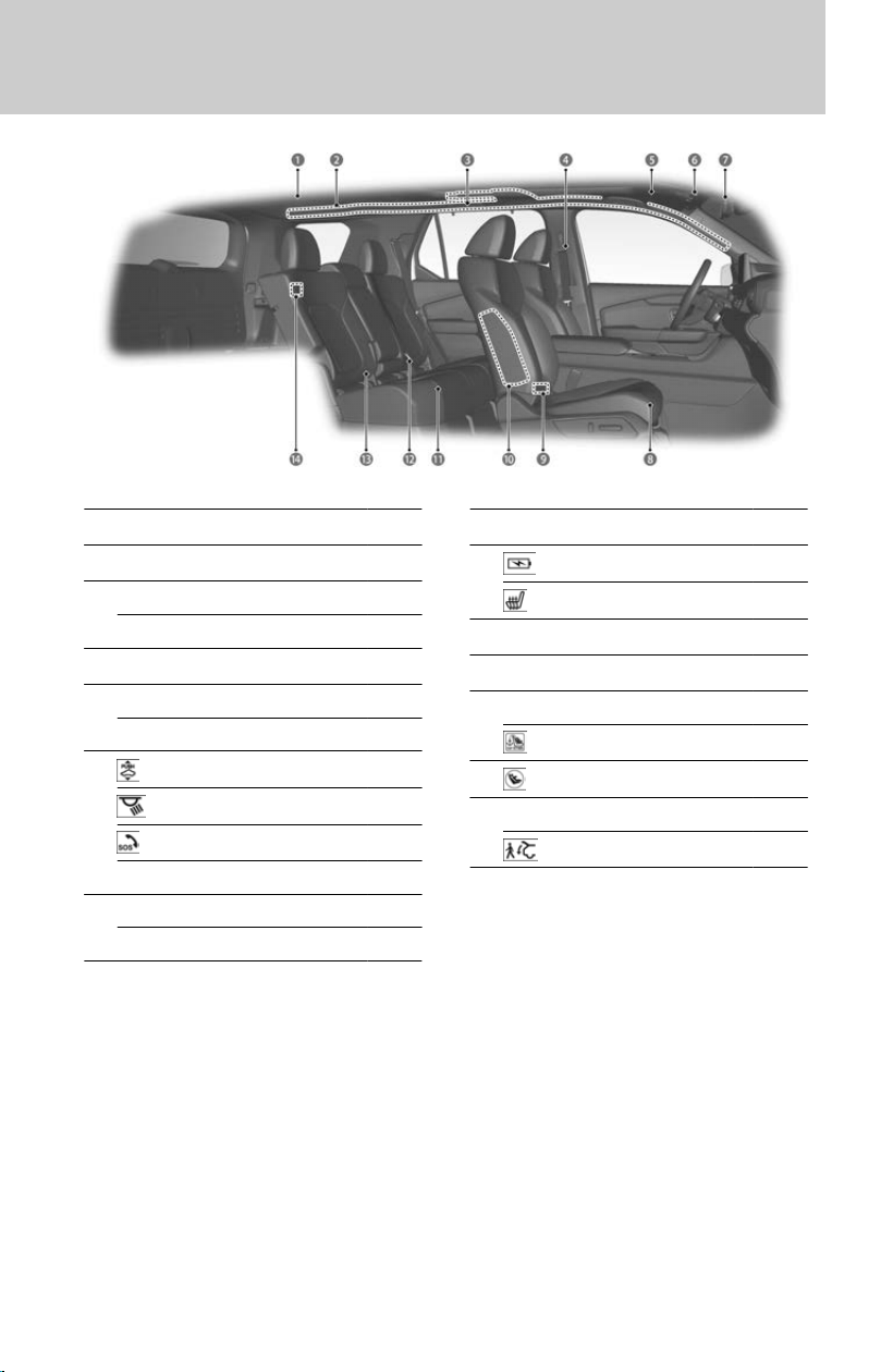
a
Cargo Area Light
u
175
b
Side Curtain Airbags
u
41
c
Grab Handle
Coat Hook
u
181
d
Seat Belts
u
73
e
Sun Visors
Vanity Mirrors
f
Panoramic Roof Switch
*
u
191
Map Lights
u
174
SOS Button
u
414
Sunglasses Holder
u
182
g
Rearview Mirror
u
80
HomeLink® Buttons
*
u
184
h
Front Seat
u
66
i
USB Ports
u
202
Rear Outer Seat Heater Buttons
*
u
189
j
Side Airbags
u
40
k
Rear Seats
u
68
l
Seat Belt (Installing a Child Seat)
u
25
Seat Belt to Secure a Child Seat
u
27
m
LATCH to Secure a Child Seat
u
23
n
Accessory Power Socket
*
u
176
Walk Away Close Button
*
u
89
*: Not available on all models
Visual Index
9
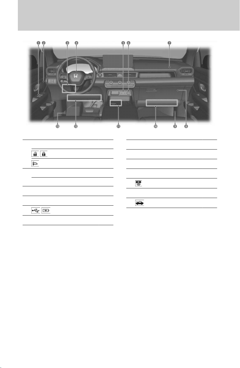
a
Power Window Switches
u
82
Master Door Lock Switch
u
59
Door Mirror Controls
u
80
b
Memory Buttons
u
70
SET Button
u
70
c
Interior Fuse Box
u
404
d
Driver’s Front Airbag
u
34
e
USB Ports
u
202
f
Accessory Power Socket
u
176
g
Passenger’s Front Airbag
u
34
h
Glove Box
u
176
i
Interior Fuse Box
u
406
j
Passenger’s Knee Airbag
u
38
k
Wireless Charger
u
179
l
Driver’s Knee Airbag
u
38
m
Hood Release Handle
u
353
Visual Index
10
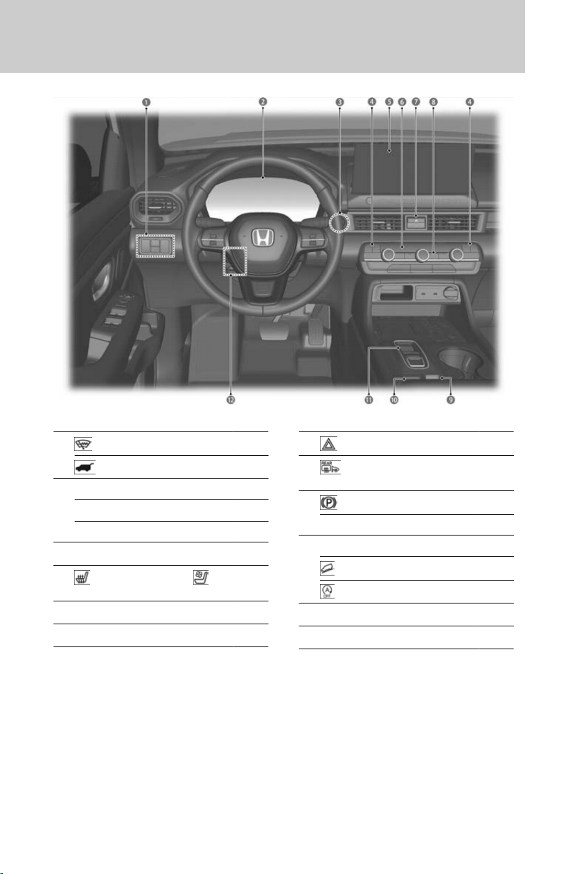
a
Heated Windshield Button
*
u
158
Power Tailgate Button
u
88
b
System Indicators
u
323
Gauges
u
330
Driver Information Interface
u
334
c
ENGINE START/STOP But
ton
u
110
d
Front Seat Heaters and Seat
Ventilator
*
Buttons
u
188
e
Audio System
u
199
f
Climate Control System
u
194
g
Hazard Warning Button
h
Rear Defogger/Heated Door
Mirror Button
u
156
i
Electric Parking Brake Switch
u
121
Automatic Brake Hold Button
u
124
j
DRIVE MODE Swit
ch
u
159
Hill Descent Control Button
u
165
Auto Idle Stop OFF Button
u
162
k
Shift Button
u
115
l
Steering Wheel Adjustments
u
63
*: Not available on all models
Visual Index
11
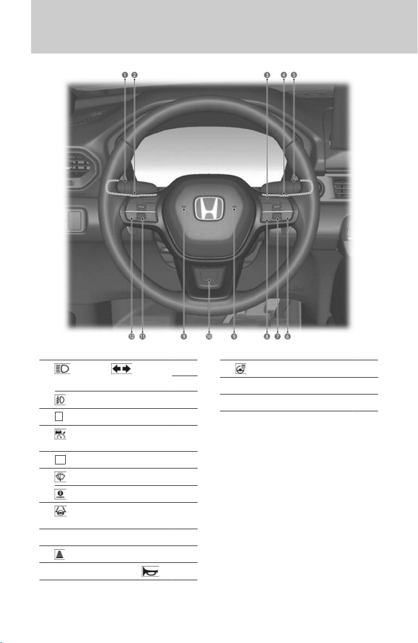
a
Headlights/ Turn
Signals
u
145
u
145
Fog Lights
*
u
148
b
−
Paddle Shifter (Shift down)
u
118
c
Adaptive Cruise Control (ACC)
with Low Speed Follow Buttons
u
290
d
+
Paddle Shifter (Shift up)
u
118
e
Wipers/Washers
u
152
CAMERA Button
*
u
133
f
Lane Keeping Assist System
(LKAS) Button
u
301
g
Right Selector Wheel
u
334
h
Interval Button
u
293
i
Horn (Press an area around
.)
j
Heated Steering Wheel Button
*
u
190
k
Left Selector Wheel
u
342
l
Audio Remote Controls
u
203
*: Not available on all models
Visual Index
12

Check Before Driving
For Safe Driving・・・・・・・・・・・・・・・・・・・・・・・・・・・・・・・・・14
Important Handling Information・・・・・・・・・・・・・・・・ 15
Your Vehicle’s Safety Features・・・・・・・・・・・・・・・・・・ 16
Driving Preparation・・・・・・・・・・・・・・・・・・・・・・・・・・・・・・17
Precautions While Driving・・・・・・・・・・・・・・・・・・・・・・・ 19
Child Safety・・・・・・・・・・・・・・・・・・・・・・・・・・・・・・・・・・・・・ 19
Safety of Infants and Small Children・・・・・・・・・・・ 20
Installing a Child Seat・・・・・・・・・・・・・・・・・・・・・・・・・・ 23
Safety of Larger Children・・・・・・・・・・・・・・・・・・・・・・・・ 28
Exhaust Gas Hazard・・・・・・・・・・・・・・・・・・・・・・・・・・・・・30
Modifications and Accessories・・・・・・・・・・・・・・・・・・ 31
About Your Airbags・・・・・・・・・・・・・・・・・・・・・・・・・・・・・・32
Airbag System Components・・・・・・・・・・・・・・・・・・・・・33
Front Airbags (SRS)・・・・・・・・・・・・・・・・・・・・・・・・・・・・・34
Knee Airbags・・・・・・・・・・・・・・・・・・・・・・・・・・・・・・・・・・・ 38
Side Airbags・・・・・・・・・・・・・・・・・・・・・・・・・・・・・・・・・・・・ 40
Side Curtain Airbags・・・・・・・・・・・・・・・・・・・・・・・・・・・・ 41
Airbag System Indicators・・・・・・・・・・・・・・・・・・・・・・・42
Airbag Care・・・・・・・・・・・・・・・・・・・・・・・・・・・・・・・・・・・・・ 44
Safety Labels
Label Locations・・・・・・・・・・・・・・・・・・・・・・・・・・・・・・・・・ 46
Key
Details on the Key・・・・・・・・・・・・・・・・・・・・・・・・・・・・・・・47
Built-in Key・・・・・・・・・・・・・・・・・・・・・・・・・・・・・・・・・・・・・・50
Key Number Tag・・・・・・・・・・・・・・・・・・・・・・・・・・・・・・・・・51
Locking/Unlocking
Using the Remote Transmitter・・・・・・・・・・・・・・・・・・ 52
Using the Keyless Access System・・・・・・・・・・・・・・・ 53
Locking the Doors and Tailgate (Walk Away Auto
Lock®)・・・・・・・・・・・・・・・・・・・・・・・・・・・・・・・・・・・・・・・・・・55
Lock Presetting・・・・・・・・・・・・・・・・・・・・・・・・・・・・・・・・・・57
Unlocking the Doors Using a Key・・・・・・・・・・・・・・・・ 57
Locking a Door Without Using a Key・・・・・・・・・・・・・58
Locking/Unlocking the Doors from the Inside・・・ 59
Auto Door Locking/Unlocking・・・・・・・・・・・・・・・・・・・ 60
Childproof Door Locks・・・・・・・・・・・・・・・・・・・・・・・・・・・61
What to Do If・・・・・・・・・・・・・・・・・・・・・・・・・・・・・・・・・・・・ 61
Steering Wheel
Adjus
ting the Steering Wheel・・・・・・・・・・・・・・・・・・・ 63
Seats
Adjusting the Seat・・・・・・・・・・・・・・・・・・・・・・・・・・・・・・・64
Adjusting the Front Seat Positions・・・・・・・・・・・・・・ 66
Adjusting the Rear Outer and Center Seat
Positions・・・・・・・・・・・・・・・・・・・・・・・・・・・・・・・・・・・・・・・68
Driving Position Memory System・・・・・・・・・・・・・・・・ 70
Rear Seat Reminder・・・・・・・・・・・・・・・・・・・・・・・・・・・・・71
Seat Belts
About Your Seat Belts・・・・・・・・・・・・・・・・・・・・・・・・・・・ 73
Fastening a Seat Belt・・・・・・・・・・・・・・・・・・・・・・・・・・・ 76
Adjusting the Shoulder Anchor・・・・・・・・・・・・・・・・・ 78
Mirrors
Interior Rearview Mirror・・・・・・・・・・・・・・・・・・・・・・・・・80
Power Door Mirrors・・・・・・・・・・・・・・・・・・・・・・・・・・・・・ 80
Windows
Opening/Closing the Power Windows・・・・・・・・・・・ 82
Opening the Windows with the Remote・・・・・・・・・ 84
Tailgate
Precautions for Opening/Closing the Tailgate・・・ 85
Opening/Closing the Power Tailgate・・・・・・・・・・・・ 87
Maximum Load Limit
About Maximum Load Limit・・・・・・・・・・・・・・・・・・・・・ 92
Towing a Trailer
Towing Preparation・・・・・・・・・・・・・・・・・・・・・・・・・・・・・ 95
Trailer Stability Assist・・・・・・・・・・・・・・・・・・・・・・・・・ 101
Driving Safely with a Trailer・・・・・・・・・・・・・・・・・・・・101
Towing Behind a Motorhome・・・・・・・・・・・・・・・・・・ 103
Off-Highway Driving Guidelines
General Information・・・・・・・・・・・・・・・・・・・・・・・・・・・ 104
Important Safety Precautions・・・・・・・・・・・・・・・・・ 104
Avoiding Trouble・・・・・・・・・・・・・・・・・・・・・・・・・・・・・・・105
Off-Highway Driving・・・・・・・・・・・・・・・・・・・・・・・・・・・ 106
Before Driving
13

1
Before Driving >
Check Before Driving
For Safe Driving
The following pages explain your vehicle’s safety features and how to use them
pr
operly. The safety precautions below are ones that we consider to be among the
most important.
Important Safety Precautions
Some states, provinces, and territories prohibit the use of cell phones other than
hands
-free devices by the driver while driving.
Always wear your seat belt
A seat belt is your best protection in all types of collisions. Airbags are designed to
supplement seat bel
ts, not replace them. So even though your vehicle is equipped
with airbags, make sure you and your passengers always wear your seat belts, and
wear them properly.
Restrain all children
Children ages 12 and under should ride properly restrained in a back seat, not the
fr
ont seat. Infants and small children should be restrained in a child seat. Larger
children should use a booster seat and a lap/shoulder seat belt until they can use
the belt properly without a booster seat.
Be aware of airbag hazards
While airbags can save lives, they can cause serious or fatal injuries to occupants
who sit t
oo close to them, or are not properly restrained. Infants, young children,
and short adults are at the greatest risk. Be sure to follow all instructions and
warnings in this manual.
Don’t drink and drive
Alcohol and driving don’t mix. Even one drink can reduce your ability to respond to
changing c
onditions, and your reaction time gets worse with every additional drink.
So don’t drink and drive, and don’t let your friends drink and drive, either.
Pay appropriate attention to the task of driving safely
Engaging in cell phone conversation or other activities that keep you from paying
close at
tention to the road, other vehicles, and pedestrians could lead to a crash.
Remember, situations can change quickly, and only you can decide when it is safe
to divert some attention away from driving.
14

Control your speed
Excessive speed is a major factor in crash injuries and deaths. Generally, the higher
the speed, the gr
eater the risk, but serious injuries can also occur at lower speeds.
Never drive faster than is safe for current conditions, regardless of the maximum
speed posted.
Keep your vehicle in safe condition
Having a tire blowout or a mechanical failure can be extremely hazardous. To
r
educe the possibility of such problems, check your tire pressures and condition
frequently, and perform all regularly scheduled maintenance.
Do not leave children unattended in the vehicle
Children, pets, and people needing assistance left unattended in the vehicle may be
injur
ed if they activate one or more of the vehicle controls. They may also cause the
vehicle to move, resulting in a crash in which they and/or another person(s) can be
injured or killed. Also, depending on the ambient temperature, the temperature of
the interior may reach extreme levels, which can result in harm or death. Even if the
climate control system is on, never leave them in the vehicle unattended as the
climate control system can shut off at any time.
Important Handling Information
Your vehicle has higher ground clearance than a passenger vehicle designed for use
onl
y on pavement. Higher ground clearance has many advantages for off-highway
driving. It allows you to travel over bumps, obstacles, and rough terrain. It also
provides good visibility so you can anticipate problems earlier.
These advantages come at some cost. Because your vehicle is taller and rides higher
off the ground, it has a higher center of gravity making it more susceptible to tipping
or rollover if you make abrupt turns. Utility vehicles have a significantly higher rollover
rate than other types of vehicles. In a rollover crash, an unbelted person is
significantly more likely to die than a person wearing a seat belt. As a reminder, make
sure you and your passengers always wear seat belts.
For information on how to reduce the risk of rollover, read:
Driving Guidelines for Your Utility Vehicle
u
P.128
General Information
u
P.104
Failure to operate your vehicle correctly might result in a crash or a rollover.
1
Before Driving > Check Before Driving
15
1
Before Driving
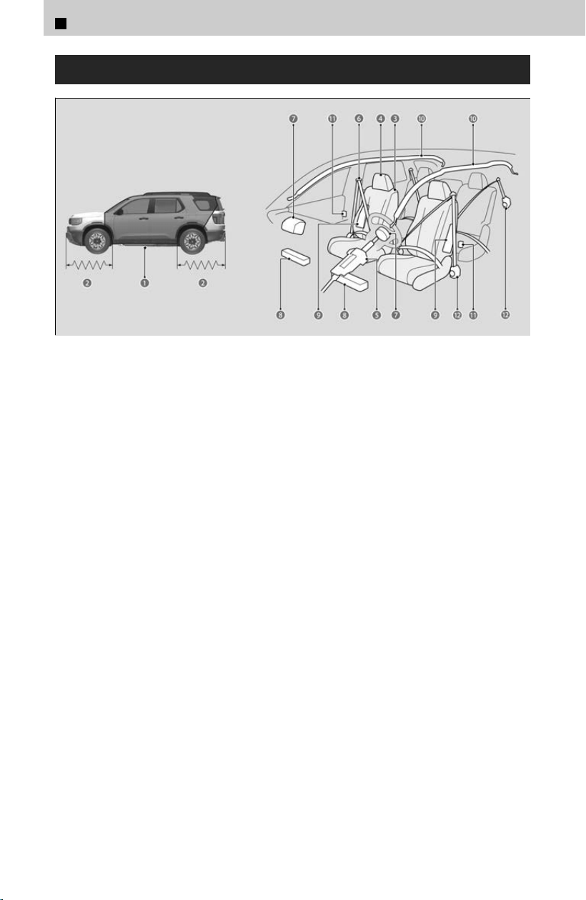
Your Vehicle’s Safety Features
a Safety Cage
b Crush Zones
c Seats and Seat-Backs
d Head Restraints
e Collapsible Steering Column
f Seat Belts
g Front Airbags
h Knee Airbags
i Side Airbags
j Side Curtain Airbags
k Door Locks
l Seat Belt Tensioners
The following checklist will help you take an active role in protecting yourself and your
pas
sengers.
Your vehicle is equipped with many features that work together to help protect you
and your passengers during a crash.
Some features do not require any action on your part. These include a strong steel
framework that forms a safety cage around the passenger compartment, front and
rear crush zones, a collapsible steering column, and tensioners that tighten the front
and rear seat belts in a sufficient crash.
However, you and your passengers cannot take full advantage of these features
unless you remain seated in the correct position and always wear your seat belts. In
fact, some safety features can contribute to injuries if they are not used properly.
1
Before Driving > Check Before Driving
16
Driving Preparation
Exterior Checks
Make sure there are no people or objects behind or around the vehicle.
≫
There are blind spots from the inside.
Make sure the tires are in good condition.
≫
Check air pressures, and check for damage and excessive wear.
Checking Tires
u
P.367
Make sure the hood is securely closed.
≫
If the hood opens while driving, your front view will be blocked.
Make sure there are no obstructions on the windows, door mirrors, exterior lights, or other
parts of the vehicle.
≫
Remove any frost, snow, or ice.
≫
Remove any snow on the roof, as this can slip down and obstruct your field of vision while
driving or fall off and impact other road users. If frozen solid, remove ice once it has
softened.
≫
When removing ice from around the wheels, be sure not to damage the wheel or wheel
components.
Make sure the door is not frozen.
≫
When doors are frozen shut, use warm water around the door edges to melt any ice. Do not
try to force them open, as this can damage the rubber trim around the doors. When done,
wipe dry to avoid further freezing.
Make sure that there are no flammable materials left under the hood.
≫
Be especially careful if the vehicle has not been used for a long time, or after maintenance.
The heat from the engine and exhaust may cause flammable materials to catch fire, leading
to unexpected accidents.
Never carry more than 165 lbs (75 kg) of cargo on the roof rack (Honda accessory).
Interior Checks
After everyone has entered the vehicle, be sure all doors and the tailgate are closed and
locked. Locking the doors and the tailgate helps prevent an occupant from being ejected and
an outsider from unexpectedly opening a door or the tailgate.
Locking/Unlocking the Doors from the Inside
u
P.59
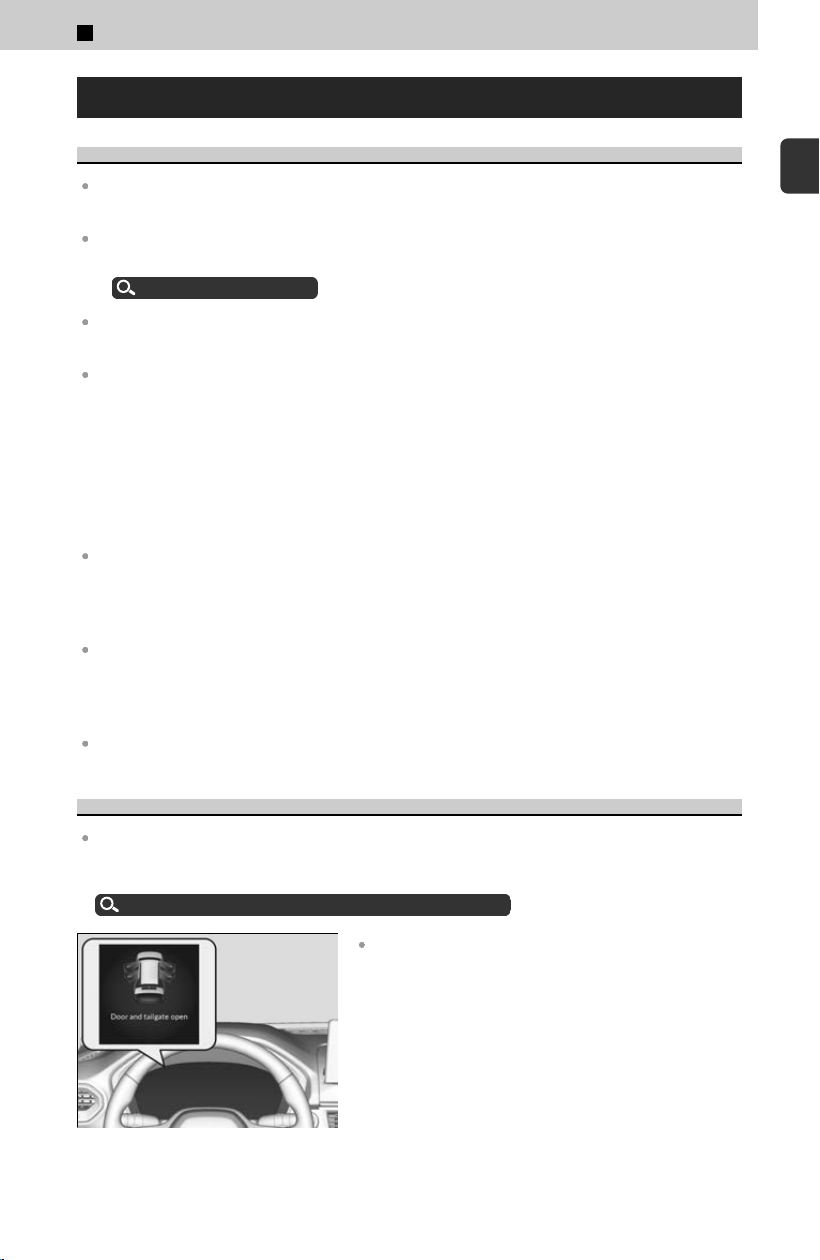
If the door and/or tailgate open message appears on
the driver information interface, a door and/or the
tailgate is not completely closed. Close all doors and
the tailgate tightly until the message disappears.
1
Before Driving > Check Before Driving
17
1
Before Driving

Adjust your seat to a position suitable for driving. Be sure the front seats are adjusted as far to
the rear as possible while allowing the driver to control the vehicle. Sitting too close to a front
airbag can result in serious or fatal injury in a crash.
Adjusting the Front Seat Positions
u
P.66
Adjusting the Seat
u
P.64
Adjust head restraints to the proper position. Head restraints are most effective when the
center of the head restraint aligns with the center of your head. Taller persons should adjust
their head restraint to the highest position.
Adjusting the Front Seat Positions
u
P.66
Always wear your seat belt, and make sure you wear it properly. Confirm that any passengers
are properly belted as well.
Fastening a Seat Belt
u
P.76
Protect children by using seat belts or child seats according to a child’s age, height, and
weight.
Child Safety
u
P.19
Do not place anything in the front seat footwells. Make sure to secure the floor mat.
≫
An object or unsecured floor mat can interfere with your brake and accelerator pedal
operation while driving.
Store or secure all items on board properly.
≫
Carrying too much cargo, or improperly storing it, can affect your vehicle’s handling,
stability, stopping distance, and tires, and make it unsafe.
About Maximum Load Limit
u
P.92
Do not pile items higher than the seatback height.
≫
They can block your view and may be thrown forward in the event of sudden braking.
Adjust the mirrors and steering wheel properly.
≫
Adjust them while sitting in the proper driving position.
Mirrors
u
P.80
Adjusting the Steering Wheel
u
P.63
Be sure items placed on the floor behind the front seats cannot roll under the seats.
≫
They can interfere with the driver’s ability to operate the pedals, the operation of the seats,
or the operation of the sensors under the seats.
If you have any animals on board, do not let them move around in the vehicle.
≫
They may interfere with driving and a crash could occur.
Make sure that the indicators in the instrument panel come on when you start the vehicle, and
go off soon after.
≫
Always have a dealer check the vehicle if a problem is indicated.
Indicator List
u
P.323
The headlight aim is set by the factory, and does not need to be adjusted. However, if
y
ou regularly carry heavy items in the cargo area or tow a trailer, have the aiming
readjusted at a dealer or by a qualified technician.
1
Before Driving > Check Before Driving
18

Precautions While Driving
In rain
Avoid driving in deep water and on flooded roads. This can damage the engine or
driv
eline, or cause electrical component failure.
Other precautions
If there is a strong impact with something under the vehicle, stop in a safe location.
Check the underside o
f the vehicle for damage or any fluid leaks.
If you repeatedly turn the steering wheel at an extremely low speed, or hold the
steering wheel in the full left or right position for a while, the electric power steering
(EPS) system heats up, causing the system to go into a protective mode and make
the steering wheel progressively harder to operate.
≫
Once the system cools down, the EPS system is restored.
≫
Repeated operation under these conditions can eventually damage the system.
Child Safety
Protecting Child Passengers
Each year, many children are injured or killed in vehicle crashes because they are
either unr
estrained or not properly restrained. In fact, vehicle crashes are the number
one cause of death of children ages 12 and under.
To reduce the number of child deaths and injuries, every state and Canadian province
and territory requires that infants and children be properly restrained when they ride
in a vehicle.
Children should sit properly restrained in a rear seat. This is because:
An inflating front airbag can injure or kill a child sitting in the front seat.
A child in the front seat is more likely to interfere with the driver’s ability to safely control the
vehicle.
Statistics show that children of all sizes and ages are safer when they are properly restrained
in a rear seat.
1
Before Driving > Check Before Driving
19
1
Before Driving

Never hold a child on your lap because it is impossible to protect them in the event of a
collision.
Never put a seat belt over yourself and a child. During a crash, the belt would likely press deep
into the child and cause serious or fatal injuries.
Never let two children use the same seat belt. Both children could be very seriously injured in
a crash.
Any child who is too small to wear a seat belt correctly must be restrained in an approved
child seat that is properly secured to the vehicle using either the seat belt or the lower
anchors of the LATCH system.
Do not allow children to operate the doors, windows, or seat adjustments.
Do not leave children in the vehicle unattended, especially in hot weather when the inside of
the vehicle can get hot enough to kill them. They could also activate vehicle controls causing it
to move unexpectedly.
The National Highway T
raffic Safety Administration and Transport Canada
recommend that all children ages 12 and under be properly restrained in a rear seat.
Some states or provinces/territories have laws restricting where children may ride.
To remind you of the passenger’s front airbag hazards and child safety, your vehicle
has warning labels on the dashboard (U.S. models) and on the front visors. Please
read and follow the instructions on these labels.
To deactivate a lockable retractor, release the buckle and allow the seat belt to wind
up all the way.
3 WARNING
Allowing a child to play with a seat belt or wrap one around their neck can
r
esult in serious injury or death.
Instruct children not to play with any seat belt and make sure any unused
seat belt a child can reach is buckled, fully retracted, and locked.
3 WARNING
Children who are unrestrained or improperly restrained can be seriously
injur
ed or killed in a crash.
Any child too small for a seat belt should be properly restrained in a child
seat. A larger child should be properly restrained with a seat belt, using a
booster seat if necessary.
Safety of Infants and Small Children
Protecting Infants
An infant must be properly restrained in a rear-facing child seat until the infant
r
eaches the seat manufacturer’s weight or height limit for the seat.
1
Before Driving > Check Before Driving
20
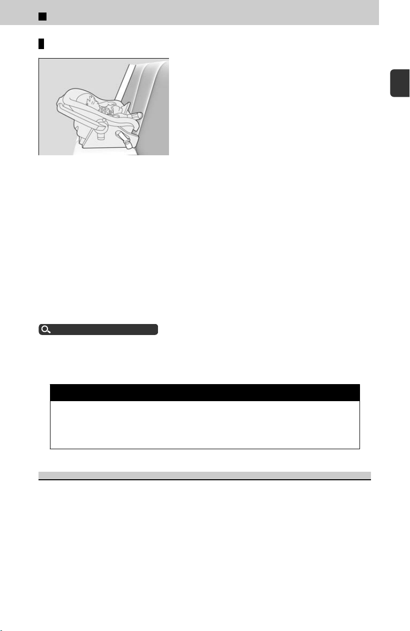
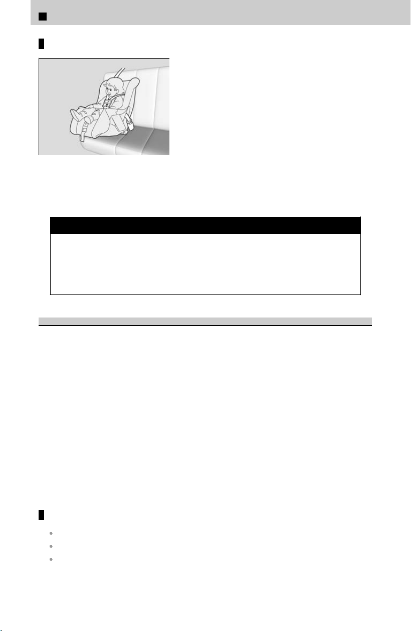
Positioning a rear-facing child seat
Child seats must be placed and secured in a rear
seating position.
Experts recommend use of a rear-facing seat for a child so long as the child’s height
and w
eight are appropriate for a rear-facing seat.
Infants should never be seated in a forward-facing position.
Always refer to the child seat manufacturer’s instructions before installation.
Do not allow a front seat to rest against a child seat installed in a rear seating position.
The weight sensor in the front seat may not correctly detect the actual weight of the
occupant.
When properly installed, a rear-facing child seat may prevent the driver or a front
passenger from moving their seat all the way back, or from locking their seat-back in
the desired position. Make sure that there is no contact between the child seat and
the seat in front of it.
It can also interfere with proper operation of the passenger’s advanced front airbag
system.
About Your Airbags
u
P.32
If this occurs, we recommend that you install the child seat directly behind the front
pas
senger’s seat, move the seat as far forward as needed, and leave it unoccupied.
Or, you may wish to get a smaller rear-facing child seat.
3 WARNING
Placing a rear-facing child seat in the front seat can result in serious injury
or death during a cr
ash.
Always place a rear-facing child seat in the rear seat, not the front.
Protecting Smaller Children
If a child has exceeded the weight and height limitations of a rear-facing child seat,
the child should be pr
operly restrained in a firmly secured forward-facing child seat
until they exceed the weight and height limitations for the forward-facing child seat.
Educate yourself about the laws and regulations regarding child seat use where you
are driving, and follow the child seat manufacturer’s instructions.
1
Before Driving > Check Before Driving
21
1
Before Driving
Forward-facing child seat placement
We strongly recommend placing a forward-facing
child seat in a rear seating position.
Placing a forward-facing child seat in the front seat can be hazardous, even with
adv
anced front airbags that automatically turn the passenger’s front airbag off. A rear
seat is the safest place for a child.
3 WARNING
Placing a forward-facing child seat in the front seat can result in serious
injur
y or death if the front airbag inflates.
If you must place a forward-facing child seat in front, move the vehicle seat
as far back as possible, and properly restrain the child.
Selecting a Child Seat
Most child seats are LATCH-compatible (Lower Anchors and Tethers for Children).
Some hav
e a rigid-type connector while others have a flexible-type connector. Both
are equally easy to use. Some existing and previously owned child seats can only be
installed using the seat belt. Whichever type you choose, follow the child seat
manufacturer’s use and care instructions including recommended expiration dates as
well as the instructions in this manual. Proper installation is key to maximizing your
child’s safety.
In seating positions and vehicles not equipped with LATCH, a LATCH-compatible child
seat can be installed using the seat belt and a top tether for added security. This is
because all child seats are required to be designed so that they can be secured with a
lap belt or the lap part of a lap/shoulder belt. In addition, the child seat manufacturer
may advise that a seat belt be used to attach a LATCH-compatible seat once a child
reaches a specified weight. Please read the child seat owner’s manual for proper
installation instructions.
Important consideration when selecting a child seat
The child seat is the correct type and size for the child.
The child seat is the correct type for the seating position.
The child seat is compliant with Federal Motor Vehicle Safety Standard 213 or Canadian
Motor Vehicle Safety Standard 213.
1
Before Driving > Check Before Driving
22
LATCH-compatible child seats have been developed to simplify the installation
process and reduce the likelihood of injuries caused by incorrect installation.
Installing a Child Seat
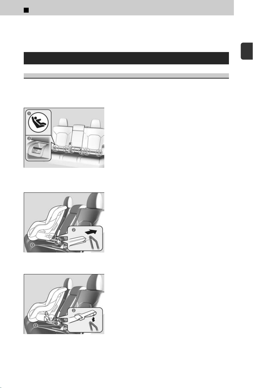
Installing a LATCH-Compatible Child Seat
A LATCH-compatible child seat can be installed in any of the three rear seating
positions
. A child seat is attached to the lower anchors with either the rigid or flexible
type of connectors.
a Marks
b Lower Anchors
[1] Locate the lower anchors under the marks.
a Lower Anchors
b Rigid Type
a Lower Anchors
b Flexible Type
[2] Place the child seat on the vehicle seat, then
at
tach the child seat to the lower anchors
according to the instructions that came with
the child seat.
≫
When installing the child seat, make sure that
the lower anchors are not obstructed by the
seat belt or any other object.
1
Before Driving > Check Before Driving
23
1
Before Driving
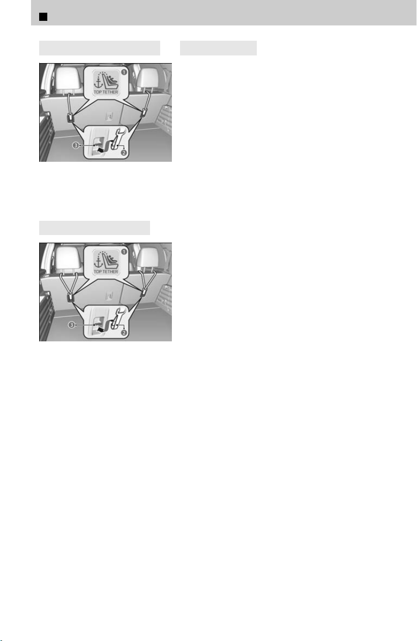
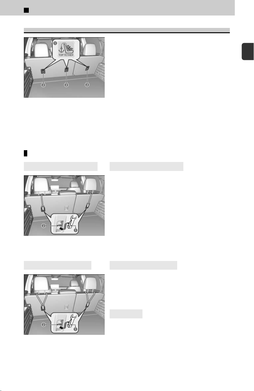
4
Straight Top Tether Type
a Top Tether Anchor Symbol
b Tether Strap Hook
c Anchor
4
Other Top Tether Type
a Top Tether Anchor Symbol
b Tether Strap Hook
c Anchor
4
Outer position
[3] Raise the outer head restraint to its highest
position, then r
oute the tether strap as
shown in the image.
Make sure the strap is not twisted.
1
Before Driving > Check Before Driving
24
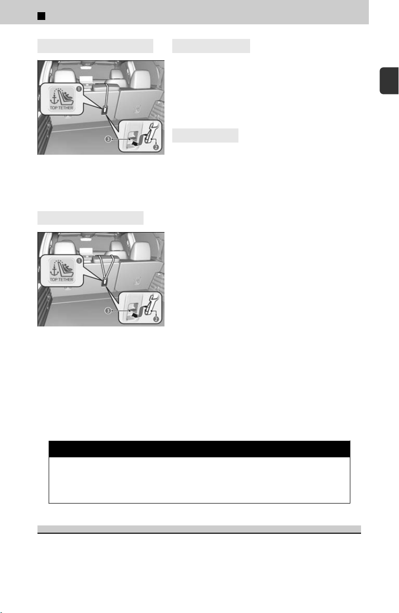
4
Straight Top Tether Type
a Top Tether Anchor Symbol
b Tether Strap Hook
c Anchor
4
Other Top Tether Type
a Top Tether Anchor Symbol
b Tether Strap Hook
c Anchor
4
Center position
[3] Lower the center head restraint to its lowest
position, then r
oute the tether strap over the
top of the head restraint.
Make sure the strap is not twisted.
4
All positions
[4] Secure the tether strap hook to the anchor.
[
5] Tighten the tether strap as instructed by the
child seat manufacturer.
[6] Make sure the child seat is firmly secured by
rocking it forward and back and side to side;
less than one inch of movement should
occur near the seat belt.
[7] Make sure any unused seat belt that a child
can reach is buckled, the lockable retractor
is activated, and the belt is fully retracted
and locked.
For your child’s safety, when using a child seat installed using the LATCH system,
mak
e sure that the child seat is properly secured to the vehicle.
A child seat that is not properly secured will not adequately protect a child in a crash
and may cause injury to the child or other vehicle occupants.
3 WARNING
Never attach two child seats to the same anchor. In a collision, one anchor
may not be s
trong enough to hold two child seat attachments and may
break, causing serious injury or death.
Installing a Child Seat with a Lap/Shoulder Seat Belt
A child seat can be installed with a lap/shoulder belt in any rear seat or, if absolutely
nec
essary, the front passenger seat.
1
Before Driving > Check Before Driving
25
1
Before Driving
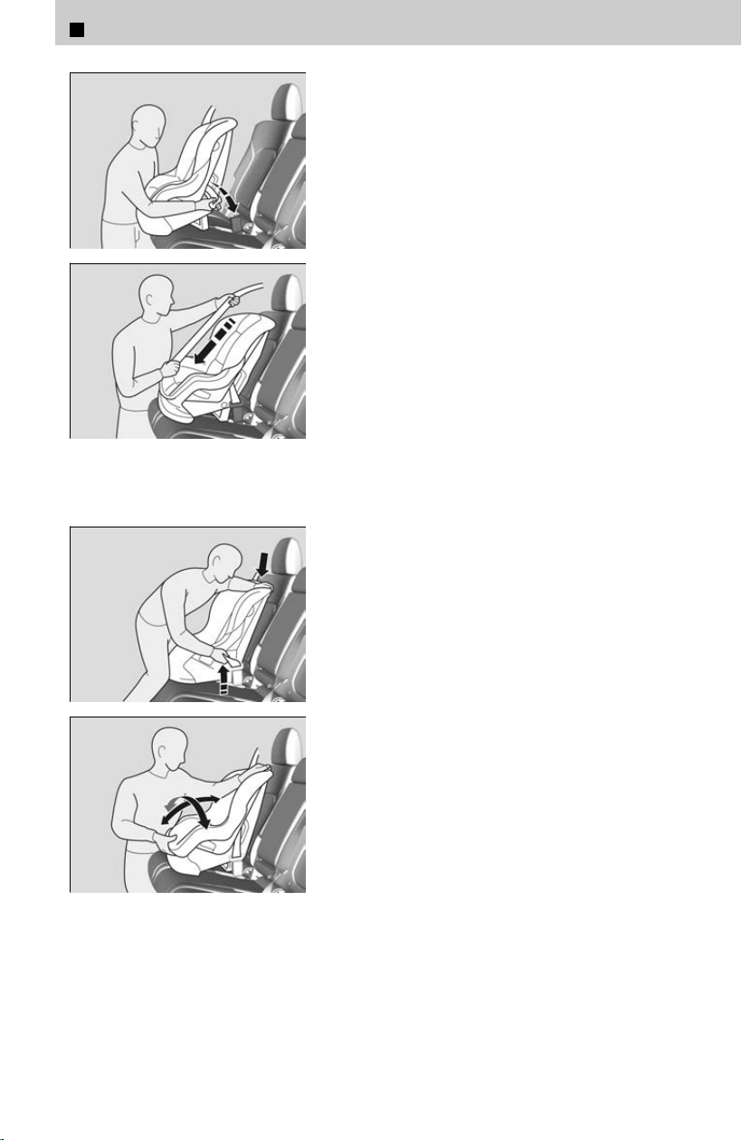
[1] Place the child seat on the vehicle seat.
[2] Route the seat belt through the child seat
according to the seat manufacturer’s
instructions, and insert the latch plate into
the buckle.
≫
Insert the latch plate fully until it clicks.
[3] Slowly pull the shoulder part of the belt all
the way out until it stops. This activates the
lockable retractor.
[4] Let the seat belt retract a few inches and
check that the retractor has switched modes
by pulling on the webbing. It should not pull
out again until it is reset by removing the
latch plate from the buckle.
≫
If you are able to pull the shoulder belt out, the
lockable retractor is not activated. Slowly pull
the seat belt all the way out, and repeat steps 3
– 4.
[5] Grab the shoulder part of the seat belt near
the buckle, and pull up to remove any slack
from the belt.
≫
Push the child seat firmly into the vehicle seat
while tightening the vehicle seat belt to remove
excess slack.
[6] Make sure the child seat is firmly secured by
rocking it forward and back and side to side;
less than one inch of movement should
occur near the seat belt.
[7] Make sure any unused seat belt that a child
can reach is buckled, the lockable retractor
is activated, and the belt is fully retracted
and locked.
A child seat that is not properly secured will not adequately protect a child in a crash
and may cause injur
y to the child or other vehicle occupants.
To deactivate a lockable retractor, release the buckle and allow the seat belt to wind
up all the way.
1
Before Driving > Check Before Driving
26
Adding Security with a Tether
a Top Tether Anchor Symbol
b Tether Anchor Points
A tether anchor point is provided behind each
r
ear seating position.
If you have a child seat that comes with a tether
but can be installed with a seat belt, the tether
may be used for additional security.
If you have a child seat that comes with a tether,
consult the child seat owner's manual for
additional instructions on tether usage.
Always use a tether for forward-facing child seats whether using the seat belt or
lo
wer anchors.
Using an outer anchor
4
Straight Top Tether Type
a Tether Strap Hook
b Anchor
4
Straight Top Tether Type
[1] Raise the outer head restraint to its highest
position, then r
oute the tether strap through
the head restraint legs. Make sure the strap
is not twisted.
4
Other Top Tether Type
a Tether Strap Hook
b Anchor
4
Other Top Tether Type
[1] Raise the outer head restraint to its highest
position, then r
oute the tether strap outside
the head restraint legs. Make sure the strap
is not twisted.
4
All types
[2] Secure the tether strap hook to the anchor.
[
3] Tighten the tether strap as instructed by the
child seat manufacturer.
1
Before Driving > Check Before Driving
27
1
Before Driving
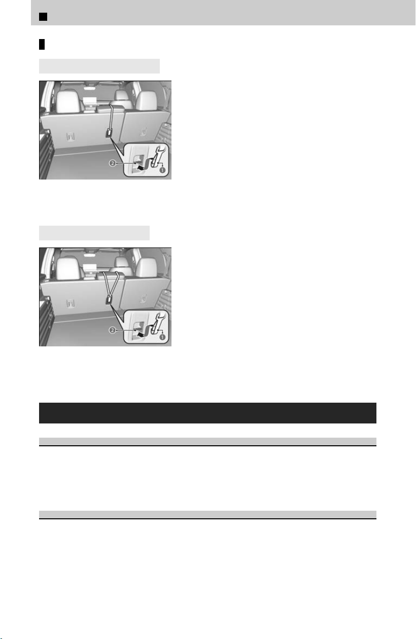
Using the center anchor
4
Straight Top Tether Type
a Tether Strap Hook
b Anchor
4
Other Top Tether Type
a Tether Strap Hook
b Anchor
[1] Lower the center head restraint to its lowest
position.
[
2] Route the tether strap over the top of the
head restraint. Make sure the strap is not
twisted.
[3] Secure the tether strap hook to the anchor.
[4] Tighten the tether strap as instructed by the
child seat manufacturer.
Safety of Larger Children
Protecting Larger Children
The following pages give instructions on how to check proper seat belt fit
, what kind
of booster seat to use if one is needed, and important precautions for a child who
must sit in front.
Checking Seat Belt Fit
When a child is too big for a child seat, secure the child in a rear seat using the lap/
shoulder seat bel
t. Have the child sit upright and all the way back, then answer the
following questions.
1
Before Driving > Check Before Driving
28
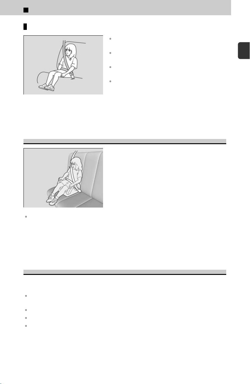
Checklist
Do the child’s knees bend comfortably over the edge
of the seat?
Does the shoulder belt cross between the child’s
neck and arm?
Is the lap part of the seat belt as low as possible,
touching the child’s thighs?
Will the child be able to stay seated like this for the
whole trip?
If you answer yes to all these questions, the child is ready to wear the lap/shoulder
seat bel
t correctly. If you answer no to any question, the child needs to ride on a
booster seat until the seat belt fits properly without a booster seat.
Booster Seats
If a lap/shoulder seat belt cannot be used
properly, position the child in a booster seat in the
rear seat. For the child’s safety, check that the
child meets the booster seat manufacturer’s
recommendations.
When installing a booster seat, make sure to read the instructions that came with it, and
install the seat accordingly. There are high- and low-type booster seats. Choose a booster
seat that allows the child to wear the seat belt correctly.
Some U.S. states and Canadian provinces and territories require children to use a
boos
ter seat until they reach a given age or weight (e.g., 6 years or 60 lbs). Be sure to
check current laws in the state, province, or territory where you intend to drive.
Protecting Larger Children - Final Checks
Your vehicle has a rear seat where children can be properly restrained. If you ever
hav
e to carry a group of children, and a child must ride in front:
Make sure you read and fully understand the instructions and safety information in this
manual.
Move the front passenger seat as far back as possible.
Have the child sit upright and well back in the seat.
Check that the seat belt is properly positioned so that the child is secure in the seat.
1
Before Driving > Check Before Driving
29
1
Before Driving

Monitoring child passengers
We strongly recommend that you keep an eye on child passengers. Even older,
mor
e mature children sometimes need to be reminded to fasten their seat belts
and sit up properly.
3 WARNING
Allowing a child age 12 or under to sit in front can result in injury or death if
the pas
senger’s front airbag inflates.
If a larger child must ride in front, move the vehicle seat as far to the rear as
possible, have the child sit up properly and wear the seat belt properly, and
use a booster seat if needed.
Exhaust Gas Hazard
Carbon Monoxide Gas
The engine exhaust from this vehicle contains carbon monoxide, a colorless, odorless,
and highl
y toxic gas. As long as you properly maintain your vehicle, carbon monoxide
gas will not get into the interior.
Have the exhaust system inspected for leaks whenever
The exhaust system is making an unusual noise.
The exhaust system may have been damaged.
The vehicle is raised for an oil change.
When you operate a vehicle with the tailgate open, airflow can pull exhaust gas into
the int
erior and create a hazardous condition. If you must drive with the tailgate
open, open all the windows and set the climate control system as shown below.
[1] Select the fresh air mode.
[
2] Select the mode.
[3] Set the fan speed to high.
[4] Set the temperature control to a comfortable setting.
Adjust the climate control system in the same manner if you sit in your parked
v
ehicle with the engine running.
3 WARNING
Carbon monoxide gas is toxic.
Br
eathing it can cause unconsciousness and even kill you.
Avoid any enclosed areas or activities that expose you to carbon monoxide.
1
Before Driving > Check Before Driving
30
!
Do not run the engine with the garage door closed.
An enclosed ar
ea such as a garage can quickly fill up with carbon monoxide
gas. Even when the garage door is open, drive out of the garage immediately
after starting the engine.
Modifications and Accessories
Modifications
Do not modify your vehicle in a manner that may affect its handling, stability, or reliability, or
install non-Genuine Honda parts or accessories that may have a similar effect.
Even minor modifications to vehicle systems can affect overall vehicle performance.
Always make sure all equipment is properly installed and maintained, and do not make any
modification to your vehicle or its systems that might cause your vehicle to no longer meet
federal, state, province, territory, and local regulations.
The on-board diagnostic port (OBD-II/SAE J1962 connector) installed on this vehicle is
intended to be used with automobile system diagnostic devices or with other devices that
Honda has approved. Use of any other type of device may adversely affect the vehicle’s
electronic systems or allow them to be compromised, possibly resulting in a system
malfunction, drained 12-volt battery, or other unexpected problems.
Do not modify or attempt to repair any of the electrical components.
3 WARNING
Improper accessories or modifications can aff
ect your vehicle’s handling,
stability, and performance, and cause a crash in which you can be seriously
hurt or killed.
Follow all instructions in this owner’s manual regarding accessories and
modifications.
!
Honda Genuine Accessories are recommended to ensure proper
oper
ation of your vehicle.
Accessories
When installing accessories, check the following:
Do not install accessories on the windshield. They can obstruct your view and delay your
reaction to driving conditions.
Do not install any items other than Honda Genuine Accessories designated for your vehicle
over areas containing airbags.
Items other than Honda Genuine Accessories designated for your vehicle installed in these
areas may interfere with proper operation of the vehicle’s airbags or may be propelled into
you or another occupant if the airbags deploy.
1
Before Driving > Check Before Driving
31
1
Before Driving

Be sure electronic accessories do not overload electrical circuits or interfere with proper
operation of your vehicle.
Checking Fuses
u
P.402
Before installing any electronic accessory, have the installer contact a dealer for assistance. If
possible, have a dealer inspect the final installation.
If any Honda Genuine Accessories become inoperable, refer to the separate
ac
cessory owner’s manual (if applicable) or consult a dealer for assistance to
troubleshoot the potential faulty condition.
About Your Airbags
Your vehicle is equipped with four types of airbags:
Front airbags: Airbags in front of the driver’s and front passenger’s seats.
Knee airbags: Airbags under the steering column and under the glove box.
Side airbags: Airbags in the driver’s and front passenger’s seat-backs.
Side curtain airbags: Airbags above the side windows.
Each is discussed in the following pages.
The airbags can inflate whenever the power mode is ON.
After an airbag inflates in a crash, you may see a small amount of smoke. This is from
the c
ombustion process of the inflator material and is not harmful. People with
respiratory problems may experience some temporary discomfort. If this occurs, get
out of the vehicle as soon as it is safe to do so.
1
Before Driving > Check Before Driving
32
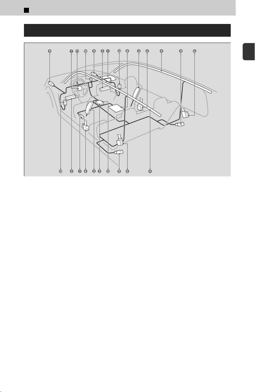
Airbag System Components
The front, driver’s knee, front passenger’s knee, side, and side curtain airbags are
deployed according to the direction and severity of impact. Both side curtain airbags
are deployed in a rollover. The airbag system includes:
a T
wo SRS (Supplemental Restraint System) front airbags. The driver’s airbag is
stored in the center of the steering wheel; the front passenger’s airbag is stored in
the dashboard. Both are marked SRS AIRBAG.
b Two knee airbags. The driver’s knee airbag is stored under the steering column;
the front passenger’s knee airbag is stored under the glove box. Both are marked
SRS AIRBAG.
c Two side airbags. One for the driver and one for the front passenger. The
airbags are stored in the outer edges of the seat-backs. Both are marked SIDE
AIRBAG.
d Two side curtain airbags, one for each side of the vehicle. The airbags are
stored in the ceiling, above the side windows. The front and rear pillars are marked
SIDE CURTAIN AIRBAG.
e An electronic control unit that, when the power mode is ON, continually
monitors information about the various impact sensors, seat and buckle sensors,
rollover sensor, airbag activators, seat belt tensioners, and other vehicle
information. During a crash event, the unit can record such information.
f Seat belt tensioners for the front seats and outer rear seats.
g Driver’s seat position sensor. This sensor detects the driver’s seat slide position
to help determine the optimal deployment of the driver’s airbag.
1
Before Driving > Check Before Driving
33
1
Before Driving

h Weight sensors in the front passenger’s seat. The sensors are used for
occupant classification to activate or deactivate the front passenger’s airbag.
i Impact sensors that can detect a moderate-to-severe front or side impact.
j An indicator on the dashboard that alerts you that the front passenger’s front
airbag has been turned off.
k An indicator on the instrument panel that alerts you to a possible problem with
your airbag system or seat belt tensioners.
l A rollover sensor that can detect if your vehicle is about to roll over and signal
the control unit to deploy both side curtain airbags.
m Pressure sensors that can detect a moderate-to-severe side impact.
Important Facts About Your Airbags
Airbags can pose serious hazards. To do their job, airbags must inflate with
tr
emendous force. So, while airbags help save lives, they can cause burns, bruises,
and other minor injuries, sometimes even fatal ones if occupants are not wearing
their seat belts properly and sitting correctly.
What you should do: Always wear your seat belt properly and sit upright and as far
back from the steering wheel as possible while allowing full control of the vehicle. A
front passenger should move their seat as far back from the dashboard as possible.
Remember, however, that no safety system can prevent all injuries or deaths that can
occur in a severe crash, even when seat belts are properly worn and the airbags
deploy.
Do not place hard or sharp objects between yourself and a front airbag. Carrying
hard or sharp objects on your lap, or driving with a pipe or other sharp object in your
mouth, can result in injuries if your front airbag inflates.
Do not attach or place objects on the front, driver’s knee, and front passenger’s
knee airbag covers. Objects on the covers marked SRS AIRBAG could interfere with
the proper operation of the airbags or be propelled inside the vehicle and hurt
someone if the airbags inflate.
Do not attempt to deactivate your airbags. Together, airbags and seat belts provide
the best protection.
When driving, keep hands and arms out of the deployment path of the front airbag by
holding each side of the steering wheel. Do not cross an arm over the airbag cover.
Front Airbags (SRS)
SRS (Supplemental R
estraint System) indicates that the airbags are designed to
supplement seat belts not replace them. Seat belts are the occupant primary
restraint system.
The front SRS airbags inflate in a moderate-to-severe frontal collision to help protect
the head and chest of the driver and/or front passenger.
1
Before Driving > Check Before Driving
34
During a frontal crash severe enough to cause one or both front airbags to deploy, the
airbags can inflate at different rates, depending on the severity of the crash, whether
or not the seat belts are latched, and/or other factors. Frontal airbags are designed to
supplement the seat belts to help reduce the likelihood of head and chest injuries in
frontal crashes.
Housing Locations
The front airbags are housed in the center of the steering wheel for the driver, and in
the dashboar
d for the front passenger. Both airbags are marked SRS AIRBAG.
Operation
Front airbags are designed to inflate during moderate-to-severe frontal collisions.
When the v
ehicle decelerates suddenly, the sensors send information to the control
unit which signals one or both front airbags to inflate.
A frontal collision can be either head-on or angled between two vehicles, or when a
vehicle crashes into a stationary object, such as a concrete wall.
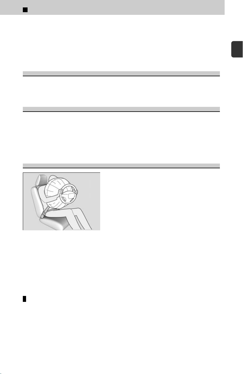
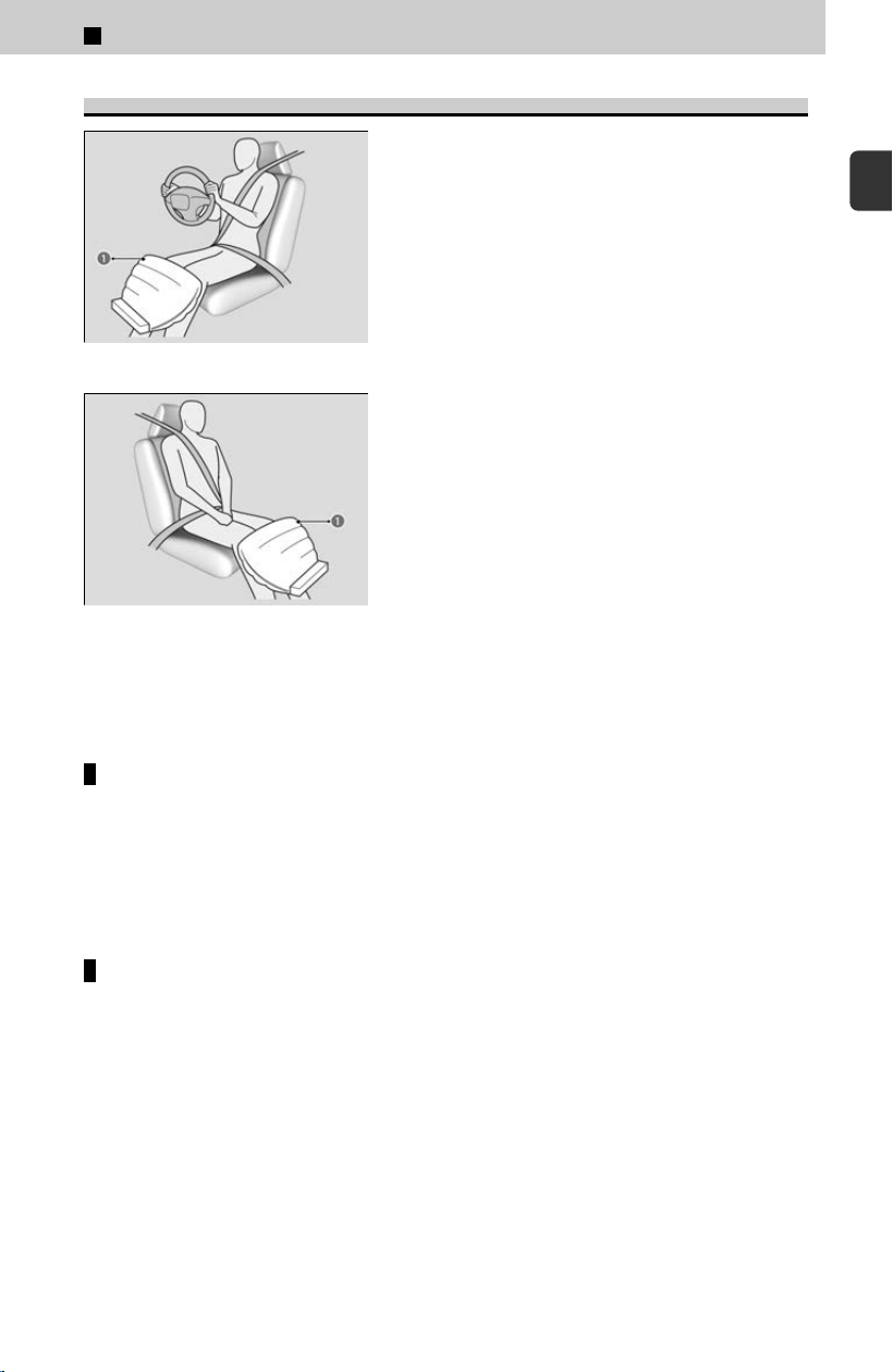
How the Front Airbags Work
While your seat belt restrains your torso, the front
airbag provides supplemental protection for your
head and chest.
The front airbags deflate immediately so that they
won’t interfere with the driver’s visibility or the
ability to steer or operate other controls.
The total time for inflation and deflation is so fast that most occupants are not aware
that the airbags deplo
yed until they see them lying in front of them.
Although the driver’s and front passenger’s airbags normally inflate within a split
second of each other, it is possible for only one airbag to deploy. This can happen if
the severity of a collision is at the margin, or threshold that determines whether or not
the airbags will deploy. In such cases, the seat belt will provide sufficient protection,
and the supplemental protection offered by the airbag would be minimal.
When front airbags should not deploy
Minor frontal crashes: Front airbags were designed to supplement seat belts and
help sav
e lives, not to prevent minor scrapes or even broken bones that might occur
during a less than moderate-to-severe frontal crash.
1
Before Driving > Check Before Driving
35
1
Before Driving

Side impacts: Front airbags can provide protection when a sudden deceleration
causes a driver or front passenger to move toward the front of the vehicle.Side
airbags and side curtain airbags have been specifically designed to help reduce the
severity of injuries that can occur during a moderate-to-severe side impact which
can cause the driver or passenger to move toward the side of the vehicle.
Rear impacts: Head restraints and seat belts are your best protection during a rear
impact. Front airbags cannot provide any significant protection and are not
designed to deploy in such collisions.
Rollovers: In a rollover, your best form of protection is a seat belt or, if your vehicle
is equipped with a rollover sensor, both a seat belt and a side curtain airbag. Front
airbags, however, are not designed to deploy in a rollover as they would provide
little, if any, protection.
When front airbags deploy with little or no visible damage
Because the airbag system senses sudden deceleration, a strong impact to the
v
ehicle framework or suspension might cause one or more of the airbags to deploy.
Examples include running into a curb, the edge of a hole, or other low fixed object
that causes a sudden deceleration in the vehicle chassis. Since the impact is
underneath the vehicle, damage may not be readily apparent.
When front airbags may not deploy, even though exterior damage
appears severe
Since crushable body parts absorb crash energy during an impact, the amount of
visible damag
e does not always indicate proper airbag operation. In fact, some
collisions can result in severe damage but no airbag deployment because the
airbags would not have been needed or would not have provided protection even if
they had deployed.
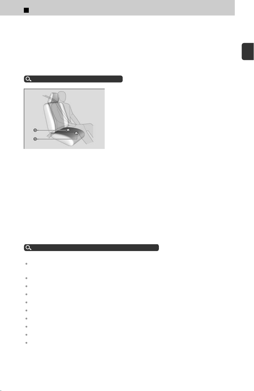
Advanced Airbags
The airbags have advanced features to help reduce the likelihood of airbag related
injuries t
o smaller occupants.
a Driver’s Seat Position Sensor
The driver’s advanced airbag system includes a seat position sensor.
1
Before Driving > Check Before Driving
36
Based on information from this sensor and the severity of the impact, the advanced
airbag system determines the optimal deployment of the driver’s airbag.
The front passenger’s advanced airbag system has weight sensors. The sensors are
used for occupant classification to activate or deactivate the front passenger’s airbag.
For adult size occupants, the system will automatically activate the front passenger’s
airbag. If a small adult sits in the front passenger seat and the system does not
recognize him/her as an adult, see below.
Passenger Airbag Off Indicator
u
P.43
a Passenger’s Seat Weight
Sensors
We advise against allowing a child age 12 or under to ride in the front passenger’s
seat
. However, if you do allow a small child or infant to ride in the front passenger’s
seat, the system is designed to automatically deactivate the front passenger’s airbag.
Do not let a small child or infant ride in the front passenger’s seat if the airbag does
not automatically deactivate.
If there is a problem with the driver’s seat position sensor or the passenger’s seat
weight sensors, the SRS indicator will come on, and in the event of a crash, the airbag
will deploy (regardless of the driver’s seating position or passenger’s occupant
classification) with a force corresponding to the severity of the impact.
Supplemental Restraint System (SRS) Indicator
u
P.43
For the advanced front airbags to work properly, c
onfirm that:
The occupant is sitting in an upright position wearing the seat belt properly and the seat-back
is not excessively reclined.
The occupant is not leaning against the door or center console.
The occupant’s feet are placed on the floor in front of them.
There are no objects hanging from the front passenger’s seat.
Only small, lightweight objects are in the seat-back pocket.
The steering wheel and passenger’s side dashboard are not obstructed by any object.
No liquid has been spilled on or under the seat.
There is no child seat or other object pressing against the rear of the seat or seat-back.
There is no rear passenger pushing or pulling on the back of the front passenger’s seat.
There are no objects placed under or beside the front passenger’s seat. Improperly
positioned objects can interfere with the advanced airbag sensors.
1
Before Driving > Check Before Driving
37
1
Before Driving

The head restraint is not contacting the roof.
Passenger Airbag Off Indicator
u
P.43
The floor mat behind the front passenger’s seat is set in the correct position evenly on the
floor. An improperly placed mat can interfere with the advanced airbag sensors.
Interior Care
u
P.379
Knee Airbags
The knee SRS airbags inflate in a moderate-to-severe frontal collision to help keep
the driv
er and/or front passenger in the proper position and to help maximize the
benefit provided by the vehicle’s other safety features.
SRS (Supplemental Restraint System) indicates that the airbag is designed to
supplement seat belts, not replace them. Seat belts are the occupant’s primary
restraint system.
Do not attach accessories on or near a knee airbag as they can interfere with the
proper operation of the airbag, or even hurt someone if the airbag inflates.
The driver and front passenger should not store any items under the seat or behind
their feet. The items can interfere with proper airbag deployment in the event of a
moderate to severe frontal collision and may result in inadequate protection.
Housing Locations
The knee airbag for the driver and the one for the front passenger are housed under
the s
teering column and the glove box respectively.
Both are marked SRS AIRBAG.
1
Before Driving > Check Before Driving
38
Operation
a Knee Airbag
a Knee Airbag
The driver’s and front passenger’s knee airbag
deplo
y at the same time as the driver’s and front
passenger’s airbag respectively.
Even if the collision is not severe enough to deploy the front airbag, the knee airbag
may inflat
e alone.
When knee airbags deploy with little or no visible damage
Because the airbag system senses sudden deceleration, a strong impact to the
v
ehicle framework or suspension might cause one or more of the airbags to deploy.
Examples include running into a curb, the edge of a hole, or other low fixed objects
that cause a sudden deceleration in the vehicle chassis. Since the impact is
underneath the vehicle, damage may not be readily apparent.
When knee airbags may not deploy, even though exterior damage
appears severe
Since crushable body parts absorb crash energy during an impact, the amount of
visible damag
e does not always indicate proper airbag operation. In fact, some
collisions can result in severe damage but no airbag deployment because the
airbags would not have been needed or would not have provided protection even if
they had deployed.
1
Before Driving > Check Before Driving
39
1
Before Driving
Side Airbags
The side airbags help protect the torso and pelvis of the driver or a front passenger
during a moder
ate-to-severe side impact.
!
Do not cover or replace the front seat-back covers without consulting a
dealer
.
Improperly replacing or covering front seat-back covers can prevent your side
airbags from properly deploying during a side impact.
!
Make sure you and your front seat passenger always sit upright.
L
eaning into the path of a side airbag can prevent the airbag from
deploying properly and increases your risk of serious injury.
!
Do not attach accessories on or near the side airbags. They can
int
erfere with the proper operation of the airbags, or hurt someone if
an airbag inflates.
!
Side airbag deployment is controlled by a pressure sensor inside each
fr
ont door. Damage or changes to the inside or outside of the doors
may negatively affect side airbag deployment. Contact an authorized
dealer before changing or repairing a front door.
Housing Locations
The side airbags are housed in the outside edge of the driver’s and passenger’s seat-
back
s.
Both are marked SIDE AIRBAG.
1
Before Driving > Check Before Driving
40
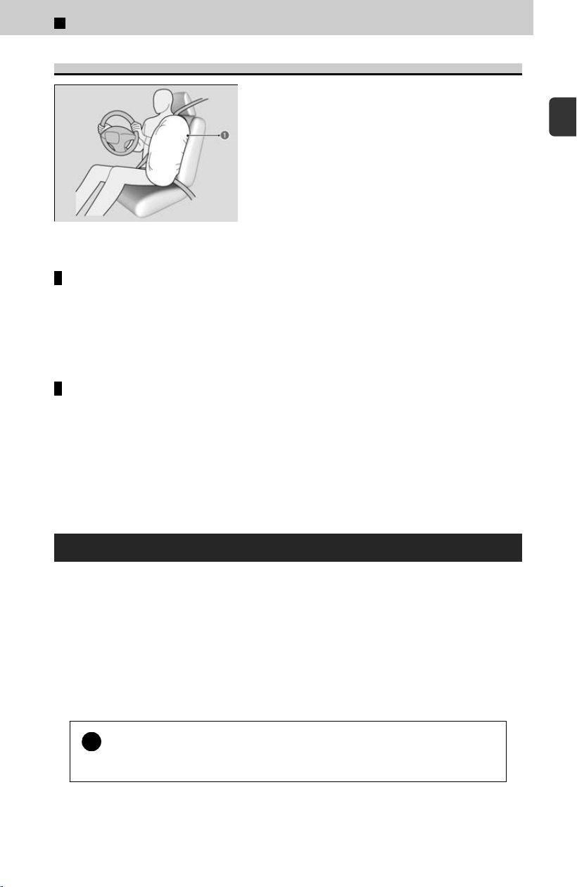
Operation
a Side Airbag
When the sensors detect a moderate-to-severe
side impact
, the control unit signals the side
airbag on the impact side to immediately inflate.
When a side airbag deploys with little or no visible damage
Because the airbag system senses sudden acceleration, a strong impact to the side
o
f the vehicle’s framework can cause a side airbag to deploy. In such cases, there
may be little or no damage, but the side impact sensors detected a severe enough
impact to deploy the airbag.
When a side airbag may not deploy, even though visible damage
appears severe
It is possible for a side airbag not to deploy during an impact that results in
appar
ently severe damage. This can occur when the point of impact was toward the
far front or rear of the vehicle, or when the vehicle’s crushable body parts absorbed
most of the crash energy. In either case, the side airbag would not have been
needed nor provided protection even if it had deployed.
Side Curtain Airbags
The side curtain airbags help protect the heads of the driver and passengers in the
out
er seating positions during a moderate-to-severe side impact. The side curtain
airbags equipped in this vehicle are also designed to help reduce the likelihood of
partial and complete ejection of vehicle occupants through side windows in crashes,
particularly rollover crashes.
If the SRS control unit senses that your vehicle is about to rollover, it immediately
deploys both side curtain airbags and activates the seat belt tensioners for the front
seats and outer rear seats.
!
Do not attach any objects to the side windows or roof pillars as they
can int
erfere with the proper operation of the side curtain airbags.
1
Before Driving > Check Before Driving
41
1
Before Driving
!
To get the best protection from the side curtain airbags, occupants
should w
ear their seat belts properly and sit upright and well back in
their seats.
Housing Locations
The side curtain airbags are located in the ceiling above the side windows on both
sides o
f the vehicle.
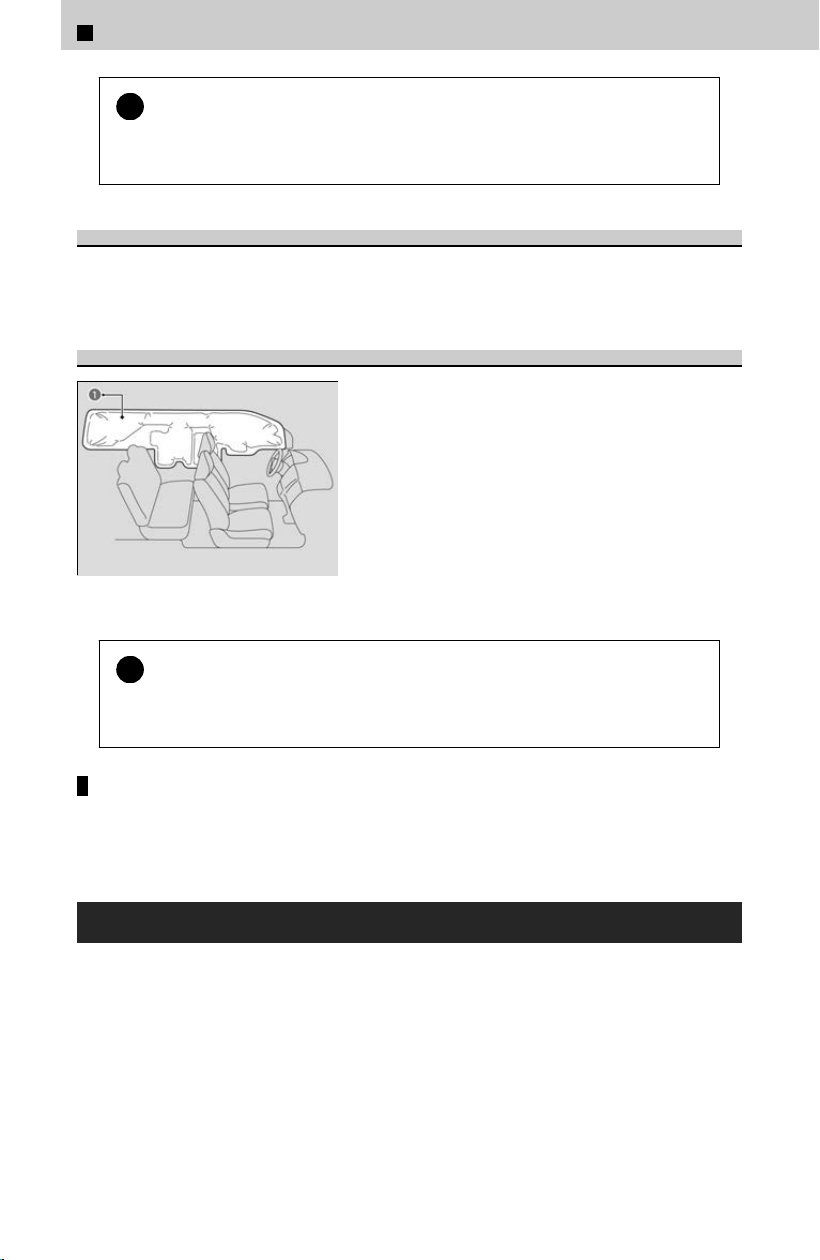
Operation
a Side Curtain Airbag
The side curtain airbag is designed to deploy in a
r
ollover or a moderate-to-severe side impact.
!
If the impact is on the passenger’s side, the passenger’s side curtain
airbag deplo
ys even if there are no occupants on that side of the
vehicle.
When side curtain airbags deploy in a frontal collision
One or both side curtain airbags may also inflate in a moderate-to-severe angled
fr
ontal collision.
Airbag System Indicators
If a problem occurs in the airbag system, the SRS indicator will come on and a
mes
sage appears on the driver information interface.
1
Before Driving > Check Before Driving
42
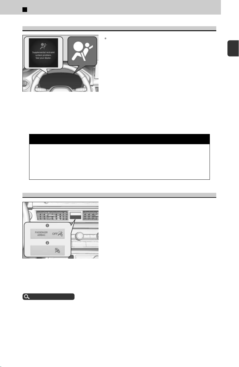
Supplemental Restraint System (SRS) Indicator
When the power mode is set to ON
The indicator comes on for a few seconds, then
g
oes off. This tells you the system is working
properly.
If the indicator comes on at any other time, or does not come on at all, have the
s
ystem checked by a dealer as soon as possible.
If you don’t, your airbags and seat belt tensioners may not work properly when they
are needed.
3 WARNING
Ignoring the SRS indicator can result in serious injury or death if the airbag
s
ystems or tensioners do not work properly.
Have your vehicle checked by a dealer as soon as possible if the SRS
indicator alerts you to a possible problem.
Passenger Airbag Off Indicator
a U.S.
b Canada
When the passenger airbag off indicator
c
omes on
The indicator comes on to alert you that the
passenger’s airbag has been turned off.
This occurs if the seat is empty or when the
weight sensors determine that a small child or
infant is on the passenger seat.
Children age 12 or under should always ride properly restrained in a back seat.
Child Safety
u
P.19
If the indicator is on, in the event of a crash the passenger’s airbag will not deploy.
The pas
senger’s knee airbag will not deploy, either.
When you set the power mode to ON, the indicator comes on and goes off a few
seconds later to indicate that system checks are being performed. After that, the
indicator comes on or off depending on the passenger’s occupant classification.
To ensure the passenger is detected properly, confirm that:
1
Before Driving > Check Before Driving
43
1
Before Driving

The occupant is sitting in an upright position wearing the seat belt properly and the seat-back
is not excessively reclined.
The occupant is not leaning against the door or center console.
The occupant’s feet are placed on the floor in front of them.
There are no objects hanging from the front passenger’s seat.
Only small, lightweight objects are in the seat-back pocket.
No liquid has been spilled on or under the seat.
There is no child seat or other object pressing against the rear of the seat or seat-back.
There is no rear passenger pushing or pulling on the back of the front passenger’s seat.
There are no objects placed under or beside the front passenger’s seat. Improperly
positioned objects can interfere with the advanced airbag sensors.
The floor mat behind the front passenger’s seat is set in the correct position evenly on the
floor. An improperly placed mat can interfere with the advanced airbag sensors.
The head restraint is not contacting the roof.
The passenger airbag off indicator may come on and go off periodically if the total
w
eight on the seat is near the airbag cutoff threshold. For a small adult, depending on
physique and posture, the system may not recognize him/her as an adult and thus
deactivate the passenger’s airbag.
If this occurs, please confirm that the conditions set forth in the above bullet points
on the previous page are met.
If the above conditions are met and the indicator is still on, then with the transmission
in P , set the power mode to OFF and back to ON.
Have your vehicle checked by a dealer as soon as possible if:
All of the above conditions are met, and the indicator comes on with an adult seated in the
front passenger seat.
The seat is empty and the indicator is off.
The indicator does not come on and go off after setting the power mode to ON as described.
Do not allow an adult passenger to ride in the front seat when the indicator is on.
Airbag Care
You do not need to, and should not, perform any maintenance on or replace any
airbag s
ystem components yourself. However, you should have your vehicle inspected
by a dealer in the following situations:
When the airbags have deployed
If an airbag has inflated, the control unit and other related parts must be replaced.
Similarl
y, once an automatic seat belt tensioner has been activated, it must be
replaced.
1
Before Driving > Check Before Driving
44

!
We recommend against the use of salvaged airbag system
c
omponents, including the airbag, tensioners, sensors, and control
unit.
When the vehicle has been in a moderate-to-severe
collision
Even if the airbags did not inflate, have your dealer inspect the following: the driver’s
seat position sensor
, weight sensors in the passenger’s seat, seat belt tensioners for
the front seats and outer rear seats, and each seat belt that was worn during the
crash.
Do not remove or modify a front seat without consulting a
dealer
This would likely disable or affect the proper operation of the driver’s seat position
sensor or the w
eight sensors in the passenger’s seat. If it is necessary to remove or
modify a front seat to accommodate a person with disabilities, contact a Honda
dealer. For U.S. vehicles, contact American Honda Automobile Customer Service at
1-800-999-1009. For Canadian vehicles, contact Honda Canada Customer Relations
at 1-888-9-HONDA-9.
1
Before Driving > Check Before Driving
45
1
Before Driving
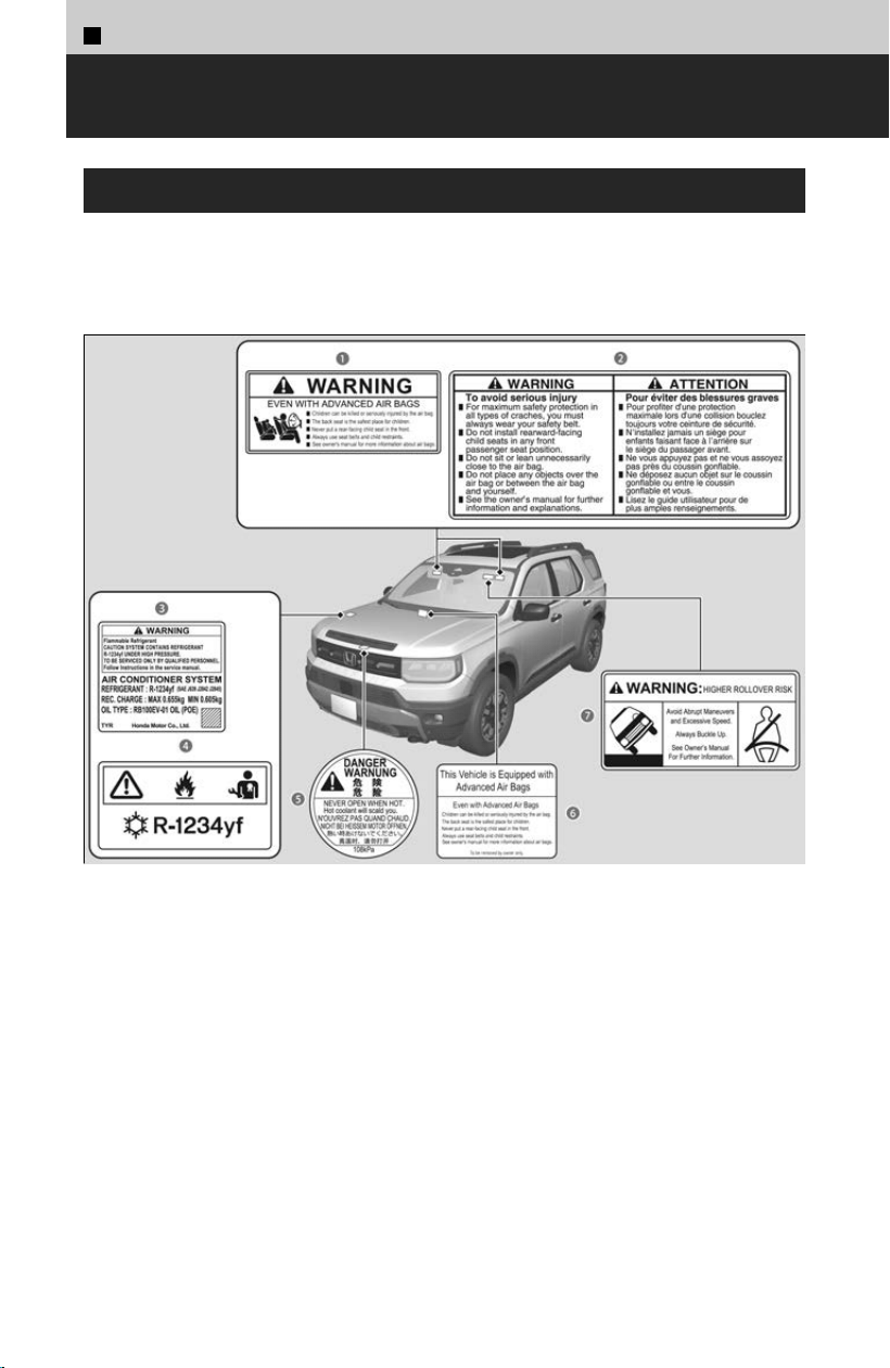
1
Before Driving >
Safety Labels
Label Locations
These labels are in the locations shown. They warn you of potential hazards that can
cause serious injur
y or death. Read these labels carefully.
If a label comes off or becomes hard to read (except for the U.S. dashboard label,
which may be removed by the owner), contact a dealer for a replacement.
a Sun Visor (U.S. models)
b Sun Visor (Canadian models)
c Air Conditioner Sy
stem (U.S. models)
d Air Conditioner Sy
stem (Canadian models)
e R
adiator Cap
f Dashboar
d (U.S. models only)
g Sun Visor (U
.S. models only)
46
1
Before Driving >
Key
Details on the Key
Use the keys to start and stop the engine, and lock and unlock all the doors, tailgate,
and fuel fil
l door.
You can remotely start the engine using the remote engine start.
Remote Engine Start
u
P.112
Low keyless remote signal strength
The vehicle transmits radio waves to locate the keyless remote to start the engine;
lock and unlock al
l the doors and the fuel fill door; and operate the power tailgate.
In the following cases, starting the engine, locking/unlocking the doors/fuel fill
door, or opening the power tailgate may be inhibited, or operation may be unstable:
Strong radio waves are being transmitted by nearby equipment.
You are carrying the keyless remote together with telecommunications equipment, laptop
computers, cell phones, or wireless devices.
A metallic object is touching or covering the keyless remote.
Battery life is about two years, but this varies depending on regularity of use.
Communication between the keyless remote and the vehicle consumes the keyless
r
emote’s battery.
!
Follow the advice below to prevent damage to the keys:
Do not leave the keys in direct sunlight, or in locations with high temperature
or high humidity.
Do not drop the keys or set heavy objects on them.
Keep the keys away from liquids, dust, and sand.
Do not take the keys apart except to replace the battery.
!
Do not leave the keyless remote in the vehicle when you get out. Carry
it with y
ou.
!
The battery is consumed whenever the keyless remote is receiving
s
trong radio waves. Avoid placing it near electrical appliances such as
televisions and personal computers.
47
1
Before Driving

Keyless Remote Reminder
When the power mode is in ON
If you remove the keyless remote from the vehicle and shut the door, a warning
indicat
or will display in the instrument panel, and warning buzzers will sound from
both inside and outside the vehicle.
When the power mode is in ACCESSORY
If you remove the keyless remote from the vehicle and shut the door, a warning
buzz
er will sound from outside the vehicle.
Do not put the keyless remote on the dashboard or in the glove box. It may cause the
warning buzzer to sound.
Under some other conditions that can prevent the vehicle from locating the keyless remote,
the warning buzzer may also sound even if the keyless remote is within the system’s
operational range.
If the keyless remote is taken out of the vehicle after the engine has been started, you can
no longer change the ENGINE START/STOP button mode or restart the engine. Always
make sure that the keyless remote is in your vehicle when you operate the ENGINE START/
STOP button.
Removing the keyless remote from the vehicle through a window does not activate the
warning buzzer.
Stopping the warning buzzer
When the keyless remote is within the system’s operational range and the driver’s
door is closed, the w
arning function cancels.
≫
If the alarm continues to sound, place the keyless remote in another location.
Immobilizer System
This system prevents a key that has not been pre-registered from starting the engine.
Pay attention to the following:
Do not allow objects that emit strong radio waves near the ENGINE START/STOP button.
Make sure the key is not covered by or touching a metal object.
Do not bring a key from another vehicle’s immobilizer system near the ENGINE START/STOP
button.
Do not put the key near magnetic items. Electronic devices, such as televisions and audio
systems, emit strong magnetic fields. Note that even a key chain can become magnetic.
Do not alter the system or add other devices to it.
Doing so may damage the system and make your vehicle inoperable.
1
Before Driving > Key
48
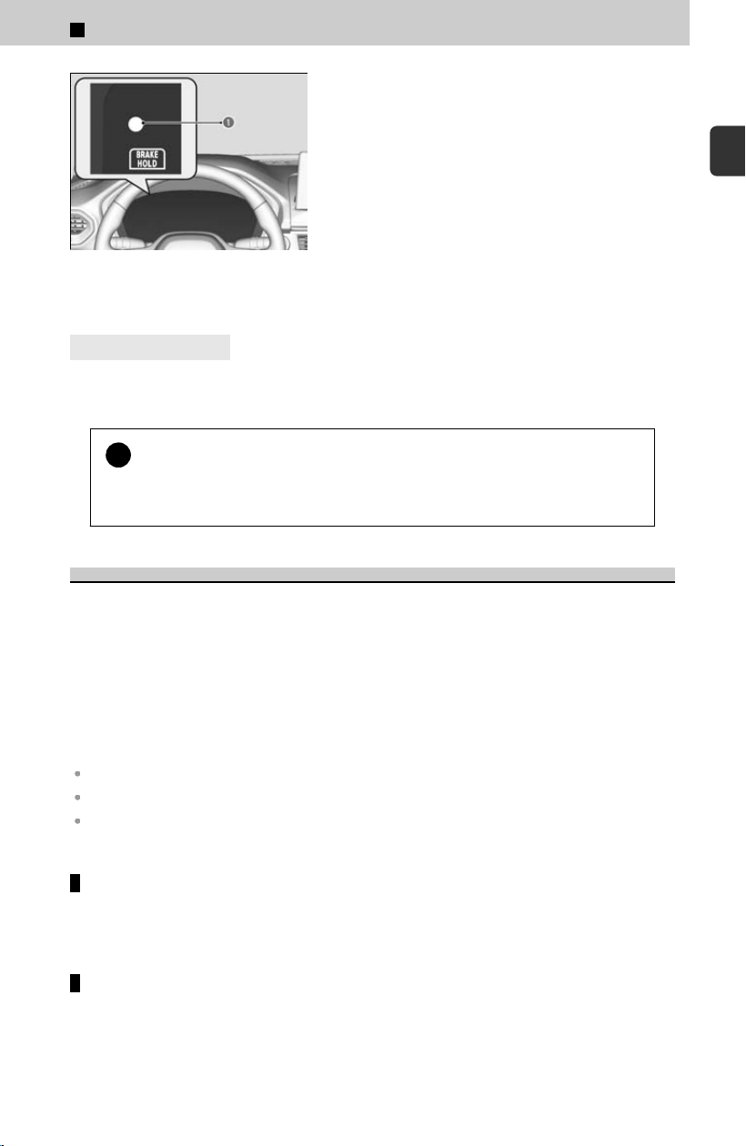
a Immobilizer System
Indicator
The immobilizer system indicator will blink in the
ins
trument panel if the immobilizer system
cannot recognize the key information when you
have pressed ENGINE START/STOP button.
4
Canadian models
Apply and hold the brake pedal before turning the vehicle on the firs
t time after the
12-volt battery has been disconnected.
!
Leaving the key in the vehicle can result in theft or accidental
mo
vement of the vehicle. Always take the key with you whenever you
leave the vehicle unattended.
Security System Alarm
The security system alarm activates when the tailgate, hood, or doors are forcibly
opened. The alarm does not activ
ate if the tailgate or doors are opened with the
remote transmitter or keyless access system.
Unlock the vehicle using the remote transmitter or keyless access system, or turn the
power mode to ON. The system, along with the horn and flashing lights, is
deactivated.
The security system alarm automatically sets when the following conditions have
been met.
The power mode is set to VEHICLE OFF.
The hood is closed.
All doors and the tailgate are locked from outside with the remote transmitter or keyless
access system.
When the security system alarm sets
The security system alarm indicator in the instrument panel blinks and the blinking
int
erval changes after about 15 seconds.
To cancel the security system alarm
The security system alarm is canceled when the vehicle is unlocked using the
r
emote transmitter or keyless access system, or the power mode is set to ON. The
security system alarm indicator goes off at the same time.
1
Before Driving > Key
49
1
Before Driving
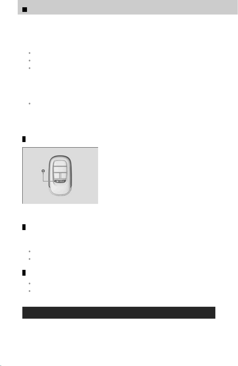
The security system alarm continues for a maximum of two minutes until the
security system alarm deactivates.
Do not set the security system alarm when someone is in the vehicle or a window is
open. The system can accidentally activate when:
Unlocking the door with the lock tab.
Opening the hood with the hood release.
Opening the tailgate with the power tailgate button on the dashboard.
If the 12-volt battery goes dead after you have set the security system alarm, the
securit
y alarm may sound once the 12-volt battery is recharged or replaced.
If this occurs, deactivate the security system alarm by unlocking a door using the
remote transmitter or keyless access system.
Do not alter the system or add other devices to it. Doing so may damage the system and
make your vehicle inoperable.
If you unlock a door with the built-in key while the security system is activated, the
alarm wil
l sound.
Panic mode
a Panic Button
The panic button on the remote transmitter
If you press the panic button for approximately one second, the following will occur
f
or about 30 seconds:
The horn sounds.
Some exterior lights flash.
Canceling panic mode
Press any button on the remote transmitter.
Set the power mode to ON.
Built-in Key
The built-in key can be used to unlock the doors when the keyless remote battery
bec
omes weak and the power door unlock operation is disabled.
1
Before Driving > Key
50
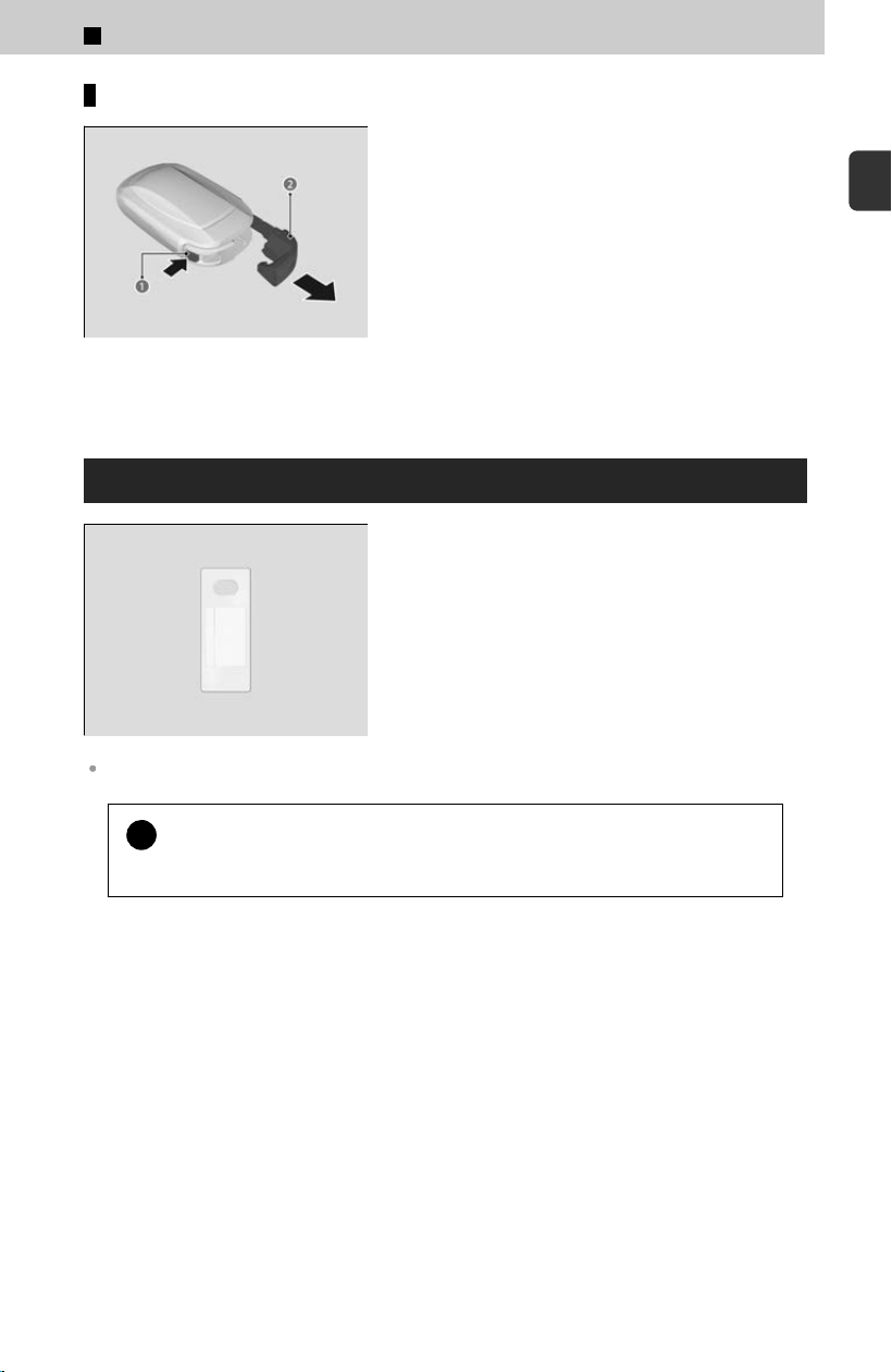
Removing the built-in key
a Release Button
b Built-in Key
To remove the built-in key, push the release
but
ton and then pull out the key. To reinstall the
built-in key, push the built-in key into the keyless
remote until it clicks.
Key Number Tag
Contains a number that you will need if you
purchase a replacement key.
If you lose your key and you cannot start the engine, contact a dealer.
!
Keep the key number tag separate from the key in a safe place outside
o
f your vehicle.
1
Before Driving > Key
51
1
Before Driving
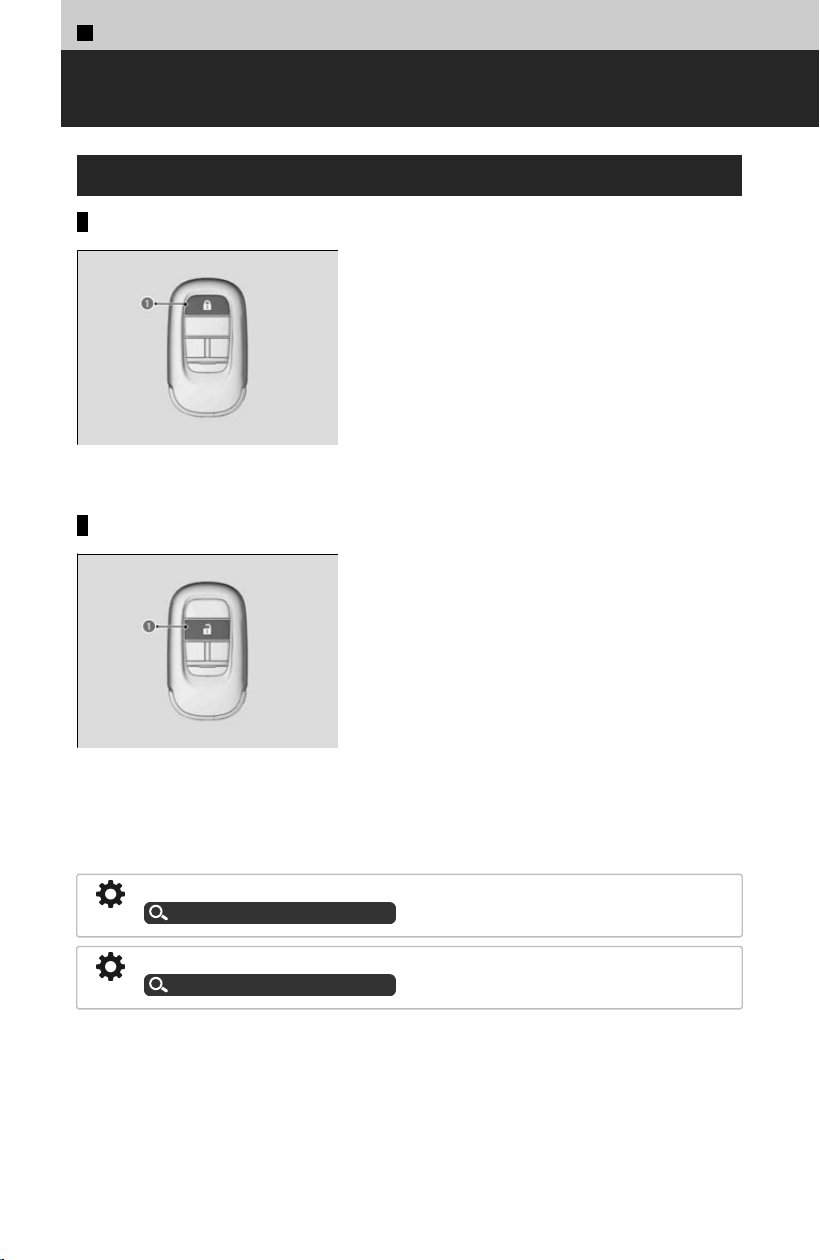
1
Before Driving >
Locking/Unlocking
Using the Remote Transmitter
Locking the doors and tailgate
a Lock Button
Press the lock button.
Once:
≫
Some exterior lights flash; all the doors, tailgate, and
fuel fill door lock; and the security system sets.
Twice (within fiv
e seconds after the first push):
≫
The beeper sounds and verifies the security system is
set.
Unlocking the doors and tailgate
a Unlock Button
Press the unlock button.
Once:
≫
Some exterior lights flash twice, and the driver’s door
and fuel fill door unlocks.
Twice:
≫
The remaining doors and tailgate unlock.
If you do not open a door or the tailgate within 30 seconds of unlocking the vehicle
with the r
emote transmitter, the doors and tailgate will automatically relock.
You can change the relock timer setting.
Customized Features
u
P.239
You can customize the door unlock mode setting.
Customized Features
u
P.239
52
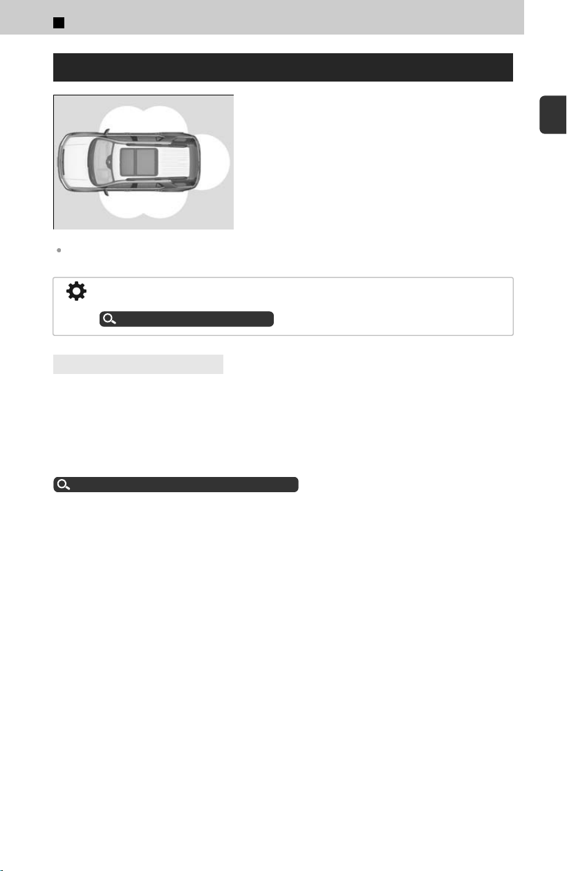
Using the Keyless Access System
When you carry the keyless remote, you can lock/
unlock the doors and fuel fill door, and open the
tailgate.
You can lock/unlock the doors, fuel fill door, and
tailgate within a radius of about 32 inches (80
cm) from the outside door handle or tailgate outer
handle.
The door may be unlocked if the door handle is covered with water in heavy rain or in a car
wash if the keyless remote is within range.
The light flash, beep, and door unlock mode settings can be customized using the
audio/information screen.
Customized Features
u
P.239
4
Models with puddle lights
When you go into the keyless access system working range with all the doors locked,
the puddle lights c
ome on for 30 seconds.
The lights do not come on if you have previously stayed within the range for more
than two minutes, or the doors have been locked for few days.
The feature activates again after you drive the vehicle, then lock the doors.
You can also unlock and open the power tailgate.
Opening/Closing the Power Tailgate
u
P.87
Please wipe off any residue such as car shampoo, groundwater, or anti-freeze in the
vicinit
y of the outside door handle, as there is a risk that the keyless access system
may not work properly.
1
Before Driving > Locking/Unlocking
53
1
Before Driving
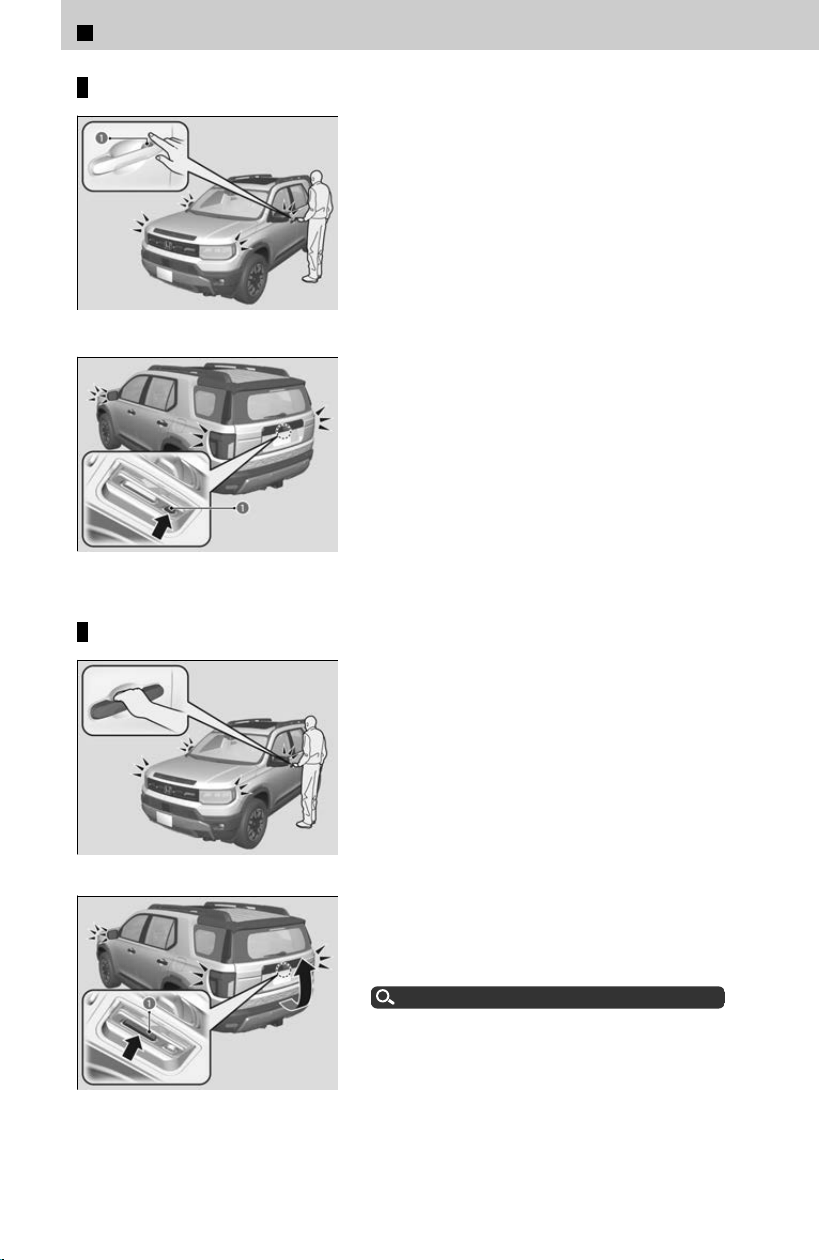
Locking the doors and tailgate
a Door Lock Sensor
a Lock Button
Touch the door lock sensor on the front or rear
*
doors
, or press the lock button on the tailgate.
≫
All the doors, fuel fill door, and tailgate lock, and the
security system sets.
≫
Some exterior lights flash once and the beeper
sounds once.
Unlocking the doors and tailgate
Grab the driver’s door handle:
≫
The driver’s door and fuel fill door unlock.
≫
Some exterior lights flash twice and the beeper
sounds twice.
Grab the front passenger’s door or rear
*
door
handle:
≫
All doors, tailgate, and fuel fill door unlock.
≫
Some exterior lights flash twice and the beeper
sounds twice.
a Outer Handle
Press and hold the tailgate outer handle:
≫
The tailgate unlocks.
≫
Some exterior lights flash twice and the beeper
sounds twice.
Opening/Closing the Power Tailgate
u
P.87
*: Not available on all models
1
Before Driving > Locking/Unlocking
54
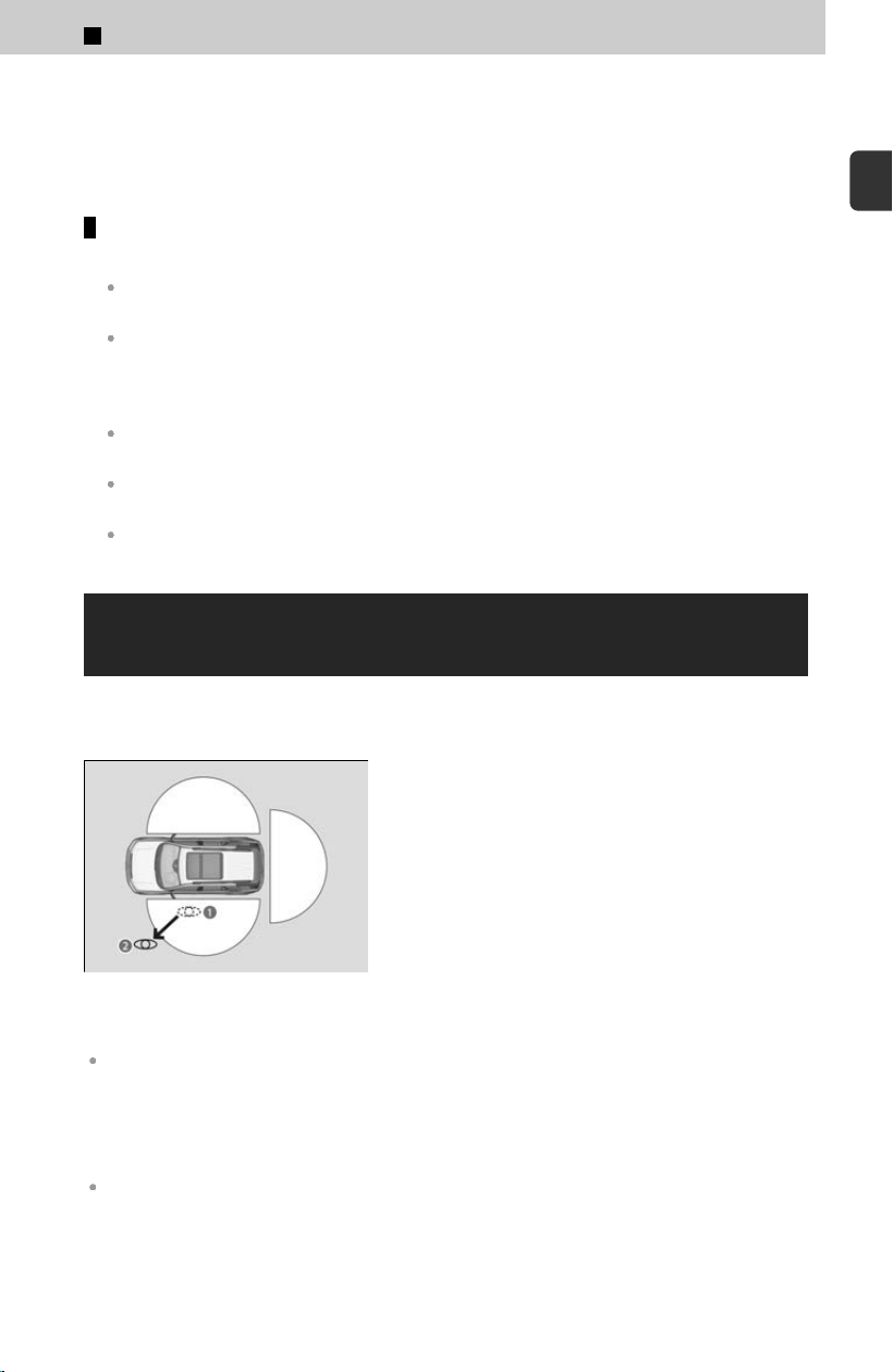
If you do not open a door or the tailgate within 30 seconds of unlocking the vehicle
with the keyless access system, the doors and tailgate will automatically relock.
You cannot lock or unlock doors using the keyless access system when the power
mode is set to any mode other than VEHICLE OFF.
Conditions under which you may not be able to lock/unlock the doors
and tailgate
If you grip a door handle or touch a door lock sensor wearing gloves, the door sensor may
be slow to respond or may not respond by unlocking or locking the doors.
After locking the door, you have up to two seconds during which you can pull the door
handle to confirm whether the door is locked. If you need to unlock the door immediately
after locking it, wait at least two seconds before gripping the handle, otherwise the door will
not unlock.
The door might not open if you pull it immediately after gripping the door handle. Grip the
handle again and confirm that the door is unlocked before pulling the handle.
Even within the 32 inches (80 cm) radius, you may not be able to lock/unlock the doors and
tailgate with the keyless remote if it is above or below the outside handle.
The keyless remote may not operate if it is too close to the door, door glass, or tailgate.
Locking the Doors and Tailgate (Walk Away
Auto Lock®)
When you walk away from the vehicle with all doors and tailgate closed while carrying
the k
eyless remote, the doors, tailgate, and fuel fill door will automatically lock.
[1] While within about 5 feet (1.5 m) radius of
the v
ehicle.
≫
The beeper sounds; the auto lock function will
be activated.
[2] Carry the keyless remote beyond about 5
f
eet (1.5 m) from the vehicle and remain
outside this range for 2 or more seconds.
≫
Some exterior lights flash; the beeper sounds;
all doors and tailgate will then lock.
When you stay beside the vehicle within the operation range, the doors and tailgate will
automatically lock approximately 30 seconds after the auto lock function activating beeper
sounds.
If the auto lock function does not operate properly after it is activated, the auto lock
oper
ation stop beeper will sound.
If the warning beeper sounds, check that you are carrying the keyless remote. Then, open/
close a door and confirm the auto lock activation beeper sounds once.
≫
When you open a door or tailgate after the auto lock function activating beeper sounds, the
auto lock function will be canceled.
1
Before Driving > Locking/Unlocking
55
1
Before Driving

The auto lock function is set to OFF as the factory default setting. The auto lock function can
be set to ON using the audio/information screen.
If you set the auto lock function to ON using the audio/information screen, only the
remote transmitter that was used to unlock the driver’s door prior to the setting
change can activate auto lock.
Customized Features
u
P.239
4
Models with power tailgate walk away close
If you use the power tailgate walk away close function when all the doors are closed,
the aut
o lock function will also be activated.
≫
When you walk away from the vehicle while the power tailgate is automatically closing, it will
continue to lock automatically.
Power Tailgate Walk Away Close*
u
P.89
To temporarily deactivate the function:
[1] Set the power mode to OFF.
[2] Open the driver’s door.
[3] Using the master door lock switch, operate the lock as follows:
Lock➔Unlock➔Lock➔Unlock.
≫
The beeper sounds, and the function is deactivated.
To restore the function:
Set the power mode to ON.
Lock the vehicle without using the auto lock function
With the keyless remote on you, move out of the auto lock function operation range.
Open any door.
1
Before Driving > Locking/Unlocking
56
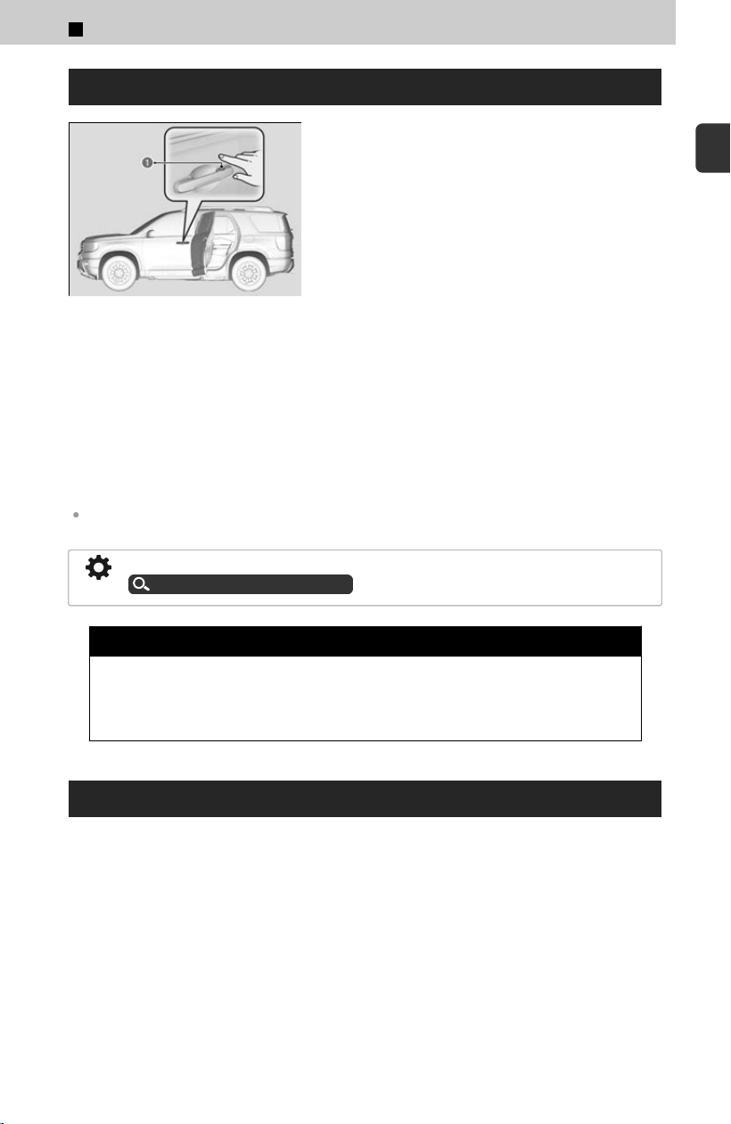
Lock Presetting
a Door Lock Sensor
The vehicle will automatically lock after you lock
the doors in adv
ance then close the doors and
tailgate.
Activate lock presetting after closing the driver’s
door.
[1] Touch the door lock sensor on the front door
or pr
ess the lock button on the remote
transmitter.
≫
Alert sounds and lock presetting is activated.
[2] Close all doors and the tailgate.
≫
Some exterior lights flash and a beeper sounds
when vehicle locks.
Make sure the doors and tailgate are locked
bef
ore moving away from the vehicle.
Lock presetting will be reset if a door or the tailgate is opened before the vehicle has locked
completely.
You can turn this function on and off.
Customized Features
u
P.239
3 WARNING
Opening or closing the power tailgate on someone’s hands or fing
ers can
cause serious injury. Make sure all hands and fingers, especially children’s,
are clear of the power tailgate.
Unlocking the Doors Using a Key
If the unlock button of the keyless remote does not work, use the built-in key instead.
The keyhole is behind the door handle.
1
Before Driving > Locking/Unlocking
57
1
Before Driving
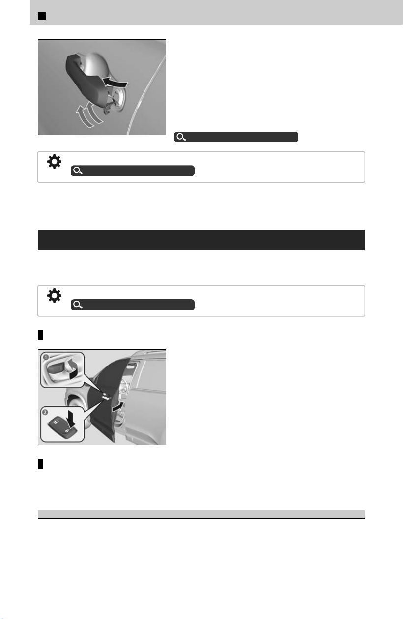
Pull and hold the outer handle.
Insert the built-in key into the key cylinder from
below the handle and then turn it.
When unlocking the driver’s door by turning the
built-in key, the security alarm will begin to
sound.
You can deactivate the alarm.
Security System Alarm
u
P.49
You can customize the door unlock mode setting.
Customized Features
u
P.239
If you unlock a door with the built-in key while the security system is activated, the
alarm will sound.
Locking a Door Without Using a Key
If you do not have the key on you, or if for some reason you cannot lock a door using
the k
ey, you can lock the door without it.
You can change the lockout protection operation setting.
Customized Features
u
P.239
Locking the front doors
Push the lock tab forward a or push the master
door lock switch in the lock direction b, and
close the door.
≫
When you lock the driver’s door, all the other doors
and tailgate lock at the same time.
Locking the rear doors
Push the lock tab forward and close the door.
Lockout Protection Function
If the vehicle cannot detect the keyless remote, lockout protection activates:
≫
A beeper sounds, some exterior lights flash, the doors unlock, and a message appears on the
driver information interface.
≫
This allows you to open a door in case the keyless remote is still inside the vehicle.
1
Before Driving > Locking/Unlocking
58
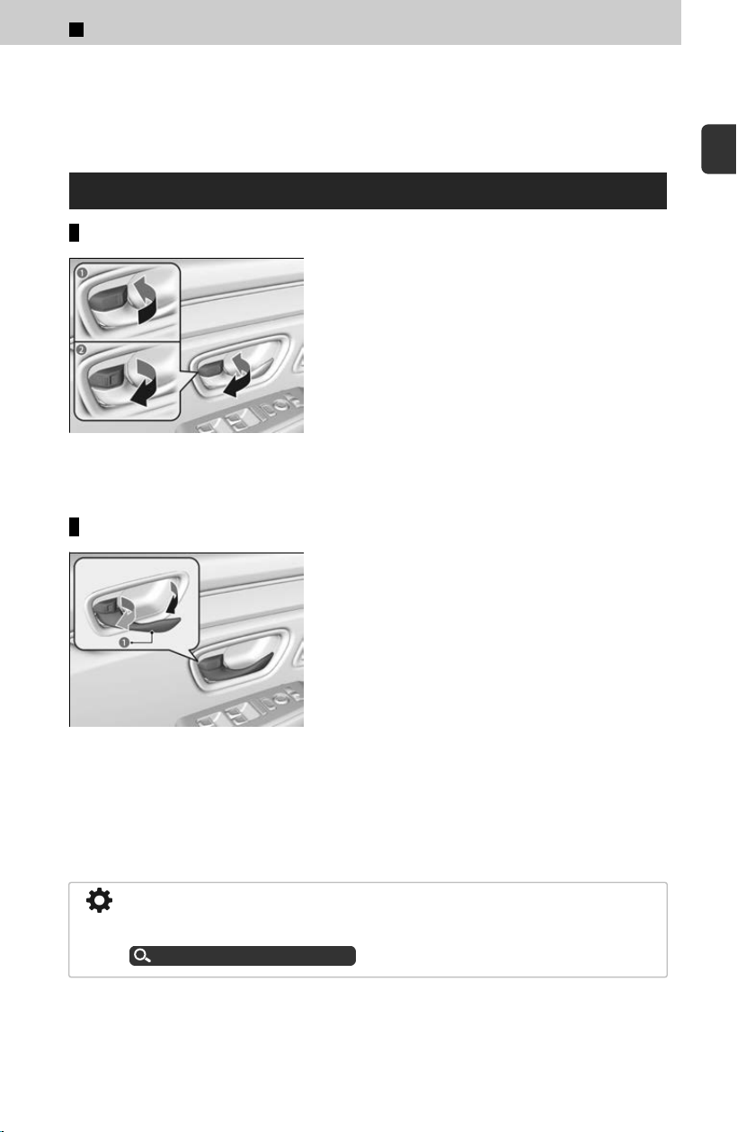
If you do not open a door, all doors relock after 15 seconds.
To avoid non-detection, make sure to keep the keyless remote away from cell phones
and other devices that may cause signal interference.
Locking/Unlocking the Doors from the Inside
Using the lock tab
a To lock
b To unlock
Locking a door: Push the lock tab f
orward.
Unlocking a door: Pull the lock tab rearward.
≫
When you lock the door using the lock tab on the
driver’s door, all the other doors and the tailgate lock
at the same time. When you unlock the door using the
lock tab on the driver’s door, only the driver’s door
and fuel fill door will unlock.
Unlocking using the front door inner handle
a Inner Handle
Pull the front door inner handle.
≫
The door unlocks and opens in one motion.
Unlocking and opening the driver’s door from the inner handle unlocks all the other
doors
.
To avoid all the doors unlocking use the lock tab on the driver’s door to unlock, then
lock again before opening the door.
This setting works for one time only. If you do not want all the doors to be unlocked
all the time, customize the Auto Door Unlock setting to Off using the audio/
information screen.
Customized Features
u
P.239
1
Before Driving > Locking/Unlocking
59
1
Before Driving
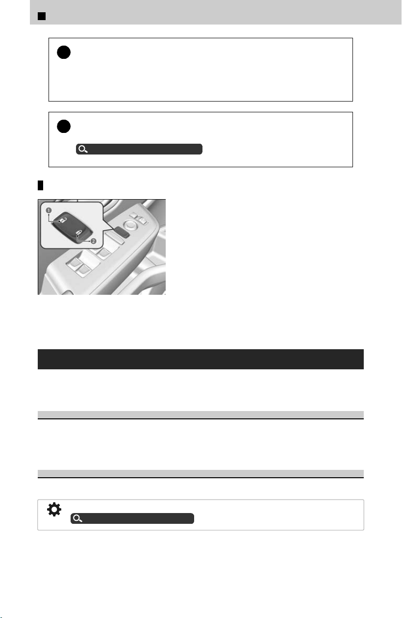
!
The front door inner handles are designed to allow front seat
oc
cupants to open the door in one motion. However, this feature
requires that front seat occupants never pull a front door inner handle
while the vehicle is in motion.
!
Children should always ride in a rear seat where childproof door locks
ar
e provided.
Childproof Door Locks
u
P.61
Using the master door lock switch
a To unlock
b To lock
Press the master door lock switch in as shown to
lock or unlock al
l doors, fuel fill door, and the
tailgate.
≫
When you lock/unlock either of the front doors using
the master door lock switch, all the other doors and
the tailgate lock/unlock at the same time.
Auto Door Locking/Unlocking
Your vehicle locks or unlocks all doors automatically when a certain condition is met.
Drive Lock Mode
All doors and tailgate lock when the vehicle’s speed reaches about 10 mph (15
km
/h).
Driver’s Door Open Mode
All doors and tailgate unlock when the driver’s door is opened.
You can turn off or change to another auto door locking/unlocking setting.
Customized Features
u
P.239
1
Before Driving > Locking/Unlocking
60
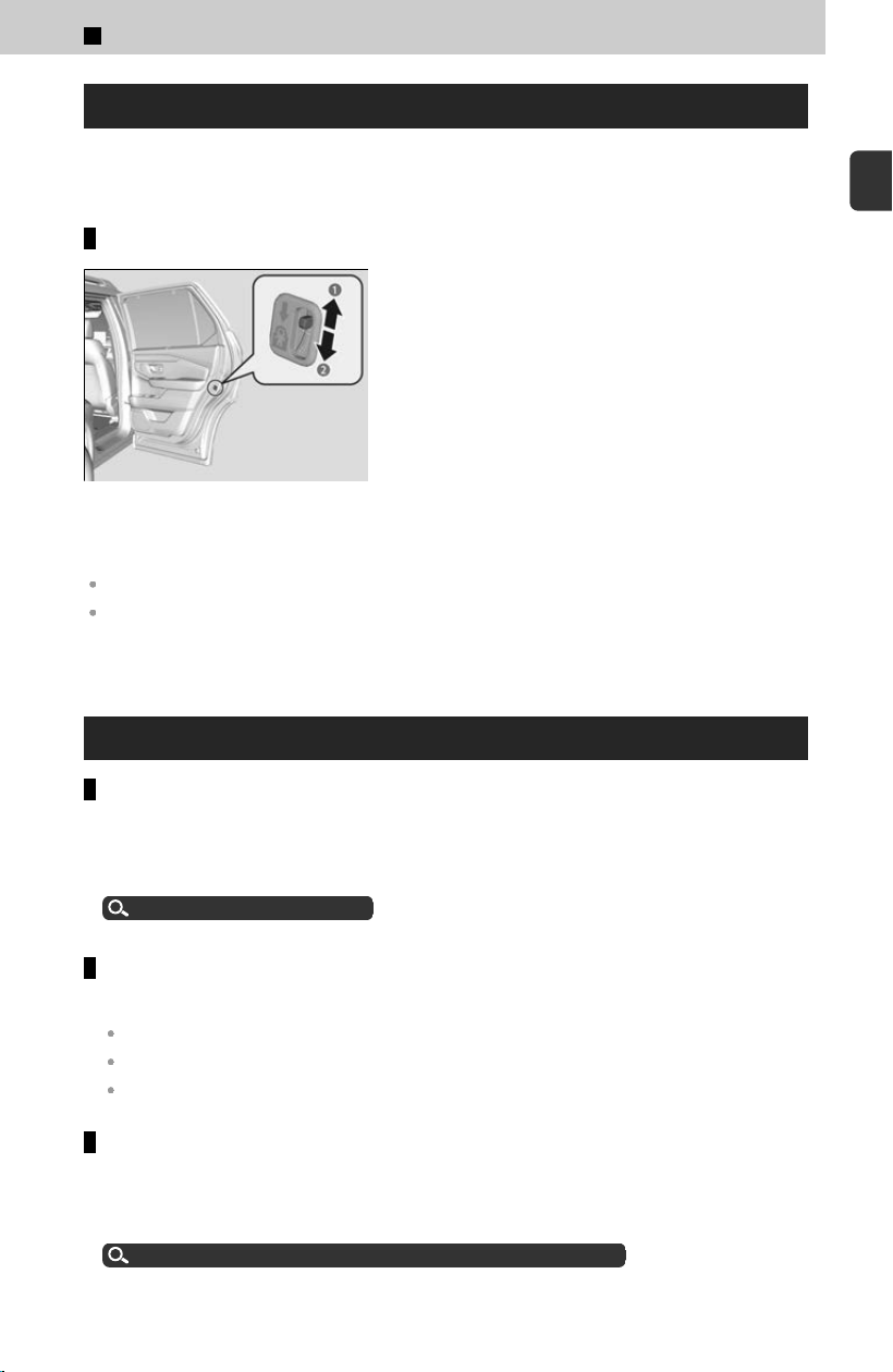
Childproof Door Locks
The childproof door locks prevent the rear doors from being opened from the inside
r
egardless of the position of the lock tab.
Setting the childproof door locks
a Unlock
b Lock
Slide the lever in the rear door to the lock
position, and close the door
.
Open the door using the outside door handle.
To open the door from the inside when the childproof door lock is on, put the lock tab in the
unlock position, lower the rear window, put your hand out of the window, and pull the outside
door handle.
What to Do If
The rear door cannot be opened from inside the vehicle. Why?
Check if the childproof lock is in the lock position. If so, open the rear door with the
outside door handle
.
To cancel this function, slide the lever up to the unlock position.
Childproof Door Locks
u
P.61
Why does the beeper sound when I open the driver’s door?
The beeper sounds when:
The power mode is in ACCESSORY.
The exterior lights are left on.
The Auto Idle Stop is in operation.
Why does a beeper sound when I walk away from the vehicle after I
close the door?
The beeper sounds if you move outside the walk away auto door lock operating
r
ange before the door completely closes.
Locking the Doors and Tailgate (Walk Away Auto Lock®)
u
P.55
1
Before Driving > Locking/Unlocking
61
1
Before Driving

Why is the keyless remote not working properly?
If the distance at which the remote transmitter works varies, the battery is probably
lo
w.
If the LED does not come on when you press a button, the battery is dead.
Replacing the Remote Battery
u
P.387
If there are buildings and obstacles between your vehicle and the keyless remote,
the r
ange will be reduced.
This distance may vary by external electrical interference.
1
Before Driving > Locking/Unlocking
62
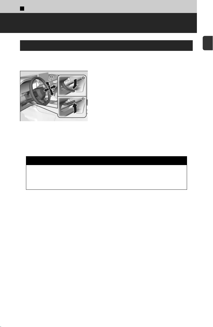
1
Before Driving >
Steering Wheel
Adjusting the Steering Wheel
The steering wheel height and distance from your body can be adjusted so that you
can c
omfortably grip the steering wheel in an appropriate driving posture.
a Release
b Adjust
c Lock
[1] While the vehicle is stopped, push the
s
teering wheel adjustment lever down.
≫
The steering wheel adjustment lever is under
the steering column.
[2] Move the steering wheel up or down, and in
or out
.
≫
Make sure you can see the instrument panel
gauges and indicators.
[3] Pull the steering wheel adjustment lever up
t
o lock the steering wheel in position.
≫
After adjusting the position, make sure you have
securely locked the steering wheel in place by
trying to move it up, down, in, and out.
3 WARNING
Adjusting the steering wheel position while driving may cause you to lose
c
ontrol of the vehicle and be seriously injured in a crash.
Adjust the steering wheel only when the vehicle is stopped.
63
1
Before Driving
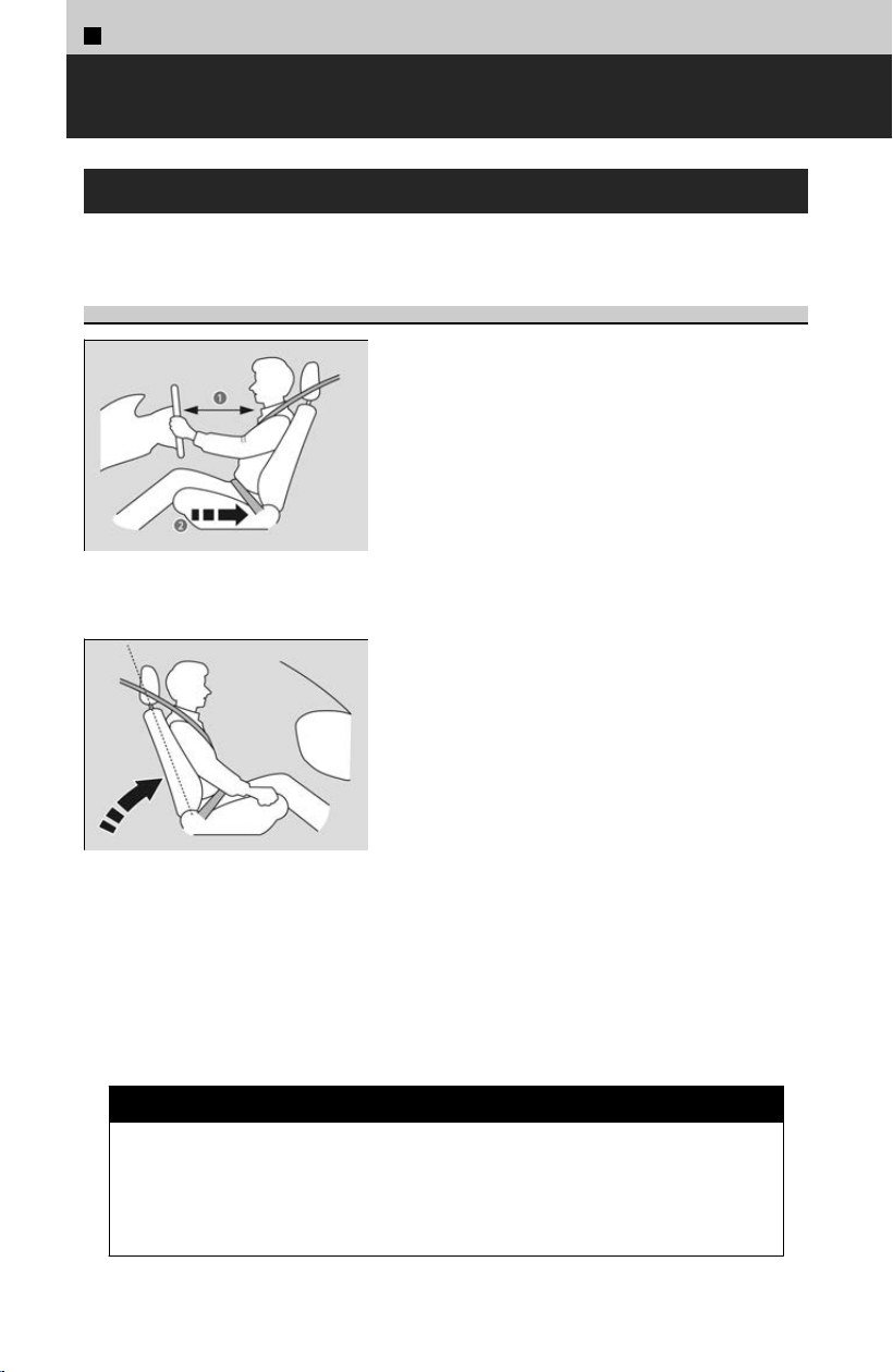
1
Before Driving >
Seats
Adjusting the Seat
Always make seat adjustments before driving.
Maintain a Proper Sitting Position
a Allow sufficient space.
b Move back.
Adjust the driver’s seat as far back as possible
while al
lowing you to maintain full control of the
vehicle. You should be able to sit upright, well
back in the seat and be able to adequately press
the pedals without leaning forward, and grip the
steering wheel comfortably. The passenger’s seat
should be adjusted in a similar manner so that it
is as far back from the front airbag in the
dashboard as possible.
Adjust the driver’s seat-back to a comfortable,
upright position, leaving ample space between
your chest and the airbag cover in the center of
the steering wheel.
The front seat passenger should also adjust their
seat-back to a comfortable, upright position.
Reclining a seat-back so that the shoulder part of the belt no longer rests against the
oc
cupant’s chest reduces the protective capability of the belt. It also increases the
chance of sliding under the belt in a crash and being seriously injured. The farther a
seat-back is reclined, the greater the risk of injury.
The National Highway Traffic Safety Administration and Transport Canada
recommend that drivers allow at least 10 inches (25 cm) between the center of the
steering wheel and the chest.
3 WARNING
Sitting too close to a front airbag can result in serious injury or death if the
fr
ont airbags inflate.
Always sit as far back from the front airbags as possible while maintaining
control of the vehicle.
64
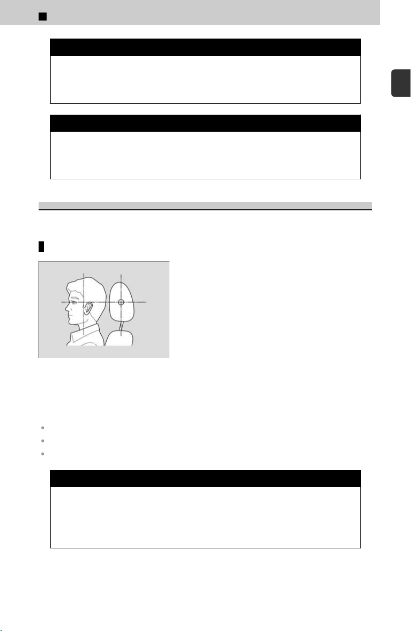
3 WARNING
Reclining the seat-back too far can result in serious injury or death in a
cr
ash.
Adjust the seat-back to an upright position, and sit well back in the seat.
3 WARNING
Sitting improperly or out of position can result in serious injury or death in a
cr
ash.
Always sit upright, well back in the seat, with your feet on the floor.
Head Restraints
Your vehicle is equipped with head restraints in all seating positions.
Adjusting the front and rear outer seat head restraint positions
Position head in the center of the
head restraint.
Head restraints are most effective for protection
ag
ainst whiplash and other rear-impact crash
injuries when the center of the back of the
occupant’s head rests against the center of the
restraint. The tops of the occupant’s ears should
be level with the center height of the restraint.
In order for the head restraint system to work properly:
Do not hang any items on the head restraints, or from the restraint legs.
Do not place any objects between an occupant and the seat-back.
Install each restraint in its proper location.
3 WARNING
Improperly positioning head restraints reduces their effectiveness and
incr
eases the likelihood of serious injury in a crash.
Make sure head restraints are in place and positioned properly before
driving.
1
Before Driving > Seats
65
1
Before Driving
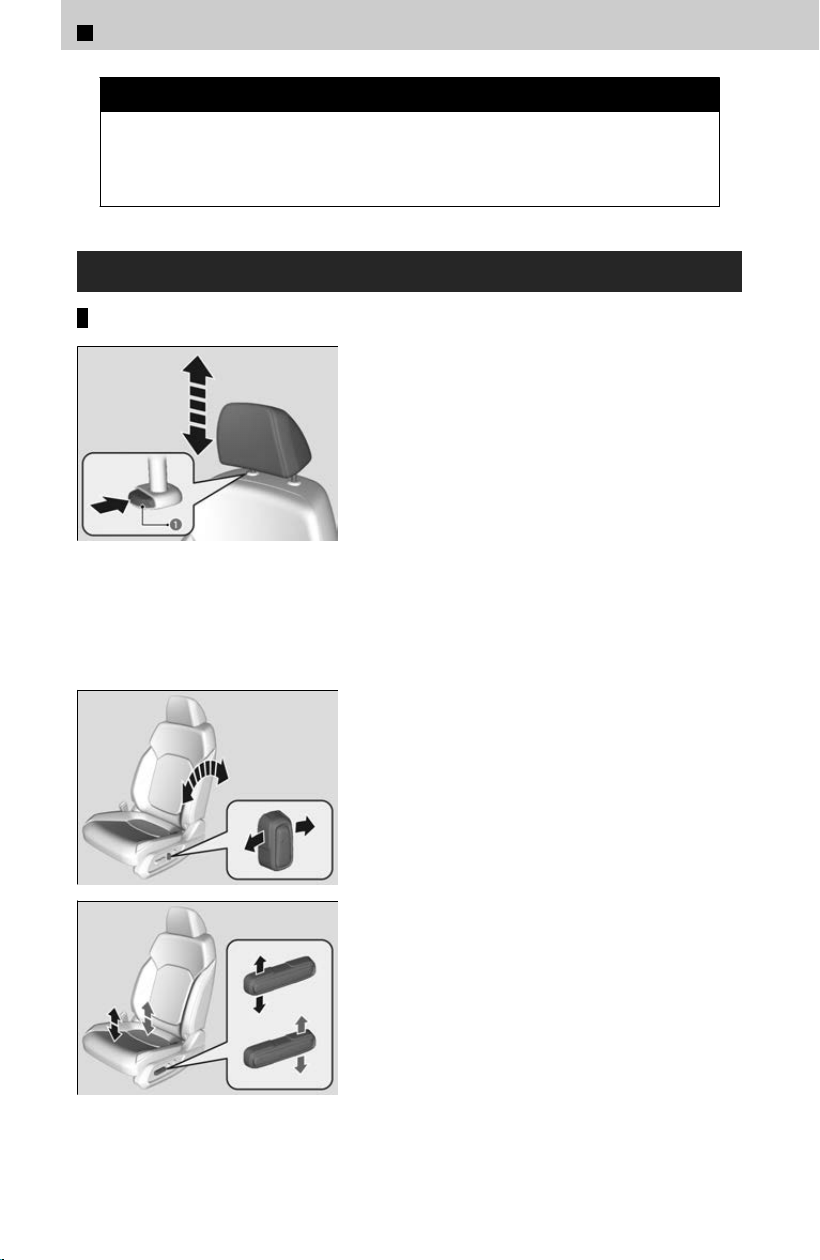
3 WARNING
Failure to reinstall or correctly reinstall, the head restraints can result in
se
vere injury during a crash.
Always replace the head restraints before driving.
Adjusting the Front Seat Positions
Adjusting the front power seat(s)
a Release Button
To raise the head restraint:
Pull it upward.
To lower the head restraint:
Push it down while pressing the release button.
To remove the head restraint:
Pull the restraint up as far as it will go. Then, push
the r
elease button and pull the restraint up and
out.
To reinstall a head restraint:
Insert the legs back in place, then adjust the head
restraint to an appropriate height while pressing
the release button.
≫
Pull up on the restraint to make sure it is locked in
position.
Seat-back Angle Adjustment:
Push forward or pull backward the switch to
change the angle.
Height Adjustment (Driver’s seat only) :
Pull up or push down the switch to raise or lower
the seat.
1
Before Driving > Seats
66
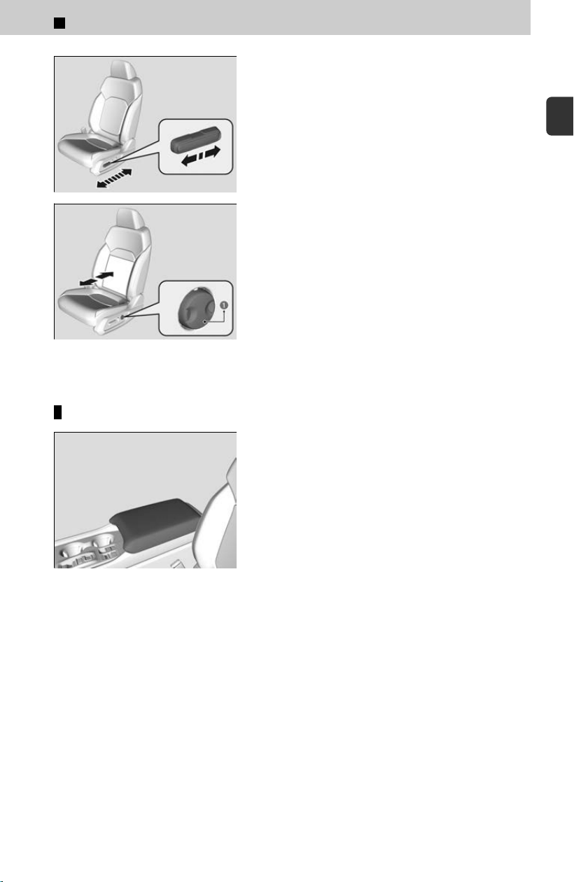
Horizontal Position Adjustment:
Slide the switch to move the seat.
a Lumbar Support Adjustment
Switch
Lumbar Support Adjustment Switch
*
Press the front:
To increase the entire lumbar support.
Press the rear:
To decrease the entire lumbar support.
Using the front seat armrest
The console lid can be used as an armrest.
*: Not available on all models
1
Before Driving > Seats
67
1
Before Driving
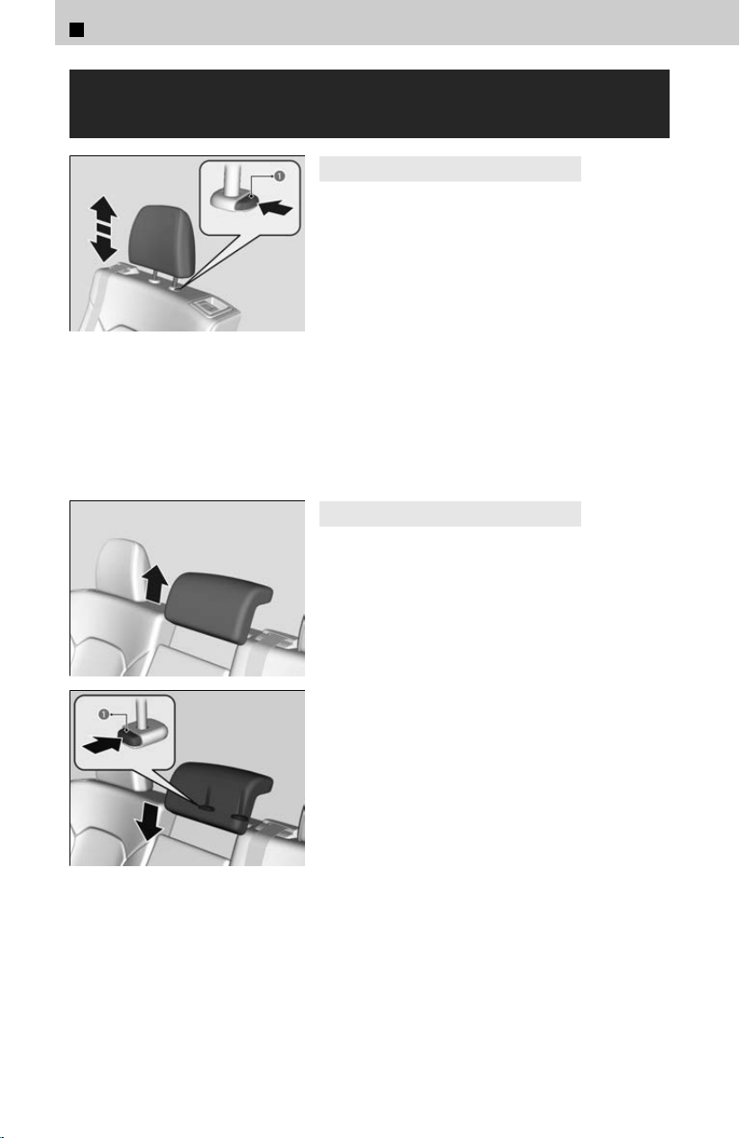
Adjusting the Rear Outer and Center Seat
Positions
a Release Button
4
Rear outer seat head restraints
To raise the head restraint:
Pull it upward.
To lower the head restraint:
Push it down while pressing the release button.
To remove a head restraint:
Pull the restraint up as far as it will go. Then, push
the r
elease button and pull the restraint up and
out.
To reinstall a head restraint:
Insert the legs back in place, then adjust the head
restraint to an appropriate height while pressing
the release button.
≫
Pull up on the restraint to make sure it is locked in
position.
a Release Button
4
Rear center seat head restraint
A passenger sitting in the rear seat should adjust
the height o
f their head restraint to an
appropriate position before the vehicle begins
moving.
To raise the head restraint:
Pull it upward.
To lower the head restraint:
Push it down while pressing the left release
button.
To remove a head restraint:
Pull the restraint up as far as it will go. Then push
the release buttons which are located on both
legs at the same time, and pull the restraint up
and out.
To reinstall a head restraint:
Insert the legs back in place, then adjust the head
restraint to an appropriate height while pressing
the left release button.
≫
Pull up on the restraint to make sure it is locked in
position.
1
Before Driving > Seats
68
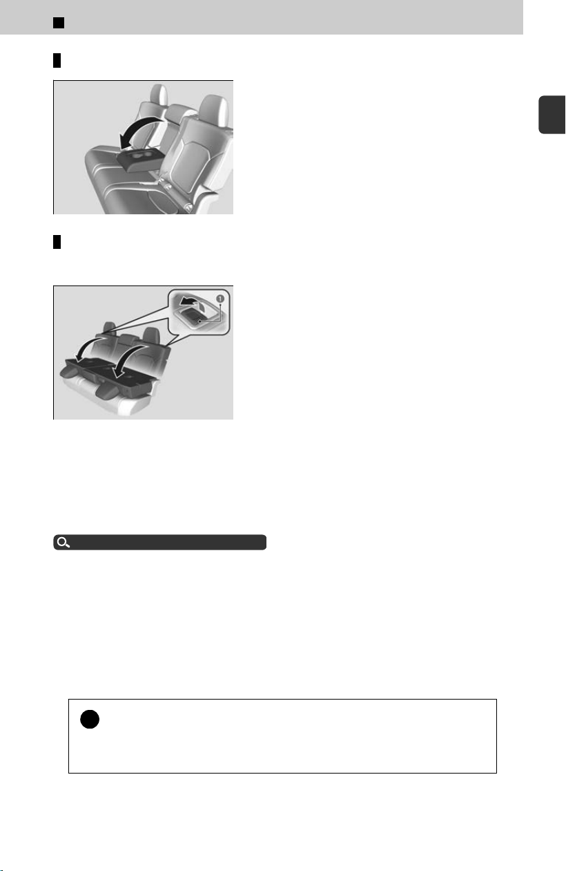
Using the rear seat armrest
Pull down the armrest in the center backrest.
Folding down the rear seats
The rear seats can be folded down separately to allow for additional storage space.
a Release Lever
[1] Lower the rear seat head restraint to its
lo
west position.
[2] Put the armrest back into the seat-back.
[3] Pull the release lever and fold down the seat.
The rear seat-back(s) can be folded down to accommodate bulkier items in the cargo
ar
ea.
Make sure that the folded seat-back does not press against the front passenger seat,
as this can cause the weight sensors in the front passenger seat to work improperly.
Passenger Airbag Off Indicator
u
P.43
The front seat(s) must be far enough forward so they do not interfere with the rear
seats as the
y fold down.
Make sure the seat-back, head restraints and seat cushion are securely latched back
into place before driving. Also, make sure all rear shoulder belts are positioned in
front of the seat-back.
To lock a seat-back upright, push it backwards until it locks, so that the red tabs in the
release lever go down.
When returning the seat-back to its original position, push it firmly back.
!
Make sure all items in the cargo area or items extending to the rear
seats ar
e properly secured. Loose items can fly forward if you have to
brake hard.
1
Before Driving > Seats
69
1
Before Driving
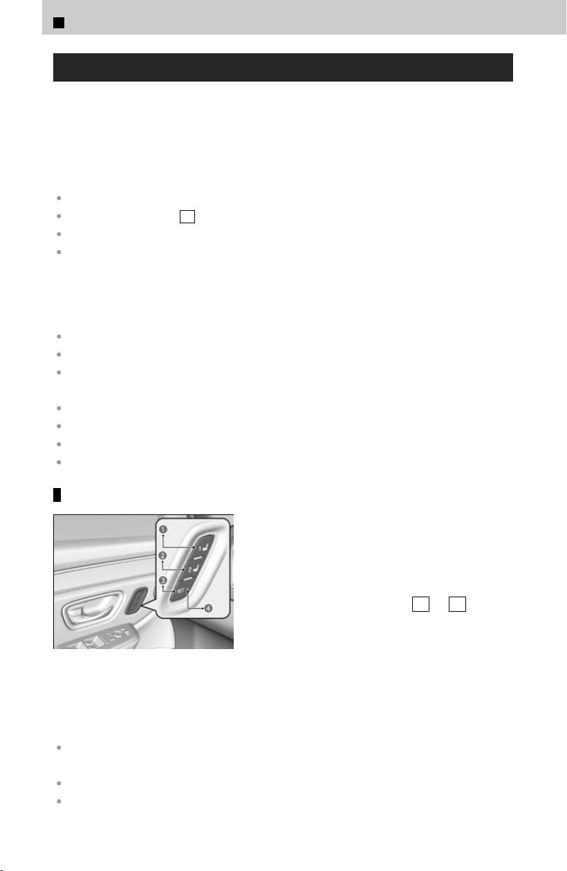
Driving Position Memory System
You can store two driver’s seat and outside mirrors position (except for power
lumbar) with the driving position memor
y system.
When you unlock and open the driver’s door with a keyless remote or keyless access
system, the seat and outside mirrors adjusts to retracted positions of one of the two
preset positions automatically.
The driver’s seat moves rearward depending on the set seating position once you:
Stop the vehicle.
Put the transmission in P .
Turn the engine off.
Open the driver’s door.
Once the power mode is in the ACCESSORY position, the driver’s seat moves forward
t
o the DRIVER 1 or 2 preset position.
System Operation
The system will not operate if:
Either memory button is pressed while the seat or mirrors are in motion.
The seat or mirror positions are adjusted while in operation.
Either of the memorized positions is set fully to the rear.
The system may not recognize a key if:
The key is in close proximity to a cell phone or other wireless device.
Both keys are in the vehicle at the same time.
The Driving Position Memory System is disabled in customized features.
The driver’s door is opened without fully grabbing the door handle.
Storing a position in memory
a Memory Button 1
b Memory Button 2
c SET Button
d Indicator Light
[1] Set the power mode to ON. Adjust the
driv
er’s seat and door mirror to the desired
position.
[2] Press the SET button.
≫
The SET button indicator lights will come on.
[3] Press the memory button 1
or 2 within
five seconds of pressing the SET button.
≫
You will hear the beeper, and the SET button
indicator light goes off.
Set the power mode to ON. Adjust the driver’s seat to the desired position.
After you press the SET but
ton, the storing operation will be canceled when:
You do not press the memory button within five seconds.
You readjust the seat position and door mirror before the double-beep.
1
Before Driving > Seats
70
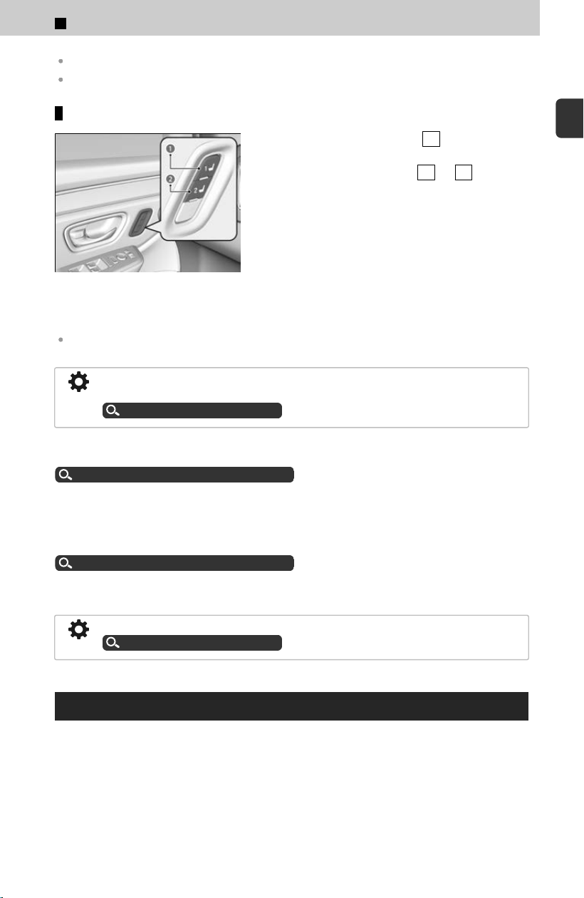
You set the power mode to any position except ON.
The position of the lumbar support is not stored.
Recalling the stored position
a Memory Button 1
b Memory Button 2
[1] Put the transmission into P
.
[2] Apply the parking brake.
[3] Press a memory button ( 1 or 2 ).
≫
The seat and the door mirrors will automatically
move to the memorized position.
Do not perform any operations while the seat is moving automatically. Doing so may cause the
seat to stop.
Using the audio/information screen, you can disable the automatic seat adjustment
function.
Customized Features
u
P.239
Multiple separate accounts can be created for each user.
See the following page for details.
Registering new user information
u
P.208
The transmitter settings may not be switched when you change owner accounts.
If this happens, change to a different account and then try switching to the desired
ac
count again.
For details, please refer to the following page.
Registering new user information
u
P.208
When the door is opened, the driver’s seat moves to the seat position of the account
that las
t used the transmitter.
The driver’s seat easy exit feature can be turned On/Off.
Customized Features
u
P.239
Rear Seat Reminder
This feature alerts you to the possible presence of passengers or items in the rear
seats bef
ore you exit the vehicle. It activates when the vehicle is set to VEHICLE OFF
if the rear doors were opened shortly before or after the vehicle was set to ON.
1
Before Driving > Seats
71
1
Before Driving
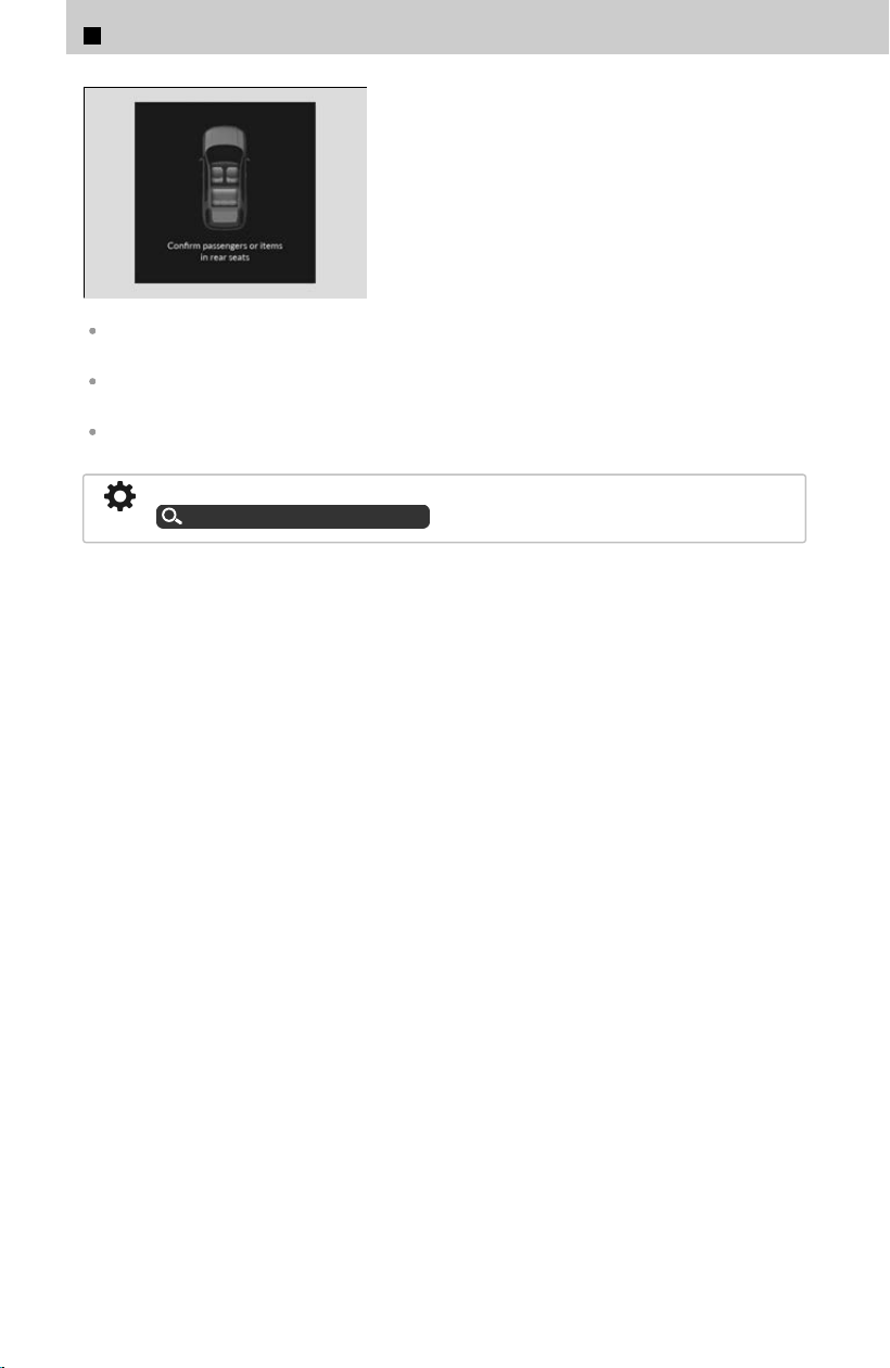
A reminder appears on the driver
information interface and an alert will sound
when the power mode is set to VEHICLE OFF.
When the power mode is set to VEHICLE OFF, the reminder comes on briefly, then the
function is deactivated.
The reminder will not work if the power mode has not been set to ON within 10 minutes of
operating the rear doors.
The system does not detect passengers in the rear seats. Instead, it can detect when a rear
door is opened and closed, indicating that there may be something in the rear seats.
You can turn off the notification setting.
Customized Features
u
P.239
1
Before Driving > Seats
72

1
Before Driving >
Seat Belts
About Your Seat Belts
Seat belts are the single most effective safety device because they keep you
c
onnected to the vehicle so that you can take advantage of many built-in safety
features. They also help keep you from being thrown against the inside of the vehicle,
against any passengers, or out of the vehicle. When worn properly, seat belts also
keep your body properly positioned in a crash so that you can take full advantage of
the additional protection provided by the airbags.
Lap/shoulder seat belts
All five seating positions are equipped with lap/shoulder seat belts with emergency
locking retractors. In normal driving, the retractor lets you move freely while keeping
some tension on the belt. During a collision or sudden stop, the retractor locks to
restrain your body.
The front passenger’s and rear seat belts also have a lockable retractor for use with
child seats.
Child Safety
u
P.19
In addition, seat belts help protect you in almost every type of crash, including:
frontal impacts
side impacts
rear impacts
rollovers
Seat belts cannot completely protect you in every crash. But in most cases, seat belts
can r
educe your risk of serious injury.
Most states and all Canadian provinces and territories require you to wear seat belts.
If a rear seat passenger moves around and extends the seat belt, the lockable
retractor may activate. If this happens, release the retractor by unfastening the seat
belt and allow the belt to retract completely. Then refasten the belt.
3 WARNING
Not wearing a seat belt properly increases the chance of serious injury or
death in a cr
ash, even though your vehicle has airbags.
Be sure you and your passengers always wear seat belts properly.
73
1
Before Driving
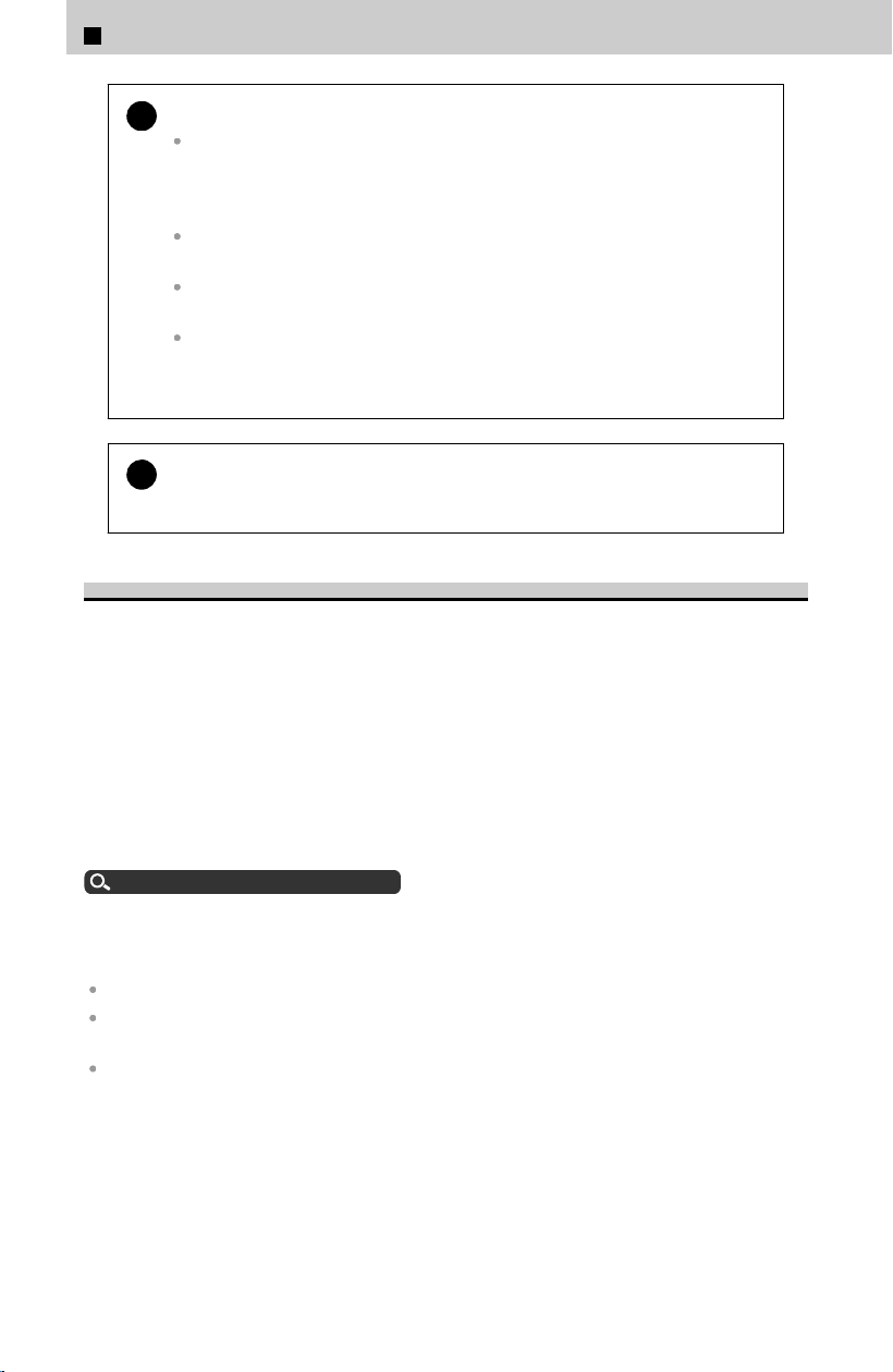
!
Follow these guidelines for proper use:
All occupants should sit upright, well back in the seat, and remain in that
position for the duration of the trip. Slouching and leaning reduce the
effectiveness of the belt and can increase the chance of serious injury in a
crash.
Never place the shoulder part of a lap/shoulder seat belt under your arm or
behind your back. This could cause very serious injuries in a crash.
Two people should never use the same seat belt. If they do, they could be
very seriously injured in a crash.
Do not put any accessories on the seat belts. Devices intended to improve
comfort or reposition the shoulder part of a seat belt can reduce the
protective capability and increase the chance of serious injury in a crash.
!
If you extend the seat belt too quickly, it will lock in place.
If this happens
, slightly retract the seat belt, then extend it slowly.
Seat Belt Reminder
The beeper will periodically sound and the indicator will blink while the vehicle is
mo
ving until the seat belt is fastened.
The indicator will also come on if a front passenger does not fasten their seat belt
within six seconds after the power mode is set to ON.
When no one is sitting in the front passenger’s seat, the indicator will not come on
and the beeper will not sound.
The indicator also may not come on and the beeper may not sound when the
occupant is not heavy enough to trigger the weight sensor. Such occupants (e.g.,
infants and smaller children) should be moved to the rear seat as a deploying front
airbag likely will injure or kill them.
Protecting Child Passengers
u
P.19
The driver information interface uses colors to aid the driver in checking the status of
the pas
sengers.
For the front seating positions:
Green indicates the seat belt is fastened.
An unfastened gray graphic indicates the seat belt is not fastened and an occupant has not
been detected.
An unfastened red graphic indicates the seat belt is unfastened and an occupant has been
detected.
1
Before Driving > Seat Belts
74
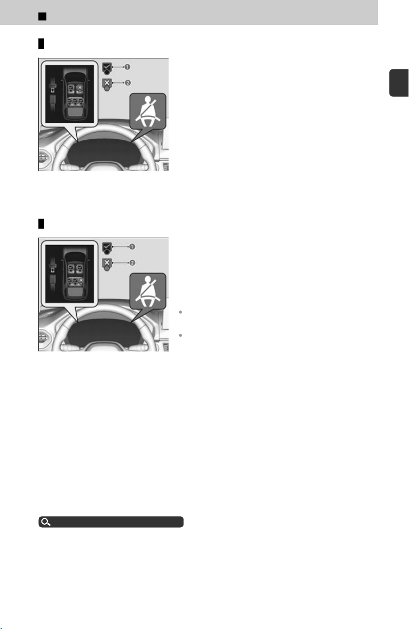
Front seats
a Fastened
b Unfastened
The seat belt system includes an indicator on the
ins
trument panel to remind the driver or a front
passenger or both to fasten their seat belts.
If you set the power mode to ON and a seat belt is
not fastened, a beeper will sound and the
indicator will blink. After a few seconds, the
beeper will stop and the indicator will come on
and remain illuminated until the seat belt is
fastened.
Rear seats
a Fastened
b Unfastened
Your vehicle monitors rear seat belt use.
The Rear seat belt reminder notifies y
ou with the
driver information interface, the beeper sounds,
or both if any of the rear seat belts are not used.
The rear seat belt reminder operates under any of
the following circumstances:
Any of the rear passengers have not fastened their
seat belt since the power mode was set to ON.
Any of the rear seat belts have come off while driving.
The system will not detect a passenger in the rear seats who has not fastened the
seat bel
t.
The driver should check the status of the rear passengers’ seat belts at the start of
each trip and each time a passenger is seated in the rear seats, using the driver
information interface as an aid.
An alert will sound if a passenger in the rear seats unfastens the seat belt while the
vehicle is in motion or if motion resumes while the graphic is red.
The system does not monitor harnesses that are part of a child seat, nor the anchors
of the LATCH system. While the system can inform you that a seat belt is fastened, it
cannot determine whether a child seat is properly installed or used.
Protecting Child Passengers
u
P.19
1
Before Driving > Seat Belts
75
1
Before Driving
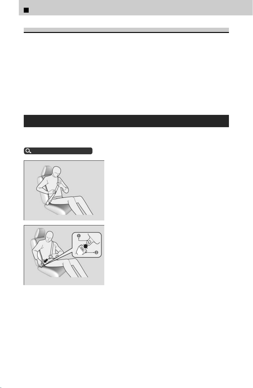
Automatic Seat Belt Tensioners
The front seats and the outer rear seats are equipped with automatic seat belt
t
ensioners to enhance safety.
The tensioners automatically tighten the front seat belts and the outer rear seat belts
during a moderate-to-severe frontal or side collision, sometimes even if the collision
is not severe enough to inflate the front airbags or the driver’s and passenger’s knee
airbags.
The seat belt tensioners can only operate once. If a tensioner is activated, the SRS
indicator will come on. Have a dealer replace the tensioner and thoroughly inspect
the seat belt system as it may not offer protection in a subsequent crash.
Fastening a Seat Belt
After adjusting a front seat to the proper position, and while sitting upright and well
back in the seat:
Adjusting the Seat
u
P.64
[1] Pull the seat belt out slowly.
[2] Insert the latch plate (a) into the buckle
(b), then tug on the belt to make sure the
buckle is secure.
≫
Make sure that the belt is not twisted or caught
on anything.
1
Before Driving > Seat Belts
76
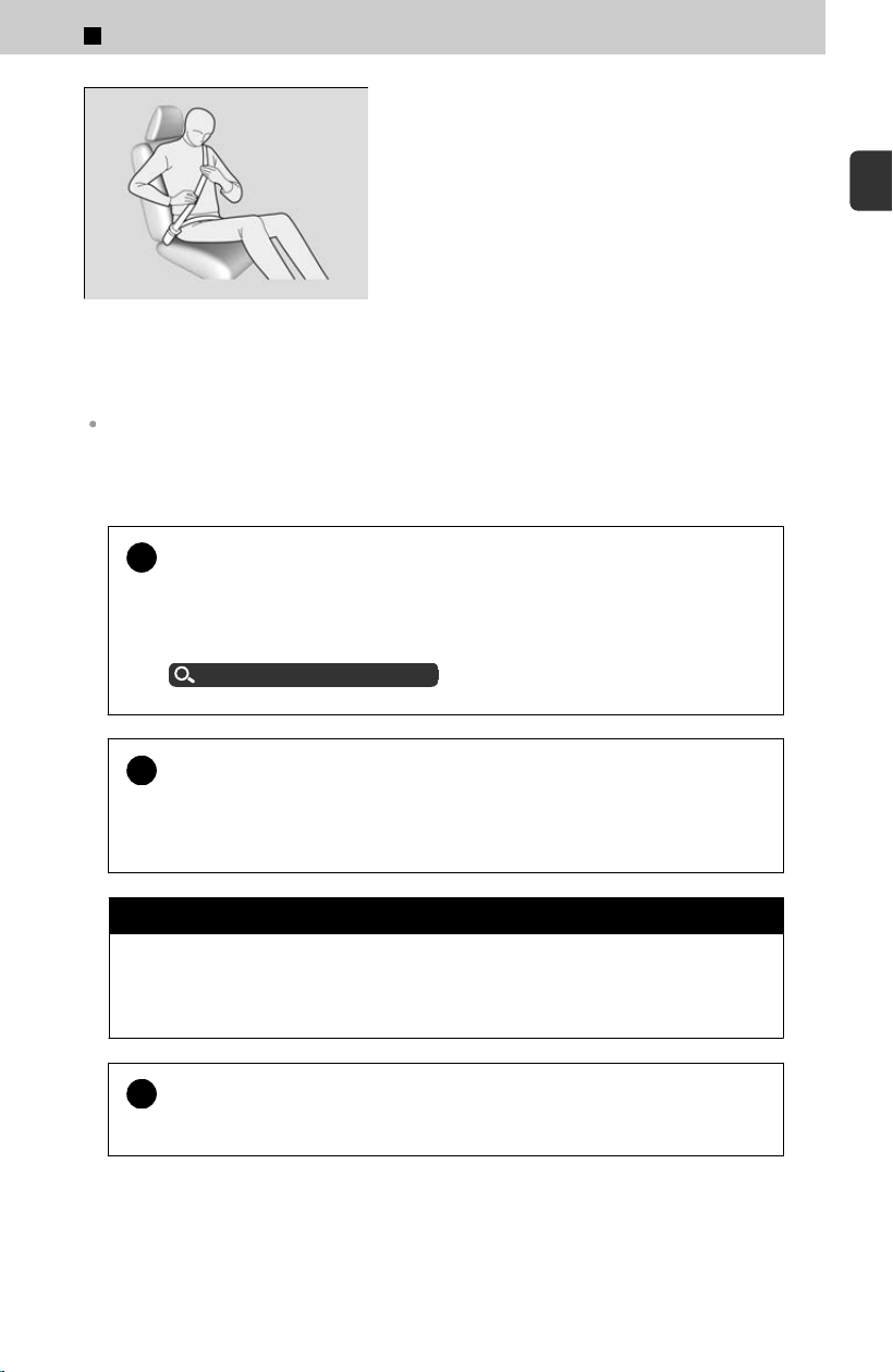
[3] Position the lap part of the belt as low as
possible across your hips (see illustration),
then pull up on the shoulder part of the belt
so the lap part fits snugly. This lets your
strong pelvic bones take the force of a crash
and reduces the chance of internal injuries.
[4] If necessary, pull up on the belt again to
remove any slack, then check that the belt
rests across the center of your chest and
over your shoulder. This spreads the forces
of a crash over the strongest bones in your
upper body.
To release the belt, push the red PRESS button and then guide the belt by hand until it has
retracted completely.
When exiting the vehicle, be sure the belt is properly stowed so that it will not get caught in
the closing door.
!
If the seat belt appears to be locked in a fully retracted position, firml
y
pull out on the shoulder belt once, then push it back in.
Then, smoothly pull it out of the retractor and fasten. If you are unable to
release the seat belt from a fully retracted position, do not allow anyone to sit in
the seat, and take your vehicle to a dealer for repair.
About Your Seat Belts
u
P.73
!
No one should sit in a seat with an inoperative seat belt or one that
does not appear t
o be working correctly.
Using a seat belt that is not working properly may not protect the occupant in a
crash. Have a dealer check the belt as soon as possible.
3 WARNING
Improperly positioning the seat belts can cause serious injury or death in a
cr
ash.
Make sure all seat belts are properly positioned before driving.
!
Never insert any foreign objects into the buckle or retractor
mechanism.
1
Before Driving > Seat Belts
77
1
Before Driving
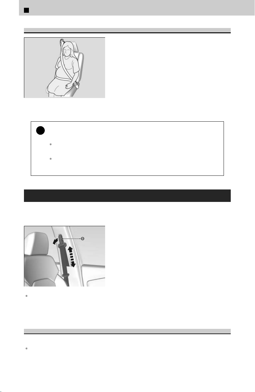
Advice for Pregnant Women
Consider alternative:
If you are pregnant, the best way to protect
yourself and your unborn child when driving or
riding in a vehicle is to always wear a seat belt.
When positioning the seat belt, wear the shoulder
belt section across the chest, avoiding the
abdomen, and keep the lap belt portion as low as
possible across the hips. (See illustration.)
Each time you have a checkup, ask your doctor if it is okay for you to drive.
!
To reduce the risk of injuries to both you and your unborn child that
can be caused b
y an inflating front airbag:
When driving, sit upright and adjust the seat as far back as possible while
allowing full control of the vehicle.
When sitting in the front passenger’s seat, adjust the seat as far back as
possible.
Adjusting the Shoulder Anchor
The front seats have adjustable shoulder anchors to accommodate taller and shorter
oc
cupants.
[1] Move the anchor up and down while pulling
the shoulder anchor (a) outward.
[2] Position the anchor so that the belt rests
across the center of your chest and over your
shoulder.
The shoulder anchor height can be adjusted to four levels. If the belt contacts your neck,
lower the height one level at a time.
After an adjustment, make sure that the shoulder anchor position is secure.
Seat Belt Inspection
Regularly check the condition of your seat belts as follows:
Pull each belt out fully, and look for frays, cuts, burns, and wear.
1
Before Driving > Seat Belts
78

Check that the latch plates and buckles work smoothly and the belts retract easily.
≫
If a belt does not retract easily, cleaning the belt may correct the problem. Only use a mild
soap and warm water. Do not use bleach or cleaning solvents. Make sure the belt is
completely dry before allowing it to retract.
Any belt that is not in good condition or working properly will not provide proper
pr
otection and should be replaced as soon as possible.
A belt that has been worn during a crash may not provide the same level of protection
in a subsequent crash. Have your seat belts inspected by a dealer after any collision.
3 WARNING
Not checking or maintaining seat belts can result in serious injury or death if
the seat bel
ts do not work properly when needed.
Check your seat belts regularly and have any problem corrected as soon as
possible.
1
Before Driving > Seat Belts
79
1
Before Driving
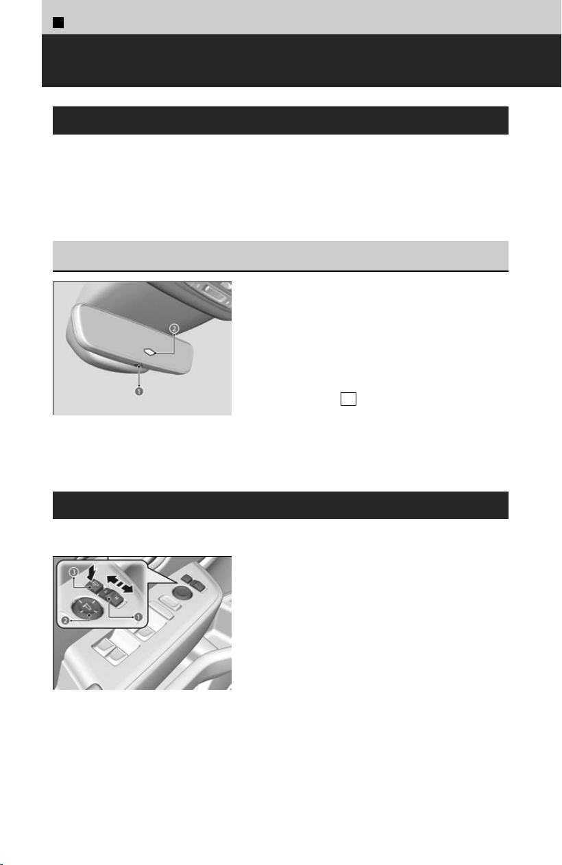
1
Before Driving >
Mirrors
Interior Rearview Mirror
Adjust the angle of the rearview mirror when you are sitting in the correct driving
position.
Adjust the mirrors before you start driving.
Keep the inside and outside mirrors clean and adjusted for best visibility.
Automatic Dimming Rearview Mirror and Power Door
Mirrors
*
a Auto Button
b Sensor
When you are driving after dark, the automatic
dimming r
earview mirror and power door mirror
reduces the glare from headlights behind you.
Press the AUTO button to turn this function on
and off. When activated, the AUTO indicator
comes on.
≫
The auto dimming function cancels when the
transmission is in R
.
Power Door Mirrors
You can adjust the door mirrors when the power mode is in ON.
a L/R Selector Switch:
Select the left or right mirror. After adjusting the
mirror, return the switch to the center position.
b Mirror Position Adjustment Switch:
Press the switch left, right, up, or down to move
the mirror.
c Press the folding button to fold in and out
the door mirrors.
*
*: Not available on all models
80
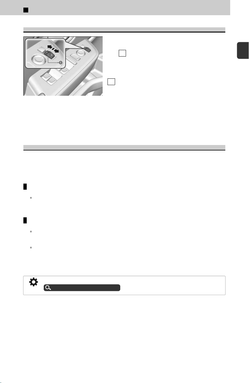
Reverse Tilt Door Mirror
a Selector Switch
If activated, either side door mirror automatically
til
ts downward when you put the transmission
into R : this improves close-in visibility on the
selected side of the vehicle when backing up. The
mirror automatically returns to its original
position when you take the transmission out of
R .
To activate this feature, set the power mode to ON and slide the selector switch to the
lef
t or right side.
Automatic Folding Door Mirror Function
*
When the door is locked or unlocked via the remote transmitter or keyless access
s
ystem, the door mirrors will automatically fold in or return to their previous position,
even when the power mode is set to OFF.
Folding in the door mirrors
Press the lock button on the remote transmitter or touch the door lock sensor on any door.
≫
The mirrors start folding in automatically.
Folding out the door mirrors
Press the unlock button on the remote transmitter or grab the door handle on any door.
≫
The mirrors start folding out automatically.
If you use the folding button to fold the door mirrors, the auto folding door mirror function
will not work.
Door mirrors will not fold automatically when locking from inside the vehicle using
the lock tab or mas
ter door lock switch.
You can turn the automatic folding door mirror function on and off.
Customized Features
u
P.239
*: Not available on all models
1
Before Driving > Mirrors
81
1
Before Driving
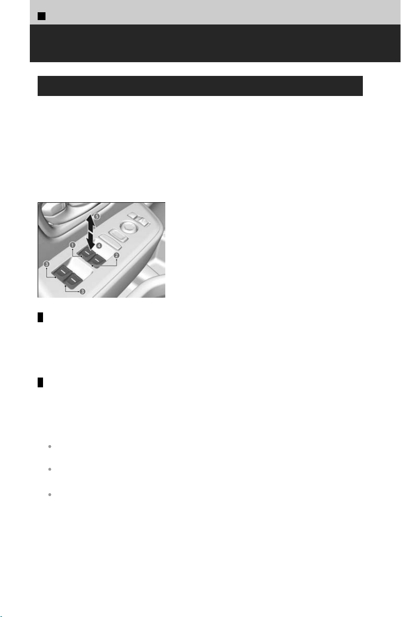
1
Before Driving >
Windows
Opening/Closing the Power Windows
The power windows can be opened and closed when the power mode is in ON, using
the s
witches on the doors.
The driver’s side switches can be used to open and close all the windows. The power
window lock button on the driver’s side must be switched off to open and close the
windows from anywhere other than the driver’s seat.
When the power window lock button is pushed in, the indicator comes on and you can
only operate the driver’s window. Turn the power window lock button on if a child is in
the vehicle.
a Driver’s Window Switch
b Front Passenger’s Window Switch
c Rear Passenger’s Window Switch
d Open
e Close
Manual operation
To open: Push the s
witch down lightly, and hold it until the desired position is
reached.
To close: Pull the switch up lightly, and hold it until the desired position is reached.
Automatic operation
To open: Push the s
witch down firmly.
To close: Pull the switch up firmly.
The window opens or closes completely. To stop the window at any time, push or
pull the switch briefly.
The power windows can be operated for up to 10 minutes after you set the power mode to
VEHICLE OFF.
Opening either front door cancels this function.
Auto Reverse
If a power window senses resistance when closing automatically, it will stop closing and
reverse direction.
If the auto reverse function is activated due to a malfunction or impact caused by
the r
oad surface or driving conditions and the window cannot be closed
automatically, you can close it by continuously pulling up the switch briefly.
82
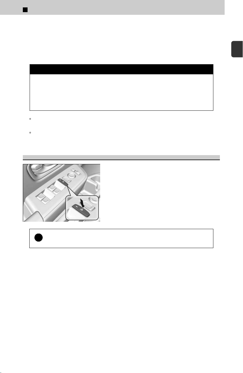
While driving with any of the windows open, you may hear a booming, throbbing, or
helicopter-type noise or pressure. This is called wind buffeting. This is a normal
occurrence that can be minimized.
If you hear a wind buffeting noise with any of the windows open, lower all of the
other windows slightly or open the panoramic roof
*
to the comfort position.
3 WARNING
Closing a power window on someone’s hands or fing
ers can cause serious
injury.
Make sure your passengers are away from the windows before closing
them.
The driver’s window auto reverse function is disabled when you continuously pull up the
switch.
The auto reverse function stops sensing when the window is almost closed to ensure that it
fully closes.
Power Window Lock Button
When the power window lock button is set to ON
(indicator on), any window other than that on the
driver’s side will not operate.
!
Turn the power window lock button on if a child is in the vehicle.
*: Not available on all models
1
Before Driving > Windows
83
1
Before Driving
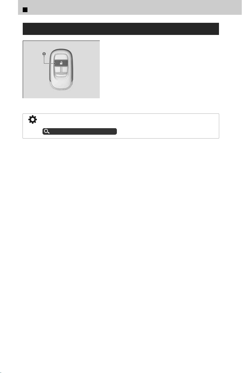
Opening the Windows with the Remote
a Unlock Button
To open:
Press the unlock button a, and then within 10
sec
onds, press it again and hold it.
You can turn off or on the feature to open the windows with the keyless remote
setting using the audio/information screen.
Customized Features
u
P.239
1
Before Driving > Windows
84
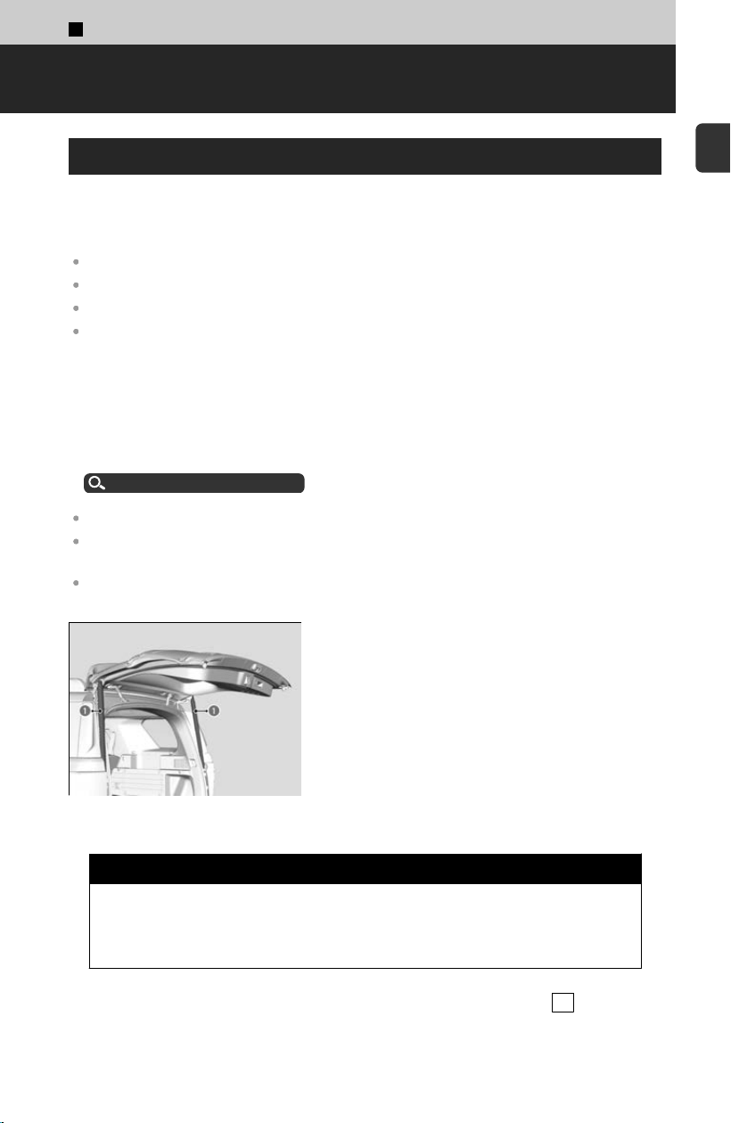
1
Before Driving >
Tailgate
Precautions for Opening/Closing the Tailgate
Always make sure individuals and objects are clear of the tailgate before opening or
closing it
.
The power tailgate may not open or close under the following conditions:
You start the engine while the tailgate is automatically opening or closing.
The vehicle is parked on a steep hill.
The vehicle sways in a strong wind.
The tailgate or the roof is covered with snow or ice.
When operating the power tailgate, make sure there is enough space around your
v
ehicle. People near the tailgate may be seriously hurt if the tailgate hits or closes on
their heads. Be especially cautious if children are around.
Keep the tailgate closed while driving to:
≫
Avoid possible damage.
≫
Prevent exhaust gas from leaking into the vehicle.
Carbon Monoxide Gas
u
P.30
Do not leave the keyless remote in the vehicle when you get out. Carry it with you.
Even if you are not carrying the keyless remote, you can unlock the tailgate while someone
else with the remote is within range.
Do not leave the keyless remote inside the cargo area and close the tailgate. The beeper
sounds and the tailgate cannot be closed.
a Tailgate Support Struts
Make sure cargo or other items do not touch the
tailg
ate support struts.
3 WARNING
Anyone caught in the path of a tailgate that is being opened or closed can
be seriousl
y injured.
Make sure people are clear of the tailgate before opening or closing it.
The power tailgate can be opened/closed when the transmission is in P .
85
1
Before Driving
If the power tailgate meets resistance while opening or closing, the auto reverse feature
reverses the direction. The beeper sounds three times.
The beeper sounds when you start driving while the power tailgate is still open or closing.
3 WARNING
Opening or closing a power tailgate while any part of a passenger is in the
tailg
ate’s operating path can cause serious injury.
Make sure all passengers or objects are clear of the tailgate operating range
before opening or closing the tailgate.
!
Be careful not to hit your head on the tailgate or to put your hands
betw
een the tailgate and the cargo area when closing the tailgate.
!
While the engine is idling and you are storing or picking up cargo from
the car
go area or by using a forward and back kicking motion under
the passenger side of the rear bumper for hands free access
*
, do not
stand in front of the exhaust pipe. You may get burned.
!
Do not allow any passenger in the cargo space. They may get hurt
during har
d braking, a sudden acceleration, or a crash.
!
Do not push or pull on the power tailgate when it is being
aut
omatically opened or closed.
!
Forcibly opening or closing the power tailgate while in operation can
def
orm the tailgate frame.
!
Installing aftermarket components other than Honda Genuine
Ac
cessories on the power tailgate may prevent it from fully opening or
closing.
*: Not available on all models
1
Before Driving > Tailgate
86
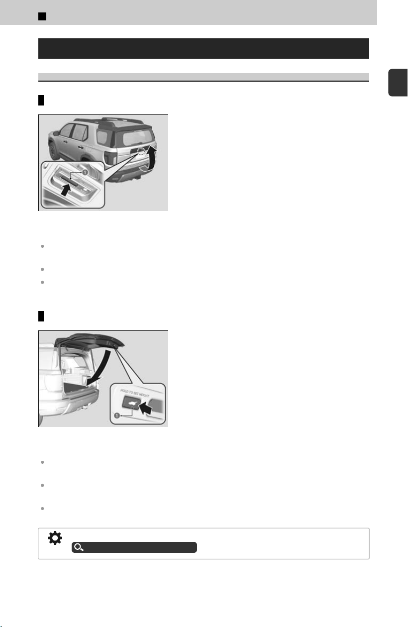
Opening/Closing the Power Tailgate
Using the Tailgate Outer Handle
Opening the tailgate
a Outer Handle
If you press the outer handle of the tailgate for no
long
er than one second, the tailgate opens
automatically.
≫
The beeper sounds.
If you are carrying the keyless remote, you do not have to unlock the tailgate before opening
it.
If you want to open the tailgate manually, press the outer handle for more than one second.
If you press the outer handle again while the power tailgate is moving, it will stop. Press the
outer handle, and the power tailgate will reverse direction.
Closing the tailgate
a Tailgate Inner Button
Press the button a on the tailg
ate to close the
power tailgate.
≫
The beeper sounds.
Do not touch the sensors located on both sides of the tailgate. The power tailgate does not
close if you touch either sensor when you are trying to close the tailgate.
Be careful not to scratch the sensors with a sharp object. If scratched, they can be damaged,
and the power tailgate closing feature may malfunction.
If you press the button again while the power tailgate is moving, it will stop. Press and release
the button again, and the power tailgate will reverse direction.
You can change the power tailgate operation setting on and off.
Customized Features
u
P.239
1
Before Driving > Tailgate
87
1
Before Driving
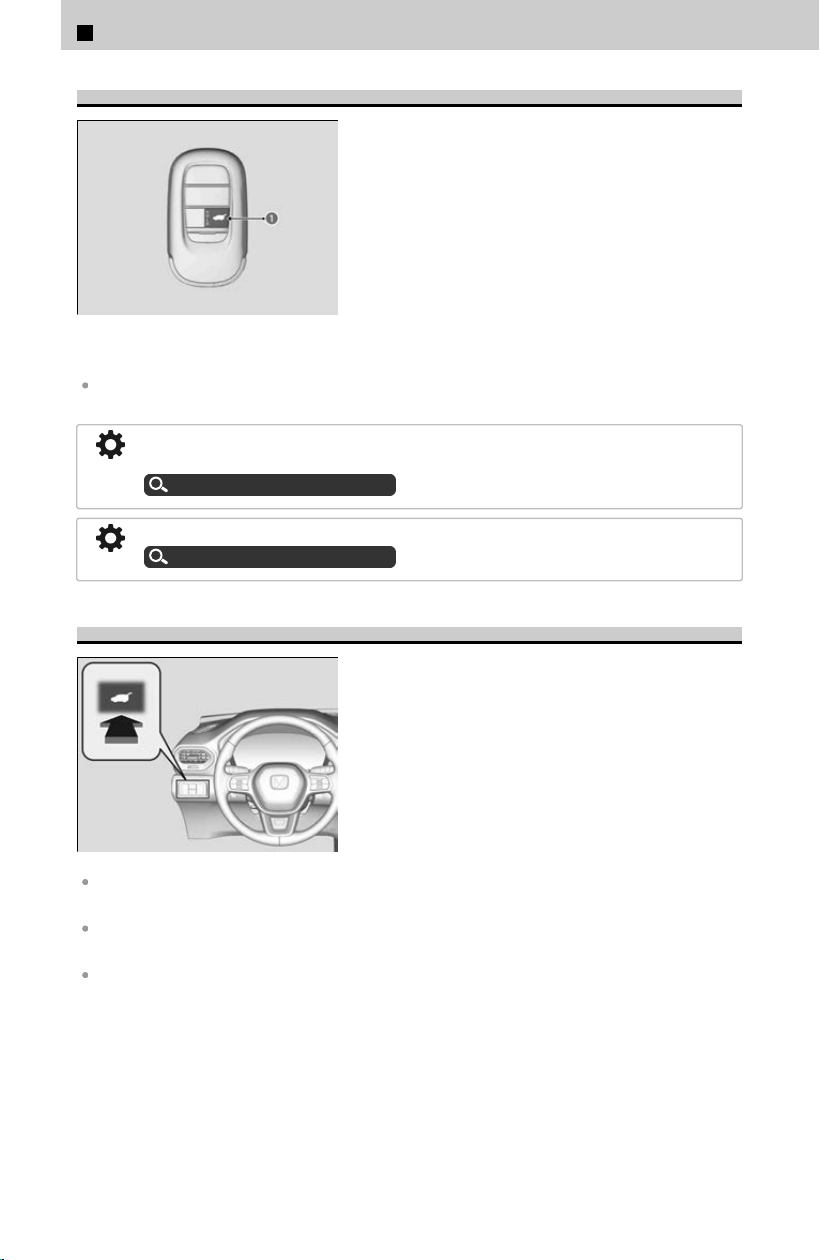
Using the Remote Transmitter
a Power Tailgate Button
Press the power tailgate button for more than one
sec
ond to operate when the power mode is in
VEHICLE OFF.
≫
Some exterior lights flash and the beeper sounds.
If you press the button again while the power tailgate is moving, it will stop. Press the button
for more than one second, and the power tailgate will reverse direction.
Anytime: The power tailgate unlocks and opens at the same time. This is the default
setting.
Customized Features
u
P.239
When Unlocked: The tailgate opens when all doors are unlocked.
Customized Features
u
P.239
Using the Power Tailgate Button
To open or close the power tailgate, press the
power tailgate button for about one second.
≫
Some exterior lights flash and the beeper sounds.
If you press the button again while the power tailgate is moving, it will stop. Press the button
for about one second, and the power tailgate will reverse direction.
If you close the power tailgate when all the doors are locked, the power tailgate locks
automatically.
If you replace the 12-volt battery or the power tailgate fuse while the tailgate is open, the
power tailgate may be disabled. The power tailgate resumes once you manually close the
tailgate.
1
Before Driving > Tailgate
88
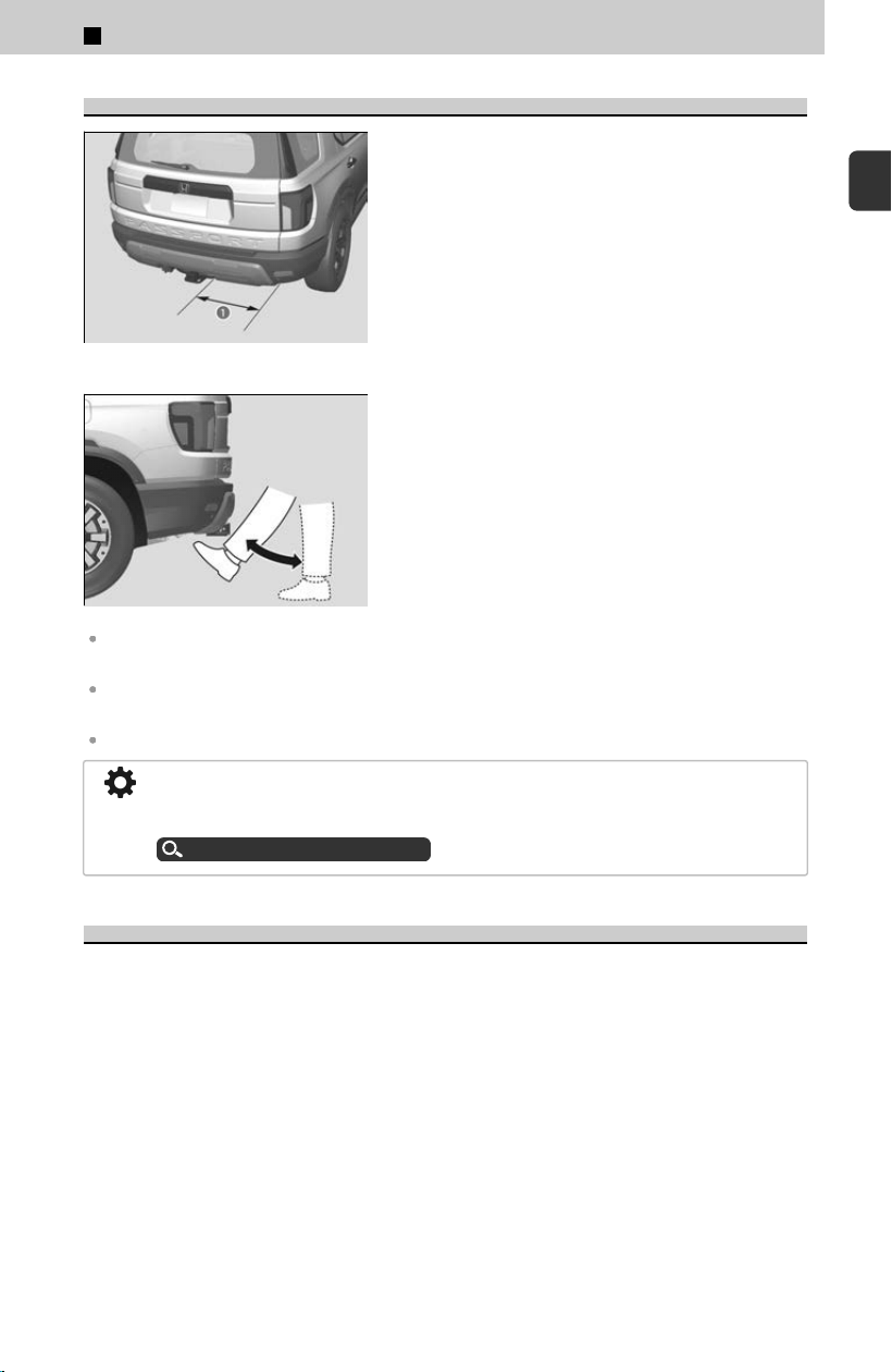
Using the Hands Free Access
*
a Operation Range
Use a forward and back kicking motion for about
1 second under the passenger side of the rear
bumper to open or close the power tailgate while
carrying the keyless remote.
≫
Some exterior lights will flash and a beeper will
sound, then the tailgate will begin to move.
This function will not operate if you don’t have the keyless remote on you. Please make sure
you have the keyless remote on you.
During rain or in other instances when the vehicle becomes wet, the sensor may not properly
detect your foot motion.
If you hold your foot under the bumper for too long, the power tailgate does not open or close.
When performing work on or around the rear section of the vehicle, you may
inadvertently open or close the tailgate. To prevent this from happening, you can turn
off this feature.
Customized Features
u
P.239
Power Tailgate Walk Away Close
*
When you walk away from the vehicle while carrying the keyless remote, the power
tailg
ate will automatically close.
*: Not available on all models
1
Before Driving > Tailgate
89
1
Before Driving
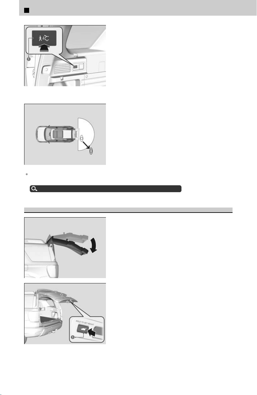
a Walk Away Close Button
[1] Carry the keyless remote and press the walk
aw
ay close button.
≫
The indicator on the walk away close button will
turn green when the walk away close is
activated.
[2] Walk at least 3 feet (1.0 m) away from the
vehicle within 30 seconds of pressing the
walk away close button.
≫
Some exterior lights flash and a beeper sounds,
then the power tailgate begins to close.
When auto lock function is set to ON, the vehicle will automatically lock when all doors and
the tailgate have closed.
Locking the Doors and Tailgate (Walk Away Auto Lock®)
u
P.55
Programming Tailgate Position
[1] Open the tailgate to the desired position.
a Tailgate Inner Button
[2] Press and hold the tailgate inner button.
≫
You will hear one long beep, followed by two
short beeps.
1
Before Driving > Tailgate
90
If the tailgate is only slightly opened, the position cannot be programed, even if you
push the tailgate inner button.
If you want to reprogram the power tailgate to open all the way, manually raise the
tailgate to its upper−most position and follow the directions in step 2.
Power Tailgate Fall Detection
Automatically lowers the power tailgate when there is a possibility that the fully
opened po
wer tailgate can fall down by its own weight (for example, with snow on the
tailgate).
≫
The beeper sounds while the power tailgate lowers.
If you try to manually close the power tailgate immediately after it fully opens, the power
tailgate fall detection may activate.
!
Once the power tailgate fall detection activates, wait until the power
tailg
ate fully closes. Keep away from the power tailgate when it is in
motion.
!
If the power tailgate fall detection constantly activates, consult a
dealer
.
Auto-Closer
If you manually close the power tailgate, it latches automatically.
!
Keep your hands away from the tailgate when you manually close the
tailg
ate and let it latch automatically. It is dangerous to put your hands
around the tailgate as it starts to latch itself.
1
Before Driving > Tailgate
91
1
Before Driving
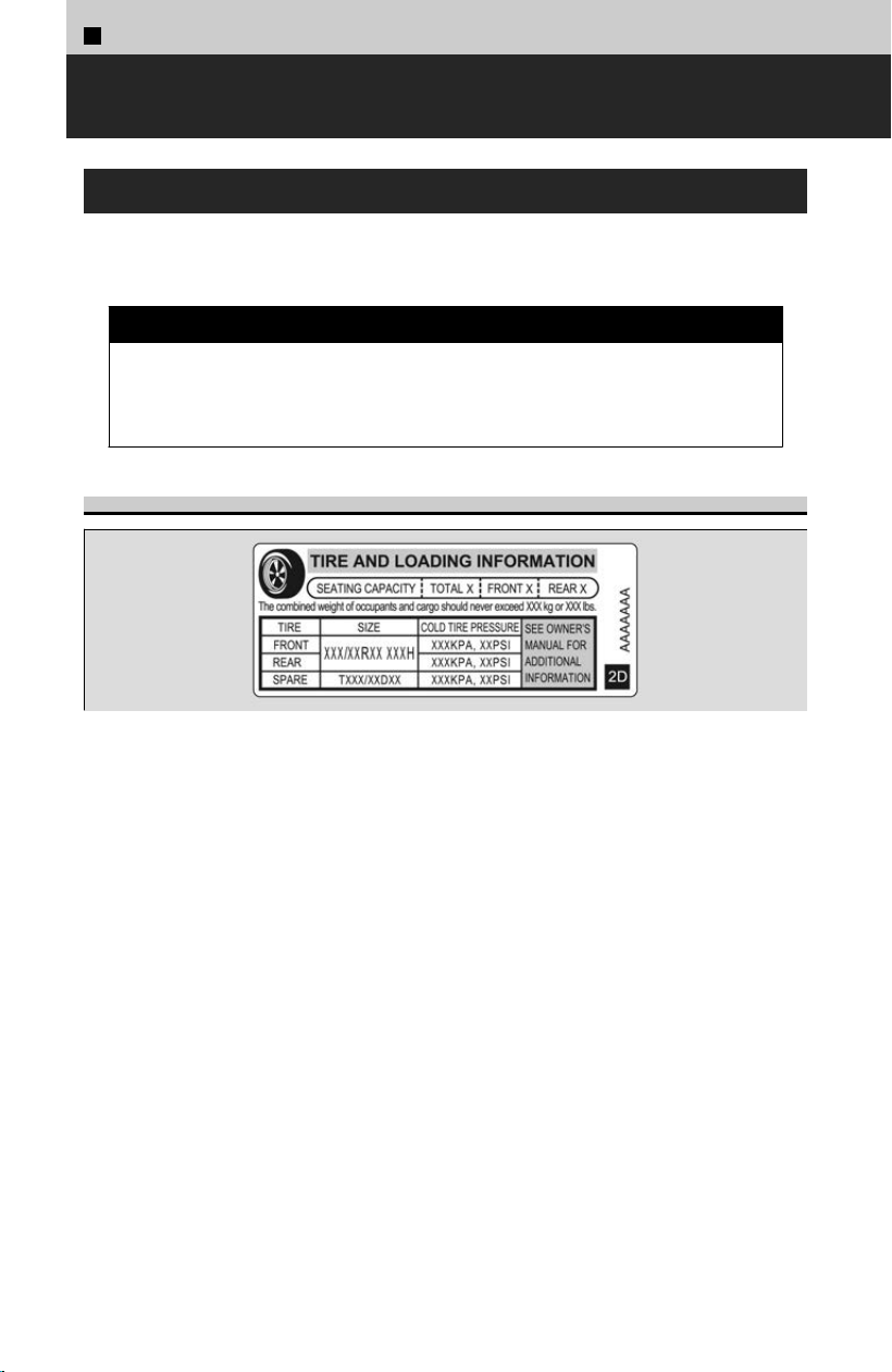
1
Before Driving >
Maximum Load Limit
About Maximum Load Limit
The maximum load for your vehicle is 948 lbs (430 kg). See the Tire and Loading
Inf
ormation label attached to the driver’s doorjamb.
3 WARNING
Overloading or improper loading can affect handling and stability and cause
a cr
ash in which you can be hurt or killed.
Follow all load limits and other loading guidelines in this manual.
Label Example
This figure includes the total weight of all occupants, cargo, and accessories, and the
tongue load if you are towing a trailer.
Steps for Determining Correct Load Limit -
[1]
L
ocate the statement “The combined weight of occupants
and cargo should never exceed XXX kg or XXX lbs.” on your
vehicle’s placard.
[2]
Determine the combined weight of the driver and
passengers that will be riding in your vehicle.
[3]
Subtract the combined weight of the driver and passengers
from XXX kg or XXX lbs.
[4]
The resulting figure equals the available amount of cargo
and luggage load capacity. For example, if the “XXX” amount
equals 1,400 lbs. and there will be five 150 lb. passengers
in your vehicle, the amount of available cargo and luggage
load capacity is 650 lbs. (1,400 - 750 (5 x 150) = 650 lbs.)
92
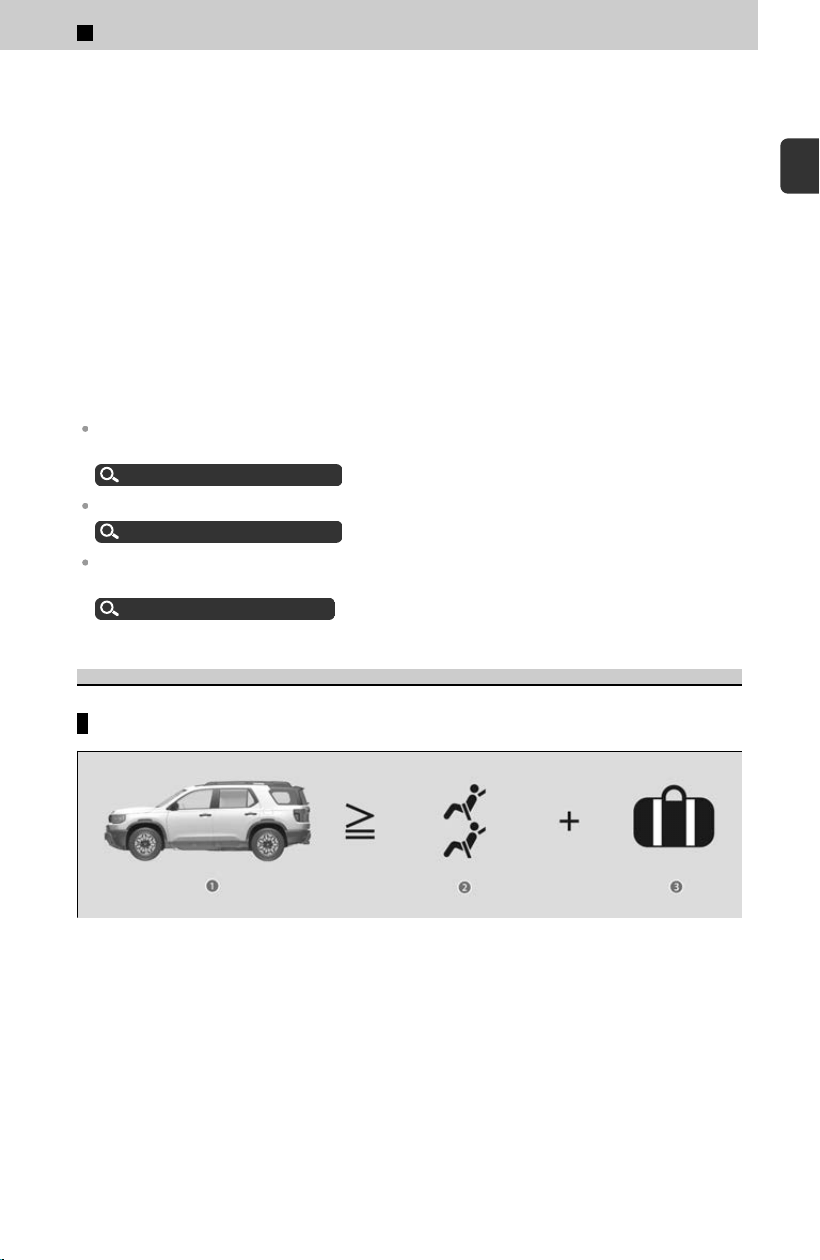
[5]
Determine the combined weight of luggage and cargo being
loaded on the vehicle. That weight may not safely exceed
the available cargo and luggage load capacity calculated in
step 4.
[6]
If your vehicle will be towing a trailer, load from your trailer
will be transferred to your vehicle. Consult this manual to
determine how this reduces the available cargo and luggage
load capacity of your vehicle.
In addition, the total weight of the vehicle, all occupants, accessories, cargo, and
tr
ailer tongue load must not exceed the Gross Vehicle Weight Rating (GVWR) or the
Gross Axle Weight Rating (GAWR). Both are on a label on the driver’s doorjamb.
Gross Vehicle Weight Rating (GVWR): The maximum allowable weight of the vehicle, all
occupants, all accessories, all cargo, and the tongue load.
About Specifications
u
P.416
Gross Axle Weight Rating (GAWR): The maximum allowable weight of the vehicle axle.
About Specifications
u
P.416
Towing a Trailer: See Towing a Trailer to determine whether your vehicle is designed to tow a
trailer.
Towing Preparation
u
P.95
Load Limits Example
Example 1
a Max Load 948 lbs (430 kg)
b Passenger Weight 150 lbs x 2 = 300 lbs (68 kg x 2 = 136 kg)
c Cargo Weight 648 lbs (294 kg)
1
Before Driving > Maximum Load Limit
93
1
Before Driving
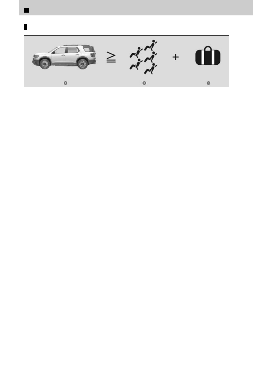
Example 2
a Max Load 948 lbs (430 kg)
b Passenger Weight 150 lbs x 5 = 750 lbs (68 kg x 5 = 340 kg)
c Cargo Weight 198 lbs (90 kg)
1
Before Driving > Maximum Load Limit
94
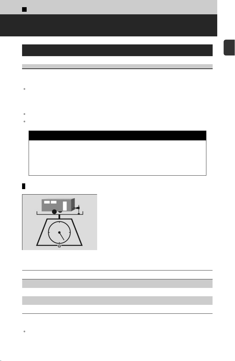
1
Before Driving >
Towing a Trailer
Towing Preparation
Towing Load Limits
Your vehicle can tow a trailer if you carefully observe the load limits, use the proper
equipment
, and follow the towing guidelines. Check the load limits before driving.
Check if all loads are within limits at a public scale. If a public scale is not available, add the
estimated weight of your cargo load to the weight of your trailer (as quoted by the
manufacturer), and then measure the tongue load with an appropriate scale or tongue gauge
or estimate it based on cargo distribution.
Refer to the trailer owner’s manual for additional information.
Avoid towing a trailer during your vehicle’s first 600 miles (1,000 km) for a break-in period.
3 WARNING
Exceeding any load limit or improperly loading your vehicle and trailer can
cause a cr
ash in which you can be seriously hurt or killed.
Check the loading of your vehicle and trailer carefully before starting to
drive.
Total trailer weight
a Total Load
Do not exceed the maximum allowable weight of
the tr
ailer, cargo, and everything in or on it shown
in the table. Towing loads in excess of this can
seriously affect vehicle handling and performance
and can damage the engine and drivetrain.
Number of occupants Total trailer weight
2 5,000 lbs (2,268 kg)
3 4,750 lbs (2,155 kg)
4 4,500 lbs (2,041 kg)
5 4,250 lbs (1,928 kg)
Each weight limit is calculated based on the following conditions:
Occupants fill seats from the front of the vehicle to the back
95
1
Before Driving
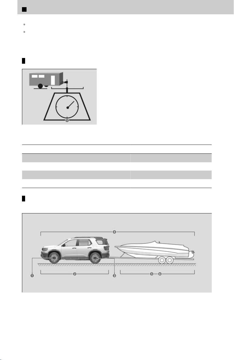
Each occupant weighs 150 lbs (68 kg)
Each occupant has 17.6 lbs (8 kg) cargo in the cargo area
Any additional weight, cargo, or accessories reduce the maximum trailer weight and
maximum t
ongue load.
Tongue load
a Tongue Load
The weight of the tongue with a fully loaded
tr
ailer on the hitch should be approximately:
Boat trailers: 5 – 15% of the total trailer weight
Other trailers: 10 – 15% of total trailer weight
Number of occupants Tongue load
2 500 lbs (227 kg)
3 475 lbs (215 kg)
4 450 lbs (204 kg)
5 425 lbs (193 kg)
How to weigh the trailer loads using the public scale
Check each weight in the order indicated as shown.
a Front gross axle weight
b Gross vehicle weight
c Rear gross axle weight
d Gross combined weight
e Hitched trailer weight
1
Before Driving > Towing a Trailer
96

f Unhitched trailer weight
If you cannot weigh the rear axle, subtract (a) from (b).
The maximum gross combined weight (d) decreases by 2% for every 1,000 feet (305
meters) of elevation.
To calculate the tongue load, subtract (e) from (f).
Refer to the trailer owner’s manual for additional information.
Table for the Each Weight’s Limit (except for the tongue load)
Weight limit for
Front gross axle 3,064 lbs (1,390 kg)
Gross vehicle 5,820 lbs (2,640 kg)
Rear gross axle 3,274 lbs (1,485 kg)
Gross combined 10,163 lbs (4,610 kg)
Fully load the vehicle and trailer. An attendant who watches the scale is needed as
all occupants should stay in the vehicle.
Towing Equipment and Accessories
Towing generally requires a variety of supplemental equipment. To ensure the best
qualit
y, we recommend that you purchase Honda equipment whenever possible.
Make sure that all equipment is properly installed and maintained, and that it meets federal,
state, province/territory, and local regulations.
Consult your trailer sales or rental agency if any other items are recommended or required for
your towing situation.
Consult your trailer maker for proper installation and setup of the equipment.
Improper installation and setup can affect the electrical components, handling, stability, and
braking performance of your vehicle.
The lighting and wiring of trailers can vary by type and brand. If a connector is required, it
should only be installed by a qualified technician.
Trailer packages and products including ball mount kit, hitch harness kit, trailer hitch kit, etc.
available at a dealer.
Trailer brakes
u
P.98
1
Before Driving > Towing a Trailer
97
1
Before Driving
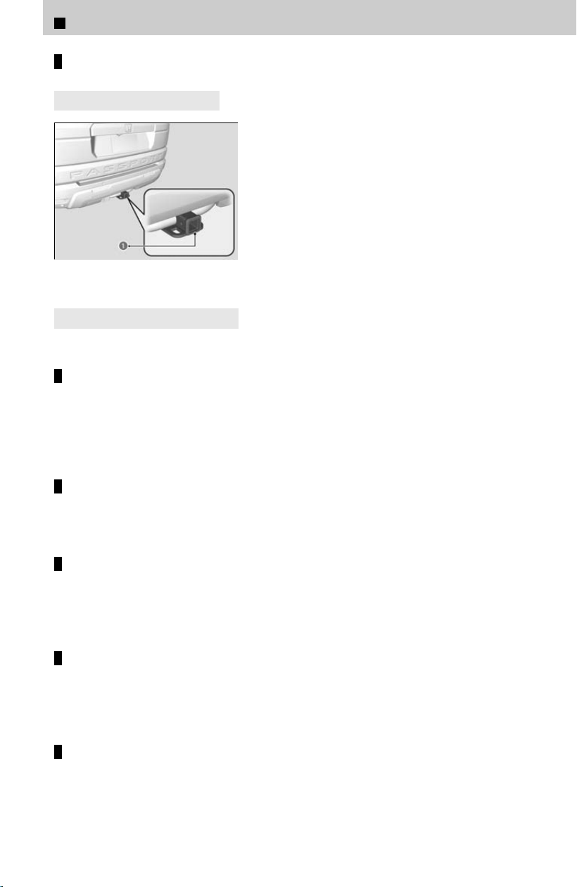
Hitches
4
Models with trailer hitch
a Trailer hitch
Your vehicle has a class 3 trailer hitch as standard
equipment
.
4
Models without trailer hitch
The hitch must be of an approved type and properly bolted to the underbody.
Weight distribution hitches
Your vehicle is designed to tow without the need for a load distributing hitch. If you
wish t
o use one, please consult your trailer maker for proper installation and set-up.
Improper set-up could degrade the handling, stability, and braking performance of
your vehicle.
Safety chains
Always use safety chains when you tow a trailer. Leave enough slack to allow the
tr
ailer to turn corners easily, but do not allow the chains to drag on the ground.
Sway control
This device can be used if your trailer tends to sway. Your trailer maker can tell you
what kind o
f sway control you need and how to install it. Improper installation could
degrade the handling and stability of your vehicle.
Trailer mirrors
Many states, provinces, and territories require special exterior mirrors when towing
a tr
ailer. Install special mirrors whenever you cannot clearly see behind you, or if
the trailer creates a blind spot.
Trailer brakes
Recommended for any trailer with a total weight of 1,000 lbs (450 kg) or more:
1
Before Driving > Towing a Trailer
98
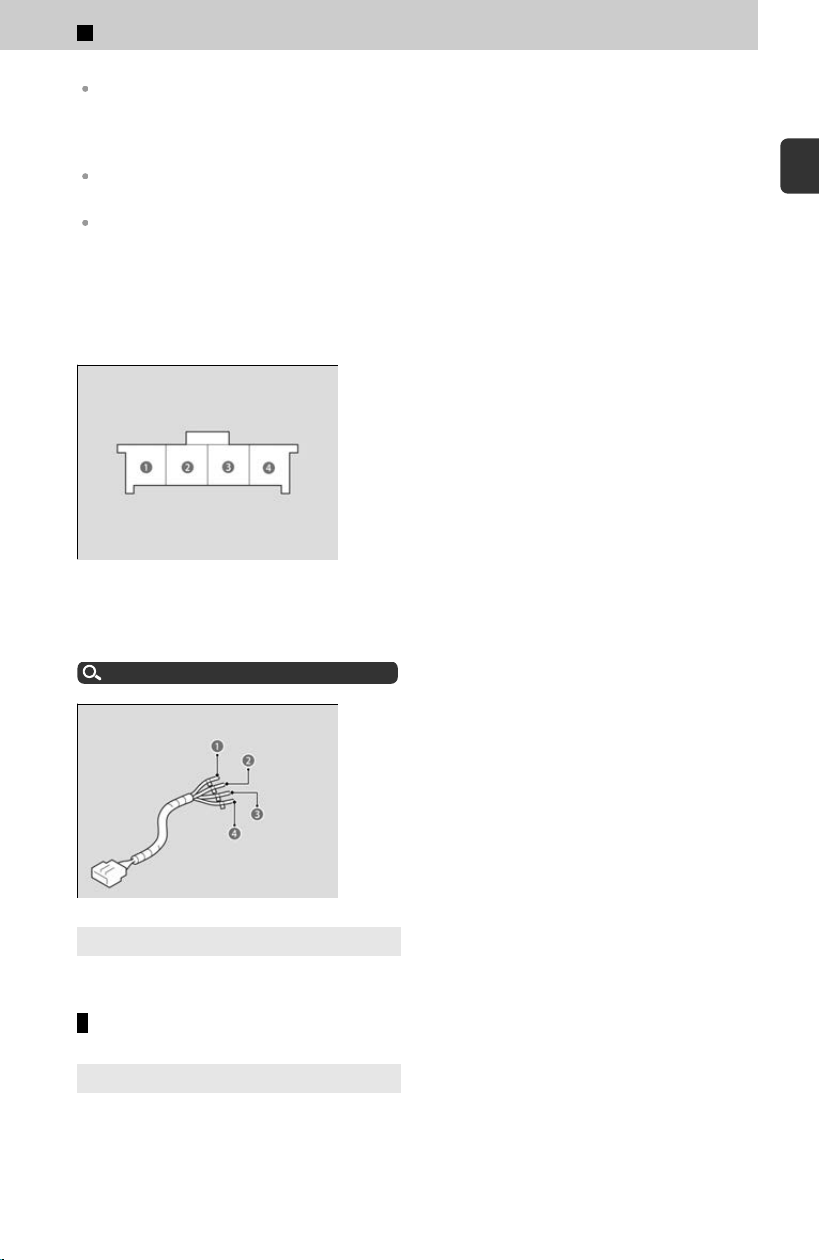
There are two common types of trailer brakes: surge and electric. Surge brakes are common
for boat trailers, since the brakes will get wet. If you choose electric brakes, be sure they are
electronically actuated. Do not attempt to attach trailer brakes to your vehicle’s hydraulic
system, as it will lower braking effectiveness and create a potential hazard.
The 4-pin gray connector installed in your vehicle has all of the circuits required to install
most electric trailer brake controllers.
Have a qualified mechanic install your trailer brake controller following the trailer brake
controller manufacturer’s instructions. Failure to properly install the trailer brake controller
may increase the distance it takes for you to stop your vehicle when towing a trailer.
Trailer brake controller connector
The 4-pin gray connector is located under dashboard near the driver’s side interior
fuse bo
x.
a Ground (Black)
b Electric Brake (Pink)
c Stop (Violet)
d +B (20A) (Green)
Trailer hitch harness
The trailer hitch harness is used to install the controller for the electric trailer brakes.
Inser
t the trailer brake fuse into the engine compartment fuse box.
Engine Compartment Fuse Box
u
P.402
a +B (20A) (Blue)
b Brake Lights (Sky Blue)
c Electric Brake (Brown)
d Ground (Black)
4
Models with 7-pin trailer connector
The trailer hitch harness and trailer brake fuse are stored in the glove box.
Trailer light
4
Models with 7-pin trailer connector
The 7-pin trailer connector is needed for your trailer lights. When inserting the
c
onnector to the socket, check if the connector and the socket are free of dirt,
moisture, or other foreign material.
1
Before Driving > Towing a Trailer
99
1
Before Driving
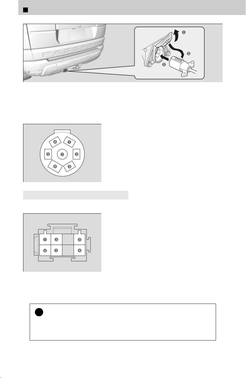
a Pull the socket lid to open.
b Insert the 7-pin trailer connector into the socket.
c Hook the lid retaining tab onto the socket retaining tab.
7-Pin’s wiring color codes and their purpose:
a +B Charge (Green)
b Right Turn signal and brake lights (Red)
c Electric Brake (Pink)
d Ground (Black)
e Left Turn signal and brake lights (Light
Green)
f Tail lights (Black)
g Back-up lights (Blue)
4
Models without 7-pin trailer connector
The trailer lighting connector is located behind the rear panel lining in the cargo area.
a Right Turn signal and brake lights (Red)
b Back-up lights (Blue)
c +B Charge (Green)
d Tail lights (Black)
e Electric Brake (Pink)
f Left Turn signal and brake lights (Light
Green)
We recommend that you have a dealer install a Honda wiring harness and converter.
They are designed for your vehicle.
!
Trailer lights and equipment must comply with federal, state, province/
t
erritory, and local regulations.
Check with your local trailer sales or rental agency for the requirements in the
area where you plan to tow.
1
Before Driving > Towing a Trailer
100

!
Use only Honda genuine electrical connections.
Do not c
onnect the trailer lamp wiring directly to the vehicle’s tail lamp. Doing
so may damage the vehicle’s other electrical components, resulting in
malfunction.
Trailer Stability Assist
Helps stabilize the vehicle and trailer when the trailer severely sways.
Trailer stability assist is not a function that prevents the vehicle and trailer from swaying.
Avoid high speeds, abrupt steering, improper trailer load, and sudden braking to keep the
trailer from swaying. When swaying too severely, the system becomes ineffective, and you
may lose control of your vehicle, causing the trailer to roll over or get damaged.
How trailer stability assist works
u
P.101
Trailer towing sway is caused by crosswinds, improper tongue load, and/or excessive speed.
How Trailer Stability Assist Works
When the vehicle and trailer become unstable while driving, trailer stability assist
det
ermines the cause. If the trailer oscillation is detected as the cause, and the
swaying increases, the system applies the brakes or controls engine output to reduce
vehicle speed.
Both the vehicle and trailer brake lights come on automatically if you brake to reduce
vehicle speed.
The VSA® system indicator blinks during the trailer stability assist operation.
Driving Safely with a Trailer
u
P.101
Driving Safely with a Trailer
Operating speed when towing a trailer must not exceed 62 mph (100 km/h).
Parking
In addition to the normal precautions, place wheel chocks at each of the trailer’s tires
when parking
.
Remember to unhitch the trailer before changing a flat tire. Ask the trailer sales or rental
agency where and how to store the trailer’s spare tire.
Things You Need to Know Before Towing a Trailer
General
Have the trailer properly serviced and keep it in good condition.
Make sure that all the weights and load in the vehicle and trailer are within limits.
Towing Load Limits
u
P.95
1
Before Driving > Towing a Trailer
101
1
Before Driving
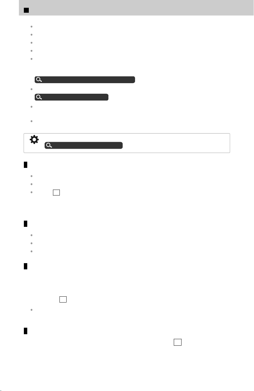
Securely attach the hitch, safety chains, and other necessary parts to the trailer.
Securely store all the items in and on the trailer so that they do not shift while driving.
Check if the lights and brakes on the trailer are working properly.
Check the pressure of the trailer tires, including the spare.
Turn off the Auto Idle Stop system using the Auto Idle Stop OFF button. The trailer weight
can affect your vehicle’s brake effectiveness if Auto Idle Stop is activated on a hill while
towing a trailer.
Auto Idle Stop System ON/OFF
u
P.162
Select TOW mode for optimized transmission operation when towing a trailer.
Drive Mode System
u
P.159
If TOW mode is not selected, turn off the rear parking sensor system through the rear
sensor setting. It may alert if it detects the towed object as an obstacle.
If TOW mode is not selected, turn off the rear Low Speed Braking Control through the rear
sensor setting. It may activate if it detects the towed object as an obstacle.
To set the Rear Sensor setting, refer to the following:
Customized Features
u
P.239
Towing speeds and gears
Drive slower than normal.
Obey posted speed limits for vehicles with trailers.
Use the D position when towing a trailer on level roads.
When towing a fix
ed-sided trailer (e.g., camper), do not exceed 55 mph (88 km/h).
At higher speeds, the trailer may sway or affect vehicle handling.
Turning and braking
Turn more slowly and with a wider turning arc than normal.
Allow more time and distance for braking.
Do not brake or turn suddenly.
Driving in hilly terrain
Monitor your temperature gauge. If it nears the red (H) mark
, turn off the climate
control system and reduce speed. Pull to the side of the road safely to cool down
the engine if necessary.
≫
Shift to the S position if the transmission shifts frequently.
If the automatic transmission fluid temperature exceeds the specified limit, the
transmission will also automatically up shift, even in the sequential shift mode.
Retrieving a boat
When retrieving a boat from the water, the sequential mode S
is recommended
to utilize the transmission lower gears.
1
Before Driving > Towing a Trailer
102

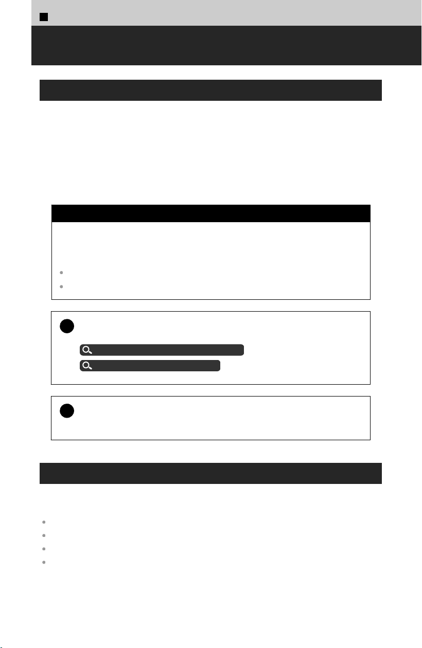
1
Before Driving >
Off-Highway Driving Guidelines
General Information
Your vehicle has been designed primarily for use on pavement; however, its higher
gr
ound clearance allows you to occasionally travel on unpaved roads. It is not
designed for trail-blazing, or other challenging off-highway activities.
If you decide to drive on unpaved roads, you will find that it requires somewhat
different driving skills and that your vehicle will handle somewhat differently than it
does on pavement. Pay attention to the precautions and tips in this section, and get
acquainted with your vehicle before leaving the pavement.
3 WARNING
Improperly operating this vehicle on or off-pavement can cause a crash or
r
ollover in which you and your passengers could be seriously injured or
killed.
Follow all instructions and guidelines in this owner’s manual.
Keep your speed low, and don’t drive faster than conditions permit.
!
Failure to operate your vehicle correctly might result in a crash or a
r
ollover.
Important Handling Information
u
P.15
Precautions While Driving
u
P.19
!
Be careful not to spin the tires excessively. This may damage the
int
elligent variable torque management (i-VTM4™) AWD system.
Important Safety Precautions
To avoid loss of control or rollover, be sure to follow all precautions and
r
ecommendations:
Be sure to store cargo properly and do not exceed your cargo load limits.
Whenever you drive, make sure you and your passengers always wear seat belts.
Keep your speed low, and never go faster than the conditions allow.
It’s up to you to continually assess the situation and drive within the limits.
104
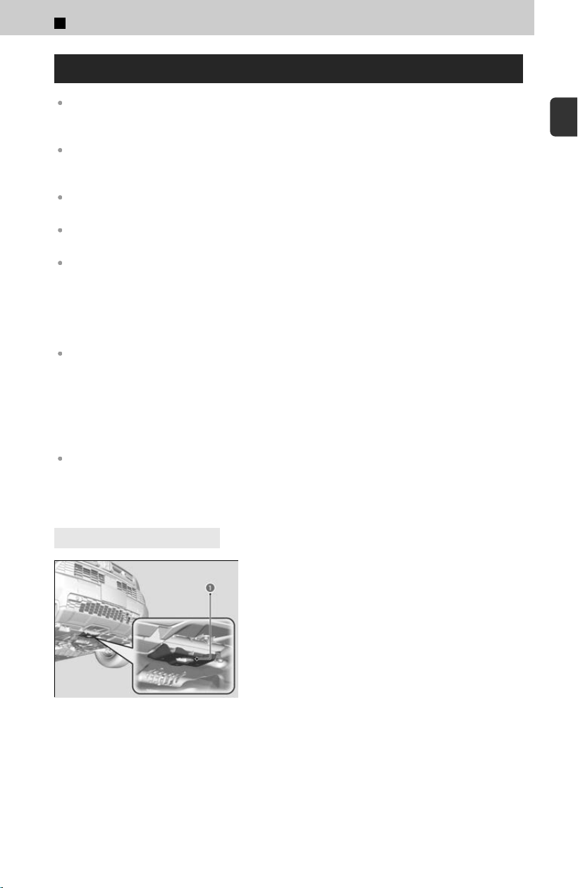
Avoiding Trouble
Check Out Your Vehicle before you leave the pavement and make sure that all scheduled
maintenance has been completed. Pay special attention to the condition of the tires, and
check the tire pressures.
Remember the route you choose presents limits (too steep or bumpy), you have limits
(driving skill and comfort), and your vehicle has limits (traction, stability, and power). Failing to
recognize these limits will likely put you and your passengers in a hazardous situation.
Accelerating and Braking should be done slowly and gradually. Trying to start or stop too
fast can cause a loss of traction and you could lose control.
Avoiding Obstacles and Debris in the road reduces the likelihood of a rollover or damage to
your suspension or other components.
Driving on Slopes increases your risk of a rollover, particularly if you attempt to drive across a
slope that is too steep. Going straight up or down a slope is usually the safest. If you can’t
clearly see all conditions or obstacles on a slope, walk it before you drive it. If there is any
doubt whether you can safely pass, don’t try it. Find another route. If you get stuck when
climbing, do not try to turn around. Back down slowly following the same route you took up
the hill.
Crossing a Stream - Avoid driving through deep water. If you encounter water in your route (a
small stream or large puddle, for example), evaluate it carefully before going ahead. Make
sure it is shallow, flowing slowly, and has firm ground underneath. If you are not sure of the
depth or the ground, turn around and find another route. Driving through deep water can also
damage your vehicle. When driving in water that reaches around half of the wheel height,
water can get into the transmission and differential, diluting the lubricant and causing an
eventual failure. It can also wash the grease out of the wheel bearings.
If You Get Stuck, carefully go in the direction that you think will get you unstuck. Do not spin
the tires as this will only make things worse and could damage the transmission. If you are
unable to free yourself, your vehicle will need to be towed. Front recovery hooks
*
and rear
recovery hook
*
are provided for this purpose.
4
Models with trailer hitch
a Front central recovery hook
The front central recovery hook is located by the
underside o
f the front bumper.
*: Not available on all models
1
Before Driving > Off-Highway Driving Guidelines
105
1
Before Driving
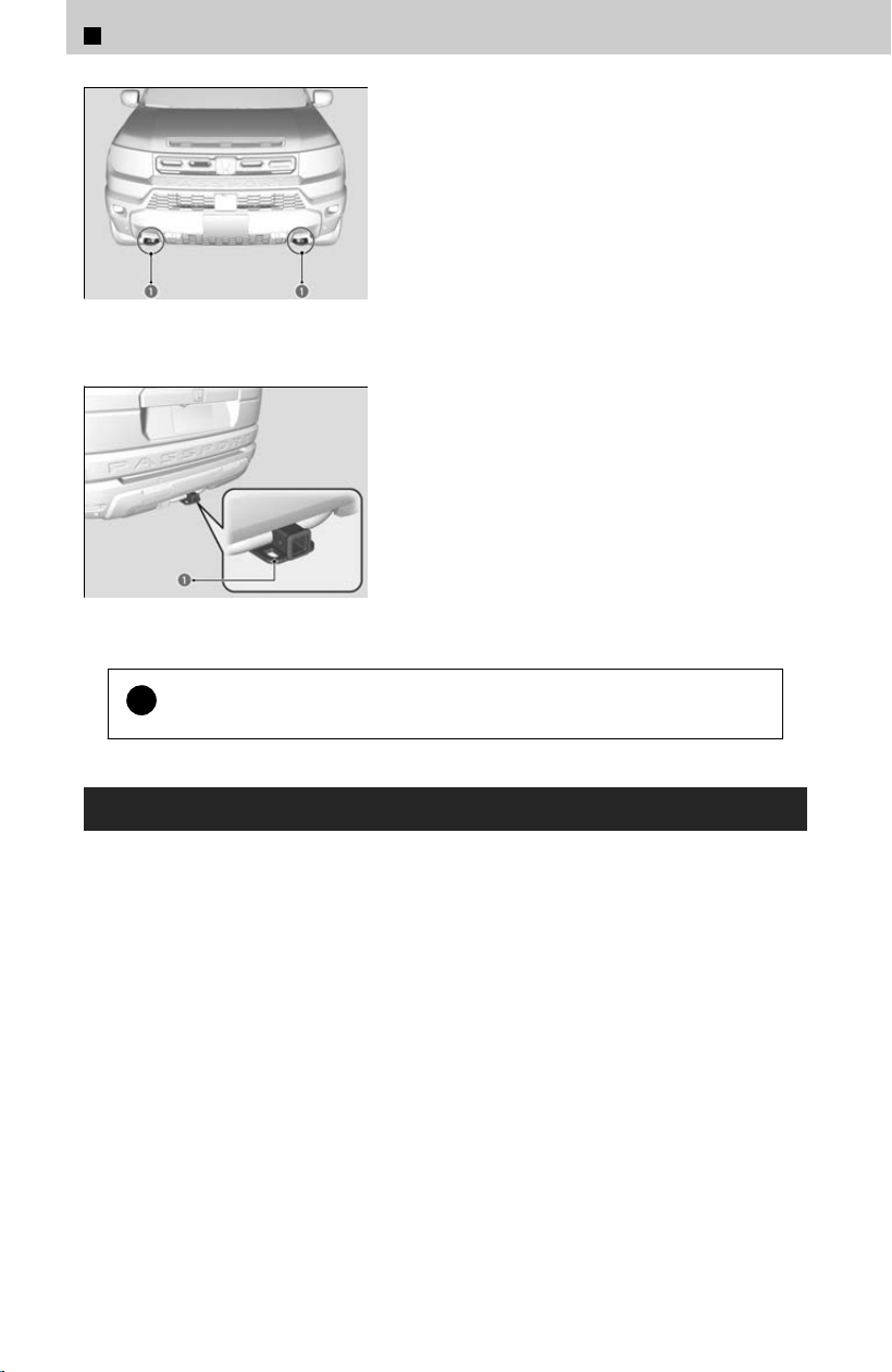
a Front outboard recovery
hooks
The front outboard recovery hooks are located
underneath the fr
ont bumper.
a Rear recovery hook
Trailer Hitch safety chain loops and receiver are
r
ated for off-road recovery.
!
Do not use recovery hooks for tow truck hookup or highway towing.
Off-Highway Driving
Your vehicle is designed, built, and equipped with systems and features to provide
y
ou with exceptional driving performance off-highway. However, due to the risks to
both you and other road users, including the risk of injury or death from loss of control
or crash, if you engage in off-highway driving, it is important to take precautions
before doing so.
When driving off-highway, you should always obey the posted speed limits and other
traffic laws, reduce speed as needed for traffic and environmental conditions, and not
engage in driving behaviors that may create heightened risks for yourself and any
other off-highway users who may be present (even if you are unaware of them).
1
Before Driving > Off-Highway Driving Guidelines
106

Your vehicle’s TRAIL or SAND mode and other systems are designed for increased
performance off-highway. Use of these systems may delay the intervention of vehicle
safety systems designed to minimize the risk of a loss of traction or steering control,
and can cause your vehicle to handle differently than you might expect or would
experience under normal driving conditions on pavement. Use of these systems will
not make up for a lack of appropriate driver experience and skill, and will not allow
the driver to overcome risks created by:
A lack of proper vehicle maintenance
Less than ideal road conditions and/or unfamiliarity with the driving environment
Other traffic or off-highway users
Off-highway driving requires special skills, knowledge, and experience, as the safety
risk
s are greatly increased when the your vehicle is operated at its upper performance
abilities. As a responsible driver, you should not drive above your skill limits or
training, even if your vehicle’s performance levels would otherwise allow you to do so.
If you intend to engage in off-highway driving, Honda strongly recommends that:
You first obtain appropriate, professional training
Turn off any devices or systems that may distract you from the driving task
Off-highway driving in general, results in greater wear and tear on the vehicle. If your
v
ehicle is not in top condition or if certain components, such as the brakes or tires,
have undue wear, those components could experience a loss of performance, or fail,
when engaging in off-highway driving. Therefore, Honda highly recommends that you
undertake more proactive and frequent maintenance than that required under normal
use and have your vehicle inspected at an authorized dealer (and all necessary
repairs or adjustments made) before you engage in any off-highway driving. In
addition to any required maintenance, there are specific items and protocols that you
should pay special attention to before, during and after engaging in any off-highway
driving. Ultimately, the decision whether to engage in off-highway driving is yours, and
depending on your vehicle’s condition and prior usage, the items and protocols listed
below may or may not be sufficient to ensure a safe driving experience.
BEFORE DRIVING
Before off-highway driving, fill the engine oil up to the upper level.
Recommend starting with full fuel tank and not allowing fuel to drop below ¼ tank while
driving off-highway.
INSPECT YOUR VEHICLE
Driving off-highway can be hard on a vehicle. Before you leave the pavement, be sure
al
l scheduled maintenance and service has been carried out, and that you have
inspected your vehicle and each of its relevant components to make sure that it still is
in a safe operating condition (example: wheel lug bolt torque, skid plate
*
and/or under
body component damage, tire pressure, etc.). We recommend repeating the BEFORE
DRIVING protocol, and if any item shows excessive wear or appears to be in an
unusual condition, have it replaced, or exercise appropriate caution when driving and
see your authorized dealer.
For more information, please contact your authorized dealer, and/or Honda Customer
Ser
vice.
*: Not available on all models
1
Before Driving > Off-Highway Driving Guidelines
107
1
Before Driving

AFTER DRIVING
After off-highway driving, it is critical to allow your vehicle to properly cool down.
Check underneath your vehicle and each of its relevant components, including the skid
plates
*
, to make sure that it still is in a safe operating condition (example: wheel lug bolt
torque, tire pressure, skid plate
*
damage, dirt and debris accumulation on skids, and
suspension components, etc.). We recommend repeating the BEFORE DRIVING protocol, and
if any item shows excessive wear or appears to be in an unusual condition, have it replaced, or
exercise appropriate caution when driving and see your authorized dealer.
If dirt and debris has accumulated on skids, suspension components, etc., remove dirt and
debris accumulation from them.
If operated in dirty conditions, clean brakes of abrasion materials to prevent excessive wear
or/and unpredictable braking.
!
The vehicle warranty does not cover any damage or failure resulting
fr
om off-highway driving, crawling, competitive climbing of any sort
whatsoever, or use on an off-road course or similar-type venue. See
warranty book for details.
*: Not available on all models
1
Before Driving > Off-Highway Driving Guidelines
108

Starting or Stopping the Engine
ENGINE START/STOP Button・・・・・・・・・・・・・・・・・・ 110
Starting the Engine・・・・・・・・・・・・・・・・・・・・・・・・・・・・ 111
Stopping the Engine・・・・・・・・・・・・・・・・・・・・・・・・・・・ 112
Remote Engine Start・・・・・・・・・・・・・・・・・・・・・・・・・・・112
What to Do If・・・・・・・・・・・・・・・・・・・・・・・・・・・・・・・・・・ 114
Shifting
About Shift Operation ・・・・・・・・・・・・・・・・・・・・・・・・・ 115
Braking
Foot Brake・・・・・・・・・・・・・・・・・・・・・・・・・・・・・・・・・・・・・ 120
Parking Brake・・・・・・・・・・・・・・・・・・・・・・・・・・・・・・・・・・121
Automatic Brake Hold・・・・・・・・・・・・・・・・・・・・・・・・・ 123
Anti-lock Brake System (ABS)・・・・・・・・・・・・・・・・・ 126
What to Do If・・・・・・・・・・・・・・・・・・・・・・・・・・・・・・・・・・ 126
Starting and Driving
Starting to Drive・・・・・・・・・・・・・・・・・・・・・・・・・・・・・・・ 127
Parking Your Vehicle
When Stopped・・・・・・・・・・・・・・・・・・・・・・・・・・・・・・・・・129
Rear View Camera
*
About Rear View Camera・・・・・・・・・・・・・・・・・・・・・・ 130
Multi View Camera System
*
About Multi View Camera System・・・・・・・・・・・・・ 132
Using the Multi View Camera System・・・・・・・・・・135
Multi View Camera System Limitations・・・・・・・・ 139
Refueling
Fuel Information・・・・・・・・・・・・・・・・・・・・・・・・・・・・・・・141
How to Refuel・・・・・・・・・・・・・・・・・・・・・・・・・・・・・・・・・ 142
Fuel Economy and CO2 Emissions
Improving Fuel Economy and Reducing CO2
Emissions・・・・・・・・・・・・・・・・・・・・・・・・・・・・・・・・・・・・ 144
Turn Signals/Light Switches
Turn Signals・・・・・・・・・・・・・・・・・・・・・・・・・・・・・・・・・・・ 145
Headlights/Parking Lights・・・・・・・・・・・・・・・・・・・・・ 145
Wipers and Washers
Windshield Wiper/Washer・・・・・・・・・・・・・・・・・・・・・ 152
Rear Wiper/Washer・・・・・・・・・・・・・・・・・・・・・・・・・・・・155
What to Do If・・・・・・・・・・・・・・・・・・・・・・・・・・・・・・・・・・ 155
Defr
oster
Defrosting the Windshield and Windows・・・・・・ 156
What to Do If・・・・・・・・・・・・・・・・・・・・・・・・・・・・・・・・・・ 157
Heated Windshield Button
*
Heated Windshield Button・・・・・・・・・・・・・・・・・・・・・158
Driving Features
Drive Mode System・・・・・・・・・・・・・・・・・・・・・・・・・・・・ 159
Auto Idle Stop・・・・・・・・・・・・・・・・・・・・・・・・・・・・・・・・・ 161
Hill Descent Control System・・・・・・・・・・・・・・・・・・・ 164
Vehicle Stability Assist™ (VSA®), aka Electronic
Stability Control (ESC), System・・・・・・・・・・・・・・・166
Agile Handling Assist・・・・・・・・・・・・・・・・・・・・・・・・・・ 168
Intelligent Variable Torque Management (i-
VTM4™) AWD System・・・・・・・・・・・・・・・・・・・・・・・・ 168
Tire Pressure Monitoring System (TPMS) with Tire
Fill Assist・・・・・・・・・・・・・・・・・・・・・・・・・・・・・・・・・・・・・169
Tire Pressure Monitoring System (TPMS) -
Required Federal Explanation・・・・・・・・・・・・・・・・ 170
*: Not available on all models
Driving Operation
109
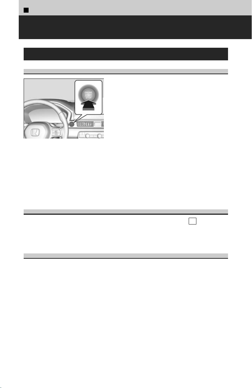
2
Driving Operation >
Starting or Stopping the Engine
ENGINE START/STOP Button
Changing the Power Mode
If you carry the keyless remote and press
ENGINE START/STOP button without depressing
the brake pedal, the power mode will change in
this order: VEHICLE
OFF➔ACCESSORY➔ON➔VEHICLE OFF.
VEHICLE OFF:
Vehicle power is turned OFF.
ACCESSORY:
The audio system and some accessories can be
used.
ON:
All accessories can be used.
If the keyless remote is set in a storage box or another place where its signal can be
int
errupted, the power mode may not change.
Automatic Power Off
If you leave the vehicle for 30 to 60 minutes with the transmission in P
and the
power mode in ACCESSORY, the vehicle automatically goes into the mode similar to
VEHICLE OFF (LOCK) to avoid draining the 12-volt battery.
Power Mode Reminder
If you open the driver’s door when the power mode is set to ACCESSORY, a warning
beep sounds
.
110
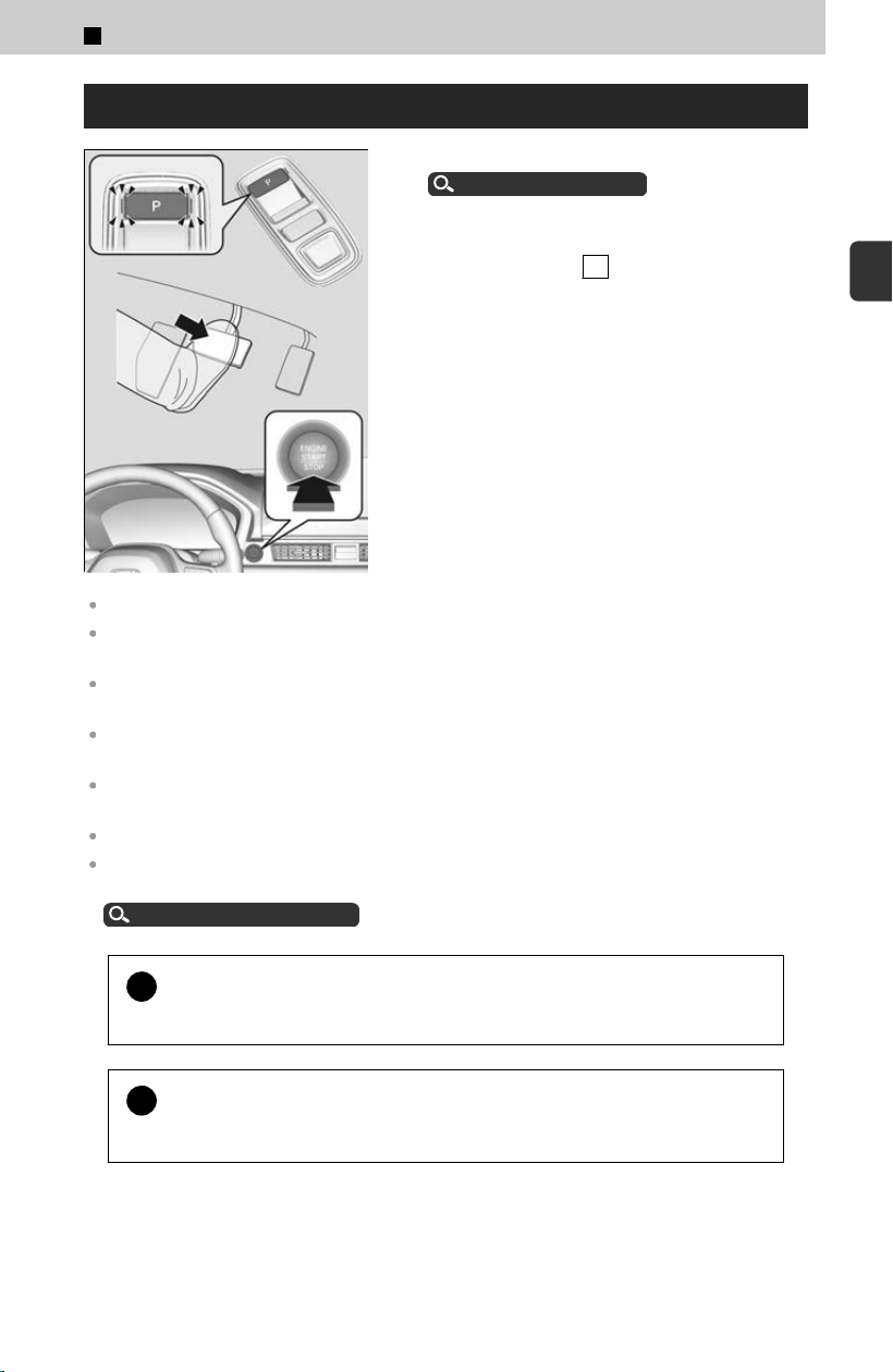
Starting the Engine
[1] Make sure the parking brake is applied.
Parking Brake
u
P.121
[2] Depress the brake pedal, then press the
ENGINE S
TART/STOP button while the
transmission is in P .
Keep your foot firmly on the brake pedal when starting the engine.
The engine is harder to start in cold weather and in thinner air found at altitudes above 8,000
feet (2,400 meters).
When starting the engine in cold weather, turn off all electrical accessories such as the lights,
climate control system, and rear defogger in order to reduce the 12-volt battery drain.
If you live in a region where winter is extremely cold, an engine block heater will improve
starting and warming of the engine. Consult a dealer for details.
Do not hold the ENGINE START/STOP button to start the engine. If the engine does not start,
wait at least 30 seconds before starting the engine again.
The engine may not start if the keyless remote is subjected to strong radio waves.
The immobilizer system protects your vehicle from theft. If an improperly coded device is
used, the engine’s fuel system is disabled.
Immobilizer System
u
P.48
!
Do not select a shift button while pressing the accelerator pedal.
Y
ou could damage the transmission.
!
To prevent unexpected accidents, do not depress the accelerator
pedal when turning on the engine
.
2
Driving Operation > Starting or Stopping the Engine
111
2
Driving Operation
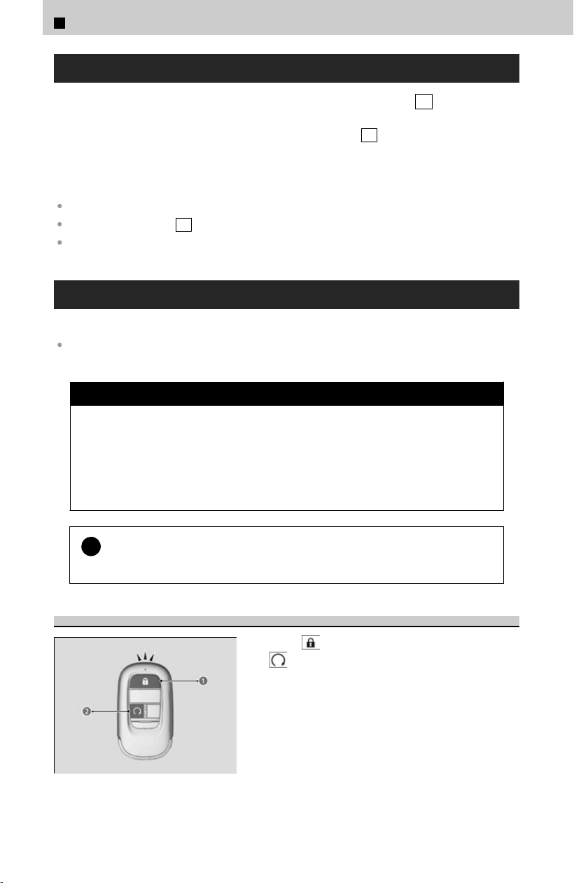
Stopping the Engine
While the vehicle is completely stopped, put the transmission into P
, then press the
ENGINE START/STOP button.
≫
Do not release the brake pedal until you have confirmed that P is shown on the shift
position indicator.
The power mode will automatically turn to VEHICLE OFF about 20 minutes after the
f
ollowing conditions have been met:
A door has been opened, such as when leaving the vehicle.
The transmission is in P .
The driver’s seat belt is not fastened.
Remote Engine Start
You can remotely start the engine using the keyless remote.
If there are buildings and obstacles between your vehicle and the remote, the range will be
reduced. This distance may vary by external electrical interference.
3 WARNING
Carbon monoxide gas is toxic and can rapidly accumulate in closed or even
par
tly enclosed areas. Breathing it can cause unconsciousness and even kill
you.
Never use the remote engine starter with the vehicle parked in a garage or
other areas with limited ventilation.
!
Before using the remote engine start, check your local laws.
The r
emote engine start may violate local laws.
To Start the Engine
Press the button (a), then press and hold
the
button (b).
≫
Some exterior lights flash once.
≫
If the engine starts successfully, some exterior lights
flash six times.
≫
If the engine does not start, exterior lights will not
flash. Go within the range, and try again.
2
Driving Operation > Starting or Stopping the Engine
112
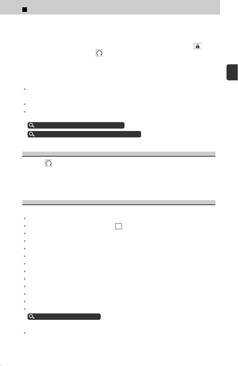
When started remotely, the engine automatically shuts off after 10 minutes of idling
and/or the brake pedal and ENGINE START/STOP button have not been pressed
simultaneously.
To extend the run time for another 10 minutes during the first run, press the
button, then press and hold the button.
≫
Some exterior lights flash six times if a 10-minute extension request was transmitted
successfully.
While the engine is running, the vehicle will automatically precondition the interior.
When it is warm outside:
The climate control system is activated in recirculation mode.
When it is cold outside:
The defroster is activated at a moderately warm temperature.
The rear defogger, heated door mirrors, front seat heaters, and heated steering wheel
*
are
activated.
Using the Heated Steering Wheel
u
P.190
Using the Front Seat Heaters/Ventilators
*
u
P.188
To Stop the Engine
Press the
button for one second.
≫
If the engine stop successfully, the exterior lights flash once.
≫
When the keyless remote is out of the keyless access system range, the exterior lights will not
flash. The engine will not stop. Go within the range, and try again.
Remote Engine Start Limitations
The engine may not start by the remote engine start if:
The power mode is not in VEHICLE OFF.
The transmission is in a position other than P .
The hood is open, or any door or the tailgate is unlocked.
You have already used the keyless remote twice to start the engine.
Another registered keyless remote is in the vehicle.
There is any antenna failure.
The door is unlocked with the built-in key.
The engine oil pressure is low.
The engine coolant temperature is extremely high.
The telematics unit malfunctions.
The security system alarm is not set.
The 12-volt battery charge is too low.
You have disabled a remote engine start setting.
Customized Features
u
P.239
The engine may stop while it is running if:
You do not start the vehicle within 10 minutes of starting the engine with the keyless remote.
*: Not available on all models
2
Driving Operation > Starting or Stopping the Engine
113
2
Driving Operation

The engine is stopped by using the keyless remote.
The security system alarm is not set.
The door is unlocked with the built-in key.
The hood is open, or any door or the tailgate is unlocked.
The transmission is in a position other than P .
The engine coolant temperature is extremely high.
The 12-volt battery is low.
The engine oil pressure is low.
The malfunction indicator lamp comes on if there is a problem with the emissions control
systems.
What to Do If
If the keyless remote battery is weak
Bring the keyless remote close to the ENGINE S
TART/STOP button if the battery in
the keyless remote is weak.
If the Keyless Remote Battery is Weak
u
P.396
Why does the engine not start?
A pre-registered key is required.
Immobilizer system
u
P.48
If the keyless remote is set on the instrument panel, in a storage box, or another
plac
e where its signal can be interrupted, the power mode may not change.
Why does the brake pedal sink down slightly when the engine is
started?
This is related to the activation of the electric brake system, and it is normal.
Why does the exhaust system sound abnormal, or why is there an
exhaust gas or gasoline smell in the vehicle?
There may be a problem with the engine or exhaust system. Have your vehicle
check
ed by a dealer.
Why is a motor sound coming from under the hood?
Immediately after starting the engine or while driving, you may hear a motor sound
c
oming from under the hood due to a system check.
2
Driving Operation > Starting or Stopping the Engine
114
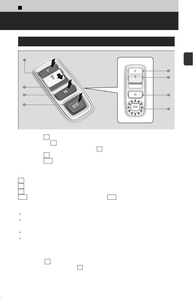
2
Driving Operation >
Shifting
About Shift Operation
a Press the P button.
b Pull back the R
button.
≫
The beeper sounds once when you change to R .
c P
ress the N button.
d Press the D/S
button.
≫
Each time you press the button, the mode switches between Drive and S Position mode.
e Shift But
ton Indicator
P
Park: Used when parking or starting the engine.
R Reverse: Used when reversing.
N Neutral: Transmission is not locked.
D/S Drive/S Position: Each time you press the D/S button, the mode switches
between Drive and S Position mode.
Drive is used for:
Normal driving (gears change between 1st and 10th automatically)
Temporarily driving in the sequential mode.
S Position is used for:
Automatically changing gears between 1st and 8th (8th gear is used only at high speed).
Driving in the sequential mode.
Precautions when parking:
Park your vehicle in a safe place with the power mode in ON, then apply the brakes
and pr
ess the P button to put the transmission in Park.
≫
The indicators on the sides of the P button come on.
115
2
Driving Operation
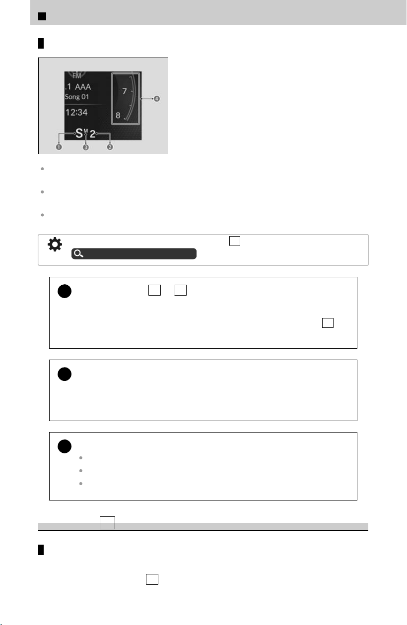
Gauge display
a Gear Position Indicator (Transmission
System Indicator)
b Sequential Mode Gear Selection Indicator
c M (sequential mode) Indicator
d Tachometer Red Zone
Use the gear position indicator and the shift button indicator to check the shift position before
and after selecting a shift button.
The fuel supply may be cut off if you drive at engine speeds in or over the tachometer red
zone (engine speed limit). If this happens, you may experience a slight jolt.
When shifting gears in extremely low temperatures (-22°F/-30°C), there may be a short delay
before the shift position is displayed.
The beeper sounds once when you change to R .
Customized Features
u
P.239
!
When you change D
to R and vice versa, depress the brake pedal
to come to a complete stop, then select the intended shift position
while maintaining brake pressure.
Always keep your foot on the brake pedal until you have confirmed that P
is
shown on the gear position indicator.
!
If the transmission system indicator blinks when driving, in any shift
position, ther
e is a problem with the transmission.
Avoid sudden acceleration and have the transmission checked by a dealer as
soon as possible.
!
To prevent malfunction and unintended engagement:
Do not spill any liquids on or around shift buttons.
Do not place or drop any objects on or around shift buttons.
Do not let passengers or children operate the shift buttons.
Automatic P Position Function
When opening the driver’s door
If you open the driver’s door under the following conditions, the shift position
aut
omatically changes to P .
2
Driving Operation > Shifting
116
The vehicle is stationary with the engine running, or moving at 1 mph (2 km/h) or slower.
The transmission is in a position other than P .
You have unfastened the driver side seat belt.
≫
If you manually change the shift position from P with the brake pedal depressed, the
shift position will automatically return to P
once you release the brake pedal.
!
The system will automatically shift to P
when the conditions are
met, but in the interest of safety, you should always put the shift
position in P before opening the driver’s door when parking.
When Stopped
u
P.129
!
If you want to drive the vehicle after the shift position has
aut
omatically changed to P under the described conditions, close
the door, fasten the seat belt, depress the brake pedal, then change
the shift position. If you leave the vehicle, turn off the engine and lock
the doors.
When turning off the power mode
If you turn the engine off while the vehicle is stationary, and the transmission is in a
position other than P
, the shift position automatically changes to P .
N Position Holding Mode (Car Wash Mode)
With the engine running:
[1] Press and hold the brake pedal.
[
2] Select N , then release the button to display (Neutral) N hold mode on the
driver information interface.
[3] Press and hold N again for two seconds.
≫
This puts the vehicle in car wash mode which must be used when your vehicle is pulled
through a conveyor type automatic car wash where you or an attendant does not remain
in the vehicle.
If the ENGINE S
TART/STOP button is pressed after car wash mode has been
activated, the power mode will change to ACCESSORY and a message will be
displayed on the driver information interface.
≫
For 15 minutes the shift position remains in N with the power mode in ACCESSORY. After
that, the position automatically changes to P
and the power mode changes to OFF.
≫
Manually changing to P cancels ACCESSORY mode. The P indicator comes on and the
power mode changes to OFF. You must always shift to P
when car wash mode is no longer
needed.
2
Driving Operation > Shifting
117
2
Driving Operation
!
Note that the transmission may not stay in N
position while any of
the following indicators is on:
Transmission system indicator.
Malfunction indicator lamp.
Charging system indicator.
Restrictions on Selecting a Shift Position
You cannot select a shift position under certain circumstances that may lead to a
cr
ash.
≫
When in a safe condition, select the appropriate shift position with the vehicle is stopped and
depressing the brake pedal.
When the
tr
ansmission is in:
1. Under these circumstances:
2. If you try to
change to the
following:
3. The shift
position
remains in/
changes to:
P
The brake pedal is not depressed.
Other shift position P
The accelerator pedal is
depressed.
N
The vehicle is moving at low speed
without the brake pedal depressed.
Other shift position N
The vehicle is moving at low speed
with the accelerator pedal
depressed.
N
, D , or S The vehicle is moving forward. R N
R or N The vehicle is moving backward. D , S N
R , N , D , or S The vehicle is moving. P N
Sequential Mode
Use the paddle shifters to change between 1st and 10th gears without removing your
hands fr
om the steering wheel. The transmission will switch to the sequential mode.
≫
The sequential mode may be canceled if the drive mode is changed.
Sequential Mode Operation
Each paddle shift operation makes a single or double gear change. To change gears
c
ontinuously, release the paddle shifter before pulling it again for the next gear.
2
Driving Operation > Shifting
118
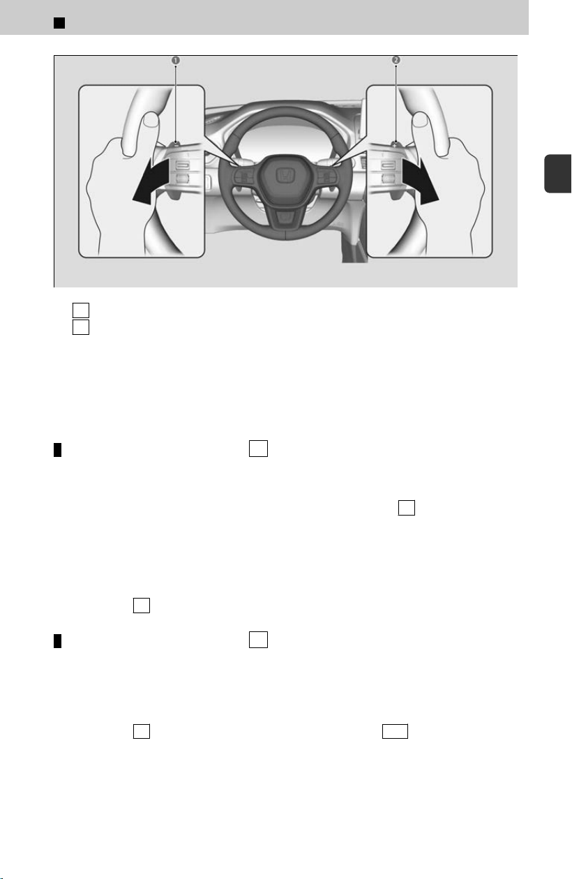
a - Paddle Shifter: Shift down (Changes to a lower gear)
b +
Paddle Shifter: Shift up (Changes to a higher gear)
If the sequential mode gear selection indicator blinks when you try to shift up or
do
wn, this means your vehicle speed is not in its allowable gear range or the
protection of transmission system is necessary.
Slightly accelerate to shift up and decelerate to shift down while the indicator is
blinking.
When the Transmission is in D :
The vehicle will go into the sequential mode momentarily, and the sequential mode
g
ear selection indicator will come on.
When the vehicle goes into the sequential mode by using the - paddle shifter and
the lower gear is available, the transmission properly selects single or double gear
change.
Once the vehicle starts traveling at constant speed or accelerates, the sequential
mode will be automatically turned off, and the sequential mode gear selection
indicator will go off.
Holding the + paddle shifter for two seconds will cancel this mode.
When the Transmission is in S :
The vehicle will go into the sequential mode, and the M (sequential mode) indicat
or
and sequential mode gear selection indicator will come on.
If the vehicle speed increases and the engine speed reaches near the tachometer
red zone, the transmission automatically shifts up to the next gear.
Holding the + paddle shifter for two seconds or pushing D/S button will cancel
this mode. When the sequential mode is canceled, the sequential mode indicator
and sequential mode gear selection indicator go off.
2
Driving Operation > Shifting
119
2
Driving Operation
2
Driving Operation >
Braking
Foot Brake
The foot brake is used to slow down or stop your vehicle. It is operated by a brake
pedal
.
!
Check the brakes after driving through deep water, or if there is a
buildup o
f road surface water. If necessary, dry the brakes by lightly
depressing the pedal several times.
!
If you hear a continuous metallic friction sound when applying the
br
akes, this is caused by the brake wear indicator rubbing on the brake
rotor and indicates that the brake pads need to be replaced. Have your
vehicle checked by a dealer. If you hear only an occasional squeak or
squeal when you initially apply the brake pedal, this may be normal
and caused by high frequency vibration of the brake pads against the
rotating brake disc.
!
Do not constantly depress the brake pedal while going downhill, as it
builds up heat
.
If you constantly depress the brake pedal while going downhill, it will build up
heat, which reduces the brake effectiveness. Apply engine braking by taking
your foot off the accelerator pedal and downshifting to a speed position.
!
Whenever the brakes are activated by CMBS™ or another system that
aut
omatically controls braking, the brake pedal is depressed and
released in accordance with braking function.
Brake Assist System
Designed to assist the driver by generating greater braking force when you depress
the br
ake pedal hard during emergency braking. Press the brake pedal firmly for more
powerful braking.
≫
When brake assist operates, the pedal may wiggle slightly and an operating noise may be
heard.
120
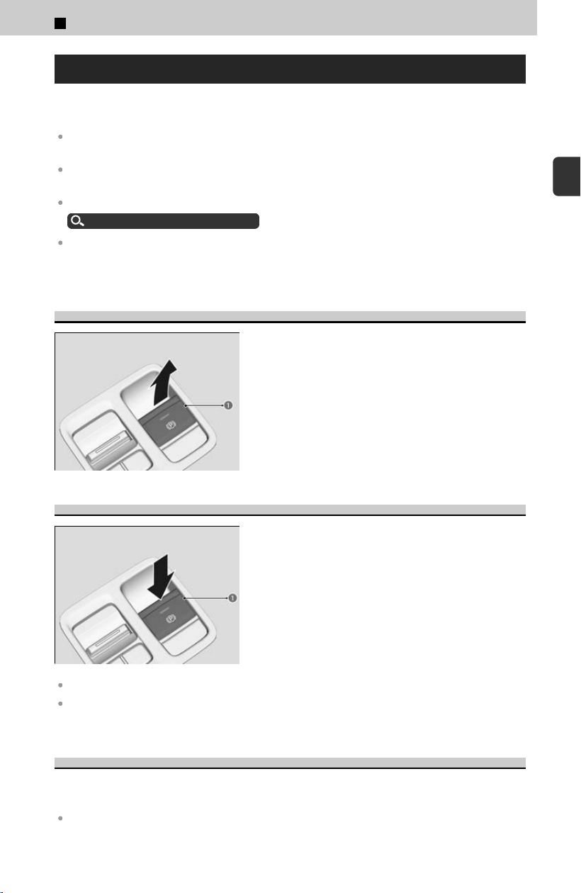
Parking Brake
Use the parking brake to keep the vehicle stationary when parked. When the parking
br
ake is applied, you can manually or automatically release it.
You may hear the electric parking brake system motor operating from the rear wheel area
when you apply or release the parking brake. This is normal.
The brake pedal may slightly move due to the electric parking brake system operation when
you apply or release the parking brake. This is normal.
You cannot apply or release the parking brake if the 12-volt battery goes dead.
Emergency Engine Start
u
P.396
If you pull up and hold the electric parking brake switch while driving, the brakes on all four
wheels are applied by the VSA® system until the vehicle comes to a stop. The electric parking
brake then applies, and the switch should be released.
To apply
The electric parking brake can be applied any
time the vehicle has battery, no matter which
position the power mode is in. Pull the electric
parking brake switch (a) up gently and securely.
≫
The indicator in the switch comes on.
≫
The parking brake and brake system indicator (red)
comes on for 30 seconds.
To release
Depress the brake pedal, then press the electric
parking brake switch (a).
≫
The indicator in the switch goes off.
≫
The parking brake and brake system indicator (red)
goes off.
The power mode must be in ON in order to release the electric parking brake.
Manually releasing the parking brake using the switch helps your vehicle start slowly and
smoothly when facing downhill on steep hills.
Automatic Parking Brake Feature
The parking brake is applied automatically when you set the power mode to VEHICLE
OFF
.
The default setting for this feature is OFF.
2
Driving Operation > Braking
121
2
Driving Operation

Activating and deactivating the automatic parking brake feature
With the power mode is in ON, carry out the following steps to either activate or
deactiv
ate the automatic parking brake feature.
[1] Put the transmission into P
.
[2] Without depressing the brake pedal, pull up the electric parking brake switch.
≫
Check that the parking brake and brake system indicator (red) has come on.
[3] Pull up and hold the electric parking brake switch. When you hear a beeping
sound, r
elease the switch and within three seconds pull up and hold the
switch again.
[4] When you hear a sound indicating that the procedure is completed, release
the switch.
≫
Two beeps indicate that the feature has been activated.
≫
One beep indicates that the feature has been deactivated.
≫
To confirm that the parking brake is applied, check if the parking brake and brake
system indicator (red) is on.
In the following situations, the parking brake automatically operates.
When the vehicle stops for more than 10 minutes while ACC with Low Speed Follow is
activated.
When the driver’s seat belt is unfastened while your vehicle is stopped automatically by
ACC with Low Speed Follow.
When the engine is turned off, except by Auto Idle Stop system, while ACC with Low Speed
Follow is activated.
When the vehicle stops with the automatic brake hold system activated for more than 10
minutes.
When the driver’s seat belt is unfastened while your vehicle is stopped and the brake hold
is applied.
When the engine is turned off, except by Auto Idle Stop system, while the brake hold is
applied.
When there is a problem with the Brake Hold System while brake hold is applied.
!
In cold climates, the parking brake may freeze in place if applied.
When parking the v
ehicle, chock the wheels and make sure the
automatic parking brake feature is deactivated. Also, when putting
your vehicle through a conveyor-type car wash or when having your
vehicle towed, deactivate the automatic parking brake feature and
leave the parking brake released.
2
Driving Operation > Braking
122
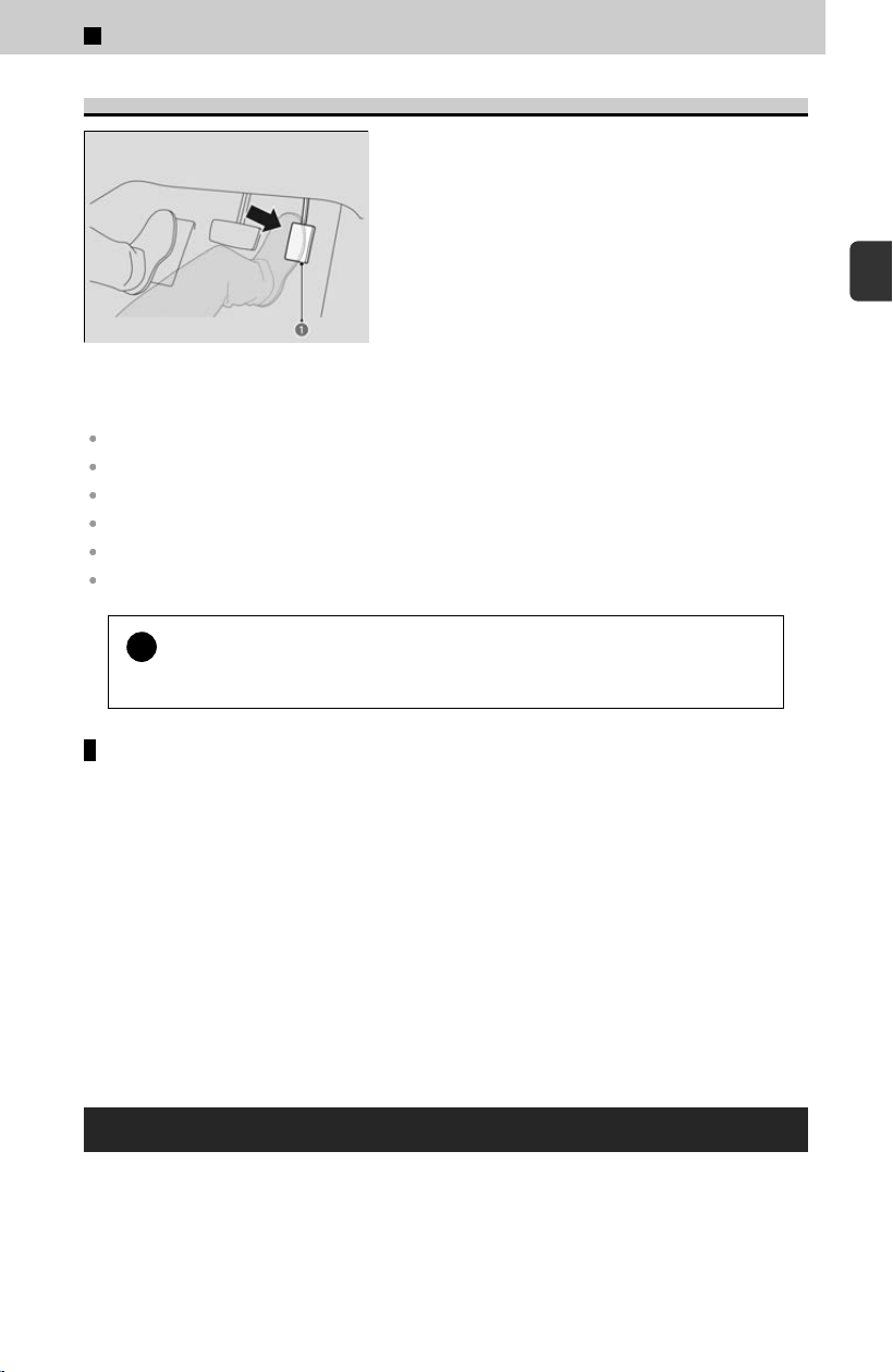
To Release Automatically
Depress the accelerator pedal (a), to start the
vehicle.
≫
Parking brake and brake system indicator (red) goes
off.
The parking brake may not be released automatically while the following indicators
ar
e on:
Malfunction indicator lamp
Transmission system indicator
Parking brake and brake system indicator (amber)
Vehicle Stability Assist™ (VSA®) System indicator
Anti-lock Brake System (ABS) indicator
Supplemental restraint system indicator
!
If the driver’s seat belt is unfastened, the parking brake will not
r
elease automatically.
Temporarily deactivate the automatic parking brake feature
If you need to temporarily deactivate the feature for when putting your vehicle
thr
ough a conveyor type car wash or when having your vehicle towed, follow the
procedure explained below.
[1] Depress the brake pedal and bring the vehicle to a stop.
[
2] Set the power mode to VEHICLE OFF and then within two seconds push down
the electric parking brake switch.
≫
Activation and deactivation settings for the feature will not be affected.
≫
Before temporarily deactivating the feature, make sure to first turn off both Adaptive
Cruise Control (ACC) with Low Speed Follow and the automatic brake hold system.
≫
To confirm that the parking brake is applied, check if the parking brake and brake
system indicator (red) is on.
Automatic Brake Hold
Keeps the brake applied after releasing the brake pedal until the accelerator pedal is
pr
essed. You can use this system while the vehicle is temporarily stopped, like at
traffic lights and in heavy traffic.
2
Driving Operation > Braking
123
2
Driving Operation
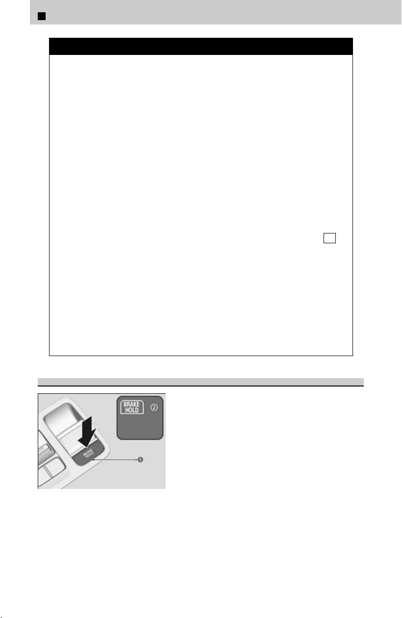
3 WARNING
Activating the automatic brake hold system on steep hills or slippery roads
may s
till allow the vehicle to move if you remove your foot from the brake
pedal.
If a vehicle unexpectedly moves, it may cause a crash resulting in serious
injury or death.
Never activate the automatic brake hold system or rely on it to keep a
vehicle from moving when stopped on a steep hill or slippery roads.
Using the automatic brake hold system to park the vehicle may result in the
vehicle unexpectedly moving.
If a vehicle moves unexpectedly, it may cause a crash, resulting in serious
injury or death.
Never leave the vehicle when braking is temporarily kept by automatic
brake hold and always park the vehicle by putting the transmission in P
and applying the parking brake.
When using the automatic brake hold, keep your foot on the brake pedal
until the automatic brake hold indicator comes on.
If the vehicle unexpectedly moves, it may cause a crash resulting in serious
injury or death.
Release your foot from the brake pedal after the automatic brake hold
indicator comes on.
Turning on the System
[1] Fasten your seat belt properly, then start the
engine. Press the automatic brake hold
button (a).
≫
The automatic brake hold system indicator (b)
comes on, and then the system goes into
standby mode.
2
Driving Operation > Braking
124
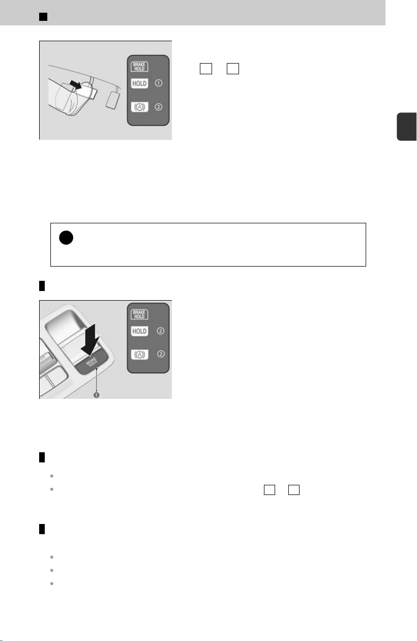
a U.S. models
b Canadian models
[2] Depress the brake pedal to come to a
c
omplete stop while the transmission into
D or S .
≫
The automatic brake hold indicator (a/b)
comes on, and then the automatic brake hold is
operates. Take your foot off the brake pedal.
≫
The automatic brake is held for up to 10
minutes.
The next time the engine is turned on, if the driver’s seat belt is fastened, the system
wil
l return to standby mode.
!
Make sure to turn off the automatic brake hold system before using an
aut
omated car wash.
System OFF
When you press the automatic brake hold button
(a), the system is turned off.
If the indicator (b) is lit up
, turn off the system
while depressing the brake pedal.
If the system is turned off, it will remain off the next time the power mode is started.
The system automatically cancels when:
You engage the parking brake.
You depress the brake pedal and put the transmission into P or R .
The system automatically cancels and the parking brake is applied
when:
Braking is kept for more than 10 minutes.
The driver’s seat belt is unfastened.
The engine is turned off.
2
Driving Operation > Braking
125
2
Driving Operation
There is a problem with automatic brake hold system.
Anti-lock Brake System (ABS)
Helps prevent the wheels from locking up while driving at 6 mph (10 km/h) or above,
and helps y
ou retain steering control by pumping the brakes rapidly, much faster than
you can.
≫
The electronic brake distribution (EBD) system, which is part of the ABS, also balances the
front-to-rear braking distribution according to vehicle loading.
≫
You should never pump the brake pedal. Let the ABS work for you by always keeping firm,
steady pressure on the brake pedal. This is sometimes referred to as “stomp and steer.”
The brake pedal may pulsate slightly when the ABS is working. Depress the brake
pedal and k
eep holding the pedal firmly down. On dry pavement, you will need to
press on the brake pedal very hard before the ABS activates. However, you may feel
the ABS activate immediately if you are trying to stop on snow or ice.
The ABS is not designed for the purpose of reducing the time or distance it takes for a vehicle
to stop: It is designed to limit brake lockup which can lead to skidding and loss of steering
control.
!
The ABS may not function correctly if you use a tire of the incorrect
siz
e or type.
!
If the ABS indicator comes on while driving, there may be a problem
with the s
ystem.
While normal braking will not be affected, there is a possibility that the ABS will
not be operating. Have your vehicle checked by a dealer immediately.
What to Do If
I hear a screeching sound when I depress the brake pedal. Why?
To satisfy the performance under a wide range of driving conditions, a high
per
formance braking system is equipped on your vehicle. You may hear the brake
squeal under certain conditions, such as vehicle speed, deceleration, humidity, and
so on.
2
Driving Operation > Braking
126
2
Driving Operation >
Starting and Driving
Starting to Drive
[1] Keeping your right foot on the brake pedal, select the shift position.
≫
If you started the engine with the remote engine start feature, depress the brake pedal
and press the ENGINE START/STOP button before changing the shift position.
[2] Gradually release the brake pedal and gently depress the accelerator pedal to
pul
l away.
≫
The parking brake will release automatically. You can also release it by operating the
parking brake switch.
Parking Brake
u
P.121
When the engine was started with remote engine start feature, the engine stops when
the shif
t position is taken out of P before the ENGINE START/STOP button is
pressed.
≫
To start driving, restart the engine and follow step 1.
Starting the Engine
u
P.111
!
If the power mode is set to ACCESSORY while driving, the engine will
shut do
wn and all steering and brake power assist functions will stop,
making it difficult to control the vehicle.
!
Do not select N
while driving as you will lose engine braking (and
acceleration) performance.
!
During the firs
t 600 miles (1,000 km) of operation, avoid sudden
acceleration or full throttle operation so as not to damage the engine
or powertrain.
!
Avoid hard braking for the firs
t 200 miles (300 km) after purchasing
your new vehicle or replacing the brake pads or rotors, to allow for
proper break-in.
Hill Start Assist System
Hill start assist keeps the brake engaged briefly to help prevent the vehicle from
r
olling on inclines as you move your foot from the brake pedal to the accelerator.
127
2
Driving Operation
Put the transmission into D or S when facing uphill, or R when facing downhill,
then release the brake pedal.
≫
Hill start assist may not prevent the vehicle from rolling downhill on a very steep or slippery
slope, and will not operate on small inclines.
≫
Hill start assist is not a replacement for the parking brake.
Automatic Transmission
Creeping
This vehicle creeps when the shift position is in D
, S , or R .
≫
Keep the brake pedal firmly depressed when stopped or ensure that brake-hold is engaged.
Automatic Brake Hold System
u
P.123
Kickdown
Quickly depressing the accelerator pedal while driving uphill may cause the
tr
ansmission to drop to a lower gear, unexpectedly increasing vehicle speed.
Depress the accelerator pedal carefully, especially on slippery roads and curves.
Driving Guidelines for Your Utility Vehicle
Utility vehicles have a significantl
y higher rollover rate than other types of vehicles. To
prevent rollovers or loss of control:
Take corners at slower speeds than you would with a passenger vehicle.
Avoid sharp turns and abrupt maneuvers whenever possible.
Do not modify your vehicle in any way that would raise its center of gravity.
Do not carry heavy cargo on the roof.
Failure to operate your vehicle correctly might result in a crash or a rollover.
Important Handling Information
u
P.15
Precautions While Driving
u
P.19
2
Driving Operation > Starting and Driving
128
2
Driving Operation >
Parking Your Vehicle
When Stopped
[1] Depress the brake pedal firml
y and come to a complete stop.
[2] With the brake pedal depressed, pull up the electric parking brake switch slowly,
but fully.
[3] Change the shift position to P .
≫
Do not release the brake pedal until you have confirmed that P is shown on the gear
position indicator.
3 CAUTION
The vehicle can roll away if left unattended without c
onfirming that Park is
engaged. A vehicle that rolls away could cause a crash resulting in serious
injury or death.
Always keep your foot on the brake pedal until you have confirmed that P
is shown on the gear position indicator.
!
Always set the parking brake, especially if you are parked on an incline.
!
The following may damage the driveline or cause the transmission to
o
verheat and fail:
Depressing the accelerator and brake pedals simultaneously.
Changing to P before the vehicle stops completely.
Bringing the vehicle to a stop while adjusting the accelerator pedal on an
incline.
!
Do not park your vehicle near flammable objects. Heat from the
e
xhaust can cause a fire.
!
In extremely cold temperatures, do not apply the parking brake but, if
parking on a slope
, either turn the front wheels so they will contact the
curb if the vehicle rolls down the slope or block the wheels to keep the
vehicle from moving.
129
2
Driving Operation
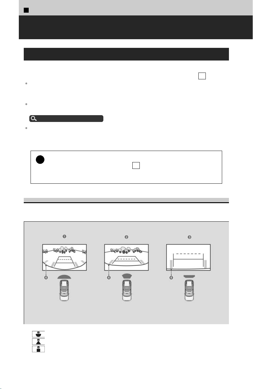
2
Driving Operation >
Rear View Camera
*
About Rear View Camera
The audio/information screen can display your vehicle’s rear view. The display
aut
omatically changes to the rear view when the transmission is put into R .
Visually confirm that it is safe to drive before backing up. Certain conditions (such as weather,
lighting, and high temperatures) may also restrict the rear view. Do not rely on the rearview
display which does not give you all information about conditions at the back of your vehicle.
If the rear camera lens is covered with dirt or moisture, activate the rearview camera washer
*
or use a soft, moist cloth to keep the lens clean and free of debris.
Rear Wiper/Washer
u
P.155
The camera view is restricted. You cannot see the corner ends of the bumper or what is
underneath the bumper. Its unique lens also makes objects appear closer or farther than they
actually are.
!
If the vehicle’s rear view is not displayed on the audio/information
scr
een while the shift position is in R , there may be a problem with
the system. Have your vehicle checked by a dealer immediately.
Switching Camera Modes
You can view three different camera modes on the screen. Select the appropriate icon
t
o switch the mode.
a Wide view mode
b
Normal view mode
c
Top down view mode
*: Not available on all models
130
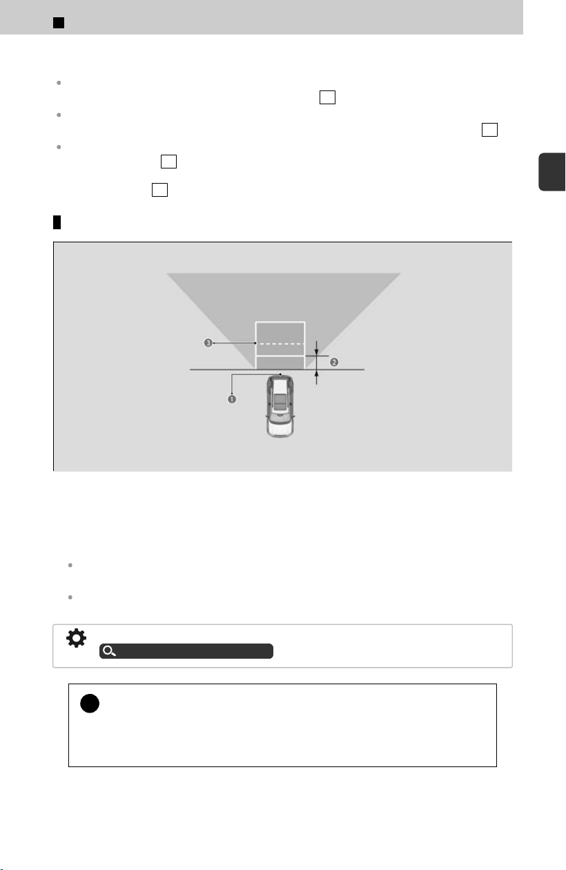
d Bumper
If you were last using Wide view mode or Normal view mode, the same view mode will be
activated the next time you put the transmission into R
.
If you were using Top down view mode before you turned off the engine, Wide view mode will
be activated the next time you set the power mode to ON and put the transmission into R
.
If you were using Top down view mode and 10 seconds elapsed after you took the
transmission out of R
, the view mode you were using just before selecting Top down view
mode (Wide view mode or Normal view mode) will be activated the next time you put the
transmission into R .
Distance between the vehicle and guideline
a Camera
b Approx. 19 inch (50 cm)
c Tailgate open range
The following can be displayed when the system is on:
Fixed Guideline: Helps you get a sense of a distance between your vehicle and the rear
surroundings.
Dynamic Guideline: Indicates vehicle direction while the steering wheel is in the current
position.
The guidelines can be turned on and off using the audio/information screen.
Customized Features
u
P.239
!
The guidelines should be used as a reference only.
The positions
/distances indicated by the guidelines and camera views on the
display may differ from the actual positions/distances due to the changes in the
vehicle height, road conditions, and other factors.
2
Driving Operation > Rear View Camera
*
131
2
Driving Operation

2
Driving Operation >
Multi View Camera System
*
About Multi View Camera System
The multi view camera system is a four camera system that views areas commonly
kno
wn as “blind spots” from different angles, then displays the images on the screen.
This system can be used to:
Check the right and left sides of the vehicle while crossing at intersections with poor visibility
(obstructed view, etc.).
Checking the Front of Your Vehicle
u
P.135
Check for obstacles in front of the vehicle when parking or maneuvering in confined areas.
Checking the Front of Your Vehicle
u
P.135
Checking the Sides of Your Vehicle
u
P.136
Check for obstacles when you are moving in R .
Checking for Obstacles at the Back of Your Vehicle
u
P.137
The multi view camera system does not eliminate all blind spots. The system is for your
convenience only.
Always keep the camera lenses clean and free from debris.
If the front or rear camera lens is covered with dirt or moisture, activate the frontview or
rearview camera washer or use a soft, moist cloth to keep the lens clean and free of debris.
Windshield Wipers/Washers
u
P.152
Rear Wiper/Washer
u
P.155
3 WARNING
Failure to visually assess the area around the vehicle (directly or by use of
the mirr
ors) may result in a crash causing serious injury or death.
The areas shown in the multi view camera system display are limited. The
display may not show all pedestrians or other objects around your vehicle.
Do not solely rely only on the multi view camera system display to assess
whether it is safe to move your vehicle.
Failure to pay proper attention to your surroundings while driving may
result in a crash causing serious injury or death.
To help mitigate the chances of a collision, only look at the multi view
camera system display when it is safe to do so.
*: Not available on all models
132
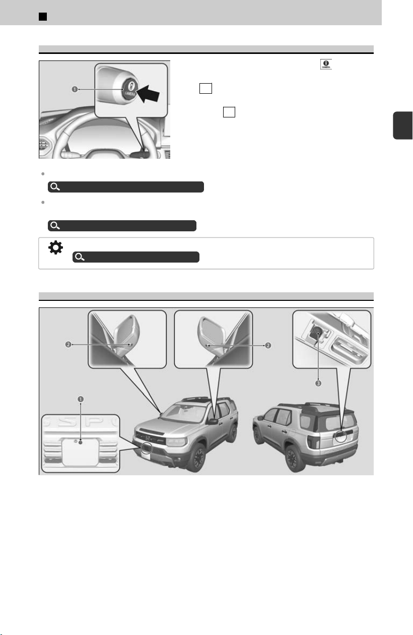
Displaying a Camera Image
To display frontal views: Press the button
(a) when the shift position is in a position other
than R
.
To display rear reviews: Change the shift
position to R when the vehicle is stationary.
When the parking sensors detect an obstacle, the indicator will appear on the screen.
About Parking Sensor System
u
P.318
The Cross Traffic Monitor system alerts you when a vehicle is approaching your vehicle from
the rear corner.
About Cross Traffic Monitor
u
P.314
You can customize the display setting.
Customized Features
u
P.239
Camera Locations and Images
a Front View Camera
b Side View Cameras
c Rear View Camera
The unique multi view camera lenses make distances appear differently than they
actual
ly are - objects seen on the screen may appear closer or further away, and may
be distorted. This becomes more apparent the further away an object is from your
vehicle.
2
Driving Operation > Multi View Camera System
*
133
2
Driving Operation
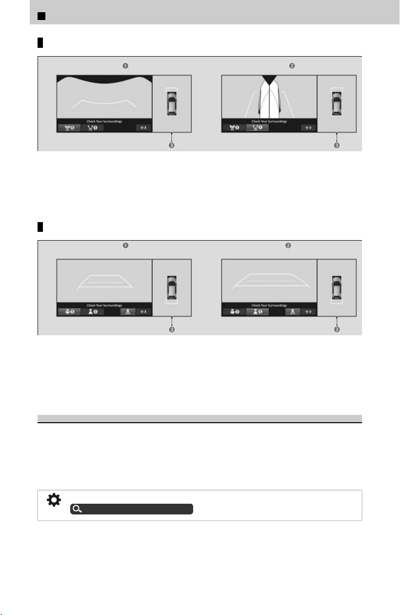
Front side display
a Front View + Ground View
b Left and Right Side View + Ground View
c Ground View: An overhead view created by the combination of images captured
by four cameras.
Rear side display
a Rear Wide View + Ground View
b Rear Normal View + Ground View
c Ground View: An overhead view created by the combination of images captured
by four cameras.
Reference Lines and Guides
The following can be displayed when the system is on:
Fixed Guideline: Helps y
ou get a sense of a distance between your vehicle and the
surroundings.
Dynamic Guideline: Indicates vehicle direction while the steering wheel is in the
current position.
The guidelines can be turned on and off using the audio/information screen.
Customized Features
u
P.239
2
Driving Operation > Multi View Camera System
*
134
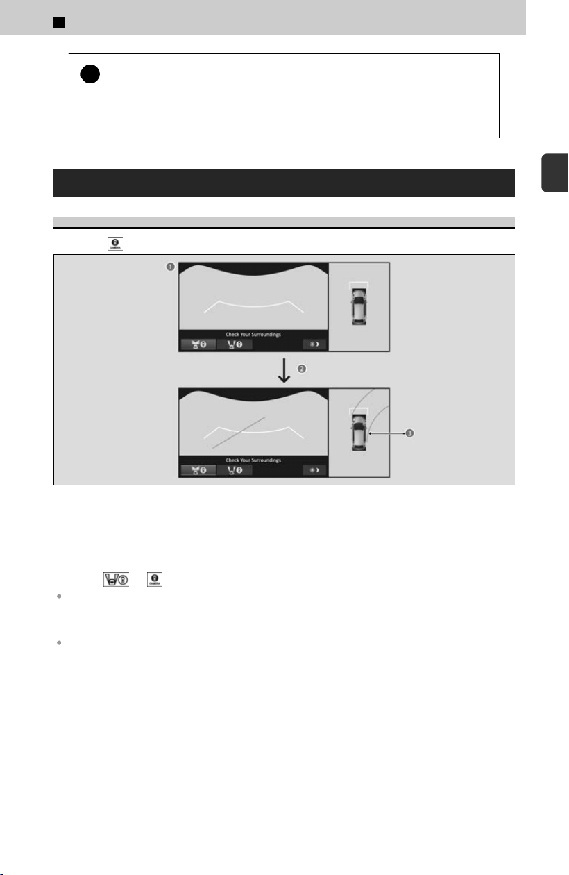
!
The guidelines should be used as a reference only.
The positions
/distances indicated by the guidelines and camera views on the
display may differ from the actual positions/distances due to the changes in the
vehicle height, road conditions, and other factors.
Using the Multi View Camera System
Checking the Front of Your Vehicle
Press the
button to display the front view screen.
a Front View + Ground View
b When the steering wheel is turned more than 90 degrees.
c The dynamic guideline appears approx. 14 inches (35 cm) outside the vehicle
body.
Pressing
or button switches to the side view screen.
If the vehicle speed exceeds 16 mph (25 km/h) while the front or side view image from the
multi view camera is displayed, the screen automatically switches to the audio/information
screen.
The ground view can be displayed even with the door mirrors folded. However, the viewable
angle and blind spot change.
2
Driving Operation > Multi View Camera System
*
135
2
Driving Operation
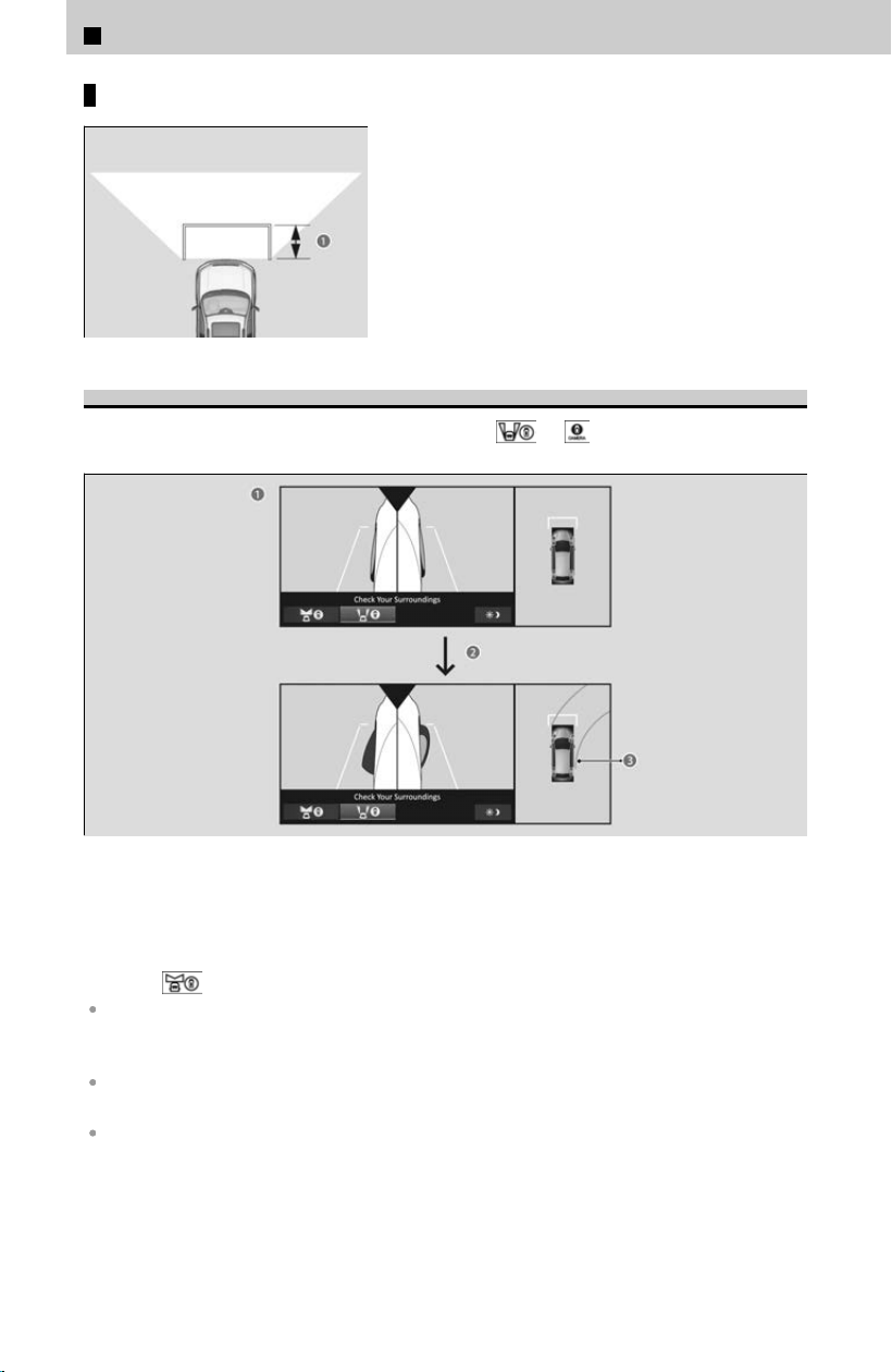
Distance between the vehicle and guideline
The distance (a) from the vehicle to the
guideline is approx. 43 inches (1.1 m).
Checking the Sides of Your Vehicle
While displaying the front view screen, press the
or button to display the
side view screen.
a Side View + Ground View
b When the steering wheel is turned more than 90 degrees.
c The dynamic guideline appears approx. 14 inches (35 cm) outside the vehicle
body.
Pressing
switches to the front view screen.
If the vehicle speed exceeds 16 mph (25 km/h) while the front or side view image from the
multi view camera is displayed, the screen automatically switches to the audio/information
screen.
The ground view can be displayed even with the door mirrors folded. However, the viewable
angle and blind spot change.
When the door mirrors are folded, the side views cannot be displayed.
2
Driving Operation > Multi View Camera System
*
136
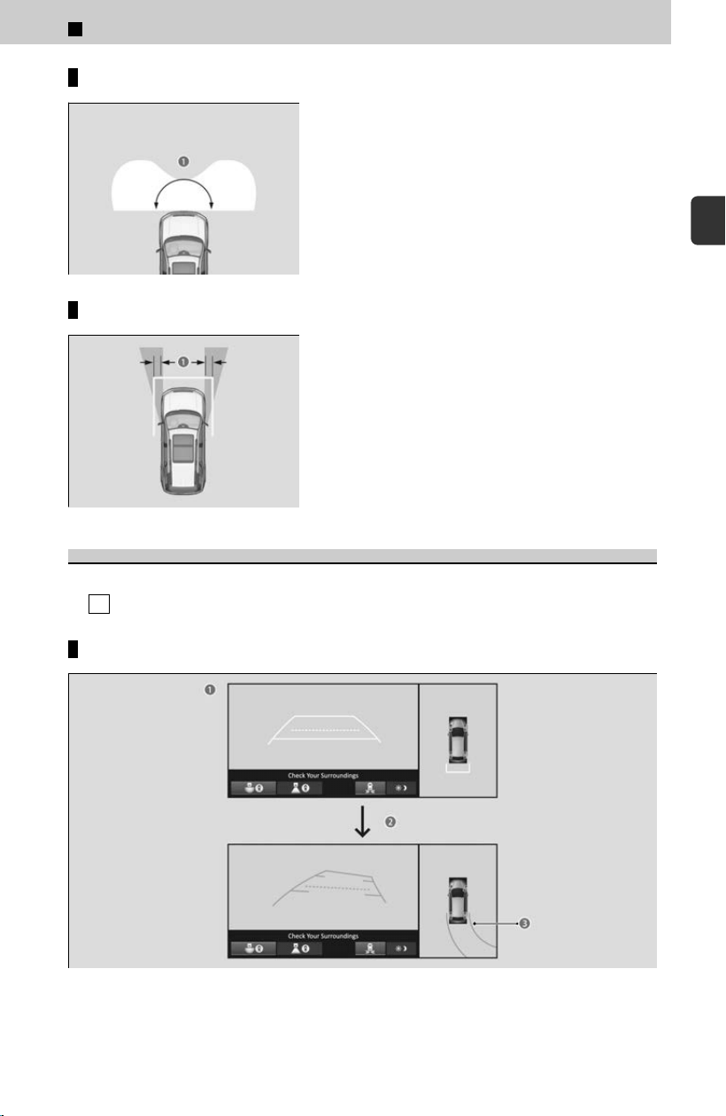
Camera display area
The angle provided by the front view screen (a)
is 180 degrees. The front view screen is useful
when you need to check for vehicles crossing
from either direction at an intersection with poor
visibility.
≫
The front view is a wide-angled view. The image will
be largely distorted, and objects may appear closer or
more distant than they actually are.
Distance between the vehicle and guideline
Images of the front side of the vehicle captured
by side cameras are displayed on the display.
Approximate distance (a) the projection lines
indicate is 16 inches (40 cm) from the vehicle.
Checking for Obstacles at the Back of Your Vehicle
The display automatically changes to the rear view when the shift position is changed
t
o R .
Rear wide view + ground view
a Rear Wide View + Ground View
b When the steering wheel is turned more than 90 degrees.
2
Driving Operation > Multi View Camera System
*
137
2
Driving Operation
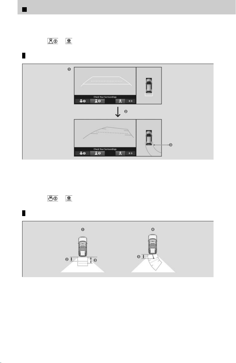
c The dynamic guideline appears approx. 14 inches (35 cm) outside the vehicle
body.
Pressing
or button switches to the rear view screen.
Rear view + ground view
a Rear View + Ground View
b When the steering wheel is turned more than 90 degrees.
c The dynamic guideline appears approx. 14 inches (35 cm) outside the vehicle
body.
Pressing
or button switches to the rear wide view screen.
Distance between the vehicle and guideline
a Approximate distances the guidelines indicate
b Approx. 23 inches (60 cm)
c Approx. 35 inches (90 cm)
d Approximate distances the projection lines indicate
e Approx. 23 inches (60 cm)
2
Driving Operation > Multi View Camera System
*
138
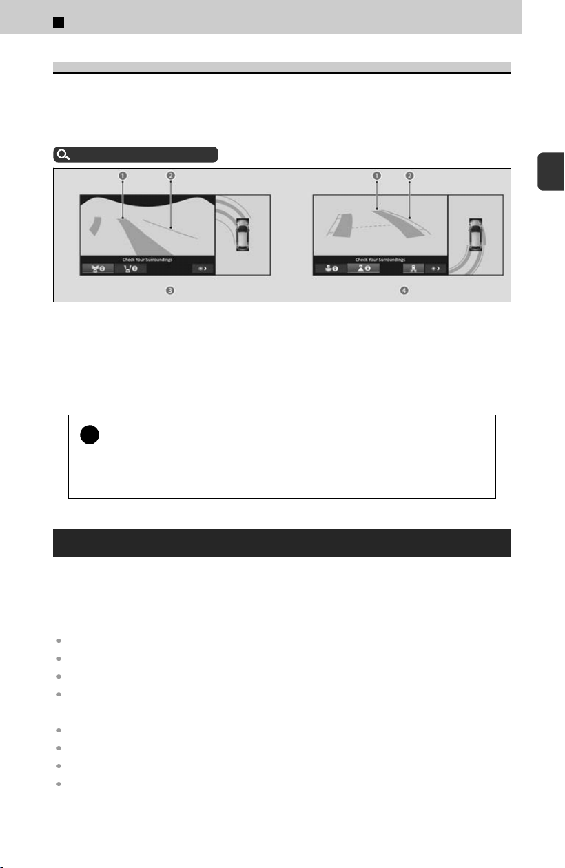
TrailWatch™
When the drive mode is in TRAIL mode
, images with tire direction lines from the
multi view camera system are displayed while your vehicle speed is about 12 mph
(20 km/h) or lower. When the vehicle’s speed reaches about 16 mph (25 km/h) or
higher, the display will return to the previous screen.
Drive Mode System
u
P.159
a Tire Direction Lines
b The dynamic guideline appears approx. 14 inches (35 cm) outside the vehicle
body.
c Front View + Ground View
d Rear View/Rear Wide View + Ground View
!
The tire direction lines should be used as a reference only.
The positions
/distances indicated by the tire direction lines and camera views
on the display may differ from the actual positions/distances due to the
changes in the vehicle height, road conditions, and other factors.
Multi View Camera System Limitations
Clean camera lenses with the frontview or rearview camera washer or a soft cloth
mois
turized with water, mild detergent, or glass cleaner.
The camera may become blurry under the following conditions. In these cases, we
recommend checking visually without using the multi view camera system.
You activate the system in bad weather (heavy rain, snow, fog, etc.) or in the dark.
Camera temperatures are high.
A sudden change between light and dark, such as an entrance or exit of a tunnel.
You drive into the sunlight (e.g., at dawn or dusk.)
Have your vehicle checked by a dealer in the following situations:
When the Dynamic Guideline becomes inaccurate
A camera lens is scratched.
A camera or the area around the camera has been severely impacted.
An error message is displayed while the multi view camera system is in use.
2
Driving Operation > Multi View Camera System
*
139
2
Driving Operation

The camera image is not displayed on the screen while driving at speeds below 12 mph (20
km/h).
2
Driving Operation > Multi View Camera System
*
140

2
Driving Operation >
Refueling
Fuel Information
Fuel Recommendation
Unleaded gasoline, pump octane number 87 or higher
Use of a lower octane gasoline can cause a persistent, heavy metallic knocking noise
that can lead t
o engine damage.
≫
Use of gasoline with these additives may adversely affect performance, and cause the
malfunction indicator lamp on your instrument panel to come on. If this happens, contact a
dealer for service. Some gasoline today is blended with oxygenates such as ethanol. Your
vehicle is designed to operate on oxygenated gasoline containing up to 15% ethanol by
volume. Do not use gasoline containing methanol. If you notice any undesirable operating
symptoms, try another service station or switch to another brand of gasoline.
Top Tier Detergent Gasoline
Because the level of detergency and additives in gasoline vary in the market, Honda
endorses the use o
f “TOP TIER Detergent Gasoline” where available to help maintain
the performance and reliability of your vehicle. TOP TIER Detergent Gasoline meets a
new gasoline standard jointly established by leading automotive manufacturers to
meet the needs of today’s advanced engines.
Qualifying gasoline retailers will, in most cases, identify their gasoline as having met
“TOP TIER Detergent Gasoline” standards at the retail location. This fuel is
guaranteed to contain the proper level of detergent additives and be free of metallic
additives. The proper level of detergent additives, and absence of harmful metallic
additives in gasoline, help avoid buildup of deposits in your engine and emission
control system.
For further important fuel-related information for your vehicle, or on information on
gasoline that does not contain MMT, visit www.hondacars.com. In Canada, visit
www.honda.ca(English), www.honda.ca/fr(French) for additional information on
gasoline. For more information on top tier gasoline, visit www.toptiergas.com.
!
We recommend quality gasoline containing detergent additives that
help pr
event fuel system and engine deposits. In addition, in order to
maintain good performance, fuel economy, and emissions control, we
strongly recommend the use of gasoline that does NOT contain
harmful manganese-based fuel additives such as MMT, if such
gasoline is available.
141
2
Driving Operation
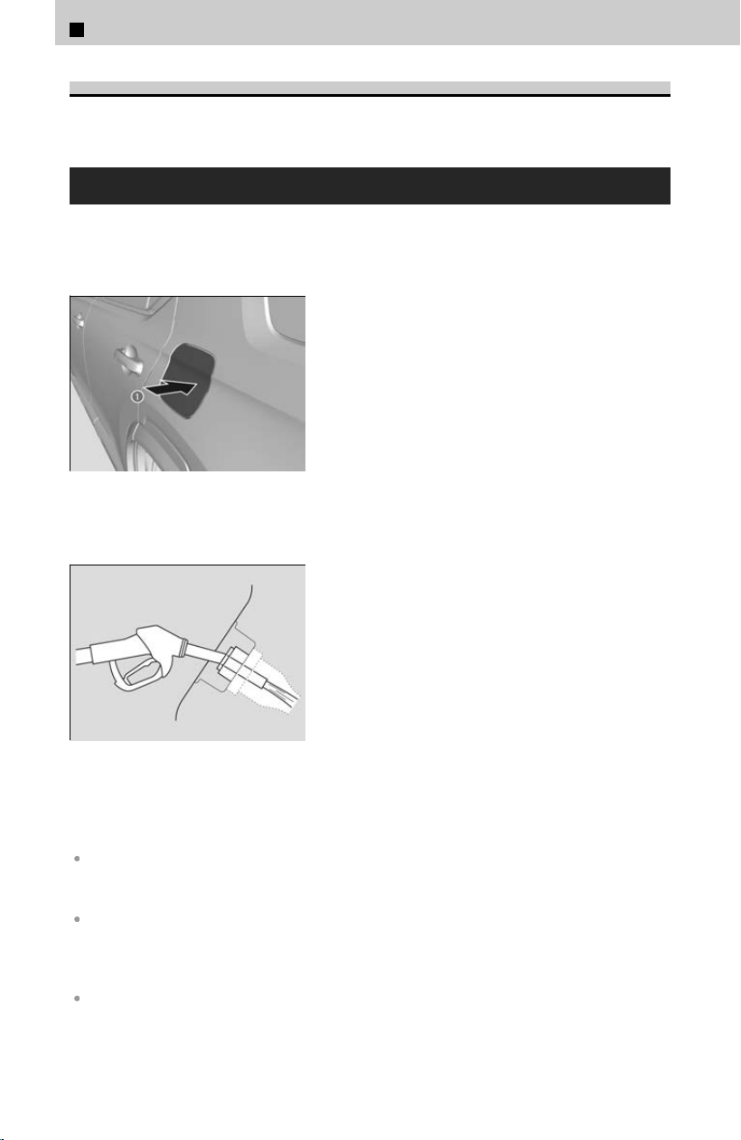
Fuel Tank Capacity
18.5 US gal (70 L)
How to Refuel
Your fuel tank is not equipped with a fuel fil
ler cap. You can insert the filler nozzle
directly into the filler neck. The tank seals itself again when you pull out the filler
nozzle.
[1] Stop your vehicle with the service station
pump on the left side of the vehicle in the
rear.
[2] Turn off the engine and then unlock the
driver’s door.
≫
The fuel fill door on the outer side of the vehicle
will unlock.
[3] Press and release the area indicated by the
arr
ow (a). You will hear a click and the lid
will open slightly.
[4] Manually pull the fuel fill door to a fully open
position.
[5] Place the end of the filler nozzle on the lower
part of filler opening, then insert it slowly
and fully.
≫
Make sure that the end of the filler nozzle goes
down along with the filler pipe.
≫
Keep the filler nozzle level.
≫
When the tank is full, the filler nozzle will click
off automatically.
≫
If you do not fill up the tank to full, always add a
minimum of 2.6 US gal (10.0 L) of fuel.
≫
After filling, wait about five seconds before
removing the filler nozzle.
[6] Shut the fuel fil
l door by hand.
The fuel filler opening is designed to accept only service station filler nozzles for refueling. Use
of smaller diameter tubes (e.g., those used to siphon fuel for other uses) or other non-service
station devices can damage the area in and around the filler opening.
The filler nozzle automatically stops to leave space in the fuel tank so that fuel does not
overflow as a result of changes in air temperature. Do not continue to add fuel after the filler
nozzle has automatically stopped. Additional fuel can exceed the full tank capacity and cause
fuel to spill.
If you repeatedly fill the tank with less than the specified minimum amount of fuel, the
malfunction indicator lamp may come on. If this happens, have your vehicle checked by a
dealer.
2
Driving Operation > Refueling
142

Use the lock tab or the master door lock switch to unlock the fuel fill door. The vehicle doors
and fuel fill door automatically relock if the keyless remote unlock function is used. This can
be deactivated by briefly opening then closing the driver’s door.
Using the Walk away auto lock® feature will also lock the fuel fill door. Always make sure both
the driver’s door and fuel fill door are unlocked before attempting to open the fuel fill door.
Locking the Doors and Tailgate (Walk Away Auto Lock®)
u
P.55
If the fuel filler nozzle keeps turning off when the tank is not full, there may be a problem with
the pump’s fuel vapor recovery system. Try filling at another pump. If this does not fix the
problem, consult a dealer.
If you have to refuel your vehicle from a portable container, use the funnel provided with your
vehicle.
Refueling From a Portable Fuel Container
u
P.412
3 WARNING
Gasoline is highly flammable and explosive.
Y
ou can be burned or seriously injured when handling fuel.
Stop the engine, and keep heat, sparks, and flames away.
Handle fuel only outdoors.
Wipe up spills immediately.
2
Driving Operation > Refueling
143
2
Driving Operation

2
Driving Operation >
Fuel Economy and CO2 Emissions
Improving Fuel Economy and Reducing CO2
Emissions
Achieving fuel economy and reducing CO
2
emis
sions is dependent on several factors,
including driving conditions, load weight, idling time, driving habits, and vehicle
condition. Depending on these and other factors, you may not achieve the rated fuel
economy of this vehicle.
Direct calculation is the recommended method to determine actual fuel consumed
while driving
.
Miles driven ÷ Gallons of fuel = Miles per Gallon
100 x Liters of fuel ÷ Kilometers driven = L per 100 km
In Canada, posted fuel economy numbers are established following a simulated test.
For more information on how this test is performed, please visit https://
www.nrcan.gc.ca and search for “fuel consumption testing” in the search field at the
top of the page.
Maintenance and Fuel Economy
You can optimize your fuel economy with proper maintenance of your vehicle. Always
maintain y
our vehicle in accordance with the messages displayed on the driver
information interface.
Use engine oil with the viscosity recommended.
Recommended Engine Oil
u
P.354
Maintain the specified tire pressure.
Do not load the vehicle with excess cargo.
Keep your vehicle clean. A buildup of snow or mud on your vehicle’s underside adds weight
and increases wind resistance.
144
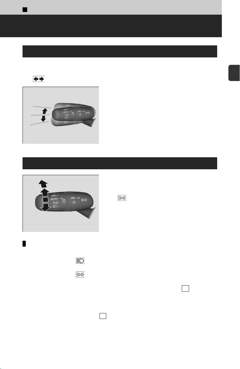
2
Driving Operation >
Turn Signals/Light Switches
Turn Signals
Push the lever up or down based on the direction you want to turn, and the turn signal
wil
l blink.
The turn signal indicator will blink when the external turn signal blinks.
When you lightly push the lever up or down and
release it, the turn signal will blink 3 times.
≫
If you lightly push the lever in the opposite direction
while it is blinking, the blinking will stop.
Headlights/Parking Lights
The lights will turn on automatically depending on
the ambient brightness.
They can also be switched on and off manually.
≫
The lights on indicator in the instrument panel
will turn on.
The exterior lights will switch on automatically
when the light s
witch is set to AUTO while the
power mode is in ON.
Manual operation
Headlights/parking lights:
Turn the light switch to
.
Parking lights:
Turn the light switch to .
Headlight/parking lights off:
Turn the light switch to OFF and release it while the transmission is in P and the
parking brake is applied.
The lights will come back on automatically when:
≫
The light switch is turned to OFF again and released.
≫
The transmission is changed out of P and the parking brake is released.
When the parking lights are on, the side marker, tail, and rear license plate lights will
also s
witch on.
145
2
Driving Operation
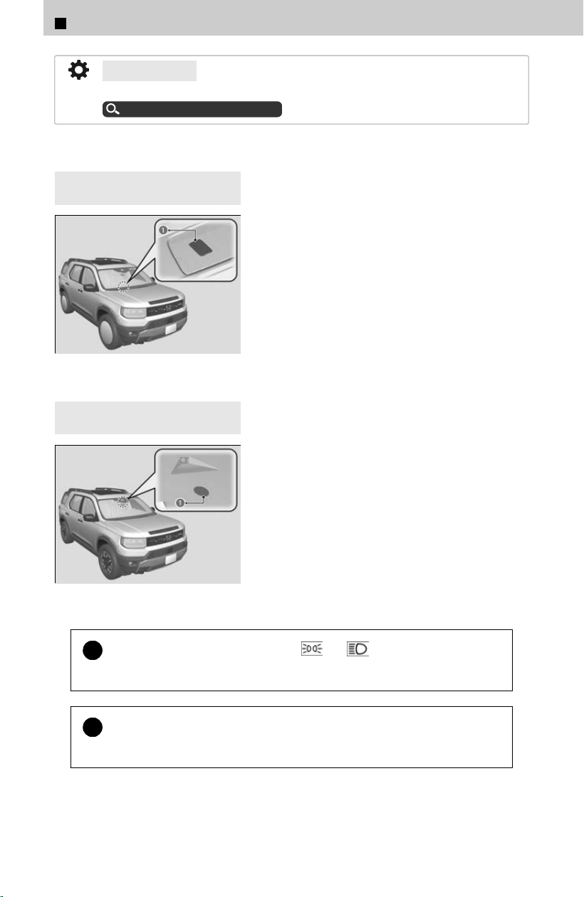
4
U.S. models
You can change the auto light sensitivity setting.
Customized Features
u
P.239
The light sensor is in the location shown below.
Do not cover the light sensor.
4
Models without automatic
intermittent wipers
a Light Sensor
4
Models with automatic
intermittent wipers
a Light Sensor
!
When the light switch is turned to
or and the power is
turned to OFF, a beeper sounds when the driver’s door is opened.
!
If you suspect that the headlights are not positioned properly, have the
v
ehicle inspected by a dealer.
2
Driving Operation > Turn Signals/Light Switches
146
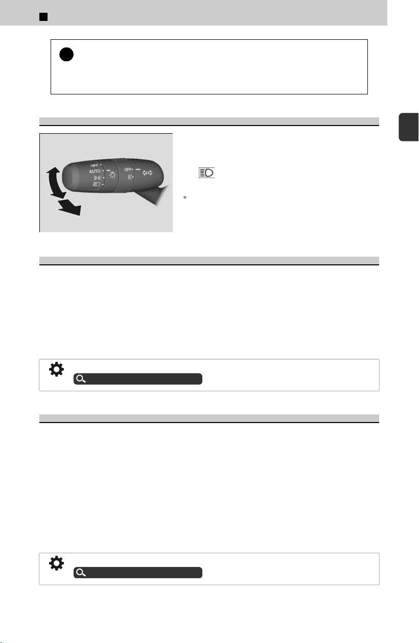
!
When the light switch is turned to A
UTO and the ambient light levels
are low, the headlights and parking lights will switch on if you unlock a
door. They will switch off when the door is locked.
High Beams
When the headlights are on, push the lever
forward.
Pull the lever back to return to low beams.
The high beam indicator in the instrument
panel will turn on when the high beams are on.
Flashing the high beams: Pull the lever back, and
release it.
Headlight Integration with Wipers
The headlights automatically come on when the wipers are used several times within
a c
ertain number of intervals with the headlight switch in AUTO.
The headlights automatically go off a few minutes later if the wipers are stopped.
This feature activates while the headlights are off in AUTO.
The instrument panel brightness does not change when the headlights come on.
At dark ambient light levels, the automatic lighting control feature turns on the
headlights, regardless of the number of wiper sweeps.
You can turn the headlight integration with wipers function on and off.
Customized Features
u
P.239
Automatic Lighting Off Feature
The headlights, all other exterior lights, and the instrument panel lights turn off 15
sec
onds after you set the power mode to VEHICLE OFF, take the remote with you, and
close the driver’s door.
If you set the power mode to VEHICLE OFF with the headlight switch on, but do not
open the door, the lights turn off after 10 minutes (3 minutes, if the switch is in the
AUTO position).
The lights turn on again when you unlock or open the driver’s door.
If you unlock the door, but do not open it within 15 seconds, the lights go off.
If you open the driver’s door, you will hear a reminder chime alerting you that the
lights are on.
You can change the headlight auto off timer setting.
Customized Features
u
P.239
2
Driving Operation > Turn Signals/Light Switches
147
2
Driving Operation
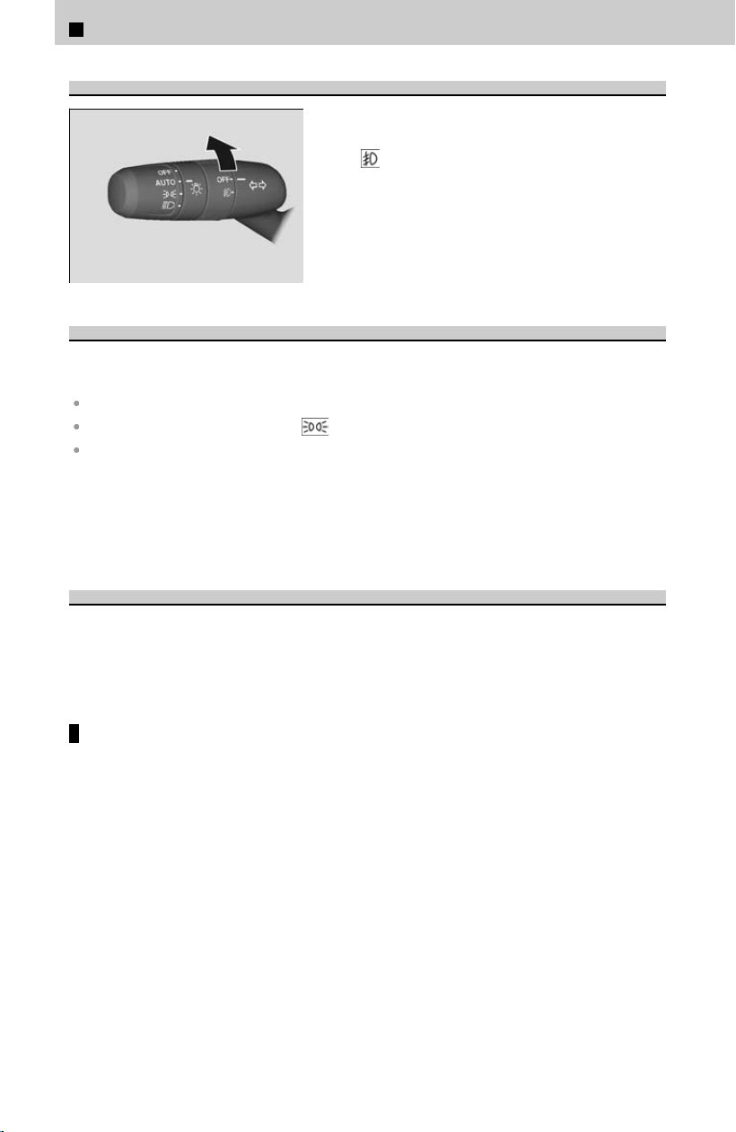
Fog Lights
*
When the low beam headlights are on, turn the
fog light switch on to use the fog lights.
≫
The fog light indicator in the instrument panel will
turn on.
Daytime Running Lights
The parking/daytime running lights come on when the following conditions have been
met:
The power mode is in ON.
The headlight switch is in AUTO or .
The parking brake is released.
The lights remain on even if you set the parking brake.
Setting the power mode to VEHICLE OFF will turn off the daytime running lights.
The daytime running lights are off once the headlight switch is turned on, or when the
headlight s
witch is in AUTO and it is getting darker outside.
Auto High-Beam
The front sensor camera detects the light sources ahead of the vehicle such as the
lights o
f a preceding or oncoming vehicle, or street lights. When you are driving at
night, the system automatically switches the headlights between low beam and high
beam depending on the situation.
How to use the auto high-beam
Activating the system
When all of the following conditions have been met, the auto high-beam indicator
c
omes on and automatically switches between the high beam and low beam,
depending on the situation.
*: Not available on all models
2
Driving Operation > Turn Signals/Light Switches
148
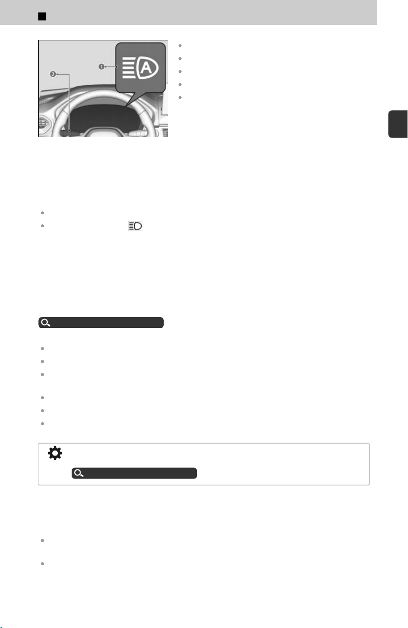
a Auto High-Beam Indicator
b Light Switch
The power mode is in ON.
The light switch is in AUTO.
The lever is in the low beam position.
The headlights have been automatically activated.
It is dark outside the vehicle.
If the auto high-beam indicator does not come on even when all the conditions have
been met
, carry out either of the procedures below and the indicator will come on.
Pull the lever toward you and release it.
Turn the light switch to then turn the light switch to AUTO.
The auto high-beam system does not always operate in every situation. This system is
jus
t for assisting the driver. Always observe your surroundings and manually switch
the headlights between high beam and low beam if necessary.
The range and the distance at which the camera can recognize light sources varies
depending on conditions surrounding your vehicle.
Regarding the handling of the camera mounted to the inside of the windshield, refer
t
o the following.
Front Sensor Camera
u
P.270
For the auto high-beam to work properly:
Do not place an object that reflects light on the dashboard.
Keep the windshield around the camera clean.
When cleaning the windshield, be careful not to apply the windshield cleanser to the camera
lens.
Do not attach an object, sticker, or film to the area around the camera.
Do not touch the camera lens.
If the camera receives a strong impact, or repairing of the area near the camera is required,
consult a dealer.
How to turn off the Auto High-Beam System: You can turn the auto high-beam
system on and off.
Customized Features
u
P.239
If you find the timing of beam changes inconvenient for driving, change the headlight
beams manually.
If the Some driver assist systems cannot operate: Camera temperature too high
message appears:
Use the climate control system to cool down the interior and, if necessary, also use defroster
mode with the airflow directed toward the camera.
Start driving the vehicle to lower the windshield temperature, which cools down the area
around the camera.
2
Driving Operation > Turn Signals/Light Switches
149
2
Driving Operation

If the Some driver assist systems cannot operate: Clean front windshield or poor
viewing condition. message appears:
Park your vehicle in a safe place, and make sure the windshield is clean. Clean the windshield
if it is dirty. If the message does not disappear after driven for a while, have your vehicle
checked by a dealer.
In the following cases, the auto high-beam system may not switch the headlights
pr
operly or the switching timing may be changed.
If the automatic switching operation does not fit your driving habits, please switch the
headlights manually.
The brightness of the lights from the preceding or oncoming vehicle is intense or poor.
Visibility is poor due to the weather (rain, snow, fog, windshield frost, etc.).
Surrounding light sources like street lights, electric billboards, and traffic lights are
illuminating the road ahead.
The brightness level of the road ahead constantly changes.
The road is bumpy or has many curves.
A vehicle suddenly appears in front of you, or a vehicle in front of you is not in the preceding or
oncoming direction.
Your vehicle is tilted with a heavy load in the rear.
A traffic sign, mirror, or other reflective object ahead is reflecting strong light toward the
vehicle.
The oncoming vehicle frequently disappears under roadside trees or behind median barriers.
The preceding or oncoming vehicle is a motorcycle, bicycle, mobility scooter, or other small
vehicle.
The auto high-beam system keeps the headlight low beam on when:
Windshield wipers are operating at a high speed.
The camera has detected a dense fog.
Automatic switching between high-beam and low-beam
When the auto high-beam indicator comes on, the headlights switch between high
beam and lo
w beam based on the following conditions.
High beam
All of the following conditions must be met before the high beams turn on.
Your vehicle speed is 23 mph (37 km/h) or more.
There are no preceding or oncoming vehicles with headlights or taillights turned on.
There are few street lights on the road ahead.
Low beam
One of the following conditions must be met before the low beams turn on.
Your vehicle speed is 15 mph (24 km/h) or less.
There is a preceding or oncoming vehicle with headlights or taillights turned on.
There are many street lights on the road ahead.
2
Driving Operation > Turn Signals/Light Switches
150

Manual switching between high-beam and low-beam
If you want to manually switch the headlights between high beam and low beam,
f
ollow either of the procedures below. Note that when you do this, the auto high-
beam indicator will turn off and the auto high-beam will be deactivated.
Using the lever:
Pull the lever toward you for flashing the high beams then release it.
≫
To reactivate the auto high-beam, follow either of the procedures below and the auto high-
beam indicator will come on.
Pull the lever toward you and release it.
Turn the light switch to and then to AUTO when the lever is in the low beam position.
Using the light switch:
Turn the light switch to
.
≫
To reactivate the auto high-beam, turn the light switch to AUTO when the lever is in the low
beam position and the auto high-beam indicator will come on.
2
Driving Operation > Turn Signals/Light Switches
151
2
Driving Operation
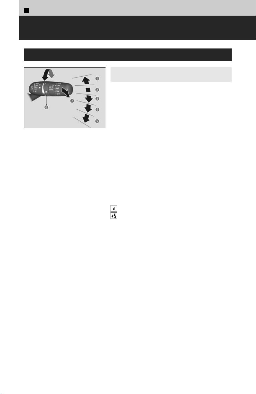
2
Driving Operation >
Wipers and Washers
Windshield Wiper/Washer
4
Models with manual intermittent
operation
a MIS
T
The wipers run at high speed until you release
the lever.
b OFF
c INT
Low speed with intermittent
d LO
Low speed wipe
e HI
High speed wipe
f Intermittent Time Adjustment Ring
Turn the adjustment ring to adjust the
wiper operation.
: Lower speed, fewer sweeps
: Higher speed, more sweeps
g Pull to use washer
Sprays while you pull the lever toward you.
When you release the lever for more than one
second, the spray stops, the wipers sweep two or
three more times to clear the windshield, and
then stop.
152
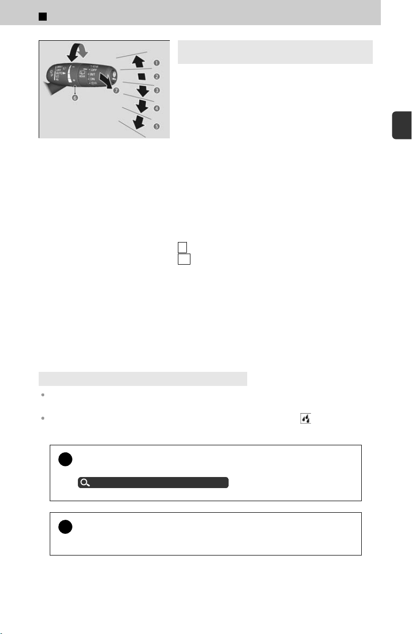
4
Models with automatic intermittent
operation
a MIS
T
The wipers run at high speed until you release the
lever.
b OFF
c AUTO
d LO
Low speed wipe
e HI
High speed wipe
f AUTO sensitivity adjustment
You can adjust the sensitivity of the rainfall
sensor.
−
: Low sensitivity
+ : High sensitivity
g Pull to use washer
Sprays on the windshield and front view camera
while you pull the lever toward you.
When you release the lever for more than one
second, the spray stops, the wipers sweep two or
three more times to clear the windshield, and
then stop.
4
Models with intermittent time adjustment ring
If the vehicle speeds up while the wipers are operating intermittently, the length of the wipe
interval shortens.
When the vehicle speeds up, the wiper operation’s shortest delay setting and the LO
setting become the same.
!
When lifting the front wiper arms, move them into the maintenance
position bef
ore lifting them.
Lifting the Front Wiper Arms
u
P.363
!
Do not use the wipers when the windshield is dry. The windshield will
g
et scratched, or the rubber blades will get damaged.
2
Driving Operation > Wipers and Washers
153
2
Driving Operation
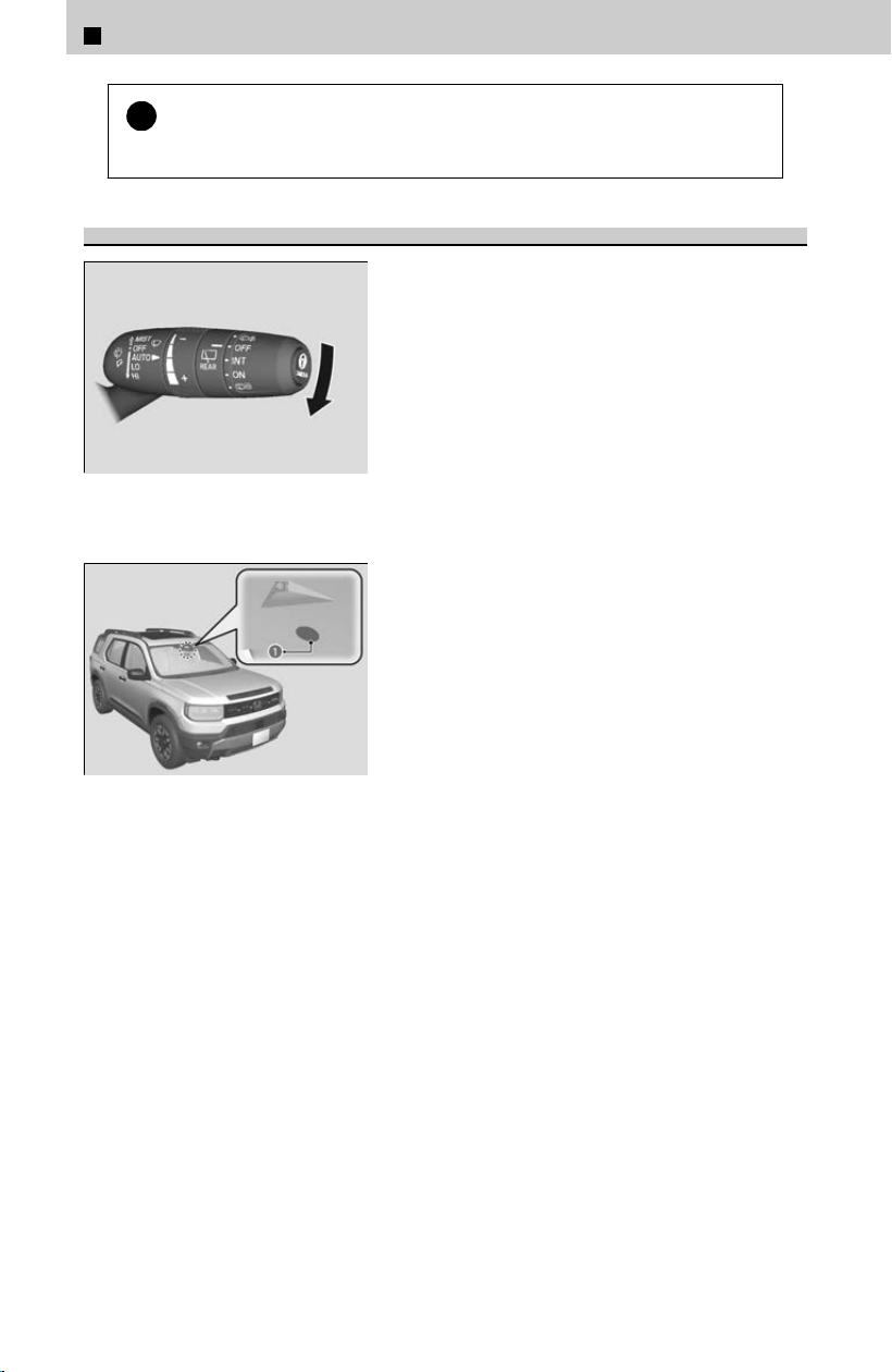
!
Turn the washers off if no washer fluid comes out. The pump may get
damag
ed.
Automatic Intermittent Wipers
*
When you push the lever down to AUTO,
the windshield wipers sweep once, and go
into the automatic mode.
The wipers operate intermittently, at lowspeed,
or at high speed and stop in accordance with the
amount of rainfall the rainfall sensor detects.
≫
If the sensor reacts to something other than rain and
the wipers operate unnecessarily, you can stop them
by moving the lever to the OFF position.
a Rainfall Sensor
The rainfall sensor is located at the top of the
middle o
f the front windshield.
AUTO should al
ways be turned OFF before the following situations in order to prevent
severe damage to the wiper system:
• Cleaning the windshield
• Driving through a car wash
• No rain present
*: Not available on all models
2
Driving Operation > Wipers and Washers
154

Rear Wiper/Washer
a OFF
b INT (Intermittent)
c ON (Continuous wipe)
d Washer
Sprays on the rear window and rear view camera
*
while you rotate the switch to this position.
Hold it to activate the rear wiper and to spray the
washer.
Once released, the washer spray will stop and the
rear wiper will return to its selected switch setting
after a few sweeps.
When you change the transmission to R with the windshield wiper activated, the rear wiper
operates automatically even if its switch is off.
What to Do If
When the wipers are not moving
The wiper motor may stop temporarily to prevent an overload.
Wiper operation will return to normal within a few minutes.
When the wiper blades are stuck to the windshield glass due to
freezing in cold weather
In cold weather, the blades may freeze to the windshield.
Operating the wipers in this condition may damage the wipers. Use the defogger or
heat
ed windshield
*
to warm the windshield, then turn the wipers on.
When snow has accumulated on the wipers
If the wipers stop operating due to an obstacle such as the buildup of snow, park
the v
ehicle in a safe place.
Rotate the wiper switch to OFF, set the power mode to ACCESSORY or VEHICLE
OFF, then remove the obstacle.
*: Not available on all models
2
Driving Operation > Wipers and Washers
155
2
Driving Operation
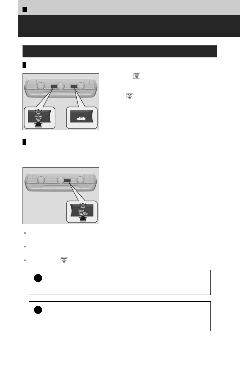
2
Driving Operation >
Defroster
Defrosting the Windshield and Windows
When defogging the front or side windows
Pressing the button turns the air conditioning
system on and automatically switches the system
to fresh air mode.
Press the button again to turn off, the system
returns to the previous settings.
Rear defogger/heated door mirror button
Press the rear defogger and heated door mirror button to defog the rear window and
mirr
ors when the power mode is in ON.
The rear defogger and heated door mirror automatically switch off after 10-30 minutes,
depending on the outside temperature.
When the power mode is set to ON and the outside temperature is below 41°F (5°C), the
heated door mirror may automatically activate for 10 minutes.
If you press the button during Auto Idle Stop, the engine restarts automatically.
!
For your safety, make sure you have a clear view through all the
windo
ws before driving.
!
After defrosting the windows, switch over to fresh air mode.
If y
ou keep the system in recirculation mode, the windows may fog up from
humidity. This impedes visibility.
156
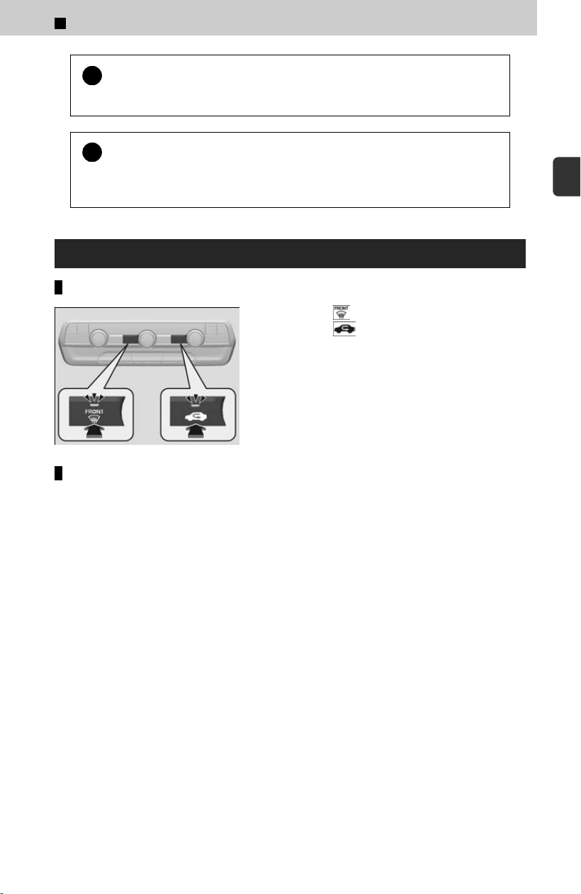
!
Do not set the temperature near the upper or lower limit. When cold
air hits the windshield, the outside o
f the windshield may fog up.
!
This system consumes a lot of power, so turn it off when the window
has been def
ogged. This may weaken the 12-volt battery, making it
difficult to start the engine.
What to Do If
To rapidly defrost the windows
[1] Press the button.
[2] Press the button (indicator on).
When the side window gets fogged up
Adjust the nearest climate control vent so that it blows directly on the side window.
2
Driving Operation > Defroster
157
2
Driving Operation
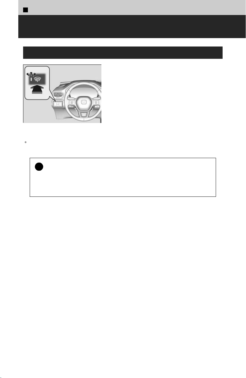
2
Driving Operation >
Heated Windshield Button
*
Heated Windshield Button
Press the heated windshield button to deice the
windshield at the wiper park area of the
windshield when the power mode is in ON.
The heated windshield will automatically switch off after 15 minutes.
When the outside temperature is below 39°F (4°C), the heated windshield may automatically
activate for up to 15 minutes.
!
This system consumes a lot of power, so turn it off when the window
has been deic
ed. Also, do not use the system for a long period when
the engine is idling. This may weaken the 12-volt battery, making it
difficult to start the engine.
*: Not available on all models
158
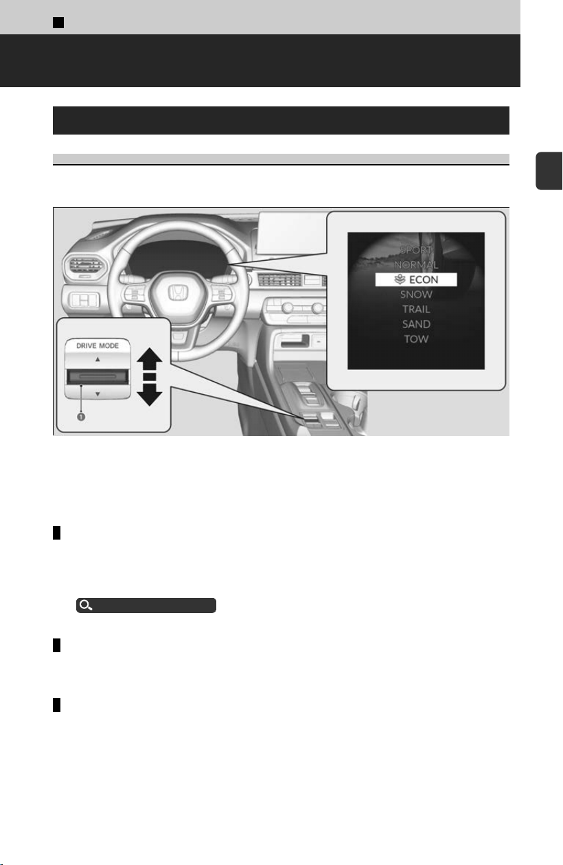
2
Driving Operation >
Driving Features
Drive Mode System
Selecting the Drive Mode
Press the drive mode switch (a) t
o select the appropriate mode. The mode you
select appears on the driver information interface.
The mode may not be able to be changed under some driving conditions. If there is a
vehicle system failure, a message will also appear on the driver information interface,
and you cannot change the mode.
SPORT mode
Enhances responsiveness to the driver’s input.
≫
While in SPORT mode, the Auto Idle Stop System will stay disabled regardless of the Auto
Idle Stop OFF button.
Auto Idle Stop
u
P.161
NORMAL mode
Optimizes the balance between operability and comfort.
ECON mode
Facilitates fuel
-efficient driving.
≫
While in ECON mode, the climate control system will be less effective and the vehicle
slower to accelerate.
159
2
Driving Operation

SNOW mode
Maximizes controllability on snowy roads through powertrain settings.
≫
While in SNOW mode, the Auto Idle Stop System will stay disabled regardless of the Auto
Idle Stop OFF button.
Auto Idle Stop
u
P.161
!
SNOW mode does not al
low you to drive on snowy or frozen roads in
all situations. There are limits to SNOW mode.
When driving on snowy or frozen roads, mount winter tires or tire chains
*
,
reduce speed, and maintain sufficient distance between vehicles.
Winter Tires
u
P.373
TRAIL mode
Maximizes controllability on roads with mud, gravel, or loose dirt.
≫
TrailWatch™: While in TRAIL Mode, images from the Multi View Camera System are
displayed while your vehicle speed is about 12 mph (20 km/h) or lower. When the vehicle’s
speed reaches about 16 mph (25 km/h) or higher, the display will return to the previous
screen.
About Multi View Camera System
u
P.132
≫
While in TRAIL mode, the Auto Idle Stop System will stay disabled regardless of the Auto
Idle Stop OFF button.
Auto Idle Stop
u
P.161
≫
While in TRAIL mode, the VSA® OFF indicator turns on to indicate that the VSA® system is
optimized for this drive mode.
VSA® On and Off
u
P.167
≫
When the Drive Mode is in TRAIL mode, Low Speed Braking Control does not operate.
About Low Speed Braking Control
u
P.280
SAND mode
Maximizes controllability on soft, sandy roads or off-highway terrain through
po
wertrain settings.
≫
While in SAND mode, the Auto Idle Stop System will stay disabled regardless of the Auto
Idle Stop OFF button.
Auto Idle Stop
u
P.161
≫
While in SAND mode, the VSA® OFF indicator turns on to indicate that the VSA® system is
optimized for this drive mode.
VSA® On and Off
u
P.167
TOW mode
Optimizes balance between driving performance and comfort when towing a trailer.
*: Not available on all models
2
Driving Operation > Driving Features
160
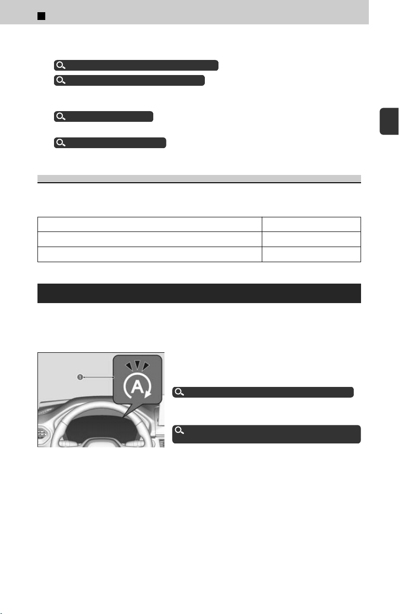
≫
When the Drive Mode is in TOW mode, Low Speed Braking Control and the parking sensor
system do not operate when reversing.
About Low Speed Braking Control
u
P.280
About Parking Sensor System
u
P.318
≫
While in TOW mode, the Auto Idle Stop System will stay disabled regardless of the Auto
Idle Stop OFF button.
Auto Idle Stop
u
P.161
≫
For more details on towing, refer to the following.
Towing Preparation
u
P.95
Next Start-Up Mode
The mode for the next start-up is saved according to the following chart. Each keyless
r
emote has its own mode saved.
Last Mode Next Mode
Any mode other than EC
ON NORMAL
ECON ECON
Auto Idle Stop
To help maximize fuel economy, the engine automatically stops when the vehicle
c
omes to a stop, depending on environmental and vehicle operating conditions. The
indicator (green) comes on at this time.
a Auto Idle Stop Indicator
(Green)
The environmental and vehicle conditions that
impact Aut
o Idle Stop system operation are
varied.
Auto Idle Stop System Activates When
u
P.162
The engine then restarts once the vehicle is about
t
o move again, and the indicator (green) goes off.
The Engine Automatically Restarts When
u
P.163
If the driver’s door is opened while the indicator
(
green) comes on, a buzzer sounds to notify you
that the Auto Idle Stop function is in operation.
A message associated with Auto Idle Stop
appears on the driver information interface.
2
Driving Operation > Driving Features
161
2
Driving Operation
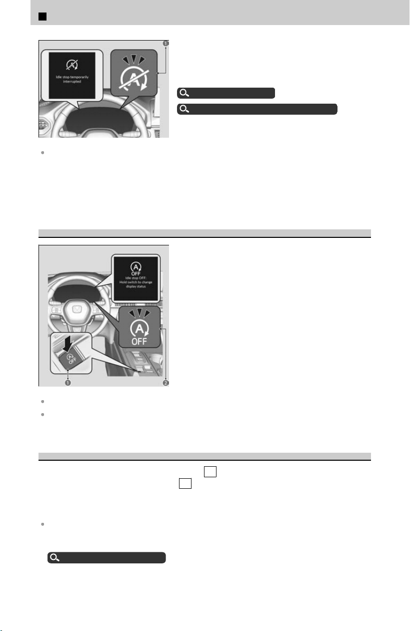
The Auto Idle Stop suspend indicator (a) comes
on and a message appears on the driver
information interface when the Auto Idle Stop
system cannot be activated.
Indicator List
u
P.323
Auto Idle Stop System ON/OFF
u
P.162
The 12-volt battery installed in this vehicle is specifically designed for a model with Auto Idle
Stop.
Using a 12-volt battery other than this specified t
ype may shorten the 12-volt battery
life, and prevent Auto Idle Stop from activating. If you need to replace the 12-volt
battery, make sure to select the specified type. Ask a dealer for more details.
Auto Idle Stop System ON/OFF
To turn the Auto Idle Stop system off, press Auto
Idle Stop OFF button (a). The Auto Idle Stop
system stops.
≫
Auto Idle Stop system will stop, the Auto Idle Stop
OFF indicator (b) will come on, and a message will
appear on the driver information interface.
The Auto Idle Stop system is turned on every time
y
ou start the engine, even if you turned it off the
last time you drove the vehicle.
If you turn off the Auto Idle Stop system while it is activated, the engine will restart.
If you press and hold the Auto Idle Stop OFF button, you can select whether or not to display
the status messages.
Auto Idle Stop Activates When:
The vehicle stops with the transmission in D
and the brake pedal depressed.
When you put the transmission into P , the Auto Idle Stop continues to operate,
even if the brake pedal is released.
≫
If you depress the brake pedal, the engine may automatically restart.
Do not open the hood while the Auto Idle Stop function is activated. If the hood is opened, the
engine will not restart automatically.
In this case, restart the engine with the ENGINE START/STOP button.
Starting the Engine
u
P.111
2
Driving Operation > Driving Features
162

Pressing the ENGINE START/STOP button causes the engine to no longer restart
automatically. Follow the standard procedure to start the engine.
Starting the Engine
u
P.111
When ACC with Low Speed Follow is in operation, the vehicle stops without depressing the
brake pedal and Auto Idle Stop may activate. In such cases, the engine may restart if you
change the shift position other than D .
Auto idle stop does not activate when:
The Auto Idle Stop OFF button is pressed.
The driver’s seat belt is not fastened.
The engine is not adequately warmed up or coolant temperature is high.
The transmission fluid temperature is low or high.
The vehicle comes to a stop again before the vehicle speed reaches 3 mph (5 km/h) after
the engine starts.
The vehicle is stopped on a steep incline.
The transmission is in a position other than D .
The engine is started with the hood open.
≫
Turn off the engine. Close the hood before you restart the engine to activate Auto Idle
Stop.
The 12-volt battery charge is low.
The internal temperature of the 12-volt battery is 14°F (−10°C ) or less.
The climate control system is in use, and the outside temperature is below −4°F (−20°C) or
over 104°F (40°C).
The climate control system is in use, and the temperature is set to Hi or Lo.
is on (indicator on).
The Drive Mode is changed to SNOW, TOW, SPORT, TRAIL, or SAND mode.
Auto idle stop may not activate when:
The vehicle is stopped by braking suddenly.
The steering wheel is operated.
The fan speed is high.
The climate control system is in use, and there is a significant difference between the set
temperature and the actual interior temperature.
The climate control system is in use, and humidity in the interior is high.
The Engine Automatically Restarts When:
The brake pedal is released (without the automatic brake hold system activated).
The accelerator pedal is depressed (with the automatic brake hold system activated).
Automatic Brake Hold
u
P.123
If you are using an electronic device during Auto Idle Stop, the device may temporarily be
turned off when the engine restarts.
The engine restarts even if the brake pedal is depressed
*1
when:
2
Driving Operation > Driving Features
163
2
Driving Operation

The Auto Idle Stop OFF button is pressed.
The steering wheel is operated.
The transmission is put into R or S , or when it is set from N to D .
≫
If you put the transmission into P after the Auto Idle Stop activates, the Auto Idle Stop
continues to operate. In this case, the engine restarts when you depress the brake pedal.
The pressure on the brake pedal is reduced and the vehicle starts moving while stopped on an
incline.
The brake pedal is released slightly during a stop.
The 12-volt battery charge becomes low.
The accelerator pedal is depressed.
The driver’s seat belt is unlatched.
is ON (indicator on).
The climate control system is in use, and the difference between the set temperature and
actual interior temperature becomes significant.
The climate control system is being used to dehumidify the interior.
The Drive Mode is changed to SNOW, TOW, SPORT, TRAIL, or SAND mode.
The vehicle ahead of you starts again when your vehicle stops automatically with ACC with
Low Speed Follow.
*1: With the automatic brake hold system activated, you can release the brake pedal while Auto
I
dle Stop is in operation.
If the automatic brake hold system has been turned off, or if there is a problem with the
system, the engine will restart automatically when you release the brake pedal.
Automatic Brake Hold
u
P.123
Starting Assist Brake Function
Briefly keeps the brake applied after releasing the brake pedal to restart the engine.
This can keep your vehicle from unexpectedly moving while on an incline.
Hill Descent Control System
When driving down hills where engine braking is not enough to decelerate the vehicle,
this s
ystem helps maintain a constant vehicle speed without needing to depress the
brake pedal.
2
Driving Operation > Driving Features
164
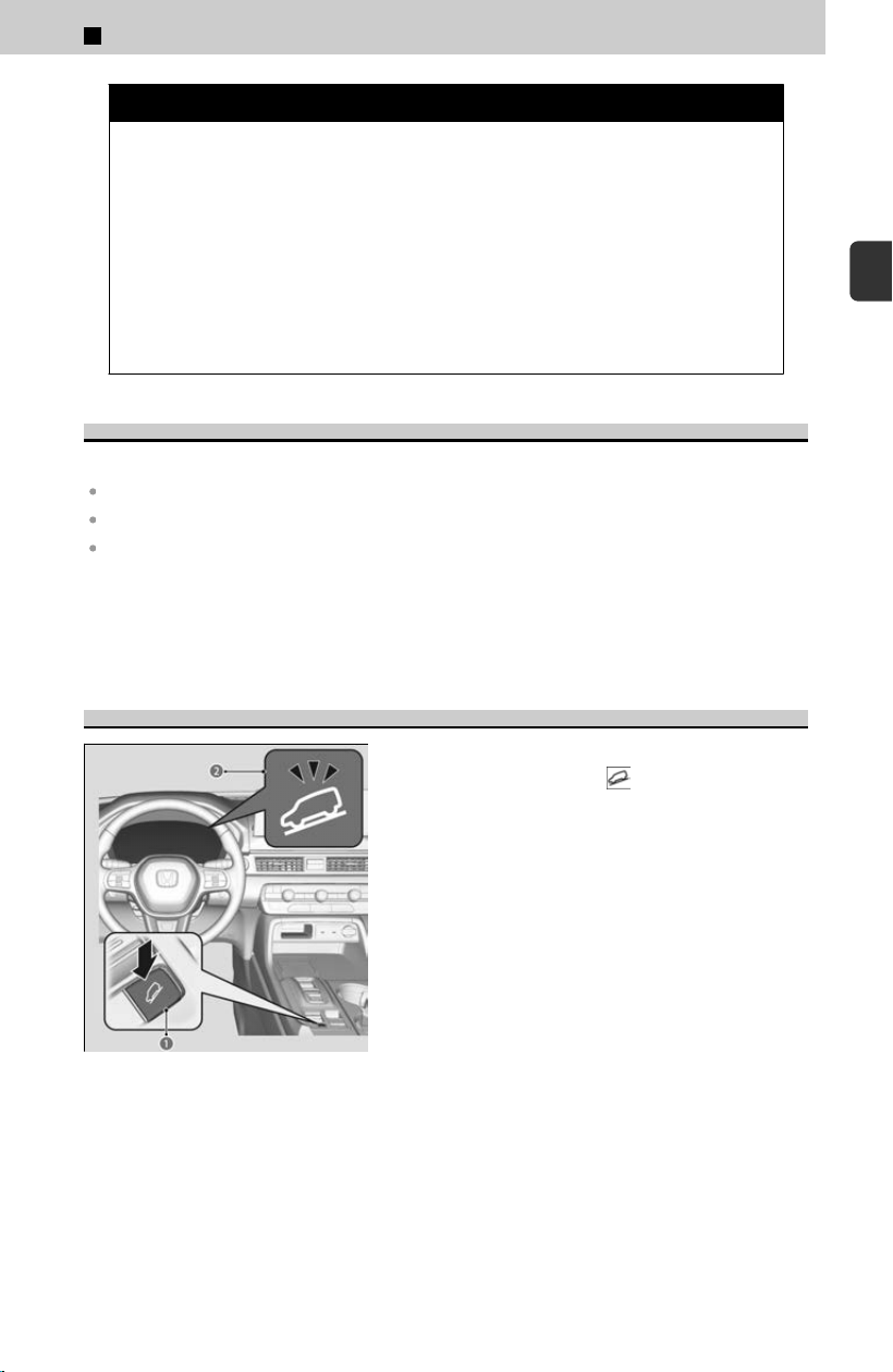
3 WARNING
Hill descent control cannot maintain a constant vehicle speed in every
situation.
When driving do
wn a very steep hill or on slippery road surfaces, the vehicle
may not be able to maintain the vehicle speed and could cause a crash,
resulting in serious injury or death.
Since Hill Descent Control is not designed to increase the limits of vehicle
performance, the driver must always be aware of road surface conditions
and drive safely.
Operating Conditions
The system operates under the following conditions.
Driving at a speed between about 2-12 mph (3-20 km/h).
Driving downhill.
Accelerator pedal and brake pedal are not depressed.
≫
The brake lights automatically come on while the system is in operation.
≫
The system may not operate when driving down a gentle slope.
≫
The system may activate even when not driving downhill, such as when the vehicle leans
while driving over uneven surfaces.
How to Activate the System
When the vehicle speed is less than about 12
mph (20 km/h), press the button (a) to turn
the system on.
≫
The system goes into standby mode, and the Hill
Descent Control System indicator (white) (b) comes
on.
The system starts operating when the Hill
Desc
ent Control System indicator (green) comes
on.
2
Driving Operation > Driving Features
165
2
Driving Operation
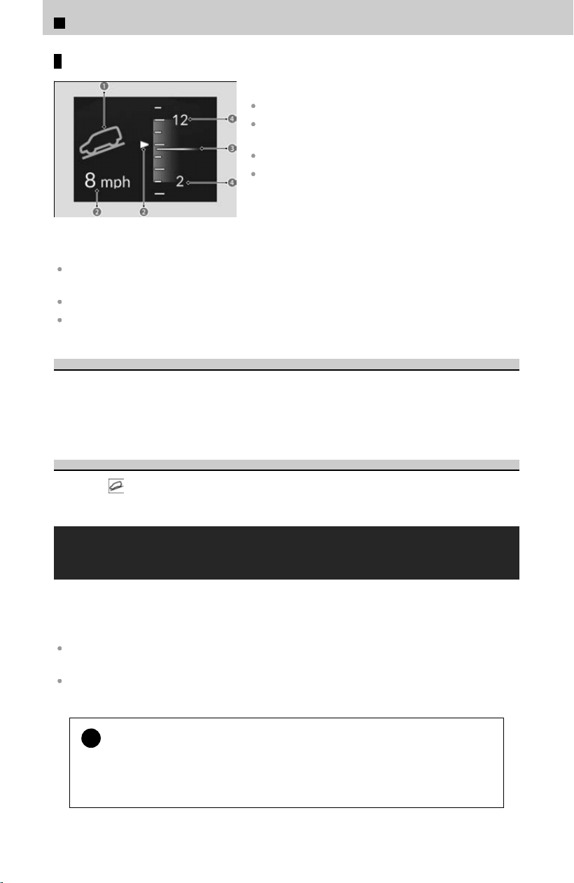
Driver Information Interface Display
a The system’s operating status
Green: Activated
White: Standby
b V
ehicle speed display
White: Set speed
Gray: Current speed
≫
Blinks when the vehicle speed is above the
operating speed.
c Curr
ent speed
d Operating range of set speed
Using the system repeatedly for a long time may cause the brakes to heat up and make the
system go into standby mode temporarily.
The pedals may vibrate or you may hear the system working when in operation.
The brake lights automatically come on while the system is in operation.
To Adjust the Set Speed
Depress the accelerator pedal or brake pedal to adjust the vehicle speed within the
oper
ating range. The vehicle speed at which you release the accelerator pedal or
brake pedal will be the set speed.
To Cancel
Press the
button to turn off the system.
Vehicle Stability Assist™ (VSA®), aka Electronic
Stability Control (ESC), System
VSA® helps stabilize the vehicle during cornering if the vehicle turns more or less than
what w
as intended. It also assists in maintaining traction on slippery surfaces.
It does so by regulating engine output and selectively applying the brakes.
The main function of the VSA® system is generally known as Electronic Stability Control (ESC).
The system also includes a traction control function.
In certain unusual conditions when your vehicle gets stuck in shallow mud or fresh snow, it
may be easier to free it with the VSA® temporarily switched off.
!
VSA® cannot enhance stability in all driving situations and does not
c
ontrol the entire braking system. You still need to drive and corner at
speeds appropriate for the conditions and always leave a sufficient
margin of safety.
2
Driving Operation > Driving Features
166
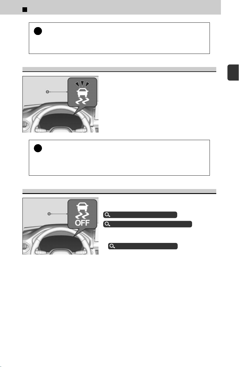
!
The VSA® may not function properly if tire type and size are mixed.
Mak
e sure to use the same size and type of tire, and the air pressures
as specified.
VSA® Operation
When VSA® activates, the VSA® system indicator
(a) will also blink.
≫
The engine and motor do not respond to the
accelerator.
≫
You may also notice some noise from the hydraulic
brake system.
!
When the VSA® system indicator comes on and stays on while driving,
ther
e may be a problem with the system.
While this may not interfere with normal driving, have your vehicle checked by a
dealer immediately.
VSA® On and Off
a VSA® OFF Indicator
You can partially disable VSA® features using the
driv
er information interface.
Switching the Display
u
P.334
Vehicle Stability Assist Mode
u
P.340
≫
VSA® ON/OFF does not function while the drive mode
is in SAND mode or TRAIL mode.
Drive Mode System
u
P.159
Your vehicle will have normal braking and cornering ability, but traction control
function wil
l be less effective.
≫
Traction control function change not required during SAND mode and TRAIL mode.
VSA® is turned on every time you start the engine, even if you turned it off the last
time y
ou drove the vehicle.
2
Driving Operation > Driving Features
167
2
Driving Operation
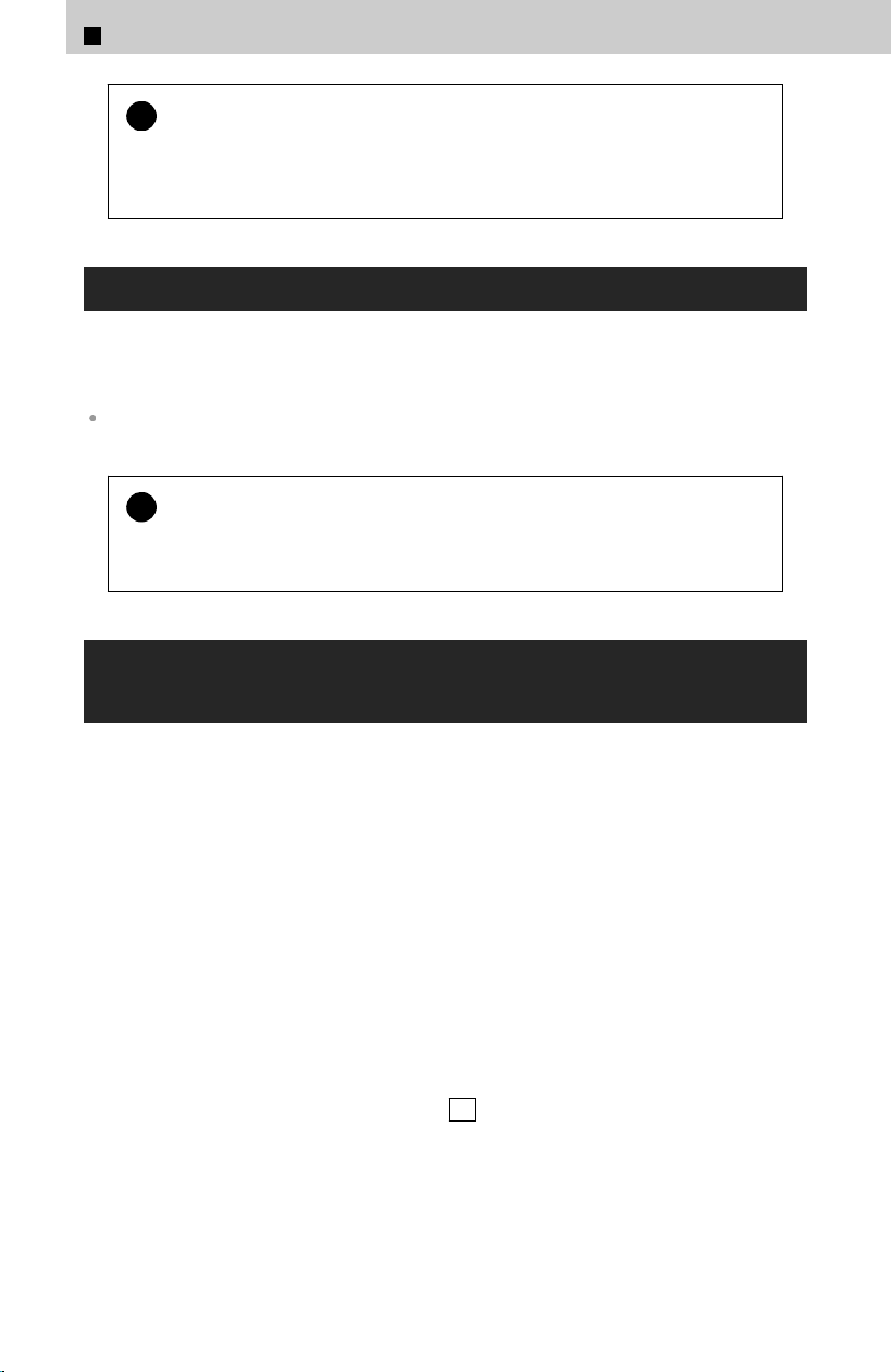
!
You should only attempt to free your vehicle with the VSA® off if you
ar
e not able to free it when the VSA® is on.
Immediately after freeing your vehicle, be sure to switch VSA® on again. We do
not recommend driving your vehicle with the VSA® system switched off.
Agile Handling Assist
Lightly brakes each of the front and rear wheels, as needed, when you turn the
s
teering wheel, and helps support the vehicle’s stability and performance during
cornering.
When the VSA® system indicator comes on and stays on while driving, the agile handling
assist does not activate.
!
The agile handling assist cannot enhance stability in all driving
situations
. You still need to drive and corner at speeds appropriate for
the conditions and always leave a sufficient margin of safety.
Intelligent Variable Torque Management (i-
VTM4™) AWD System
The intelligent variable torque management (i-VTM4™) AWD system is a full time all
wheel driv
e system that automatically controls and transfers varying amount of
engine torque to all wheels independently according to the driving conditions.
You still need to exercise the same care when accelerating, steering, and brakingthat
you would in a two-wheel drive vehicle.
Avoid continuously driving on slippery surfaces where a wheel is likely to spin out,
and do not drive if the AWD temperature too hot. Do not drive. Idle engine to
allow system to cool. message appears. Driving continuously under such conditions
can damage the system’s torque distribution unit.
If theAWD temperature too hot. Do not drive. Idle engine to allow system to
cool. message appears on the driver information interface while driving, it indicates
the differential temperature is too high. If this happens, pull to the side of the road
when it is safe, change the shift position to P , and idle the engine until the message
disappears. If the message does not disappear, take your vehicle to a dealer to have it
checked.
2
Driving Operation > Driving Features
168
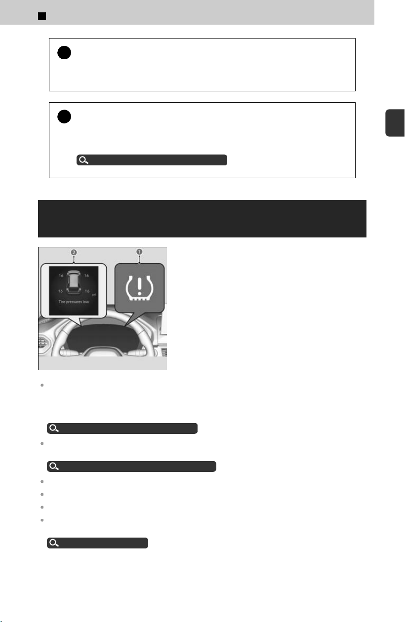
!
Do not continuously spin the front tires of your vehicle. Continuously
spinning the fr
ont tires can cause transmission or rear differential
damage.
!
The intelligent variable torque management (i-VTM4™) AWD system
may not function pr
operly if tire type and size are mixed.
Make sure to use the same size and type of tire, and the air pressures as
specified.
Tire and Wheel Replacement
u
P.373
Tire Pressure Monitoring System (TPMS) with
Tire Fill Assist
Monitors the tire pressure while you are driving. If
your vehicle’s tire pressure becomes significantly
low, the Low Tire Pressure/TPMS indicator (a)
comes on and the Tire pressures low message
(b) appears.
Only use genuine wheels equipped with TPMS since your vehicle’s wheels are equipped with
the low tire pressure/TPMS sensor.
If you drive your vehicle without the genuine wheels equipped with TPMS, the low tire
pressure/TPMS indicator blinks for one minute and then stays on.
Tire and Wheel Replacement
u
P.373
Conditions such as low ambient temperature and altitude change directly affect tire pressure
and can trigger the Low Tire Pressure/TPMS indicator to come on.
Low Tire Pressure/TPMS Indicator
u
P.328
Tires can become under-inflated in colder weather.
Tires can become overinflated in warmer weather.
The Low Tire Pressure/TPMS indicator will not come on as a result of overinflation.
The TPMS can audibly and visually inform you of changes in tire pressure of the individual tire
that you are adjusting.
Tire Fill Assist
u
P.368
2
Driving Operation > Driving Features
169
2
Driving Operation
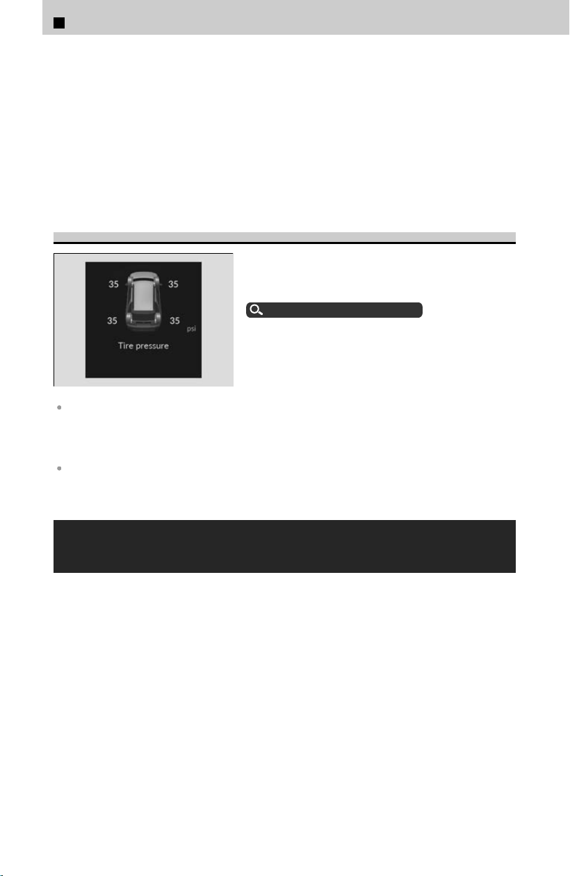
Tire pressure monitor system problem. message may appear if you drive with a tire
not equipped with a TPMS sensor (including the compact spare tire), or if there is a
problem with the TPMS.
The pressure displayed on the driver information interface can be slightly different
from the actual pressure as measured by a gauge. If there is a significant difference
between the two values, or if the Low Tire Pressure/TPMS indicator and the message
on the driver information interface do not go off after you have inflated the tire to the
specified pressure, have the system checked by a dealer.
Tire Pressure Monitor
To select the tire pressure monitor, set the power
mode to ON, and roll the right selector wheel until
you see the tire pressure screen.
Switching the Display
u
P.334
≫
The pressure for each tire is displayed in psi.
The system checks each tire’s position on the vehicle each time the power mode is set to ON.
“--” is displayed when the vehicle has not yet identified the location each sensor or when
there is a problem. To allow the vehicle to identify the sensor locations, drive at a speed of
more than 25 mph (40 km/h) until each tire pressure is displayed.
If the pressure display does not update even after driving for one minute or if “--” is displayed
for each wheel with an amber tire icon, have your vehicle checked by a dealer.
Tire Pressure Monitoring System (TPMS) -
Required Federal Explanation
Each tire, including the spare (if provided), should be checked
monthl
y when cold and inflated to the inflation pressure
recommended by the vehicle manufacturer on the vehicle
placard or tire inflation pressure label.
(If your vehicle has tires of a different size than the size
indicated on the vehicle placard or tire inflation pressure label,
you should determine the proper tire inflation pressure for those
tires.)
2
Driving Operation > Driving Features
170

As an added safety feature, your vehicle has been equipped
with a tire pressure monitoring system (TPMS) that illuminates a
low tire pressure telltale when one or more of your tires is
significantly under-inflated.
Accordingly, when the low tire pressure telltale illuminates, you
should s
top and check your tires as soon as possible, and inflate
them to the proper pressure.
Driving on a significantl
y under-inflated tire causes the tire to
overheat and can lead to tire failure. Under-inflation also
reduces fuel efficiency and tire tread life, and may affect the
vehicle’s handling and stopping ability.
Please note that the TPMS is not a substitute for proper tire
maintenance, and it is the driver’s responsibility to maintain
correct tire pressure, even if under-inflation has not reached the
level to trigger illumination of the TPMS low tire pressure
telltale.
Your vehicle has also been equipped with a TPMS malfunction
indicat
or to indicate when the system is not operating properly.
The TPMS malfunction indicator is combined with the low tire
pressure telltale.
When the system detects a malfunction, the telltale will flash for
approximately one minute and then remain continuously
illuminated.
This sequence will continue upon subsequent vehicle start-ups
as long as the malfunction e
xists.
When the malfunction indicator is illuminated, the system may
not be able to detect or signal low tire pressure as intended.
2
Driving Operation > Driving Features
171
2
Driving Operation

TPMS malfunctions may occur for a variety of reasons, including
the installation of replacement or alternate tires or wheels on
the vehicle that prevent the TPMS from functioning properly.
Always check the TPMS malfunction telltale after replacing one
or mor
e tires or wheels on your vehicle to ensure that the
replacement or alternate tires and wheels allow the TPMS to
continue to function properly.
2
Driving Operation > Driving Features
172

Interior Lights
Interior Light Switches・・・・・・・・・・・・・・・・・・・・・・・・ 174
Map Light Switches・・・・・・・・・・・・・・・・・・・・・・・・・・・・ 174
Cargo Area Light・・・・・・・・・・・・・・・・・・・・・・・・・・・・・・・ 175
Interior Convenience Items
Glove Box・・・・・・・・・・・・・・・・・・・・・・・・・・・・・・・・・・・・・・176
Center Console Box・・・・・・・・・・・・・・・・・・・・・・・・・・・・176
Accessory Power Sockets・・・・・・・・・・・・・・・・・・・・・ 176
AC Power Outlet
*
・・・・・・・・・・・・・・・・・・・・・・・・・・・・・・ 177
Wireless Charger・・・・・・・・・・・・・・・・・・・・・・・・・・・・・・ 179
Coat Hooks・・・・・・・・・・・・・・・・・・・・・・・・・・・・・・・・・・・・ 181
Cargo Hooks・・・・・・・・・・・・・・・・・・・・・・・・・・・・・・・・・・・ 181
Tie-Down Anchors・・・・・・・・・・・・・・・・・・・・・・・・・・・・・ 182
Sunglasses Holder・・・・・・・・・・・・・・・・・・・・・・・・・・・・・182
Under-Floor Storage Area・・・・・・・・・・・・・・・・・・・・・ 182
Rear Door Sunshades
*
・・・・・・・・・・・・・・・・・・・・・・・・・ 183
Beverage Holders・・・・・・・・・・・・・・・・・・・・・・・・・・・・・・183
HomeLink® Universal Transceiver
*1
・・・・・・・・・・・・ 184
Seat Heaters/Ventilators
Using the Front Seat Heaters/Ventilators
*
・・・・・ 188
Using the Rear Seat Heaters
*
・・・・・・・・・・・・・・・・・・ 189
Heated Steering Wheel
*
Using the Heated Steering Wheel・・・・・・・・・・・・・・190
Panoramic Roof
*
Opening/Closing the Panoramic Roof・・・・・・・・・・191
What to Do If・・・・・・・・・・・・・・・・・・・・・・・・・・・・・・・・・・ 193
Climate Control System
Automatic Climate Control System・・・・・・・・・・・・ 194
Using Automatic Climate Control・・・・・・・・・・・・・・ 195
Rear Climate Control System・・・・・・・・・・・・・・・・・・ 197
In-Vehicle Infotainment
About Your In-Vehicle Infotainment・・・・・・・・・・・ 199
Audio System Basic Operation・・・・・・・・・・・・・・・・ 199
USB Ports・・・・・・・・・・・・・・・・・・・・・・・・・・・・・・・・・・・・・・202
Audio Remote Controls・・・・・・・・・・・・・・・・・・・・・・・・ 203
Connecting a Device・・・・・・・・・・・・・・・・・・・・・・・・・・・ 204
About System Updates・・・・・・・・・・・・・・・・・・・・・・・・ 206
12.3″ Color Touchscreen
Star
t Up・・・・・・・・・・・・・・・・・・・・・・・・・・・・・・・・・・・・・・・ 208
Reboot Audio・・・・・・・・・・・・・・・・・・・・・・・・・・・・・・・・・・ 209
Home Screen・・・・・・・・・・・・・・・・・・・・・・・・・・・・・・・・・・ 209
System Updates・・・・・・・・・・・・・・・・・・・・・・・・・・・・・・・ 210
Trip Computer・・・・・・・・・・・・・・・・・・・・・・・・・・・・・・・・・ 212
Adjusting the Clock・・・・・・・・・・・・・・・・・・・・・・・・・・・・ 212
Adjusting the Sound・・・・・・・・・・・・・・・・・・・・・・・・・・・ 213
Changing the Screen Brightness・・・・・・・・・・・・・・・ 214
Alexa Built-In・・・・・・・・・・・・・・・・・・・・・・・・・・・・・・・・・・ 214
Playing AM/FM Radio・・・・・・・・・・・・・・・・・・・・・・・・・・ 215
About Audio Playback・・・・・・・・・・・・・・・・・・・・・・・・・ 217
HondaLink®・・・・・・・・・・・・・・・・・・・・・・・・・・・・・・・・・・・・ 221
HondaLink® Service・・・・・・・・・・・・・・・・・・・・・・・・・・・・222
Wi-Fi Connection・・・・・・・・・・・・・・・・・・・・・・・・・・・・・・ 222
AT&T Hotspot・・・・・・・・・・・・・・・・・・・・・・・・・・・・・・・・・・ 224
Apple CarPlay・・・・・・・・・・・・・・・・・・・・・・・・・・・・・・・・・ 225
Android Auto™・・・・・・・・・・・・・・・・・・・・・・・・・・・・・・・・・ 228
Google built-in・・・・・・・・・・・・・・・・・・・・・・・・・・・・・・・・・230
User Information・・・・・・・・・・・・・・・・・・・・・・・・・・・・・・ 232
Bluetooth® HandsFreeLink®・・・・・・・・・・・・・・・・・・・・234
Customized Features・・・・・・・・・・・・・・・・・・・・・・・・・・ 239
General Information on the Audio
System
Compatible iPod, iPhone, and USB Flash Drives・・・
・・・・・・・・・・・・・・・・・・・・・・・・・・・・・・・・・・・・・・・・・・・・・・・ 249
Honda App License Agreement・・・・・・・・・・・・・・・・ 250
About Open Source Licenses・・・・・・・・・・・・・・・・・・ 260
License Information・・・・・・・・・・・・・・・・・・・・・・・・・・・ 260
Legal Information on Apple CarPlay/Android Auto
・・・・・・・・・・・・・・・・・・・・・・・・・・・・・・・・・・・・・・・・・・・・・・・ 263
*: Not available on all models
Controls
173
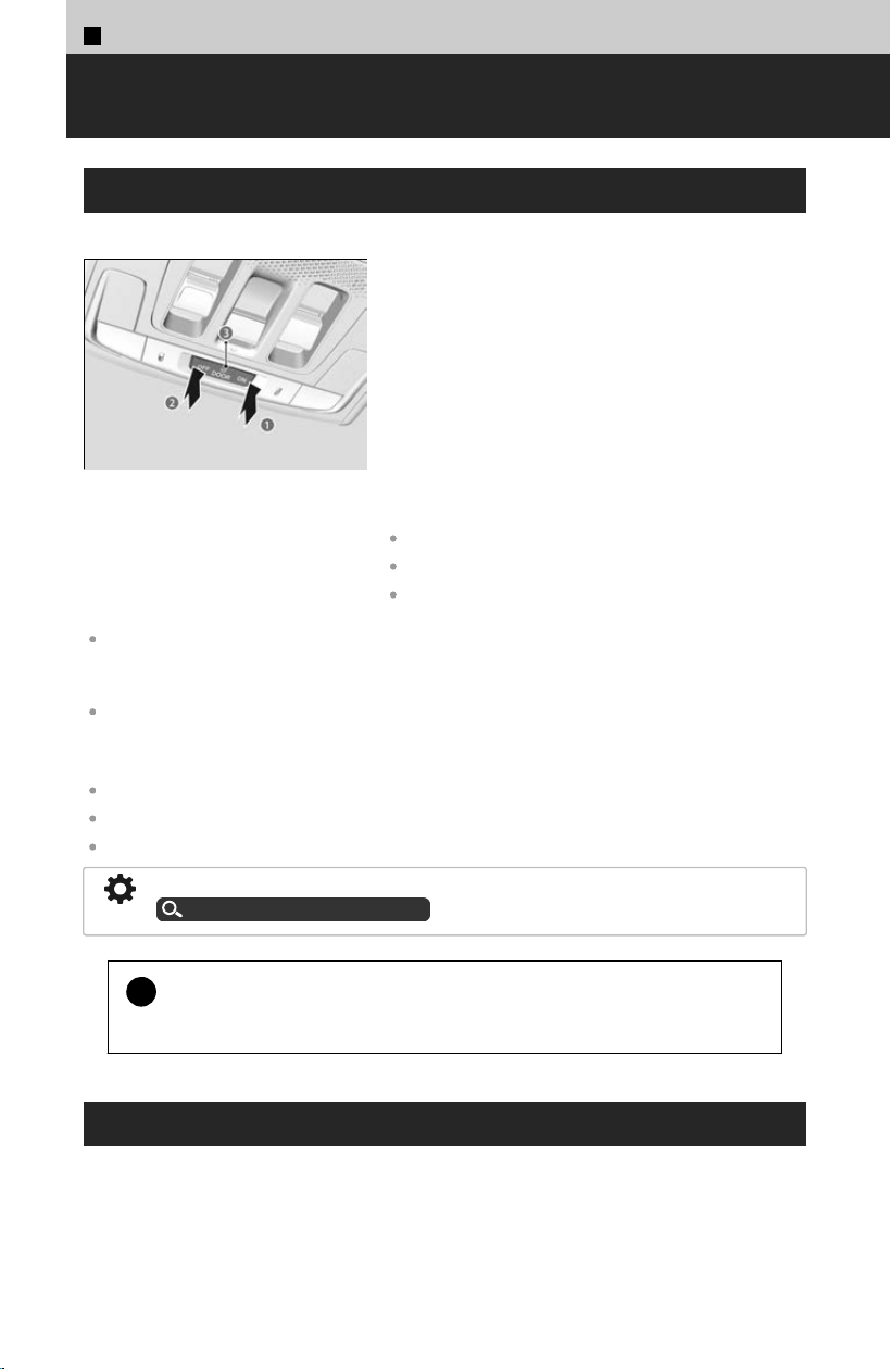
3
Controls >
Interior Lights
Interior Light Switches
a ON
The int
erior lights come on regardless of whether
the doors and tailgate are open or closed.
b OFF
The interior lights remain off regardless of
whether any doors or the tailgate is open or
closed.
c Door activated
The interior lights come on in the following
situations:
When any doors or the tailgate is opened.
When the driver’s door is unlocked.
When the power mode is set to VEHICLE OFF.
In the door activated position, the interior lights turn off about 30 seconds after the doors are
closed. When you unlock the driver’s door but do not open it, the lights turn off after about 30
seconds.
If you leave any of the doors or tailgate open in VEHICLE OFF mode, the interior lights go off
after about 15 minutes.
The interior lights turn off immediately in the following situations:
When you lock the driver’s door.
When you set the power mode to ON.
When you close the driver’s door in ACCESSORY mode.
You can change the interior lights dimming time.
Customized Features
u
P.239
!
To avoid draining the 12-volt battery, do not leave the interior light on
f
or an extended length of time when the engine is off.
Map Light Switches
This light is used for situations such as viewing a map at night while your vehicle is
s
topped.
Press the switch to turn on the light, and press it again to turn off the light.
174
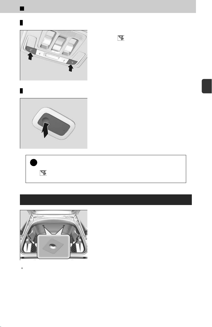
Front seat
The map lights can be turned on and off by
pressing the button.
Rear seat
The map lights can be turned on and off by
pressing the lenses when the front interior light
switch is in the door activated position or ON
position.
!
When the interior light switch is in the door activated position and any
door is open, the fr
ont map lights will not go off when you press the
button.
Cargo Area Light
The cargo area light comes on when you open the
tailgate.
The cargo area light does not have an on/off switch. If the tailgate is left open for an extended
period of time, the lights automatically turn off after 30 minutes.
3
Controls > Interior Lights
175
3
Controls
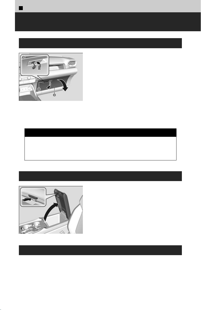
3
Controls >
Interior Convenience Items
Glove Box
a Handle
b Glove Box
c To lock
Pull the handle to open the glove box.
You can lock the glove box with the built-in key.
3 WARNING
An open glove box can cause serious injury to your passenger in a crash,
e
ven if the passenger is wearing the seat belt.
Always keep the glove box closed while driving.
Center Console Box
Press the button to open the console
compartment.
Accessory Power Sockets
The accessory power sockets can be used when the power mode is in ACCESSORY or
ON. Open the c
over to use it.
The accessory power socket is designed to supply power for 12-volt DC accessories
that are rated 180 watts (15 amps) or less.
176
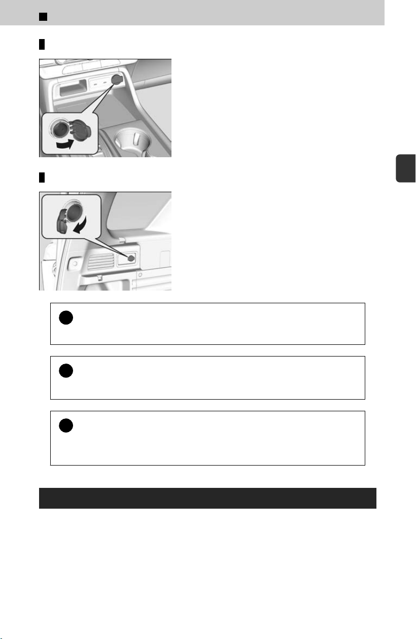
Console panel
Cargo area
*
!
Do not insert an automotive–type cigarette lighter element.
This can o
verheat the accessory power socket.
!
To prevent 12-volt battery drain, only use the accessory power socket
with the engine running
.
!
When the accessory power socket is not in use, close the cover to
pr
event any small foreign objects from getting into the accessory
power socket.
AC Power Outlet
*
Open the cover to use it. Plug in the appliance slightly, turn it 90° clockwise, then
push it al
l the way.
The AC power outlet can be used when the engine is running.
The AC power outlet is designed to supply power for up to 115 volt appliances that
ar
e rated 150 watts or less.
*: Not available on all models
3
Controls > Interior Convenience Items
177
3
Controls
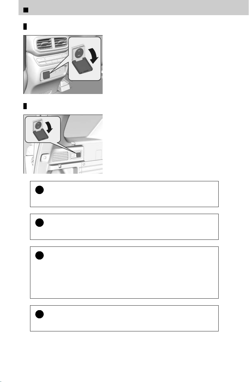
Back of the console compartment
Cargo area
!
When the AC power outlet is not in use, close the cover to prevent any
smal
l foreign objects from getting into the AC power outlet.
!
Continued use of any electric appliance/device exceeding these
r
atings may result in damage to the appliance/device.
!
Do not use the AC power outlet for electric appliances that require
high initial peak w
attage, such as cathode-ray tube type televisions,
refrigerators, electric pumps, etc. It is not suitable for devices that
process precise data, such as medical equipment, and that require an
extremely stable power supply, such as microcomputer-controlled
electric blankets, touch sensor lamps, etc.
!
When both AC power outlets are being used, the combined power
r
ating of the AC power outlets should not exceed 150 watts.
3
Controls > Interior Convenience Items
178
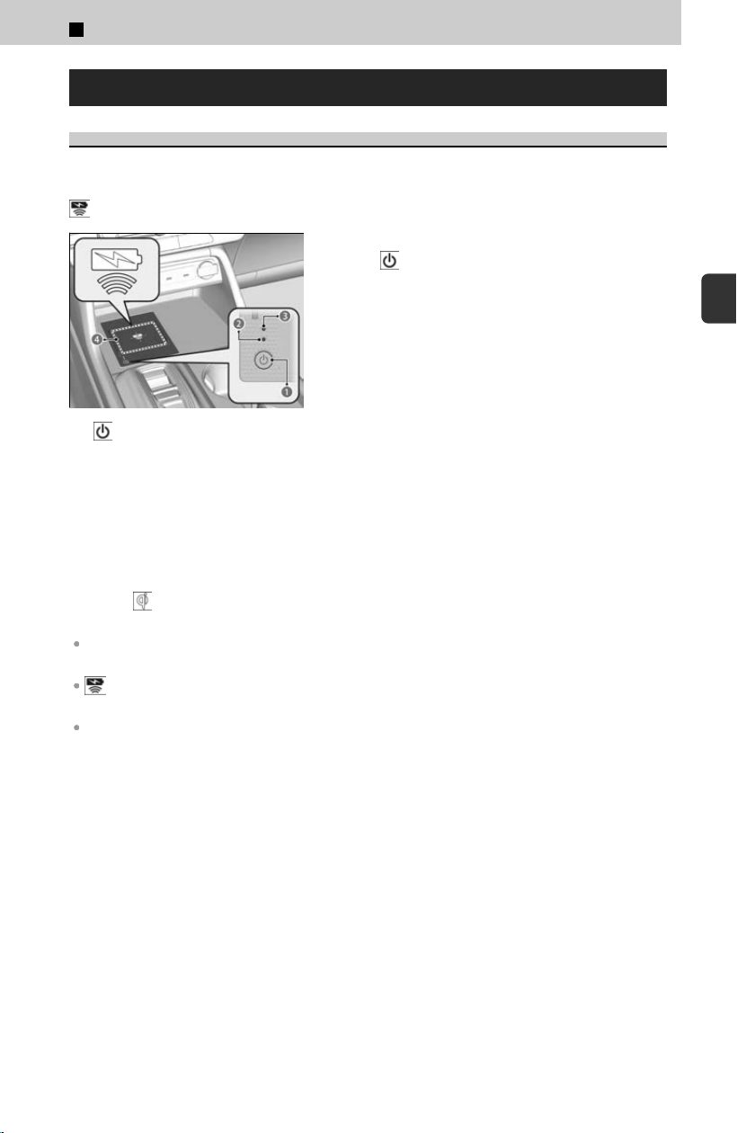
Wireless Charger
About Wireless Charger
To use the wireless charger, the power mode must be in ACCESSORY or ON.
Charge any devices compatible with Qi wireless charging on the area indicated by the
mark as follows:
a (Power) Button
b Green Indicator
c Amber Indicator
d Charging Area
[1] To turn the system on and off, press andhold
the
(power) button.
≫
When the system is activated, the
green indicator light comes on.
[2] Place the device you want to charge on
the char
ging area.
≫
The system will automatically start charging the
device, and the amber indicator light will come
on.
≫
Make sure that the device is compatiblewith
the system, and placed with the chargeable side
in the center of the charging area.
[3] When charging is completed, the green
indicat
or light will come on.
≫
Depending on the device, the amber indicator
light will stay on.
“Qi” and
marks are the registered trademarks owned by Wireless Power
Consortium (WPC).
The wireless charger can support up to 15 W, but the charging rate varies based on the device
and other conditions.
appears on the audio/information screen when the device is being charged by the
wireless charger.
During the charging phase, it is normal for the charging area and the device to heat up.
Charging may be briefly interrupted when:
• All doors and the tailgate are closed to avoid interference with the proper
functioning o
f the keyless access system.
In the following cases, charging may stop or not start:
• The device is already fully charged.
• The temperature of the device is extremely high while charging.
• You are at a place that emits strong electromagnetic waves or noises, such as a TV
station, electric power plant, or gas station.
• The device has a cover, case, or accessories which are not compatible with wireless
charging.
3
Controls > Interior Convenience Items
179
3
Controls
3 CAUTION
Metal objects between the charge pad and the device to be
char
ged will get hot and can burn you.
Always remove foreign objects from the charge pad before charging
the device.
Be sure the surface is clear of dust and other debris before charging.
Do not spill liquids (e.g., water, drinks, etc.) on the charger and the
device.
Do not use oil, grease, alcohol, benzine, or thinner for cleaning the
charge pad.
Do not cover the system with towels, clothing, or other objects while
charging.
Avoid spraying aerosols which may come in contact with the charge
pad surface.
!
This system consumes a lot of power. Do not use the system for a long
period o
f time when the engine is not running. This may weaken the
12-volt battery, making it difficult to start the engine.
!
When using the wireless charger, check the user’s manual that came
with the c
ompatible device you want to charge.
!
Do not place any magnetic recording media or precision machines
within the char
ge area while charging. The data on your cards such as
credit cards can be lost because of the magnetic effect. Also, precision
machines such as watches can be affected.
!
Do not charge more than one device at a time on a charging area.
Indicator is Blinking
Perform one of the following solutions:
When the Indicators (Green & Amber) Blink simultaneously
≫
Remove the obstacle(s).
≫
Pick up and reset the device to the center of the charging area where is located.
≫
Temporarily suspend charging the device. Wait for the temperature to drop and attempt to
charge the device again.
3
Controls > Interior Convenience Items
180
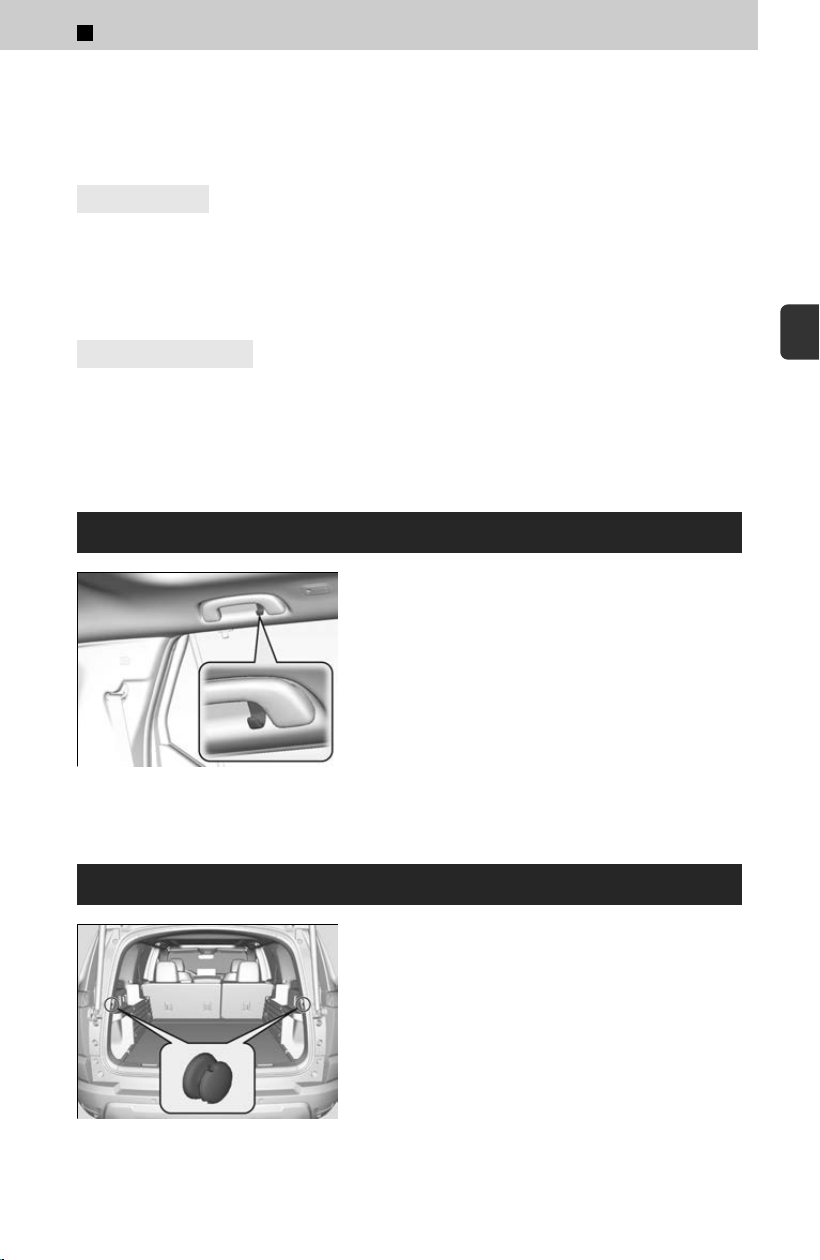
When Indicator (Amber) is Blinking
≫
Contact a dealer for repairs.
RF Radiation Exposure Statement:
4
U.S. models
This equipment complies with FCC RF Radiation exposure limits set forth for an
unc
ontrolled environment.
This device and its antenna must not be co-located or operating in conjunction with
any other antenna or transmitter.
4
Canadian models
This equipment complies with ISED RF Radiation exposure limits set forth for an
unc
ontrolled environment.
This device and its antenna must not be co-located or operating in conjunction with
any other antenna or transmitter.
Coat Hooks
There is a coat hook on the rear grab handle on
both sides.
The coat hooks are not designed for large or heavy items.
Cargo Hooks
Use the cargo hooks to secure cargo in the cargo
area.
3
Controls > Interior Convenience Items
181
3
Controls
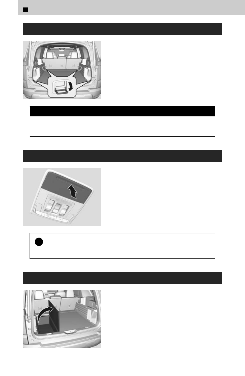
Tie-Down Anchors
The tie-down anchors on the cargo area floor can
be used to install a net for securing items.
3 CAUTION
Do not let anyone access items in the cargo area while driving. Loose items
can cause injur
y if you have to brake hard.
Sunglasses Holder
To open the sunglasses holder, press and release
the indent. To close, press it again until it latches.
You can store sunglasses and other small items in
this holder.
!
Keep the holder closed while driving except when accessing stored
it
ems.
Under-Floor Storage Area
Pull up the cargo floor lid.
3
Controls > Interior Convenience Items
182
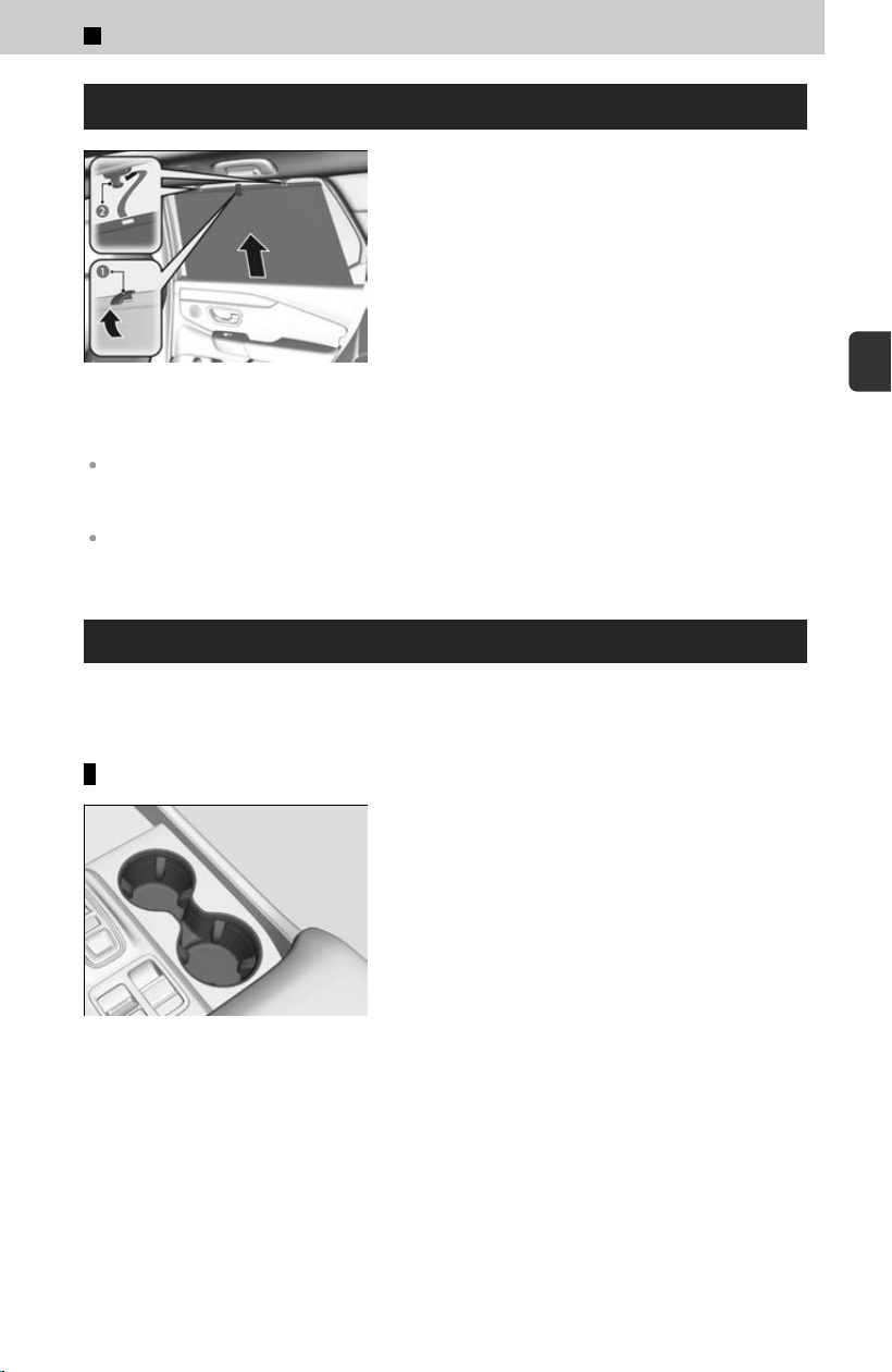
Rear Door Sunshades
*
a Tab
b Hook
Pull the tab and roll up the sunshade all the way.
Use the hook
s to hang it.
Use the sunshades only when the windows are fully closed. Using the shade while a window is
open can unhook and blow off the shade, hitting and possibly hurting anyone sitting near the
window.
To store the sunshade, hold the tab and slowly retract the sunshade. Do not pull the sunshade
in directions other than upward.
Beverage Holders
Spilled liquids can damage the upholstery, carpeting, and electrical components in
the int
erior.
Front seat beverage holders
Located in the console between the front seats.
*: Not available on all models
3
Controls > Interior Convenience Items
183
3
Controls
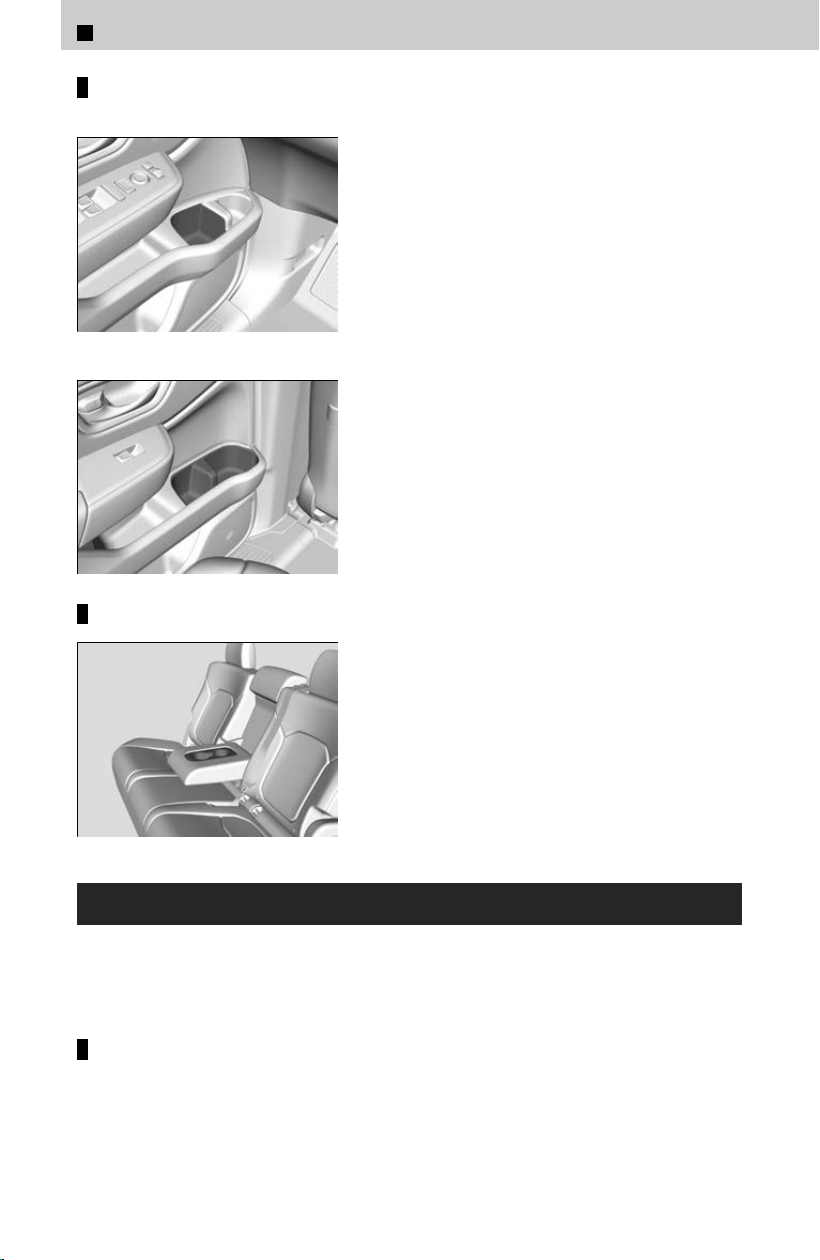
Door side beverage holders
Front
Rear
Located on both of the front and rear door side
pockets.
Rear seat beverage holders
Fold the armrest down to use the rear seat
beverage holders.
HomeLink® Universal Transceiver
*1
The HomeLink® Universal Transceiver can be programed to operate up to three
r
emote controlled devices around your home, such as garage doors, lighting, or home
security systems.
Important safety precautions
Refer to the safety information that came with your garage door opener to test that
the saf
ety features are functioning properly.
If you do not have the safety information, contact the manufacturer.
3
Controls > Interior Convenience Items
184
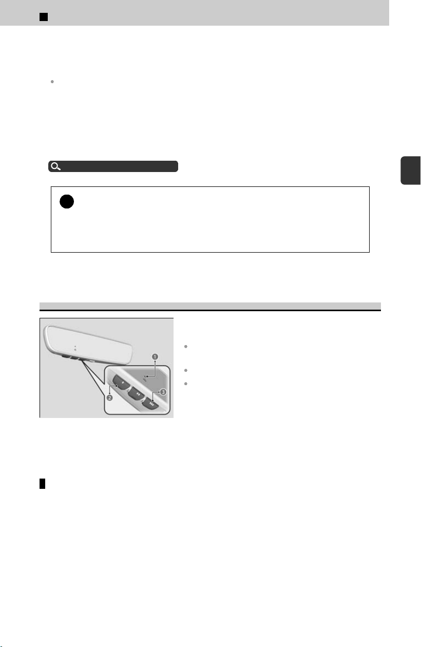
Before programming HomeLink®, make sure that people and objects are out of the
way of the garage or gate to prevent potential injury or damage.
When programming a garage door opener, park just outside the garage door’s path.
Before programming HomeLink® to operate a garage door opener, confirm that the opener
has an external entrapment protection system, such as an “electronic eye,” or other safety
and reverse stop features. If it does not, HomeLink® may not be able to operate it.
HomeLink® will not operate when the vehicle security is set or about 30 minutes
af
ter the power mode is set to VEHICLE OFF. If HomeLink® indicator (LED) does not
show when a button is pressed, ensure doors are unlocked or the power mode is
set to ACCESSORY or ON to return HomeLink® to operation.
Security System Alarm
u
P.49
!
Some LED lightbulbs installed in the garage door opener can interfere
with the tr
aining and consistent operation of your HomeLink® device.
Please consider use of Low RF interference bulbs in your garage door
opener.
*1: Models with optional HomeLink®
Training HomeLink®
a Indicator
b I HomeLink® Button
c III HomeLink® Button
If it is necessary to erase all previously entered
learned c
odes:
Press and hold the I and III HomeLink® buttons for
about 10 seconds, until the green indicator blinks.
Release the buttons to finish.
If you wish to train a new learned code, go directly to
the Programming a Button section.
Programming a button
These instructions should work for most gate or garage openers, but may not work
f
or all. For detailed instructions about your specific remote opener, visit http://
www.homelink.com or call (800) 355-3515.
[Preparation] Clear the area around the device (garage door). For best results, use
fresh batteries in existing remote transmitter and park vehicle close to garage door.
Review all steps before starting as some steps are time sensitive.
[1] Hold the remote transmitter you wish to link 1 to 2 inches (3 - 5 cm) from the
HomeLink
® button you want to program.
3
Controls > Interior Convenience Items
185
3
Controls

[2] Press the desired HomeLink® button. The HomeLink® indicator (LED) will
slowly flash orange, if not see the Reprogramming a Button or Erasing
Button Memory sections.
[3] While the HomeLink® indicator (LED) is slowly flashing orange, press and hold
the button on the existing remote transmitter (Some garage doors may require
you to press, hold and release the button on the remote every 2 secs). Within
60 seconds the HomeLink® indicator (LED) will change to rapidly flashing
green or continuously on green.
[4] Press, hold for 2 seconds, and release the programed HomeLink® button 3
times.
Did the device (garage door opener) operate?
YES
Training Complete
NO
[5] Press and hold the HomeLink® button again, notice the HomeLink® indicator
(LED).
HomeLink® indicat
or (LED) is continuously on green.
[6] Press and hold the HomeLink® button again. The device (garage door opener)
should oper
ate.
Training Complete
If the device does NOT operate, complete the R
eprogramming a Button or Erasing
Button Memory sections and then start at Step [1] again. If programming continues
to fail, please visit http://www.homelink.com or call (800) 355-3515.
HomeLink® indicator (LED) rapidly flashes green.
[6] Your device (garage door opener) will need to synchronize with HomeLink®.
L
ocate the learn button (may be labeled as program, smart, or similar) on the
device’s main body (e.g. garage door opener motor). Only once you have
located the button should you proceed to the next step, as it is time sensitive.
Reference the device user manual for the exact location of the button if
needed.
[7] Press the learn button on the device (garage door opener) and within 30
seconds return to your vehicle to press and release the programed HomeLink®
button 3 times at 2 second intervals. The device (garage door opener) should
operate.
Training Complete
3
Controls > Interior Convenience Items
186

If the device does NOT operate, complete the Reprogramming a Button or Erasing
Button Memory sections and then start at Step [1] again. If programming continues
to fail, please visit http://www.homelink.com or call (800) 355-3515.
Reprogramming a button
If you want to retrain a programed button for a new device, you do not have to
er
ase all button memory. You can replace the existing memory code using this
procedure:
[1] Press and hold the desired HomeLink® button until the HomeLink® indicator
begins t
o slowly flash orange. This should take about 20 seconds.
[2] Release the HomeLink® button and position the remote transmitter you wish
to link 1 - 3 inches (3 - 8 cm) from the HomeLink® button you want to
program, then follow steps 3 - 6 under “programming a button.”
Erasing button memory
To erase programming from the buttons, press and hold the two outside HomeLink®
but
tons until the HomeLink® indicator changes from orange to rapidly flashing
green. This should take about 10 seconds. You should erase all programming
before selling the vehicle.
Operating
To operate, simply press and release the programed HomeLink® button. Activation
wil
l now occur for the trained device.
Questions
For questions or comments, visit ht
tps://www.HomeLink.com, https://
www.youtube.com/HomeLinkGentex, or by calling the HomeLink® Hotline (North
America only) at (800) 355-3515.
HomeLink® is a registered trademark of Gentex Corporation.
3
Controls > Interior Convenience Items
187
3
Controls
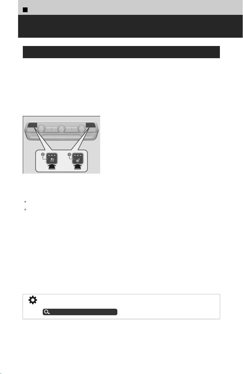
3
Controls >
Seat Heaters/Ventilators
Using the Front Seat Heaters/Ventilators
*
The seat heaters or ventilators can be used when the power mode is in ON.
The seat heaters:
Use them to warm up the seat.
The seat ventilators:
Use them when you want to ventilate the surface of the seats.
When used with the air conditioning, the surface of the seats will become easier to
c
ool.
a Seat Heater Button
b Seat Ventilator Button
Press the seat heater or the seat ventilator
but
ton:
Once - The HI setting (three indicators on)
Twice - The MID setting (two indicators on)
Three times - The LO setting (one indicator on)
Four times - The OFF setting (no indicators on)
When the power mode is turned on after it is turned off, the previous setting is maintained.
After a certain period of time, the strength setting for the seat heaters will automatically be
reduced by one level at a time until the seat heaters shuts off. The elapsed time varies
according to the interior environment.
Press the AUTO button:
Both the air conditioner and seat temperature will automatically change to the setting
mos
t suitable to the ambient environment.
≫
When the seat heater or the seat ventilation button is pressed, settings will switch to manual
mode.
As time passes, the set temperature will fall, and eventually the seat heater will shut
o
ff.
The seat heater and seat ventilation may turn on if sensors detect weight on the
passenger seat due to cargo, etc.
To prevent automatic activation, you can turn off automatic climate control for the
front seat.
Customized Features
u
P.239
*: Not available on all models
188
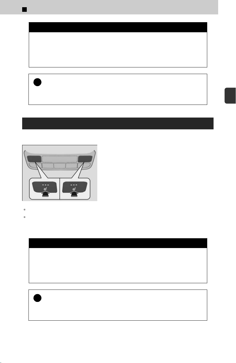
3 WARNING
Heat induced burns are possible when using seat heaters.
P
ersons with a diminished ability to sense temperature (e.g., persons with
diabetes, lowerlimb nerve damage, or paralysis) or with sensitive skin
should not use seat heaters.
!
Do not use the seat heaters and the seat ventilator even in LO when
the engine is o
ff. Under such conditions, the 12-volt battery may be
weakened, making the engine difficult to start.
Using the Rear Seat Heaters
*
The seat heaters can be used when the power mode is in ON.
Press the seat heater button:
Once - The HI setting (three indicators on)
Twice - The MID setting (two indicators on)
Three times - The LO setting (one indicator on)
Four times - The OFF setting (no indicators on)
There is no heater in the rear center seating position.
After a certain period of time, the strength setting for the seat heaters will automatically be
reduced by one level at a time until the seat heater shuts off. The elapsed time varies
according to the interior environment.
3 WARNING
Heat induced burns are possible when using seat heaters.
P
ersons with a diminished ability to sense temperature (e.g., persons with
diabetes, lowerlimb nerve damage, or paralysis) or with sensitive skin
should not use seat heaters.
!
Do not use the seat heaters even in LO when the engine is off. Under
such c
onditions, the 12-volt battery may be weakened, making the
engine difficult to start.
*: Not available on all models
3
Controls > Seat Heaters/Ventilators
189
3
Controls
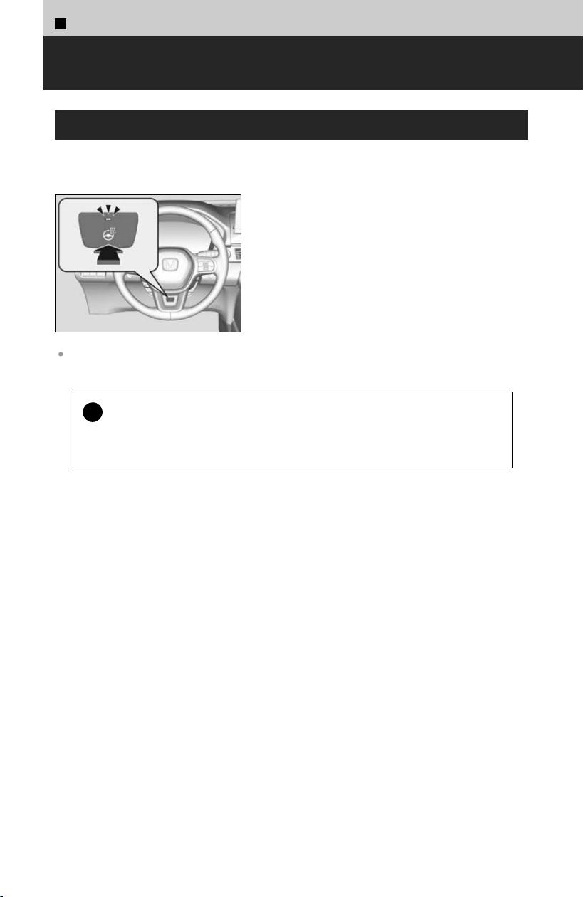
3
Controls >
Heated Steering Wheel
*
Using the Heated Steering Wheel
The heated steering wheel can be used when the power mode is in ON.
When a comfortable temperature is reached, press the button again to turn it off.
Press the button on the lower side of the steering
wheel.
The heated steering wheel is turned off every time you start the engine, even if you turned it
on the last time you drove the vehicle.
!
Do not use the heated steering wheel continuously when the engine is
o
ff. Under such conditions, the 12-volt battery may be weakened,
making the engine difficult to start.
*: Not available on all models
190
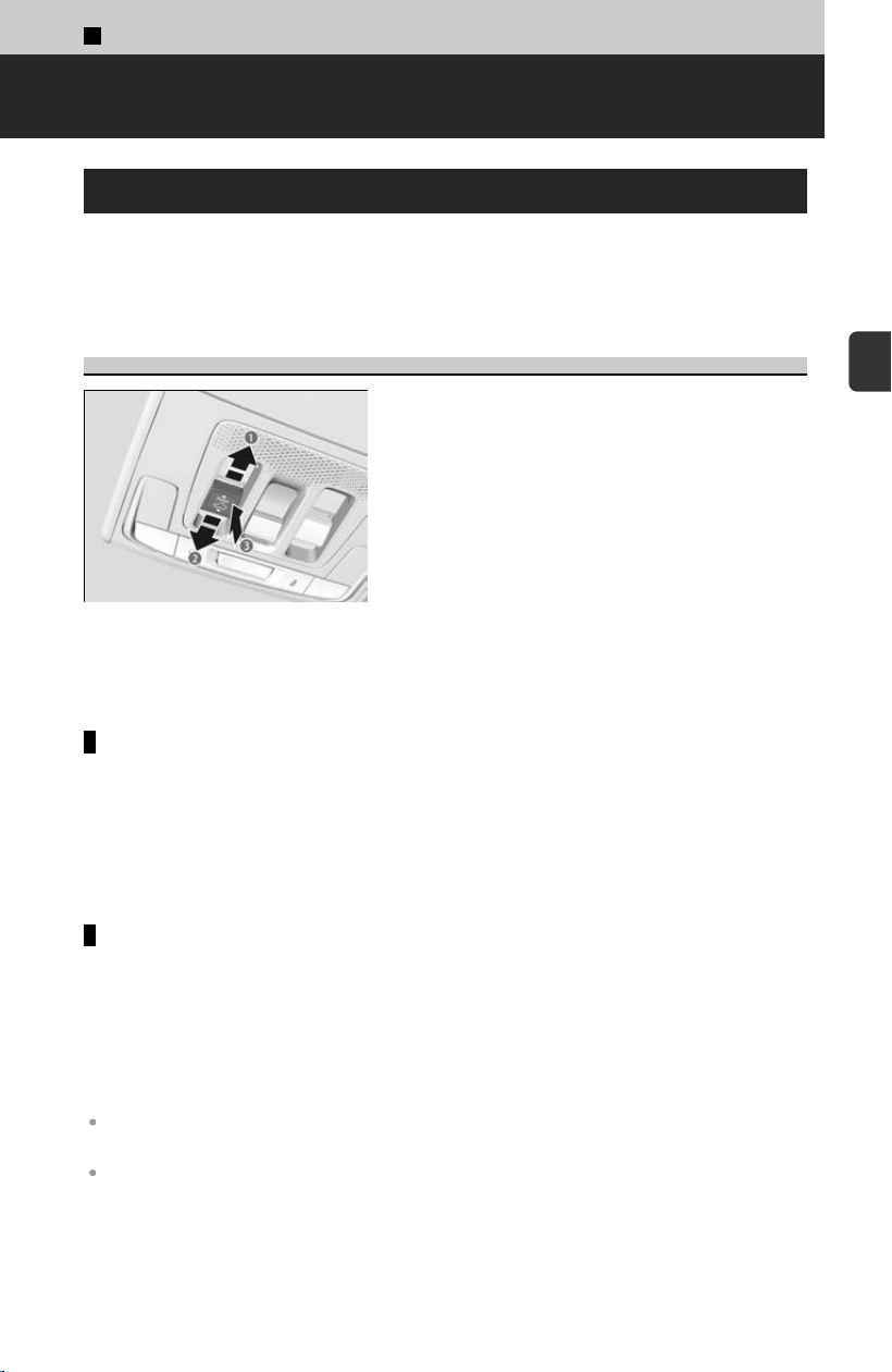
3
Controls >
Panoramic Roof
*
Opening/Closing the Panoramic Roof
You can operate the panoramic roof and sunshade when the power mode is in ON.
Use the s
witch in the front of the ceiling to open and close the panoramic roof and
sunshade.
Using the Panoramic Roof Switch
a Open
b Close
c Tilt
To open/close
To open: Pull the switch back.
To close: Push the switch forward.
≫
If you pull/push the switch firmly, the panoramic roof will open/close automatically. If you
lightly operate the switch while the panoramic roof is opening/closing automatically, it will
stop midway.
Tilting the panoramic roof up
To tilt: Push the switch up.
≫
The sunshades will open automatically, and the panoramic roof will start to tilt up.
To close: Push the switch forward firml
y to automatically close the panoramic roof.
≫
If you lightly push the switch forward, the panoramic roof will stop at the position where you
release it.
Whenever the panoramic roof is opening, the sunshade moves along with it.
However, when the panoramic roof is closing, the sunshade does not move.
The panoramic roof and sunshade can be operated for up to 10 minutes after you set the
power mode to VEHICLE OFF.
Opening either front door cancels this function.
*: Not available on all models
191
3
Controls
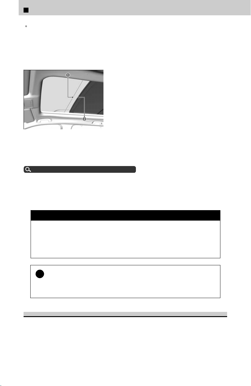
When you tilt open the panoramic roof, the sunshade opens slightly to let in fresh air.
When you close the panoramic roof from this position, the sunshade returns to its closed
position.
The panoramic roof cannot be fully opened in a single operation. The panoramic roof
has a “
comfort” position or wind noise reduction position at which the roof first stops.
To open fully, pull the switch back again after the roof has stopped at this position.
a Comfort Position
b Full Open Position
You can use the remote transmitter to operate the panoramic roof.
Opening the Windows with the Remote
u
P.84
When you tilt open or slide open the panoramic roof, if the climate control is set to
A
UTO it will automatically switch to fresh air mode to reduce wind noise. When you
close the panoramic roof, depending on the situation it will change to recirculation or
fresh air mode.
3 WARNING
Opening or closing the panoramic roof and sunshade on someone’s hands
or fing
ers can cause serious injury.
Make sure all hands and fingers are clear of the panoramic roof and
sunshade before opening or closing it.
!
Opening the panoramic roof in below freezing temperature or when it
is c
overed with snow or ice can damage the panoramic roof panel or
motor.
Using the Sunshade Switch
The sunshade can be opened or closed to adjust the amount of light that enters the
cabin.
3
Controls > Panoramic Roof
*
192

a Open
b Close
To open/close
To open: Pull the switch back.
To close: Push the switch forward.
≫
If you pull/push the switch firmly, the sunshade will open/close automatically. If you lightly
operate the switch while the sunshade is opening/closing automatically, it will stop midway.
When you use the sunshade switch to open the sunshade, the panoramic roof does not
move.
The sunshade cannot be fully closed if the panoramic roof is open.
When you close the sunshade with the panoramic roof open, the sunshade stops slightly
before the panoramic roof.
When you push the switch forward again, the sunshade and the panoramic roof close
together.
What to Do If
When the panoramic roof does not close
When resistance is detected, the auto reverse function causes the panoramic roof
and sunshade t
o change directions, then stop.
Auto reverse stops sensing when the panoramic roof and sunshade are almost
closed to ensure that it fully closes.
Make sure that all objects, including fingers, are clear of the panoramic roof and
sunshade.
3
Controls > Panoramic Roof
*
193
3
Controls
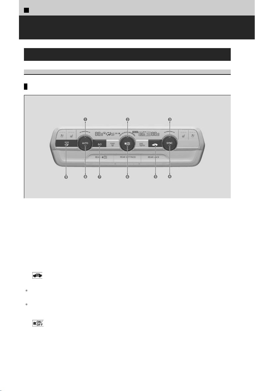
3
Controls >
Climate Control System
Automatic Climate Control System
About Automatic Climate Control System
Explanations of switches
a Driver’s Side Temperature Control Dial
Adjusts the interior temperature.
b Fan Control Dial
Adjusts the fan speed.
c Passenger’s Side Temperature Control Dial
Adjusts the interior temperature.
d SYNC (Synchronization) Button
e
(Recirculation) Button
Switch Recirculation mode/Fresh air mode.
Recirculation (indicator light on):
Recirculates air from the vehicle’s interior through the system.
Fresh air (indicator light off):
Maintains outside ventilation. Keep the system in fresh air mode in normal situations.
f
(ON/OFF) Button
Switch ON/OFF of the climate control system.
g A/C (Air Conditioning) Button
Switch ON/OFF of cooling/dehumidification function.
194
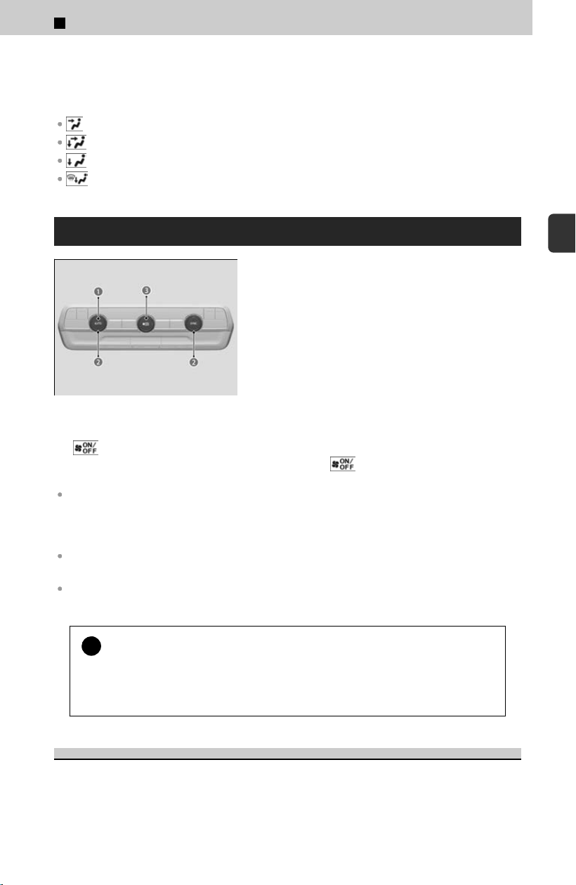
h AUTO Button
Switch to automatic control.
i MODE Control Button
Dashboard vents and back of the console compartment
Dashboard and floor vents, and back of the console compartment
Floor vents
Floor and windshield defroster vents
Using Automatic Climate Control
a AUTO Button
b Temperature Control Dial
c
(ON/OFF) Button
The automatic climate control system maintains
the int
erior temperature you select.
The system also selects the proper mix of heated
or cooled air that raises or lowers the interior
temperature to your preference as quickly as
possible.
Use the system when the engine is running.
[1] Press the A
UTO button.
[2] Adjust the interior temperature using the
driver’s side or passenger’s side
temperature control dial.
[3] Press the (ON/OFF) button to cancel.
If any buttons are pressed while using the climate control system in auto, the function of the
button that was pressed will take priority.
The AUTO indicator will go off, but functions unrelated to the button that was pressed will be
controlled automatically.
While ECON mode is active, the climate control system may have reduced cooling
performance.
To prevent cold air from blowing in from outside, the fan may not start immediately when the
AUTO button is pressed.
!
If the interior is very warm, you can cool it down more rapidly by
par
tially opening the windows, turning the system on auto, and setting
the temperature to low. Change the fresh air mode to recirculation
mode until the temperature cools down.
Synchronization Mode
You can set the temperature synchronously for the driver’s side, passenger’s side,
and r
ear in synchronization mode.
3
Controls > Climate Control System
195
3
Controls
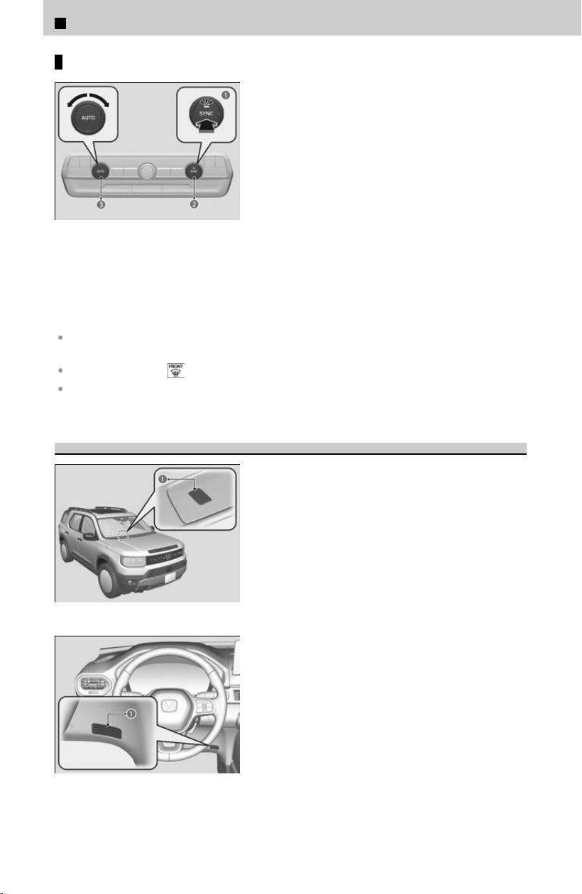
Using synchronization mode
a SYNC Button
b Passenger’s Side
Temperature Control Dial
c Driver’s Side Temperature
Control Dial
[1] Press the S
YNC button.
≫
The SYNC indicator will come on.
≫
The system switches to synchronization mode.
[2] Adjust the temperature using the driver’s
side t
emperature control dial.
Press the SYNC button, adjust the interior temperature using the passenger’s side
temperature control dial or changing the rear temperature to return to dual mode.
When you press the button, the system changes to synchronization mode.
When the system is in dual mode, the driver’s side temperature, the passenger’s side
temperature, and the rear temperature can be set separately.
Automatic Climate Control Sensors
a Sensor
a Sensor
The automatic climate control system is equipped
with sensors
. Do not cover or spill any liquid on
them.
3
Controls > Climate Control System
196
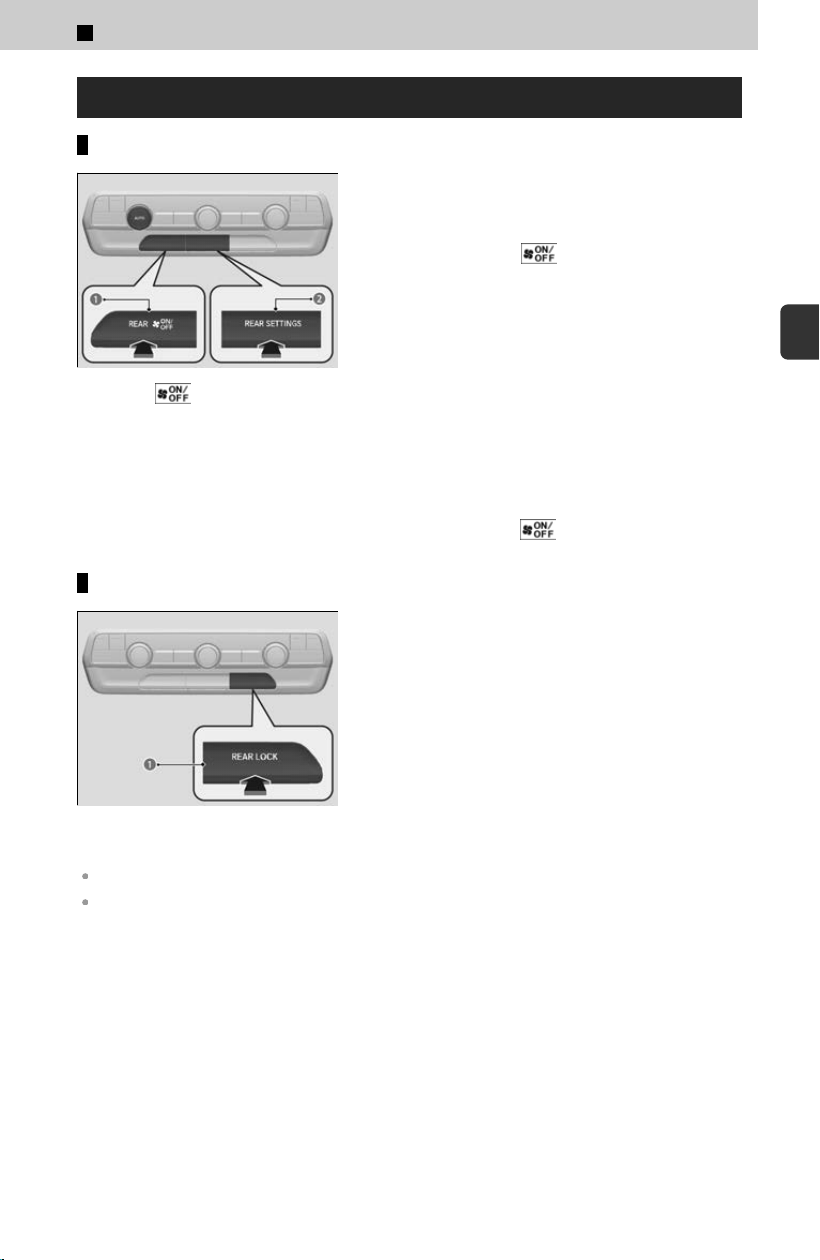
Rear Climate Control System
Using the rear climate control system from the front panel
a REAR (ON/OFF) Button
b REAR SETTINGS Button
Use the system when the engine is running and
the climat
e control system is operating.
[1] Press the REAR
(ON/OFF) button.
[2] Press the REAR SETTINGS button.
≫
The system switches to the rear control mode
for 10 seconds. The REAR indicator appears on
the display.
[3] Press the A
UTO button.
≫
The rear system changes to AUTO mode.
≫
The system automatically adjusts the fan speed
and airflow levels to maintain the set rear
temperature. Change the temperature if
necessary.
[4] To turn off the rear climate control system,
pr
ess the REAR (ON/OFF) button.
Using the rear lock mode
*
a REAR LOCK Button
Press the REAR L
OCK button to turn the rear lock
mode on and off.
While the rear lock mode is on, the rear control
panel is disabled.
≫
The LOCK indicator will come on.
LOCK appears on the rear control panel while the rear lock is on.
If the rear lock is on while in SYNC mode, the rear control panel is disabled. SYNC LOCK
appears on the rear control panel.
*: Not available on all models
3
Controls > Climate Control System
197
3
Controls
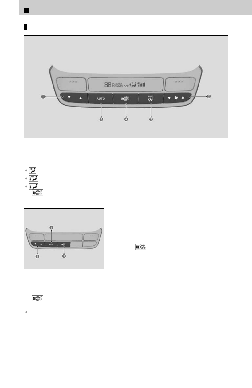
Using the rear climate control system from the rear panel
*
a Rear Temperature Control Buttons
b Rear Fan Control Buttons
c MODE Control Button
Back of the console compartment vents
Back of the console compartment and rear floor vents
Rear floor vents
d
(ON/OFF) Button
e Rear AUTO Button
a Rear AUTO Button
b Rear Temperature Control
Button
c
(ON/OFF) Button
Use the system when the engine is running
[
1] Press the rear AUTO button.
[2] Adjust the interior temperature using the
rear temperature control button.
[3] To turn off the rear climate control system,
press
(ON/OFF) button.
When the rear lock mode is off, the temperature of the rear passenger compartment can be
controlled independently.
*: Not available on all models
3
Controls > Climate Control System
198

3
Controls >
In-Vehicle Infotainment
About Your In-Vehicle Infotainment
The audio system features AM/FM radio. It can also play USB flash drives, iPod,
iPhone
, smartphone, and Bluetooth® devices.
You can operate the audio system from the buttons and knobs on the panel, the
remote controls on the steering wheel, or the icons on the touchscreen interface.
≫
To use this system, the power mode must be in ACCESSORY or ON.
Audio System Theft Protection
The audio system is disabled when it is disconnected from the power source, such as
when the 12-
volt battery is disconnected or goes dead. In certain conditions, the
system may display a code entry screen. If this occurs, reactivate the audio system.
Reactivating the audio system
[1] Startup animation starts in the audio system by opening the door.
[2] Press and hold the VOL/
AUDIO (volume/power) knob for more than two
seconds.
[3] Set the power mode to ON.
≫
The audio system is reactivated when the audio control unit establishes a connection
with the vehicle control unit. If the control unit fails to recognize the audio unit, you
must go to a dealer and have the audio unit checked.
Audio System Basic Operation
To use the audio system feature, the power mode must be in ACCESSORY or ON.
Audio System Basic Operation With 12.3″ Color
Touchscreen
Swiping the screen left or right changes to the next screen.
Select
(Home) icon to go directly back to the first page of the home screen from
any page.
199
3
Controls
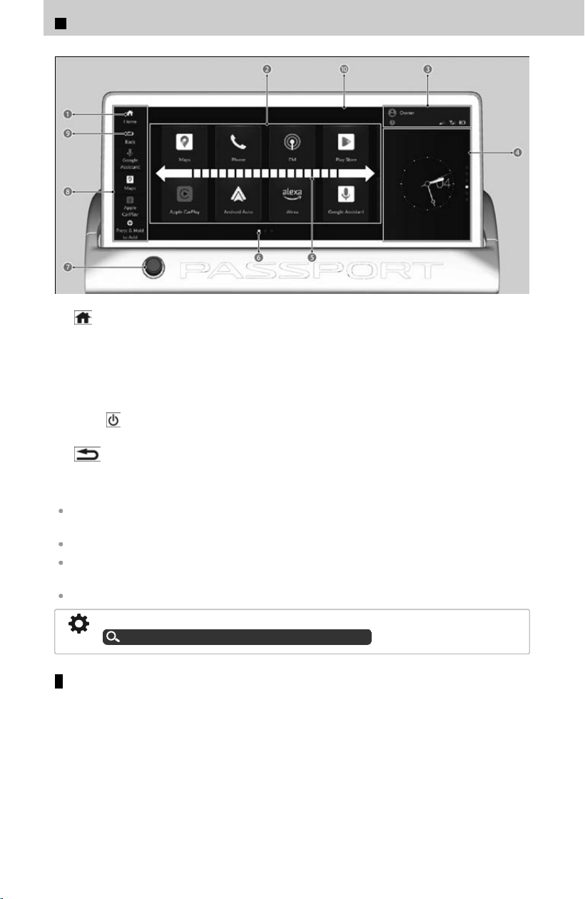
a (Home) Icon
b A-Zone
c Status Bar
d B-Zone
e Swipe
f Current Page Position
g VOL/
AUDIO (Volume/Power) Knob
h Mode Change Switch Bar
i
(Back) icon
j Audio/Information Screen
Touchscreen operation
Use simple gestures - including touching, swiping, and scrolling - to operate certain audio
functions.
Some functions may be limited while driving.
Some items may be grayed-out during driving to reduce the potential for distraction. You can
select them when the vehicle is stopped.
Wearing gloves may limit or prevent touchscreen response.
You can change the touchscreen sensitivity setting.
How to Customize the General Settings
u
P.239
Selecting an audio source
Select application icon in the header area, then select an icon on the source list to
s
witch the audio source.
3
Controls > In-Vehicle Infotainment
200
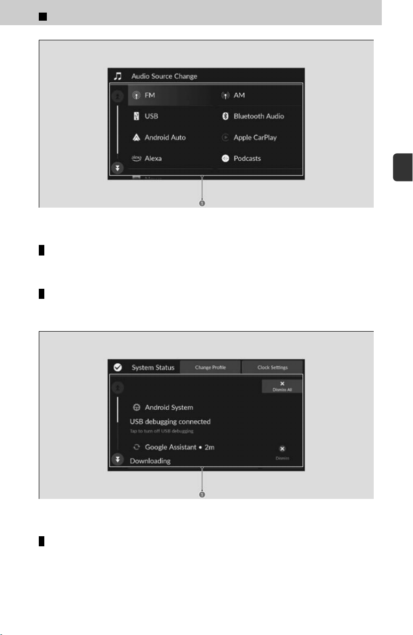
a Source List
A-Zone
The A-Zone is the main operation area in the 12.3″ Color Touchscreen.
Status bar
Displays information about your vehicle and connected devices. You can select the
s
tatus bar to view more details in the status area.
a Status Area
B-Zone
The B-Zone displays a card that is useful while the driver is using another
application in the A
-Zone.
The following cards are available:
3
Controls > In-Vehicle Infotainment
201
3
Controls
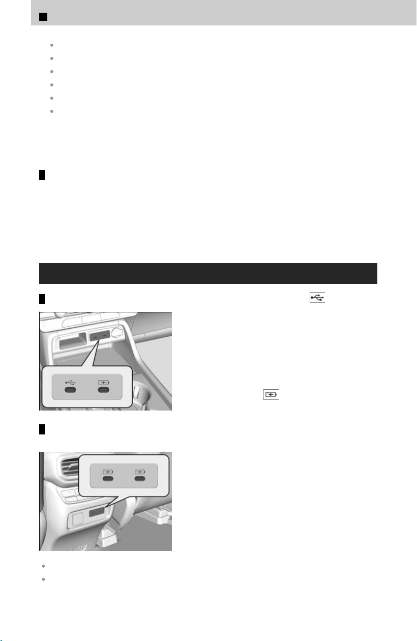
Suggestions from Google Assistant
Audio source
Compass
Clock
Trip Computer
Navigation (Apple CarPlay or Android Auto)
You can swipe up and down on the B-Zone to view a different card.
Page position is indicated at the right of the B-Zone.
Mode change switch bar
You can also select any application from the mode change switch bar. Shortcuts can
be edit
ed to open other applications, but Home, Back, and Google Assistant
*1
or
Alexa
*1
cannot be edited.
*1: Displayed the default assist app.
USB Ports
On the front panel
On the back of the console
compartment
USB charging/connector port ( )
The USB port is for charging devices, playing
audio files, and connecting compatible phones
with Apple CarPlay or Android Auto.
≫
To prevent any potential issues, be sure to use an
Apple MFi Certified Lightning Connector for Apple
CarPlay. The USB cables should be certified by USB-
IF to be compliant with USB 2.0 Standard.
USB charging port (
)
The USB port is only for charging devices.
≫
You cannot play audio files even if an audio device is
connected.
We recommend backing up your data before using the device in your vehicle.
Messages displayed on the Audio System may vary depending on the device model and
software version.
3
Controls > In-Vehicle Infotainment
202
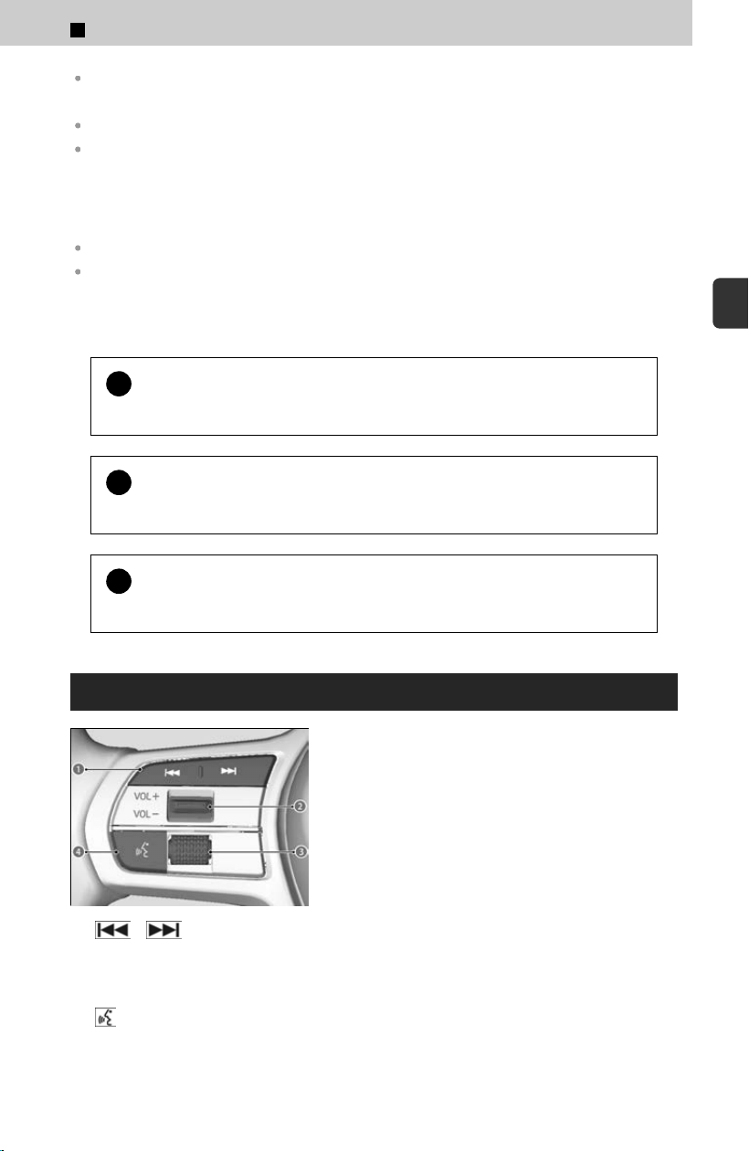
Some devices may not work even if they are connected to the USB ports.
Supplementary information about USB Charging:
The USB port supports USB Power Delivery.
USB standard output
When using 1 port: 5V/3A(15W), 9V/3A(27W), 15V/3A(45W), 20V/3A(60W)
When using both ports: 5V/3A(15W), 9V/3A(27W), 15V/3A(45W), 20V/2.25A(45W), Max 60W
in total
For amperage details, read the operating manual of the device that needs to be charged.
The USB port also supports PPS (Programmable Power Supply). PPS 5.0V-21V (Max 60W).
Charging may not start or may operate slowly depending on the connected devices and
cables.
Using only one port while not connecting anything (including cables) to the other port may
solve the issue.
!
Do not leave the device or USB flash drive in the vehicle. Direct
sunlight and high t
emperatures may damage it.
!
Do not connect the device or USB flash drive using a hub, as they will
not oper
ate if you do.
!
Do not use a device such as a card reader or hard disk drive, as the
de
vice or your files may be damaged.
Audio Remote Controls
a / (Seek/Skip)
Buttons
b VOL+/VOL- (Volume) Switch
c Left Selector Wheel
d
(Talk) Button
Allow you to operate the audio system while
driving
. The information is shown on the driver
information interface.
3
Controls > In-Vehicle Infotainment
203
3
Controls
!
Depending on the device you connect, some functions may not be
av
ailable.
Seek/Skip Buttons
When listening to the radio
Press
: To select the next preset radio station.
Press
: To select the previous preset radio station.
Press and hold
: To select the next strong station.
Press and hold
: To select the previous strong station.
When listening to a wired connection, USB flash drive, Bluetooth® Audio, or Smartphone
Connection
Press : To skip to the next song.
Press
: To go back to the beginning of the current or previous song.
When listening to a USB flash drive
Press and hold
: To skip to the next folder.
Press and hold
: To go back to the previous folder.
VOL+/VOL- (Volume) Switch
Press Up: T
o increase the volume.
Press Down: To decrease the volume.
Left Selector Wheel
To switch between audio modes, roll up or down and then press the left selector
wheel
.
≫
When cycling through the list, audio modes appear in the following order.
Customize display ➔ Back ➔ Phone ➔FM ➔ AM ➔ USB ➔ Bluetooth ➔ Apps (Apple
Carplay/Android Auto) ➔ Alexa
Connecting a Device
With a connected device, you can use Apple Carplay or Android Auto to listen to audio
files
.
≫
Depending on the app used, smartphone battery may decrease even with a wired connection.
!
Always make sure your vehicle is parked in a safe location before
c
onnecting a device.
3
Controls > In-Vehicle Infotainment
204
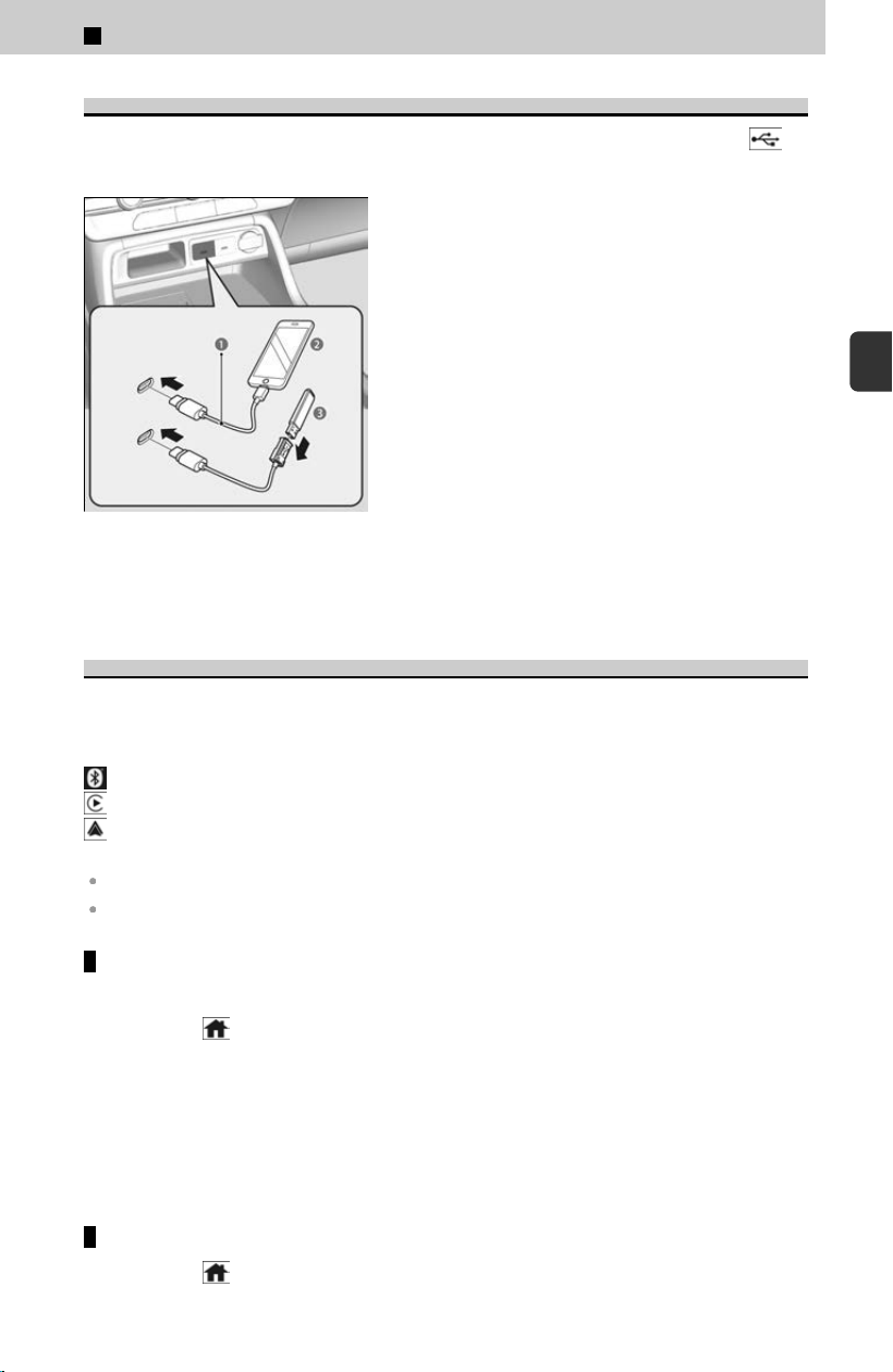
About Wired Connections
Connect a smartphone or USB flash drive to the USB charging/connector port (
).
≫
You may need to operate the smartphone.
a USB Cable
b Device
c USB Flash Drive
About Wireless Connections
You can modify Bluet
ooth® function settings.
Once you have paired a phone, you can see it displayed on the screen with one or
more icons on the right side. These icons indicate the following:
: The phone is compatible with HFL and Bluetooth® Audio.
: The phone is compatible with Apple CarPlay.
: The phone is compatible with Android Auto.
Phone Pairing Tips:
Up to six phones can be paired.
Your phone’s battery may drain faster when it is paired to the system.
Bluetooth® setup
You can turn Bluet
ooth® function on and off.
[1] Select
(Home) icon.
[2] Select General Settings.
[3] Select Connections.
[4] Select Manage Device Connections.
[5] Select Options.
[6] Select Bluetooth, then select On.
[7] Select Yes.
To pair a cell phone (when there is no phone paired to the system)
[1] Select
(Home) icon.
3
Controls > In-Vehicle Infotainment
205
3
Controls

[2] Select General Settings.
[3] Select Connections.
[4] Select Manage Device Connections.
[5] Select + Connect New Device.
[6] Make sure your phone is in search or discoverable mode.
[7] Select Vehicle Name from your phone.
≫
If you want to pair a phone from this audio system, select Search for Devices, and
then select your phone when it appears on the list.
[8] The system gives you a pairing code on the audio/information screen. This
may v
ary by phone.
≫
Confirm if the pairing code on the screen and your phone matches.
≫
If the audio system has not sent the pairing code to your phone, the pairing code
authentication screen will be displayed. Check the pairing code and select Pair.
[9] Select Y
es if you want to set this phone as the preferred connection.
To change the currently paired phone
[1] Select the
(Home) icon.
[2] Select General Settings.
[3] Select Connections.
[4] Select Manage Device Connections.
[5] Select a phone to connect.
≫
HFL disconnects the connected phone and starts searching for another paired phone.
≫
You can set the connected phone priority. Check the box on the phone you want to
prioritize.
[6] Select Bluet
ooth, Apple CarPlay, or Android Auto.
[7] Select Yes.
To pair other phones, select + Connect New Device from the Bluetooth® screen.
To delete a paired phone
[1] Select
(Home) icon.
[2] Select General Settings.
[3] Select Connections.
[4] Select Manage Device Connections.
[5] Select a phone you want to delete.
[6] Select Delete Device.
[7] A confirmation message appears on the screen. Select Delete.
About System Updates
When a software update is available for your vehicle, a notification wil
l be displayed
on the Meter or the Audio information screen.
Instructions for performing updates via the audio information screen are included in
this manual
.
3
Controls > In-Vehicle Infotainment
206

For details on other methods of performing an update, please refer to the HondaLink
manual, or ask a dealer.
System updates that change specifications may result in some discrepancies with the
information in this owner’s manual.
Instructions
System Updates
u
P.210
3
Controls > In-Vehicle Infotainment
207
3
Controls
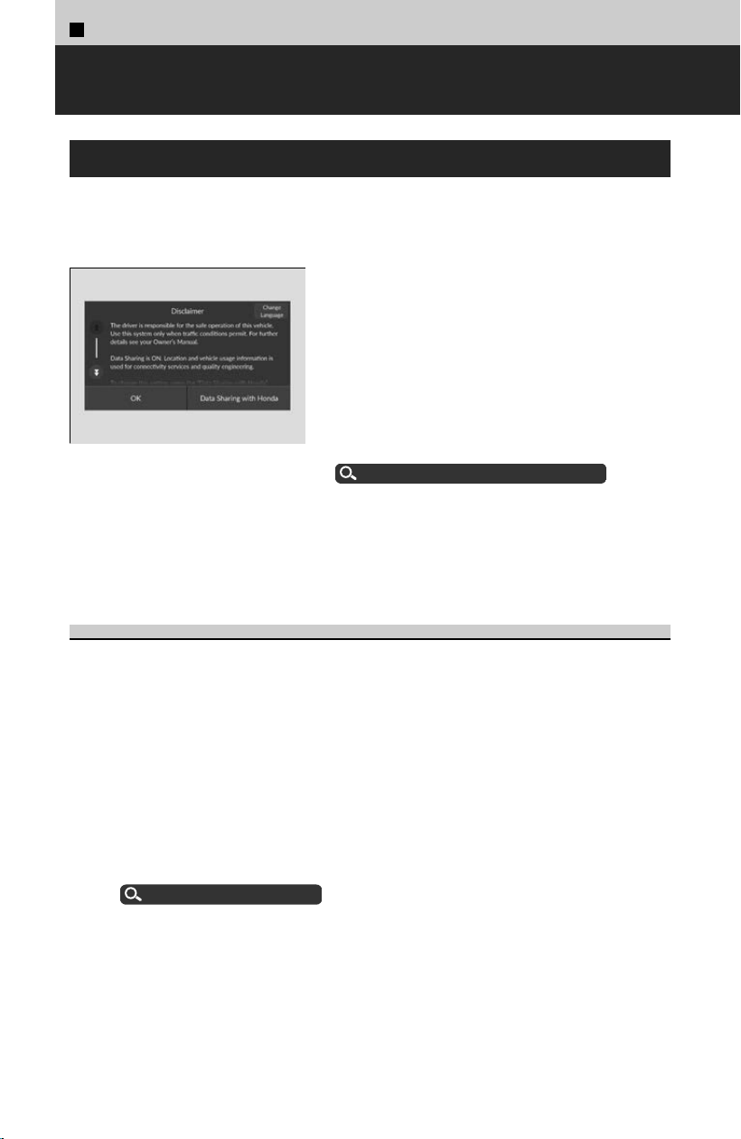
3
Controls >
12.3″ Color Touchscreen
Start Up
The 12.3″ Color Touchscreen starts automatically when you set the power mode to
A
CCESSORY or ON. At start-up, the following screen about the disclaimer will be
displayed. When adding a new user, entry of user information is required at start-up.
Select OK.
≫
If you want to change the settings for data upload,
select Data Sharing with Honda, then select the
ON/OFF settings.
≫
If you do not select OK, the system will automatically
be switched to the home screen, or the top screen of
the last executed application, after a certain period of
time.
≫
If there is no registered device, select OK and the
Bluetooth® pairing screen will be displayed.
About Wireless Connections
u
P.205
Data Sharing with Honda
Enable: Data c
ommunication available.
Disable: Data communication unavailable.
Registering New User Information
[1] Read the disclaimer screen and select OK.
[
2] Select Set up profile.
≫
If you want to change the language, select English (United States).
[3] Name y
our profile and select Next.
[4] You can view the terms and conditions of the Google Services agreement.
[5] On the System-wide permission Settings screen, select the data you give
permission for the system to access, and select Accept.
[6] Select Done for now.
≫
By selecting Profile lock, you can set security settings for your profile.
≫
By selecting Set up Google Assistant and apps, you can customize settings related to
Google. An internet connection is required to change settings.
Wi-Fi Connection
u
P.222
Refer to the Google homepage for more information on setting up a pr
ofile.
208
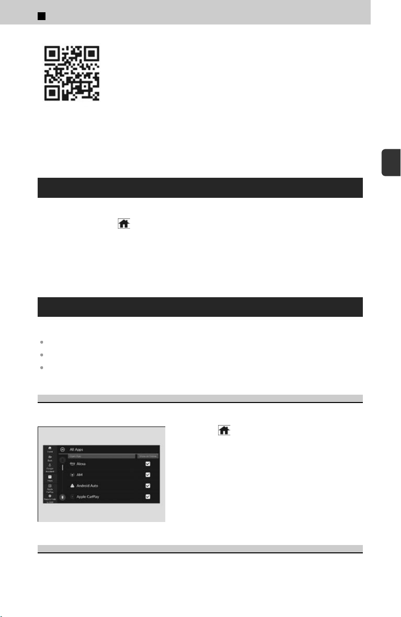
Additional information for Google apps and services is available at
m
ygarage.honda.com (U.S.) or www.honda.ca (English) / www.honda.ca/fr (French)
(Canada).
Reboot Audio
You can reboot the audio system.
[1] Select and hold
(Home) icon for a certain period of time.
[2] Select Reboot.
≫
If Safe Mode is selected, the audio system will be rebooted with third-party applications
turned off. After the power mode has been turned off once, third-party applications can
be used again.
Home Screen
App icons can be added, deleted, or moved on the home screen.
You cannot delete the All Apps icon.
Apps will not be deleted by deleting the icon on the home screen.
Select Tips to show tips. To hide them, select it again.
To Add/Remove App Icons on the Home Screen
App icons can be added or removed on the home screen.
[1] Select (Home) icon.
[2] Select All Apps.
[3] Select the apps you want to add or remove
and check/uncheck on the box.
To Move/Remove App Icons on the Home Screen
You can change where apps or delete apps are located on the home screen.
3
Controls > 12.3″ Color Touchscreen
209
3
Controls
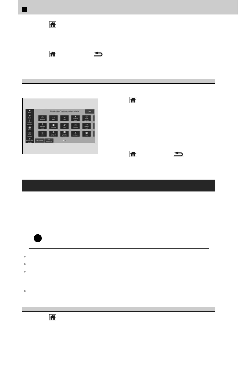
[1] Select (Home) icon.
[2] Select and hold an app icon.
[3] Drag and drop the app icon to where you want it to be.
≫
Drag and drop the icon you want to remove to the Hide icon.
[4] Select
(Home) icon or (Back) icon.
≫
The screen will return to the home screen.
To Store Shortcut Icons on the Home Screen
You can store up to three icons on the mode change switch bar.
[1] Select (Home) icon.
[2] Select and hold an app icon.
[3] Select Edit Shortcuts.
[4] Drag and drop the app icon you want to store
to the mode change switch bar.
≫
You can also store app icons in the mode
change switch bar by selecting icon ➔ shortcut
location.
[5] Select
(Home) icon or (Back) icon.
≫
The screen will return to the home screen.
System Updates
System Updates uses the telematics control unit (TCU) or Wi-Fi communication
capabilit
y to operate.
When an update for your system becomes available, a screen prompting you to
update your system will be displayed on the audio/information screen.
!
When a system update is started, the vehicle will be unable to move.
If new software has been released, perform an update as soon as possible.
If a system update fails, please consult a dealer.
System updates that change specifications may result in some discrepancies with the
information in this owner’s manual. For the most up-to-date information, please refer to the
Honda homepage.
Certain features may not be available during system updates.
Performing/Scheduling System Updates
[1] Select
(Home) icon.
[2] Select System Updates or Status bar ➔ system update message.
[3] Select Agree to Update to give permission for the update.
3
Controls > 12.3″ Color Touchscreen
210
[4] When the power mode is turned to OFF, the permission screen is displayed.
Once a system update is started, the vehicle will become unable to move.
≫
When you select Proceed Now, the system update begins immediately.
≫
If you select Set Update Time, you can set a time for the update to be performed.
≫
If you select Remind me Later, you can delay the system update. The permission
screen will be displayed again the next time the power mode is turned to OFF.
[5] The next time the power mode is turned to ON, the system update results screen
wil
l be displayed.
≫
System update results can also be viewed from Settings ➔ Update History within
System Updates.
!
For important updates, R
emind me Later will stop displaying after it
has been selected a certain number of times.
!
Make sure your vehicle is stopped in a safe location before starting a
s
ystem update.
!
If you have selected Agr
ee to Update on the agreement screen when
an update is being offered, or Automatic Update
*
is set to ON, and the
permission screen is not displayed even though the power mode is set
to OFF, it may be due to one or more of the conditions listed below. For
more information, consult a dealer.
The hood is open.
The shift position is not in P .
The vehicle is providing one or more emergency notifications.
The 12-volt battery is depleted.
!
If the system is being updated via Wi-Fi, you will not be able to use this
f
eature in some situations based on Wi-Fi authentication methods.
For example:
The connection requires you to log in.
Agreement to terms of use is required.
!
If you are disconnected from the network, the download will be
s
topped. Download is resumed when a new network connection is
established.
*: Not available on all models
3
Controls > 12.3″ Color Touchscreen
211
3
Controls
System Updates Settings
By selecting Set
tings and selecting a settings item, you can change or confirm the
system update settings.
The following settings items can be set.
Automatic Update
*
: You can change the automatic update.
Automatic Download: You can change the automatic download.
Control Unit Versions: You can confirm the version and update status.
Connection Setup: You can connect to the internet via a Wi-Fi network.
Wi-Fi Connection
u
P.222
Update History: You can confirm the update history.
!
To perform a system update via Wi-Fi, check the box next to your
desir
ed network in General Settings ➔ Connections ➔ Wi-Fi ➔
Options ➔ Add Network or Saved Networks.
Trip Computer
Displays the trip computer information.
Current Drive tab: Displays the current trip information.
Trip A/Trip B tab: Displays information for the current and three previous drives. The
information is stored every time you reset Trip A/B.
To reset the Trip A/B, select Menu, then select Delete Trip History.
To change the setting of how to reset Trip A/B, select Menu, then select “Trip A” Reset
Timing or “Trip B” Reset Timing.
Adjusting the Clock
You can adjust the time manually in the audio/information screen when the power
mode is in ON.
≫
The Guest user cannot adjust the clock.
Adjusting the Time
[1] Select
(Home) icon.
[2] Select General Settings.
[3] Select System.
[4] Select Date & Time.
[5] Select Set Date & Time.
[6] Select Automatic Date & Time, then select Off.
*: Not available on all models
3
Controls > 12.3″ Color Touchscreen
212
4
To adjust time
[7] Select Set Time.
[
8] Select / .
≫
AM/PM icon can be switched to each other either by selecting / , or by directly
touching the icon.
[9] Select the
(Back) icon to set the time.
4
To adjust date
[7] Select Set Dat
e.
[8] Select / .
[9] Select the (Back) icon to set the time.
You can also adjust the clock by selecting the clock image or time displayed on the B-
z
one.
[1] Select Dat
e & Time on the A-zone.
[2] Select Set Date & Time.
[3] Select Automatic Date & Time.
[4] Select Off.
[5] Select Set Date or Set Time.
[6] Select / to adjust the dates, hours, and minutes.
[7] Select the (Back) icon to set the date or time.
You can customize the clock display to show the 12 hour clock or 24 hour clock.
How to Customize the General Settings
u
P.239
You can customize the date display.
How to Customize the General Settings
u
P.239
The clock is automatically updated through the audio system.
Adjusting the Sound
[1] Select
(Home) icon.
[2] Select an audio app icon.
4
AM/FM Radio mode
[3] Select Menu ➔ Sound Set
tings.
[4] Select Sound Settings.
[5] Select the option you want to change.
4
USB Audio, Bluetooth Audio mode
[3] Select Sound.
[
4] Select the option you want to change.
3
Controls > 12.3″ Color Touchscreen
213
3
Controls

The following settings items can be set:
Bass / Mid / Treble: Treble, Midrange, Bass.
Bose Centerpoint
*1
: Turns Bose Centerpoint ON and OFF.
Audio Zones & Balance / Fader
*1
: Driver Only, Front Only, Rear Only, Full Vehicle, Balance,
Fader.
Bose Dynamic Speed Compensation
*1
: Sets the amount of volume increase.
Balance / Fader
*2
: Balance, Fader.
Speed Volume Compensation
*2
: Sets the amount of volume increase.
You can also adjust the sound by the following procedure.
[1] Select
(Home) icon.
[2] Select General Settings.
[3] Select Sound.
To reset each setting for Bas
s / Mid / Treble, Audio Zones & Balance / Fader
*1
,
Bose Dynamic Speed Compensation
*1
, Balance / Fader
*2
, and Speed Volume
Compensation
*2
, select Default on each setting screen.
*1: Models with BOSE AMP
*2: Models with Normal AMP
Changing the Screen Brightness
You can change the brightness of the audio/information screen.
[1] Select
(Home) icon.
[2] Select General Settings.
[3] Select Display.
[4] Select the setting you want.
≫
To reset the settings, select Reset to Default.
Alexa Built-In
You can talk to Amazon Alexa through the audio system. With Alexa, you can:
Stream music
Check the weather
Answer questions
Control smart home devices
And more with supported Alexa skills
Support Resources
For more information or client support:
Call Honda Customer Service at 1 (800) 999-1009.
Go to https://www.amazon.com/alexasupport.
3
Controls > 12.3″ Color Touchscreen
214
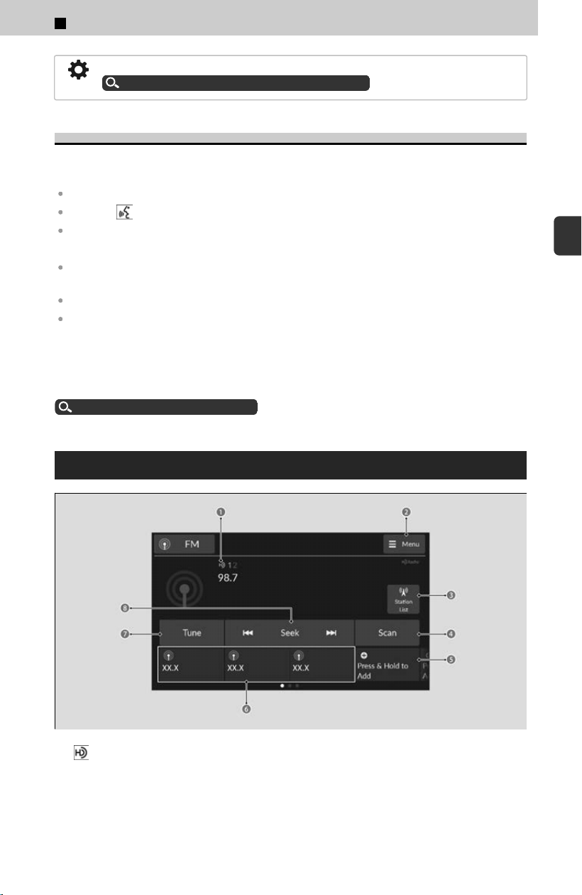
You can change the voice assistant from Alexa to Google Assistant.
How to Customize the General Settings
u
P.239
Using Alexa
Once you sign into Alexa in the vehicle, you can use Alexa without opening the app.
You can trigger Alexa by doing any of the following:
Say the wake word “Alexa” from anywhere in the audio system.
Press the (Talk) button on the steering wheel.
Select the Alexa icon from inside the app.
Troubleshooting Tips:
Make sure you are connected to Alexa via Wi-Fi network, AT&T Vehicle Data Plan, or
HondaLink.
If using an AT&T Vehicle Data Plan, confirm that your subscription is active.
Make sure you are logged into your Amazon account.
Deleting Your Alexa Settings from the Vehicle
For your privacy and security, if you transfer the vehicle to a third-party, reset all
v
ehicle settings to default and delete all personal data. Also, remove the vehicle from
the list of devices in your phone’s Alexa app.
Defaulting All the Settings
u
P.248
Playing AM/FM Radio
a Icon
b Menu Icon
c Station List Icon
d Scan Icon
e Press & Hold to Add Icon
3
Controls > 12.3″ Color Touchscreen
215
3
Controls

f Preset Icons
g Tune Icon
h Seek Icons
HD Subchannel
Displays the subchannel list when an HD Radio™ station is selected while listening to
an FM s
tation.
[1] Select S
tation List.
[2] Select the channel number.
AM/FM Settings
By selecting Menu ➔ HD R
adio ➔ settings item, you can change the AM/FM settings.
The following settings items can be set.
HD Radio: Automatically choose a digital or an analog channel, or listen to analog only.
Artwork: Turns the artwork display on and off.
Station List
Lists the strongest stations on the selected band.
[1] Select S
tation List to display a list.
[2] Select the station.
Manual update
Updates your available station list at any time.
[1] Select S
tation List to display a list.
[2] Select Refresh.
Radio Data System (RDS)
Provides text data information related to your selected RDS-capable FM station.
≫
When you select an RDS-capable FM station, the RDS automatically turns on, and the
frequency display changes to the station name. When the signals of that station become
weak, the display changes from the station name to the frequency.
To find an RDS station from station list
[1] Select Station List to display a list while listening to an FM station.
[2] Select the station.
Manual update
Updates your available station list at any time.
[1] Select S
tation List to display a list while listening to an FM station.
[2] Select Refresh.
3
Controls > 12.3″ Color Touchscreen
216
Scan Icon
Samples each of the strongest stations on the selected band for a few seconds. To
turn o
ff scan, select Stop or select (Back) icon.
Favorite Station
To switch the favorite station, select the preset icon.
≫
Swipe the preset icon area to display the next preset icons.
To add a station:
[1] Tune to the selected station.
[
2] Select and hold Press & Hold to Add.
≫
You can store 12 AM/FM stations into preset memory.
Editing a favorite station
Select and hold to desired favorite station icon.
The following items are available:
Remove Favorite: Delete the favorite station icon from the favorite station list.
Replace with (number): Replace the stored favorite station icon.
Add to Home: Add the shortcut icon of the stored favorite station to the home screen.
Tune Icon
Select to use of the on-screen keyboard for entering the radio frequency directly.
Seek Icons
Select
or to search the selected band up or down for a station with a
strong signal.
About Audio Playback
By connecting a device to the audio system, you can play audio files
.
!
It may be illegal to perform some data device functions while driving.
Available operating functions vary on models or versions. Some functions may not be
available on the vehicle’s audio system.
Depending on the connected device, in some cases, the name of the artist, album, or track
may not appear correctly.
3
Controls > 12.3″ Color Touchscreen
217
3
Controls
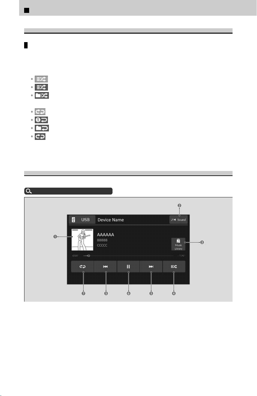
About Play Modes
Shuffle/Repeat
Repeatedly select the shuffle or repeat icon until you find a play mode op
tion of
your preference.
Shuffle
Shuffle off: Shuffle mode to off.
Shuffle all: Plays all available songs in random order.
Shuffle in folder
*1
: Plays all songs in the current folder in random order.
Repeat
Repeat off: Repeat mode to off.
Repeat song: Repeats the current song.
Repeat folder/group
*2
: Repeats all songs in the current folder/group.
Repeat all: Repeats all songs (in the current folder
*2
).
*1: When playing a song via USB device
*2: When playing a song using Bluet
ooth® Audio or via USB device
Audio Playback via Wired Connection
Connect a device, such as an iPod or iPhone, then select the USB ic
on.
About Wired Connections
u
P.205
a Cover Art
b Sound Icon
c Music Library Icon
d Shuffle Icon
e Track Icons
f Play/Pause Icon
g Repeat Icon
3
Controls > 12.3″ Color Touchscreen
218
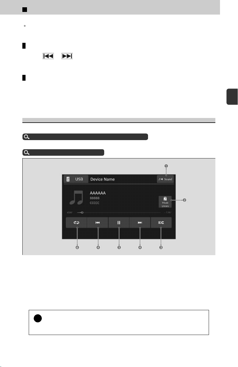
While an iPhone is connected via Apple CarPlay, audio files on the iPhone can only be played
using Apple CarPlay.
Track icons
Select
or to change songs.
Select and hold to move rapidly within a song.
How to select a song from the music search list
[1] Select Music Library.
[2] Select a search category (e.g., Artists, Albums, etc.).
[3] Continue making selections until you find the song of your choice.
Audio Playback via USB Device
The audio system can read certain USB drive formats to play audio files
.
Compatible iPod, iPhone, and USB Flash Drives
u
P.249
After connecting a USB device, select the USB ic
on.
About Wired Connections
u
P.205
a Sound Icon
b Music Library Icon
c Shuffle Icon
d Track Icons
e Play/Pause Icon
f Repeat Icon
!
WMA files pr
otected by digital rights management (DRM) cannot be
played.
3
Controls > 12.3″ Color Touchscreen
219
3
Controls
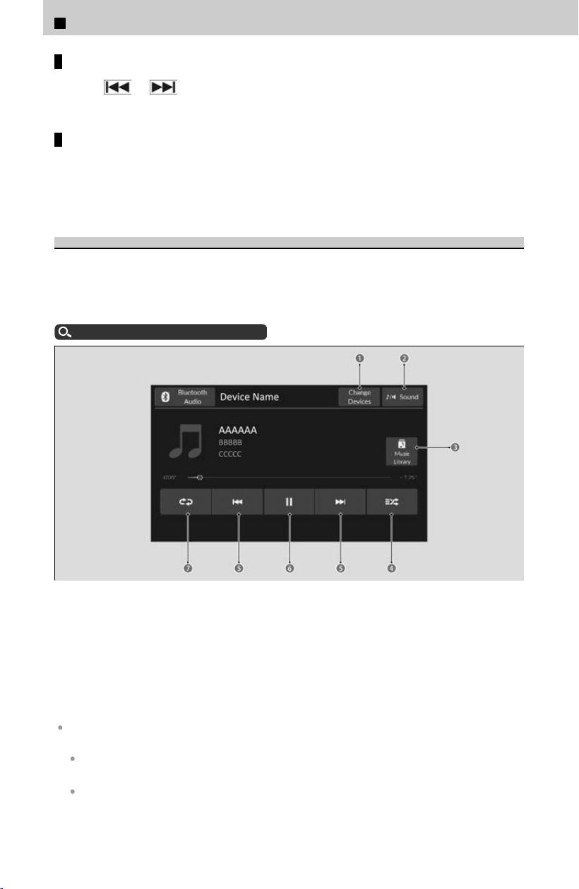
Track icons
Select
or to change songs.
Select and hold to move rapidly within a song.
How to select a song from the music search list
[1] Select Music Library.
[2] Select a search category (e.g., Artists, Albums, etc.).
[3] Continue making selections until you find the song of your choice.
Audio Playback via Bluetooth® Device
Your audio system allows you to listen to audio files fr
om your Bluetooth®-compatible
phone.
Connect a Bluetooth® compatible device to the system, then select the Bluetooth
Audio icon.
About Wireless Connections
u
P.205
a Change Devices Icon
b Sound Icon
c Music Library Icon
d Shuffle Icon
e Track Icons
f Play/Pause Icon
g Repeat Icon
Not all Bluetooth®-enabled phones with streaming audio capabilities are compatible with the
system. For a list of compatible phones:
U.S.: Visit https://mygarage.honda.com/s/honda-handsfreelink-compatibility-check, or call
1-888-528-7876.
Canada: Call 1-855-490-7351.
3
Controls > 12.3″ Color Touchscreen
220

Only one phone can be used with HFL at a time. When there is more than one paired phone in
the vehicle, the system automatically connects to the prioritized phone. You can assign
priority to a phone in the Bluetooth® device list.
About Wireless Connections
u
P.205
If more than one phone is paired to the HFL system, there may be a delay before the system
begins to play.
If a phone is currently connected via Apple CarPlay or Android Auto, Bluetooth® Audio from
that phone is unavailable.
To play the audio files, you may need to operate your phone. If so, follow the phone
manufacturer’s operating instructions.
Switching to another mode pauses the audio files playing from your phone.
You can change the connected phone by selecting Change Devices.
About Wireless Connections
u
P.205
Track icons
Select
or to change songs.
Select and hold to move rapidly within a song.
How to select a song from the music search list
[1] Select Music Library.
[2] Select a search category (e.g., Albums).
[3] Select an item.
≫
The selection begins playing.
HondaLink®
HondaLink® connects you to the latest information from Honda. You can connect your
phone wir
elessly through Wi-Fi or Bluetooth® and the HondaLink icon is selected, you
can operate HondaLink® on the audio/information screen.
Wi-Fi Connection
u
P.222
About Wireless Connections
u
P.205
If your vehicle has a telematics control unit (TCU), you can use HondaLink® without
connecting the phone.
The HondaLink® connect app is compatible with most iPhone and Android phones.
If the system is connected to the HondaLink® connect app through Bluetooth® and another
Bluetooth® audio device is connected, the Bluetooth® connection to the HondaLink® connect
app will be severed.
Some cell phone carriers charge for tethering and smartphone data use. Check your phone’s
data subscription package.
If there is an active connection to Apple CarPlay or Android Auto, HondaLink® can only be
connected through Wi-Fi.
3
Controls > 12.3″ Color Touchscreen
221
3
Controls

To Connect to HondaLink®
You can use the following procedure to connect to HondaLink®.
To enable the HondaLink® service
You must consent to location sharing to enable the HondaLink® service.
[1] Select
(Home) icon.
[2] Select General Settings.
[3] Select Privacy.
[4] Select Data Sharing with Honda.
[5] Select Enable.
To link with HondaLink®
You can see the connection guide screen after launching HondaLink® when there is
no c
onnection to a network. If you do not need this guide, select check-box and
select OK.
HondaLink® Menu
The following items can be use.
Vehicle Notifications: Displays instruction messages when the vehicle needs service.
Connect Honda: Displays tips for vehicle usage, and gets support via roadside or customer
service center.
Connect: Displays your phone connection status and HondaLink® subscription status.
HondaLink® Service
Is a subscription-based service that provides convenient features such as voice
c
ommunication in case of emergency, online security, and one-on-one operator
assistance.
HondaLink® also provides services you can operate from the Internet or your
smartphone.
To subscribe to HondaLink®, or to get more information about all of its features,
contact a Honda dealer, or visit https://mygarage.honda.com/s/hondalink-marketing
(U.S.) or https://www.honda.ca/en/hondalink (English) / https://www.honda.ca/fr/
hondalink (French) (Canada).
Wi-Fi Connection
This vehicle is equipped with Wi-Fi connectivity. You can connect to a communication
de
vice. In addition, the vehicle can be used by other communication devices as a Wi-
Fi hotspot via the telematics control unit (TCU).
Use Wi-Fi Inside the Vehicle
3
Controls > 12.3″ Color Touchscreen
222

Connect to the In-vehicle Wi-Fi Hotspot
Wi-Fi and Wi-Fi Direct are registered trademarks of Wi-Fi Alliance®.
Use Wi-Fi Inside the Vehicle
[1] Select
(Home) icon.
[2] Select General Settings.
[3] Select Connections.
[4] Select Wi-Fi.
≫
To change the Wi-Fi settings, select Options.
[5] Select the access point you want to connect to the system.
[
6] Select Connect.
≫
When the connection is successful, the status text Connected next to the network name
is displayed on the list.
[7] Select
(Home) icon to go back to the home screen.
You cannot go through the setting procedure while the vehicle is moving. Park in a safe place
to set the audio system in Wi-Fi mode.
Some cell phone carriers charge for tethering and smartphone data use. Check your phone’s
data subscription package.
Check your phone manual to find out if the phone has Wi-Fi connectivity.
You can confirm whether Wi-Fi connection is on or off with the icon on the Wi-Fi network
list. Transmission speed and others will not be displayed on this screen.
In case of Wi-Fi connection with your phone, make sure your phone’s Wi-Fi setting is in access
point (tethering) mode.
When you select Access Point, you can set up a wireless connection from the phone to the
vehicle.
How to Customize the General Settings
u
P.239
Connect to the In-vehicle Wi-Fi Hotspot
You can set the network as a Wi-Fi hotspot of this audio system. Use the following
s
teps to set up.
[1] Select
(Home) icon.
[2] Select General Settings.
[3] Select Connections.
[4] Select Data Connection Options.
[5] Select Set Up Wi-Fi.
[6] Select Options.
[7] Select Add Network.
[8] Select Connect.
The following options are available for the setup.
Network SSID: Set this network name.
3
Controls > 12.3″ Color Touchscreen
223
3
Controls
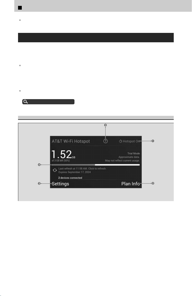
Security: Set a password to be required when connecting a Wi-Fi device to this network.
AT&T Hotspot
If you have subscribed to AT&T hotspot services, your vehicle will provide data to
c
onnect your mobile devices to the Internet. You can use the AT&T Hotspot app to
turn vehicle data on/off and monitor data usage left on your subscription.
To use AT&T Hotspot services, your vehicle must be subscribed to a data plan. If your vehicle
is not subscribed to a data plan, you can add vehicle data services at:
U.S.: www.att.com/honda
Canada: https://myvehicle.att.com/#/honda/learn?country=CA&language=en (English)
https://myvehicle.att.com/#/honda/learn?country=CA&language=fr (French)
Alternatively, you can use your mobile hotspot to connect the vehicle and other mobile
devices to the Internet.
Wi-Fi Connection
u
P.222
AT&T Hotspot Menu
a Hotspot Enable
Turn AT&T Hotspot on/off.
b Plan Info
Shows your current AT&T subscription plan for the vehicle.
c Settings
Shows the current username and password for vehicle Hotspot. Settings can be
changed while the vehicle is not in motion.
d Data Usage Bar
3
Controls > 12.3″ Color Touchscreen
224
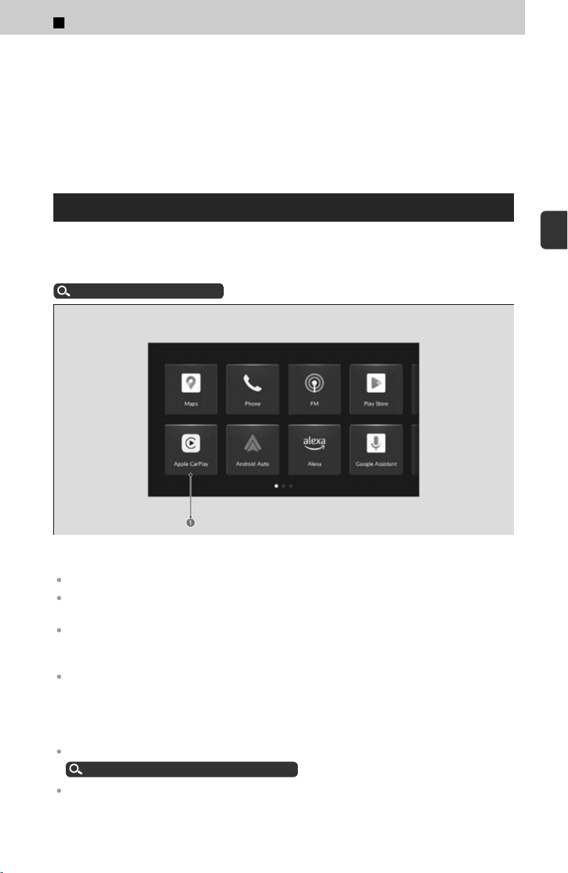
Check the current status of your data plan. This Usage Bar will show your current plan
and how much data remains on your plan. Subscription plans for AT&T Hotspot can
be added/modified at:
U.S.: www.att.com/honda
Canada: https://myvehicle.att.com/#/login
e Help
Apple CarPlay
If you connect an Apple CarPlay-compatible iPhone to the system, via USB port or
wir
elessly, and the Apple CarPlay icon is selected, you can operate Apple CarPlay on
the audio/information screen.
Connecting a Device
u
P.204
a Apple CarPlay Icon
Only iPhone 5s or newer versions with iOS 11.3 or later are compatible with Apple CarPlay.
Park in a safe place before connecting your iPhone to Apple CarPlay and when launching any
compatible apps.
You can also use the method below to set up Apple CarPlay:
Select Home ➔ General Settings ➔ Connections ➔ Manage Device Connections ➔ Select
Device.
While connected to Apple CarPlay, it is not possible to use the Bluetooth® Audio or Bluetooth®
HandsFreeLink®. Calls and audio playback will be handled exclusively through Apple CarPlay.
If you want to make a call with Bluetooth® HandsFreeLink®, turn Apple CarPlay OFF or detach
the USB cable from your iPhone. Other previously paired phones can also use the Bluetooth®
Audio.
When using Hands Free, you can only control it with Siri.
Operating Apple CarPlay with Siri
u
P.227
Apple CarPlay and Android Auto cannot run at the same time.
3
Controls > 12.3″ Color Touchscreen
225
3
Controls

For details on countries and regions where Apple CarPlay is available, as well as information
pertaining to function, refer to the Apple homepage.
Apple CarPlay Operating Requirements & Limitations
Apple CarPlay requires a compatible iPhone with an active cellular connection and data plan.
Your carrier’s rate plans will apply.
Changes in operating systems, hardware, software, and other technology integral to providing
Apple CarPlay functionality, as well as new or revised governmental regulations, may result in
a decrease or cessation of Apple CarPlay functionality and services. Honda cannot and does
not provide any warranty or guarantee of future Apple CarPlay performance or functionality.
It is possible to use third-party apps if they are compatible with Apple CarPlay. Refer to the
Apple homepage for information on compatible apps.
Use of Apple CarPlay will result in the collection of certain user and vehicle information (such
as vehicle location, speed, and status) from your iPhone to enhance the Apple CarPlay
experience. You will need to consent to the sharing of this information on the audio/
information screen.
Use of user and vehicle information
The use and handling of user and vehicle information transmitted to/from your iPhone by
Apple CarPlay is governed by the Apple iOS terms and conditions and Apple’s Privacy Policy.
Wireless Apple CarPlay and AT&T Hotspot cannot be used at the same time. When using
Apple CarPlay and AT&T Hotspot at the same time, connect to Apple CarPlay with a USB
cable.
If there is a problem with the connection of your iPhone, an error code will be displayed.
How to Customize the General Settings
u
P.239
Apple CarPlay Menu
For details on available applications, please refer to the Apple CarPlay homepage.
Apps displayed on your screen can be changed with your iPhone.
Select the Honda ic
on on the Apple CarPlay menu screen to go back to the home
screen.
Connecting Apple CarPlay Using the USB Cable
Connect the iPhone to the USB port.
About Wired Connections
u
P.205
If another phone is already connected to the audio system, the c
onfirmation screen
will appear, and then select Continue Connecting.
Connecting Apple CarPlay Wirelessly
Connecting Apple CarPlay wirelessly on the home screen
[1] Select
(Home) icon.
[2] Select Apple CarPlay.
[3] Select Check Device List or Connect New Phone.
[4] Pair the iPhone to the vehicle’s Bluetooth® HandsFreeLink® (HFL) system.
About Wireless Connections
u
P.205
3
Controls > 12.3″ Color Touchscreen
226
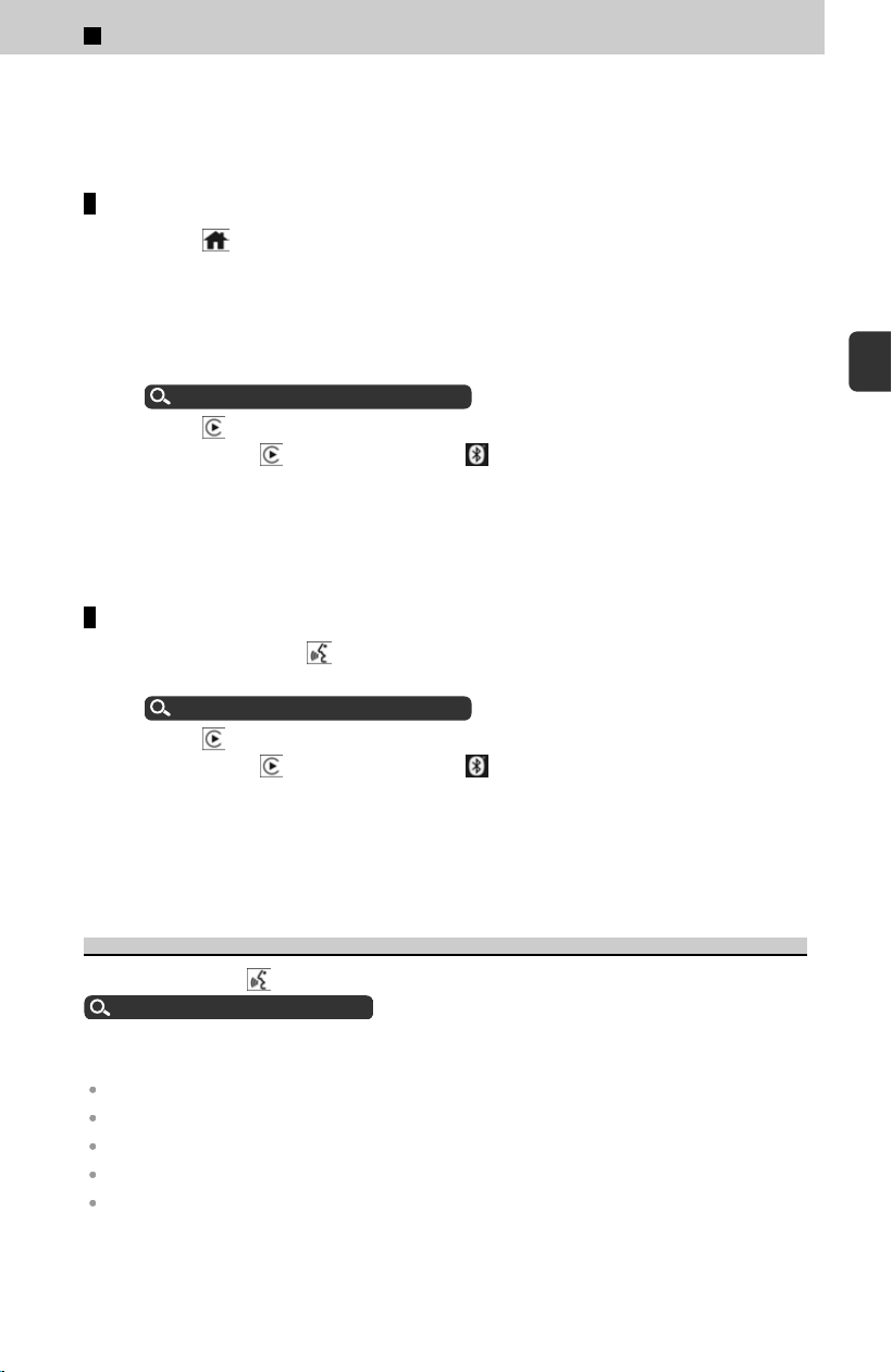
[5] Select Yes.
≫
If your iPhone asks for permission to accept an Apple CarPlay connection, accept to
connect.
Connect Apple CarPlay wirelessly on the Bluetooth® device list
[1] Select
(Home) icon.
[2] Select General Settings.
[3] Select Connections.
[4] Select Manage Device Connections.
[5] Select + Connect New Device.
[6] Pair the iPhone to the vehicle’s Bluetooth® HandsFreeLink® (HFL) system.
About Wireless Connections
u
P.205
[7] Select
icon.
≫
If you select icon, you cannot select icon.
[8] Select Connect.
[
9] Select Yes.
≫
If your iPhone asks for permission to accept an Apple CarPlay connection, accept to
connect.
Connect Apple CarPlay wirelessly with the steering wheel
[1] Press and hold the
(Talk) button on the steering wheel.
[2] Pair the iPhone to the vehicle’s Bluetooth® HandsFreeLink® (HFL) system.
About Wireless Connections
u
P.205
[3] Select
icon.
≫
If you select icon, you cannot select icon.
[4] Select Connect.
[
5] Select Yes.
≫
If your iPhone asks for permission to accept an Apple CarPlay connection, accept to
connect.
Operating Apple CarPlay with Siri
Press and hold the
(Talk) button to activate Siri. Press again to deactivate Siri.
Audio Remote Controls
u
P.203
Press and release to activate standard voice recognition system.
Below are examples of questions and commands for Siri:
What movies are playing today?
Call dad at work.
What song is this?
How’s the weather tomorrow?
Read my latest email.
For more information, please visit w
ww.apple.com/ios/siri.
3
Controls > 12.3″ Color Touchscreen
227
3
Controls
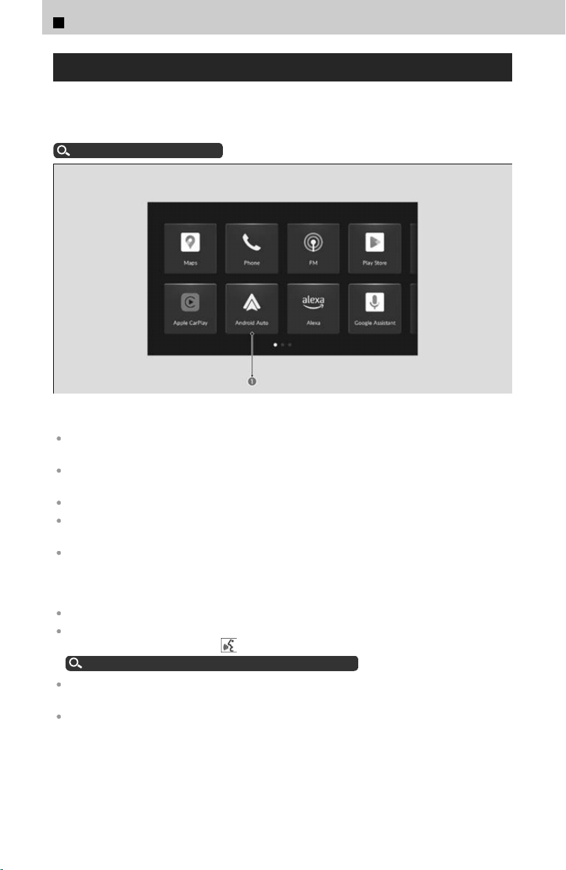
Android Auto™
If you connect an Android™ phone to the system, via USB port or wirelessly, and the
Andr
oid Auto icon is selected, you can operate Android Auto on the audio/
information screen.
Connecting a Device
u
P.204
a Android Auto Icon
We recommend that you update Android OS to the latest version when using Android Auto.
Bluetooth® A2DP cannot be used while your phone is connected to Android Auto.
To use Android Auto on a smartphone with Android 9.0 (Pie) or earlier, you need to download
the Android Auto app from Google Play to your smartphone.
Android and Android Auto are trademarks of Google LLC.
Park in a safe place before connecting your Android phone to Android Auto and when
launching any compatible apps.
You can use the method below to change Android Auto settings after you have completed the
initial setup:
Select Home ➔ General Settings ➔ Connections ➔ Manage Device Connections ➔ Select
Device.
Apple CarPlay and Android Auto cannot run at the same time.
To use each of Android Auto’s features: say a wakeup word while the Android Auto screen is
displayed, or press and hold the
(Talk) button to activate Google Assistant.
Operating Android Auto with Google Assistant
u
P.230
For details on countries and regions where Android Auto is available, as well as information
pertaining to function, refer to the Android Auto homepage.
Android Auto Operating Requirements & Limitations
Android Auto requires a compatible Android phone with an active cellular connection and
data plan. Your carrier’s rate plans will apply.
Changes in operating systems, hardware, software, and other technology integral to providing
Android Auto functionality, as well as new or revised governmental regulations, may result in a
decrease or cessation of Android Auto functionality and services. Honda cannot and does not
provide any warranty or guarantee of future Android Auto performance or functionality.
3
Controls > 12.3″ Color Touchscreen
228

It is possible to use third-party apps if they are compatible with Android Auto. Refer to the
Android Auto homepage for information on compatible apps.
Use of user and vehicle information
The use and handling of user and vehicle information transmitted to/from your phone by
Android Auto is governed by Google’s Privacy Policy.
Wireless Android Auto and AT&T Hotspot cannot be used at the same time. When using
Android Auto and AT&T Hotspot at the same time, connect to Android Auto with a USB cable.
If there is a problem with the connection of your smartphone, an error code will be displayed.
How to Customize the General Settings
u
P.239
Android Auto Menu
For details on available applications, please refer to the Android Auto homepage.
Apps displayed on your screen can be changed with your smartphone.
Select the Honda ic
on on the Android Auto menu screen to go back to the home
screen.
Connecting Android Auto Using the USB Cable
Connect the Android phone to the USB port.
About Wired Connections
u
P.205
If another phone is already connected to the audio system, the c
onfirmation screen
will appear, and then select Continue Connecting.
Connecting Android Auto Wirelessly
Connecting Android Auto wirelessly on the home screen
[1] Select
(Home) icon.
[2] Select Android Auto.
[3] Select Check Device List or Connect New Phone.
[4] Pair the Android phone to the vehicle’s Bluetooth® HandsFreeLink® (HFL)
system.
About Wireless Connections
u
P.205
[5] Select Y
es.
≫
If your Android phone asks for permission to accept an Android Auto connection,
accept to connect.
Connect Android Auto wirelessly on the Bluetooth® device list
[1] Select
(Home) icon.
[2] Select General Settings.
[3] Select Connections.
[4] Select Manage Device Connections.
[5] Select + Connect New Device.
3
Controls > 12.3″ Color Touchscreen
229
3
Controls
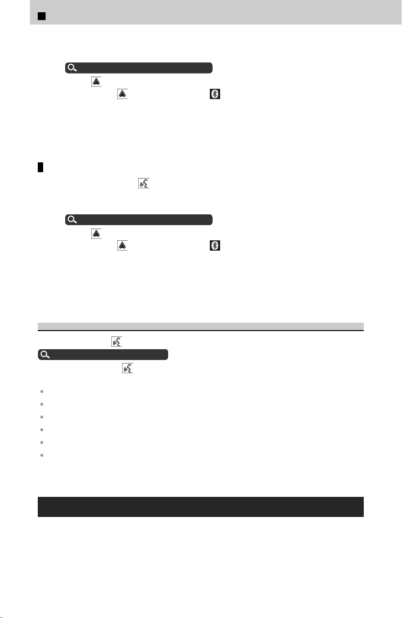
[6] Pair the Android phone to the vehicle’s Bluetooth® HandsFreeLink® (HFL)
system.
About Wireless Connections
u
P.205
[7] Select
icon.
≫
If you select icon, you cannot select icon.
[8] Select Connect.
[
9] Select Yes.
≫
If your Android phone asks for permission to accept an Android Auto connection,
accept to connect.
Connect Android Auto wirelessly with the steering wheel
[1] Press and hold the
(Talk) button on the steering wheel.
[2] Pair the Android phone to the vehicle’s Bluetooth® HandsFreeLink® (HFL)
system.
About Wireless Connections
u
P.205
[3] Select
icon.
≫
If you select icon, you cannot select icon.
[4] Select Connect.
[
5] Select Yes.
≫
If your Android phone asks for permission to accept an Android Auto connection,
accept to connect.
Operating Android Auto with Google Assistant
Press and hold the
(Talk) button to talk to Google Assistant.
Audio Remote Controls
u
P.203
Press and release the
(Talk) button to activate the Google Assistant.
Below are examples of commands you can give with Google Assistant:
Reply to text.
Call my wife.
Navigate to Honda.
Play my music.
Send a text message to my wife.
Call flower shop.
For more information, please refer to the Android Auto homepage.
Google built-in
You can use the features available with Google built-in on the audio/information
scr
een.
3
Controls > 12.3″ Color Touchscreen
230
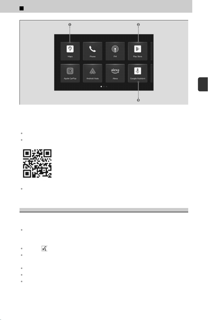
a Google Maps
b Google Play
c Google Assistant
Google, Google Play, and Google Maps are trademarks of Google LLC.
For more details on Google Apps and Services’ features, visit the Google homepage.
Additional information for Google Apps and Services is available at US: mygarage.honda.com
or Canada: www.honda.ca (English), www.honda.ca/fr (French).
Google Assistant
You can operate features with hands-free help from Google Assistant.
You can activate Google Assistant by:
Saying “Hey Google”.
≫
Wake words vary by region and language. Refer to the Google homepage for more
information.
Press the (Talk) button on the steering wheel.
Selects the Google Assistant icon on the audio/information screen.
Below are examples of things you can ask Google Assistant:
Turn on the seat heater.
Play music.
Play radio.
3
Controls > 12.3″ Color Touchscreen
231
3
Controls
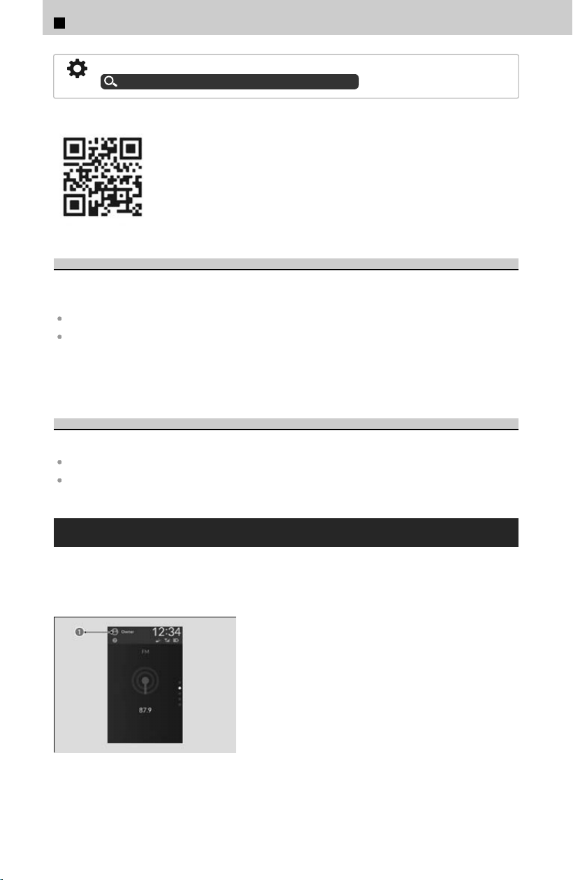
You can customize language and other settings regarding Google Assistant.
How to Customize the General Setting
u
P.239
Refer to the Google homepage for more information.
Google Maps
Google Maps helps you reach your next destination faster with real-time tr
affic info,
automatic rerouting, and voice control.
Operate when vehicle is stopped in a safe location.
When your Google Account is linked with a valid user, destinations stored on other devices
(home, work, favorites, previous searches, etc.) can be displayed. When the device and the
vehicle are logged into the same Google Account, changing information on the device will
change it on Google Maps as well.
Google Play
Download your favorite apps on Google Play.
The vehicle must be stopped in order to download an app.
Operate when vehicle is stopped in a safe location.
User Information
You can add and change users, as well as customize user settings. By registering a
user
, you can personalize your vehicle settings. You can select a user when the audio/
information screen loads, even when the doors are open or unlocked.
a User Information
3
Controls > 12.3″ Color Touchscreen
232
By linking your profile with your Google Account, you can enjoy a more personalized
experience with Google built-in. For more assistance on account linking, visit the
Google homepage.
You can customize settings individually for each user.
How to Customize the Profile Settings
u
P.247
You can customize security settings for each user. If you have forgotten security settings, you
will need to delete the user and create a new one. If you have forgotten security settings for
the Owner user, please contact a dealer or Honda Customer Service.
Contacts
u
P.427
Certain features are unavailable when using a newly created user or the Guest user.
Registering a User
[1] Select User Information.
≫
You can also add users when Profile Settings ➔ Change Profile is selected.
How to Customize the Profile Settings
u
P.247
≫
You can add users even when the doors are open and unlocked.
[2] Select Chang
e Profile.
[3] Select +Add User.
[4] Select OK.
[5] Enter User Information.
Start Up
u
P.208
You can add up to 4 users other than the Owner user and the Guest user.
When you add a user, the audio/information screen is loaded under that user.
Switching Users
[1] Select User Information.
≫
You can also change users when Profile Settings ➔ Change Profile is selected.
How to Customize the Profile Settings
u
P.247
≫
You can switch users even when the doors are open and unlocked.
[2] Select Chang
e Profile.
[3] Select the user you want to use.
Users with customized security settings can restrict screen operations by selecting the
Screen Lock shortcut.
3
Controls > 12.3″ Color Touchscreen
233
3
Controls
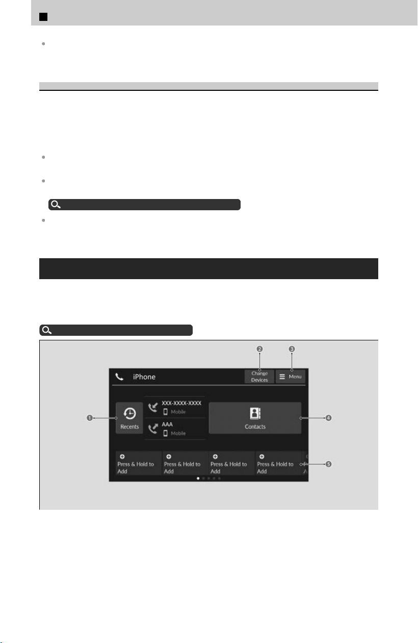
The transmitter settings may not be switched when you change the Owner user. If this
happens, change to a different user and then try switching to the desired user again.
Deleting Users
[1] Select P
rofile Settings.
[2] Select Manage Profile.
[3] Select Profiles & accounts.
[4] Select Delete your profile.
When the profile currently being used is deleted, the audio/information screen is loaded
under the Guest user.
While using the Owner user, you can delete other users via General Settings ➔ Advanced
Settings.
How to Customize the General Settings
u
P.239
Depending on the version of your OS, the steps for deleting a user may differ from the
instructions on this page. Follow the on-screen prompts.
Bluetooth® HandsFreeLink®
Bluetooth® HandsF
reeLink® (HFL) allows you to place and receive phone calls using
your vehicle’s audio system without handling your cell phone. Select the Phone icon
when your phone is connected to the system wirelessly.
About Wireless Connections
u
P.205
a Recents Icon
b Change Devices Icon
c Menu Icon
d Contacts Icon
e Favorite Contacts Icons
3
Controls > 12.3″ Color Touchscreen
234
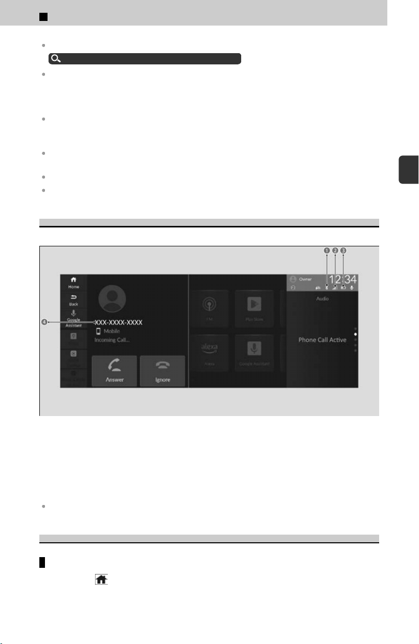
To use the system, the Bluetooth setting must be On.
How to Customize the General Settings
u
P.239
Bluetooth® Wireless Technology
The Bluetooth® word mark and logos are registered trademarks owned by Bluetooth SIG, Inc.,
and any use of such marks by Honda Motor Co., Ltd., is under license. Other trademarks and
trade names are those of their respective owners.
HFL Limitations
An incoming call on HFL will interrupt the audio system when it is playing. It will resume when
the call is ended.
When you select a name from the list in the cellular phonebook, you can see a category icon.
The icons indicate what types of numbers are stored for that name.
On some phones, it may not be possible to import the category icons to the system.
Depending on the connected cell phone, some features may not be available.
HFL Status Display
The audio/information screen notifies y
ou when there is an incoming call.
a Bluetooth® Indicator
Appears when your phone is connected to HFL.
b Signal Strength
c Battery Level Status
d Name saved in contacts/Caller’s Number (if not registered)
The information that appears on the audio/information screen varies between phone models.
Favorite Contacts
To add a favorite contact
[1] Select
(Home) icon.
[2] Select Phone.
3
Controls > 12.3″ Color Touchscreen
235
3
Controls

[3] Select and hold Press & Hold to Add.
[4] Select From Recents, From Contacts, or Using Enter Number.
4
From Recents, From Contacts
[5] Select a phone number.
4
Using Enter Number
[5] Input number, and select Ent
er.
To edit a favorite contact
[1] Select
(Home) icon.
[2] Select Phone.
[3] Select and hold a favorite contact.
[4] Select Edit Favorites.
≫
To delete a favorite contact, select Remove Favorite.
[5] Select a setting you want.
[
6] Select Enter or select type.
Add a favorite contact to homepage
[1] Select
(Home) icon.
[2] Select Phone.
[3] Select and hold a favorite contact.
[4] Select Add to Home.
Making a Call
You can make calls by inputting any phone number, or by using the imported recent
cal
ls, favorite contacts, and contacts entries.
To make a call using the imported phonebook
[1] Select
(Home) icon.
[2] Select Phone.
[3] Select Contacts.
[4] Select a name.
≫
You can sort by First Name or Last Name. Select the icon on the upper right of the
screen.
[5] Select a number.
≫
Dialing starts automatically.
To make a call using a phone number
[1] Select
(Home) icon.
[2] Select Phone.
[3] Select Menu.
3
Controls > 12.3″ Color Touchscreen
236
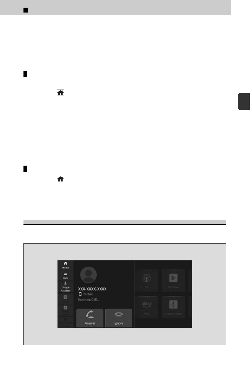
[4] Select Keypad.
[5] Select a number.
≫
Use the keyboard on the touch screen for entering numbers.
[6] Select Cal
l.
≫
Dialing starts automatically.
To make a call using the call history
Call history is stored by Al
l, Dialed, Missed, and Received.
[1] Select
(Home) icon.
[2] Select Phone.
[3] Select Recents.
≫
You can sort by All, Dialed, Missed, or Received. Select the icon on the upper right of
the screen.
[4] Select a number or contact name.
≫
Dialing starts automatically.
The call history appears only when a phone is connected to the system.
To make a call using a favorite contacts entry
[1] Select
(Home) icon.
[2] Select Phone.
[3] Select a desired favorite contact.
≫
Dialing starts automatically.
Receiving a Call
When there is an incoming call, an audible notification sounds (if activ
ated) and the
Incoming Call… screen appears.
3
Controls > 12.3″ Color Touchscreen
237
3
Controls
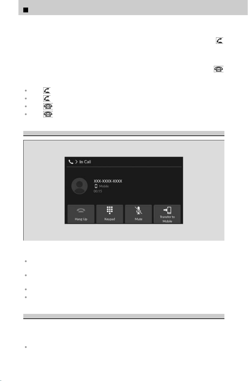
To answer the call:
Select the Answer icon.
You can also answer the call using the left selector wheel roll up or down to select
(Answer) on the driver information interface.
To decline or end the call:
Select the Ignore icon.
You can also ignore the call using the left selector wheel roll up or down to select
(Ignore) on the driver information interface.
Call Waiting:
Select (Answer) to put the current call on hold to answer the incoming call.
Select using the left selector wheel to return to the current call.
Select (Ignore) to ignore the incoming call if you do not want to answer it.
Select if you want to hang up the current call.
Options During a Call
The following options are available during a call.
Hang Up: End the call. Calls can also be ended from the Driver Information Interface by
moving the left selector wheel up and down.
Keypad: Send numbers during a call. This is useful when you call a menu-driven phone
system.
Mute: Mute your voice.
Transfer to Mobile: Transfer a call from the system to your phone.
Phone Menu Screen
By selecting Menu and select a set
tings item, you can change the Bluetooth®
HandsFreeLink® settings.
The following settings items can be set.
Keypad: Enter a phone number to dial.
3
Controls > 12.3″ Color Touchscreen
238
Latest Call History: Set whether the history shortcut is displayed in the phone screen.
Auto Sync Phone: Set phonebook and call history data to be automatically imported when a
phone is paired to HFL.
Auto Phone Call Transfer: Set calls to automatically transfer from your phone to HFL when
you enter the vehicle.
Ringtone: Select a fixed ringtone or the one from the connected cell phone.
Customized Features
Use the audio/information screen to customize certain features.
!
When you customize settings:
Make sure that the vehicle is at a complete stop.
Put the transmission into P .
How to Customize the General Settings
With the power mode in ON, select
(Home) icon ➔ General Settings ➔ setting
item.
List of Customizable Options
System
Date & Time ➔ Set Date & Time
Automatic Date & Time
On
*1
/Off
Set Date
Adjusts date.
Adjusting the Clock
u
P.212
Set Time
Adjusts clock.
Adjusting the Clock
u
P.212
Date & Time ➔ Time Zone
Automatic Time Zone
On
*1
/Off
(Select time zone)
Changes the time zone manually.
Date & Time ➔ Auto Daylight
Saving Time
On
*1
/Off
Date & Time ➔ Date Format
Day-of-week, MM DD, YYYY
*1
/
YYYY.MM.DD Day-of-week/
YYYY.MM.DD (Day-of-week)/Day-of-
week DD.MM.YYYY/DD.MM.YYYY
Date & Time ➔ Time Format
12H
*1
/24H
3
Controls > 12.3″ Color Touchscreen
239
3
Controls
Language
English (United States)
*1
/Español/
Français
Touch Panel Sensitivity
Low
*1
/High
About ➔ IP Address
Displays the Android setting items.
About ➔ Wi-Fi MAC Address
Displays the Android setting items.
About ➔ Bluetooth MAC Address
Displays the Android setting items.
About ➔ Serial Number
Displays the Android setting items.
About ➔ Up Time
Displays the Android setting items.
About ➔ Model Number
Displays the Android setting items.
About ➔ Android Version
Displays the Android setting items.
About ➔ Kernel Version
Displays the Android setting items.
About ➔ Build Number
Displays the Android setting items.
About ➔ Software Version
Displays the Android setting items.
Factory Data Reset
Cancel/Continue
*1: Default Setting.
Connections
Manage Device Connections ➔
Options
Bluetooth
On
*1
/Off
Priority Device Information
Displays the priority device.
Change Name
Changes vehicle name for Bluetooth®
connection setting.
Smartphone Projection Screen Size
Normal/Wide
*1
Smartphone Projection Error Code
Displays the error codes of the
smartphone projection.
Manage Device Connections ➔ +
Connect New Device
Pairs a new phone to HFL.
About Wireless Connections
u
P.205
Manage Device Connections ➔
(Saved Devices)
Connects, disconnects, or deletes a
paired phone.
About Wireless Connections
u
P.205
Wi-Fi ➔ Options
Wi-Fi
On
*1
/Off
3
Controls > 12.3″ Color Touchscreen
240
Add Network
Allows you to connect to a new external
network.
Saved Networks
Delete a saved network or change
update permission settings for the
selected network.
Wi-Fi ➔ (Detected Networks)
Displays the detected network(s).
Access Point ➔ Options
Access Point
On/Off
*1
Edit Access Point Settings
This screen allows you to change the
security settings and password.
Data Connection Options ➔ Set
Up Wi-Fi
Sets personal hotspot (phone
tethering).
Wi-Fi Connection
u
P.222
Data Connection Options ➔ Set
Up Vehicle Data Plan
Sets AT&T vehicle data plan.
AT&T Hotspot
u
P.224
*1: Default Setting.
Privacy
Data Sharing with Honda
Disable/Enable
*1
Microphone
Use microphone
On
*1
/Off
Recently accessed
Displays recent apps that accessed the
microphone.
Manage microphone permissions
Displays the microphone permissions.
Location
Sets the data sharing permission for
each function.
App permissions
Sets the data sharing permission for
each function.
System-wide Permission Settings
Sets the data sharing permission for
each function.
Infotainment system data
Sets the data sharing permission for
each function.
Data sharing with Google
*2
Sets the data sharing permission for
each function.
Ads
Sets the data sharing permission for
each function.
Google legal
*2
➔ Google Terms of
Service
*2
Displays the Google URL.
Google legal
*2
➔ Google Privacy
Policy
*2
Displays the Google URL.
3
Controls > 12.3″ Color Touchscreen
241
3
Controls
*1: Default Setting.
*2: Please confirm the details on the audio/
information screen. Specifications are
subject to change via system updates,
etc.
Display
Brightness
Changes the brightness of the audio/
information screen.
Contrast
Changes the contrast of the audio/
information screen.
Black Level
Changes the black level of the audio/
information screen.
Day Mode
*1
Changes to the daytime mode.
Night Mode
*1
Changes to the night mode.
Display Off
Turns the audio/information screen
brightness off.
*1: When the AID sensor is disabled.
Sound
Bass / Mid / Treble
Treble
Adjusts the settings of the audio
speakers’ sound.
Adjusting the Sound
u
P.213
Midrange
Adjusts the settings of the audio
speakers’ sound.
Adjusting the Sound
u
P.213
Bass
Adjusts the settings of the audio
speakers’ sound.
Adjusting the Sound
u
P.213
Bose Centerpoint
*
Adjusts the settings of the audio
speakers’ sound.
Adjusting the Sound
u
P.213
Audio Zones & Balance / Fader
*
Adjusts the settings of the audio
speakers’ sound.
Adjusting the Sound
u
P.213
Bose Dynamic Speed
Compensation
*
Adjusts the settings of the audio
speakers’ sound.
Adjusting the Sound
u
P.213
Balance / Fader
*
Adjusts the settings of the audio
speakers’ sound.
Adjusting the Sound
u
P.213
Speed Volume Compensation
*
Adjusts the settings of the audio
speakers’ sound.
Adjusting the Sound
u
P.213
*: Not available on all models
3
Controls > 12.3″ Color Touchscreen
242

Sound Volume
System Sounds
0~2
*1
~3
Voice Recognition
1~2
*1
~11
Navigation Guidance
0~6
*1
~11
Phone Calls
0~20
*1
~40
*1: Default Setting.
Camera
Rear Wide Camera
*
➔ Guidelines
Fixed Guideline
On
*1
/Off
Dynamic Guideline
On
*1
/Off
Multi View Camera
*
➔ Guidelines
Fixed Guideline
On
*1
/Off
Dynamic Guideline
On
*1
/Off
Multi View Camera
*
➔ Customize
Show after Shifting from Reverse
On/Off
*1
Auto Display When Obstacle is
Detected
On
*1
/Off
Cross Traffic Monitor
On
*1
/Off
*1: Default Setting.
Voice Control
Default Assist App
None/Alexa/Google Assistant
*1
Listen for “Hey Siri”
*2
On/Off
*3
Google Assistant
Sets the functions of Google Assistant.
*1: Default Setting.
*2: Activ
ates when the iPhone is connected.
*3: Default Setting (when Apple CarPlay is
launched, the setting will be switched to
On).
*: Not available on all models
3
Controls > 12.3″ Color Touchscreen
243
3
Controls
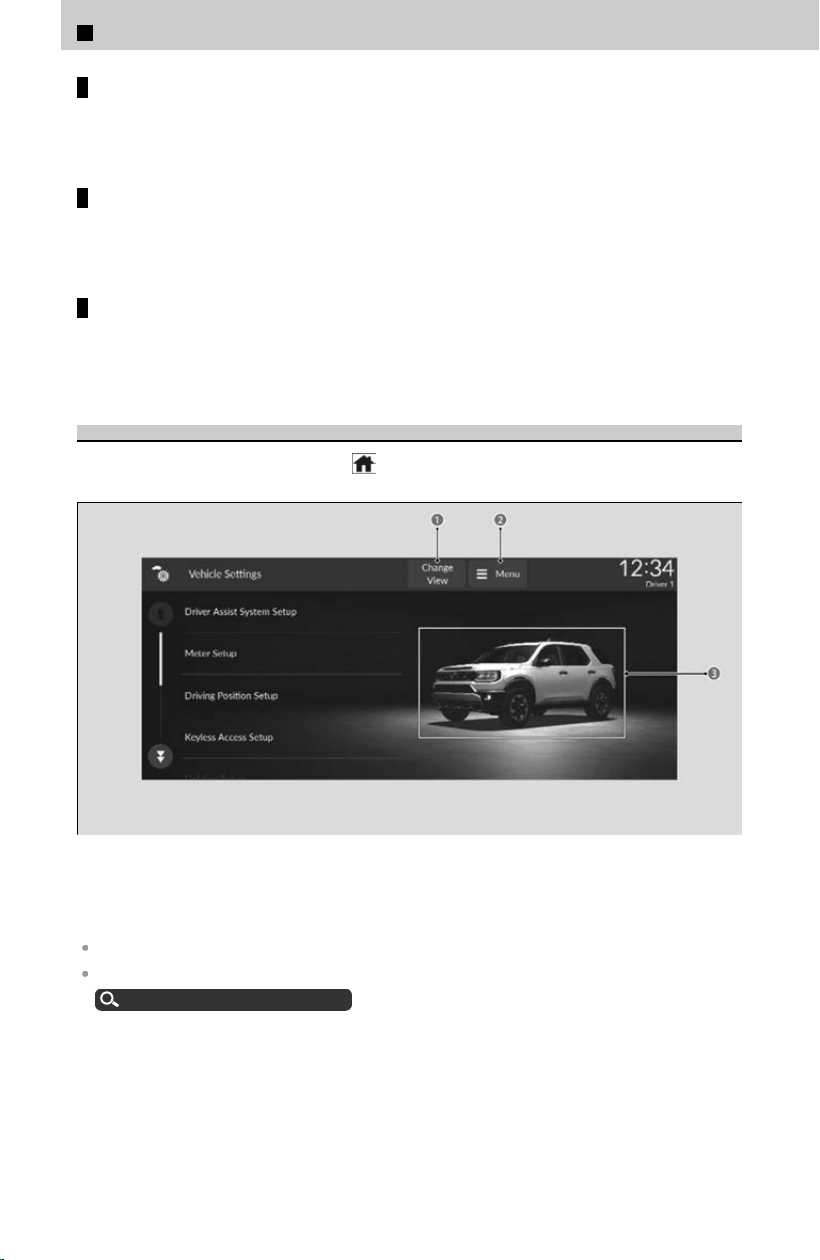
Security
You can customize security settings. Please c
onfirm the details on the audio/
information screen. Specifications are subject to change via system updates, etc.
Google
You can customize Google settings. Please c
onfirm the details on the audio/
information screen. Specifications are subject to change via system updates, etc.
Advanced Settings
You can customize advanced system settings. Please c
onfirm the details on the
audio/information screen. Specifications may be changed via system updates, etc.
How to Customize the Vehicle Settings
With the power mode in ON, select
(Home) icon ➔ Vehicle Settings ➔ setting
item.
a Change View Icon
b Menu Icon
c 3D vehicle image
You can change vehicle image by selecting Change View.
You can change the color of the vehicle image by selecting the Menu.
Vehicle Color Settings
u
P.247
3
Controls > 12.3″ Color Touchscreen
244

List of Customizable Options
Driver Assist System Setup
Forward Collision Warning Distance
Long/Normal
*1
/Short
ACC Forward Vehicle Detect Beep
On/Off
*1
Road Departure Mitigation Setting
Narrow/Normal
*1
/Wide/Warning Only
Lane Keeping Assist Suspend Beep
On/Off
*1
Blind Spot Information
Audible And Visual Alert
*1
/Visual
Alert
Traffic Sign Recognition System
Display Setting
On
*1
/Off
Traffic Sign Recognition System
Speed Limit Warning
On/Off
*1
Speed Limit Warning Threshold
Setting
Speed Limit
*1
/Speed Limit +3mph/
Speed Limit +5mph/Speed Limit
+10mph (When mph is selected)
Speed Limit
*1
/Speed Limit +5km/h/
Speed Limit +10km/h/Speed Limit
+15km/h (When km/h is selected)
Driver Attention Monitor
Tactile And Audible Alert
*1
/Tactile
Alert/Off
Rear Sensor Setting
On
*1
/Off
*1: Default Setting.
Meter Setup
Adjust Outside Temp. Display
-5°F ~ ±0°F
*1
~ +5°F (U.S.)
-3°C ~ ±0°C
*1
~ +3°C (Canada)
“Trip A” Reset Timing
When Fully Refueled/IGN Off/
Manually Reset
*1
“Trip B” Reset Timing
When Fully Refueled/IGN Off/
Manually Reset
*1
Adjust Alarm Volume
High/Mid
*1
/Low
Reverse Alert Tone
On
*1
/Off
Fuel Efficiency Backlight
On
*1
/Off
Turn by Turn Auto Display
On
*1
/Off
Rear Seat Reminder
On
*1
/Off
Speed/Distance Units
km/h · km/mph · miles
*1
(U.S.)
km/h · km
*1
/mph · miles (Canada)
*1: Default Setting.
3
Controls > 12.3″ Color Touchscreen
245
3
Controls

Driving Position Setup
Memory Position Link
On
*1
/Off
Seat Position Movement At Entry/
Exit
On
*1
/Off
*1: Default Setting.
Keyless Access Setup
Door Unlock Mode
Driver Door Only
*1
/All Doors
Keyless Access Light Flash
On
*1
/Off
Keyless Access Beep
On
*1
/Off
Remote Start System On/Off
On
*1
/Off
Lockout Prevention
On
*1
/Off
*1: Default Setting.
Lighting Setup
Auto High-Beam
On
*1
/Off
Interior Light Dimming Time
60sec/30sec
*1
/15sec
Headlight Auto Off Timer
60sec/30sec/15sec
*1
/0sec
Auto Light Sensitivity
*
Max/High/Mid
*1
/Low/Min
Auto Headlight On with Wiper On
On
*1
/Off
*1: Default Setting.
Door Setup
Auto Door Lock
With Vehicle Speed
*1
/Shift From P/
Off
Auto Door Unlock
All Doors When Driver’s Door
Opens
*1
/All Doors With Shift To P/All
Doors with IGN Off/Off
Walk Away Auto Lock
On/Off
*1
Keyless Lock Answer Back
On
*1
/Off
Security Relock Timer
30sec
*1
/60sec/90sec
Auto Folding Door Mirror
*
On
*1
/Off
Keyless Remote Power Window
Control
On
*1
/Off
Lock Presetting
On
*1
/Off
*1: Default Setting.
Power Tailgate Setup
Keyless Open Mode
Anytime*
1
/When Unlocked
Power Open By Outer Handle
OFF (Manual Only)/ON (Power/
Manual)
*1
*: Not available on all models
3
Controls > 12.3″ Color Touchscreen
246
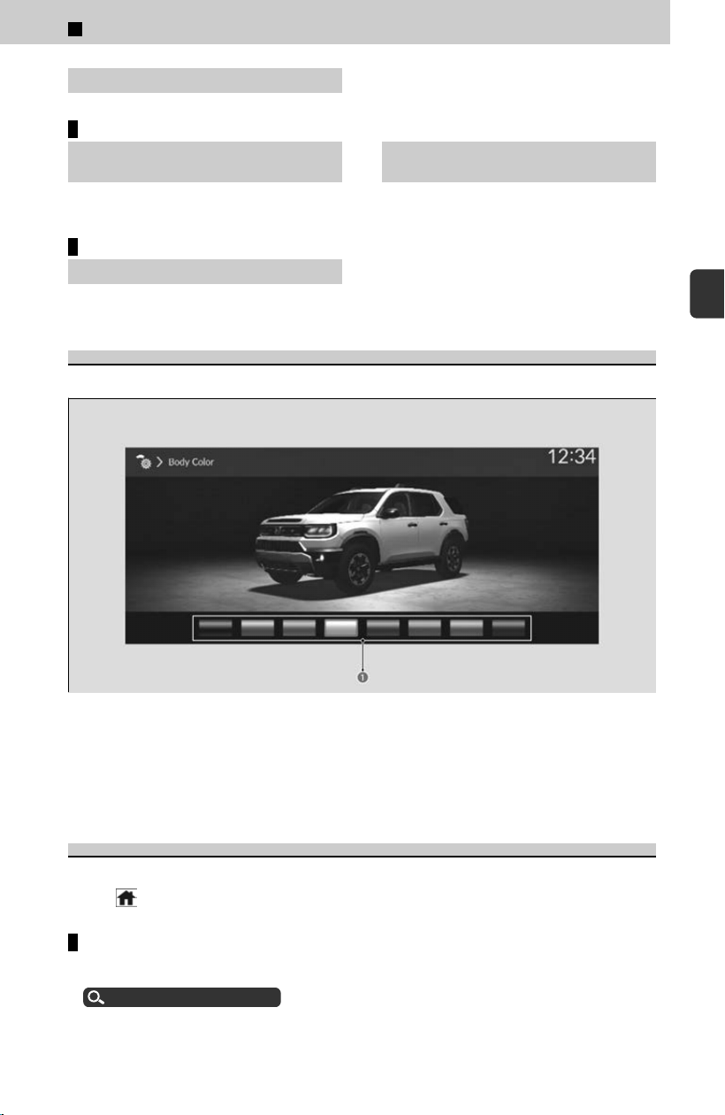
Hands Free Access Function
*
On
*1
/Off
*1: Default Setting.
Climate Control Setup
Driver Seat automatic Climate
Control
On
*1
/Off
Passenger Seat automatic Climate
Control
On
*1
/Off
*1: Default Setting.
Maintenance Info.
Maintenance Info.
Select Reset Items
Vehicle Color Settings
You can change the body color of the vehicle image on the vehicle settings screen.
a Color
[1] Select Menu.
[
2] Select Body Color.
[3] Select desired color.
How to Customize the Profile Settings
You can add and change users, as well as customize user settings.
Select
(Home) icon ➔ Profile Settings ➔ setting item.
Change Profile
You can change and add users.
User Information
u
P.232
*: Not available on all models
3
Controls > 12.3″ Color Touchscreen
247
3
Controls
Manage Profile
Use Manag
e Profile to change profile settings. Please confirm the details on the
audio/information screen.
Specifications are subject to change via system updates, etc.
Driving Position Setting
By adjusting the seating position and then pressing the Memory 1 or Memory 2
but
ton, you can store or recall up to 2 driving positions per user.
Driving Position Memory System
u
P.70
Refer to the following for details on how to adjust seating position.
Adjusting the Front Seat Positions
u
P.66
Defaulting All the Settings
Reset all the menu and customized settings to their factory defaults.
If you perform Factory Data Reset, it will reset the preinstalled apps to their factory default.
If you perform Factory Data Reset, you cannot use the HondaLink® because it goes offline.
HondaLink®
u
P.221
!
When you transfer the vehicle to a third-party, reset all settings to
defaul
t and delete all personal data.
Defaulting General Settings
Only the Owner user can execute.
If you are not the Owner user, please switch users.
Switching Users
u
P.233
[1] Select
(Home) icon.
[2] Select General Settings.
[3] Select System.
[4] Select Factory Data Reset.
≫
A confirmation message appears on the screen.
[5] Select Continue t
o reset the settings.
[6] Select Continue again to reset the settings.
≫
The system will reboot.
Defaulting Vehicle Settings
[1] Select
(Home) icon.
[2] Select Vehicle Settings.
[3] Select Menu.
[4] Select Default All.
[5] Select Yes.
3
Controls > 12.3″ Color Touchscreen
248

3
Controls >
General Information on the Audio System
Compatible iPod, iPhone, and USB Flash
Drives
The following information was made based on the most up-to-date information at the
time this manual w
as written. There may be some discrepancies with updated
versions of the audio system.
iPod and iPhone Model Compatibility
Model
Made for iPod touch (6th generation)/iPod touch (7th generation)
Made for iPhone 5s/iPhone 6/iPhone 6 Plus/iPhone 6s/iPhone 6s Plus/iPhone SE/iPhone 7/
iPhone 7 Plus
/iPhone 8/iPhone 8 Plus/iPhone X/iPhone XS/iPhone XS Max/iPhone XR/iPhone
11/iPhone 11 Pro/iPhone 11 Pro Max/iPhone SE (2nd generation)/iPhone 12 mini/iPhone 12/
iPhone 12 Pro/iPhone 12 Pro Max/iPhone 13 mini/iPhone 13/iPhone 13 Pro/iPhone 13 Pro
Max/iPhone SE (3rd generation)/iPhone 14/iPhone 14 Plus/iPhone 14 Pro/iPhone 14 Pro Max
This system may not work with all software versions of these devices.
Compatible USB Flash Drives
Please use a recommended USB flash drive of 256 MB or higher formatted with
F
AT16 or FAT32.
Some digital audio players may not be compatible.
Some USB flash drives (e.g., a device with security lockout) may not work.
Some software files may not allow for audio play or text data display.
Some versions of MP3, WMA, AAC, FLAC, WAV or Opus formats may be unsupported.
Files on the USB flash drive are played in their stored order. This order may be different from
the order displayed on your PC or device.
Only AAC format files recorded with iTunes are playable on this unit.
249
3
Controls

Honda App License Agreement
END USER LICENSE AGREEMENT
PLEASE CAREFULLY READ THIS END USER LICENSE AGREEMENT (THIS
“
AGREEMENT”) WHICH GOVERNS YOUR USE OF THE SOFTWARE INSTALLED ON
YOUR HONDA OR ACURA VEHICLE (YOUR “VEHICLE”) AS WELL AS THE
APPLICATIONS, SERVICES, FUNCTIONS, AND CONTENT PROVIDED THROUGH THE
SOFTWARE (COLLECTIVELY, THE “SERVICES”). YOUR USE OF THE SOFTWARE OR
SERVICES WILL SERVE AS YOUR CONSENT TO THE TERMS OF THIS AGREEMENT.
THE SOFTWARE IS OWNED (OR LICENSED), PROVIDED, AND/OR OPERATED BY
AMERICAN HONDA MOTOR CO. INC., (“HONDA,” “US,” “WE,” OR “OUR”), WITH ITS
BUSINESS ADDRESS AT 1919 TORRANCE BLVD., TORRANCE, CA 90501. REFERENCE
TO “HONDA” IN THIS AGREEMENT INCLUDES HONDA’S PARENT COMPANY AND ITS
AFFILIATES AND DESIGNATED AGENTS. THE SERVICES ARE OWNED (OR
LICENSED), PROVIDED, AND/OR OPERATED BY HONDA OR A THIRD-PARTY SERVICE
PROVIDER (A “PROVIDER”). REFERENCE TO A “PROVIDER” IN THIS AGREEMENT
INCLUDES SUCH PROVIDER’S PARENT COMPANY, AFFILIATES, AND DESIGNATED
AGENTS.
A. Description of the Software. The SOFTWARE includes the software, firmware and
the like, installed and executing on your VEHICLE during manufacture, and thereafter
updated from time to time by HONDA, you or an authorized HONDA dealer (a
“DEALER”). The SOFTWARE allows you to access and use a variety of SERVICES,
including but not limited to: (a) HONDA applications, services, and content provided
through the SOFTWARE (together, “HONDA SERVICES”); and (b) PROVIDER
applications, services, and content provided through the SOFTWARE (together,
“PROVIDER SERVICES”), each of which may provide access to various information,
media, content, and services.
B. SOFTWARE Licensing and Intellectual Property.
1. SOFTWARE. This AGREEMENT grants you a non-exclusive, limited, and revocable
license to use the SOFTWARE and SERVICES solely (a) as installed on your VEHICLE
by HONDA, (b) as updated on your Vehicle by HONDA, you (but only as and when
directed by HONDA), or a DEALER and (c) as permitted under the terms of this
AGREEMENT.
2. HONDA Services. The SOFTWARE may provide you with access to various HONDA
SERVICES. Installation, activation, or use of HONDA SERVICES may require your
consent to additional terms, conditions, and privacy policies applicable to those
HONDA SERVICES (the “HONDA TERMS”). You acknowledge and agree that any
collection, use, sharing of data generated by your VEHICLE or your use of your
VEHICLE, and your use of the HONDA SERVICES shall be subject to this AGREEMENT
and any additional HONDA TERMS that may be specifically applicable to such HONDA
SERVICES or data generation. The HONDA SERVICES may collect, use, and share
such data while you are using the SOFTWARE.
3
Controls > General Information on the Audio System
250

3. Open-Source Software. The SOFTWARE and SERVICES may incorporate software
licensed to HONDA under free or open-source licenses which govern HONDA’s
distribution and your use of such software. HONDA and the third-party authors,
licensors, and distributors of such software disclaim all warranties and all liability
arising from any and all use or distribution of the software. To the extent such
software is provided under terms that differ from the applicable free or open-source
licenses, those terms are offered by HONDA alone. Additional information regarding
free and open-source software incorporated in the SOFTWARE and SERVICES is
available in this manual or within the SOFTWARE.
4. Provider Services. The SOFTWARE may provide you with access to various
PROVIDER SERVICES. Installation or use of such PROVIDER SERVICES may require
your consent to additional terms, conditions, and privacy policies of the applicable
PROVIDER (the “PROVIDER TERMS”). This AGREEMENT restricts the manner in which
you can install and use PROVIDER SERVICES but does not grant you a license or
permission to use such PROVIDER SERVICES. Your permission to use PROVIDER
SERVICES is limited and subject to any license grants, conditions, and limitations
included in the PROVIDER TERMS. You acknowledge that any collection, use, sharing
of your information, targeted advertising practices by PROVIDERS, and your use of the
PROVIDER SERVICES shall be subject to both this AGREEMENT and any applicable
PROVIDER TERMS. The PROVIDER SERVICES may collect, use, and share such
information while you are using the SOFTWARE.
5. License Limitations and Restrictions on Use.
(a) Limited License. You understand and agree that the SOFTWARE and SERVICES are
licensed, not sold, to you solely for use in accordance with this AGREEMENT and any
applicable PROVIDER TERMS, and any documentation for the VEHICLE made
available to you by HONDA (any “DOCUMENTATION”). HONDA and its licensors
reserve all rights in the SOFTWARE and HONDA SERVICES not expressly granted to
you under this AGREEMENT. PROVIDERS and their licensors reserve all rights in the
PROVIDER SERVICES not expressly granted to you under the applicable PROVIDER
TERMS.
(b) Restrictions on Use. The licenses granted under this AGREEMENT do not permit
you to use the SOFTWARE or SERVICES on a device other than your VEHICLE. As a
condition of using the SOFTWARE and SERVICES, you agree that you may not and will
not:
(1) copy, download, distribute, modify, publish, sell, rent, lease, lend, license, sublicense,
r
euse, or create derivative works of the SOFTWARE or SERVICES or any of the content or
other material within the SOFTWARE or SERVICES, including without limitation, HONDA or
PROVIDER names, logos, or any other trademarks of HONDA or PROVIDERS or used in
association with the SOFTWARE or any SERVICES, except as required to use the SOFTWARE
or SERVICES in accordance with this AGREEMENT, any applicable PROVIDER TERMS, and
the DOCUMENTATION;
3
Controls > General Information on the Audio System
251
3
Controls

(2) access or use the SOFTWARE or SERVICES in any manner intended to damage or impair
the operation of the SOFTWARE or SERVICES or interfere with anyone else’s use and
enjoyment of the SOFTWARE or SERVICES;
(3) access or attempt to access any system or server on which the SOFTWARE or SERVICES
is hos
ted or modify or alter the SOFTWARE or SERVICES in any way;
(4) use the SOFTWARE or SERVICES for any unlawful purpose, or in violation of any third
par
ty rights;
(5) use the SOFTWARE or SERVICES in violation of any applicable tr
affic regulations, rules or
laws, including but not limited to any driver distraction laws, rules or regulations;
(6) violate the terms of this AGREEMENT, any HONDA TERMS, any PROVIDER TERMS or
other applicable thir
d-party terms, conditions, and privacy policies; or
(7) reverse engineer, decompile, disassemble, attempt to derive the source code of, nor
permit others t
o reverse engineer, decompile, or disassemble, or attempt to derive the
source code of the SOFTWARE or SERVICES, except and only to the extent that such activity
is expressly permitted (a) by applicable law notwithstanding this limitation or (b) the terms
of applicable free or opensource software licenses.
6. Intellectual Property Rights. Al
l title and intellectual property rights in and to the
SOFTWARE and SERVICES, the accompanying DOCUMENTATION, and all copies of
the SOFTWARE or SERVICES are owned by HONDA, PROVIDERS, or their suppliers or
licensors. This AGREEMENT does not grant you any rights in connection with any
trademarks or service marks of HONDA, PROVIDERS, or their licensors, affiliates, or
suppliers.
7. Export Restrictions: You acknowledge that the SOFTWARE and SERVICES are
subject to U.S., European Union, and other export jurisdictions. You agree to comply
with all applicable international and national laws that apply to the SOFTWARE and
SERVICES, including the U.S. Export Administration Regulations, as well as end-user,
end-use, and destination restrictions issued by the U.S. and other governments.
C. SOFTWARE Operation
1. HONDA reserves the right to suspend or terminate your access to and use of the
SOFTWARE or SERVICES if you are found to be in violation of this AGREEMENT or as
reasonably deemed necessary by HONDA.
2. Eligibility/Registration/Activation. The SOFTWARE is intended for and available to
individuals who (a) are of legal age of majority in their jurisdiction of residence (and at
least 18 years of age), or are younger than 18 years of age and possess a valid
driver’s license issued by their jurisdiction of residence, and (b) own or have
permissive access to a compatible VEHICLE. We do not knowingly collect any
information, including personal information, from children under 13. If we learn or are
notified that we have collected personal information of a child under 13, we will
immediately take steps to delete such information.
3
Controls > General Information on the Audio System
252

3. Use of PROVIDER SERVICES through the SOFTWARE. Certain PROVIDER
SERVICES made available through the SOFTWARE may require that you register or
otherwise have an account with the PROVIDER and agree to PROVIDER TERMS. Any
use of any of such PROVIDER SERVICES within the SOFTWARE is subject to this
AGREEMENT and the applicable PROVIDER TERMS. HONDA does not exercise control
over such PROVIDER SERVICES and is not responsible or liable for the availability,
security, or content of such PROVIDER SERVICES, and the inclusion of any PROVIDER
SERVICES does not imply a referral from, the approval of, or the endorsement by
HONDA of such PROVIDER SERVICES. HONDA is not responsible or liable, directly or
indirectly, for any damage relating to or resulting from your use of the PROVIDER
SERVICES.
4. Links to Third Party Sites: The SOFTWARE may provide you with the ability to
access third-party sites and content through the use of the SOFTWARE or SERVICES.
The third-party sites and content are not under the control of HONDA. HONDA is not
responsible or liable, directly or indirectly, for such third-party websites and their
content or for any damage relating to or resulting from your access or use of such
websites and content.
5. Unauthorized Use and Abuse. You are responsible for ensuring your (and any
authorized third parties’) use of the SOFTWARE and SERVICES remains in compliance
with this AGREEMENT and all other applicable HONDA TERMS and PROVIDER
TERMS. You acknowledge and agree that any use of the SOFTWARE or SERVICES
occurring through your VEHICLE will be deemed your actions and that HONDA and
PROVIDERS may rely upon such actions. You agree to immediately notify us if you
suspect fraudulent or abusive activity involving the SOFTWARE or SERVICES. If you so
notify us or if we otherwise suspect fraudulent or abusive activity, you agree to
cooperate with us in any fraud investigation and to use any fraud prevention
measures we prescribe. Your failure to immediately notify us or cooperate to use such
measures will result in your liability for all fraudulent usage or abusive activity
associated with your VEHICLE.
6. SOFTWARE Updates. The SOFTWARE and SERVICES may be updated when your
VEHICLE is serviced by a DEALER or remotely, over-the-air, by HONDA from time to
time; such updates may occur with or without further notice or your future consent.
The SOFTWARE may be updated at HONDA’s discretion and for any purpose
including, without limitation, to patch or otherwise improve the SOFTWARE or
SERVICES functionality, security, or stability. All updates to the SOFTWARE and
SERVICES are subject to this AGREEMENT and any other applicable HONDA TERMS
and PROVIDER TERMS.
7. Uninstalling, Removing, and Replacing the SOFTWARE. Replacing SOFTWARE or
HONDA SERVICES with software or firmware not provided and installed by HONDA or
a DEALER will render all representations and warranties for the SOFTWARE, HONDA
SERVICES, and VEHICLE functionality reliant upon the SOFTWARE or HONDA
SERVICES null and void.
3
Controls > General Information on the Audio System
253
3
Controls

D. SOFTWARE Operational Notices and Warnings
1. Vehicle Geolocation Information. You acknowledge that your VEHICLE may be
equipped with certain traffic and map features. The traffic feature will automatically
collect and transmit, through GPS technology, your Vehicle’s current location
(longitude and latitude), travel direction and speed (“VEHICLE GEOLOCATION
INFORMATION”) to HONDA and PROVIDERS. The VEHICLE GEOLOCATION
INFORMATION is used by HONDA and PROVIDERS to provide traffic and navigation-
related information to you, but may also be used to provide other SERVICES or offers
to you. HONDA will not use such VEHICLE GEOLOCATION INFORMATION for its own
marketing efforts, or provide such information to unaffiliated third parties for their
own purposes, without your express consent.
2. Potential Map Inaccuracy and Route Safety. Maps used by this system may be
inaccurate because of changes in roads, traffic controls, routing, or driving conditions.
Always use good judgment and common sense when following suggested routes. Do
not follow the route suggestions if doing so would result in an unsafe or illegal driving
maneuver, if you would be placed in an unsafe situation, or if you would be directed
into an area that you consider unsafe. Do not rely on any navigation features included
in the system to route you to emergency services. Not all emergency services such as
police, fire stations, hospitals, or clinics are likely to be contained in the map database
for such navigation features. Ask local authorities or an emergency services operator
for such locations and routes. The driver is ultimately responsible for the safe
operation of the vehicle and therefore, must evaluate whether it is safe to follow the
suggested directions. Any navigation features are provided only as an aid. Make your
driving decisions based on your observations of local conditions and existing traffic
regulations. Navigation features are not a substitute for your personal judgment. Any
route suggestions made by the SOFTWARE or SERVICES should never replace any
local traffic regulations or your personal judgment or knowledge of safe driving
practices.
3. Speech Recognition: You acknowledge and understand that HONDA and
PROVIDERS may record, retain, and use voices commands when you use the speech
recognition components of the SOFTWARE or SERVICES. You and all VEHICLE
operators and passengers (a) consent to the recording and retention of voice
commands in support of providing speech recognition components and (b) release
HONDA and PROVIDERS from all claims, liabilities, and losses that may result from
any use of such recorded voice commands. Recognition errors are inherent in speech
recognition. It is your responsibility to monitor any speech recognition functions
included in the system and address any errors. Neither HONDA nor PROVIDERS will
be liable for any damages arising out of errors in the speech recognition process.
3
Controls > General Information on the Audio System
254

4. Distraction Hazards. Navigation features may require manual (non-verbal) input or
setup. Attempting to perform such set-up or insert data while driving can seriously
distract your attention and could cause a crash or other serious consequences; the
ability to undertake such interactions may also be limited by state or local law, which
laws you are responsible to know and follow. Even occasional short scans of the
screen may be hazardous if your attention has been diverted away from your driving
at a critical time. Pull over and stop the vehicle in a safe and legal manner before
attempting to access a function of the system requiring prolonged attention. Do not
raise the volume excessively. Keep the volume at a level where you can still hear
outside traffic and emergency signals while driving. Driving while unable to hear these
sounds could result in a crash.
E. Information Collection and Storage
1. Information Collection, Use, Transmission and Storage of Data. Consent to Use of
Data: You agree that HONDA and PROVIDERS may collect and use your information
gathered in any manner as part of product support services related to the SOFTWARE
or related services. HONDA may share such information with third parties, including,
without limitation, PROVIDERS, third party software and services suppliers, their
affiliates and/or their designated agents, solely to improve their products or to provide
services or technologies to you. HONDA, third party software and systems suppliers,
their affiliates and/or their designated agent may disclose this information to others,
but not in a form that personally identifies you.
2. Information Storage. Depending on the type of multimedia system you have in your
VEHICLE, certain information may be stored for ease of use of the SOFTWARE
including, without limitation, search history, location history in certain applications,
previous and saved destinations, map locations within certain applications, and
device numbers and contact information.
(a) Vehicle Health Information. Your VEHICLE may remotely transmit information
regarding the status and health of your VEHICLE (“VEHICLE INFORMATION”) to
HONDA without notification to you. VEHICLE INFORMATION may contain VEHICLE
maintenance and malfunction status that is derived from VEHICLE diagnostic data
and includes, but is not limited to, status of powered doors and windows, battery life
data, battery charging data, VEHICLE speed, coolant temperature, air compressor
revolution, output power, warning codes, diagnostic trouble codes, fuel injection
volume, and engine rotations per minute. VEHICLE HEALTH INFORMATION may be
used by HONDA for research and development, to deliver HONDA SERVICES and
information to you, and to contact you, and is retained only for a period of time
necessary to fulfill these goals.
(b) VEHICLE Geolocation Data (non-navigation/map based). If you opt-in to
geolocation-based SERVICES, your vehicle’s geolocation data (latitude and longitude)
will be automatically sent from your VEHICLE to HONDA and PROVIDERS.
3
Controls > General Information on the Audio System
255
3
Controls

(c) You understand that the inputting or uploading of information to your VEHICLE’s
multimedia system or the SOFTWARE or SERVICES is at your own risk and that
HONDA is not responsible for unauthorized access to or use of any personal or other
information. All information uploaded to the SOFTWARE and SERVICES may be
stored on your VEHICLES’s multimedia system and you understand that the security
and safety of your VEHICLE’s multimedia system is your sole responsibility.
F. NO WARRANTY. You understand and agree that your use of the SOFTWARE and
SERVICES are solely at your own risk and that you will be solely responsible for any
damage to your VEHICLE’s multimedia system or any other equipment or any loss of
data that may result from your use of the SOFTWARE or SERVICES. THE SOFTWARE
AND SERVICES ARE PROVIDED ON AN “AS IS” AND “AS AVAILABLE” BASIS
WITHOUT ANY WARRANTY OF ANY KIND, EXPRESSED, IMPLIED OR STATUTORY. WE
SPECIFICALLY DISCLAIM ANY IMPLIED WARRANTIES OF MERCHANTABILITY,
FITNESS FOR A PARTICULAR PURPOSE, AND NON-INFRINGEMENT. HONDA makes
no warranties that the SOFTWARE or SERVICES will meet your requirements, or that
the SOFTWARE or SERVICES will be uninterrupted, timely, secure, non-infringing or
error free. You understand and agree that you are responsible for any and all charges,
costs or expenses associated with your use of the SOFTWARE or SERVICES. Advice or
information, whether oral or written, obtained by you from us or through the
SOFTWARE or SERVICES are provided for informational purposes only and will not
create any warranty not expressly made herein. You should not rely on any such
information or advice. We assume no liability or responsibility for any errors or
omissions in the SOFTWARE or SERVICES. We do not make any warranty or
representation that your use of the material displayed on, or obtained through, the
SOFTWARE or SERVICES is non-infringing of any rights of any third party. Any decision
or action taken by you on the basis of information or content provided via the
application is at your sole discretion and risk. HONDA and PROVIDERS are not
responsible or liable for any such decision, or for the accuracy, completeness,
usefulness, or availability of any content or information displayed, transmitted, or
otherwise made available via the SOFTWARE or SERVICES. To the extent jurisdictions
do not allow the exclusion of certain warranties, some of the above exclusions may
not apply to you.
G. LIMITATIONS ON LIABILITY. You and HONDA are each waiving important rights.
1. Limitations on YOUR liability. HONDA cannot recover from you any consequential,
indirect, incidental, or special damages, or attorney’s fees in connection with your use
of the SOFTWARE or HONDA SERVICES. HONDA WAIVES TO THE FULLEST EXTENT
ALLOWED BY LAW ANY CLAIM FOR DAMAGES OTHER THAN DIRECT,
COMPENSATORY DAMAGES AS LIMITED IN THIS AGREEMENT.
3
Controls > General Information on the Audio System
256

2. Limitation on HONDA and PROVIDER liability. Neither HONDA nor PROVIDERS will
be liable to you or any other party for consequential, indirect, incidental, special, or
punitive damages (including without limitation lost profits) in connection with your
use of the SOFTWARE or SERVICES, even if HONDA or PROVIDERS are aware of the
possibility of such damages. These limitations apply to all claims, including, without
limitation, claims in contract and tort (such as negligence, product liability and strict
liability). To the extent that a jurisdiction does not permit the exclusion or limitation of
liability as set forth herein our liability is limited to the maximum extent permitted by
law in such states. If HONDA or PROVIDERS are found liable to you for any reason,
you agree that the aggregate liability of all these parties to you for any claim is limited
to ten U.S. dollars (US $10.00). Neither HONDA nor any PROVIDER would have
agreed to provide the SOFTWARE or SERVICES to you if you did not agree to this
limitation. This amount is the sole and exclusive liability of HONDA and PROVIDERS to
you, and is payable as liquidated damages and not as a penalty. Except where
prohibited by law, you may not bring any claim against HONDA or any third-party
beneficiary more than two (2) years after the claim arises. We do not have any liability
for SOFTWARE or SERVICES interruptions of any length.
(a) Release of HONDA and PROVIDERS For yourself and anyone else claiming under
you, you agree to release and discharge HONDA, PROVIDERS, their respective
officers, directors, and employees, and each third-party beneficiary from all claims,
liabilities and losses in connection with the SOFTWARE or SERVICES, including, but
not limited to claims for personal injury or property damage arising from the total or
partial failure of performance of the SOFTWARE or SERVICES, even if caused by or
based upon the negligence, gross negligence, strict products liability, Deceptive Trade
Practices Act violations, bad faith, or breach of warranty of us or the malfunction of
the SOFTWARE or SOFTWARE SERVICES. YOU AGREE TO WAIVE TO THE FULLEST
EXTENT ALLOWED BY LAW, ANY CLAIM FOR DAMAGES OTHER THAN DIRECT,
COMPENSATORY DAMAGES AS LIMITED IN THIS AGREEMENT. YOU HEREBY
RELEASE AND DISCHARGE HONDA AND ITS LICENSORS AND CONTRACTORS
(INCLUDING ANY THIRD PARTIES PROVIDING ALL OR PART OF THE SOFTWARE OR
SERVICES) FROM AND AGAINST ANY CLAIMS, DAMAGES, EXPENSES AND LIABILITY
ARISING FROM OR RELATED TO ANY INJURIES, DAMAGES, OR LOSSES TO ANY
PERSON (INCLUDING DEATH) OR PROPERTY OF ANY KIND RESULTING IN WHOLE
OR PART, DIRECTLY OR INDIRECTLY, FROM YOUR USE OF THE SOFTWARE OR
SERVICES.
H. Survival. You agree that the limitations of liability and indemnities in this
AGREEMENT will survive even after the AGREEMENT has ended. These limitations of
liability apply not only to you, but to anyone using the SOFTWARE or SERVICES via
your VEHICLE, to anyone making a claim on your behalf, and to any claims made by
your family, employees, customers, or others arising out of or relating to your
VEHICLE, the SOFTWARE, or SERVICES.
3
Controls > General Information on the Audio System
257
3
Controls

I. Availability/Interruption. The SOFTWARE and certain SERVICES are made
available through your VEHICLE’s compatible multimedia system when the VEHICLE
is turned on. Certain SERVICES may be available only through your compatible mobile
device when it is within the operating range of the VEHICLE and a wireless carrier.
The availability of the SOFTWARE and SERVICES may be subject to transmission
limitation or interruption, including but not limited to technical obsolesce or
sunsetting of the hardware, software or firmware, inside of or external to the Vehicle,
required for data transmission or receipt. HONDA does not guarantee that the
SOFTWARE, SERVICES, or any portion thereof will be available at all times or in all
areas. You acknowledge and agree that HONDA is not responsible for performance
degradation, interruption or delays. You acknowledge that HONDA shall not be liable
to you if the SOFTWARE or SERVICES in a given location are not available. If the
SOFTWARE or SERVICES are not available within your intended location, you agree
that your sole remedy shall be to cease using the SOFTWARE and SERVICES.
J. PRODUCT SUPPORT: Product support for the SOFTWARE is provided by HONDA.
For product support, please refer to HONDA instructions provided in the
DOCUMENTATION. Should you have any questions concerning this AGREEMENT, or if
you desire to contact HONDA for any other reason, please refer to the HONDA contact
information provided in the DOCUMENTATION.
K. Termination and Transfer.
1. Termination. This AGREEMENT is effective until terminated by you or US. WE may
terminate this AGREEMENT for any or no reason, and with or without notice to you.
Your rights under this AGREEMENT will terminate automatically without notice from
US if you fail to comply with any term of this AGREEMENT. Upon termination of this
AGREEMENT, you shall cease all use of the SOFTWARE and SERVICES.
2. Transfer: You may permanently transfer your rights under this AGREEMENT only
as part of a sale or transfer of the VEHICLE, provided you retain no copies, you
transfer all of the SOFTWARE and HONDA SERVICES (including all component parts,
the media and printed materials, and any upgrades), and the recipient agrees to the
terms of this AGREEMENT. You agree to notify HONDA upon the sale or transfer of the
VEHICLE. To contact HONDA, please refer to the HONDA contact information
provided in the DOCUMENTATION.
L. Changes to the SOFTWARE or SERVICES. WE may change, modify, or update the
SOFTWARE or SERVICES from time to time. Unless explicitly stated otherwise, any
new features or services that augment or enhance the SOFTWARE or SERVICES in the
future shall respectively be considered part of the SOFTWARE or SERVICES and
subject to this AGREEMENT. WE reserve the right at any time and from time to time to
interrupt, restrict, modify, suspend, discontinue, temporarily or permanently, the
SOFTWARE or SERVICES (or any portion thereof), with or without notice to you, and
you agree that HONDA shall not be liable to you or to any third party for any
modification, suspension or discontinuance of the SOFTWARE or SERVICES.
M. ARBITRATION:
3
Controls > General Information on the Audio System
258

PLEASE READ THIS ARBITRATION PROVISION CAREFULLY TO UNDERSTAND YOUR
RIGHTS. YOU AGREE THAT ANY CLAIM THAT YOU MAY HAVE IN THE FUTURE MUST BE
RESOLVED THROUGH BINDING ARBITRATION. YOU WAIVE THE RIGHT TO HAVE YOUR
DISPUTE HEARD IN COURT AND WAIVE THE RIGHT TO BRING CLASS CLAIMS. YOU
UNDERSTAND THAT DISCOVERY AND APPEAL RIGHTS ARE MORE LIMITED IN
ARBITRATION.
Arbitration is a method of resolving a claim, dispute or controversy without filing a law
suit.
By agreeing to arbitrate, the right to go to court is waived and instead claims, disputes or
controversies are submitted to binding arbitration. This provision sets forth the terms and
conditions of our agreement. YOU and HONDA agree and acknowledge that this Agreement
affects interstate commerce and the Federal Arbitration Act (“FAA”) applies. By using the
Software, Vehicle, or Services, YOU elect to have disputes resolved by arbitration.
YOU, HONDA or any involved third party may pursue a Claim. “Claim” means any dispute
betw
een YOU, HONDA, or any involved third party relating to your use of the Software, the
Vehicle, or the Services, this Agreement, or our relationship, including any representations,
omissions or warranties. “Claim” does not include personal injury or wrongful death claims.
YOU or HONDA may seek remedies in small claims court or provisional judicial remedies
without arbitrating. In addition, notwithstanding anything herein to the contrary, YOU or
HONDA may seek equitable relief in a court of competent jurisdiction.
YOU or HONDA may select arbitration with American Arbitration Association, JAMS or
National Arbitr
ation and Mediation. Contact these sponsors for their rules. The hearing will
be in the federal district where YOU reside. If agreed, it may be by telephone or written
submissions. Filing and arbitrator fees to be paid per the sponsor rules. You may contact the
sponsor for a fee waiver. If no fee waivers, HONDA will pay filing and arbitrator fees up to
$5,000, unless law requires more. Each party is responsible for other fees. Arbitrator may
award costs or fees to prevailing party, if permitted by law. HONDA will not seek fees, unless
the claims are frivolous.
Arbitrator shall be an attorney or current or retired judge familiar with automotive or
c
onsumer software. The arbitrator shall follow substantive law, statute of limitations and
decide all issues relating to the interpretation, construction, enforceability and applicability
of this provision. The arbitrator may order relief permitted by law. This provision is governed
and enforceable by the FAA. An award shall include a written opinion and be final, subject to
appeal by the FAA.
This provision survives termination of this Agreement or relationship, bankruptcy,
as
signment or transfer. If part of this provision is unenforceable, the remainder remains in
effect. If unenforceability allows arbitration as a class action, then this provision is entirely
unenforceable. You may opt out within 30 days of your initial use of the Software by sending
a signed, written notice to HONDA at American Honda Motor Co., Inc. Honda Automobile
Customer Service Mail Stop CHI-5, 1919 Torrance Blvd. Torrance, CA 90501-2746. HONDA
reserves the right to make changes to this provision after providing written notice and an
opportunity to opt out.
3
Controls > General Information on the Audio System
259
3
Controls

N. Miscellaneous: You may not assign this AGREEMENT without HONDA’s prior
written consent. This AGREEMENT and any additional HONDA TERMS and PROVIDER
TERMS represents the entire agreement between you and US. HONDA may amend
the terms of this AGREEMENT by providing you with notices of such updated terms. If
you do not consent to be bound by the updated terms, your sole remedy will be to
cease using the SOFTWARE and SERVICES. If any part of this AGREEMENT is found
invalid, void, or unenforceable, the balance of the AGREEMENT will remain valid and
enforceable according to its terms. To the fullest extent permitted by law, and except
as explicitly provided otherwise, this AGREEMENT and any disputes arising out of or
relating to it will be governed by the laws of the State of California, except that
California laws concerning choice of law or conflicts shall not apply if they would
cause the substantive law of another jurisdiction to apply. Notwithstanding the
foregoing, Section M shall be governed by the Federal Arbitration Act and the laws of
the State of California, as applicable, as set forth therein. The failure to enforce any
term of this AGREEMENT on one occasion shall not prevent enforcement on any other
occasion or the enforcement of any other term. Headings and captions shall not be
considered included for purposes of interpretation or application hereof, but are for
convenience only.
About Open Source Licenses
To see the open source license information, follow these steps.
[1] Select
(Home) icon.
[2] Select General Settings.
[3] Select Advanced Settings.
[4] Select System.
[5] Select Legal Information.
[6] Select System WebView licenses.
License Information
Bluetooth®
The Bluet
ooth® word mark and logos are registered trademarks owned by Bluetooth
SIG, Inc. and any use of such marks by ALPS ALPINE CO.,LTD is under license. Other
trademarks and trade names are those of their respective owners.
https://www.bluetooth.com/develop-with-bluetooth/marketing-branding/
3
Controls > General Information on the Audio System
260
Windows Media
This product is protected by certain intellectual property rights of Microsoft. Use or
dis
tribution of such technology outside of this product is prohibited without a license
from Microsoft.
Apple
“Made for iPod,” and “Made for iPhone,” mean that an electronic accessory has been
designed t
o connect specifically to iPod, or iPhone, respectively, and has been
certified by the developer to meet Apple performance standards. Apple is not
responsible for the operation of this device or its compliance with safety and
regulatory standards. Please note that the use of this accessory with iPod, or iPhone,
may affect wireless performance.
Apple, the Apple Logo, iPhone, iPod touch are trademarks of Apple Inc., registered in
the U.S. and other countries. Apple CarPlay, iPod, iPhone, iTunes, Siri and Lightning
are trademarks of Apple Inc. App Store is a service mark of Apple Inc.
MPEG
Mpeg4 Visual
THIS PRODUCT IS LICENSED UNDER THE MPEG-4 VISUAL PATENT PORTFOLIO
LICENSE F
OR THE PERSONAL AND NON-COMMERCIAL USE OF A CONSUMER FOR (i)
ENCODING VIDEO IN COMPLIANCE WITH THE MPEG-4 VISUALA STANDARD
(“MPEG-4 VIDEO”) AND/OR (ii) DECODING MPEG-4 VIDEO THAT WAS ENCODED BY
A CONSUMER ENGAGED IN A PERSONAL AND NONCOMMERCIAL ACTIVITY AND/OR
WAS OBTAINED FROM A VIDEO PROVIDER LICENSED BY MPEG LA TO PROVIDE
MPEG-4 VIDEO. NO LICENSE IS GRANTED OR SHALL BE IMPLIED FOR ANY OTHER
USE. ADDITIONAL INFORMATION INCLUDING THAT RELATING TO PROMOTIONAL,
INTERNAL AND COMMERCIAL USES AND LICENSING MAY BE OBTAINED FROM
MPEG LA, LLC.
SEE HTTP://WWW.MPEGLA.COM.
VC-1
THIS PRODUCT IS LICENSED UNDER THE VC-1 PATENT PORTFOLIO LICENSE FOR
THE PERSONAL AND NON-COMMERCIAL USE OF A CONSUMER TO (i) ENCODE
VIDEO IN COMPLIANCE WITH THE VC-1 STANDARD (“VC-1 VIDEO”) AND/OR (ii)
DECODE VC-1 VIDEO THAT WAS ENCODED BY A CONSUMER ENGAGED IN A
PERSONAL AND NON-COMMERCIAL ACTIVITY AND/OR WAS OBTAINED FROM A
VIDEO PROVIDER LICENSED TO PROVIDE VC-1 VIDEO. NO LICENSE IS GRANTED OR
SHALL BE IMPLIED FOR ANY OTHER USE.
3
Controls > General Information on the Audio System
261
3
Controls
ADDITIONAL INFORMATION MAY BE OBTAINED FROM MPEG LA, L.L.C. SEE HTTP://
WWW.MPEGLA.COM.
AVC/H.264
THIS PRODUCT IS LICENSED UNDER THE AVC PATENT PORTFOLIO LICENSE FOR
THE PERSONAL AND NONCOMMERCIAL USE OF A CONSUMER TO (i) ENCODE VIDEO
IN COMPLIANCE WITH THE AVC STANDARD (“AVC VIDEO”) AND/OR (ii) DECODE AVC
VIDEO THAT WAS ENCODED BY A CONSUMER ENGAGED IN A PERSONAL AND NON-
COMMERCIAL ACTIVITY AND/OR WAS OBTAINED FROM A VIDEO PROVIDER
LICENSED TO PROVIDE AVC VIDEO. NO LICENSE IS GRANTED OR SHALL BE IMPLIED
FOR ANY OTHER USE.
ADDITIONAL INFORMATION MAY BE OBTAINED FROM MPEG LA, L.L.C. SEE HTTP://
WWW.MPEGLA.COM.
HD Radio™
HD Radio™ Technology manufactured under license from iBiquity Digital Corporation,
a subsidiar
y of Xperi Inc., U.S. and Foreign Patents. For patents see https://
xperi.com/hd-radio-patents/. Xperi, HD Radio, HD, and ‘ARC’ logos and their
respective logos are trademarks or registered trademarks of Xperi Inc. and its
subsidiaries in the United States and other countries.
3
Controls > General Information on the Audio System
262

Legal Information on Apple CarPlay/Android
Auto
OWNER’S MANUAL LICENSE/LIABILITY STATEMENTS
USE OF APPLE CARPLAY IS SUBJECT TO YOUR AGREEMENT TO THE CARPLAY
TERMS OF USE, WHICH ARE INCL
UDED AS PART OF THE APPLE iOS TERMS OF USE.
IN SUMMARY, THE CARPLAY TERMS OF USE DISCLAIM APPLE AND ITS SERVICE
PROVIDERS’ LIABILITY IF THE SERVICES FAIL TO PERFORM CORRECTLY OR ARE
DISCONTINUED, STRICTLY LIMIT APPLE AND ITS SERVICE PROVIDERS’ OTHER
LIABILITIES, DESCRIBE THE KINDS OF USER INFORMATION (INCLUDING, FOR
EXAMPLE, VEHICLE LOCATION, VEHICLE SPEED, AND VEHICLE STATUS) BEING
GATHERED AND STORED BY APPLE AND ITS SERVICE PROVIDERS, AND DISCLOSE
CERTAIN POSSIBLE RISKS ASSOCIATED WITH THE USE OF CARPLAY, INCLUDING
THE POTENTIAL FOR DRIVER DISTRACTION. SEE APPLE’S PRIVACY POLICY FOR
DETAILS REGARDING APPLE’S USE AND HANDLING OF DATA UPLOADED BY
CARPLAY.
USE OF ANDROID AUTO IS SUBJECT TO YOUR AGREEMENT TO THE ANDROID AUTO
TERMS OF USE WHICH MUST BE AGREED TO WHEN THE ANDROID AUTO
APPLICATION IS DOWNLOADED TO YOUR ANDROID PHONE. IN SUMMARY, THE
ANDROID AUTO TERMS OF USE DISCLAIM GOOGLE AND ITS SERVICE PROVIDERS’
LIABILITY IF THE SERVICES FAIL TO PERFORM CORRECTLY OR ARE
DISCONTINUED, STRICTLY LIMIT GOOGLE AND ITS SERVICE PROVIDERS’ OTHER
LIABILITIES, DESCRIBE THE KINDS OF USER INFORMATION (INCLUDING, FOR
EXAMPLE, VEHICLE LOCATION, VEHICLE SPEED, AND VEHICLE STATUS) BEING
GATHERED AND STORED BY GOOGLE AND ITS SERVICE PROVIDERS, AND DISCLOSE
CERTAIN POSSIBLE RISKS ASSOCIATED WITH THE USE OF ANDROID AUTO,
INCLUDING THE POTENTIAL FOR DRIVER DISTRACTION. SEE GOOGLE’S PRIVACY
POLICY FOR DETAILS REGARDING GOOGLE’S USE AND HANDLING OF DATA
UPLOADED BY ANDROID AUTO.
3
Controls > General Information on the Audio System
263
3
Controls

DISCLAIMER OF WARRANTIES; LIMITATION ON LIABILITY
YOU EXPRESSLY ACKNOWLEDGE AND AGREE THAT USE OF APPLE CARPLAY OR
ANDR
OID AUTO (“THE APPLICATIONS”) IS AT YOUR SOLE RISK AND THAT THE
ENTIRE RISK AS TO SATISFACTORY QUALITY, PERFORMANCE, ACCURACY AND
EFFORT IS WITH YOU TO THE MAXIMUM EXTENT PERMITTED BY APPLICABLE LAW,
AND THAT THE APPLICATIONS AND INFORMATION ON THE APPLICATIONS IS
PROVIDED “AS IS” AND “AS AVAILABLE,” WITH ALL FAULTS AND WITHOUT
WARRANTY OF ANY KIND, AND HONDA HEREBY DISCLAIMS ALL WARRANTIES AND
CONDITIONS WITH RESPECT TO THE APPLICATIONS AND INFORMATION ON THE
APPLICATIONS, EITHER EXPRESS, IMPLIED OR STATUTORY, INCLUDING, BUT NOT
LIMITED TO, THE IMPLIED WARRANTIES AND/OR CONDITIONS OF
MERCHANTABILITY, SATISFACTORY QUALITY, FITNESS FOR A PARTICULAR
PURPOSE, ACCURACY, QUIET ENJOYMENT, AND NONINFRINGEMENT OF THIRD
PARTY RIGHTS. NO ORAL OR WRITTEN INFORMATION OR ADVICE GIVEN BY
HONDA OR AN AUTHORIZED REPRESENTATIVE SHALL CREATE A WARRANTY. AS
EXAMPLES, AND WITHOUT LIMITATION, HONDA DISCLAIMS ANY WARRANTY
REGARDING THE ACCURACY OF DATA PROVIDED BY THE APPLICATIONS, SUCH AS
THE ACCURACY OF DIRECTIONS, ESTIMATED TRAVEL TIME, SPEED LIMITS, ROAD
CONDITIONS, NEWS, WEATHER, TRAFFIC, OR OTHER CONTENT PROVIDED BY
APPLE, GOOGLE, THEIR AFFILIATES, OR THIRD PARTY PROVIDERS; HONDA DOES
NOT GUARANTEE AGAINST LOSS OF APPLICATION DATA, WHICH MAY BE LOST AT
ANY TIME; HONDA DOES NOT GUARANTEE THAT THE APPLICATIONS OR ANY
SERVICES PROVIDED THROUGH THEM WILL BE PROVIDED AT ALL TIMES OR THAT
ANY OR ALL SERVICES WILL BE AVAILABLE AT ANY PARTICULAR TIME OR
LOCATION. FOR EXAMPLE, SERVICES MAY BE SUSPENDED OR INTERRUPTED
WITHOUT NOTICE FOR REPAIR, MAINTENANCE, SECURITY FIXES, UPDATES, ETC.,
SERVICES MAY BE UNAVAILABLE IN YOUR AREA OR LOCATION, ETC. IN ADDITION,
YOU UNDERSTAND THAT CHANGES IN THIRD PARTY TECHNOLOGY OR
GOVERNMENT REGULATION MAY RENDER THE SERVICES AND/OR APPLICATIONS
OBSOLETE AND/OR UNUSABLE.
3
Controls > General Information on the Audio System
264

TO THE EXTENT NOT PROHIBITED BY LAW, IN NO EVENT SHALL HONDA OR ITS
AFFILIATES BE LIABLE FOR PERSONAL INJURY, OR ANY INCIDENTAL, SPECIAL,
INDIRECT OR CONSEQUENTIAL DAMAGES WHATSOEVER, INCLUDING, WITHOUT
LIMITATION, DAMAGES FOR LOSS OF PROFITS, CORRUPTION OR LOSS OF DATA,
FAILURE TO TRANSMIT OR RECEIVE ANY DATA, BUSINESS INTERRUPTION OR ANY
OTHER COMMERCIAL DAMAGES OR LOSSES, ARISING OUT OF OR RELATED TO THE
APPLICATIONS OR YOUR USE OF OR INABILITY TO USE THE APPLICATIONS OR
INFORMATION ON THE APPLICATIONS, HOWEVER CAUSED, REGARDLESS OF THE
THEORY OF LIABILITY (CONTRACT, TORT OR OTHERWISE) AND EVEN IF HONDA
WERE ADVISED OF THE POSSIBILITY OF SUCH DAMAGES. SOME STATES AND
JURISDICTIONS DISALLOW THE EXCLUSION OR LIMITATION OF LIABILITY FOR
DAMAGES, SO THESE LIMITATIONS AND EXCLUSIONS MAY NOT APPLY TO YOU. IN
NO EVENT SHALL HONDA’S TOTAL LIABILITY TO YOU FOR ALL DAMAGES (OTHER
THAN AS MAY BE REQUIRED BY APPLICABLE LAW IN CASES INVOLVING PERSONAL
INJURY) EXCEED THE AMOUNT OF FIVE DOLLARS ($5.00). THE FOREGOING
LIMITATIONS WILL APPLY EVEN IF THE ABOVE STATED REMEDY FAILS OF ITS
ESSENTIAL PURPOSE.
3
Controls > General Information on the Audio System
265
3
Controls

Honda Sensing®
About Honda Sensing®・・・・・・・・・・・・・・・・・・・・・・・・ 267
Device for Operating Each Function and Gauge
Content・・・・・・・・・・・・・・・・・・・・・・・・・・・・・・・・・・・・・・ 268
Front Sensor Camera・・・・・・・・・・・・・・・・・・・・・・・・・・ 270
Radar Sensor・・・・・・・・・・・・・・・・・・・・・・・・・・・・・・・・・・ 271
Sonar Sensors・・・・・・・・・・・・・・・・・・・・・・・・・・・・・・・・・ 272
Collision Mitigation Braking System™
(CMBS™)
About Collision Mitigation Braking System™
(CMBS™)・・・・・・・・・・・・・・・・・・・・・・・・・・・・・・・・・・・・・ 274
System Operation・・・・・・・・・・・・・・・・・・・・・・・・・・・・・ 274
Operating Conditions・・・・・・・・・・・・・・・・・・・・・・・・・・ 275
CMBS™ On and Off・・・・・・・・・・・・・・・・・・・・・・・・・・・・ 276
CMBS™ Limitations・・・・・・・・・・・・・・・・・・・・・・・・・・・・ 276
Low Speed Braking Control
About Low Speed Braking Control・・・・・・・・・・・・・ 280
How the System Works・・・・・・・・・・・・・・・・・・・・・・・・ 281
Low Speed Braking Control System ON/OFF・・・282
Road Departure Mitigation System
About Road Departure Mitigation System・・・・・ 285
System Operation・・・・・・・・・・・・・・・・・・・・・・・・・・・・・ 285
Operating Conditions・・・・・・・・・・・・・・・・・・・・・・・・・・ 286
Road Departure Mitigation System On and Off・・・・
・・・・・・・・・・・・・・・・・・・・・・・・・・・・・・・・・・・・・・・・・・・・・・・ 286
Road Departure Mitigation System Limitations・・・・
・・・・・・・・・・・・・・・・・・・・・・・・・・・・・・・・・・・・・・・・・・・・・・・ 286
Adaptive Cruise Control (ACC) with
Low Speed Follow
About ACC with Low Speed Follow・・・・・・・・・・・・ 289
To Switch the Cruise Mode・・・・・・・・・・・・・・・・・・・・ 295
ACC with Low Speed Follow Limitations・・・・・・・ 297
Lane Keeping Assist System (LKAS)
About LKAS・・・・・・・・・・・・・・・・・・・・・・・・・・・・・・・・・・・・ 300
Operating Conditions・・・・・・・・・・・・・・・・・・・・・・・・・・ 301
How to Activate LKAS・・・・・・・・・・・・・・・・・・・・・・・・・ 301
LKAS Conditions and Limitations・・・・・・・・・・・・・・ 302
Traffic Jam As
sist
About Traffic Jam Assist・・・・・・・・・・・・・・・・・・・・・・・304
Operating Conditions・・・・・・・・・・・・・・・・・・・・・・・・・・ 305
How to Activate Traffic Jam Assist・・・・・・・・・・・・ 305
Traffic Jam Assist Limitations・・・・・・・・・・・・・・・・・ 306
Traffic Sign Recognition System
About Traffic Sign Recognition System・・・・・・・・ 308
Operating Conditions・・・・・・・・・・・・・・・・・・・・・・・・・・ 309
Traffic Sign Recognition System Limitations・・・ 309
Blind Spot Information System
About Blind Spot Information System・・・・・・・・・ 311
System Operation・・・・・・・・・・・・・・・・・・・・・・・・・・・・・ 312
Blind Spot Information System Limitations・・・・ 313
Cross Traffic Monitor
About Cross Traffic Monitor・・・・・・・・・・・・・・・・・・・・314
System Operation・・・・・・・・・・・・・・・・・・・・・・・・・・・・・ 314
About Screen Display・・・・・・・・・・・・・・・・・・・・・・・・・・315
Cross Traffic Monitor On and Off・・・・・・・・・・・・・・・316
Cross Traffic Monitor Limitations・・・・・・・・・・・・・・ 316
Parking Sensor System
About Parking Sensor System・・・・・・・・・・・・・・・・・ 318
The Sensor Location and Range・・・・・・・・・・・・・・・ 318
Parking Sensor System On and Off・・・・・・・・・・・・ 318
Operations When an Obstacle Has Been Detected
・・・・・・・・・・・・・・・・・・・・・・・・・・・・・・・・・・・・・・・・・・・・・・・ 319
Parking Sensor System Limitations・・・・・・・・・・・・ 320
Safety Driving Assist System
266
4
Safety Driving Assist System >
Honda Sensing®
About Honda Sensing®
Assists with functions such as acceleration, braking, and steering in order to reduce
the bur
den on the driver, as well as help avoid or reduce the severity of collisions.
Honda Sensing® has the following functions:
Collision Mitigation Braking System
™
(CMBS
™
)
u
P.274
Low Speed Braking Control
u
P.280
Road Departure Mitigation System
u
P.285
Adaptive Cruise Control (ACC) with Low Speed Follow
u
P.289
Lane Keeping Assist System (LKAS)
u
P.300
Traffic Jam Assist
u
P.304
Traffic Sign Recognition System
u
P.308
Auto High-Beam
u
P.148
Blind Spot Information System
u
P.311
Cross Traffic Monitor
u
P.314
Parking Sensor System
u
P.318
Driver Attention Monitor
u
P.336
3 WARNING
Only use Honda Sensing® as a driving assistance system.
Honda Sensing
® is not an autonomous driving system. This is only a system
to assist the driver.
There are limits to the recognition and control capabilities of each of its
functions.
Overreliance on the system may lead to accidents such as collisions, which
may result in death or serious injury. Always check your surroundings and
drive safely by maintaining a sufficient following distance.
!
If you set the power mode to ON while the vehicle is moving, such as
when on a turntable in a parking lot
, some functions may not work.
267
4
Safety Driving Assist System
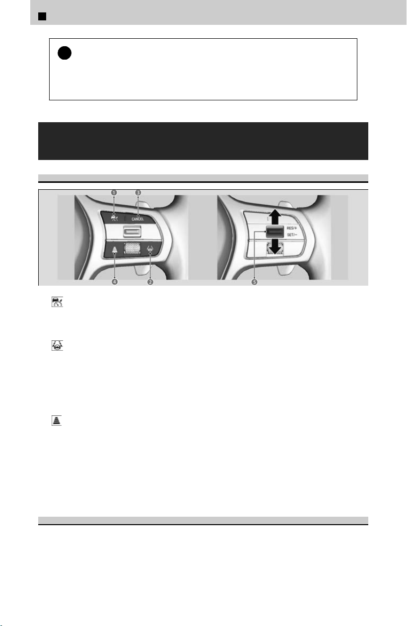
!
To ensure proper operation of the system, observe the following:
Al
l the tires are of the same specified size, type, and brand, and that they are
evenly worn.
Do not modify the suspension.
Device for Operating Each Function and Gauge
Content
Operating Device
a ACC with Low Speed Follow Button
Press to activate standby mode for ACC with Low Speed Follow. Or, press to cancel
the system.
b
LKAS Button
Press to activate standby mode for LKAS and Traffic Jam Assist. Or, press to cancel
these systems.
c CANCEL Button
Press to cancel ACC with Low Speed Follow.
d
Interval Button
Press to change the ACC with Low Speed Follow following-interval.
e RES/+/SET/− Switch
Press the RES/+/SET/− switch up to set or resume the ACC with Low Speed Follow or
increase the vehicle speed. Press the RES/+/ SET/− switch down to set the ACC with
Low Speed Follow or decrease the vehicle speed.
Gauge Content
You can see the current state of each function.
4
Safety Driving Assist System > Honda Sensing®
268
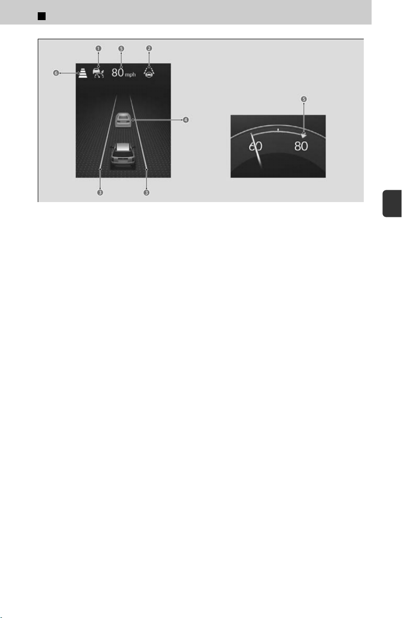
a Indicates that ACC with Low Speed Follow is ready to be activated.
• Green: The system is on.
• White: The system is standby.
• Amber: There is a problem with the system.
b Indicates that LKAS or Traffic Jam Assist is ready to be activated.
• Green: The system is operating.
• White: The system is standby.
• Amber: There is a problem with the system.
c Indicates that LKAS or Traffic Jam Assist is activated and whether or not traffic
lane lines are detected.
• Green lines: The system is operating.
• White lines: Traffic lane lines are detected.
• Amber line: Lane departure is detected.
d Indicates whether or not a vehicle is detected ahead.
• Control target vehicle: White and outlined in green.
• Outside of control target vehicle: Gray.
e Indicates that ACC with Low Speed Follow shows the set vehicle speed.
f Indicates that ACC with Low Speed Follow shows the set vehicle interval.
4
Safety Driving Assist System > Honda Sensing®
269
4
Safety Driving Assist System
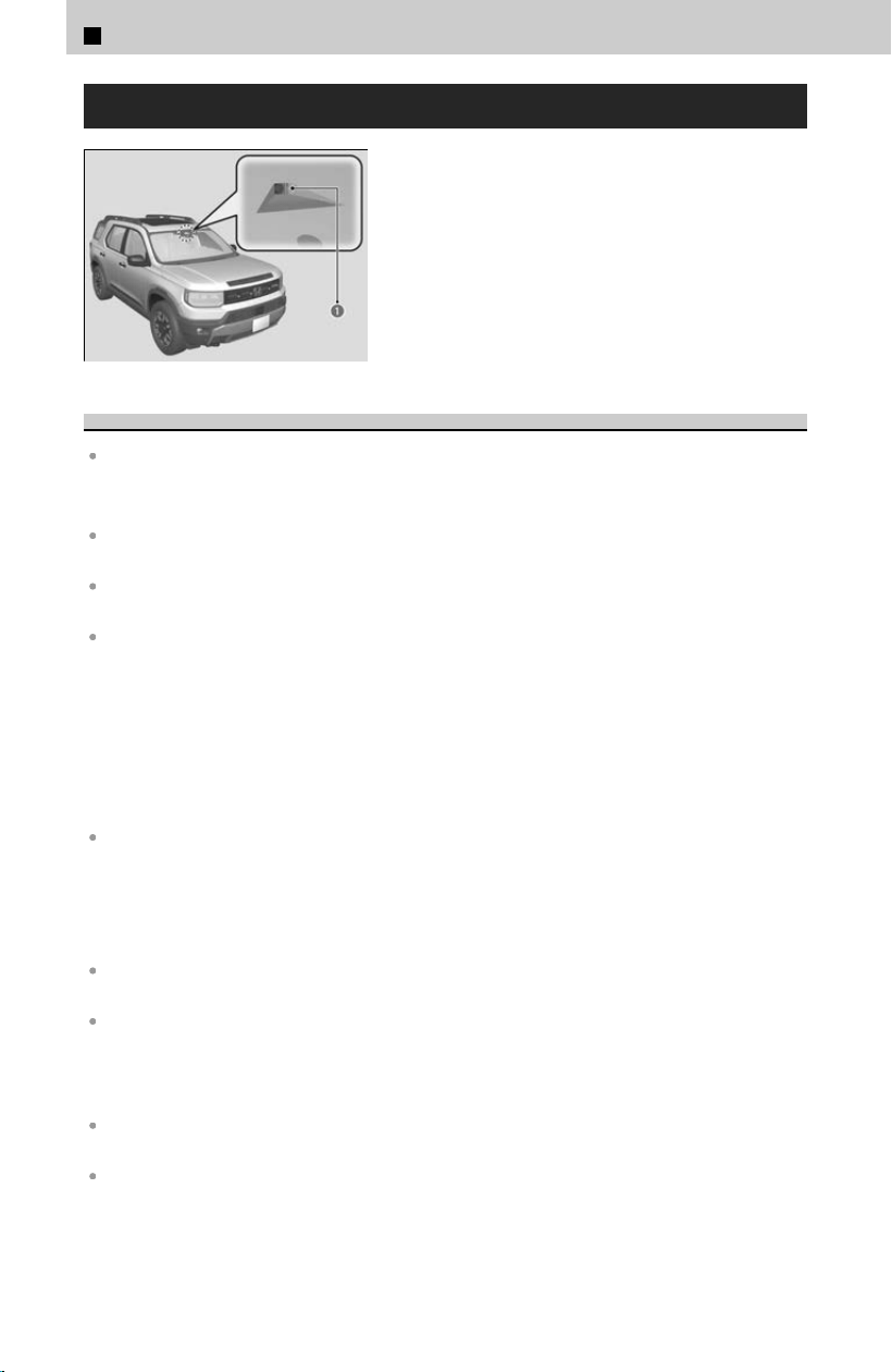
Front Sensor Camera
This front sensor camera (a) is located behind
the rearview mirror.
Handling of the Camera
Avoid high interior temperatures to prevent the camera’s sensing system from shutting off.
≫
It is recommended to find a shady area or face the front of the vehicle away from the sun
when parking.
To avoid concentrating heat on the camera, do not cover the camera when using a reflective
sun shade.
Never apply a film or attach any objects to the windshield, the hood, or the front grille that
could obstruct the camera’s field of vision and cause the system to operate abnormally.
Do not scratch, nick, or cause any other damage to the windshield.
≫
Damage within the camera’s field of vision can cause the system to operate abnormally.
≫
If this occurs, we recommend that you replace the windshield with a genuine Honda
replacement windshield.
≫
After replacing the windshield, have a dealer recalibrate the camera. Proper calibration of
the camera is necessary for the system to operate properly.
≫
Making even minor repairs within the camera’s field of vision or installing an aftermarket
replacement windshield may also cause the system to operate abnormally.
Do not place an object on the top of the instrument panel.
≫
It may reflect onto the windshield and prevent the system from detecting lane lines
properly.
If the Some driv
er assist systems cannot operate: Camera temperature too high
message appears:
Use the climate control system to cool down the interior and, if necessary, also use defroster
mode with the airflow directed toward the camera.
Start driving the vehicle to lower the windshield temperature, which cools down the area
around the camera.
If the Some driv
er assist systems cannot operate: Clean front windshield or poor
viewing condition. message appears:
Park your vehicle in a safe place, and make sure the windshield is clean. Clean the windshield
if it is dirty.
It may also appear in bad weather such as rain, fog, or snow, or when camera visibility is poor
such as at night, in a tunnel, at dawn, or at dusk when the ambient conditions are dark.
4
Safety Driving Assist System > Honda Sensing®
270
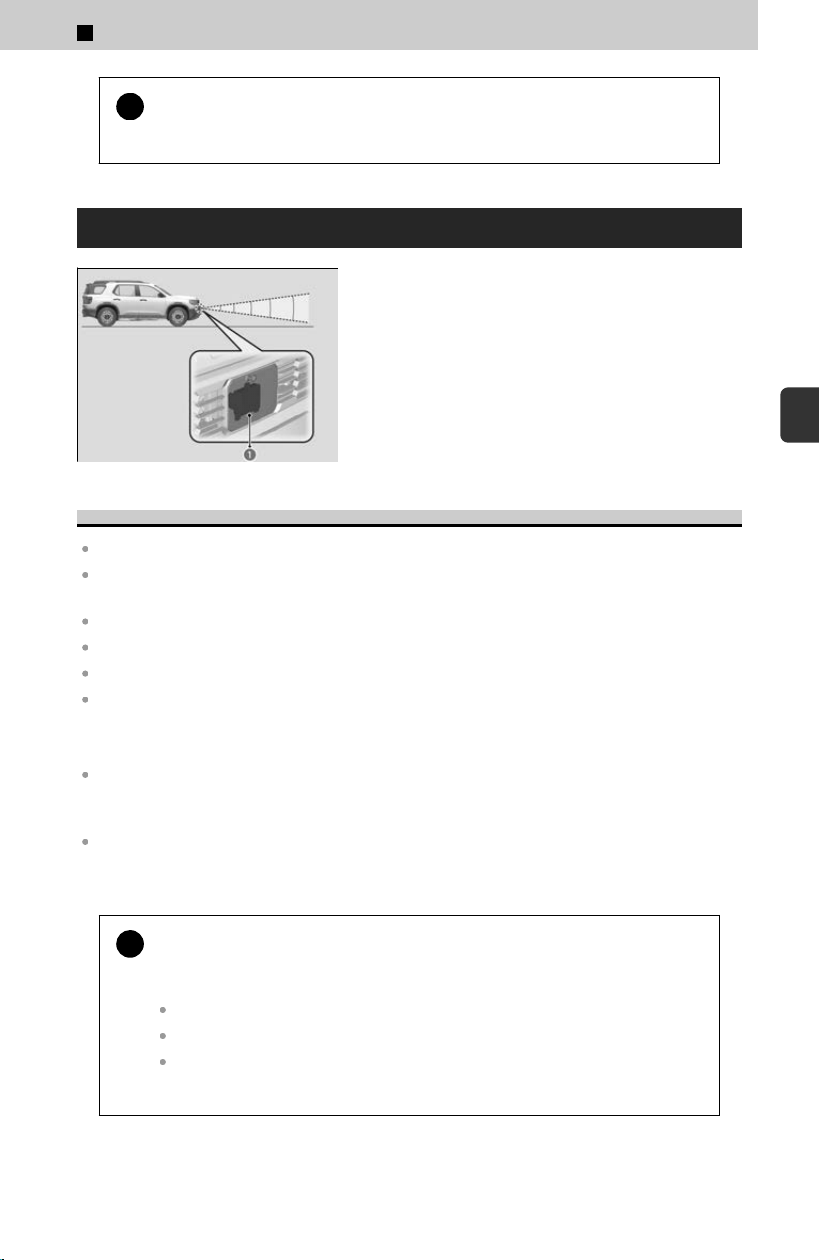
!
If the message does not disappear after you’ve driven for a while, have
y
our vehicle checked by a dealer.
Radar Sensor
The radar sensor (a) is in the front grille.
Handling of the Radar Sensor
Always keep the front grille clean.
Never use chemical solvents or polishing powder for cleaning the front grille. Clean it with
water or a mild detergent.
Do not put any stickers or paint on the front grille.
Do not scratch or damage the front grille.
Do not replace the front grille or bumper.
Do not remove or disassemble the radar sensor.
If the Some driv
er assist systems cannot operate: Clean area shown message
appears:
Stop your vehicle in a safe place and remove the obstacle on the area around the radar sensor
with a soft cloth. The systems will resume once the obstacle has been removed, but
depending on the situation, it may take time for them to do so.
The message may come on temporarily if the radar sensor cannot detect any objects when
passing through an enclosed space such as a tunnel, or driving on an open road without any
structures nearby. It will disappear after driving for a while.
!
If the vehicle is involved in any of the following situations, the radar
sensor may not w
ork properly. Have your vehicle checked by a dealer
if:
Your vehicle is involved in a frontal collision.
Your vehicle drives through deep water or is submerged in deep water.
The area around the sensors strongly strikes a bump, curb, chock, slope, or
embankment that could jar the radar sensor.
4
Safety Driving Assist System > Honda Sensing®
271
4
Safety Driving Assist System
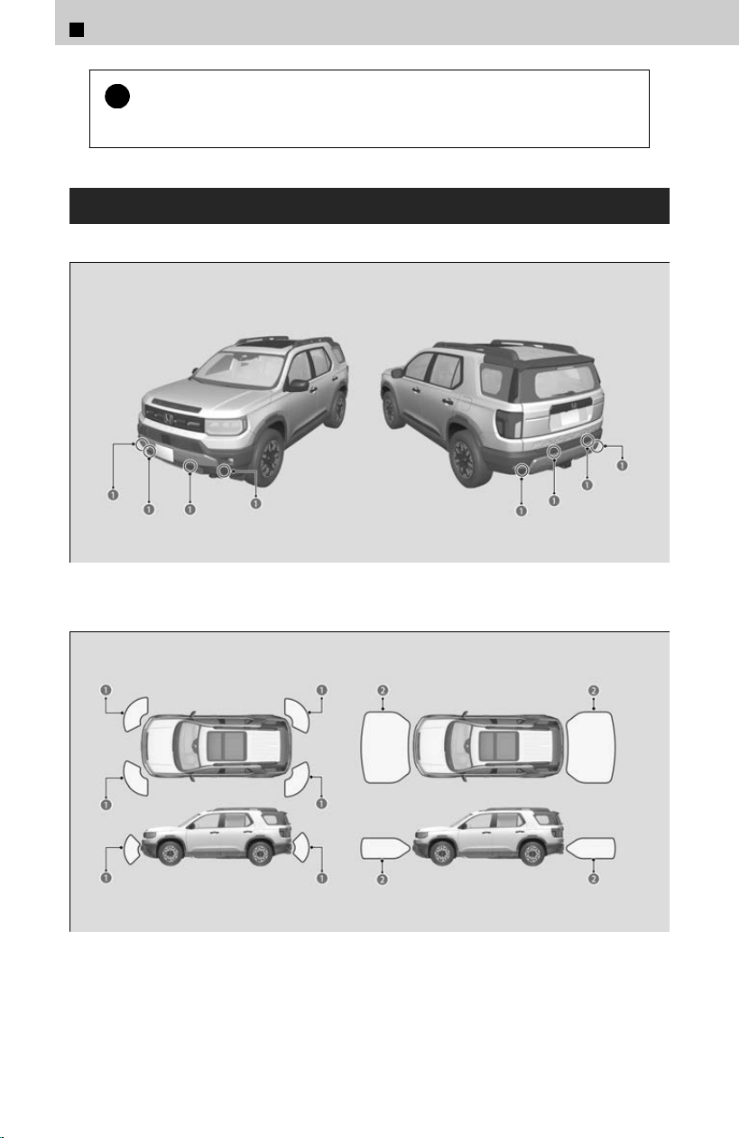
!
If the message does not disappear after the vehicle has been driven
f
or a while, have your vehicle checked by a dealer.
Sonar Sensors
The sonar sensors are situated in the front and rear bumper.
a Sonar Sensors
a Corner Sensor Range
b Center Sensor Range
4
Safety Driving Assist System > Honda Sensing®
272
Handling of the Sonar Sensors
For the sonar sensors to work properly, do not:
Hit the area around the sensors.
Place stickers or other objects on or around the sensors.
Attempt to take apart any sensor.
Put any accessories on or around the sensors.
Consult with a dealer if:
A sensor has been subjected to shock.
Work needs to be done to the area around a sensor.
The front or rear bumper has made contact with a hill, parking block, curb, embankment, etc.
The vehicle has been involved in frontal or rear collision.
The vehicle has been driven through a deep puddle.
If the L
ow speed braking control problem. Parking sensor obstructed. message
appears:
Park your vehicle in a safe place, and make sure the sonar sensors or around the sensors is
clean.
!
If the message does not disappear after the vehicle has been driven
f
or a while, have your vehicle checked by a dealer.
4
Safety Driving Assist System > Honda Sensing®
273
4
Safety Driving Assist System

4
Safety Driving Assist System >
Collision Mitigation Braking System™(CMBS™)
About Collision Mitigation Braking System™
(CMBS™)
The system can assist you when it determines there is a possibility of your vehicle
c
olliding with a vehicle (including motorcycles) ahead from behind, an oncoming
vehicle in front, a pedestrian, or someone riding a bicycle (moving bicycle). The
CMBS™ is designed to alert you when the potential for a collision is determined, as
well as assist in reducing speed, avoiding collisions, and reducing collision severity.
Important Safety Reminder
The CMBS™ is designed to reduce the severity of an unavoidable collision. It does not
prevent collisions nor stop the vehicle automatically. It is still your responsibility to
operate the brake pedal and steering wheel appropriately according to the driving
conditions.
!
Have your vehicle checked by a dealer if you find an
y unusual behavior
of the system (e.g., the warning message appears too frequently).
System Operation
The system starts monitoring the roadway ahead when your vehicle speed is about 3
mph (5 km
/h) or above and will search for a vehicle (including motorcycles),
pedestrian, or moving bicycle in front of you. CMBS™ operates when the system
determines there is a possibility of a collision.
Front Sensor Camera
u
P.270
Radar Sensor
u
P.271
The system has three alert stages for a possible collision.
<Stage one> Situations where there is a risk of a collision with the vehicle ahead
o
f you
The visual alert flashes. If the distance between your vehicle and the vehicle in front
of you continues to decrease, the audible alert sounds in addition to the visual alert
flashing.
<Stage two> Situations where risk of a collision has increased and time to
respond is reduced
Visual and audible alerts come on and the brakes are lightly applied.
274
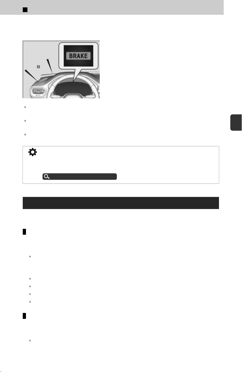
<Stage three> Situations where it is difficult to avoid a collision
Visual and audible alerts come on and the brakes are forcefully applied.
The system provides visual and audible alerts
(a) of a possible collision, and stops if the
collision is avoided.
≫
Take appropriate action to prevent a collision (apply
the brakes, change lanes, etc.)
Depending on circumstances, the CMBS™ may not go through all of the stages before initiating
the last stage.
After CMBS™ is activated and your vehicle stops or decelerates, CMBS™ will be deactivated
based on the system’s judgment.
The CMBS™ may be canceled when you operate the steering wheel, brake, or accelerator
pedal to avoid a collision.
You can change the distance (Long/Normal/Short) between vehicles at which the
system’s earliest collision alert will come on. When in Long, visual and audible alerts
come on at a longer distance from a vehicle ahead than in Normal setting, and in
Short, at a shorter distance than in Normal.
Customized Features
u
P.239
Operating Conditions
The conditions and targets of operation for CMBS™ are as follows:
When going straight
When your vehicle speed is about 3 mph (5 km/h) or more, and the speed
diff
erence with the target is about 3 mph (5 km/h) or more:
The vehicle (including motorcycles) ahead of you
When your vehicle speed is about 3-62 mph (5-100 km/h), and the speed
diff
erence with the target is about 3 mph (5 km/h) or more:
Stopped vehicle (including motorcycles)
Oncoming vehicle
Pedestrian
Moving bicycle
When turning left (only when there is a risk of a head-on collision)
When your vehicle speed is about 3-18 mph (5-30 km/h), and the speed difference
with the tar
get is about 3 mph (5 km/h) or more:
Oncoming vehicle
*1
4
Safety Driving Assist System > Collision Mitigation Braking System™(CMBS™)
275
4
Safety Driving Assist System

*1: Activates only when turning into the oncoming lane.
When the CMBS™ is activated, it will continue to operate even if the accelerator pedal is
partially depressed. However, it will be canceled if the accelerator pedal is fully depressed.
The camera in the CMBS™ is also designed to detect pedestrians. However, this pedestrian
detection feature may not activate or may not detect a pedestrian in front of your vehicle
under certain conditions. Refer to the ones indicating the pedestrian detection limitations
from the list.
CMBS™ Limitations
u
P.276
Automatic Shut Off
The CMBS™ may automatically shut itself off and the safety support indicator (amber)
c
omes on and stays on when:
You drive off-road or on a mountain road, or curved and winding road for an extended period.
Driving in bad weather (rain, fog, snow, etc.).
Driving with the parking brake applied.
The radar sensor temperature gets too high.
The front of the camera or a radar sensor on the front grille is obstructed by dirt, fog, rain,
mud, wet snow, accessories, decals, stickers, film, etc.
An abnormal tire condition is detected (incorrect tire size, flat tire, etc.).
Once the conditions that caused the CMBS™ to shut off improve or are addressed
(e
.g., cleaning), the system comes back on.
CMBS™ On and Off
You can turn the system on and off using the driver information interface.
Switching the Display
u
P.334
Safety Support
u
P.338
The CMBS™ is turned on every time you start the engine, even if you turned it off the last time
you drove the vehicle.
You cannot turn the CMBS™ off while driving.
CMBS™ Limitations
In the following situations, the radar sensor or camera may be unable to correctly
identif
y detectable targets or road conditions, potentially causing the CMBS™ to
operate improperly.
Environmental conditions
Driving in bad weather (rain, fog, snow, etc.).
Sudden changes between light and dark, such as an entrance or exit of a tunnel.
4
Safety Driving Assist System > Collision Mitigation Braking System™(CMBS™)
276

There is little contrast between detectable targets and the background.
Driving into low sunlight (e.g., at dawn or dusk).
Strong light is reflected onto a detectable target or roadway.
Driving in the shadows of trees, buildings, etc.
Reflections on the interior of the windshield.
Driving at night or in a dark place such as a tunnel (due to low-light conditions, detectable
target may not be illuminated).
When nearby radio wave emitting devices such as other automotive radar sensors.
Roadway conditions
Driving on a snowy or wet roadway (obscured lane marking, vehicle tracks, reflected lights,
road spray, high contrast).
Driving on curvy, winding, or undulating roads.
The road is hilly or the vehicle is approaching the crest of a hill.
Your vehicle is strongly shaken on uneven road surfaces.
Driving through an area where there are objects that strongly reflect radio waves onto
vehicles, pedestrians, or moving bicycles.
Vehicle conditions
Driving at night or in a dark place (e.g., a tunnel) with the headlights off.
The front of the camera is obstructed by dirt, fog, rain, mud, wet snow, accessories, decals,
stickers, film, etc.
The area around the front grille is obstructed by dirt, rain, mud, wet snow, accessories,
decals, stickers, film, etc.
There is residue on the windshield from the windshield wipers.
The inside of the windshield is fogged.
When lighting is weak due to dirt covering the headlight lenses, or there is poor visibility in a
dark place due to the headlights being improperly adjusted.
An abnormal tire or wheel condition (incorrect sizes, varied sizes or construction,
improperly inflated, compact spare tire, etc.).
The vehicle is tilted due to heavy load in the cargo area or rear seats.
The suspension has been modified.
Driving with the parking brake applied.
Tire chains are installed.
*
The vehicle is towing a trailer.
Examples of limitations on the correct detection of the radar and
camera due to the condition of detectable targets
The distance between your vehicle and the detectable target is too short.
The detectable target suddenly cuts in front of or jumps out in front of you.
The bicycle is stopped.
The oncoming vehicle or vehicle ahead of you is sideways or facing diagonally.
*: Not available on all models
4
Safety Driving Assist System > Collision Mitigation Braking System™(CMBS™)
277
4
Safety Driving Assist System

When the detectable target blends in with the background, preventing the system from
recognizing it.
When several pedestrians are moving ahead of you in a group.
When several bicycles are moving ahead of you in a group.
When a pedestrian or moving bicycle crosses the road too quickly.
A pedestrian or moving bicycle approaches from the opposite direction.
The headlights of the vehicle ahead of you or oncoming vehicle are lit on one side or not lit
on either side in a dark place.
When part of a pedestrian (heads, limbs, etc.) is hidden by a carried object.
When a pedestrian is bent over or squatting, when their hands are raised, or when they are
running.
When the pedestrian is shorter than about 3.3 feet (1 meter) or taller than about 6.6 feet (2
meters) in height.
When the pedestrian is pushing a stroller or bicycle.
Examples of other limitations on detection or system operation
When the vehicle ahead of you is a small motorcycle, motorcycle with a sidecar, wheelchair,
or other specially shaped vehicle.
When a vehicle is lower in the rear than the front such as trucks that are not carrying a
cargo, or a narrow vehicle.
When the detectable target is not in front of the vehicle.
The speed difference between your vehicle and the detectable target is significantly large.
The speed difference between your vehicle and the detectable target is too small and the
distance between your vehicle and them is too short.
When a vehicle (including motorcycles) or moving bicycle in front of you slows suddenly.
When the driver operates the brake pedal and steering wheel to avoid a collision.
When you approach the detectable target while accelerating rapidly or operating the
steering wheel (except when turning left at an intersection, etc.)
*1
When the moving bicycle is a child-sized bicycle, folding bicycle, three-wheeler or other
bicycle with small tires, or a long bicycle like a tandem bicycle.
When the front of the camera cannot correctly identify the shape of the detectable target.
When the minimum ground clearance of a vehicle that is ahead of you is extremely high.
*1: When there is a possibility of a frontal collision with the oncoming vehicle while turning left,
the CMBS™ is activ
ated. However, it may not be activated if you suddenly turn the steering
wheel.
With little chance of a collision
Even if there is little chance of a collision, the CMBS™ may activate in the following
situations
, such as when the system determines that there is a possibility of
collision with a detectable target.
4
Safety Driving Assist System > Collision Mitigation Braking System™(CMBS™)
278
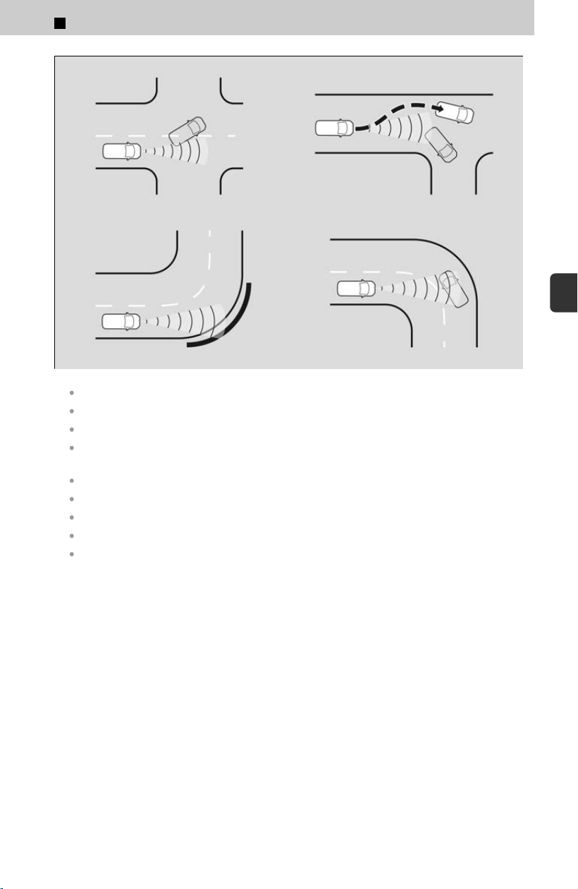
When your vehicle approaches a vehicle ahead that is turning left or right.
Your vehicle approaches another vehicle ahead of you and you change lanes to pass.
When there are detectable targets or any structures around the curved road.
When driving through curves, your vehicle comes to a point where the oncoming vehicle is
left in front of you.
When your vehicle approaches a detectable target.
When detectable targets are passing in front of you.
When you drive under a low structure or through a narrow gate at high speed.
When approaching stationary vehicles or walls, such as when parking.
Roadway objects or structures such as guard rails, poles, trees, parked vehicles, buildings,
walls, etc., or road markings and road lines are misinterpreted as detectable targets.
4
Safety Driving Assist System > Collision Mitigation Braking System™(CMBS™)
279
4
Safety Driving Assist System

4
Safety Driving Assist System >
Low Speed Braking Control
About Low Speed Braking Control
Using sonar sensors, this system can detect if there is danger of a potential collision
with a w
all or other obstacle during normal driving or when the accelerator pedal is
depressed with too much force. The system then assists in avoiding collisions and
reducing damage from impact through assistive braking and/or assistive driving
power suppression.
Sonar Sensors
u
P.272
If the Low Speed Braking Control activates in a situation where you do not want automatic
brake application (such as when the vehicle is between two railroad crossing gates), simply
press the brake pedal to deactivate the system and then continue to drive as intended.
The vehicle will release the brake and start moving a few seconds after the system is
activated. To keep the vehicle stopped, keep the brake pedal depressed or put the
transmission into P .
In order to prevent the system from activating when not needed, always turn it off during
vehicle maintenance; when loading on ships, trucks, and so on; when using a chassis
dynamometer or free rollers for inspection; or when washing the car in conveyor type car
wash machine.
After Low Speed Braking Control has activated once, it will not activate again for the same
obstacle. It can be activated again after driving for a certain distance after last activation.
Low Speed Braking Control activates separately when moving forward and reversing. (For
example, if it activates when moving forward, it can be activated again immediately if
reversing.)
When the Drive Mode is changed to TOW mode, the Low Speed Braking Control System will
not work when reversing.
Drive Mode System
u
P.159
When the Drive Mode is changed to TRAIL mode, the Low Speed Braking Control System will
not work.
Drive Mode System
u
P.159
3 WARNING
The Low Speed Braking Control System cannot avoid all collisions and may
not r
educe damage in each situation where the accelerator is mistakenly or
aggressively pressed. Overreliance on the system may result in a collision
with serious injury or death. Always check your surroundings, your shift
position, and your pedal use. Driver remains responsible for safely
operating the vehicle.
280
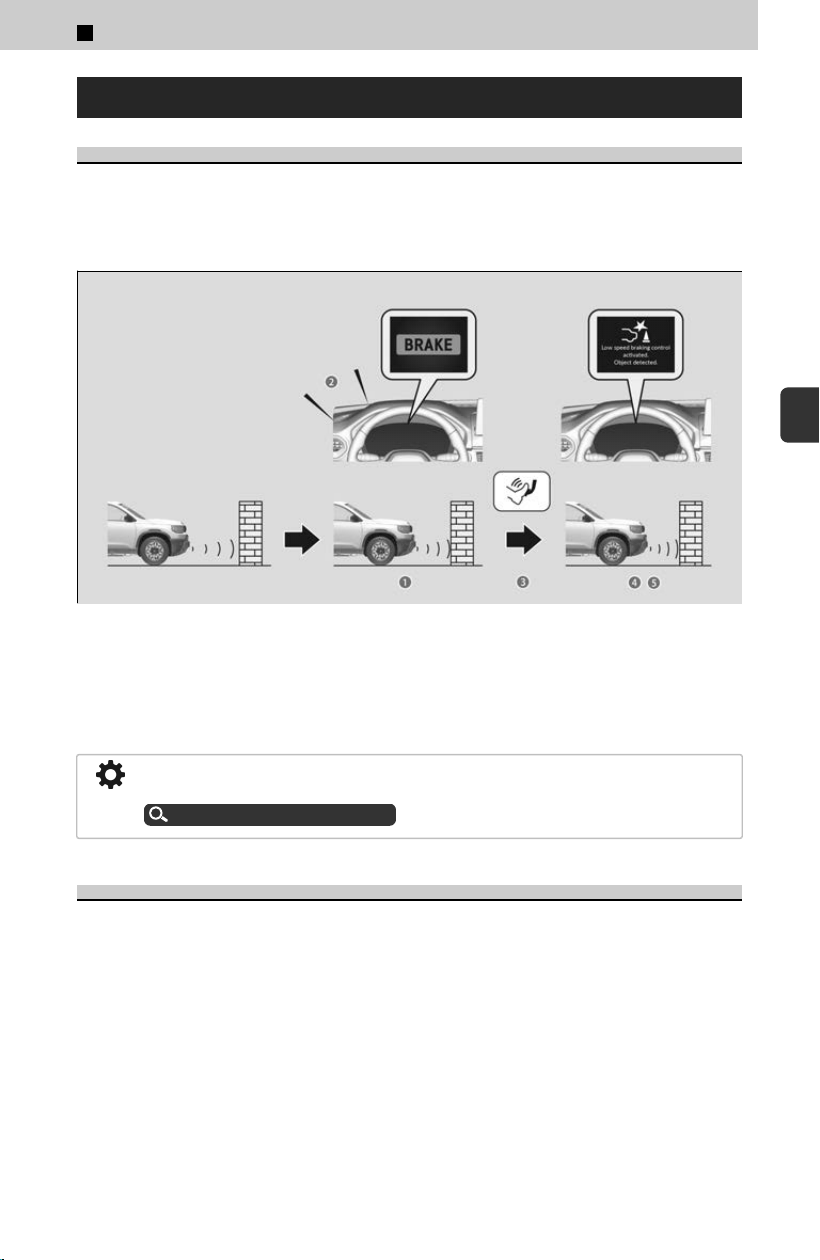
How the System Works
Assistive Braking
Assistive braking provides a visual and audible alert when the vehicle is moving
betw
een approximately 1 and 6 mph (2 and 10 km/h) and there is the possibility of a
collision with a detected wall or other obstacles, as well as providing assistance with
braking.
a The vehicle applies brake
b Audible Alert
c Driver depresses brake pedal
d Stop
e Release brake after maintaining stationary position
If only the rear parking sensors are turned off, the assistive braking will not work
when reversing.
Customized Features
u
P.239
Assistive Driving Power Suppression
When the vehicle is stopped or moving at less than 6 mph (10 km/h) and there is an
obs
tacle such as a wall detected near the front or back of the vehicle, if the
accelerator pedal is depressed more than necessary, the system will inform you with
a visual and audible alert. At the same time, the system will prevent sudden forward
or backwards movement by limiting the output of the engine, then assistive braking
will activate when you get closer to the obstacle.
4
Safety Driving Assist System > Low Speed Braking Control
281
4
Safety Driving Assist System
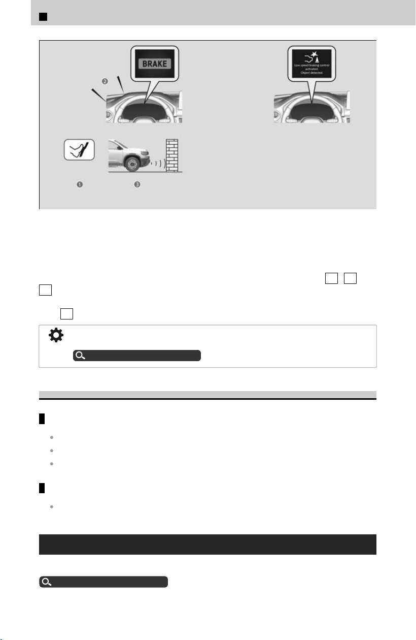
a Accidental depression of the accelerator
b Audible Alert
c Limiting the output of the engine
Assistive driving power suppression will not activate in the following situations.
When moving forward: When on a s
teep slope or the shift position is in P , R , or
N .
When reversing: When on a steep slope or the shift position is in a position other
than R .
If only the rear sensors are turned off, the assistive driving power suppression will not
work when reversing.
Customized Features
u
P.239
Conditions for Cancellation
Conditions for assistive driving power suppression:
When the accelerator is no longer depressed.
When the accelerator is depressed for approximately four seconds.
When the brake pedal is depressed.
Conditions for assistive braking cancellation:
A certain amount of time has passed since activation.
Low Speed Braking Control System ON/OFF
You can turn the system on and off using the driver information interface.
Switching the Display
u
P.334
4
Safety Driving Assist System > Low Speed Braking Control
282

Safety Support
u
P.338
The system is turned on every time you start the engine, even if you turned it off the last time
you drove the vehicle.
You cannot turn the Low Speed Braking Control on while the Drive Mode is in TRAIL mode.
Drive Mode System
u
P.159
The Low Speed Braking Control system may temporarily turn off after reconnecting the 12-
volt battery. The system will automatically turn ON after the vehicle has been moving at over
12 mph (20 km/h) for some time.
Low Speed Braking Control System Limitations
The vehicle is tilted due to heavy load in the cargo area or rear seats.
Examples of obstacles the sonar sensor cannot detect
Obstacles that do not reflect sound waves well, such as people, snow, cloth, sponges, etc.
Thin obstacles such as fences, bicycles, sign posts, etc.
Short or small obstacles.
Obstacles immediately in front of the bumper.
Moving objects or obstacles that suddenly enter the road.
Obstacles that are not perpendicular to the ground.
Examples of situations where the sonar sensors cannot detect
obstacles
The sonar sensors are dirty (covered by snow, water, mud, etc.).
The vehicle is too hot or cold.
The steering wheel is turned sharply when approaching the obstacle at an angle.
Examples of other cases where the system may not work correctly
The vehicle is tilted due to heavy load in the cargo area or rear seats.
Bad weather conditions such as heavy rain, fog, snow, sandstorms, etc.
The ambient temperature/humidity is too high or low.
When going down a very steep slope.
When driving off-road such as on dirt, grass, or rock.
When close to other vehicles with sonar sensors or other objects that emit ultrasonic
waves.
An abnormal tire or wheel condition (incorrect sizes, varied sizes or construction,
improperly inflated, compact spare tire, etc.).
The suspension has been modified.
Situations where the system may activate even without risk of a
collision
When passing through short or narrow gates.
When driving on uneven surfaces, grassy areas, or places with steps.
4
Safety Driving Assist System > Low Speed Braking Control
283
4
Safety Driving Assist System

When a sloped pillar or wall is protruding from a high position.
When there are obstacles next to the road.
When driving toward flags, curtains, tree branches, railroad crossing bars, etc.
When driving on flooded roads.
!
Do not put any accessories on or around the sensors.
If y
ou put any accessories (such as a towing hitch or bicycle rack) on or around
the rear sensors, the system may activate if it detects these accessories as an
obstacle. In this case, turn off the rear sensor.
Customized Features
u
P.239
4
Safety Driving Assist System > Low Speed Braking Control
284
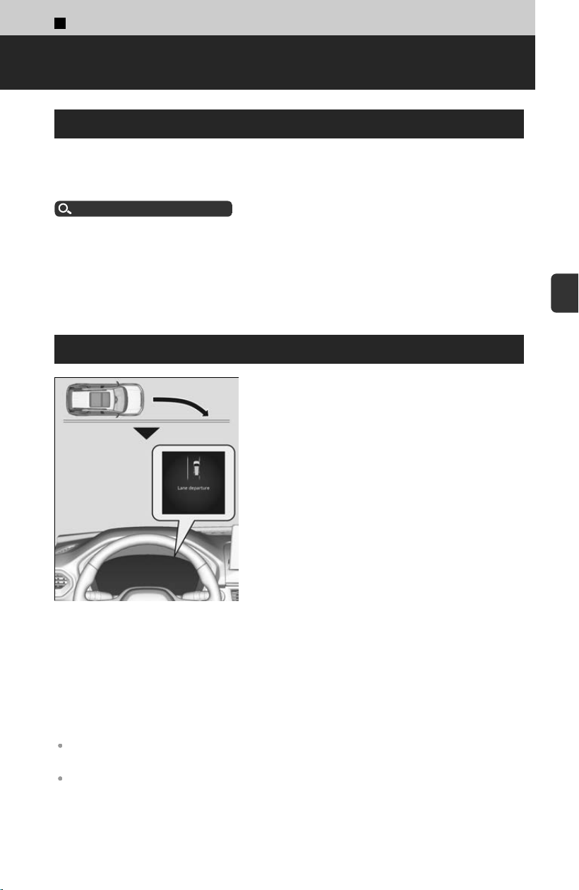
4
Safety Driving Assist System >
Road Departure Mitigation System
About Road Departure Mitigation System
Alerts and helps assist you when the system detects a possibility of your vehicle
cr
ossing over detected lane markings, or approaching the outer edge of the pavement
(into grass or gravel road shoulder) or a detected oncoming vehicle.
Front Sensor Camera
u
P.270
Important Safety Reminder
Like all assistance systems, the Road Departure Mitigation system has limitations.
Overreliance on the Road Departure Mitigation system may result in a collision. It is
al
ways your responsibility to keep the vehicle within your driving lane.
System Operation
The camera monitors left and right lane markings
in white (yellow), the outer edge of the pavement
(bordered by grass or gravel road shoulder), or a
detected oncoming vehicle. If your vehicle
approaches any detected lane markings, the
outer edge of the pavement (bordered by grass or
gravel road shoulder), or a detected oncoming
vehicle when the turn signals have not been
engaged, the system activates.
≫
If the system cannot detect lane markings (in white
or yellow), no assistance will be provided to avoid
approaching oncoming vehicles.
In addition to a visual alert, the system assists with steering and alerts you with rapid
s
teering wheel vibrations to help you remain within the detected lane.
The system cancels assisting operations when you turn the steering wheel to avoid
crossing over detected lane markings or approaching the outer edge of the pavement
(into grass or gravel road shoulder) or an oncoming vehicle.
If the system operates several times without detecting driver response, the system
beeps to alert you.
The Road Departure Mitigation system may automatically shut off and the safety support
indicator (amber) comes and stays on.
There are times when you may not notice the Road Departure Mitigation system functions due
to your operation of the vehicle, or road surface conditions.
285
4
Safety Driving Assist System
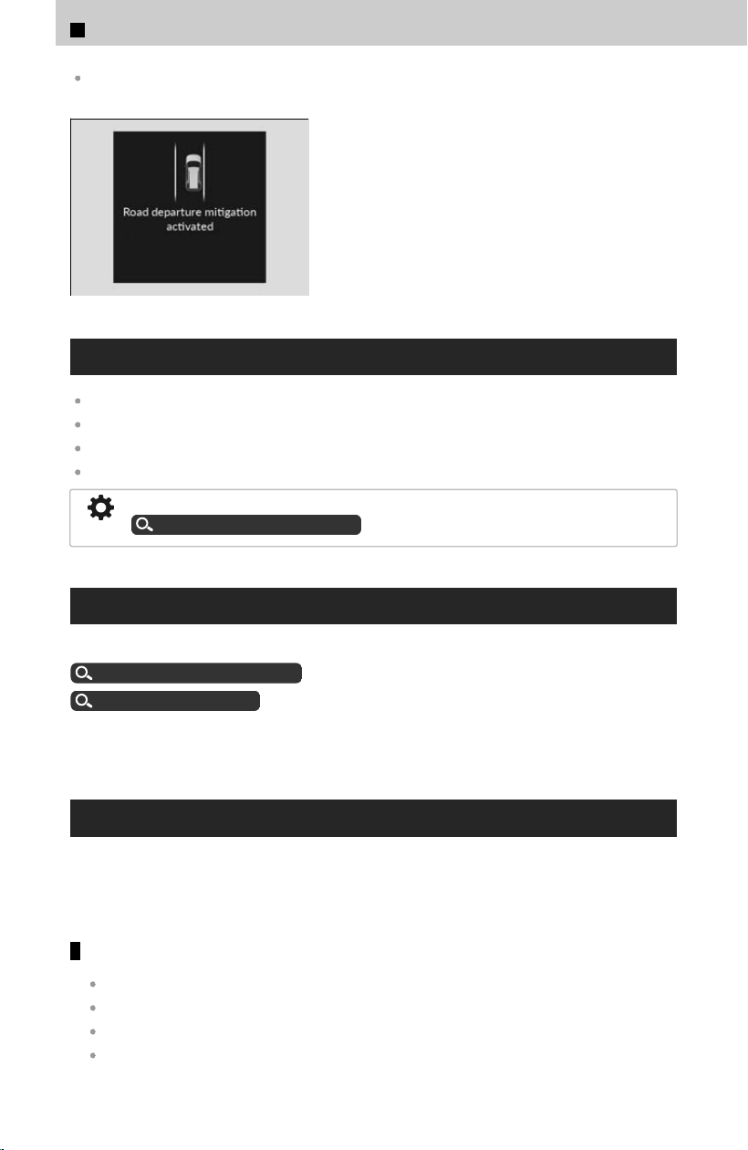
The Road Departure Mitigation system function can be impacted when the vehicle is driven on
the inside edge of a curve, outside of a lane, or in a narrow lane.
If Lane Keeping Assist System (LKAS) is off, the
message may appear if the system has
determined that there is a possibility of your
vehicle crossing over detected lane markings, the
outer edge of the pavement (into a grass or gravel
road shoulder) or oncoming vehicle.
Operating Conditions
The vehicle is traveling between about 45 and 90 mph (72 and 145 km/h).
The vehicle is on a straight or slightly curved road.
The turn signals are off.
The system determines that the driver is not actively accelerating, braking, or steering.
You can set the timing for Road Departure Mitigation system activation.
Customized Features
u
P.239
Road Departure Mitigation System On and Off
You can turn the system on and off using the driver information interface.
Switching the Display
u
P.334
Safety Support
u
P.338
The Road Departure Mitigation system is in the previously selected on or off setting
each time y
ou start the engine.
Road Departure Mitigation System Limitations
The system may not properly detect lane markings (in white or yellow), the outer
edg
e of the pavement (into grass or gravel road shoulder), or an oncoming vehicle
under certain conditions. Some examples of these conditions are listed below.
Environmental conditions
There is little contrast between lane lines and the roadway surface.
Driving in bad weather (rain, fog, snow, etc.).
Driving on a snowy or wet roadway.
Driving into low sunlight (e.g., at dawn or dusk).
4
Safety Driving Assist System > Road Departure Mitigation System
286

Shadows of adjacent objects (trees, buildings, guard rails, vehicles, etc.) are parallel to
white (or yellow) lines.
Sudden changes between light and dark, such as the entrance or exit of a tunnel or the
shadows of trees, buildings, etc.
Strong light is reflected onto the roadway.
Driving at night or in a dark place such as a tunnel (due to low-light conditions, lane lines,
the road surface, or oncoming vehicles may not be illuminated).
The distance between your vehicle and the vehicle ahead of you is too short, and lane lines
and the road surface are not visible.
The outer edge of the road is bordered by objects, materials, etc. other than grass or gravel.
Roadway conditions
Driving on a road with temporary lane markings.
Faint, multiple, or varied lane markings are visible on the roadway due to road repairs or old
lane markings.
The roadway has merging, split, or crossing lines, such as at an intersection or crosswalk.
The lane markings are extremely narrow, wide, or changing.
Part of the lane markings are hidden by an object, such as a vehicle.
The road is hilly or the vehicle is approaching the crest of a hill.
Your vehicle is strongly shaken on uneven road surfaces.
When objects on the road (curb, guard rail, pylons, etc.) are recognized as white (or yellow)
lines.
Driving on rough or unpaved roads, or over bumpy surfaces.
Driving on roads with double lane lines.
Driving on snowy or slippery roads.
Passing through an exit or an intersection.
The pavement is only partially visible due to snow or puddles on the road.
Driving on unpaved or rutted roads.
White (or yellow) lines are not recognized correctly due to road conditions such as curves,
twists, or hills.
Vehicle conditions
When lighting is weak due to dirt covering the headlight lenses, or there is poor visibility in a
dark place due to the headlights being improperly adjusted.
The front of the camera is covered by dirt, fog, rain, mud, wet snow, accessories, stickers, or
film on the windshield.
Driving at night or in a dark place (e.g., a tunnel) with the headlights off.
When the driver operates the brake pedal and steering wheel.
There is residue on the windshield from the windshield wipers.
The inside of the windshield is fogged.
An abnormal tire or wheel condition (incorrect sizes, varied sizes or construction,
improperly inflated, compact spare tire, etc.).
The vehicle is tilted due to heavy load in the cargo area or rear seats.
The suspension has been modified.
4
Safety Driving Assist System > Road Departure Mitigation System
287
4
Safety Driving Assist System

Tire chains
*
are installed.
The vehicle is towing a trailer.
Examples of limitations on detection due to the condition of oncoming
vehicles
The oncoming vehicle or vehicle ahead of you is sideways.
The oncoming vehicle jumps out in front of you.
When the oncoming vehicle blends in with the background, preventing the system from
recognizing it.
The headlights of an oncoming vehicle are lit on one side or not lit on either side in a dark
place.
The distance between your vehicle and the oncoming vehicle is too short.
Part of the oncoming vehicle is not visible due to the vehicle ahead of you.
There are multiple oncoming lanes or turning lanes.
The vehicle in the adjacent lane is parked or moving at an extremely slow speed.
When the oncoming vehicle is specially-shaped.
When the camera cannot correctly identify the shape of the oncoming vehicle.
With little chance of a collision
The Road Departure Mitigation system may activate in the below conditions.
When driving through curves, your vehicle comes to a point where an oncoming vehicle is
right in front of you.
*: Not available on all models
4
Safety Driving Assist System > Road Departure Mitigation System
288

4
Safety Driving Assist System >
Adaptive Cruise Control (ACC) with Low Speed Follow
About ACC with Low Speed Follow
Helps maintain a constant vehicle speed and a set following-interval behind a vehicle
det
ected ahead of yours and, if the detected vehicle comes to a stop, can decelerate
and stop your vehicle, without you having to keep your foot on the brake or the
accelerator.
Front Sensor Camera
u
P.270
Radar Sensor
u
P.271
Important Reminder
As with any system, there are limits to ACC with Low Speed Follow. Use the brake
pedal whene
ver necessary, and always keep a safe interval between your vehicle and
other vehicles.
3 WARNING
Improper use of ACC with Low Speed Follow can lead to a crash.
Use A
CC with Low Speed Follow only when driving on expressways or
freeways and in good road and weather conditions.
ACC with Low Speed Follow has limited braking capability and may not stop
your vehicle in time to avoid a collision with a vehicle that quickly stops in
front of you.
Always be prepared to apply the brake pedal if the conditions require.
Exiting a vehicle that has been stopped while the ACC with Low Speed
Follow system is operating can result in the vehicle moving without
operator control. A vehicle that moves without operator control can cause a
crash, resulting in serious injury or death.
Never exit a vehicle when the vehicle is stopped by ACC with Low Speed
Follow.
289
4
Safety Driving Assist System
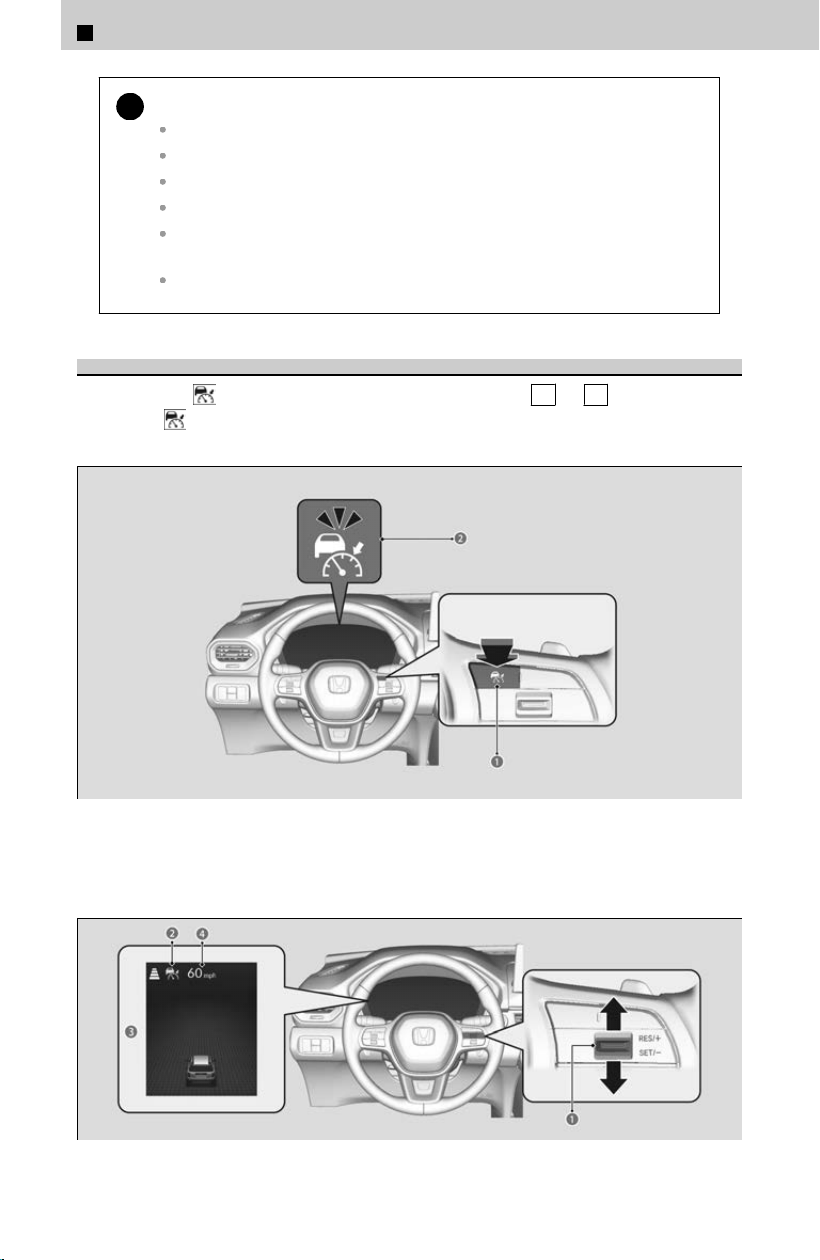
!
Do not use ACC with Low Speed Follow under the following conditions:
On roads with frequent lane change or continuous stop and go traffic.
On roads with sharp turns.
On roads with undulating slopes.
On roads with steep uphill or steep downhill slopes.
On roads with toll collection facilities or other objects between lanes of
traffic, or in parking areas, or facilities with drive through access.
On roads with slippery or icy surfaces.
How to Activate ACC with Low Speed Follow
[1] Press the
button (a) while the shift position is in D or S .
≫
The indicator (white) (b) comes on.
[2] Press the RES/+/SET/− switch (a) up or down.
≫
The system will start operating at the set speed.
≫
The icons and set speed will be displayed on the gauge.
4
Safety Driving Assist System > Adaptive Cruise Control (ACC) with Low Speed Follow
290
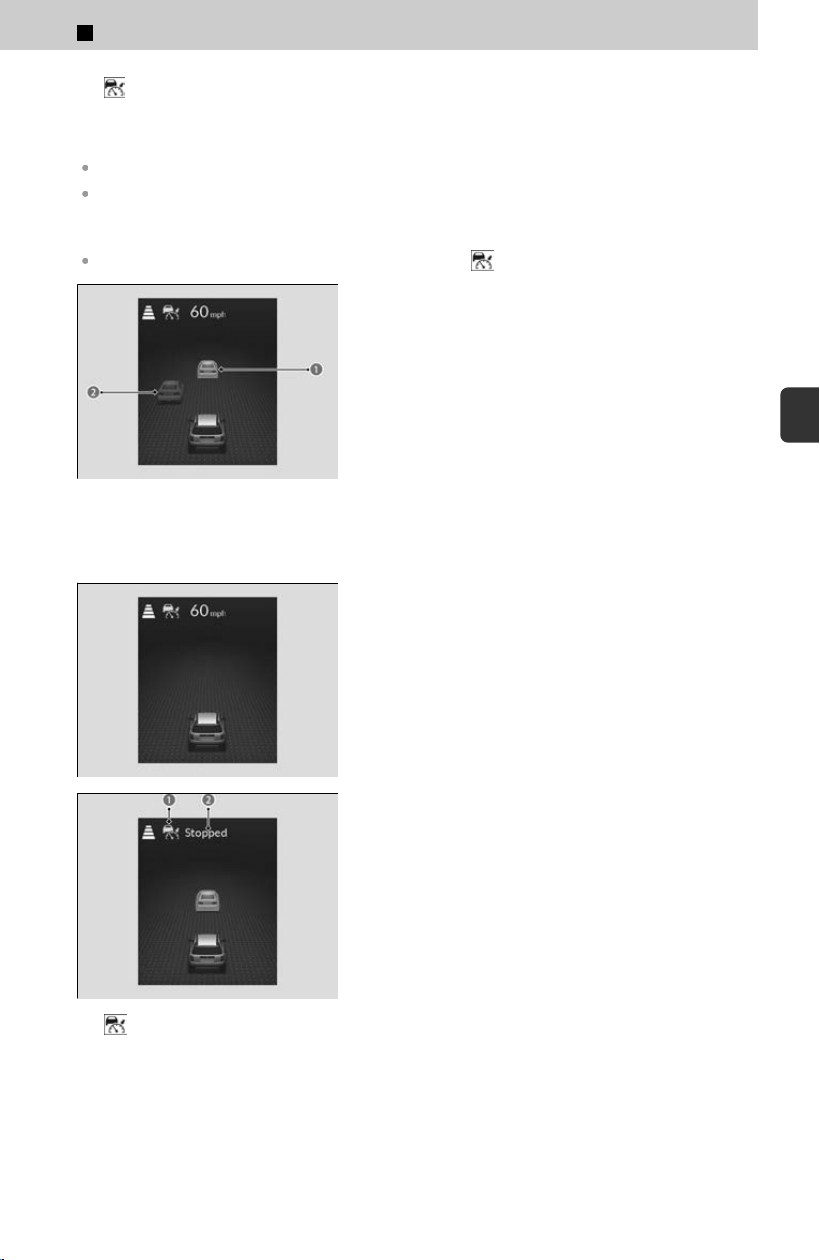
b Indicator (Green)
c On when ACC with Low Speed Follow begins
d Set Vehicle Speed (White)
ACC with Low Speed Follow does not operate while the brake pedal is depressed.
When driving at 20 mph (30 km/h) or less, the vehicle speed is set to 20 mph (30 km/h).
If your vehicle is stationary, you can set the vehicle speed even with the brake pedal
depressed.
When not using ACC with Low Speed Follow, press the button to turn off the system.
a Control target vehicle
b Outside of control target
vehicle
If a vehicle ahead enters the detectable range,
ic
on (a) appears, and the system adjusts your
vehicle’s speed within the set range in order to
keep the vehicle’s set following-interval.
If there is no vehicle ahead, your vehicle
maintains the set speed. If a vehicle ahead leaves
due to actions such as changing lanes, the system
will slowly accelerate to the set speed and then
maintain it.
a Indicator (green)
Your vehicle also stops automatically. The
mes
sage (b) appears on the gauge.
When the vehicle ahead of you starts again, if you
pr
ess the RES/+/SET/− switch up or down, or
depress the accelerator pedal, ACC with Low
Speed Follow operates again within the
previously set speed.
≫
When your vehicle stops automatically because a
vehicle detected ahead of you has stopped, the
interval between the two vehicles will vary based on
the interval setting.
4
Safety Driving Assist System > Adaptive Cruise Control (ACC) with Low Speed Follow
291
4
Safety Driving Assist System
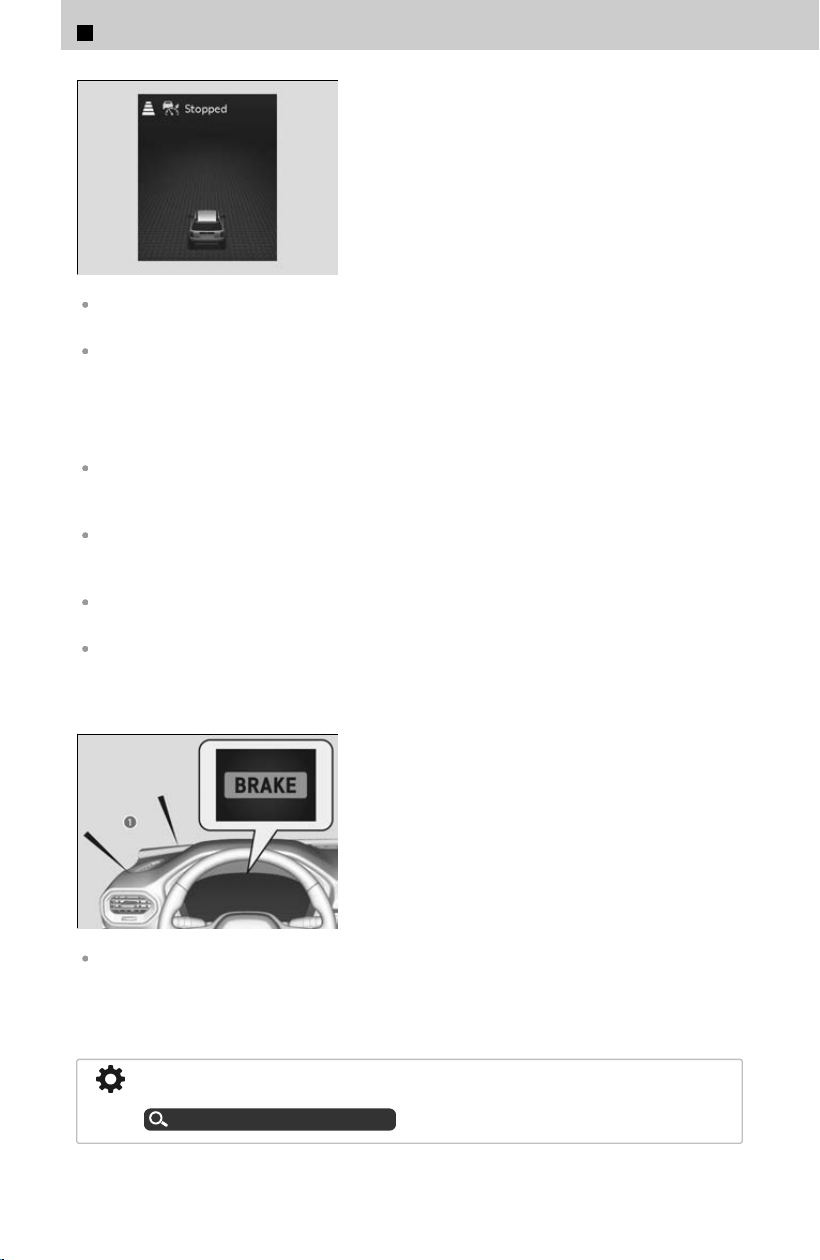
If no vehicle is ahead of you before you resume
driving, depress the accelerator pedal and ACC
with Low Speed Follow will operate again within
the prior set speed.
When a vehicle whose speed is slower than your set speed comes in or cuts in front of you
and is detected by the camera, your vehicle starts to slow down.
Even if the interval between your vehicle and the vehicle detected ahead is short, ACC with
Low Speed Follow may start accelerating your vehicle under the following circumstances:
≫
The vehicle ahead of you is going at almost the same speed as, or faster than, your vehicle.
≫
A vehicle that cuts in front of you is going faster than your vehicle, gradually increasing the
interval between the vehicles.
While driving down steep hills, ACC with Low Speed Follow brakes to inhibit excessive
acceleration for maintaining the set speed. However, the vehicle speed may become faster
than the set speed.
When the vehicle ahead of you moves away, such as when entering an interchange or rest
area, ACC with Low Speed Follow may continue to maintain the set following-interval for a
short time.
When ACC with Low Speed Follow slows your vehicle by applying the brakes, your vehicle’s
brake lights will illuminate.
ACC with Low Speed Follow may temporarily control the interval between your vehicle and the
vehicle in adjacent lane or surroundings of your vehicle depending on the road conditions
(e.g., curves) or vehicle conditions (e.g., operating the steering wheel or the vehicle location in
the lane).
If the vehicle ahead of you slows down abruptly,
or if another vehicle cuts in front of you, the
beeper sounds (a) and a message appears.
≫
Depress the brake pedal, and keep an appropriate
interval from the vehicle ahead.
You can temporarily increase the vehicle speed. In this case, there is no audible or visual alert
even if a vehicle is in the ACC with Low Speed Follow range. ACC with Low Speed Follow stays
on unless you cancel it. Once you release the accelerator pedal, the system resumes an
appropriate speed for keeping the following-interval while a vehicle ahead is within the ACC
with Low Speed Follow range.
You can also set the system to beep when a vehicle detected in front of you comes in
and goes out of the ACC with Low Speed Follow detecting range.
Customized Features
u
P.239
4
Safety Driving Assist System > Adaptive Cruise Control (ACC) with Low Speed Follow
292
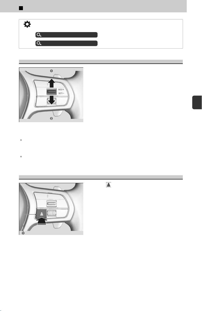
You can switch the displayed set speed measurements on the gauge or audio/
information screen between mph and km/h.
Speed/distance units
u
P.340
Customized Features
u
P.239
To Adjust the Vehicle Speed
a Pressing the RES/+/SET/− switch up
≫
Each press increases speed by about 1 mph or 1
km/h.
≫
Press and hold to increase speed by about 5 mph or 5
km/h.
b P
ressing the RES/+/SET/− switch down
≫
Each press decreases speed by about 1 mph or 1
km/h.
≫
Press and hold to decrease speed by about 5 mph or
5 km/h.
If a vehicle detected ahead is going at a speed slower than your increased set speed, ACC
with Low Speed Follow may not accelerate your vehicle. This is to maintain the set interval
between your vehicle and the vehicle ahead.
When you depress the accelerator pedal and then press down and release the RES/+/SET/−
switch, the current speed of the vehicle is set.
To Set or Change Following-Interval
Press the button (a) to change the ACC with
Low Speed Follow following-interval.
≫
Each time you press the button, the following-interval
(the interval behind a vehicle detected ahead of you)
setting cycles through furthest, far, mid, and nearest
following-intervals.
≫
Determine the most appropriate following-interval
setting based on your specific driving conditions. Be
sure to adhere to any following interval requirements
set by local regulation.
≫
The higher your vehicle’s following-speed is, the
longer the nearest, mid, far or furthest following-
interval becomes.
4
Safety Driving Assist System > Adaptive Cruise Control (ACC) with Low Speed Follow
293
4
Safety Driving Assist System
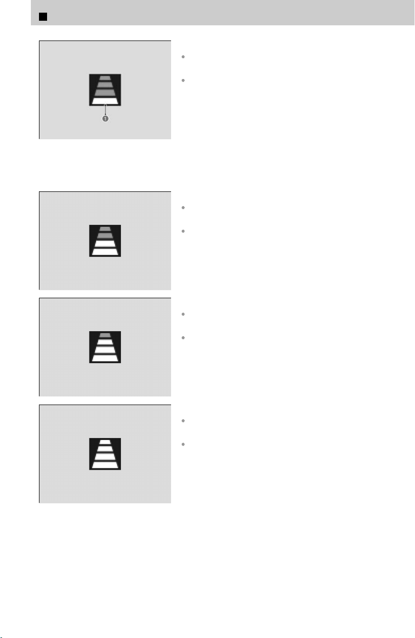
a Adaptive Cruise Control
(ACC) with Low Speed Follow
Interval Indicator
The distance between vehicles is:
About 72 feet (22 m) (vehicle speed is 50 mph [80
km/h])
About 85 feet (26 m) (vehicle speed is 65 mph [104
km/h])
The distance between vehicles is:
About 112 feet (34 m) (vehicle speed is 50 mph [80
km/h])
About 142 feet (43 m) (vehicle speed is 65 mph [104
km/h])
The distance between vehicles is:
About 154 feet (47 m) (vehicle speed is 50 mph [80
km/h])
About 200 feet (61 m) (vehicle speed is 65 mph [104
km/h])
The distance between vehicles is:
About 208 feet (63 m) (vehicle speed is 50 mph [80
km/h])
About 274 feet (83 m) (vehicle speed is 65 mph [104
km/h])
4
Safety Driving Assist System > Adaptive Cruise Control (ACC) with Low Speed Follow
294
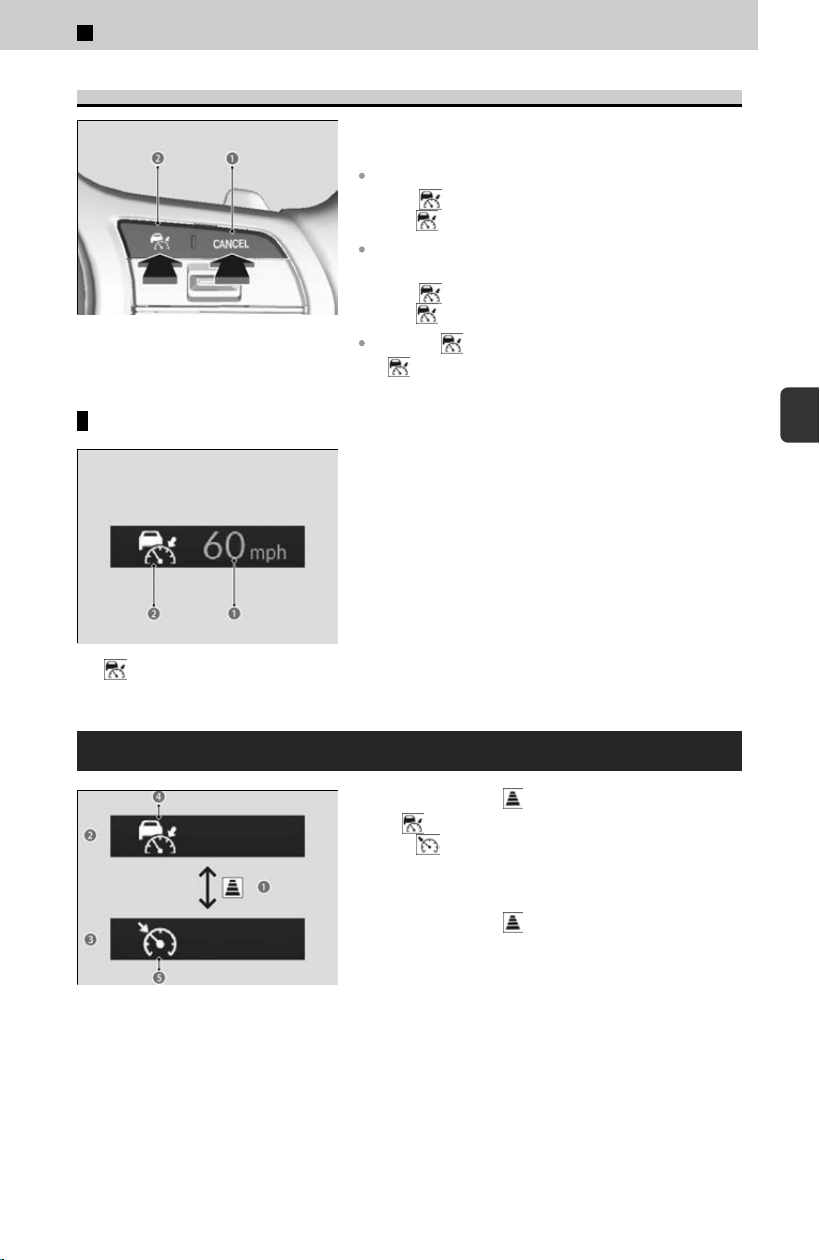
To Cancel
To cancel ACC with Low Speed Follow, do any of
the following:
Press the CANCEL button (a).
≫
The indicator (green) on the gauge changes to
the
indicator (white).
Depress the brake pedal while the vehicle is moving
forward.
≫
The indicator (green) on the gauge changes to
the
indicator (white).
Press the button (b).
≫
indicator (green) goes off.
Resuming the prior set speed
b Indicator (White)
When you turn off ACC with Low Speed Follow by
pr
essing the CANCEL button or depressing the
brake pedal, the prior set speed (a) is displayed
on the gauge in gray.
You can activate ACC with Low Speed Follow with
the prior set speed display
ed on the gauge (in
gray) by pressing the RES/+/SET/− switch up.
To Switch the Cruise Mode
b Display for ACC with Low
Speed Follow
c Display for Cruise Mode
Press and hold the
button (a) for one second.
≫
The indicator (white) (d) on the gauge changes
to the
indicator (white) (e) and switches to the
cruise mode.
To switch back to ACC with Low Speed Follow,
pr
ess and hold the button again for one
second.
You cannot switch ACC with Low Speed Follow to Cruise Control when setting a
v
ehicle speed or activating ACC with Low Speed Follow.
4
Safety Driving Assist System > Adaptive Cruise Control (ACC) with Low Speed Follow
295
4
Safety Driving Assist System
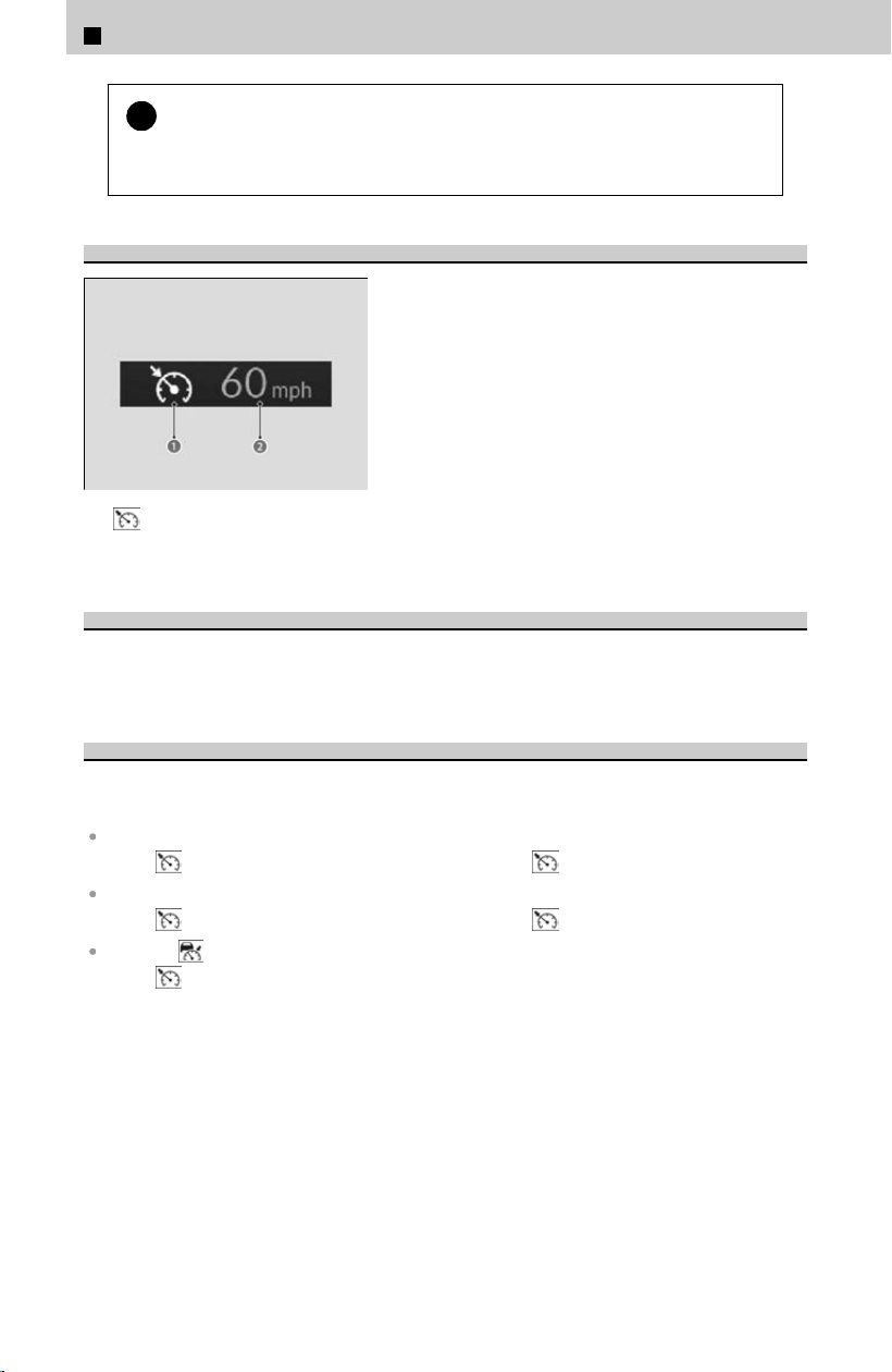
!
Always be aware which mode you are in.
When y
ou are driving in Cruise mode, the system will not assist you to maintain
a following-interval from a vehicle ahead of you.
How to Activate Cruise Mode
a Indicator (Green)
b Set Vehicle Speed (White)
When driving at 20 mph (30 km/h) or above,
pr
ess the RES/+/SET/− switch up or down.
≫
The system will start operating at the set speed.
≫
The icons and set speed will be displayed on the
gauge.
To Adjust the Vehicle Speed
The adjusting procedure for the vehicle speed is the same as for ACC with Low Speed
F
ollow.
To Cancel
Cruise control is canceled when you do any of the following or when your vehicle
speed bec
omes below 17 mph (25 km/h):
Press the CANCEL button.
≫
The indicator (green) on the gauge changes to the indicator (white).
Depress the brake pedal.
≫
The indicator (green) on the gauge changes to the indicator (white).
Press the button.
≫
The indicator (green) goes off.
4
Safety Driving Assist System > Adaptive Cruise Control (ACC) with Low Speed Follow
296
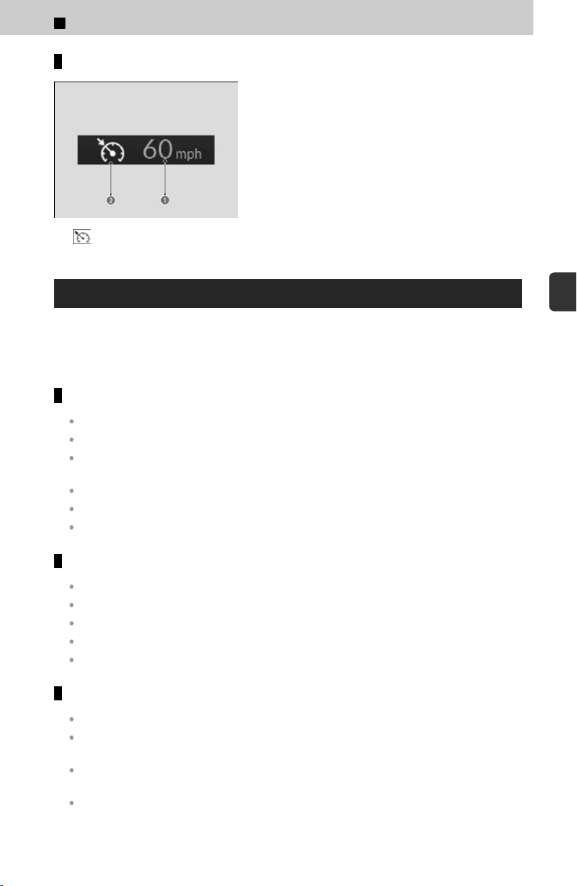
Resuming the prior set speed
b Indicator (White)
When you turn off cruise control by pressing the
C
ANCEL button or depressing the brake pedal,
the prior set speed (a) is displayed on the gauge
in gray.
You can activate cruise control with the prior set
speed display
ed on the gauge (in gray) and by
pressing the RES/+/SET/− switch up while
driving at 20 mph (30 km/h) or above.
ACC with Low Speed Follow Limitations
The system may automatically shut off under certain conditions. Some examples of
these c
onditions are listed below. Other conditions may reduce some of the ACC with
Low Speed Follow functions.
Environmental conditions
Driving in bad weather (rain, fog, snow, etc.).
Water is sprayed by or snow blown from a vehicle ahead.
Driving at night or in a dark place such as a tunnel (due to low-light conditions, the whole
vehicle may not be illuminated).
Driving into low sunlight (e.g., at dawn or dusk).
Reflections on the interior of the windshield.
When nearby radio wave emitting devices such as other automotive radar sensors.
Roadway conditions
Driving on curvy, winding, undulating, or sloping roads.
Driving on rutted roads (snowy or unpaved roads, etc.).
Puddles or a film of water is on the road surface.
Your vehicle is strongly shaken on uneven road surfaces.
Driving through a narrow metal bridge.
Vehicle conditions
The vehicle is tilted due to heavy load in the cargo area or rear seats.
The front of the camera is covered by dirt, fog, rain, mud, wet snow, accessories, stickers, or
film on the windshield.
The area around the front grille is obstructed by dirt, rain, mud, wet snow, accessories,
decals, stickers, film, etc.
The inside of the windshield is fogged.
4
Safety Driving Assist System > Adaptive Cruise Control (ACC) with Low Speed Follow
297
4
Safety Driving Assist System

An abnormal tire or wheel condition (incorrect sizes, varied sizes or construction,
improperly inflated, compact spare tire, etc.).
The suspension has been modified.
Tire chains
*
are installed.
The vehicle is towing a trailer.
Examples of conditions under which the radar and camera may not
correctly detect the vehicle ahead of you
A vehicle suddenly crosses in front of you.
The interval between your vehicle and the vehicle ahead of you is too short.
When the radar and camera cannot correctly identify the shape of the vehicle ahead of you.
Examples of conditions under which the system may not work properly
A vehicle ahead of you stops and the speed difference between your vehicle and the vehicle
ahead of you is significantly large.
When the vehicle ahead of you slows suddenly.
When a vehicle ahead of you is specially-shaped.
When a vehicle is lower in the rear than the front such as trucks that are not carrying a load,
or a narrow vehicle.
When your vehicle or the vehicle ahead of you is driving on the edge of the lane.
When the vehicle ahead of you is a narrow vehicle such as a motorcycle.
When the minimum ground clearance of a vehicle ahead of you is extremely high.
You accelerate rapidly and approach the vehicle ahead of you at high speed.
There are animals in front of your vehicle.
Your vehicle abruptly crosses over in front of an oncoming vehicle.
Automatic cancellation
The beeper sounds and a message appears on the driver information interface
when A
CC with Low Speed Follow is automatically canceled. Any of these
conditions may cause the ACC with Low Speed Follow to automatically cancel:
Bad weather (rain, fog, snow, etc.).
The vehicle ahead of you cannot be detected.
An abnormal tire condition is detected, or the tires are skidding.
Driving on a mountainous road for extended periods, or driving off road.
Abrupt steering wheel movement.
When the ABS, VSA®, CMBS™, or Low Speed Braking Control is activated.
When the ABS or VSA® system indicator comes on.
When the vehicle is stopped on a very steep slope.
When you manually apply the parking brake.
When the detected vehicle within the ACC with Low Speed Follow range is too close to your
vehicle.
When accelerating rapidly.
*: Not available on all models
4
Safety Driving Assist System > Adaptive Cruise Control (ACC) with Low Speed Follow
298

The front of the camera is obstructed by dirt, fog, rain, mud, wet snow, accessories, decals,
stickers, film, etc.
The area around the front grille is obstructed by dirt, rain, mud, wet snow, accessories,
decals, stickers, film, etc.
The vehicle is loaded heavy load in the cargo area or rear seats.
When passing through an enclosed space, such as a tunnel.
The vehicle has repeatedly applied the brakes to maintain the set speed (for example, you
are descending a long slope).
When the parking brake and brake system indicator (amber) comes on.
When the system doesn’t detect any driving actions from the driver for a certain amount of
time while the LKAS or Traffic Jam Assist is also activated.
The engine is stopped.
The driver’s seat belt is unfastened when the vehicle is stationary.
The vehicle stops for more than 10 minutes.
4
Safety Driving Assist System > Adaptive Cruise Control (ACC) with Low Speed Follow
299
4
Safety Driving Assist System
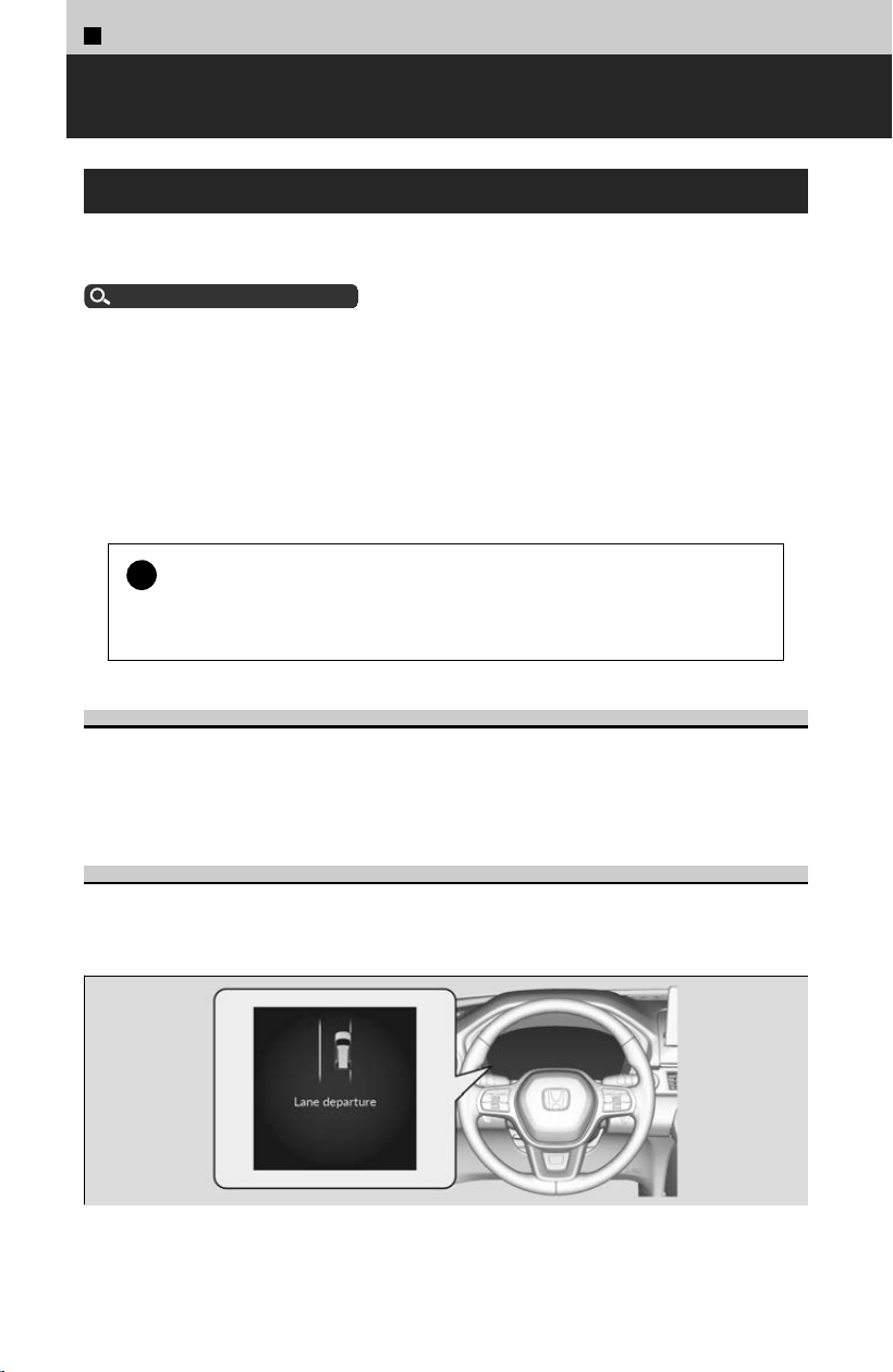
4
Safety Driving Assist System >
Lane Keeping Assist System (LKAS)
About LKAS
Provides steering input to help keep the vehicle in the middle of a detected lane and
pr
ovides tactile and visual alerts if the vehicle is detected drifting out of its lane.
Front Sensor Camera
u
P.270
Important Safety Reminders
The LKAS is for your convenience only. It is not an autonomous driving system and
al
ways requires driver attention and control. The system does not work if you take
your hands off the steering wheel or fail to steer the vehicle.
The LKAS is convenient when it is used on expressways or freeways.
It is always your responsibility to safely operate the vehicle and avoid collisions.
!
If the vehicle drifts toward either left or right lane line due to the
s
ystem applying torque, turn off the LKAS and have your vehicle
checked by a dealer.
Lane Keep Support Function
Provides assistance to keep the vehicle in the center of the lane. When the vehicle
nears a whit
e or yellow line, steering force of the electric power steering will become
stronger.
Lane Departure Warning Function
In some driving situations, when the system detects that the vehicle has departed
fr
om its lane, the LKAS alerts you with slight steering wheel vibration as well as a
warning display.
300
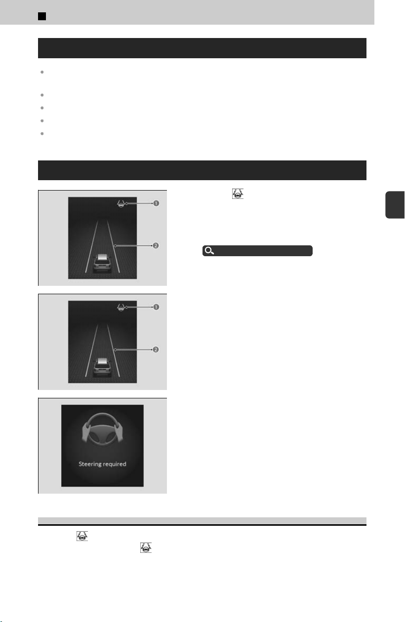
Operating Conditions
The lane in which you are driving has detectable lane markers on both sides, and your vehicle
is in the center of the lane.
You are driving on a straight or slightly curved road.
The turn signals are off.
The brake pedal is not suddenly depressed.
The vehicle is traveling between about 45 and 90 mph (72 and 145 km/h).
How to Activate LKAS
[1] Press the button.
≫
LKAS indicator (white) (a) appears on the
gauge. The system is standby.
≫
If traffic lane lines are detected, white lines (b)
appear on the gauge.
Operating Device
u
P.268
[2] Keep your vehicle near the center of the
lane while driving.
≫
The system starts operating when the LKAS
indicator (green) (a) and the green lines (b)
appear.
If the driver takes their hands off the steering
wheel or does not adequately maintain control of
steering, the warning message will appear.
If the driver does not grip the steering wheel after
the warning display has repeatedly appeared, a
warning buzzer will sound and LKAS will be
canceled.
To Cancel
Press the
button.
≫
To operate LKAS, press the button again.
≫
The LKAS is turned off every time you stop the engine, even if you turned it on the last time
you drove the vehicle.
4
Safety Driving Assist System > Lane Keeping Assist System (LKAS)
301
4
Safety Driving Assist System
The LKAS May Be Automatically Suspended When:
When the LKAS is suspended under the following circumstances, the LKAS indicator
chang
es green to white, and the beeper sounds (if activated).
Your vehicle is driving to the right or the left of the lane.
The system fails to detect lane lines.
The steering wheel is turned quickly.
You fail to steer the vehicle.
Driving through a sharp curve.
The ABS, VSA®, or CMBS™ is activated.
The brake pedal is suddenly depressed.
Driving at a speed in excess of approximately 94 mph (150 km/h).
Once these conditions no longer exist, the LKAS automatically resumes.
You can change the LKAS suspended beep on and off.
Customized Features
u
P.239
LKAS Conditions and Limitations
The system may not detect lane markings (in white or yellow), and LKAS may not
function pr
operly under certain conditions, including the following:
Environmental conditions
There is little contrast between lane lines and the roadway surface.
Driving in bad weather (rain, fog, snow, etc.).
Driving on a snowy or wet roadway.
Driving into low sunlight (e.g., at dawn or dusk).
Shadows of adjacent objects (trees, buildings, guard rails, vehicles, etc.) are parallel to
white (or yellow) lines.
Sudden changes between light and dark, such as the entrance or exit of a tunnel or the
shadows of trees, buildings, etc.
Driving at night or in a dark place such as a tunnel (due to low-light conditions, lane lines or
the road surface may not be illuminated).
The distance between your vehicle and the vehicle ahead of you is too short, and lane lines
and the road surface are not visible.
Strong light is reflected onto the roadway.
Roadway conditions
Driving on a road with temporary lane markings.
Faint, multiple, or varied lane markings are visible on the roadway due to road repairs or old
lane markings.
The roadway has merging, split, or crossing lines, such as at an intersection or crosswalk.
The lane markings are extremely narrow, wide, or changing.
4
Safety Driving Assist System > Lane Keeping Assist System (LKAS)
302

Part of the lane markings are hidden by an object, such as a vehicle.
The road is hilly or the vehicle is approaching the crest of a hill.
Your vehicle is strongly shaken on uneven road surfaces.
When objects on the road (curb, guard rail, pylons, etc.) are recognized as white (or yellow)
lines.
Driving on rough or unpaved roads, or over bumpy surfaces.
Driving on roads with double lane lines.
Driving on snowy or slippery roads.
The pavement is only partially visible due to snow or puddles on the road.
There is a film of water or puddles on the road surface.
White (or yellow) lines are not recognized correctly due to road conditions such as curves,
twists, or hills.
Driving on unpaved or rutted roads.
Passing through an exit or an interchange.
Vehicle conditions
When lighting is weak due to dirt covering the headlight lenses, or there is poor visibility in a
dark place due to the headlights being improperly adjusted.
The front of the camera is obstructed by dirt, fog, rain, mud, wet snow, accessories, decals,
stickers, film, etc.
Driving at night or in a dark place (e.g., a tunnel) with the headlights off.
There is residue on the windshield from the windshield wipers.
The inside of the windshield is fogged.
An abnormal tire or wheel condition (incorrect sizes, varied sizes or construction,
improperly inflated, compact spare tire, etc.).
The vehicle is tilted due to a heavy load in the cargo area or rear seats.
The suspension has been modified.
Tire chains
*
are installed.
The vehicle is towing a trailer.
*: Not available on all models
4
Safety Driving Assist System > Lane Keeping Assist System (LKAS)
303
4
Safety Driving Assist System
4
Safety Driving Assist System >
Traffic Jam Assist
About Traffic Jam Assist
The T
raffic Jam Assist system uses a camera mounted to the upper portion of the
windshield to detect and monitor left and right white (or yellow) traffic lane lines.
Based on inputs from the camera, the system can apply steering torque to keep your
vehicle in the center of the detected lane.
Front Sensor Camera
u
P.270
Important Safety Reminders
Traffic Jam As
sist is for your convenience only. It is not an autonomous driving system
and always requires driver attention and control.
The system does not work if you take your hands off the steering wheel or fail to steer
the vehicle.
Traffic Jam Assist is convenient when it is used on expressways or freeways.
It is always your responsibility to safely operate the vehicle and avoid collisions.
!
Do not use T
raffic Jam Assist in any of the following situations:
You are traveling on a road with sharp curves.
≫
The system may not allow your vehicle to respond in a manner best suited
for the road conditions.
You are entering a toll booth, interchange, service area, or parking area.
You are driving in adverse weather (rain, fog, snow, etc.).
The surface of the road is slippery; for example, it is icy or covered with
snow.
≫
The tires may slip, causing you to lose control of the vehicle.
!
If your vehicle veers too far to the right or the left of the white (or
y
ellow) traffic lane lines while Traffic Jam Assist is active, deactivate
Traffic Jam Assist and have your vehicle checked by a dealer.
Lane Keep Support Function
When you are in heavy tr
affic and Lane Keeping Assist System (LKAS) is active, the
traffic jam assist system, upon detecting the traffic lane lines, will apply steering
torque to help keep your vehicle in the center of the lane.
304
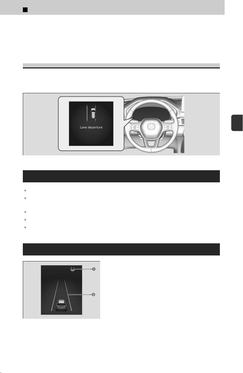
≫
When the driver takes full control of the steering, the steering assist function is temporarily
canceled.
≫
The torque applied to the steering may not be noticeable when the driver has full control of
the steering, or when the surface of the road is rough or uneven.
Lane Departure Warning Function
In some driving situations, when the system detects that the vehicle has departed
fr
om its lane, the Traffic Jam Assist alerts you with an audible alert as well as a
warning display.
Operating Conditions
LKAS is activated.
The lane in which you are driving has detectable lane markers on both sides, and your vehicle
is in the center of the lane.
You are driving on a straight or slightly curved road.
The driver is gripping the steering wheel.
The vehicle is traveling between about 0 and 45 mph (0 and 72 km/h).
How to Activate Traffic Jam Assist
Keep your vehicle near the center of the lane
while driving.
≫
The LKAS indicator (a) changes from white to green,
and white lines (b) change to green once the system
starts operating after detecting the left and right lane
markings.
4
Safety Driving Assist System > Traffic Jam Assist
305
4
Safety Driving Assist System
If the driver takes their hands off the steering
wheel or does not adequately maintain control of
steering, the warning will appear.
Canceling Traffic Jam Assist
Press the LKAS button to cancel T
raffic Jam Assist.
≫
To operate Traffic Jam Assist, press the button again.
Traffic Jam Assist may be Automatically Suspended when:
The system fails to detect lane lines.
The steering wheel is turned sharply.
You fail to steer the vehicle.
You are driving through a sharp curve.
The ABS, VSA®, CMBS™, or Low Speed Braking Control is activated.
Your vehicle is driving to the right or the left of the lane.
The brake pedal is suddenly depressed.
Once these conditions no longer exist, T
raffic Jam Assist automatically resumes.
You can change the setting for the Traffic Jam Assist suspended beep on and off
when you select the Lane Keeping Assist Suspend Beep on the gauge.
Customized Features
u
P.239
Traffic Jam Assist Limitations
The system may not detect lane markings and therefore may not keep the vehicle in
the middle o
f the lane under certain conditions, including the following:
Environmental conditions
There is little contrast between lane lines and the roadway surface.
Driving in bad weather (rain, fog, snow, etc.).
Driving on a snowy or wet roadway.
Driving into low sunlight (e.g., at dawn or dusk).
Shadows of adjacent objects (trees, buildings, guard rails, vehicles, etc.) are parallel to
white (or yellow) lines.
Sudden changes between light and dark, such as the entrance or exit of a tunnel or the
shadows of trees, buildings, etc.
4
Safety Driving Assist System > Traffic Jam Assist
306

Driving at night or in a dark place such as a tunnel (due to low-light conditions, lane lines or
the road surface may not be illuminated).
When the lane lines or road surface are not visible, such as when the distance to the vehicle
in front of you is extremely short or when at an intersection.
Strong light is reflected onto the roadway.
Roadway conditions
Driving on a road with temporary lane markings.
Faint, multiple, or varied lane markings are visible on the roadway due to road repairs or old
lane markings.
The roadway has merging, split, or crossing lines, such as at an intersection or crosswalk.
The lane markings are extremely narrow, wide, or changing.
Part of the lane markings are hidden by an object, such as a vehicle.
The road is hilly or the vehicle is approaching the crest of a hill.
Your vehicle is strongly shaken on uneven road surfaces.
When objects on the road (curb, guard rail, pylons, etc.) are recognized as white (or yellow)
lines.
Driving on rough or unpaved roads, or over bumpy surfaces.
Driving on roads with double lane lines.
Driving on snowy or slippery roads.
The pavement is only partially visible due to snow or puddles on the road.
There is a film of water or puddles on the road surface.
White (or yellow) lines are not recognized correctly due to road conditions such as curves,
twists, or hills.
Driving on unpaved or rutted roads.
Passing through an exit or an interchange.
Vehicle conditions
When lighting is weak due to dirt covering the headlight lenses, or there is poor visibility in a
dark place due to the headlights being improperly adjusted.
The front of the camera is covered by dirt, fog, rain, mud, wet snow, accessories, stickers, or
film, etc. on the windshield.
Driving at night or in a dark place (e.g., a tunnel) with the headlights off.
There is residue on the windshield from the windshield wipers.
The inside of the windshield is fogged.
An abnormal tire or wheel condition (incorrect sizes, varied sizes or construction,
improperly inflated, compact spare tire, etc.).
The vehicle is tilted due to a heavy load in the cargo area or rear seats.
The suspension has been modified.
Tire chains
*
are installed.
The vehicle is towing a trailer.
*: Not available on all models
4
Safety Driving Assist System > Traffic Jam Assist
307
4
Safety Driving Assist System
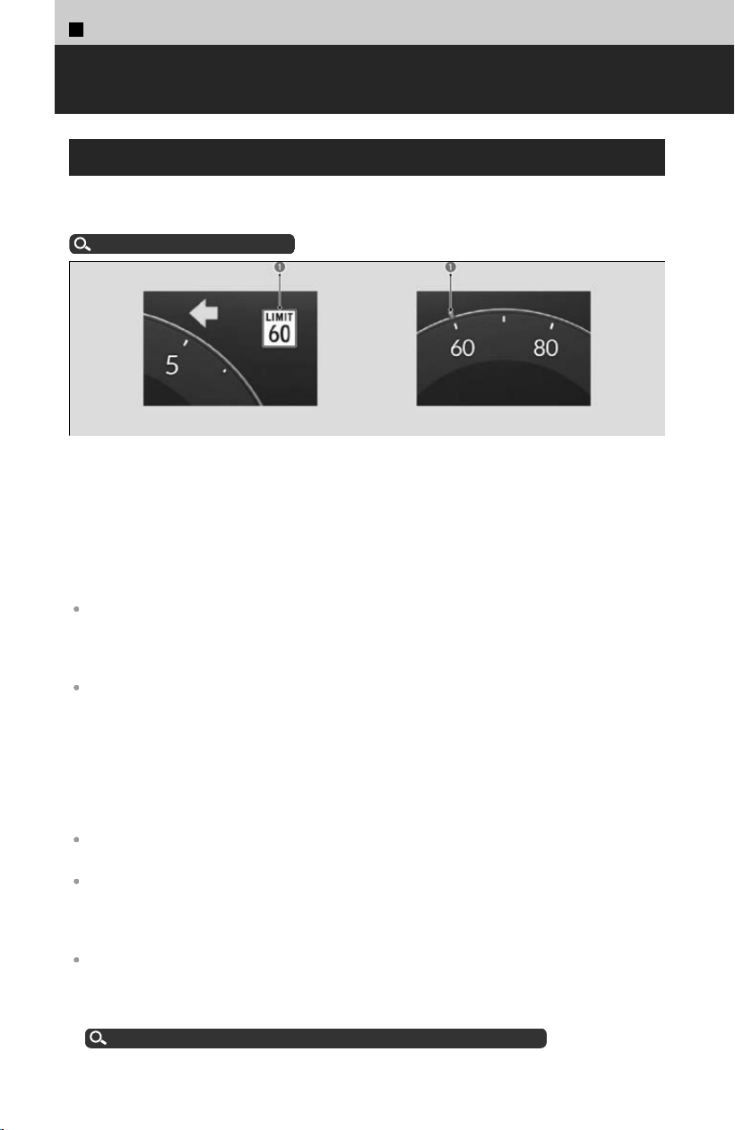
4
Safety Driving Assist System >
Traffic Sign Recognition System
About Traffic Sign Recognition System
While driving, road signs (such as speed limit signs) detected by the front sensor
camer
a are displayed on the gauge to inform you of road sign information.
Front Sensor Camera
u
P.270
When the camera detects traffic signs while the vehicle is being driven, the system
displays recognized signs in your vehicle for a programmed time and distance. If a
speed limit sign (a) is detected and the vehicle exceeds the speed limit by a
programmed threshold, the speed limit sign icon will blink.
≫
If the system does not detect any traffic signs while you are driving, the sign icon will not be
displayed.
Not all signs may be displayed, but any signs posted on roadsides should not be ignored.
The system does not work on the designated traffic signs of all the countries you travel, nor in
all situations. Do not rely too much on the system. Always drive at speeds appropriate for the
road conditions.
Never apply a film or attach any objects to the windshield that could obstruct the camera’s
field of vision and cause the system to operate abnormally. Scratches, nicks, and other
damage to the windshield within the camera’s field of vision can cause the system to operate
abnormally. If this occurs, we recommend that you replace the windshield with a genuine
Honda replacement windshield. Making even minor repairs within the camera’s field of vision
or installing an aftermarket replacement windshield may also cause the system to operate
abnormally. After replacing the windshield, have a dealer recalibrate the camera. Proper
calibration of the camera is necessary for the system to operate properly.
If the system does not detect any traffic signs while you are driving, the sign icon will not be
displayed.
To help reduce the likelihood that high interior temperatures will cause the camera’s sensing
system to shut off, find a shady area or face the front of the vehicle away from the sun when
parking. If you use a reflective sun shade, do not allow it to cover the camera housing.
Covering the camera can concentrate heat on it.
The system’s ability to accurately notify the driver of the speed limit is dependent on certain
conditions such as the units displayed on the traffic sign as well as the speed and direction of
travel of the vehicle. In some cases, the system may display false warnings or other
inaccurate information.
Traffic Sign Recognition System Conditions and Limitations
u
P.309
308
You can turn the Traffic Sign Recognition System on and off.
Customized Features
u
P.239
If your vehicle exceeds the detected speed limit, an icon representing the speed limit
sign for the current area will blink in the display.
Customized Features
u
P.239
The unit for speed limits (mph or km/h) varies from country to country. Just after
entering a country whose unit differs from the one of the country from which you
came, The Traffic Sign Recognition System may not work correctly.
Customized Features
u
P.239
!
When the tr
affic sign recognition system malfunctions, appears on
the gauge. If this icon does not disappear, have your vehicle checked
by a dealer.
Operating Conditions
The sign icon also may switch to another one or disappear when:
The end of speed limit or other designated limit is detected.
You make a turn with a turn signal at an intersection.
Traffic Sign Recognition System Limitations
The T
raffic Sign Recognition system may incorrectly recognize, be slow to identify, or
fail to recognize the traffic sign in the following cases.
Environmental conditions
Driving into low sunlight (e.g., at dawn or dusk).
Strong light is reflected onto the roadway.
Driving at night, in dark areas such as long tunnels.
Driving in bad weather (rain, fog, snow, etc.).
Sudden changes between light and dark, such as the entrance or exit of a tunnel or the
shadows of trees, buildings, etc.
Water is sprayed by or snow blown from a vehicle ahead.
Roadway conditions
Your vehicle is strongly shaken on uneven road surfaces.
4
Safety Driving Assist System > Traffic Sign Recognition System
309
4
Safety Driving Assist System

Vehicle conditions
When lighting is weak due to dirt covering the headlight lenses, or there is poor visibility in a
dark place due to the headlights being improperly adjusted.
The front of the camera is obstructed by dirt, fog, rain, mud, wet snow, accessories, decals,
stickers, film, etc.
Driving at night or in a dark place (e.g., a tunnel) with the headlights off.
There is residue on the windshield from the windshield wipers.
The inside of the windshield is fogged.
An abnormal tire or wheel condition (incorrect sizes, varied sizes or construction,
improperly inflated, compact spare tire, etc.).
The vehicle is tilted due to heavy load in the cargo area or rear seats.
The suspension has been modified.
Tire chains
*
are installed.
The vehicle is towing a trailer.
The position or the condition of the traffic sign
The sign is in a place that makes it hard to find.
The sign is located far away from your vehicle.
The sign is located where it is hard for headlight beams to reach.
The sign is on a corner or bend in the road.
The sign is faded or bent.
The sign is rotated or damaged.
The sign is covered with mud, snow, or frost.
Part of the sign is hidden by the trees, or is in the shadow of a vehicle or other object.
Light (such as a streetlight) is reflected on the surface of the sign, or it is hidden in shadow.
The sign is too bright or too dark (electric signs).
Small signs (auxiliary signs, etc.).
Other conditions
When you are driving at a high speed.
The T
raffic Sign Recognition System may not operate correctly, such as displaying
signs that do not adhere to the actual regulations for the roadway or do not exist at
all in the following cases.
≫
A speed limit sign may display at a higher or lower speed than the actual speed limit.
There is a supplementary sign with further information such as weather, time, vehicle type,
school zone, etc.
Figures on the sign are hard to read (electric signs, numbers on the sign are blurred, etc.).
The sign is in the vicinity of the lane you are driving in, even though it is not for the lane,
such as a speed limit sign situated at an exit or an intersection between the side road and
the main road.
There are things that look similar in color or shape to recognized objects (similar sign,
electric sign, signboard, structure, etc.).
*: Not available on all models
4
Safety Driving Assist System > Traffic Sign Recognition System
310
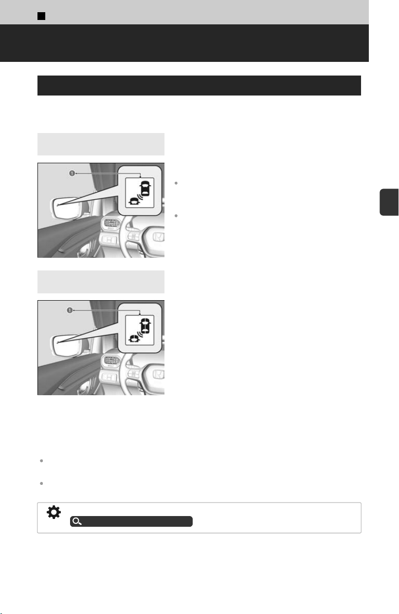
4
Safety Driving Assist System >
Blind Spot Information System
About Blind Spot Information System
When the system detects vehicles approaching from behind in adjacent lanes, the
appr
opriate indicator comes on, providing assistance when you change lanes.
4
Models without Multi View
Camera System
4
Models with Multi View
Camera System
When the system detects a vehicle, the blind spot
information system alert indicator (a) on the
outside door mirror on both sides comes on in the
following situations:
A vehicle approaches you from behind to overtake
you at a speed difference of no more than about 31
mph (50 km/h).
You pass a vehicle at a speed difference of no more
than about 12 mph (20 km/h).
When you operate the turn signal lever in the direction of a detected vehicle, the blind
spot inf
ormation system alert indicator blinks and the beeper sounds.
The system is for your convenience only. Even if an object is within the alert zone, the
following situations may occur:
The blind spot information system alert indicator does not come on and the Blind spot
information system not available message appears on the driver information interface.
The blind spot information system alert indicator may come on even with the message
displayed.
You can change the settings for the blind spot information system.
Customized Features
u
P.239
Important Safety Reminder
311
4
Safety Driving Assist System
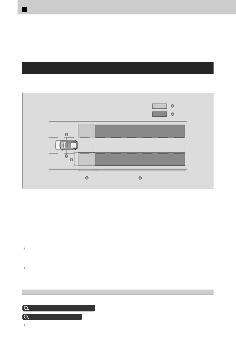
Like all assistance systems, the blind spot information system has limitations. Always
look in your mirrors, to either side of your vehicle, and behind you for other vehicles
before changing lanes. Overreliance on the blind spot information system may result
in a collision.
System Operation
The system activates when your vehicle is moving forward at about 20 mph (32 km/h)
or abo
ve.
a Alert zone 1
b Alert zone 2
c Radar Sensors: Underneath the rear bumper corners
d Approx. 1.6 ~ 10 feet (0.5 ~ 3 meters) from vehicle side.
e Approx. 10 feet (3 meters) from rear bumper.
f Approx. 10 ~ 82 feet (3 ~ 25 meters) behind from rear bumper. (The faster the
approaching vehicle, the further away it will be detected.)
The initially set alert zone is alert zone 1. Over time, after the vehicle has been driven on
straight roads with traffic and roadside objects, the system will adapt and expand the alert
zones (alert zone 1 and 2).
If the rear bumper or any system components are repaired, the system will revert to alert
zone 1 only until it is able to adapt and expand to alert zone 1 and 2.
Blind Spot Information System On and Off
You can turn the system on and off using the driver information interface.
Switching the Display
u
P.334
Safety Support
u
P.338
The blind spot information system will stay on the previously selected on or off setting each
time you start the engine.
4
Safety Driving Assist System > Blind Spot Information System
312
!
Turn the system off when towing a trailer. The system may not work
pr
operly for the following reasons:
The added mass tilts the vehicle and changes the radar coverage.
The trailer itself can be detected by the radar sensors, causing the blind spot
information system alert indicator to come on.
Blind Spot Information System Limitations
For proper blind spot information system operation:
Always keep the rear bumper and area around the radar sensors clean.
Do not cover the rear bumper corner area with labels or stickers of any kind.
The blind spot information system alert indicator may not come on under the
f
ollowing conditions:
There is a large speed difference between your vehicle and the vehicle in the adjacent lane.
A vehicle is parked in a side lane.
An object not detected by the radar sensors approaches or passes your vehicle.
The vehicle driving in the adjacent lane is a motorcycle or other small vehicle.
The blind spot information system may not operate correctly under the following
c
onditions:
Making a turn at an intersection.
Objects (guard rails, poles, trees, etc.) are detected.
An object that does not reflect radio waves well or a motorcycle is in the alert zone.
Driving on a curved road.
A vehicle is moving from a far lane to the adjacent lane.
The system picks up signal interference such as other radar sensors from another vehicle or
strong radio wave transmitted from a facility nearby.
The rear bumper or the area around the radar sensors is covered by dirt, mud, snow, ice, etc.
The rear bumper or the area around the radar sensors has been damaged or deformed.
In bad weather (heavy rain, snow, and fog).
Making a short turn or driving on a bumpy road that slightly tilts the vehicle.
An object such as a bicycle rack is attached to the rear of the vehicle.
Driving on snowy or slippery roads.
!
Have your vehicle checked by a dealer if the rear bumper or area
ar
ound the radar sensors is strongly impacted, or if the rear bumper or
any system components need to be repaired.
4
Safety Driving Assist System > Blind Spot Information System
313
4
Safety Driving Assist System
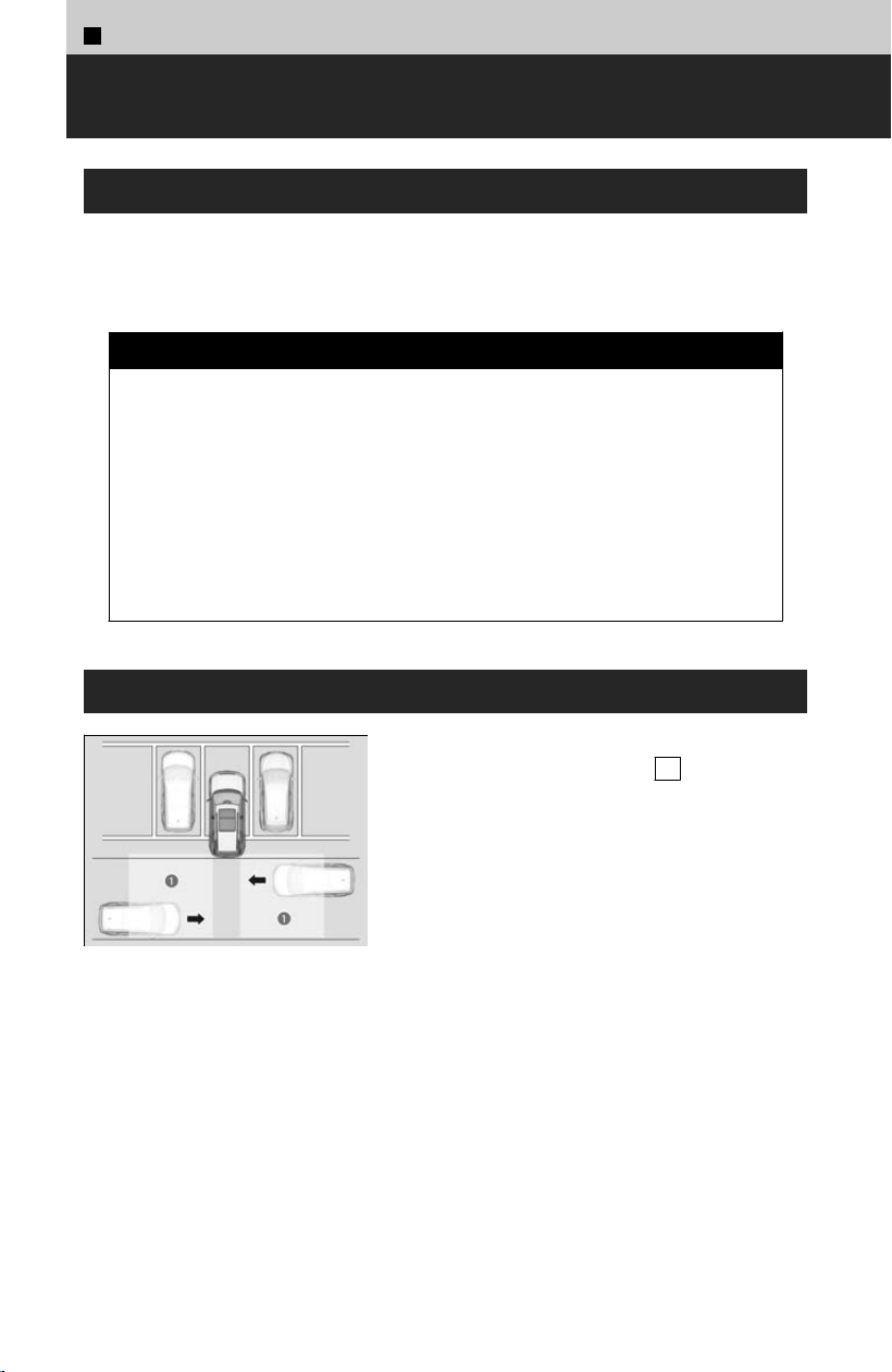
4
Safety Driving Assist System >
Cross Traffic Monitor
About Cross Traffic Monitor
Monitors the rear corner areas using the radar sensors when reversing, and alerts you
if a v
ehicle approaching from a rear corner is detected.
The system is convenient when you are backing out of a parking space.
3 CAUTION
Cross T
raffic Monitor cannot detect all approaching vehicles and may not
detect an approaching vehicle at all.
Failure to visually confirm that it is safe to back up the vehicle before doing
so may result in a collision.
Do not solely rely on the system when reversing; always also use your
mirrors, and look behind and to the sides of your vehicle before reversing.
System Operation
a Detection Range
When the vehicle speed is less than about 3 mph
(5 km
/h), the shift position is in R , and the
system is ON, the system will detect vehicles
approaching from either rear corner and alert you
with a buzzer and a visual indication.
The system will not detect a vehicle that
approaches from directly behind your vehicle, nor
will it provide alerts about a detected vehicle
when it moves directly behind your vehicle.
The system does not provide alerts for a vehicle
that is moving away from your vehicle, and it may
alert for pedestrians, bicycles, or stationary
objects.
314
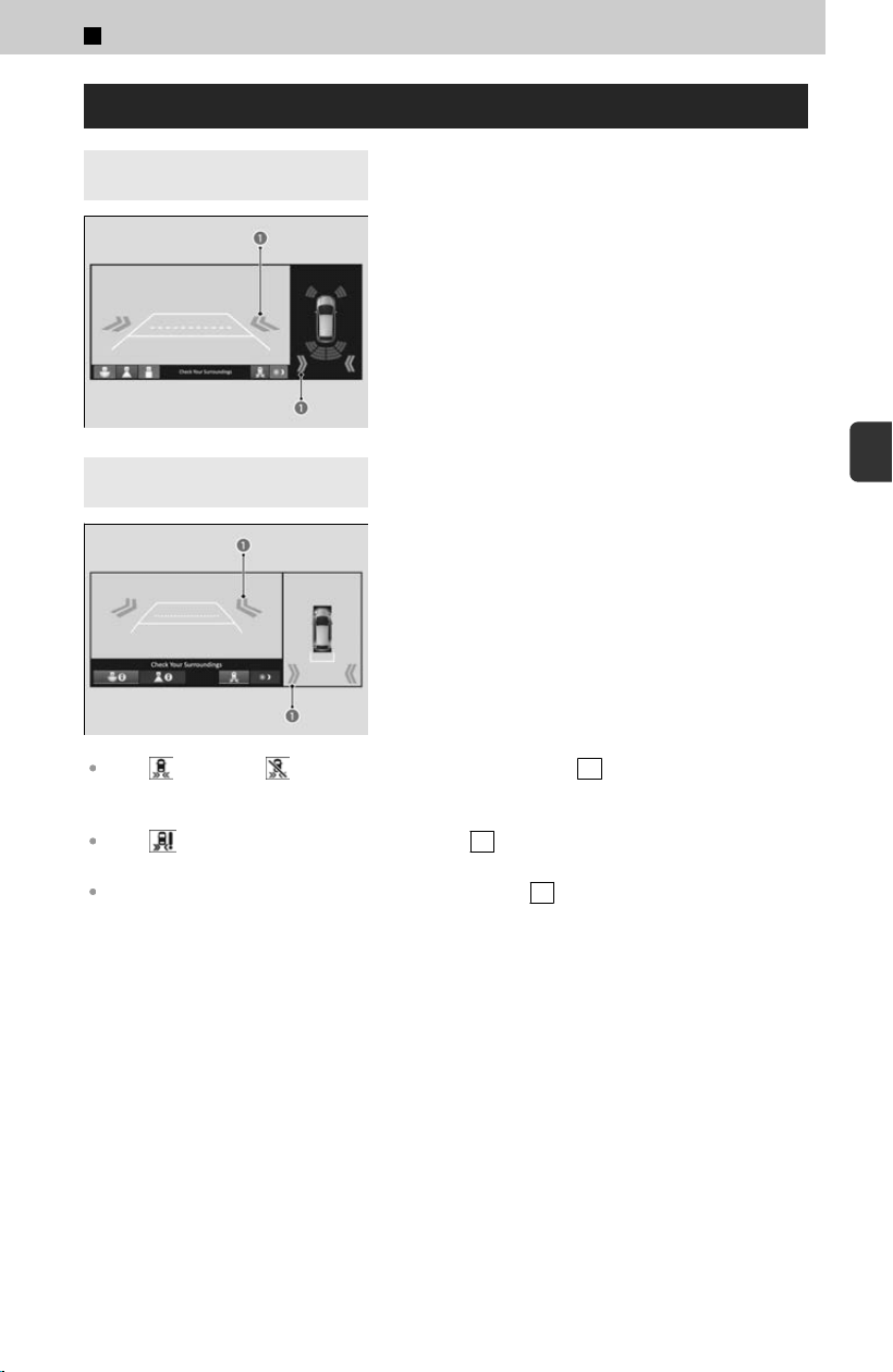
About Screen Display
4
Models with rear view
camera
4
Models with multi view
camera system
An arrow icon (a) appears on the side a vehicle
is approaching.
If the changes to in amber when the transmission is in R , mud, snow or ice, etc.
may have accumulated in the vicinity of the sensor. The system is temporarily canceled.
Check the bumper corners for any obstructions, and thoroughly clean the area if necessary.
If the comes on when the transmission is in R , there may be a problem with the Cross
Traffic Monitor system. Do not use the system and have your vehicle checked by a dealer.
If the display remains the same with the transmission in R , there may be a problem with
the rear camera system and the Cross Traffic Monitor system. Do not use the system and have
your vehicle checked by a dealer.
4
Safety Driving Assist System > Cross Traffic Monitor
315
4
Safety Driving Assist System
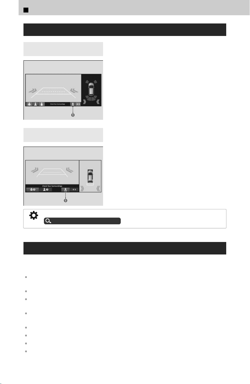
Cross Traffic Monitor On and Off
4
Models with rear view
camera
4
Models with multi view
camera system
The system can be turned on and off on the
audio/information screen by selecting the Cross
Traffic Monitor icon (a).
You can also switch the system on and off using the audio/information screen.
Customized Features
u
P.239
Cross Traffic Monitor Limitations
Cross T
raffic Monitor may not detect or may delay alerting an approaching vehicle, or
may alert without an approaching vehicle under the following conditions:
An obstacle, such as another vehicle or a wall near your vehicle’s rear bumper, is blocking the
radar sensor’s scope.
Your vehicle is moving at a speed of about 3 mph (5 km/h) or higher.
A vehicle is approaching at a speed other than between about 6 and 16 mph (10 and 25
km/h).
The system picks up external interference such as other radar sensors from another vehicle or
strong radio wave transmitted from a facility nearby.
Either corner of the rear bumper is covered with snow, ice, mud or dirt.
When there is bad weather.
Your vehicle is on an incline.
Your vehicle is tilted due to a heavy load in the rear.
4
Safety Driving Assist System > Cross Traffic Monitor
316

Your vehicle is reversing toward a wall, a pole, a vehicle, and so on.
Driving on snowy or slippery roads.
!
If the rear bumper or the sensors have been improperly repaired or
the r
ear bumper has been deformed, have the vehicle checked by a
dealer.
!
For proper operation, always keep the rear bumper corner area clean.
Do not c
over the rear bumper corner area with labels or stickers of any kind.
4
Safety Driving Assist System > Cross Traffic Monitor
317
4
Safety Driving Assist System
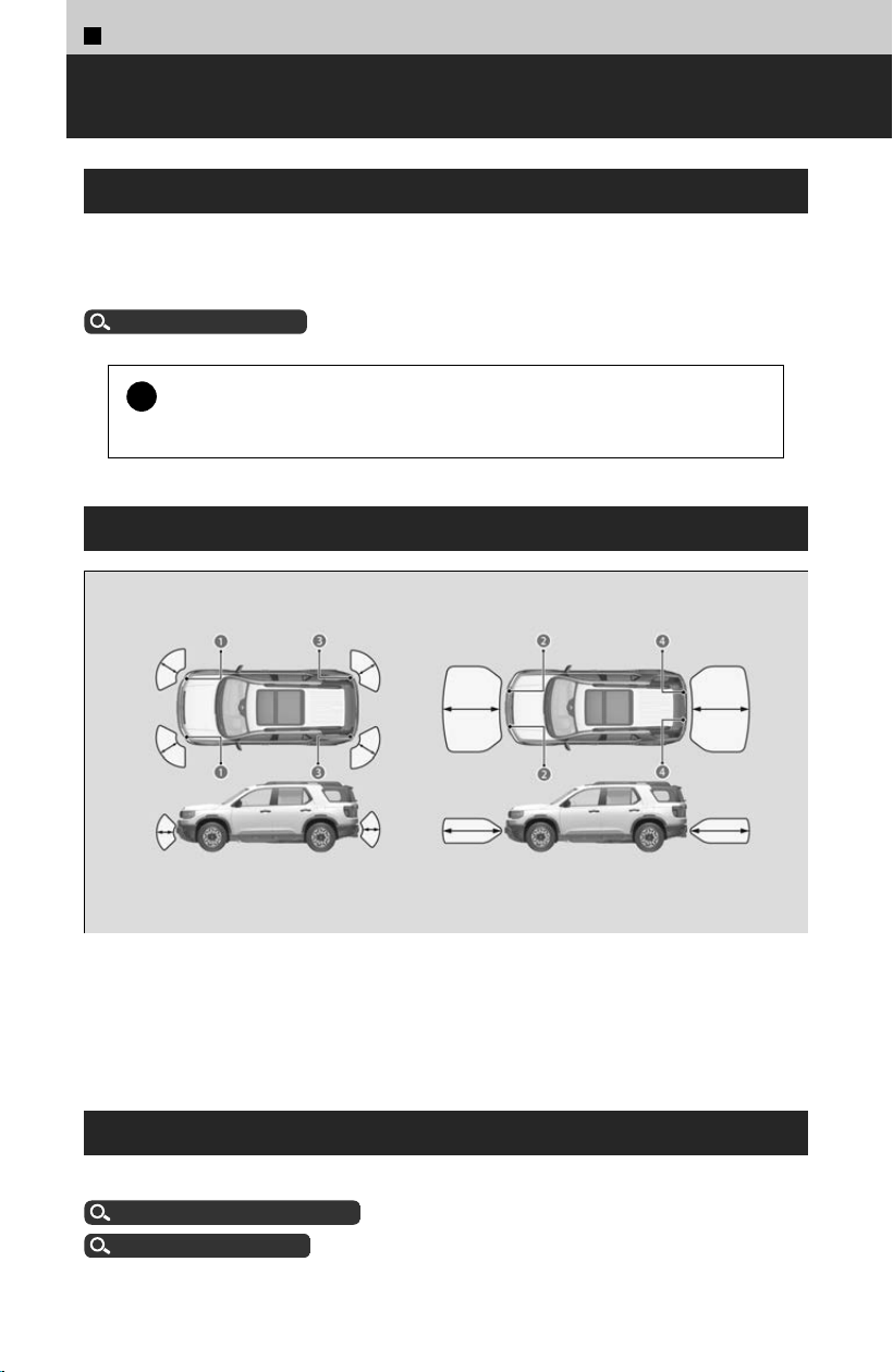
4
Safety Driving Assist System >
Parking Sensor System
About Parking Sensor System
The corner and center sensors monitor obstacles around your vehicle, and the beeper
and display let y
ou know the approximate distance between your vehicle and the
obstacle.
Sonar Sensors
u
P.272
!
Even when the system is on, always c
onfirm if there is no obstacle
near your vehicle before parking.
The Sensor Location and Range
a Front Corner Sensors
b Front Center Sensors
c Rear Corner Sensors
d Rear Center Sensors
Parking Sensor System On and Off
You can turn the system on and off using the driver information interface.
Switching the Display
u
P.334
Safety Support
u
P.338
318
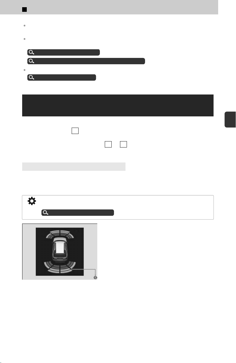
The system is in the previously selected on or off setting each time you turn the power mode
on.
You can turn the rear parking sensor system on and off. If only the rear parking sensors are
turned off, the Low Speed Braking Control System will not work when reversing.
Customized Features
u
P.239
Low Speed Braking Control System ON/OFF
u
P.282
When the Drive Mode is in TOW mode, the rear parking sensor system will turn off.
Drive Mode System
u
P.159
Operations When an Obstacle Has Been
Detected
The front corner, rear corner, and rear center sensors start to detect an obstacle when
the tr
ansmission is in R , and the vehicle speed is less than 5 mph (8 km/h).
The front corner and front center sensors start to detect an obstacle when the shift
position is in any position other than P or R , and the vehicle speed is less than 5
mph (8 km/h).
4
Models with Multi View Camera System
When the system detects that the distance between your vehicle and any obstacles in
fr
ont of it is decreasing, the forward camera image will display on the screen. When
obstacles are no longer detected, the display will return to the previous screen.
You can customize whether or not to display the forward camera image when an
obstacle is detected.
Customized Features
u
P.239
The indicators (a) show the location of the
detected location on the driver information
interface.
The indicators (a) also sho
w the position of the detected location on the audio/
information screen.
4
Safety Driving Assist System > Parking Sensor System
319
4
Safety Driving Assist System
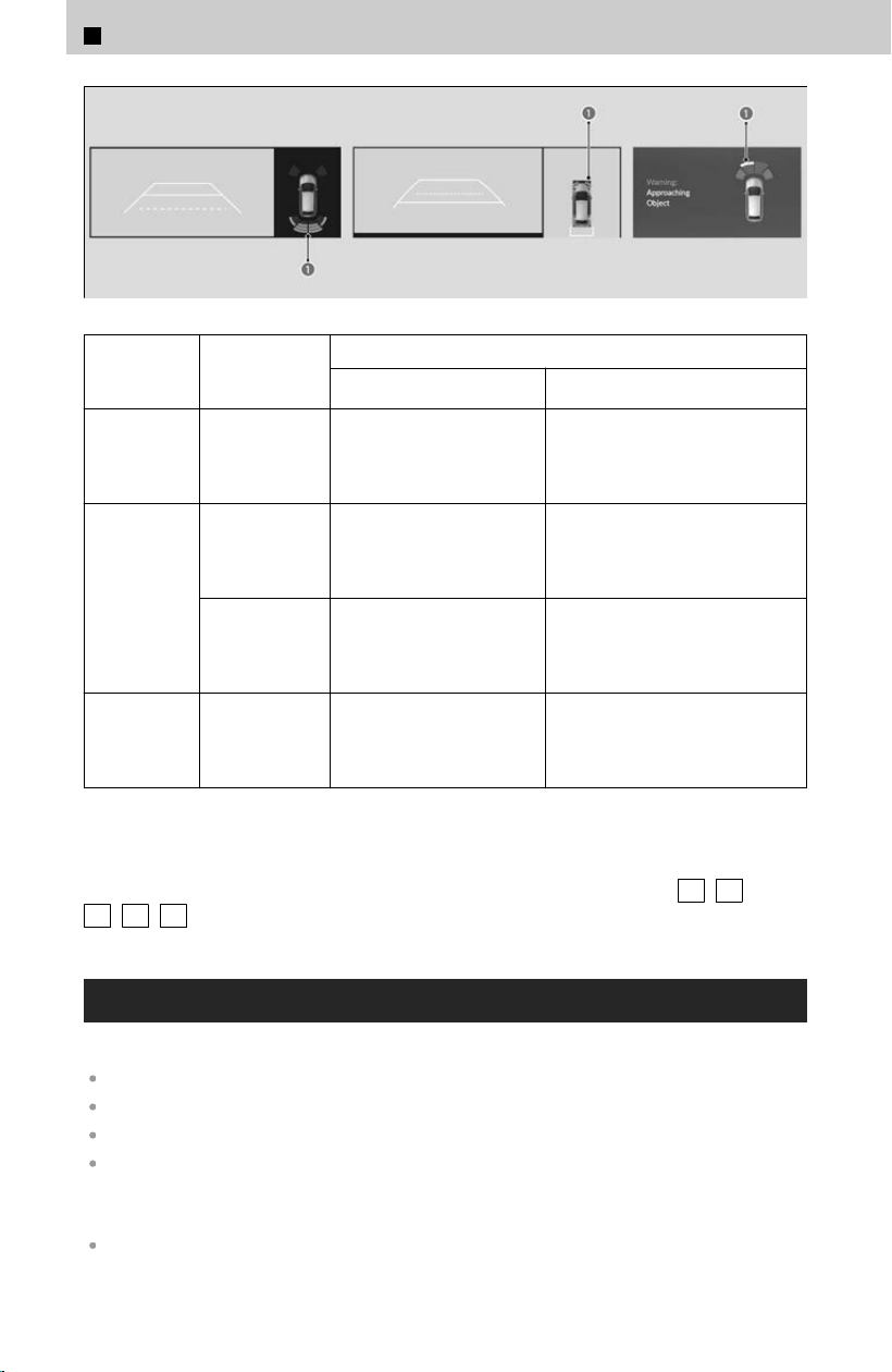
Color of
Indicator
Interval
between
beeps
Distance between the Bumper and Obstacle
Corner Sensors Center Sensors
Yellow
*1
Moderate —
Front: About 31-24 in (80-60
cm)
R
ear: About 43-29 in (110-73
cm)
Amber
Short
Front:
About 24-22 in (62-55 cm)
R
ear:
About 24-18 in (60-45 cm)
Front: About 24-20 in (60-50
cm)
Rear: About 29-23 in (73-58 cm)
Very short
Front:
About 22-18 in (55-45 cm)
R
ear:
About 18-14 in (45-35 cm)
Front: About 20-16 in (50-40
cm)
Rear: About 23-19 in (58-48 cm)
Red Continuous
Front:
About 18 in (45 cm) or les
s
Rear:
About 14 in (35 cm) or less
Front: About 16 in (40 cm) or
less
Rear: About 19 in (48 cm) or less
*1: When the indicator is yellow, only the center sensors detect obstacles.
To temporarily turn off the beeper, press the right selector wheel while it is sounding.
Temporary OFF will be canceled when the shift position changes from P
/ R to
N / D / S or vice-versa, or the vehicle speed reaches 9 mph (14 km/h) or higher.
Parking Sensor System Limitations
The system may not work properly when:
The sensors are covered with snow, ice, mud, or dirt.
The vehicle has been out in hot or cold weather.
There is something nearby that emits ultrasonic waves or high frequency sounds.
Driving in bad weather (rain, fog, snow, etc.).
The system may not detect these obstacles:
Thin or low objects.
4
Safety Driving Assist System > Parking Sensor System
320

Sonic-absorptive materials, such as snow, cotton, or sponge.
Objects directly under the bumper.
The system may falsely detect obstacles in the following situations:
The vehicle is on uneven surface, such as grass, bumps, or a hill.
When close to other vehicles with sonar sensors or other objects that emit ultrasonic waves.
There is splashing water near the sensors due to heavy rains, etc.
!
Do not put any accessories on or around the sensors.
If y
ou put any accessories (such as a towing hitch or bicycle rack) on or around
the rear sensors, the system may activate if it detects these accessories as an
obstacle. In this case, turn off the rear sensor.
Customized Features
u
P.239
4
Safety Driving Assist System > Parking Sensor System
321
4
Safety Driving Assist System

Indicators
Indicator List・・・・・・・・・・・・・・・・・・・・・・・・・・・・・・・・・・ 323
When Indicators Come On/Blink・・・・・・・・・・・・・・ 324
Gauges
Types of Gauges・・・・・・・・・・・・・・・・・・・・・・・・・・・・・・・ 330
Driver Information Interface
About the Driver Information Interface・・・・・・・・334
Driver Information Interface Right Side Area・・ 334
Driver Information Interface Left Side Area・・・ 341
About Your Instrument Panel
322
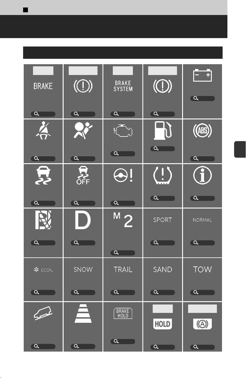
5
About Your Instrument Panel >
Indicators
Indicator List
4
U.S.
*1
Parking Brake and
Br
ake System
Indicator (Red)
P.325
4
Canada
*1
Parking Brake and
Br
ake System
Indicator (Red)
P.325
4
U.S.
*1
Parking Brake and
Br
ake System
Indicator (Amber)
P.325
4
Canada
*1
Parking Brake and
Br
ake System
Indicator (Amber)
P.325
*1
12-Volt Charging
System Indicator
P.326
Seat Belt
Reminder
Indicator
P.326
*1
Supplemental
Restraint System
Indicator
P.326
*1
Malfunction
Indicator Lamp
P.326
Low Fuel Indicator
P.327
*1
Anti-lock Brake
System (ABS)
Indicator
P.327
*1
Vehicle Stability
Assist™ (VSA®)
System Indicator
P.327
Vehicle Stability
Assist™ (VSA®)
OFF Indicator
P.327
*1
Electric Power
Steering (EPS)
System Indicator
P.327
*1
Low Tire Pressure/
TPMS Indicator
P.328
System Message
Indicator
P.341
Transmission
System Indicator
P.328
Gear Position
Indicator
P.115
M (sequential
mode) Indicator/
Gear Selection
Indicator
P.118
SPORT Mode
Indicator
P.159
NORMAL Mode
Indicator
P.159
ECON Mode
Indicator
P.159
SNOW Mode
Indicator
P.159
TRAIL Mode
Indicator
P.159
SAND Mode
Indicator
P.159
TOW Mode
Indicator
P.159
*1
Hill Descent
Control System
Indicator (White/
Green)
P.165
Adaptive Cruise
Control (ACC) with
Low Speed Follow
Interval Indicator
P.293
*1
Automatic Brake
Hold System
Indicator
P.124
4
U.S.
*1
Automatic Brake
Hold Indicat
or
P.124
4
Canada
*1
Automatic Brake
Hold Indicat
or
P.124
323
5
About Your Instrument Panel
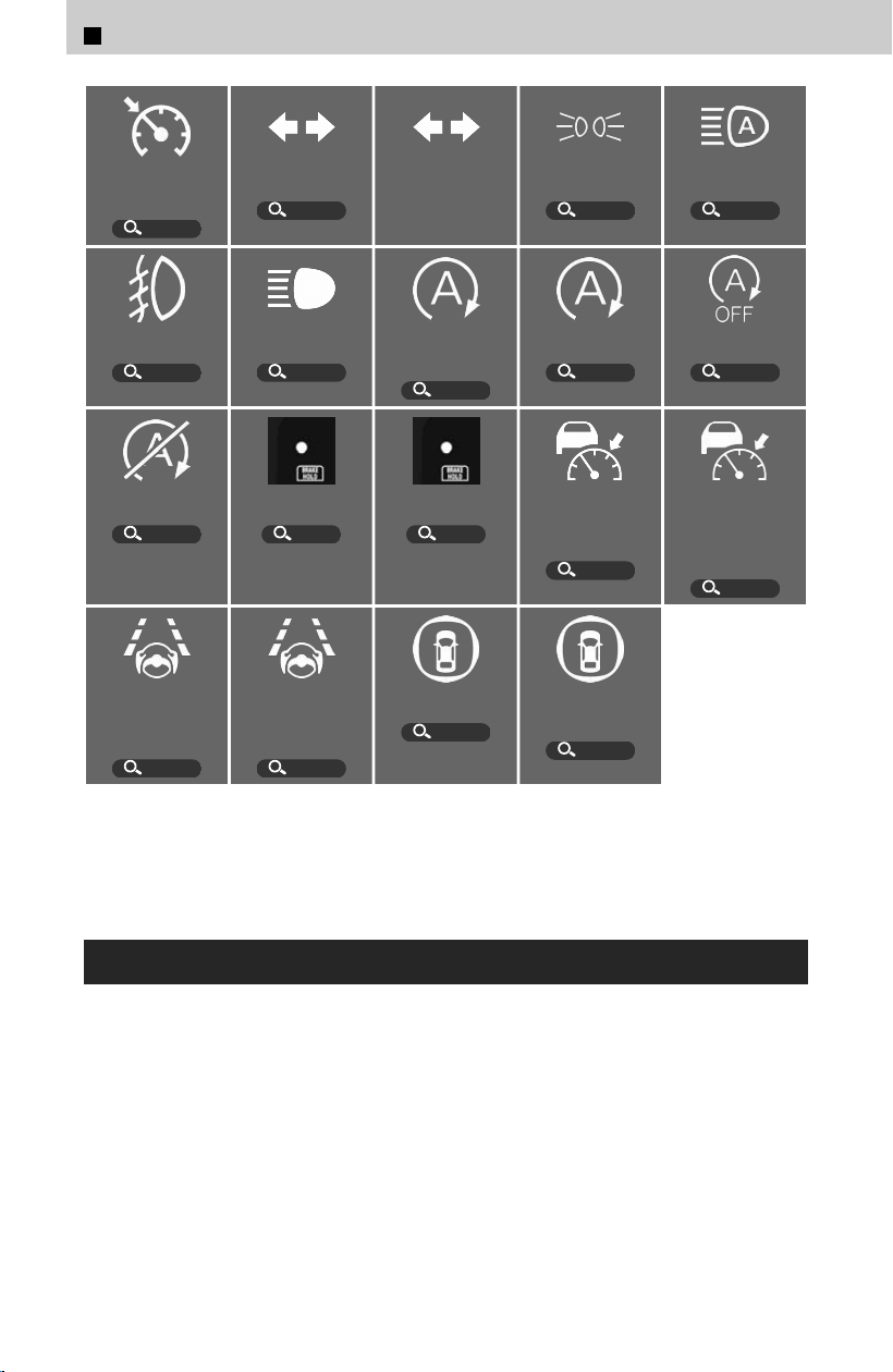
Cruise Mode
Indicator (White/
Green)
P.295
Turn Signal
Indicators
P.145
Hazard Warning
Indicators
Lights On
Indicator
P.145
*1
Auto High-Beam
Indicator
P.148
Fog Light
Indicator
*
P.148
High Beam
Indicator
P.147
*1
Auto Idle Stop
System Indicator
(Amber)
P.328
Auto Idle Stop
Indicator (Green)
P.161
Auto Idle Stop
OFF Indicator
P.162
Auto Idle Stop
Suspend Indicator
P.161
Immobilizer
System Indicator
P.48
Security System
Alarm Indicator
P.49
*1
Adaptive Cruise
Control (ACC) with
Low Speed Follow
Indicator (Amber)
P.328
Adaptive Cruise
Control (ACC) with
Low Speed Follow
Indicator (White/
Green)
P.268
*1
Lane Keeping
Assist System
(LKAS) Indicator
(Amber)
P.328
Lane Keeping
Assist System
(LKAS) Indicator
(White/Green)
P.268
*1
Safety Support
Indicator (Amber)
P.329
Safety Support
Indicator (Green/
Gray)
P.338
*1: When you set the power mode to ON, these indicators come on to indicate that system
checks are being performed. They go off a few seconds later or after the engine has started.
If an indicator does not come on or turn off, there may be a malfunction in the corresponding
system. To resolve the issue, follow the instructions in the owner’s manual.
When Indicators Come On/Blink
Indicators come on/blink depending on the condition of the vehicle. Messages may
be display
ed at the same time. Please take the appropriate action outlined in the
message, such as having your vehicle checked by a dealer.
If a message is displayed saying the vehicle cannot be driven, immediately stop in a
safe place and contact a dealer.
After reconnecting the 12-volt battery, if multiple indicators come on and Systems
initializing is displayed: with the engine running, turn the steering wheel to the left
until it stops then to the right until it stops, then drive a short distance at more than
12 mph (20 km/h). If the indicators do not go off, have your vehicle checked by a
dealer.
*: Not available on all models
5
About Your Instrument Panel > Indicators
324
4 U.S.
4 Canada
Parking Brake and Brake System Indicator (Red)
Comes on when the parking brake is applied, and goes off when it is released.
Comes on when the brake fluid level is low.
≫
Depress the brake pedal lightly to check pedal pressure.
≫
If normal, check the brake fluid level the next time you stop.
Checking the Brake Fluid
u
P.361
≫
If abnormal, take immediate action. If necessary, downshift the transmission to slow the
vehicle using engine braking.
Have your vehicle repaired immediately. It is dangerous to drive with low brake fluid. If there
is no resistance from the brake pedal, stop immediately in a safe place. If necessary,
downshift the gears.
Comes on if there is a problem with the brake system.
If the Parking Brake and Brake System Indicator (Red) and Parking Brake and Brake System
Indicator (Amber) come on simultaneously, the braking system may be less effective than
usual. Make sure to depress the brake pedal firmly. Immediately stop in a safe place and
contact a dealer.
If the Parking Brake and Brake System Indicator (Red) and ABS indicator come on
simultaneously, the electronic brake distribution system is not working. This can result in
vehicle instability under sudden braking. Have your vehicle inspected by a dealer
immediately.
Blinks if there is a problem with the electric parking brake.
≫
Do not use the parking brake.
≫
Put the transmission into P to prevent the vehicle from moving, as the parking brake may
not work.
If the Parking Brake and Brake System Indicator (Red) blinks at the same time when the
Parking Brake and Brake System Indicator (Amber) comes on, the parking brake may not
work. Avoid using the parking brake and have your vehicle checked by a dealer immediately.
4 U.S.
4 Canada
Parking Brake and Brake System Indicator
(Amber)
Comes on if there is a problem with a system related to braking other than the
conventional brake system.
Comes on if there is a problem with the electric parking brake system and/or the
automatic brake hold system.
≫
Do not use the parking brake.
Comes on if the vehicle is tilted due to heavy luggage in the cargo space or rear seats.
5
About Your Instrument Panel > Indicators
325
5
About Your Instrument Panel
12-Volt Battery Charging System Indicator
Comes on when there is a problem with the charging system.
Seat Belt Reminder Indicator
Comes on or blinks when any seat belts are unfastened.
≫
Securely fasten seat belts immediately.
Comes on or blinks when a seat belt in the rear seat is unfastened. Turns off momentarily.
If this indicator stays on after you and/or the passengers have fastened the seat belt(s), a
detection error may have occurred in the sensor. Have your vehicle checked by a dealer.
You can check whether each seat belt is fastened on the driver information interface.
Switching the Display
u
P.334
Supplemental Restraint System Indicator
Comes on if a problem with the airbag system or seat belt tensioners is detected.
About Your Airbags
u
P.32
Malfunction Indicator Lamp
After you set the power mode to ON, this indicator will turn on for a short time while
performing system checks. Immediately after, this indicator will blink several times if
the readiness codes are not set.
≫
Readiness codes are part of the on-board diagnostics for the emissions control systems.
Testing of Readiness Codes
u
P.422
Comes on if there is a problem with the engine’s emissions control systems.
If you drive with the malfunction indicator lamp on, the emissions control system and the
engine could be damaged.
Blinks when a mis
fire in the engine’s cylinders is detected.
≫
Park the vehicle in a safe place with no flammable items and wait at least 10 minutes or more
with the engine stopped until it cools.
5
About Your Instrument Panel > Indicators
326
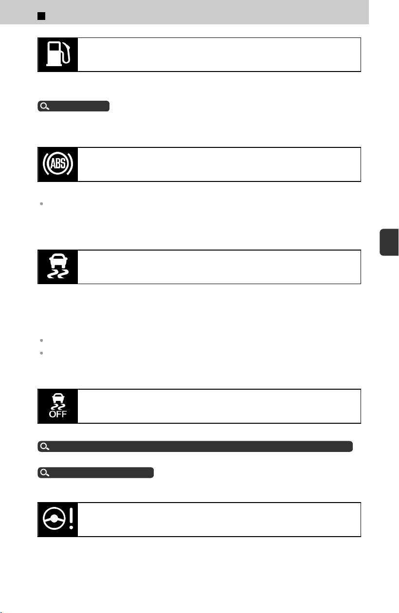
Low Fuel Indicator
Comes on when the fuel reserve is running low (approximately 2.77 U.S. gal/10.5
Liter left).
Range
u
P.334
Blinks if there is a problem with the fuel gauge.
Anti-lock Brake System (ABS) Indicator
Comes on if there is a problem with the ABS.
With this indicator on, your vehicle still has normal braking ability but no ABS function. This
can result in vehicle instability under sudden braking, so avoid situations such as highway
driving.
Vehicle Stability Assist™ (VSA®) System Indicator
Blinks when VSA®, or trailer stability assist is active.
Comes on if there is a problem with the VSA® system, brake assist system, hill start
assist system, starting assist brake function, agile handling assist, or trailer stability
assist.
With this indicator on, your vehicle still has normal braking ability.
When Trailer stability assist system problem is displayed on the driver information
interface, the VSA® does not activate.
Vehicle Stability Assist™ (VSA®) OFF Indicator
Comes on when you partially disable VSA®.
Vehicle Stability Assist™ (VSA®), aka Electronic Stability Control (ESC), System
u
P.166
Comes on in TRAIL and SAND driv
e modes.
Drive Mode System
u
P.159
Electric Power Steering (EPS) System Indicator
Comes on if there is a problem with the EPS system.
5
About Your Instrument Panel > Indicators
327
5
About Your Instrument Panel
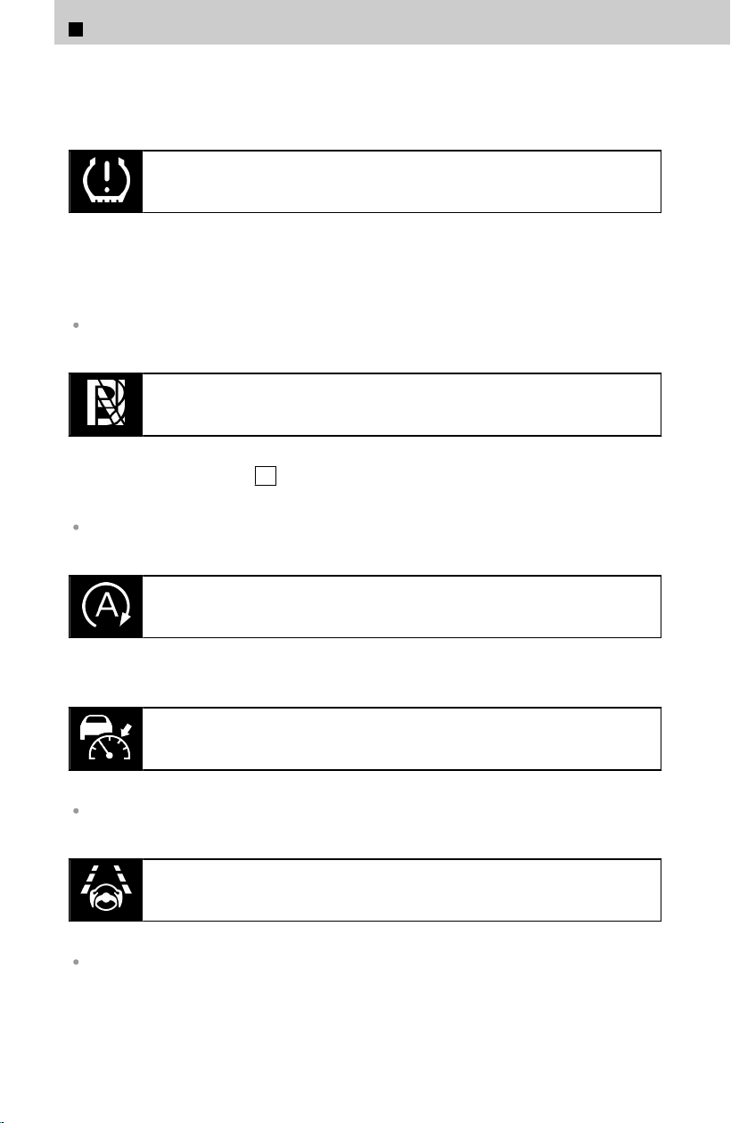
≫
Stop your vehicle in a safe place. If this indicator stays on after restarting the engine, take your
vehicle to a dealer for an inspection immediately.
Low Tire Pressure/TPMS Indicator
Comes on if the tire pressure of any of the tires becomes low.
≫
Stop in a safe place, check tire pressures, and inflate the tire(s) if necessary.
If this indicator stays on after blinking, there is a problem with the TPMS with Tire Fill
As
sist.
This indicator also comes on when a compact spare tire is installed.
Transmission System Indicator
Blinks if the transmission system has a problem.
Blinks if you cannot select P due to a transmission system failure.
≫
Set the parking brake when parking.
Depending on the situation, you may not be able to start the engine.
Auto Idle Stop System Indicator (Amber)
Blinks if there is a problem with the Auto Idle Stop system.
Adaptive Cruise Control (ACC) with Low Speed Follow
Indicator (Amber)
Comes on if there is a problem with ACC with Low Speed Follow.
Comes on if the vehicle is tilted due to heavy luggage in the cargo space or rear seats.
Lane Keeping Assist System (LKAS) Indicator (Amber)
Comes on if there is a problem with the LKAS.
Comes on if the vehicle is tilted due to heavy luggage in the cargo space or rear seats.
5
About Your Instrument Panel > Indicators
328
Safety Support Indicator (Amber)
Comes on if there is a problem with any of the safety support systems.
Safety Support
u
P.338
Comes on if the vehicle is tilted due to heavy luggage in the cargo space or rear seats.
Comes on if there is a problem with the parking sensor.
≫
Check if the area around the sensor(s) is covered with mud, ice, snow, etc.
About Parking Sensor System
u
P.318
Comes on when driver assist system functions are limited because the radar sensor is
c
overed with obstacles such as dirt.
Radar Sensor
u
P.271
Comes on when driver assist system functions are limited because the camera’s
t
emperature is too high.
Front Sensor Camera
u
P.270
Comes on when driver assist system functions are limited because of poor camera
visibilit
y due to poor weather such as rain, fog, snow; or due to dark surroundings
such as in early morning, late evening, or the inside of a tunnel at night.
Comes on when the area around the camera is covered by obstacles.
Front Sensor Camera
u
P.270
Comes on when the blind spot information system’s sensor is dirty.
≫
Park in a safe place and check the vicinity of the blind spot information system sensor and
remove any obstacles.
About Blind Spot Information System
u
P.311
Comes on when the temperature of the blind spot information system sensor is high.
≫
The system will return to normal when the temperature cools down
Comes on when the Low Speed Braking Control System’s functions are limited
because the sonar sensor is c
overed by obstacles.
Sonar Sensors
u
P.272
About Low Speed Braking Control
u
P.280
5
About Your Instrument Panel > Indicators
329
5
About Your Instrument Panel
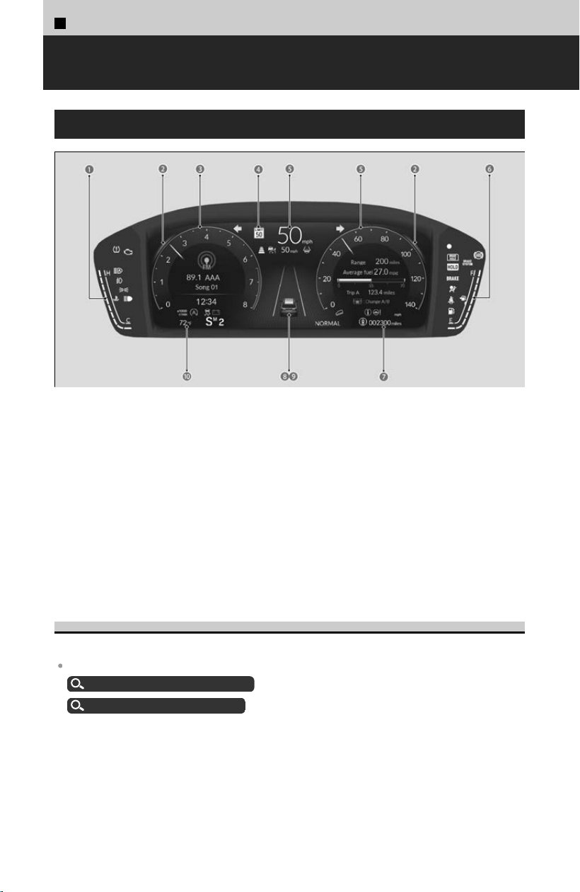
5
About Your Instrument Panel >
Gauges
Types of Gauges
a Temperature Gauge
b Ambient Meter
c Tachometer
d Traffic Sign Recognition System
e Speedometer
f Fuel Gauge
g Odometer
h Current Mode for Adaptive Cruise Control (ACC) with Low Speed Follow, the
Lane Keeping Assist System (LKAS), and Traffic Jam Assist
i Parking Sensor System
j Outside Temperature
Speedometer
Displays your driving speed.
You can change the Speed/Distance units.
Gauge Display Settings
u
P.340
Customized Features
u
P.239
330
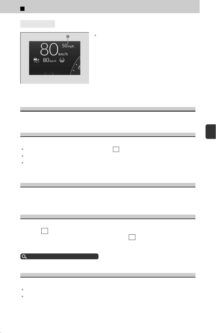
4
U.S. models
a Vehicle Speed in mph
If you change the unit from miles and mph to km and
km/h, the current vehicle speed in mph appears next
to the digital speedometer.
Tachometer
Shows the number of engine revolutions per minute.
Fuel Gauge
Displays the amount of fuel left in the fuel tank.
You should refuel when the reading approaches E .
Running out of fuel can cause the engine to misfire, damaging the catalytic converter.
After lightly refueling, or depending on your vehicle’s condition, the actual amount of
remaining fuel may differ from the fuel gauge reading.
Ambient Meter
Changes to green to indicate that the vehicle is being driven in a fuel
-efficient manner
with SPORT mode off.
Temperature Gauge
Displays the temperature of the engine coolant. Normally, the reading should not
r
each the H mark while driving.
Driving with the temperature gauge reading near the H can cause serious engine
damage. Pull safely to the side of the road and allow engine temperature to return to
normal.
How to Handle Overheating
u
P.399
Outside Temperature
Shows the outside temperature.
The temperature sensor is in the front bumper.
Your vehicle, surrounding vehicles, and road heat can affect the temperature reading when
your vehicle speed is less than 19 mph (30 km/h). Also, the display is not updated until the
temperature reading has stabilized. This may take several minutes.
5
About Your Instrument Panel > Gauges
331
5
About Your Instrument Panel
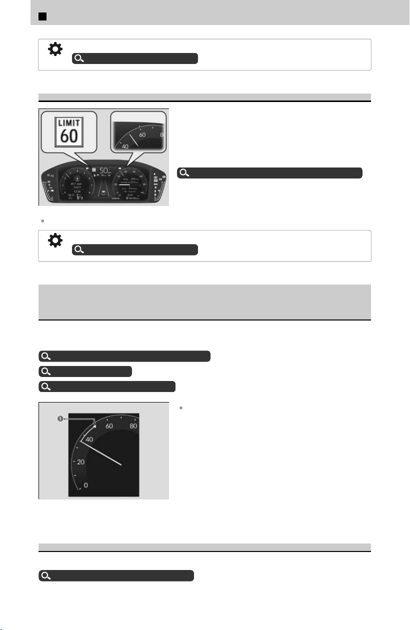
You can adjust the temperature displayed on the gauge.
Customized Features
u
P.239
Traffic Sign Recognition System
Shows certain detected traffic signs while driving.
If speed limit warning is activated, the sign icon
blinks when the maximum speed of the traffic
sign detected is exceeded by a threshold, when
compared with the vehicle speed.
About Traffic Sign Recognition System
u
P.308
The default speed limit warning threshold is the maximum speed of the traffic sign detected.
You can adjust the threshold for speed limit warning.
Customized Features
u
P.239
Current Mode for Adaptive Cruise Control (ACC) with Low
Speed Follow, the Lane Keeping Assist System (LKAS), and
Traffic Jam Assist
Shows the current mode for ACC with Low Speed Follow, LKAS, and T
raffic Jam
Assist.
About ACC with Low Speed Follow
u
P.289
About LKAS
u
P.300
About Traffic Jam Assist
u
P.304
a Set Speed
When you set speed for ACC with Low Speed Follow
or cruise control, a set speed mark will be displayed
on the speedometer.
Parking Sensor System
Shows information about the parking sensor system.
About Parking Sensor System
u
P.318
5
About Your Instrument Panel > Gauges
332

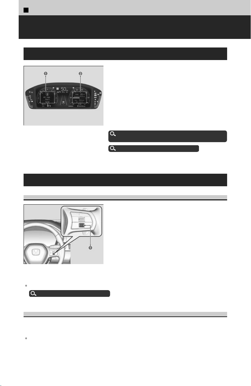
5
About Your Instrument Panel >
Driver Information Interface
About the Driver Information Interface
a Driver Information Interface
Left Side Area
b Driver Information Interface
Right Side Area
The driver information interface shows your
v
ehicle’s condition and alerts you with a warning
message when an abnormality is detected.
When a warning message displays, please check
the message and contact a dealer to have the
vehicle inspected if necessary.
Please refer to the pages below if the Engine oil
pressure low or Engine temperature too hot
message is displayed.
If the Engine oil pressure low Warning Appears
u
P.401
How to Handle Overheating
u
P.399
Driver Information Interface Right Side Area
Switching the Display
a Right Selector Wheel
Roll the right selector wheel to view different
t
ypes of content.
You can add or delete the meter contents.
Gauge Display Settings
u
P.340
Range
Shows the estimated distance you can travel on the remaining fuel. This estimated
dis
tance is based on the vehicle’s current fuel economy.
The driving range displayed is only an estimate and may differ from the actual distance the
vehicle can travel.
334
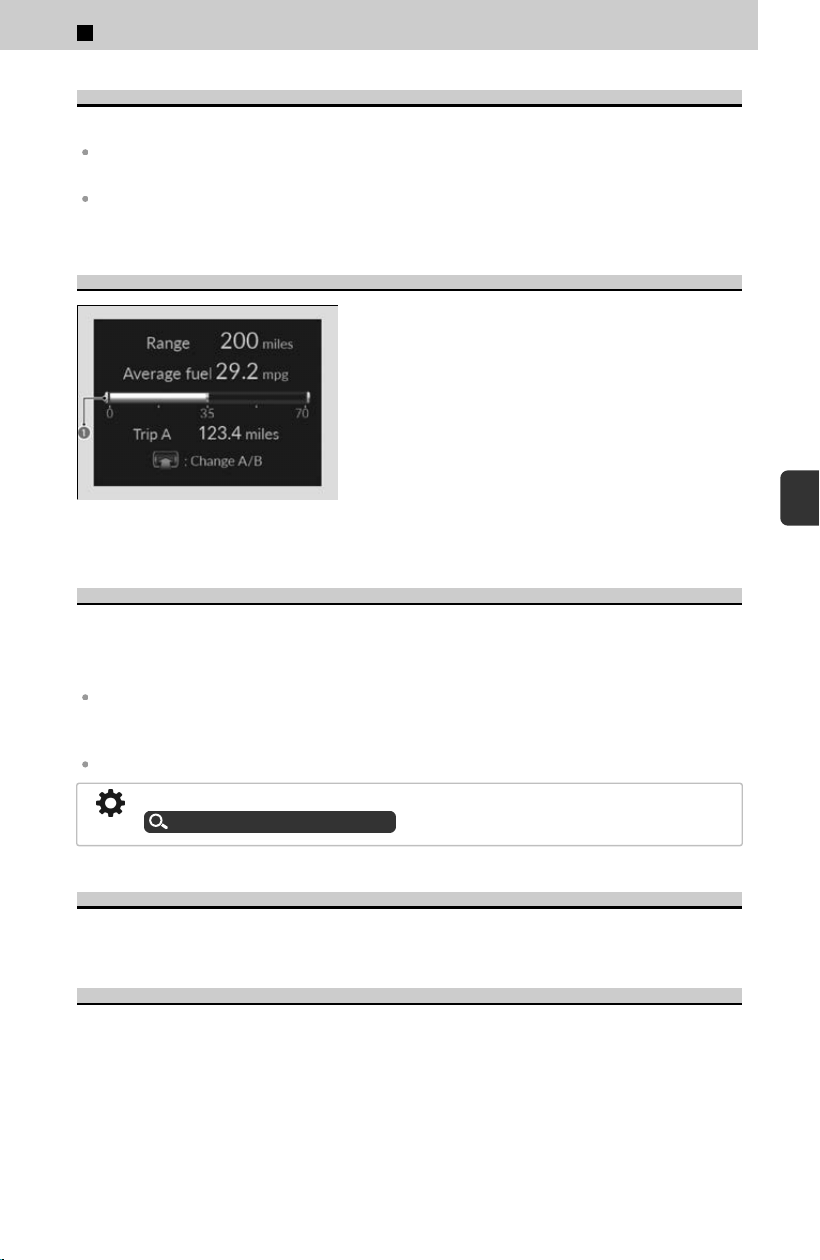
Average Fuel Economy
Shows the average fuel economy for trip meters A and B in set intervals.
The average fuel economy displayed may differ from the amount consumed while actually
driving.
If it was reset while parked or driving at a low speed, calculation of fuel consumption will start
after you resume normal driving.
Instant Fuel Economy
a Instant Fuel Economy
Shows the instant fuel economy as a bar graph.
Trip Meter
Shows the total distance driven since the last reset. Press the right selector wheel to
s
witch between trip meter A and trip meter B. Meters A and B can be used to
measure two separate trips.
To reset the trip meter, display it, press and hold the right selector wheel, and then select
Reset. The trip meter is reset to 0.0. Additionally, average fuel economy, average speed, and
elapsed time will also be reset.
When the trip meter exceeds 9999.9 miles or kilometers, it resets to 0.0.
The trip meter can reset automatically after refueling.
Customized Features
u
P.239
Average Speed
Shows the average speed since Trip A or Trip B was reset.
Elapsed Time
Shows the time elapsed since Trip A or Trip B was reset.
5
About Your Instrument Panel > Driver Information Interface
335
5
About Your Instrument Panel
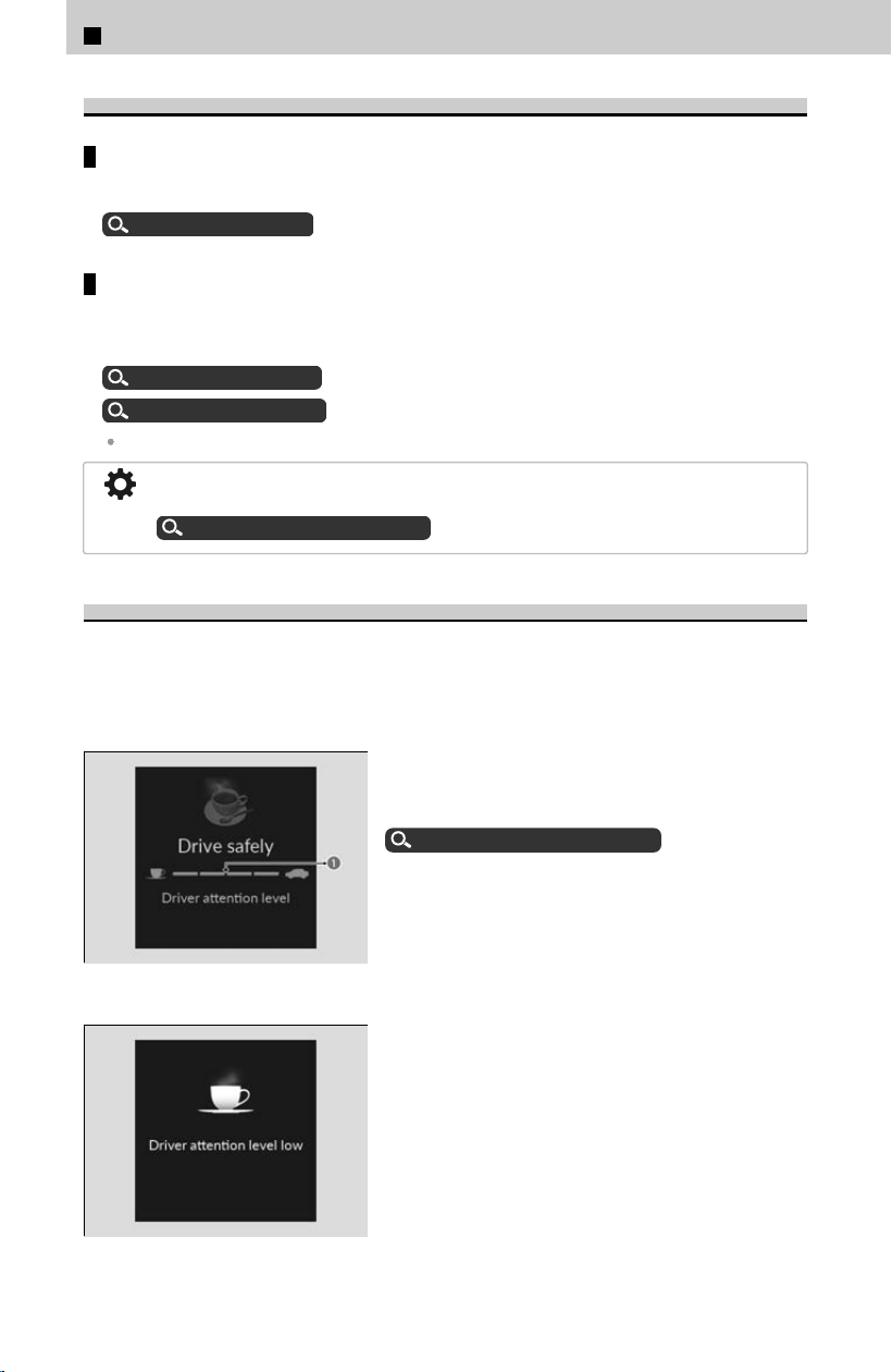
Navigation
Maps
Shows Google Maps screen.
Google Maps
u
P.232
Compass/Turn-by-Turn Direction
The compass screen and turn-by-turn directions appear based on the driving
g
uidance provided by Apple CarPlay or Android Auto.
Apple CarPlay
u
P.225
Android Auto™
u
P.228
Navigation features may not be available for all devices or apps.
You can select whether to have the turn-by-turn display come on or not during the
route guidance.
Customized Features
u
P.239
Driver Attention Monitor
The Driver Attention Monitor analyzes steering inputs to determine if the vehicle is
being driv
en in a manner consistent with drowsy or inattentive driving. If it
determines that the vehicle is being driven in such a manner, it will display the degree
of the driver’s attention on the driver information interface.
a Level
When you select Driv
er attention on the driver
information interface, bars on it light up in white
to indicate the degree of the driver’s attention.
Switching the Display
u
P.334
If two bars light up, the Driver attention level
low message will appear.
5
About Your Instrument Panel > Driver Information Interface
336
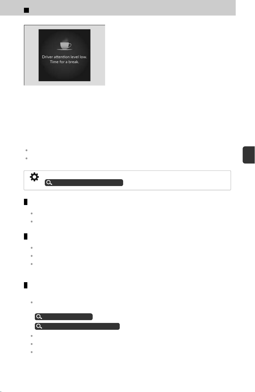
If one bar lights up, the Driver attention level
low. Time for a break. message will appear, a
beep will sound, and the steering wheel will
vibrate.
If this message appears, stop in a safe location
and rest for as long as needed.
The message will disappear when the right
selector wheel is rolled or when the system has
determined that the driver is driving normally.
If the driver does not take a break and the
monitor continues to detect that the driver is very
tired, the message will appear again after
approximately 15 minutes, accompanied by a
beep and steering wheel vibrations.
The message does not appear when the traveling
time is 30 minutes or less.
The Driver Attention Monitor cannot always detect if the driver is tired or inattentive.
Regardless of the system’s feedback, if you are feeling tired, stop in a safe location and rest
for as long as needed.
You can change the system settings.
Customized Features
u
P.239
The Driver Attention Monitor resets when:
The engine is turned off.
The driver unfastens the seat belt and opens the door while the vehicle is stopped.
For the Driver Attention Monitor to function:
The vehicle must be traveling above 25 mph (40 km/h).
The electric power steering (EPS) system indicator must be off.
The bars on the driver information interface remain grayed-out unless the Driver Attention
Monitor is functioning.
Depending on driving conditions or other factors, the Driver Attention
Monitor may not function in the following circumstances:
The steering assist function of the Lane Keeping Assist System (LKAS) or Traffic Jam Assist
is active.
About LKAS
u
P.300
About Traffic Jam Assist
u
P.304
The condition of the road is poor; e.g., the surface is unpaved or bumpy.
It is windy.
The driver is frequently operating the vehicle in an assertive manner, such as changing
lanes or accelerating.
5
About Your Instrument Panel > Driver Information Interface
337
5
About Your Instrument Panel
AWD Torque Distribution Monitor
The indicators on the display show the amount of torque being transferred to the right
fr
ont, left front, right rear, and left rear wheels.
Intelligent Variable Torque Management (i-VTM4™) AWD System
u
P.168
Pitch and Roll
Shows the pitch and roll status.
This Pitch/Roll gauge is intended for reference when the vehicle is not moving. If the vehicle
is moving, G inputs will affect the accuracy of the displayed angle.
This display will automatically be shown when the TRAIL mode is selected. It is also user
selectable when in any drive mode.
Drive Mode System
u
P.159
Seat Belts
Occurs, under specified c
onditions, when seat belts are latched or unlatched.
Seat Belt Reminder
u
P.74
Maintenance
Shows the remaining oil life and Maintenance Minder™.
About Maintenance Minder™
u
P.348
Tire Pressure Monitor
Shows each tire’s pressure.
Tire Pressure Monitoring System (TPMS) with Tire Fill Assist
u
P.169
Safety Support
Safety Support indicates the operating status of the following systems.
5
About Your Instrument Panel > Driver Information Interface
338
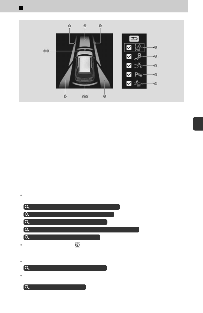
a Operating Status for Road Departure Mitigation System
b Operating Status for CMBS™
c Operating Status for Low Speed Braking Control
d Operating Status for Parking Sensor System
e Operating Status for Blind Spot Information System
f Road Departure Mitigation System
g Blind Spot Information System
h Low Speed Braking Control
i Parking Sensor System
j CMBS™
The following colors indicate the status of any of the above-mentioned systems:
- Green: The system is on.
- Gray: The system is off.
- Amber: There is a problem with the system.
To turn each system on or off, first press the right selector wheel to switch displays. From the
next display, you can select which system to turn on or off.
About Road Departure Mitigation System
u
P.285
About Blind Spot Information System
u
P.311
About Low Speed Braking Control
u
P.280
About Collision Mitigation Braking System™(CMBS™)
u
P.274
About Parking Sensor System
u
P.318
When all features are ON, the safety support indicator lights up in green. It lights up in
green/gray when one or some of the features are ON, and it lights up in gray when all features
are OFF.
See below if the indicator lights up in amber.
Safety Support Indicator (Amber)
u
P.329
Even when the Low Speed Braking Control icon is green, if the Rear Sensor Setting is turned
off, the brake assist will not operate when reversing.
Customized Features
u
P.239
5
About Your Instrument Panel > Driver Information Interface
339
5
About Your Instrument Panel

Even when the parking sensor system icon is green, if the Rear Sensor Setting is turned off,
the rear parking sensor will not operate when reversing.
Customized Features
u
P.239
Brightness Setting
Display the adjustment for instrument panel brightness.
When the power mode is in ON, you can use the right selector wheel to adjust
ins
trument panel brightness.
Brighten: Roll the right selector wheel up.
Dim: Roll the right selector wheel down.
Press the right selector wheel to exit.
The brightness of the gauge is automatically adjusted depending on the ambient brightness.
≫
The brightness decreases when the ambient light is dark.
≫
The brightness increases when the ambient light is bright.
You can change the setting even when the ambient lighting is bright, but the brightness of the
gauge won’t change.
Vehicle Stability Assist Mode
You can turn the VSA® on or off.
Roll the right selector wheel to scroll to select R
educe traction control, then press
the right selector wheel to check or uncheck it.
Vehicle Stability Assist™ (VSA®), aka Electronic Stability Control (ESC), System
u
P.166
Gauge Display Settings
Speed/distance units
Enables you to set the displayed measurements to read in either miles and mph or
km and km
/h.
[1] Press the right selector wheel when you select the Gaug
e display settings on
the driver information interface.
[2] Roll the right selector wheel to scroll to select Speed/distance units, then
press the right selector wheel.
[3] Roll the right selector wheel to scroll to select your desired settings, then
press the right selector wheel.
Arrange content on the right side area
You can choose which contents to display on the right side area.
[1] Press the right selector wheel when you select the Gaug
e display settingson
the driver information interface.
[2] Roll the right selector wheel to scroll to select Hide/show, then press the right
selector wheel.
5
About Your Instrument Panel > Driver Information Interface
340
[3] Roll the right selector wheel to scroll between contents, then press the right
selector wheel to check or uncheck them.
Contents that are gray cannot be removed from the right side area.
When you customize settings, shift to P .
Change gauge design
You can change the gauge design.
[1] Press the right selector wheel when you select the Gaug
e display settings on
the driver information interface.
[2] Roll the right selector wheel to scroll to select Gauge design, then press the
right selector wheel.
[3] Roll the right selector wheel to scroll to select your desired settings, then
press the right selector wheel.
When using the Round minimal or Bar minimal gauge design, a simplified display is used
when ACC with Low Speed Follow is in operation.
Warnings
You can check if there are any active warning messages.
If there are multiple warnings, you can roll the right selector wheel to see other warnings.
When there is a warning message, the system message indicator lights up.
Driver Information Interface Left Side Area
Shows the current mode for audio and phone information, etc.
Audio Remote Controls
u
P.203
Bluetooth® HandsFreeLink®
u
P.234
Clock
Shows the clock.
You can choose whether the clock is displayed on the driver information interface.
Customize Display
u
P.342
Clock Setup
Manual time adjustment is not necessary because the clock is using satellite
inf
ormation. For details on other settings, please refer to the Navigation or Audio
instruction manuals for your vehicle.
5
About Your Instrument Panel > Driver Information Interface
341
5
About Your Instrument Panel
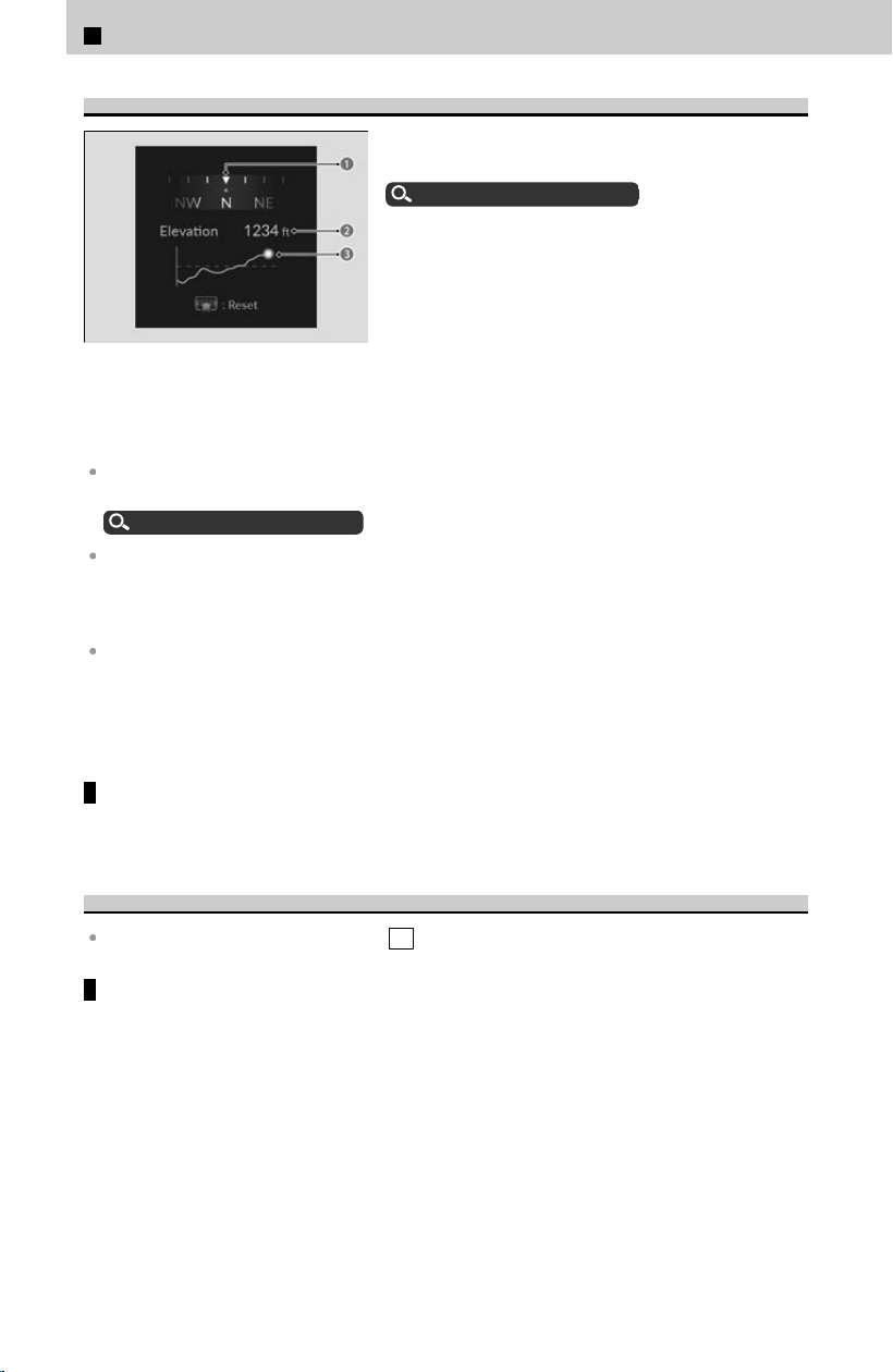
Elevation and Compass
a Compass
b Elevation
c Elevation History
Select Ele
vation and compass on the customize
display to show elevation and the compass.
Customize Display
u
P.342
This display will automatically be shown when the TRAIL mode is selected. It is also user
selectable when in any drive mode.
Drive Mode System
u
P.159
This feature uses information from GPS satellite signals, so it requires open skies for the best
accuracy. If used when in cities or around large/tall objects, the signal may not be sufficient to
display an accurate Elevation. In these situations, the display will not show an elevation value
and will instead show -----. Elevation History will also not be displayed.
Elevation history is shown for the previous 10 miles (16 km) of driving (x-axis). Once you drive
further than 10 miles (16 km), the display shows a scrolling history of the past 10 miles (16
km). The Y-axis represents the elevation. This starts with a scale of +/-200 feet (61 meters)
from your current elevation. As you go beyond that, the elevation scale will adjust to continue
to show all your data.
Reset Elevation History
Press the left selector wheel, and then select R
eset.
Customize Display
When you customize settings, shift to P .
Arrange audio source on the left side area
You can choose which sources to display on the audio source screen.
[1] Roll the left selector wheel until Cus
tomize display is selected, then press the
left selector wheel.
[2] Roll the left selector wheel to scroll to select Hide/show, then press the left
selector wheel.
[3] Roll the left selector wheel to scroll between audio sources, then press the left
selector wheel to check or uncheck them.
5
About Your Instrument Panel > Driver Information Interface
342

Select the display content on the left side area
You can change the display content on the left side area. Select Audio & clock,
Ele
vation and compass, or OFF.
[1] Roll the left selector wheel until Cus
tomize display is selected, then press the
left selector wheel.
[2] Roll the left selector wheel to scroll to select Display content, then press the
left selector wheel.
[3] Roll the left selector wheel to scroll to select your desired content, then press
the left selector wheel.
5
About Your Instrument Panel > Driver Information Interface
343
5
About Your Instrument Panel

Before Performing Maintenance
Inspection and Maintenance・・・・・・・・・・・・・・・・・・ 345
Maintenance Safety・・・・・・・・・・・・・・・・・・・・・・・・・・・ 346
Vehicle Safety・・・・・・・・・・・・・・・・・・・・・・・・・・・・・・・・・ 346
Maintenance Minder™
About Maintenance Minder™・・・・・・・・・・・・・・・・・・ 348
To Use Maintenance Minder™・・・・・・・・・・・・・・・・・ 348
Maintenance Under the Hood
Maintenance Items Under the Hood・・・・・・・・・・・353
Opening the Hood・・・・・・・・・・・・・・・・・・・・・・・・・・・・・ 353
Recommended Engine Oil・・・・・・・・・・・・・・・・・・・・・ 354
Oil Check・・・・・・・・・・・・・・・・・・・・・・・・・・・・・・・・・・・・・・ 355
Adding Engine Oil・・・・・・・・・・・・・・・・・・・・・・・・・・・・・・356
Changing the Engine Oil and Oil Filter・・・・・・・・・ 357
Engine Coolant・・・・・・・・・・・・・・・・・・・・・・・・・・・・・・・・ 358
Transmission Fluid・・・・・・・・・・・・・・・・・・・・・・・・・・・・・360
Brake Fluid・・・・・・・・・・・・・・・・・・・・・・・・・・・・・・・・・・・・ 361
Refilling Window Washer Fluid・・・・・・・・・・・・・・・・ 361
Checking and Maintaining Wiper
Blades
Lifting the Front Wiper Arms・・・・・・・・・・・・・・・・・・・363
Changing the Front Wiper Blade Rubber・・・・・・・363
Changing the Rear Wiper Blade Rubber・・・・・・・ 365
Checking and Maintaining Tires
Checking Tires・・・・・・・・・・・・・・・・・・・・・・・・・・・・・・・・・ 367
Tire Fill Assist・・・・・・・・・・・・・・・・・・・・・・・・・・・・・・・・・ 368
Tire and Loading Information Label・・・・・・・・・・・ 368
Tire Labeling・・・・・・・・・・・・・・・・・・・・・・・・・・・・・・・・・・・369
DOT Tire Quality Grading (U.S. Vehicles)・・・・・・・370
Wear Indicators・・・・・・・・・・・・・・・・・・・・・・・・・・・・・・・ 372
Tire Service Life・・・・・・・・・・・・・・・・・・・・・・・・・・・・・・・ 372
Tire and Wheel Replacement・・・・・・・・・・・・・・・・・・ 373
Winter Tires・・・・・・・・・・・・・・・・・・・・・・・・・・・・・・・・・・・ 373
Tire Rotation・・・・・・・・・・・・・・・・・・・・・・・・・・・・・・・・・・・374
12-Volt Battery
Maintaining 12-Volt Battery・・・・・・・・・・・・・・・・・・・ 376
Checking the 12-Volt Battery・・・・・・・・・・・・・・・・・・ 377
Charging the AGM Battery・・・・・・・・・・・・・・・・・・・・・ 377
Climate Control System Maintenance
Air Conditioning・・・・・・・・・・・・・・・・・・・・・・・・・・・・・・・ 378
Cleaning
Int
erior Care・・・・・・・・・・・・・・・・・・・・・・・・・・・・・・・・・・・ 379
Exterior Care・・・・・・・・・・・・・・・・・・・・・・・・・・・・・・・・・・・380
Maintenance
344

6
Maintenance >
Before Performing Maintenance
Inspection and Maintenance
For your safety, perform all listed inspections and maintenance to keep your vehicle in
g
ood condition.
If you become aware of any abnormality (noise, smell, insufficient brake fluid, oil
residue on the ground, etc.), have your vehicle inspected by a dealer. (Note, however,
that service at a dealer is not mandatory to keep your warranties in effect.)
Periodic inspections
Check the brake fluid level monthly.
Brake Fluid
u
P.361
Check the tire pressure monthly. Examine the tread for wear and foreign objects.
Checking Tires
u
P.367
Check the operation of the exterior lights monthly.
About the Vehicle’s LED Exterior Lighting
u
P.385
Replacing Light Bulbs
u
P.385
Check the condition of the wiper blades at least every six months.
Changing the Front Wiper Blade Rubber
u
P.363
Changing the Rear Wiper Blade Rubber
u
P.365
Routine inspections
Perform inspections before long distance trips, when washing the vehicle, or when
r
efueling.
4
U.S. models
Maintenance, replacement, or repair of emissions control devices and systems
may be done b
y any automotive repair establishment or individuals using
parts that are “certified” to EPA standards.
According to state and federal regulations, failure to perform maintenance on the
maintenance main items marked with # will not void your emissions warranties.
However, all maintenance services should be performed in accordance with the
intervals indicated by the driver information interface.
Maintenance Service Items
u
P.350
If you want to perform complex maintenance tasks that require more skills and
t
ools, you can purchase a subscription to the Service Express website at https://
techinfo.honda.com.
345
6
Maintenance

If necessary
u
P.426
If you want to perform maintenance yourself, make sure that you have the
nec
essary tools and skills first. After performing maintenance, update the records
in the separate maintenance booklet.
3 WARNING
Improperly maintaining this vehicle or failing to correct a problem before
driving can cause a cr
ash in which you or a passenger can be seriously hurt
or killed.
Always follow the inspection and maintenance recommendations according
to the schedules in this owner’s manual.
3 WARNING
Failure to properly follow maintenance instructions and precautions can
cause y
ou or a passenger to be seriously hurt or killed.
Always follow the procedures and precautions in this owner's manual.
Maintenance Safety
To reduce the possibility of fire or explosion, keep cigarettes, sparks, and flames away from
the 12-volt battery and all fuel related parts.
Never leave rags, towels, or other flammable objects under the hood.
≫
Heat from the surrounding parts can ignite them, causing a fire.
Engine exhaust contains carbon monoxide, which is poisonous and can kill you.
≫
Only operate the engine if there is sufficient ventilation.
To clean parts, use a commercially available degreaser or parts cleaner, not gasoline.
Wear eye protection and protective clothing when working with the 12-volt battery or
compressed air.
Vehicle Safety
The vehicle must be stationary.
≫
Make sure your vehicle is parked on level ground, the parking brake is set, and the engine is
off.
Make sure that the radiator fan is stopped before inspecting the engine compartment.
≫
Depending on the vehicle condition, the radiator fan may operate even when the power
mode is in VEHICLE OFF.
Be aware that hot parts can burn you.
≫
Make sure to let the engine and exhaust system cool thoroughly before touching vehicle
parts.
6
Maintenance > Before Performing Maintenance
346

Be aware that moving parts can injure you.
≫
Do not start the engine unless instructed, and keep your hands and limbs away from
moving parts.
≫
Do not open the hood while the Auto Idle Stop function is activated.
The use of Honda Genuine Parts and fluids is recommended when maintaining and servicing
your vehicle. Honda Genuine Parts are manufactured according to the same high quality
standards used in Honda vehicles.
!
Do not press the engine cover forcibly. This may damage the engine
c
over and component parts.
6
Maintenance > Before Performing Maintenance
347
6
Maintenance
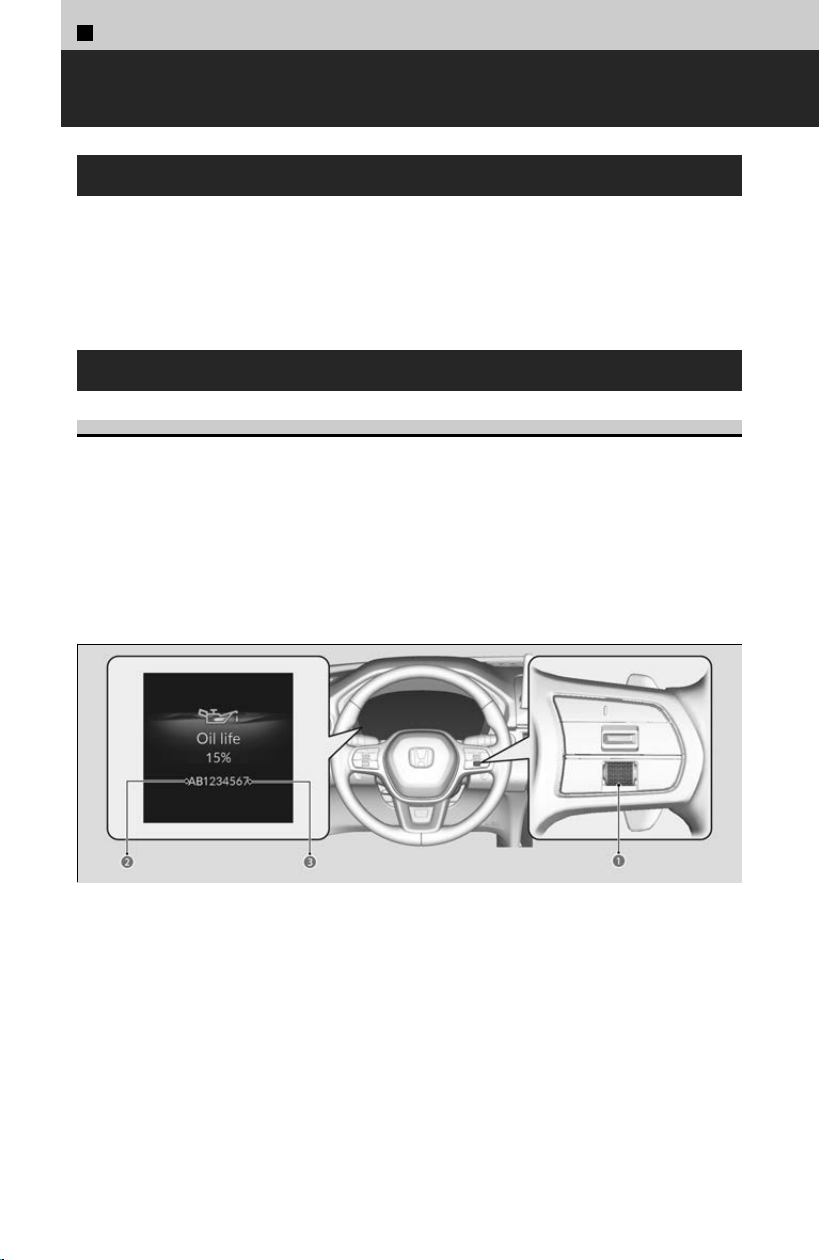
6
Maintenance >
Maintenance Minder™
About Maintenance Minder™
If the engine oil life is less than 15%, you will see the Maintenance Minder messages
appear on the driv
er information interface every time you set the power mode to ON.
The messages notify you when to change the engine oil, or when to bring your vehicle
to a dealer for indicated maintenance services.
To Use Maintenance Minder™
Displaying the Maintenance Minder Information
Maintenance items, which should be serviced at the same time that you replace the
engine oil
, appear on the driver information interface. You can view them on the
engine oil life screen at any time.
[1] Set the power mode to ON.
[
2] Roll the right selector wheel until the Maintenance Minder screen is displayed.
The engine oil life appears on the driver information interface along with
maintenance items due soon.
a Right Selector Wheel
b Main Item
c Sub Item
Based on the engine operating conditions, the remaining engine oil life is calculated
and display
ed as a percentage.
348
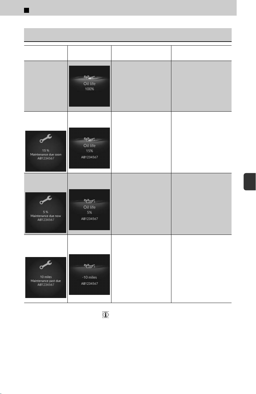
Maintenance Minder Messages on the Driver Information
Interface
Maintenance
Message
Oil Life Display Explanation Information
-
When you select the
Maintenance Minder
screen, it displays codes
for maintenance items
due at the next engine oil
change, along with the
percentage of engine oil
life remaining.
-
Maintenance due
soon
15 %
The remaining engine oil
life is 15 to 6 percent.
Roll the right selector
wheel to switch to another
display.
The engine oil is
approaching the end of its
service life, and the
maintenance items should
be inspected and serviced
soon.
Maintenance due
no
w
5 %
The remaining engine oil
life is 5 to 1 percent.
Roll the right selector
wheel to switch to another
display.
The engine oil has almost
reached the end of its
service life, and the
maintenance items should
be inspected and serviced
as soon as possible.
Maintenance
pas
t due
Negative Distance
The engine oil life has
passed its service life, and
a negative distance
appears after driving over
10 miles (U.S. models) or
10 km (Canadian models).
The negative distance on
the display blinks.
Roll the right selector
wheel to switch to another
display.
The engine oil life has
pas
sed. The maintenance
items must be inspected
and serviced immediately.
The system message indicator ( ) comes on along with the Maintenance Minder
message.
6
Maintenance > Maintenance Minder™
349
6
Maintenance
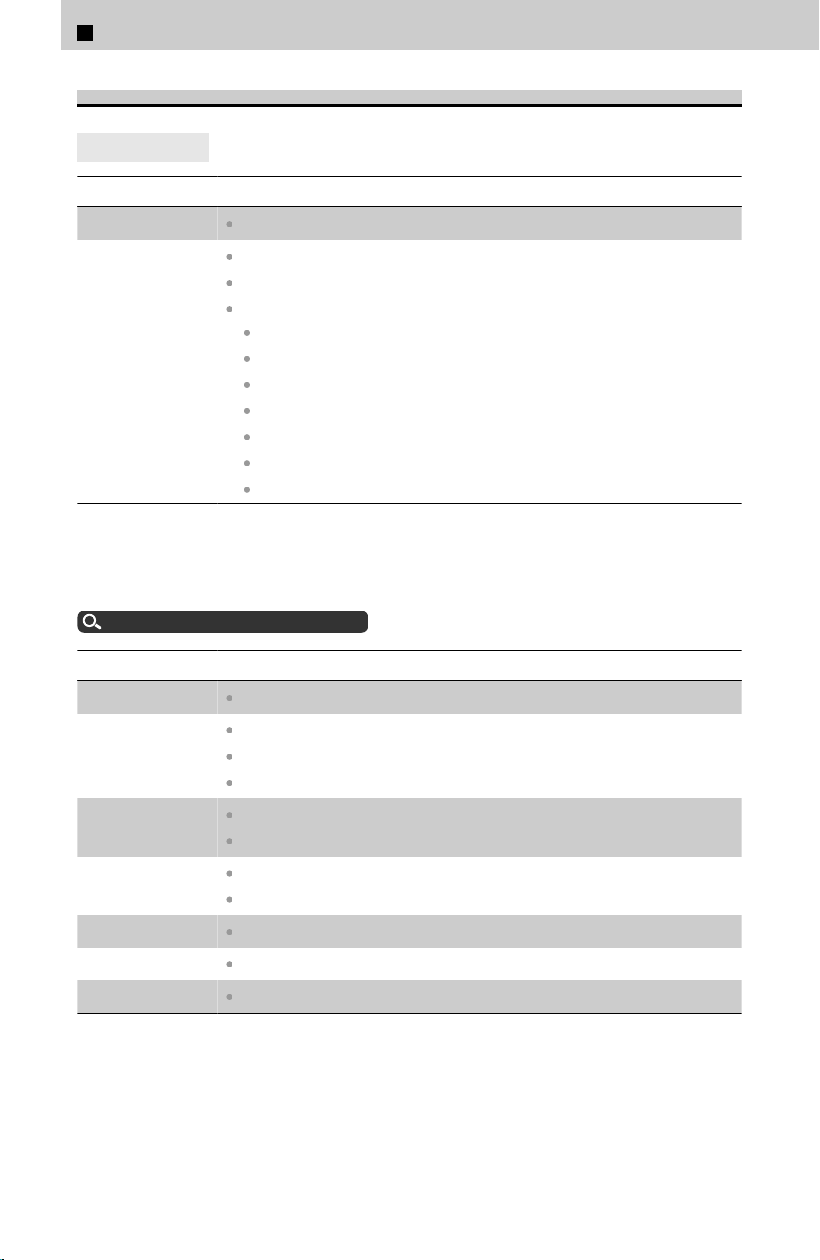
Maintenance Service Items
4
U.S. models
CODE Maintenance Main Items
A
Replace engine oil
*1
B
Replace engine oil
*1
and oil filter
Inspect front and rear brakes
Inspect these items:
Tie rod ends, steering gearbox, and boots
Suspension components
Driveshaft boots
Brake hoses and lines (including ABS/VSA
®
)
All fluid levels and condition of fluids
Exhaust system
#
Fuel lines and connections
#
*1: If a Maintenance Minder message does not appear more than 12 months after the display is
reset, change the engine oil every year.
#: See information on maintenance and emissions warranty.
About Warranty Coverages
u
P.424
CODE Maintenance Sub Items
1
Rotate tires
2
Replace air cleaner element
*2
Replace dust and pollen filter
*3
Inspect drive belt
3
Replace transmission fluid
Replace transfer fluid
4
Replace spark plugs
Replace timing belt and inspect water pump
*4
5
Replace engine coolant
6
Replace rear differential fluid
*5
7
Replace brake fluid
*6
*2: If you drive in dusty conditions, replace the air cleaner element every 15,000 miles (24,000
km).
*3: If you drive primarily in urban areas that have high concentrations of soot in the air from
industry and from diesel-powered vehicles, replace the dust and pollen filter every 15,000
miles (24,000 km).
*4: If you drive regularly in very high temperatures (over 110°F, 43°C), in very low temperatures
(under -20°F, -29°C), or towing a trailer, replace every 60,000 miles (100,000 km).
6
Maintenance > Maintenance Minder™
350
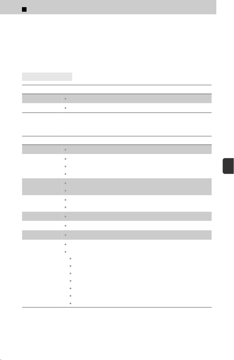
*5: Driving in mountainous areas at very low vehicle speeds or trailer towing results in higher
level of mechanical (Shear) stress to fluid. This requires differential fluid changes more
frequently than recommended by the Maintenance Minder. If you regularly drive your vehicle
under these conditions, have the differential fluid changed at 7,500 miles (12,000 km), then
every 15,000 miles (24,000 km).
*6: If a Maintenance Minder message does not appear more than 36 months after the display for
item 7 is reset, change the brake fluid every 3 years.
4
Canadian models
CODE Maintenance Main Items
A
Replace engine oil
*1
0
Replace engine oil
*1
and oil filter
*1: If a Maintenance Minder message does not appear more than 12 months after the display is
reset, change the engine oil every year.
CODE Maintenance Sub Items
1
Rotate tires
2
Replace air cleaner element
*2
Replace dust and pollen filter
*3
Inspect drive belt
3
Replace transmission fluid
Replace transfer fluid
4
Replace spark plugs
Replace timing belt and inspect water pump
*4
5
Replace engine coolant
6
Replace rear differential fluid
*5
7
Replace brake fluid
*6
9
Service front and rear brakes
Inspect these items:
Tie rod ends, steering gearbox, and boots
Suspension components
Driveshaft boots
Brake hoses and lines (including ABS/VSA
®
)
All fluid levels and condition of fluids
Exhaust system
#
Fuel lines and connections
#
*2: If you drive in dusty conditions, replace the air cleaner element every 24,000 km (15,000
miles).
6
Maintenance > Maintenance Minder™
351
6
Maintenance

*3: If you drive primarily in urban areas that have high concentrations of soot in the air from
industry and from diesel-powered vehicles, replace the dust and pollen filter every 24,000
km (15,000 miles).
*4: If you drive regularly in very high temperatures (over 43°C, 110°F), in very low temperatures
(under -29°C, -20°F), or towing a trailer, replace every 100,000 km (60,000 miles).
*5: Driving in mountainous areas at very low vehicle speeds or trailer towing results in higher
level of mechanical (Shear) stress to fluid. This requires differential fluid changes more
frequently than recommended by the Maintenance Minder. If you regularly drive your vehicle
under these conditions, have the differential fluid changed at 12,000 km (7,500 miles), then
every 24,000 km (15,000 miles).
*6: If a Maintenance Minder message does not appear more than 36 months after the display for
item 7 is reset, change the brake fluid every 3 years.
# : See information on maintenance and emissions warranty.
About Warranty Coverages
u
P.424
Resetting the Display
Reset the maintenance minder information display if you have performed the
maint
enance service.
[1] Set the power mode to ON.
[
2] Roll the right selector wheel until the Maintenance Minder screen is displayed.
[3] Press and hold the right selector wheel for about 10 seconds to enter the reset
mode.
[4] Roll the right selector wheel to select a maintenance item to reset, or to select
All due items (You can also select Cancel to end the process).
[5] Press the right selector wheel to reset the selected item.
[6] Repeat from step 3 for other items you wish to reset.
!
Failure to reset the Maintenance Minder™ display after a maintenance
ser
vice results in the system showing incorrect maintenance intervals,
which can lead to serious mechanical problems.
The dealer will reset the Maintenance Minder™ display after completing the required
maintenance service. If someone other than a dealer performs maintenance service,
reset the Maintenance Minder™ display yourself.
You can also reset the Maintenance Minder™ display using the audio/information
screen.
Customized Features
u
P.239
6
Maintenance > Maintenance Minder™
352
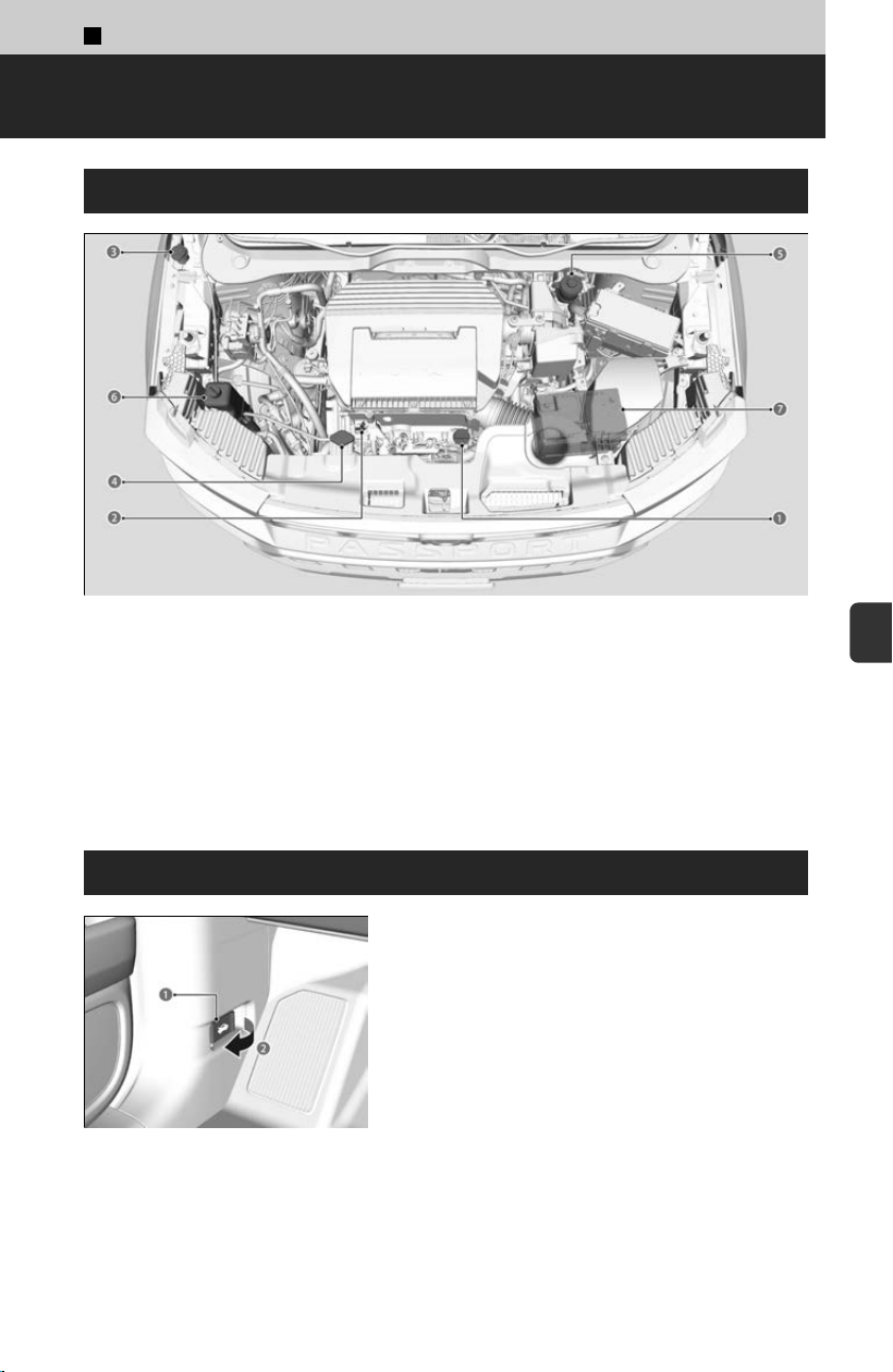
6
Maintenance >
Maintenance Under the Hood
Maintenance Items Under the Hood
a Engine Oil Fill Cap
b Engine Oil Dipstick (Orange)
c Washer Fluid
d Radiator Cap
e Brake Fluid (Black Cap)
f Engine Coolant Reserve Tank
g 12-Volt Battery
Opening the Hood
a Hood Release Handle
b Pull
[1] Pull the hood release handle under the
driv
er’s side lower corner of the dashboard.
≫
The hood will pop up slightly.
353
6
Maintenance
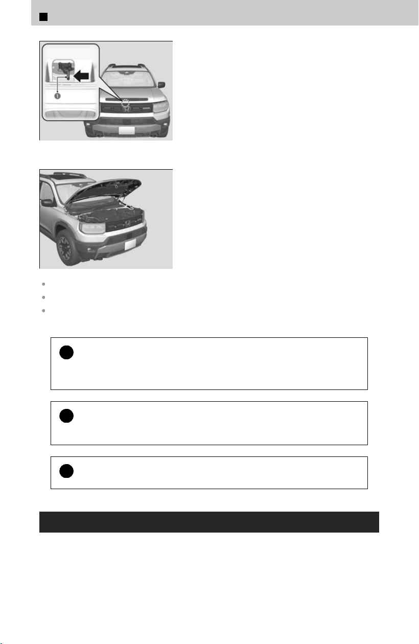
a Lever
[2] Push the hood latch lever (located under the
fr
ont edge of the hood to the center) to the
side and raise the hood. Once you have
raised the hood slightly, you can release the
lever.
[3] Lift the hood up most of the way.
≫
The hydraulic supports will lift it up the rest of
the way and hold it up.
Park the vehicle on a level surface, and set the parking brake.
When closing the hood, check that the hood is securely latched.
If the hood latch lever moves stiffly, or if you can open the hood without lifting the lever, the
latch mechanism should be cleaned and lubricated.
!
Do not open the hood when the wiper arms are raised.
The hood wil
l strike the wipers, resulting in possible damage to the hood and/or
the wipers.
!
Do not press the engine cover forcibly. This may damage the engine
c
over and component parts.
!
Do not open the hood while the Auto Idle Stop function is activated.
Recommended Engine Oil
Use a Genuine Honda Motor Oil or another commercial engine oil of suitable viscosity
f
or the ambient temperature as shown.
Oil is a major contributor to your engine’s performance and longevity. If you drive the
vehicle with insufficient or deteriorated oil, the engine may fail or be damaged.
6
Maintenance > Maintenance Under the Hood
354
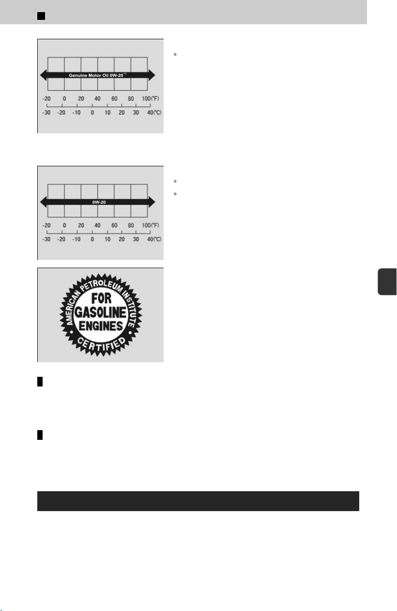
Genuine Engine Oil
Honda Genuine Motor Oil
*1: Formulated to improve fuel economy.
Commercial Engine Oil
API service SN or higher grade
API Certification Mark “Starburst”
The seal shown left indicates the oil is energy
conserving and that it meets the American
Petroleum Institute’s latest requirements.
Engine oil additives
Your vehicle does not require oil additives. In fact, they may adversely affect the
engine per
formance and durability.
Synthetic oil
You may also use synthetic motor oil if it is labeled with the API Cer
tification Seal
and is the specified viscosity grade.
Oil Check
We recommend that you check the engine oil level every time you refuel.
Park the vehicle on level ground.
Wait approximately three minutes after turning the engine off before you check the
oil
.
6
Maintenance > Maintenance Under the Hood
355
6
Maintenance
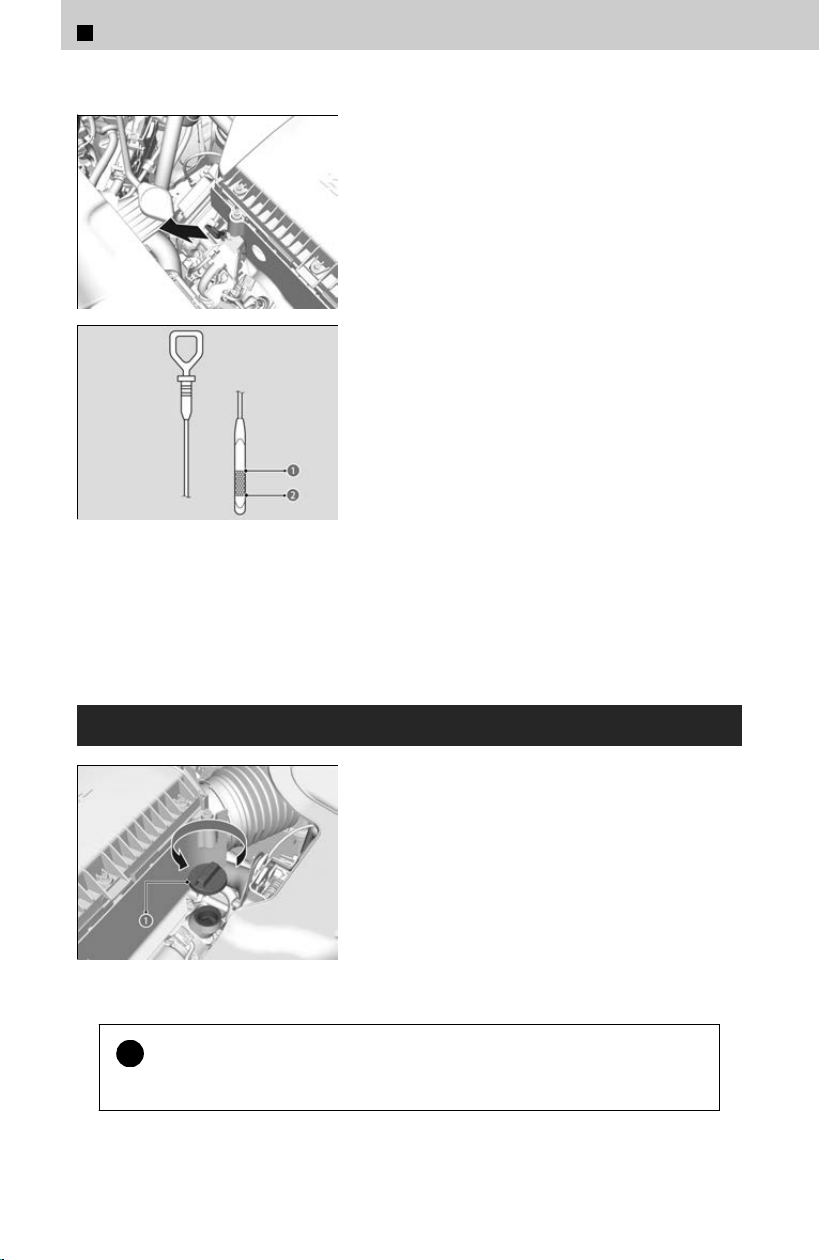
[1] Remove the dipstick (orange).
[2] Wipe the dipstick with a clean cloth or paper
towel.
[3] Insert the dipstick back all the way into its
hole.
a Upper Mark
b Lower Mark
[4] Remove the dipstick again, and check the
le
vel. It should be between the upper and
lower marks. Add oil if necessary.
If the oil level is near or below the lower mark, slowly add oil, being careful not to
o
verfill.
Adding Engine Oil
a Engine Oil Fill Cap
[1] Unscrew and remove the engine oil fil
l cap.
[2] Add oil slowly.
[3] Reinstall the engine oil fill cap, and tighten it
securely.
[4] Wait for three minutes and recheck the
engine oil dipstick.
!
Do not fil
l the engine oil above the upper mark. Overfilling the engine
oil may result in leaks and engine damage.
6
Maintenance > Maintenance Under the Hood
356
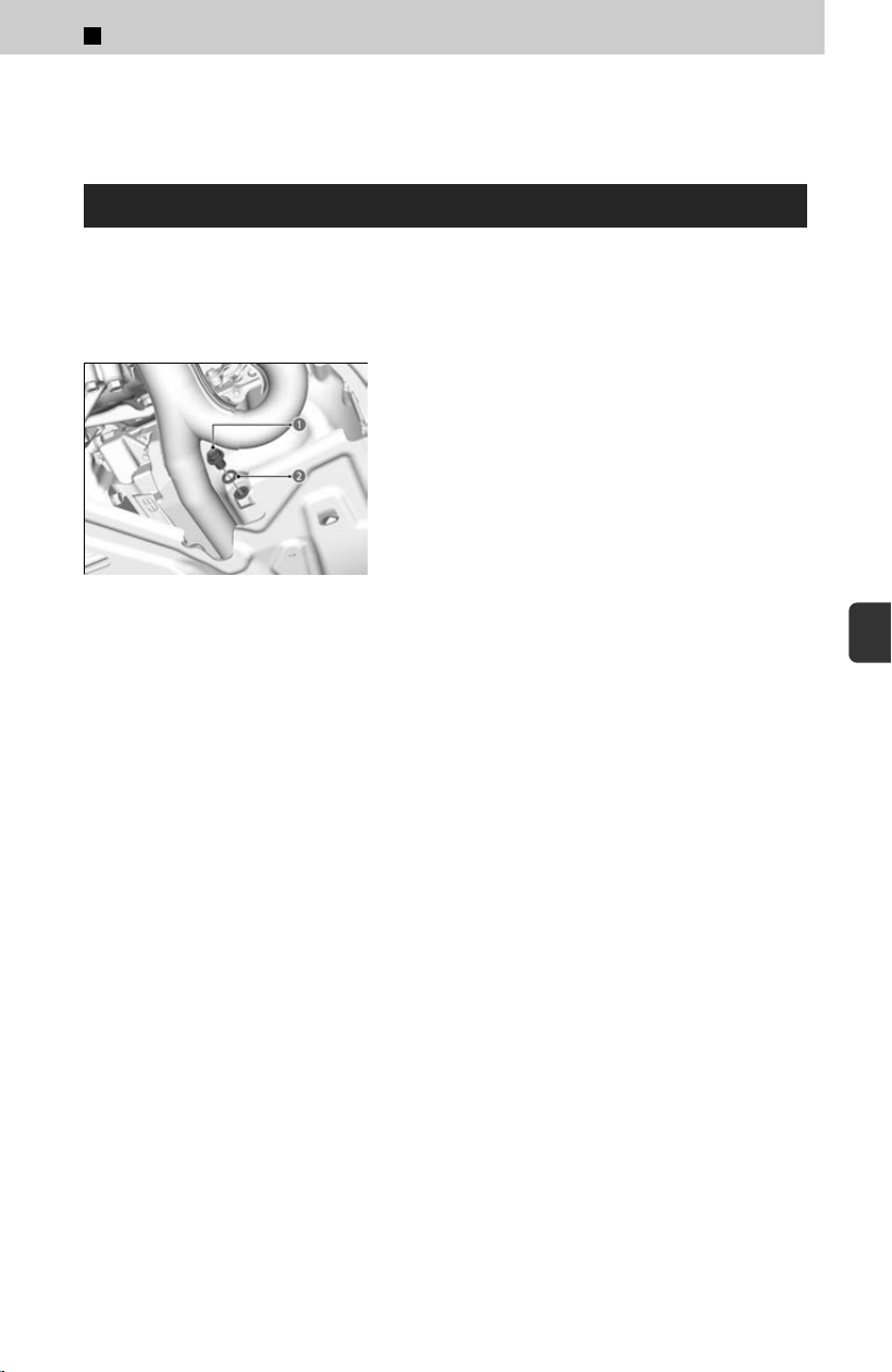
If any oil spills, wipe it away immediately. Spilled oil may damage the engine
compartment components.
Changing the Engine Oil and Oil Filter
You must change the engine oil and oil fil
ter regularly in order to maintain the engine’s
lubrication. The engine may be damaged if they are not changed regularly.
Change the oil and filter in accordance with the maintenance message on the driver
information interface.
a Drain Bolt
b Washer
[1] Run the engine until it reaches normal
oper
ating temperature, and then turn the
engine off.
[2] Open the hood and remove the engine oil fill
cap.
[3] Remove the drain bolt and washer from the
bottom of the engine, and drain the oil into a
suitable container.
6
Maintenance > Maintenance Under the Hood
357
6
Maintenance
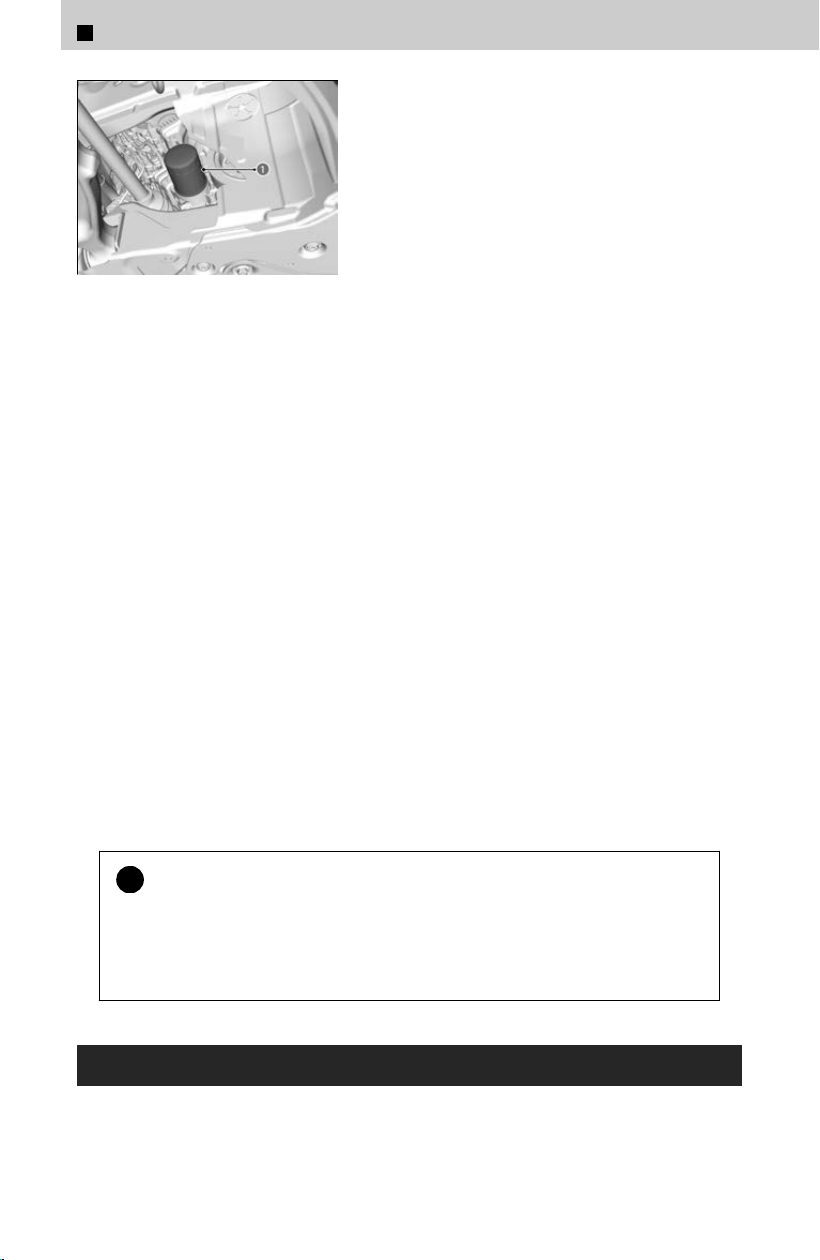
a Oil Filter
[4] Remove the oil fil
ter and dispose of the
remaining oil.
[5] Check that the filter gasket is not stuck to
the engine contact surface.
≫
If it is stuck, you must detach it.
[6] Wipe away dirt and dust adhering to the
c
ontact surface of the engine block, and
install a new oil filter.
≫
Apply a light coat of new engine oil to the filter
gasket.
[7] Put a new washer on the drain bolt, then
r
einstall the drain bolt.
≫
Tightening torque: 30 lbf∙ft (40 N∙m, 4.0 kgf∙m)
[8] Pour the recommended engine oil into the
engine
.
≫
Engine oil change capacity (including filter): 5.8
US qt (5.5 L)
[9] Reinstall the engine oil fil
l cap securely and
start the engine.
[
10
] Run the engine for a few minutes, and then
check that there is no leak from the drain
bolt or oil filter.
[
11
] Stop the engine, wait for three minutes, and
then check the oil level on the dipstick.
≫
If necessary, add more engine oil.
You will need a special wrench to replace the oil fil
ter. You can buy this wrench from a
dealer.
When installing the new oil filter, follow the instructions supplied with the oil filter.
Reinstall the engine oil fill cap. Start the engine. If the Engine oil pressure low
warning appears, turn off the engine, and check your work.
!
You may damage the environment if you do not dispose of the oil in a
suitable w
ay. If you are changing the oil by yourself, appropriately
dispose of the used oil. Put the oil in a sealed container and take it to a
recycling center. Do not throw the oil away into a garbage can or onto
the ground.
Engine Coolant
Specified c
oolant: Honda Long Life Antifreeze/Coolant Type 2
This coolant is premixed with 50% antifreeze and 50% water. Do not add any straight
antifreeze or water.
6
Maintenance > Maintenance Under the Hood
358
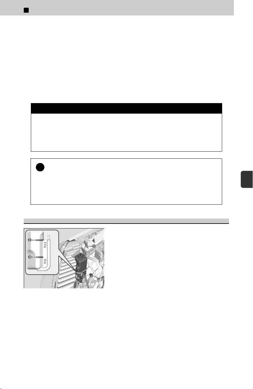
We recommend you check the engine coolant level every time you refuel. Check the
reserve tank first. If it is completely empty, also check the coolant level in the radiator.
Add the engine coolant accordingly.
If Honda antifreeze/coolant is not available, you may use another major brand of non-
silicate coolant as a temporary replacement. Check that it is a high quality coolant
recommended for aluminum engines. Continued use of any non-Honda coolant can
result in corrosion, causing the cooling system to malfunction or fail. Have the cooling
system flushed and refilled with Honda antifreeze/coolant as soon as possible.
Do not add rust inhibitors or other additives to your vehicle’s cooling system. They
may not be compatible with the coolant or with the engine components.
3 WARNING
Removing the radiator cap while the engine is hot can cause hot coolant to
spr
ay out, seriously scalding you.
Always let the engine and radiator cool down before removing the radiator
cap.
!
Genuine Honda engine coolant is a 50/50 mixture of antifreeze and
w
ater that can withstand freezing at temperatures as low as about
-31°F (-35°C). If your vehicle is consistently subjected to
temperatures below this, the concentration of antifreeze in the coolant
should be increased. Consult a dealer for details.
Reserve Tank
a Reserve Tank
b MAX
c MIN
[1] Mak
e sure the engine and radiator are
cool.
[2] Check the amount of coolant in the reserve
tank.
≫
If the coolant level is below the MIN mark, add
the specified coolant until it reaches the MAX
mark.
[3] Inspect the cooling system for leaks.
6
Maintenance > Maintenance Under the Hood
359
6
Maintenance
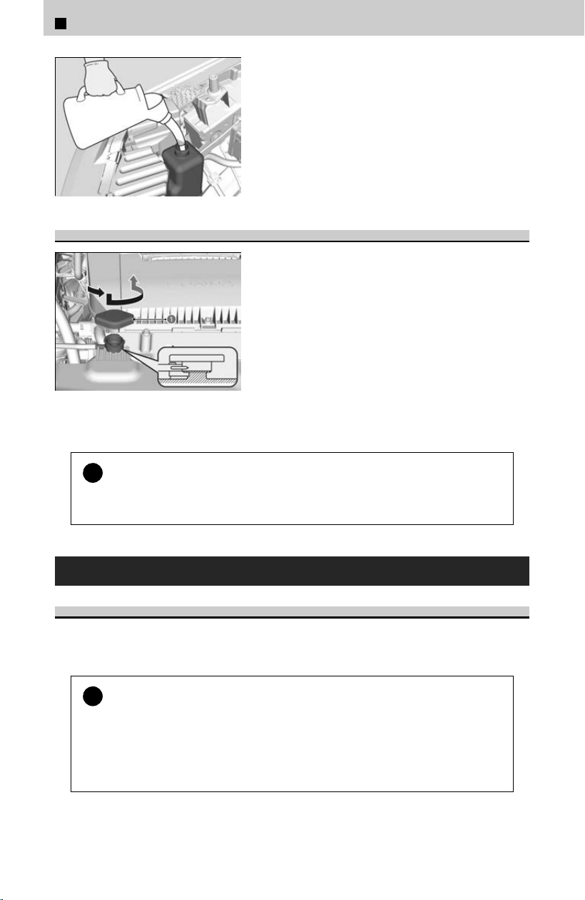
Radiator
a Radiator Cap
[1] Mak
e sure the engine and radiator are
cool.
[2] Turn the radiator cap 1/8th turn
counterclockwise and relieve any pressure in
the cooling system.
[3] Push down and turn the radiator cap
counterclockwise to remove it.
[4] The coolant level should be up to the base of
the filler neck. Add coolant if it is low.
[5] Put the radiator cap back on, and tighten it
fully.
!
Pour the fluid slowly and carefully so you do not spill any.
Clean up an
y spills immediately; they can damage components in the engine
compartment.
Transmission Fluid
Automatic Transmission Fluid
Specified fluid: Honda A
TF-type 2.0
Have a dealer check the fluid level and replace if necessary.
!
Do not mix Honda ATF-type 2.0 with other transmission fluids.
Using a tr
ansmission fluid other than Honda ATF-type 2.0 may adversely affect
the operation and durability of your vehicle’s transmission, and damage the
transmission.
Any damage caused by using a transmission fluid that is not equivalent to
Honda ATF-type 2.0 is not covered by Honda’s new vehicle limited warranty.
6
Maintenance > Maintenance Under the Hood
360
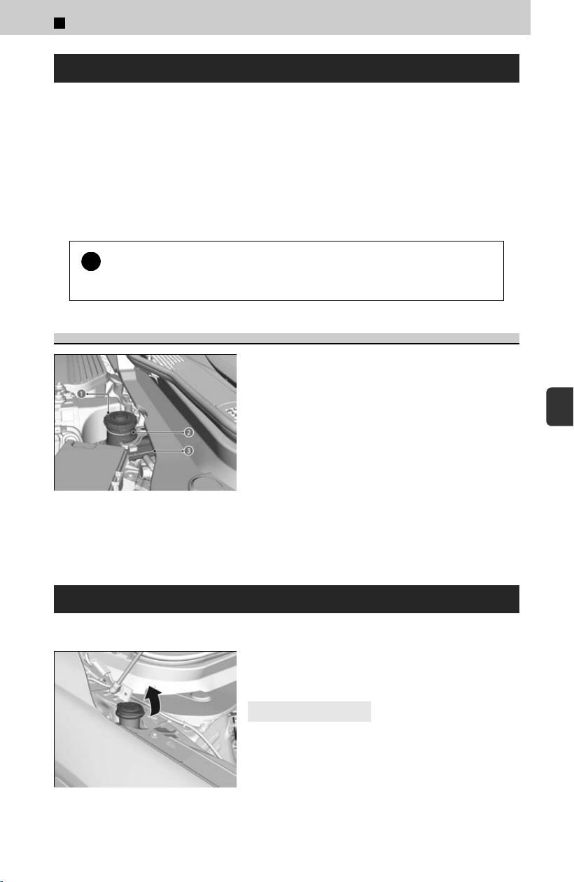
Brake Fluid
Specified fluid: Honda Heavy Dut
y Brake Fluid DOT 3
If the specified brake fluid is not available, you should use only DOT 3 or DOT 4 fluid
from a sealed container as a temporary replacement.
Using any non-Honda brake fluid can cause corrosion and decrease the longevity of
the system. Have the brake system flushed and refilled with Honda Heavy Duty Brake
Fluid DOT 3 as soon as possible.
If the brake fluid level is at or below the MIN mark, have a dealer inspect the vehicle
for leaks or worn brake pads as soon as possible.
!
Brake fluid marked DOT 5 is not compatible with your vehicle's braking
s
ystem and can cause extensive damage.
Checking the Brake Fluid
a Brake Reservoir
b MAX
c MIN
The fluid level should be between the MIN and
MA
X marks on the side of the reserve tank.
Refilling Window Washer Fluid
Open the cap and check the amount of window washer fluid.
If the level is low, add washer fluid.
4
Canadian models
If the washer fluid is low, a message appears on
the driv
er information interface.
Pour the washer fluid carefully. Do not overflow the reservoir.
6
Maintenance > Maintenance Under the Hood
361
6
Maintenance

!
Do not use engine antifreeze or a vinegar/water solution in the
windshield w
asher reservoir.
Antifreeze can damage your vehicle’s paint. A vinegar/water solution can
damage the windshield washer pump.
Use only commercially available windshield washer fluid.
Avoid prolonged use of hard water to prevent lime scale buildup.
6
Maintenance > Maintenance Under the Hood
362
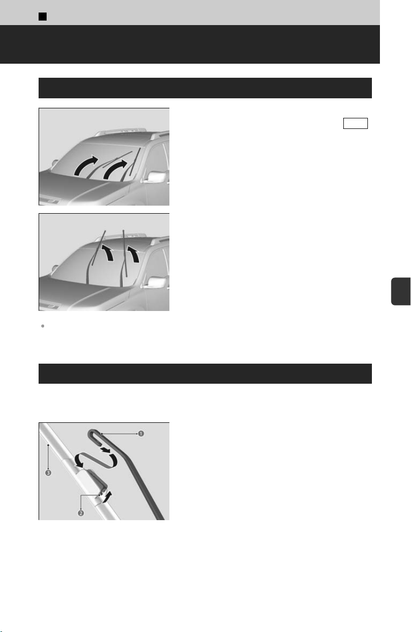
6
Maintenance >
Checking and Maintaining Wiper Blades
Lifting the Front Wiper Arms
[1] Set the power mode to VEHICLE OFF.
[2] While holding the wiper switch in the MIST
position, set the power mode to ON, then to
VEHICLE OFF.
≫
Both wiper arms are set to the maintenance
position as shown in the image.
[3] Lift both wiper arms.
When lifting the wiper arms, always follow the instructions to move them into the
maintenance position. The wiper arms may be damaged if they are moved manually.
Changing the Front Wiper Blade Rubber
If the wiper blade rubber has deteriorated, it will leave streaks and become noisy, and
the har
d surfaces of the blade may scratch the window glass.
a Wiper Arm
b Tab
c Holder
[1] Lift both wiper arms.
[
2] Press up on and hold the tab, then slide the
holder off the wiper arm.
363
6
Maintenance
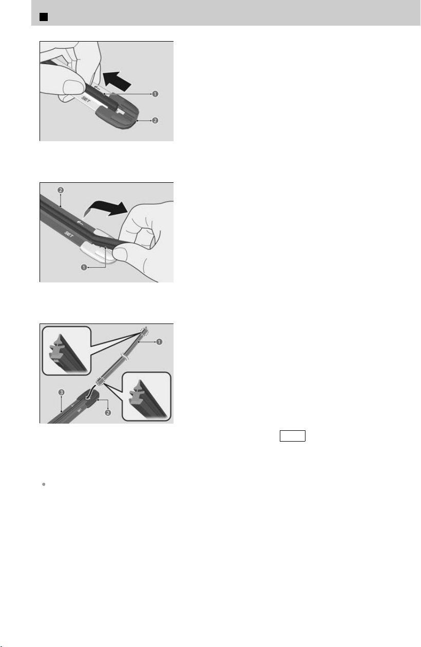
a Wiper Blade
b End cap at the bottom
[3] Pull the end of the wiper blade in the
dir
ection of the arrow in the image until it is
out of the holder’s end cap.
a Wiper Blade
b Holder
[4] Pull the wiper blade in the opposite direction
t
o slide it out of the holder.
a Wiper Blade
b Cap
c Holder
[5] Insert the flat side of the new wiper blade
ont
o the bottom part of the holder. Insert the
blade all the way.
[6] Install the end of the wiper blade into the
cap.
[7] Slide the holder onto the wiper arm until it
locks.
[8] Lower both wiper arms.
[9] Set the power mode to ON and hold the
wiper switch in the MIST position until both
wiper arms return to the standard position.
Avoid dropping the wiper arm onto the windshield, as it may damage the wiper arm and/or the
windshield.
6
Maintenance > Checking and Maintaining Wiper Blades
364
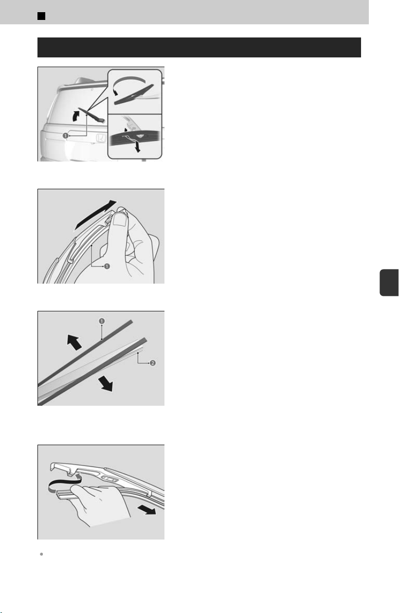
Changing the Rear Wiper Blade Rubber
a Wiper Arm
[1] Raise the wiper arm off.
[
2] Pivot the bottom end of the wiper blade up
until it comes off from the wiper arm.
a Wiper Blade
[3] Slide the wiper blade out from the end with
the indent
.
a Retainer
b Rubber
[4] Remove the retainers from wiper blade and
mount t
o a new rubber blade.
[5] Slide the new wiper blade onto the holder.
≫
Make sure it is engaged correctly, then install
the wiper blade assembly onto the wiper arm.
Avoid dropping the wiper arm, as it may damage the rear window.
6
Maintenance > Checking and Maintaining Wiper Blades
365
6
Maintenance

Do not try to forcefully lift up the wiper arm.
The wiper arm may be damaged if it is lifted too high.
6
Maintenance > Checking and Maintaining Wiper Blades
366

6
Maintenance >
Checking and Maintaining Tires
Checking Tires
Have a dealer check the tires if you feel a consistent vibration while driving. New tires
and an
y that have been removed and reinstalled should be properly balanced.
Measure the air pressure when tires are cold. This means the vehicle has been parked for at
least three hours, or driven less than 1 mile (1.6 km). If necessary, add or release air until the
specified pressure is reached.
If checked when hot, tire pressure can be as much as 4–6 psi (30–40 kPa, 0.3–0.4 kgf/cm
2
)
higher than if checked when cold.
3 WARNING
Using tires that are excessively worn or improperly inflated can cause a
cr
ash in which you can be seriously hurt or killed.
Follow all instructions in this owner’s manual regarding tire inflation and
maintenance.
Tire Requirements for Safe Driving
To safely operate your vehicle, your tires must be of the proper type and size, in good
c
ondition with adequate tread, and properly inflated.
Tires are the correct size and type.
The ground beneath the tires is in good condition.
The tire pressure is correct.
The tires do not have any wear, scratches, cracks, or foreign objects.
Inflation guidelines
Properly inflated tires provide the best combination of handling, tread life, and
c
omfort. Refer to the driver’s doorjamb label or specifications page for the specified
pressure.
Underinflated tires wear unevenly, adversely affect handling and fuel economy, and
ar
e more likely to fail from overheating.
Overinflated tires make your vehicle ride harshly, are more prone to road hazards,
and wear unevenly.
Every day before you drive, look at each of the tires. If one looks lower than the
others, check the pressure with a tire gauge.
At least once a month or before long trips, use a gauge to measure the pressure in
all tires, including the spare. Even tires in good condition can lose 1-2 psi (10-20
kPa, 0.1-0.2 kgf/cm
2
) per month.
367
6
Maintenance
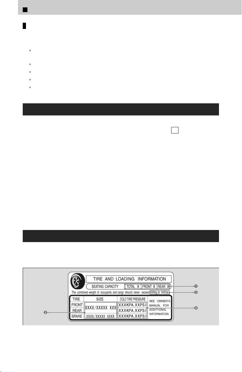
Inspection guidelines
Every time you check inflation, also examine the tires and valve stems.
Look for:
Bumps or bulges on the side or in the tread. Replace the tire if you find any cuts, splits, or
cracks in the side of the tire. Replace it if you see fabric or cord.
Remove any foreign objects and inspect for air leaks.
Uneven tread wear. Have a dealer check the wheel alignment.
Excessive tread wear.
Cracks or other damage around valve stem.
Tire Fill Assist
TPMS with Tire Fill Assist provides visual and audible assistance during tire pressure
adjus
tment. With the power mode in ON and the transmission in P , while you adjust
tire pressure up or down, the system alerts you as follows:
Below recommended pressure: The beeper sounds and exterior lights flash once
every five seconds.
At recommended pressure: The beeper sounds and exterior lights flash rapidly for
three seconds with five-second intervals. Stop filling the tire.
Above recommended pressure: The beeper sounds and lights flash twice every two
seconds.
When a certain amount of time has passed since the power mode is set to ON, Tire
Fill Assist will be canceled until you set the power mode to OFF.
You cannot use Tire Fill Assist if the engine was started by the remote engine start, or
if there is a malfunction in the system. If Tire Fill Assist does not work, use a tire
pressure gauge.
Tire and Loading Information Label
The label attached to the driver’s doorjamb provides necessary tire and loading
inf
ormation.
Label Example
The tire and loading information label attached to the driver’s doorjamb contains:
6
Maintenance > Checking and Maintaining Tires
368
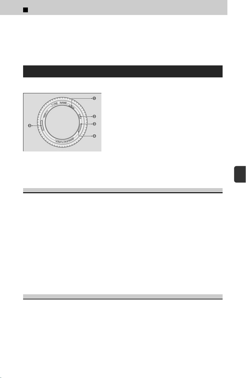
a The number of people your vehicle can carry.
b The total weight your vehicle can carry. Do not exceed this weight.
c The original tire sizes for front, rear, and spare.
d The proper cold tire pressure for front, rear, and spare.
Tire Labeling
Example
a Tire Size
b Tire Identification Number (TIN)
c Maximum Tire Load
d Maximum Tire Pressure
e Tire Size
The tires that came on your vehicle have a number of markings. Those you should be
aw
are of are described as shown.
Tire Sizes
Whenever tires are replaced, they should be replaced with tires of the same size.
Following is an example of tire size with an explanation of what each component
means
.
P235/60 R18 102T
P: Vehicle type (P indicates passenger vehicle).
235: Tire width in millimeters.
60: Aspect ratio (the tire’s section height as a percentage of its width).
R: Tire construction code (R indicates radial).
18: Rim diameter in inches.
102: Load index (a numerical code associated with the maximum load the tire can
carry).
T: Speed symbol (an alphabetical code indicating the maximum speed rating).
Tire Identification Number (TIN)
The tire identification number (
TIN) is a group of numbers and letters that look like
the examples in the side column. TIN is located on the sidewall of the tire.
There are two different formats that TIN may be listed in.
Format A
DOT B97R FW6X 2209
6
Maintenance > Checking and Maintaining Tires
369
6
Maintenance

DOT: This indicates that the tire meets all requirements of the U.S. Department of
Transportation.
B97R: Manufacturer’s identification mark.
FW6X: Tire type code.
2209: Date of manufacture (22: Week, 09: Year).
Format B
DOT 1A3 OFBEKP 1522
DOT: This indicates that the tire meets all requirements of the U.S. Department of
Transportation.
1A3: PLANT CODE
OFBEKP: MANUFACTURE CODE
1522: DATE CODE (15: Week, 22: Year)
Glossary of Tire Terminology
Cold Tire Pressure– The tir
e air pressure when the vehicle has been parked for at
least three hours or driven less than 1 mile (1.6 km).
Load Rating– Means the maximum load that a tire is rated to carry for a given
inflation pressure.
Maximum Inflation Pressure– The maximum tire air pressure that the tire can hold.
Maximum Load Rating– Means the load rating for a tire at the maximum permissible
inflation pressure for that tire.
Recommended Inflation Pressure– The cold tire inflation pressure recommended
by the manufacturer.
Treadwear Indicators (TWI)– Means the projections within the principal grooves
designed to give a visual indication of the degrees of wear of the tread.
DOT Tire Quality Grading (U.S. Vehicles)
The tires on your vehicle meet all U.S. Federal Safety
R
equirements. All tires are also graded for treadwear, traction,
and temperature performance according to Department of
Transportation (DOT) standards. The following explains these
gradings.
Uniform Tire Quality Grading
Quality grades can be found where applicable on the tire
side
wall between tread shoulder and maximum section width.
For example:
Treadwear 200
6
Maintenance > Checking and Maintaining Tires
370

Traction AA
Temperature A
All passenger car tires must conform to Federal Safety
Requirements in addition to these grades.
Treadwear
The treadwear grade is a comparative rating based on the wear
r
ate of the tire when tested under controlled conditions on a
specified government test course. For example, a tire graded
150 would wear one and one-half (1 1/2) times as well on the
government course as a tire graded 100. The relative
performance of tires depends upon the actual conditions of
their use, however, and may depart significantly from the norm
due to variations in driving habits, service practices and
differences in road characteristics and climate.
Traction
The traction grades, from highest to lowest, are AA, A, B, and C.
Those gr
ades represent the tire’s ability to stop on wet
pavement as measured under controlled conditions on specified
government test surfaces of asphalt and concrete. A tire marked
C may have poor traction performance.
Warning: The traction grade assigned to this tire is based on
s
traight-ahead braking traction tests, and does not include
acceleration, cornering, hydroplaning, or peak traction
characteristics.
6
Maintenance > Checking and Maintaining Tires
371
6
Maintenance
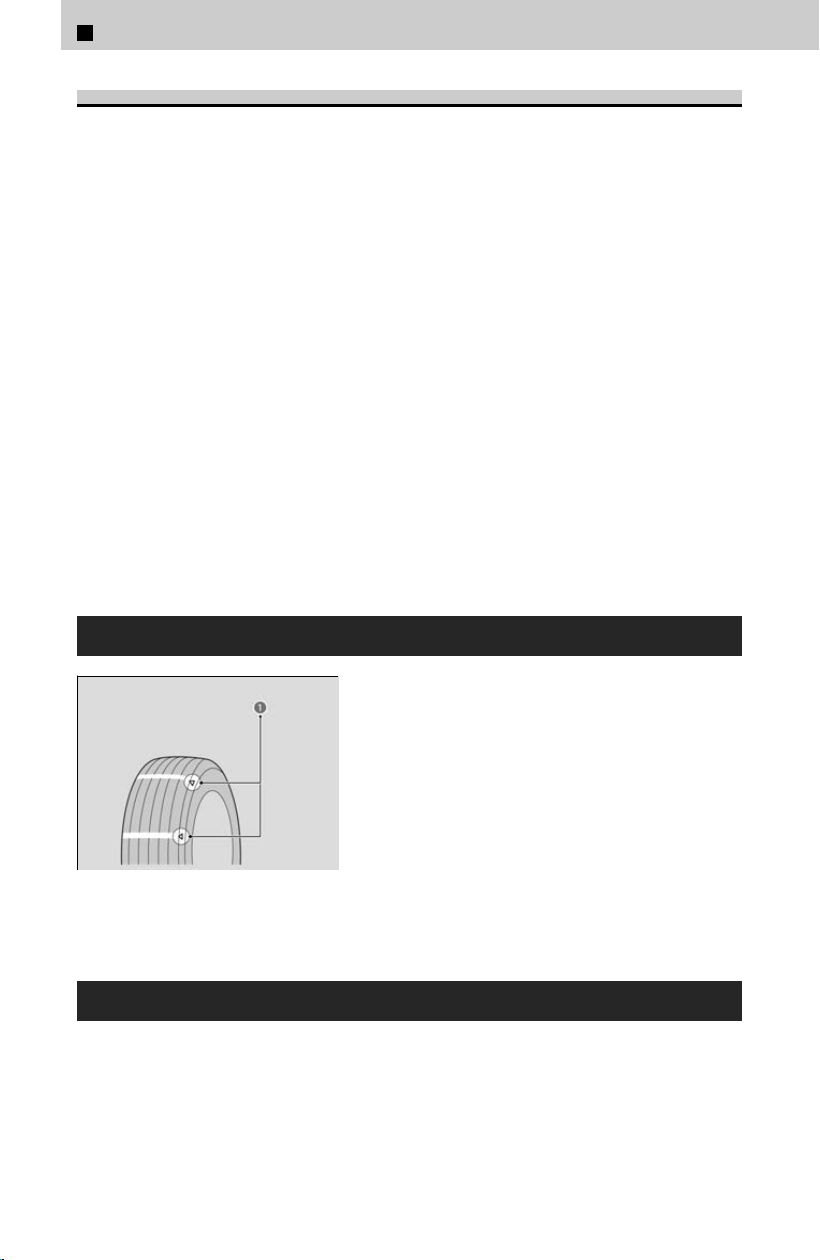
Temperature
The temperature grades are A (the highest), B, and C,
r
epresenting the tire’s resistance to the generation of heat and
its ability to dissipate heat when tested under controlled
conditions on a specified indoor laboratory test wheel.
Sustained high temperature can cause the material of the tire to
degenerate and reduce tire life, and excessive temperature can
lead to sudden tire failure. The grade C corresponds to a level of
performance which all passenger car tires must meet under the
Federal Motor Vehicle Safety Standard No. 109. Grades B and A
represent higher levels of performance on the laboratory test
wheel than the minimum required by law.
Warning: The temperature grade for this tire is established for a
tir
e that is properly inflated and not overloaded. Excessive
speed, underinflation, or excessive loading, either separately or
in combination, can cause heat buildup and possible tire failure.
Wear Indicators
a Example of a Wear Indicator
mark
The groove where the wear indicator is located is
about 1/16 inch (about 1.6 mm) shal
lower than
elsewhere on the tire. If the tread has worn so
that the indicator is exposed, replace the tire.
Worn out tires have poor traction on wet roads.
Tire Service Life
The life of your tires is dependent on many factors, including driving habits, road
c
onditions, vehicle loading, inflation pressure, maintenance history, speed, and
environmental conditions (even when the tires are not in use).
6
Maintenance > Checking and Maintaining Tires
372

In addition to regular inspections and inflation pressure maintenance, it is
recommended that you have annual inspections performed once the tires reach five
years old. All tires, including the spare, should be removed from service after 10 years
from the date of manufacture, regardless of their condition or state of wear.
Tire and Wheel Replacement
Replace your tires with radials of the same size, load range, speed rating, and
maximum c
old tire pressure rating (as shown on the tire’s sidewall). Using tires of a
different size or construction can cause certain vehicle systems such as the ABS and
Vehicle Stability Assist™(VSA
®
) system to work incorrectly.
It is best to replace all four tires at the same time. If that isn’t possible, replace the
fr
ont or rear tires in pairs.
Whenever you have a tire replaced or reset, make sure that the rubber valve stem is
replaced and that the TPMS sensor is transferred from the old valve stem to the new
one.
If you replace a wheel, make sure that the wheel’s specifications match those of the
original wheels.
3 WARNING
Installing improper tires on your vehicle can affect handling and stability.
This can cause a cr
ash in which you can be seriously hurt or killed.
Always use the size and type of tires recommended in this owner’s manual.
Winter Tires
If driving on snowy or frozen roads, mount all season marked M+S tir
es, or snow tires;
reduce speed; and maintain sufficient distance between vehicles when driving.
Be particularly careful when operating the steering wheel or brakes to prevent
skidding.
Use snow tires, or all season tires when necessary or according to the law.
When mounting, refer to the following points.
If your vehicle is equipped with summer tires, be aware that these tires are not
designed for winter driving conditions. For more information, contact a dealer.
For winter tires
For winter tires:
Select the size and load ranges that are the same as the original tires.
Mount the tires to all four wheels.
6
Maintenance > Checking and Maintaining Tires
373
6
Maintenance
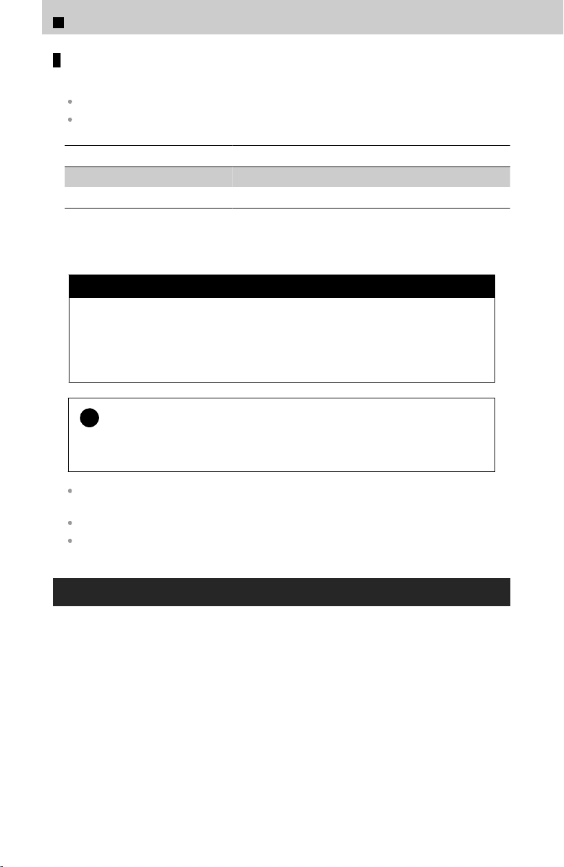
For tire chains
For tire chains:
Install them on the front tires only.
Because your vehicle has limited tire clearance, we strongly recommend using the chains
listed below:
Original Tire Size Chain Type
265/60R18 Peerless Auto-Trac 0232605
275/60R18 Not Available
When tire chains are mounted, follow the chain manufacturer’s instructions
regarding vehicle operational limits.
3 WARNING
Using the wrong chains, or not properly installing chains, can damage the
br
ake lines and cause a crash in which you can be seriously injured or killed.
Follow all instructions in this owner’s manual regarding the selection and
use of tire chains.
!
Traction devices that are the wrong size or improperly installed can
damag
e your vehicle’s brake lines, suspension, body, and wheels. Stop
driving if they are hitting any part of the vehicle.
Follow the chain manufacturer’s instruction when installing. Mount them as tightly as you
can.
Check that the chains do not touch the brake lines or suspension.
Drive slowly.
Tire Rotation
Rotating tires according to the maintenance messages on the driver information
int
erface helps to distribute wear more evenly and increase tire life.
6
Maintenance > Checking and Maintaining Tires
374
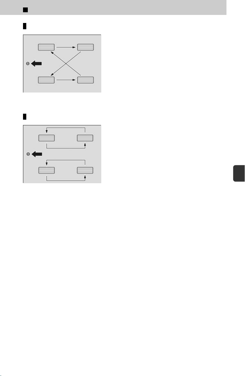
Tires without rotation marks
a Front
Tires with rotation marks
a Front
Wheel nut torque for the tires that come standard-equipped with your vehicle is as
f
ollows.
Wheel nut torque:
94 lbf・ft (127 N・m, 13 kgf・m)
6
Maintenance > Checking and Maintaining Tires
375
6
Maintenance

6
Maintenance >
12-Volt Battery
Maintaining 12-Volt Battery
After re-connecting the 12-volt battery: if various
indicators come on and the message on the left is
displayed on the driver information interface, with
the engine running, turn the steering wheel to the
left until it stops then to the right until it stops,
then drive a short distance at more than 12 mph
(20 km/h). If the indicator does not go off, have
your vehicle checked by a dealer.
When you find c
orrosion, clean the 12-volt battery terminals by applying a baking
powder and water solution.
Clean the terminals with a damp towel. Cloth/towel dry the 12-volt battery. Coat the
terminals with grease to help prevent future corrosion.
When replacing the 12-volt battery, the replacement must be of the same
specifications.
Consult a dealer for more information.
3 WARNING
The 12-volt battery gives off explosive hydrogen gas during normal
oper
ation.
A spark or flame can cause the 12-volt battery to explode with enough
force to kill or seriously hurt you.
When conducting any 12-volt battery maintenance, wear protective
clothing and a face shield, or have a skilled technician do it.
WARNING: Battery post, terminals, and related accessories
contain lead and lead compounds.
Wash your hands after handling.
The 12-volt battery installed in this vehicle is specifical
ly designed for a model with
Auto Idle Stop or System Updates. Using a 12-volt battery other than this specified
type may shorten the battery life, and prevent Auto Idle Stop or System Updates from
activating. If you need to replace the battery, make sure to select the specified type
and size. Ask a dealer for more details.
376

Checking the 12-Volt Battery
Check the 12-volt battery terminals for corrosion monthly.
If your vehicle’s 12-volt battery is disconnected or goes dead:
The audio system is disabled.
The clock resets.
4
Canadian models
The immobilizer system needs to be reset.
Immobilizer System
u
P.48
Charging the AGM Battery
AGM labeled batteries like those installed in your vehicle require a compatible
char
ger to be properly charged. Damage to the battery can result if the battery is
charged improperly or with the wrong equipment. For more information on how to
charge your vehicle’s AGM battery, consult a dealer.
If the battery cable is removed while a system update is being performed, the
electrical system can be permanently damaged. Only remove the battery cable when
a system update is not being performed.
6
Maintenance > 12-Volt Battery
377
6
Maintenance
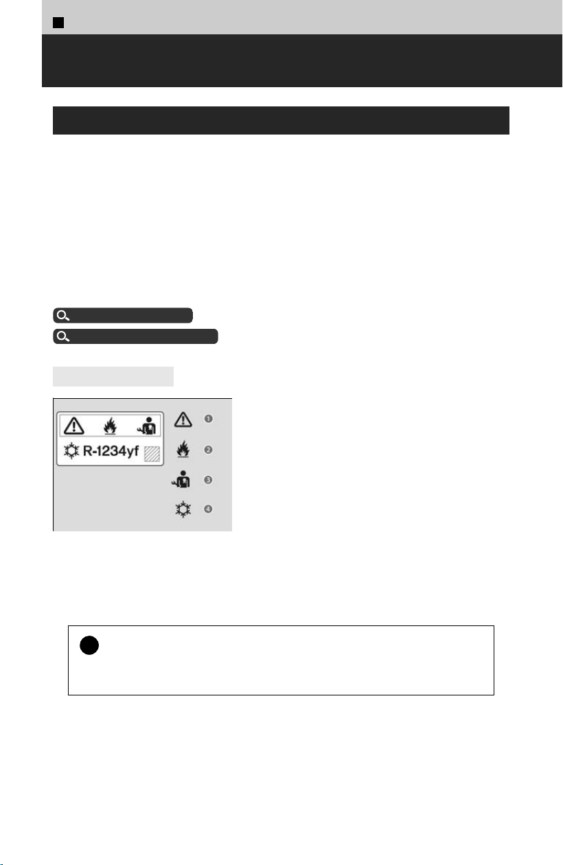
6
Maintenance >
Climate Control System Maintenance
Air Conditioning
To ensure proper and safe operation, the Society of Automotive Engineers (SAE
J2845) r
ecommends that the refrigerant system only be serviced by trained and
certified technicians.
Never repair or replace the air conditioning evaporator (cooling coil) with one
removed from a used or salvaged vehicle.
New replacement mobile air conditioning evaporators must be certified (and labeled)
as meeting SAE Standard J2842.
Refrigerant in your vehicle’s air conditioning system is flammable and can be ignited
during servicing if proper procedures are not followed.
The air conditioner label is found under the hood:
Label Locations
u
P.46
About Specification
u
P.416
4
Canadian models
a Caution
b Flammable R
efrigerant
c Requires Registered Technician to Service
d Air Conditioning System
!
Vented refrigerant is harmful to the environment.
T
o avoid refrigerant from venting, never replace the evaporator with one
removed from a used or salvaged vehicle.
The climate control system is equipped with a dust and pollen filter that collects
pollen, dust, and other debris in the air. The Maintenance Minder™ messages will let
you know when to replace the filter.
We recommend that you replace the dust and pollen filter sooner when using your
vehicle in areas with high concentrations of dust.
378
6
Maintenance >
Cleaning
Interior Care
Use a damp cloth with a mixture of mild detergent and warm water to remove dirt.
Use a clean cloth to remove detergent residue.
!
Do not spill liquids inside the vehicle.
Electrical de
vices and systems may malfunction if liquids are splashed on
them.
!
Do not use silicone-based sprays on electrical devices such as audio
de
vices and switches.
Doing so may cause the items to malfunction or cause a fire inside the vehicle.
If a silicone-based spray is inadvertently used on electrical devices, consult a
dealer.
!
Depending on their composition, chemicals and liquid aromatics may
cause disc
oloration, wrinkles, and cracking to resin-based parts and
textiles.
Do not use alkali solvents or organic solvents such as benzene or gasoline.
!
After using chemicals, make sure to gently wipe them away using a dry
cloth.
Do not plac
e used cloths on top of resin-based parts or textiles for long periods
of time without washing.
Cleaning Seat Belts
Use a soft brush with a mixture of mild soap and warm water to clean the seat
bel
ts. Let the belts air dry. Wipe the loops of the seat belt anchors using a clean
cloth.
Cleaning the Window
Wipe using a glass cleaner.
379
6
Maintenance
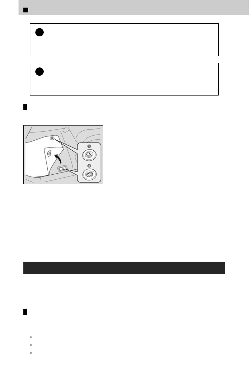
!
Wires are mounted to the inside of the rear window. Wipe along the
same dir
ection as the wires with a soft cloth so as not to damage
them.
!
Be careful not to spill fluids, such as water or glass cleaner, on or
ar
ound the cover of the electrical components around the rearview
mirror.
Floor Mats
Example
a Unlock
b Lock
The driver’s floor mat hooks over floor anchors,
which k
eep the mat from sliding forward.
Do not put any additional floor mats on top of
the anchored mat.
If you use any floor mats that were not originally provided with your vehicle, make
sur
e they are designed for your specific vehicle, fit correctly, and are securely
anchored by the floor anchors.
Position any rear seat floor mats properly. If not properly positioned, the floor mats
can interfere with the front seat functions.
Exterior Care
Dust off the vehicle body after you drive. Regularly inspect your vehicle for scratches
on paint
ed surfaces. A scratch on a painted surface can result in body rust. If you find
a scratch, promptly repair it.
Washing the Vehicle
Wash the vehicle regularly. Wash more frequently when driving in the following
c
onditions:
If driving on roads with road salt.
If driving in coastal areas.
If tar, soot, bird droppings, insects, or tree sap is stuck to painted surfaces.
6
Maintenance > Cleaning
380
Do not spray water into the air intake vents. It can cause a malfunction.
If water and any chemicals are on the brakes when your vehicle is being washed,
drive a short distance and apply the brakes several times before parking. Parking
while brakes are wet may cause them to be stuck by rust.
Lock the doors when washing the vehicle. Do not spray water onto the fuel fill door directly.
A high-pressure spray may cause it to open.
Do not spray water onto the capless unit when the fuel fil
l door is open. It can cause
damage to the fuel system or engine.
If you need to lift the wiper arms away from the windshield, first set the wiper arms to the
maintenance position.
Lifting the Front Wiper Arms
u
P.363
!
When using an automated car wash that pulls the vehicle through with
a c
onveyor, make sure the transmission in N position.
N Position Holding Mode (Car Wash Mode)
u
P.117
Using High Pressure Cleaners
Keep sufficient distance between the cleaning nozzle and the vehicle body.
Take particular care around the windows. Standing too close may cause water to enter the
vehicle interior.
Do not spray high pressure water directly into the engine compartment. Instead, use low
pressure water and a mild detergent.
Do not spray water directly onto the camera or the area around it. Water may enter the lens
and cause the camera to malfunction.
Chemical solvents and strong cleaners can damage the paint, metal, and plastic on your
vehicle. Wipe away spills immediately.
Maintaining the Bumpers and Other Resin-Coated Parts
If you get gasoline, oil, engine coolant, or 12-volt battery fluid on resin-coated
par
ts, they may stain or the coating may peel. Promptly wipe it away using a soft
cloth and clean water.
Ask a dealer about the correct coating material when you want to repair the painted surface
of the parts made of resin.
Cleaning the Window
Wipe using a glass cleaner.
6
Maintenance > Cleaning
381
6
Maintenance

Maintaining Aluminum Wheels
Aluminum is susceptible to deterioration caused by salt and other road
c
ontaminants. When necessary, as early as possible use a sponge and mild
detergent to wipe away these contaminants. Do not use a stiff brush or harsh
chemicals (including some commercial wheel cleaners). These can damage the
protective finish on aluminum alloy wheels, resulting in corrosion. Depending on
the type of finish, the wheels also may lose their luster or appear burnished. To
avoid water stains, wipe the wheels dry with a cloth while they are still wet.
6
Maintenance > Cleaning
382

Tools
Types of Tools・・・・・・・・・・・・・・・・・・・・・・・・・・・・・・・・・ 384
When a lightbulb goes out
About the Vehicle’s LED Exterior Lighting・・・・・・385
Replacing Light Bulbs・・・・・・・・・・・・・・・・・・・・・・・・・・385
Remote Transmitter Care
Replacing the Remote Battery・・・・・・・・・・・・・・・・・ 387
If a Tire Goes Flat
Changing a Flat Tire・・・・・・・・・・・・・・・・・・・・・・・・・・・ 389
Engine Does Not Start
Checking the Engine・・・・・・・・・・・・・・・・・・・・・・・・・・・ 395
If the Keyless Remote Battery is Weak・・・・・・・・ 396
Emergency Engine Stop・・・・・・・・・・・・・・・・・・・・・・・ 396
Emergency Engine Start・・・・・・・・・・・・・・・・・・・・・・・396
If the 12-volt Battery Is Dead
Jump Starting Procedure・・・・・・・・・・・・・・・・・・・・・・ 397
What to Do After the Engine Starts・・・・・・・・・・・・ 398
Overheating
How to Handle Overheating・・・・・・・・・・・・・・・・・・・ 399
When a Warning Appears
If the Engine oil pressure low Warning Appears・・
・・・・・・・・・・・・・・・・・・・・・・・・・・・・・・・・・・・・・・・・・・・・・・・ 401
Fuses
Checking Fuses・・・・・・・・・・・・・・・・・・・・・・・・・・・・・・・・ 402
Inspecting and Changing Fuses・・・・・・・・・・・・・・・ 407
Emergency Towing
About Towing・・・・・・・・・・・・・・・・・・・・・・・・・・・・・・・・・・ 409
If You Cannot Unlock the Fuel Fill
Door
What to Do If Unable to Unlock the Fuel Fill Door・・
・・・・・・・・・・・・・・・・・・・・・・・・・・・・・・・・・・・・・・・・・・・・・・・ 410
If You Cannot Open the Tailgate
What to Do If Unable to Open the Tailgate・・・・・411
Refueling
Refueling From a Portable Fuel Container・・・・・ 412
Emergency Call (eCall)
Aut
omatic Emergency Call・・・・・・・・・・・・・・・・・・・・・413
Manual Emergency Call・・・・・・・・・・・・・・・・・・・・・・・・414
Handling the Unexpected
383
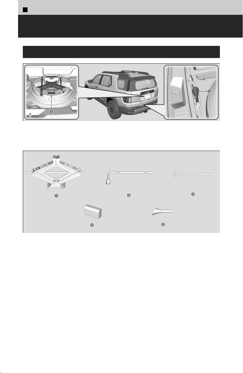
7
Handling the Unexpected >
Tools
Types of Tools
a Tool Case
b Funnel
a Jack
b Wheel Nut Wrench/Jack Handle
c Jack Handle Bar
d Tire Strap/Tire Storage Bag
e Funnel
The tools are stored in the cargo area.
384

7
Handling the Unexpected >
When a lightbulb goes out
About the Vehicle’s LED Exterior Lighting
The following lights are LED lights. Have an authorized Honda dealer inspect and
r
eplace them.
Headlights
Front Turn Signal Lights
Parking/Daytime Running Lights
Front Side Marker Lights
Fog Lights
*
Side Turn Signal/Emergency Indicator Lights
*
Brake Lights
Taillights
Rear Side Marker Lights
High-Mount Brake Light
Back-Up Lights
Puddle Lights
*
Rear License Plate Light
The headlight aim is set by the factory, and does not need to be adjusted. However, if
y
ou regularly carry heavy items in the cargo area or tow a trailer, have the aiming
readjusted at a dealer or by a qualified technician.
Replacing Light Bulbs
Rear Turn Signal Light Bulbs
When replacing, use 21W Amber (
WY21W) bulbs.
a Bolt
[1] Remove the bolts.
[
2] Pull the light assembly out of the rear pillar.
*: Not available on all models
385
7
Handling the Unexpected
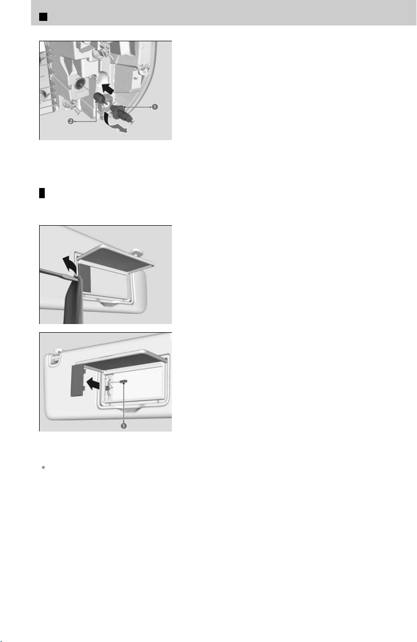
a Socket
b Bulb
[3] Turn the socket counterclockwise and
r
emove it.
[4] Remove the old bulb and insert a new bulb.
[5] Align the pins with the body grommets, then
push in until they fully seat.
Vanity Mirror Light Bulbs
When replacing the light, please use a 2.3W bulb
.
[1] Pry on the edge of the cover using a flat-tip
screwdriver to remove the cover.
a Bulb
[2] Remove the old bulb and insert a new bulb.
Wrap the flat-tip screwdriver with a cloth to prevent scratches.
7
Handling the Unexpected > When a lightbulb goes out
386
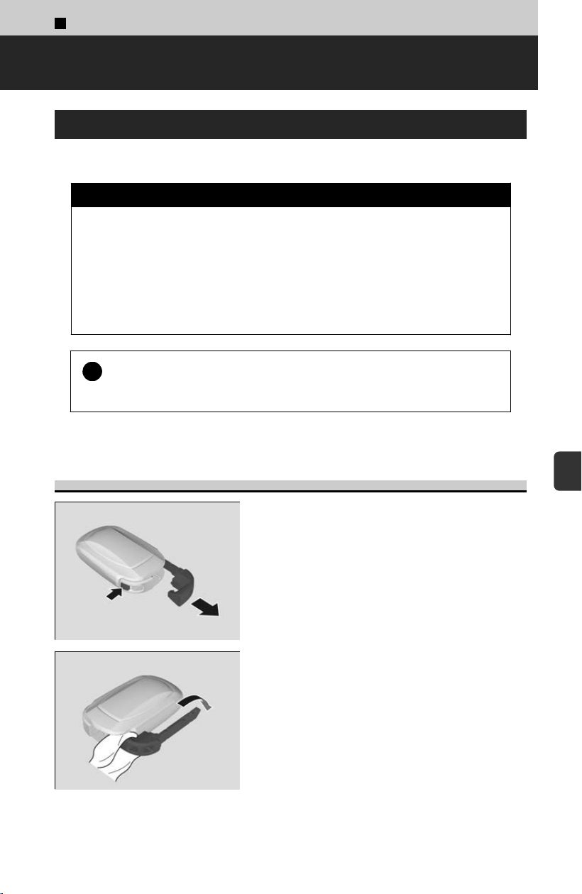
7
Handling the Unexpected >
Remote Transmitter Care
Replacing the Remote Battery
If the indicator does not come on when the button is pressed, replace the battery.
3 WARNING
CHEMICAL BURN HAZARD
The bat
tery that powers the remote transmitter can cause severe internal
burns and can even lead to death if swallowed.
Keep new and used batteries away from children.
If you suspect that a child has swallowed the battery, seek medical
attention immediately.
!
An improperly disposed of battery can damage the environment.
Al
ways confirm local regulations for battery disposal.
Replacement batteries are commercially available or at a dealer.
Keyless Remote
[1] Remove the built-in key.
[2] With the buttons facing down, remove the
upper half o
f the cover by carefully prying on
the slot with the key grip.
387
7
Handling the Unexpected
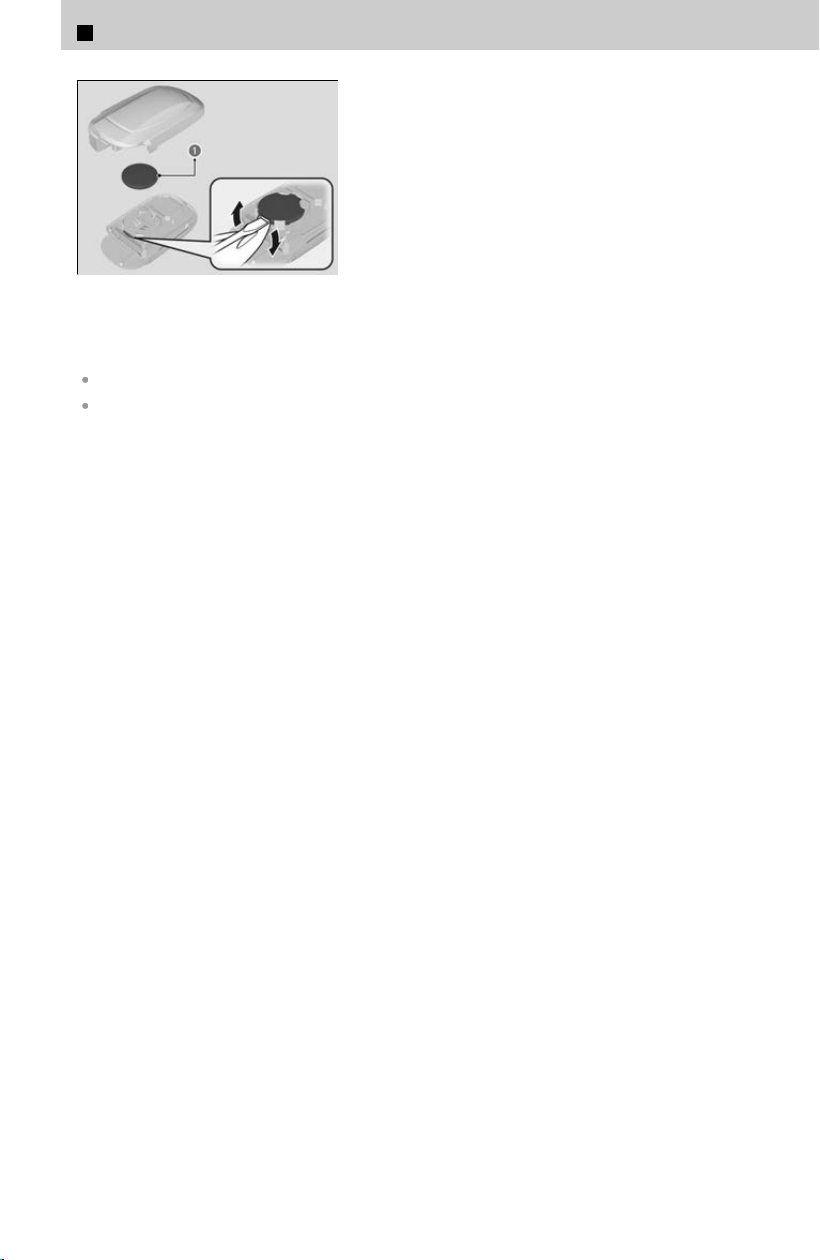
a Battery
[3] Remove the battery by prying on the edge
with flat
-tip screwdriver. Make sure to
replace the battery with the correct polarity.
Battery type: CR2032
Wrap a key grip with a cloth to prevent scratching the keyless remote.
Wrap a flat-tip screwdriver with a cloth to prevent scratching the keyless remote
7
Handling the Unexpected > Remote Transmitter Care
388
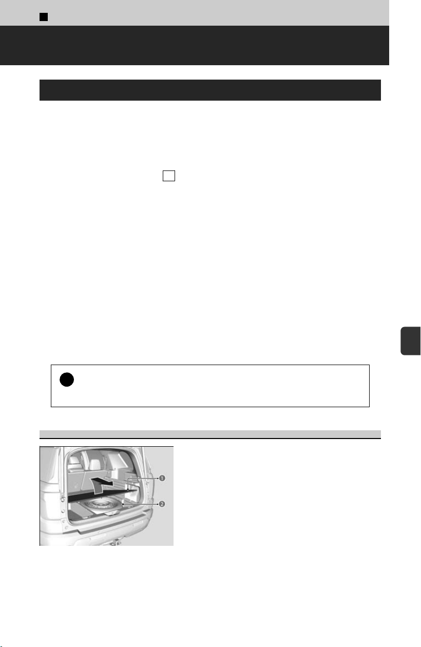
7
Handling the Unexpected >
If a Tire Goes Flat
Changing a Flat Tire
If a tire goes flat while driving, grasp the steering wheel firml
y and brake gradually to
reduce speed. Then, stop in a safe place. Replace the flat tire with a spare tire. Go to a
dealer as soon as possible to have the regular tire repaired or replaced.
[1] Park the vehicle on a firm, le
vel, non-slippery surface and apply the parking
brake.
[2] Put the transmission into P .
[3] Turn on the hazard warning lights and set the power mode to VEHICLE OFF.
Follow compact spare precautions: Periodically check the tire pressure of the
c
ompact spare. It should be set to the specified pressure. Specified Pressure: 60 psi
(420 kPa, 4.2 kgf/cm
2
)
When driving with the compact spare tire, keep the vehicle speed under 50 mph (80
km
/h). Replace with a regular tire as soon as possible.
The compact spare tire and wheel in your vehicle are specifically for this model. Do
not use them with another vehicle. Do not use another type of compact spare tire or
wheel with your vehicle.
Do not mount tire chains on a compact spare tire. If a chain-mounted front tire goes
flat, remove one of the regular rear tires and replace it with the compact spare tire.
Remove the flat front tire and replace it with the regular tire that was removed from
the rear. Mount the tire chains on the front tire.
!
Do not use the jack if it doesn’t work properly.
Cal
l your dealer or a professional towing service.
Getting Ready to Replace the Flat Tire
a Floor Lid
b Compact Spare Tire
[1] Remove the floor lid.
[
2] Unscrew the wing bolt, and remove the
spacer cone. Then, remove the compact
spare tire.
389
7
Handling the Unexpected
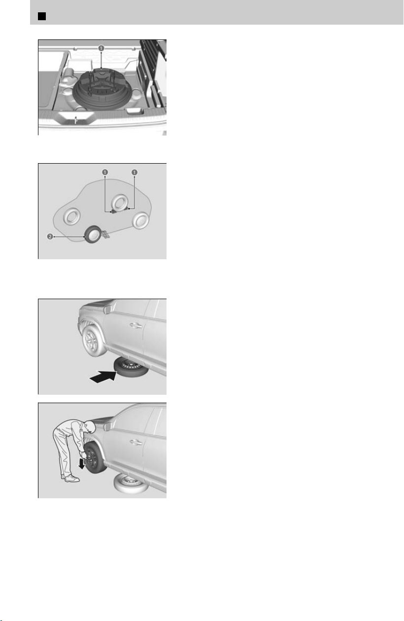
a Tool Case
[3] Take the tool case out of the cargo area.
[
4] Take the jack, wheel nut wrench, jack handle
bar, and tire strap/tire storage bag out of the
tool case.
a Wheel Blocks
b The tire to be replaced.
[5] Place a wheel block or rock in front and rear
o
f the wheel diagonal to the flat tire.
[6] Place the compact spare tire (wheel side up)
under the vehicle body, near the tire that
needs to be replaced.
[7] Loosen each wheel nut about one turn using
the wheel nut wrench.
7
Handling the Unexpected > If a Tire Goes Flat
390
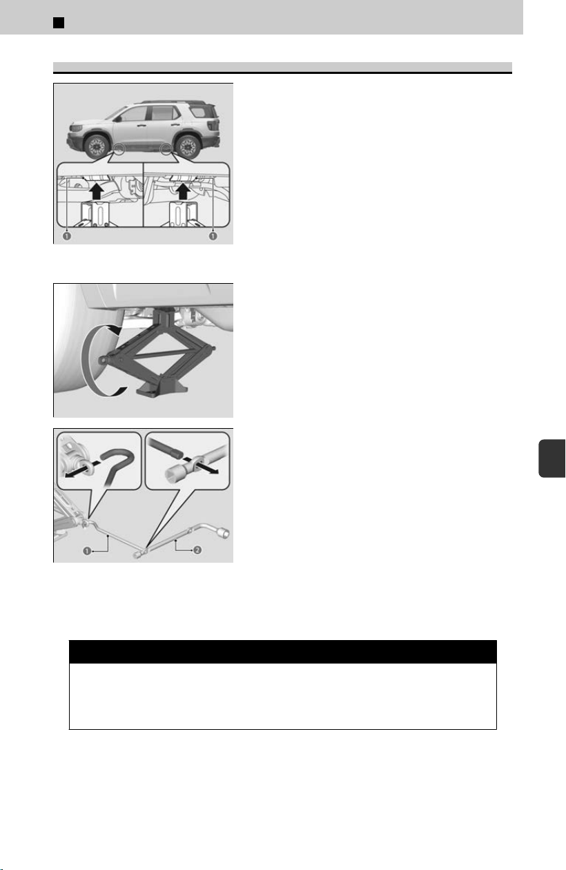
How to Set Up the Jack
a Jacking Points
[1] Place the jack under the jacking point
closes
t to the tire to be changed.
[2] Turn the end bracket clockwise as shown in
the image until the top of the jack contacts
the jacking point.
≫
Make sure that the jacking point tab is resting in
the jack notch.
a Jack Handle Bar
b Wheel Nut Wrench as Jack
Handle
[3] Raise the vehicle, using the jack handle bar
and the jack handle
, until the tire is off the
ground.
3 WARNING
The vehicle can easily roll off the jack, seriously injuring anyone
underneath. F
ollow the directions for changing a tire exactly, and never get
under the vehicle when it is supported only by the jack.
Do not use the jack with people or luggage in the vehicle.
7
Handling the Unexpected > If a Tire Goes Flat
391
7
Handling the Unexpected
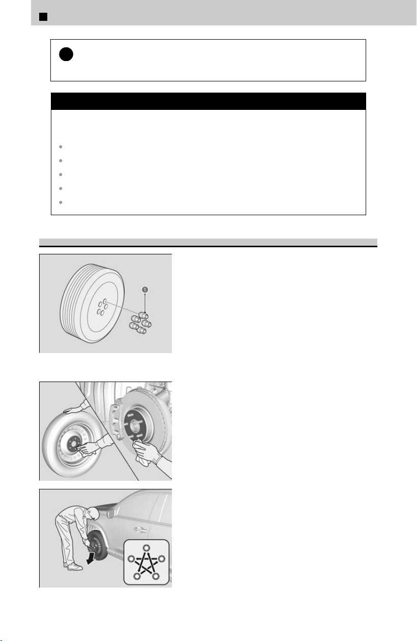
!
Use the jack provided in your vehicle.
Other jack
s may not support the weight (“load”) or may not fit the jacking point.
3 CAUTION
The following instructions must be followed to use the jack
saf
ely:
Do not use while the engine is running.
Use only where the ground is firm and level.
Use only at the jacking points.
Do not get in the vehicle while using the jack.
Do not put anything on top of or underneath the jack.
Replacing the Flat Tire
a Wheel Nut
[1] Remove the wheel nuts and flat tire.
[2] Wipe the mounting surfaces of the wheel
with a clean cloth.
[3] Mount the compact spare tire.
[4] Screw the wheel nuts until they touch the
lips around the mounting holes, then stop
rotating.
[5] Lower the vehicle and remove the jack.
Tighten the wheel nuts in the order indicated
in the image. Go around tightening the nuts
two to three times in this order. Wheel nut
torque: 94 lbf∙ft (127 N∙m, 13 kgf∙m)
7
Handling the Unexpected > If a Tire Goes Flat
392
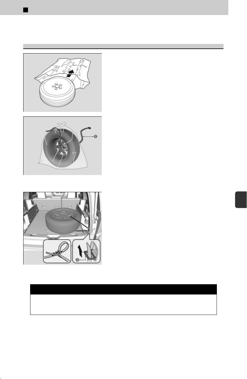
Do not over tighten the wheel nuts by applying extra torque using your foot or a pipe.
Storing the Flat Tire
[1] Put the flat tire in the tire storage bag
provided with your vehicle.
≫
The tire storage bag is in the tool case.
[2] Knot the top of the tire storage bag.
[
3] Securely put the jack, wheel nut wrench,
jack handle bar, and box wrench back in the
tool case.
a Belt
[4] Bore through the bag, and pass the holding
bel
t through the hole of the bag and the
wheel of the flat tire as shown.
a Rear Anchor
[5] Place the flat tire in the cargo area, and
thr
ead the belt through the rear anchor as
shown.
[6] Pass the belt through the ring, and tighten
the belt to secure the flat tire in place.
3 WARNING
Loose items can fly around the interior in a crash and can seriously injure
the oc
cupants. Store the wheel, jack, and tools securely before driving.
7
Handling the Unexpected > If a Tire Goes Flat
393
7
Handling the Unexpected

TPMS and the Compact Spare Tire
If you replace a flat tire with the compact spare tire, the low tire pressure/TPMS
indicat
or will come on while you are driving. After driving for a few miles (kilometers),
the Tire pressure monitor system problem. Check tire pressure. See your dealer.
message will appear on the driver information interface and the indicator will start
blinking for a short time and then stay on; however, this is normal and is no cause for
concern.
If you replace the tire with a genuine tire equipped with low tire pressure/TPMS
sensor, the warning message on the driver information interface and the low tire
pressure/TPMS indicator will go off after a few miles (kilometers).
The system cannot monitor the pressure of the compact spare tire. Manually check
the compact spare tire pressure to be sure that it is correct.
7
Handling the Unexpected > If a Tire Goes Flat
394

7
Handling the Unexpected >
Engine Does Not Start
Checking the Engine
If the engine does not start, check the following items and take appropriate action.
Starter doesn’t turn or turns over slowly.
The battery may be dead. Check each of the items below and respond accordingly.
Check for a message on the driver information interface.
If the To start, touch start button with emblem side of remote message appears, use the
keyless remote to turn on the power or start the engine.
If the Keyless Remote Battery is Weak
u
P.396
Check the fuses.
Check all fuses, or have your vehicle checked by a dealer.
Inspecting and Changing Fuses
u
P.407
Starter turns over normally but the engine doesn’t start.
There may be a problem with a fuse. Check each of the items below and respond
ac
cordingly.
Review the engine start procedure.
Follow its instructions, and try to start the engine again.
Starting the Engine
u
P.111
Check the immobilizer system indicator.
When the immobilizer system indicator is blinking, the engine cannot be started.
Immobilizer System
u
P.48
Check the fuel level.
There should be enough fuel in the tank.
Fuel Gauge
u
P.331
Check the fuses.
Check all fuses, or have your vehicle checked by a dealer.
Inspecting and Changing Fuses
u
P.407
If the problem continues:
About Towing
u
P.409
If you must start the vehicle immediately, use an assisting vehicle or booster battery to
jump start it.
Jump Starting Procedure
u
P.397
Depending on the situation, it may be possible to temporarily start the engine using the
emergency starting procedure.
395
7
Handling the Unexpected
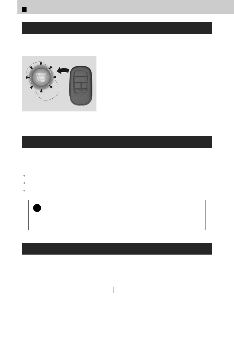
If the Keyless Remote Battery is Weak
Follow the steps below if the ENGINE S
TART/STOP button does not turn on the
power or start the engine.
[1] Press the ENGINE START/STOP button.
[2] Touch the center of the ENGINE START/
STOP button with the keyless remote within
30 seconds. The buttons on the keyless
remote should be facing you.
[3] Depress and hold the brake pedal, then
press the ENGINE START/STOP button
within 10 seconds.
≫
If you don’t depress the pedal, the mode will
change to ACCESSORY.
Emergency Engine Stop
The ENGINE S
TART/STOP button may be used to stop the engine due to an
emergency situation even while driving. If you must stop the engine, do either of the
following operations:
Press and hold the ENGINE START/STOP button for about two seconds.
Firmly press the ENGINE START/STOP button three times.
The steering wheel will not lock.
!
If the power mode is set to ACCESSORY while driving, the engine will
shut do
wn and all steering and brake power assist functions will stop,
making it difficult to control the vehicle.
Emergency Engine Start
If the engine cannot start using the normal starting procedure, you may be able to
s
tart it using the emergency starting procedure below.
Do not use this procedure if it is not an emergency.
[1] Make sure the parking brake is applied.
[
2] Check that the transmission is in P , then set the power mode to ACCESSORY.
[3] Firmly depress the brake pedal, then press and hold the ENGINE START/STOP
button for at least 15 seconds.
This should be considered a system malfunction even if you are able to start the
engine using the abo
ve procedure.
Have your vehicle checked by a dealer immediately.
7
Handling the Unexpected > Engine Does Not Start
396
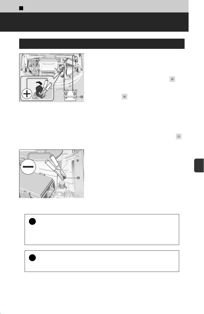
7
Handling the Unexpected >
If the 12-volt Battery Is Dead
Jump Starting Procedure
a Assisting Vehicle’s Battery
[1] Turn off the power to electric devices, such
as audio and lights
.
[2] Set your vehicle and the assisting vehicle’s
power modes to OFF.
[3] Connect the first jumper cable to the
terminal of your vehicle’s 12-volt battery.
[4] Connect the other end of the first jumper
cable to the terminal of the assisting
vehicle’s battery (a).fully.
≫
Use a 12-volt booster battery only.
≫
When using an automotive battery charger to
boost your 12-volt battery, select a lower
charging voltage than 15-volt. Check the
charger manual for the proper setting.
[5] Connect the second jumper cable to the
terminal of the assisting vehicle’s battery.
b Ground Bolt
[6] Connect the other end of the second jumper
cable t
o your vehicle’s ground bolt (b).
[7] Start the assisting vehicle’s engine and
increase its RPM slightly.
[8] Start your vehicle’s engine.
!
Securely attach the jumper cables clips so that they do not come off
when the engine vibr
ates.
Be careful not to tangle the jumper cables or allow the cable ends to touch
each other while attaching or detaching the jumper cables.
!
12-volt battery performance degrades in cold conditions and may
pr
event the engine from starting.
397
7
Handling the Unexpected
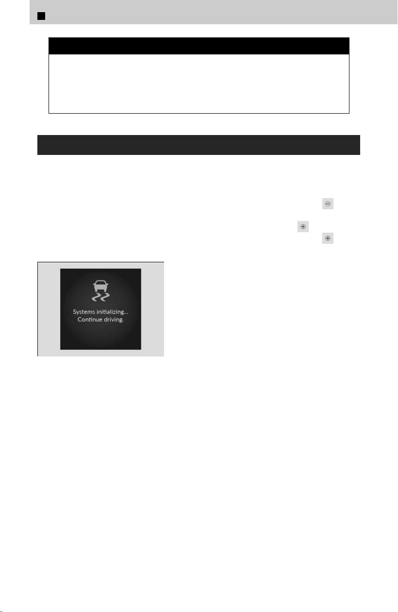
3 WARNING
A 12-volt battery can explode if you do not follow the correct procedure,
seriousl
y injuring anyone nearby.
Keep all sparks, open flames, and smoking materials away from the 12-volt
battery.
What to Do After the Engine Starts
Once your vehicle’s engine has started, remove the jumper cables in the following
or
der.
[1] Disconnect the jumper cable from your vehicle’s ground.
[
2] Disconnect the other end of the jumper cable from the booster battery
terminal.
[3] Disconnect the jumper cable from your vehicle’s 12-volt battery terminal.
[4] Disconnect the other end of the jumper cable from the booster battery
terminal.
After re-connecting the 12-volt battery: if various
indicators come on and the message on the left is
displayed on the driver information interface, with
the engine running, turn the steering wheel to the
left until it stops then to the right until it stops,
then drive a short distance at more than 12 mph
(20 km/h). If the indicator does not go off, have
your vehicle checked by a dealer.
7
Handling the Unexpected > If the 12-volt Battery Is Dead
398
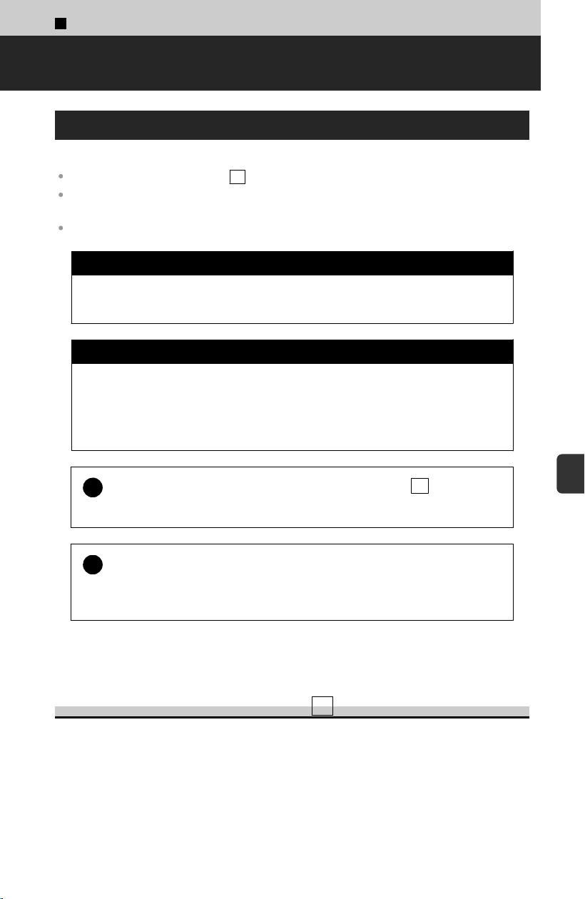
7
Handling the Unexpected >
Overheating
How to Handle Overheating
Overheating symptoms are as follows:
The temperature gauge is at the H mark or the engine suddenly loses power.
The Engine temperature too hot. Do not drive. Allow engine to cool. message appears on
the driver information interface.
Steam or spray comes out of the engine compartment.
3 WARNING
Steam and spray from an overheated engine can seriously scald you.
Do not open the hood if s
team is coming out.
3 WARNING
Removing the radiator cap while the engine is hot can cause hot coolant to
spr
ay out, seriously scalding you.
Always let the engine and radiator cool down before removing the radiator
cap.
!
Continuing to drive with the temperature gauge at the H
mark may
damage the engine.
!
Continuing to drive with the Engine t
emperature too hot. Do not
drive. Allow engine to cool. message on the driver information
interface may damage the engine.
Use water as an emergency/temporary measure only. Have a dealer flush the system
with proper antifreeze as soon as possible.
The temperature gauge is at the H mark
[1] Immediately park the vehicle in a safe place.
[
2] Turn off all accessories and turn on the hazard warning lights.
≫
No steam or spray present: Keep the engine running and open the hood.
≫
Steam or spray is present: Turn off the engine and wait until it subsides. Then, open the
hood.
399
7
Handling the Unexpected
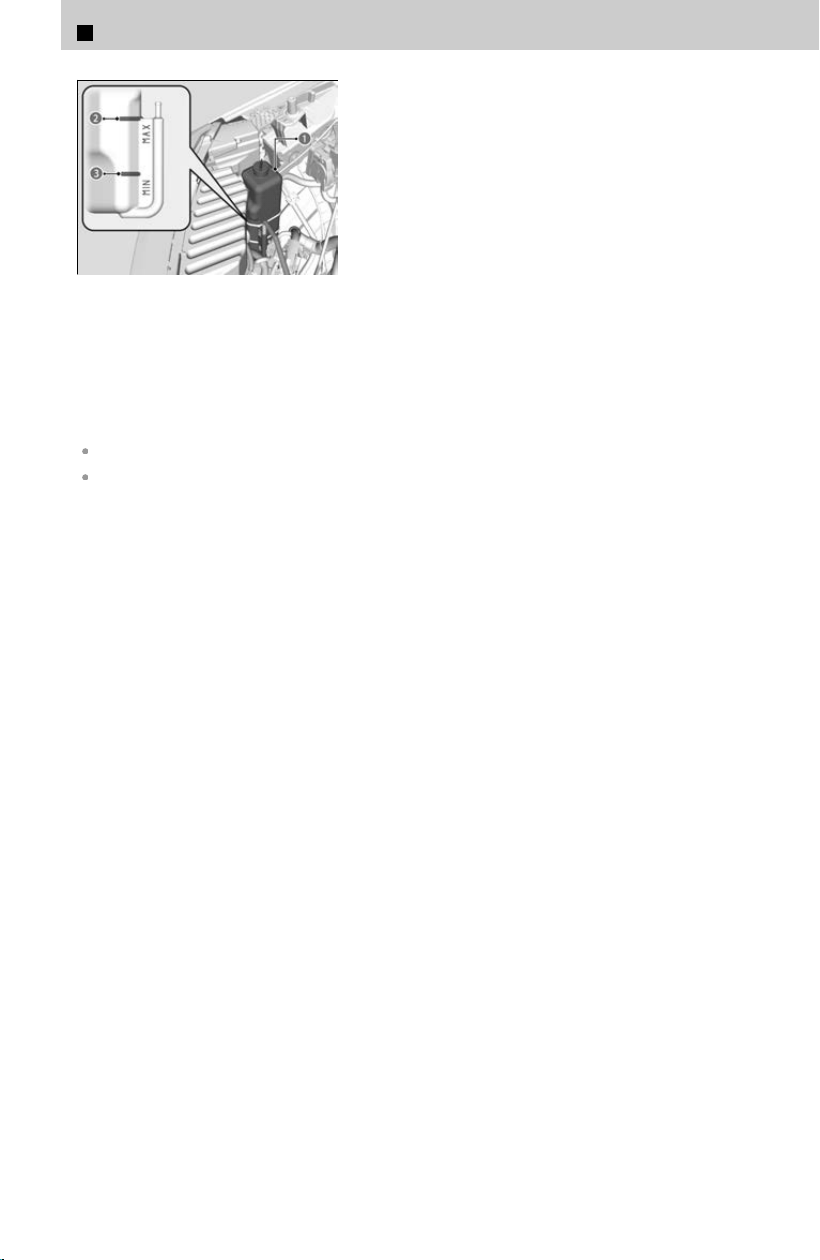
a Reserve Tank
b MAX
c MIN
[3] Check that the cooling fan is operating and
s
top the engine once the temperature gauge
goes down.
≫
If the cooling fan is not operating, immediately
stop the engine.
[4] Once the engine has cooled down, inspect
the c
oolant level and check the cooling
system components for leaks.
≫
If the coolant level in the reserve tank is low,
add coolant until it reaches the MAX mark.
≫
If there is no coolant in the reserve tank, check
that the radiator is cool. Cover the radiator cap
with a heavy cloth and open the cap. If
necessary, add coolant up to the base of the
filler neck, and put the cap back on.
If the temperature gauge does not go down, have your vehicle inspected at a dealer.
If the coolant is leaking, contact a dealer for repairs.
7
Handling the Unexpected > Overheating
400
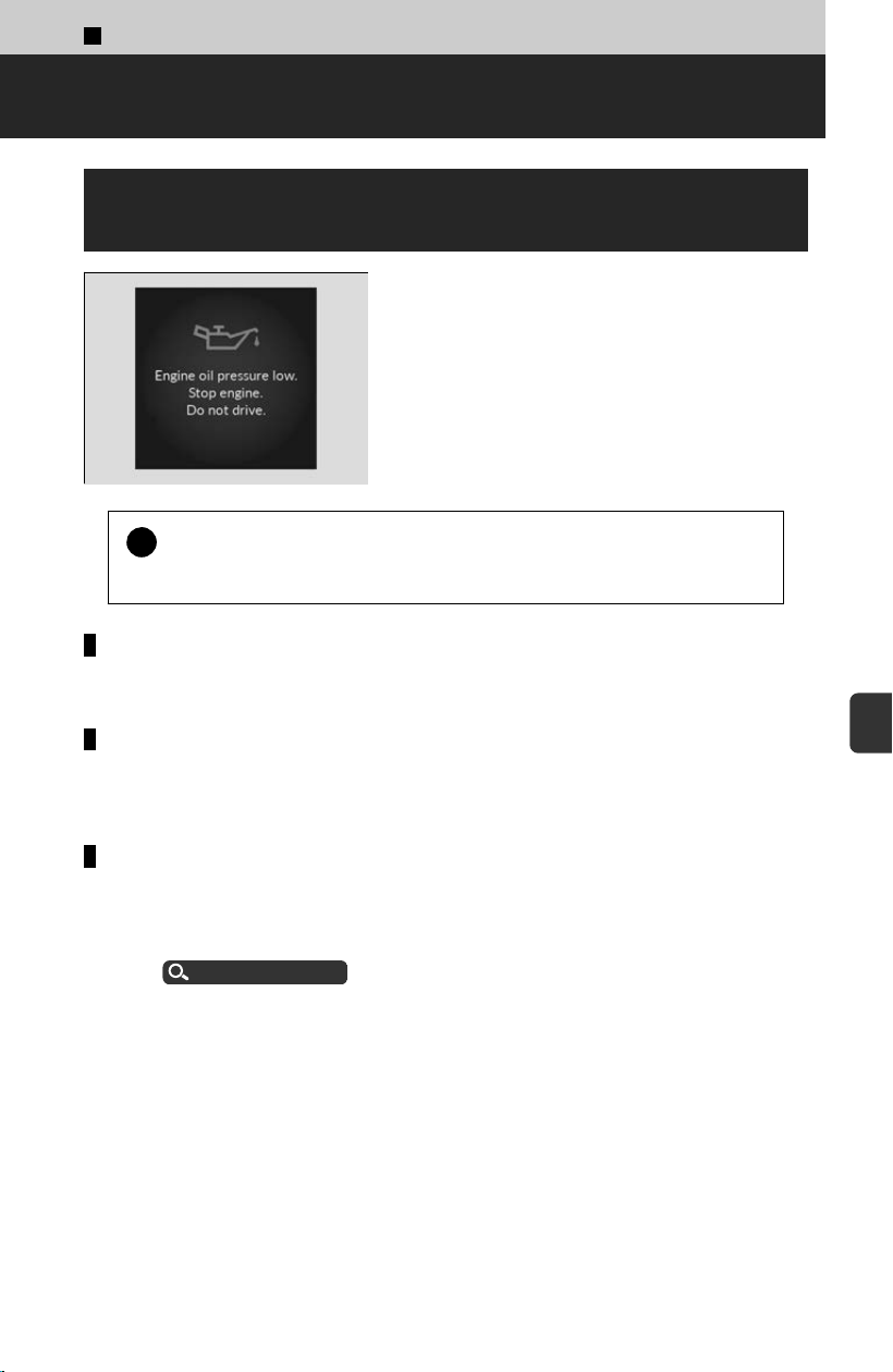
7
Handling the Unexpected >
When a Warning Appears
If the Engine oil pressure low Warning
Appears
!
Running the engine with low oil pressure can cause serious
mechanical damag
e almost immediately.
Reasons for the warning to appear
Appears when the engine oil pressure is low.
What to do as soon as the warning appears
[1] Immediately park the vehicle on level ground in a safe place.
[2] If necessary, turn the hazard warning lights on.
What to do after parking the vehicle
[1] Stop the engine and let it sit for approximately three minutes.
[2] Open the hood and check the oil level.
≫
Add oil as necessary.
Oil Check
u
P.355
[3] Start the engine and check the Engine oil pr
essure low warning.
≫
The warning disappears: Start driving again.
≫
The warning does not disappear within 10 seconds: Immediately stop the engine and
contact a dealer for repairs.
401
7
Handling the Unexpected
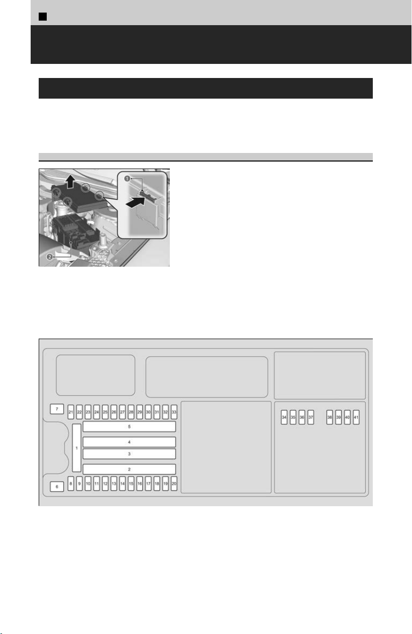
7
Handling the Unexpected >
Fuses
Checking Fuses
If any electrical devices are not working, set the power mode to VEHICLE OFF and
check t
o see if any applicable fuse is blown.
Engine Compartment Fuse Box
a Tab
b Fuse Box
Located at the engine compartment on the left
side
.
≫
Push the tabs (a) to open the box.
Fuse locations are shown on the fuse box cover, or the image below. Locate the fuse
in ques
tion by the fuse number.
402
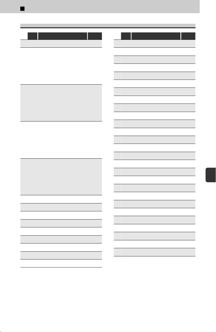
Circuit Protected and Fuse Rating
Circuit Protected Amps
1 - BATTERY 225A
2
-
-
-
-
-
-
-
IDLE STOP 1
IDLE S
TOP 2
EPS
FET MAIN 1
FUSE BOX MAIN 1
FUSE BOX OP 1
RR BLOWER
30A
30A
80A
70A
60A
60A
30A
3
-
-
-
-
-
-
-
ACM
S
TARTER CUT
-
RAD FAN 1
ACC SOCKET MAIN
RR DEF
FUSE BOX OP 2
30A
30A
-
40A
40A
40A
60A
4
-
-
-
-
-
-
-
EBB
PT
G
-
HEATER MTR
ABS/VSA FSR
AC INVERT
*
FUSE BOX MAIN 2
40A
40A
-
40A
40A
(30A)
60A
5
-
-
-
-
-
-
-
FET MAIN 2
ABS
/VSA MOTOR
IG MAIN 2
SRM 2
SRM 1
4WD
IG MAIN 1
30A
40A
30A
30A
30A
30A
30A
6 - RAD FAN 2 40A
7 - WIPER MOTOR 30A
8 - PTG 20A
9 -
ICB SUB
*
(20A)
10 - RFC RELAY 10A
11 - BACK UP 10A
12 -
Trailer Battery
*
(20A)
13 -
Trailer Electric Brake
*
(20A)
14 - HORN 15A
Circuit Protected Amps
15 -
Trailer Backup Lamps
*
(10A)
16 - VBU 10A
17 - - -
18 -
Trailer Parking Lamps
*
(30A)
19 - FI MAIN 20A
20 - INJ 20A
21 - TCU 1 15A
22 - IG COIL 15A
23 - HAZARD 10A
24 - R H/L 15A
25 - STOP 5A
26 - L H/L 15A
27 - TCU 3 10A
28 - TCU 2 10A
29 - - -
30 -
Trailer Stop/Turn Lamps
*
(10A)
31 - FR WASHER 15A
32 - BATT SNSR 10A
33 - SHUTTER GRILLE 10A
34 - IG1 START 5A
35 - BATT FAN 5A
36 - FI ECU 5A
37 - - -
38 - IG1 PCS 5A
39 - IGPS VSSV 10A
40 - - -
41 - - -
*: Not available on all models
7
Handling the Unexpected > Fuses
403
7
Handling the Unexpected
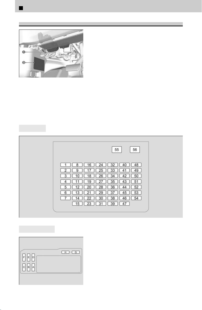
Driver’s Side Interior Fuse Box
a Fuse Box
b Sub Fuse Box
c Label
*
Located under the dashboard.
Fuse locations are shown on the label on the side panel, or the image below. Locate
the fuse in ques
tion by the fuse number.
4
Fuse Box
4
Sub Fuse Box
*: Not available on all models
7
Handling the Unexpected > Fuses
404
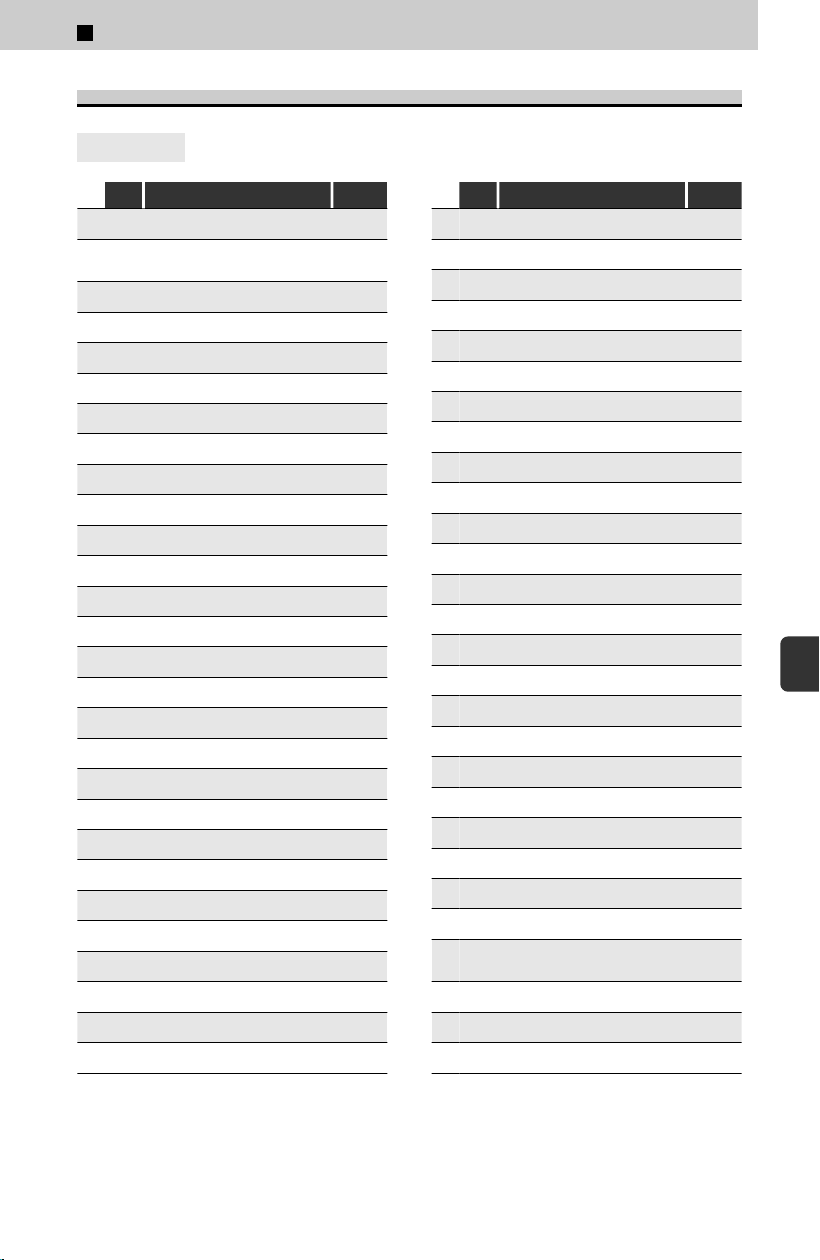
Circuit Protected and Fuse Rating
4
Fuse box
Circuit Protected Amps
1 - DRIVER POWER WINDOW 30A
2 -
PASSENGER POWER
WINDO
W
30A
3 - REAR R POWER WINDOW 30A
4 - REAR L POWER WINDOW 30A
5 - OPTION 10A
6 - SRS 10A
7 - - -
8 - - -
9 -
REAR ACCESSORY
*
(20A)
10 - DOOR LOCK MAIN 20A
11 - METER 10A
12 - TRANSMISSION 10A
13 - REAR WIPER 10A
14 - - -
15 - DRIVER DOOR UNLOCK 10A
16 -
SUNROOF
*
(20A)
17 - - -
18 -
HAC ACCESSORY
*
(20A)
19 - ALL WHEEL DRIVE 10A
20 - DISPLAY 10A
21 - - -
22 - SMART ENTRY 10A
23 - DRIVER DOOR LOCK 10A
24 - - -
25 - SHIFTER 10A
26 - SRS 10A
27 - ACG 15A
28 - VSA/ABS 10A
Circuit Protected Amps
29 - FUEL PUMP 20A
30 - LEFT DOOR UNLOCK 10A
31 - RIGHT DOOR UNLOCK 10A
32 -
SUNSHADE
*
(20A)
33 - CGW 10A
34 - - -
35 - FRONT USB CHARGE 10A
36 - REAR USB CHARGE 10A
37 - - -
38 - - -
39 - RIGHT DOOR LOCK 10A
40 - DRIVER SEAT SLIDE 20A
41 - DRIVER SEAT RECLINE 20A
42 - STARTER 10A
43 - AIRCON 10A
44 - DRL 10A
45 - ACCESSORY 10A
46 - - -
47 - LEFT DOOR LOCK 10A
48 - - -
49 - PASSENGER SEAT SLIDE 20A
50 - DRIVER SEAT LUMBAR 10A
51 - - -
52 - - -
53 -
PASSENGER SEAT
RECLINE
20A
54 - - -
55 -
AUDIO AMP
*
(30A)
56 - - -
*: Not available on all models
7
Handling the Unexpected > Fuses
405
7
Handling the Unexpected
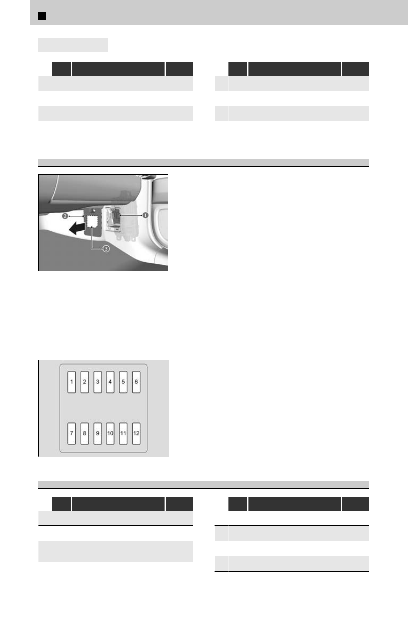
4
Sub fuse box
Circuit Protected Amps
A - OPTION 10A
B - ACCESSORY 10A
C - AUDIO 15A
D -
MVC
*
(10A)
Circuit Protected Amps
E - AUDIO 20A
F - - -
G - METER 15A
H - MICU 10A
Passenger’s Side Interior Fuse Box
a Fuse Box
b Cover
c Label
*
Located on the lower side panel. Take off the
c
over to open.
Fuse locations are shown on the fuse box cover, or the image below. Locate the fuse
in ques
tion by the fuse number.
Circuit Protected and Fuse Rating
Circuit Protected Amps
1 − − −
2 − A/C COMPRESSOR 10A
3 −
HEATED STEERING
WHEEL
*
(10A)
Circuit Protected Amps
4 −
FR DEICER
*
(15A)
5 −
FRONT FOG LIGHTS
*
(10A)
6 − FI SUB 15A
7 − FRONT HEATED SEAT 20A
*: Not available on all models
7
Handling the Unexpected > Fuses
406
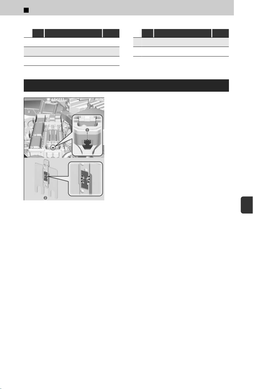
Circuit Protected Amps
8 − − −
9 − − −
10 −
REAR HEATED SEAT
*
(20A)
Circuit Protected Amps
11 − − −
12 − FRONT ACC SOCKET 20A
Inspecting and Changing Fuses
a Hole
b Main Fuse
[1] Set the power mode to VEHICLE OFF. Turn
headlights and al
l accessories off.
[2] Remove the fuse box cover.
[3] Check the main fuse in the engine
compartment fuse box.
≫
Look at the fuse through the hole.
≫
If the fuse is blown, have it replaced by a dealer.
*: Not available on all models
7
Handling the Unexpected > Fuses
407
7
Handling the Unexpected
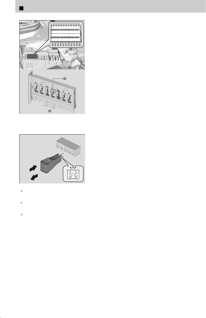
a Blown Fuse
b Combined Fuse
[4] Check the combined fuses in the engine
c
ompartment fuse box.
≫
Look into the space between the fuses.
≫
If the fuse is blown, have it replaced by a dealer.
[5] Inspect the small fuses in the engine
compartment and the vehicle interior.
≫
If there is a blown fuse, remove it with the fuse
puller and replace it with a new one.
Replacing a fuse with one that has a higher rating greatly increases the chances of damaging
the electrical system.
Use the charts to locate the fuse in question and confirm the specified amperage on the fuse
label.
Replace with a fuse of the same specified amperage.
There is a fuse puller on the back of the engine compartment fuse box cover.
7
Handling the Unexpected > Fuses
408
7
Handling the Unexpected >
Emergency Towing
About Towing
Call a professional towing service if you need to tow your vehicle.
Trying to lift or tow your vehicle by the bumpers will cause serious damage. The bumpers are
not designed to support the vehicle’s weight.
!
Never tow your vehicle with just a rope or chain.
It is v
ery dangerous since ropes or chains may shift from side to side or break.
!
Improper towing such as towing behind a motorhome or other motor
v
ehicle can damage the transmission.
Flatbed equipment
The operator loads your vehicle on the back of a truck.
This is the only way you can safely transport your vehicle.
Any other towing method will damage the vehicle’s drive system.
409
7
Handling the Unexpected
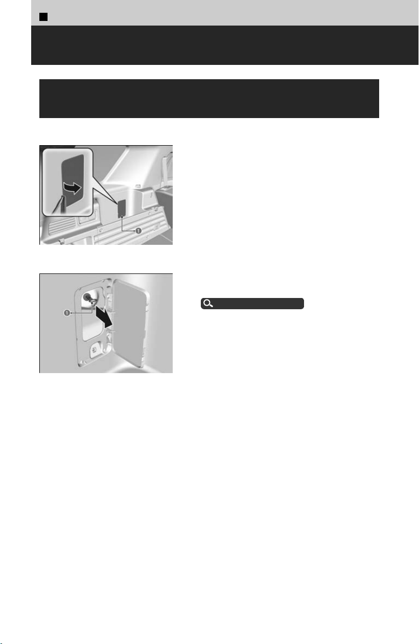
7
Handling the Unexpected >
If You Cannot Unlock the Fuel Fill Door
What to Do If Unable to Unlock the Fuel Fill
Door
If you cannot unlock the fuel fil
l door, use the following procedure.
a Cover
[1] Open the tailgate.
[
2] Use a flat-tip screwdriver and open the
cover.
≫
Wrap the flat-tip screwdriver with a cloth to
prevent scratches.
a Release Cord
[3] Pull the release cord as shown.
[
4] Open the fuel fill door.
How to Refuel
u
P.142
After taking these steps, contact a dealer to have the vehicle checked.
410
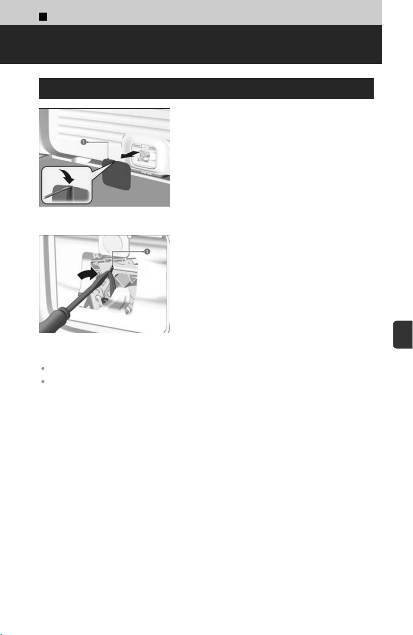
7
Handling the Unexpected >
If You Cannot Open the Tailgate
What to Do If Unable to Open the Tailgate
a Cover
[1] Use a flat-tip screwdriver and remove the
c
over on the back of the tailgate.
a Screwdriver
[2] To open the tailgate, push the tailgate while
pushing the le
ver to the right with the flat-tip
screwdriver.
Wrap the flat-tip screwdriver with a cloth to prevent scratches.
Following up:
After taking these steps, contact a dealer to have the vehicle checked.
411
7
Handling the Unexpected
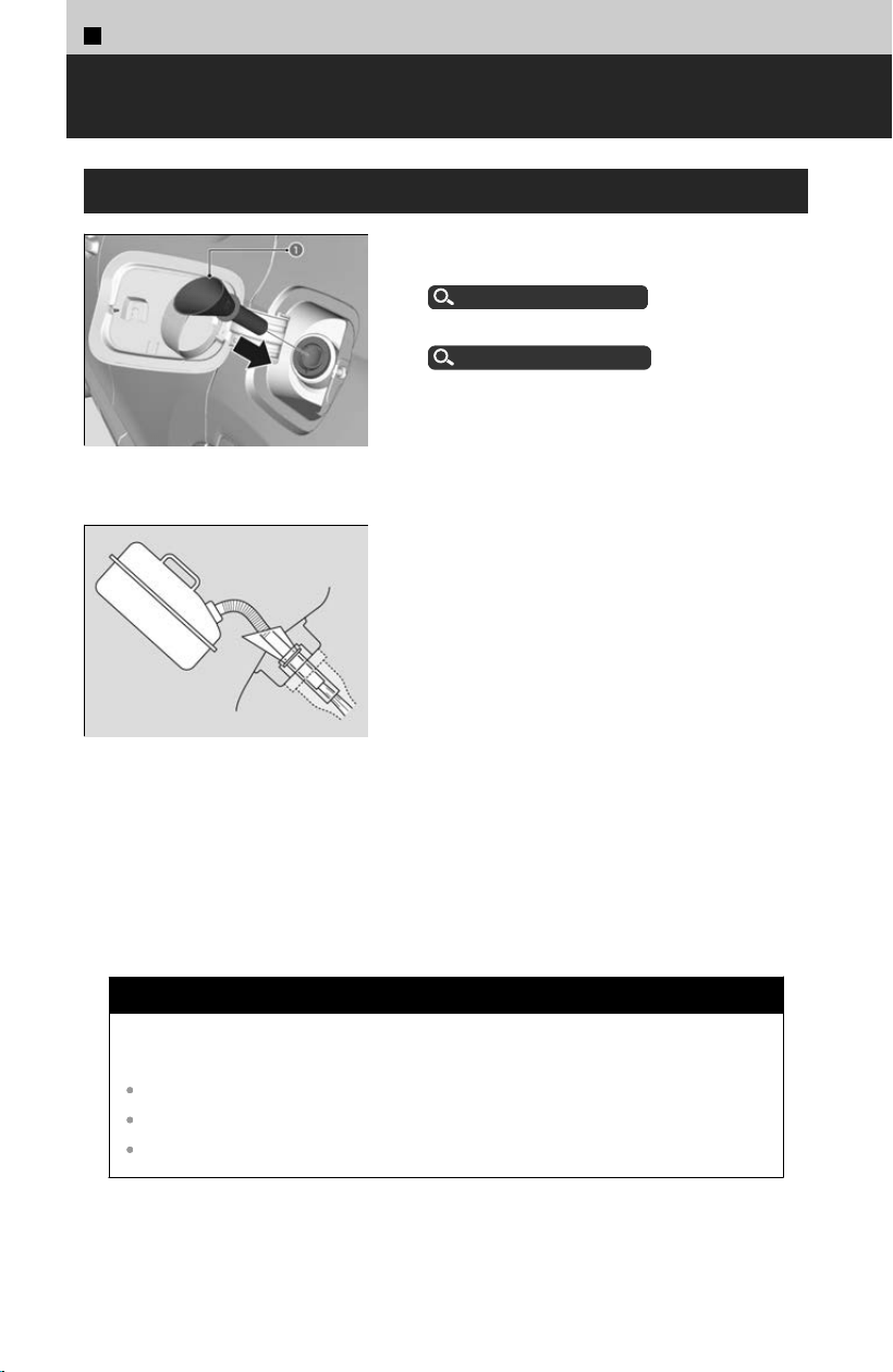
7
Handling the Unexpected >
Refueling
Refueling From a Portable Fuel Container
a Funnel
[1] Turn off the engine.
[
2] Open the fuel fill door.
How to Refuel
u
P.142
[3] Take the funnel out of the cargo area.
Types of Tools
u
P.384
[4] Place the end of the funnel on the lower part
o
f filler opening, then insert it slowly and
fully.
≫
Make sure that the end of the funnel goes down
along with the filler pipe.
[5] Fill the tank with fuel from the portable fuel
c
ontainer.
≫
Pour fuel carefully so you do not spill any.
[6] Remove the funnel from the fil
ler neck.
≫
Wipe up any fuel from the funnel before storing
it.
[7] Shut the fuel fil
l door by hand.
Do not insert the nozzle of a portable fuel container or any funnel other than the one
pr
ovided with your vehicle. Doing so can damage the fuel system.
Do not try to pry open or push open the sealed fuel tank with foreign objects. This can
damage the fuel system and its seal.
Make sure the fuel in the portable fuel container is gasoline before you refuel.
3 WARNING
Gasoline is highly flammable and explosive.
Y
ou can be burned or seriously injured when handling fuel.
Stop the engine, and keep heat, sparks, and flames away.
Handle fuel only outdoors.
Wipe up spills immediately.
412
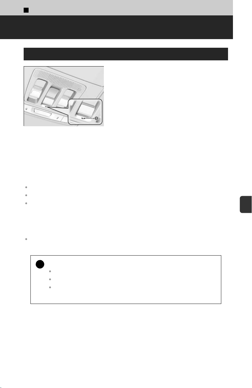
7
Handling the Unexpected >
Emergency Call (eCall)
Automatic Emergency Call
a eCall Indicator
If your vehicle is involved in a collision, the
v
ehicle will attempt to connect to an operator.
Once a connection is established, your location
information will be sent to an operator with whom
you will be able to speak.
When an emergency call is initiated, the vehicle speakers are disabled so that you can
hear the oper
ator.
When the power mode is set to ON, the eCall indicator lights up in green for 1 second,
then in red for 1 second.
If the eCall system is working properly, the indicator will light up in green.
Green: eCall system is ready.
Blinking in green: eCall system is connected and making an eCall to an operator.
Repeating a pattern of short flashes of the red light: The eCall system has failed to connect to
an operator. The eCall indicator will continue this pattern for five seconds, then it will light up
in green.
If the eCall system is disabled in the event of a critical system failure, the following
w
arning will be given to the occupants of the vehicle:
Red or blacked out: A problem with the eCall system has occurred. If the indicator stays red or
blacked out even after you have restarted the vehicle, have the system check by a dealer.
!
Your vehicle may NOT be able to connect to an operator if:
The 12V battery is too low.
Your vehicle is in an area without adequate cellular coverage.
There is a problem with the eCall system itself or its peripheral equipment
such as the microphone or speakers.
413
7
Handling the Unexpected
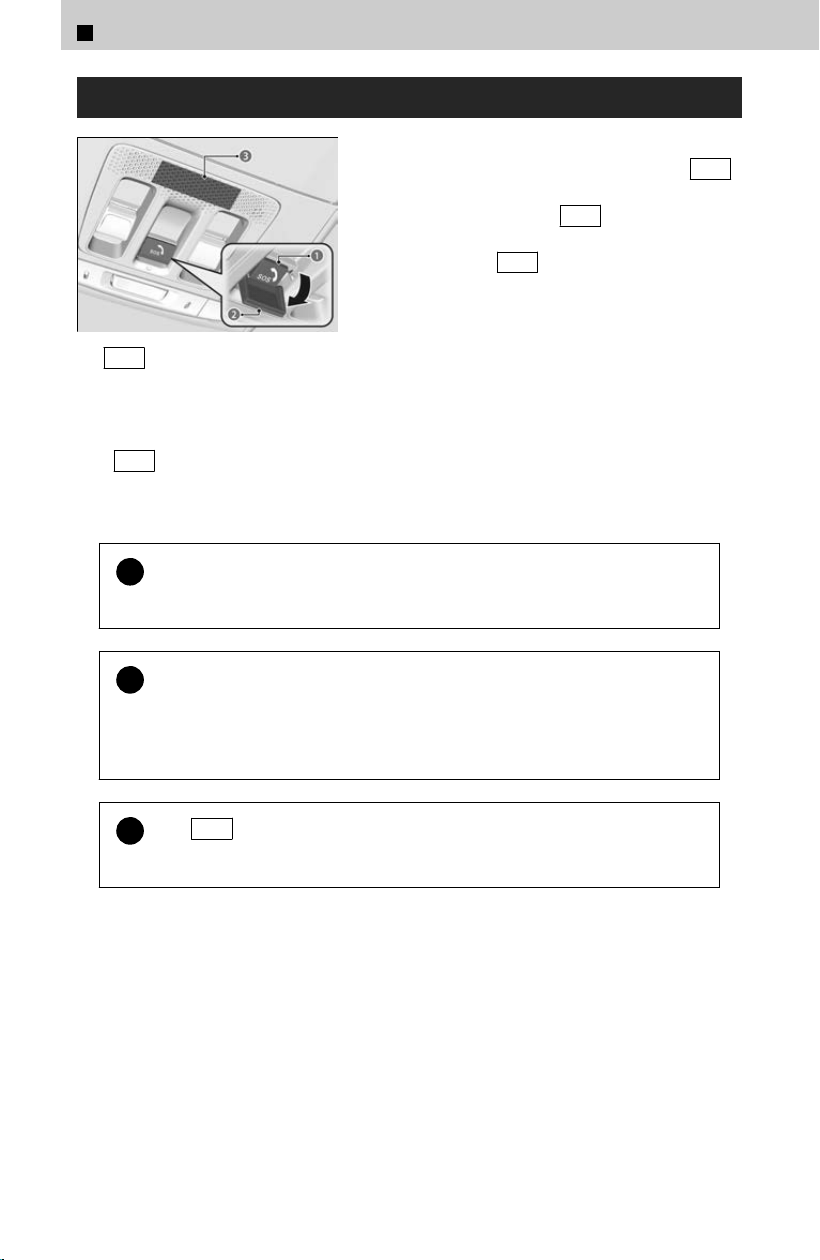
Manual Emergency Call
a SOS Button
b Cover
c Microphone
If you need to make an emergency call, you can
es
tablish a connection manually. Press the SOS
button.
To cancel a call, press the SOS button for more
than two seconds, before 10 seconds have
elapsed since the SOS button was pressed.
The SO
S button is protected by a cover. Open the cover to gain access.
When an emergency call is initiated, the vehicle speakers are disabled so that you can
hear the operator.
!
Do NOT press the button while you are driving. If you need to contact
an oper
ator, park the vehicle in a safe place before you make a call.
!
If the eCall system at firs
t fails to connect to an operator, it will try
again until a connection is established. However, if two minutes have
elapsed since the first try was attempted, the system will no longer
attempt to establish a connection.
!
The SO
S button does not cancel a call once the system is connected
to an operator.
7
Handling the Unexpected > Emergency Call (eCall)
414

Specifications
About Specifications・・・・・・・・・・・・・・・・・・・・・・・・・・・416
Identification Numbers
Vehicle Identification Number (VIN), Engine
Number and Transmission Number・・・・・・・・・・ 418
Devices that Emit Radio Waves
About Devices that Emit Radio Waves・・・・・・・・・ 419
Reporting Safety Defects
About Reporting・・・・・・・・・・・・・・・・・・・・・・・・・・・・・・・ 420
Emissions Testing
Testing of Readiness Codes・・・・・・・・・・・・・・・・・・・ 422
Warranty Coverages
About Warranty Coverages・・・・・・・・・・・・・・・・・・・・ 424
Authorized Manuals
If necessary・・・・・・・・・・・・・・・・・・・・・・・・・・・・・・・・・・・ 426
Customer Service Information
Contacts・・・・・・・・・・・・・・・・・・・・・・・・・・・・・・・・・・・・・・・ 427
Open Source License
Summary・・・・・・・・・・・・・・・・・・・・・・・・・・・・・・・・・・・・・・ 429
Vehicle Information
415

8
Vehicle Information >
Specifications
About Specifications
Basic Information
Model Passport
No. of Passengers:
Front 2
Rear 3
Total 5
Weights:
Gross Vehicle
W
eight Rating
See the certification label
on the driver’s doorjamb
Gross Axle Weight
R
ating (Front)
See the certification label
on the driver’s doorjamb
Gross Axle Weight
R
ating (Rear)
See the certification label
on the driver’s doorjamb
Gross Combined
W
eight Rating
U.S.:
10,163 lbs (4,610 kg)
Canada: 4,610 kg
Air Conditioning
Refrigerant
T
ype
HFO-1234yf (R-1234yf)
Charge
Quantity
21.3-23.1 oz (605-655 g)
Lubricant Type RB100EV-01 (POE)
Quantity
10.28-11.41 cu-in (168.5-187.1
cm
3
)
Engine Specifications
Displacement
211.7 cu-in (3,471 cm
3
)
Spark Plugs NGK
DILZKAR7H11
H
Fuel
Type
Unleaded gasoline, pump
octane number 87 or
higher
Fuel Tank Capacity 18.5 US gal (70.0 L)
Washer Fluid
Tank Capacity
U.S.:2.6 US qt (2.5 L
)
*1
4.8 US qt (4.5 L)
*2
Canada:4.8 US qt (4.5 L)
*1: Models without multi view camera system
*2: Models with multi view camera system
Light Bulbs
Headlights (Low Beam) LED
Headlights (High Beam) LED
Front Turn Signal/Parking/
Daytime Running Lights
LED
Front Side Marker Lights LED
Fog Lights
*
LED
Side Turn Signal Lights (on
Door Mirr
ors)
*
LED
Brake Lights LED
Taillights LED
Rear Turn Signal Lights
21 W Amber
(
WY21W)
Rear Side Marker Lights LED
Back-Up Lights LED
High-Mount Brake Light LED
Rear License Plate Light LED
Puddle Lights
*
LED
Interior Lights
Front and Rear
Map Lights
LED
Cargo Area
Lights
LED
Vanity Mirror
Lights
2.3 W
Instrument
P
anel Tray
Lights
LED
Glove Box
Light
LED
Door Courtesy
Lights
*
LED
Door Pocket
Lights
*
LED
Foot Lights
*
LED
Door Inner
Handle Lights
*
LED
Ambient
Lights
LED
Brake Fluid
Specified
Honda Heavy Duty Brake
Fluid DO
T 3
*: Not available on all models
416

Automatic Transmission Fluid
Specified Honda ATF-type 2.0
Capacity Change
4.4 US qt (4.2
L
)
Rear Differential Fluid
Specified Honda DPSF-II
Capacity Change
1.76 US qt
(1.67 L
)
Transfer Assembly Fluid
Specified Honda HGO-1
Capacity Change
0.58 US qt
(0.55 L
)
Engine Oil
Recommended
•
Honda Genuine Motor Oil
0W-20
•
API service SN or higher grade
0W-20
Capacity Change
5.5 US qt (5.2
L
)
Capacity
Change
including fil
ter
5.8 US qt (5.5
L)
Engine Coolant
Specified
Honda Long Life
Antifr
eeze/Coolant Type 2
Ratio 50/50 with distilled water
Capacity
1.76 US gal (6.67 L)
(chang
e including the
remaining 0.209 US gal
(0.790 L) in the reserve
tank)
Tire
Regular
Size
265/60R18
110H
275/60R18
113T
Pressure
psi(kP
a[kgf/
㎠])
35 (240 [2.4])
Compact
Spar
e
Size
T155/85D18
115M
Pressure
psi(kP
a[kgf/
㎠])
60 (420 [4.2])
Wheel Size
Regular 18 x 8J
Compact
Spar
e
18 x 4T
For the tire size and pressure information, see the
label on driver’s doorjamb.
8
Vehicle Information > Specifications
417
8
Vehicle Information
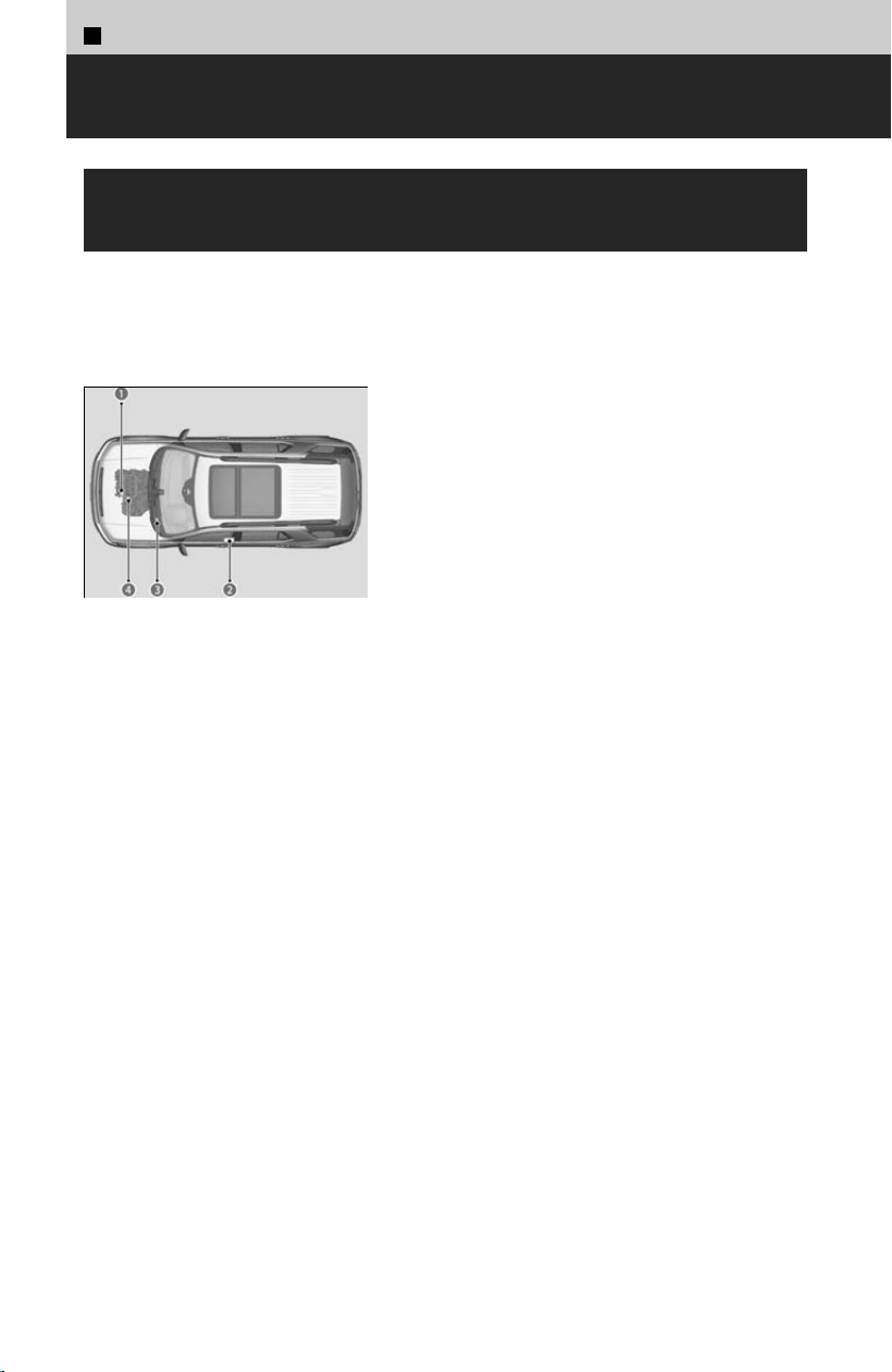
8
Vehicle Information >
Identification Numbers
Vehicle Identification Number (VIN), Engine
Number and Transmission Number
Your vehicle has a 17-digit vehicle identification number (
VIN) used to register your
vehicle for warranty purposes, and for licensing and insuring your vehicle. The
locations of your vehicle’s VIN, engine number and transmission number are shown
as follows.
a Engine Number
b Cer
tification Label/Vehicle Identification
Number
c Vehicle Identification Number
d Automatic Transmission Number
418

8
Vehicle Information >
Devices that Emit Radio Waves
About Devices that Emit Radio Waves
Each radio frequency device installed in the vehicle conforms to the requirements and
s
tandards of the regulation listed below:
As required by the FCC:
This device complies with Part 15 of the FCC rules. Operation is
subject t
o the following two conditions: (1) This device may not
cause harmful interference, and (2) this device must accept any
interference received, including interference that may cause
undesired operation.
Changes or modifications not e
xpressly approved by the party
responsible for compliance could void the user’s authority to
operate the equipment.
This device complies with Industry Canada licence-exempt RSS standard(s).
Oper
ation is subject to the following two conditions: (1) this device may not cause
interference, and (2) this device must accept any interference, including interference
that may cause undesired operation of the device.
419
8
Vehicle Information

8
Vehicle Information >
Reporting Safety Defects
About Reporting
In the U.S.
If you believe that your vehicle has a defect which could cause a
cr
ash or could cause injury or death, you should immediately
inform the National Highway Traffic Safety Administration
(NHTSA) in addition to notifying American Honda Motor Co., Inc.
If NHTSA receives similar complaints, it may open an
investigation, and if it finds that a safety defect exists in a group
of vehicles, it may order a recall and remedy campaign.
However, NHTSA cannot become involved in individual
problems between you, your dealer, or American Honda Motor
Co., Inc.
To contact NHTSA, you may call the Vehicle Safety Hotline toll-
free at 1-888-327-4236 (TTY: 1-877-561-7439); go to http://
www.safercar.gov; or write to: Administrator, NHTSA, 1200 New
Jersey Avenue, SE., Washington, DC 20590. You can also obtain
other information about motor vehicle safety from http://
www.safercar.gov.
In Canada
If you believe that your vehicle has a defect which could cause a
cr
ash or could cause injury or death, you should immediately
inform Honda Canada Inc. and you may also inform Transport
Canada.
If Transport Canada receives similar complaints, it may open an
investigation, and if it finds that a safety defect exists in a group
of vehicles, it may lead to a recall and remedy campaign.
However, Transport Canada cannot become involved in
individual problems between you, your dealer, or Honda Canada
Inc.
420


8
Vehicle Information >
Emissions Testing
Testing of Readiness Codes
Your vehicle has readiness code as part of the onboard self diagnostic system.
Some states use these codes for testing to verify whether your vehicle’s emissions
c
omponents are working properly.
The codes may not be read properly if testing is performed just after the battery has
gone dead or been disconnected.
To check the state of the readiness codes, set the power mode to ON, without starting
the engine. The malfunction indicator lamp will come on for 15 to 20 seconds. If the
malfunction indicator lamp then turns off, the readiness codes are set. If the
malfunction indicator lamp blinks five to ten times, the readiness codes are not set.
If you are required to have your vehicle tested and the readiness codes are not set,
prepare the vehicle for testing by doing the following:
[1] Fill the gas tank to approximately 3/4 full.
[
2] Drive the vehicle for about 10 minutes, reaching 50 to 70 mph (80 to 112 km/h)
at least once during this drive, and make sure transmission is shifting throughout
10 available gears.
( If you want to make sure the top gear shifted properly, you can check the
sequential mode gear selection indicator by using the + paddle shifter.)
[3] Park the vehicle and leave the engine off for 6 hours or more.
[4] Make sure the ambient temperature is between 40°F and 95°F (4°C and 35°C).
[5] Start the engine without touching the accelerator pedal, and let it idle for 20
seconds.
[6] Keep the vehicle in P . Increase the engine speed to 2,000 rpm, and hold it
there for about 3 minutes.
[7] Let the engine idle with your foot off the accelerator for 20 seconds.
[8] Select a nearby, lightly traveled major highway where you can maintain a speed
of 50 to 60 mph (80 to 97 km/h) for at least 20 minutes. Drive on the highway in
D . Do not use cruise control. When traffic allows, drive for 90 seconds without
moving the accelerator pedal. (Vehicle speed may vary slightly; this is okay.) If
you cannot do this for a continuous 90 seconds because of traffic conditions,
drive for at least 30 seconds, then repeat it two more times (for a total of 90
seconds).
[9] Drive in city or suburban traffic for at least 10 minutes. When traffic conditions
allow, let the vehicle coast for several seconds without using the accelerator
pedal or the brake pedal.
[
10
] Park the vehicle and leave the engine off for 30 minutes.
[
11
] If this procedure is done immediately after losing 12-volt battery power, several
additional hours of driving may be required to set all codes.
422

If a testing facility determines that the readiness codes are not set, you may be
requested to return at a later date to complete the test.
If the testing facility determines the readiness codes are still not set, see a dealer.
8
Vehicle Information > Emissions Testing
423
8
Vehicle Information

8
Vehicle Information >
Warranty Coverages
About Warranty Coverages
U.S. Owners
Your new vehicle is covered by these warranties:
New Vehicle Limited Warranty – c
overs your new vehicle, except for the
emissions control systems and accessories, against defects in materials and
workmanship.
Emissions Control Systems Defects Warranty and Emissions Performance
Warranty – these two warranties cover your vehicle’s emissions control systems.
Time, mileage, and coverage are conditional. Please read your warranty booklet for
exact information.
Seat Belt Limited Warranty – a seat belt that fails to function properly is covered
by a limited warranty. Please read your warranty booklet for details.
Rust Perforation Limited Warranty – all exterior body panels are covered against
rusting from the inside out for the specified time period, regardless of mileage.
Accessory Limited Warranty – Honda accessories are covered under this
warranty. Time and mileage limits depend on the type of accessory and other
factors. Please read your warranty booklet for details.
Replacement Parts Limited Warranty – covers all Honda replacement parts
against defects in materials and workmanship.
Replacement 12-Volt Battery Limited Warranty – provides prorated coverage for
a replacement battery purchased from your dealer.
Replacement Muffler Lifetime Limited Warranty – provides coverage for as long
as the purchaser of the muffler owns the vehicle.
Restrictions and exclusions apply to all these warranties. Please read the Honda
warranty information booklet that came with your vehicle for precise information on
warranty coverages. Your vehicle’s original tires are covered by their manufacturer.
Tire warranty information is in a separate booklet.
424

Statement on Warranty Coverage for Aftermarket and Recycled Parts
The Magnuson-Moss Warranty Act, 15 U.S.C. s.2301 et seq., makes it illegal for
mot
or vehicle manufacturers to void a motor vehicle warranty or deny warranty
coverage solely because an aftermarket or recycled part has been used to repair
the vehicle or someone other than the authorized service provider performed
service on the vehicle.
This provision does not apply to a new motor vehicle purchased solely for
commercial or industrial use.
Under federal law, a manufacturer may deny warranty coverage and charge for
repairs to a vehicle if it is discovered that an aftermarket or recycled part installed
on the vehicle is defective or was installed incorrectly and caused damage to
another part of the vehicle otherwise covered under warranty.
The Federal Trade Commission requires that a manufacturer demonstrate that an
aftermarket or recycled part or service performed by a person other than an
authorized service provider caused damage to another part of the vehicle otherwise
covered under warranty before denying warranty coverage.
Additionally, federal law allows a manufacturer to void a motor vehicle warranty or
deny warranty coverage if the manufacturer provides the article or service to
consumers free of charge under the warranty or the manufacturer has secured a
waiver from the Federal Trade Commission.
Canadian Owners
Please refer to the warranty manual that came with your vehicle.
EPA Contact Information
An owner may obtain further information concerning emission warranties or report
violations o
f the terms of the emission warranties by contacting:
Director,
Light-Duty Vehicle Center,
U.S. Environmental Protection Agency,
Attention: Warranty Claim
2000 Traverwood Drive,
Ann Arbor, MI 48105;
8
Vehicle Information > Warranty Coverages
425
8
Vehicle Information

8
Vehicle Information >
Authorized Manuals
If necessary
Service Express
For electronic copies of service publications, you can purchase a subscription to
Ser
vice Express. Visit https://techinfo.honda.com for pricing and options.
For U.S. Owners
Manuals can be purchased from Helm Incorporated. You can order a manual by
phone at 1 (800) 782-4356 (cr
edit card orders only), or online at
www.helminc.com.
For Canadian Owners
Please contact a dealer to order any manuals that you may require.
426

8
Vehicle Information >
Customer Service Information
Contacts
Honda dealership personnel are trained professionals able to deal with any problems
y
ou may encounter with your vehicle. If, however, you are faced with a problem that
they cannot resolve to your satisfaction, contact Honda Customer Service.
U.S. Owners
American Honda Motor Co., Inc.
Honda Automobile Customer Service
Mail Stop CHI-5
1919 Torrance Blvd.
Torrance, CA 90501-2746
Tel: 1 (800) 999-1009
Canadian Owners
Honda Canada Inc.
Customer Relations 180 Honda Boulevard
Markham, ON
L6C 0H9
Tel: 1-888-9-HONDA-9
Fax: 1-877-939-0909
E-mail: Honda_[email protected]
In Puerto Rico and the U.S. Virgin Islands
Bella International
P.O. Box 190816
San Juan, PR 00919-0816
Tel: 1 (787) 620-7546
In Guam
Triple J Autogroup
157 S. Marine Corps Drive
Tamuning, GU 96913
Tel: (671) 648-2277
In Saipan, Commonwealth of the Northern Mariana Islands
Joeten Motor Company, Inc.
P.O. Box 500680
Saipan, MP 96950
Tel: (670) 234-5562
When you call or write, please give us the following information:
427
8
Vehicle Information

Vehicle Identification Number
Vehicle Identification Number (VIN), Engine Number and Transmission Number
u
P.418
Date of purchase
Odometer reading of your vehicle
Your name, address, and telephone number
A detailed description of the problem
Name of the dealer who sold the vehicle to you
8
Vehicle Information > Customer Service Information
428

8
Vehicle Information >
Open Source License
Summary
Meter Open Source License
The software embedded in this product includes open source software. Refer to the
f
ollowing website for details regarding the open source software.
https://www.denso.com/global/en/opensource/meter/honda/
TCU Open Source License
To obtain the source code under GPL, LGPL, MPL, and other open source licenses
that hav
e the obligations to disclose source code, that is contained in this product,
and to access all referred license terms, copyright notices and other relevant
documents please visit https://opensource.lge.com. LG Electronics will also provide
open source code to you on CD-ROM for a charge covering the cost of performing
such distribution (such as the cost of media, shipping, and handling) upon email
request to opensource@lge.com. This offer is valid to anyone in receipt of this
information for a period of three years after our last shipment of this product.
Front Sensor Camera Open Source License
“The product includes code under public domain:
https://www.jonolick.com/uploads/7/9/2/1/7921194/jo_jpeg.cpp
The code is based on
https://github.com/jpeg-js/jpeg-js/blob/master/lib/encoder.js
Copyright (c) 2008, Adobe Systems Incorporated
All rights reserved.
Redistribution and use in source and binary forms, with or without modification, ar
e
permitted provided that the following conditions are met:
* Redistributions of source code must retain the above copyright notice, this list of
conditions and the following disclaimer.
* Redistributions in binary form must reproduce the above copyright notice, this list
of conditions and the following disclaimer in the documentation and/or other
materials provided with the distribution.
* Neither the name of Adobe Systems Incorporated nor the names of its
contributors may be used to endorse or promote products derived from this
software without specific prior written permission.
429
8
Vehicle Information

THIS SOFTWARE IS PROVIDED BY THE COPYRIGHT HOLDERS AND
CONTRIBUTORS "AS IS" AND ANY EXPRESS OR IMPLIED WARRANTIES,
INCLUDING, BUT NOT LIMITED TO, THE IMPLIED WARRANTIES OF
MERCHANTABILITY AND FITNESS FOR A PARTICULAR PURPOSE ARE
DISCLAIMED. IN NO EVENT SHALL THE COPYRIGHT OWNER OR CONTRIBUTORS
BE LIABLE FOR ANY DIRECT, INDIRECT, INCIDENTAL, SPECIAL, EXEMPLARY, OR
CONSEQUENTIAL DAMAGES (INCLUDING, BUT NOT LIMITED TO, PROCUREMENT
OF SUBSTITUTE GOODS OR SERVICES; LOSS OF USE, DATA, OR PROFITS; OR
BUSINESS INTERRUPTION) HOWEVER CAUSED AND ON ANY THEORY OF
LIABILITY, WHETHER IN CONTRACT, STRICT LIABILITY, OR TORT (INCLUDING
NEGLIGENCE OR OTHERWISE) ARISING IN ANY WAY OUT OF THE USE OF THIS
SOFTWARE, EVEN IF ADVISED OF THE POSSIBILITY OF SUCH DAMAGE.
*/
/*
8
Vehicle Information > Open Source License
430

Numbers
12.3″ Color Touchscreen・・・・・・・・・・・・・・・・・・・・・・ 208
12-
Volt Battery・・・・・・・・・・・・・・・・・・・・・・・・・・・・・・・・ 376
Charging System Indicator・・・・・・・・・・・・・・・・・・ 326
If the 12-volt Battery Is Dead・・・・・・・・・・・・・・・ 397
Maintenance (Checking the 12-Volt Battery)・・・・・
・・・・・・・・・・・・・・・・・・・・・・・・・・・・・・・・・・・・・・・・・・・・ 377
A
ABS (Anti-lock Brake System)・・・・・・・・・・・・・・・・・ 126
Ac
cessories・・・・・・・・・・・・・・・・・・・・・・・・・・・・・・・・・・・・・ 31
Accessory Power Sockets・・・・・・・・・・・・・・・・・・・・・ 176
AC Power Outlet・・・・・・・・・・・・・・・・・・・・・・・・・・・・・・・ 177
Adaptive Cruise Control (ACC) with Low Speed
Follow・・・・・・・・・・・・・・・・・・・・・・・・・・・・・・・・・・・・・・・・289
Additives
Engine Coolant・・・・・・・・・・・・・・・・・・・・・・・・・・・・・・ 358
Engine Oil・・・・・・・・・・・・・・・・・・・・・・・・・・・・・・・・・・・ 355
Window Washer Fluid・・・・・・・・・・・・・・・・・・・・・・・ 361
Agile Handling Assist・・・・・・・・・・・・・・・・・・・・・・・・・・ 168
Air Conditioning System (Climate Control System)
・・・・・・・・・・・・・・・・・・・・・・・・・・・・・・・・・・・・・・・・・・・・・・・ 194
Air Pressure・・・・・・・・・・・・・・・・・・・・・・・・・・・・・・ 367, 417
Airbags・・・・・・・・・・・・・・・・・・・・・・・・・・・・・・・・・・・・・・・・・・32
Advanced Airbags・・・・・・・・・・・・・・・・・・・・・・・・・・・・ 36
After a Collision・・・・・・・・・・・・・・・・・・・・・・・・・・・・・・・32
Airbag Care・・・・・・・・・・・・・・・・・・・・・・・・・・・・・・・・・・・ 44
Event Data Recorders・・・・・・・・・・・・・・・・・・・・・・・・・・ 4
Front Airbags (SRS)・・・・・・・・・・・・・・・・・・・・・・・・・・・34
Indicator・・・・・・・・・・・・・・・・・・・・・・・・・・・・・・・・ 42, 326
Knee Airbags・・・・・・・・・・・・・・・・・・・・・・・・・・・・・・・・・ 38
Passenger Airbag Off Indicator・・・・・・・・・・・・・・・ 43
Sensors・・・・・・・・・・・・・・・・・・・・・・・・・・・・・・・・・・・・・・・33
Side Airbags・・・・・・・・・・・・・・・・・・・・・・・・・・・・・・・・・・ 40
Side Curtain Airbags・・・・・・・・・・・・・・・・・・・・・・・・・・ 41
Ambient Meter・・・・・・・・・・・・・・・・・・・・・・・・・・・・・・・・・331
AM/FM Radio・・・・・・・・・・・・・・・・・・・・・・・・・・・・・・・・・・ 215
Android Auto™・・・・・・・・・・・・・・・・・・・・・・・・・・・・・・・・・ 228
Anti-lock Brake System (ABS)・・・・・・・・・・・・・・・・・ 126
Indicator・・・・・・・・・・・・・・・・・・・・・・・・・・・・・・・・・・・・ 327
Apple CarPlay・・・・・・・・・・・・・・・・・・・・・・・・・・・・・・・・・ 225
Armrest
Front Seat・・・・・・・・・・・・・・・・・・・・・・・・・・・・・・・・・・・・ 67
Rear Seat・・・・・・・・・・・・・・・・・・・・・・・・・・・・・・・・・・・・・ 69
AT&T Hotspot・・・・・・・・・・・・・・・・・・・・・・・・・・・・・・・・・・ 224
Audio Playback via Bluetooth® Device・・・・・・・・・ 220
Audio Remote Controls・・・・・・・・・・・・・・・・・・・・・・・・ 203
Audio System・・・・・・・・・・・・・・・・・・・・・・・・・・・・・・・・・・208
12.3″ Color T
ouchscreen・・・・・・・・・・・・・・・・・・・・ 208
About Audio Playback・・・・・・・・・・・・・・・・・・・・・・・ 217
Adjusting the Sound・・・・・・・・・・・・・・・・・・・・・・・・・213
Alexa Built-In・・・・・・・・・・・・・・・・・・・・・・・・・・・・・・・ 214
AM/FM Radio・・・・・・・・・・・・・・・・・・・・・・・・・・・・・・・・215
Android Auto™・・・・・・・・・・・・・・・・・・・・・・・・・・・・・・ 228
Apple CarPlay・・・・・・・・・・・・・・・・・・・・・・・・・・・・・・・ 225
AT&T Hotspot・・・・・・・・・・・・・・・・・・・・・・・・・・・・・・・ 224
Audio/Information Screen・・・・・・・・・・・・・・・・・・・ 199
Bluetooth® Audio・・・・・・・・・・・・・・・・・・・・・・・・・・・・ 220
Display Setup・・・・・・・・・・・・・・・・・・・・・・・・・・・・・・・ 214
General Information・・・・・・・・・・・・・・・・・・・・・・・・・249
Google built-in・・・・・・・・・・・・・・・・・・・・・・・・・・・・・・ 230
Home Screen・・・・・・・・・・・・・・・・・・・・・・・・・・・・・・・・209
How to Update Wirelessly・・・・・・・・・・・・・・・・・・・ 210
Reactivating・・・・・・・・・・・・・・・・・・・・・・・・・・・・・・・・・ 199
Remote Controls・・・・・・・・・・・・・・・・・・・・・・・・・・・・ 203
Selecting an Audio Source・・・・・・・・・・・・・・・・・・・200
Status Bar・・・・・・・・・・・・・・・・・・・・・・・・・・・・・・・・・・・ 201
System Updates・・・・・・・・・・・・・・・・・・・・・・・・・・・・・210
Theft Protection・・・・・・・・・・・・・・・・・・・・・・・・・・・・・ 199
USB Flash Drives・・・・・・・・・・・・・・・・・・・・・・・219, 249
USB Ports・・・・・・・・・・・・・・・・・・・・・・・・・・・・・・・・・・・ 202
Wired Connection・・・・・・・・・・・・・・・・・・・・・・・・・・・ 218
Audio/Information Screen・・・・・・・・・・・・・・・・・・・・・ 199
Authorized Manuals・・・・・・・・・・・・・・・・・・・・・・・・・・・ 426
Auto Door Locking/Unlocking・・・・・・・・・・・・・・・・・・・ 60
Auto High-Beam・・・・・・・・・・・・・・・・・・・・・・・・・・・・・・・ 148
Indicator・・・・・・・・・・・・・・・・・・・・・・・・・・・・・・・・・・・・ 149
Auto Idle Stop・・・・・・・・・・・・・・・・・・・・・・・・・・・・・・・・・ 161
OFF Button・・・・・・・・・・・・・・・・・・・・・・・・・・・・・・・・・・162
Automatic Brake Hold・・・・・・・・・・・・・・・・・・・・・・・・・ 123
Indicator・・・・・・・・・・・・・・・・・・・・・・・・・・・・・・・・・・・・ 125
Automatic Brake Hold System・・・・・・・・・・・・・・・・・123
Indicator・・・・・・・・・・・・・・・・・・・・・・・・・・・・・・・・・・・・ 124
Automatic Climate Control Sensors・・・・・・・・・・・ 196
Automatic Climate Control System・・・・・・・・・・・・ 194
Automatic Dimming Rearview Mirror・・・・・・・・・・・・80
Automatic Folding Door Mirror・・・・・・・・・・・・・・・・・・ 81
Automatic Intermittent Wipers・・・・・・・・・・・153, 154
AUTO Sensitivity Adjustment・・・・・・・・・・・・・・・・ 153
Rainfall Sensor・・・・・・・・・・・・・・・・・・・・・・・・・・・・・・ 154
Automatic Lighting Off Feature・・・・・・・・・・・・・・・・ 147
Automatic Power Off・・・・・・・・・・・・・・・・・・・・・・・・・・ 110
Automatic Transmission・・・・・・・・・・・・・・・・・・・・・・・ 128
Creeping・・・・・・・・・・・・・・・・・・・・・・・・・・・・・・・・・・・・ 128
Fluid・・・・・・・・・・・・・・・・・・・・・・・・・・・・・・・・・・・・・・・・ 360
Index
431
Index

Kickdown・・・・・・・・・・・・・・・・・・・・・・・・・・・・・・・・・・・・128
Operating the Shift Button・・・・・・・・・・・・・・・・・・・115
Shifting・・・・・・・・・・・・・・・・・・・・・・・・・・・・・・・・・・・・・・115
Average Fuel Economy・・・・・・・・・・・・・・・・・・・・・・・・ 335
Average Speed・・・・・・・・・・・・・・・・・・・・・・・・・・・・・・・・ 335
AWD Torque Distribution Monitor・・・・・・・・・・・・・・338
B
Belts (Seat)・・・・・・・・・・・・・・・・・・・・・・・・・・・・・・・・・・・・・ 73
Be
verage Holders・・・・・・・・・・・・・・・・・・・・・・・・・・・・・・183
Blind Spot Information System・・・・・・・・・・・・・・・・ 311
Bluetooth® Audio・・・・・・・・・・・・・・・・・・・・・・・・・・・・・・ 220
Bluetooth® HandsFreeLink®・・・・・・・・・・・・・・・・・・・・234
Booster Seats (For Children)・・・・・・・・・・・・・・・・・・・・ 29
Brake System
Indicator (Amber)・・・・・・・・・・・・・・・・・・・・・・・・・・・ 325
Indicator (Red)・・・・・・・・・・・・・・・・・・・・・・・・・・・・・・ 325
Braking・・・・・・・・・・・・・・・・・・・・・・・・・・・・・・・・・・・・・・・・ 120
Anti-lock Brake System (ABS)・・・・・・・・・・・・・・・ 126
Automatic Brake Hold・・・・・・・・・・・・・・・・・・・・・・・ 123
Brake Assist System・・・・・・・・・・・・・・・・・・・・・・・・・120
Fluid・・・・・・・・・・・・・・・・・・・・・・・・・・・・・・・・・・・・・・・・ 361
Foot Brake・・・・・・・・・・・・・・・・・・・・・・・・・・・・・・・・・・ 120
Parking Brake・・・・・・・・・・・・・・・・・・・・・・・・・・・・・・・ 121
Brightness Setting・・・・・・・・・・・・・・・・・・・・・・・・・・・・・ 340
Built-in Key・・・・・・・・・・・・・・・・・・・・・・・・・・・・・・・・・・・・・ 50
Bulb Replacement・・・・・・・・・・・・・・・・・・・・・・・・・・・・・ 385
Back-Up Lights・・・・・・・・・・・・・・・・・・・・・・・・・・・・・・ 385
Brake Lights・・・・・・・・・・・・・・・・・・・・・・・・・・・・・・・・・385
Fog Lights・・・・・・・・・・・・・・・・・・・・・・・・・・・・・・・・・・・ 385
Front Side Marker Lights・・・・・・・・・・・・・・・・・・・・ 385
Front Turn Signal Lights・・・・・・・・・・・・・・・・・・・・・ 385
Headlights・・・・・・・・・・・・・・・・・・・・・・・・・・・・・・・・・・ 385
High-Mount Brake Light・・・・・・・・・・・・・・・・・・・・・ 385
Parking/Daytime Running Lights・・・・・・・・・・・・ 385
Puddle Lights・・・・・・・・・・・・・・・・・・・・・・・・・・・・・・・ 385
Rear License Plate Light・・・・・・・・・・・・・・・・・・・・・385
Rear Side Marker Lights・・・・・・・・・・・・・・・・・・・・・ 385
Rear Turn Signal Lights・・・・・・・・・・・・・・・・・・・・・・ 385
Side Turn Signal/Emergency Indicator Lights・・・・
・・・・・・・・・・・・・・・・・・・・・・・・・・・・・・・・・・・・・・・・・・・・ 385
Taillights・・・・・・・・・・・・・・・・・・・・・・・・・・・・・・・・・・・・ 385
Vanity Mirror Lights・・・・・・・・・・・・・・・・・・・・・・・・・・386
Bulb Specifications・・・・・・・・・・・・・・・・・・・・・・・・・・・・ 416
C
Car Wash Mode・・・・・・・・・・・・・・・・・・・・・・・・・・・・・・・・ 117
Carbon Mono
xide Gas・・・・・・・・・・・・・・・・・・・・・・・・・・・30
Cargo Area Light・・・・・・・・・・・・・・・・・・・・・・・・・・・・・・・ 175
Car
go Hook・・・・・・・・・・・・・・・・・・・・・・・・・・・・・・・・・・・・ 181
CAMERA Button・・・・・・・・・・・・・・・・・・・・・・・・・・・・・・・ 133
Center Console Box・・・・・・・・・・・・・・・・・・・・・・・・・・・・176
Certification Label・・・・・・・・・・・・・・・・・・・・・・・・・・・・・ 418
Changing Bulbs・・・・・・・・・・・・・・・・・・・・・・・・・・・・・・・・ 385
Charging System Indicator・・・・・・・・・・・・・・・・・・・・ 326
Check Before Driving・・・・・・・・・・・・・・・・・・・・・・・・・・・・14
Child Safety・・・・・・・・・・・・・・・・・・・・・・・・・・・・・・・・・・・・・ 19
Child Seat・・・・・・・・・・・・・・・・・・・・・・・・・・・・・・・・・・・・・・・ 19
Booster Seats・・・・・・・・・・・・・・・・・・・・・・・・・・・・・・・・・29
Child Seat for Infants・・・・・・・・・・・・・・・・・・・・・・・・・ 20
Child Seat for Small Children・・・・・・・・・・・・・・・・・ 21
Installing・・・・・・・・・・・・・・・・・・・・・・・・・・・・・・・・・・・・・ 23
Installing a Child Seat with a Lap/Shoulder Seat
Belt ・・・・・・・・・・・・・・・・・・・・・・・・・・・・・・・・・・・・・・・・・ 25
Larger Children・・・・・・・・・・・・・・・・・・・・・・・・・・・・・・・ 28
Rear-facing Child Seat・・・・・・・・・・・・・・・・・・・・・・・・ 21
Selecting a Child Seat・・・・・・・・・・・・・・・・・・・・・・・・ 22
Childproof Door Locks・・・・・・・・・・・・・・・・・・・・・・・・・・ 61
Cleaning the Exterior・・・・・・・・・・・・・・・・・・・・・・・・・・ 380
Cleaning the Interior・・・・・・・・・・・・・・・・・・・・・・・・・・・379
Climate Control System・・・・・・・・・・・・・・・・・・・・・・・ 194
Automatic Climate Control Sensors・・・・・・・・・ 196
Automatic Climate Control System・・・・・・・・・・ 194
Fresh Air Mode・・・・・・・・・・・・・・・・・・・・・・・・・・・・・・ 194
Rear Climate Control System・・・・・・・・・・・・・・・・ 197
Recirculation Mode・・・・・・・・・・・・・・・・・・・・・・・・・・194
Synchronization Mode・・・・・・・・・・・・・・・・・・・・・・・ 195
Using Automatic Climate Control・・・・・・・・・・・・ 195
Clock・・・・・・・・・・・・・・・・・・・・・・・・・・・・・・・・・・・・・ 212, 341
CMBS™ (Collision Mitigation Braking System™)・・・・
・・・・・・・・・・・・・・・・・・・・・・・・・・・・・・・・・・・・・・・・・・・・・・・ 274
Coat Hook・・・・・・・・・・・・・・・・・・・・・・・・・・・・・・・・・・・・・ 181
Collision Mitigation Braking System™(CMBS™)・・・・・
・・・・・・・・・・・・・・・・・・・・・・・・・・・・・・・・・・・・・・・・・・・・・・・ 274
Compact Spare Tire・・・・・・・・・・・・・・・・・・・・・・ 389, 417
Console Compartment・・・・・・・・・・・・・・・・・・・・・・・・・176
Coolant (Engine)・・・・・・・・・・・・・・・・・・・・・・・・・・・・・・・ 358
Adding to the Radiator・・・・・・・・・・・・・・・・・・・・・・ 360
Adding to the Reserve Tank・・・・・・・・・・・・・・・・・ 359
Overheating・・・・・・・・・・・・・・・・・・・・・・・・・・・・・・・・・ 399
Creeping・・・・・・・・・・・・・・・・・・・・・・・・・・・・・・・・・・・・・・・ 128
Cross Traffic Monitor・・・・・・・・・・・・・・・・・・・・・・・・・・ 314
Cup Holders・・・・・・・・・・・・・・・・・・・・・・・・・・・・・・・・・・・ 183
Current Mode for Adaptive Cruise Control (ACC)
with Low Speed Follow, the Lane Keeping Assist
System (LKAS), and Traffic Jam Assist・・・・・・・ 332
Index
432

Customer Service Information・・・・・・・・・・・・・・・・・427
Customize Display・・・・・・・・・・・・・・・・・・・・・・・・・・・・・ 342
Customized Features・・・・・・・・・・・・・・・・・・・・・・・・・・ 239
D
Daytime Running Lights・・・・・・・・・・・・・・・・・・・・・・・ 148
Dead Bat
tery・・・・・・・・・・・・・・・・・・・・・・・・・・・・・・・・・・ 397
Defaulting All the Settings・・・・・・・・・・・・・・・・・・・・・ 248
Defroster・・・・・・・・・・・・・・・・・・・・・・・・・・・・・・・・・・・・・・ 156
Heated Door Mirror・・・・・・・・・・・・・・・・・・・・・・・・・・156
Rear Defogger・・・・・・・・・・・・・・・・・・・・・・・・・・・・・・・156
Defrosting the Windshield and Windows・・・・・・ 156
Devices that Emit Radio Waves・・・・・・・・・・・・・・・・ 419
Dipstick (Engine Oil)・・・・・・・・・・・・・・・・・・・・・・・・・・・ 355
Display Setup・・・・・・・・・・・・・・・・・・・・・・・・・・・・・・・・・・214
Door Mirrors・・・・・・・・・・・・・・・・・・・・・・・・・・・・・・・・・・・・ 80
DOT Tire Quality Grading・・・・・・・・・・・・・・・・・・・・・・ 370
Drive Lock Mode・・・・・・・・・・・・・・・・・・・・・・・・・・・・・・・・ 60
Drive Mode System・・・・・・・・・・・・・・・・・・・・・・・・・・・・ 159
Driver Attention Monitor・・・・・・・・・・・・・・・・・・・・・・・ 336
Driver Information Interface・・・・・・・・・・・・・ 334, 341
Switching the Display・・・・・・・・・・・・・・・・・・・・・・・ 334
Driver’s Door Open Mode・・・・・・・・・・・・・・・・・・・・・・・ 60
Driving Features・・・・・・・・・・・・・・・・・・・・・・・・・・・・・・・ 159
Agile Handling Assist・・・・・・・・・・・・・・・・・・・・・・・・ 168
Auto Idle Stop・・・・・・・・・・・・・・・・・・・・・・・・・・・・・・・161
Drive Mode System・・・・・・・・・・・・・・・・・・・・・・・・・・159
Hill Descent Control System・・・・・・・・・・・・・・・・・164
Intelligent Variable Torque Management (i-
VTM4™) AWD System・・・・・・・・・・・・・・・・・・・・・・ 168
Tire Pressure Monitoring System (TPMS) with
Tire Fill Assist・・・・・・・・・・・・・・・・・・・・・・・・・・・・・・169
Vehicle Stability Assist™ (VSA®), aka Electronic
Stability Control (ESC), System・・・・・・・・・・・・ 166
Driving Position Memory System・・・・・・・・・・・・・・・・70
Driving Preparation・・・・・・・・・・・・・・・・・・・・・・・・・・・・・ 17
E
Elapsed Time・・・・・・・・・・・・・・・・・・・・・・・・・・・・・・・・・・ 335
Electric P
ower Steering (EPS) System
Indicator・・・・・・・・・・・・・・・・・・・・・・・・・・・・・・・・・・・・ 327
Electronic Stability Control (ESC)・・・・・・・・・・・・・・ 166
Elevation and Compass・・・・・・・・・・・・・・・・・・・・・・・・342
Emergency Call (eCall)・・・・・・・・・・・・・・・・・・・・・・・・・413
Automatic Emergency Call・・・・・・・・・・・・・・・・・・ 413
Manual Emergency Call・・・・・・・・・・・・・・・・・・・・・ 414
Emergency Towing・・・・・・・・・・・・・・・・・・・・・・・・・・・・・409
Emissions Testing (Readiness Codes)・・・・・・・・・ 422
Engine
Coolant・・・・・・・・・・・・・・・・・・・・・・・・・・・・・・・・・・・・・・358
If the 12-
volt Battery Is Dead・・・・・・・・・・・・・・・ 397
Number・・・・・・・・・・・・・・・・・・・・・・・・・・・・・・・・・・・・・ 418
Oil・・・・・・・・・・・・・・・・・・・・・・・・・・・・・・・・・・・・・・・・・・・354
Remote Engine Start・・・・・・・・・・・・・・・・・・・・・・・・ 112
Starting・・・・・・・・・・・・・・・・・・・・・・・・・・・・・・・・・・・・・ 111
Engine Coolant・・・・・・・・・・・・・・・・・・・・・・・・・・・・・・・・ 358
Adding to the Radiator・・・・・・・・・・・・・・・・・・・・・・ 360
Adding to the Reserve Tank・・・・・・・・・・・・・・・・・ 359
Overheating・・・・・・・・・・・・・・・・・・・・・・・・・・・・・・・・・ 399
Temperature Gauge・・・・・・・・・・・・・・・・・・・・・・・・・ 331
Engine Oil・・・・・・・・・・・・・・・・・・・・・・・・・・・・・・・・・・・・・・354
Adding・・・・・・・・・・・・・・・・・・・・・・・・・・・・・・・・・・・・・・ 356
Checking・・・・・・・・・・・・・・・・・・・・・・・・・・・・・・・・・・・・ 355
Displaying Oil Life・・・・・・・・・・・・・・・・・・・・・・・・・・・ 348
Engine oil pressure low Warning・・・・・・・・・・・・ 401
Recommended Engine Oil・・・・・・・・・・・・・・・・・・・354
ENGINE START/STOP Button・・・・・・・・・・・・・・・・・・ 110
Automatic Power Off・・・・・・・・・・・・・・・・・・・・・・・・ 110
Power Mode Reminder・・・・・・・・・・・・・・・・・・・・・・ 110
Exhaust Gas Hazard (Carbon Monoxide)・・・・・・・・ 30
Exterior Care (Cleaning)・・・・・・・・・・・・・・・・・・・・・・・ 380
Exterior Mirrors・・・・・・・・・・・・・・・・・・・・・・・・・・・・・・・・・ 80
F
Filters
Oil・・・・・・・・・・・・・・・・・・・・・・・・・・・・・・・・・・・・・・・・・・・357
Flat Tir
e・・・・・・・・・・・・・・・・・・・・・・・・・・・・・・・・・・・・・・・ 389
Floor Mats・・・・・・・・・・・・・・・・・・・・・・・・・・・・・・・・・・・・・ 380
Fluids
Automatic Transmission・・・・・・・・・・・・・・・・・・・・・360
Brake・・・・・・・・・・・・・・・・・・・・・・・・・・・・・・・・・・・・・・・・361
Engine Coolant・・・・・・・・・・・・・・・・・・・・・・・・・・・・・・ 358
Windshield Washer・・・・・・・・・・・・・・・・・・・・・・・・・・361
FM/AM Radio・・・・・・・・・・・・・・・・・・・・・・・・・・・・・・・・・・ 215
Fog Lights・・・・・・・・・・・・・・・・・・・・・・・・・・・・・・・・・・・・・ 148
Indicator・・・・・・・・・・・・・・・・・・・・・・・・・・・・・・・・・・・・ 148
Folding Down the Rear Seats・・・・・・・・・・・・・・・・・・・ 69
Foot Brake・・・・・・・・・・・・・・・・・・・・・・・・・・・・・・・・・・・・・ 120
Fresh Air Mode・・・・・・・・・・・・・・・・・・・・・・・・・・・・・・・・ 194
Front Airbags (SRS)・・・・・・・・・・・・・・・・・・・・・・・・・・・・・ 34
Front Seat Heaters・・・・・・・・・・・・・・・・・・・・・・・・・・・・ 188
Front Seats・・・・・・・・・・・・・・・・・・・・・・・・・・・・・・・・・・・・・・66
Lumbar Support Adjustment Switch・・・・・・・・・・ 67
Front Sensor Camera・・・・・・・・・・・・・・・・・・・・・・・・・・ 270
Fuel・・・・・・・・・・・・・・・・・・・・・・・・・・・・・・・・・・・・・・・・・・・・141
Average Fuel Economy・・・・・・・・・・・・・・・・・・・・・・ 335
Index
433
Index

Gauge・・・・・・・・・・・・・・・・・・・・・・・・・・・・・・・・・・・・・・・ 331
Instant Fuel Economy・・・・・・・・・・・・・・・・・・・・・・・ 335
Low Fuel Indicator・・・・・・・・・・・・・・・・・・・・・・・・・・ 327
Range・・・・・・・・・・・・・・・・・・・・・・・・・・・・・・・・・・・・・・・ 334
Recommendation・・・・・・・・・・・・・・・・・・・・・・・・・・・ 141
Refueling・・・・・・・・・・・・・・・・・・・・・・・・・・・・・・・・・・・・ 142
Fuel Economy・・・・・・・・・・・・・・・・・・・・・・・・・・・・・・・・・ 144
Fuel Fill Door・・・・・・・・・・・・・・・・・・・・・・・・・・・・・・・・・・ 142
Unable to Unlock・・・・・・・・・・・・・・・・・・・・・・・・・・・・ 410
Fuses・・・・・・・・・・・・・・・・・・・・・・・・・・・・・・・・・・・・・・・・・・ 402
Inspecting and Changing・・・・・・・・・・・・・・・・・・・・ 407
Locations・・・・・・・・・・・・・・・・・・・・・・・・・ 402, 404, 406
G
Gasoline・・・・・・・・・・・・・・・・・・・・・・・・・・・・・・・・・・・・・・・ 141
A
verage Fuel Economy・・・・・・・・・・・・・・・・・・・・・・ 335
Gauge・・・・・・・・・・・・・・・・・・・・・・・・・・・・・・・・・・・・・・・ 331
Instant Fuel Economy・・・・・・・・・・・・・・・・・・・・・・・ 335
Low Fuel Indicator・・・・・・・・・・・・・・・・・・・・・・・・・・ 327
Range・・・・・・・・・・・・・・・・・・・・・・・・・・・・・・・・・・・・・・・ 334
Recommendation・・・・・・・・・・・・・・・・・・・・・・・・・・・ 141
Refueling・・・・・・・・・・・・・・・・・・・・・・・・・・・・・・・・・・・・ 142
Gauge Display Settings・・・・・・・・・・・・・・・・・・・・・・・・ 340
Gauges・・・・・・・・・・・・・・・・・・・・・・・・・・・・・・・・・・・・・・・・ 330
Gear Position Indicator・・・・・・・・・・・・・・・・・・・・・・・・ 116
Gear Shift Positions
Automatic Transmission・・・・・・・・・・・・・・・・・・・・・115
Glass (care)・・・・・・・・・・・・・・・・・・・・・・・・・・・・・・ 379, 381
Glove Box・・・・・・・・・・・・・・・・・・・・・・・・・・・・・・・・・・・・・・176
Google built-in・・・・・・・・・・・・・・・・・・・・・・・・・・・・・・・・・230
H
Handling the Unexpected・・・・・・・・・・・・・・・・・・・・・・384
Hands F
ree Access・・・・・・・・・・・・・・・・・・・・・・・・・・・・・・89
HandsFreeLink® (HFL)・・・・・・・・・・・・・・・・・・・・・・・・・ 234
Automatic Import of Cellular Phonebook and
Call History・・・・・・・・・・・・・・・・・・・・・・・・・・・・・・・・ 239
Automatic Transferring・・・・・・・・・・・・・・・・・・・・・・ 239
Favorite Contacts・・・・・・・・・・・・・・・・・・・・・・・・・・・・235
HFL Buttons・・・・・・・・・・・・・・・・・・・・・・・・・・・・・・・・・203
HFL Menus・・・・・・・・・・・・・・・・・・・・・・・・・・・・・・・・・・ 238
HFL Status Display・・・・・・・・・・・・・・・・・・・・・・・・・・ 235
Making a Call・・・・・・・・・・・・・・・・・・・・・・・・・・・・・・・・236
Options During a Call・・・・・・・・・・・・・・・・・・・・・・・・238
Phone Setup・・・・・・・・・・・・・・・・・・・・・・・・・・・・・・・・ 205
Receiving a Call・・・・・・・・・・・・・・・・・・・・・・・・・・・・・ 237
Ringtone・・・・・・・・・・・・・・・・・・・・・・・・・・・・・・・・・・・・ 239
Hazard Warning Button・・・・・・・・・・・・・・・・・・・・・・・・・ 11
HD Radio™・・・・・・・・・・・・・・・・・・・・・・・・・・・・・・・ 216, 262
Head R
estraints・・・・・・・・・・・・・・・・・・・・・・・・・・・・・・・・・ 65
Adjusting・・・・・・・・・・・・・・・・・・・・・・・・・・・・・・・・・ 66, 68
Headlights
Aiming・・・・・・・・・・・・・・・・・・・・・・・・・・・・・・・・・・・・・・ 385
Auto High-Beam・・・・・・・・・・・・・・・・・・・・・・・・・・・・ 148
Automatic Lighting Off Feature・・・・・・・・・・・・・・ 147
Headlight Integration with Wipers・・・・・・・・・・・147
High Beams・・・・・・・・・・・・・・・・・・・・・・・・・・・・・・・・・ 147
Light Sensor・・・・・・・・・・・・・・・・・・・・・・・・・・・・・・・・・146
Operating・・・・・・・・・・・・・・・・・・・・・・・・・・・・・・・・・・・ 145
Heated Door Mirror・・・・・・・・・・・・・・・・・・・・・・・・・・・・ 156
Heated Steering Wheel・・・・・・・・・・・・・・・・・・・・・・・・ 190
Heated Windshield・・・・・・・・・・・・・・・・・・・・・・・・・・・・ 158
Heaters (Seat)・・・・・・・・・・・・・・・・・・・・・・・・・・・・188, 189
HFL (HandsFreeLink®)・・・・・・・・・・・・・・・・・・・・・・・・・ 234
High Beams・・・・・・・・・・・・・・・・・・・・・・・・・・・・・・・・・・・・147
Indicator・・・・・・・・・・・・・・・・・・・・・・・・・・・・・・・・・・・・ 147
Hill Descent Control System・・・・・・・・・・・・・・・・・・・ 164
Hill Start Assist System・・・・・・・・・・・・・・・・・・・・・・・・127
HomeLink® Universal Transceiver・・・・・・・・・・・・・ 184
Programming a Button・・・・・・・・・・・・・・・・・・・・・・ 185
Training HomeLink® ・・・・・・・・・・・・・・・・・・・・・・・・ 185
Honda App License Agreement・・・・・・・・・・・・・・・・ 250
Honda Sensing®・・・・・・・・・・・・・・・・・・・・・・・・・・・・・・・ 267
HondaLink®・・・・・・・・・・・・・・・・・・・・・・・・・・・・・・・・・・・・ 221
I
iPhone・・・・・・・・・・・・・・・・・・・・・・・・・・・・・・・・・・・・・・・・・ 249
iP
od・・・・・・・・・・・・・・・・・・・・・・・・・・・・・・・・・・・・・・・・・・・・249
Identification Numbers・・・・・・・・・・・・・・・・・・・・・・・・ 418
Engine and Transmission・・・・・・・・・・・・・・・・・・・・ 418
Vehicle Identification・・・・・・・・・・・・・・・・・・・・・・・・418
Immobilizer System・・・・・・・・・・・・・・・・・・・・・・・・・・・・・48
Indicator・・・・・・・・・・・・・・・・・・・・・・・・・・・・・・・・・・・・・・49
Indicator List・・・・・・・・・・・・・・・・・・・・・・・・・・・・・・・・・・ 323
Indicators・・・・・・・・・・・・・・・・・・・・・・・・・・・・・・・・・・・・・ 323
12-Volt Battery Charging System・・・・・・・・・・・・ 326
Adaptive Cruise Control (ACC) with Low Speed
Follow (Amber)・・・・・・・・・・・・・・・・・・・・・・・・・・・・ 328
Adaptive Cruise Control (ACC) with Low Speed
Follow (White/Green)・・・・・・・・・・・・・・・・・・・・・・ 268
Adaptive Cruise Control (ACC) with Low Speed
Follow Indicator・・・・・・・・・・・・・・・・・・・・・・・・・・・ 290
Adaptive Cruise Control (ACC) with Low Speed
Follow Interval・・・・・・・・・・・・・・・・・・・・・・・・・・・・・293
Anti-lock Brake System (ABS)・・・・・・・・・・・・・・・ 327
Auto High-Beam・・・・・・・・・・・・・・・・・・・・・・・・・・・・ 149
Index
434

Auto Idle Stop (Green)・・・・・・・・・・・・・・・・・・・・・・ 161
Auto Idle Stop OFF・・・・・・・・・・・・・・・・・・・・・・・・・・ 162
Auto Idle Stop Suspend・・・・・・・・・・・・・・・・・・・・・ 162
Auto Idle Stop System (Amber)・・・・・・・・・・・・・ 328
Automatic Brake Hold・・・・・・・・・・・・・・・・・・・・・・・ 125
Automatic Brake Hold System・・・・・・・・・・・・・・・124
Cruise Mode (White/Green)・・・・・・・・・・・・・・・・・ 295
ECON Mode・・・・・・・・・・・・・・・・・・・・・・・・・・・・・・・・・ 159
Electric Power Steering (EPS) System・・・・・・・ 327
Fog Light・・・・・・・・・・・・・・・・・・・・・・・・・・・・・・・・・・・・ 148
Gear Position・・・・・・・・・・・・・・・・・・・・・・・・・・・・・・・・116
High Beam・・・・・・・・・・・・・・・・・・・・・・・・・・・・・・・・・・ 147
Hill Descent Control System (White/Green)・・165
Immobilizer System・・・・・・・・・・・・・・・・・・・・・・・・・・ 49
Lane Keeping Assist System (LKAS) (Amber)・・・・・
・・・・・・・・・・・・・・・・・・・・・・・・・・・・・・・・・・・・・・・・・・・・ 328
Lane Keeping Assist System (LKAS) (White/
Green) ・・・・・・・・・・・・・・・・・・・・・・・・・・・・・・・・・・・・・ 268
Lights On・・・・・・・・・・・・・・・・・・・・・・・・・・・・・・・・・・・・ 145
Low Fuel・・・・・・・・・・・・・・・・・・・・・・・・・・・・・・・・・・・・ 327
Low Tire Pressure/TPMS・・・・・・・・・・・・・・・・・・・・ 328
M (sequential mode)/Gear Selection・・・・・・・・ 116
Malfunction Indicator Lamp・・・・・・・・・・・・・・・・・ 326
NORMAL Mode・・・・・・・・・・・・・・・・・・・・・・・・・・・・・・ 159
Parking Brake and Brake System (Amber)・・・ 325
Parking Brake and Brake System (Red)・・・・・・ 325
Safety Support (Amber)・・・・・・・・・・・・・・・・・・・・・ 329
Safety Support (Green/Gray)・・・・・・・・・・・・・・・・ 338
SAND Mode・・・・・・・・・・・・・・・・・・・・・・・・・・・・・・・・・ 159
Seat Belt Reminder・・・・・・・・・・・・・・・・・・・・・ 74, 326
Security System Alarm・・・・・・・・・・・・・・・・・・・・・・・・49
SNOW Mode・・・・・・・・・・・・・・・・・・・・・・・・・・・・・・・・ 159
SPORT Mode・・・・・・・・・・・・・・・・・・・・・・・・・・・・・・・・ 159
Supplemental Restraint System・・・・・・・・・ 43, 326
System Message・・・・・・・・・・・・・・・・・・・・・・・・・・・・ 341
TOW Mode・・・・・・・・・・・・・・・・・・・・・・・・・・・・・・・・・・ 159
Transmission System・・・・・・・・・・・・・・・・・・・・・・・・328
TRAIL Mode・・・・・・・・・・・・・・・・・・・・・・・・・・・・・・・・・ 159
Turn Signal・・・・・・・・・・・・・・・・・・・・・・・・・・・・・・・・・・ 145
Vehicle Stability Assist™ (VSA®) OFF・・・ 167, 327
Vehicle Stability Assist™ (VSA®) System・・・・・・・・・・
・・・・・・・・・・・・・・・・・・・・・・・・・・・・・・・・・・・・・・・ 167, 327
Instant Fuel Economy・・・・・・・・・・・・・・・・・・・・・・・・・ 335
Intelligent VTM4 (i-VTM4™)・・・・・・・・・・・・・・・・・・・ 168
Interior Care (Cleaning)・・・・・・・・・・・・・・・・・・・・・・・・379
Interior Convenience Items・・・・・・・・・・・・・・・・・・・ 176
Interior Lights・・・・・・・・・・・・・・・・・・・・・・・・・・・・・・・・・ 174
Cargo Area Light・・・・・・・・・・・・・・・・・・・・・・・・・・・・ 175
Map Light Switches・・・・・・・・・・・・・・・・・・・・・・・・・・174
Interior Rearview Mirror・・・・・・・・・・・・・・・・・・・・・・・・ 80
Automatic Dimming Rearview Mirror・・・・・・・・・ 80
Intermittent Time Adjustment Ring・・・・・・・・・・・・152
J
Jack (Wheel Nut Wrench)・・・・・・・・・・・・・・・・・・・・・・391
Jump Star
ting・・・・・・・・・・・・・・・・・・・・・・・・・・・・・・・・・ 397
K
Key・・・・・・・・・・・・・・・・・・・・・・・・・・・・・・・・・・・・・・・・・・・・・・47
Buil
t-in Key・・・・・・・・・・・・・・・・・・・・・・・・・・・・・・・・・・・ 50
Key Number Tag・・・・・・・・・・・・・・・・・・・・・・・・・・・・・・ 51
Remote Transmitter・・・・・・・・・・・・・・・・・・・・・・・・・・ 52
Keyless Access System・・・・・・・・・・・・・・・・・・・・・・・・・ 53
Lock Presetting・・・・・・・・・・・・・・・・・・・・・・・・・・・・・・・ 57
Lockout Protection Function・・・・・・・・・・・・・・・・・・ 58
Walk Away Auto Lock®・・・・・・・・・・・・・・・・・・・・・・・・55
Kickdown・・・・・・・・・・・・・・・・・・・・・・・・・・・・・・・・・・・・・・ 128
Knee Airbags・・・・・・・・・・・・・・・・・・・・・・・・・・・・・・・・・・・・38
L
Lane Keeping Assist System (LKAS)・・・・・・・・・・・ 300
L
ATCH (Child Seats)・・・・・・・・・・・・・・・・・・・・・・・・・23, 27
Legal Information on Apple CarPlay/Android Auto
・・・・・・・・・・・・・・・・・・・・・・・・・・・・・・・・・・・・・・・・・・・・・・・ 263
License Information・・・・・・・・・・・・・・・・・・・・・・・・・・・ 260
Light Sensor・・・・・・・・・・・・・・・・・・・・・・・・・・・・・・・・・・・ 146
Lights・・・・・・・・・・・・・・・・・・・・・・・・・・・・・・・・・・・・ 145, 385
Auto High-Beam・・・・・・・・・・・・・・・・・・・・・・・・・・・・ 148
Bulb Replacement・・・・・・・・・・・・・・・・・・・・・・・・・・ 385
Daytime Running Lights・・・・・・・・・・・・・・・・・・・・・ 148
Fog Lights・・・・・・・・・・・・・・・・・・・・・・・・・・・・・・・・・・・ 148
Headlights・・・・・・・・・・・・・・・・・・・・・・・・・・・・・・・・・・ 145
High Beams・・・・・・・・・・・・・・・・・・・・・・・・・・・・・・・・・ 147
Interior Lights・・・・・・・・・・・・・・・・・・・・・・・・・・・・・・・ 174
Light Switches・・・・・・・・・・・・・・・・・・・・・・・・・・・・・・・145
Parking Lights・・・・・・・・・・・・・・・・・・・・・・・・・・・・・・・ 145
Load Limit・・・・・・・・・・・・・・・・・・・・・・・・・・・・・・・・・・・・・・・92
Lock Presetting・・・・・・・・・・・・・・・・・・・・・・・・・・・・・・・・・ 57
Locking the Doors・・・・・・・・・・・・・・・・・・・・・・・52, 54, 57
Locking/Unlocking・・・・・・・・・・・・・・・・・・・・・・・・・・・・・・ 52
Auto Door Locking/Unlocking・・・・・・・・・・・・・・・・・ 60
Childproof Door Locks・・・・・・・・・・・・・・・・・・・・・・・・ 61
From Inside・・・・・・・・・・・・・・・・・・・・・・・・・・・・・・・・・・ 59
From Outside・・・・・・・・・・・・・・・・・・・・・・・・・・・・・ 52, 53
Using a Key・・・・・・・・・・・・・・・・・・・・・・・・・・・・・・・・・・・ 57
Using the Keyless Access System・・・・・・・・・・・・・53
Index
435
Index

Using the Remote Transmitter・・・・・・・・・・・・・・・・ 52
Lockout Protection Function・・・・・・・・・・・・・・・・・・・・ 58
Low Fuel Indicator・・・・・・・・・・・・・・・・・・・・・・・・・・・・・327
Low Speed Braking Control・・・・・・・・・・・・・・・・・・・・ 280
Lower Anchors・・・・・・・・・・・・・・・・・・・・・・・・・・・・・・・・・・ 23
Lubricant Specifications Chart・・・・・・・・・・・・・・・・・ 417
Luggage (Maximum Load Limit)・・・・・・・・・・・・・・・・・ 92
Lumbar Support Adjustment Switch・・・・・・・・・・・・ 67
M
Maintenance・・・・・・・・・・・・・・・・・・・・・・・・・・・・・・・・・・・345
12-
Volt Battery・・・・・・・・・・・・・・・・・・・・・・・・・・・・・・ 376
Brake Fluid・・・・・・・・・・・・・・・・・・・・・・・・・・・・・・・・・・361
Cleaning・・・・・・・・・・・・・・・・・・・・・・・・・・・・・・・・・・・・・379
Coolant・・・・・・・・・・・・・・・・・・・・・・・・・・・・・・・・・・・・・・358
Maintenance Minder™・・・・・・・・・・・・・・・・・・・・・・・ 348
Oil・・・・・・・・・・・・・・・・・・・・・・・・・・・・・・・・・・・・・・・・・・・354
Precautions・・・・・・・・・・・・・・・・・・・・・・・・・・・・・・・・・ 345
Radiator・・・・・・・・・・・・・・・・・・・・・・・・・・・・・・・・・・・・・ 356
Safety・・・・・・・・・・・・・・・・・・・・・・・・・・・・・・・・・・・・・・・ 346
Service Items・・・・・・・・・・・・・・・・・・・・・・・・・・・・・・・ 350
Tires・・・・・・・・・・・・・・・・・・・・・・・・・・・・・・・・・・・・・・・・ 367
Transmission Fluid・・・・・・・・・・・・・・・・・・・・・・・・・・ 360
Under the Hood・・・・・・・・・・・・・・・・・・・・・・・・・・・・・ 353
Malfunction Indicator Lamp・・・・・・・・・・・・・・・・・・・ 326
Manual Intermittent Wipers・・・・・・・・・・・・・・・・・・・ 152
Intermittent Time Adjustment Ring・・・・・・・・・ 152
Map Light Switches・・・・・・・・・・・・・・・・・・・・・・・・・・・・ 174
Master Door Lock Switch・・・・・・・・・・・・・・・・・・・・・・・・60
Maximum Load Limit・・・・・・・・・・・・・・・・・・・・・・・・・・・・ 92
Meters, Gauges・・・・・・・・・・・・・・・・・・・・・・・・・・・・・・・・ 330
Mirrors・・・・・・・・・・・・・・・・・・・・・・・・・・・・・・・・・・・・・・・・・・ 80
Adjusting・・・・・・・・・・・・・・・・・・・・・・・・・・・・・・・・・・・・・ 80
Automatic Dimming Rearview Mirror・・・・・・・・・ 80
Automatic Folding Door Mirror・・・・・・・・・・・・・・・・81
Interior Rearview Mirror・・・・・・・・・・・・・・・・・・・・・・ 80
Power Door Mirrors・・・・・・・・・・・・・・・・・・・・・・・・・・・ 80
Reverse Tilt Door Mirror・・・・・・・・・・・・・・・・・・・・・・ 81
Modifications・・・・・・・・・・・・・・・・・・・・・・・・・・・・・・・・・・・・31
Multi View Camera System・・・・・・・・・・・・・・・・・・・・ 132
N
Navigation・・・・・・・・・・・・・・・・・・・・・・・・・・・・・・・・・・・・・ 336
Numbers (I
dentification)・・・・・・・・・・・・・・・・・・・・・・ 418
O
Odometer・・・・・・・・・・・・・・・・・・・・・・・・・・・・・・・・・・・・・・333
Off-High
way Driving Guidelines・・・・・・・・・・・・・・・・104
Oil (Engine)・・・・・・・・・・・・・・・・・・・・・・・・・・・・・・・・・・・・ 354
Adding・・・・・・・・・・・・・・・・・・・・・・・・・・・・・・・・・・・・・・ 356
Checking・・・・・・・・・・・・・・・・・・・・・・・・・・・・・・・・・・・・ 355
Displaying Oil Lif
e・・・・・・・・・・・・・・・・・・・・・・・・・・・ 348
Engine oil pressure low Warning・・・・・・・・・・・・ 401
Recommended Engine Oil・・・・・・・・・・・・・・・・・・・354
Viscosity・・・・・・・・・・・・・・・・・・・・・・・・・・・・・・・・・・・・ 354
Open Source Licenses・・・・・・・・・・・・・・・・・・・・260, 429
Opening/Closing
Hood・・・・・・・・・・・・・・・・・・・・・・・・・・・・・・・・・・・・・・・・ 353
Panoramic Roof・・・・・・・・・・・・・・・・・・・・・・・・・・・・・ 191
Tailgate・・・・・・・・・・・・・・・・・・・・・・・・・・・・・・・・・・・・・・・ 85
Windows・・・・・・・・・・・・・・・・・・・・・・・・・・・・・・・・・・・・・・82
Outside Temperature・・・・・・・・・・・・・・・・・・・・・・・・・・ 331
Overheating・・・・・・・・・・・・・・・・・・・・・・・・・・・・・・・・・・・ 399
P
Paddle Shifters (Sequential Mode)・・・・・・・・・・・・ 118
P
anic Mode・・・・・・・・・・・・・・・・・・・・・・・・・・・・・・・・・・・・・ 50
Panoramic Roof・・・・・・・・・・・・・・・・・・・・・・・・・・・・・・・・191
Panoramic Roof Switch・・・・・・・・・・・・・・・・・・・・・・191
Sunshade Switch・・・・・・・・・・・・・・・・・・・・・・・・・・・・ 192
Parking・・・・・・・・・・・・・・・・・・・・・・・・・・・・・・・・・・・・・・・・ 129
Parking Brake・・・・・・・・・・・・・・・・・・・・・・・・・・・・・・・・・・121
Parking Brake and Brake System Indicator
(Amber) ・・・・・・・・・・・・・・・・・・・・・・・・・・・・・・・・・・・・・・ 325
Parking Brake and Brake System Indicator (Red)・・
・・・・・・・・・・・・・・・・・・・・・・・・・・・・・・・・・・・・・・・・・・・・・・・ 325
Parking Lights・・・・・・・・・・・・・・・・・・・・・・・・・・・・・・・・・ 145
Daytime Running Lights・・・・・・・・・・・・・・・・・・・・・ 148
Parking Sensor System・・・・・・・・・・・・・・・・・・・・・・・・ 318
Passenger Airbag Off Indicator・・・・・・・・・・・・・・・・・ 43
Pitch and Roll・・・・・・・・・・・・・・・・・・・・・・・・・・・・・・・・・・338
Power Door Mirrors・・・・・・・・・・・・・・・・・・・・・・・・・・・・・ 80
Power Mode Reminder・・・・・・・・・・・・・・・・・・・・・・・・ 110
Power Tailgate・・・・・・・・・・・・・・・・・・・・・・・・・・・・・・・・・・ 87
Auto-Closer・・・・・・・・・・・・・・・・・・・・・・・・・・・・・・・・・・・91
Hands Free Access・・・・・・・・・・・・・・・・・・・・・・・・・・・ 89
Power Tailgate Fall Detection・・・・・・・・・・・・・・・・・ 91
Power Tailgate Walk Away Close・・・・・・・・・・・・・・89
Programming Tailgate Position・・・・・・・・・・・・・・・ 90
Using the Power Tailgate Button・・・・・・・・・・・・・・ 88
Using the Remote Transmitter・・・・・・・・・・・・・・・・ 88
Power Tailgate Walk Away Close・・・・・・・・・・・・・・・・ 89
Power Window Lock Button・・・・・・・・・・・・・・・・・・・・・ 83
Power Windows・・・・・・・・・・・・・・・・・・・・・・・・・・・・・・・・・82
Opening the Windows with the Remote・・・・・・・84
Index
436

Precautions While Driving・・・・・・・・・・・・・・・・・・・・・・・19
Driving Guidelines for Your Utility Vehicle・・・・・ 19
Rain・・・・・・・・・・・・・・・・・・・・・・・・・・・・・・・・・・・・・・・・・・ 19
Pregnant Women・・・・・・・・・・・・・・・・・・・・・・・・・・・・・・・・78
Puddle Lights・・・・・・・・・・・・・・・・・・・・・・・・・・・・・・・・・・・ 53
Puncture (Tire)・・・・・・・・・・・・・・・・・・・・・・・・・・・・・・・・ 389
R
Radiator・・・・・・・・・・・・・・・・・・・・・・・・・・・・・・・・・・・・・・・ 360
R
adio (AM/FM)・・・・・・・・・・・・・・・・・・・・・・・・・・・・・・・・・215
Radio Data System (RDS)・・・・・・・・・・・・・・・・・・・・・・216
Rainfall Sensor・・・・・・・・・・・・・・・・・・・・・・・・・・・・・・・・ 154
Range・・・・・・・・・・・・・・・・・・・・・・・・・・・・・・・・・・・・・・・・・・334
RDS (Radio Data System)・・・・・・・・・・・・・・・・・・・・・・216
Readiness Codes (Emissions Testing)・・・・・・・・・ 422
Rear Climate Control System・・・・・・・・・・・・・・・・・・ 197
From the Front Panel・・・・・・・・・・・・・・・・・・・・・・・・197
From the Rear Panel・・・・・・・・・・・・・・・・・・・・・・・・ 198
Rear Lock Mode・・・・・・・・・・・・・・・・・・・・・・・・・・・・・ 197
Rear Defogger/Heated Door Mirror・・・・・・・・・・・・ 156
Rear Door Sunshades・・・・・・・・・・・・・・・・・・・・・・・・・・183
Rear Seat Heaters・・・・・・・・・・・・・・・・・・・・・・・・・・・・・ 189
Rear Seat Reminder・・・・・・・・・・・・・・・・・・・・・・・・・・・・・71
Rear Seats・・・・・・・・・・・・・・・・・・・・・・・・・・・・・・・・・・・・・・ 68
Adjusting・・・・・・・・・・・・・・・・・・・・・・・・・・・・・・・・・・・・・ 68
Folding Down the Rear Seats・・・・・・・・・・・・・・・・・ 69
Rear Seat Reminder・・・・・・・・・・・・・・・・・・・・・・・・・・ 71
Rear View Camera・・・・・・・・・・・・・・・・・・・・・・・・・・・・・ 130
Rear Wiper/Washer・・・・・・・・・・・・・・・・・・・・・・・・・・・・155
Rearview Mirror・・・・・・・・・・・・・・・・・・・・・・・・・・・・・・・・・ 80
Recirculation Mode・・・・・・・・・・・・・・・・・・・・・・・・・・・・ 194
Refueling・・・・・・・・・・・・・・・・・・・・・・・・・・・・・・・・・・・・・・ 141
Fuel Gauge・・・・・・・・・・・・・・・・・・・・・・・・・・・・・・・・・・ 331
Gasoline・・・・・・・・・・・・・・・・・・・・・・・・・・・・・・・・・・・・・416
Low Fuel Indicator・・・・・・・・・・・・・・・・・・・・・・・・・・ 327
Regulations・・・・・・・・・・・・・・・・・・・・・・・・・・・・・・ 370, 419
Remote Engine Start・・・・・・・・・・・・・・・・・・・・・・・・・・・112
Remote Transmitter・・・・・・・・・・・・・・・・・・・・・・・・・・・・・52
Built-in Key・・・・・・・・・・・・・・・・・・・・・・・・・・・・・・・・・・・ 50
Driving Position Memory System・・・・・・・・・・・・・・70
Keyless Access System・・・・・・・・・・・・・・・・・・・・・・・ 53
Keyless Remote Reminder・・・・・・・・・・・・・・・・・・・・48
Lock Presetting・・・・・・・・・・・・・・・・・・・・・・・・・・・・・・・ 57
Replacement
Battery・・・・・・・・・・・・・・・・・・・・・・・・・・・・・・・・・・・・・・ 387
Bulbs・・・・・・・・・・・・・・・・・・・・・・・・・・・・・・・・・・・・・・・・385
Front Wiper Blade Rubber・・・・・・・・・・・・・・・・・・・363
Fuses・・・・・・・・・・・・・・・・・・・・・・・・・・・・・402, 404, 406
Rear Wiper Blade Rubber・・・・・・・・・・・・・・・・・・・ 365
Tir
es・・・・・・・・・・・・・・・・・・・・・・・・・・・・・・・・・・・・・・・・ 373
Reporting Safety Defects・・・・・・・・・・・・・・・・・・・・・・ 420
Resetting a Trip Meter・・・・・・・・・・・・・・・・・・・・・・・・・ 335
Reverse Tilt Door Mirror・・・・・・・・・・・・・・・・・・・・・・・・・81
Road Departure Mitigation System・・・・・・・・・・・・ 285
On and Off・・・・・・・・・・・・・・・・・・・・・・・・・・・・・・・・・・ 286
S
Safe Driving・・・・・・・・・・・・・・・・・・・・・・・・・・・・・・・・・・・・・ 14
Saf
ety Check・・・・・・・・・・・・・・・・・・・・・・・・・・・・・・・・・・・・ 17
Safety Labels・・・・・・・・・・・・・・・・・・・・・・・・・・・・・・・・・・・・46
Safety Message・・・・・・・・・・・・・・・・・・・・・・・・・・・・・・・・・・・1
Safety Support・・・・・・・・・・・・・・・・・・・・・・・・・・・・・・・・・338
Seat Belts・・・・・・・・・・・・・・・・・・・・・・・・・・・・・・・・・ 73, 338
Adjusting the Shoulder Anchor・・・・・・・・・・・・・・・ 78
Automatic Seat Belt Tensioners・・・・・・・・・・・・・・・76
Checking・・・・・・・・・・・・・・・・・・・・・・・・・・・・・・・・・・・・・ 78
Fastening・・・・・・・・・・・・・・・・・・・・・・・・・・・・・・・・・・・・・ 76
Installing a Child Seat with a Lap/Shoulder Seat
Belt ・・・・・・・・・・・・・・・・・・・・・・・・・・・・・・・・・・・・・・・・・ 25
Pregnant Women・・・・・・・・・・・・・・・・・・・・・・・・・・・・・ 78
Reminder・・・・・・・・・・・・・・・・・・・・・・・・・・・・・・・・・・・・・ 74
Warning Indicator・・・・・・・・・・・・・・・・・・・・・・・ 74, 326
Seat Heaters・・・・・・・・・・・・・・・・・・・・・・・・・・・・・・・・・・・188
Rear Seat Heaters・・・・・・・・・・・・・・・・・・・・・・・・・・・189
Seat Ventilators・・・・・・・・・・・・・・・・・・・・・・・・・・・・・・・・188
Seats・・・・・・・・・・・・・・・・・・・・・・・・・・・・・・・・・・・・・・・・・・・・ 64
Adjusting・・・・・・・・・・・・・・・・・・・・・・・・・・・・・ 64, 66, 68
Driving Position Memory System・・・・・・・・・・・・・・70
Front Seats・・・・・・・・・・・・・・・・・・・・・・・・・・・・・・・・・・・ 66
Head Restraints・・・・・・・・・・・・・・・・・・・・・・・・・・・・・・ 65
Lumbar Support Adjustment Switch・・・・・・・・・・ 67
Rear Seat Reminder・・・・・・・・・・・・・・・・・・・・・・・・・・ 71
Rear Seats・・・・・・・・・・・・・・・・・・・・・・・・・・・・・・・・・・・・68
Seat Heaters・・・・・・・・・・・・・・・・・・・・・・・・・・・188, 189
Seat Ventilators・・・・・・・・・・・・・・・・・・・・・・・・・・・・・ 188
Security System・・・・・・・・・・・・・・・・・・・・・・・・・・・・・・・・・49
Immobilizer System・・・・・・・・・・・・・・・・・・・・・・・・・・ 48
Indicator・・・・・・・・・・・・・・・・・・・・・・・・・・・・・・・・・・・・・・49
Panic Mode・・・・・・・・・・・・・・・・・・・・・・・・・・・・・・・・・・・ 50
Select Button・・・・・・・・・・・・・・・・・・・・・・・・・・・・・・・・・・ 115
Selecting a Child Seat・・・・・・・・・・・・・・・・・・・・・・・・・・・ 22
Sequential Mode・・・・・・・・・・・・・・・・・・・・・・・・・・・・・・・118
Sequential Mode Operation・・・・・・・・・・・・・・・・・・・・118
Setting the Clock・・・・・・・・・・・・・・・・・・・・・・・・・・・・・・ 212
Shift Button・・・・・・・・・・・・・・・・・・・・・・・・・・・・・・・・・・・・115
Index
437
Index

Shifting・・・・・・・・・・・・・・・・・・・・・・・・・・・・・・・・・・・・・・・・ 115
Operating the Shift Button・・・・・・・・・・・・・・・・・・・115
Shift Button・・・・・・・・・・・・・・・・・・・・・・・・・・・・・・・・・ 115
Shoulder Anchor・・・・・・・・・・・・・・・・・・・・・・・・・・・・・・・・ 78
Side Airbags・・・・・・・・・・・・・・・・・・・・・・・・・・・・・・・・・・・・ 40
Side Curtain Airbags・・・・・・・・・・・・・・・・・・・・・・・・・・・・ 41
Snow Tires・・・・・・・・・・・・・・・・・・・・・・・・・・・・・・・・・・・・・373
Sonar Sensors・・・・・・・・・・・・・・・・・・・・・・・・・・・・・・・・・ 272
Spare Tire・・・・・・・・・・・・・・・・・・・・・・・・・・・・・・・・ 389, 417
Spark Plugs・・・・・・・・・・・・・・・・・・・・・・・・・・・・・・・・・・・・ 416
Specifications・・・・・・・・・・・・・・・・・・・・・・・・・・・・・・・・・・416
Specified Fuel・・・・・・・・・・・・・・・・・・・・・・・・・・・・ 141, 416
Speed/Distance Units・・・・・・・・・・・・・・・・・・・・・・・・・・340
Speedometer・・・・・・・・・・・・・・・・・・・・・・・・・・・・・・・・・・ 330
SRS Airbags (Airbags)・・・・・・・・・・・・・・・・・・・・・・・・・・・ 34
Starting Assist Brake Function・・・・・・・・・・・・・・・・・164
Starting the Engine・・・・・・・・・・・・・・・・・・・・・・・・・・・・ 111
Does Not Start・・・・・・・・・・・・・・・・・・・・・・・・・・・・・・ 395
If the 12-volt Battery Is Dead・・・・・・・・・・・・・・・ 397
Remote Engine Start・・・・・・・・・・・・・・・・・・・・・・・・ 112
Steering Wheel・・・・・・・・・・・・・・・・・・・・・・・・・・・・・・・・・・63
Adjusting・・・・・・・・・・・・・・・・・・・・・・・・・・・・・・・・・・・・・ 63
Heated Steering Wheel・・・・・・・・・・・・・・・・・・・・・・190
Stopping・・・・・・・・・・・・・・・・・・・・・・・・・・・・・・・・・・・・・・・ 129
Summer Tires・・・・・・・・・・・・・・・・・・・・・・・・・・・・・・・・・ 373
Sunglasses Holder・・・・・・・・・・・・・・・・・・・・・・・・・・・・・182
Supplemental Restraint System (SRS)・・・・・・・・・・ 34
Switches (Around the Steering Wheel)・・・・・・ 11, 12
Synchronization Mode・・・・・・・・・・・・・・・・・・・・・・・・・ 195
System Message Indicator・・・・・・・・・・・・・・・・・・・・ 341
System Updates・・・・・・・・・・・・・・・・・・・・・・・・・・・・・・・ 210
T
Tachometer・・・・・・・・・・・・・・・・・・・・・・・・・・・・・・・・・・・・331
T
ailgate・・・・・・・・・・・・・・・・・・・・・・・・・・・・・・・・・・・・・・・・・ 85
Hands Free Access・・・・・・・・・・・・・・・・・・・・・・・・・・・ 89
Power Tailgate・・・・・・・・・・・・・・・・・・・・・・・・・・・・・・・・87
Power Tailgate Walk Away Close・・・・・・・・・・・・・・89
Unable to Open・・・・・・・・・・・・・・・・・・・・・・・・・・・・・ 411
Temperature
Gauge・・・・・・・・・・・・・・・・・・・・・・・・・・・・・・・・・・・・・・・ 331
Outside Temperature・・・・・・・・・・・・・・・・・・・・・・・・331
Temperature Sensor・・・・・・・・・・・・・・・・・・・・・・・・・・・ 331
Tie-Down Anchors・・・・・・・・・・・・・・・・・・・・・・・・・・・・・ 182
Time (Setting)・・・・・・・・・・・・・・・・・・・・・・・・・・・・・・・・・ 212
Tire Fill Assist・・・・・・・・・・・・・・・・・・・・・・・・・・・・・・・・・ 368
Tire Pressure Monitor・・・・・・・・・・・・・・・・・・・・・・・・・・338
Tire Pressure Monitoring System (TPMS)・・・・・・ 169
Indicat
or・・・・・・・・・・・・・・・・・・・・・・・・・・・・・・・169, 328
Tires・・・・・・・・・・・・・・・・・・・・・・・・・・・・・・・・・・・・・・・・・・・ 367
Air Pressure・・・・・・・・・・・・・・・・・・・・・・・・・・・・367, 417
Checking and Maintaining・・・・・・・・・・・・・・・・・・・ 367
Inspection・・・・・・・・・・・・・・・・・・・・・・・・・・・・・・・・・・・368
Labeling・・・・・・・・・・・・・・・・・・・・・・・・・・・・・・・・・・・・・ 369
Puncture (Flat Tire)・・・・・・・・・・・・・・・・・・・・・・・・・ 389
Regulations・・・・・・・・・・・・・・・・・・・・・・・・・・・・・・・・・ 370
Rotation・・・・・・・・・・・・・・・・・・・・・・・・・・・・・・・・・・・・・ 374
Spare Tire・・・・・・・・・・・・・・・・・・・・・・・・・・・・・ 389, 417
Summer・・・・・・・・・・・・・・・・・・・・・・・・・・・・・・・・・・・・・373
Tire Chains・・・・・・・・・・・・・・・・・・・・・・・・・・・・・・・・・・ 373
Wear Indicators・・・・・・・・・・・・・・・・・・・・・・・・・・・・・ 372
Winter・・・・・・・・・・・・・・・・・・・・・・・・・・・・・・・・・・・・・・・373
Tools・・・・・・・・・・・・・・・・・・・・・・・・・・・・・・・・・・・・・・・・・・・384
Towing a Trailer・・・・・・・・・・・・・・・・・・・・・・・・・・・・・・・・・ 95
Equipment and Accessories・・・・・・・・・・・・・・・・・・ 97
Load Limits・・・・・・・・・・・・・・・・・・・・・・・・・・・・・・・・・・・ 95
Towing Behind a Motorhome・・・・・・・・・・・・・・・・・・ 103
Towing Your Vehicle
Emergency・・・・・・・・・・・・・・・・・・・・・・・・・・・・・・・・・・ 409
TPMS (Tire Pressure Monitoring System)・・・・・・ 169
Indicator・・・・・・・・・・・・・・・・・・・・・・・・・・・・・・・169, 328
TPMS with Tire Fill Assist・・・・・・・・・・・・・・・・ 169, 368
Traffic Jam Assist・・・・・・・・・・・・・・・・・・・・・・・・・・・・・・304
Traffic Sign Recognition System・・・・・・・・・・ 308, 332
Trailer Stability Assist・・・・・・・・・・・・・・・・・・・・・・・・・ 101
Transmission・・・・・・・・・・・・・・・・・・・・・・・・・・・・・・・・・・ 115
Automatic・・・・・・・・・・・・・・・・・・・・・・・・・・・・・・・・・・・ 115
Fluid・・・・・・・・・・・・・・・・・・・・・・・・・・・・・・・・・・・・・・・・ 360
Gear Position Indicator・・・・・・・・・・・・・・・・・・・・・・116
Number・・・・・・・・・・・・・・・・・・・・・・・・・・・・・・・・・・・・・ 418
Sequential Mode・・・・・・・・・・・・・・・・・・・・・・・・・・・・ 118
System Indicator・・・・・・・・・・・・・・・・・・・・・・・・・・・・ 328
Trip Computer・・・・・・・・・・・・・・・・・・・・・・・・・・・・・・・・・ 212
Trip Meter・・・・・・・・・・・・・・・・・・・・・・・・・・・・・・・・・・・・・ 335
Troubleshooting・・・・・・・・・・・・・・・・・・・・・・・・・・・・・・・ 384
Blown Fuse・・・・・・・・・・・・・・・・・・・・・・・402, 404, 406
Emergency Towing・・・・・・・・・・・・・・・・・・・・・・・・・・ 409
Engine Won’t Start・・・・・・・・・・・・・・・・・・・・・・・・・・ 395
Overheating・・・・・・・・・・・・・・・・・・・・・・・・・・・・・・・・・ 399
Puncture/Flat Tire・・・・・・・・・・・・・・・・・・・・・・・・・・・ 389
Warning Indicators・・・・・・・・・・・・・・・・・・・・・・・・・・ 323
Turn Signals・・・・・・・・・・・・・・・・・・・・・・・・・・・・・・・・・・・ 145
Indicator・・・・・・・・・・・・・・・・・・・・・・・・・・・・・・・・・・・・ 145
Index
438

U
Under-Floor Storage Area・・・・・・・・・・・・・・・・・・・・・ 182
Unlocking the Doors・・・・・・・・・・・・・・・・・・・・ 52,
54, 57
USB Flash Drives・・・・・・・・・・・・・・・・・・・・・・・・・ 219, 249
USB Ports・・・・・・・・・・・・・・・・・・・・・・・・・・・・・・・・・・・・・・202
Utility Vehicle・・・・・・・・・・・・・・・・・・・・・・・・・・・・・・・・・・128
V
Vanity Mirrors・・・・・・・・・・・・・・・・・・・・・・・・・・・・・・・・・・・・ 9
V
ehicle Identification Number・・・・・・・・・・・・・・・・・ 418
Vehicle Stability Assist Mode・・・・・・・・・・・・・・・・・・ 340
Vehicle Stability Assist™ (VSA®)・・・・・・・・・・・・・・・・166
Mode・・・・・・・・・・・・・・・・・・・・・・・・・・・・・・・・・・・・・・・・ 340
OFF Indicator・・・・・・・・・・・・・・・・・・・・・・・・・・ 167, 327
System Indicator・・・・・・・・・・・・・・・・・・・・・・ 167, 327
Viscosity (Oil)・・・・・・・・・・・・・・・・・・・・・・・・・・・・ 354, 417
W
Walk Away Auto Lock®・・・・・・・・・・・・・・・・・・・・・・・・・・ 55
P
ower Tailgate Walk Away Close・・・・・・・・・・・・・・89
Walk Away Close Button・・・・・・・・・・・・・・・・・・・・・・・・ 90
Warning Labels・・・・・・・・・・・・・・・・・・・・・・・・・・・・・・・・・・46
Warnings・・・・・・・・・・・・・・・・・・・・・・・・・・・・・・・・・ 341, 401
Warranties (Warranty Manual provided separately)
・・・・・・・・・・・・・・・・・・・・・・・・・・・・・・・・・・・・・・・・・・・・・・・ 424
Watts・・・・・・・・・・・・・・・・・・・・・・・・・・・・・・・・・・・・・・・・・・ 416
Wear Indicators (Tire)・・・・・・・・・・・・・・・・・・・・・・・・・ 372
Wheel Nut Wrench (Jack Handle)・・・・・・・・・・・・・・391
Wi-Fi Connection・・・・・・・・・・・・・・・・・・・・・・・・・・・・・・ 222
Window Washers
Adding/Refilling Fluid・・・・・・・・・・・・・・・・・・・・・・・ 361
Switch・・・・・・・・・・・・・・・・・・・・・・・・・・・・・・・・・・・・・・・152
Windows・・・・・・・・・・・・・・・・・・・・・・・・・・・・・・・・・・・・・・・・ 82
Power Window Lock Button・・・・・・・・・・・・・・・・・・・83
Power Windows・・・・・・・・・・・・・・・・・・・・・・・・・・・・・・ 82
Windshield
Cleaning・・・・・・・・・・・・・・・・・・・・・・・・・・・・・・・ 379, 381
Defrosting the Windshield and Windows・・・・ 156
Rear Defogger/Heated Door Mirror・・・・・・・・・・ 156
Washer Fluid・・・・・・・・・・・・・・・・・・・・・・・・・・・・・・・・ 361
Wiper Blades・・・・・・・・・・・・・・・・・・・・・・・・・・・・・・・・ 363
Winter Tires・・・・・・・・・・・・・・・・・・・・・・・・・・・・・・・・・・・ 373
Snow Tires・・・・・・・・・・・・・・・・・・・・・・・・・・・・・・・・・・ 373
Tire Chains・・・・・・・・・・・・・・・・・・・・・・・・・・・・・・・・・・ 373
Wipers and Washers・・・・・・・・・・・・・・・・・・・・・・・・・・・152
Automatic Intermittent Wipers・・・・・・・・・153, 154
Checking and Replacing Wiper Blades・・・・・・ 363
Manual Intermittent Wipers・・・・・・・・・・・・・・・・・ 152
R
ear Wiper/Washer・・・・・・・・・・・・・・・・・・・・・・・・・ 155
Wireless Charger・・・・・・・・・・・・・・・・・・・・・・・・・・・・・・ 179
Worn Tires・・・・・・・・・・・・・・・・・・・・・・・・・・・・・・・・・・・・・ 372
Index
439
Index

© 2025 HONDA MOTOR CO., LTD. — ALL RIGHTS RESERVED
PRINTED IN THE U.S.A.
MYGARAGE.HONDA.COM (U.S.A.)
HONDA.CA (CANADA)
313BM600
OM-26202
00X31-3BM-6000
2026 HONDA PASSPORT OWNER’S MANUAL