
Visit our website at: http://www.harborfreight.com
Email our technical support at: [email protected]
Owner’s Manual & Safety Instructions
Save This Manual Keep this manual for the safety warnings and precautions, assembly,
operating, inspection, maintenance and cleaning procedures. Write the product’s serial number in the
back of the manual (or month and year of purchase if product has no number). Keep this manual and the
receipt in a safe and dry place for future reference. 22h
When unpacking, make sure that the product is intact
and undamaged. If any parts are missing or broken,
please call 1-888-866-5797 as soon as possible.
Copyright
©
2022 by Harbor Freight Tools
®
. All rights reserved.
No portion of this manual or any artwork contained herein may be reproduced in
any shape or form without the express written consent of Harbor Freight Tools.
Diagrams within this manual may not be drawn proportionally. Due to continuing
improvements, actual product may differ slightly from the product described herein.
Tools required for assembly and service may not be included.
Read this material before using this product.
Failure to do so can result in serious injury.
SAVE THIS MANUAL.

Page 2 For technical questions, please call 1-888-866-5797. Item 59220
SaFEty OpEratiOn MaintEnancESEtup
table of contents
Safety ........................................................................2
Specifications ............................................................5
Setup .........................................................................6
Operation .................................................................. 13
Maintenance .............................................................16
Parts List and Diagram .............................................20
Warranty ...................................................................23
WarninG SyMBOLS anD DEFinitiOnS
This is the safety alert symbol. It is used to alert you to potential
personal injury hazards. Obey all safety messages that
follow this symbol to avoid possible injury or death.
Indicates a hazardous situation which, if not avoided,
will result in death or serious injury.
Indicates a hazardous situation which, if not avoided,
could result in death or serious injury.
Indicates a hazardous situation which, if not avoided,
could result in minor or moderate injury.
Addresses practices not related to personal injury.
iMpOrtant SaFEty inFOrMatiOn
General tool Safety Warnings
read all safety warnings and instructions.
Failure to follow the warnings and instructions may result in electric shock, fire and/or serious injury.
Save all warnings and instructions for future reference.
1. KEEP GUARDS IN PLACE and in working order.
2. REMOVE ADJUSTING KEYS AND
WRENCHES. Form habit of checking to
see that keys and adjusting wrenches are
removed from tool before turning it on.
3. KEEP WORK AREA CLEAN.
Cluttered areas and benches invite accidents.
4. DON’T USE IN DANGEROUS ENVIRONMENT.
Don’t use power tools in damp or wet locations,
or expose them to rain. Keep work area well lighted.
5. KEEP CHILDREN AWAY. All visitors should
be kept safe distance from work area.
6. MAKE WORKSHOP KID PROOF with padlocks,
master switches, or by removing starter keys.
7. DON’T FORCE TOOL. It will do the job better
and safer at the rate for which it was designed.
8. USE RIGHT TOOL. Don’t force tool or attachment
to do a job for which it was not designed.

Page 3For technical questions, please call 1-888-866-5797.Item 59220
SaFEtyOpEratiOnMaintEnancE SEtup
table a: rEcOMMEnDED MiniMuM WirE GauGE
FOr EXtEnSiOn cOrDS
(120 VOLt)
naMEpLatE
aMpErES
(at full load)
EXtEnSiOn cOrD
LEnGtH
25′ 50′ 100′ 150′
0 – 6 18 16 16 14
6.1 – 10 18 16 14 12
10.1 – 12 16 16 14 12
12.1 – 16 14 12 Do not use.
9. USE PROPER EXTENSION CORD. Make
sure your extension cord is in good condition.
When using an extension cord, be sure to use
one heavy enough to carry the current your
product will draw. An undersized cord will
cause a drop in line voltage resulting in loss
of power and overheating. Table A shows the
correct size to use depending on cord length
and nameplate ampere rating. If in doubt, use
the next heavier gauge. The smaller the
gauge number, the heavier the cord.
10. WEAR PROPER APPAREL. Do not wear
loose clothing, gloves, neckties, rings, bracelets,
or other jewelry which may get caught in moving
parts. Nonslip footwear is recommended.
Wear protective hair covering to contain long hair.
11. ALWAYS USE SAFETY GLASSES. Also use
face or dust mask if cutting operation is dusty.
Everyday eyeglasses only have impact resistant
lenses, they are NOT safety glasses.
12. SECURE WORK. Use clamps or a vise to
hold work when practical. It’s safer than using
your hand and it frees both hands to operate tool.
13. DON’T OVERREACH.
Keep proper footing and balance at all times.
14. MAINTAIN TOOLS WITH CARE. Keep
tools sharp and clean for best and safest
performance. Follow instructions for
lubricating and changing accessories.
15. DISCONNECT TOOLS before servicing
when changing accessories, such as
blades, bits, cutters, and the like.
16. REDUCE THE RISK OF UNINTENTIONAL
STARTING. Make sure switch is in
off position before plugging in.
17. USE RECOMMENDED ACCESSORIES.
Consult the owner’s manual for recommended
accessories. The use of improper accessories
may cause risk of injury to persons.
18. NEVER STAND ON TOOL.
Serious injury could occur if the tool is tipped or
if the cutting tool is unintentionally contacted.
19. CHECK DAMAGED PARTS. Before further use
of the tool, a guard or other part that is damaged
should be carefully checked to determine that
it will operate properly and perform its intended
function – check for alignment of moving parts,
binding of moving parts, breakage of parts,
mounting, and any other conditions that may
affect its operation. A guard or other part that is
damaged should be properly repaired or replaced.
20. DIRECTION OF FEED.
Feed work into a blade or cutter against the
direction of rotation of the blade or cutter only.
21. NEVER LEAVE TOOL RUNNING UNATTENDED.
TURN POWER OFF. Don’t leave tool
until it comes to a complete stop.

Page 4 For technical questions, please call 1-888-866-5797. Item 59220
SaFEty OpEratiOn MaintEnancESEtup
Grounding instructions
tO prEVEnt ELEctric SHOcK anD DEatH FrOM incOrrEct
GrOunDinG WirE cOnnEctiOn rEaD anD FOLLOW tHESE inStructiOnS:
110-120 Vac Grounded tools: tools with three prong plugs
1. In the event of a malfunction or breakdown,
grounding provides a path of least resistance for
electric current to reduce the risk of electric shock.
This tool is equipped with an electric cord having an
equipment-grounding conductor and a grounding
plug. The plug must be plugged into a matching
outlet that is properly installed and grounded in
accordance with all local codes and ordinances.
2. Do not modify the plug provided – if it will
not fit the outlet, have the proper outlet
installed by a qualified electrician.
3. Improper connection of the equipment-grounding
conductor can result in a risk of electric shock.
The conductor with insulation having an outer
surface that is green with or without yellow
stripes is the equipment-grounding conductor.
If repair or replacement of the electric cord or
plug is necessary, do not connect the equipment-
grounding conductor to a live terminal.
4. Check with a qualified electrician or service
personnel if the grounding instructions are
not completely understood, or if in doubt as
to whether the tool is properly grounded.
5. Use only 3-wire extension cords that
have 3-prong grounding plugs and 3-pole
receptacles that accept the tool’s plug.
6. Repair or replace damaged or
worn cord immediately.
Grounding
pin
125 Vac 3-prong plug and Outlet
(for up to 125 Vac and up to 15 )
7. This tool is intended for use on a circuit that has
an outlet that looks like the one illustrated above in
125 Vac 3-prong plug and Outlet. The tool has
a grounding plug that looks like the plug illustrated
above in 125 Vac 3-prong plug and Outlet.
8. The outlet must be properly installed and grounded
in accordance with all codes and ordinances.
9. Do not use an adapter to connect
this tool to a different outlet.
Sander Safety Warnings
For your Own Safety read instruction
Manual Before Operating Sander
1. Wear eye protection.
2. Support workpiece with miter gauge,
backstop, or worktable.
3. Maintain 1/16 inch maximum clearance
between table and sanding belt or disc.
4. Avoid kickback by sanding in accordance
with the directional arrows.
5. The backstop is a fence near the surface that
helps the operator maintain control of the
workpiece and prevents the workpiece from being
pulled into the machine. For safety, it must be
adjusted very close to the sanding surface.
6. The worktable is the surface mounted close to
the sanding surface that the operator rests the
workpiece against to prevent it from being pulled
adjusted very close to the sanding surface.
7. The sanding belt is designed to rotate down towards
the table while the disc rotates both up from the
table and down towards the table. Sand on the
belt with the workpiece in front of the backstop
and/or table. Sand only on the downward moving
surface of the disc - sanding on the upward
moving surface may result in the workpiece
being thrown up and towards the operator.
8. Remove Safety Key when the Switch is
turned off. Do not leave the Safety Key in
the Switch when the tool is not in use.

Page 5For technical questions, please call 1-888-866-5797.Item 59220
SaFEtyOpEratiOnMaintEnancE SEtup
9. DO nOt OpEratE WitH any GuarD
DiSaBLED, DaMaGED, Or rEMOVED. Moving
guards must move freely and close instantly.
10. The use of accessories or attachments not
recommended by the manufacturer may
result in a risk of injury to persons.
11. When servicing use only identical replacement parts.
12. Only use safety equipment that has been approved
by an appropriate standards agency. Unapproved
safety equipment may not provide adequate
protection. Eye protection must be ANSI-approved
and breathing protection must be NIOSH-approved
for the specific hazards in the work area.
13. Stay alert, watch what you are doing and use
common sense when operating a power tool.
Do not use a power tool while you are tired or
under the influence of drugs, alcohol or medication.
A moment of inattention while operating power
tools may result in serious personal injury.
14. Industrial applications must follow OSHA guidelines.
15. Maintain labels and nameplates on the tool.
These carry important safety information.
If unreadable or missing, contact
Harbor Freight Tools for a replacement.
16. Avoid unintentional starting.
Prepare to begin work before turning on the tool.
17. People with pacemakers should consult their
physician(s) before use. Electromagnetic fields in
close proximity to heart pacemaker could cause
pacemaker interference or pacemaker failure.
18. The warnings, precautions, and instructions
discussed in this instruction manual cannot cover all
possible conditions and situations that may occur.
It must be understood by the operator that
common sense and caution are factors
which cannot be built into this product,
but must be supplied by the operator.
Vibration Safety
This tool vibrates during use. Repeated or long-
term exposure to vibration may cause temporary
or permanent physical injury, particularly to
the hands, arms and shoulders. To reduce
the risk of vibration-related injury:
1. Anyone using vibrating tools regularly or for an
extended period should first be examined by a
doctor and then have regular medical check-ups
to ensure medical problems are not being caused
or worsened from use. Pregnant women or
people who have impaired blood circulation to
the hand, past hand injuries, nervous system
disorders, diabetes, or Raynaud’s Disease should
not use this tool. If you feel any medical or
physical symptoms related to vibration (such as
tingling, numbness, and white or blue fingers),
seek medical advice as soon as possible.
2. Do not smoke during use. Nicotine reduces
the blood supply to the hands and fingers,
increasing the risk of vibration-related injury.
3. Use tools with the lowest vibration when there
is a choice between different processes.
4. Include vibration-free periods each day of work.
5. Grip tool as lightly as possible (while still keeping
safe control of it). Let the tool do the work.
6. To reduce vibration, maintain the tool as
explained in this manual. If any abnormal
vibration occurs, stop use immediately.
SaVE tHESE inStructiOnS.
Specifications
Electrical Rating 120VAC / 60 Hz / 12 A
Belt Size 6" W x 48" L
Disc Size 9"
Maximum Speed
1800 RPM (Disc)
1400 FPM (Belt)
Page 6 For technical questions, please call 1-888-866-5797. Item 59220
SaFEty OpEratiOn MaintEnancESEtup
Setup - Before use:
read the EntirE iMpOrtant SaFEty inFOrMatiOn section at the beginning of this
manual including all text under subheadings therein before set up or use of this product.
tO prEVEnt SEriOuS inJury FrOM acciDEntaL OpEratiOn:
turn the power Switch of the tool off and unplug the tool from its electrical outlet
before performing any procedure in this section.
note: For additional information regarding the parts listed in the following pages,
refer to the Assembly Diagram near the end of this manual.
Functions
Switch with
Safety Key
Work table
Lock Lever
Work
table
Miter
Gauge
Sanding
Belt
Sanding
Disc
Fence
tracking
Lock
Knob
Belt
tracking
Dial
tool
Stand
Safety Switch
Insert the Safety Key into
the Switch. This “Key”
is a safety precaution
and should remain in the
Switch during use and be
removed after Switch is
turned off and/or any time
the Belt/Disc Sander is left
unattended or in storage.
Page 7For technical questions, please call 1-888-866-5797.Item 59220
SaFEtyOpEratiOnMaintEnancE SEtup
assembly
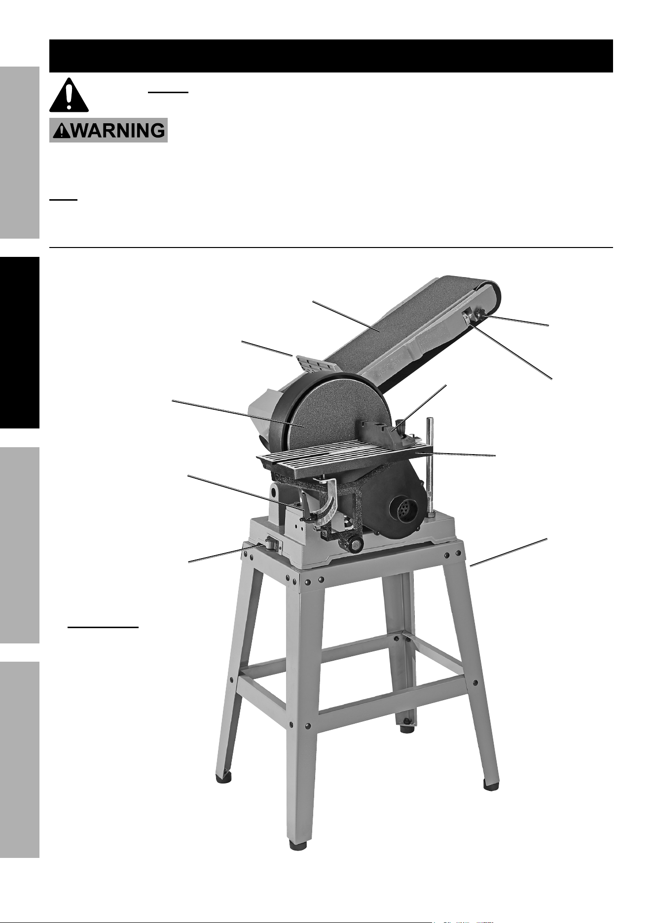
tool Stand assembly
1. Align the two mounting holes located at each end of
a Short Top Frame (73) with the mounting holes
located at the top of two Legs (74).
2. Insert four M6 x12 Carriage Bolts (81)
through the aligned mounting holes of the
Short Top Frame and two Legs. Attach
6 mm Flat Washers (82) and M6 Nuts (83)
to the Carriage Bolts and loosely tighten.
3. Align the mounting holes located at each end of a
Short Brace (76) with the mounting holes located
on the lower, inside edges of the two Legs.
4. Insert two M6 x12 Carriage Bolts through the
aligned mounting holes of the Short Brace and
two Legs. Attach 6 mm Flat Washers and M6 Nuts
to the Carriage Bolts and loosely tighten.
5. Repeat Steps #1 through #4 above to
attach the remaining Short Top Frame and
Short Brace to the two remaining Legs.
6. Align the two mounting holes located at
each end of a Long Top Frame (72) with
the mounting holes located at the top of
the two Leg assemblies.
7. Insert four M6 x12 Carriage Bolts through
the aligned mounting holes of the Long
Top Frame and the two Leg assemblies.
Attach 6 mm Flat Washers and M6 Nuts to
the Carriage Bolts and loosely tighten.
8. Align the mounting holes located at
each end of a Long Brace (75) with the
mounting holes located on the lower,
inside edges of the two Leg assemblies.
9. Insert two M6 x12 Carriage Bolts through
the aligned mounting holes of the Long
Brace and the two Leg assemblies. Attach
6 mm Flat Washers and M6 Nuts to the
Carriage Bolts and loosely tighten.
10. Repeat Steps #6 through #9 above to
attach the remaining Long Top Frame and
Long Brace to the two Leg assemblies.
11. Place the Tool Stand at the location
where it will be used. With the aid of
a corner square and a level, make
sure the top of the Tool Stand is level.
Then, wrench tighten all of the Nuts.
Short Short
top Frametop Frame
Short Short
BraceBrace
M6 x12 M6 x12
carriage carriage
BoltBolt
6 mm Flat
Washer
Leg
M6 nut
Long Long
BraceBrace
M6 x12 M6 x12
carriage carriage
BoltBolt
6 mm Flat
Washer
Leg
assembly
Leg
assembly
M6 nut
Long Long
top top
FrameFrame
Page 8 For technical questions, please call 1-888-866-5797. Item 59220
SaFEty OpEratiOn MaintEnancESEtup
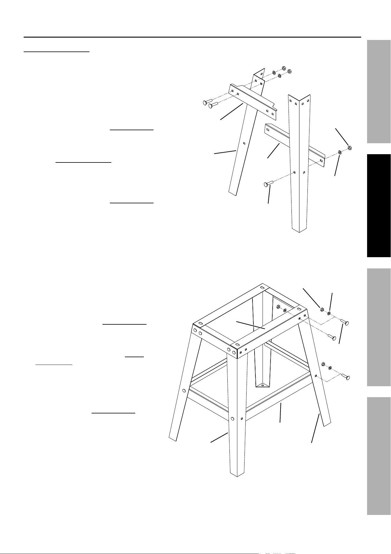
12. With assistance, carefully tip the
assembled Tool Stand onto its side.
13. Attach a Rubber Foot (79) to
the bottom of each Tool Stand
Leg using four Rubber Feet and
four sets of M8 x 25 Socket Head
Bolts (77), 8 mm Flat Washers
(78), and M8 Nuts (80).
14. Place the Tool Stand back
in its upright position.
Mounting Sander to tool Stand
1. With assistance, place the Base (66)
of the Belt/Disc Sander on top
of the assembled Tool Stand.
2. Align the four threaded mounting
holes on the Base with the
four mounting holes on the
top of the Tool Stand.
3. From underneath the Tool Stand,
secure the Base to the Stand
by inserting four sets of M8 x16
Hex Head Bolts (84), 8 mm Lock
Washers (85), and 8 mm Flat
Washers (86) upward through the
Stand’s four mounting holes.
4. Tighten the four Bolts securely
into the four threaded mounting
holes on the Base.
rubber Footrubber Foot
M8 x 25 M8 x 25
Socket Socket
Head Head
BoltBolt
8 mm
Flat
Washer
M8 M8
nutnut
BaseBase
M8 x 16 M8 x 16
Hex Head Hex Head
BoltBolt
8 mm Flat
Washer
8 mm Lock
Washer
Mounting
Hole
tool Stand
Page 9For technical questions, please call 1-888-866-5797.Item 59220
SaFEtyOpEratiOnMaintEnancE SEtup
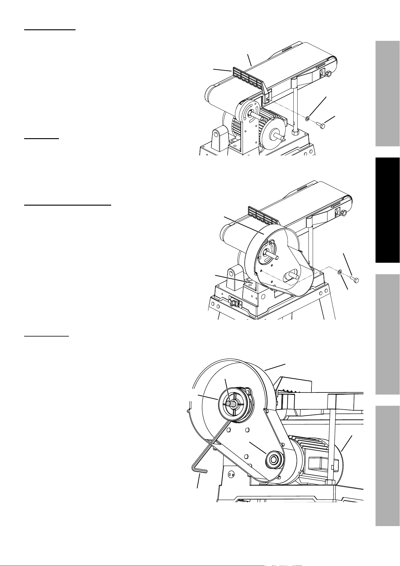
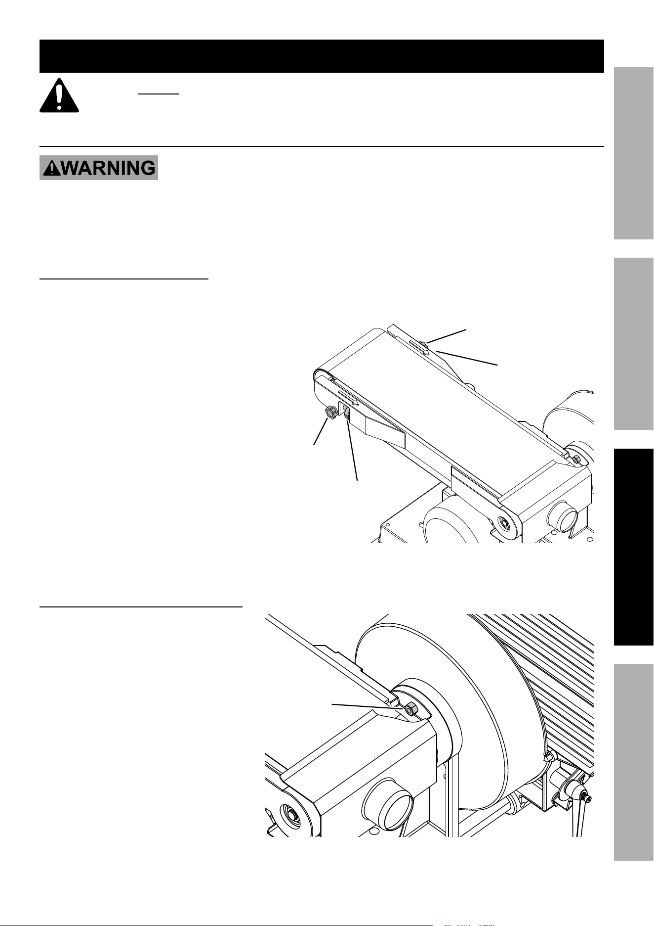
Mounting Fence
1. The Fence (99) fits across the top of the
Sanding Belt to prevent workpiece from
moving to the rear when sanding.
2. Align the mounting hole on the Fence
with the threaded mounting hole on
the Sanding Belt Frame (100).
3. Secure Fence in place using M8 x 20 Hex
Head Bolt (97) and 8 mm Flat Washer (98).
WarninG! tO prEVEnt SEriOuS inJury:
Adjust Fence height to avoid contact with
Sanding Belt and allow free Belt movement.
Install Disc / Pulley Housing
1. Remove the Disc Guard (33) from the
Disc/Pulley Housing (22).
2. Attach the Disc/Pulley Housing to
the four threaded mounting holes on
the Support Bracket (19) using four
sets of M8 x12 Hex Head Bolts (28)
and 8 mm Flat Washers (27).
install pulleys
1. Loosen the M8 x10 mm Set Screw (23)
on the Drive Pulley (24). Slide the Drive
Pulley onto the drive shaft, with the
5 x 55 mm Machine Key (12) lined up with
the slot on the Pulley. Be sure the Key
stays in the correct position, all the way
through the Pulley.
2. Loosen the M8 x10 mm Set Screw (25)
on the Motor Pulley (26). Slide the
Motor Pulley onto the motor shaft, with
the 5 x 25 mm Machine Key (93) lined
up with the slot on the Pulley. Be sure
the Key stays in the correct position,
all the way through the Pulley.
3. Align the Motor Pulley with the Drive Pulley.
4. Use a hex wrench through the slot
in the Disc/Pulley Housing to tighten
the Set Screw on the Drive Pulley.
5. Tighten the Set Screw on the Motor Pulley.
Sanding Sanding
Belt FrameBelt Frame
Fence
M8 x 20 M8 x 20
Hex Head Hex Head
BoltBolt
8 mm Flat
Washer
Disc / Pulley Disc / Pulley
HousingHousing
8 mm
Flat
Washer
M8 x12 M8 x12
Hex Head Hex Head
BoltBolt
Support
Bracket
Disc / Pulley
Housing
Drive Drive
pulleypulley
Drive Drive
ShaftShaft
Motor
pulley
Hex
Wrench
Motor
Page 10 For technical questions, please call 1-888-866-5797. Item 59220
SaFEty OpEratiOn MaintEnancESEtup
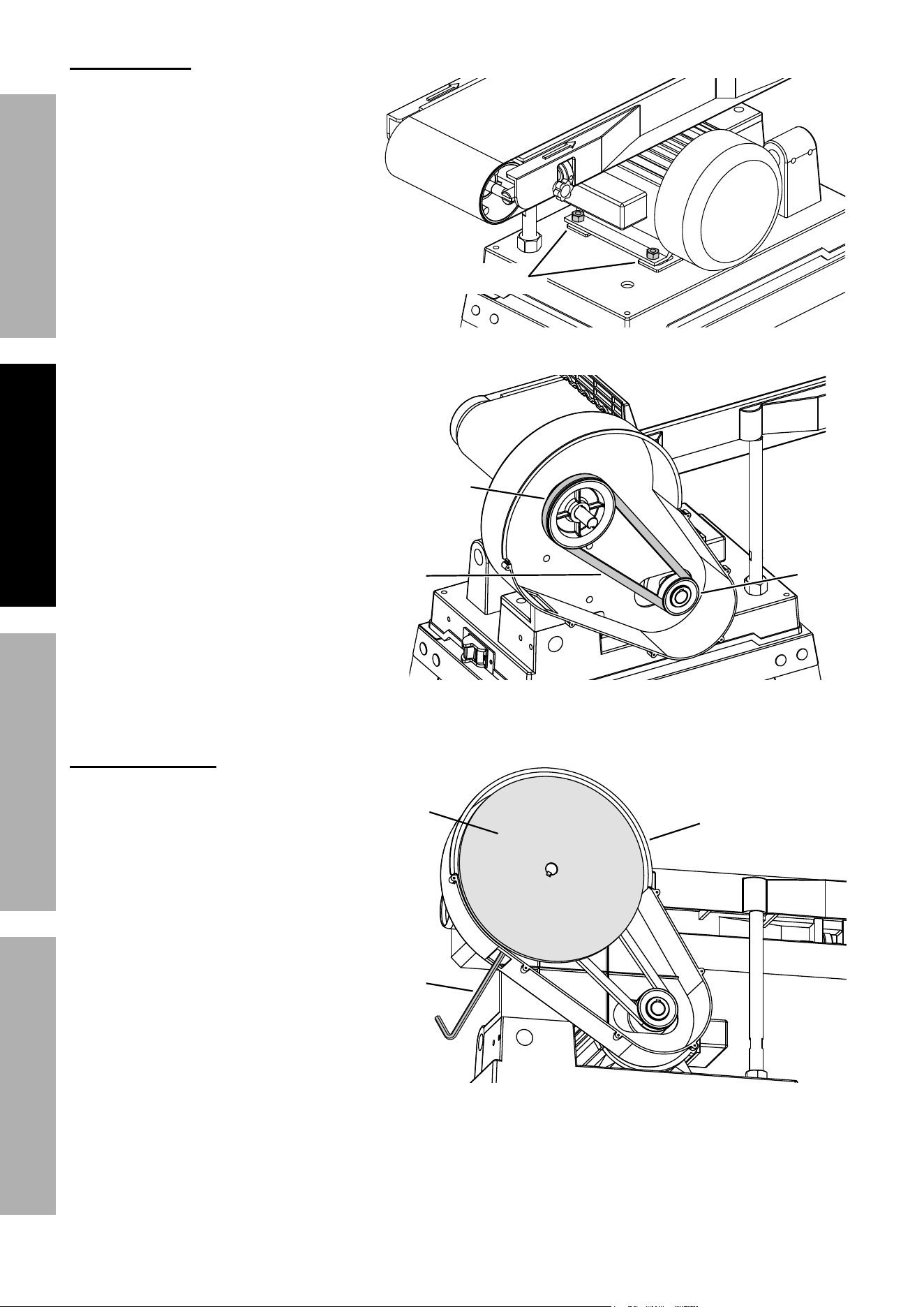
install Drive Belt
1. Loosen the four M8 x 20 Motor
Mount Bolts (91) that hold the
Motor (94) just enough to let the
Motor move.
2. Move the Motor forward toward the
Drive Pulley enough to allow the
Drive Belt (29) to slip on over the
Drive and Motor Pulleys. Make
sure the Belt is properly seated
in the grooves of both Pulleys.
3. Tighten the Drive Belt by
moving the Motor backward
away from the Drive Pulley.
4. Hold the Motor in place and retighten
the four Motor Mount Bolts.
5. Check Drive Belt tension by
squeezing both sides of the
Belt toward each other. When
properly adjusted, the Belt
should deflect anywhere from
1/8 to 1/4 inch. Make sure the
Belt is properly seated in the
grooves of both Pulleys.
install Backing Disc
1. Loosen the M8 x10 mm Set
Screw (31) on the Backing
Disc (30).
2. Slide the Backing Disc onto
the drive shaft so that it’s flush
with the end of the shaft.
3. Use a hex wrench through
the slot in the Disc/Pulley
Housing to tighten the Set
Screw on the Backing Disc.
Motor Motor
Mount BoltsMount Bolts
Motor
Drive
Belt
Drive Drive
pulleypulley
Motor Motor
pulleypulley
Disc / Pulley
Housing
Backing Backing
DiscDisc
Hex
Wrench
Page 11For technical questions, please call 1-888-866-5797.Item 59220
SaFEtyOpEratiOnMaintEnancE SEtup
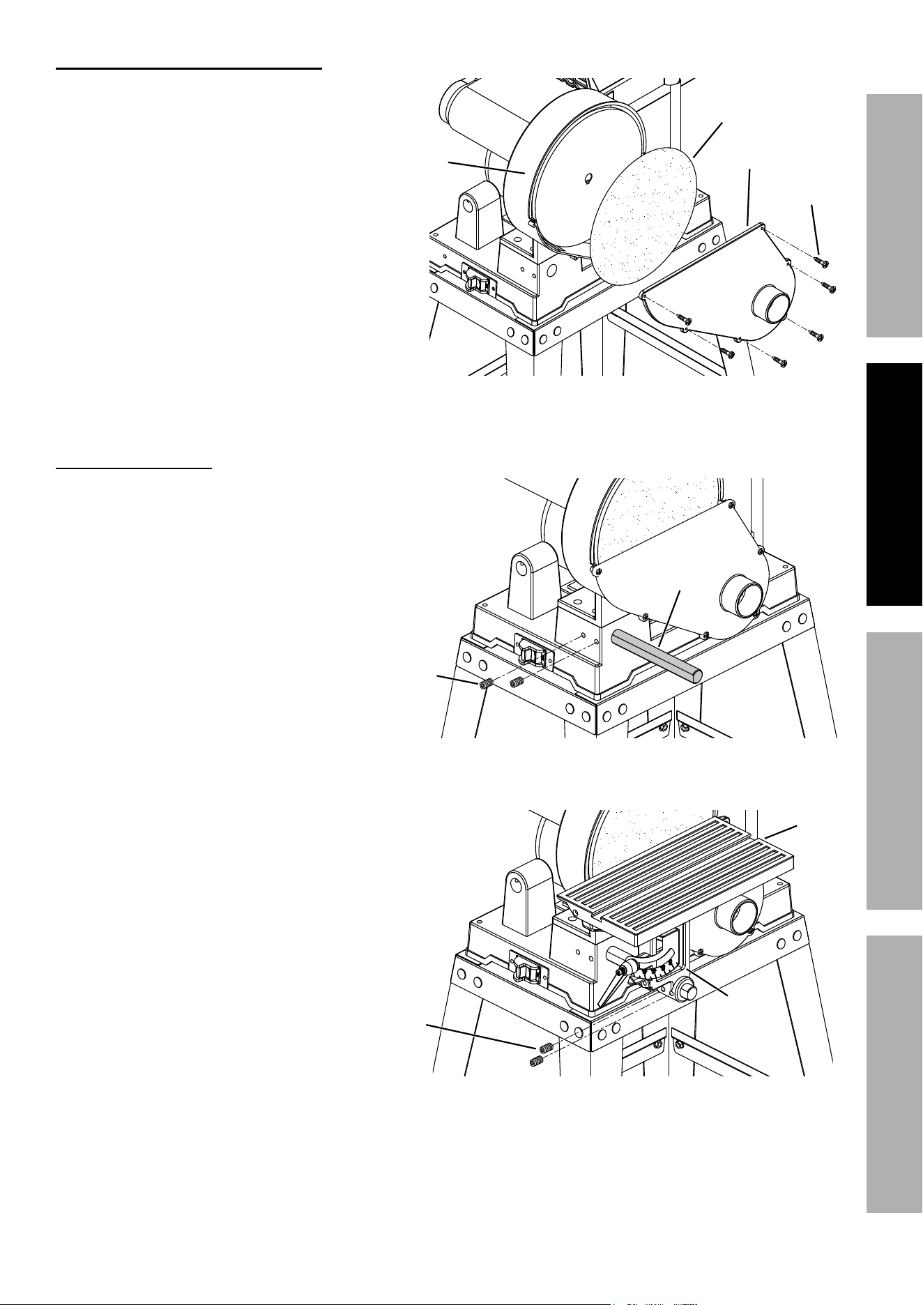
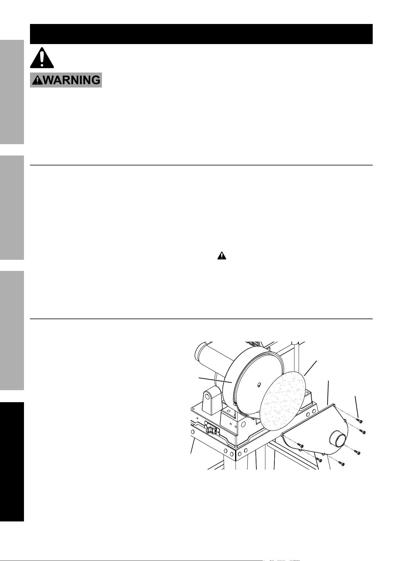
install Sanding Disc and Disc Guard
1. Wipe down the Backing Disc with
denatured alcohol to remove any
residue and ensure a secure bond.
2. Remove backing from
Sanding Disc (32).
3. Align perimeter of Sanding Disc over
the Backing Disc and press Sanding
Disc firmly onto the Backing Disc.
4. Position Disc Guard (33) against
Disc/Pulley Housing, aligning holes
in Guard with mounting holes in
Housing. Fasten securely using
six Self-Tapping Screws (55).
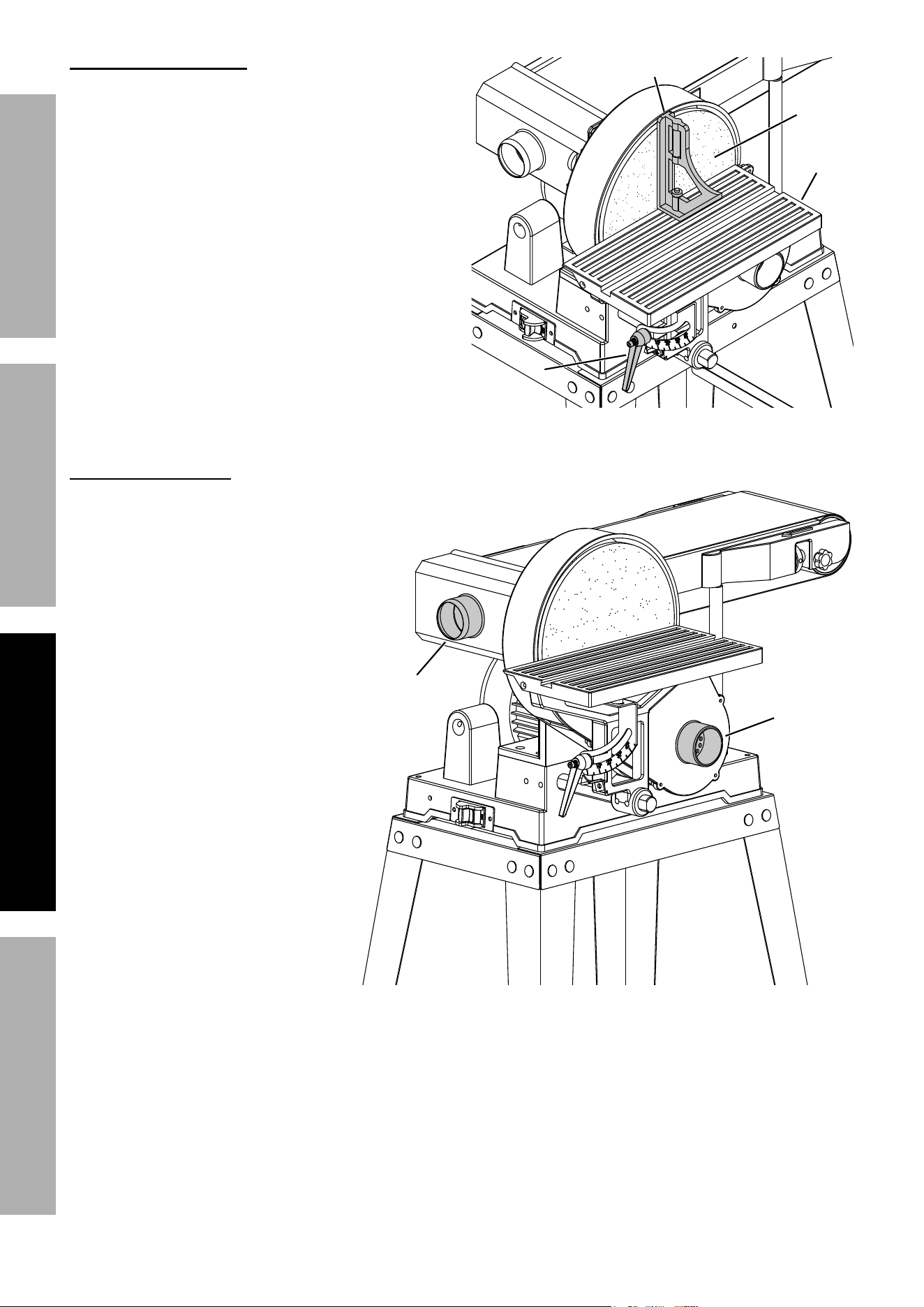
Mounting Work table
1. Insert the round end of the Table Support
Bar (56) into the mounting hole on the side
of the Base (66) as shown.
2. Turn the Support Bar so the flat side
of the Bar is facing the Set Screws.
3. Tighten the two M8 x 20 mm Set
Screws (65) on the side of the
Base to secure the Bar.
4. Slide the Work Table assembly
onto the Table Support Bar.
5. Adjust the Table so the edge is a
maximum of 1/16 inch from the
Sanding Disc.
6. Tighten the two M8 x10 mm
Set Screws (50) on the
Table Support (51) to
secure the Work Table.
Sanding
Disc
Screw
Disc
Guard
Backing
Disc
Disc /
pulley
Housing
table Support
Bar
M8 x 20 M8 x 20
Set Set
ScrewScrew
M8 x10
Set
Screw
Work
table
table
Support
Page 12 For technical questions, please call 1-888-866-5797. Item 59220
SaFEty OpEratiOn MaintEnancESEtup
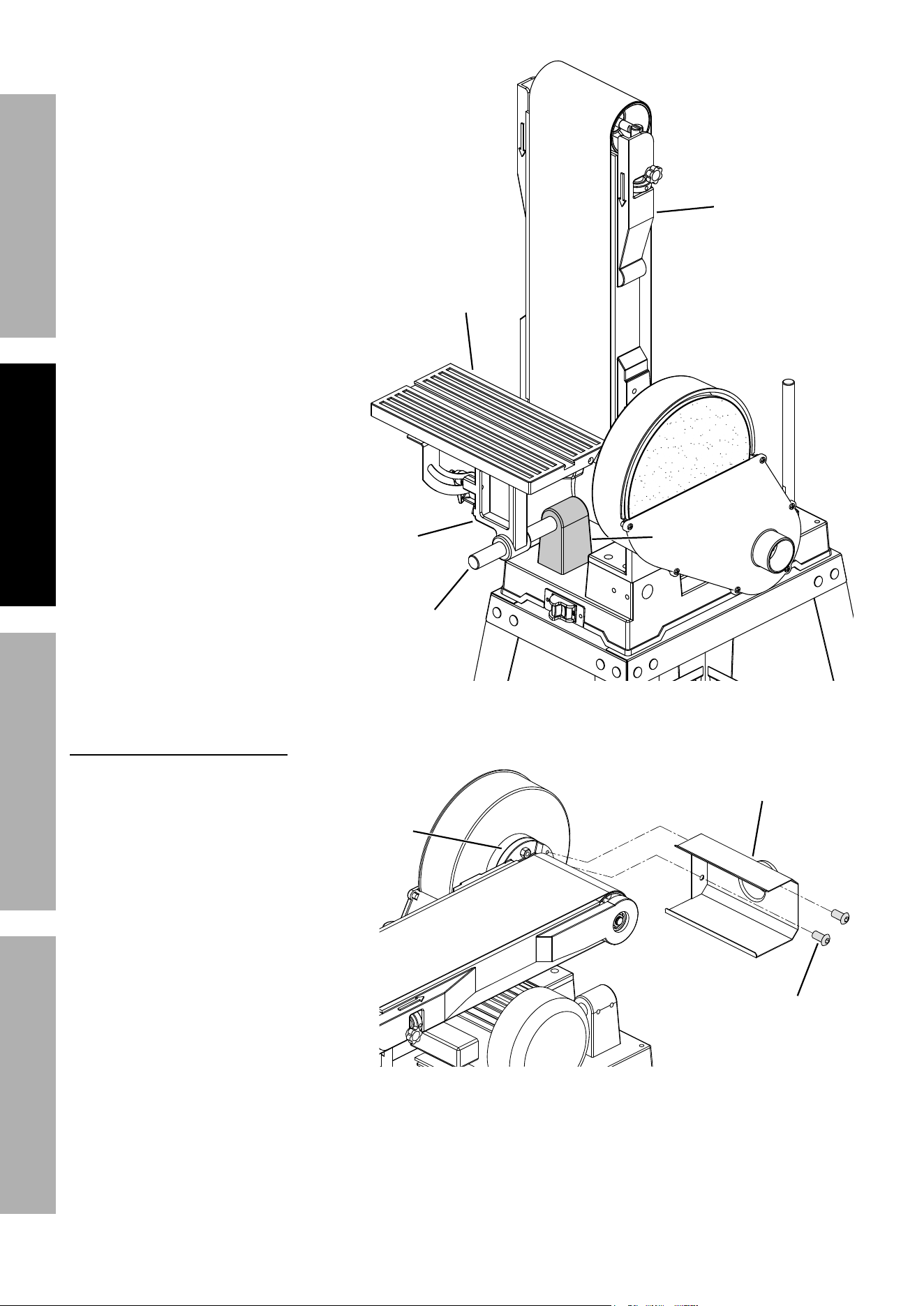
7. When using the Belt Sander in its
vertical position, the Work Table may
be repositioned to the front of the
Sanding Belt Frame.
8. To reposition the Work Table,
loosen the two M8 x 20 mm Set
Screws on the side of the Base
and remove the Work Table with
the attached Table Support Bar.
9. Insert the Table Support Bar
into the mounting hole on
the Mounting Bracket and
tighten the two M8 x10 mm Set
Screws on the Bracket.
10. Loosen the two M8 x10 mm Set
Screws on the Table Support
and adjust the Work Table so
the edge is a maximum of 1/16
inch from the Sanding Belt.
11. Tighten the two M8 x10 mm Set
Screws on the Table Support
to secure the Work Table.
install Sanding Belt Dust port
1. Align the two mounting holes in
the Sanding Belt Dust Port (10)
with the two threaded mounting
holes on the Support Bracket.
2. Attach the Dust Port to the
Bracket using two M6 x10
Socket Pan Head Screws (9).
table
Support
Bar
Work
table
table
Support
Mounting
Bracket
Sanding Sanding
Belt FrameBelt Frame
M6 x10
Socket pan
Head Screw
Support
Bracket
Sanding Belt
Dust port
Page 13For technical questions, please call 1-888-866-5797.Item 59220
SaFEtyOpEratiOnMaintEnancE SEtup
Operating instructions
read the EntirE iMpOrtant SaFEty inFOrMatiOn section at the beginning of this
manual including all text under subheadings therein before set up or use of this product.
tool Set up
tO prEVEnt SEriOuS inJury FrOM acciDEntaL OpEratiOn:
turn the power Switch of the tool off and unplug the tool from its electrical outlet
before performing any procedure in this section.
tO prEVEnt SEriOuS inJury:
DO nOt OpEratE WitH any GuarD DiSaBLED, DaMaGED, Or rEMOVED.
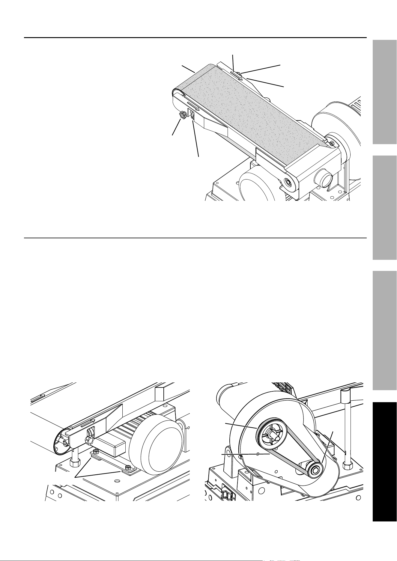
adjusting Sanding Belt tracking
1. Make sure the Belt Tracking Dials are evenly
tightened on both sides and that the Sanding
Belt is sufficiently tight.
2. Spin the Belt down by hand to note any
gross side to side movement. The Belt
should remain centered on the front and rear
Drums. If the Belt starts moving to the side
of either Drum, it needs to be adjusted.
3. If the Belt moves to the left, increase
tension on the left side Tracking Dial.
If the Belt moves to the right, increase
tension on the right side Tracking Dial.
4. To fine tune tracking, turn the Sander
on and immediately off again after
adjustment to check alignment.
5. If necessary, continue to adjust the
Belt Tracking Dials until the Belt rides
in the center of the front and rear Drums,
then tighten the Tracking Lock Knobs.
changing Sanding Belt Frame position
The Sanding Belt Frame can be used in
a horizontal or vertical position or at any
angle in-between. To change the Belt
Frame position, do the following:
1. Loosen the Sanding Belt Frame Lock
Nut and raise the Sanding Belt Frame
to the desired vertical position/angle.
2. After positioning, wrench tighten the
Lock Nut securely to prevent the
Sanding Belt Frame from slipping.
tracking
Lock
Knob
tracking Lock
Knob
Belt
tracking
Dial
Belt
tracking Dial
Sanding
Belt Frame
Lock nut
Page 14 For technical questions, please call 1-888-866-5797. Item 59220
SaFEty OpEratiOn MaintEnancESEtup
Leveling the Work table
For accurate end sanding the Work Table must be
square to the Sanding Disc.
1. Place a combination square or framing square
(not included) on the Table so that the square
touches the Sanding Disc. If the Table is 90°
to the Sanding Disc, the Table is level. Always
maintain a maximum of 1/16" clearance
between the Table and the Sanding Disc.
2. If the Table is not 90° to the Sanding Disc
pad, loosen the Work Table Lock Lever
and tilt the Table until it is square with the
Sanding Disc. Tighten the Lock Lever.
Dust collection Setup
To minimize dust, the Sander is equipped
with two Dust Ports for connecting
to a dust collection system.
1. When using the Belt Sander,
connect a 2" dust collection hose
and hose clamp from the Sanding
Belt Dust Port to a shop vacuum
or dust collection system (hose
and system not included).
2. When using the Disc Sander,
connect a 2" dust collection hose
and hose clamp from the Sanding
Disc Dust Port to a shop vacuum
or dust collection system (hose
and system not included).
3. Periodically check the Dust
Collection Ports for sawdust
buildup that would reduce the
dust collection efficiency.
4. It is recommended to wear a dust
mask or respirator even when
using a dust collection system.
Work Work
table Locktable Lock
Lever
Work
table
SquareSquare
Sanding
Disc
Sanding
Belt Dust
port
Sanding
Disc Dust
port

Page 15For technical questions, please call 1-888-866-5797.Item 59220
SaFEtyOpEratiOnMaintEnancE SEtup
Work area Set up
1. Designate a work area that is clean and well
lit. The work area must not allow access by
children or pets to prevent distraction and injury.
2. There must not be objects, such as utility lines,
nearby that will present a hazard while working.
3. Route the power cord along a safe route to reach
the work area without creating a tripping hazard or
exposing the power cord to possible damage. The
power cord must reach the work area with enough
extra length to allow free movement while working.
General Operating instructions
1. Make sure that the Switch is in the off-position,
then plug in the tool.
2. Turn on the shop vacuum or dust
collection system (if used).
3. Insert Safety Key into Switch.
4. Make sure nothing is contacting the Sanding
Disc or Belt, then turn on the Switch.
5. When using the Disc Sander, only use the LEFT
side of the Sanding Disc (as you face it) to sand.
The Sanding Disc turns counterclockwise and
using the right side could cause kickback.
6. Use two hands and hold workpiece securely against
the Fence / Work Table at all times. Press the
workpiece against the Belt/Disc to start sanding.
Keep the workpiece moving for a better finish.
7. Occasionally check the Sanding Belt and Sanding
Disc for tears, wear, or fraying. Replace used or
worn sanding belts or discs when necessary.
8. After use, turn off the tool, remove the
Safety Key from the Switch, and disconnect
from the power supply. Clean and store
the tool indoors out of children's reach.
Page 16 For technical questions, please call 1-888-866-5797. Item 59220
SaFEty OpEratiOn MaintEnancESEtup
Maintenance and Servicing
procedures not specifically explained in this manual must
be performed only by a qualified technician.
tO prEVEnt SEriOuS inJury FrOM acciDEntaL OpEratiOn:
turn the power Switch of the tool off and unplug the tool from its electrical outlet
before performing any procedure in this section.
tO prEVEnt SEriOuS inJury FrOM tOOL FaiLurE:
Do not use damaged equipment. if abnormal noise or vibration
occurs, have the problem corrected before further use.
cleaning, Maintenance, and Lubrication
1. BEFOrE EacH uSE, inspect the general
condition of the tool. Check for:
• loose hardware
• misalignment or binding of moving parts
• cracked or broken parts
• damaged electrical wiring
• any other condition that may
affect its safe operation.
2. aFtEr uSE, turn off the tool, remove the
Safety Key from the Switch, and disconnect
its power supply. Then, wipe external
surfaces of the tool with clean cloth.
3. Apply a light coat of paste wax to the Work
Table to make feeding material easier.
4. Periodically, wear ANSI-approved safety
goggles and NIOSH-approved breathing
protection and blow dust and debris out of
the motor vents using dry compressed air.
5. The Bearings on this Sander are sealed
and do not require lubrication.
6. WarninG! tO prEVEnt SEriOuS
inJury: if the supply cord of this power
tool is damaged, it must be replaced only
by a qualified service technician.
Sanding Disc replacement
1. Remove the Work Table if it is mounted in
front of the Sanding Disc.
2. Remove the Screws holding the Disc
Guard in place and remove the Guard.
3. Peel off old Sanding Disc.
4. Wipe down the Backing Disc with
denatured alcohol to remove any
residue and ensure a secure bond.
5. Remove backing from new Sanding Disc.
6. Align perimeter of new Sanding Disc
over the Backing Disc and press Sanding
Disc firmly onto the Backing Disc.
7. Position the Disc Guard back in place
against the Disc/Pulley Housing. Replace
the Screws and fasten securely.
Sanding
Disc
Screw
Disc
Guard
Backing
Disc
Disc /
pulley
Housing
Page 17For technical questions, please call 1-888-866-5797.Item 59220
SaFEtyOpEratiOnMaintEnancE SEtup
Sanding Belt replacement
1. Loosen the Tracking Lock Knobs on
both sides of the Sanding Belt Frame.
Loosen the Belt Tracking Dials to
release tension on the Sanding Belt.
2. Push down on the upper Drum and pull
the old Sanding Belt off the Drums from
the side opposite the Sanding Disc.
3. Slide a new 6" x 48" Sanding Belt
onto the Drums with the arrows on
the inside of the Belt pointing in the
direction of rotation as indicated by
the directional arrows on the tool.
4. Center the Belt correctly on both
Drums. Tighten the Tracking Dials and
Lock Knobs on both sides to tighten
the Belt to the Sanding Belt Frame.
5. Before using, check the new Sanding
Belt for alignment. Refer to Adjusting
Sanding Belt Tracking on page 13.
Drive Belt Replacement / Tensioning
1. Remove the Work Table if it is mounted
in front of the Sanding Disc.
2. Remove the Screws holding the Disc
Guard in place and remove the Guard.
3. Loosen the M8 x10 mm Set Screw on the Backing
Disc and slide the Disc off the drive shaft.
4. Loosen the four M8 x 20 Motor Mount Bolts that
hold the Motor just enough to let the Motor move.
5. Move the Motor forward toward the Drive
Pulley enough to allow the Drive Belt to slip
off over the Drive and Motor Pulleys.
6. Remove the old Drive Belt. Place the new Drive
Belt onto the Pulleys, making sure the Belt is
properly seated in the grooves of both Pulleys.
7. Tighten the Drive Belt by moving the
Motor backward away from the Drive
Pulley. Hold the Motor in place and
retighten the four Motor Mount Bolts.
8. Check Drive Belt tension by squeezing both sides
of the Belt toward each other. When properly
adjusted, the Belt should deflect anywhere from
1/8 to 1/4 inch. Make sure the Belt is properly
seated in the grooves of both Pulleys.
9. When Belt tensioning is complete, reinstall
the Backing Disc and Disc Guard.
Motor Motor
Mount BoltsMount Bolts
Motor
Drive
Belt
Drive Drive
pulleypulley
Motor Motor
pulleypulley
tracking
Lock
Knob
tracking Lock
Knob
Belt
tracking
Dial
Belt
tracking Dial
Sanding
Belt
Directional arrow

Page 18 For technical questions, please call 1-888-866-5797. Item 59220
SaFEty OpEratiOn MaintEnancESEtup
troubleshooting
problem possible causes Likely Solutions
Belt/Disc Sander
does not turn on
1. Not plugged in.
2. No power at outlet.
3. Safety Key not inserted into Switch.
4. Switch is not turned ON.
1. Plug in Sander.
2. Check power at outlet and/or circuit breaker.
3. Insert Safety Key into Switch.
4. Turn on the Switch.
Motor slows
when sanding
1. Drive Belt too tight.
2. Applying too much pressure
while sanding.
1. Adjust Drive Belt tension. Refer to Drive Belt
Replacement / Tensioning on page 17.
2. Use less pressure.
Wood burns
while sanding
1. Sanding Disc or Belt may be
loaded with dirt or debris.
2. Applying too much pressure
while sanding.
1. Clean or replace Disc or Belt using
instructions in this manual.
2. Use less pressure.
Follow all safety precautions whenever diagnosing or servicing
the tool. Disconnect power supply before service.

Page 19For technical questions, please call 1-888-866-5797.Item 59220
SaFEtyOpEratiOnMaintEnancE SEtup
pLEaSE rEaD tHE FOLLOWinG carEFuLLy
THE MANUFACTURER AND/OR DISTRIBUTOR HAS PROVIDED THE PARTS LIST AND ASSEMBLY DIAGRAM
IN THIS MANUAL AS A REFERENCE TOOL ONLY. NEITHER THE MANUFACTURER OR DISTRIBUTOR
MAKES ANY REPRESENTATION OR WARRANTY OF ANY KIND TO THE BUYER THAT HE OR SHE IS
QUALIFIED TO MAKE ANY REPAIRS TO THE PRODUCT, OR THAT HE OR SHE IS QUALIFIED TO REPLACE
ANY PARTS OF THE PRODUCT. IN FACT, THE MANUFACTURER AND/OR DISTRIBUTOR EXPRESSLY
STATES THAT ALL REPAIRS AND PARTS REPLACEMENTS SHOULD BE UNDERTAKEN BY CERTIFIED AND
LICENSED TECHNICIANS, AND NOT BY THE BUYER. THE BUYER ASSUMES ALL RISK AND LIABILITY
ARISING OUT OF HIS OR HER REPAIRS TO THE ORIGINAL PRODUCT OR REPLACEMENT PARTS
THERETO, OR ARISING OUT OF HIS OR HER INSTALLATION OF REPLACEMENT PARTS THERETO.

Page 20 For technical questions, please call 1-888-866-5797. Item 59220
SaFEty OpEratiOn MaintEnancESEtup
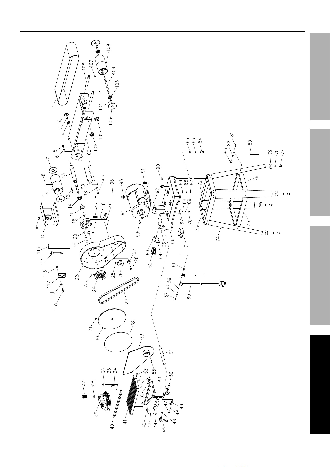
parts List and Diagram
parts List
part Description Qty
1 Sanding Belt 6 x 48" 1
2 Bearing Cover 1
3 C-Ring 12 mm 1
4 Ball Bearing 6201 1
5 Nut M8 2
6 Lock Washer 8 mm 2
7 Drum Cover 2
8 Set Screw M8 x10 2
9 Socket Pan Head Screw M6 x10 2
10 Sanding Belt Dust Port 1
11 Drive Drum 1
12 Machine Key 5 x 55 mm 1
13 Drive Shaft 1
14 Ball Bearing 6003-2ZN 1
15 Bearing Snap Ring 1
16 C-Ring 17 mm 1
17 Hex Head Bolt M8 x 25 4
18 Flat Washer 8 mm 4
19 Support Bracket 1
20 Spacer Plate 1
21 Carriage Bolt M8 x 40 2
22 Belt House 1
23 Set Screw M8 x10 1
24 Drive Pulley 1
25 Set Screw M8 x10 1
26 Motor Pulley 1
27 Washer 8 mm 4
28 Hex Head Bolt M8 x12 4
29 V-Belt 1
30 Aluminum Disc 1
31 Set Screw M8 x10 1
32 Sanding Disc 9" 1
33 Disc Guard 1
34 Pointer 1
35 Flat Washer 4 mm 1
36 Pan Head Screw M4 x 6 1
37 Miter Gauge Lock Knob 1
38 Flat Washer 6 mm 1
39 Miter Gauge 1
40 Guide Bar 1
41 Work Table 1
42 Angle Plate 1
43 Washer 8mm 1
44 Hex Head Bolt M8 x12 1
45 Work Table Lock Handle 1
46 Flat Washer 8 mm 1
47 Pan Head Screw M5 x12 1
48 Flat Washer 5 mm 1
49 Pointer 1
50 Set Screw M8 x10 2
51 Work Table Support 1
52 Nut 2
53 Flat Head Bolt M5 x 40 2
54 nut M5 2
55 Thread Forming Screw 4
56 Support Bar 1
57 Pan Head Screw M5 x 10 1
58 Lock Washer 5 mm 1
part Description Qty
59 Flat Washer 5 mm 1
60 Power Cord 1
61 Serriated Washer 1
62 Switch 1
63 Thread Forming Screw 2
64 Switch Plate 1
65 Set Screw M8 x 20 2
66 Base 1
67 Cord Clamp Plate 2
68 Flat Washer 5 mm 2
69 Lock Washer 5 mm 2
70 Pan Head Screw M5 x12 2
71 Switch Box 1
72 Long Top Frame 2
73 Short Top Frame 2
74 Leg 4
75 Long Brace 2
76 Short Brace 2
77 Socket Head Bolt M8 x 25 4
78 Flat Washer 8 mm 4
79 Rubber Foot 4
80 Nut M8 4
81 Carriage Bolt M6 x12 24
82 Flat Washer 6 mm 24
83 Nut M6 24
84 Hex Head Bolt M8 x16 4
85 Lock Washer 8 mm 4
86 Flat Washer 8 mm 4
87 Nut M8 4
88 Lock Washer 8 mm 4
89 Flat Washer 8 mm 4
90 Strain Relief 2
91 Hex Head Bolt M8 x 20 4
92 Set Screw M8 x10 2
93 Machine Key 5 x 25 mm 1
94 Motor 1
95 Nut M16 x 1.5 1
96 Support Bar 1
97 Hex Head Bolt M8 x 20 1
98 Flat Washer 8 mm 1
99 Work Stop 1
100 Sanding Belt Frame 1
101 Lock Knob 2
102 Belt Tracking Dial 2
103 Drum Cover 2
104 C-Ring 12 mm 2
105 Ball Bearing 6201 2
106 Shaft 1
107 Set Screw M5 x 6 1
108 Adjusting Shaft 2
109 Idler Drum 1
110 Pan Head Screw M4 x 8 2
111 Flat Washer 4 mm 2
112 Wrench Storage 1
113 Nut M4 2
114 Open End Wrench 10-13 mm 1
115 Hex Wrench 4 mm 1
Page 21For technical questions, please call 1-888-866-5797.Item 59220
SaFEtyOpEratiOnMaintEnancE SEtup
assembly Diagram

Page 22 For technical questions, please call 1-888-866-5797. Item 59220
SaFEty OpEratiOn MaintEnancESEtup
record product’s Serial number Here:
note: if product has no serial number, record month and year of purchase instead.
note: Some parts are listed and shown for illustration purposes only, and are not available
individually as replacement parts. Specify UPC 193175460417 when ordering parts.

Page 23For technical questions, please call 1-888-866-5797.Item 59220
SaFEtyOpEratiOnMaintEnancE SEtup
Limited 90 Day Warranty
Harbor Freight Tools Co. makes every effort to assure that its products meet high quality and durability standards,
and warrants to the original purchaser that this product is free from defects in materials and workmanship for the
period of 90 days from the date of purchase. This warranty does not apply to damage due directly or indirectly,
to misuse, abuse, negligence or accidents, repairs or alterations outside our facilities, criminal activity, improper
installation, normal wear and tear, or to lack of maintenance. We shall in no event be liable for death, injuries
to persons or property, or for incidental, contingent, special or consequential damages arising from the use of
our product. Some states do not allow the exclusion or limitation of incidental or consequential damages, so the
above limitation of exclusion may not apply to you. THIS WARRANTY IS EXPRESSLY IN LIEU OF ALL OTHER
WARRANTIES, EXPRESS OR IMPLIED, INCLUDING THE WARRANTIES OF MERCHANTABILITY AND FITNESS.
To take advantage of this warranty, the product or part must be returned to us with transportation charges
prepaid. Proof of purchase date and an explanation of the complaint must accompany the merchandise.
If our inspection verifies the defect, we will either repair or replace the product at our election or we may
elect to refund the purchase price if we cannot readily and quickly provide you with a replacement. We will
return repaired products at our expense, but if we determine there is no defect, or that the defect resulted
from causes not within the scope of our warranty, then you must bear the cost of returning the product.
This warranty gives you specific legal rights and you may also have other rights which vary from state to state.

26677 agoura road • calabasas, ca 91302 • 1-888-866-5797