BRU 108/178
UPRIGHT BIKE
Cardio Trainer
OWNER’S MANUAL
* This item is for consumer use only and it is not meant for commercial use.

This page intentionally left blank
General Information
BRU178/108 Page 1
Warranty
Body Flex Sports warrants your product for
a period of 1 year for the frame and 90 days
on all parts if the item is used for the intended
purpose, properly maintained and not used
commercially. Any alterations or incorrect
assembly of the product will void this warranty.
Proof of purchase must be presented for any
warranty validation (no exceptions). This
warranty applies to the original purchaser only
and is not transferable.
This warranty does not cover abuse or defects
caused during use, storage or assembly.
During the warranty period, Body Flex Sports
reserves the right to:
a). provide replacement parts to the
purchaser in an effort to repair the item.
b). repair the product returned to our
warehouse (at the purchaser’s cost).
c). replace the product if neither of the two
previously mentioned actions effect repair.
This warranty does not cover normal wear and
tear on upholstery.
Questions
If you have any questions concerning the
assembly of your item or if any parts are
missing, please DO NOT RETURN THE
ITEM TO THE STORE OR CONTACT THE
RETAILER. Our dedicated customer service
staff can help you with any questions you may
have regarding the assembly of this unit and
can also mail you replacement parts.
Customer Support
Customer Support is open 9:00 a.m. to 5:00
p.m. (Pacific Time) Monday through Friday.
Please contact us by any of the following
means.
Body Flex Sports, Inc.
21717 Ferrero Parkway, Walnut, CA 91789
Telephone: (888) 266 - 6789
Fax: (909) 598 - 6707
Email: info@bodyflexsports.com
Safety
Before you undertake any exercise program,
please be sure to consult with your doctor.
Frequent strenuous exercise should be
approved by your doctor and proper use
of your product is essential. Excessive or incorrect
training may result to health injuries. Please read
this manual carefully before commencing the
assembly of your product or starting to exercise.
• Please keep all children away from this item
when in use. Do not allow children to climb or
play on them when they are not in use.
• Supervise teenagers while they use this unit.
• For your own safety, always ensure that there
is at least 3 feet of free space in all directions
around your product while you are exercising.
• Regularly check to see that all nuts, bolts and
fittings are securely tightened. Periodically
check all moving parts for obvious signs of
wear or damage.
• Clean only with a damp cloth, do not use
solvent cleaners. If you are in any doubt, do
not use your product; contact CUSTOMER
SUPPORT.
• Before use, always ensure that your product
is positioned on a solid, flat surface. If
necessary, use a rubber mat underneath to
reduce the possibility of slipping.
•
Always wear appropriate clothing and
footwear such as training shoes when
exercising. Do not wear loose clothing that
could become caught in moving parts during
exercise.
• Do not use this unit if it is not functioning
properly or if it is not fully assembled.
• Do not use this unit for commercial purposes.
This unit is for home use only.
Storage and Use
Your product is intended for use in clean
dry conditions. You should avoid storage in
excessively cold or damp places as this may
lead to corrosion and other related problems.
Weight Limit
Your product is suitable for users weighing:
250 pounds or less.
• Before use, you must read and understand all
instructions & warnings stated in this Owner’s
Manual as well as posted on the equipment.
• It is the facility owner’s responsibility to properly
instruct users on the proper operation of the
equipment and to warn them of the potential
hazards.
• If at any time during exercise you feel faint, dizzy
or experience pain, stop and consult your
physician.
Assembling Tools
- Ruler with both metric and English measurements
- 2 x Adjustable Wrenches
- 1 x Philips (”Crosshead”) Screw Driver
•
Any adjustment devices that could interfere with
the user's movement on this unit should not be
left projecting.
Page 2
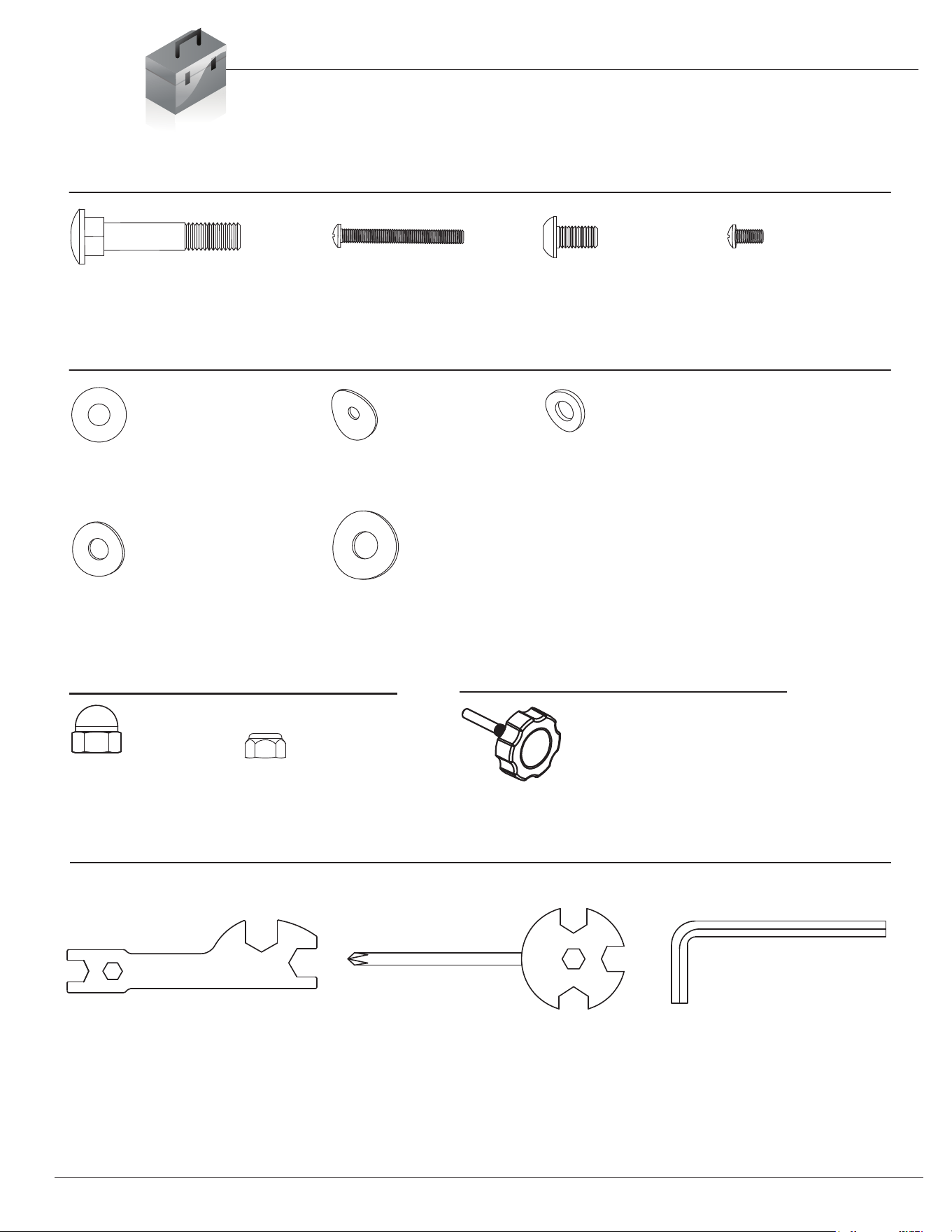
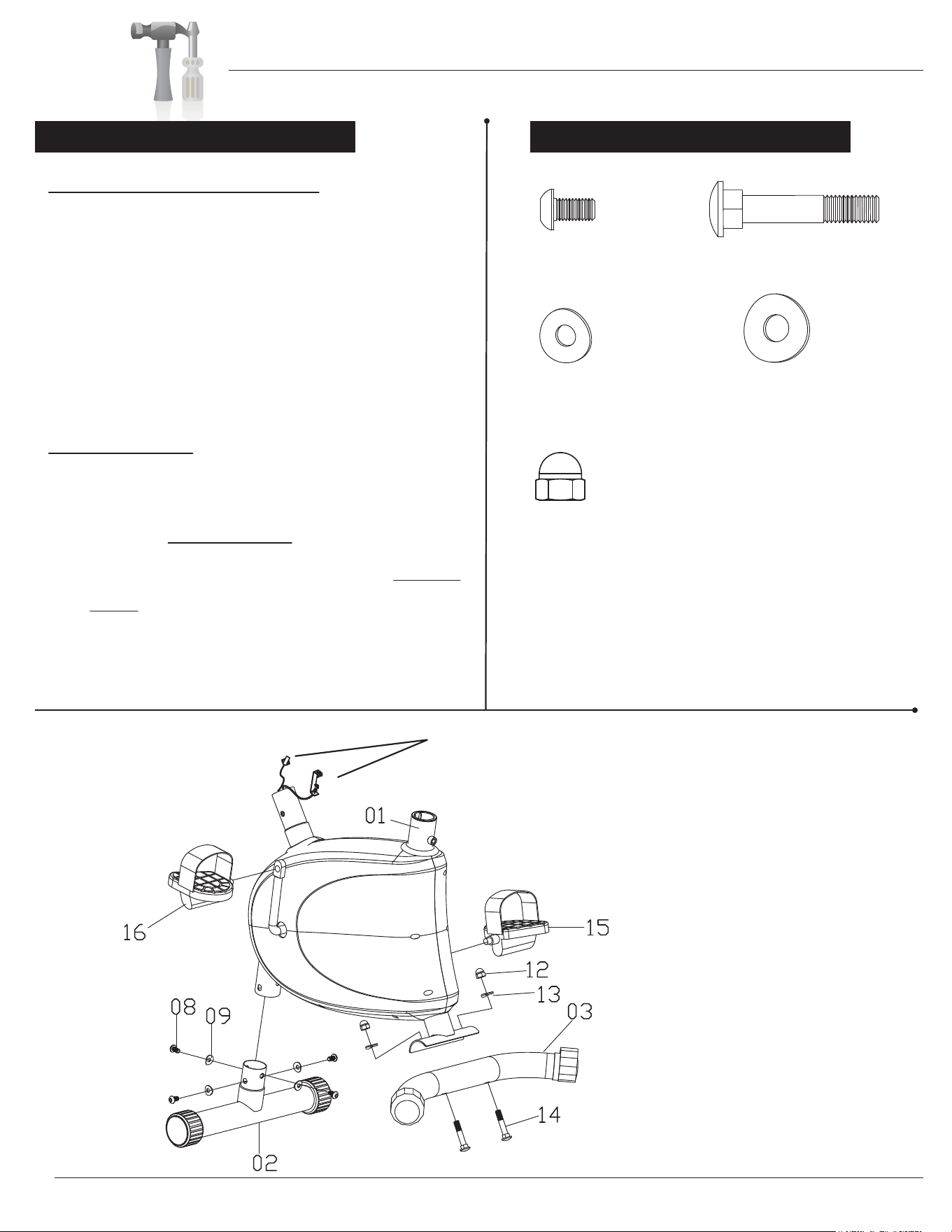
Hardware & Tool List
Bolts
Washers
Nuts
Tools
#14. Carriage Bolt (M10x57 mm)
[2 Pieces]
#23. Screw (M5x45 mm)
[1 Piece]
Pre-assembled
#08. Bolt (M8x15 mm)
[10 Pieces]
Pre-assembled
#34. Screw (M5x10 mm)
[2 Pieces]
Pre-assembled
#20. Washer (M8)
[3 Pieces]
Pre-assembled
#24. Arc Washer (M5)
[1 Piece]
Pre-assembled
#10. Arc Washer (M8)
[2 Pieces]
Pre-assembled
#09. Arc Washer (M8,φ20)
[8 Pieces]
Pre-assembled
#13. Arc Washer (M10)
[2 Pieces]
#12. Cap Nut (M10)
[2 Pieces]
#19. Nylon Nut (M8)
[3 Pieces]
Pre-assembled
Tool 1 (S10/S13/S17/S19)
[1 Piece]
Tool 2 (S10/S13/S14/S15)
[1 Piece]
Tool 3 (S6)
[1 Piece]
The following hardware is used to assemble your unit. Please take
a moment to familiarize yourself with these items.
PLEASE NOTE: some of these parts may have already been pre-assembled on your unit.
BRU178/108
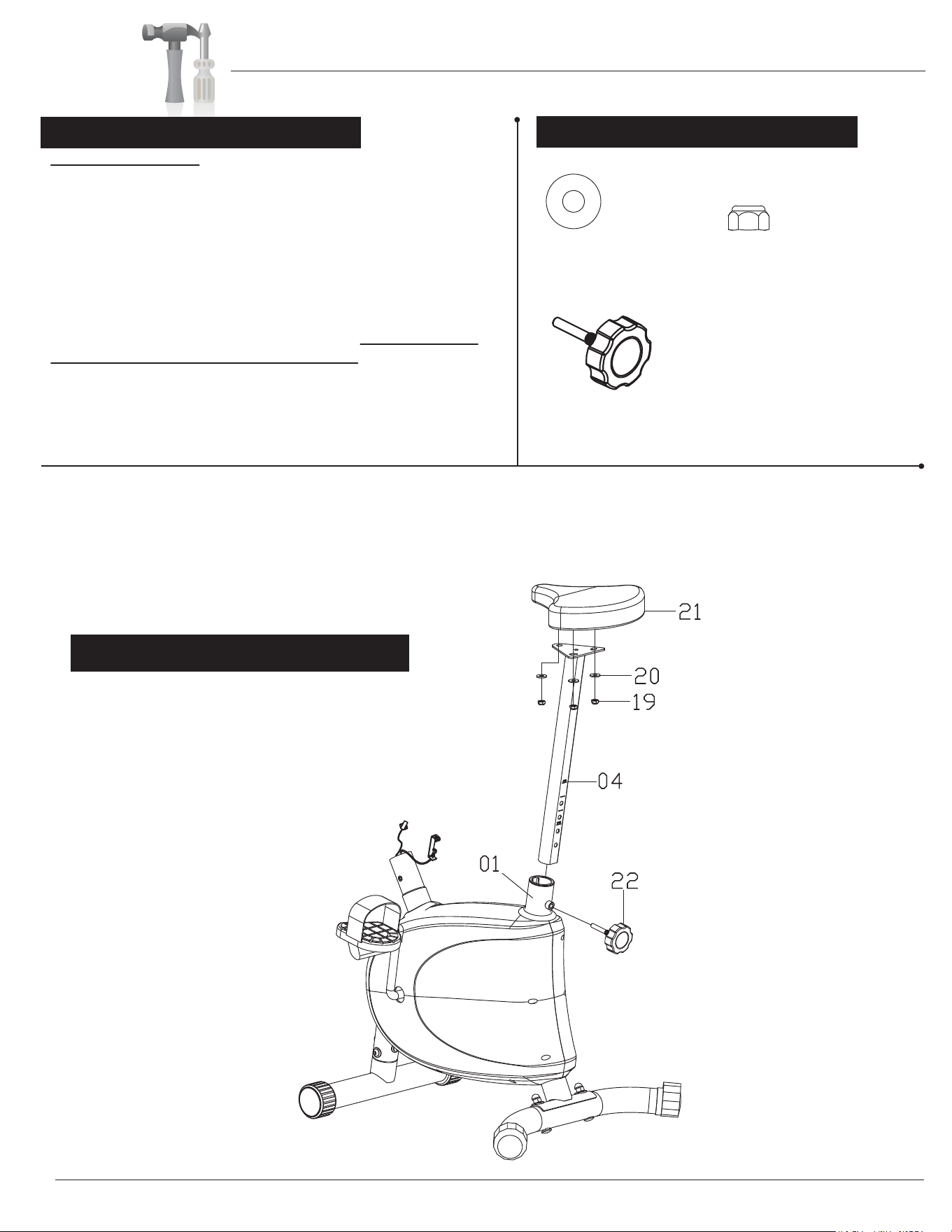
#22. Knob (M10x60mm)
[1 Piece]
Others

Page 3
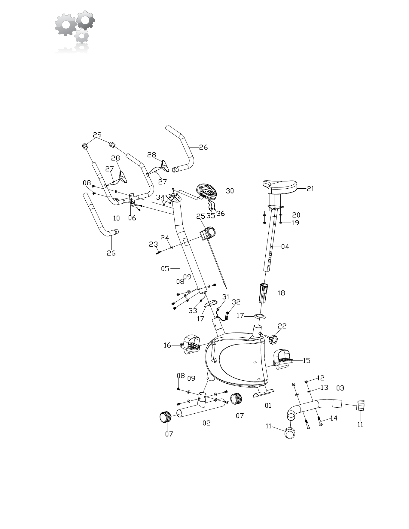
Parts Listing
The following parts list describes all of the parts illustrated on the
exploded diagram on the following page. Please note, most of
these parts are already pre-assembled on your unit.
# Description
01 Main Frame
02 Front Stabilizer
03 Rear Stabilizer
04 Seat Post
05 Front Post
06 Handlebar
07 End Cap for Front Stabilizer
08 Bolt (M8x15 mm)
09 Arc Washer (M8,φ20)
10 Arc Washer (M8)
11 End Cap for Rear Stabilizer
12 Cap Nut (M10)
13 Arc Washer (M10)
14 Carriage Bolt (M10x57 mm)
15 Right Pedal
16 Left Pedal
17 Round Cap (φ50)
18 Seat Post Sleeve
19 Nylon Nut (M8)
20 Washer (M8)
21 Seat
22 Knob (M10x60 mm)
23 Screw (M5x45 mm)
24 Arc Washer (M5)
25 Tension Controller
26 Foam
27 Screw (ST4.2x20 mm)
28 Hand Pulse Sensor
29 End Cap of Handlebar
30 Monitor
31 Monitor Wire (Lower)
32 Tension Controller Wire
33 Monitor Wire (Middle)
34 Screw (M5x10 mm)
35 Hand Pulse Wire
36 Monitor Wire (Upper)
BRU178/108
Page 4
Exploded Diagram
The following diagram is provided to help you familiarize yourself with the parts and
hardware that will be used during the assembly process. Please note that not all of the
parts and hardware you see here will be used while you are assembling the machine
because some of these items are already pre-installed. Please continue to the next
page to begin the assembly process and use this page only as a reference guide for
parts and hardware.
BRU178/108
Page 5
Assembly Instructions
As se m bl y S te p 1 Hardware Required
BRU178/108
A.) Front & Rear Stabilizer Assembly
Remove the Bolts (#08) and Arc Washers (#09) that are pre-
assembled on the Front Stabilizer (#02) and set them aside
for now. With the help of an assistant, insert the tip of the
Front Stabilizer (#02) up into the lower protruding base
tube on the Main Frame (#01). Please refer to illustration
below for reference. Secure using the previously removed
four Bolts (#08) and four Arc Washers (#09).
Attach the Rear Stabilizer (#03) to the back of the Main
Frame (#01) as illustrated and insert two Carriage Bolts
(#14). Then, secure with two Arc Washers (#13) followed
by two Cap Nuts (#12).
B.) Pedal Assembly
Please pay special attention to the turning direction of pedals to avoid
damaging/stripping pedal parts
.
Screw the Left Pedal (#16) to the left pedal crank located
on the Main Frame (#01) by turning the bolt head on the
Left Pedal (#16) counter-clockwise.
Screw the Right Pedal (#15) to the right pedal crank
by turning the bolt head on the Right Pedal (#15) clockwise.
Make sure these two wires are accessible and exposed (as shown) before
proceeding to the next step. If they have fallen inside the tube, use a
bent wire to “fish” them out.
#08. Bolt (M8x15 mm)
[4 Pieces]
#09. Arc Washer (M8,φ20)
[4 Pieces]
#12. Cap Nut (M10)
[2 Pieces]
#13. Arc Washer (M10)
[2 Pieces]
#14. Carriage Bolt (M10x57 mm)
[2 Pieces]
NOTE:
If labels designating the Left/Right Pedal are not
present, please check pedals closely for embossed
“L”/ “R” letter marks. These will be “L” / “R” letters
that are raised on the pedal material.
Assembly Instructions
Hardware Required
As s em bl y S te p 2
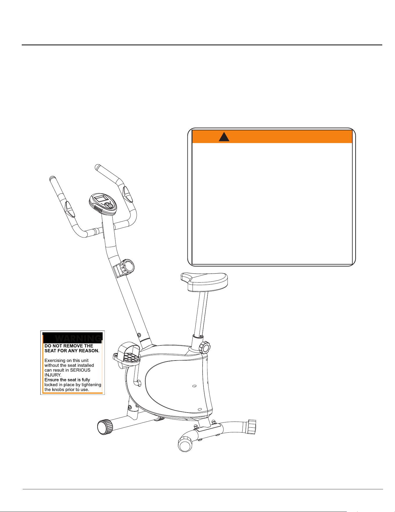
W A R N I N G
Do not remove the Seat (#21) for any
reason after you have installed it.
Exercising on this unit without the Seat
(#21) can result in SERIOUS INJURY.
Ensure the seat is locked in place by
tightening the two knobs prior to use.
BRU178/108
Seat Post Assembly
First, remove the pre-assembled Nylon Nuts (#19) and Washers
(#20) from the Seat (#21) and set them aside for now.
Next, attach the Seat Post (#04) to the bottom of the Seat (#21)
as shown in the illustration below using the previously removed
three Nylon Nuts (#19) and three Washers (#20). Please ensure
that the holes on the bottom of the Seat Post (#04) face the back
of the Seat (#21) for proper assembly.
Now, insert the Seat Post (#04) with Seat (#21) attached into
the protruding tube of the Main Frame (#01) down a minimum
of 4 inches to engage the lowest hole setting for now. You can
adjust the Seat Post/Seat (#04/#21) for comfort and height later,
after complete assembly of the unit.
Insert the Knob (#22) through the hole on the Main Frame (#01)
and through the Seat Post (#04), making sure to engage
corresponding holes.
Page 6
#20. Washer (M8)
[3 Pieces]
#19. Nylon Nut (M8)
[3 Pieces]
#22. Knob (M10x60mm)
[1 Piece]
Hardware Required
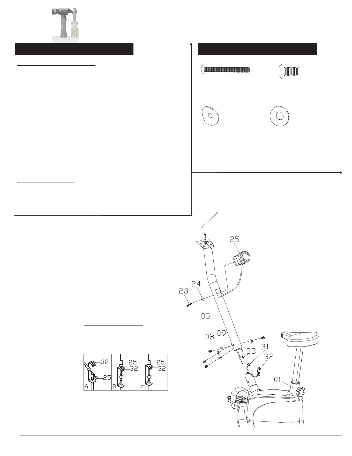
Page 7
TENSION WIRE ASSEMBLY
Insert the tip of the Tension Controller
(25) wire into the Tension Controller
Wire (32) head at an angle. Tilt the
Tension controller (25) wire into the
crevice and then pull upward.
Make sure this wire is exposed and
accessible before assembling the
Front Post (#05).
Assembly Instructions
55
40
1 2 3 4
55
40
1 2 3 4
STEP3:
As se mb l y St ep 3
BRU178/108
Tension Controller Assembly
Please remove the pre-assembled Screw (#23) and Arc Washer
(#24) from the Tension Controller (#25) and set them aside for
now. Next, insert the Tension Controller (#25) into the slot on the
Front Post (#05) as seen in illustration and secure using
the previously removed Screw (#23) and Arc Washer (#24).
Please make sure to tuck the wire of the Tension Controller (#25)
down through the Front Post (#05) and be careful not to pinch
the wire during assembly.
Wire Connection
Please remove the Bolts (#08) and Arc Washers (#09) pre-
assembled on the front protruding post of the Main Frame (#01)
and set them aside for now. With the help of an assistant, connect
the Monitor Wire (Middle) (#33) to the Monitor Wire (Lower) (#31).
Next, connect the Tension Controller Wire (#32) to the wire of the
Tension Controller (#25) at the bottom of the Front Post (#05).
Front Post Assembly
With the help of an assistant, insert the Front Post (#05) over the
front protruding post of the Main Frame (#01) and secure using
the previously removed four Bolts (#08) and four Arc Washers
(#09).
#23. Screw (M5x45 mm)
[1 Piece]
#24. Arc Washer (M5)
[1 Piece]
#08. Bolt (M8x15 mm)
[4 Pieces]
#09. Arc Washer (M8,φ20)
[4 Pieces]
Assembly Instructions
Page 8
Hardware Required
As sem b ly S te p 4
BRU178/108
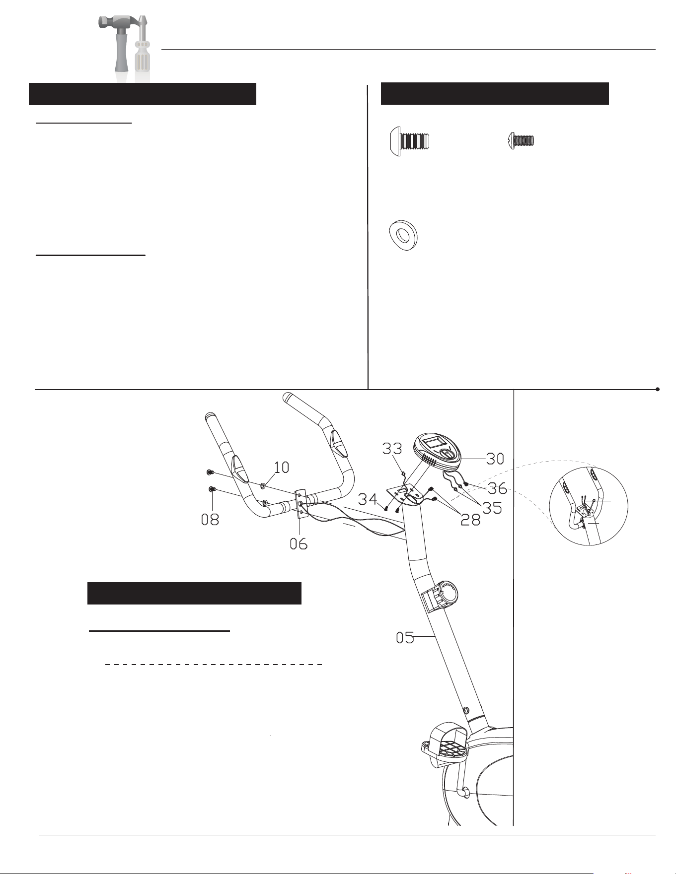
Monitor Assembly
Remove the Screws (#34) that are pre-assembled on the Monitor
(#30) and set them aside for now.
Connect the Monitor Wire (Middle) (#33) to the Monitor Wire
(Upper) (#36). Next, connect the Hand Pulse Sensors (#28)
each to one Hand Pulse Wire (#35). Tuck in the connected wires
into the hole on the Front Post (#05) to avoid pinching the wires.
Next, secure the Monitor (#30) to the Front Post (#05) using the
previously removed Screws (#34).
Handlebar Assembly
Remove the Bolts (#08) and Arc Washers (#10) that are pre-
assembled on the Front Post (#05) and set them aside for now.
Attach the Handlebar (#06) to the Front Post (#05) as shown
in the diagram below and secure using the previously removed
two Bolts (#08) and two Arc Washers (#10).
The assembly process is now complete. However, for your own safety,
please make sure to read this entire Owner’s Manual which includes
safety instructions and warnings, as well as any safety/warning labels
affixed to the product before use.
For your safety, please visually and functionally inspect and test the unit
after assembly is complete.
After complete assembly: If the computer
is not picking up your hand pulse signal
(or you are getting inaccurate readings),
Please refer to our “Troubleshooting”
section on Page 12 for other troubleshoot
issues.
HAND PULSE SIGNAL
Troubleshooting
#08. Bolt (M8x15 mm)
[2 Pieces]
#34. Screw (M5x10 mm)
[2 Pieces]
#10. Arc Washer (M8)
[2 Pieces]
Feed the wires of the
Hand Pulse Sensors(#28)
through the neck
of the Front Post (#05)
until they are exposed and
accessible from the opening
as illustrated.
28
05

Safety & Maintenance
• Make sure all nuts, bolts, and screws are tightened prior to use.
• Be sure that all adjustment locking devices and safety devices are properly engaged prior to use!
• Never over-tighten the above-mentioned devices and parts to avoid damage to the unit.
• Check for loose parts and components and make proper adjustments prior to use.
• Check to see if there are any tears or bends in the welding or metal prior to use. If tears or bends
are found, do NOT use the unit and contact our CUSTOMER SUPPORT.
• Extreme care must be taken to not allow your feet, fingers, hair, clothing, and/or any loose items to be
snagged into any portion of the bike when the unit is in motion. Failure to follow these instructions
could result in serious injury, including the loss of fingers.
• Always wait for the pedals and other moving parts (which can gain great momentum during riding) to
come to a complete stop before dismounting the unit to avoid serious injury.
• Do not use solvent cleaners. If you are in any doubt, do not use your cleansing product;
contact CUSTOMER SUPPORT.
SAFETY & WARNINGS
Ma in te na nc e & Car e
• For any replacement warning labels, please contact our CUSTOMER SUPPORT at (888) 266-6789
or (909) 598-9876, or mail in a written request to: Body Flex Sports, Inc. 21717 Ferrero Parkway,
Walnut, CA 91789. More detailed information about how to reach our CUSTOMER SUPPORT may
be found on Page 1 of the Owner’s Manual under the “CUSTOMER SUPPORT” section.
• The specific Parts on your unit which may see possible signs of wear after prolonged use are listed as
follows (please check these parts before each use):
Seat (#21); Tension Controller (#25); Right Pedal/Left Pedal (#15/16); Handlebar (#06).
• Please review all safety instructions and warnings in this entire Owner’s Manual, as well as any
safety/warning labels affixed to the product before use.
BRU178/108
Page 9
Computer Operation
B RU178/108
Page 10
FUNCTION MARK:
1. Lift off the battery cover and place two SIZE-AAA batteries into the
battery housing on back of monitor with the +/- sides installed correctly.
2. Please ensure batteries are correctly positioned and battery springs are in proper
contact with batteries.
3. Replace battery cover and ensure it is tightly closed.
4. Battery life is approx. 1 year under normal usage.
5. If the display is illegible or only partial segments appear, remove batteries and wait
15 seconds before reinstalling.
6. Removing the batteries will erase the computer memory.
*NOTE: Please refer to our “TROUBLESHOOTING” page in this manual if you have
any trouble with
the LCD Computer Monitor or Pulse/Recovery Functions.
FUNCTIONS AND OPERATIONS:
Mode or function: Explanation:
Auto On/Off & Auto As long as the machine is in motion, the monitor will
Start/Stop remain on. If the machine is not in use and/or not in
motion for over 4 minutes, the monitor will turn off and
reset all function values to zero.
Auto Scan
monitor will rotate through all 5 functions: Speed, Distance,
Time, Odometer & Calories. Each function will display for 6
seconds.
Speed Press the button until the ARROW points to “S” to display
the current speed.
Trip Distance Press the button until the ARROW points to “D” to display
the trip distanc
e you are traveling.
Elapsed Time Press the button until the ARROW points to “T” to display
the elapsed time.
Total Distance Press the button until the ARROW points to “O” to
(Odometer) display the total accumulated distance.
Press the button until the ARROW points to “A”, the
A: Auto Scan O: Odometer (Total Distance)
S: Current Speed C: Calories Burned
D: Distance Traveled : Pulse Rate
T: Elapsed Time
BATTERY INSTALLATION/REPLACEMENT:
0:00
TIME
ODOMETER
CALORIES
PULSE
DISTANCE
SPEED
SCAN
♥

Computer Operation
B RU178/108
Page 11
Current Speed
The maximum signal that can be detected is 1200
RPH
Trip Distance 0.1-999.9 Miles
Elapsed Time 0:00-99:59( Minute : Second )
Odometer 0.1-999.9 Miles
Calorie 0.1-999.9 K.cal
Pulse Rate 40-240 beats per minute
Controller 4 bit single chip microprocessor
Sensor No-contact magnetic type
Battery type 2 PCS of SIZE-AAA
Operating temperature
0℃ - +40℃ ( 32℉ - 104℉ )
Storage temperature -10℃ - +60℃ ( 14℉ - 140℉ )
Calories Press the button until the ARROW points to “C” to display
the calorie consumption/calories burned.
Pulse Rate Press the button until “ ” appears to show your heart rate
(Pulse) in beats per minute. Place the palms of your hands
and grip lightly on both the contact pads and the monitor will
display your heartbeat rate in beats per minute (BPM) on
the LCD display.
Reset Holding the button for 3 or more seconds will reset all
functional values to zero (except Odometer). The Odometer
will reset anytime the batteries are removed & replaced.
SPECIFICATIONS:
FUNCTION
Auto Scan Every 6 seconds
♥

Page 12
Troubleshooting
If the computer is not picking up your hand pulse signal (or you are getting
inaccurate readings), please adjust the following:
1. Slightly moisten/dampen the palms with water so the sensors can detect a
pulse signal.
2. Do not grip the sensors too tightly. Only moderate pressure need be applied.
Gripping the sensors too tightly restricts and seizes detection of your pulse.
3. Remove any rings or jewelry to prevent interference.
4. Check to ensure all pulse sensor wires are properly connected and are
not damaged.
You may need to refer to installation/assembly directions for the pulse sensor
wires in this manual.
If the computer is not displaying the CALORIES/DISTANCE/TIME/(ETC.) functions
(or you are getting inaccurate readings), please adjust the following:
1. Check to ensure all computer sensor wires are properly connected and are
not damaged.
You may need to refer to installation/assembly directions for the sensor wires
in this manual.
If the computer display is blank & not displaying any data (or does not appear to
power on), please adjust the following:
1. Check to ensure all sensor wires are all properly connected and are
not damaged.
2. Check to ensure the AC Adapter* or Batteries* are properly plugged in or
fully charged.
Troubleshoot Area
HAND PULSE SIGNAL
CALORIES/DISTANCE/
TIME/(ETC.)
COMPUTER Display
(AFTER COMPLETE ASSEMBLY)
Solution
*Please check your product manual to determine if your model uses either
1. an AC Adapter, or 2. Batteries to power your unit.
For your safety, please do not discard this Troubleshooting sheet or the Owner’s Manual,
and keep them in a place where you can easily access/refer to them at any time.
If you are still having any troubleshooting issues, please contact our Customer Support
for further assistance.
BRU178/108
WARNING: SERIOUS INJURIES AND EVEN DEATH CAN OCCUR IF THE PROPER SAFETY PRECAUTIONS ARE NOT FOLLOWED.
The diagram below highlights and reviews many of the important Safety and Warning labels also found
on the unit. Please ensure any user of the unit familiarizes themselves with these Safety and Warning
guidelines before use.
PLEASE KEEP THESE INSTRUCTIONS FOR FUTURE USE & REFERENCE.
DO NOT DISCARD.
Page 13
The use of this exercise equipment involves a RISK OF PHYSICAL INJURY as well as
property damage, which can be minimized by observing the following guidelines:
1. ALWAYS wear comfortable clothing
and shoes with good traction.
2. ALWAYS make sure all nuts and bolts
are secured before use. TIGHTEN
PEDAL HINGE BOLTS EVERY 30
DAYS.
3. STOP EXERCISING if you become
dizzy, nauseous, have irregular
heartbeats or breathing difficulties.
Contact your physician immediately.
4. ALWAYS keep a large mat under the
Equipment to
protect the floor or carpet.
5. ALWAYS use your Equipment in a
warm, dry, level well-lit and ventilated
indoor area.
7. ALWAYS keep your Equipment clean
and free of dust, moisture, debris and
loose objects.
8. NEVER use the Equipment if you are
injured or have a physical condition
that impairs your balance. DO NOT
exercise under the influence of
medication or alcohol.
9. NEVER allow small children or pets to
approach the Equipment. It is not a
toy.
10. NEVER u
se the Equipment if you
exceed its weight limit of 250 lbs.
11. NEVER use the Equipment if it does
not function properly.
6. ALWAYS keep body and clothing free
and clear of all moving parts.
W A R N I N G !
!
BRU178/108

Proof of purchase
Model Number BRU178/108
version:5-21-2012
BRU178/108