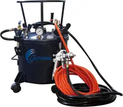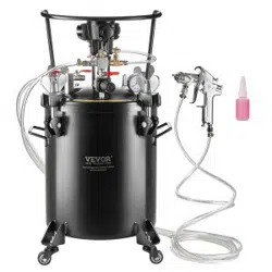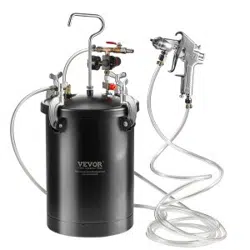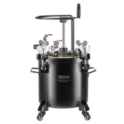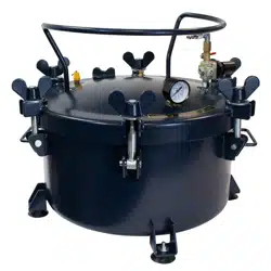

California Air Tools
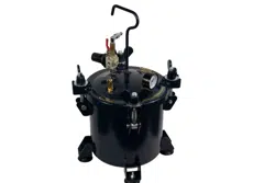
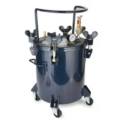
10 Gallon Casting Pressure Pot
Model No. 1810C
Technical Data
Item ……………………………………………………………………………………….…………1810C
Maximum pressure in the tank……………………………………………………………...….80 PSI
Working pressure in the tank…………………………………………………………………...60 PSI
Tank capacity………………………………………………………………………………40 I (10.0 gal)
Air Inlet………………………………………………………………………………….….1/4” Industrial
Interior………………………………………………………………. Diameter 17 3/4" & Depth 9 5/8"

Safety Guidelines- Definitions
NOTE!
Information that you should pay special attention to.
DANGER!
URGENT SAFTEY INFORMATION
A HAZARD THAT WILL CAUSE SERIOUS INJURY OR LOSS OF LIFE
CAUTION!
Information for preventing damage to equipment
WARNING!
IMPORTANT SAFETY INFORMATION
A HAZARD THAT MIGHT CAUSE SERIOUS INJURY OR LOSS OF LIFE
Important Safety Instructions
Save These Instructions
IMPROPER OPERATION OR MAINTENCE OF THIS PRODUCT COULD RESULT IN SERIOUS
INJURY AND PROPERTY DAMAG. READ AMD UNDERSTAND ALL WARNING AND OPERATING
INSTRUCTIONS BEFORE USING EQUIPMENT.
Over pressurization of Attachments
Hazard
What Could Happen
How To Prevent It
WARNING!
Explosion of objects
Attachments whose pressure
rating is lower than the adjusted
pressure in the tank could
explode, resulting in serious
injury or property damage.
Always make sure that
equipment connected to tank has
a higher-pressure rating than the
regulated air pressure tank
WARNING!
When performing maintenance disconnect the air line.
If for any reason it is required to replace any parts, it is recommended to replace part with original parts.
Never operate equipment while under the influence of alcohol or drugs. If you have signs of exhaustion
stop usage, it may cause an accident
Caution!
This pressure tank is not designed for highly abrasive or corrosive applications. If used with such
materials, frequent and thorough cleaning is advised to reduce excess wear and repair issues.

Assembly
Read the instructions carefully
Read instructions carefully before using this product. This equipment can be used to supply up to a
maximum of 80 (PSI). Operating PSI is 60 PSI. This equipment has an air regulator, pressure gauge,
safety valve and outlet. The tank has been coated to last.
.
Air Compressor
Use an air compressor that can produce at less 90 PSI.
1. WARNING! Ensure the air supply is clean and does not exceed 80psi while operating the tool.
Too high air pressure and unclean air will shorten the product life due to excessive wear, and may
be dangerous causing damage or personal injury.
2. Drain the air compressor air tank daily. Water in the air line will damage the tool.
3. Clean air inlet air filter weekly.
4. The air hose should not be longer than 50ft.
The minimum hose diameter should be 1/4” I.D. and fittings must have the same inside dimensions.
5. Keep hose away from heat, oil and sharp edges. Check hose for wear and make certain that all
connections are secure.
Assembly Instructions
1. Install the regulator assembly to the swivel adaptor on the tank lid.
Check the bottom of regulator for location of tank connection
2. Connect the air supply hose to the air inlet fitting on tank regulator. (Right or left optional)
Instructions for using Air Pressure Regulator
Purpose of Pressure Regulator
The pressure regulator regulates the amount of pressure applied in the tank.
Recommended Tank Pressure
For General Casting: Operating PSI should be 60 PSI in the tank.
Never exceed 80 PSI. This will activate the safety valve.
Important: Before turning on air pressure, screw out the regulator T-handle adjusting screw all the way
counter-clockwise, to shut off the air pressure. Turn on the air, and then adjust the regulator to the
required pressure. Operating PSI of 60 PSI. Do not use over 80 PSI in the tank.
Now adjust the regulator on the paint tank to obtain the desired air pressure for the material. The higher
above the paint tank you are spraying the more pressure you will need on the material. Normal operating
pressure on the paint tank is 60 PSI. Should you wish to reduce pressure, simply rotate T-handle
adjusting screw counter- clockwise until desired pressure setting is obtained. There is no need to trigger
the gun in order to bleed off excess paint pressure.
WARNING!
Do not use over 80 PSI in your tank.

WARNING!
Risk of tank explosion.
1. Modifications to the tank’s design or construction could weaken it. Assemble tank components in
accordance with the service instructions. Do not drill into tank, or weld attachments, or alter its
design in any manner.
2. Substitution of unauthorized non-standard components could weaken tank or cause component
failure. Use only those components furnished with the tank. Assembled in accordance with
instructions in the service literature.
3. Damage to the tank or its components could weaken the
tank. Never attempt to repair a damaged tank. Replace it with a new one.
4. Improper cleaning
or maintenance could block air passages to the safety valve, gauge or outlet, allowing pressure
to rise to dangerous levels and preventing the lowering of tank pressure. Following each use,
clean and dry tank and lid in accordance with maintenance instructions. Ensure ports to safety
valve, gauge and outlet are free of hardened paint or other materials which could prevent free
movement of air.
6. Tampering with the safety valve could allow tank pressure to rise to dangerous levels. Never
attempt to adjust safety valve to change its pressure setting or defeat its function in any way.
Operate the valve before each use to assure that it functions properly.
7. Removal of the lid while the tank is under pressure could result in the lid being propelled violently
8. from the tank. Before releasing clamp force to remove the lid, shut off the supply of tank inlet air
and turn the regulator knob counterclockwise to relieve air pressure. Check by pulling the safety
valve ring.
7. Use of reactive chemicals could attack the lid gasket and safety valve seal, allowing tank
pressure
to rise to dangerous levels. If this reaction occurs within an enclosed structure such as this tank,
it may cause explosion. Do not use reactive chemicals in your tank such as acids, caustic
solutions, or halogenated hydrocarbon solvents.
9. Over tightening clamps, causing them to weaken and fail could result in the lid being propelled
violently from the tank. If the lid gasket leaks, relieve the tank pressure and clean or replace the
gasket.
Operation
1. Open the compressor’s valve or turn it on
2. Turn the regulator knob clockwise to increase the pressure material. Turn it counterclockwise
to decrease pressure. The maximum tank pressure is 60 PSI.
3. The spray gun is adjustable by means of a valve adjustment or air regulator
4. Before using the gun make sure that all connections one tightened properly check that the air
gun works with air, also check that neither gun nor hose have dirt or impurities
5. Connect the materials hose to coupling A and the air hose to coupling B.
6. Adjust the required size range; completely closing the lead screw, which is located on the
side of the gun, and opening it slowly until it reaches the desired array pattern.
7. Adjust the amount of material applied by completely closing the lead screw, which is located
in the rear, and opening it slowly until it reaches the desired amount of material.
8. Always paint at a uniform distance (15 t0 30 cm) and parallel to the surface you are applying
the material to.

Maintenance and Storage
1. Close the air flow to the equipment.
2. Release all air pressure in the tank by pulling the safety valve ring until the pressure
subsides.
3. Rotate the tank regulator handle “T” counterclockwise until you do not feel any tension in the
spring.
4. Loosen the metal screws, remove the wing nuts, and open the lid to one side.
5. Loosen the metal rings on the gun nozzle about three turns.
6. Open the air supply.
7. Place a cloth or rag onto the mouthpiece like a receptacle and cover, and then pull the trigger.
This action will force the remaining material in the hose to go back into the tank.
8. Empty and clean the tank and parts that have been in contact with the material by using a
solvent recommended by the manufacturer.
9. Pour some solvent into the tank.
10. Place the lid and the wing nuts and tighten the thumbscrews.
Cleaning Instructions
WARNING!
Always shut off air pressure at the source and bleed off all pressure in the Tank by gently pulling
the safety valve ring before loosening thumb screw and clamps remove lid.
Turn off the main air supply to the tank. Remove all pressure from the tank by pulling the ring on the
safety valve until the pressure bleeds down. Turn the T-handle adjusting screw on the regulator
counter-clockwise until no spring tension is felt. Loosen thumb screws, tip clamps back and tip the tank lid
to one side. Empty and clean tank and parts which come in contact with the material. Use a suitable
solvent. Pour solvent into the tank. Replace the lid and tighten the thumb screws and clamps and spray
until clean appears.

Trouble Shooting
WARNING!
If any of the following symptoms appears during your operating, stop using the tool immediately, or
serious personal injury could result.
Only a qualified persons or an authorized service center can perform repairs or replacement of tool.
Disconnect tool from air supply before attempting repair or adjustment. When replacing O-rings or
Cylinder, lubricate with air tool oil before assembly.
PROBLEMS
POSSIBLE CAUSES
CORRECTION
Air escaping from port on
regulator cap
Broken or damaged
diaphragm in regulator.
Replace regulator
Pressure dropping slowly
on gauge.
Dirty or work valve seat in
regulator.
Replace regulator
Air leak at the lid gasket.
Defective lid gasket.
Thumb screw not tight.
Replace lid gasket.
Tighten thumb screws.
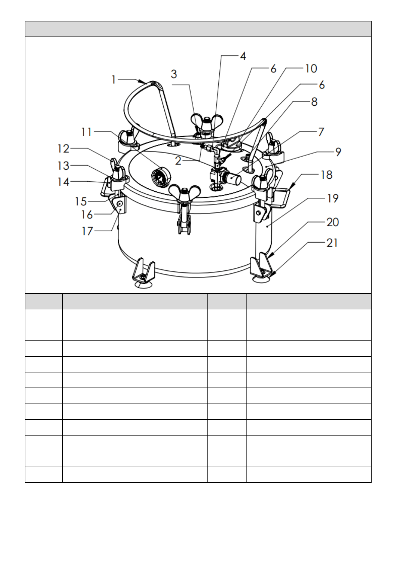
EXPLOSIVE DRAWING OF CAT-1810C
NO.
DESCRIPTION
NO.
DESCRIPTION
1
LID HANDLE BAR
12
M16 WING NUT
2
INLET VALVE
13
M16 WASHER
3
SAFETY VALVE
14
LID SIDE BRACKET
4
ELBOW CONNECTOR
15
M16 BOLT
5
S14 CONNECTOR
16
PIN φ12
6
G1/4 BALL VALVE
17
TANK SIDE BRACKET
7
PRESSURE REGULATOR KIT
18
TANK SIDE HANDLEBAR
8
DISCHARGE VALVE
19
TANK
9
TANK LID
20
FOOT BRACKET
10
LARGE BUNG
21
CUSHION FOOT
11
PRESSURE GAUGE

Limited Warranty
This Warranty is Limited to CALIFORNIA AIR TOOLS and SPRAYIT Products.
Limited Warranty: 1 Year
CALIFORNIA AIR TOOLS, Inc. will repair or replace, free of charge, to the original retail
customer whom purchased a CALIFORNIA AIR TOOLS or SPRAYIT product from an authorized
dealer, distributor or distributor’s dealer.
This warranty does not transfer to subsequent owners.
CALIFORNIA AIR TOOLS, Inc. will repair or replace, at its option, any parts that are proven by an
authorized service center to be defective in material or workmanship under normal use
during the applicable warranty time period as stated above.
This limited warranty covers the cost of the replacement parts and labor for all defects when
installed by an authorized service center.
Transportation charges are the responsibility of the customer.
Any part replaced under warranty becomes the property of CALIFORNIA AIR TOOL, Inc.
All parts replaced under warranty will be considered as part of the original product, and any
warranty on those parts will expire coincident with the original product warranty.
The limited warranty period begins on the date of the retail purchase by the original
purchaser.
CALIFORNIA AIR TOOL, Inc.
8560 Siempre Viva Road
San Diego, California 92154
Tel: (866) 409-4581
Fax (619) 424-8697
www.CALIFORNIAAIRTOOLS.com