FeelElec
FY8300S Series Fully Numerical Control
Three +Four Channel Function/Arbitrary Waveform
Generator
User’s Manual
Rev1.0 May,2019

FeelElec
FY8300S Series User’s Manual I
Guaranty and Declaration
Copyright
© 2019 FeelElec Technology Co. Ltd. All Rights Reserved.
Declaration
● FeelElec reserves the right to modify or change parts of or all the
specifications and pricing policies at company’s sole decision.
● Information in this publication replaces all previously corresponding material.
● FeelElec shall not be liable for losses caused by either incidental or
consequential in connection with the furnishing, use or performance of this
manual as well as any information contained.
●Any part of this document is forbidden to be copied or photocopied or
rearranged without prior written approval of FeelElec.
Contact Us
If you have any problem or requirement when using our products or this
manual, please contact FeelElec.
Tel: 0086 371 68997005 E-mail:FeelElec@126.com
Website:www.feelelec.com
FeelElec
II FY8300S Series User’s Manual
Contents
Guaranty and Declaration ................................................................................... I
Product Introduction .......................................................................................... 3
Quick Start ........................................................................................................... 6
General Inspection.......................................................................................... 6
Front Panel Overview ..................................................................................... 7
Back Panel Overview .................................................................................... 10
Power On and Inspection ............................................................................. 12
User Interface ............................................................................................... 13
Appearance and Dimensions ........................................................................ 16
Front Panel Operations .................................................................................... 17
Waveform Output .......................................................................................... 17
Select Output Channel .............................................................................................. 17
Select Waveform ....................................................................................................... 18
Set Frequency ........................................................................................................... 20
Set Amplitude ............................................................................................................ 21
Set Offset ................................................................................................................... 22
Set Duty Cycle (Rectangle)&Set pulse wave pulse width (Adj-Pulse) .................. 23
Set Phase .................................................................................................................. 24
Enable Output ........................................................................................................... 25
Example:Output Sine Waveform ............................................................................ 26
Burst .......................................................................................................... 28
Modulation Function .................................................................................. 28
Frequency Meter/Counter ............................................................................. 31
Enable the Counter ................................................................................................... 31
Set the Counter ......................................................................................................... 32
Sweep ........................................................................................................... 33
Sweep Object ............................................................................................................ 33
Sweep Start Position ................................................................................................. 34
Sweep End Position .................................................................................................. 35
VCO (Voltage Control Output) Sweep ...................................................................... 37
Sweep Type ............................................................................................................... 38
Enable Sweep Function ............................................................................................ 39
System Configuration and Auxiliary Functions .............................................. 40
Save and Load .......................................................................................................... 41
Configuration ............................................................................................................. 42
Uplink ......................................................................................................................... 43
Synchronization ......................................................................................................... 44
Troubleshooting ................................................................................................ 45
Technical Specification .................................................................................... 46
Appendix ........................................................................................................... 50
FeelElec
FY8300 Series User’s Manual
3
Product Introduction
This manual applies to each model of FY8300S series Function/Arbitrary
Waveform Signal Generator. The last three characters of the model indicate the
up limit output of Sine Wave (MHz). For example, the “60M” of the Model Number
“FY8300S-60M” indicates the Sine wave maximum output frequency is up to
60MHz.
FY8300S series Three-channel Function / Arbitrary waveform generator is a
set of Function Signal Generator, Arbitrary Waveform Generator, Pulse Generator,
Analog / Digital modulator, Four-Channel TTL Signal Generator, VCO, Sweep,
Counters and Frequency Meter and other functions in a high Performance,
cost-effective, multi-function signal generator. Abundant shortcut keys and
graphical user interface simplifies every operation. Users do not have to spend a
lot of time to learn and familiar with the operation of the instrument, you can be
skilled use. For education, research and development, production, testing,
maintenance and other industries to provide a new choice.
The instrument adopt the Direct Digital Synthesizer (DDS) technology
and provide stable, precise, pure and low distortion signals. Surface mounting
technology improves interference immunity and operational life span. Can output
up to 97 groups of functions / arbitrary waveform, contains 33 groups of preset
waveforms and 64 groups of user-defined waveforms. Preset waveforms: Sine,
Square, Rectangle (Duty Cycle adjustable), Pulse (Pulse width and cycle time
can be set accurately), Triangle/Ramp, CMOS(0~12V), Four channels TTL,
Exponential Rise, Exponential Fall, Noise, ECG, DC etc.
FeelElec
4 FY8300S Series User’s Manual
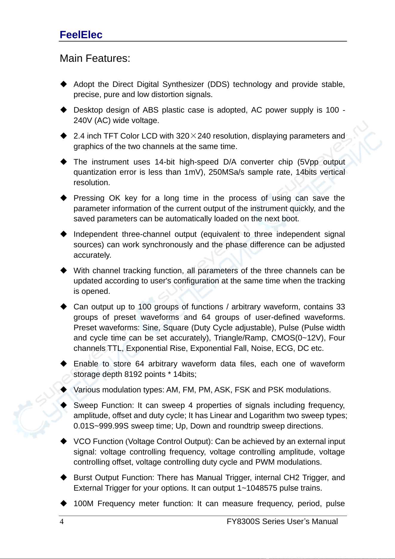
Main Features:
◆ Adopt the Direct Digital Synthesizer (DDS) technology and provide stable,
precise, pure and low distortion signals.
◆ Desktop design of ABS plastic case is adopted, AC power supply is 100 -
240V (AC) wide voltage.
◆ 2.4 inch TFT Color LCD with 320×240 resolution, displaying parameters and
graphics of the two channels at the same time.
◆ The instrument uses 14-bit high-speed D/A converter chip (5Vpp output
quantization error is less than 1mV), 250MSa/s sample rate, 14bits vertical
resolution.
◆ Pressing OK key for a long time in the process of using can save the
parameter information of the current output of the instrument quickly, and the
saved parameters can be automatically loaded on the next boot.
◆ Independent three-channel output (equivalent to three independent signal
sources) can work synchronously and the phase difference can be adjusted
accurately.
◆ With channel tracking function, all parameters of the three channels can be
updated according to user's configuration at the same time when the tracking
is opened.
◆ Can output up to 100 groups of functions / arbitrary waveform, contains 33
groups of preset waveforms and 64 groups of user-defined waveforms.
Preset waveforms: Sine, Square (Duty Cycle adjustable), Pulse (Pulse width
and cycle time can be set accurately), Triangle/Ramp, CMOS(0~12V), Four
channels TTL, Exponential Rise, Exponential Fall, Noise, ECG, DC etc.
◆ Enable to store 64 arbitrary waveform data files, each one of waveform
storage depth 8192 points * 14bits;
◆ Various modulation types: AM, FM, PM, ASK, FSK and PSK modulations.
◆ Sweep Function: It can sweep 4 properties of signals including frequency,
amplitude, offset and duty cycle; It has Linear and Logarithm two sweep types;
0.01S~999.99S sweep time; Up, Down and roundtrip sweep directions.
◆ VCO Function (Voltage Control Output): Can be achieved by an external input
signal: voltage controlling frequency, voltage controlling amplitude, voltage
controlling offset, voltage controlling duty cycle and PWM modulations.
◆ Burst Output Function: There has Manual Trigger, internal CH2 Trigger, and
External Trigger for your options. It can output 1~1048575 pulse trains.
◆ 100M Frequency meter function: It can measure frequency, period, pulse
FeelElec
FY8300 Series User’s Manual
5
width and duty cycle. Max. frequency workable is 100MHz and Min.
frequency workable is 0.01 Hz.
◆ Channel SYNC Function: Support waveform copy and state copy between
channels.
◆ Support two or more signal generators connected to achieve multi-channel
output, the maximum support 16-channel synchronous output, the phase
between each channel can be adjusted.
◆ Precisely adjust the phases of the three channels, Precision can be 0.01°.
◆ Minimum amplitude resolution can be up to 1 mV. Amplitude range is
0~20Vpp.
◆ Duty-cycle of each channel can be adjusted independently0.01%-99.99%,
the adjusting resolution is 0.01%.
◆ -12V~+12V DC Offset function. Resolution 0.001V.
◆ Save function: It can save 12 sets user-set parameters and can be loaded at
any time.
◆ Communicating function: All functions can be controlled by PC program and
the communication protocol is open for secondary development.
◆ Output short-circuit protection: All channels can work more than 60 seconds
when the load is short-circuited.
◆ Provide powerful waveform editing PC software. Users can download
arbitrary waveform to this instrument after edit through PC program which is
included in user CD.
◆ Adopt ABS plastic shell with table type design. Use 100-240V (AC) wide
range voltage power supply.
◆ Can choose our FYA2000S series or FPA2000 series power amplifier to
output 20W~100W signal in DC-10MHz width without any distortion.

FeelElec
6 FY8300S Series User’s Manual
Quick Start
General Inspection
Please follow the items below when you receive a new FY8300S series
Function/Arbitrary Waveform Generator.
1. Inspect the shipping container for damage
Keep the damaged shipping container or cushioning material until the
contents of the shipment have been checked for completeness and the
instrument has passed both electrical and mechanical tests. The consigner or
carrier shall be liable for the damage to instrument resulting from shipment.
2. Inspect the instrument
In case of any damage, or defect, or failure, notify your FeelElec sales
representative.
3. Check the accessories
Please check the accessories according to the Appendix C ( packing lists). If
the accessories are incomplete or damaged, please contact your FeelElec sales
representative.
FeelElec
FY8300 Series User’s Manual
7
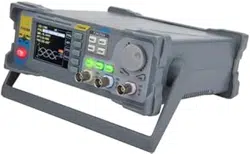
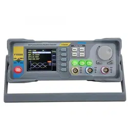
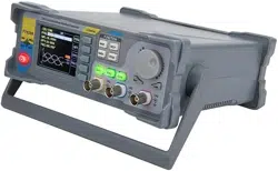
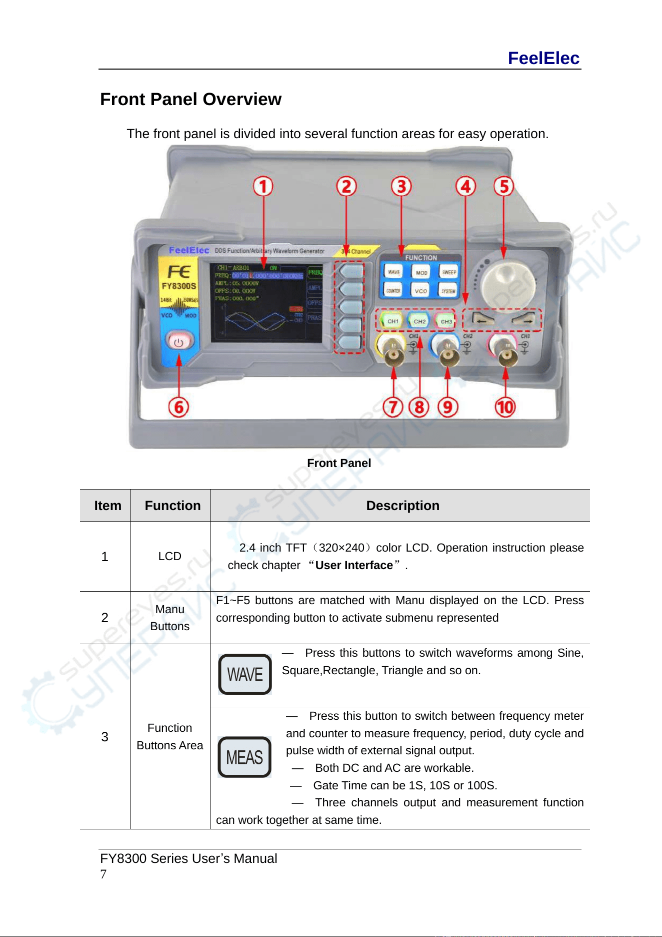
Front Panel Overview
The front panel is divided into several function areas for easy operation.
Front Panel
Item
Function
Description
1
LCD
2.4 inch TFT(320×240)color LCD. Operation instruction please
check chapter “User Interface”.
2
Manu
Buttons
F1~F5 buttons are matched with Manu displayed on the LCD. Press
corresponding button to activate submenu represented
3
Function
Buttons Area
— Press this buttons to switch waveforms among Sine,
Square,Rectangle, Triangle and so on.
— Press this button to switch between frequency meter
and counter to measure frequency, period, duty cycle and
pulse width of external signal output.
— Both DC and AC are workable.
— Gate Time can be 1S, 10S or 100S.
— Three channels output and measurement function
can work together at same time.
FeelElec
8 FY8300S Series User’s Manual
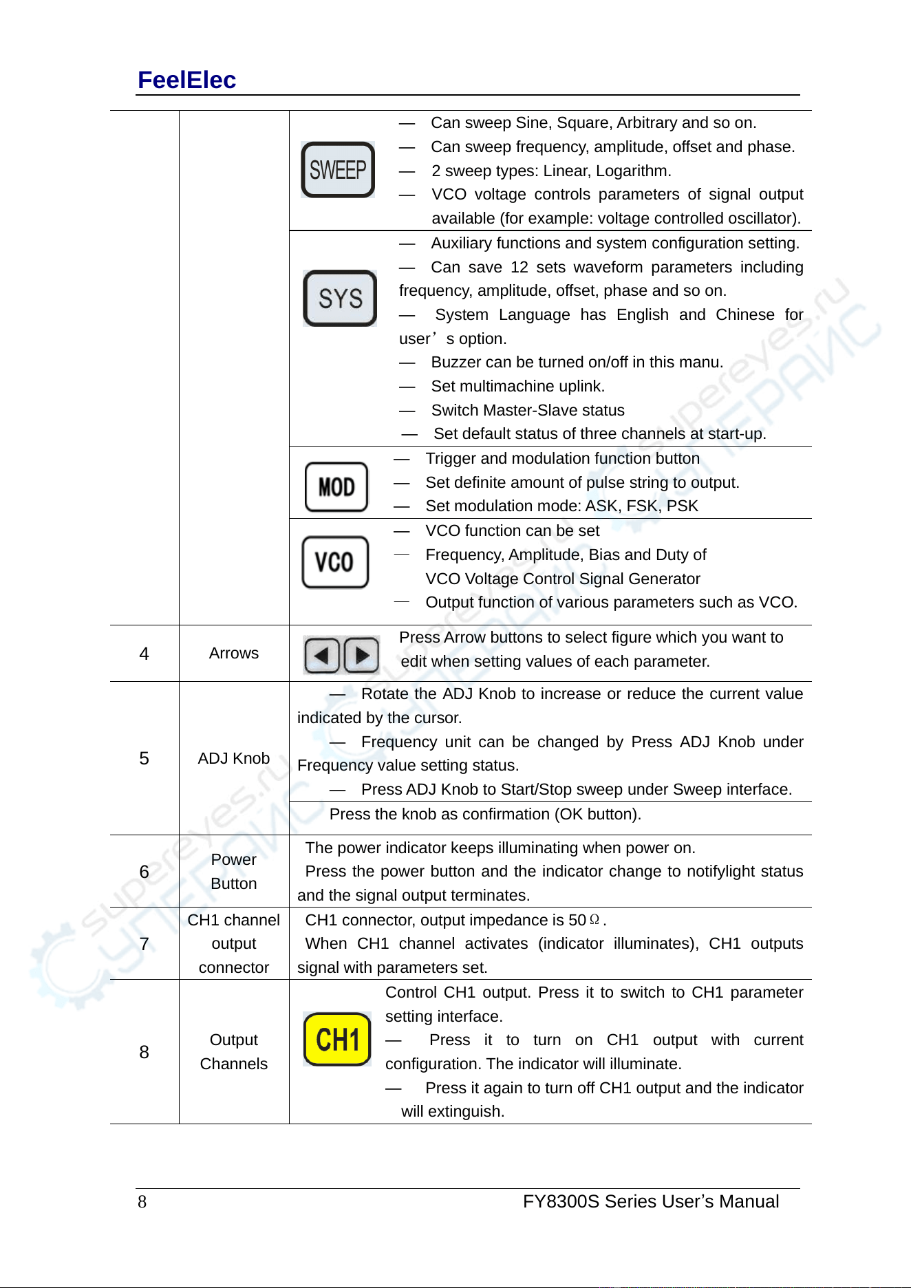
— Can sweep Sine, Square, Arbitrary and so on.
— Can sweep frequency, amplitude, offset and phase.
— 2 sweep types: Linear, Logarithm.
— VCO voltage controls parameters of signal output
available (for example: voltage controlled oscillator).
— Auxiliary functions and system configuration setting.
— Can save 12 sets waveform parameters including
frequency, amplitude, offset, phase and so on.
— System Language has English and Chinese for
user’s option.
— Buzzer can be turned on/off in this manu.
— Set multimachine uplink.
— Switch Master-Slave status
— Set default status of three channels at start-up.
— Trigger and modulation function button
— Set definite amount of pulse string to output.
— Set modulation mode: ASK, FSK, PSK
— VCO function can be set
— Frequency, Amplitude, Bias and Duty of
VCO Voltage Control Signal Generator
— Output function of various parameters such as VCO.
4
Arrows
Press Arrow buttons to select figure which you want to
edit when setting values of each parameter.
5
ADJ Knob
— Rotate the ADJ Knob to increase or reduce the current value
indicated by the cursor.
— Frequency unit can be changed by Press ADJ Knob under
Frequency value setting status.
— Press ADJ Knob to Start/Stop sweep under Sweep interface.
Press the knob as confirmation (OK button).
6
Power
Button
The power indicator keeps illuminating when power on.
Press the power button and the indicator change to notifylight status
and the signal output terminates.
7
CH1 channel
output
connector
CH1 connector, output impedance is 50Ω.
When CH1 channel activates (indicator illuminates), CH1 outputs
signal with parameters set.
8
Output
Channels
Control CH1 output. Press it to switch to CH1 parameter
setting interface.
— Press it to turn on CH1 output with current
configuration. The indicator will illuminate.
— Press it again to turn off CH1 output and the indicator
will extinguish.
FeelElec
FY8300 Series User’s Manual
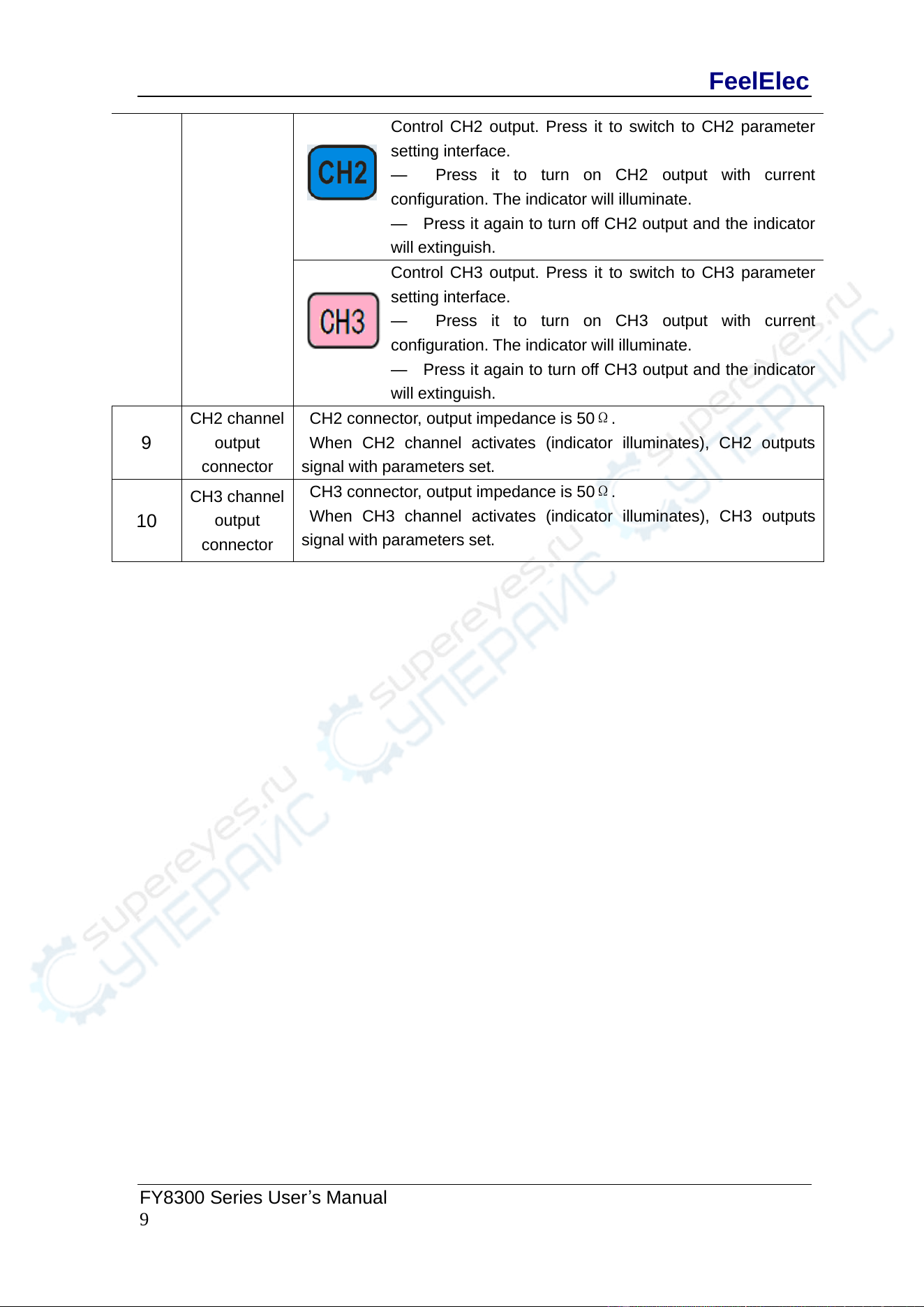
9
Control CH2 output. Press it to switch to CH2 parameter
setting interface.
— Press it to turn on CH2 output with current
configuration. The indicator will illuminate.
— Press it again to turn off CH2 output and the indicator
will extinguish.
Control CH3 output. Press it to switch to CH3 parameter
setting interface.
— Press it to turn on CH3 output with current
configuration. The indicator will illuminate.
— Press it again to turn off CH3 output and the indicator
will extinguish.
9
CH2 channel
output
connector
CH2 connector, output impedance is 50Ω.
When CH2 channel activates (indicator illuminates), CH2 outputs
signal with parameters set.
10
CH3 channel
output
connector
CH3 connector, output impedance is 50Ω.
When CH3 channel activates (indicator illuminates), CH3 outputs
signal with parameters set.
FeelElec
10 FY8300S Series User’s Manual
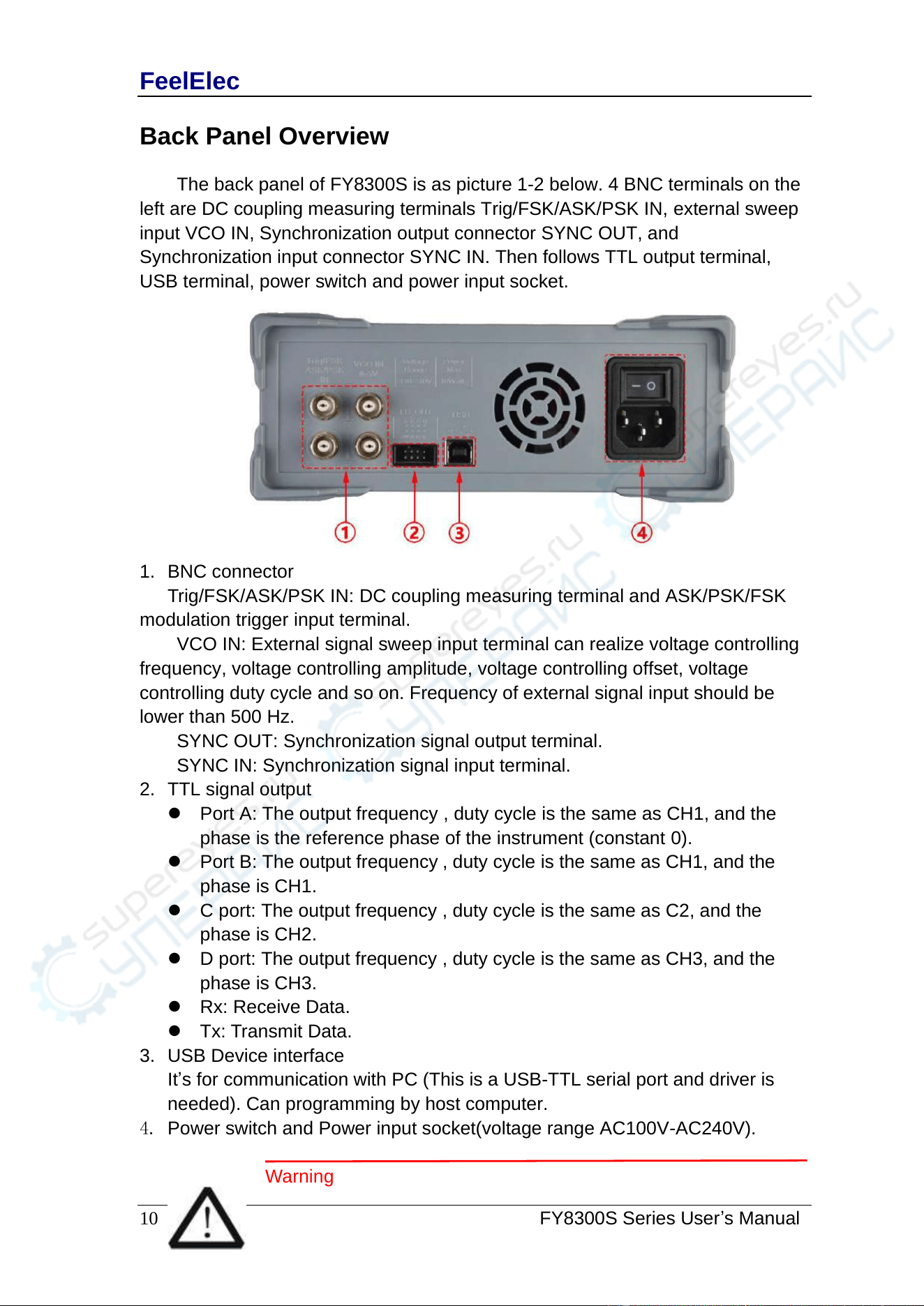
Back Panel Overview
The back panel of FY8300S is as picture 1-2 below. 4 BNC terminals on the
left are DC coupling measuring terminals Trig/FSK/ASK/PSK IN, external sweep
input VCO IN, Synchronization output connector SYNC OUT, and
Synchronization input connector SYNC IN. Then follows TTL output terminal,
USB terminal, power switch and power input socket.
1. BNC connector
Trig/FSK/ASK/PSK IN: DC coupling measuring terminal and ASK/PSK/FSK
modulation trigger input terminal.
VCO IN: External signal sweep input terminal can realize voltage controlling
frequency, voltage controlling amplitude, voltage controlling offset, voltage
controlling duty cycle and so on. Frequency of external signal input should be
lower than 500 Hz.
SYNC OUT: Synchronization signal output terminal.
SYNC IN: Synchronization signal input terminal.
2. TTL signal output
⚫ Port A: The output frequency , duty cycle is the same as CH1, and the
phase is the reference phase of the instrument (constant 0).
⚫ Port B: The output frequency , duty cycle is the same as CH1, and the
phase is CH1.
⚫ C port: The output frequency , duty cycle is the same as C2, and the
phase is CH2.
⚫ D port: The output frequency , duty cycle is the same as CH3, and the
phase is CH3.
⚫ Rx: Receive Data.
⚫ Tx: Transmit Data.
3. USB Device interface
It’s for communication with PC (This is a USB-TTL serial port and driver is
needed). Can programming by host computer.
4. Power switch and Power input socket(voltage range AC100V-AC240V).
Warning
FeelElec
FY8300 Series User’s Manual
1 1
T o avoid instrument damage, voltage of signal input from
EXT.IN CANNOT exceed ±20Vac+dc.V o ltage of signal input from
Trig/FSK/ASK/PSK IN CANNOT exceed DC5V.
Note
To ensure the normal work, please use 100-240V AC power
supply.
FeelElec
12 FY8300S Series User’s Manual
Power On and Inspection
Connect to Power
Please connect the generator to AC power supply using the Power cable
supplied in the accessories. The power supply use 100-240V AC power. The
power of this instrument is less than 10W.
Power On
Turn on the power switch after the power cord is connected. The generator
will execute self-inspection. The LCD will show welcome interface after the
inspection is over. If the generator cannot work normally, please check the
Chapter “Troubleshooting” for solution.
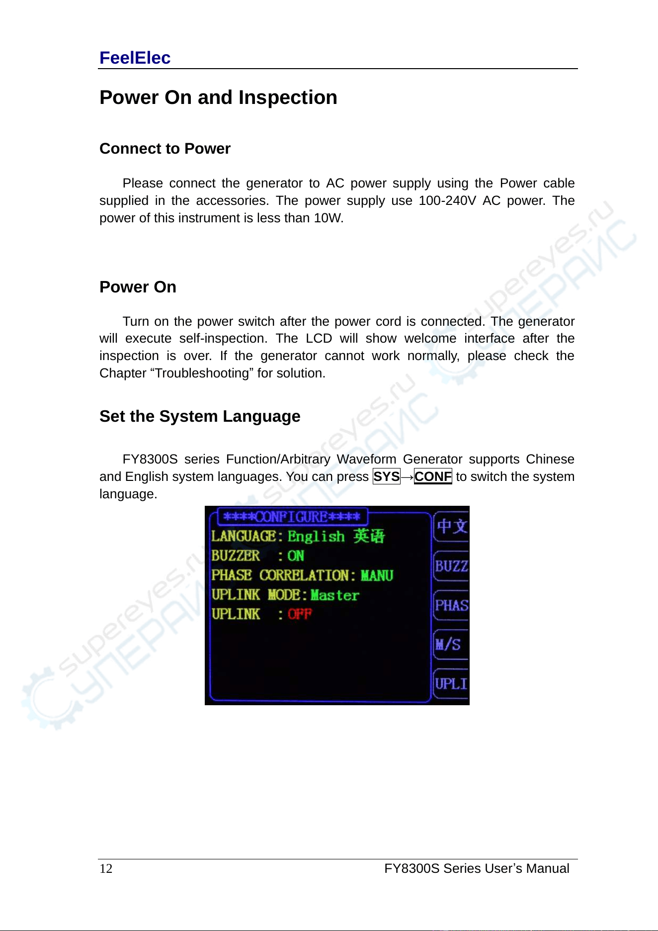
Set the System Language
FY8300S series Function/Arbitrary Waveform Generator supports Chinese
and English system languages. You can press SYS→CONF to switch the system
language.
FeelElec
FY8300 Series User’s Manual
13
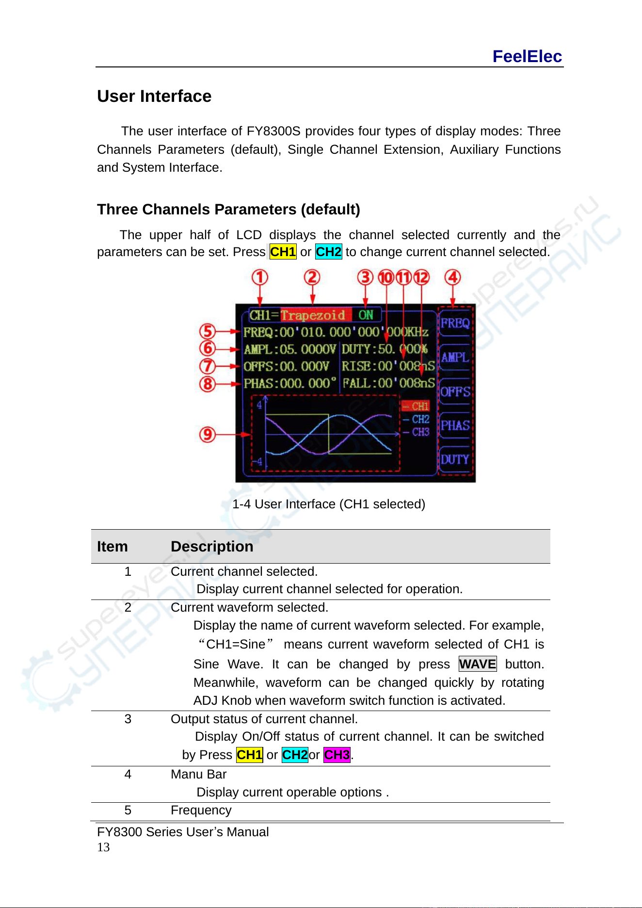
User Interface
The user interface of FY8300S provides four types of display modes: Three
Channels Parameters (default), Single Channel Extension, Auxiliary Functions
and System Interface.
Three Channels Parameters (default)
The upper half of LCD displays the channel selected currently and the
parameters can be set. Press CH1 or CH2 to change current channel selected.
1-4 User Interface (CH1 selected)
Item
Description
1
Current channel selected.
Display current channel selected for operation.
2
Current waveform selected.
Display the name of current waveform selected. For example,
“CH1=Sine” means current waveform selected of CH1 is
Sine Wave. It can be changed by press WAVE button.
Meanwhile, waveform can be changed quickly by rotating
ADJ Knob when waveform switch function is activated.
3
Output status of current channel.
Display On/Off status of current channel. It can be switched
by Press CH1 or CH2or CH3.
4
Manu Bar
Display current operable options .
5
Frequency
FeelElec
14 FY8300S Series User’s Manual
Display frequency value of current channel. Press FREQ
button to highlight it and use ADJ Knob and Arrows to change
the value.
6
Amplitude
Display amplitude value of current channel. Press AMPL
button to highlight it and use ADJ Knob and Arrows to change
the value.
7
Offset
Display DC Offset value of current channel. Press OFFS
button to highlight it and use ADJ Knob and Arrows to change
the value.
8
Phase
Display Phase value of current channel. Press PHAS to
highlight it and use ADJ Knob and Arrows to change the
value.
9
Waveform
Display diagram of current waveform(Including Arbitrary).
Yellow indicates CH1 and blue indicates CH2 and Violet
indicates CH3.
The amplitude, offset and phase information of the output
signals of CH1, CH2 and CH3 channels will be reflected in the
waveform display window. The waveform amplitude displayed
in the window will automatically switch gears according to the
actual amplitude of the three channels.
10
Duty Cycle
Display Duty Cycle value of current channel. Press DUTY
button to highlight it and use ADJ Knob and Arrows to change
the value.
Note: Duty cycle parameters are only valid for rectangular
wave, trapezoidal wave and CMOS wave.
11
RISE EDGE.
Show the rising edge time of the currently selected channel
waveform. Repeatedly press the up button, the menu bar will
switch in the duty/up/down function. When the "up" display
value is highlighted, the parameter will be changed by the
direction key and knob.
Note: Rising edge parameters are only valid for trapezoidal
waves.
12
DESCENDING EDGE.
Show the time of the current selected channel waveform drop
edge. Repeatedly press the corresponding drop button, the

FeelElec
FY8300 Series User’s Manual
15
menu bar will switch in the duty/up/down function. When the
"drop" display value is highlighted, the parameter will be
changed by the direction key and knob.
Note: The descent edge parameters are only valid for
trapezoidal waves.
FeelElec
16 FY8300S Series User’s Manual
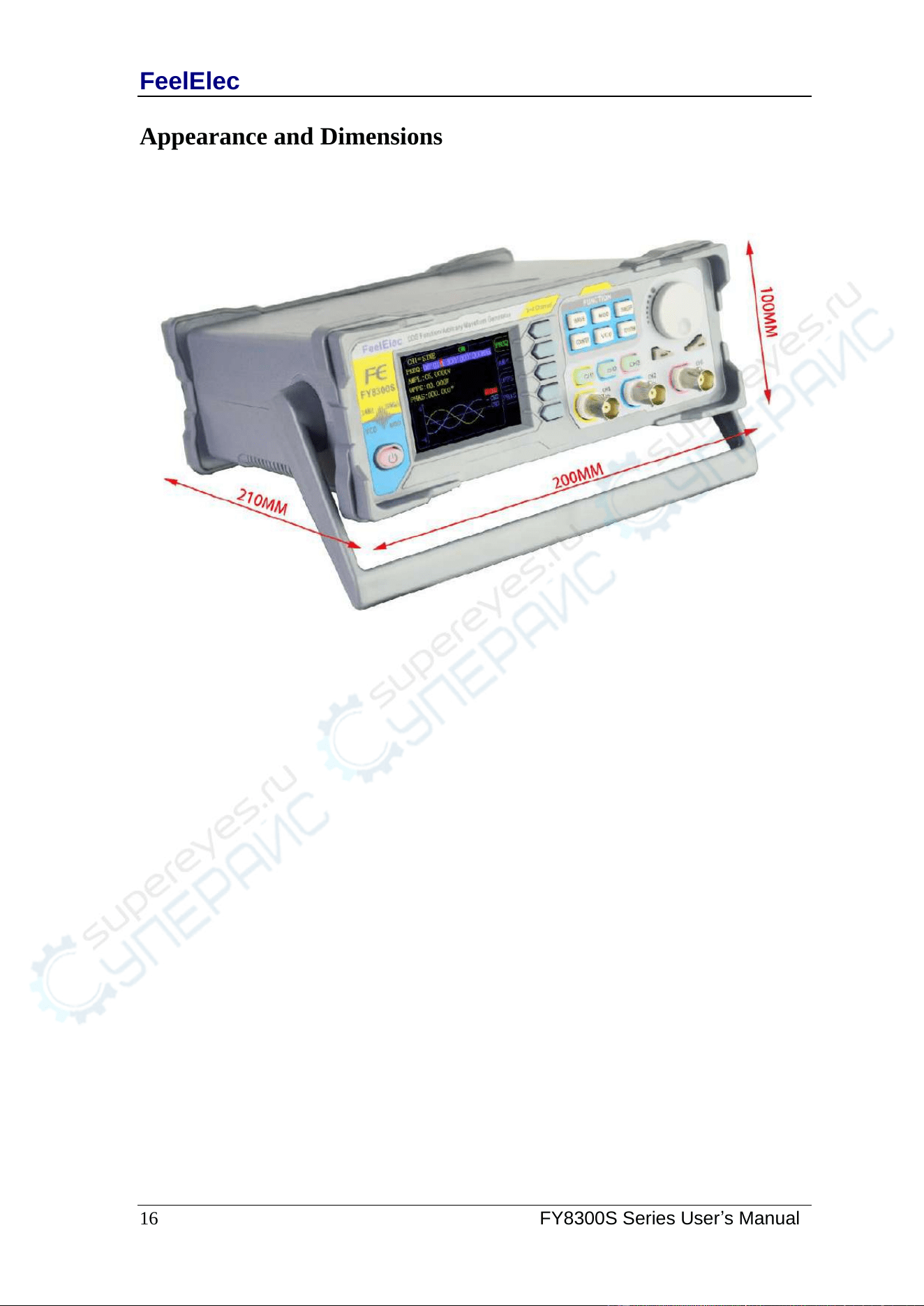
Appearance and Dimensions
FeelElec
FY8300 Series User’s Manual
17
Front Panel Operations
Waveform Output
FY8300S series can output waveforms (Sine, Square, Triangle/Ramp, Pulse
and Noise etc.) from Three channels at the same time. The default configuration
of the three channels is a sinusoidal wave with a frequency of 10 kHz, an
amplitude of 5 Vpp and a phase difference of 120 degrees. Three channels use
default setting saved at Position 1 when power on. Users can configure the
instrument to output various waveforms.
Select Output Channel
CH1 、CH2 and CH3buttons are used to change current channel selected.
At start-up, CH1 is displayed on the top with yellow color and CH2 is displayed on
the bottom with blue color. Press CH1 、CH2 and CH3to select channel needed.
When selecting CH2 as output channel, CH2 parameters displays on the top for
configuration.
KEY POINT:
CH1、CH2 and CH3 can not be selected at the same time. Users can first
select CH1 and then select CH2 or CH3 after configuring the waveform and
parameters of CH1. If you need to change the parameters of three channel at
same time, please refer to Chapter “Synchronization”.
FeelElec
18 FY8300S Series User’s Manual
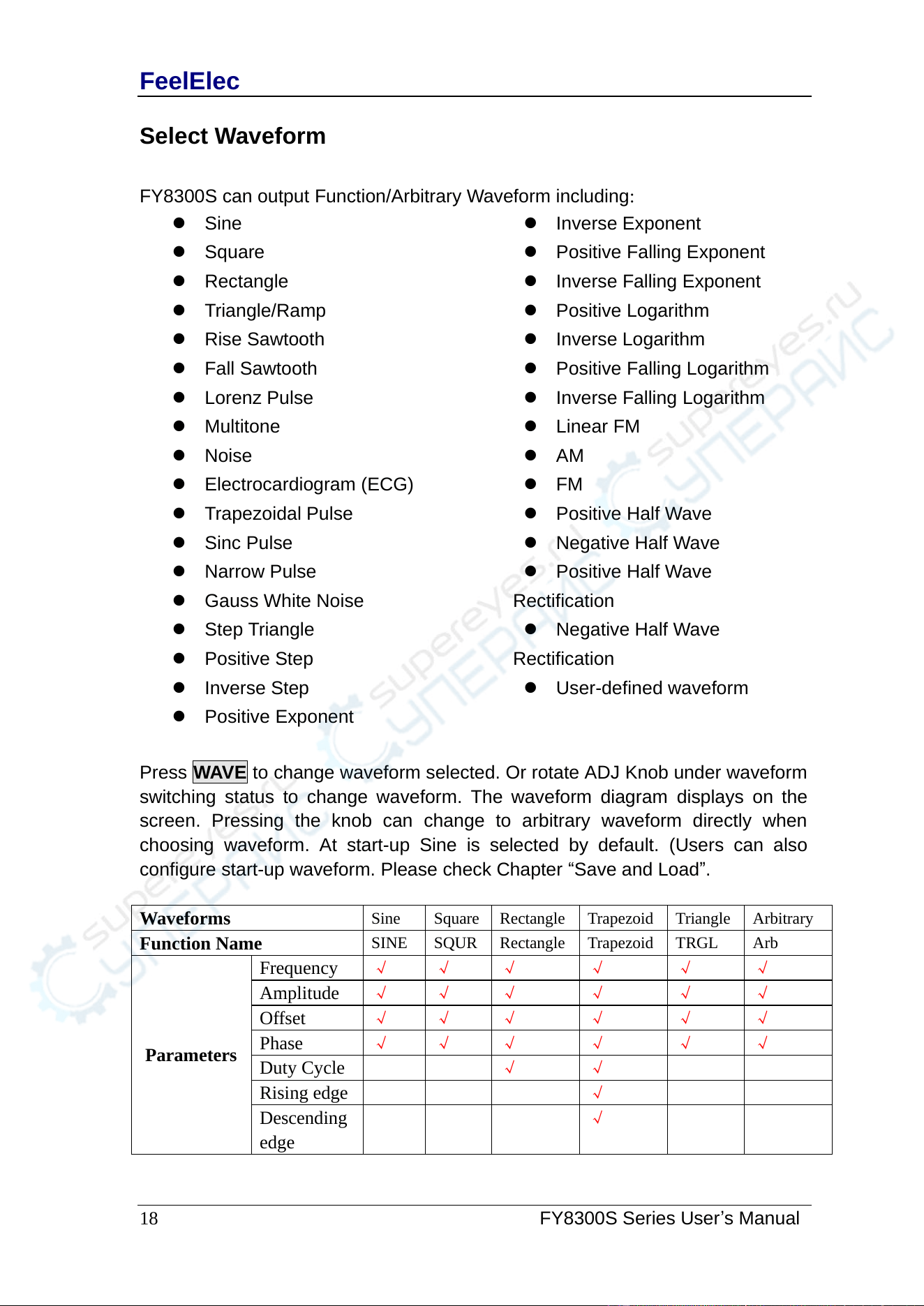
Select Waveform
FY8300S can output Function/Arbitrary Waveform including:
⚫ Sine
⚫ Square
⚫ Rectangle
⚫ Triangle/Ramp
⚫ Rise Sawtooth
⚫ Fall Sawtooth
⚫ Lorenz Pulse
⚫ Multitone
⚫ Noise
⚫ Electrocardiogram (ECG)
⚫ Trapezoidal Pulse
⚫ Sinc Pulse
⚫ Narrow Pulse
⚫ Gauss White Noise
⚫ Step Triangle
⚫ Positive Step
⚫ Inverse Step
⚫ Positive Exponent
⚫ Inverse Exponent
⚫ Positive Falling Exponent
⚫ Inverse Falling Exponent
⚫ Positive Logarithm
⚫ Inverse Logarithm
⚫ Positive Falling Logarithm
⚫ Inverse Falling Logarithm
⚫ Linear FM
⚫ AM
⚫ FM
⚫ Positive Half Wave
⚫ Negative Half Wave
⚫ Positive Half Wave
Rectification
⚫ Negative Half Wave
Rectification
⚫ User-defined waveform
Press WAVE to change waveform selected. Or rotate ADJ Knob under waveform
switching status to change waveform. The waveform diagram displays on the
screen. Pressing the knob can change to arbitrary waveform directly when
choosing waveform. At start-up Sine is selected by default. (Users can also
configure start-up waveform. Please check Chapter “Save and Load”.
Waveforms
Sine
Square
Rectangle
Trapezoid
Triangle
Arbitrary
Function Name
SINE
SQUR
Rectangle
Trapezoid
TRGL
Arb
Parameters
Frequency
√
√
√
√
√
√
Amplitude
√
√
√
√
√
√
Offset
√
√
√
√
√
√
Phase
√
√
√
√
√
√
Duty Cycle
√
√
Rising edge
√
Descending
edge
√
FeelElec
20 FY8300S Series User’s Manual
Set Frequency
Frequency is one of the most important parameters of waveforms. For
different instrument models and waveforms, the setting ranges of frequency are
different. For detailed information, please refer to “Frequency” in
“Specifications”. The default frequency is 10kHz.
Press FREQ button to highlight value of Frequency. Then use Arrow
buttons and ADJ Knob to set the value. Press Arrows button to move the cursor
and rotate ADJ Knob to set the value.
Under setting frequency status, press ADJ Knob to change frequency units
among MHz, KHz, Hz, mHz, μHz.
FeelElec
FY8300 Series User’s Manual
21
Set Amplitude
The amplitude setting range is limited by the “Attenuation” and “Frequency”
settings. Please refer to “Output Characteristics” in “Specifications”. The
default value is 5Vpp.
Press AMPL button to highlight amplitude value. Then use Arrows button
and ADJ Knob to set the value. Press Arrows button to move the cursor and
rotate ADJ Knob to set the value.
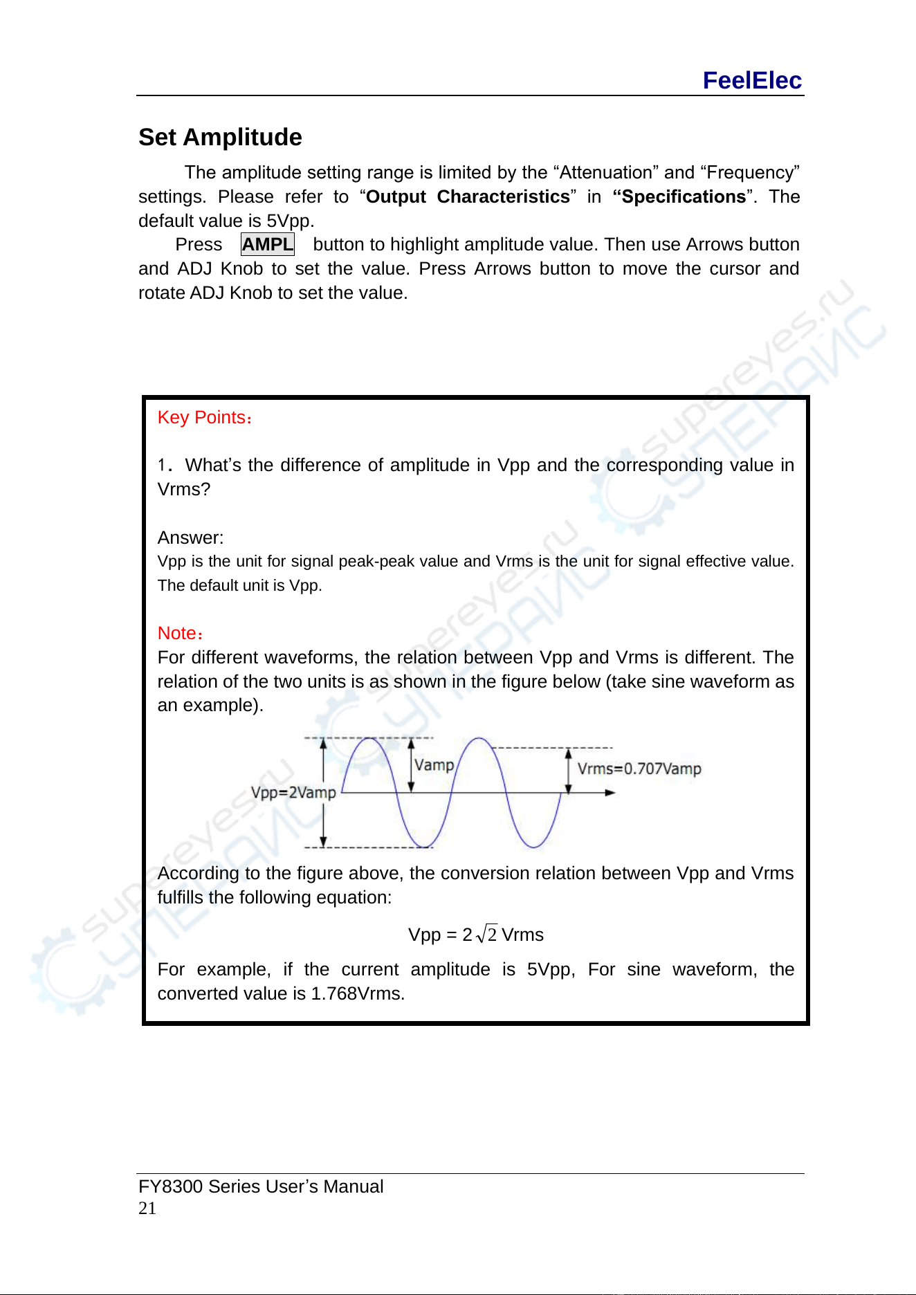
Key Points:
1.What’s the difference of amplitude in Vpp and the corresponding value in
Vrms?
Answer:
Vpp is the unit for signal peak-peak value and Vrms is the unit for signal effective value.
The default unit is Vpp.
Note:
For different waveforms, the relation between Vpp and Vrms is different. The
relation of the two units is as shown in the figure below (take sine waveform as
an example).
According to the figure above, the conversion relation between Vpp and Vrms
fulfills the following equation:
Vpp = 2
2
Vrms
For example, if the current amplitude is 5Vpp, For sine waveform, the
converted value is 1.768Vrms.
FeelElec
22 FY8300S Series User’s Manual
Set Offset
Press OFFS button to highlight offset value. Then use Arrows button and
ADJ Knob to set the value. Press Arrows button to move the cursor and rotate
ADJ Knob to set the value.
The offset accuracy is 1mV. i.e. 0.001V.
When frequency output is lower than 20MHz, the offset can be adjusted
during -12V~+12V.
When frequency output is higher than 20MHz, the offset can be adjusted
during -2.5V~+2.5V.
FeelElec
FY8300 Series User’s Manual
23
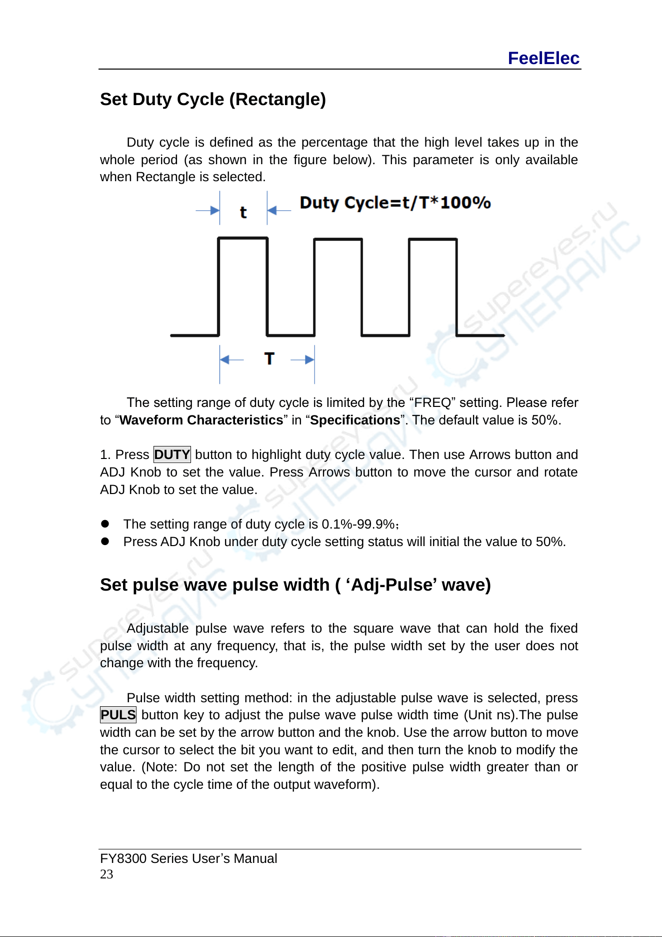
Set Duty Cycle (Rectangle)
Duty cycle is defined as the percentage that the high level takes up in the
whole period (as shown in the figure below). This parameter is only available
when Rectangle is selected.
The setting range of duty cycle is limited by the “FREQ” setting. Please refer
to “Waveform Characteristics” in “Specifications”. The default value is 50%.
1. Press DUTY button to highlight duty cycle value. Then use Arrows button and
ADJ Knob to set the value. Press Arrows button to move the cursor and rotate
ADJ Knob to set the value.
⚫ The setting range of duty cycle is 0.1%-99.9%;
⚫ Press ADJ Knob under duty cycle setting status will initial the value to 50%.
Set pulse wave pulse width ( ‘Adj-Pulse’ wave)
Adjustable pulse wave refers to the square wave that can hold the fixed
pulse width at any frequency, that is, the pulse width set by the user does not
change with the frequency.
Pulse width setting method: in the adjustable pulse wave is selected, press
PULS button key to adjust the pulse wave pulse width time (Unit ns).The pulse
width can be set by the arrow button and the knob. Use the arrow button to move
the cursor to select the bit you want to edit, and then turn the knob to modify the
value. (Note: Do not set the length of the positive pulse width greater than or
equal to the cycle time of the output waveform).
FeelElec
24 FY8300S Series User’s Manual
Set Phase
The setting range of phase is from 0° to 359.9°. The phase resolution is 0.1°.
The default phase value is 0°
The start phase displayed on the screen is the default value or the phase
previously set.
Then press PHAS button to highlight phase value. Then use Arrows button
and ADJ Knob to set the value. Press Arrows button to move the cursor and
rotate ADJ Knob to set the value.
FeelElec
FY8300 Series User’s Manual
25
Enable Output
After configuring the parameters of the waveform selected, waveform output
could be enabled.
At start-up output of CH1,CH2and CH3 are both turned on as default. At this time
indicator lights of three channels illuminate.
The default status can be modified. Press【SYS】button and then press【MORE】
button to set the output status of three channels.
For CH1 there are two status:
1) Generator is in parameter setting status and current channel selected is
CH1, then press CH1 to switch between output ON/OFF.
2) Generator is in other working status or current channel selected is not
CH1, then press CH1 to make CH1 as channel selected and press CH1
again to switch between output ON/OFF.
For CH2 there are two status:
1) Generator is in parameter setting status and current channel selected is
CH2, then press CH2 to switch between output ON/OFF.
2) Generator is in other working status or current channel selected is not
CH2, then press CH2 to make CH2 as channel selected and press CH2
again to switch between output ON/OFF.
For CH3 there are two status:
1) Generator is in parameter setting status and current channel selected is
CH3, then press CH3 to switch between output ON/OFF.
2) Generator is in other working status or current channel selected is not
CH3, then press CH3 to make CH3 as channel selected and press CH3
again to switch between output ON/OFF.
FeelElec
26 FY8300S Series User’s Manual
Example:Output Sine Waveform
This section mainly introduces how to output a sine waveform (Frequency:
20kHz, Amplitude:2.5Vpp, DC Offset: 1.6VDC, Start Phase: 90.9°) from the [CH1]
channel.
1. Select output channel
Press CH1 to select CH1. Now all characters and border of the channel is
displayed in yellow.
2. Select the Sine
Press WAVE button to select Sine. Then the diagram of Sine displays on the
screen.
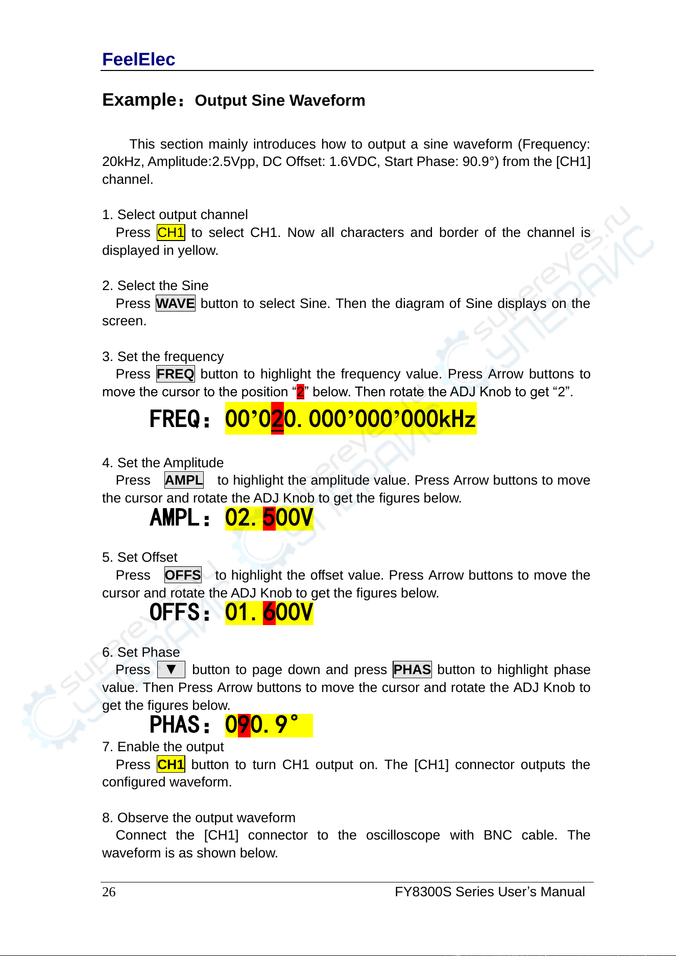
3. Set the frequency
Press FREQ button to highlight the frequency value. Press Arrow buttons to
move the cursor to the position “2” below. Then rotate the ADJ Knob to get “2”.
FREQ:00’020.000’000’000kHz
4. Set the Amplitude
Press AMPL to highlight the amplitude value. Press Arrow buttons to move
the cursor and rotate the ADJ Knob to get the figures below.
AMPL:02.500V
5. Set Offset
Press OFFS to highlight the offset value. Press Arrow buttons to move the
cursor and rotate the ADJ Knob to get the figures below.
OFFS:01.600V
6. Set Phase
Press ▼ button to page down and press PHAS button to highlight phase
value. Then Press Arrow buttons to move the cursor and rotate the ADJ Knob to
get the figures below.
PHAS:090.9°
7. Enable the output
Press CH1 button to turn CH1 output on. The [CH1] connector outputs the
configured waveform.
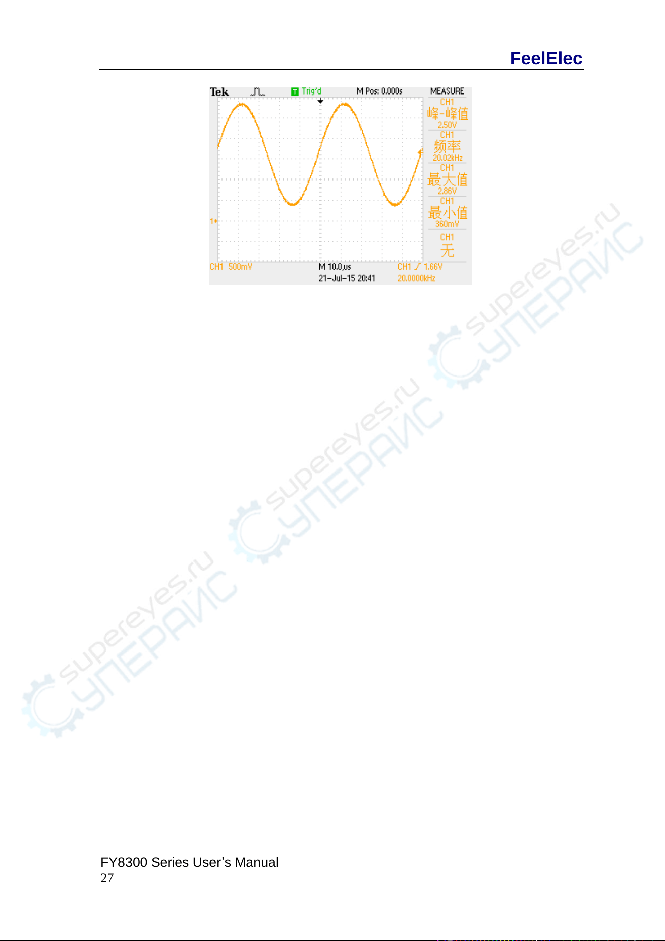
8. Observe the output waveform
Connect the [CH1] connector to the oscilloscope with BNC cable. The
waveform is as shown below.
FeelElec
FY8300 Series User’s Manual
27
FeelElec
28 FY8300S Series User’s Manual
Burst
FY8300S can output waveform with specified number of cycles (called Burst)
from the CH1 channel. FY8300S supports control of burst output by CH2(internal),
manual or external trigger source; The signal generator can generate burst using
Sine wave, Square wave, Ramp wave, Pulse, Noise wave or arbitrary waveform
(except DC).
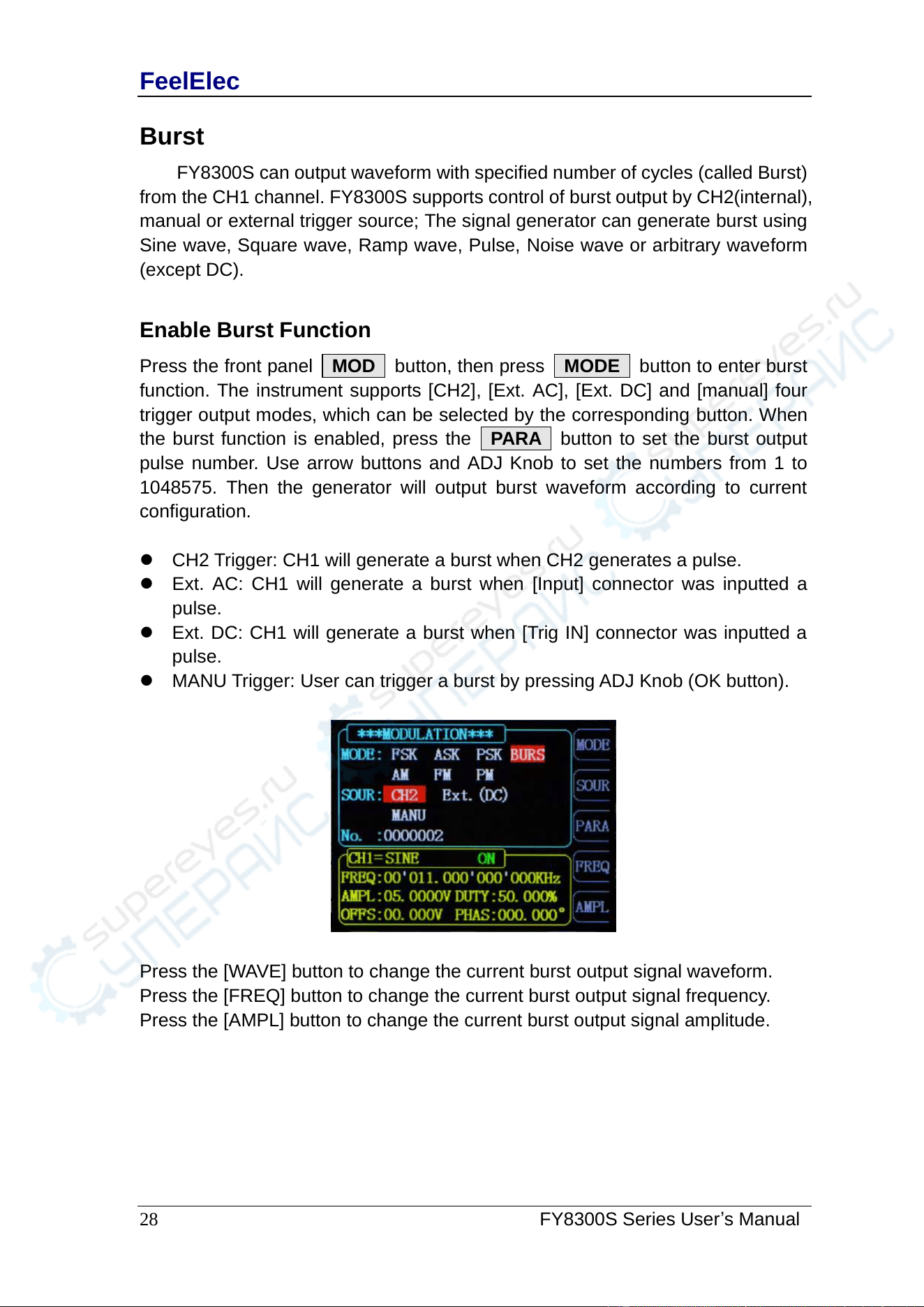
Enable Burst Function
Press the front panel MOD button, then press MODE button to enter burst
function. The instrument supports [CH2], [Ext. AC], [Ext. DC] and [manual] four
trigger output modes, which can be selected by the corresponding button. When
the burst function is enabled, press the PARA button to set the burst output
pulse number. Use arrow buttons and ADJ Knob to set the numbers from 1 to
1048575. Then the generator will output burst waveform according to current
configuration.
⚫ CH2 Trigger: CH1 will generate a burst when CH2 generates a pulse.
⚫ Ext. AC: CH1 will generate a burst when [Input] connector was inputted a
pulse.
⚫ Ext. DC: CH1 will generate a burst when [Trig IN] connector was inputted a
pulse.
⚫ MANU Trigger: User can trigger a burst by pressing ADJ Knob (OK button).
Press the [WAVE] button to change the current burst output signal waveform.
Press the [FREQ] button to change the current burst output signal frequency.
Press the [AMPL] button to change the current burst output signal amplitude.
FeelElec
FY8300 Series User’s Manual
29
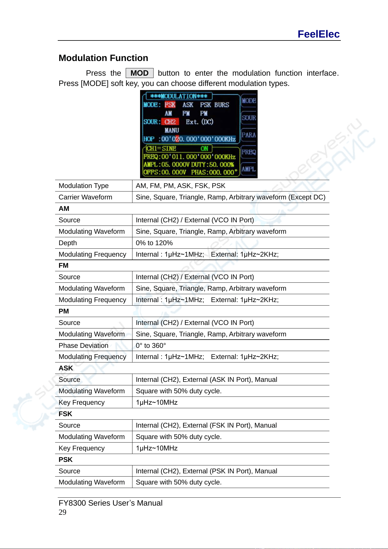
Modulation Function
Press the MOD button to enter the modulation function interface.
Press [MODE] soft key, you can choose different modulation types.
Modulation Type
AM, FM, PM, ASK, FSK, PSK
Carrier Waveform
Sine, Square, Triangle, Ramp, Arbitrary waveform (Except DC)
AM
Source
Internal (CH2) / External (VCO IN Port)
Modulating Waveform
Sine, Square, T r iangle, Ramp, Arbitrary waveform
Depth
0% to 120%
Modulating Frequency
Internal : 1μHz~1MHz; External: 1μHz~2KHz;
FM
Source
Internal (CH2) / External (VCO IN Port)
Modulating Waveform
Sine, Square, Triangle, Ramp, Arbitrary waveform
Modulating Frequency
Internal : 1μHz~1MHz; External: 1μHz~2KHz;
PM
Source
Internal (CH2) / External (VCO IN Port)
Modulating Waveform
Sine, Square, Triangle, Ramp, Arbitrary waveform
Phase Deviation
0° to 360°
Modulating Frequency
Internal : 1μHz~1MHz; External: 1μHz~2KHz;
ASK
Source
Internal (CH2), External (ASK IN Port), Manual
Modulating Waveform
Square with 50% duty cycle.
Key Frequency
1μHz~10MHz
FSK
Source
Internal (CH2), External (FSK IN Port), Manual
Modulating Waveform
Square with 50% duty cycle.
Key Frequency
1μHz~10MHz
PSK
Source
Internal (CH2), External (PSK IN Port), Manual
Modulating Waveform
Square with 50% duty cycle.
FeelElec
30 FY8300S Series User’s Manual
Key Frequency
1μHz~10MHz
FeelElec
FY8300 Series User’s Manual
31
Frequency Meter/Counter
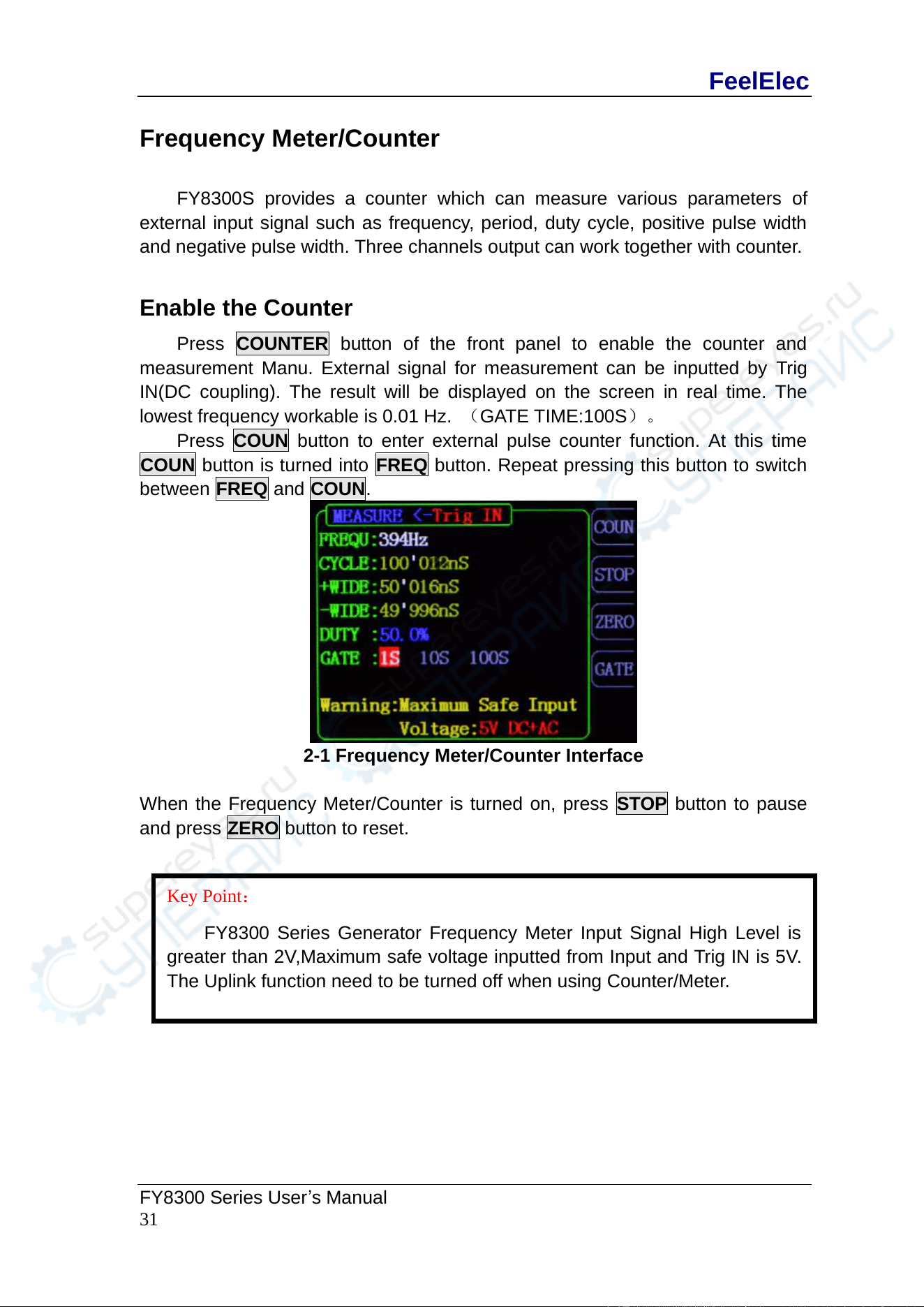
FY8300S provides a counter which can measure various parameters of
external input signal such as frequency, period, duty cycle, positive pulse width
and negative pulse width. Three channels output can work together with counter.
Enable the Counter
Press COUNTER button of the front panel to enable the counter and
measurement Manu. External signal for measurement can be inputted by Trig
IN(DC coupling). The result will be displayed on the screen in real time. The
lowest frequency workable is 0.01 Hz. (GATE TIME:100S)。
Press COUN button to enter external pulse counter function. At this time
COUN button is turned into FREQ button. Repeat pressing this button to switch
between FREQ and COUN.
2-1 Frequency Meter/Counter Interface
When the Frequency Meter/Counter is turned on, press STOP button to pause
and press ZERO button to reset.
Key Point:
FY8300 Series Generator Frequency Meter Input Signal High Level is
greater than 2V,Maximum safe voltage inputted from Input and Trig IN is 5V .
The Uplink function need to be turned off when using Counter/Meter.
FeelElec
32 FY8300S Series User’s Manual
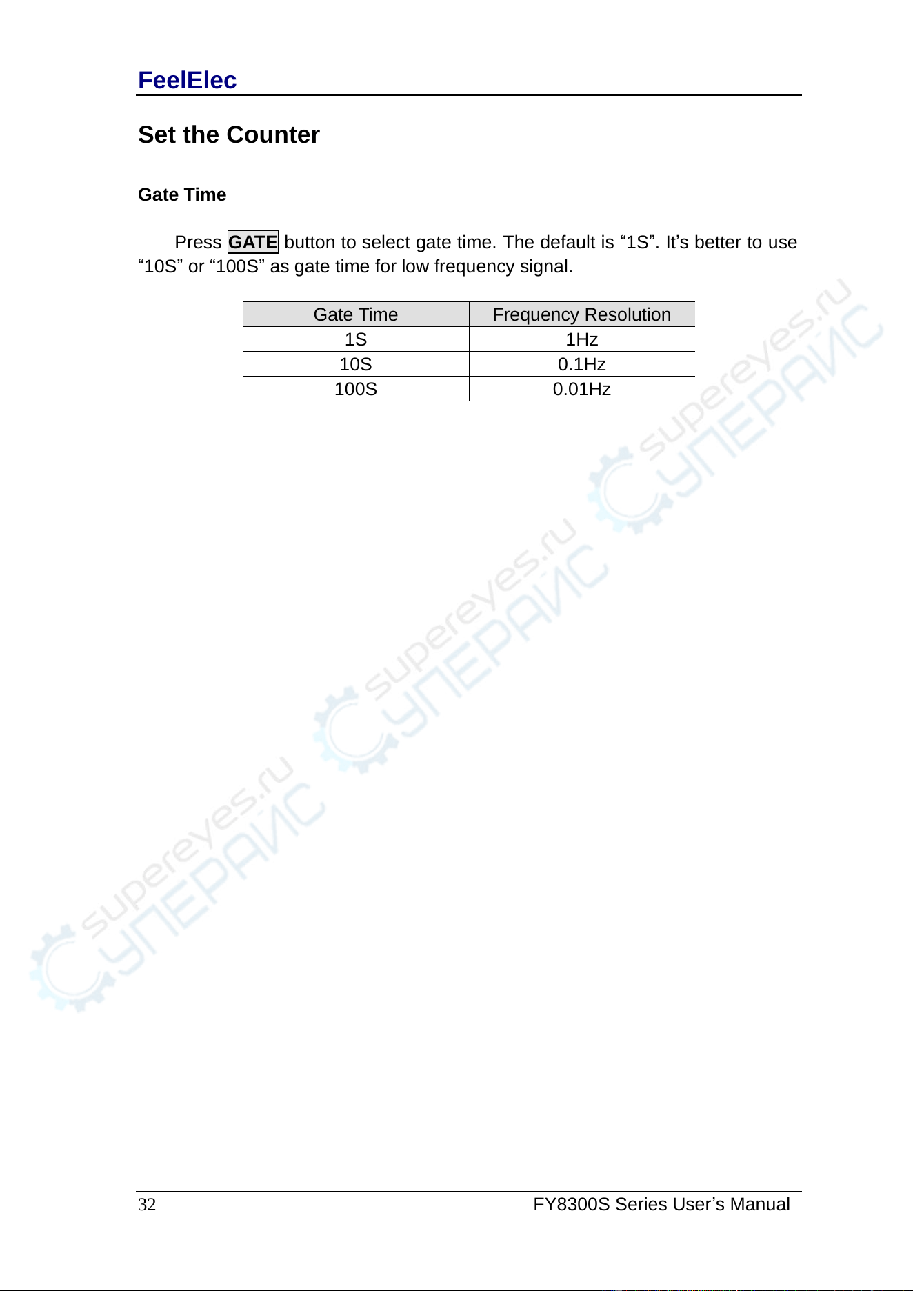
Set the Counter
Gate Time
Press GATE button to select gate time. The default is “1S”. It’s better to use
“10S” or “100S” as gate time for low frequency signal.
Gate Time
Frequency Resolution
1S
1Hz
10S
0.1Hz
100S
0.01Hz
FeelElec
FY8300 Series User’s Manual
33
Sweep
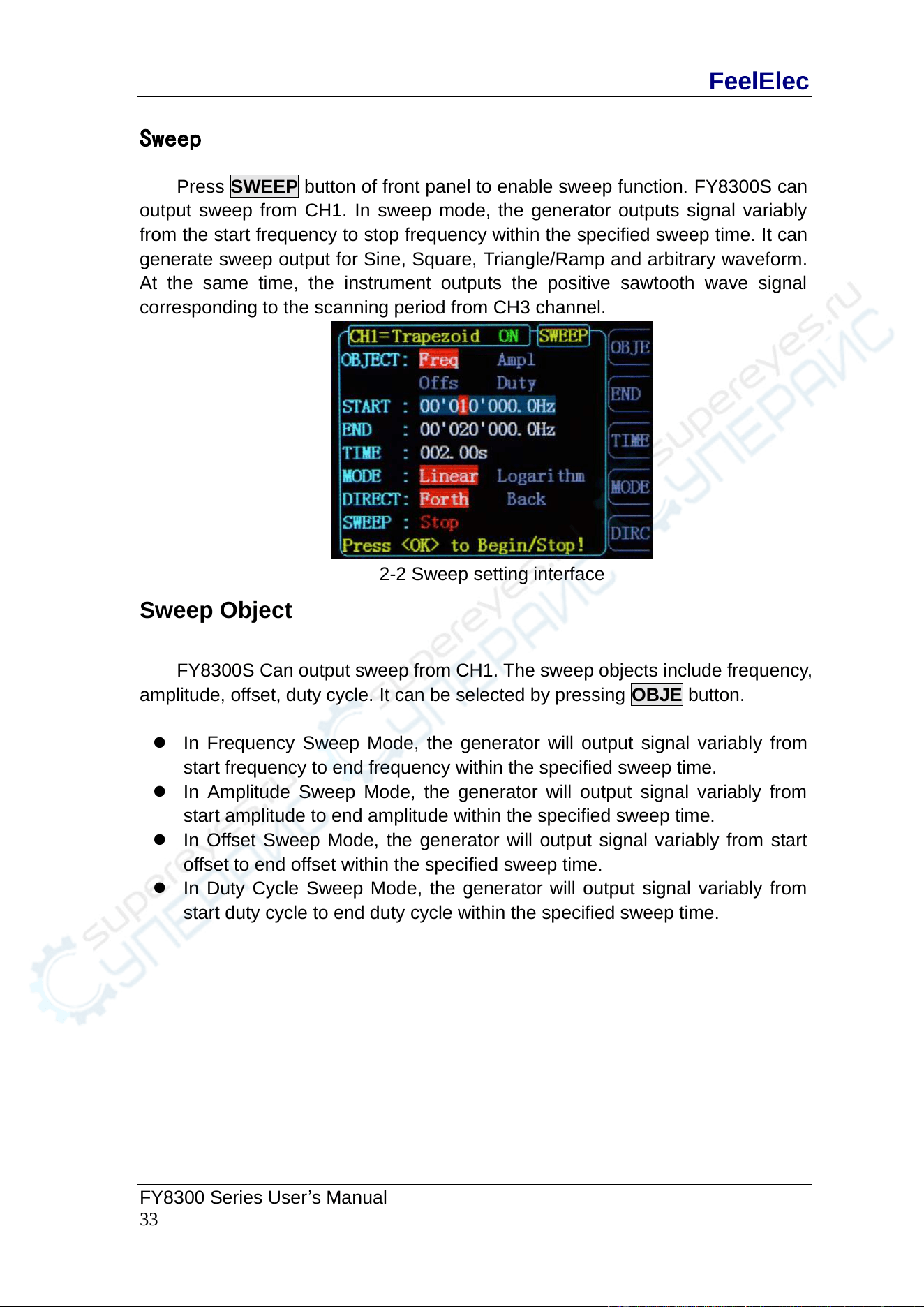
Press SWEEP button of front panel to enable sweep function. FY8300S can
output sweep from CH1. In sweep mode, the generator outputs signal variably
from the start frequency to stop frequency within the specified sweep time. It can
generate sweep output for Sine, Square, Triangle/Ramp and arbitrary waveform.
At the same time, the instrument outputs the positive sawtooth wave signal
corresponding to the scanning period from CH3 channel.
2-2 Sweep setting interface
Sweep Object
FY8300S Can output sweep from CH1. The sweep objects include frequency,
amplitude, offset, duty cycle. It can be selected by pressing OBJE button.
⚫ In Frequency Sweep Mode, the generator will output signal variably from
start frequency to end frequency within the specified sweep time.
⚫ In Amplitude Sweep Mode, the generator will output signal variably from
start amplitude to end amplitude within the specified sweep time.
⚫ In Offset Sweep Mode, the generator will output signal variably from start
offset to end offset within the specified sweep time.
⚫ In Duty Cycle Sweep Mode, the generator will output signal variably from
start duty cycle to end duty cycle within the specified sweep time.
FeelElec
34 FY8300S Series User’s Manual
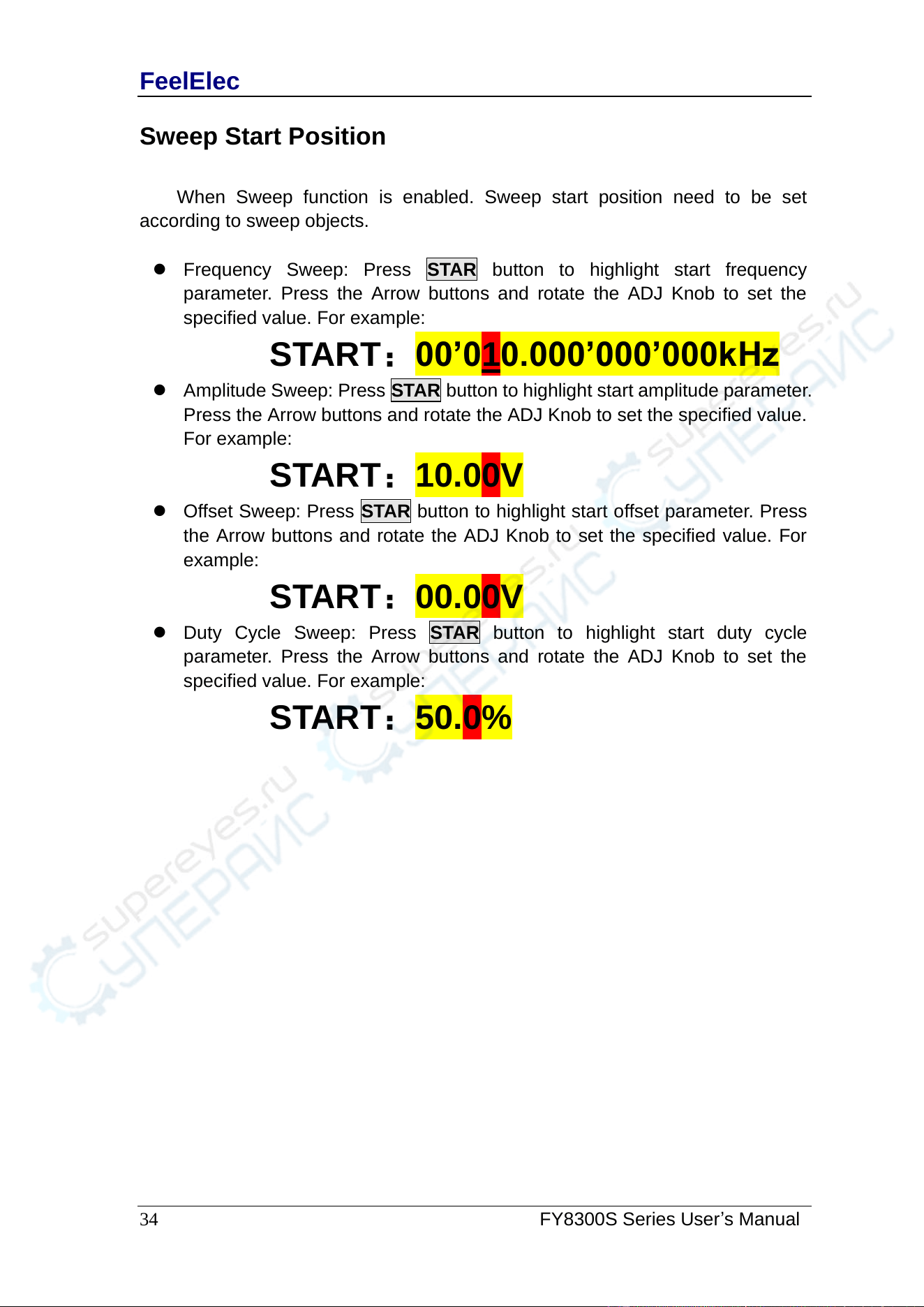
Sweep Start Position
When Sweep function is enabled. Sweep start position need to be set
according to sweep objects.
⚫ Frequency Sweep: Press STAR button to highlight start frequency
parameter. Press the Arrow buttons and rotate the ADJ Knob to set the
specified value. For example:
START:00’010.000’000’000kHz
⚫ Amplitude Sweep: Press STAR button to highlight start amplitude parameter.
Press the Arrow buttons and rotate the ADJ Knob to set the specified value.
For example:
START:10.00V
⚫ Offset Sweep: Press STAR button to highlight start offset parameter. Press
the Arrow buttons and rotate the ADJ Knob to set the specified value. For
example:
START:00.00V
⚫ Duty Cycle Sweep: Press STAR button to highlight start duty cycle
parameter. Press the Arrow buttons and rotate the ADJ Knob to set the
specified value. For example:
START:50.0%
FeelElec
FY8300 Series User’s Manual
35
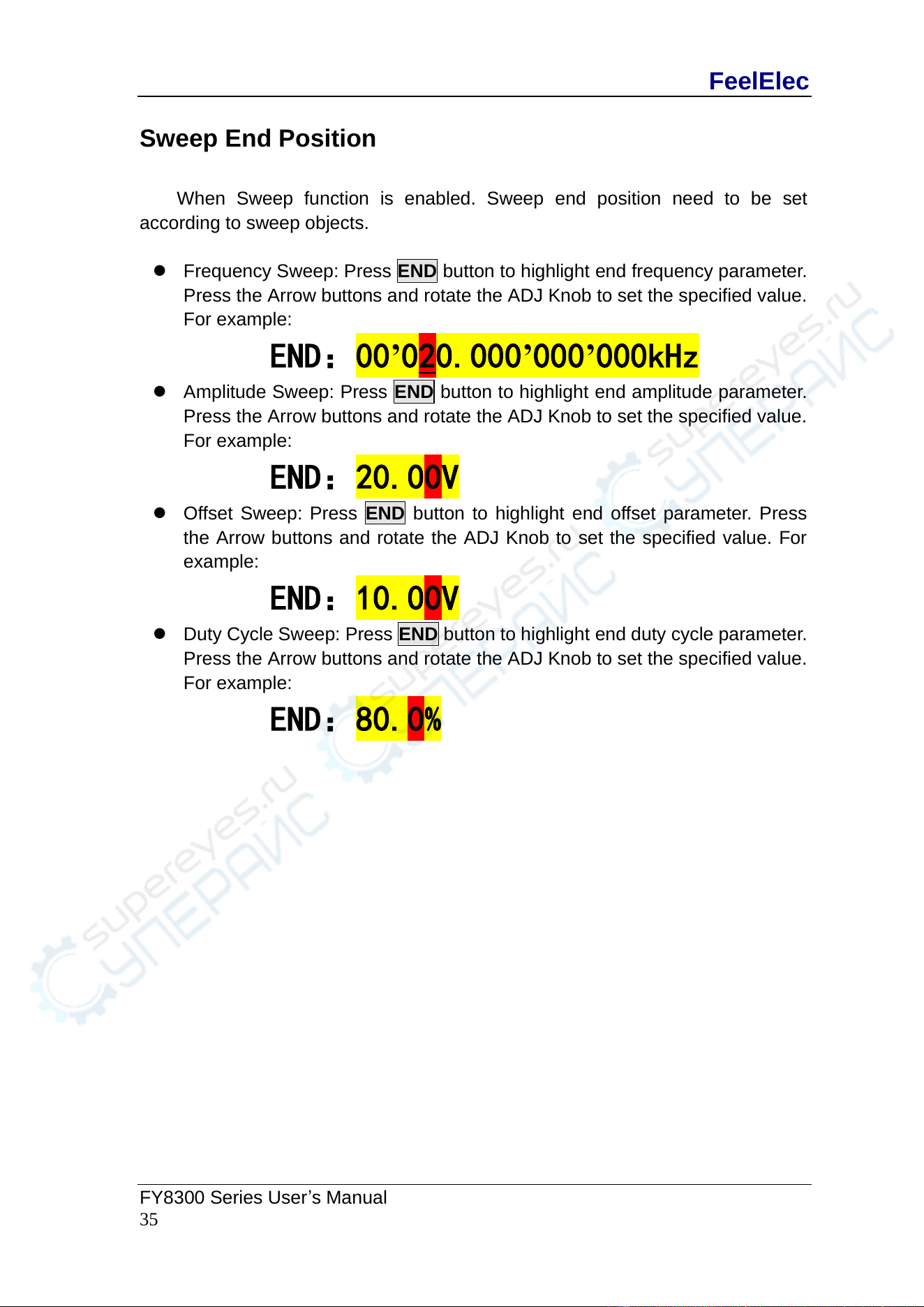
Sweep End Position
When Sweep function is enabled. Sweep end position need to be set
according to sweep objects.
⚫ Frequency Sweep: Press END button to highlight end frequency parameter.
Press the Arrow buttons and rotate the ADJ Knob to set the specified value.
For example:
END:00’020.000’000’000kHz
⚫ Amplitude Sweep: Press END button to highlight end amplitude parameter.
Press the Arrow buttons and rotate the ADJ Knob to set the specified value.
For example:
END:20.00V
⚫ Offset Sweep: Press END button to highlight end offset parameter. Press
the Arrow buttons and rotate the ADJ Knob to set the specified value. For
example:
END:10.00V
⚫ Duty Cycle Sweep: Press END button to highlight end duty cycle parameter.
Press the Arrow buttons and rotate the ADJ Knob to set the specified value.
For example:
END:80.0%
FeelElec
36 FY8300S Series User’s Manual
Sweep Time
When Sweep function is enabled, press SOUR button to select it and press it
again to change between TIME and external sweep (VCO Sweep). Press the
Arrow buttons and rotate the ADJ Knob to set the specified value of weep time.
The default is “10S”. The work range is 10mS~999.99S. For Example:
SOUR: TIME 999.99S
FeelElec
FY8300 Series User’s Manual
37
VCO (Voltage Control Output) Sweep
Function instruction: External voltage can control signal output by External
Sweep (VCO) function. It can realize voltage controlling frequency (VCF), voltage
controlling amplitude (VCA), voltage controlling offset, voltage controlling duty
cycle and so on.
Operation method: Press [SWEEP] button to enter sweep function interface.
Then press[F4 SOUR] button to switch the source to VCO IN. After Sweep Object,
Start, End and Sweep Mode being set, connect the external signal from VCO IN
terminal on the back panel. Then press the ADJ knob (OK button) to enable VCO
sweep function. Press ADJ knob (OK button) again to disable it.
Note: Signal input for External Sweep (VCO) need to be input from VCO IN port of
back panel. Its frequency need to be less than 500 Hz and its voltage amplitude
need to be among 0~5V.
FeelElec
38 FY8300S Series User’s Manual
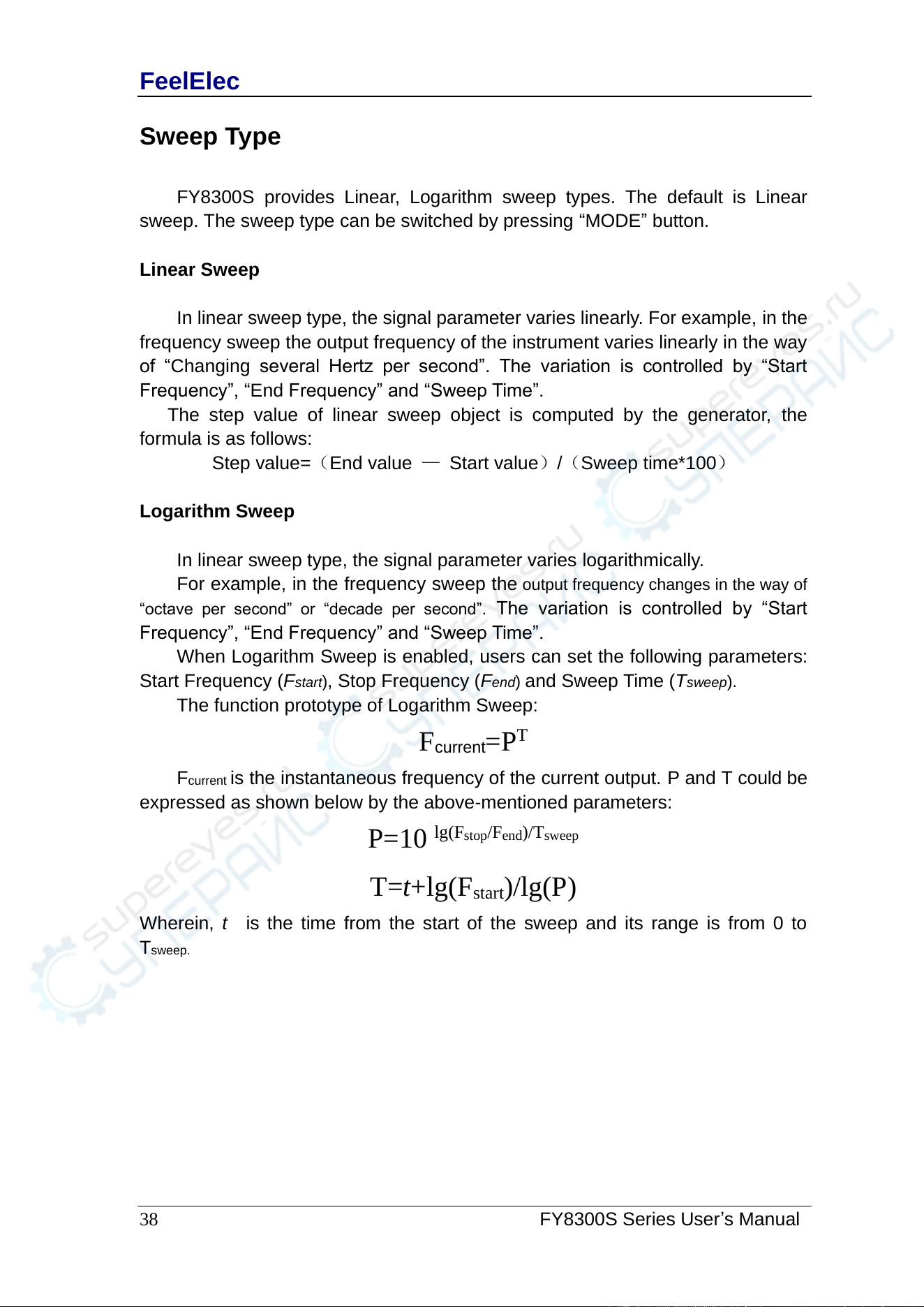
Sweep Type
FY8300S provides Linear, Logarithm sweep types. The default is Linear
sweep. The sweep type can be switched by pressing “MODE” button.
Linear Sweep
In linear sweep type, the signal parameter varies linearly. For example, in the
frequency sweep the output frequency of the instrument varies linearly in the way
of “Changing several Hertz per second”. The variation is controlled by “Start
Frequency”, “End Frequency” and “Sweep Time”.
The step value of linear sweep object is computed by the generator, the
formula is as follows:
Step value=(End value — Start value)/(Sweep time*100)
Logarithm Sweep
In linear sweep type, the signal parameter varies logarithmically.
For example, in the frequency sweep the output frequency changes in the way of
“octave per second” or “decade per second”. The variation is controlled by “Start
Frequency”, “End Frequency” and “Sweep Time”.
When Logarithm Sweep is enabled, users can set the following parameters:
Start Frequency (Fstart), Stop Frequency (Fend) and Sweep Time (Tsweep).
The function prototype of Logarithm Sweep:
F
current
=P
T
F
current
is the instantaneous frequency of the current output. P and T could be
expressed as shown below by the above-mentioned parameters:
P=10
lg(F
stop
/F
end
)/T
sweep
T=t+lg(F
start
)/lg(P)
Wherein, t is the time from the start of the sweep and its range is from 0 to
T
sweep.
FeelElec
FY8300 Series User’s Manual
39
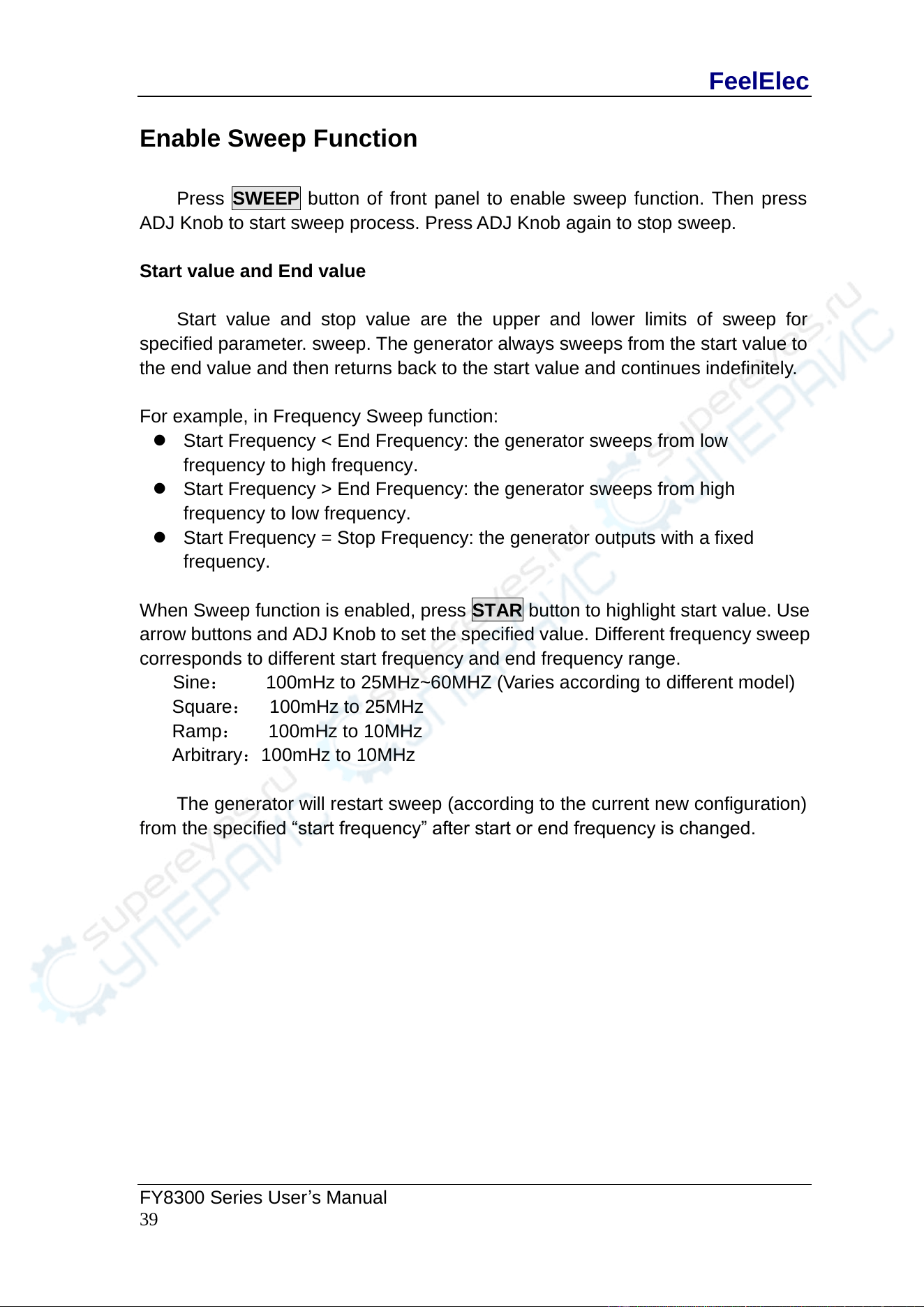
Enable Sweep Function
Press SWEEP button of front panel to enable sweep function. Then press
ADJ Knob to start sweep process. Press ADJ Knob again to stop sweep.
Start value and End value
Start value and stop value are the upper and lower limits of sweep for
specified parameter. sweep. The generator always sweeps from the start value to
the end value and then returns back to the start value and continues indefinitely.
For example, in Frequency Sweep function:
⚫ Start Frequency < End Frequency: the generator sweeps from low
frequency to high frequency.
⚫ Start Frequency > End Frequency: the generator sweeps from high
frequency to low frequency.
⚫ Start Frequency = Stop Frequency: the generator outputs with a fixed
frequency.
When Sweep function is enabled, press STAR button to highlight start value. Use
arrow buttons and ADJ Knob to set the specified value. Different frequency sweep
corresponds to different start frequency and end frequency range.
Sine: 100mHz to 25MHz~60MHZ (Varies according to different model)
Square: 100mHz to 25MHz
Ramp: 100mHz to 10MHz
Arbitrary:100mHz to 10MHz
The generator will restart sweep (according to the current new configuration)
from the specified “start frequency” after start or end frequency is changed.
FeelElec
40 FY8300S Series User’s Manual
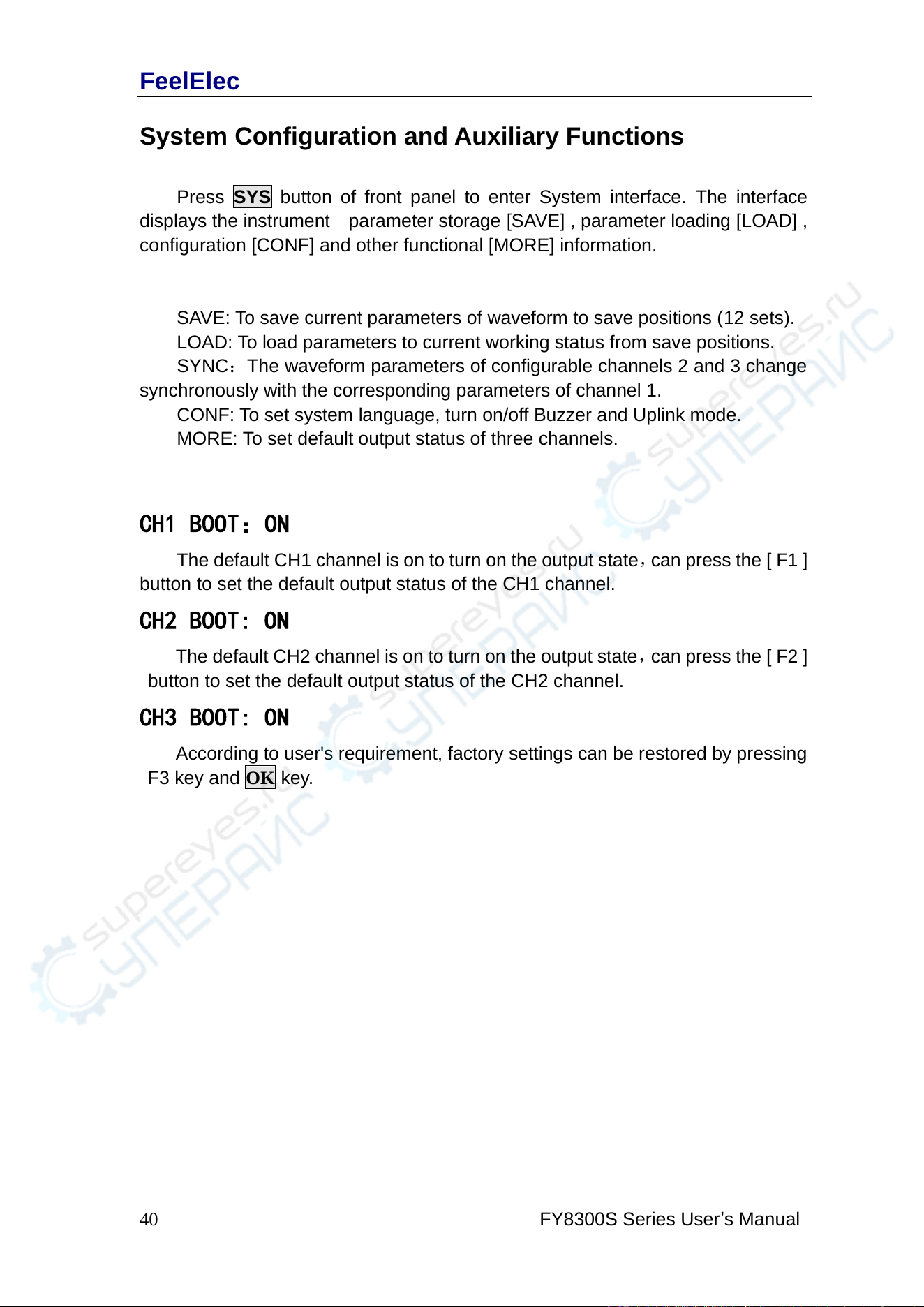
System Configuration and Auxiliary Functions
Press SYS button of front panel to enter System interface. The interface
displays the instrument parameter storage [SAVE] , parameter loading [LOAD] ,
configuration [CONF] and other functional [MORE] information.
SAVE: To save current parameters of waveform to save positions (12 sets).
LOAD: To load parameters to current working status from save positions.
SYNC:The waveform parameters of configurable channels 2 and 3 change
synchronously with the corresponding parameters of channel 1.
CONF: To set system language, turn on/off Buzzer and Uplink mode.
MORE: To set default output status of three channels.
CH1 BOOT:ON
The default CH1 channel is on to turn on the output state,can press the [ F1 ]
button to set the default output status of the CH1 channel.
CH2 BOOT: ON
The default CH2 channel is on to turn on the output state,can press the [ F2 ]
button to set the default output status of the CH2 channel.
CH3 BOOT: ON
According to user's requirement, factory settings can be restored by pressing
F3 key and OK key.
FeelElec
FY8300 Series User’s Manual
41
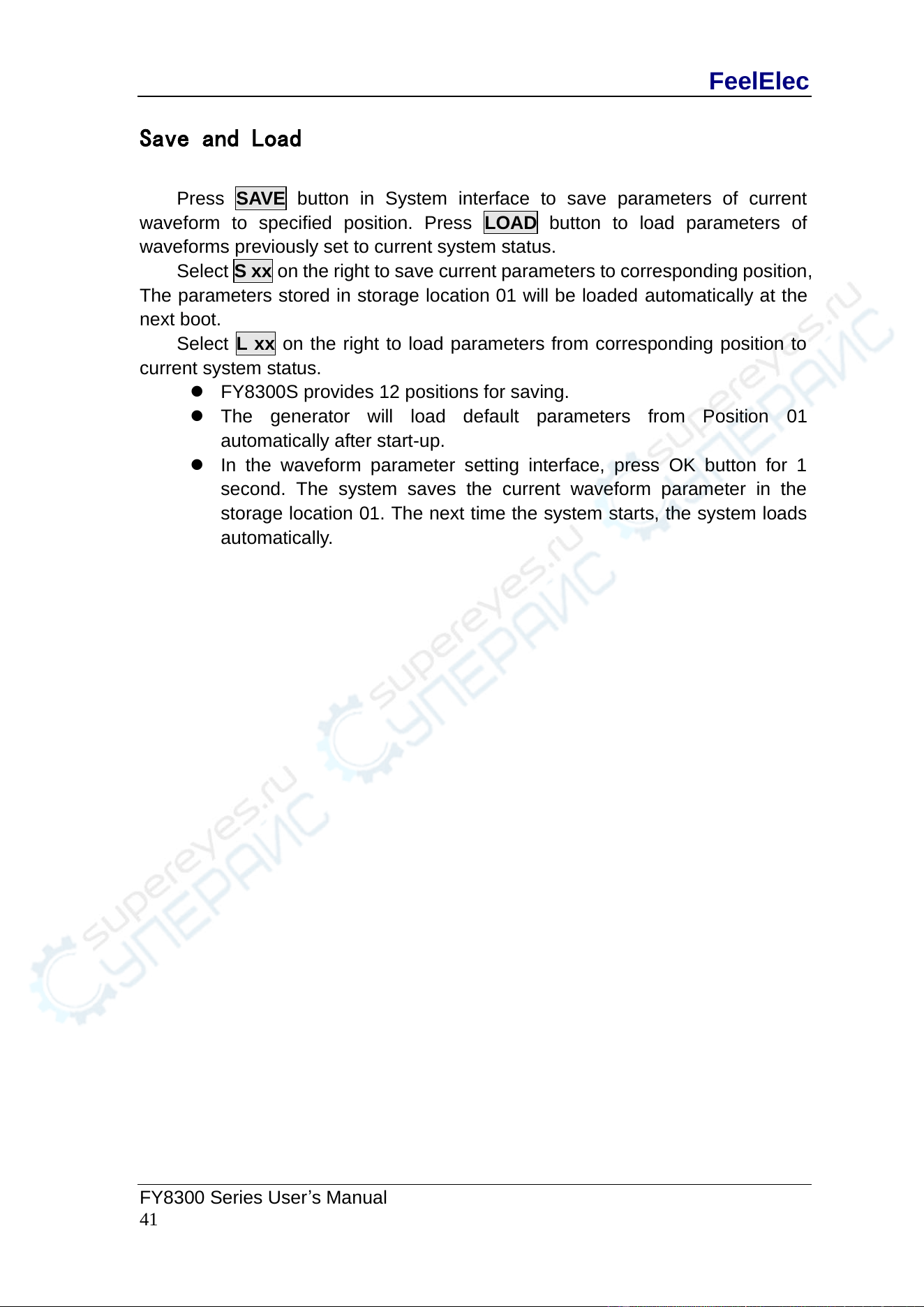
Save and Load
Press SAVE button in System interface to save parameters of current
waveform to specified position. Press LOAD button to load parameters of
waveforms previously set to current system status.
Select S xx on the right to save current parameters to corresponding position,
The parameters stored in storage location 01 will be loaded automatically at the
next boot.
Select L xx on the right to load parameters from corresponding position to
current system status.
⚫ FY8300S provides 12 positions for saving.
⚫ The generator will load default parameters from Position 01
automatically after start-up.
⚫ In the waveform parameter setting interface, press OK button for 1
second. The system saves the current waveform parameter in the
storage location 01. The next time the system starts, the system loads
automatically.
FeelElec
42 FY8300S Series User’s Manual
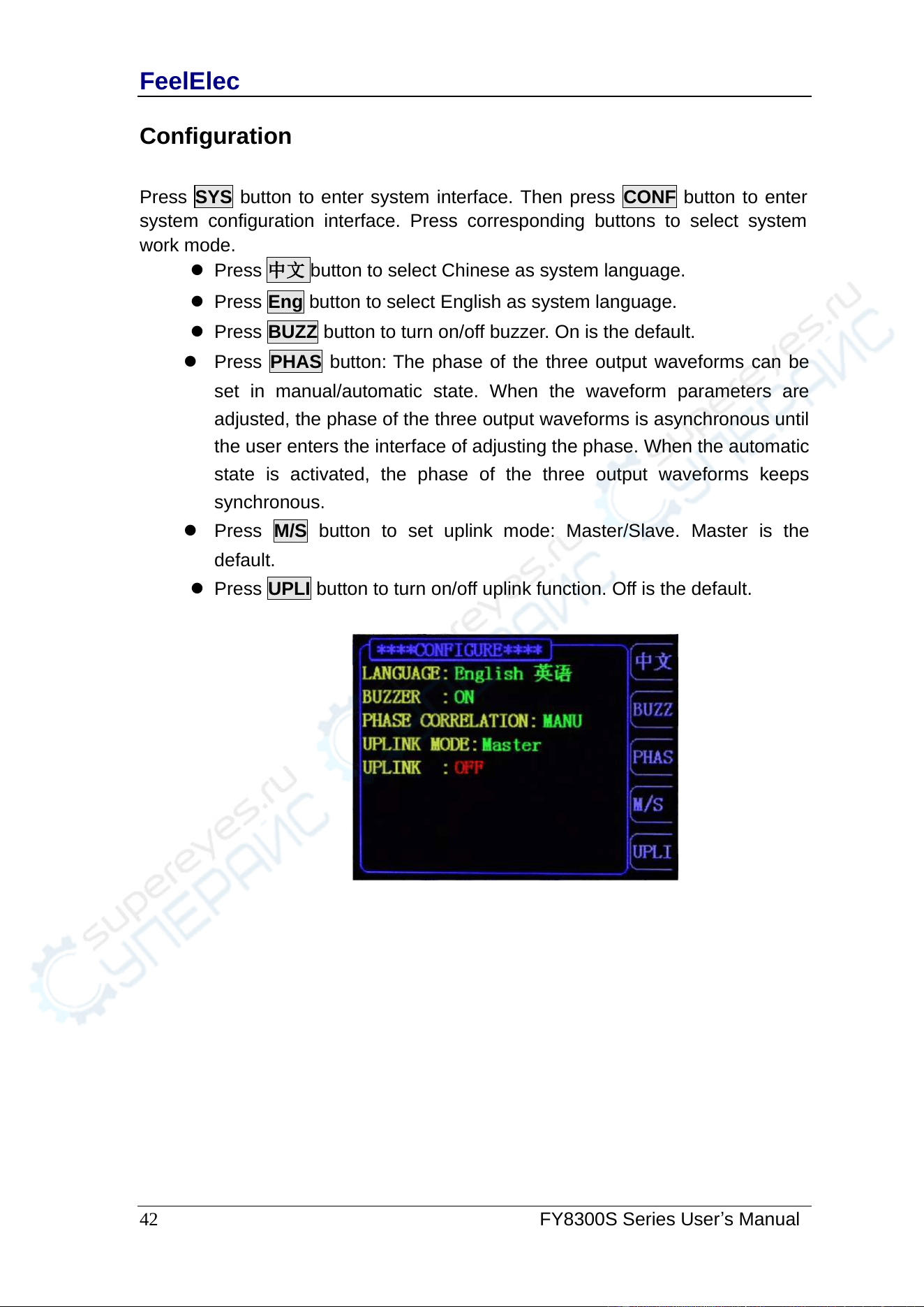
Configuration
Press SYS button to enter system interface. Then press CONF button to enter
system configuration interface. Press corresponding buttons to select system
work mode.
⚫ Press 中文 button to select Chinese as system language.
⚫ Press Eng button to select English as system language.
⚫ Press BUZZ button to turn on/off buzzer. On is the default.
⚫ Press PHAS button: The phase of the three output waveforms can be
set in manual/automatic state. When the waveform parameters are
adjusted, the phase of the three output waveforms is asynchronous until
the user enters the interface of adjusting the phase. When the automatic
state is activated, the phase of the three output waveforms keeps
synchronous.
⚫ Press M/S button to set uplink mode: Master/Slave. Master is the
default.
⚫ Press UPLI button to turn on/off uplink function. Off is the default.
FeelElec
FY8300 Series User’s Manual
43
Uplink
FY8300S supports multi-machine uplink, which can provide users more
channels for output. In uplink network, only one master machine can exist. Others
must be set as slave machine. The setting method is as follows:
⚫ Select on FY8300S as master machine. Press SYS -> CONF ->M/S, to set
the UPLINK MODE to be “Master”. Press UPLI, to set the UPLINK to be
“ON”.
⚫ Set all other machines to be slave machines. Press SYS -> CONF ->M/S, to
set the UPLINK MODE to be “Slave”. Press UPLI, to set the UPLINK to be
“ON”. Repeat this step to set all slave machines.
⚫ Connect all FY8300S in parallel by SYNC connecter.
⚫ The uplink machines cannot exceed 8 because the driving ability.
When the setting above has been finished, all machines in network will work
synchronously according to the start phase of master machine. When outputting
signal with same frequency, multi channels output can be executed with phase
adjustable.
FeelElec
44 FY8300S Series User’s Manual
Synchronization
Press the [SYNC] button to enter the synchronization function setting
interface. Press corresponding buttons on the right to highlight or cancel selecting
status.
When the synchronization of corresponding parameters are activated, the
corresponding parameters of CH2,CH3 will vary according to variation of CH1
automatically. The parameters workable for synchronization include waveform,
frequency, amplitude, offset, and duty cycle, which can be set separately.
When WAVE is highlighted, the waveform of CH2,CH3 will vary according to
variation of CH1.
When FREQ is highlighted, the frequency of CH2,CH3 will vary according to
variation of CH1.
When AMPL is highlighted, the amplitude of CH2,CH3 will vary according to
variation of CH1.
When OFFS is highlighted, the offset of CH2,CH3 will vary according to
variation of CH1.
When CH is highlighted, the output state of CH2,CH3 will vary according to
variation of CH1.
When DUTY is highlighted, the duty cycle of CH2,CH3 will vary according to
variation of CH1.
When RISE is highlighted, the Rising edge time of CH2,CH3 will vary
according to variation of CH1.
When FALL is highlighted, the Decline edge time of CH2,CH3 will vary
according to variation of CH1.
Key points:
The synchronization function of FY8300 series generators will be
automatically saved after each setup, and the system will still be valid after
restart. When the user can not correctly change the system parameters,
please confirm whether the step function has been opened.
FeelElec
FY8300 Series User’s Manual
45
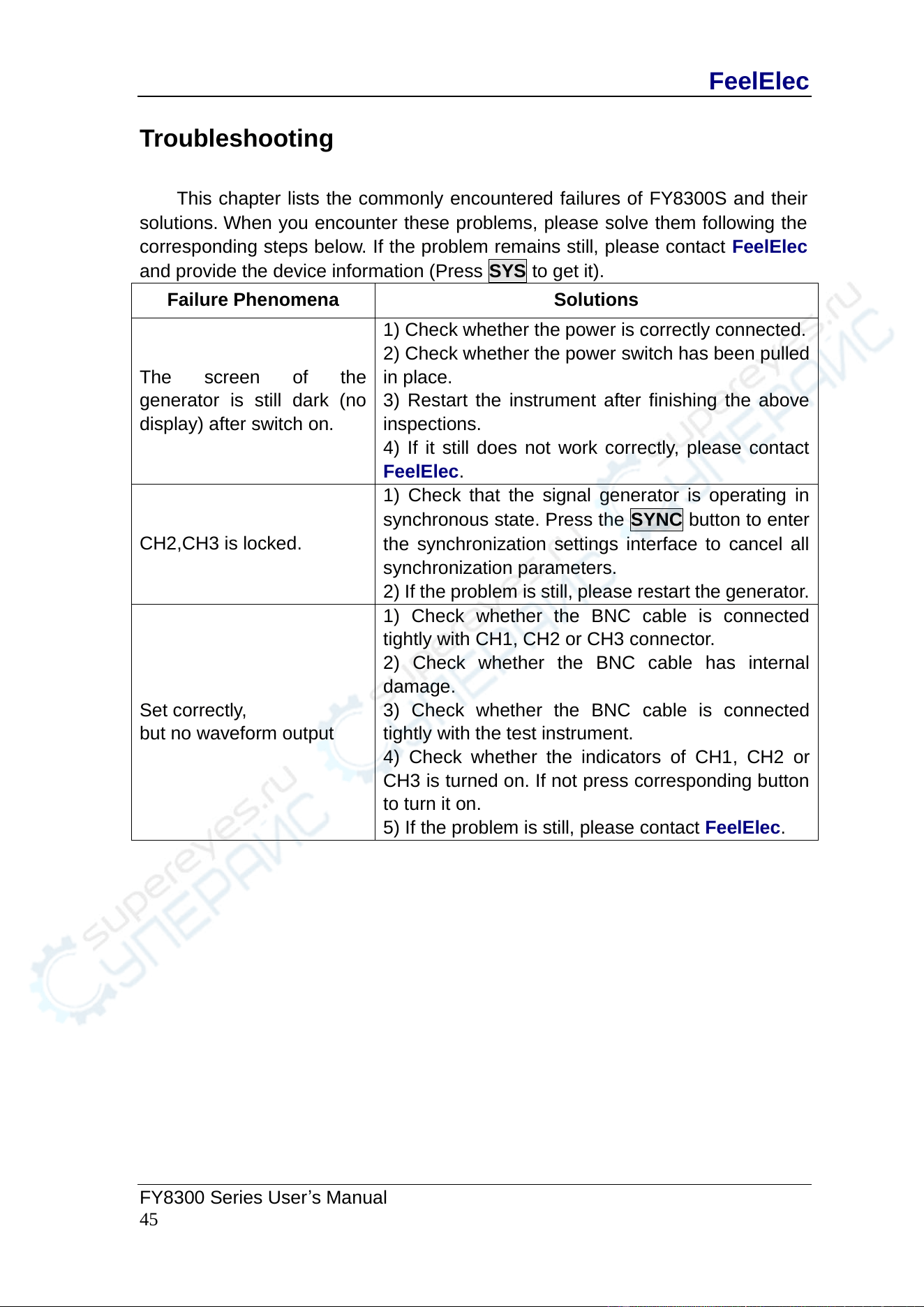
Troubleshooting
This chapter lists the commonly encountered failures of FY8300S and their
solutions. When you encounter these problems, please solve them following the
corresponding steps below. If the problem remains still, please contact FeelElec
and provide the device information (Press SYS to get it).
Failure Phenomena
Solutions
The screen of the
generator is still dark (no
display) after switch on.
1) Check whether the power is correctly connected.
2) Check whether the power switch has been pulled
in place.
3) Restart the instrument after finishing the above
inspections.
4) If it still does not work correctly, please contact
FeelElec.
CH2,CH3 is locked.
1) Check that the signal generator is operating in
synchronous state. Press the SYNC button to enter
the synchronization settings interface to cancel all
synchronization parameters.
2) If the problem is still, please restart the generator.
Set correctly,
but no waveform output
1) Check whether the BNC cable is connected
tightly with CH1, CH2 or CH3 connector.
2) Check whether the BNC cable has internal
damage.
3) Check whether the BNC cable is connected
tightly with the test instrument.
4) Check whether the indicators of CH1, CH2 or
CH3 is turned on. If not press corresponding button
to turn it on.
5) If the problem is still, please contact FeelElec.
FeelElec
46 FY8300S Series User’s Manual
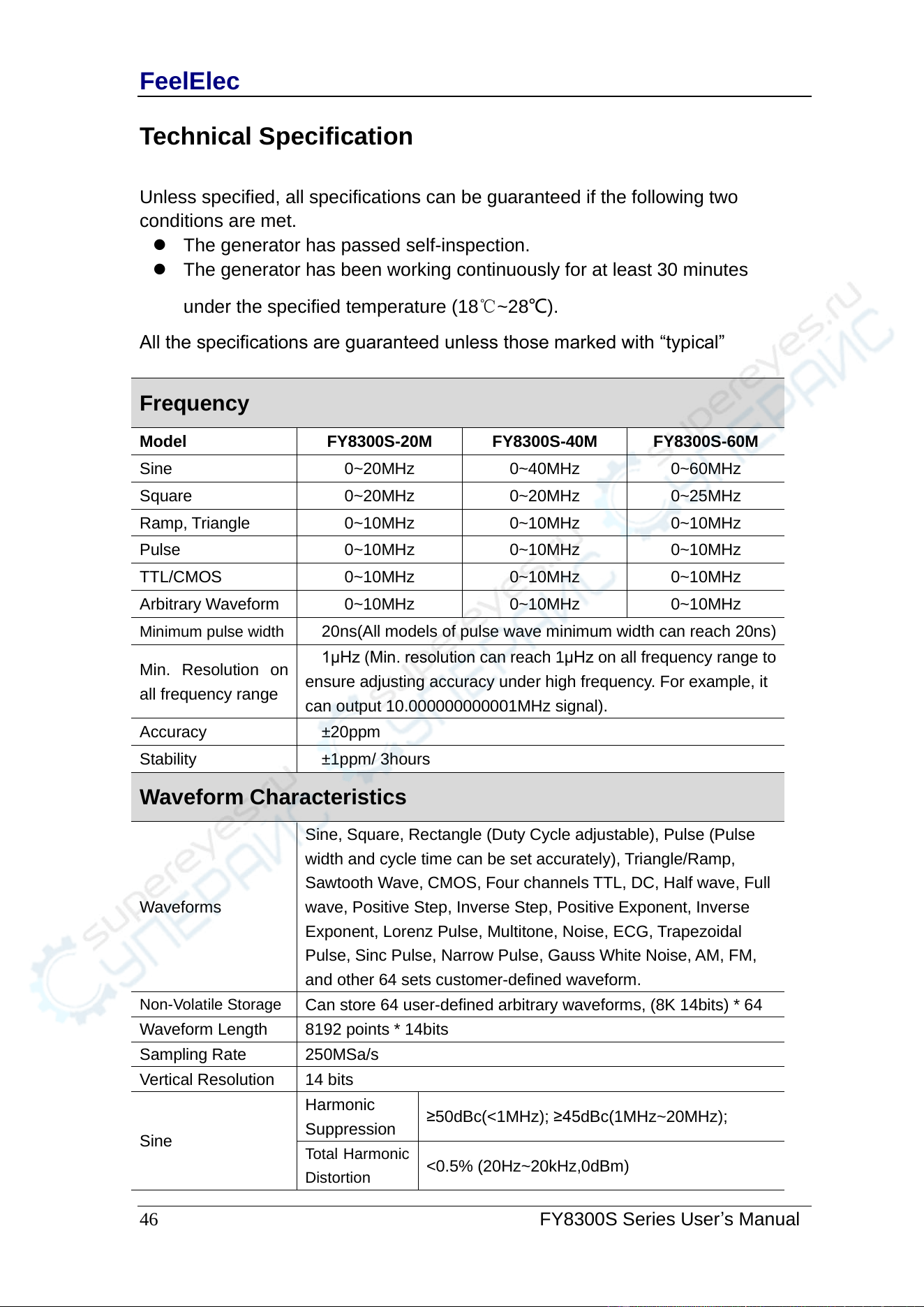
Technical Specification
Unless specified, all specifications can be guaranteed if the following two
conditions are met.
⚫ The generator has passed self-inspection.
⚫ The generator has been working continuously for at least 30 minutes
under the specified temperature (18℃~28℃).
All the specifications are guaranteed unless those marked with “typical”
Frequency
Model
FY8300S-20M
FY8300S-40M
FY8300S-60M
Sine
0~20MHz
0~40MHz
0~60MHz
Square
0~20MHz
0~20MHz
0~25MHz
Ramp, Triangle
0~10MHz
0~10MHz
0~10MHz
Pulse
0~10MHz
0~10MHz
0~10MHz
TTL/CMOS
0~10MHz
0~10MHz
0~10MHz
Arbitrary Waveform
0~10MHz
0~10MHz
0~10MHz
Minimum pulse width
20ns(All models of pulse wave minimum width can reach 20ns)
Min. Resolution on
all frequency range
1μHz (Min. resolution can reach 1μHz on all frequency range to
ensure adjusting accuracy under high frequency. For example, it
can output 10.000000000001MHz signal).
Accuracy
±20ppm
Stability
±1ppm/ 3hours
Waveform Characteristics
Waveforms
Sine, Square, Rectangle (Duty Cycle adjustable), Pulse (Pulse
width and cycle time can be set accurately), Triangle/Ramp,
Sawtooth Wave, CMOS, Four channels TTL, DC, Half wave, Full
wave, Positive Step, Inverse Step, Positive Exponent, Inverse
Exponent, Lorenz Pulse, Multitone, Noise, ECG, Trapezoidal
Pulse, Sinc Pulse, Narrow Pulse, Gauss White Noise, AM, FM,
and other 64 sets customer-defined waveform.
Non-Volatile Storage
Can store 64 user-defined arbitrary waveforms, (8K 14bits) * 64
Waveform Length
8192 points * 14bits
Sampling Rate
250MSa/s
Vertical Resolution
14 bits
Sine
Harmonic
Suppression
≥50dBc(<1MHz); ≥45dBc(1MHz~20MHz);
Total Harmonic
Distortion
<0.5% (20Hz~20kHz,0dBm)
FeelElec
FY8300 Series User’s Manual
47
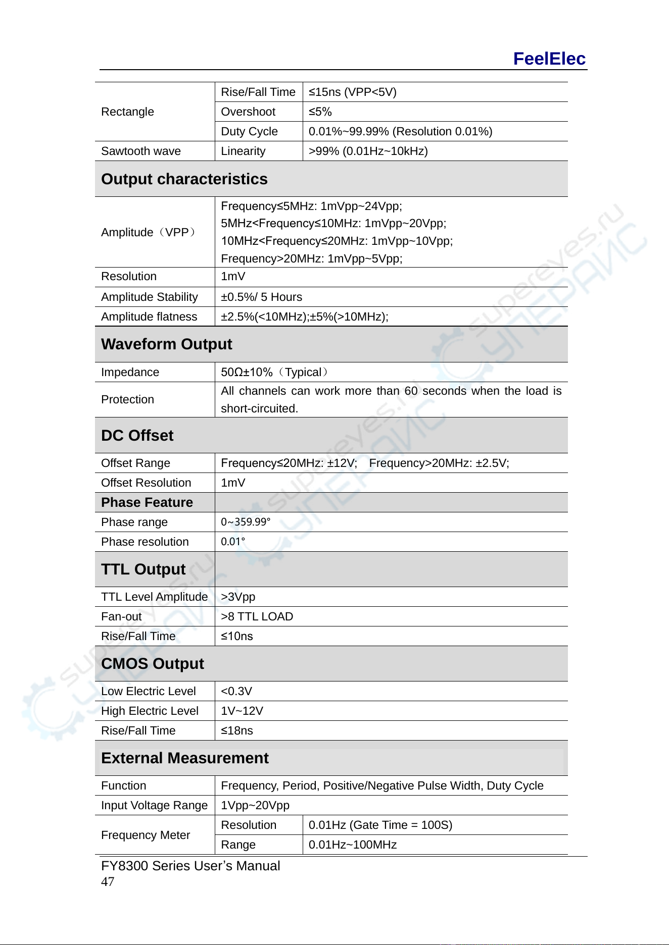
Rectangle
Rise/Fall Time
≤15ns (VPP<5V)
Overshoot
≤5%
Duty Cycle
0.01%~99.99% (Resolution 0.01%)
Sawtooth wave
Linearity
>99% (0.01Hz~10kHz)
Output characteristics
Amplitude(VPP)
Frequency≤5MHz: 1mVpp~24Vpp;
5MHz<Frequency≤10MHz: 1mVpp~20Vpp;
10MHz<Frequency≤20MHz: 1mVpp~10Vpp;
Frequency>20MHz: 1mVpp~5Vpp;
Resolution
1mV
Amplitude Stability
±0.5%/ 5 Hours
Amplitude flatness
±2.5%(<10MHz);±5%(>10MHz);
Waveform Output
Impedance
50Ω±10%(Typical)
Protection
All channels can work more than 60 seconds when the load is
short-circuited.
DC Offset
Offset Range
Frequency≤20MHz: ±12V; Frequency>20MHz: ±2.5V;
Offset Resolution
1mV
Phase Feature
Phase range
0~359.99°
Phase resolution
0.01°
TTL Output
TTL Level Amplitude
>3Vpp
Fan-out
>8 TTL LOAD
Rise/Fall Time
≤10ns
CMOS Output
Low Electric Level
<0.3V
High Electric Level
1V~12V
Rise/Fall Time
≤18ns
External Measurement
Function
Frequency, Period, Positive/Negative Pulse Width, Duty Cycle
Input Voltage Range
1Vpp~20Vpp
Frequency Meter
Resolution
0.01Hz (Gate Time = 100S)
Range
0.01Hz~100MHz
FeelElec
48 FY8300S Series User’s Manual
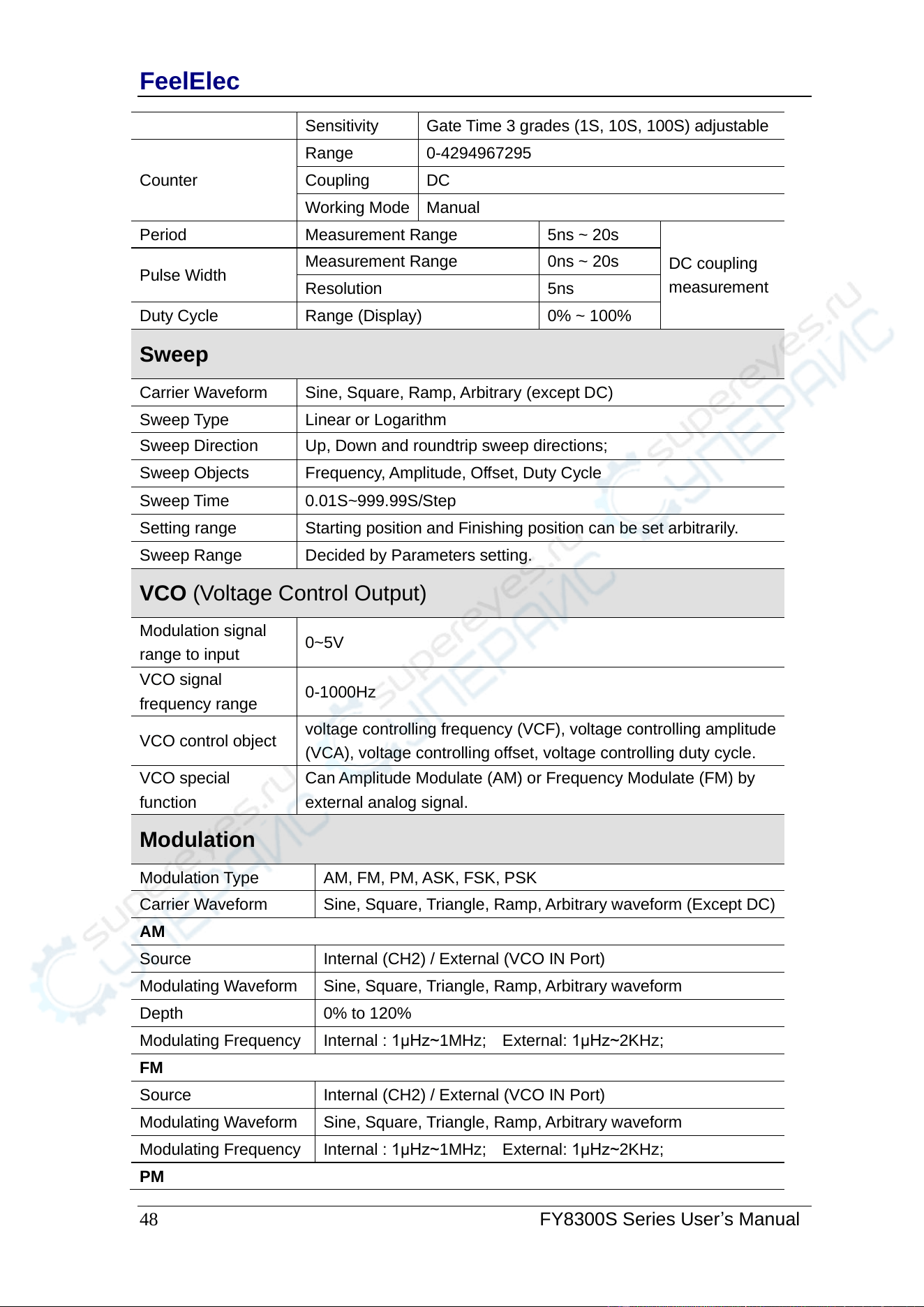
Sensitivity
Gate Time 3 grades (1S, 10S, 100S) adjustable
Counter
Range
0-4294967295
Coupling
DC
Working Mode
Manual
Period
Measurement Range
5ns ~ 20s
DC coupling
measurement
Pulse Width
Measurement Range
0ns ~ 20s
Resolution
5ns
Duty Cycle
Range (Display)
0% ~ 100%
Sweep
Carrier Waveform
Sine, Square, Ramp, Arbitrary (except DC)
Sweep Type
Linear or Logarithm
Sweep Direction
Up, Down and roundtrip sweep directions;
Sweep Objects
Frequency, Amplitude, Offset, Duty Cycle
Sweep Time
0.01S~999.99S/Step
Setting range
Starting position and Finishing position can be set arbitrarily.
Sweep Range
Decided by Parameters setting.
VCO (Voltage Control Output)
Modulation signal
range to input
0~5V
VCO signal
frequency range
0-1000Hz
VCO control object
voltage controlling frequency (VCF), voltage controlling amplitude
(VCA), voltage controlling offset, voltage controlling duty cycle.
VCO special
function
Can Amplitude Modulate (AM) or Frequency Modulate (FM) by
external analog signal.
Modulation
Modulation Type
AM, FM, PM, ASK, FSK, PSK
Carrier Waveform
Sine, Square, Triangle, Ramp, Arbitrary waveform (Except DC)
AM
Source
Internal (CH2) / External (VCO IN Port)
Modulating Waveform
Sine, Square, Triangle, Ramp, Arbitrary waveform
Depth
0% to 120%
Modulating Frequency
Internal : 1μHz~1MHz; External: 1μHz~2KHz;
FM
Source
Internal (CH2) / External (VCO IN Port)
Modulating Waveform
Sine, Square, Triangle, Ramp, Arbitrary waveform
Modulating Frequency
Internal : 1μHz~1MHz; External: 1μHz~2KHz;
PM
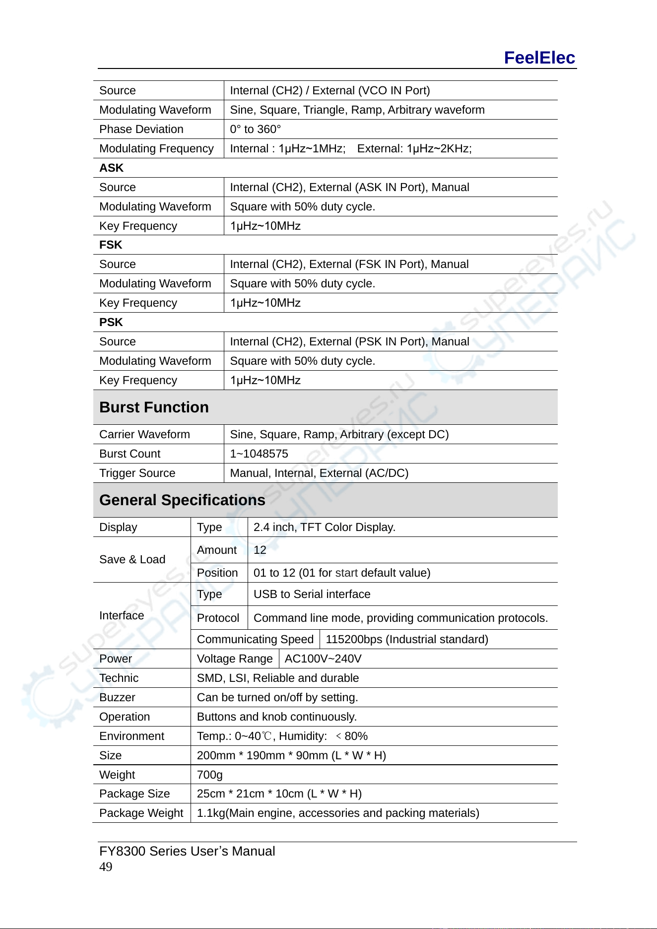
FeelElec
FY8300 Series User’s Manual
49
Source
Internal (CH2) / External (VCO IN Port)
Modulating Waveform
Sine, Square, Triangle, Ramp, Arbitrary waveform
Phase Deviation
0° to 360°
Modulating Frequency
Internal : 1μHz~1MHz; External: 1μHz~2KHz;
ASK
Source
Internal (CH2), External (ASK IN Port), Manual
Modulating Waveform
Square with 50% duty cycle.
Key Frequency
1μHz~10MHz
FSK
Source
Internal (CH2), External (FSK IN Port), Manual
Modulating Waveform
Square with 50% duty cycle.
Key Frequency
1μHz~10MHz
PSK
Source
Internal (CH2), External (PSK IN Port), Manual
Modulating Waveform
Square with 50% duty cycle.
Key Frequency
1μHz~10MHz
Burst Function
Carrier Waveform
Sine, Square, Ramp, Arbitrary (except DC)
Burst Count
1~1048575
Trigger Source
Manual, Internal, External (AC/DC)
General Specifications
Display
Type
2.4 inch, TFT Color Display.
Save & Load
Amount
12
Position
01 to 12 (01 for start default value)
Interface
Type
USB to Serial interface
Protocol
Command line mode, providing communication protocols.
Communicating Speed
115200bps (Industrial standard)
Power
Voltage Range
AC100V~240V
Technic
SMD, LSI, Reliable and durable
Buzzer
Can be turned on/off by setting.
Operation
Buttons and knob continuously.
Environment
Temp.: 0~40℃, Humidity: ﹤80%
Size
200mm * 190mm * 90mm (L * W * H)
Weight
700g
Package Size
25cm * 21cm * 10cm (L * W * H)
Package Weight
1.1kg(Main engine, accessories and packing materials)
FeelElec
50 FY8300S Series User’s Manual
Appendix
Appendix A:Safety Notes
1. Before using this instrument, please check if the power supply is normal, to
ensure the normal use and personal safety.
2. This instrument must be used in the technical index range.
3. Please do not change the instrument circuit arbitrarily, so as to avoid damaging
equipment or endangering the safety.
Appendix B:Warning and personal injury
Do not apply the product in the safety protection device or emergency stop
device, or any other applications that the product failure could result in personal
injury, unless there is special purpose or use authorization. Before the installation
and use, each parameter of the technical indexes in this manual should be
referred to. If this suggestion is not obeyed, death or serious personal injury could
be caused. In this condition the company will not be responsible for any
compensation of personal injury or death, and all the company managers and
employees and auxiliary agents, distributors, other personnel concerned will be
released from any claim (including all the costs, expenses, attorney fees etc.) that
may result in.
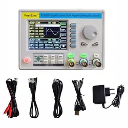
Appendix C:Accessories and Options
Description
Quantity
Model
FY8300S Series DDS Signal Generator
1
Standard
Accessories
Power Cable
1
USB Data Cable
1
BNC-Clip Cable
3
BNC-BNC Cable
1
Warranty Card
1
Options
FYA2000 Series Amplifier
FPA2000 Series Amplifier
Note: Options can be ordered from local FeelElec distributors.
Appendix D:Warranty
FeelElec warrants that its products mainframe and accessories will be free
from defects in materials and workmanship within the warranty period. If a
product is proven to be defective within the respective period, FeelElec
guarantees the free replacement or repair of products which are approved
defective. This product enjoy 1 year warranty since its delivery. Damages caused
by misuse, vandalism, improper maintenance or force majeure are not covered by
the warranty. Any disassembly or amendment without permission will be deemed
giving up warranty rights consciously.