
BULLETIN NO.
54-07-3605
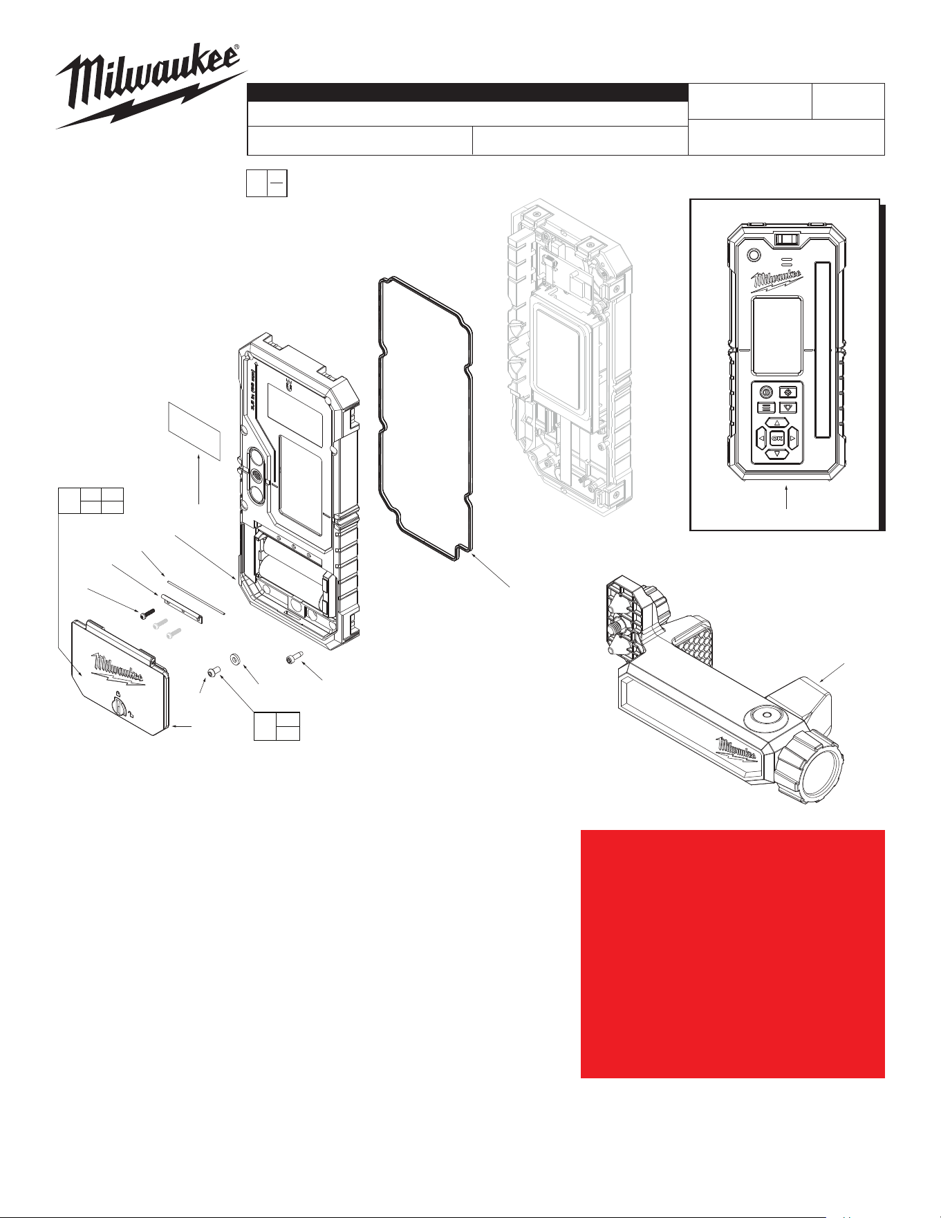
SERVICE PARTS LIST
FIG. PART NO. DESCRIPTION OF PART NO. REQ.
17 43-44-0614 Main Gasket/Combo (1)
19 05-74-0755 M2.5 x 8mm Pan Head T6 Screw (8)
21 31-21-0048 Power Cell Door Hinge (1)
22 31-21-0049 Power Cell Door Pin (1)
23 05-74-0754 M2 x 8mm Pan Head T6 ST Screw (3)
31 05-74-0761 M3x5mm Pan Head H2 ST Screw (1)
32 43-44-0613 Leak Test Gasket/ ID=3mm T=1.2mm (1)
46 12-20-0304 Service Nameplate (1)
54 31-21-0046 Power Cell Door Kit/Combo (1)
55 31-21-0047 Power Cell Door Assembly / Combo (1)
57 31-50-0197 Bottom Housing Assembly / Combo (1)
58 43-44-0612 Leak Test Gasket Kit (1)
60 22-38-0106 Rotary Detector Clamp Assembly (1)
61 3712
1000' Rotary Combo Remote/Detector
(1)
CATALOG NO. 3712
REVISED BULLETIN
SPECIFY CATALOG NO. AND SERIAL NO. WHEN ORDERING PARTS
Green Interior Rotary Laser Remote Control & Receiver
DATE
July 2023
WIRING INSTRUCTION
M98A
0
00
EXAMPLE:
Component Parts (Small #)
Are Included When Ordering
The Assembly (Large #).
FIG. NOTES
46 A clean, dry surface is essential for proper performance for any
adhesive system. The area intended for application of any adhesive
label or nameplate must be prepared by cleaning with isopropyl
alcohol. The solvent is to be applied with a clean, lint free applicator
and the surface allowed to dry before applying the label or name
plate.
55
23
(x3)
21
22
57
19
(x8)
31
32
46
21 22
23 55
54
31
32
58
17
61
MILWAUKEE TOOL
l
www.milwaukeetool.com
13135 W. LISBON RD., BROOKFIELD, WI 53005
Drwg. 1
Service needs pertaining to accuracy
or calibration can only be performed at
MILWAUKEE TOOL Central Repair:
1401 Sycamore Ave. Greenwood, MS 38930-7277
OR
2198 Southtech Drive Greenwood, IN 46143-6725
OR Via e-Service at:
www.milwaukeetool.com/e-service.
QUESTIONS: please call 1.800.SAWDUST
OR
Return it to a MILWAUKEE FACTORY SERVICE
CENTER location, freight prepaid and insured.
A copy of the proof of purchase should be
included with the return product.
60
SERIAL NO.
9
8
11
10
(x2)
8 9
10 11
53
15
51
15
52
15
(x4)
56
59
(x4)
14
(x5)
12
14
(x2)
13
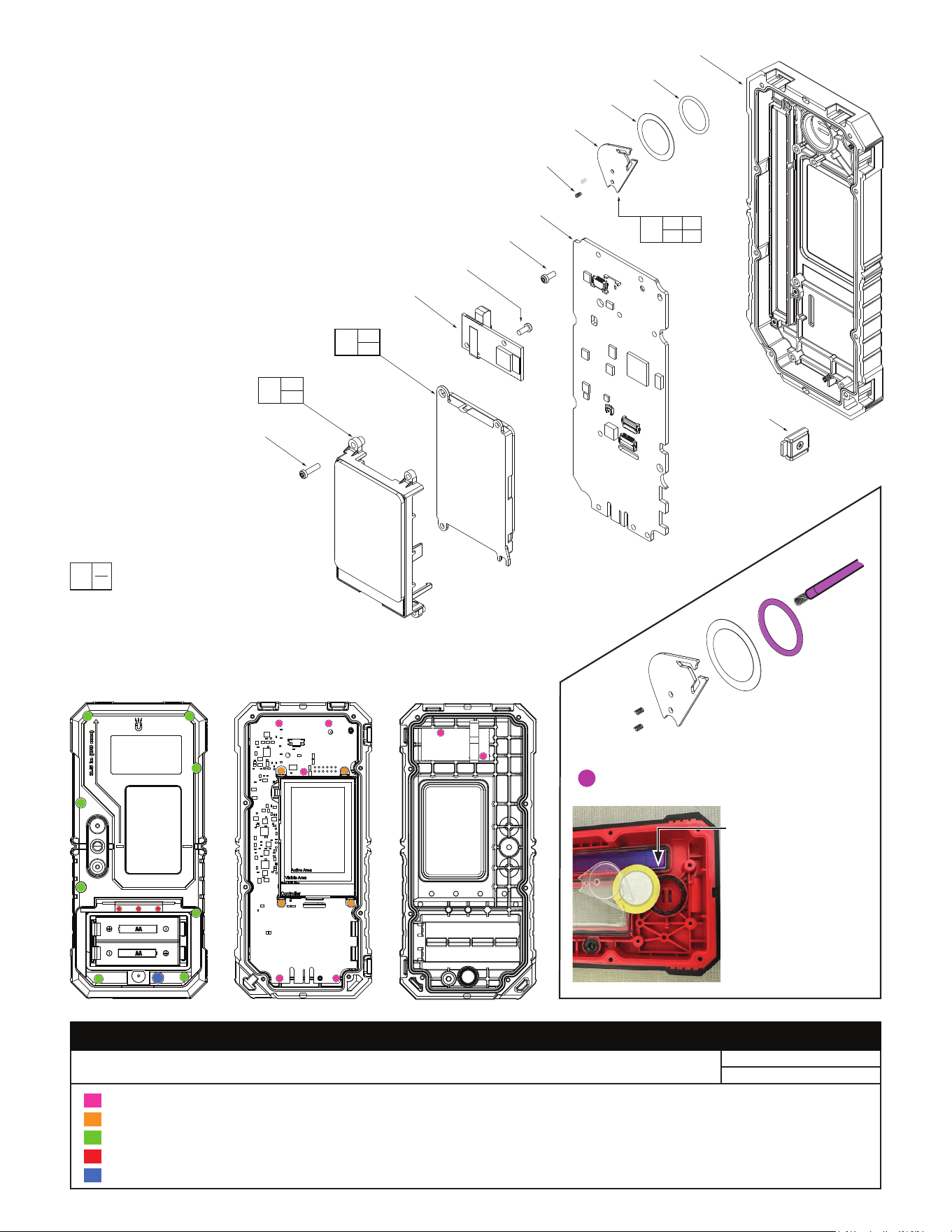
FIG. PART NO. DESCRIPTION OF PART NO. REQ.
8 --------------- Buzzer O-Ring (1)
9 --------------- Piezo Buzzer (1)
10 --------------- Buzzer Spring (2)
11 --------------- PiezoBuzzerStando (1)
12 --------------- PCBA (1)
13 --------------- BLE Module (1)
14 05-74-0762 M2.5 x 6mm Pan Head T8 ST Screw (7)
15 05-74-0753 M2.5 x 10mm Pan Head T8 ST Screw (4)
51 44-06-0116 Front LCD Kit / Combo (1)
52 44-06-0117 Rear LCD Kit / Combo (1)
53 14-46-0363 Piezo Buzzer Kit (1)
56 31-50-0196 Top Housing Assembly/Combo (1)
59 23-27-0015 Magnet Assembly / Combo (4)
0
00
EXAMPLE:
Component Parts (Small #)
Are Included When Ordering
The Assembly (Large #).
SCREW TORQUE SPECIFICATIONS
SEAT TORQUE
FIG. PART NO. DESCRIPTION OF FASTENER WHERE USED (kgf-cm) (lb-in)
14 05-74-0762 M2.5 x 6mm Pan Head T8 ST Screw PCBA and Front Housing; BLE Module 4.0 ± 0.5 3.5 ± 0.4
15 05-74-0753 M2.5 x 10mm Pan Head T8 ST Screw LCD Holders and Front Housing 4.0 ± 0.5 3.5 ± 0.4
19 05-74-0755 M2.5 x 8mm Pan Head T6 Screw Front and Rear Housings 5.0 ± 0.5 4.3 ± 0.4
23 05-74-0754 M2 x 8mm Pan Head T6 ST Screw Rear Housing and Power Cell Door 3.5 ± 0.5 3.0 ± 0.4
31 05-74-0761 M3 x 5mm Pan Head H2 ST Screw Rear Housing 4.0 ± 0.5 3.5 ± 0.4
NOTE: The picture to
the left may not rep-
resent the tool above,
but the lubrication
instruction is still valid.
Coat the O-Ring (#8) with
a thin layer of grease on
all sides of the O-Ring.
Check and remove any
excess grease from the
buzzer cavity walls.
LUBRICATION:
= Type "H042" Grease, 50-08-5317