User Manual


Table of Contents
2023-06 EN 5040064.10A.04
3
Table of Contents
1 IMPORTANT SAFETY INSTRUCTIONS .................. 5
Important Information ........................................ 7
2 My bernette Overlocker ...................................... 9
2.1 Machine Overview .................................................. 9
Front view ................................................................... 9
Overview - Needle area ............................................... 10
Overview Presser Foot ................................................. 11
Overview - Looper area ............................................... 12
Overview Threading area ............................................. 13
Overview - Side panel .................................................. 14
Symbols ...................................................................... 15
2.2 Overview - Standard Accessories ............................. 16
Included accessories .................................................... 16
Accessories behind the Threader Cover ....................... 17
Accessories Box ........................................................... 18
3 Setting Up the Machine ...................................... 20
3.1 Working Area ......................................................... 20
3.2 Connection and Switching On ................................ 20
Connecting the Machine and Foot Control .................. 20
Switching the Machine and Sewing Light On/Off ........ 21
3.3 Foot Control ........................................................... 21
Press the Foot Control ................................................. 21
3.4 Handwheel ............................................................. 21
3.5 Machine Covers ...................................................... 22
Open/Close the Threader Cover .................................. 22
3.6 Spool Holder ........................................................... 22
Attaching the Spool Holder ......................................... 22
Preparing the Thread Guide ........................................ 23
Attaching the Spool Stabilizer ..................................... 23
Place the Spool Disc .................................................... 24
Using the Spool Net .................................................... 24
3.7 Presser Foot ............................................................ 25
Positioning the Presser Foot Up/Down ......................... 25
Lifting the Presser Foot Up/Down with the Knee Lifter . 25
Changing the Presser Foot .......................................... 26
3.8 Needle Area ............................................................ 27
Needle Holder ............................................................. 27
Changing the needle ................................................... 27
Threading the Needle Manually ................................... 29
Positioning the Needles Up/Down ............................... 29
3.9 Sewing Assistance ................................................. 30
Using the Thread Cutter ............................................. 30
Attaching/Removing the Knee Llifter ........................... 30
Attaching/Removing the Cut-offs Bin .......................... 31
Attaching/Removing the Freearm Cover ...................... 31
Attaching/removing the Slide-on Table ....................... 32
Attaching the Decorative Threads Guide ..................... 32
4 Sewing Start ........................................................ 33
4.1 Check before starting to sew ................................. 33
4.2 Selecting the Fabric ................................................ 33
4.3 Selecting the Thread .............................................. 33
Needle Thread ............................................................ 34
Looper Thread ............................................................ 34
4.4 Selecting the Needle .............................................. 35
Detect Defective Needles ............................................ 36
Needle Overview ........................................................ 36
4.5 Fixing Fabric Layers ................................................ 36
5 Stitch .................................................................... 37
5.1 Stitch Type ............................................................. 37
Overlock Stitch ........................................................... 37
Select stitch by application .......................................... 38
5.2 Stitch Chart ........................................................... 41
6 Machine Settings ................................................ 43
6.1 Setting the Knife .................................................... 43
Knife On/Off ............................................................... 43
Setting the Cutting Width .......................................... 44
6.2 Upper Looper Converter Hooked in/Hooked out .... 45
6.3 Rolled Hem Selection Lever «N/R» .......................... 46
Overlocking «N» ......................................................... 46
Rolled hem «R» .......................................................... 46
6.4 Setting the mtc micro thread control ..................... 47
6.5 Setting the Presser Foot Pressure ............................ 48
6.6 Adjusting the Stitch Width ..................................... 48
Changing the stitch width via the needle position ....... 48
Changing the stitch width via the Cutting Width ........ 48
6.7 Adjusting the thread tension .................................. 49
6.8 Adjusting the Differential Feed ............................... 49
Default Value "1" ...................................................... 50
Gathering/Gather to fit "1.5 – 2" ............................... 50

Table of Contents
4
2023-06 EN 5040064.10A.04
Stretching "0.6" ......................................................... 51
6.9 Setting the Stitch Length ........................................ 52
7 Threading ............................................................. 53
7.1 Threading preparation ............................................ 53
7.2 Air Threader ........................................................... 54
Threading the Looper Threads UL/blue, LL/red ............. 55
Threading the Looper Thread with an auxiliary thread . 57
Using the Threading Wire ............................................ 57
7.3 Threading the needle thread ................................... 58
Threading the Right Needle Thread RN/green .............. 58
Threading the Left Needle Thread LN/yellow ................ 59
7.4 Thread change ........................................................ 60
Knotting thick thread .................................................. 60
Changing the needle thread ........................................ 61
Changing the looper thread ........................................ 61
8 Sewing Test .......................................................... 62
8.1 Perfoming a Sewing Test for an Overlock Stitch ...... 62
8.2 Optimizing stitches ................................................. 62
4-/3-thread Overlock ................................................... 63
3-Thread Narrow Seam ............................................... 64
3-thread super-stretch / 2-thread wrapped overlock .... 65
3-thread flatlock ......................................................... 66
3-thread rolled hem / 3-thread picot stitch .................. 67
2-thread rolled hem .................................................... 68
2-thread flatlock / 2-thread overlock ........................... 69
9 Practical Overlocking ........................................... 70
9.1 Securing Overlock Stitches ...................................... 70
Sewing in the Overlock Chain at the Start of the Seam 70
Sewing in the Overlock Chain at the End of the Seam . 70
Securing Overlock Stitches .......................................... 71
Knotting the Overlock chain ........................................ 71
9.2 Removing a Stitch ................................................... 71
9.3 Flatlock ................................................................... 72
9.4 Gathering ............................................................... 73
Increasing the differential feed .................................... 73
Pulling the Needle Thread ........................................... 73
9.5 Sew Outer Corners ................................................. 74
9.6 Sewing Inner Corners ............................................. 75
9.7 Sewing Inner Curves ............................................... 75
9.8 Sew Outer Curves and Circles ................................. 76
10 Appendix .............................................................. 77
10.1 Storing and Transporting the Machine .................... 77
Storing the Machine .................................................... 77
Transporting the Machine ........................................... 77
10.2 Maintenance and Cleaning the Machine ................ 77
Cleaning the Machine ................................................ 77
Cleaning the Looper Area ........................................... 78
Cleaning the air threader pipes ................................... 79
Cleaning the Suction Feet ........................................... 79
Oiling the Machine ..................................................... 80
10.3 Troubleshooting .................................................... 81
10.4 Specifications ......................................................... 82

IMPORTANT SAFETY INSTRUCTIONS
5
2023-06 EN 5040064.10A.04
IMPORTANT SAFETY INSTRUCTIONS
Please be aware of the following basic safety instructions when using your
machine. Before using this machine, read instruction manual carefully.
DANGER!
To reduce the risk of electrical shock:
• Never leave the machine unattended as long as it is plugged in.
• Always unplug the machine from the electrical outlet immediately after
using and before cleaning.
Protection against LED radiation:
• Do not view the LED light directly with optical instruments (e.g. magnifier).
The LED light corresponds with protection class 1M.
• When the LED light is damaged or defective, contact your bernette specialist
dealer.
To reduce the risk of injury:
• Caution: moving parts. To reduce risk of injury, switch the machine off
before servicing. Close the covers before operating machine.
WARNING
To reduce the risk of burns, fire, electric shock or injury to persons:
• To operate the machine always use the supplied power cable. USA and
Canada only: Do not connect power plug NEMA 1-15 to circuits exceeding
150 volt-to-ground.
• This machine may only be used for the purpose described in this instruction
manual.
• Only use the machine in dry rooms.
• Do not use the machine in a damp condition or in a damp environment.
• Do not use the machine as a toy. You must take extra care if the machine is
being used by children or in the vicinity of children.
• This machine may be used by children eight years of age and older as well as
persons with restricted physical, sensory or mental capacities or lack of
experience and knowledge under supervision or having received instruction
on the safe use of the machine and the resulting hazards.
• Children must not play with the machine.
• Cleaning and maintenance work must not be carried out by children without
supervision.

IMPORTANT SAFETY INSTRUCTIONS
6
2023-06 EN 5040064.10A.04
• Do not use this machine if the cable or plug is damaged, the machine is not
functioning correctly, it is dropped or becomes damaged or falls in water.
Never operate this machine if it has a damaged cord or plug, if it is not
working properly, if it has been dropped or damaged, or dropped into
water. Contact the nearest authorized bernette dealer to arrange further
details.
• Only use accessories recommended by the manufacturer.
• Do not use this machine if the ventilation openings are blocked. Keep all
ventilation openings and foot control free of lint, dust and loose cloth.
• Do not insert any objects into the openings of the machine.
• Do not place any objects on the foot control.
• Always use the machine with a foot control of this type .
• Do not use the machine anywhere that oxygen or propellant products
(sprays) are being used.
• The knife cover insert or coverstitch insert must be attached continuously
while operating the machine.
• Keep fingers away from all rotating and moving parts. Special care is
required in the needle area, the looper and the knife.
• Neither pull nor push the fabric while sewing. This can cause needle
breakage.
• Turn power switch to «0» when making any adjustments in the needle area,
such as threading the needle or changing the needle or the presser foot.
• Never use damaged needles.
• Always use the original bernette stitch plate. The wrong stitch plate can
cause needle breakage.
• To disconnect, turn power switch to "0"and then remove the plug from the
outlet. Always pull on the plug and not the cable.
• Disconnect the plug before removing or opening the covers, oiling the
machine or performing any cleaning or maintenance work described in this
instruction manual.
• This machine is double-insulated (except for USA, Canada and Japan). Use
only genuine replacement parts. See instructions for Servicing of double-
insulated products.

Important Information
7
2023-06 EN 5040064.10A.04
Important Information
Availability of the Instruction Manual
The short manual is part of the machine.
• Keep the short manual of the machine in a suitable place near the machine and have it ready for
reference.
• The latest version of the detailed instruction manual can be downloaded at www.mybernette.com.
• When passing on the machine to a third party, enclose the short manual of the machine.
Proper Use
Your bernette machine is conceived and designed for private household use. It answers the purpose for
overlocking fabrics as it is decribed in this instruction manual. Any other use is not considered proper.
BERNINA assumes no liability for consequences resulting from improper use.
Equipment and Scope of Delivery
Example images are used in these instructions for the purposes of illustration. The machines shown in the
images and the accessories shown therefore do not always match the actual items included with your
machine. The supplied accessory can vary depending on the country of delivery. You can acquire any
accessories mentioned or shown that are not included in the scope of delivery as optional accessories from a
specialist bernette dealer. Further accessories can be found at www.mybernette.com.
For technical reasons and in order to improve the product, changes may be made to the equipment of the
machine and the scope of delivery at any time and without prior notice.
Servicing of Double-insulated Products
In a double-insulated product two systems of insulation are provided instead of grounding. No grounding
means is provided on a double-insulated product nor should a means for grounded be added to the product.
Servicing a double-insulated product requires extreme care and knowledge of the system and should only be
done by qualified service personnel. Replacement parts for a double-insulated product must be identical to
the original parts in the product. A double insulated product is marked with the words: «Double-Insulation»
or «double-insulated».
The symbol may also be marked on the product.
Environmental Protection
BERNINA International AG is committed to environmental protection. We strive to minimize the
environmental impact of our products by continuously improving product design and our technology of
manufacturing.
The machine is labeled with the symbol of the crossed-out wastebin. This means that the machine should
not be disposed of in household waste when it is no longer needed. Improper disposal can result in
dangerous substances getting into the groundwater and thus into our food chain, damaging our health.
The machine must be returned free of charge to a nearby collection point for waste electrical and electronic
equipment or to a collection point for the reuse of the machine. Information on the collection points can be
obtained from your local administration. When purchasing a new machine, the dealer is obliged to take back
the old machine free of charge and dispose of it properly.
If the machine contains personal data, you are responsible for deleting the data yourself before returning the
machine.

Important Information
8
2023-06 EN 5040064.10A.04
Explanation of Symbols
DANGER
Designates a high-risk hazard which can lead to serious injuries or potentially even death if not avoided.
WARNING
Designates a medium-risk hazard which can lead to serious injuries if not avoided.
CAUTION
Designates a low-risk hazard which can lead to minor or moderate injuries if not avoided.
NOTICE
Designates a hazard which can lead to material damage if not avoided.
You will find tips from bernette sewing experts next to this symbol.
My bernette Overlocker
9
2023-06 EN 5040064.10A.04
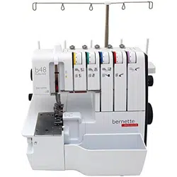
2 My bernette Overlocker
2.1 Machine Overview
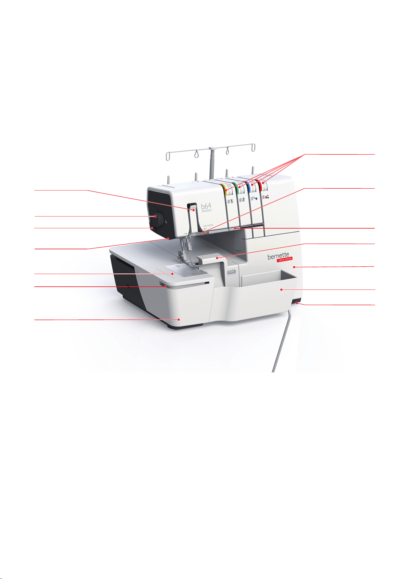
Front view
1
2
3
5
6
7
8
10
12
13
4
9
11
14
1 Freearm Cover 8 Thread Tension Adjustment
2 Guide Rail 9 Thread Deflection Fingers
3 Freearm 10 Thread Guiding Plate
4 Sewing Light (LED) 11 Knife Cover Insert
5 Thread Cutter 12 Threader Cover
6 Presser Foot Presser Wheel 13 Cut-offs Bin
7 Needle Thread Take-up Lever Cover 14 Suction Feet
My bernette Overlocker
10
2023-06 EN 5040064.10A.04
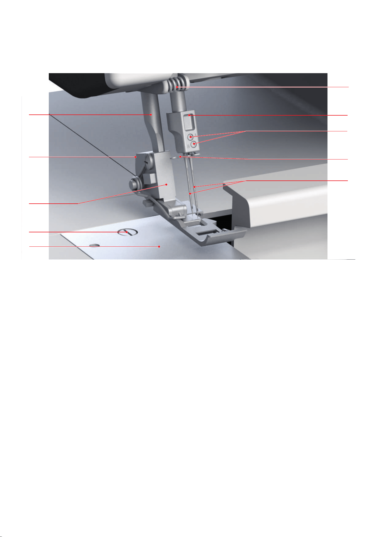
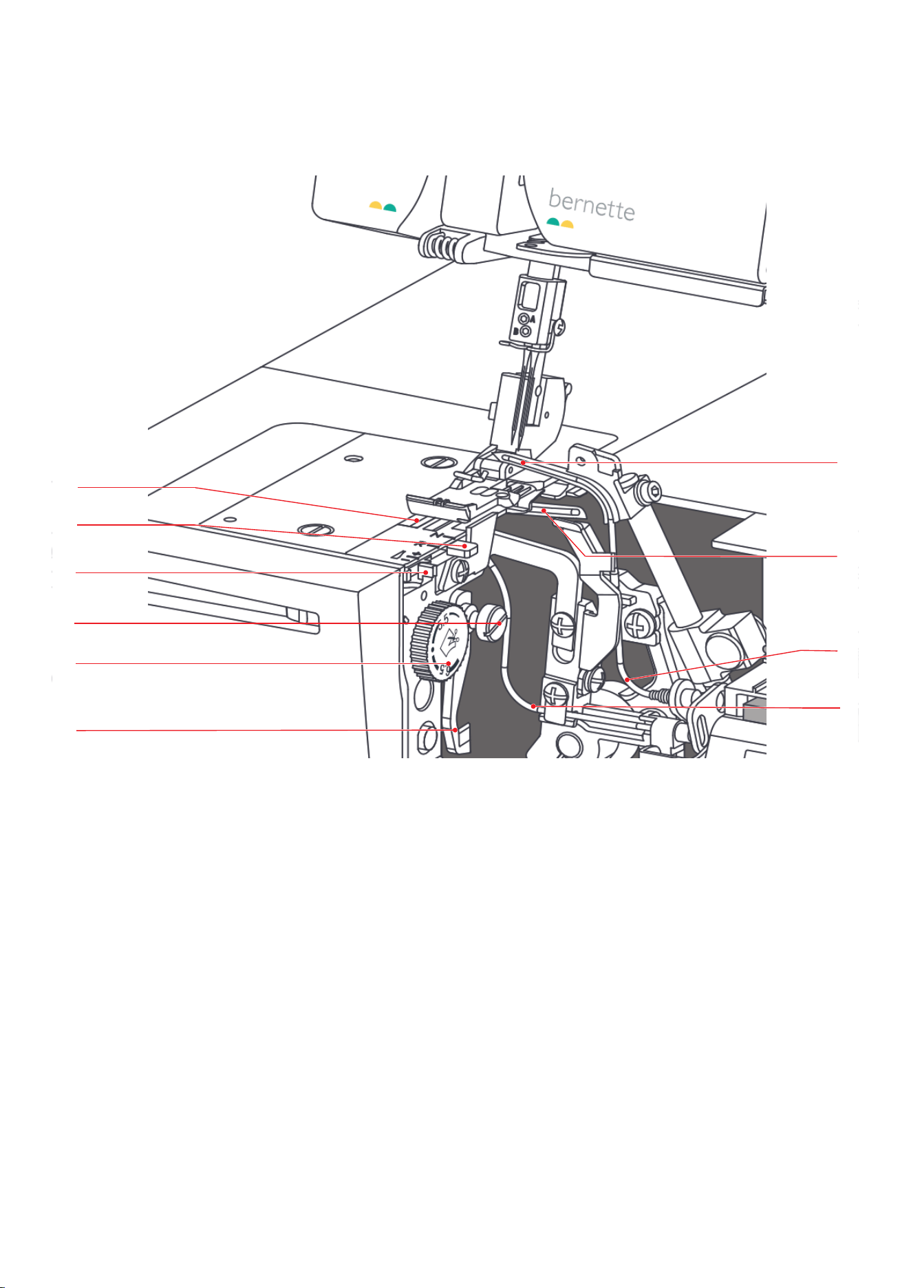
Overview - Needle area
1
2
4
5
3
7
9
10
8
6
1 Stitch Plate 6 Thread Guide on the Headframe
2 Stitch Plate Screw 7 Needle Holder
3 Standard Overlock Presser Foot 8 Needle Screws
4 Presser Foot Release Lever (red) 9 Thread Guide on the Needle Holder
5 Presser Foot Bar 10 Needles ELx705
My bernette Overlocker
11
2023-06 EN 5040064.10A.04
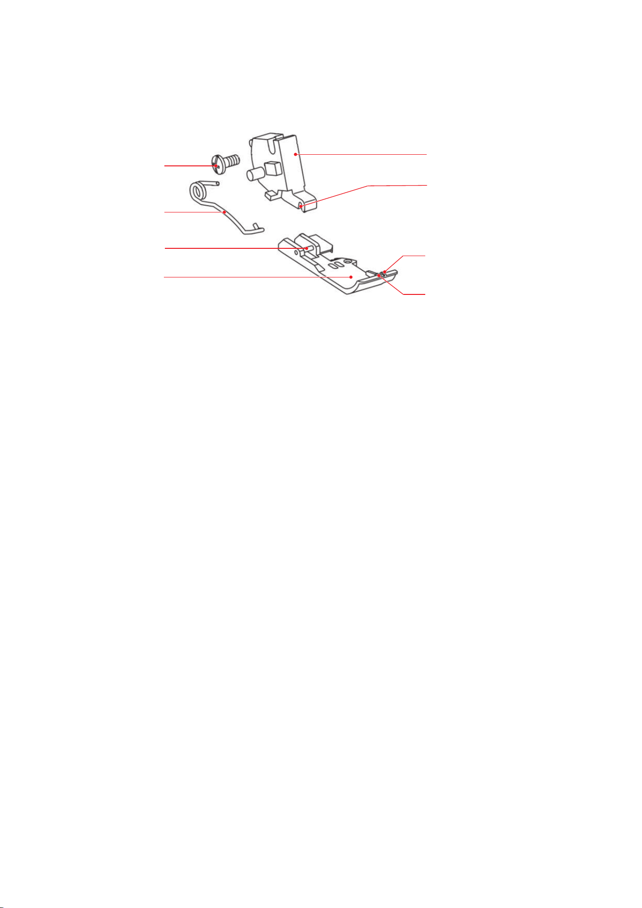
Overview Presser Foot
1
2
3
4
5
6
7
8
1 Presser Foot Sole 5 Presser Foot Shaft
2 Presser Foot Sole Pin 6 Shaft groove
3 Presser Foot Spring 7 Right Needle position (RN)
4 Fixing screw 8 Left Needle position (LN)
My bernette Overlocker
12
2023-06 EN 5040064.10A.04
Overview - Looper area
2
4
7
8
10
9
5
1
3
6
1 Knife 6 Feed Dog
2 Cutting Width Dial 7 Upper Looper
3 Knife On/Off 8 Lower Looper
4 mtc Micro Thread Control Dial 9 Upper Looper Air Threader Pipe
5 Rolled Hem Selection Lever 10 Air Threader Duct Lower Looper
My bernette Overlocker
13
2023-06 EN 5040064.10A.04
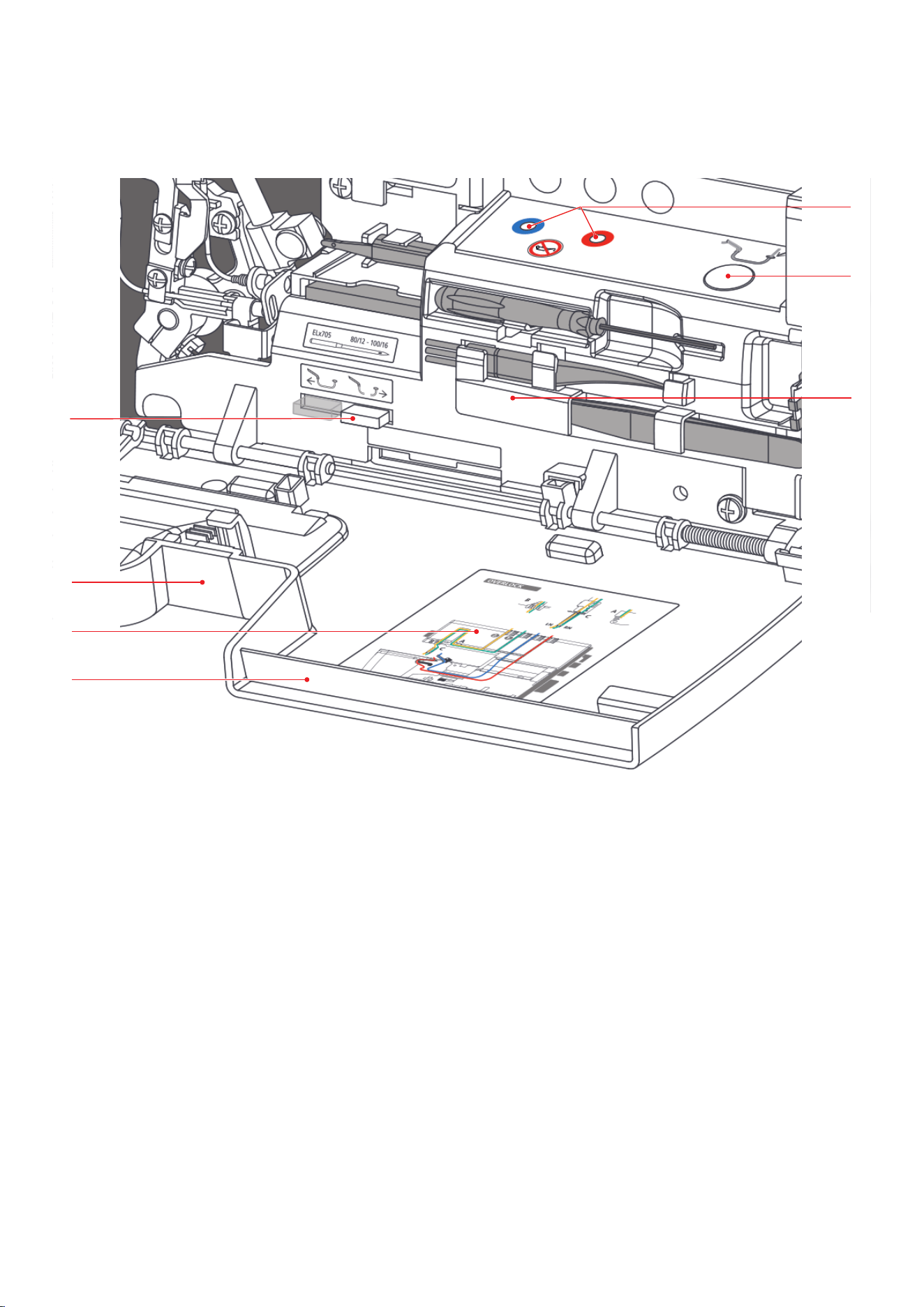
Overview Threading area
1
2
3
4
5
6
7
1 Threader Cover 5 Air Threader Nozzles
2 Threading Chart 6 Air Threader Lever
3 Knife Cover Insert 7 Accessories in the Threader Cover
4 Air Threader Connector On/Off
My bernette Overlocker
14
2023-06 EN 5040064.10A.04
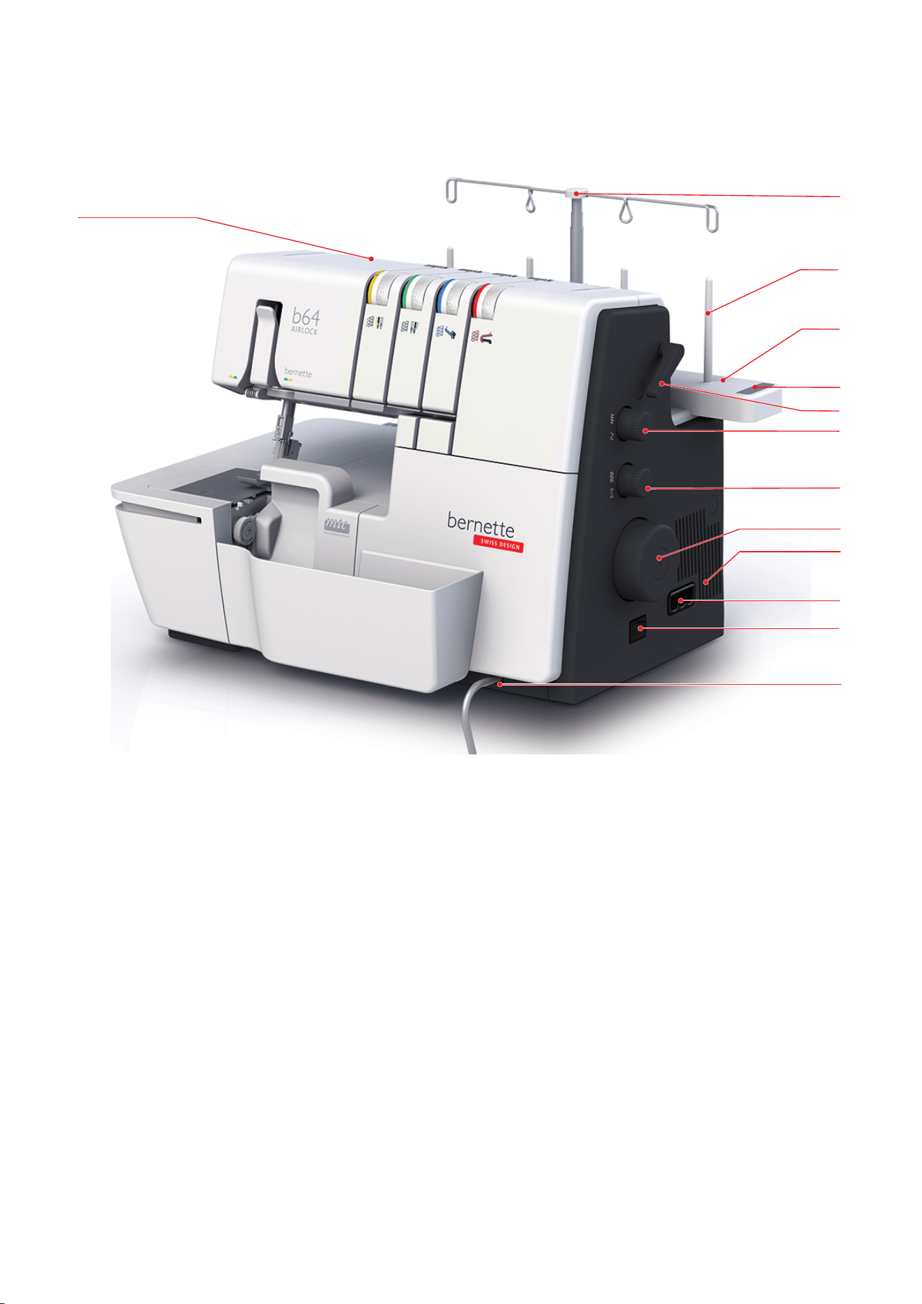
Overview - Side panel
11
12
9
8
7
2
6
5
10
4
1
3
13
1 Carry Handle 8 Differential Feed Dial
2 Retractable Thread Guide 9 Handwheel
3 Spool Pin 10 Air Vents
4 Spool Pin 11 Foot control-/ power connection
5 Needle Pad 12 Power Switch
6 Presser Foot Lifter 13 Connection for Knee Lifter (FHS)
7 Stitch Length Setting
My bernette Overlocker
15
2023-06 EN 5040064.10A.04
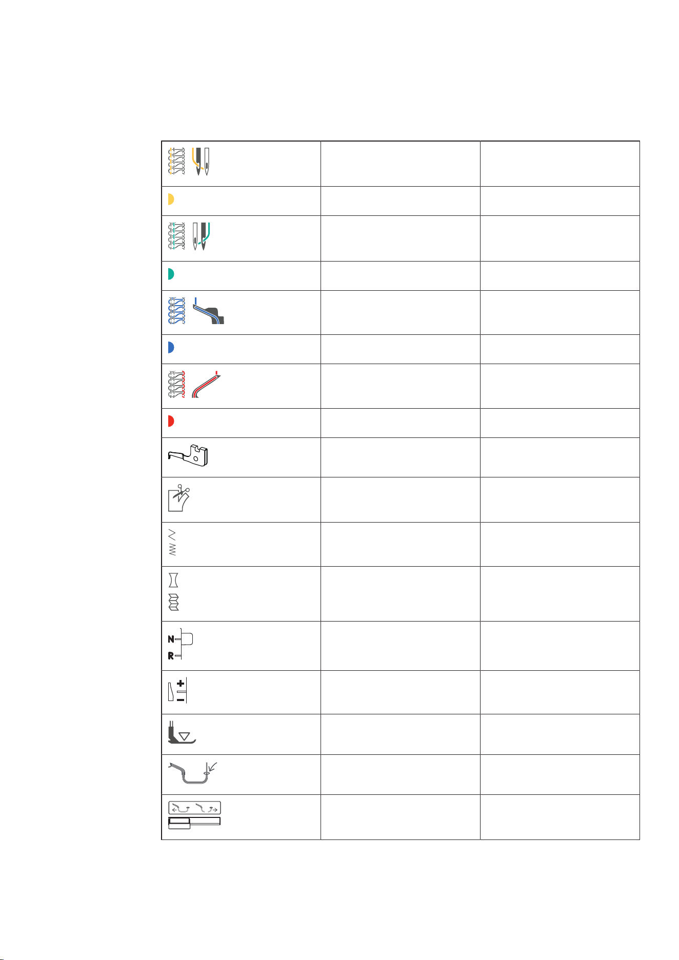
Symbols
The symbols are for your guidance and give assistance when adjusting settings and threading the machine.
LN Left Needle Thread
Thread path yellow
RN Right Needle Thread
Thread path green
UL Upper Looper Thread
Thread path blue
LL Lower Looper Thread
Thread path red
ULC Upper Looper Converter
CW Cutting Width
SL Stitch Length
DF Differential Feed
N/R Rolled Hem Selection Lever
mtc mtc Micro Thread Control
Presser Foot Pressure
Air Threader Lever
Air Threader Connector On/Off
My bernette Overlocker
16
2023-06 EN 5040064.10A.04
2.2 Overview - Standard Accessories
Included accessories
Visit www.mybernette.comfor more accessories information.
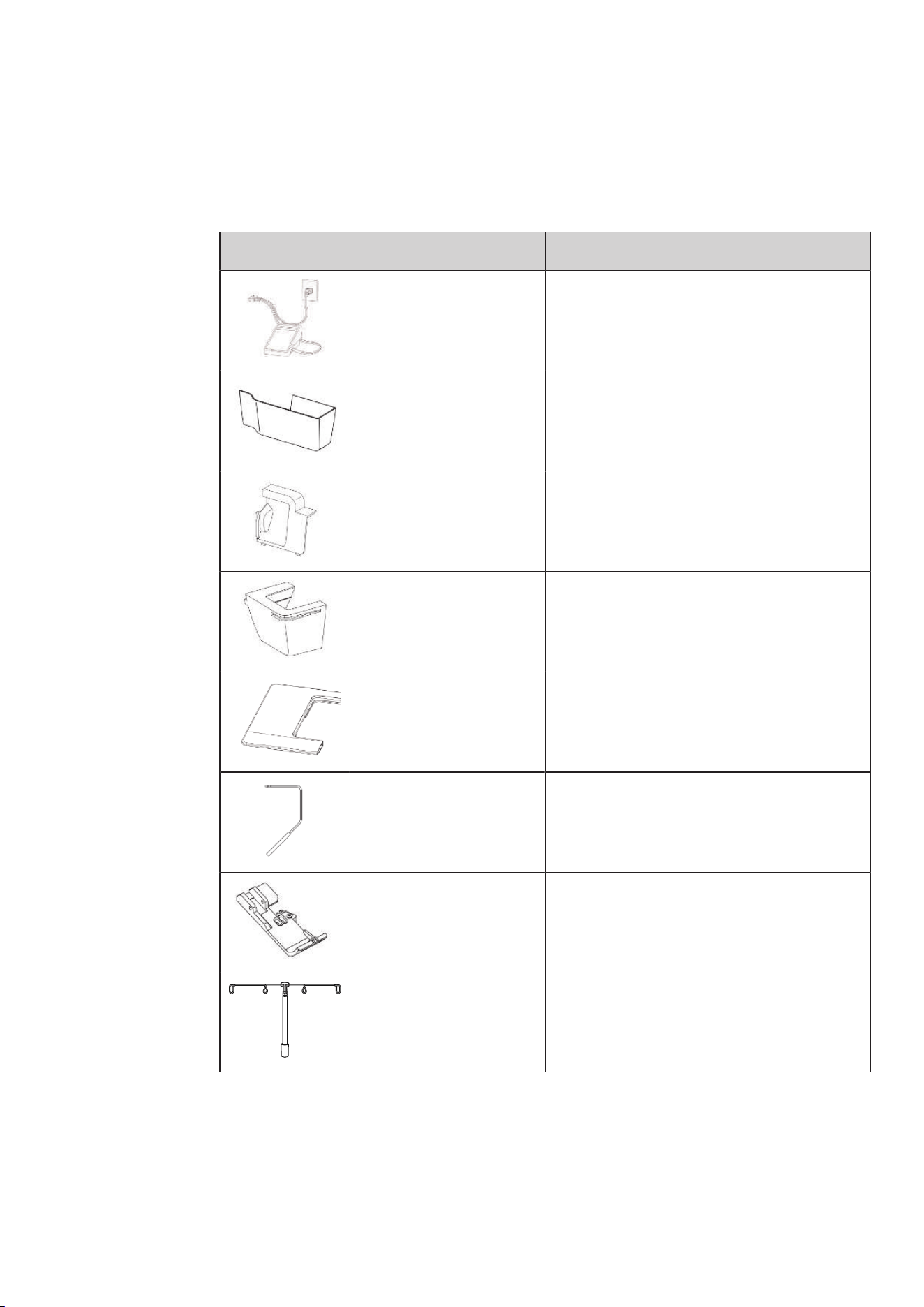
Illustration Name Purpose
Power Cable and Foot
Control Cable
To connect the machine with the power supply
system and the Foot Control.
Cut-Offs Bin To collect resulting scraps.
Knife Cover Insert To protect the fingers and to deflect the fabric cut-
offs during the sewing process.
Freearm Cover To extend the work surface.
Slide-on Table To increase the sewing surface.
Free Hand System (FHS) To raise and lower the presser foot.
Overlock Foot For all overlock stitches.
For general sewing projects.
Retractable Thread Guide For an even unwinding of the thread from the
thread cones.
My bernette Overlocker
17
2023-06 EN 5040064.10A.04
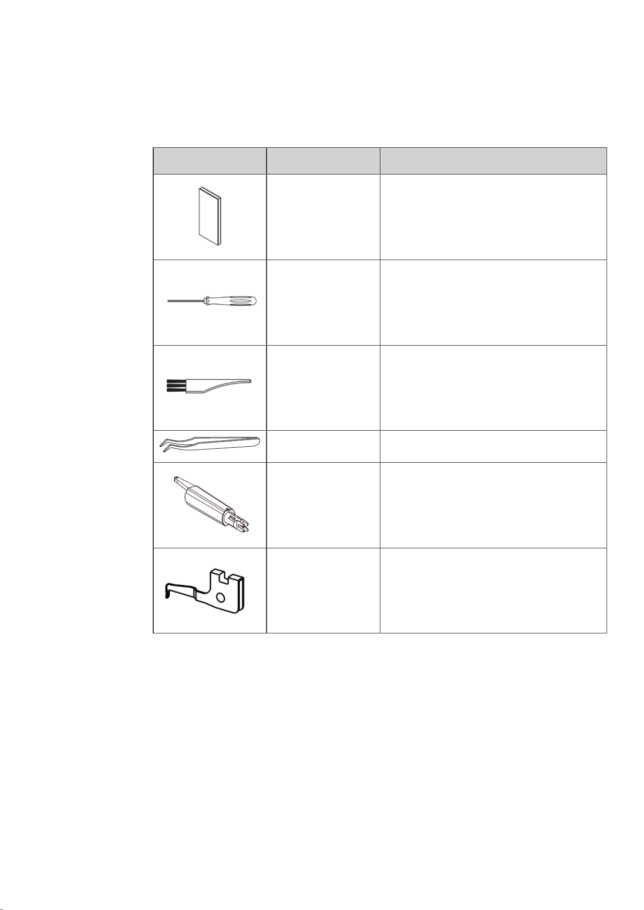
Accessories behind the Threader Cover
The most often used accessories while sewing are stored behind the Threader Cover on the machine, so it is
always quickly at hand.
Illustration Name Purpose
Needle Set ELx705 CF
(3xNo.80, 2xNo.90)
For the most frequently used Overlock applications,
in various needle sizes.
Screwdriver To loosen or tighten the fixing screws on the
needle holder.
Brush To clean the feed dog and the looper area.
BERNINA Tweezers For gripping the thread in tight positions.
Needle Threader/
Inserter
To manually thread, insert and remove the needle.
Upper Looper Converter To cover the Upper Looper.
For sewing 2-thread overlock and the 3-thread
super-stretch stitch.
My bernette Overlocker
18
2023-06 EN 5040064.10A.04
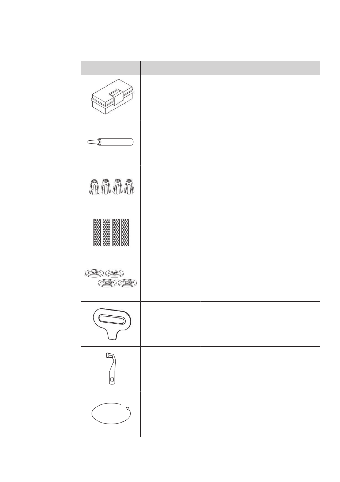
Accessories Box
Illustration Name Purpose
Accessories box To store the supplied accessories as well as
optional accessories.
Overlocker Oil For oiling the looper components.
(see page80)
Spool Stabilizers (4x) To stabilize the thread cone on the Thread Stand.
Spool Nets (4x) To support even unwinding of nylon, rayon, silk or
metallic threads from the spool.
Spool Discs (4x) To support an even unwinding of the thread from
small thread spools.
Screwdriver To loosen/tighten the Stitch Plate Screws.
Knife To exchange the knife.
Threading Wire To thread the looper threads manually in the air
threader pipe.

My bernette Overlocker
19
2023-06 EN 5040064.10A.04
Illustration Name Purpose
Decorative Thread
Guide
To sew with decorative threads for particularly
wide and long stitches, for seams and edge
finishing.
Setting Up the Machine
20
2023-06 EN 5040064.10A.04
3 Setting Up the Machine
3.1 Working Area
A stable table with a secure stand is a good prerequisite for optimal sewing results. Ergonomics around the
sewing table is an important point to protect the muscles and joints of the back, shoulder, arms and hands.
The recommendation for this includes matching the height of the table and the body posture. Avoid staying
in the same position for long periods.
> Place the machine on a stable table.
> Before operating the machine again after storage, leave the machine unpacked for approx. 1 h at room
temperature.
Correct sitting position
> Sit comfortably in front of the machine.
> Hold the arms 90 ° across the table, with your fingertips to the machine.
– The fingertips should touch the Stich Plate.
3.2 Connection and Switching On
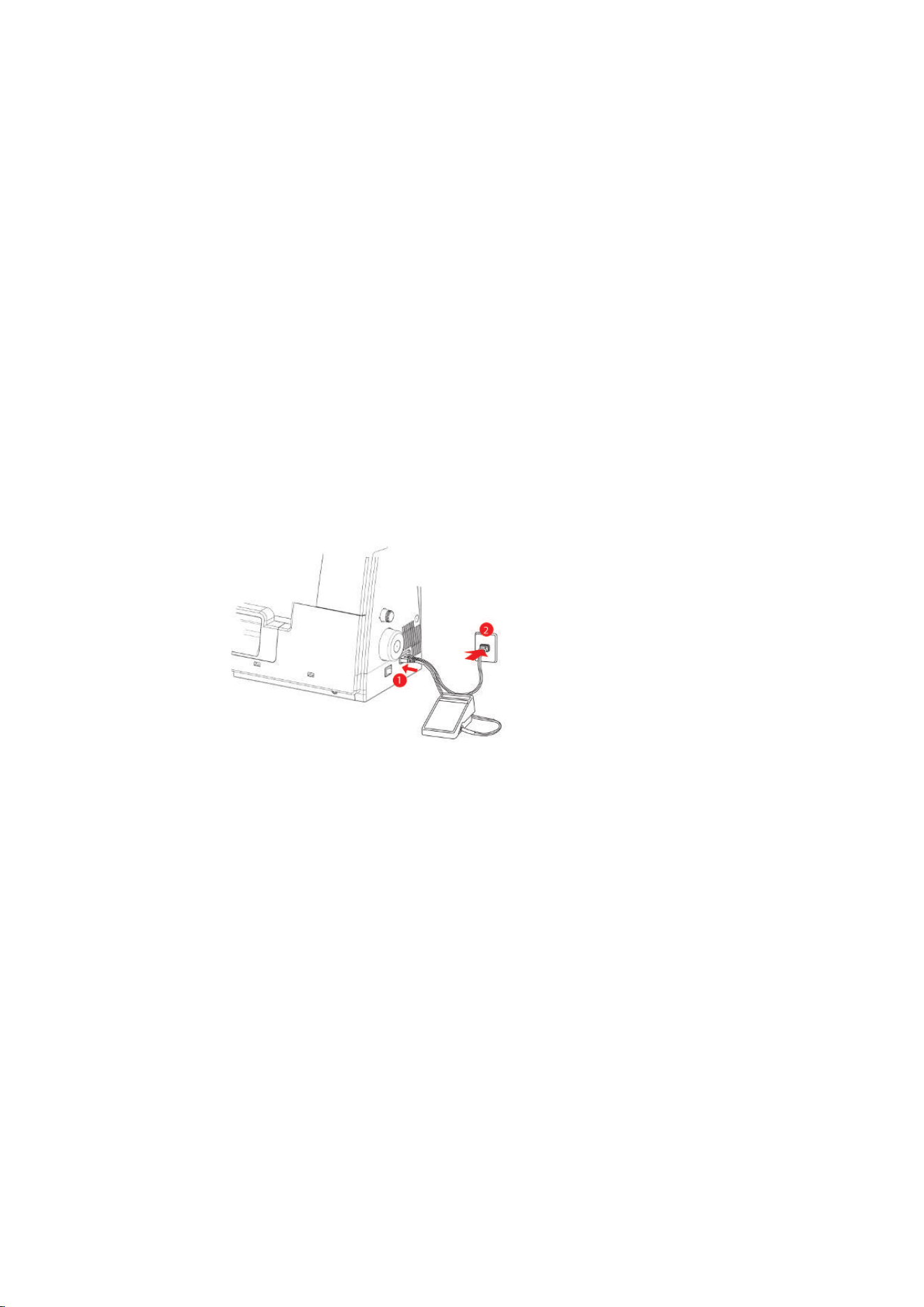
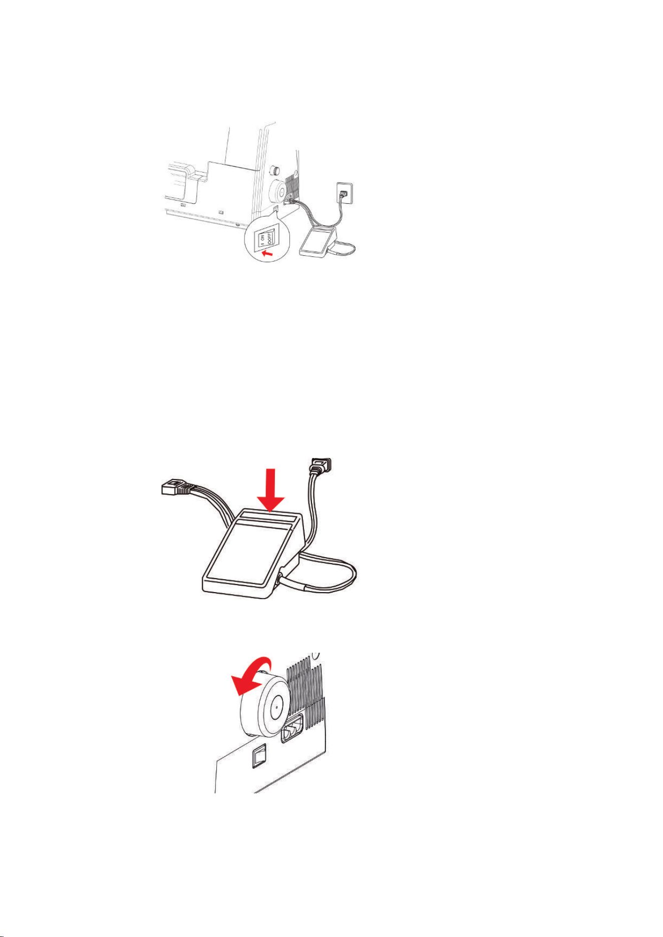
Connecting the Machine and Foot Control
> Insert the plug (1) of the Power Cable and the Foot Control cable into the connection.
> Insert the plug (2) of the Power Cable and the Foot Control cable into the socket outlet.
Use of the Power Cable (only USA/Canada)
The machine has a polarized plug (one contact is wider than the other). To reduce the risk of electric shock,
the plug can only be plugged into the socket in one way. If the plug does not fit into the socket, turn the
plug. If it still does not fit, contact an electrician to install an appropriate outlet. Do not modify the plug in
any way.
Setting Up the Machine
21
2023-06 EN 5040064.10A.04
Switching the Machine and Sewing Light On/Off
> Set the Power Switch to «I».
– The machine and the Sewing Light switch on.
> Turn the Power Switch to «0».
– The machine switches off.
– The sewing light switches off time-delayed to the machine.
3.3 Foot Control
Press the Foot Control
By operating the foot control the needle and knife move. The sewing speed can be infinitely adjusted by
more or less pressure on the foot control.
> To start the sewing process, increase the pressure on the foot control.
> To stop the sewing process, reduce the pressure on the foot control.
3.4 Handwheel
By turning the Handwheel counterclockwise, several activities can be performed.
• Slow, precise placement of the needle
• Moving the Loopers
• Moving the Knife
• Mechanical coupling of the Air Threader
Setting Up the Machine
22
2023-06 EN 5040064.10A.04
3.5 Machine Covers
The machine covers protect against injuries caused by moving components and prevent fragile elements
from being damaged. All covers must be fitted or closed prior to sewing.
• Needle Threader Cover
• Knife Cover Insert
Open/Close the Threader Cover
The Threader Cover protects the inserted looper threads during sewing operations.
> To open the threader cover, push it to the right and swing it forward.
> To close the threader cover, swing the threader cover up until it clicks into place to the left.
If the Threader Cover cannot be closed completely, the Air Threader Connector is still switched on.
3.6 Spool Holder
The Thread Stand is placed on the back of the machine. Thread cones, foot spools or household spools of all
sizes can be placed on the Thread Stand.
Attaching the Spool Holder
> To fit the Thread Stand, press the connection points from behind towards the front of the machine (1)
and snap them into place on the right (2) of the machine.
Setting Up the Machine
23
2023-06 EN 5040064.10A.04
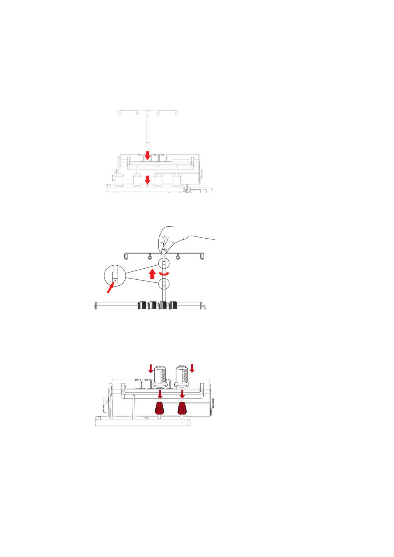
Preparing the Thread Guide
The Thread Guide ensures a clean unwinding of the thread from the thread cones. Each thread is guided
through a Thread Guide Wire located directly above the thread cone.
> To attach the Retractable Thread Guide, insert it into the opening provided in the Thread Stand until it
clicks.
> Hold the Thread Guide and pull it up to the stop.
> Turn the Thread Guide to the left and right until the two positioning pins engage.
– The outer Thread Guide Wires are parallel to the machine front.
> When not in use, retract the Thread Guide with a little pressure downwards.
Attaching the Spool Stabilizer
For large thread cones, the spool stabilizer serves to stabilize the thread cone on the spool pin.
> For extremely conical spools, place the spool stabilizer onto the thread spool pin with the pointy end up.
> For slightly conical spools, place the spool stabilizer onto the thread spool pin with the pointy end down.
Setting Up the Machine
24
2023-06 EN 5040064.10A.04
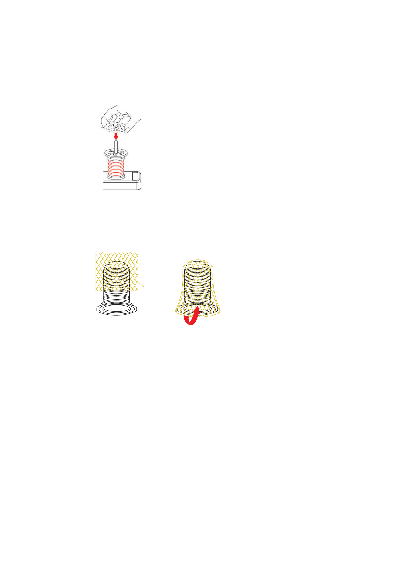
Place the Spool Disc
The Spool Disc ensures the stability of the thread spool and the even unwinding of the thread.
> Place the thread spool on the Thread Stand.
> Push the flat side of the Spool Disc over the Spool Pin to the thread spool.
Using the Spool Net
The spool net prevents the thread from sliding down from the thread spool and is recommended for special
threads.
• Thin threads, which slide easily off the spool
• Nylon, rayon, silk threads or effect and metallic threads
> Put the spool net over the thread spool from above and pull the thread end upwards.
Setting Up the Machine
25
2023-06 EN 5040064.10A.04
3.7 Presser Foot
Positioning the Presser Foot Up/Down
The lifted presser foot allows you to place the sewing project under the presser foot. The lowered presser
foot is a prerequisite for starting to sew.
> Lift the presser foot lifter until it engages.
– The presser foot remains in the upper position.
– The thread tension is released.
> Lower the presser foot lifter.
– The machine is ready for sewing.
– The thread tension is active.
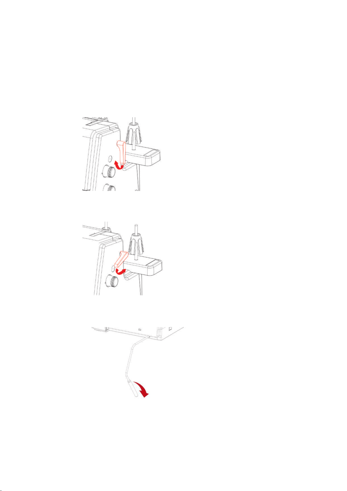
Lifting the Presser Foot Up/Down with the Knee Lifter
Temporarily lifting the presser foot using the Free Hand System allows the sewing project to be repositioned
using both hands.
Prerequisite:
• The Knee Lifter of the Free Hand System is attached. (see page30)
> To raise the presser foot, press the Knee Lifter with the knee out to the right and hold it in place.
> To lower the raised presser foot, slowly release the pressure on the Knee Lifter.
> To lower the already engaged presser foot, press the knee lifter all the way to the right and release
slowly.
Setting Up the Machine
26
2023-06 EN 5040064.10A.04
Changing the Presser Foot
Prerequisite:
• The needles are in the top position.
• The presser foot is raised.
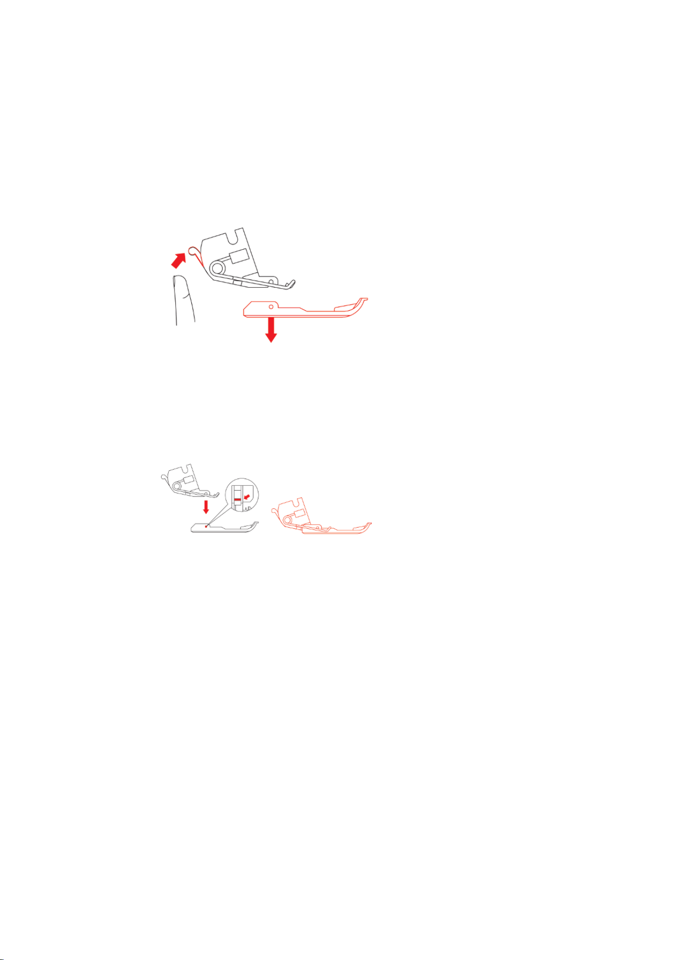
> Press the Release Button on the rear side of the Presser Foot Shaft.
– The presser foot is released.
> Lift the Presser Foot Spring slightly and remove the presser foot.
> Lift the Presser Foot Spring slightly and place the new presser foot beneath the shaft groove so that the
shaft groove lies exactly above the Presser Foot Pin.
> Lower the Presser Foot Shaft carefully until the shaft groove engages with the Presser Foot Pin.
> Raise the presser foot.
Setting Up the Machine
27
2023-06 EN 5040064.10A.04
3.8 Needle Area
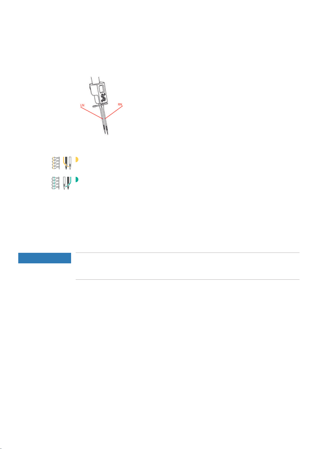
Needle Holder
Needles for Overlock Stitches
«LN» Left Needle for Overlock Stitches.
«RN» Right Needle for Overlock Stitches.
Changing the needle
The use of the Needle Inserter is recommended and prevents the needle from falling into the Feed Dog area.
(see page17)
The Needle Holder Screws must always be tightened, even if no needles are inserted, this prevents the
Needle Holding Screws from falling out because of vibration. Correctly inserted needles are not at the same
height.
NOTICE
Damage due to Excessive Tightening of the Screws
The threads of the needle holder may be damaged. A repair by the authorized bernette dealer is required.
> Do not overtighten the needle screws.
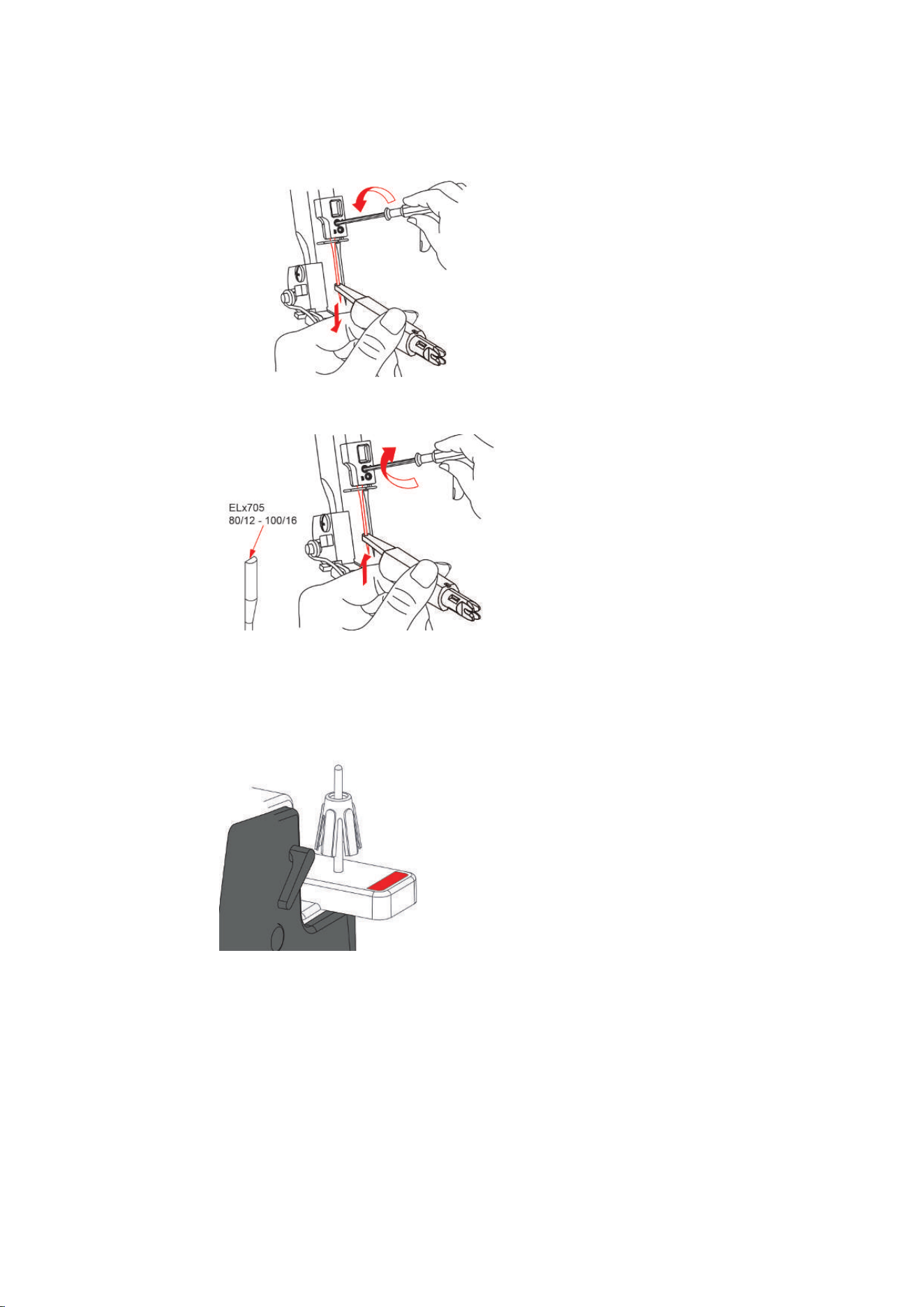
The Needle Holder can hold two needles. The machine is designed for needles of the ELx705 system. Needle
sizes between 80 − 100 are to be used for this machine. (see page35)
Prerequisite:
• The needles are in the top position.
Setting Up the Machine
28
2023-06 EN 5040064.10A.04
> Guide the Needle Inserter from below over the needle and loosen the Needle Screw using the supplied
Screwdriver.
> Pull the needle downwards to remove.
> Insert the new needle into the Needle Inserter with the flat side facing back.
> Push the needle into the corresponding Needle Holder opening as far as it will go.
> Tighten the Needle Holder Screws.
Needle Pad
The needle pad is used to store needles that are not being used.
Setting Up the Machine
29
2023-06 EN 5040064.10A.04
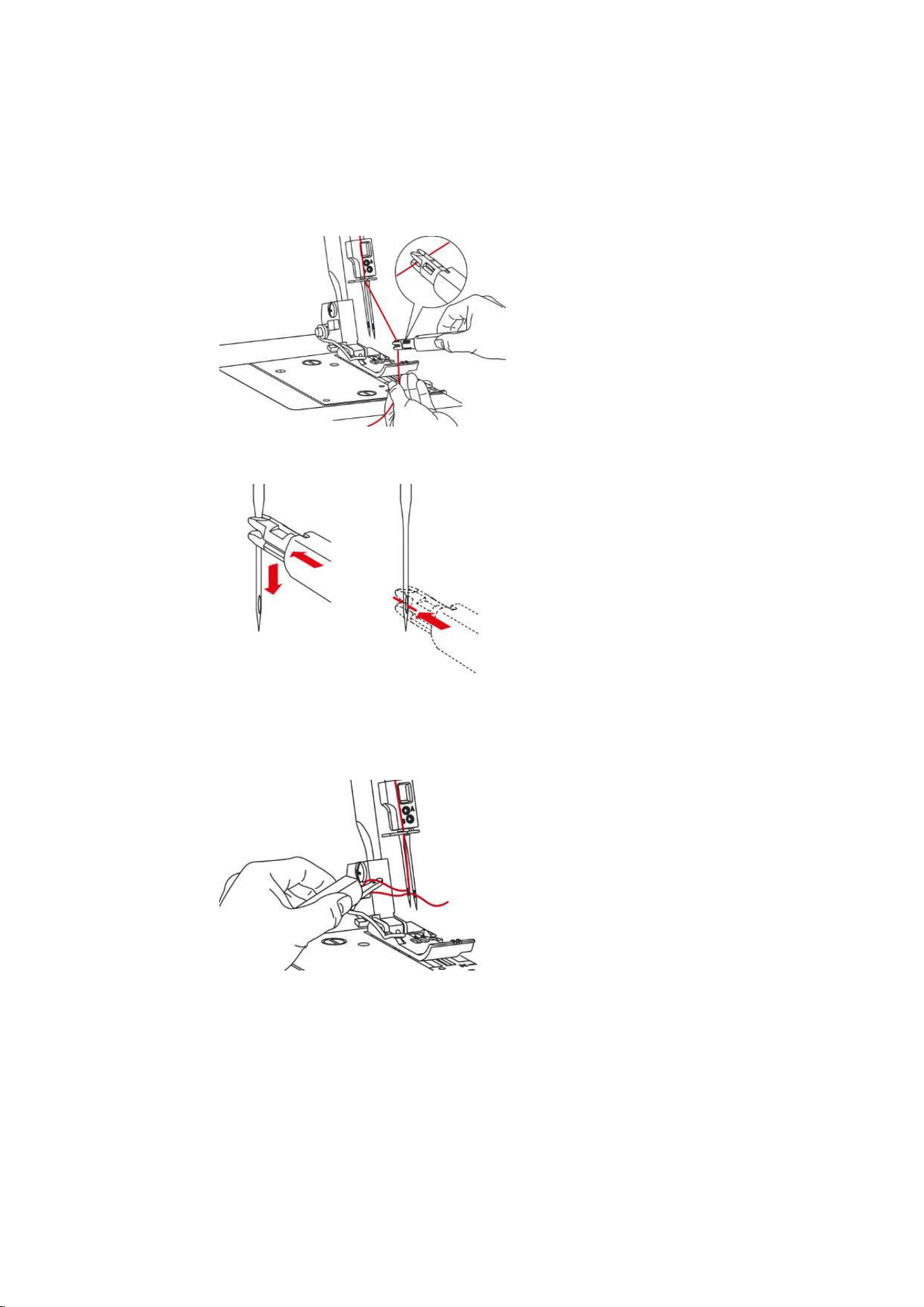
Threading the Needle Manually
With the needle threader every needle can be threaded easily.
> Hold the Needle Threader with the flat grip side facing up.
> Pull the thread horizontally through the slot and hold the end of the thread.
> Position the Needle Threader with the V-guide at the top of the needle and with little pressure slide along
the needle to the eye.
– The metal pin presses the thread through the eye of the needle.
> Release the pressure on the Needle Threader and remove it from the needle.
– A thread loop is formed.
> Pull the thread loop with the end of the Needle Threader to the back.
> Place the thread under the presser foot to the back left.
Positioning the Needles Up/Down
The needle position up/down is recommended for various actions.
• to change the needle
• to thread the needle
• to activate the air threader pipes
• to change the presser foot
> To move the needle manually, turn the handwheel counter-clockwise until the desired needle position is
reached.
Setting Up the Machine
30
2023-06 EN 5040064.10A.04
3.9 Sewing Assistance
Using the Thread Cutter
The thread cutter is used to cut the threads/thread chain.
> Pull the threads/thread chain down from the front into the thread cutter.
– The threads/thread chains are held after cutting and are ready for sewing.
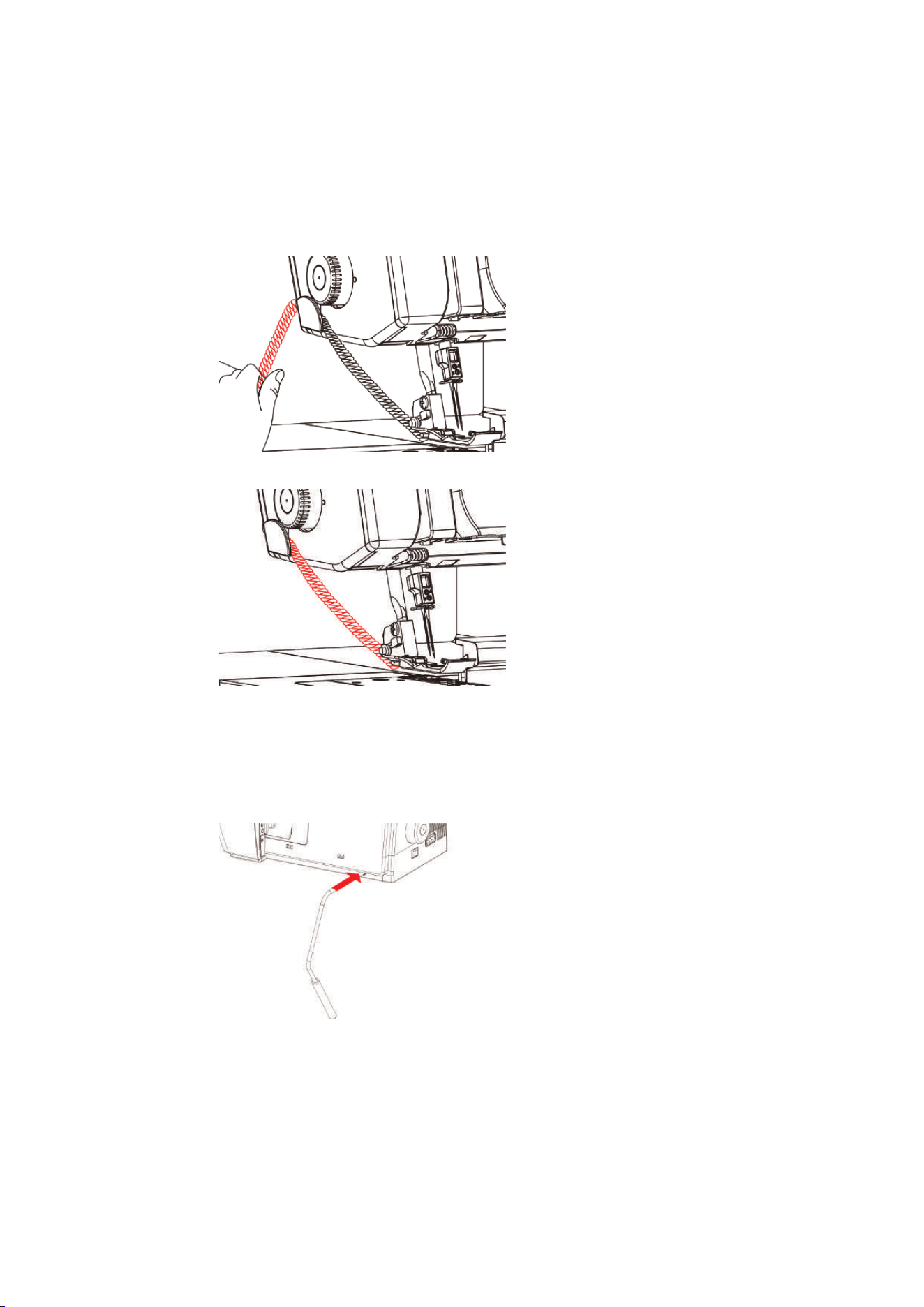
Attaching/Removing the Knee Llifter
Temporarily lifting the presser foot using the Free Hand System allows the sewing project to be repositioned
using both hands.
> To attach the Knee Lifter, push the Knee Lifter Engaging Cam in a horizontal position into the Knee Lifter
Connection until it stops.
> To remove the Knee Lifter, pull the Knee Lifter out of the Knee Lifter Connection without swinging the
Knee Lifter sideways.
Setting Up the Machine
31
2023-06 EN 5040064.10A.04
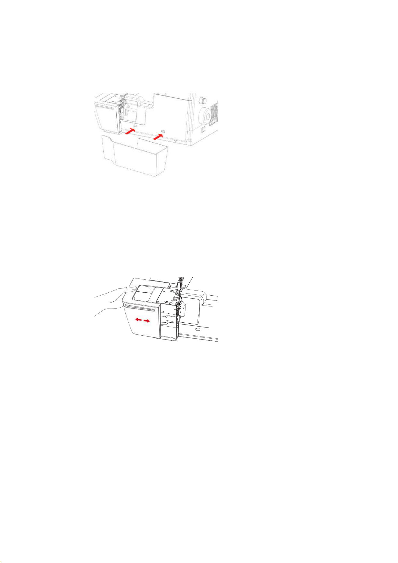
Attaching/Removing the Cut-offs Bin
The cut-offs bin catches the fabric scraps during the sewing process.
> To attach the cut-offs bin, hook the cut-offs bin into the snap-in opening on the looper cover.
> To remove the cut-offs bin, lift the cut-offs bin out of the snap-in opening on the looper cover.
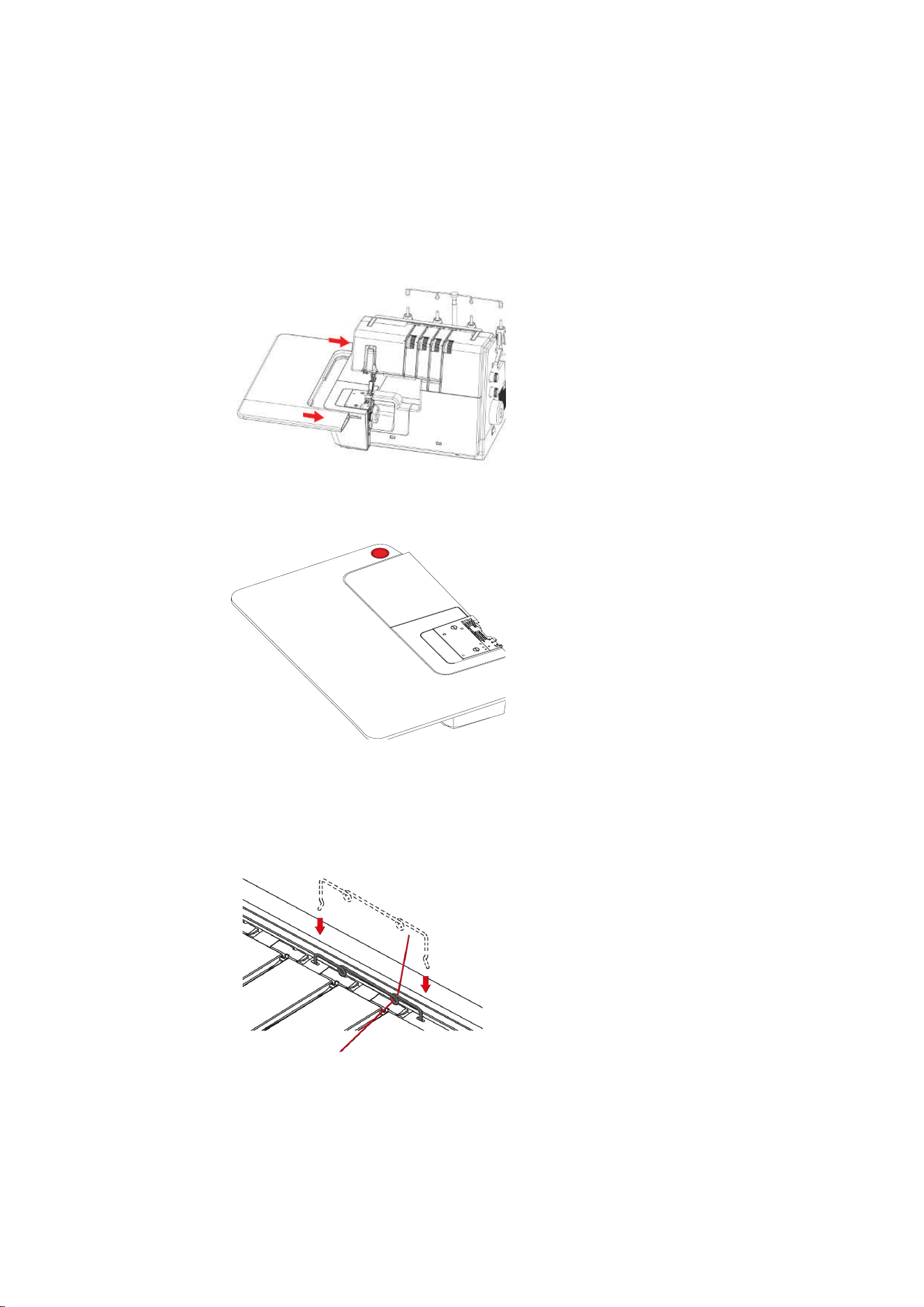
Attaching/Removing the Freearm Cover
The freearm is ideal when working with tubular, closed projects such as cuffs, trouser hems or sleeve ends.
The freearm cover closes the gap between the stitch plate and the sewing surface.
Prerequisite:
• The slide-on table is removed.
> To attach the freearm cover, push the freearm cover along the guide rails from the left until it engages.
> To remove the freearm cover, pull the freearm cover to the left.
Setting Up the Machine
32
2023-06 EN 5040064.10A.04
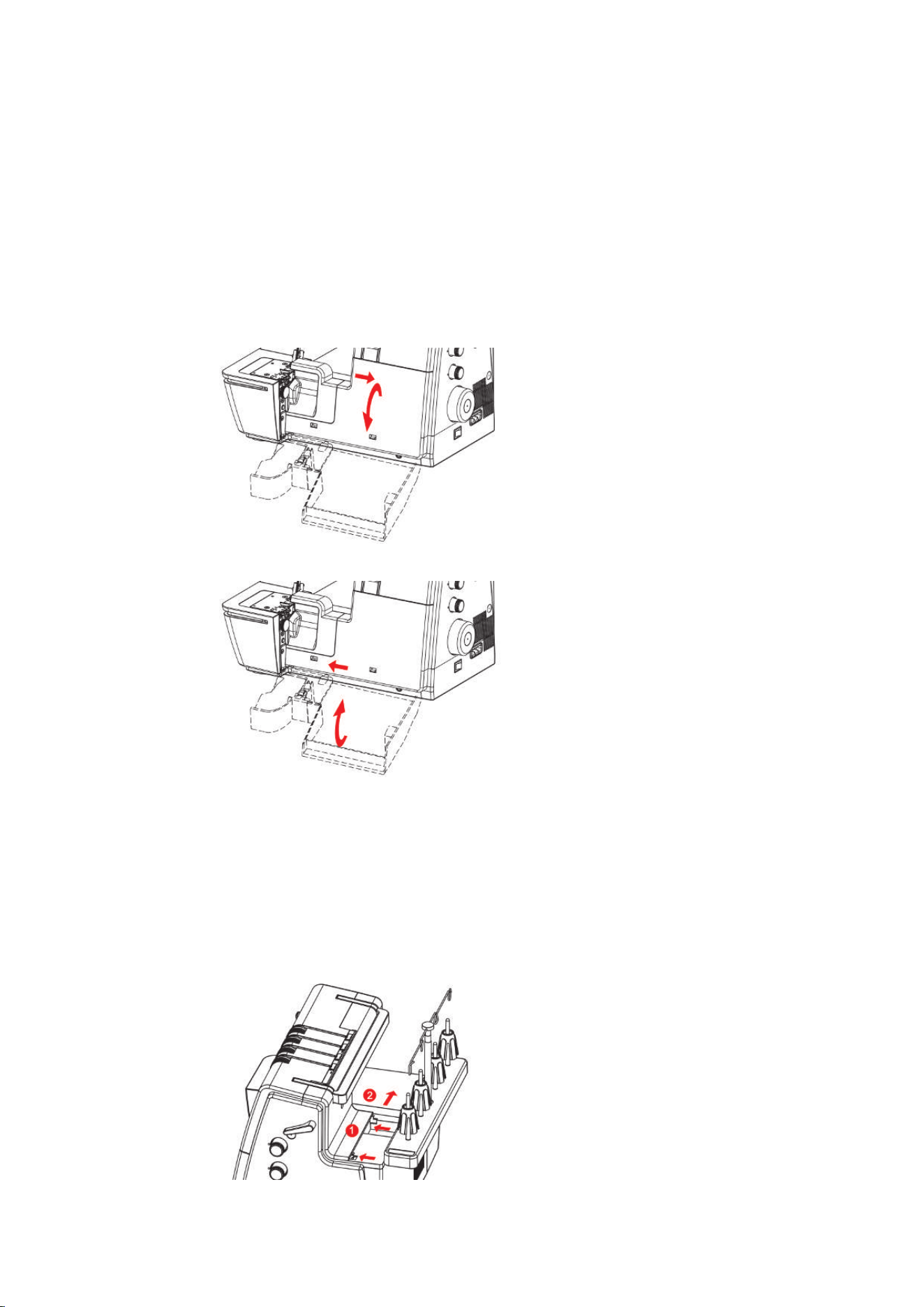
Attaching/removing the Slide-on Table
The Slide-on Table increases the sewing surface, especially helpful with larger sewing projects.
Prerequisite:
• Freearm Cover is attached.
> To attach the Slide-on Table, push the Slide-on Table along the Guide Rails from the left until it engages.
> To remove the Slide-on Table, press the Release Mechanism (1) of the Slide-on Table and pull the Slide-
on Table to the left.
1
Attaching the Decorative Threads Guide
> Tension the Decorative Threads Guide slightly and hook it into the left and right recesses in the machine
cover.
> Thread the thread through the Thread Guide Eyelet and insert it along the thread path between the
Thread Tension Discs.
Fitting with thread already inserted
> Pull the thread out of the Thread Pretension.
> Attach one end of the Decorative Threads Guide.
> Thread the thread into the Decorative Threads Guide.
> Attach the second end of the Decorative Threads Guide.

Sewing Start
33
2023-06 EN 5040064.10A.04
4 Sewing Start
4.1 Check before starting to sew
In order to start a project successfully, the following steps must be performed.
• The machine is switched on and the presser foot is lifted.
• The fabric and the application have been selected. (see page33)
• The thread has been selected. (see page33)
• The needle size matches with the thread type and the sewing project. (see page35)
• The stitch has been selected. (see page41)
• The machine settings based on the stitch selection have been performed. (see page41) / (see page43)
• Threading has been performed according to the Stitch Chart.
• All Needle Threads and Looper Threads lie under the presser foot to the back left.
• Threader Cover is closed.
> Lower the presser foot.
> To start the sewing process, press the foot control.
– A thread chain is formed.
– If no thread chain is formed, the settings on the machine for the stitch must be checked.
4.2 Selecting the Fabric
The choice of fabric, in combination with needle, thread and stitch, plays a vital role in achieving the perfect
sewing result. The sewing test with the selected fabric is recommended. (see page62)
4.3 Selecting the Thread
A wide range of sewing and special overlock threads are manufactured in various sizes and in different fiber
combinations.
• The purchase of quality threads is recommended to achieve good sewing results.
• Use thread cones/spools which are suitable for overlocker machines.
NOTICE
Thread breakage due to incorrect Needle/Thread or Thread/Looper matching
The thread needs to glide smoothly through the respective Thread Guides.
It must be possible to feed the thread through the Looper or the Needle Eye without any resistance.
In the case of thick threads, elongate the stitch length and reduce the Thread Tension.

Sewing Start
34
2023-06 EN 5040064.10A.04
Needle Thread
Needle size and thread type must be carefully matched. The correct needle thickness depends on the
selected thread as well as the fabric being used.
• The fabric type determines the thread type and point form.
• The thread type determines the needle size.
Needle sizes of 80/12 100/16 can be used on the machine.
Thread type Needle size
Polyester Overlock Thread No. 120 #80 – #100
Polyester Multifilament < No. 120 80 – 90
Wooly Nylon #80 – #100
Decorative Thread/Yarn #80 – #100
Metallic Thread #80 – #100
Check the Needle/Thread Combination
The needle/thread combination is correct if the thread is guided perfectly into the long
groove and through the eye of the needle.
The thread can break and cause skipped stitches if there is too much play in the long
groove or eye of the needle.
The thread can break and become jammed if it frays on the edges of the long groove and
is not guided optimally through the eye of the needle.
Looper Thread
A wide variety of thread types can be used as Looper Threads which can be threaded using the Air Threader
System.
NOTICE
Damage by coated or waxed threads
Coated or waxed threads may lose some of their coating in the Air Threader Pipes, which results in
permanent blocking of the pipes. A repair by the Authorized bernette dealer is required.
Avoid the use of coated or waxed threads.
Sewing Start
35
2023-06 EN 5040064.10A.04
4.4 Selecting the Needle
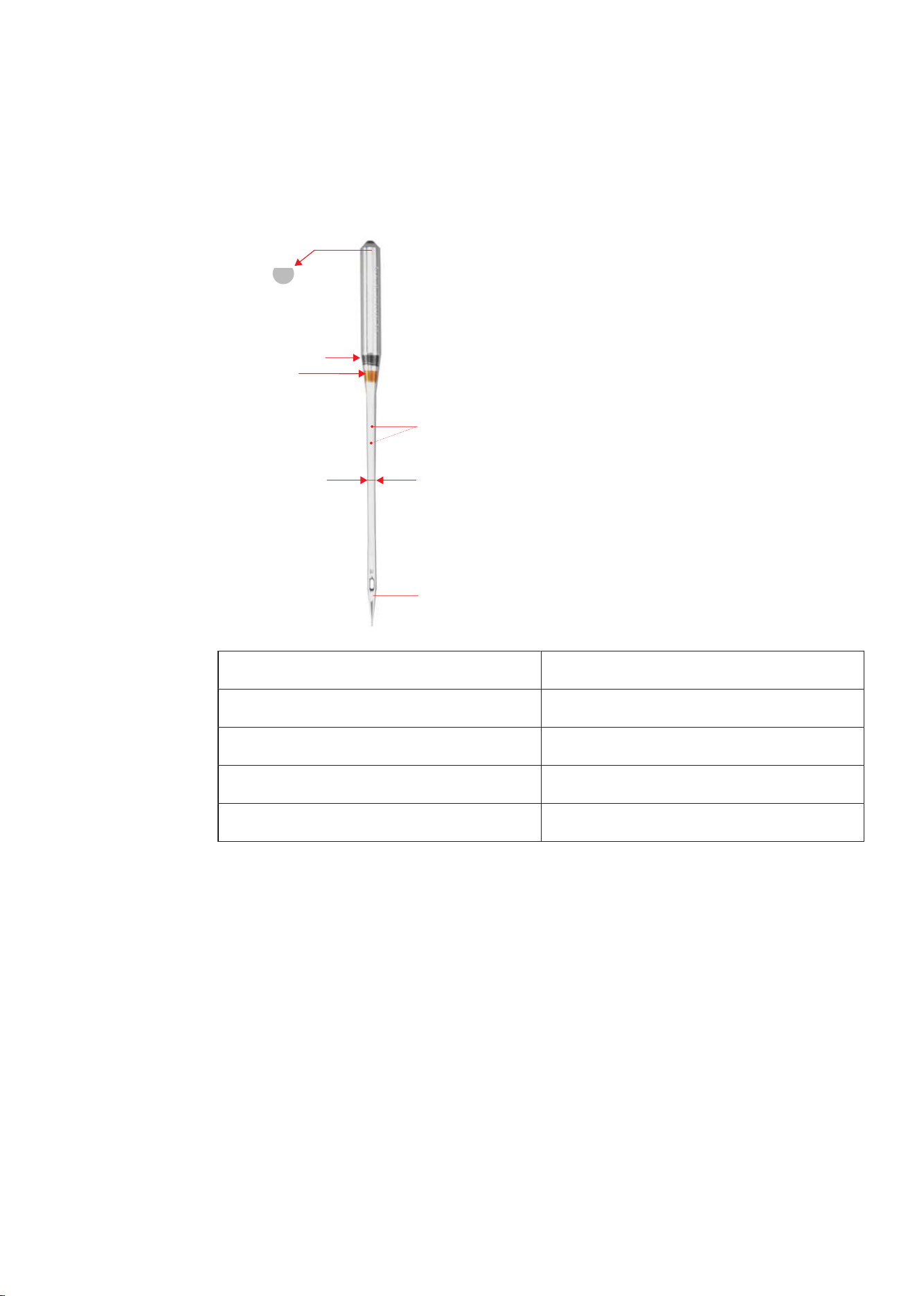
It is recommended to use the Needle Type ELx705 CF (Chrome Finish) version, as they are more durable.The
machine runs most reliably with these needles because of their second groove.
2
1
3
4
A
B
A Coverstitch Needle ELx705 CF/80
1 two thread grooves
2 705 = Flat shank
3 CF = Chrome Finish
4 / B 80 = Needle size
The needles should be replaced regularly. Only a perfect needle point can achieve a proper stitch.
• Needle size 80: For any common applications. for mid-weight to heavy fabrics.
• Needle size 90: for heavy fabrics.
• Needle sizes >90: In exceptional cases, only for very heavy fabrics.
Sewing Start
36
2023-06 EN 5040064.10A.04
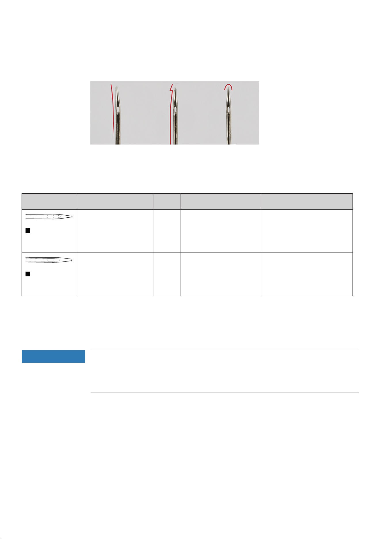
Detect Defective Needles
Check the needle before each sewing start and replace it if necessary.
1 Bent Needle 3 Blunt Needle
2 Damaged Needle Point
Needle Overview
Illustration Designation *Size Description Material/Application
Coverstitch Needle
ELx705 CF
80/12
90/14
100/16
With slightly rounded point, a
second groove and chrome
coating
For overlock and coverstitch
work.
Jersey/Coverstitch Needle
ELx705 SUK CF
80/12
90/14
100/16
With slightly rounded point, a
second groove and chrome
coating
For overlocking and
coverstitching on multilayer,
elastic fabrics.
*Not all needle sizes are available as BERNINA Needles.
4.5 Fixing Fabric Layers
If several layers of fabric are sewn together, they can be fixed with basting stitches sewn on the sewing
machine or by pins.
NOTICE
Damage to the Knife
Pins placed too close to the fabric edge can be caught by the knife. The needle tips can be sheared off or
the blade of the knife can be damaged.
Position the pins at an adequate distance from the edge of the fabric.
> Place the pins approx. 2cm from the edge of the fabric or remove them continuously while sewing.
Stitch
37
2023-06 EN 5040064.10A.04
5 Stitch
5.1 Stitch Type
With this machine different stitch formations can be set. These stitches are achieved by different
configurations of needles and mechanical settings.
Overlock Stitch
The 3- and 4-thread overlock are considered standard Overlock Stitches for sewing two layers of fabric
together, for finishing cut edges, e. g. facings, hem edges and seam allowances that are ironed apart.
The 2-thread overlock is ideal for finishing a fabric edge.
4-Thread Overlock
The 4-Thread Overlock is the most durable stitch thanks to the safety seam. The left and right overlock
needle thread as well as the upper and lower looper thread are required for this stitch. The overlock needle
threads form two parallel stitch rows, which on the front side look like step stitch rows of a sewing machine.
On the wrong side, the overlock needle threads form «dots» to catch the under looper thread when the
fabric is pierced, whereby the right overlock needle thread also serves as a safety seam.
3-Thread Overlock
The 3-Thread Overlock is usually stretchable than the 4-Thread. Therefore it is ideal for seams on knitted
fabrics (LN wide) or fine fabrics (RN narrow).
2-Thread Overlock
The 2-Thread Overlock is formed with an overlock needle thread (LN wide or RN narrow) and the under
looper thread. The lower looper thread is guided to the right side of the fabric by means of the hooked-in
upper looper converter. This overlock stitch is only suitable for edge finishing.
Stitch
38
2023-06 EN 5040064.10A.04
Select stitch by application
Finishing Edges
The finishing of a fabric edge is mostly used as preparation for open seams or as a decorative edge finish.
Stitch Number Stitch Name Stitch Pattern
No.3 3-Thread Overlock Wide (LN)
No.4 3-Thread Overlock Narrow (RN)
No.8 3-Thread Rolled Hem
No.9 2-Thread Wrapped Overlock
Wide (LN)
No.10 2-Thread Wrapped Overlock
Narrow (RN)
No.13 2-Thread Rolled Hem
No.14 2-Thread Overlock Wide (LN)
No.15 2-Thread Overlock Narrow (RN)
No.30 3-thread picot stitch
Stitch
39
2023-06 EN 5040064.10A.04
Seam
Seams are at least two layers of fabric, which are usually placed right side on right side and then sewn
together. There are two different types of seams.
• Closed seams
• Flat seams
Closed Seam
For closed seams 3-thread or 4-thread overlock stitches are suitable, because they loop around both fabric
edges and sew them together. These stitches are mainly chosen for garments made of knitted fabrics and for
wide cut garments made of woven fabrics.
Stitch Number Stitch Name Stitch Pattern
No.1 4-Thread Overlock with
Integrated Safety Seam
No.2 3-Thread Super Stretch
No.3 3-Thread Overlock Wide (LN)
No.4 3-Thread Overlock Narrow (RN)
No.7 3-Thread Rolled Seam
Stitch
40
2023-06 EN 5040064.10A.04
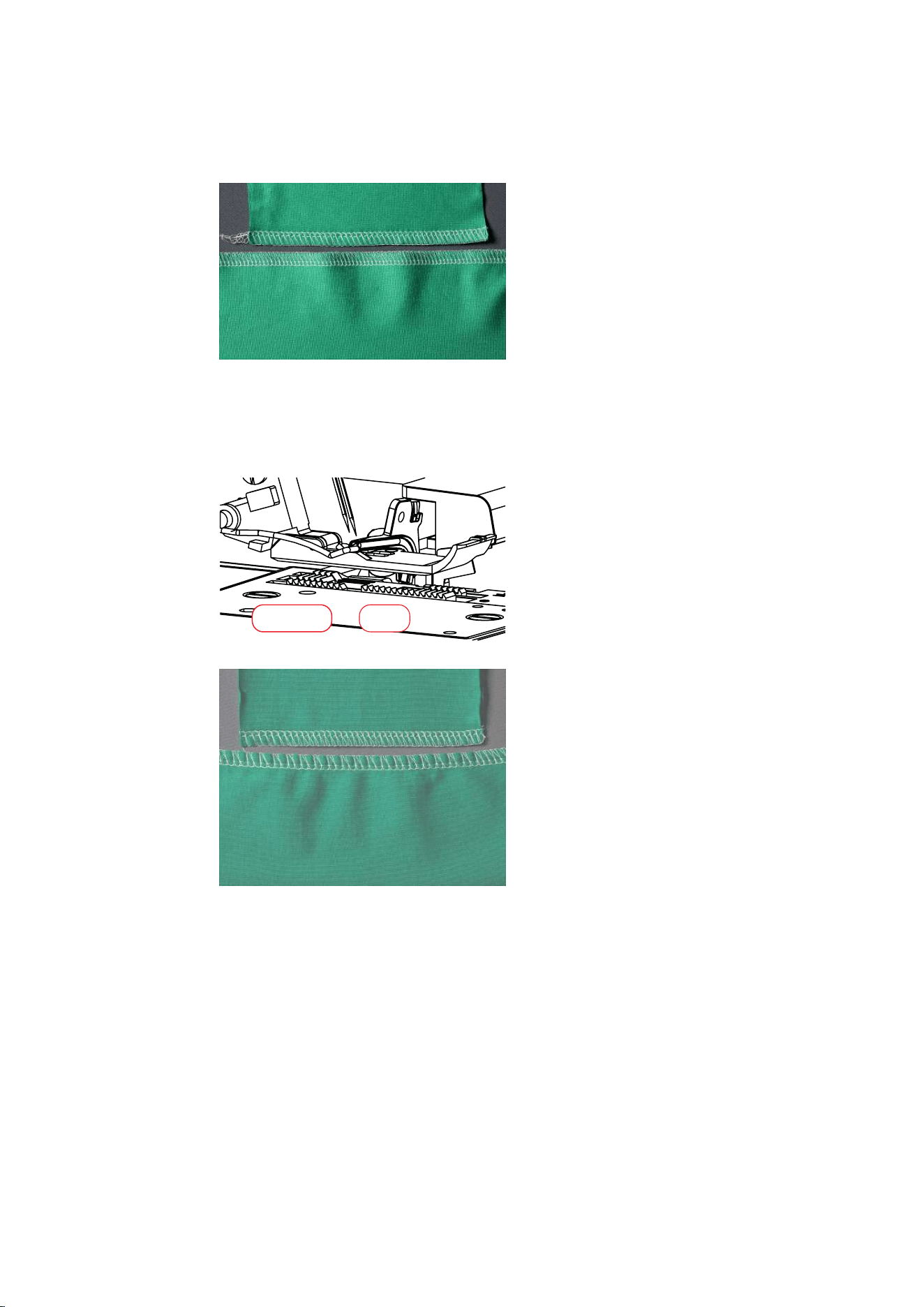
Flatlock for Flat Seams
The flatlock forms loops on the upper side of the seam and stitches on the underside.
> Thread and set the machine for 2- or 3-Thread Flatlock.
> Sew two layers of fabric together (wrong side on wrong side).
> Carefully separate the two layers of fabric.
– The two fabric edges now lie flat on top of each other at the stitch width of the flatlock.
Stitch Number Stitch Name Stitch Pattern
No.5 3-Thread Flatlock Wide (LN)
No.6 3-Thread Flatlock Narrow (RN)
No.11 2-Thread Flatlock Wide (LN)
No.12 2-Thread Flatlock Narrow (RN)
Stitch
41
2023-06 EN 5040064.10A.04
5.2 Stitch Chart
This manual includes a stitch overview with all necessary default settings for each stitch. These default values
may vary depending on the used material.
> Remove all the needles which are not required.
> Set the mtc micro thread control to «-».
No. Stitch name Stitch pattern
No.1 4-Thread Overlock with Integrated
Safety Seam
4 4 4 4 6 N 2.5 1
No.2 3-Thread Super Stretch 5 4 4 6 N 2.5 1
No.3 3-Thread Overlock Wide (LN) 4 ─ 4 4 6 N 2.5 1
No.4 3-Thread Overlock Narrow (RN) ─ 4.5 4 4 6 N 2.5 1
No.5 3-Thread Flatlock Wide (LN) 0 ─ 5 8 5.5 N 2.5 1
No.6 3-Thread Flatlock Narrow (RN) ─ 0 6.5 8 6 N 2.5 1
No.7 3-Thread Rolled Seam ─ 4.5 5 4 6 R 1.5 1
No.8 3-Thread Rolled Hem ─ 4.5 5 7 5 R 1.5 1
No.9 2-Thread Wrapped Overlock Wide (LN) 3 ─ 3.5 6 N 2.5 1
No.10 2-Thread Wrapped Overlock Narrow
(RN)
─ 5 4 6 N 2.5 1
No.11 2-Thread Flatlock Wide (LN) 0.5 ─ 7 5.5 N 2.5 1
Stitch
42
2023-06 EN 5040064.10A.04
No. Stitch name Stitch pattern
No.12 2-Thread Flatlock Narrow (RN) ─ 3 7.5 6 N 2.5 1
No.13 2-Thread Rolled Hem ─ 5 4.5 5.5 R 1.5 1
No.14 2-Thread Overlock Wide (LN) 0.5 ─ 7 5.5 N 2.5 1
No.15 2-Thread Overlock Narrow (RN) ─ 3 7.5 6 N 2.5 1
No.30 3-thread picot stitch ─ 4.5 4 5.5 5.5 R 3 1
Machine Settings
43
2023-06 EN 5040064.10A.04
6 Machine Settings
6.1 Setting the Knife
Knife On/Off
For a better overview and better access in the sewing area, e.g. for threading, the knife can be lowered (off)
and then engaged again (on). The knife is also lowered if the sewing project already has a clean cut edge
and the edge is only to be finished. The best sewing results are achieved by cutting and finishing in one
single step.
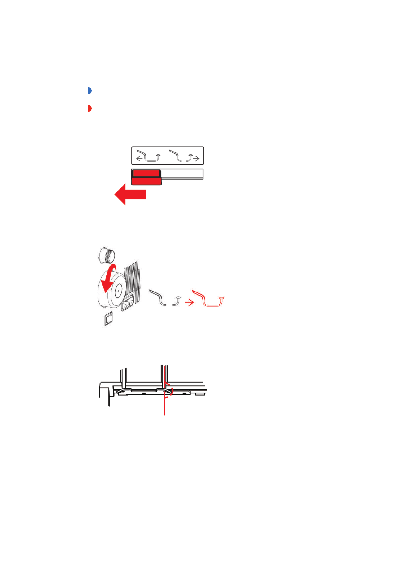
Knife Off (lowered)
> Open the Threader Cover.
> Pull the knife away from the Stitch Plate as far as possible and then lower it forwards to the lock-in
position.
– The knife is lowered.
Knife On (engaged)
> Open the Threader Cover.
> Pull the knife away from the Stitch Plate as far as possible and then lift it backwards to the lock-in
position.
– The knife is engaged.
> Close the Threader Cover.
Machine Settings
44
2023-06 EN 5040064.10A.04
NOTICE
Finger injury
Before each sewing start make sure that the Knife Cover Insert is attached.
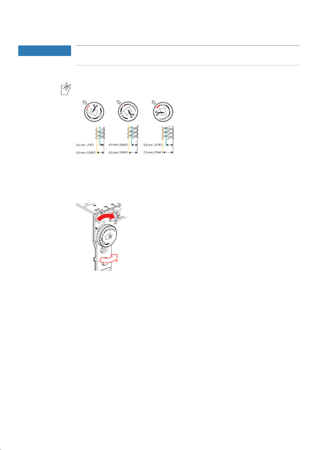
Setting the Cutting Width
The Cutting Width for the knife position can be adjusted between 3 – 7 mm.
The numbers on the scale correspond with the actual Cutting Width in mm from the Left Overlock Needle
«LN» to the cutting edge. The Cutting Width is used to determine the stitch width. The set Cutting Width is
indicated at the Cutting Width Dial. (see page48)
If the Cutting Width changes, the knife, the Stitch Fingerand the Threader Cover move in the corresponding
direction.
> To increase the Cutting Width, turn the Cutting Width Dial to the a higher value.
> To reduce the Cutting Width, turn the Cutting Width Dial to a lower value.
Machine Settings
45
2023-06 EN 5040064.10A.04
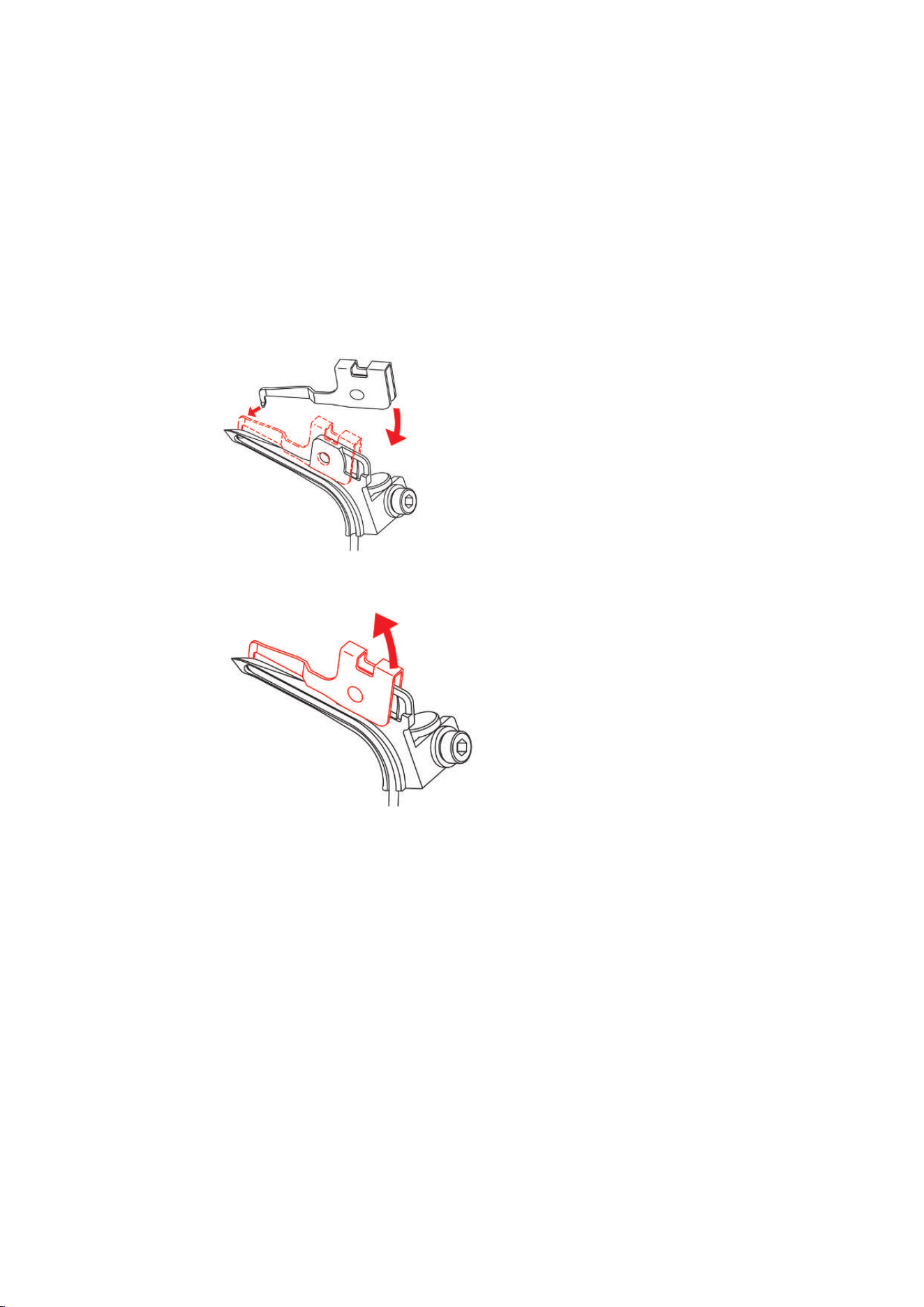
6.2 Upper Looper Converter Hooked in/Hooked out
By attaching the upper looper converter, the upper looper grabs the lower looper thread so that it covers the
entire fabric edge.
Prerequisite:
• The needles are in the top position.
• The upper looper thread is removed.
• The lower looper thread is below the upper looper.
> To hook in the upper looper cover, place the end of the upper looper cover over the elevation of the
upper looper and hook the tip of the upper looper cover into the looper eye.
> To unhook the upper looper cover, lift the end of the upper looper cover upwards and unhook the lock-
in lug from the looper eye.
Machine Settings
46
2023-06 EN 5040064.10A.04
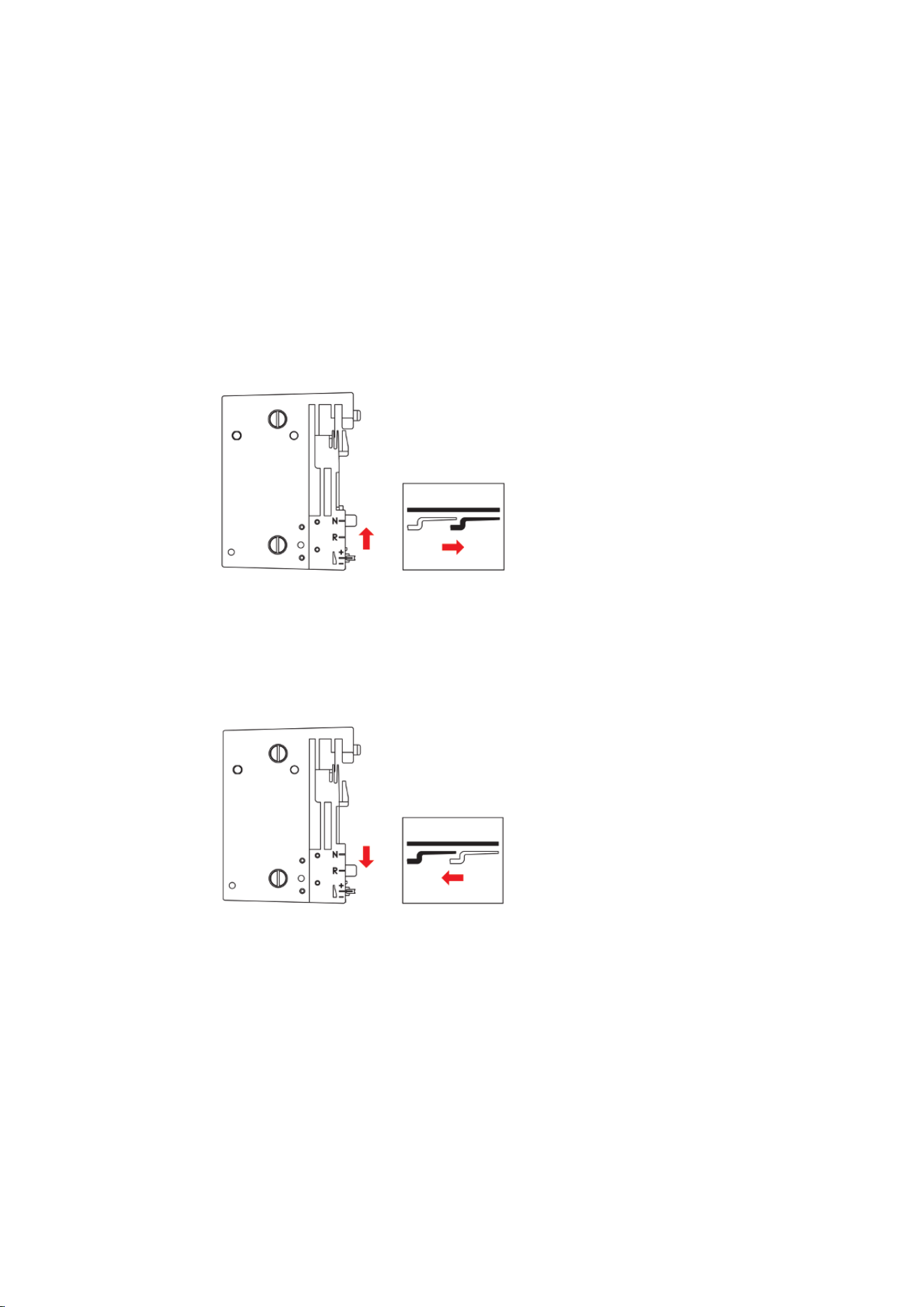
6.3 Rolled Hem Selection Lever «N/R»
Depending on the application, the Rolled Hem Selection Lever must be set to the appropriate position. The
adjustment positions for overlocking «N» and rolled hems «R» are marked in the Stitch Plate and can be set
there for the desired application.
Overlocking «N»
During overlocking, the upper and lower looper threads are laid around the stitch finger and this creates an
even distance to the cut edge. If the thread quantity at the fabric edge is too much or too little, this thread
quantity can be corrected by the mtc micro thread control. (see page47)
> Move the rolled hem selection lever to position «N».
– Overlocking is activated.
Rolled hem «R»
By retracting the stitch finger, the loops of the upper and lower loopers thread are reduced and the fabric
edge is rolled under. Rolled hems are the ideal edge finishing for fine fabrics. These are particularly suitable
for decorative finishings on scarves, evening gowns, lingerie, home textiles and as lining seams.
> Move the rolled hem selection lever to position «R».
– The rolled hem is activated.
– The stitch finger is retracted.
Machine Settings
47
2023-06 EN 5040064.10A.04
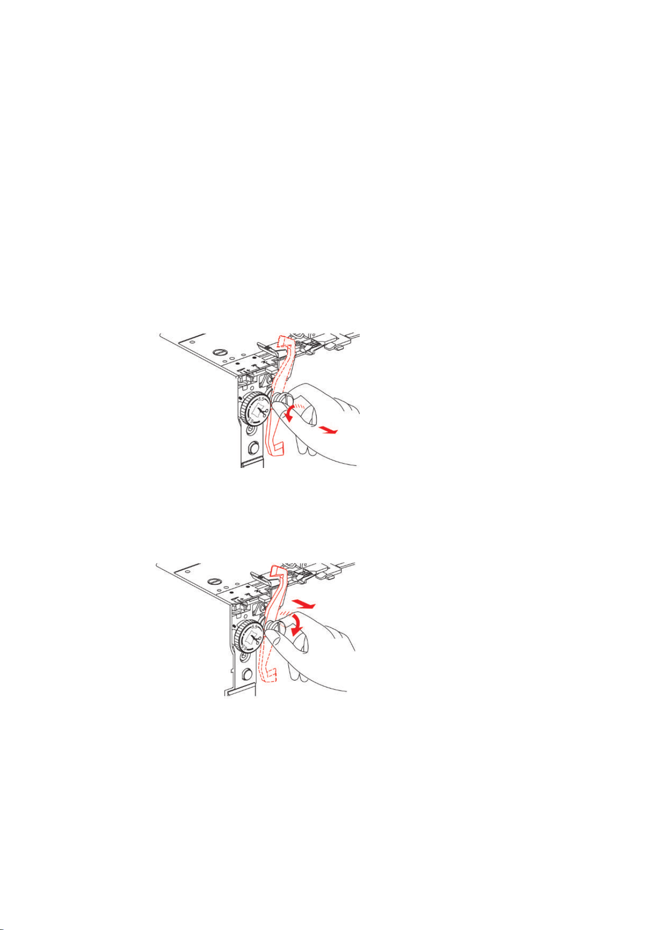
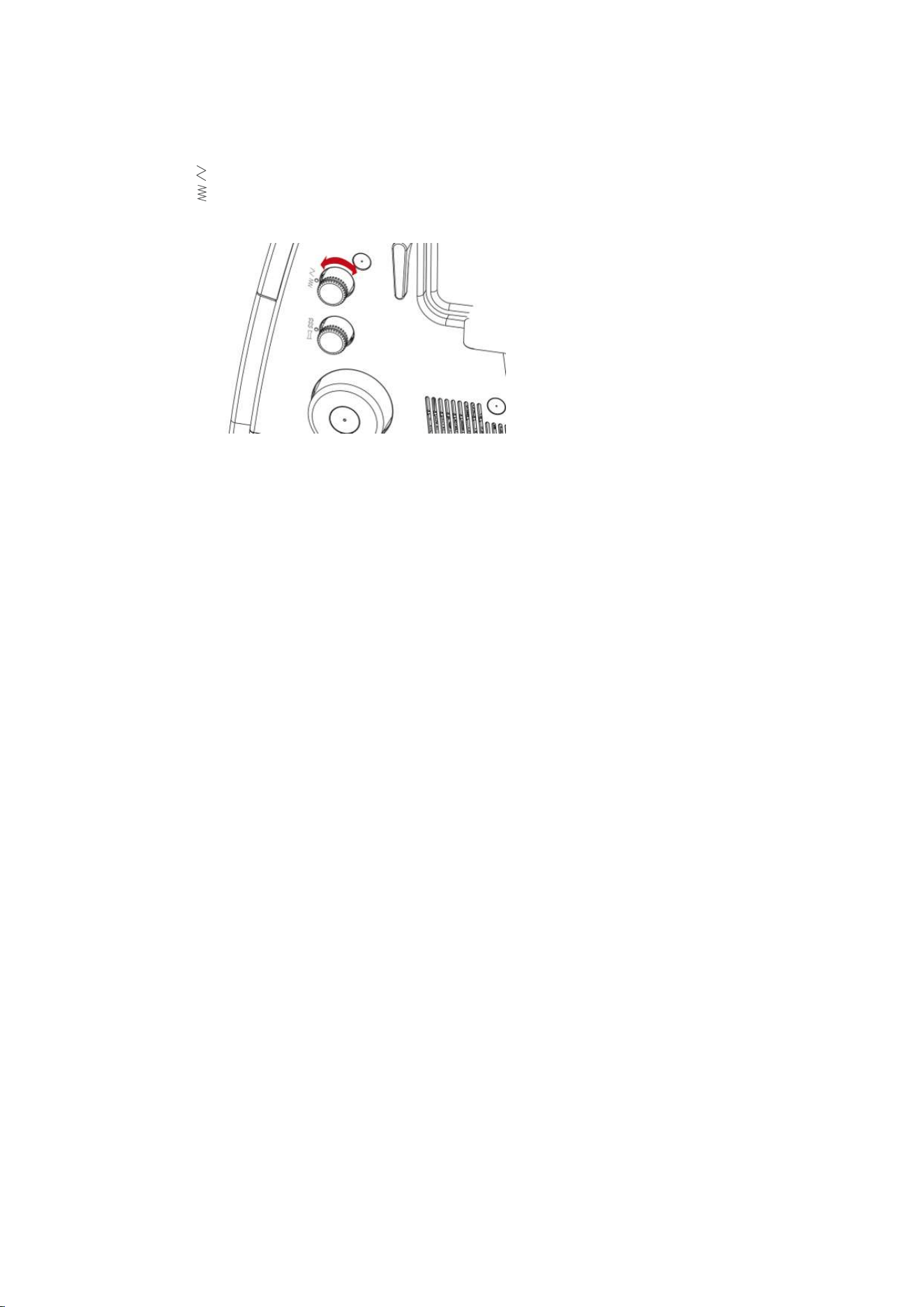
6.4 Setting the mtc micro thread control
The mtc micro thread control affects the amount of the looper thread around the fabric edge and can be
adjusted continuously while sewing. This feature makes it easy to achieve a well-balanced stitch at any given
cutting width.
Prerequisite:
• The thread tension is set correctly.
• The knife position is set correctly.
• The mtc micro thread control is set to «−».
• The sewing test has been performed.
> To enlarge the loops of the looper thread at the fabric edge, turn the mtc micro thread control in «+»
direction while sewing.
> To minimize the loops of the looper thread at the fabric edge, turn the mtc micro thread control in «-»
direction while sewing.
Machine Settings
48
2023-06 EN 5040064.10A.04
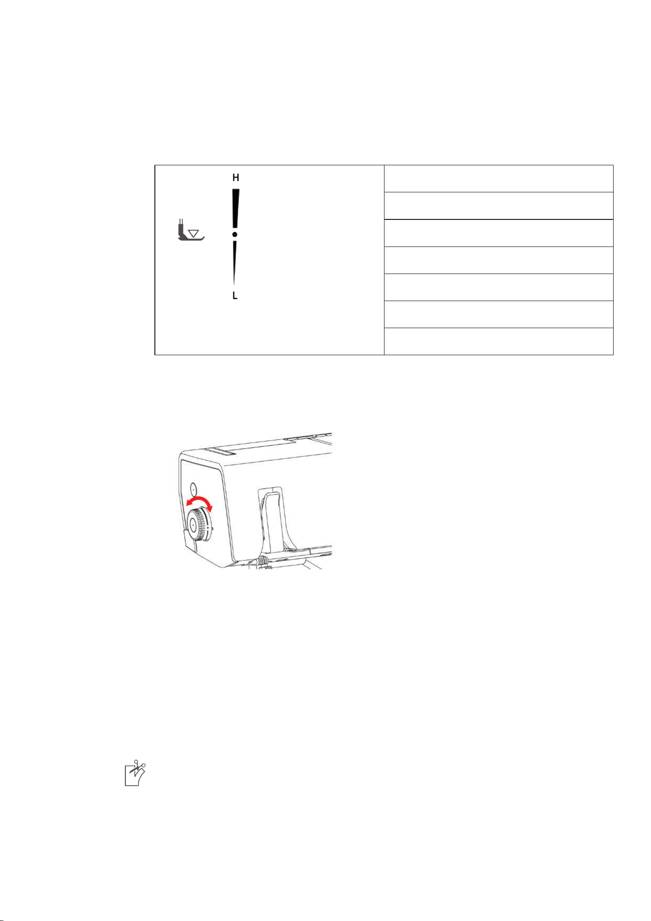
6.5 Setting the Presser Foot Pressure
The Pressure Foot Pressure has been set by the factory so that it is optimal to sew medium-weight
fabrics.Most materials do not require any adjustment of the Presser Foot Pressure. However, there are some
cases where adjustment is necessary, such as when sewing very light or heavy fabrics.
Extra high
High
Medium high
Default value
Medium light
Light
Extra light
> Reduce the Presser Foot Pressure for light fabrics.
> Increase the Presser Foot Pressure for heavy fabrics.
> Perform a sewing test to set the optimal Presser Foot Pressure for your sewing project.
> To increase the Presser Foot Pressure, set the Presser Foot Pressure Wheel to a higher value.
> To reduce the Presser Foot Pressure, set the Presser Foot Pressure Wheel to a lower value.
6.6 Adjusting the Stitch Width
The stitch width can be set in two different ways.
• Needle position
• Cutting Width
Changing the stitch width via the needle position
The stitch width can vary by the choice of needle position by 2 mm.
> To sew a wide stitch, insert the left needle.
> To sew a narrow stitch, insert right needle.
Changing the stitch width via the Cutting Width
The stitch width can vary by adjusting the knife position. The scale of the Cutting Width Dial determines the
distance between the Left Overlock Needle (LN) and the knife inmm. To the Right Overlock Needle the set
scale value is reduced by 2 mm. This means, at a Cutting Width of 6 mm and with the Right Overlock Needle
inserted, a 4 mm wide stitch is sewn.
> To adjust the stitch width, set the Cutting Width Dial between 5 ─ 7 mm. (see page44)
Machine Settings
49
2023-06 EN 5040064.10A.04
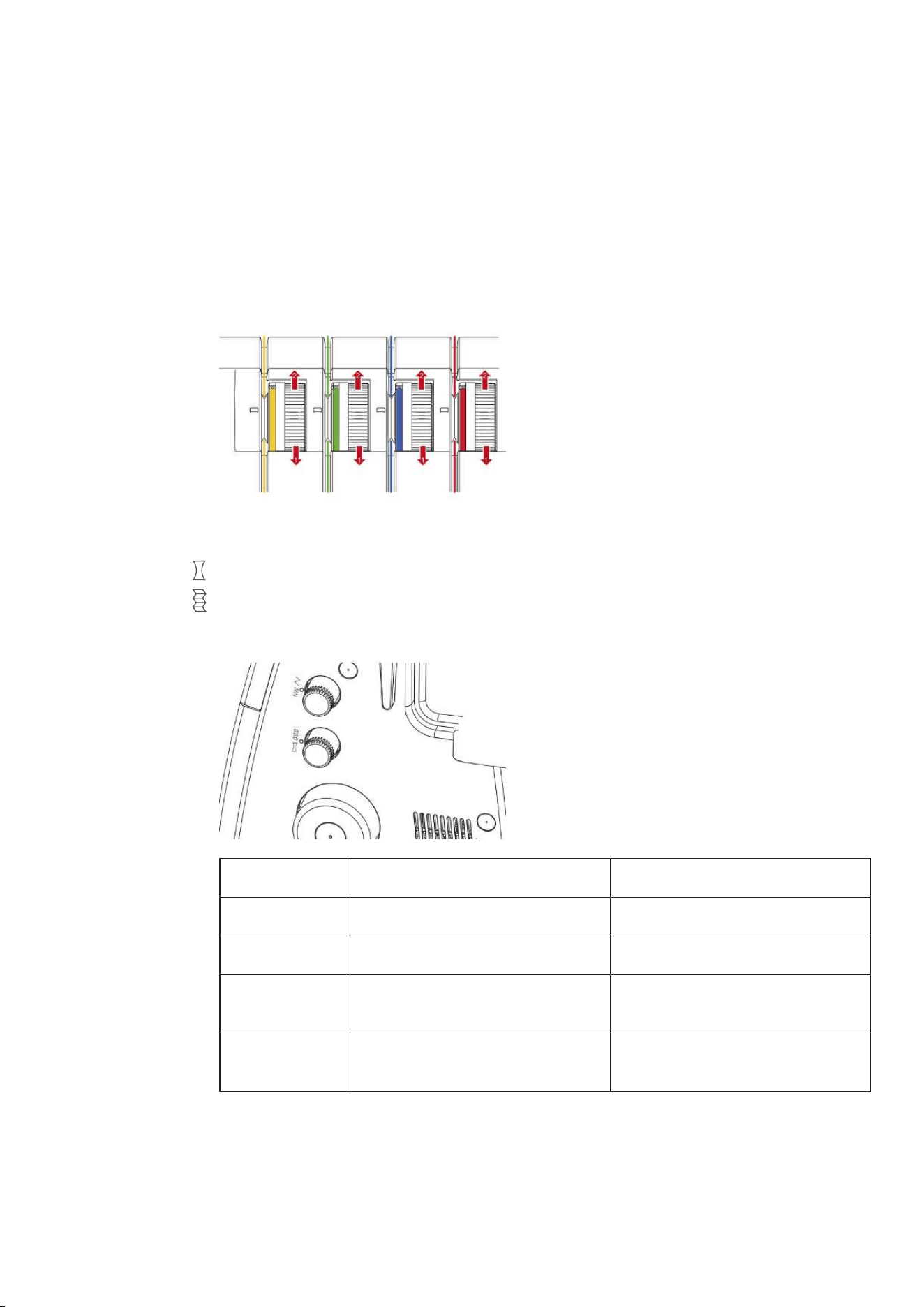
6.7 Adjusting the thread tension
The Thread Tension has a considerable influence on each individual thread and its task to perform the stitch
formation. The Stitch Chart provides a recommended default value for each stitch. This recommendation can
be optimized for different thread/fabric combinations. (see page62)
> To reduce the Thread Tension, turn the Thread Tension Adjustment Dial of the corresponding threads
down to a lower value.
> To increase the Thread Tension, turn the Thread Tension Adjustment Dial of the corresponding threads
down to a higher value.
6.8 Adjusting the Differential Feed
The differential feed prevents unwanted puckering or wavering in knitted or stretch fabrics as well as shifting
of fabric layers. The setting values describe the ratio of movement of front feed dog relative to the rear feed
dog. With default value 1, both feed dogs move at the same speed.
> Adjust the feeding ratio of the two feed dogs by using the differential feed setting.
Value Fabric Result
2 Fine, soft fabrics Ruffling, puckering, gathering
1.5 Jersey, sweatshirt, knits Slight ruffling, preventing seam waving
1 Wowen knit and medium-weight dense
fabric
Default value
0.6 Fine nylon tricots, densely woven fabric,
lining, satin
Stretching, preventing seam puckering
Machine Settings
50
2023-06 EN 5040064.10A.04
Default Value "1"
In a default value of 1, the machine achieves optimum sewing results with most applications.The differential
feed in default setting 1 for flat and even seams.
1 1
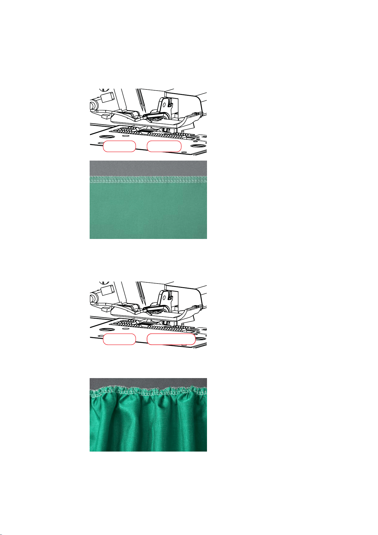
Gathering/Gather to fit "1.5 – 2"
At a setting of 1.5 - 2 the front feed dog (2) covers a longer distance than the rear feed dog (1).
1 2
Gathering
> To gather intentionally, increase the differential feed to a value between 1.5 and 2.
Machine Settings
51
2023-06 EN 5040064.10A.04
Gather to Fit
> To prevent waving increase the differential feed to a value between 1 and 2.
Stretching "0.6"
The front feed dog (0.6) covers a shorter distance than the rear feed dog (1). The material is stretched under
the presser foot which helps to reduce puckering. This setting can also be used to deliberately stretch the
material.
1 0.6
> To prevent seam puckering, reduce the differential feed to a value between 0.6 and 1.
Machine Settings
52
2023-06 EN 5040064.10A.04
6.9 Setting the Stitch Length
The stitch length can be infinitely adjusted between 1.0 – 5.0mm while sewing.
> To elongate the stitch, set the stitch length knob to a higher value.
> To shorten the stitch, set the stitch length knob to a lower value.
Threading
53
2023-06 EN 5040064.10A.04
7 Threading
This machine is equipped with an Air Threader System, which quickly and easily threads the Upper and the
Lower Looper Threads by pressing the threader button. There is no specific sequence required for threading
the Looper Threads.
The Needle Threads must be threaded according to a defined threading sequence.
> Thread the right Overlock Needle Thread before the left Overlock Needle Thread.
7.1 Threading preparation
Before threading, make sure that the device is mechanically adjusted to the required stitch. Perform the
required mechanical settings e.g. for needle, Rolled Hem Selection Lever or Upper Looper Cover.
Prerequisite:
• Retractale Thread Guide fully extended.
• The needles are at the top position.
• All threads that are not needed for the particular stitch have been removed.
> Raise the presser foot.
– The Thread Tensions are released and the thread can be inserted without resistance.
Threading
54
2023-06 EN 5040064.10A.04
> Place the thread cones on the respective spool pin.
> Place the thread from the back through the Thread Guide.
> Engage the thread in the Thread Pretension.
> Place the thread along the Threading Path between the Thread Tension Discs.
7.2 Air Threader
The Lower Looper Thread (red) is needed for each stitch. Depending on the stitch, the Upper Looper Thread
(blue) must be additionally threaded.If the upper looper thread is not used, the upper looper thread cover
must be attached.
NOTICE
Damage by coated or waxed threads
Coated or waxed threads may lose some of their coating in the Air Threader Pipes, which results in
permanent blocking of the pipes. A repair by the Authorized bernette dealer is required.
Avoid the use of coated or waxed threads.
> Threading the Looper Threads
Detailed information can be found in the stitch chart.
Threading
55
2023-06 EN 5040064.10A.04
Threading the Looper Threads UL/blue, LL/red
Due to the Air Threader all of the Looper Threads can be threaded in one step.
Prerequisite:
• (see page53)
• Threader Cover is opened.
• Upper Looper Cover hooked in/hooked out is checked.
> Set the Air Threader Connector to the left position.
> Slowly turn the Handwheel counterclockwise until the Air Threader Pipes couple.
> Feed the thread through the Thread Guide.
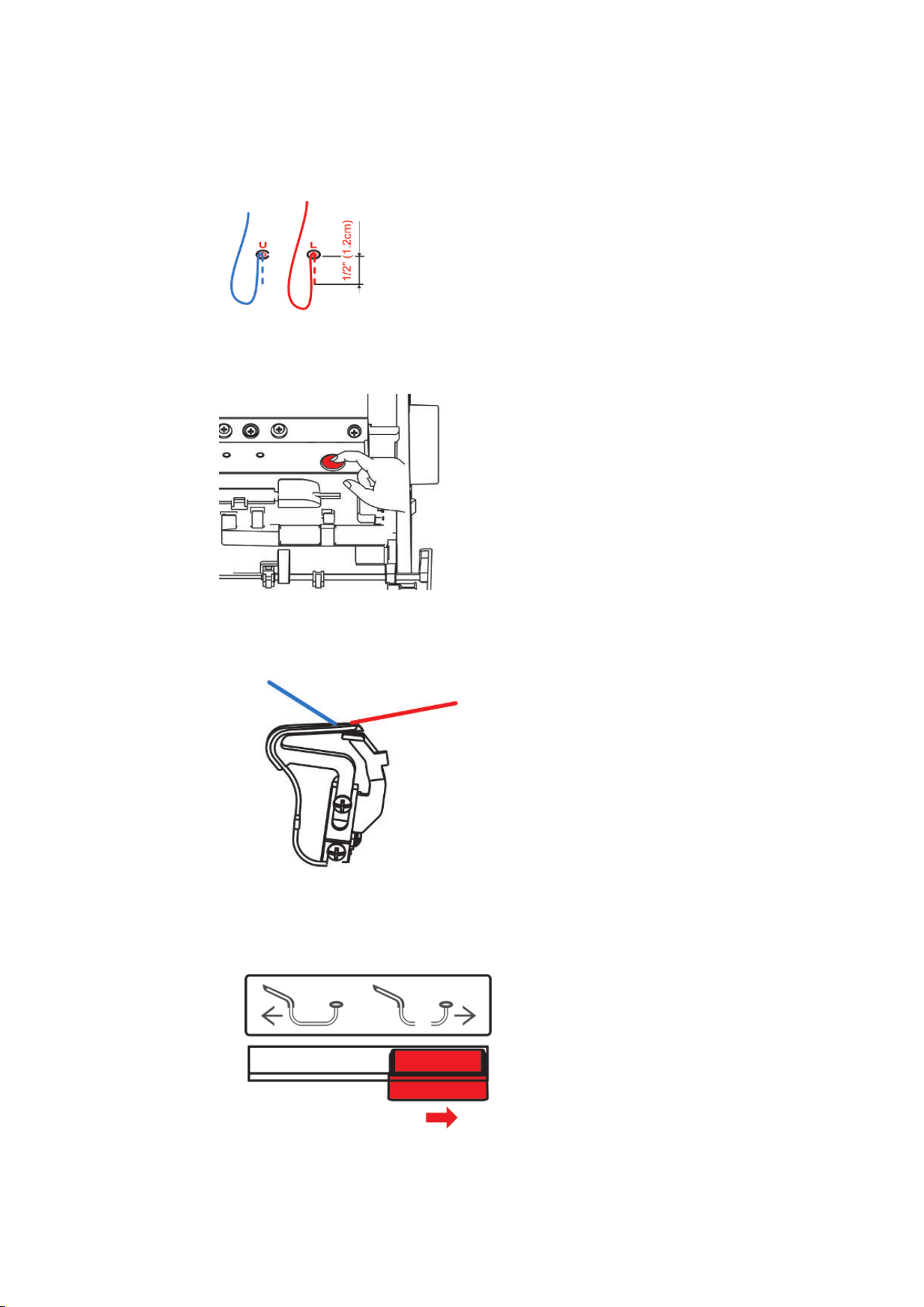
> Pull a thread reserve of approx. 56 cm so that the thread can be completely drawn through the Air
Threader Pipe.
Threading
56
2023-06 EN 5040064.10A.04
> Place the end of the thread approx. 1.2 cm into the corresponding Air Threader Nozzle.
> Press and hold the Air Threader Button.
– The automatic thread feed into the Air Threader starts.
– The Looper Thread is shot through the Air Threader Pipe and exits at the Looper Tip.
> As soon as the Looper Thread exits out of the Looper Eye, release the Air Threader Button.
> Place the Looper Thread under the presser foot to the back left.
> Repeat the process with the other Looper Thread if required.
> Set the Air Threader Connector to the right position.
> Close the Threader Cover.

Threading
57
2023-06 EN 5040064.10A.04
Threading the Looper Thread with an auxiliary thread
The use of an auxiliary thread makes sense if a Looper Thread cannot be threaded automatically with the Air
Threader.
Prerequisite:
• (see page53)
> Open the Threader Cover.
> Set the Air Threader Connector to the «left position».
> Prepare an auxiliary thread at a length of about 60 cm.
> Fold the auxiliary thread in half, hold the thread end with the loop in your hand and position the two
thread ends above the respective Air Threader Nozzle.
> Start the Air Threader Process until the thread ends of the auxiliary thread emerge out of the Looper Eye.
> Place the Looper Thread end at the length of about 20 cm through the loop of the auxiliary thread.
> Pull the auyiliary thread ends until the thread comes out of the Looper Eye.
> Remove the auxiliary thread.
> Place the Looper Thread under the presser foot to the back left.
Using the Threading Wire
The supplied Threading Wire can be used as a threading aid for the Looper Thread. The Threading Wire is a
wear part and not designed as a permanent threading or cleaning aid.
NOTICE
Damage by improper use of the Threading Wire
The Air Threader Pipes may be damaged. A repair by the Authorized bernette dealer is required.
> Insert and pull through the Threading Wire only in the thread flow direction.
Prerequisite:
• There is no thread in the respective Air Threader Pipe.
• «Threading preparation» (see page53)
> Open the Threader Cover.
> Guide the Threading wire with the end without loop through the corresponding Air Threader Nozzle
until it exits at the Looper Eye.
> Place the wanted thread through the loop of the Threading Wire.
> Pull the end of the Threading Wire until the Looper Thread exits from the Looper Eye.
> Place the Looper Thread under the presser foot to the back left.
> Close the Threader Cover.
Any malfunctions of the Air Threader System must be repaired by an Authorized BERNINA dealer.
Threading
58
2023-06 EN 5040064.10A.04
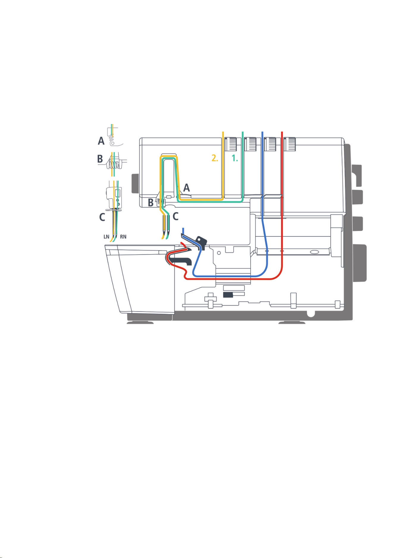
7.3 Threading the needle thread
For the needles inserted in the needle holder, color-coded threading paths are assigned.
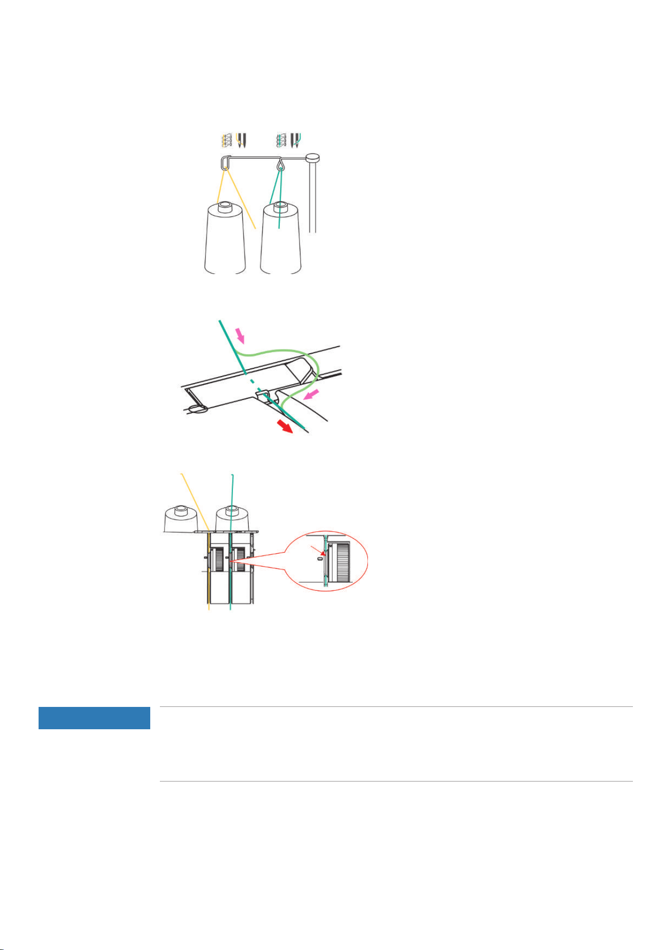
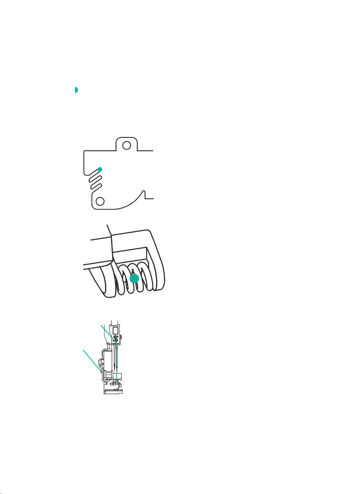
Threading the Right Needle Thread RN/green
The Right Needle Thread Path is marked green.
Prerequisite:
• (see page53)
> Pull the thread beneath the Thread Guide Plate to the left and up between the backmost opening of the
Thread Deflection Finger.
> Place the thread over the Needle Thread Take-up Lever Cover and pull it down.
> Insert the thread into the right Thread Guide.
> Hook the thread into the right Thread Guide at the Needle Holder.
> Thread the Right Overlock Needle (RN).
> Place the thread beneath the presser foot to the back left.
Threading
59
2023-06 EN 5040064.10A.04
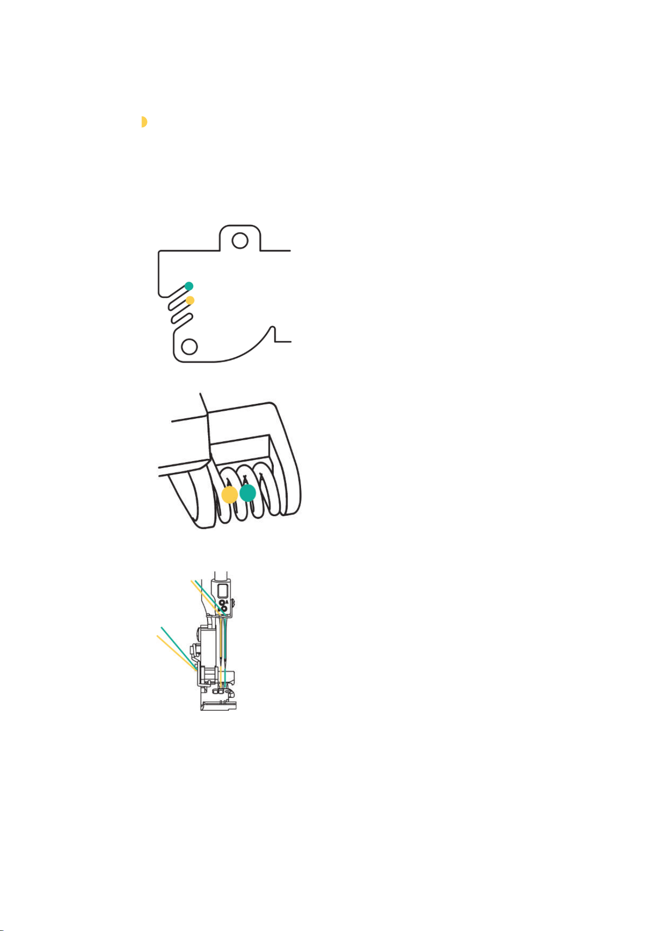
Threading the Left Needle Thread LN/yellow
The Left Needle Thread Path is marked yellow.
Prerequisite:
• The Right Needle Thread is threaded.
• The «Threading preparation» has been performed. (see page53)
> Pull the thread beneath the Thread Guide Plate to the left and up through the center opening of the
Thread Deflection Finger.
> Place the thread over the Needle Thread Take-up Lever Cover and pull it down.
> Insert the thread into the left Thread Guide.
> Hook the thread into the left Thread Guide at the Needle Holder.
> Thread the Left Overlock Needle (LN).
> Place the thread beneath the presser foot to the back left.
Threading
60
2023-06 EN 5040064.10A.04
7.4 Thread change
Knotting thick thread
Tying on threads is often used for changing needle thread or Looper threads. (see page61)
Keep the knotted area as little as possible to reduce friction.
NOTICE
Pulling a Thread Tie through the Needle Eye
The needle can be bent. A bent needle affects the stitch formation.
> Cut the tie in front of the needle eye and thread the needle individually.
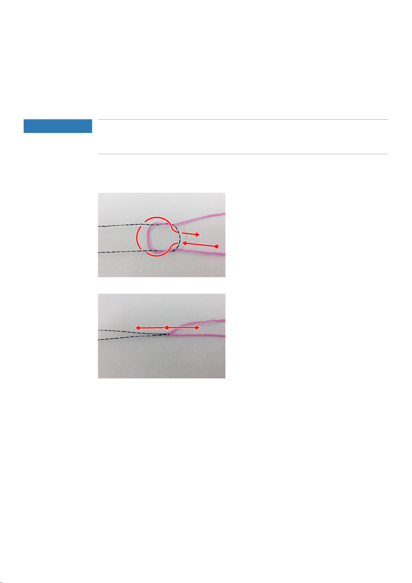
> Form a loop with the dark thread.
> Thread the pink thread end from beneath into the dark thread loop.
> Guide the pink thread to the back around the two dark threads and from above through the loop.
> Hold both thread ends and pull them apart.
Threading
61
2023-06 EN 5040064.10A.04
Changing the needle thread
NOTICE
Pulling a Thread Tie through the Needle Eye
The needle can be bent. A bent needle affects the stitch formation.
> Cut the tie in front of the needle eye and thread the needle individually.
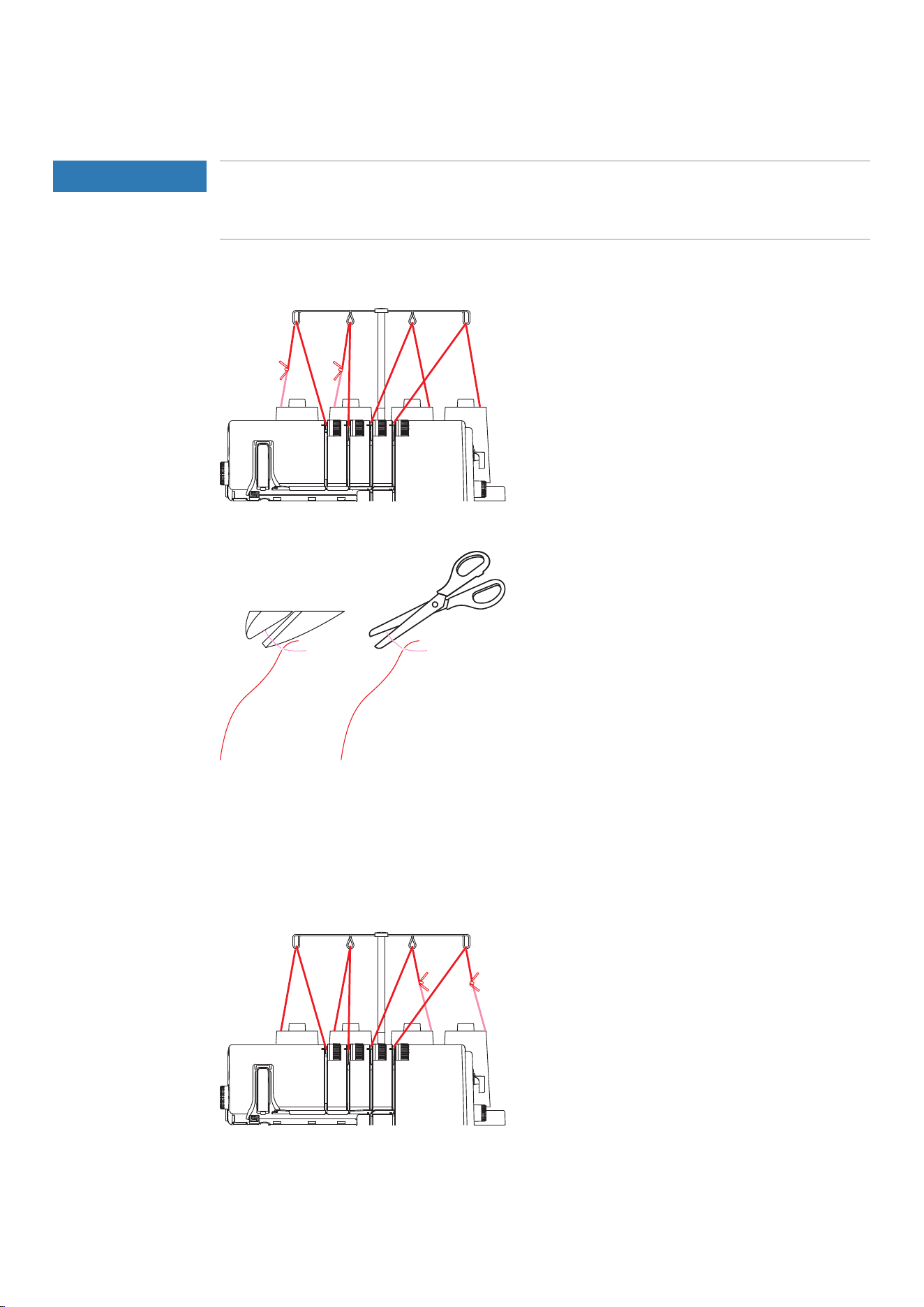
> Cut the thread above the thread cone.
> Change the thread cone.
> Tie the threaded thread to the new thread.
> Pull the threaded end of the thread until the newly knotted thread is in front of the needle eye.
> Cut off the new thread behind the knotting.
> Remove the excess thread from the eye of the needle.
> Thread the needle eye.
> Place the thread beneath the presser foot to the back left.
Changing the looper thread
> Cut the thread above the thread cone.
> Change the thread cone.
> Tie the inserted Looper Thread to the new thread.
> Pull the end of the thread out of the Looper Eye until the knot emerges.
> Cut off the new thread behind the knotting.
> Place the thread under the presser foot to the left.

Sewing Test
62
2023-06 EN 5040064.10A.04
8 Sewing Test
To check the optimal setting, a sewing test should be sewn on a spare piece of the fabric used for your
project.
The default values of the stitches represent recommendations that work for most standard applications.
Depending on the sewing test, fine adjustments for stitch optimization are possible.
8.1 Perfoming a Sewing Test for an Overlock Stitch
Prerequisite:
• (see page33)
> Place the fabric under the presser foot to the front of the knife so that the desired seam allowance is cut
off.
> Press the Foot Control and sew slowly. Guide the fabric gently as the machine automatically transports
the material.
> Sew beyond the fabric end such that a thread chain is formed.
> Pull the thread chain over the Thread Cutter.
> Assess the sewing test and make any necessary adjustments until the stitch setting matches the material
combination.
8.2 Optimizing stitches
Optimizations of stitches should be made systematically. In the following, recommendations are listed for
each stitch type, which optimize the stitch pattern through specific changes to the machine setting.
> Perform one action step after another, starting from the top.
> Reduce the Thread Tension in the first place before increasing the Thread Tension.
> Alter the Thread Tensions only by half or one digit at a time.
> Perform a sewing test.
Sewing Test
63
2023-06 EN 5040064.10A.04
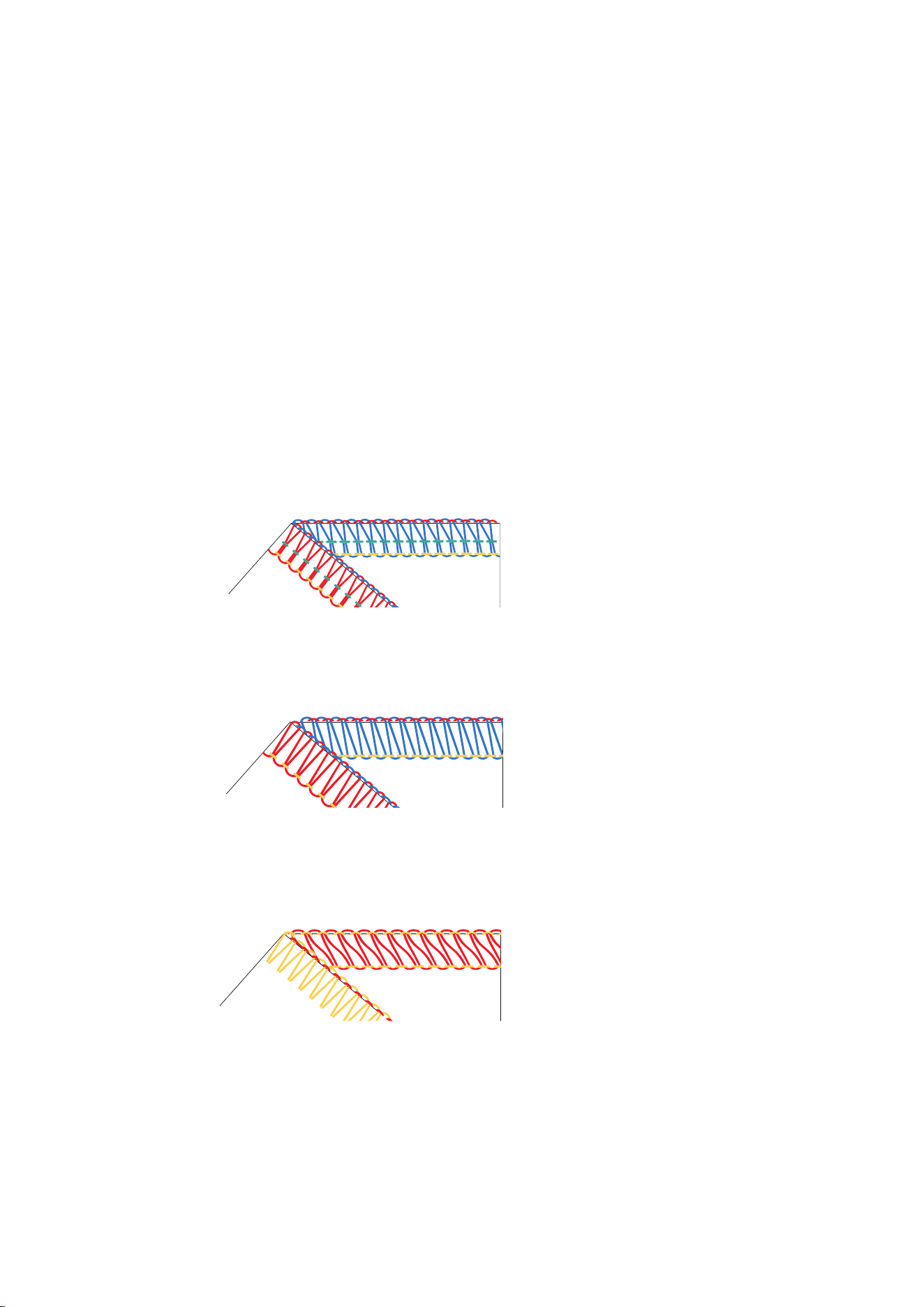
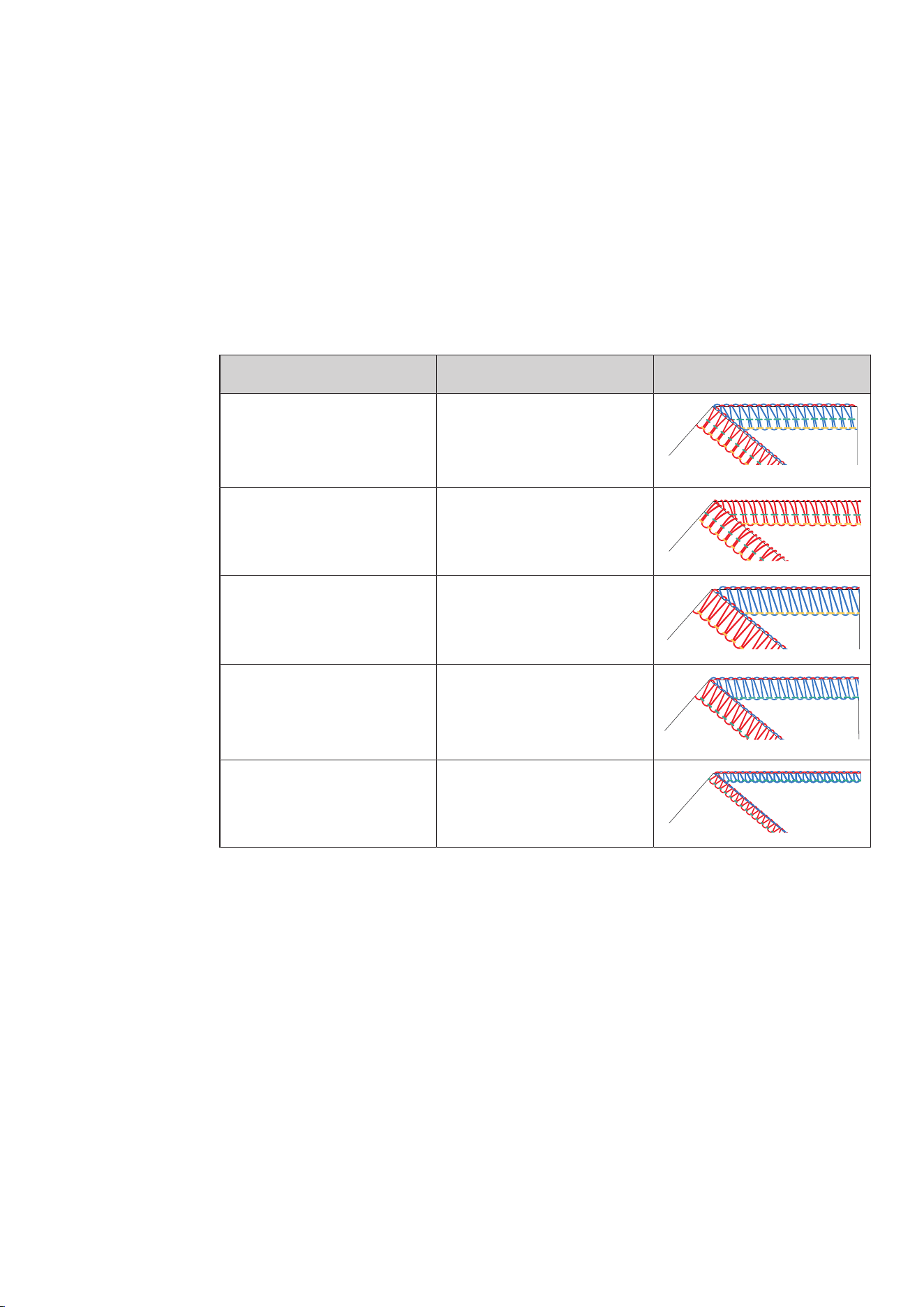
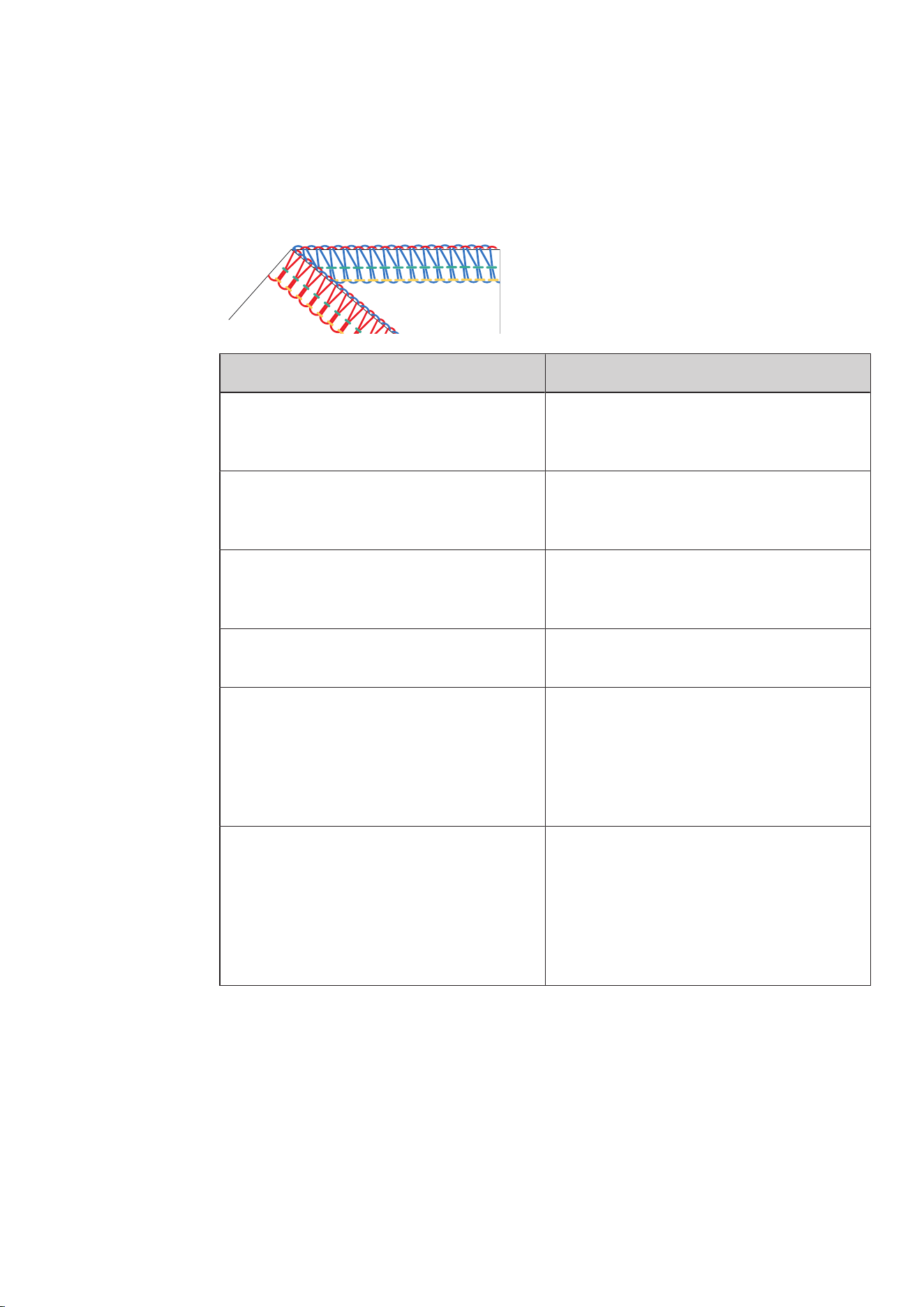
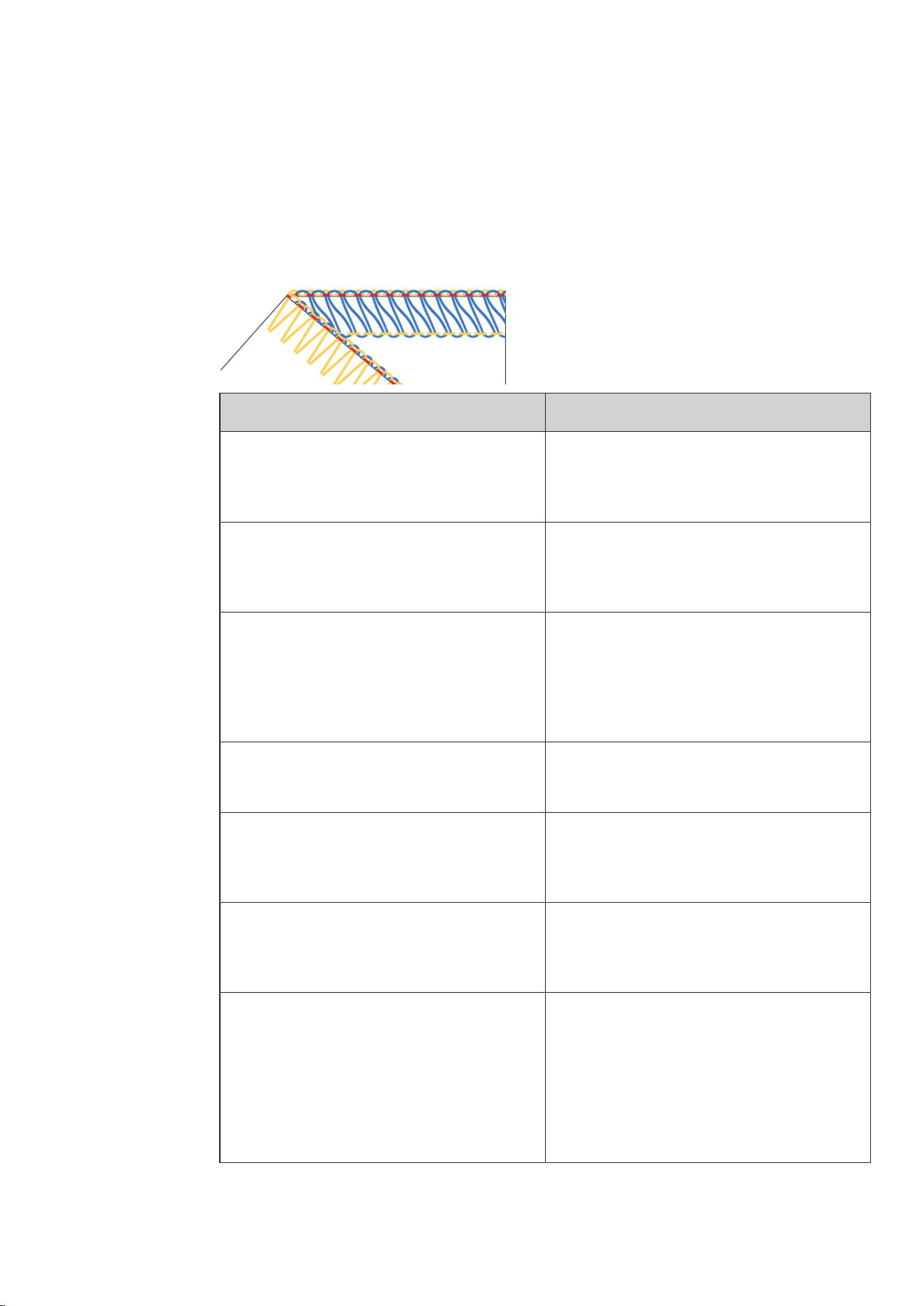
4-/3-thread Overlock
With a balanced stitch formation, the Looper Thread (blue/red) are intertwined at the fabric edge.
The Needle Threads (green/yellow) create two straight lines of stitches on the right side of the stitch and
appear as dots on the wrong side of the stitch.
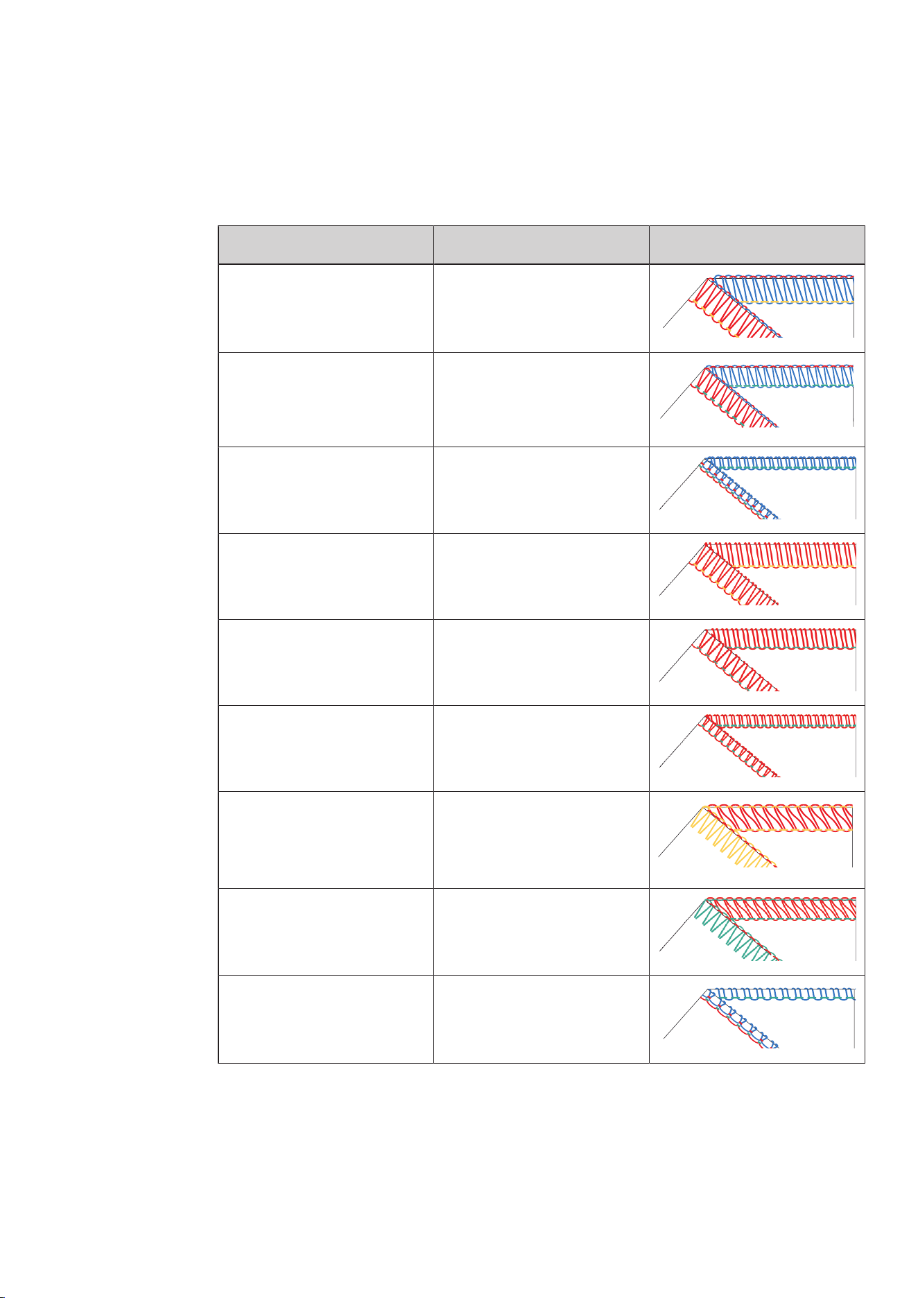
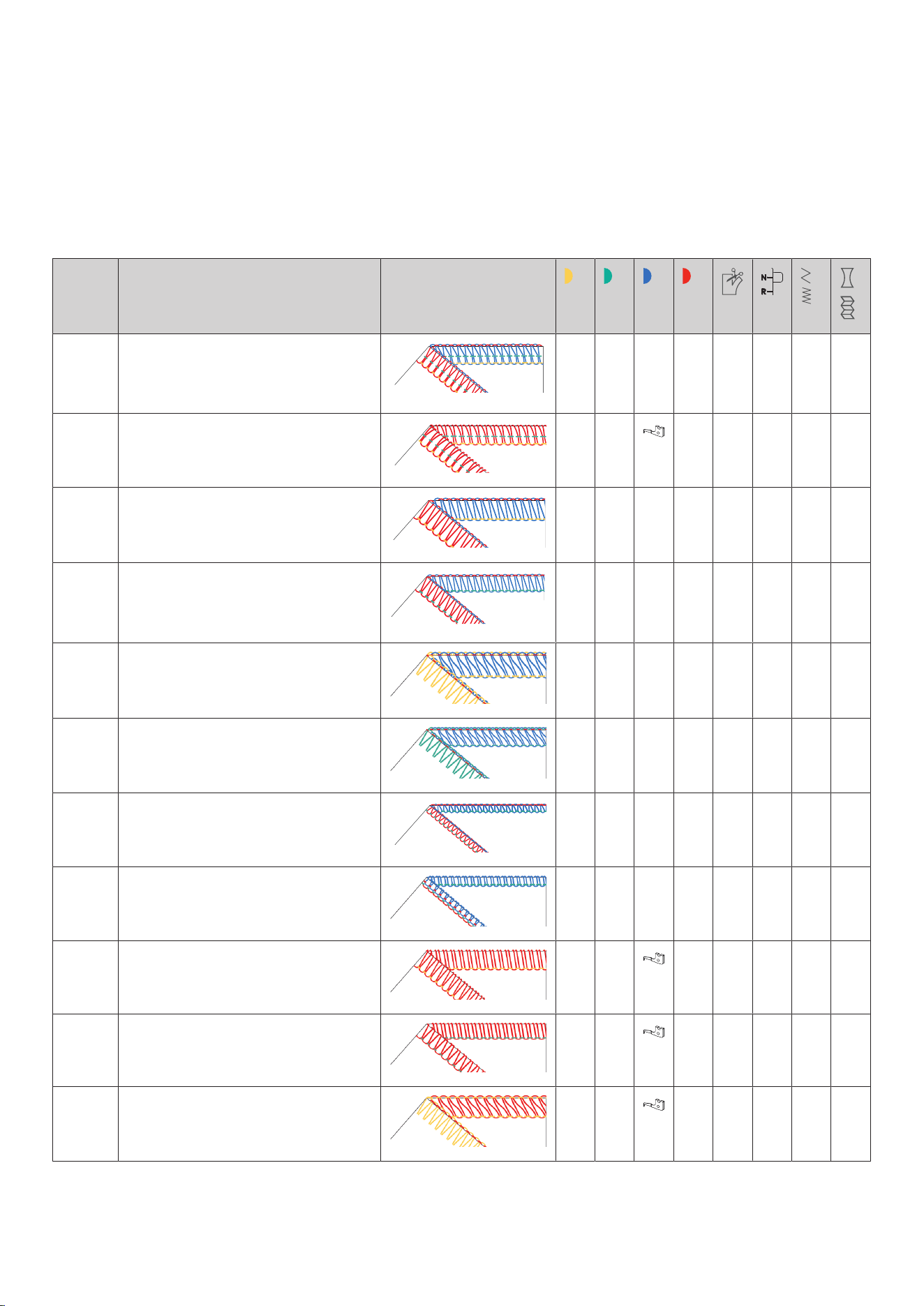
Stitch pattern Solution
The Looper Threads are intertwined on the
wrong side of the fabric.
> Reduce the Lower Looper Thread Tension (red).
> Increase the Upper Looper Thread Tension
(blue).
The Looper Threads are intertwined on the
right side of the fabric.
> Reduce the Upper Thread Tension (blue).
> Increase the Lower Looper Thread Tension
(red).
The Left Needle Thread forms loops on the
wrong side of the fabric.
> Increase the Left Needle Thread Tension
(yellow).
> Reduce the Lower Looper Thread Tension (red).
The Right Needle Thread forms loop on the
wrong side of the fabric.
> Increase the Right Needle Thread Tension
(green).
The fabric edge curls.
> Reduce the Upper Thread Tension (blue).
> Reduce the Lower Looper Thread Tension (red).
> Increase the mtc Mircro Thread Control.
> Reduce the Cutting Width «CW».
> Check the Rolled Hem Selection Lever position
«N».
The seam puckers.
> Reduce the Left Needle Thread Tension
(yellow).
> Increase the Right Needle Thread Tension
(green).
> Set the Differential Feed between 1 and 0.6
(Stretching).
> Shorten the Stitch Length «SL».
Tab.1: Optimizing the stitch: 4-/3-thread overlock

Sewing Test
64
2023-06 EN 5040064.10A.04
3-Thread Narrow Seam
With a balanced stitch formation, the looper thread (blue/red) are intertwined at the fabric edge.
The needle thread (green) is identifiable on the top side of the stitch as a straight line and on the bottom side
of the stitch as points.
Stitch pattern Recommendation
The looper threads are intertwined on the
wrong side of the fabric.
> Reduce the lower looper thread tension (red).
> Increase the upper looper thread tension (blue).
The looper threads are intertwined on the
right side of the fabric.
> Reduce the upper thread tension (blue).
> Increase the lower looper thread tension (red).
The right needle thread forms loop on the
wrong side of the fabric.
> Increase the right needle thread tension
(green).
The fabric edge doesn't curl as intended.
> Increase the upper looper thread tension (blue).
> Increase the lower looper thread tension (red).
> Increase the cutting width «CW».
> Shorten the stitch length «SL».
> Check the rollhem selector lever position «R».
Tab.2: Optimizing the stitch: 3-Thread Narrow Seam
Sewing Test
65
2023-06 EN 5040064.10A.04
3-thread super-stretch / 2-thread wrapped overlock
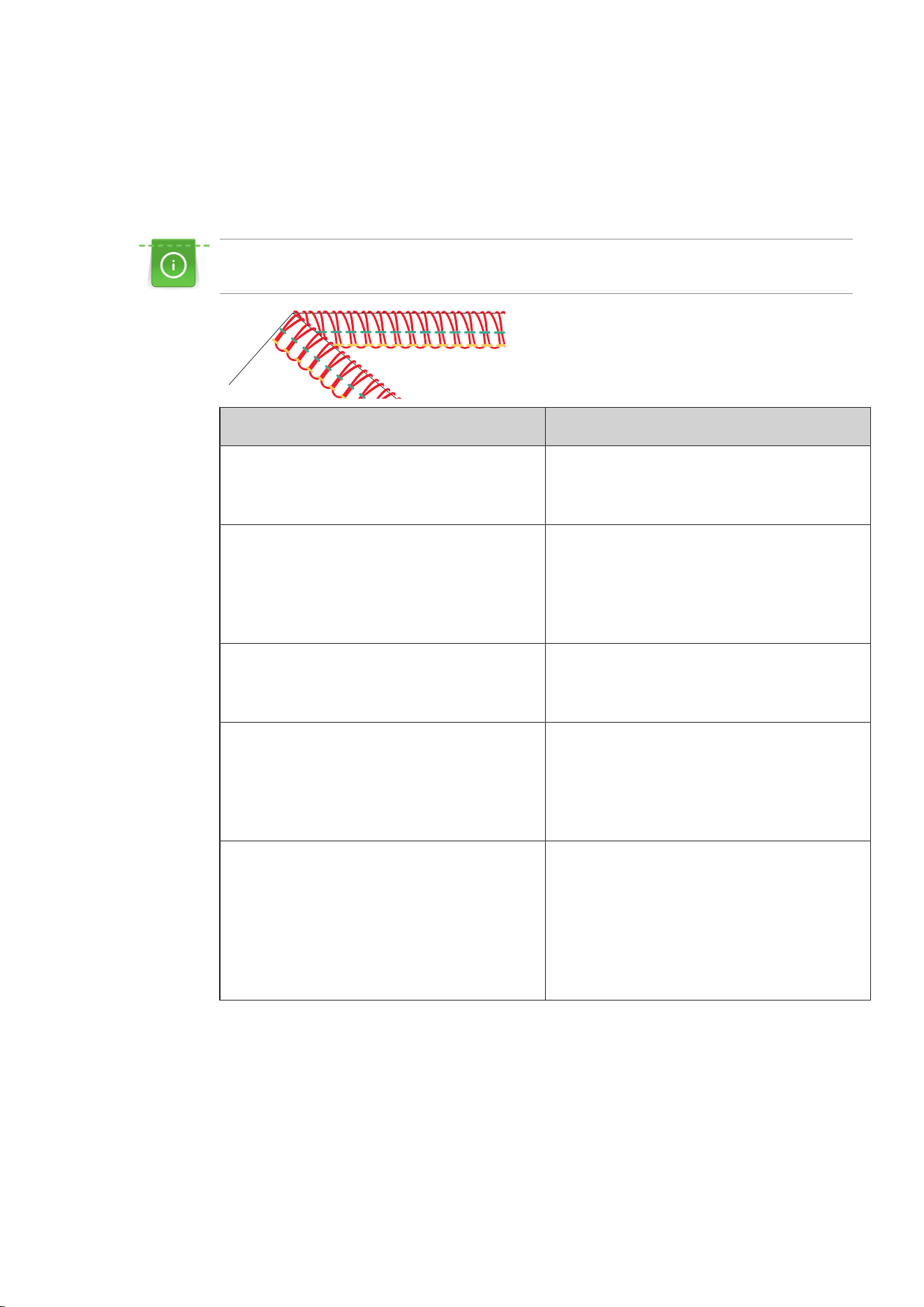
With a balanced stitch formation, the Looper Thread (red) loops around the cutting edge.
The Needle Threads (green/yellow) create two straight lines of stitches on the right side of the stitch and
appear as dots on the wrong side of the stitch.
The elasticity of the 3-thread super-stretch can be increased by shortening the stitch length or by
reducing the Needle Thread Tension depending on the material and application.
Stitch pattern Solution
The Looper Thread is too loose around the
fabric edge.
> Increase the Lower Looper Thread Tension
(red).
> Increase the mtc Mircro Thread Control.
The Looper Thread is too tight around the
fabric edge.
> Reduce the Lower Looper Thread Tension (red).
> Increase the mtc Mircro Thread Control.
> Reduce the Cutting Width «CW».
> Check the Rolled Hem Selection Lever position
«N».
The Needle Thread forms loops on the wrong
side of the fabric.
> Increase the Needle Thread Tension (yellow,
green).
> Reduce the Lower Looper Thread Tension (red).
The fabric edge forms a tunnel or curls.
> Reduce the Lower Looper Thread Tension (red).
> Increase the mtc Mircro Thread Control.
> Reduce the Cutting Width «CW».
> Check the Rolled Hem Selection Lever position
«N».
The seam puckers.
> Reduce the Left Needle Thread Tension
(yellow).
> Increase the Right Needle Thread Tension
(green).
> Set the Differential Feed between 1 and 0.6
(Stretching).
> Shorten the Stitch Length «SL».
Tab.3: Optimizing the stitch: 3-thread super-stretch / 2-thread wrapped overlock
Sewing Test
66
2023-06 EN 5040064.10A.04
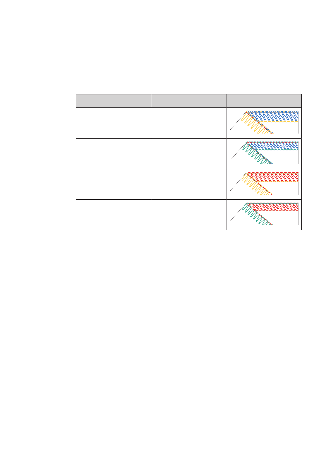
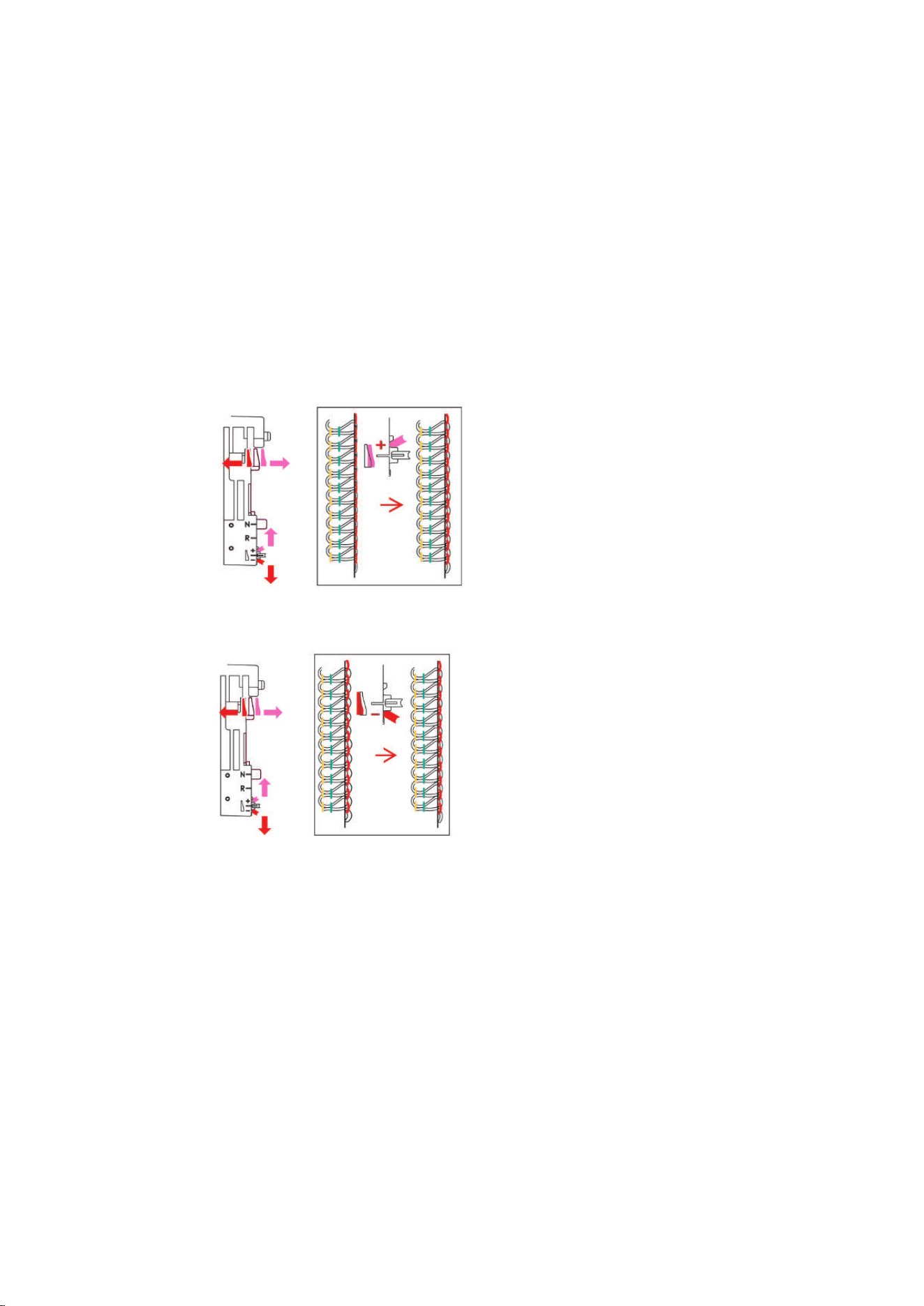
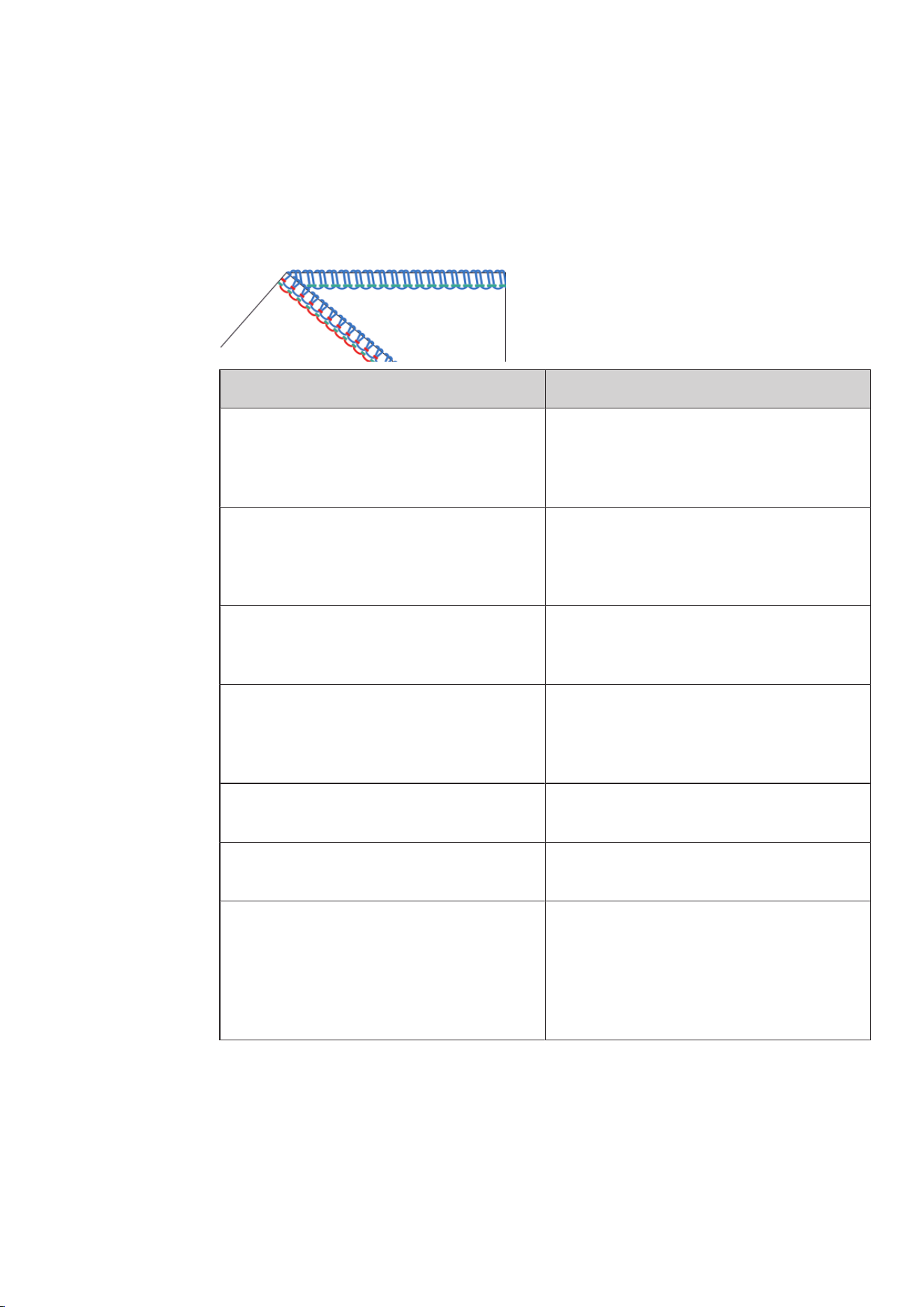
3-thread flatlock
With a balanced stitch formation, the upper thread (blue) is on the right side of the stitch related to the
insertion into the fabric edge.
The Lower Looper Thread (red) is parallel to the fabric edge.
The Needle Thread (yellow or green) forms a «V» on the wrong side of the stitch related to the insertion into
the fabric edge.
Stitch pattern Solution
The Lower Looper Thread overedges the
fabric edge towards the wrong side of the
fabric.
> Reduce the Needle Thread Tension (yellow or
green).
> Increase the Upper Looper Thread Tension
(blue).
The Upper Looper thread doesn't reach to the
fabric edge.
> Increase the Needle Thread Tension (yellow or
green).
> Reduce the Upper Looper Thread Tension
(blue).
The Lower Looper thread is not parallel to the
fabric edge.
> Increase the Lower Looper Thread Tension
(red).
> Reduce the Needle Thread Tension (yellow or
green).
> Reduce the Upper Looper Thread Tension
(blue).
The seam puckers, the Lower Looper Thread is
overstretched.
> Reduce the Lower Looper Thread Tension (red).
The Needle Thread doesn't reach to the fabric
edge.
> Reduce the Needle Thread Tension (yellow or
green).
> Increase the Upper Looper Thread Tension
(blue).
The Lower Looper Thread overedges the
fabric edge towards the wrong side of the
fabric.
> Increase the Needle Thread Tension (yellow or
green).
> Reduce the Upper Looper Thread Tension
(blue).
The fabric edge curls.
> Reduce the Needle Thread Tension (yellow or
green).
> Reduce the Upper Looper Thread Tension
(blue).
> Increase the mtc Mircro Thread Control.
> Reduce the Cutting Width «CW».
> Check the Rolled Hem Selection Lever position
«N».
Tab.4: Optimizing the stitch: 3-thread flatlock
Sewing Test
67
2023-06 EN 5040064.10A.04
3-thread rolled hem / 3-thread picot stitch
With a balanced stitch formation, the upper looper thread (blue) loops around the cutting edge.
The Lower Looper thread (red) lies straight along the needle thread on the wrong side of the stitch.
The Needle Thread (green) is identifiable on the right side of the stitch as a straight line and on the wrong
side of the stitch as points.
Stitch pattern Solution
The Looper Thread is too loose around the
fabric edge.
> Increase the Upper Looper Thread Tension
(blue).
> Increase the Cutting Width «CW».
> Shorten the Stitch Length «SL».
The fabric edge doesn't curl as intended.
> Increase the Cutting Width «CW».
> Increase the Upper Looper Thread Tension
(blue).
> Elongate the Stitch Length «SL».
The Upper Looper Thread is too tight around
the fabric edge.
> Reduce the Upper Looper Thread Tension
(blue).
> Shorten the Stitch Length «SL».
The Lower Looper Threads are not parallel to
the needle thread.
> Increase the Lower Looper Thread Tension
(red).
> Increase the Right Needle Thread Tension
(green).
The seam puckers, the Lower Looper Thread is
overstretched.
> Reduce the Lower Looper Thread Tension (red).
The needle thread forms loops on the wrong
side of the fabric.
> Increase the Right Needle Thread Tension
(green).
The seam puckers.
> Reduce the Lower Looper Thread Tension (red).
> Set the Differential Feed between 1 and 0.6
(Stretching).
> Increase the Right Needle Thread Tension
(green).
> Shorten the Stitch Length «SL».
Tab.5: Optimizing the stitch: 3-thread rolled hem / 3-thread picot stitch
Sewing Test
68
2023-06 EN 5040064.10A.04
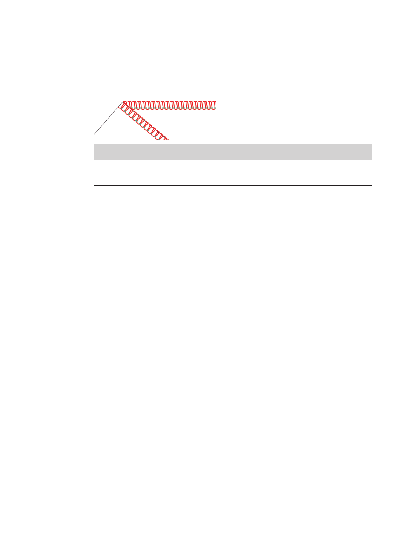
2-thread rolled hem
With a balanced stitch formation, the looper thread (red) loops around the cutting edge. The Needle Thread
(green) is identifiable on the right side of the stitch as a straight line and on the wrong side of the stitch as
points.
Stitch pattern Solution
The Looper Thread is too loose around the
fabric edge.
> Increase the Lower Looper Thread Tension
(red).
The Looper Thread is too tight around the
fabric edge.
> Reduce the Lower Looper Thread Tension (red).
> Reduce the Cutting Width «CW».
The fabric edge doesn't curl as intended.
> Increase the Cutting Width «CW».
> Elongate the Stitch Length «SL».
> Increase the Lower Looper Thread Tension
(red).
The Needle Thread forms loops on the wrong
side of the fabric.
> Increase the Right Needle Thread Tension
(green).
The seam puckers.
> Reduce the Right Needle Thread Tension
(green).
> Set the Differential Feed between 1 and 0.6
(Stretching).
> Shorten the Stitch Length «SL».
Tab.6: Optimizing the stitch: 2-thread rolled hem
Sewing Test
69
2023-06 EN 5040064.10A.04
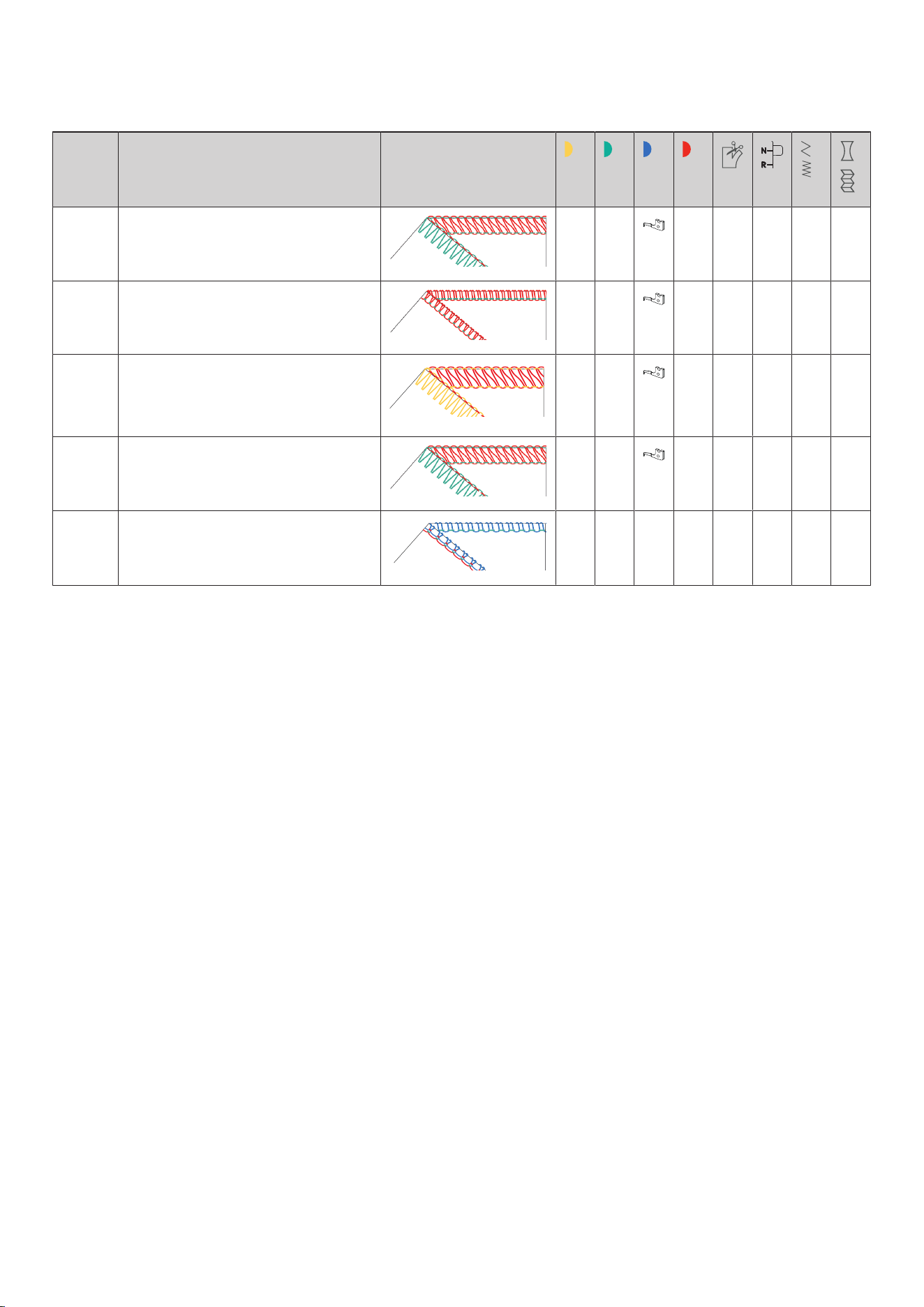
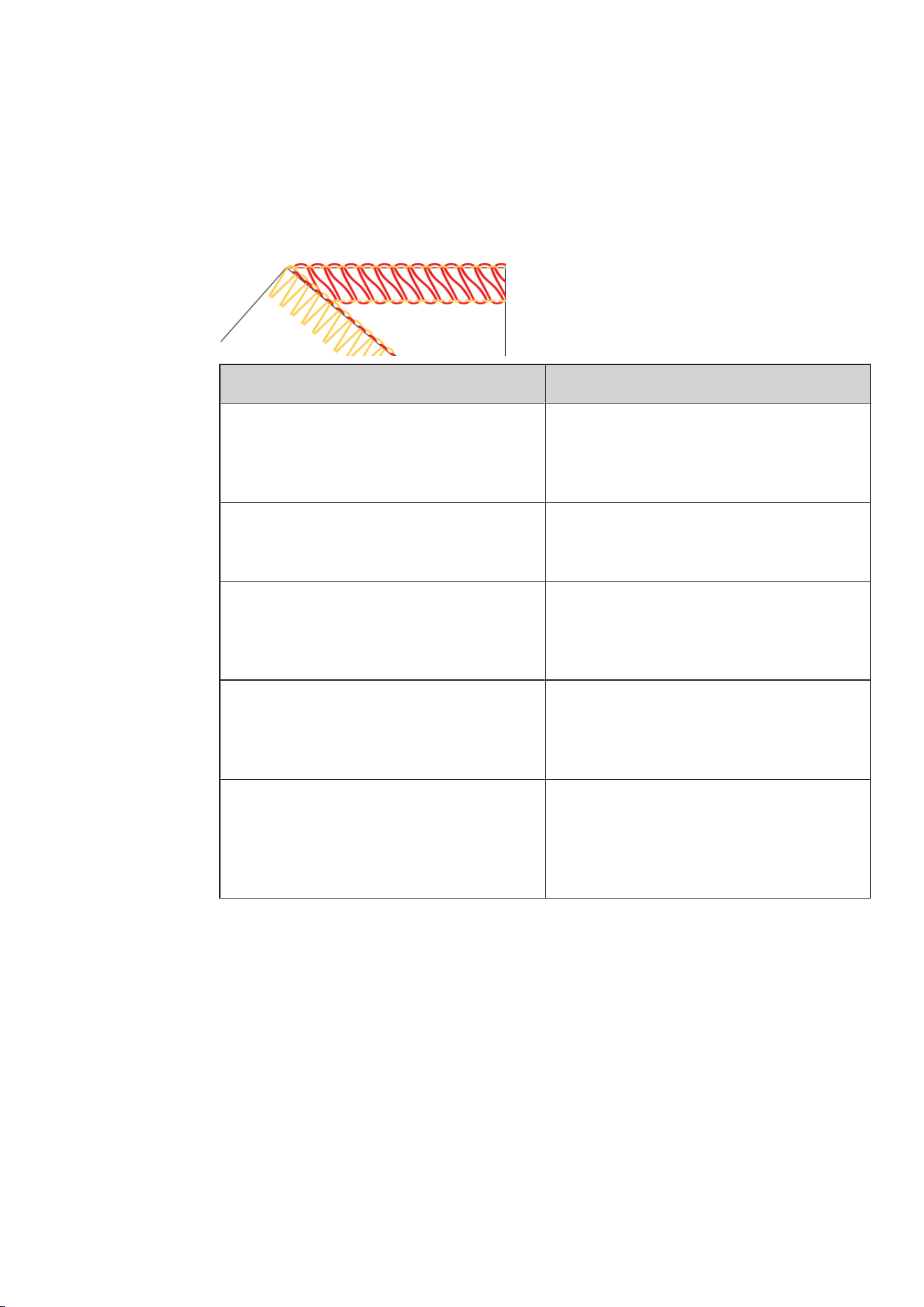
2-thread flatlock / 2-thread overlock
With a balanced stitch formation, the Lower Looper Thread (red) lies on the right side of the stitch from the
needle penetration point to the fabric edge.
The Needle Thread (yellow or green) forms a «V» on the wrong side of the stitch related to the insertion into
the fabric edge.
Stitch pattern Solution
The Lower Looper Thread overedges the
fabric edge towards the wrong side of the
fabric.
> Increase the Lower Looper Thread Tension
(red).
> Reduce the Needle Thread Tension (yellow or
green).
The lower looper thread doesn't reach to the
fabric edge.
> Reduce the Lower Looper Thread Tension (red).
> Increase the Needle Thread Tension (yellow or
green).
The Needle Thread doesn't reach to the fabric
edge.
> Increase the Lower Looper Thread Tension
(red).
> Reduce the Needle Thread Tension (yellow or
green).
The Lower Looper Thread overedges the
fabric edge towards the wrong side of the
fabric.
> Reduce the Lower Looper Thread Tension (red).
> Increase the Needle Thread Tension (yellow or
green).
The fabric edge forms a tunnel or curls.
> Increase the mtc Mircro Thread Control.
> Reduce the Cutting Width «CW».
> Shorten the Stitch Length «SL».
> Check the Rolled Hem Selection Lever position
«N».
Tab.7: Optimizing the stitch: 2-thread flatlock / 2-thread overlock
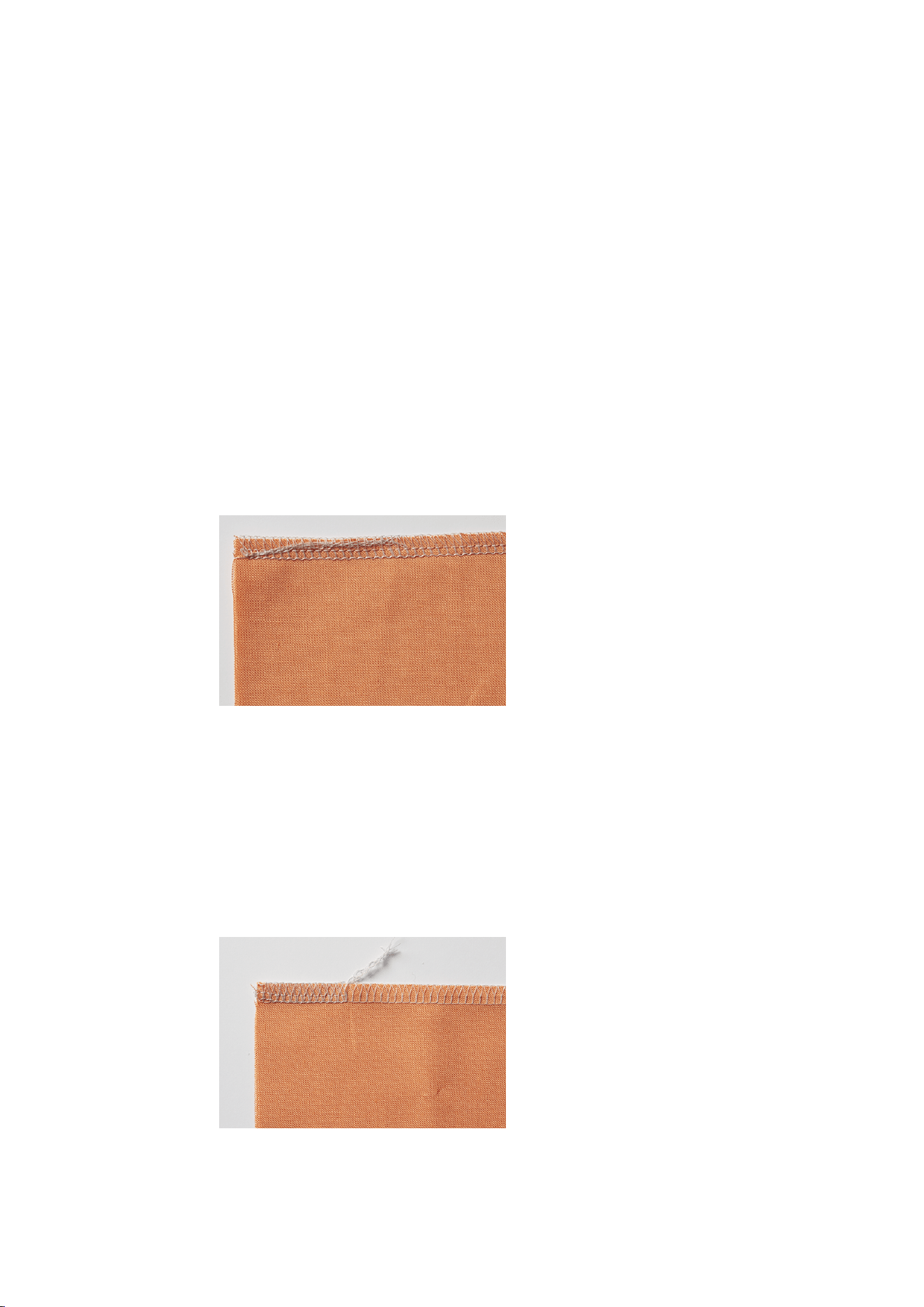
Practical Overlocking
70
2023-06 EN 5040064.10A.04
9 Practical Overlocking
In this chapter the most important applications for a successful sewing project are described. More advanced
sewing techniques are described in the BERNINA Overlocker Manual and can be purchased from Authorized
BERNINA dealers.
9.1 Securing Overlock Stitches
The stitches are secured when they are overstitched.
Securing stitches is particularly important when seam ends are not secured by other seams or hems.
Sewing in the Overlock Chain at the Start of the Seam
> Form a thread chain at a length of 5 - 8 cm.
> Place the fabric under the presser foot and sew a stitch into the fabric.
> Lower the needle .
> Raise the presser foot.
> Now pull the thread chain carefully forward and place it on the seam line to be sewn.
> Lower the presser foot.
> Sew approx. 4 cm over the thread chain.
Sewing in the Overlock Chain at the End of the Seam
> At the end of the seam, sew one stitch over the fabric edge.
> Raise the needle.
> Raise the presser foot.
> Pull the fabric a bit backwards.
> Turn the fabric so that the wrong side points upwards.
> Place the fabric beneath the presser foot so that the needles pierce the fabric at the first stitch.
> Lower the presser foot.
> Sew approx. 1.5 - 2.5 cm over the thread chain and make sure that the existing thread chain is not cut.
> Finish the seam by sewing off the edge.
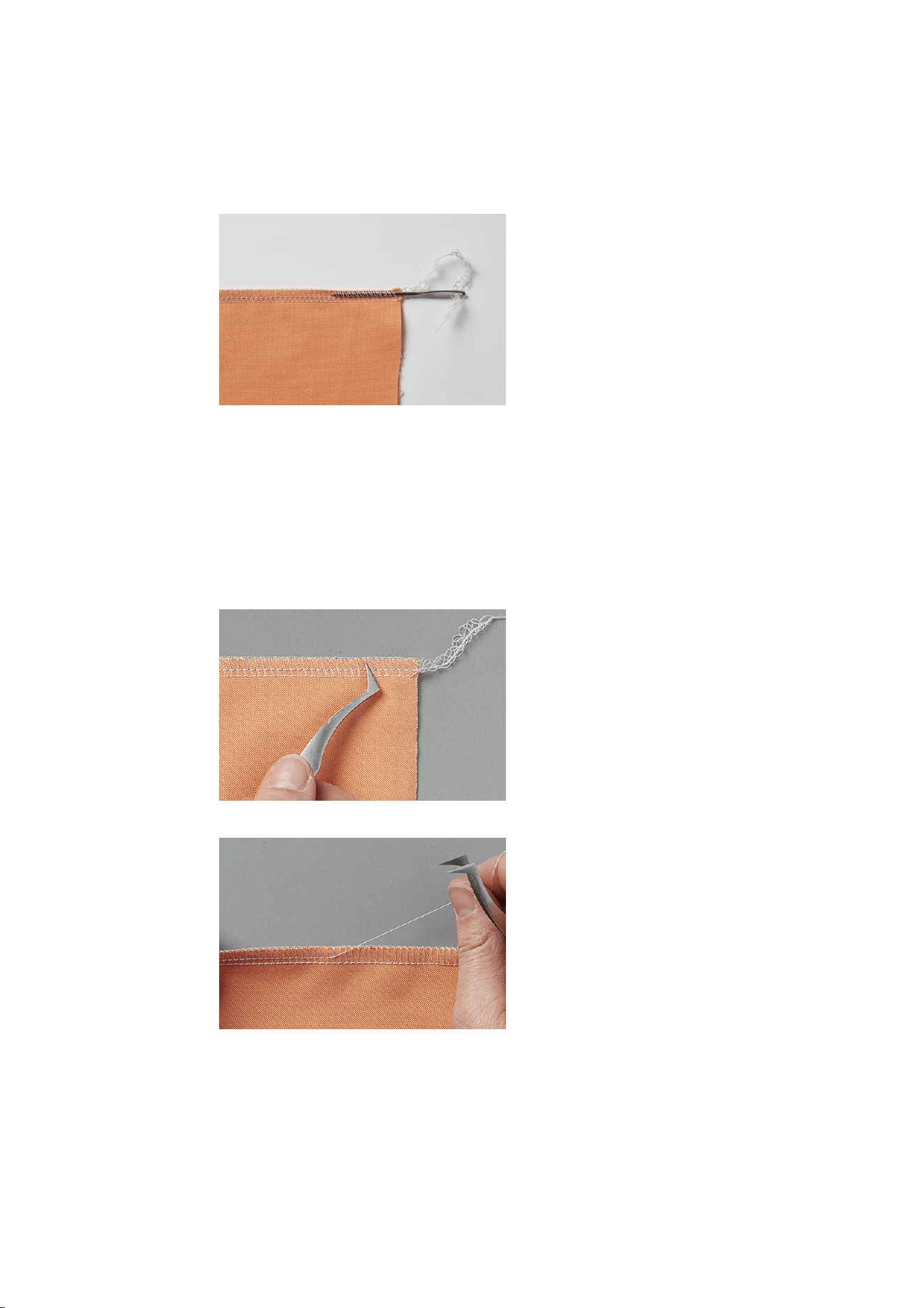
Practical Overlocking
71
2023-06 EN 5040064.10A.04
Securing Overlock Stitches
> Sew a thread chain of about 10 cm beyond the end of the seam.
> Pull the thread chain end through the looper threads using a loop flip or a tapestry needle.
Knotting the Overlock chain
Knotting the overlock chain is the safest way to prevent the stitch from opening.
> Tie thread chain at the seam end, close to the fabric.
9.2 Removing a Stitch
The thread loops of the looper and needle threads can be undone easily.
> Pull the right overlock needle thread (RN) out of the thread chain with tweezers, starting from the seam
end.
> Pull the needle thread out of the seam.
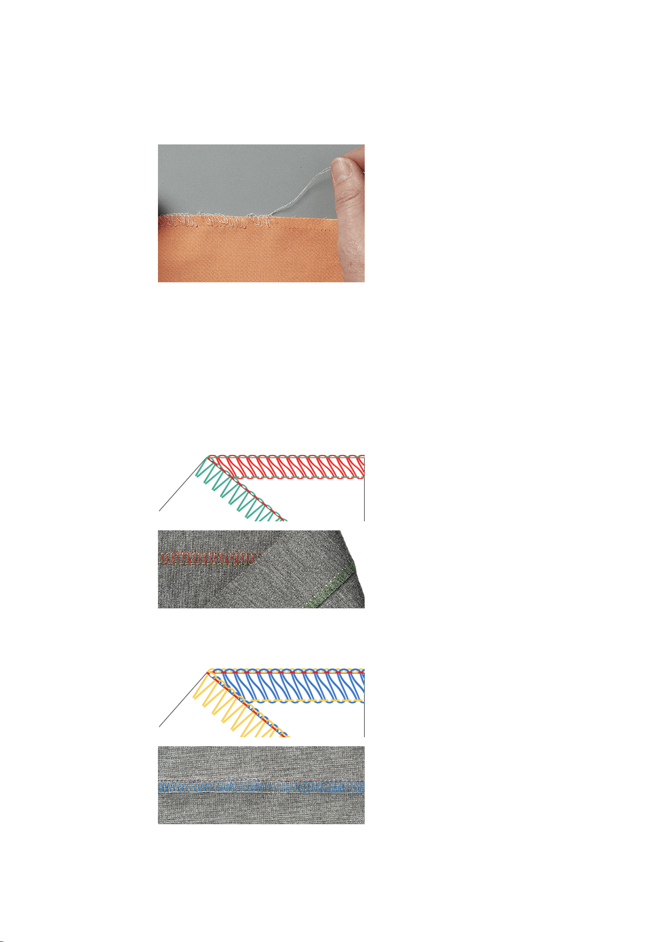
Practical Overlocking
72
2023-06 EN 5040064.10A.04
> With very long seams, cut the thread in the stitch and remove it step by step.
> Remove the left overlock needle thread in the same way.
– The looper threads lie loosely around the fabric edge and can be pulled away easily.
9.3 Flatlock
The flatlock forms loops on the upper side of the seam and stretch stitches on the underside.
> Set the machine for a 2- or 3-thread flatlock.
> Sew two layers of fabric together (wrong side on wrong side).
> Carefully separate the two layers of fabric.
– The two fabric edges now lie flat on top of each other at the stitch width of the flatlock.
Flatlock Narrow
A narrow flatlock is the result when the Right Overlock Needle (RN) is inserted.
Flatlock Wide
A wide flatlock is the result when the Left Overlock Needle (LN) is inserted.
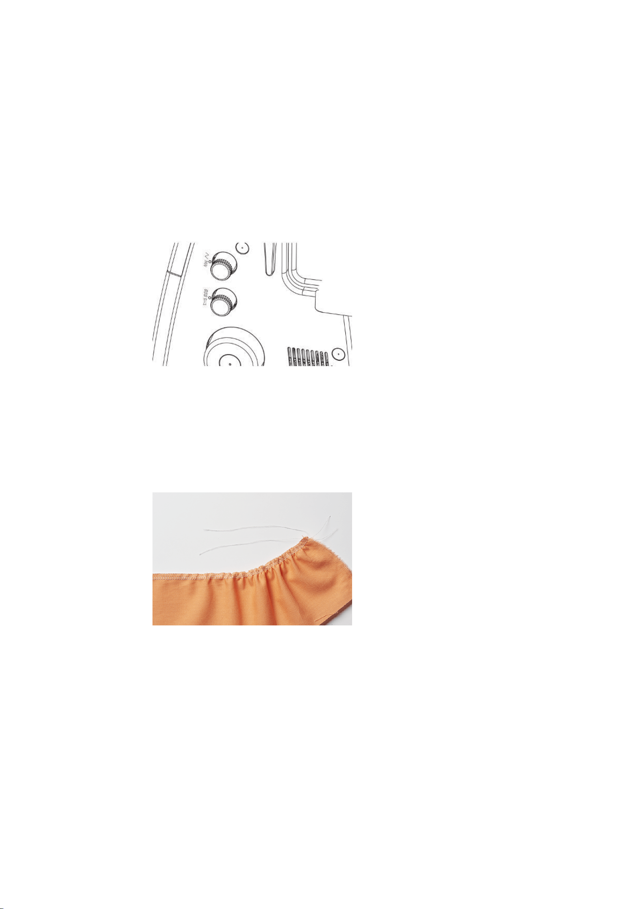
Practical Overlocking
73
2023-06 EN 5040064.10A.04
9.4 Gathering
Ruffling is a gathering or puckering of a seam.
Increasing the differential feed
> Set the machine for a 4-thread overlock.
> Set the Differential Feed to «2».
> Set the stitch length to «4.5».
> Sew the fabric with this side up on which the ruffling is wanted.
> Sew off the edge of the fabric.
Pulling the Needle Thread
> Set the machine for a 4-Thread Overlock.
> Set the differential feed at default value.
> Sew the fabric with this side up on which the ruffling is wanted.
> Leave a long thread chain at seam end.
> Separate the needle thread/threads from the thread chain.
> Pull the needle thread(s) and evenly spread the puckers along the seam.
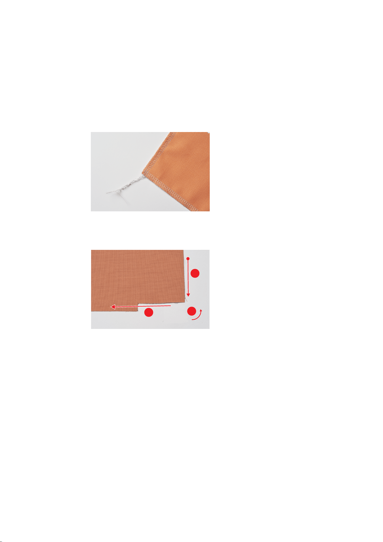
Practical Overlocking
74
2023-06 EN 5040064.10A.04
9.5 Sew Outer Corners
A neat corner can be achieved by the following two methods.
Method 1
> Set the machine for a 2-, 3- or 4-thread overlock.
> Sew along the edge of the fabric beyond the corner.
> Start a new edge and sew over the previously sewn edge.
> Secure the thread chain. (see page71)
Method 2
> Trim the seam allowance for the Cutting Width of the following corner in the sewing direction (presser
foot length).
1
2
3
> First sew the edge up to the cut corner.
> Sew one stitch beyond the fabric edge and stop.
– The needles are in the top position.
> Raise the presser foot.
> Move the Rolled Hem Selection Lever to position «R».
– The thread loops are loosened from the Stitch Finger.
> Turn the fabric counterclockwise.
– The trimmed edge of the fabric is in the sewing direction under the presser foot.
> Switch the Rolled Hem Selection Lever to «O».
> Pierce the needle into the fabric.
> Pull back and tighten loose threads of the thread spools on the Thread Stand.
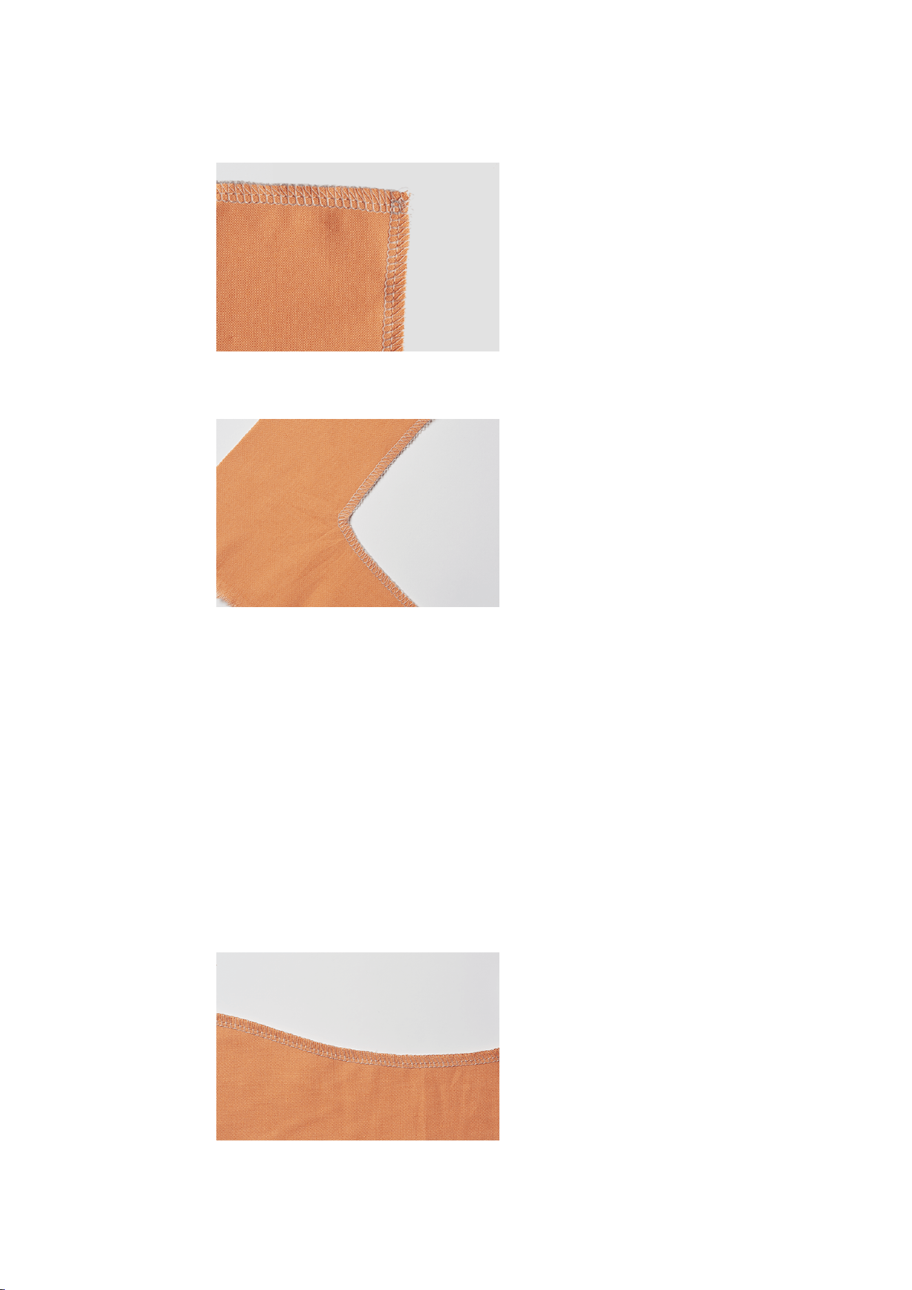
Practical Overlocking
75
2023-06 EN 5040064.10A.04
> Lower the presser foot and continue sewing.
9.6 Sewing Inner Corners
> Set the machine for a 2- or 3-thread overlock.
> Draw sewing lines on both sides of the corner about 5 cm long with the fabric pen.
> Sew the seam until the knife reaches the corner.
> Place the needle in the fabric.
> Raise the presser foot.
> Carefully pull the fabric edge to a straight line and fold the fabric forwards.
> Lower the presser foot.
> Continue sewing until the needles reach the corner.
> Place the needles exactly in the inner corner to fix the fabric.
> Raise the presser foot and fold the fabric to the back.
> Lower the presser foot and continue sewing.
9.7 Sewing Inner Curves
Inner curves appear on necklines, facings and armholes. Time-consuming clipping or trimming can be
avoided by overlocking the fabric edge.
> Set the machine for a 3- or 4-Thread Overlock.
> While sewing, stretch the curve carefully so it is straight.
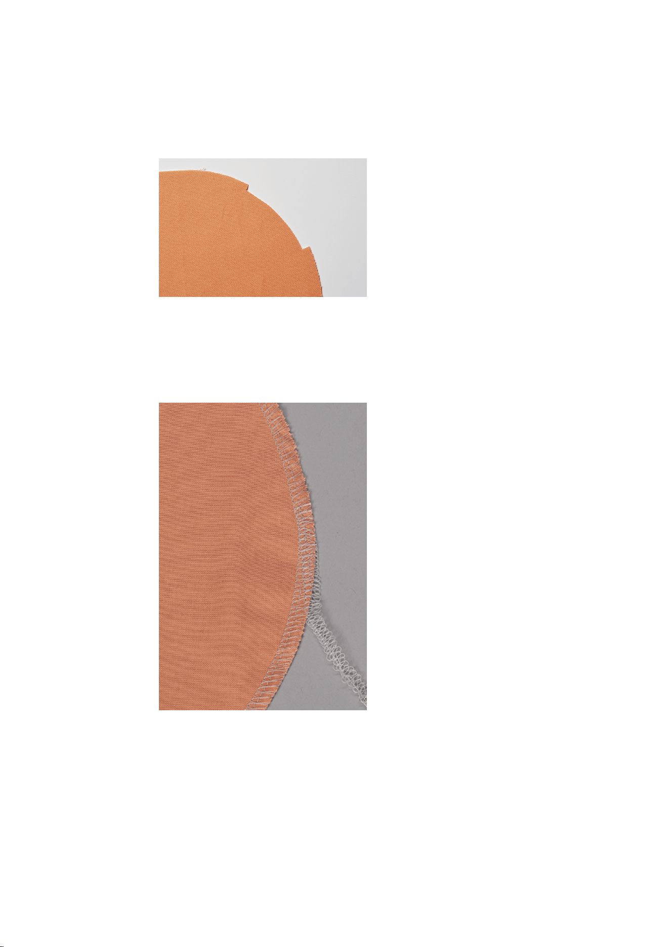
Practical Overlocking
76
2023-06 EN 5040064.10A.04
9.8 Sew Outer Curves and Circles
Due to the Differential Feed, the seam can be pulled or pushed into shape for flat, round edges.
> Cut away the seam allowance in one place along the length of the presser foot.
> Start and end the seam at the cut seam allowance.
– if seam waving out happens: set the Differential Feed to 1.5 − 2.
– if puckering happens: set the Differential Feed to 0.7 − 1.
> At the seam end, sew 1 ─ 2 stitches over the seam beginning.
> Lower the needle and raise the presser foot.
> Turn the fabric off to the left of the presser foot.
> Lower the presser foot and sew over and beyond the fabric.

Appendix
77
2023-06 EN 5040064.10A.04
10 Appendix
10.1 Storing and Transporting the Machine
Storing the Machine
The correct storage of the machine over a longer period of time has an influence on its lifespan and
functionality.
> Don't store the machine outdoors.
> Protect the machine against climatic influences.
> Before operating the machine again after storage, leave the machine unpacked for approx. 1 h at room
temperature.
Transporting the Machine
For a relocation or a longer transport of the machine, the following actions should be carried out.
> Retract the Retractable Thread Guide of the Thread Stand completely downwards.
> Lower the presser foot.
> Remove all connecting cables.
> Lift and transport the machine at the carry handle.
10.2 Maintenance and Cleaning the Machine
NOTICE
Damage by Cleaning with Compressed Air
Cleaning using aerosol sprays or compressed air may cause permanent damage to your machine. A repair
by the authorized bernette dealer is required.
> Remove fabric scraps and thread remnants using a vacuum cleaner with soft tip.
Cleaning the Machine
The service life of the machine depends on the care and maintenance. Based on normal household use, an
annual service at the Authorized bernette dealer is recommended.
Recommended aids for cleaning:
• Damp cloth
• Brush
• Tweezers
• Vacuum cleaner with soft tip
> The machine can be cleaned with a damp cloth without detergent.
> Free the sewing area from fabric and thread scraps regularly after sewing.
• Needle, Needle Bar
• Presser Foot
• Feed Dog (from above)
• Knife
• Freearm interior
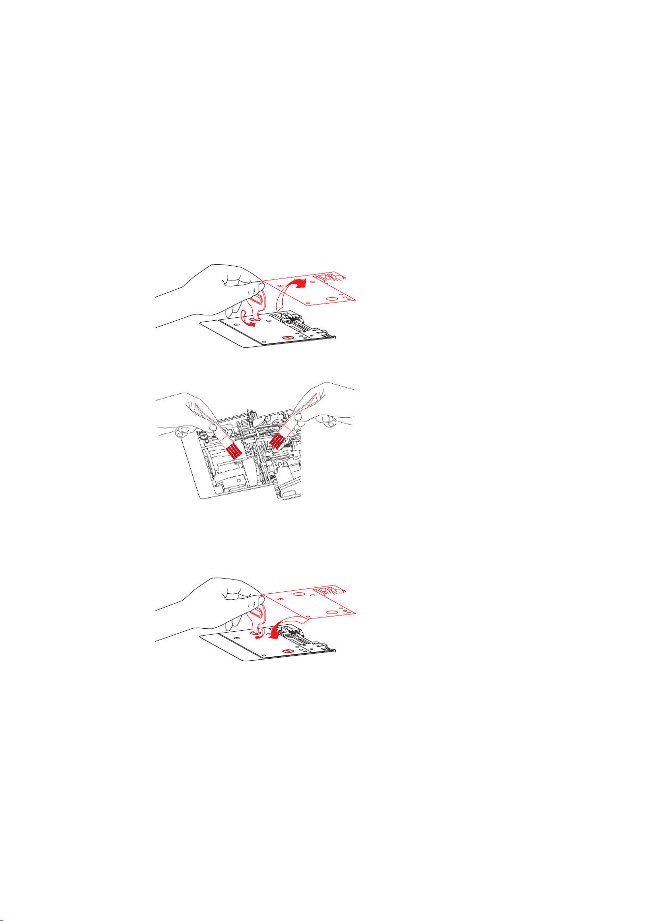
Appendix
78
2023-06 EN 5040064.10A.04
Cleaning the Looper Area
Dust, fabric and thread remnants accumulate in the looper area during overlocking and these should be
removed regularly.
Prerequisite:
• The presser foot is raised.
• The needles are in the top position.
• Switch the machine off.
> Remove the presser foot.
> Lower the knife.
> Remove the Stitch Plate from the freearm by loosening the screws.
> Remove dust, fabric and thread remnants with the brush or a vacuum cleaner.
> Attach the Stitch Plate and screw it on.
> Activate the knife.
> By slowly turning the Handwheel, ensure that the knife, the Needle and the Feed Dogs are not impeded
in their movement.
> Attach the presser foot.

Appendix
79
2023-06 EN 5040064.10A.04
Cleaning the air threader pipes
Regularly remove dust and thread remnants from the air threader pipes.
Prerequisite:
• Use a thick thread (e.g. Amann Saba C size 30) at a length of about 1 m.
> Thread the thread into the Air Threader Nozzle.
> Hold the thread at the thread ends and pull back and forth several times.
> Remove the thread at the Looper End in thread feed direction.
> Repeat the procedure for further Air Threader Nozzles with a clean thread.
Cleaning the Suction Feet
Cleaning the suction feet prevents the machine from slipping on the table at high sewing speed.
> Remove dust and thread remnants from the suction feet with a damp cloth.
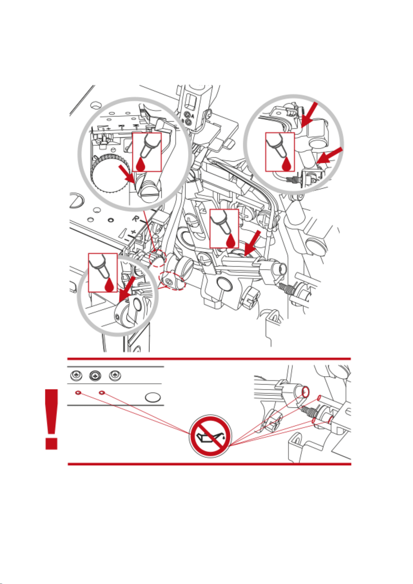
Appendix
80
2023-06 EN 5040064.10A.04
Oiling the Machine
> Regularly lubricate the upper looper joint with a drop of the supplied bernette overlock oil.

Appendix
81
2023-06 EN 5040064.10A.04
10.3 Troubleshooting
Fault Solution
Fabric does not feed well.
> Lengthen the stitch length.
> Increase the Presser Foot Pressure for heavyweight fabric.
> Decrease the Presser Foot Pressure for lightweight fabrics.
> Check the setting of the Differential Feed.
Needle breaks
> Insert the needle correctly.
> Do not pull the fabric while sewing.
> Tighten the Needle Set Screw.
> Use a larger needle on heavyweight fabrics.
Thread breakage
> Loosen the Thread Tension.
> Check the threading path.
> Check for tangled or caught thread.
> Insert the needle correctly.
> Insert a new needle; inserted needles may be bent or have a
blunt point.
> Use high quality thread.
Skipped stitches
> Insert a new needle; the inserted needles may be bent or
have a blunt point.
> Tighten the Needle Set Screw.
> Match the needle size with the fabric/thread.
> Insert the needles correctly.
> Change the type or size of the needles.
> Check the threading path.
> Increase the Presser Foot Pressure.
> Balance the Thread Tension.
> Use high quality thread.
Irregular stitches
> Balance the Thread Tension.
> Check for tangled or caught thread.
> Check the threading path.
Fabric puckers
> Check the setting of the Differential Feed.
> Loosen the Thread Tension.
> Check for tangled or caught thread.
> Use high quality thread.
> Shorten the stitch length.
> Decrease the Presser Foot Pressure for lightweight fabrics.
Irregular trimming
> Check the alignment of the Knives.
> Replace one or both Knives.
Fabric piles up
> Reduce the Presser Foot Pressure.
> Check the setting of the Differential Feed.
> Check for tangled or caught thread.
> Compress/Baste thick layers of fabric with a conventional
machine before sewing with the Overlocker.
Machine not running
> Connect machine to the power source and switch it on.
> Close the Looper cover.

Appendix
82
2023-06 EN 5040064.10A.04
10.4 Specifications
Designation Value Unit
Number of stitches 16
Number of loopers 2
Number of needles 1 ─ 2
Needle System ELx705
Needle Size 80 ─ 100 (12 ─ 16)
Differential Feed 0.6 ─ 2.0
Maximum fabric thickness 5.3 (0.23) mm (in)
Stitch Length 1.0 ─ 5.0 (0.03 ─ 0.17) mm (in)
Cutting Width Left Overlock Needle LN 5 ─ 7 (0.19 ─ 0.35) mm (in)
Cutting Width Right Overlock Needle RN 3 ─ 5 (0.11 ─ 0.27) mm (in)
Minimum sewing speed 300 Stitches per minute
Maximum sewing speed 1300 Stitches per minute
Dimensions without Retractable Thread Guide 43 x 27 x 29 (16.92/10.62/11.41) cm (in)
Dimensions with Sewing Table / Cut-offs Bin 59 x 40 x 29 (23.22/15.78/11.41) cm (in)
Weight of the machine 9.3 (20.46) kg (lb)
Weight packaged 12.8 (28.2) kg (lb)
Input voltage (energy consumption) 120 (80) / 230 ─ 240 (75) Volt (W)
Protection class (electrical engineering) II
Date of manufacture Visible on the type plate

© BERNINA International AG
Steckborn CH, www.bernina.com
www.bernette.com/b64AIRLOCK
2023-06 EN
5040064.10A.04