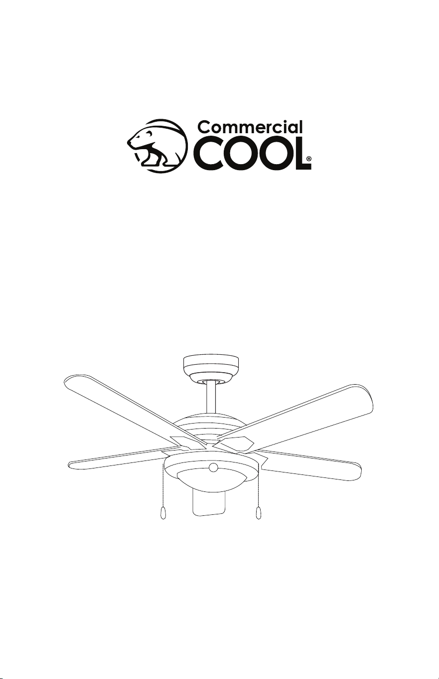
52 in. Ceiling Fan
User Manual
MODEL CCF55P60

Page 2
Thank you for purchasing our
Commercial Cool product. This
easy-to-use manual will guide you
in getting the best use of your fan.
Remember to record the model
and serial numbers. They are on a
label on the rear.
Staple your receipt to your manual.
You will need it to obtain warranty service.
Model number
Serial number
Date of purchase
PRODUCT REGISTRATION
CONTENTS
SAFETY INFORMATION
Important Safety Instructions ..........................................................................................................................................3-4
SET UP & USE
Parts .............................................................................................................................................................................................5-6
Features ......................................................................................................................................................................................... 7
Preparing for Installation ........................................................................................................................................ 8
Mounting Bracket Installation ......................................................................................................................... 9-10
Mounting Fan to Ceiling ................................................................................................................................... 11-13
Wiring Options .........................................................................................................................................................14
Securing Fan to Ceiling .......................................................................................................................................... 15
Blade Installation......................................................................................................................................................16
Light Fixture Installation ........................................................................................................................................ 17
Operation ...................................................................................................................................................................18
Cleaning + Maintenance ........................................................................................................................................19
TROUBLE SHOOTING & WARRANTY
Before You Call For Service ............................................................................................................................. 20
Customer Service ................................................................................................................................................. 20
Troubleshooting .....................................................................................................................................................21
Limited Warranty ...................................................................................................................................................................22
Page 3
SAFETY INFORMATION
IMPORTANT SAFETY INSTRUCTIONS
1. READ ALL INSTRUCTIONS BEFORE USE
2. Installation work and electrical wiring must be done by qualied
person(s) in accordance with all applicable codes and standards,
including re-rated construction.
3. Use this unit only in the manner intended by the manufacturer. If you
have any questions contact the manufacturer.
4. After making the wire connections, gently push connections into
outlet box with wire nuts pointing up. The wires should be spread
apart with the grounded conductor and the equipment grounding
conductor on one side of the outlet box and ungrounded conductor
on the other side of the outlet box.
5. Before you begin installing the fan, Switch power off at Service panel
and lock service disconnecting means to prevent power from being
switched on accidentally. When the service disconnecting means
cannot be locked, securely fasten a prominent warning device, such
as a tag, to the service panel.
6. Be cautious! Read all instructions and safety information before
installing your new fan. Review the accompanying assembly
diagrams.
7. When cutting or drilling into wall or ceiling, do not damage electrical
wiring and other hidden utilities.
8. Make sure the installation site you choose allows the fan blades to
rotate without any obstructions. Allow a minimum clearance of 7
feet (2.1 meters) from the oor to the trailing edge of the blade.
WARNING
WARNING - Hazards or unsafe
practices which COULD result in
severe personal injury or death
DANGER
DANGER - Immediate hazards
which WILL result in severe
personal injury or death
CAUTION
CAUTION - Hazards or unsafe
practices which COULD result in
minor personal injury
WARNING
TO REDUCE THE RISK OF FIRE, ELECTRIC SHOCK, OR PERSONAL INJURY, MOUNT
TO OUTLET BOX MARKED “ACCEPTABLE FOR FAN SUPPORT OF 35 LBS (15.9
KG) OR LESS” AND USE MOUNTING SCREWS PROVIDED WITH THE OUTLET
BOX AND/OR SUPPORT DIRECTLY FROM BUILDING STRUCTURE. MOST OUTLET
BOXES COMMONLY USED FOR THE SUPPORT OF LUMINARIES
ARE NOT ACCEPTABLE FOR FAN SUPPORT AND MAY NEED TO BE REPLACED.
CONSULT A QUALIFIED ELECTRICIAN IF IN DOUBT.
Page 4
SAFETY INFORMATION
9. To reduce the risk of re, electric shock, or personal injury, this fan
must be mounted to an outlet box marked suitable for fan support.
And use mounting screws provided with the outlet box. (Mounting
must support at least 35 lbs. (15.9 kg)
10. WARNING: TO REDUCE THE RISK OF PERSONAL INJURY Do not
bend blade holders during installation to motor, balancing or during
cleaning. Do not insert foreign object between rotating blades.
11. Attach the mounting bracket using only the hardware supplied with
the outlet box. Fan is only to be mounted to an outlet box marked
“Acceptable for Fan Support”.
12. Do not install within a zone measured 3 feet horizontally and 8 feet
vertically from the top of the bathtub rim or shower stall threshold.
13. Before servicing or cleaning unit, Switch power off at Service panel
and lock service disconnecting means to prevent power from being
switched on accidentally. When the service disconnecting means
cannot be locked, securely fasten a prominent warning device, such
as a tag, to the service panel.
14. All set screws must be checked and re-tightened where necessary
before installation.
15. Installation work and electrical wiring must be done by qualied
person(s) in accordance with applicable codes and standards,
including re-rated construction.
READ AND SAVE THESE
INSTRUCTIONS
HOUSEHOLD USE ONLY
WARNING
To reduce the risk of re or electric shock, do not use this fan with any solid-state
speed control device.
WARNING
To reduce the risk of personal injury, do not bend the blade brackets when installing
the brackets, balancing the blades, or cleaning the fan. Do not insert forgeign objects
in between rotating fan blades. Use only with light kits marked suitable for use in
damp locations.
Page 5
SET UP & USE
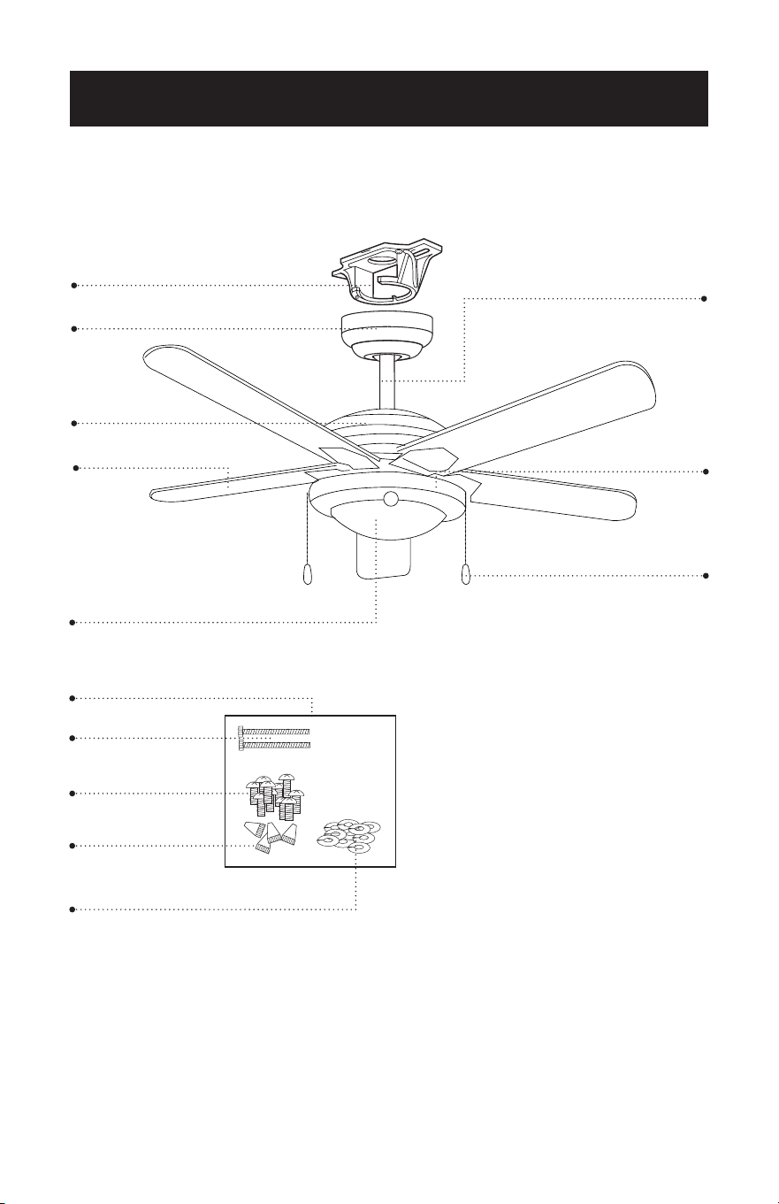
PARTS
Mounting Bracket
Blade (5)
*Light Fixture
Hardware Pack
* Bulbs not included with light xture (2) type A-19, 9W bulbs required.
Canopy
Screws
Screws for fan blade
Wire Connectors
Washers for fan blade
Motor Housing
Slide Switch
6” Downrod
Pull Chains (2)
Pull Chain Extentions (2)
Page 6
SET UP & USE
Ladder
Screwdrivers
Pliers
Wire Strippers
Electrical Tape
(optional) Power drill and drill bit
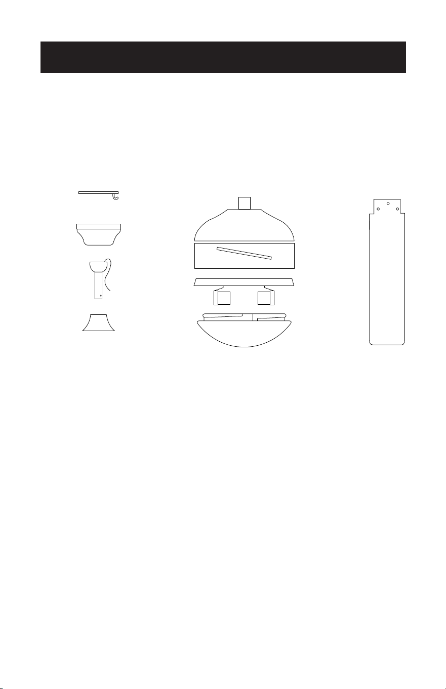
A. Mounting Bracket
B. Canopy
C. 6” Downrod assembly
D. Yoke Cover
E. Fan Motor Assembly
F. Motor Cover
G. Glass Cover (Light Fixture)
H. Fan Blades (5)
Pull Chain (2)
Pull Chain Extensions (2)
A
B E
F
G
C
D
H
RECOMMENDED TOOLS
PARTS INCLUDED
Page 7
SET UP & USE
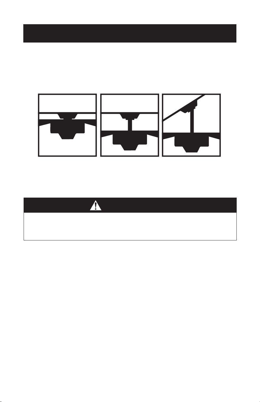
FEATURES
Downrod
Installation
For normal ceilings
Vaulted Ceiling
Installation
May require a
longer downrod
(sold separately)
CAUTION
To reduce the risk of injury to persons, the fan must be installed so that the blades
are at a height greater than 7 feet (2.1 meters) above the oor.
This fan is designed for indoor use only.
Flush
Installation
For normal ceilings
Page 8
SET UP & USE
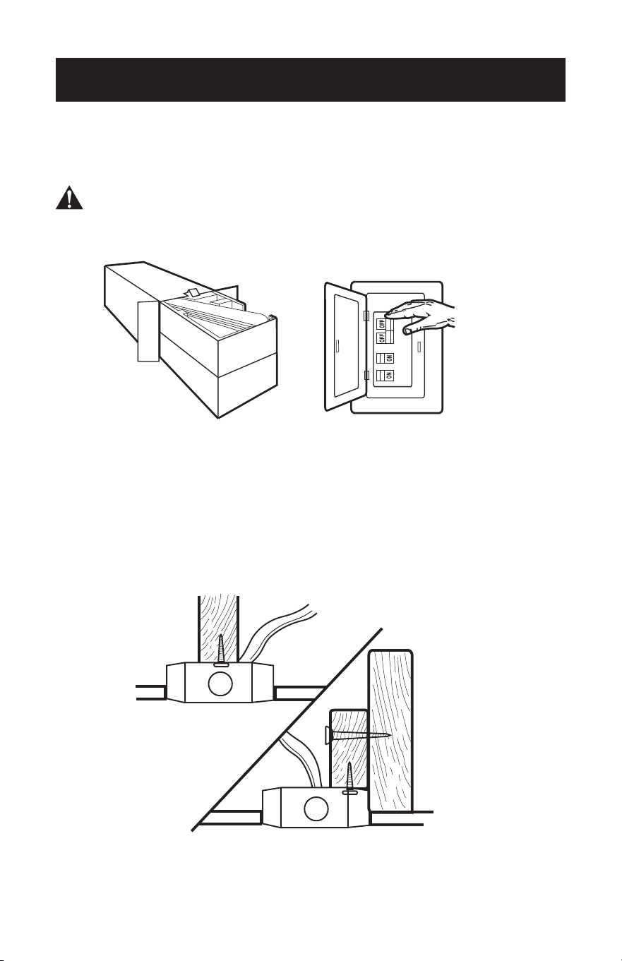
PREPARING FOR INSTALLATION
1. Unpack and inspect fan carefully to be certain all contents are included.
WARNING: Turn off power at the breaker box or fuse panel to avoid possible
electrical shock.
2. Use a listed metal outlet box suitable for fan support (rated for 35 lbs (15.9 kg)).
Before attaching fan to outlet box, ensure the outlet box is securely fastened by at
least two points to a structural ceiling member (a loose box will cause the fan to
wobble).
SET UP & USE
Page 9
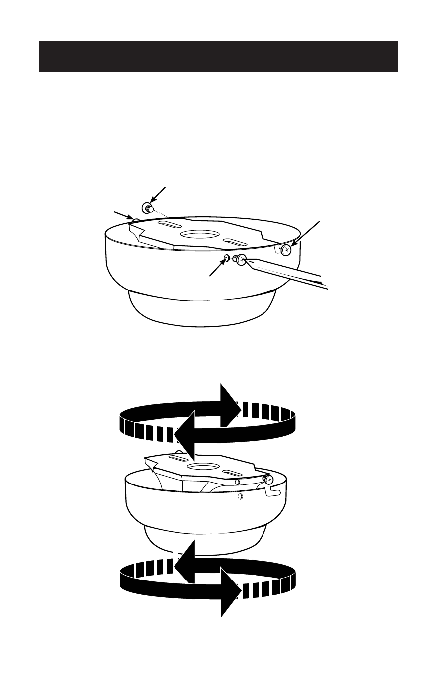
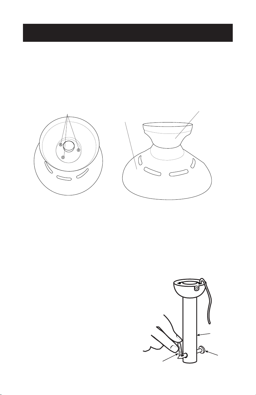
MOUNTING BRACKET INSTALLATION
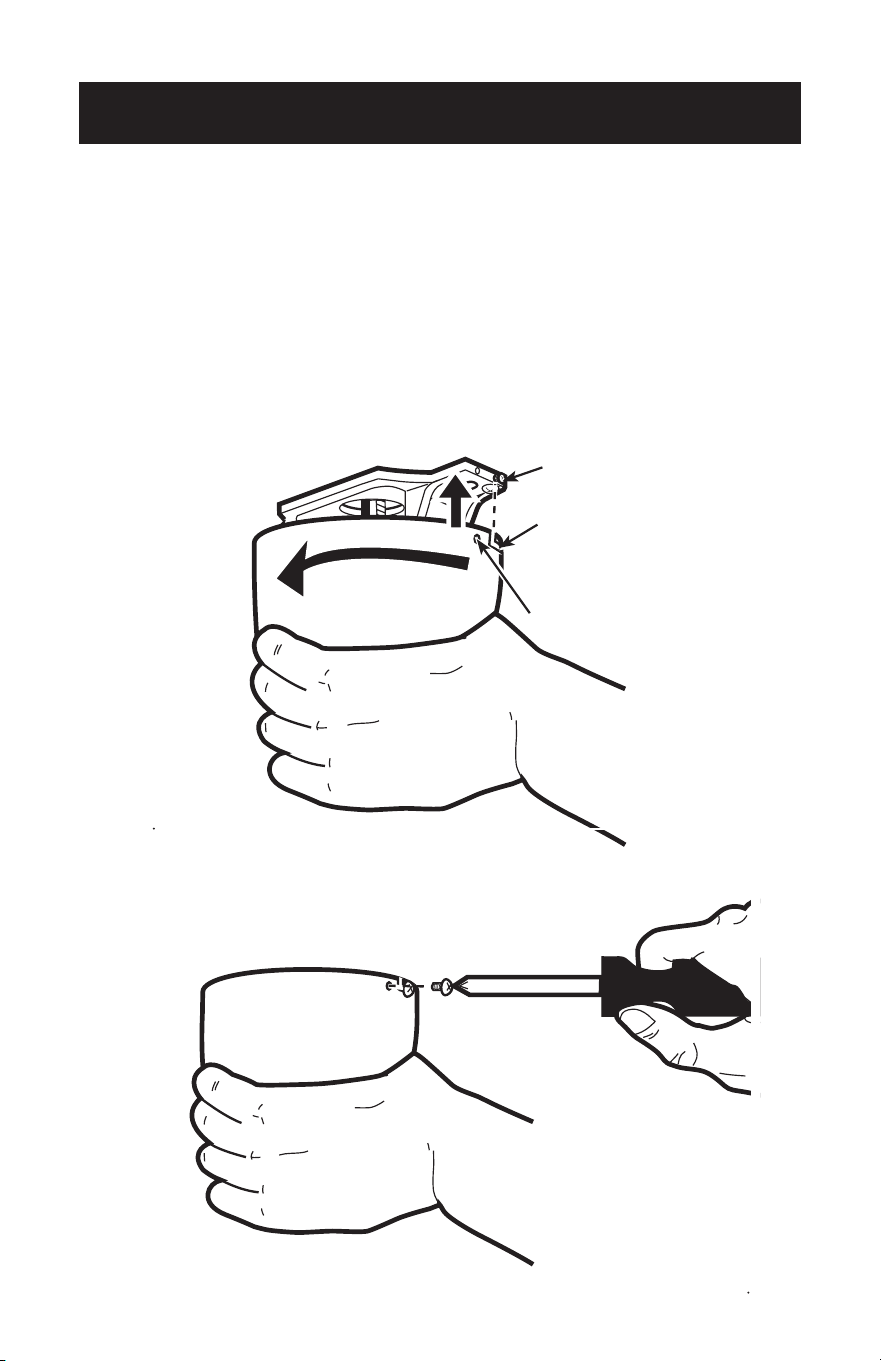
3. Remove the screws from the two mating holes (2) on the canopy. Loosen (do not
remove) the screws in the mating slots (1) on the canopy. Rotate the mounting
bracket and remove from the canopy.
2
1
1
2
2
1
1
2
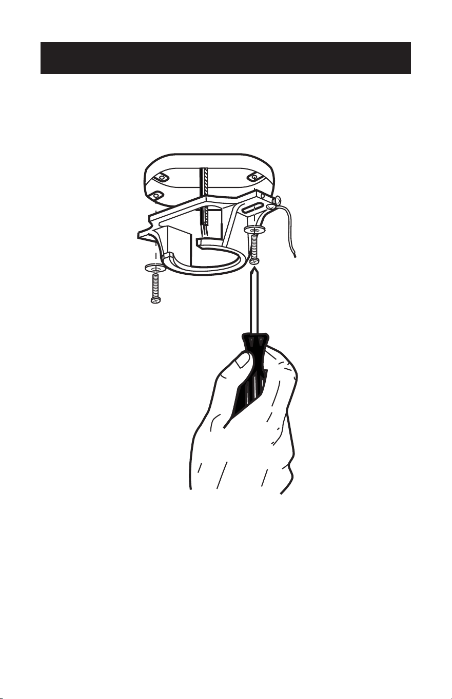
Page 10
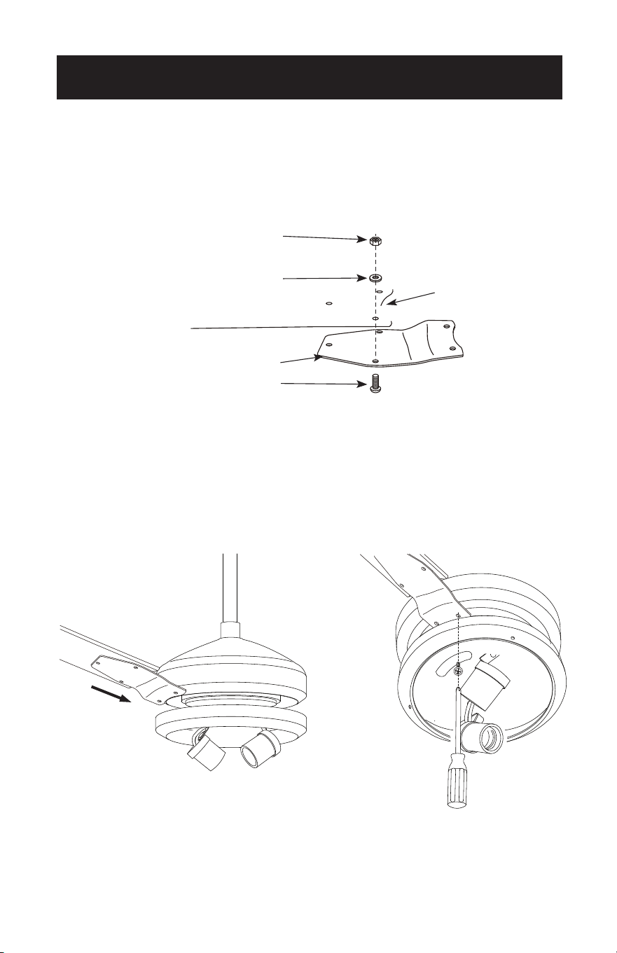
4. Install mounting bracket to outlet box in ceiling using the screws and washers
provided with the outlet box.
SET UP & USE
Page 11
SET UP & USE
5. Choose a MOUNTING OPTION (Shown on page 7):
FLUSH INSTALLATION OPTION
If installing ush, remove the screws from the canopy and reinstall 3 screws to attach
the canopy to the motor housing as shown.
Complete the wiring as shown on page 14. It will require two people to complete this
installation. Someone will need to hold the canopy and motor housing, while the wires
are being connected.
NORMAL DOWNROD OPTION
6. Remove clamp pin (1) and cross pin (2) from
downrod (3). Proceed to DOWNROD
INSTALLATION page 12, step 7.
1
2
3
Screws
Motor
Housing
Canopy
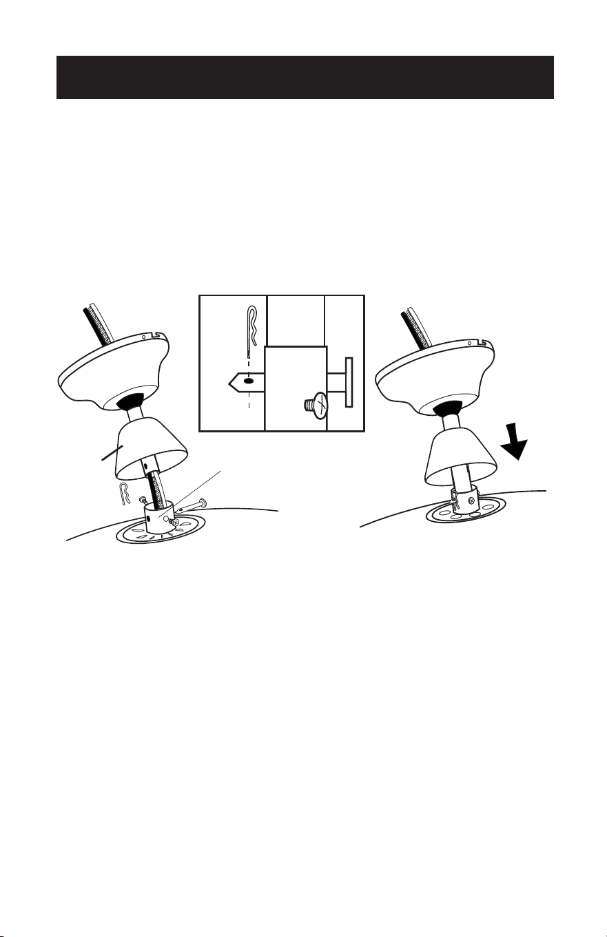
Page 12
DOWNROD INSTALLATION
7. Insert motor wires through the selected downrod and insert the downrod into
the downrod coupling. Make sure to align the hole in the downrod with the hole
in the downrod coupling. Install cross pin (1) removed in step 6 through coupling
and downrod. Insert clamp pin (2) into cross pin until it snaps into place. Tighten
set screws (3) in coupling. Slide coupling cover (4) and canopy onto the downrod
above the coupling cover.
1
4
3
2
Downrod Coupling
1
4
3
2
Downrod Coupling
SET UP & USE
Page 13
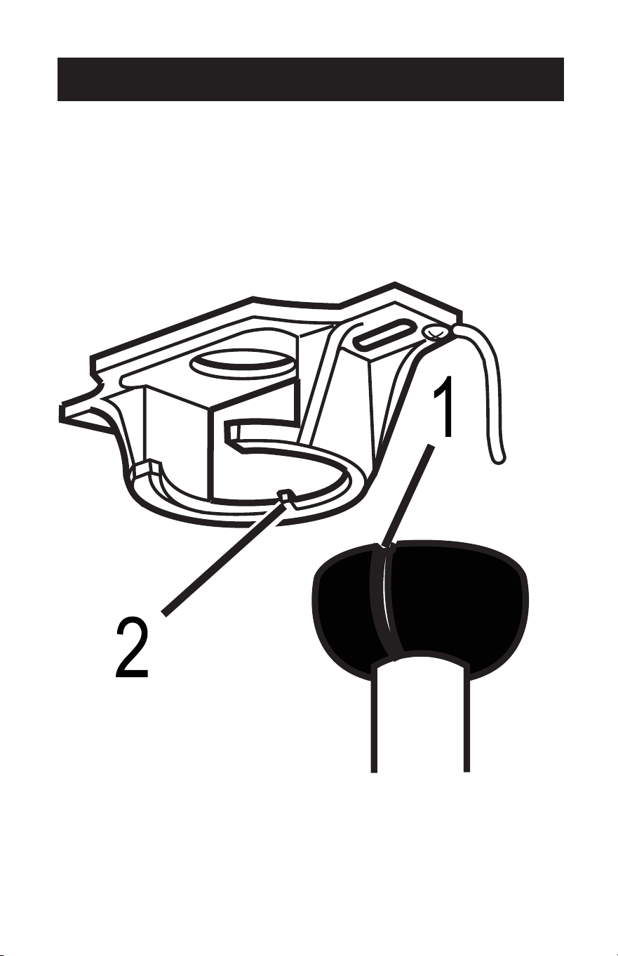
SET UP & USE
MOUNTING
8. Carefully lift fan assembly onto mounting bracket. Rotate fan until notch on
downrod ball (1) engages the ridge on the mounting bracket (2). This will allow for
hands free wiring for downrod fan installation.
NOTE: If you are installing the fan ush, you will need assistance holding the fan while
doing the wiring.
Page 14
SET UP & USE
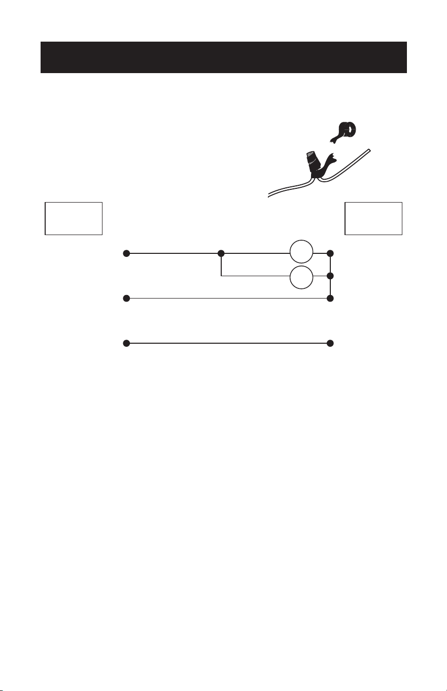
WIRING
9. In order to make sure no bare wires are exposed
after making connections it is recommended to
wrap electrical tape around each wire connector
to secure wire from being disconnected.
Use supplied wire connectors to connect the wires.
Live
Neutral
Ground
BLK BLK
BLUE
Fan
Light
GREEN
WHITE
FANCEILING
Page 15
SET UP & USE
SECURE TO CEILING
10. The canopy has two mating slots (1) and two mating holes (2). Position both slots
on canopy directly under and in line with two screws in the mounting bracket (3).
Lift the canopy, allowing the two screws to slide into the mating slots. Rotate the
canopy until both screws from the mounting bracket drop into the slot recesses.
Tighten screws securely. Install two screws into the mating holes of the canopy
and tighten to secure the canopy to the mounting bracket.
NOTE: For downrod fans, slide the canopy up to the mounting bracket.
2
3
1
2
3
1
Page 16
SET UP & USE
BLADE INSTALLATION
11. Attach the blade to the blade bracket as shown.
Insert the blade bracket to the fan motor housing. Secure each blade with the
provided screws and lock washers as shown. Slightly turn each blade after installation
and repeat the same step for each blade.
Hex Nut
Small Lock Washer
Washers
Blade Bracket
Blade Bracket Screws
Page 17
SET UP & USE
LIGHT FIXTURE INSTALLATION
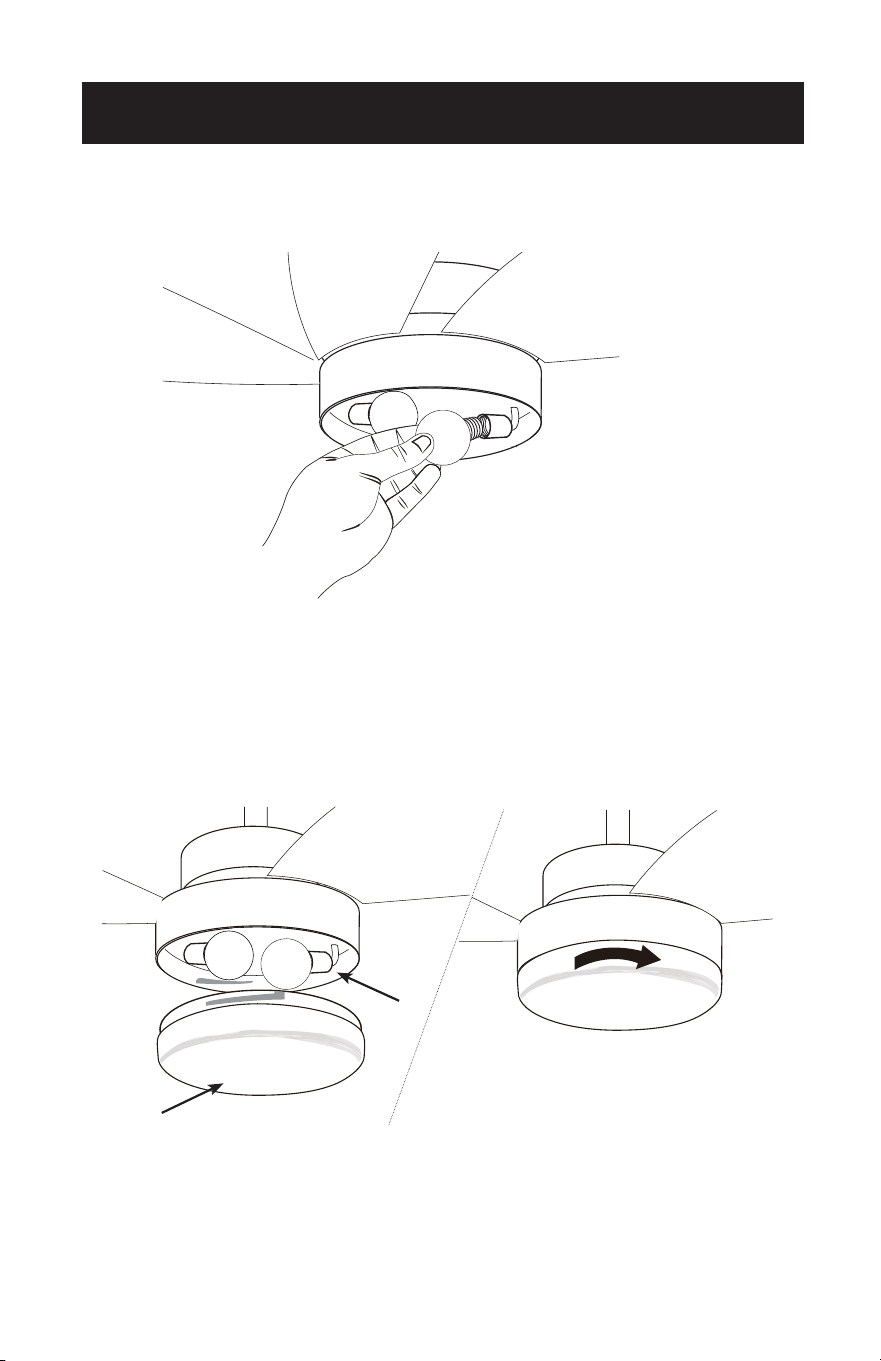
12. Install 2 light bulbs Type A-19, 9W max (not included).
13. Locate the indentations on the neck of the glass (2) and align with the protrusions
from the light kit (1). Lift the glass up allowing the protrusions to engage the
indentations on the glass, and twist the glass clockwise to lock into place.
Attach the pull chain extensions using the fobs.
1
2
1
2
SET UP & USE
OPERATION
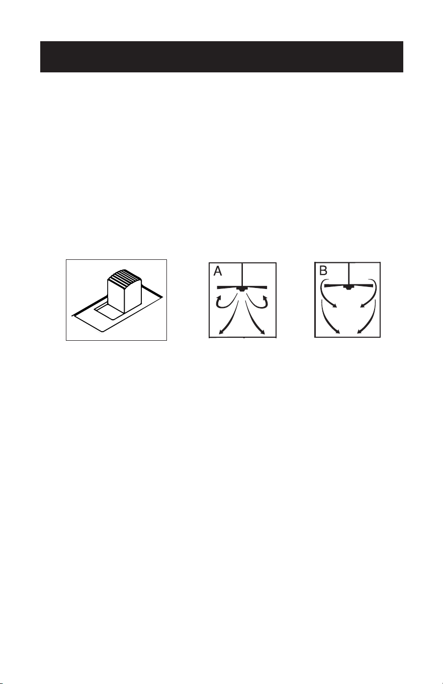
The slide switch controls direction, forward or reverse.
Warm weather - switch on left position.
Fan turns counterclockwise direction. A downward air ow creates a cooling effect as
shown in illustration A.
Cool weather - switch on right position (see image).
Fan turns clockwise direction. An upward airow moves warm air off the ceiling area
as shown in illustration B (This function will usually be used in the winter).
NOTE: Turn off and wait for fan to stop before changing the setting
of the forward/reverse slide switch.
PULL CHAIN OPERATION
One pull chain controls the light (on/off). The other pull chain is for the fan speed.
1. The rst pull will set the fan to high speed.
2. The second pull will set the fan to medium speed.
3. The third pull will set the fan to low speed.
4. The fourth pull will shut the fan off.
Page 18

Page 19
CLEANING + MAINTENANCE
1. Because of the fan’s natural movement, some connections may become loose.
Check the support connections, brackets, and blade attachments twice a year.
Make sure they are secure.
2. Clean your fan periodically to help maintain its new appearance over the years.
Do not use water when cleaning. This could damage the motor, or the wood, or
possibly cause electrical shock.
3. Use only a soft brush or lint-free cloth to avoid scratching the nish. The plating is
sealed with a lacquer coating to minimize discoloration or tarnishing.
4. There is no need to oil your fan. The motor has permanently lubricated bearings.
5. To change light bulbs, see page 17.
CLEANING + MAINTENANCE
Page 19

SET UP & USE
BEFORE YOU CALL FOR SERVICE
IF THE APPLIANCE FAILS TO OPERATE:
Check for a blown circuit fuse or a tripped main circuit breaker. If these seem to be
operating properly, test the outlet with another appliance.
IF NONE OF THE ABOVE SOLVES THE PROBLEM, CONTACT A QUALIFIED
TECHNICIAN. DO NOT TRY TO ADJUST OR REPAIR THE APPLIANCE YOURSELF.
IMPORTANT
DO NOT RETURN THIS PRODUCT TO THE STORE
If you have a problem with this product, please contact the
W Appliance Co. Customer Satisfaction Center at
844-299-0879 or [email protected].
DATED PROOF OF PURCHASE, MODEL # AND SERIAL #
REQUIRED FOR WARRANTY SERVICE
Page 20
TROUBLESHOOTING & WARRANTY
TROUBLE POSSIBLE REMEDY
If fan does not start
1. Check main and branch circuit fuses or circuit breakers.
2. Check wire connections as performed applicable installation
pages 14. CAUTION: Make sure main power is turned off.
3. Make sure forward/reverse switch is rmly in right or left
position. Fan will not operate when switch is in the middle.
4. If the fan still will not start, contact a qualied electrician. Do
not attempt to troubleshoot internal electrical connections
yourself.
If fan sounds noisy
1. Check to make sure all screws in motor housing are snug
(not over tightened).
2. Check to make sure the screws which attach the fan blade
holder to the motor are tight.
3. Allow “break-in” period of 24 hours. Most noises associated
with a new fan will disappear after this period.
If fan wobbles
1. Check that all blades are screwed rmly into blade holders.
2. Check that all blade holders are tightened securely to
motor.
3. Make sure that canopy and mounting bracket are tightened
securely to ceiling joist.
4. If blade wobble is still noticeable, interchanging two
adjacent (side by side) blades can redistribute the weight
and possibly result in smoother operation.
If light does not work
1. Check for faulty light bulbs.
2. Check to see that the wire connections in the switch
housing are connected.
3. If light kit will still not operate, contact a qualied electrician
for assistance.
Troubleshoot your problem by using the chart below. If the appliance still does not
work properly, contact W Appliance Co. customer service center. Customers must
never troubleshoot internal components.
Page 21

TROUBLESHOOTING & WARRANTY
LIMITED WARRANTY
Any repair, replacement, or warranty service,
and all questions about this product should be
directed to W Appliance Co. at 844-299-0879
from the USA or Puerto Rico.
W Appliance Co. warrants to the original purchaser
that the product will be free from defects in material,
parts and workmanship for the period designated for
this product. The warranty commences the day the
product is purchased and covers up to a period of
1 year (12 months) for labor/1 year (12 months) for
parts (manufacturing defects only).
W Appliance Co. agrees that it will, at its option,
replace the defective product with either a new
or remanufactured unit equivalent to your original
purchase during the warranty period.
Exclusions: This warranty does not apply to the
below:
1. If the appearance or exterior of
the product has been damaged or
defaced, altered or modied in design or
construction.
2. If the product original serial number
has been altered or removed or cannot
be readily determined.
3. If there is damaged due to power line
surge, user damage to the AC power
cord or connection to improper voltage
source.
4. If damage is due to general misuse,
accidents or acts of God.
5. If repair attempts are done by
unauthorized service agents, use of
parts other than genuine parts or parts
obtained from persons other than
authorized service companies.
6. On units that have been transferred
from the original owner.
7. On products that have been purchased
as refurbished, like new, second-hand, in
a “As-Is” or “Final Sale” terms.
8. To products used in a commercial or
rental setting.
9. To products used in settings other than
ordinary household use or used other
than in accordance with the provided
instructions.
10. To damages for service calls for
improper installations.
11. Transportation and shipping costs
associated with the replacement of
the unit.
12. Service calls to instruct you how to use
your product.
13. Service calls to repair or replace the
house fuse, reset the circuit breaker or
correct the wiring in the house.
REPAIR OR REPLACEMENT AS PROVIDED UNDER
THIS WARRANTY IS THE EXCLUSIVE REMEDY OF
THE CUSTOMER; W Appliance Co. SHALL NOT BE
LIABLE FOR ANY INCIDENTAL OR CONSEQUENTIAL
DAMAGES FOR BREACH OF ANY EXPRESS OR
IMPLIED WARRANTY ON THIS PRODUCT, EXCEPT
TO THE EXTENT PROHIBITED BY APPLICABLE LAW.
ANY IMPLIED WARRANTY OF MERCHANTABILITY
OF FITNESS FOR A PARTICULAR PURPOSE ON THIS
PRODUCT IS LIMITED TO THE DURATION OF THE
WARRANTY.
Some states do not allow the exclusion or limitations
of incidental or consequential damages, or limitations
on how long the warranty lasts. In these cases the
above exclusions or limitations may not apply to you.
This warranty gives you specic legal rights and you
may also have other rights which vary from state to
state.
Obtaining Service: To obtain service, product
literature, supplies or accessories please call
844-299-0879 to create a ticket for exchange/repair.
Please make sure to provide the date of purchase,
model number and a brief description of the problem.
Our customer service representative
will contact you or send detailed return instructions.
W Appliance Co. does not warrant that the appliance will work
properly in all environmental conditions, and makes no warranty
and representation, either implied or expressed, with respect
to the quality, performance, merchantability, or tness for a
particular purpose other than the purpose identied within this
user’s manual. W Appliance Co. has made every effort to ensure
that this user’s manual is accurate and disclaims liability for any
inaccuracies or omissions that may have occurred. Information
in this user’s manual is subject to change without notice and
does not represent a commitment on the part of W Appliance
Co.. W Appliance Co. reserves the right to make improvements
to this user’s manual and/or to the products described in this
user’s manual at any time without notice. If you nd information
in this manual that is incorrect, misleading, or incomplete, please
contact us at 844-299-0879.
W Appliance Co.
1356 Broadway
New York, NY 10018
Page 22


Page 24
© 2021 Commercial Cool is a W Appliance Company. All Rights Reserved.