Installation and Operation Instructions
LITHIUM STORAGE SYSTEM
BOS-G Pro
Version:V1.0

CONTENT
1.Important information in the manual.........................................................................1
1.1 Scope................................................................................................................1
1.2 Description of BOS-G Pro.................................................................................1
1.3 Meaning of Symbols........................................................................................ 2
1.4 General Safety Information..............................................................................4
1.5 Disclaimer........................................................................................................ 4
1.6 Installation environment..................................................................................5
1.7 Quality Certificate............................................................................................ 6
1.8 Requirements for Installation Personnel......................................................... 6
2. Safety..........................................................................................................................8
2.1 Safety rules.......................................................................................................8
2.2 Safety information........................................................................................... 8
3. Transport to the end customers.............................................................................. 10
3.1 Provisions on Shipping of Battery Modules...................................................10
3.2 Storage Position of the battery packaging module........................................11
4. Description and installation of BOS-G Pro battery.................................................. 13
4.1 Installation Precautions................................................................................. 13
4.2 BOS-G Pro Product Description..................................................................... 13
4.2.1 Product introduction...........................................................................13
4.2.2 Product selection................................................................................15
4.3 Technical Data................................................................................................18
4.4 Preparation.................................................................................................... 19
4.4.1 Tools required..................................................................................... 19
4.4.2 Auxiliary Tools and Materials Required.............................................. 19
4.5 Description of Rack........................................................................................ 20
4.5.1 3U-HRack Parts description................................................................ 20
4.5.2 Installation of Rack..............................................................................21
4.6 Description of Battery Module...................................................................... 22

4.7 Description of High-Voltage Control Box....................................................... 23
4.8 Description of Battery Module in Rack ..........................................................25
4.9 Wrong wiring method....................................................................................28
4.10 Installation of the Battery Module to the Rack........................................... 29
4.10.1 Cable connection.............................................................................. 31
4.10.2 Battery installation cable Description...............................................33
4.11 Battery cluster connected to inverter..........................................................35
4.12 System startup and shutdown..................................................................... 40
4.13 Procedure for configuring battery packs..................................................... 41
4.14 External 12V Power Supply of High-Voltage Control Box............................ 42
5. BOS-G Pro User Interface.........................................................................................43
5.1. Main Interface...............................................................................................43
5.2 Description of User Interface.........................................................................43
5.3 Fault viewing interface...................................................................................44
5.4 Maintenance Interface...................................................................................46
6. BOS-G Pro fault description..................................................................................... 47
7. Summary of fault types in BOS-G Pro’s screen and HVESS-Monitor....................... 50
8 Maintenance and upgrade........................................................................................52
8.1 Maintenance of BOS-G Pro............................................................................52
8.2 USB’s Upgrade Step........................................................................................53
9. Battery Module Storage...........................................................................................54
10. Disposal..................................................................................................................55
11. Legal notice............................................................................................................56

1
1.Important information in the manual
1.1 Scope
The installation and operation manual applies to the modular battery energy storage system.
Please carefully read this installation and operation manual to ensure the safe installation,
preliminary debugging, and maintenance of BOS-G Pro. Installation, preliminary debugging, and
maintenance must be carried out by qualified and authorized personnel. Please keep this
installation and operation manual and other applicable documents near the battery energy
storage system, so that all personnel involved in installation or maintenance can access this
installation and operation manual at any time.
This installation and operation manual only applies to countries meeting the certification
requirements. Please observe the applicable local laws, regulations, and standards. Standards
and legal Provisions of other countries may be inconsistent with the Provisions and specifications
in this manual. In this case, please contact our after-sales service personnel, hotline: +86 0574
8612 0560, email: service-ess@deye.com.cn.
1.2 Description of BOS-G Pro
Model
System
energy
(kWh)
Rated
DC
power
(kW)
Discharge
depth
Composition
BOS-G25-Pro
25.6
25.6
90%
BOS-G-PACK5.1*5+BOS-G Pro-2 1000V/100A*1
BOS-G30-Pro
30.72
30.72
90%
BOS-G-PACK5.1*6+BOS-G Pro-2 1000V/100A*1
BOS-G35-Pro
35.84
35.84
90%
BOS-G-PACK5.1*7+BOS-G Pro-2 1000V/100A*1
BOS-G40-Pro
40.96
40.96
90%
BOS-G-PACK5.1*8+BOS-G Pro-2 1000V/100A*1
BOS-G45-Pro
46.08
46.08
90%
BOS-G-PACK5.1*9+BOS-G Pro-2 1000V/100A*1
BOS-G50-Pro
51.2
51.2
90%
BOS-G-PACK5.1*10+BOS-G Pro-2 1000V/100A*1
BOS-G55-Pro
56.32
56.32
90%
BOS-G-PACK5.1*11+BOS-G Pro-2 1000V/100A*1
BOS-G60-Pro
61.44
61.44
90%
BOS-G-PACK5.1*12+BOS-G Pro-2 1000V/100A*1
BOS-G65-Pro
66.56
66.56
90%
BOS-G-PACK5.1*13+BOS-G Pro-2 1000V/100A*1
BOS-G70-Pro
71.68
71.68
90%
BOS-G-PACK5.1*14+BOS-G Pro-2 1000V/100A*1
BOS-G75-Pro
76.8
76.8
90%
BOS-G-PACK5.1*15+BOS-G Pro-2 1000V/100A*1
BOS-G80-Pro
81.92
81.92
90%
BOS-G-PACK5.1*16+BOS-G Pro-2 1000V/100A*1
BOS-G85-Pro
87.04
87.04
90%
BOS-G-PACK5.1*17+BOS-G Pro-2 1000V/100A*1
2
1.3 Meaning of Symbols
This manual contains the following types of warnings:
Danger! It may cause an electric shock.
Even when the equipment is disconnected from the power grid, the voltage-free
state will have a time lag.
Danger! If the instructions are not observed, death or severe injury may
occur.
Warning! If the instructions are not observed, a loss may occur.
Attention! This symbol represents information on the device use.
Symbols on equipment:
The following types of warning, Prohibition, and mandatory symbols are also used on
the equipment.
Attention! The risk of chemical burns
If the battery is damaged or fails, it may lead to electrolyte leakage, which in turn causes the
formation of a small amount of hydrofluoric acid, among other effects. Contact with these liquids
can cause chemical burns.
• Do not subject the battery module to severe impact.
• Do not open, disassemble or mechanically change the battery module.
• In case of contact with an electrolyte, wash the affected area with clean water immediately and
seek medical advice Promptly.
Attention! The risk of explosion
Incorrect operation or fire may cause the lithium-ion battery unit to ignite or explode, leading to
serious injury.
• Do not install or operate the battery module in explosive or high-humidity areas.
3
• Store the battery module in a dry place within the temperature range specified in the data
sheet.
• Do not open, drill through or drop the battery cell or module.
• Do not expose the battery cell or module to high temperatures.
• Do not throw the battery cell or module into the fire.
• When the lithium battery catches fire after being plugged in with AC power, unplug the power
supply first to prevent electric shock during fire fighting.
• If there is an open flame, use carbon dioxide or ABC dry powder fire extinguisher to put out the
fire, and then cool down by using the nearby fire hydrant or pouring water until no white smoke
appears and the battery is completely cooled down. After extinguishing the fire, continue to
monitor the battery for at least 1 hour to prevent re-ignition.
• If there is no open flame but a large amount of white smoke comes out of the battery, it is
recommended to use a 6L portable water-based fire extinguisher (if any), and then cool down by
using the nearby fire hydrant or pouring water until no white smoke appears and the battery is
completely cooled down. After extinguishing the fire, continue to monitor the battery for at least
1 hour to prevent re-ignition.
• Do not use defective or damaged battery modules.
Caution! Hot surface
• If a malfunction occurs, the parts will become very hot, and touching them may cause serious
injury.
• If the energy storage system is defective, please shut it down immediately.
• If the fault or defect becomes obvious, special care should be taken when handling the
equipment.
No open fire! It is Prohibited to handle open flames and ignition sources near the
energy storage system.
Do not insert any objects into the opening in the housing of the energy storage system!

4
No objects, such as screwdrivers, may be inserted through openings in the casing of the storage
system.
Wear safety goggles! Wear safety goggles when working on the equipment.
Follow the manual! When working and operating the equipment, the installation and
operation manual Provisions must be observed.
1.4 General Safety Information
Danger! Failure to comply with the safety information can lead to life-threatening
situations.
1. ImProper use can cause death. Operators of BOS-G Pro must read this manual and observe all
safety information.
2. Operators of BOS-G Pro must comply with the specifications in this manual.
3. This manual cannot describe all conceivable situations. For this reason, applicable standards
and relevant occupational health and safety regulations are always given priority.
4. In addition, the installation may involve residual hazards in the following circumstances:
• Incorrect installation.
• The installation is carried out by personnel who did not receive relevant training or guidance.
• Failure to observe the warnings and safety information in this manual.
If there are any questions, please contact Deye after service.
1.5 Disclaimer
DEYE ESS TECHNOLOGY CO., LTD shall not be liable for personal injury, Property loss, Product
damage and subsequent losses under the following circumstances.
• Failure to comply with the Provisions of this manual.
• Incorrect use of this Product.

5
• Unauthorized or unqualified personnel repair the Product, disassembly the rack and perform
other operations.
• Use of unapProved spare parts.
• Unauthorized modifications or technical changes to the Product.
1.6 Installation environment
• The battery energy storage system can only be installed and operated in an enclosed space. The
working environment temperature range of BOS-G Pro is -20 ℃ ~ 55 ℃ , and the maximum
humidity is 85%. The battery module shall not be exposed to the sun or placed directly beside the
heat source.
• The battery module shall not be exposed to a corrosive environment.
• When installing the battery energy storage system, ensure that it stands on a sufficiently dry
and flat surface with sufficient bearing capacity. Without the manufacturer’s written apProval,
the installation site’s altitude shall not be higher than 3,000 meters. The output power of the
battery decreases with the altitude.
• In areas where flooding may occur, care must be taken to ensure that the battery module is
installed at a suitable height and to prevent its contact with water.
• The battery energy storage system must be installed in a fireProof room. This room must have
no fire source and must be equipped with an independent fire alarm device, which complies with
local applicable regulations and standards. According to local applicable regulations and
standards, the room must be separated by the T60 fire door. Similar fire-Proof requirements
apply to other openings in the room (such as windows).
Compliance with the specifications in this manual is also part of Proper use.
The use of the BOS-G Pro system is Prohibited in the following circumstances:
• Mobile use on land or in the air (use on water only with the manufacturer's consent and with
the manufacturer's written consent).
• Used in medical devices.
• Used as a UPS system.
6
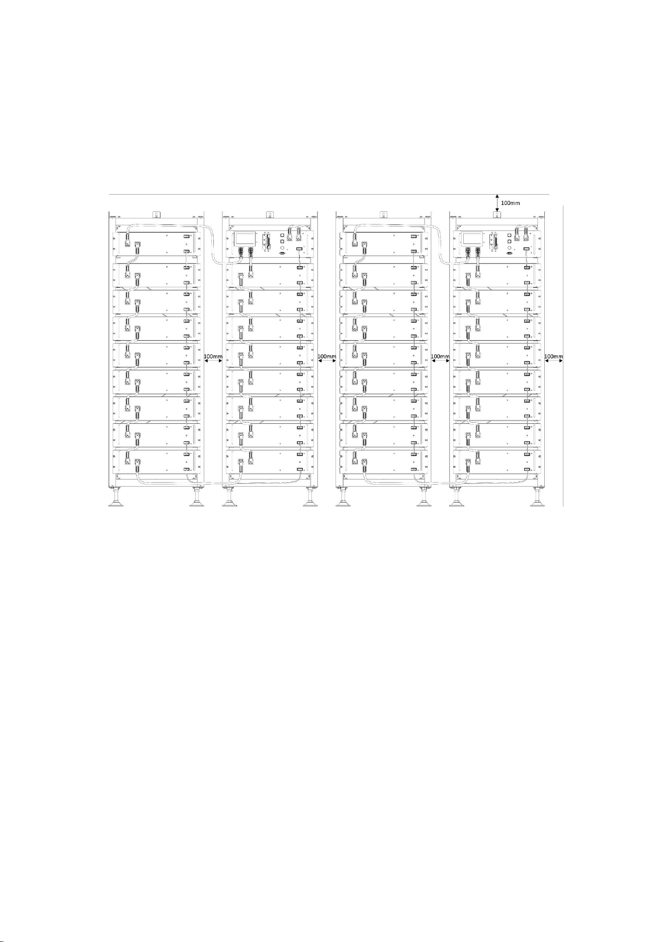
Minimum Product installation distance
The minimum distance to the surrounding building when the battery is installed is
100mm, and the minimum distance between the two Products is 100mm.
1.7 Quality Certificate
The quality certificate can be downloaded from www.deyeess.com.
1.8 Requirements for Installation Personnel
All work shall comply with local applicable regulations and standards.
The installation of BOS-G Pro can only be completed by electricians with the following
qualifications:
• Trained in dealing with hazards and risks associated with the installation and operation of
electrical equipment, systems, and batteries.
• Trained on installation and debugging of electrical equipment.

7
• Understanding and complying with the technical connection conditions, standards, guidelines,
regulations, and laws applicable.
• Knowledge of handling lithium-ion batteries (transportation, storage, disposal, hazard source).
• Understanding and complying with this document and other applicable documents.

8
2. Safety
2.1 Safety rules
To avoid Property damage and personal injury, the following rules shall be followed when
working on the hazardous live parts of the battery energy storage system:
• It is available for use.
• Ensure that it will not restart.
• Make sure there is no voltage.
• Grounding Protection and short circuit Protection
• Cover or shield adjacent live parts.
2.2 Safety information
Part damage or short circuit may cause electric shock and death. A short circuit can be caused by
connecting battery terminals, resulting in current flow. This type of short circuit shall be avoided
under any circumstances. For this reason, follow these instructions:
• Use insulated tools and gloves.
• Do not put any tools or metal parts on the battery module or high-voltage control box.
• When operating the battery, be sure to remove watches, rings, and other metal objects.
• Do not install or operate this system in explosive or high-humidity areas.
• When working on the energy storage system, first turn off the charging controller, then the
battery, and ensure that they are not turned on again.
ImProper use of the battery energy storage system can lead to death. The use of the battery
energy storage system beyond its intended use is not allowed, because it may cause great danger.
ImProper handling of the battery energy storage system can cause life-threatening risks, serious
injury or even death.

9
Warning! ImProper use can cause damage to the battery cell.
• Do not expose the battery module to rain or soak it in liquid.
• Do not expose the battery module to a corrosive environment (such as ammonia and salt).
• The battery energy storage system shall be debugged no later than six months after delivery.
10
3. Transport to the end customers
3.1 Provisions on Shipping of Battery Modules
It is necessary to comply with the relevant regulations and Provisions on roads for shipping
lithium-ion Products in the corresponding countries.
It is Prohibited to smoke in the vehicle during transportation or in the vicinity during
loading and unloading.
The dangerous goods transport vehicles shall meet relevant regulations concerning road
transportation and shall be equipped with two tested CO2 fire extinguishers.
It is forbidden for the freight forwarder to open the outer package of the battery module.
Use only apProved lifting equipment to move the battery cabinet system. Use only the hanging
lug on the top of the battery cabinet as the connection point. When lifting, the angle of the sling
must be at least 60°.
ImProper vehicle transportation can cause injury. ImProper transportation or imProper
transportation locks may cause the load to slip or overturn, resulting in injury. The cabinet shall
be placed vertically to prevent it from sliding in the vehicle, and a fixing belt shall be used.
A tilting of the battery rack may cause injury. The maximum weight of a single battery
rack of BOS-G Pro can reach 622 kg. When tilted, they may overturn, causing injury and damage.
Ensure that the battery cabinet is on a stable surface and that it does not tilt due to load or force.
The battery energy storage system can be damaged, if not Properly transported. The
battery module can only be transported vertically. Note that these parts may be top-heavy.
Failure to follow this instruction may result in damage to the part.
During transportation, the battery storage rack may be damaged when it is installed with
the battery module. The battery storage rack is not designed to be transported with the installed
battery modules. Always transport the battery module and the battery rack separately. Once the
battery module is installed, do not move the battery rack, and do not lift it by a lifting device.
11
If possible, do not remove the transport packaging before arrival at the installation site.
Before removing the transport Protector, check if the transport packaging is damaged, and check
the impact indicator on the outer packaging of the battery converter. If the impact indicator is
triggered, the possibility of transport damage cannot be ruled out.
ImProper transportation of battery modules may cause injury. The single battery module
weighs 46 kg. If it falls or slips, it may cause injury. Only use suitable transport and lifting
equipment to ensure safe transport.
Wear safety shoes to avoid the danger of injury. When transporting the battery rack and
battery module, their parts may be crushed due to their heavy weight. Therefore, all persons
involved in transportation must wear safety shoes with toe caps. Please observe the safety
regulations for transportation at the end customer's site, especially during loading and unloading.
During transportation and installation of unpacked battery storage cabinets, the risk of
injury increases, especially on sharp metal panels. Therefore, all personnel involved in
transportation and installation must wear Protective gloves.
The maximum weight of a single rack of BOS-G Pro can reach 622kg. We suggest that at
least 2-3 people work together to install the battery rack. The lifting device is helpful for heavy
parts, and the pulley or cart for light parts. Be careful not to damage the case. The number of
battery modules stacked shall not be more than 8.
Check whether the delivery is complete.
3.2 Storage Position of the battery packaging module
The battery module can only be transported in an upright position. Please note that the battery
rack may be very top-heavy.

12

13
4. Description and installation of BOS-G Pro battery
4.1 Installation Precautions
WARNING! Possible damage to the building due to static overload
1. The total weight of the battery storage system is 883 kg. Ensure that the installation site has
sufficient bearing capacity.
2. When selecting the installation site, consider the transportation route and necessary site
cleanup.
3. Installation levelness: The allowable deviation is less than 5mm.
4.2 BOS-G Pro Product Description
4.2.1 Product introduction
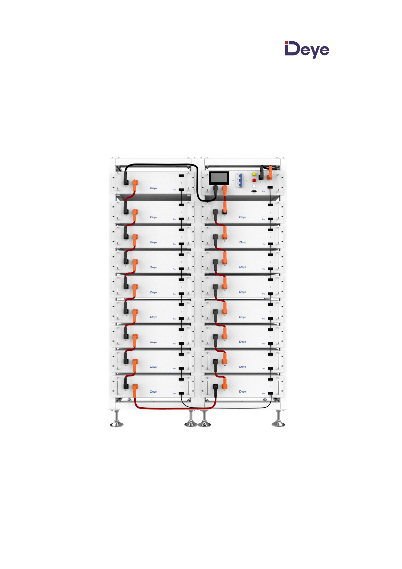
BOS-G Pro is a high-voltage lithium-ion battery system. It Provides a reliable backup power supply
for supermarkets, banks, schools, farms and small factories to smooth the load curve and achieve
peak load transfer. It can also imProve the stability of renewable systems and Promote the
application of renewable energy.
It is characterized by high integration, good reliability, long service life, wide working temperature
range, etc. The battery energy storage system is modular. Each battery module has a capacity of
5.12 kWh. It can support up to 17 battery modules in series. Its total energy can be expanded
from 25.6 kWh to 87.04 kWh.
14
15
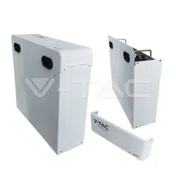
4.2.2 Product selection
We offer our customers three options:
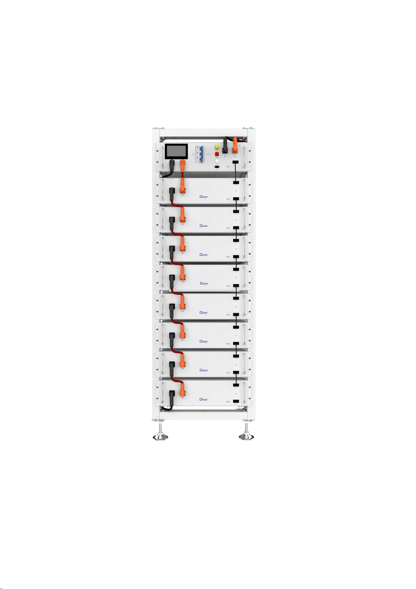
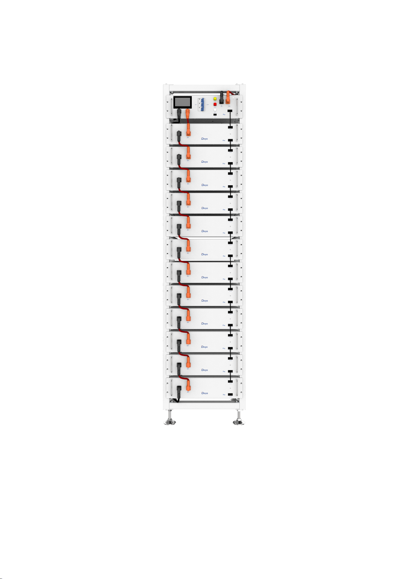
The first option: requires 5 to 8 battery modules can choose a 9-layer Product
solution. The Product appearance is shown in the following figure:
16
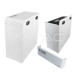
The second option: need 9~12 battery modules can choose 13-layer Product solution.
The Product appearance is shown in the following figure:
17
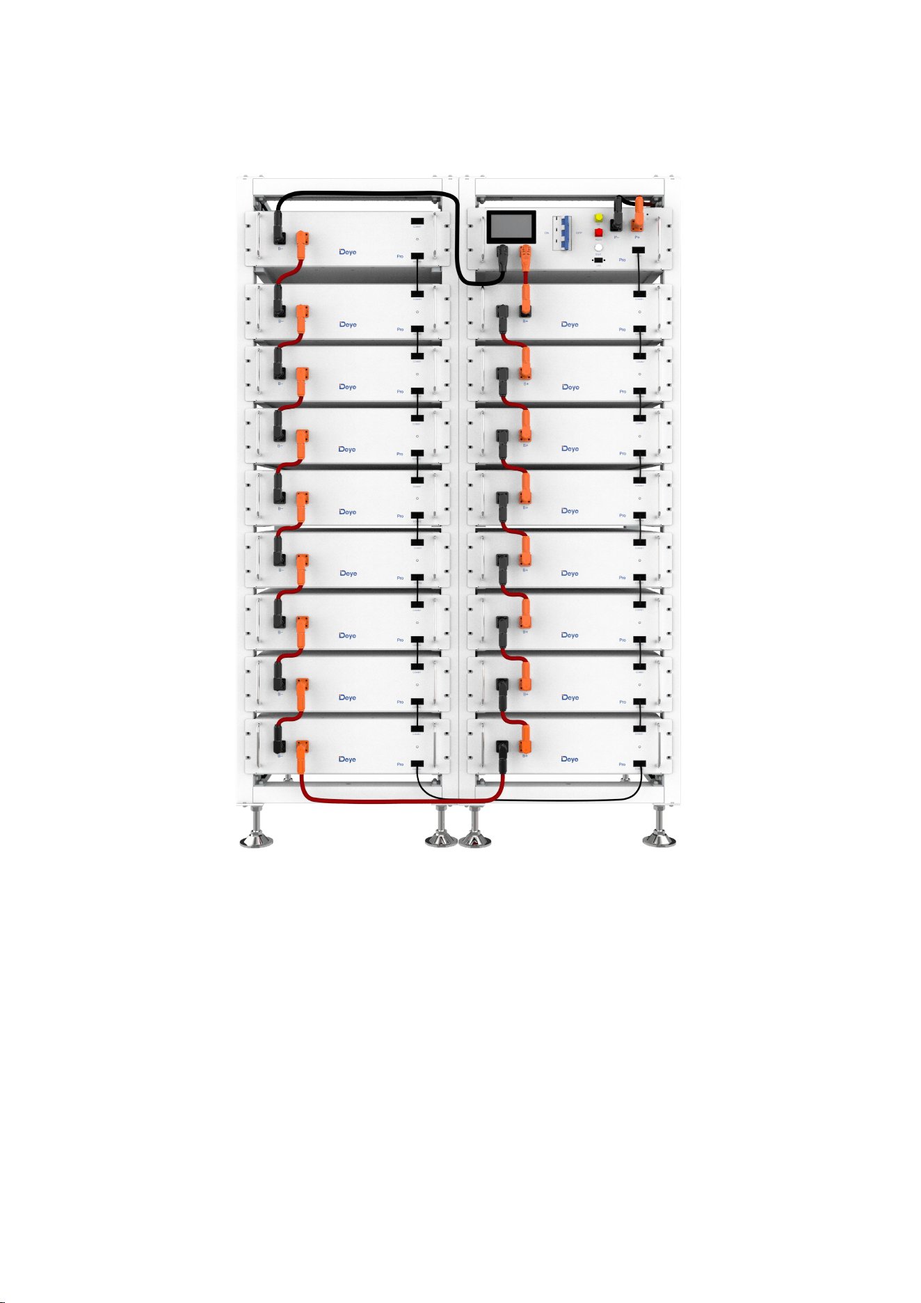
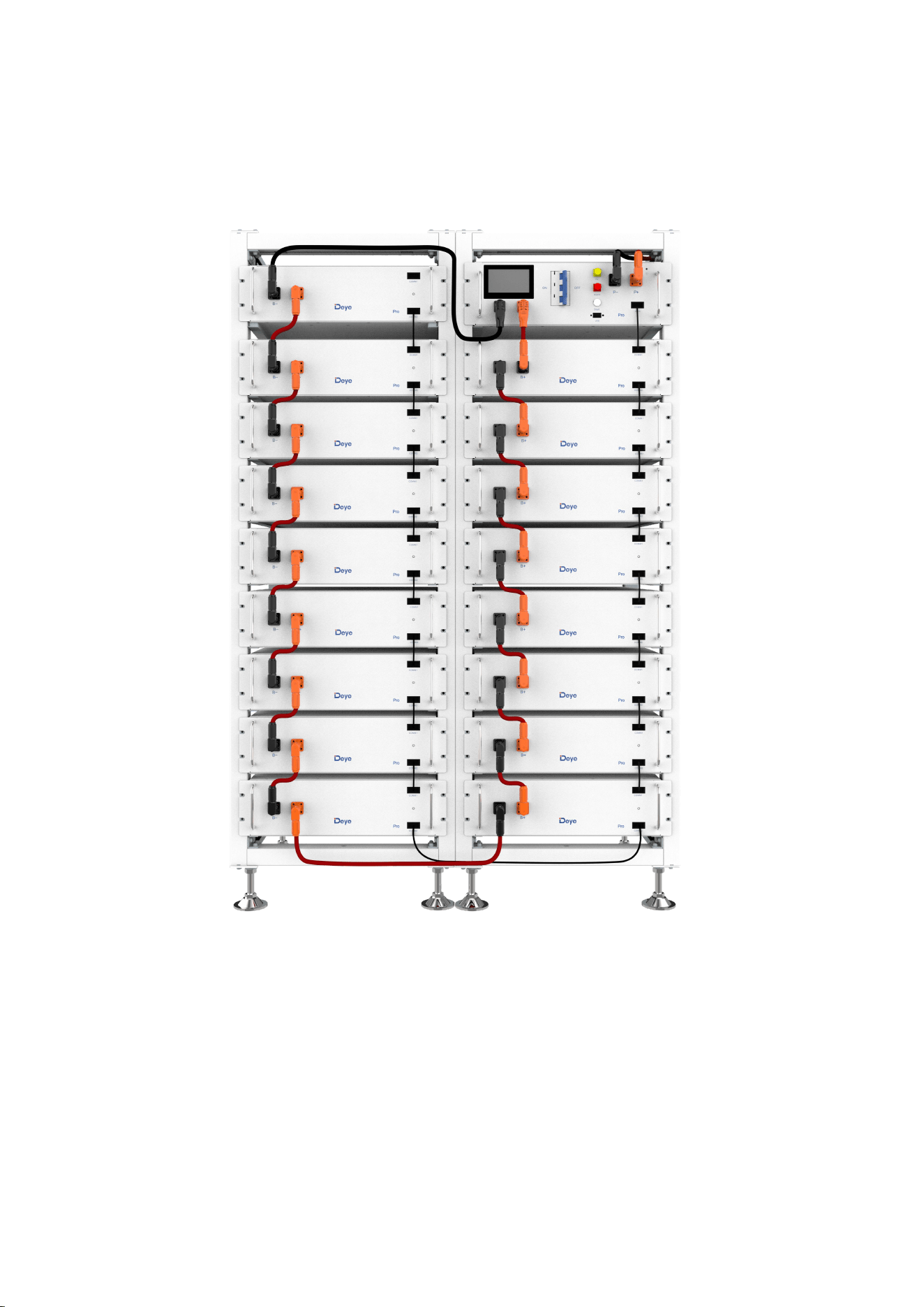
The third option: need 13~17 battery modules can choose two 9-layer Product
solution. The Product appearance is shown in the following figure:

18
4.3 Technical Data
The energy of the battery system
(5~17 battery modules)
5 battery modules
25.6kWh
6 battery modules
30.72kWh
7 battery modules
35.84kWh
8 battery modules
40.96kWh
9 battery modules
46.08kWh
10 battery modules
51.2kWh
11 battery modules
56.32kWh
12 battery modules
61.44kWh
13 battery modules
66.56kWh
14 battery modules
71.68kWh
15 battery modules
76.8kWh
16 battery modules
81.92kWh
17 battery modules
87.04kWh
Charge-discharge rate (Max)
1C
Battery cell chemistry
LiFePO
4
Maximum charging/discharging current
100A
Module capacity
100Ah
Working voltage
8 battery modules
332.8~467.2V
12 battery modules
499.2~700.8V
17 battery modules
707.2~992.8V
Working temperature
Charge: 0~55℃/Discharge:-20~55℃
Humidity
5% - 85% (RH)
The altitude of the installation site
≤ 3000 m
Dimensions (W x D x H)
9-layer: 530*602*1629mm
13-layer: 530*602*2219mm
Two 9-layer: 1060*602*1629mm
Warranty period
10 years
The total weight (8 battery modules, 1 rack)
428 kg
The total weight (12 battery modules, 1 rack)
622 kg
The total weight (17 battery modules, 2 rack)
883 kg
Weight of each battery module/9 battery rack
/13 battery rack
46 kg | 41 kg| 51 kg
Case Protection grade
IP20
Certification
UN38.3/CE/CE-EMC/
IEC62040/CEC/VDE/CEI

19
4.4 Preparation
4.4.1 Tools required
TOOL
USE
L-shaped hexagonal wrench
• Fixed beam with left and right welding frame
• Fixed beam with diagonal support
10mm hexagon socket
• Fix the expansion screw
24mm wrench
• Adjust the height of the base and tighten the nut.
4.4.2 Auxiliary Tools and Materials Required
AID/MATERIAL
Auxiliary tools/materials
USE
Fastening materials (M6*20 screws, M6*100
expansion screws, M6 nuts)
1. Assemble the battery racks and fix them
on the wall or connect the two racks.
2. Assemble the battery modules and high-
voltage control boxes, and fix them to the
racks.
20
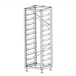
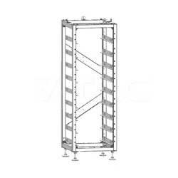
4.5 Description of Rack
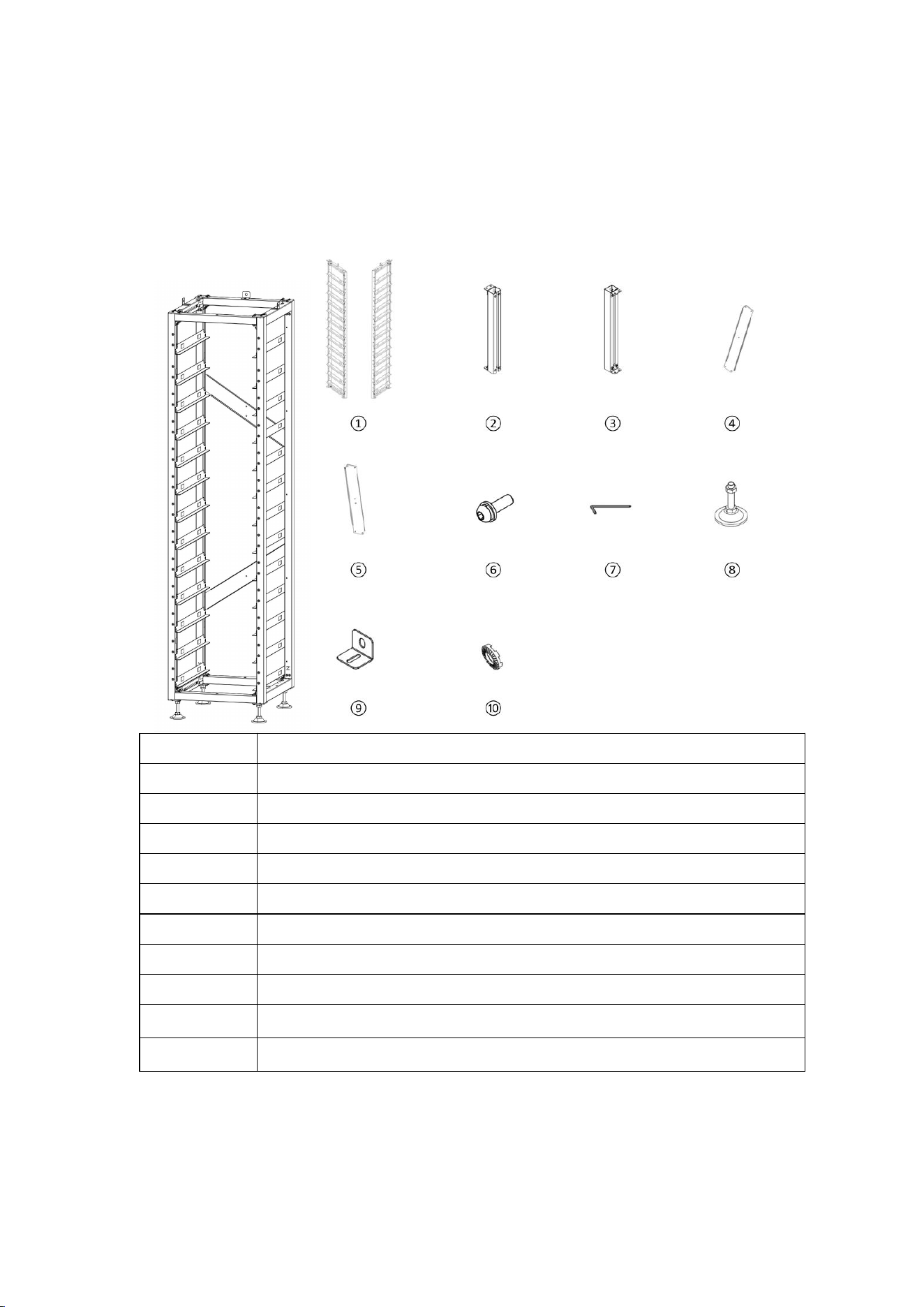
4.5.1
3U-HRack Parts description
No.
Description
①
Side beam
②
Top beam
③
Bottom beam
④
Left diagonal brace
⑤
Right diagonal brace
⑥
Round head hexagon socket combination screws
⑦
Allen wrench
⑧
Base
⑨
Rack fastener
⑩
Broken lacquer flakes
21
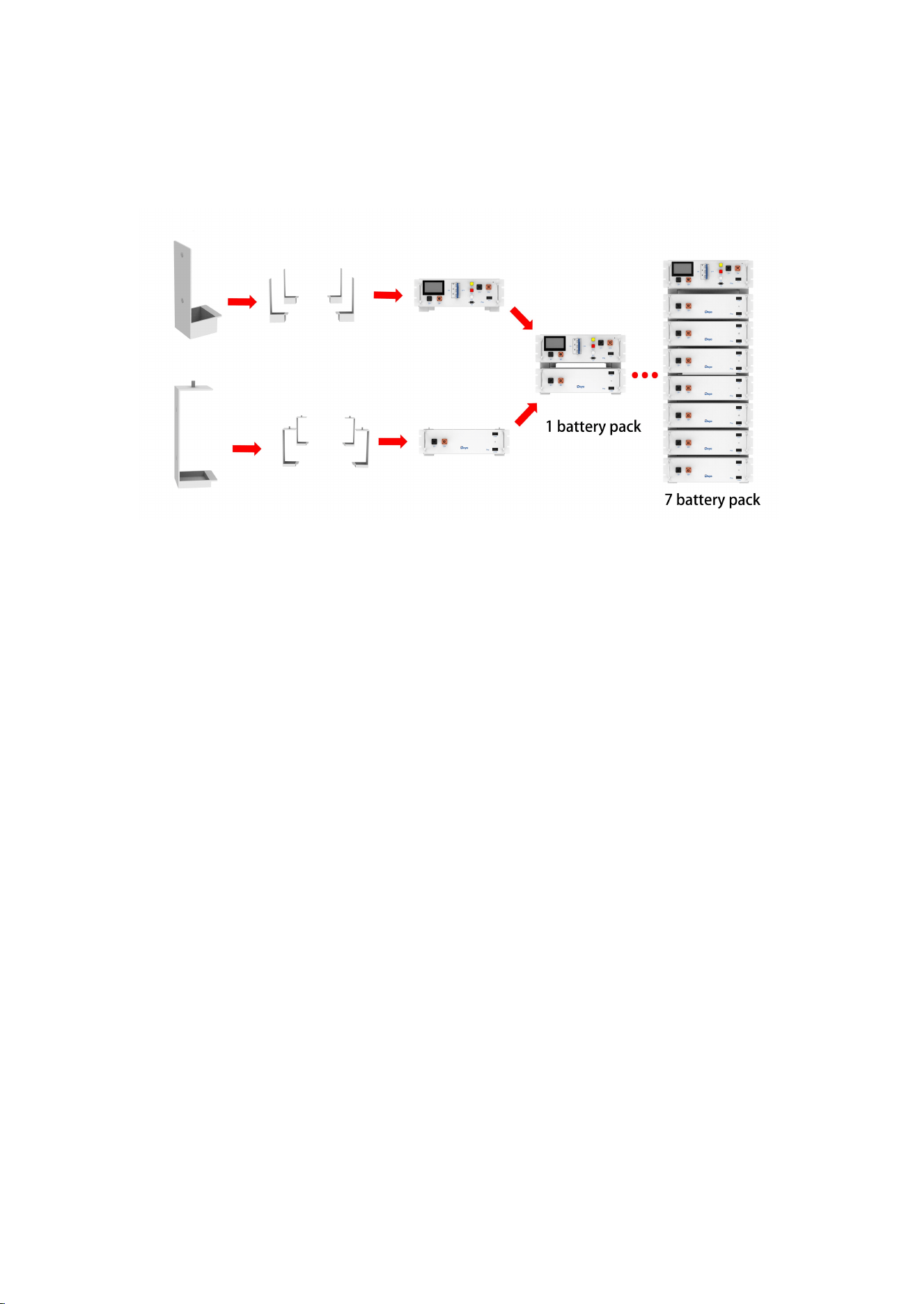
According to customer needs, if the customer needs less than 8 battery packs (1~7
battery packs +1 high voltage box), then the customer can choose a simple rack.
Note: Simple bracket is optional.
The installation Procedure of the simple mounting rack is shown in the figure.
4.5.2 Installation of Rack
1. Take out the two left and right welding frames, and fix the four beams on the upper and
lower sides of the beams with hex combination screws(Broken lacquer flakes and Round
head hexagon socket combination·screws' combination way is in the following figure) and
hex wrenches, respectively, to form a rectangular frame.
2. Fix the upper and lower diagonal supports to the left and right welding frames using round
head hex combination screws and hex wrenches.
3. Screw the base into the bottom plate and secure it with hexagonal wrench or by hand.
4. When installation is complete, stand the rack up.
5. To fix the rack on the wall, use a hexagonal wrench to install the rack fastener on the socket
combination screw hole above the rack and fix it with the socket combination screw. Fix the
other side of the rack with the wall using round head hexagon combination screws. To fix
two racks together, install the rack fasteners on the hexagon socket combination screw holes
above the frame, and fix them together with hexagon socket combination screws and nuts.
Please refer to installation guide for details.
22
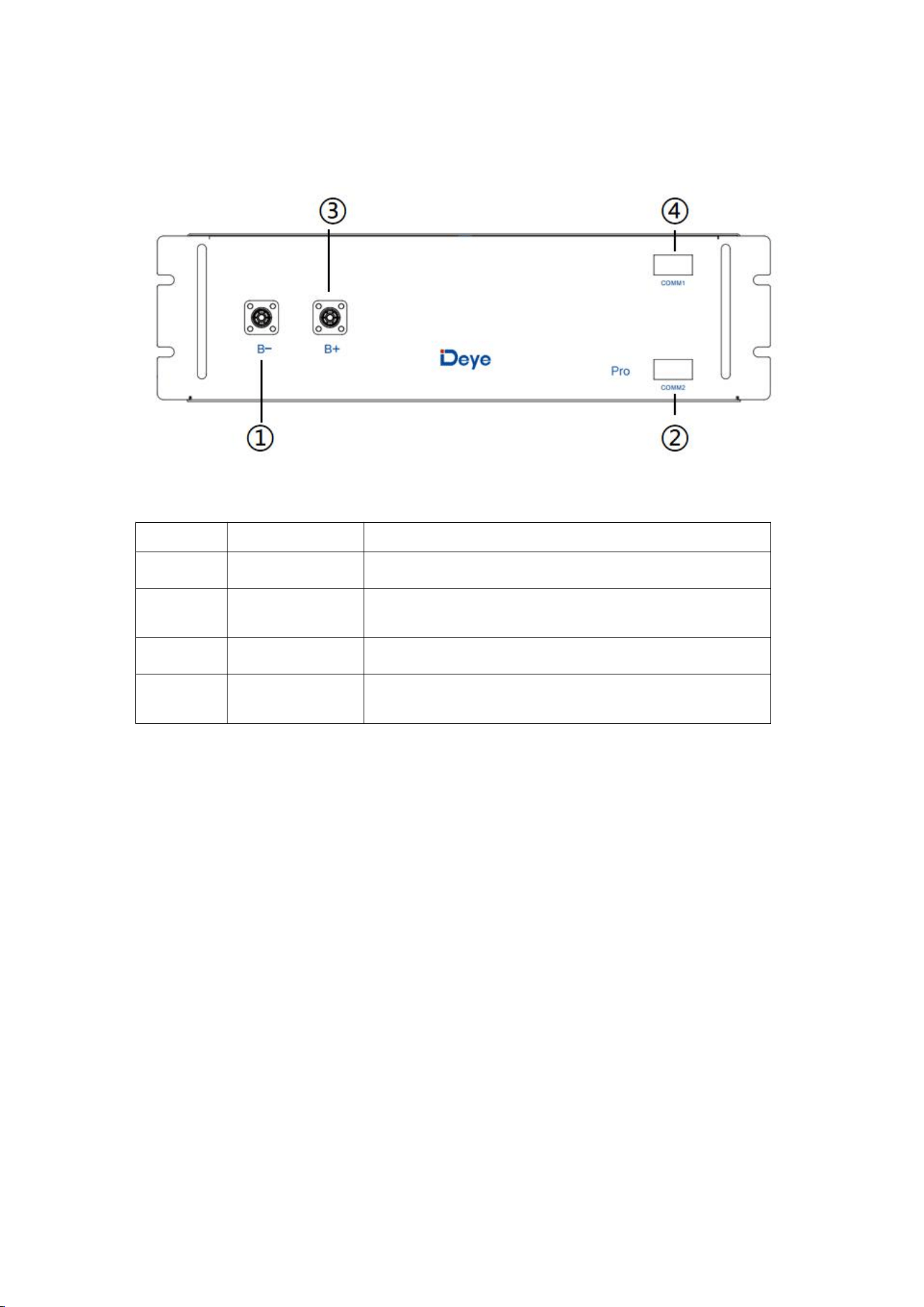
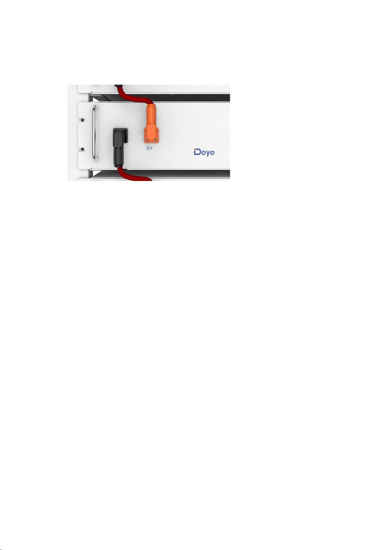
4.6 Description of Battery Module
No.
Name
Description
①
B-
Battery module negative pole (black)
②
COMM2
Connection position of battery module communication
and power supply output
③
B+
Battery module positive pole (orange)
④
COMM1
Connection position of battery module communication
and power supply input
23
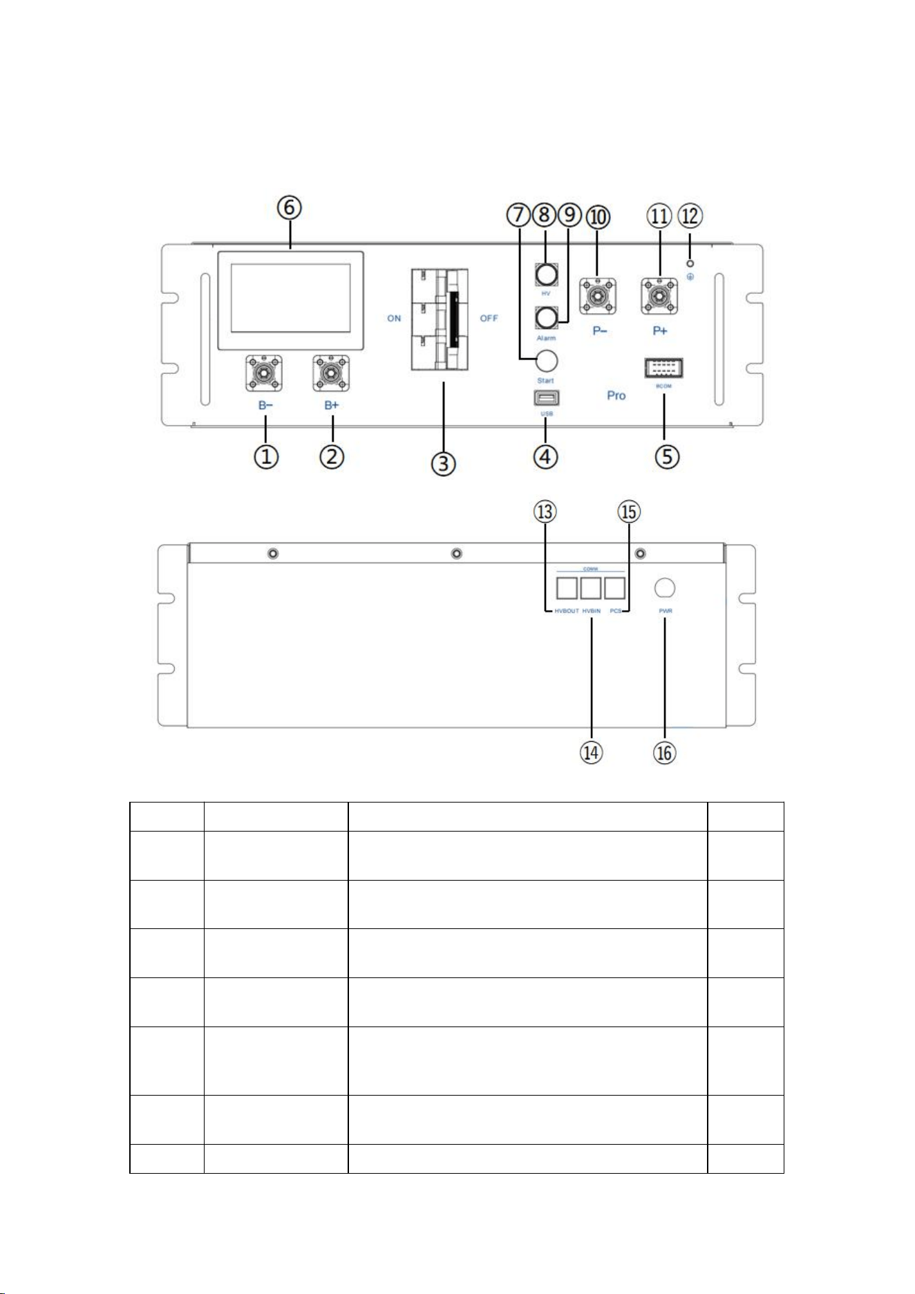
4.7 Description of High-Voltage Control Box
No.
Name
Description
Position
①
B-
Connection position of the common negative pole
of the battery (black)
Front
②
B+
Connection position of the common positive pole of
the battery (orange)
Front
③
Air switch
Used to manually control the connection between
the battery rack and external devices.
Front
④
USB
BMS upgrade interface and storage expansion
interface
Front
⑤
BCOM
Communicative connection with the first battery
module; and Providing 12VDC power for the first
battery module.
Front
⑥
Human-machine
interface (HMI)
Display some important battery information.
Front
⑦
START
A start switch of 12VDC power inside the high-
Front

24
voltage control box
⑧
HV light indicator
High-voltage hazard indicator (yellow)
Front
⑨
ALRM light
indicator
Battery system fault alarm indicator (red)
Front
⑩
PCS-
Connection position of PCS negative pole (black)
Front
⑪
PCS+
Connection position of PCS positive pole (orange)
Front
⑫
Grounding wire
identification
Connection to the battery rack and the ground point
Front
⑬
OUT COM
Connection position with next BOS-G-PDU-2
communication output
Rear
⑭
IN COM
Connection position with previous BOS-G-PDU-2
communication input
Rear
⑮
PCS COM
PCS COM battery communication terminal: (RJ45
port) follow the CAN Protocol (default baud rate:
500bps) and RS485 Protocol (default baud
rate:9.6bps), used to output battery information to
the inverter.
Rear
⑯
POWER
Connection position of external 12VDC power
supply
Rear
25
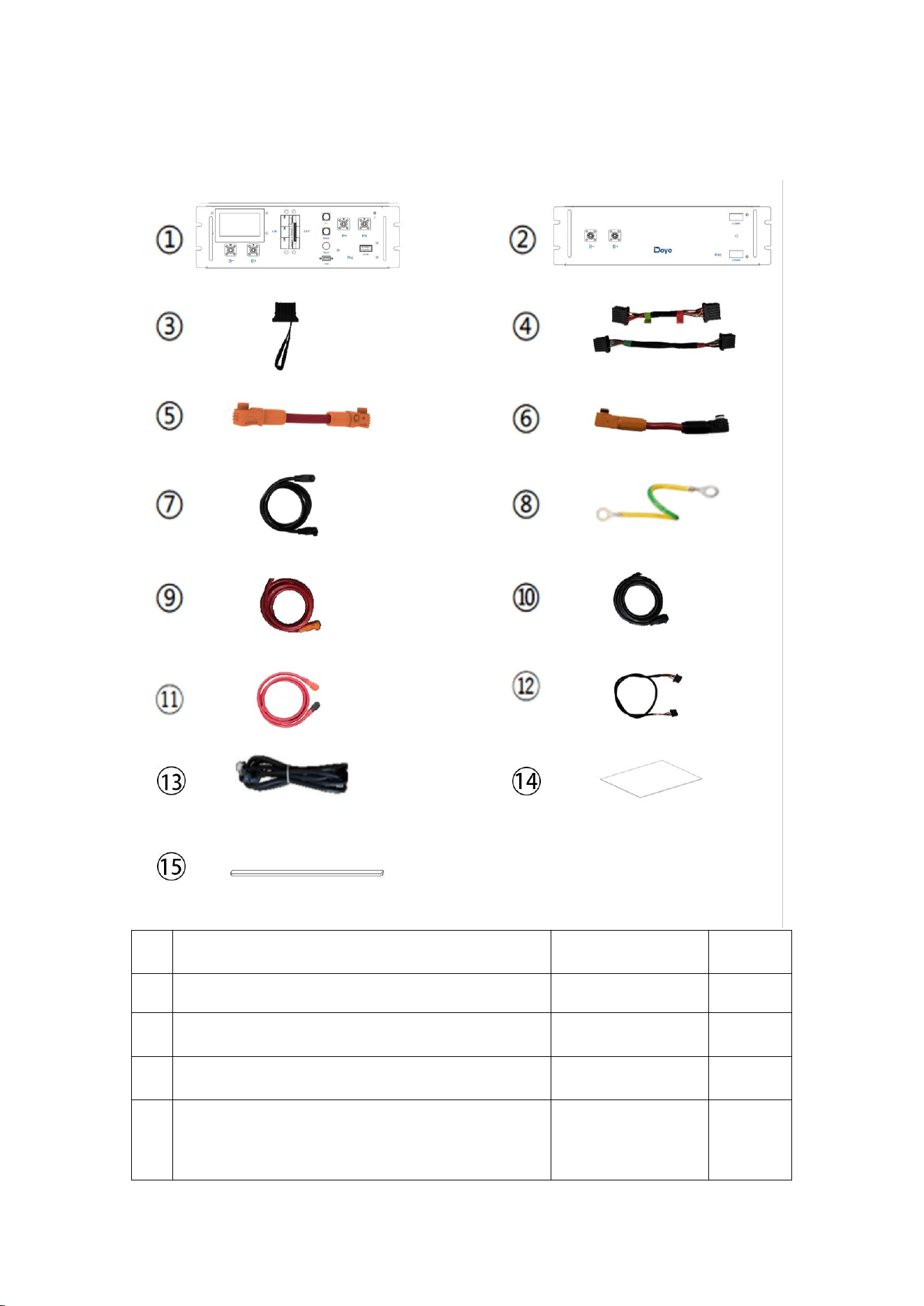
4.8 Description of Battery Module in Rack
No.
Description
quantity
①
High-voltage control box 1000V/100A
1
②
5.12kWh battery module (general)
17
③
120ohm terminal resistor
1
④
Communication cable (160 mm for battery module,
250 mm for high-voltage control box) CAT5E FTP
26AWG black
Standard
16

26
⑤
140 mm positive power cord of high-voltage control
box UL 10269 4AWG red
Standard
1
⑥
200 mm power cord of battery module UL 10269
4AWG red
Standard
15
⑦
The negative power cord of the high-voltage control
box 2150mm UL 10269 4AWG black
Standard
1
⑧
140 mm ground wire A (ground wire B for external
connection of battery rack is not Provided) UL 1015
10AWG yellow green
Standard connecting
cable A (connecting
the high-voltage
control box)
1
⑨
Connected to external PCS positive power cord
(EPCable2.0) UL 10269 4AWG red
Standard
1
⑩
Connected to external PCS negative power cord
(ENCable2.0) UL 10269 4AWG black
Standard
1
⑪
1000mm power cable between the two battery racks
Standard
1
⑫
1000mm communication cable between the two
battery racks
Standard
1
⑬
2000mm network cable
Standard
1
⑭
Heat insulation foam
Standard
2
⑮
Rubber pad
Standard
2
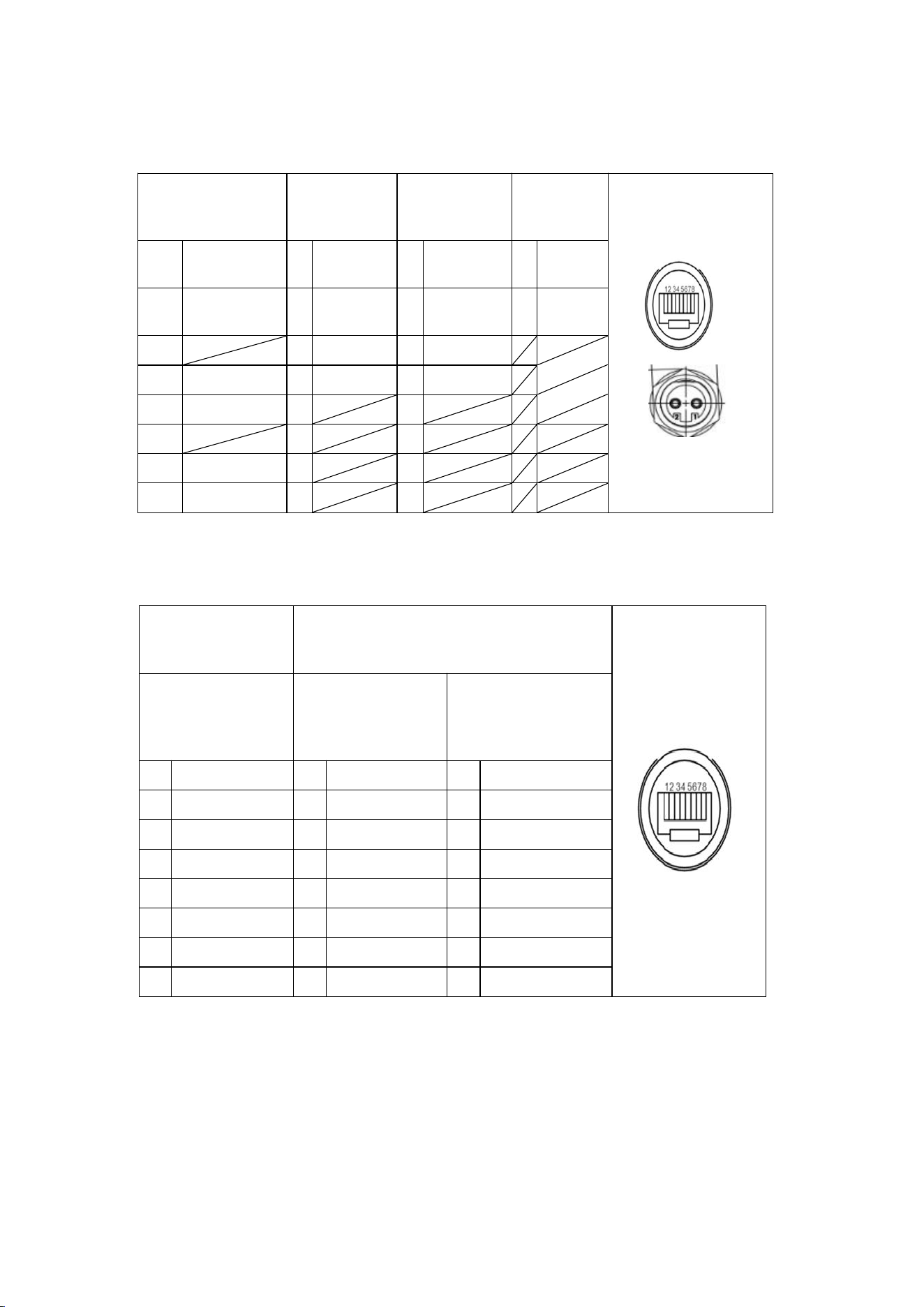
27
Definition of PCS
communication
interface
Racks in
parallel IN
Racks in
parallel OUT
Definition
of power
1
485B-
1
BMS_CAN
L
1
BMS_CAN
L
1
12V
2
485A+
2
BMS_CAN
H
2
BMS_CAN
H
2
GND
3
3
DI+
3
DO2+
4
PCANH
4
DI-
4
DO-
5
PCANL
5
5
6
6
6
7
485A+
7
7
8
485B-
8
8
Definition of the
high-voltage control
box interface
Definition of the battery module interface
Definition of BMS-
BMU
communication
interface
Definition of the
upper BMU
interface
Definition of the
lower BMU interface
1
BMU_CANL
1
BMU_CANL
1
BMU_CANL
2
BMU_CANH
2
BMU_CANH
2
BMU_CANH
3
DO+
3
DI+
3
DO+
4
DO-
4
DI-
4
DO-
5
GND
5
GND
5
GND
6
GND
6
GND
6
GND
7
12V
7
12V
7
12V
8
12V
8
12V
8
12V
28
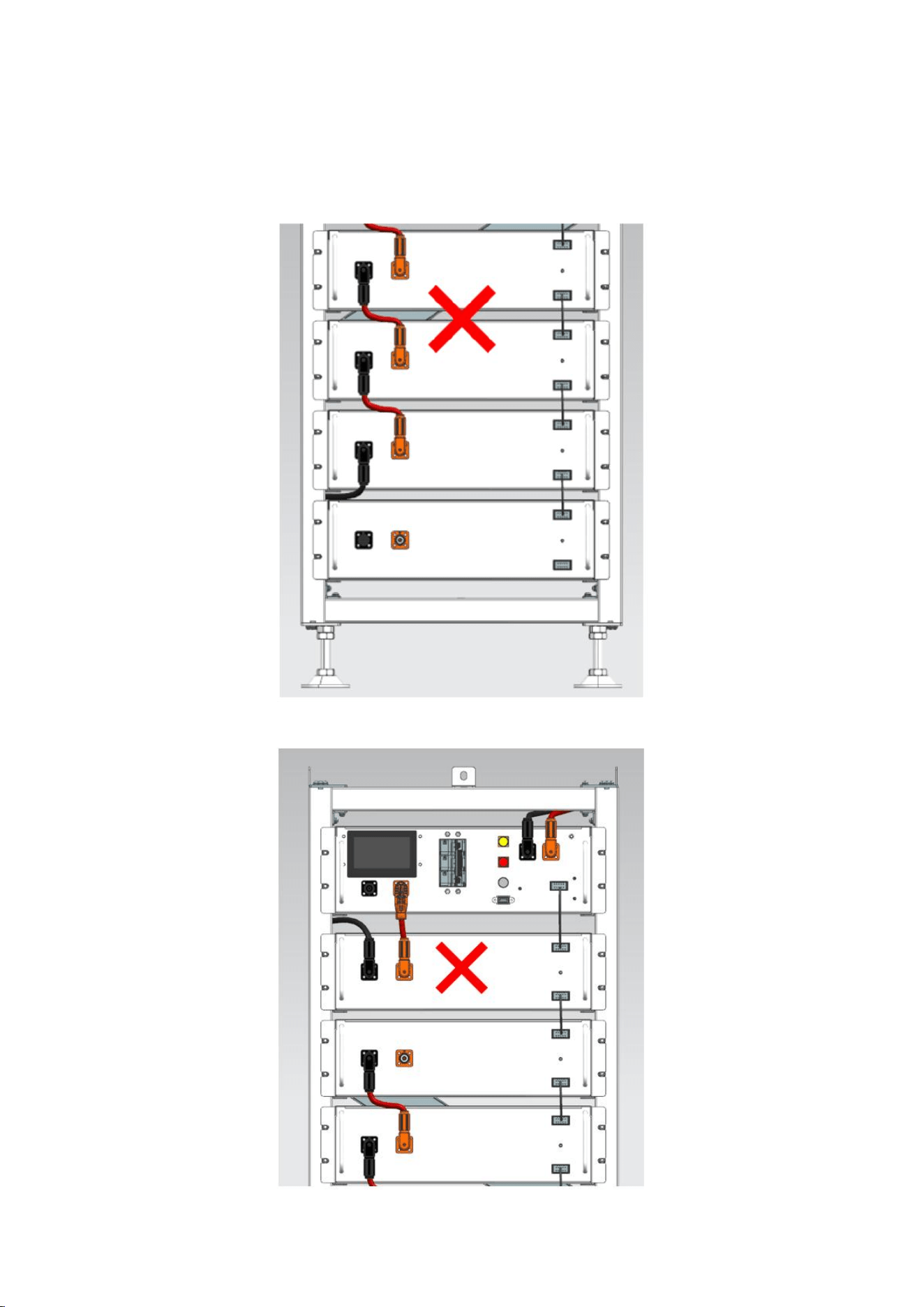
4.9 Wrong wiring method
The first incorrect wiring method
The second incorrect wiring method
29
4.10 Installation of the Battery Module to the Rack
Insufficient or no grounding may cause an electric shock. Device malfunctions, and
insufficient or no grounding may cause device damage and life-threatening electric shocks.
Note: Before installing the battery, please turn the manual switch of the high-voltage
control box to the off position.
Note: Before installing the battery, the minimum distance to the surrounding buildings or
other objects is 5mm.
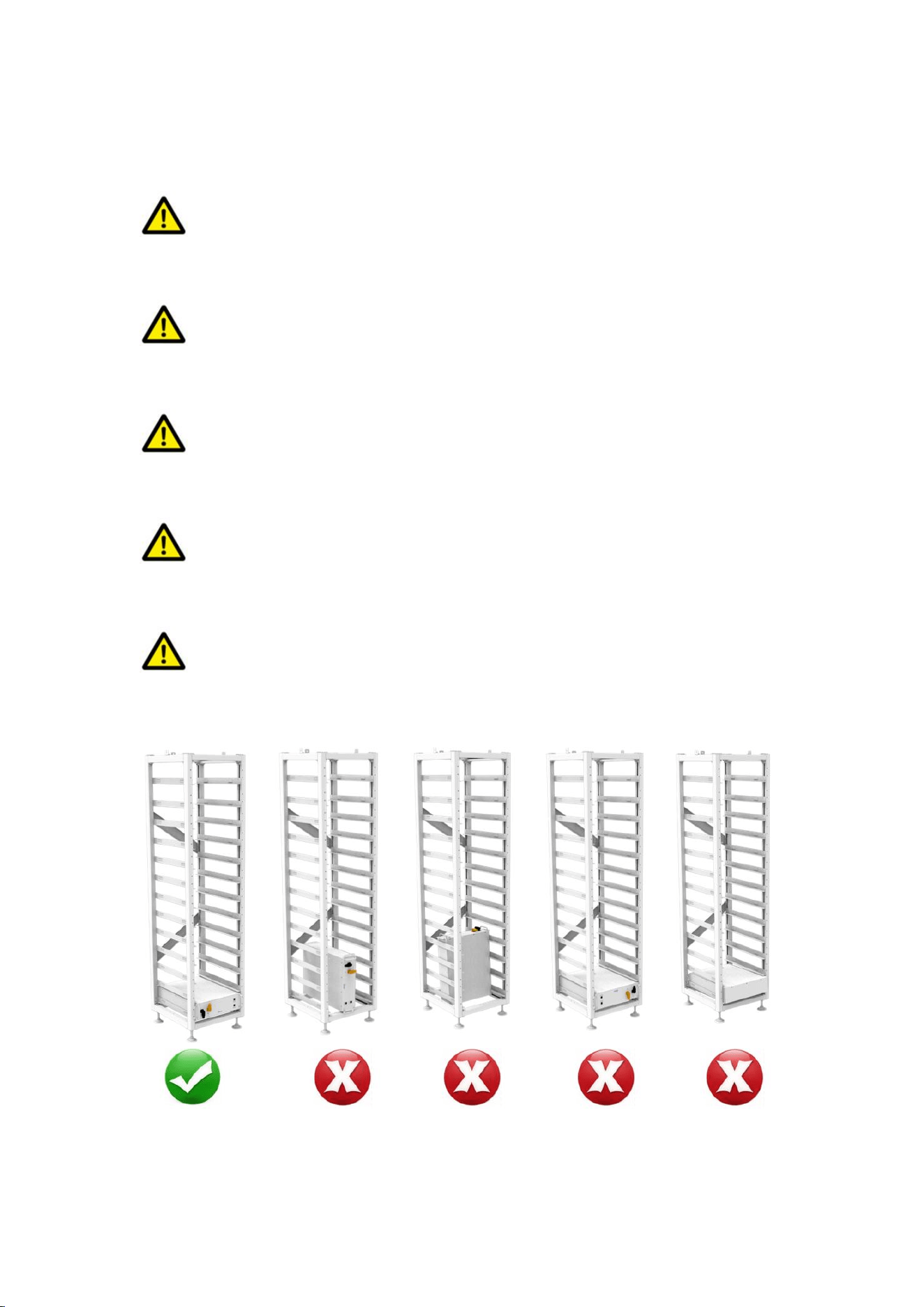
CAUTION
Remember that this battery is heavy! Please be careful when lilting out from the package.
CAUTION
Note the allowable installation modes:
30
1. Insert the first battery module into the battery module rack at the bottom cluster rack; then
in the order from bottom to the top, continue the installment in the same way till it reaches
the twelfth floor. On the thirteenth floor, insert the slide of the cabinet at the top of the rack
into the high-voltage control box.
2. After the battery module and control box is inserted into the rack, use M6*20 hex socket
combination screws to fix all the lugs of the battery module and control box on the side
beam in turn.
3. Note: During the installation of the cluster stand, the thermal insulation cotton is installed at
the bottom of the cluster stand, as shown in the figure:
31
4.10.1 Cable connection
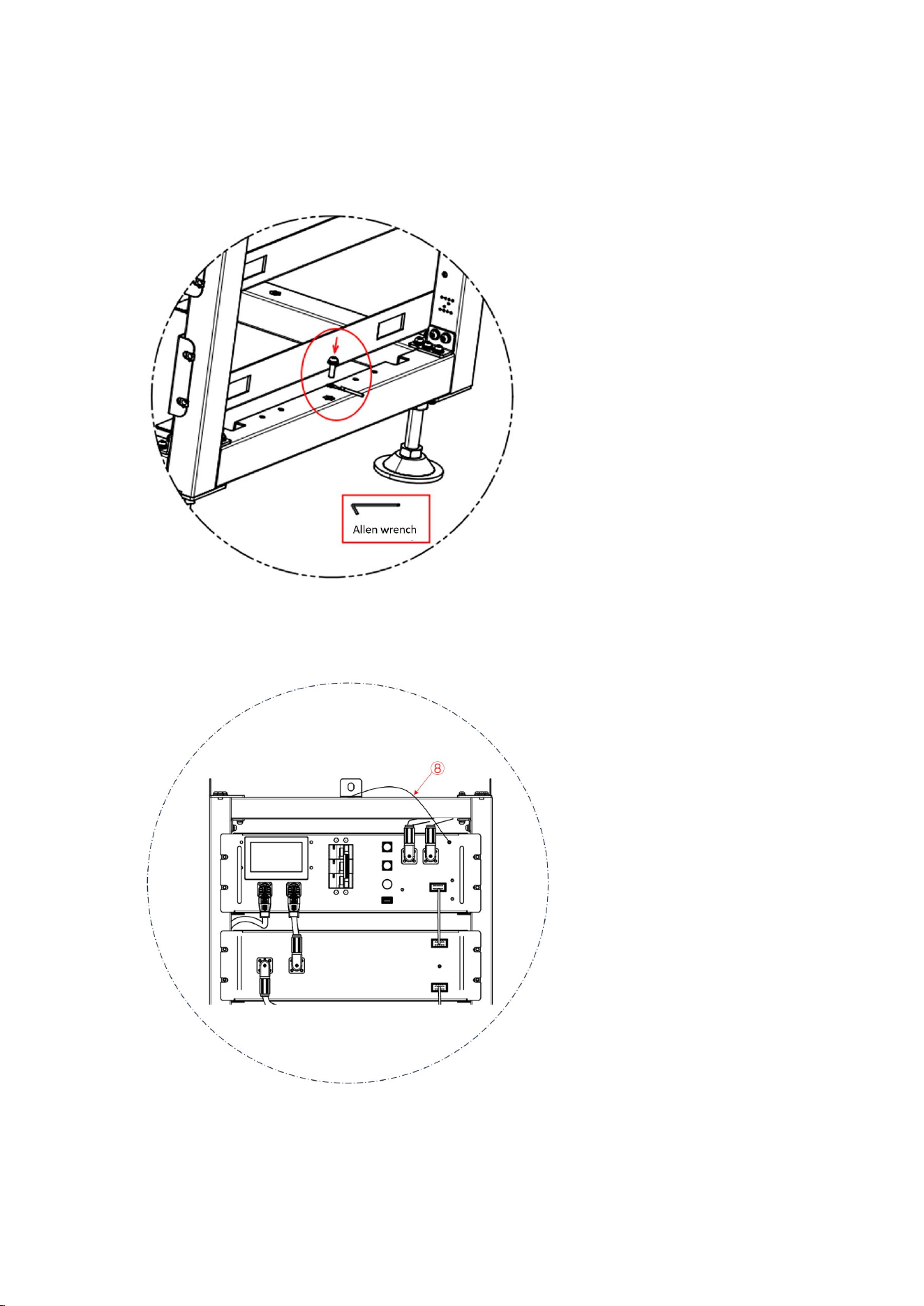
1. Grounding description
Twist one end of the cable harness ⑧ in 4.8 to the wiring position shown in the figure, and twist
the other end to the ground copper bar of the PDC using an Allen wrench.
For details, see Section 4.8 Cables ⑧

32
Connect one end of the ⑧ cable to the Power Distribution Cabinet ground hole using an M4
screw and the other end to the cluster holder hole using an M6 screw.
Take out the ground wire A and connect one end of it to the M4 rivet nut of the high-voltage
control box panel, and the other end to any M6 screw hole of the cross beam above the rack.
Take out the ground wire B (user need to prepare in advance) and connect one end of it to any
M6 screw hole of the cross beam under the rack, and the other end to the customer's grounding
point. (The length of the ground wire B is determined based on the customer's condition.)
33
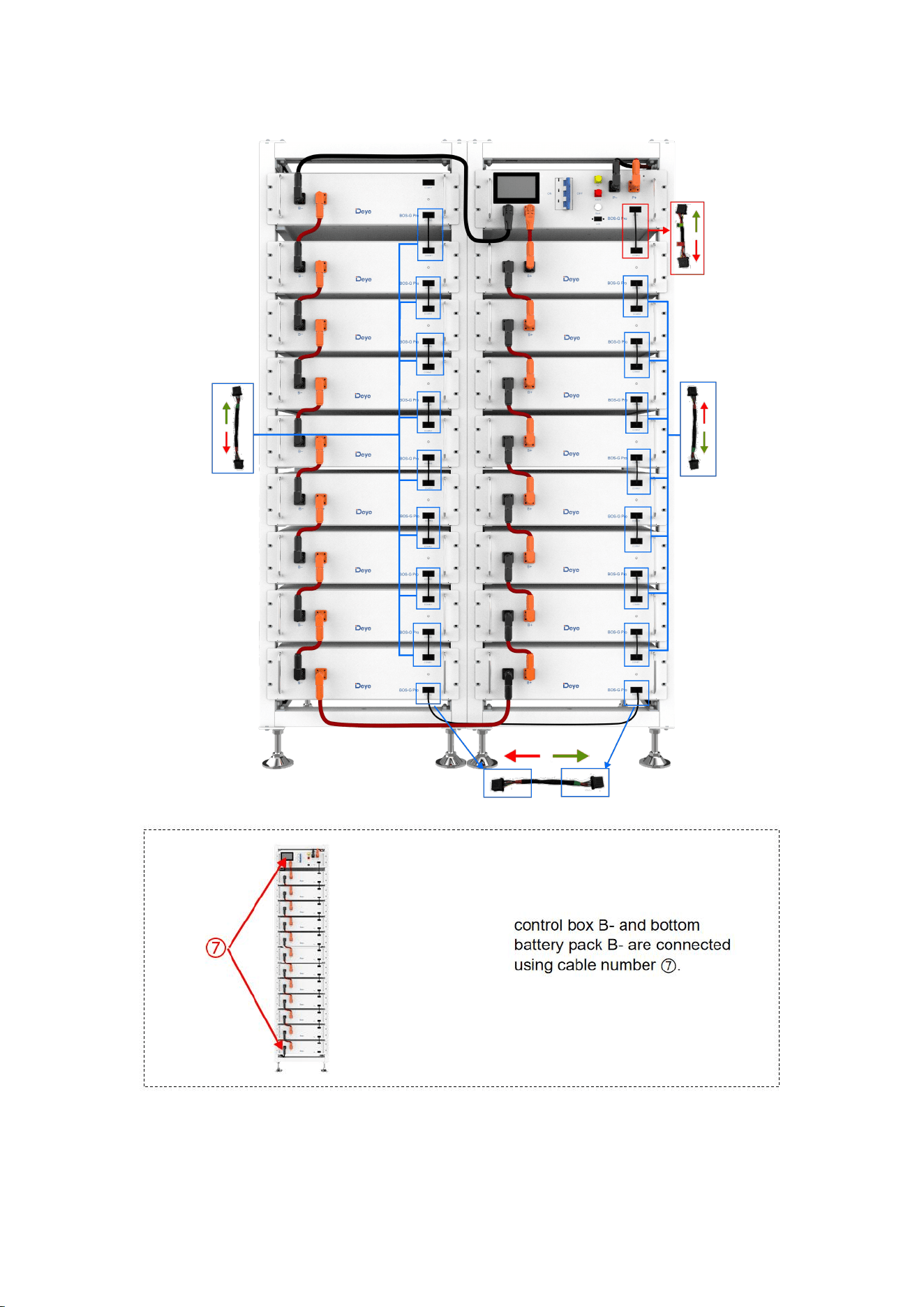
4.10.2 Battery installation cable Description
For details on how to connect all cables, see Section 4.8.
34

35
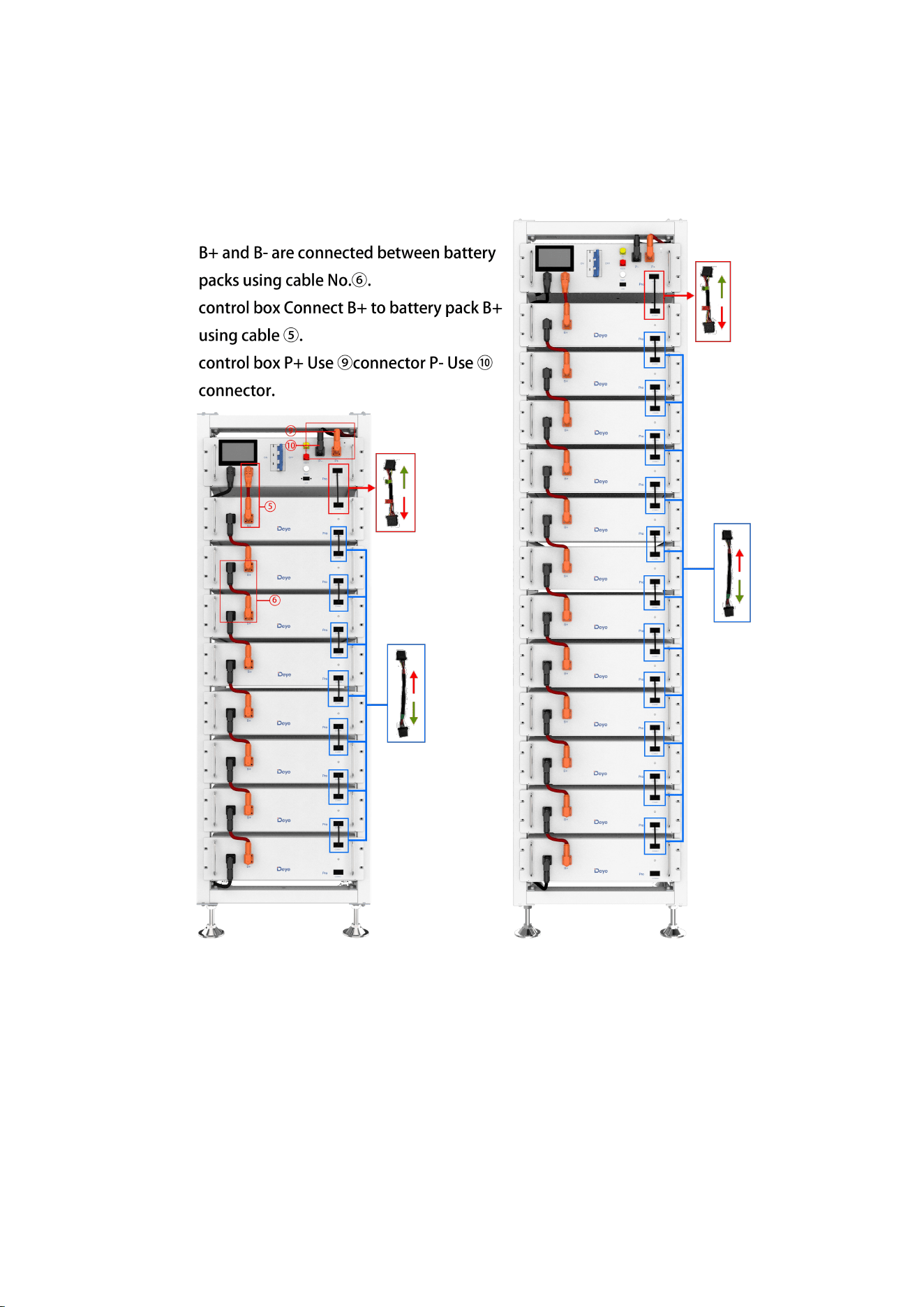
4. After the battery module is placed in the control box, take out a 250 mm communication
cable to connect the communication port of the battery module and the high-voltage
control box, and 11x160mm communication cables to connect the battery module
communication port (IN-OUT) from top to bottom.
The OUT communication port of the last battery module does not need to be connected to
communication cable. Instead, this port is sealed with a 120ohm terminal resistor.
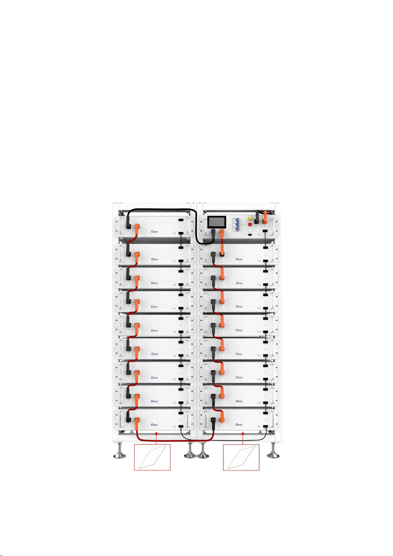
5. Take out a 140 mm positive power cord and connect the positive pole of the battery module
at the top to the positive pole of the high-voltage control box. Take out 11x200mm battery
module power cords and connect the power ports (B- to B+) in a top to bottom order to
form a series circuit. For aesthetics, connect the negative power pole of the first battery
module to the negative power pole of the high-voltage control box from the bottom of the
battery module to the back of the rack. On the back of the rack, a plane-head-shaped tie is
used to secure the cable harness.
6. Take out the external positive power cord EPCable2.0 and external negative power cord
ENCable2.0, and plug them into PCS interfaces, respectively.
7. Take out the ground wire A and connect one end of it to the M4 rivet nut of the high-voltage
control box panel, and the other end to any M6 screw hole of the cross beam above the rack.
Take out the ground wire B (user need to prepare in advance) and connect one end of it to
any M6 screw hole of the cross beam under the rack, and the other end to the customer's
grounding point. (The length of the ground wire B is determined based on the customer's
condition.)
4.11 Battery cluster connected to inverter
For the Australian Market, an over-current Protection and isolation device that isolates both
positive and negative conductors simultaneously is required between the battery system and
inverter
Battery cluster connected to inverter
Notice: The length of the communication line between the inverter and the battery should not
exceed 30m.
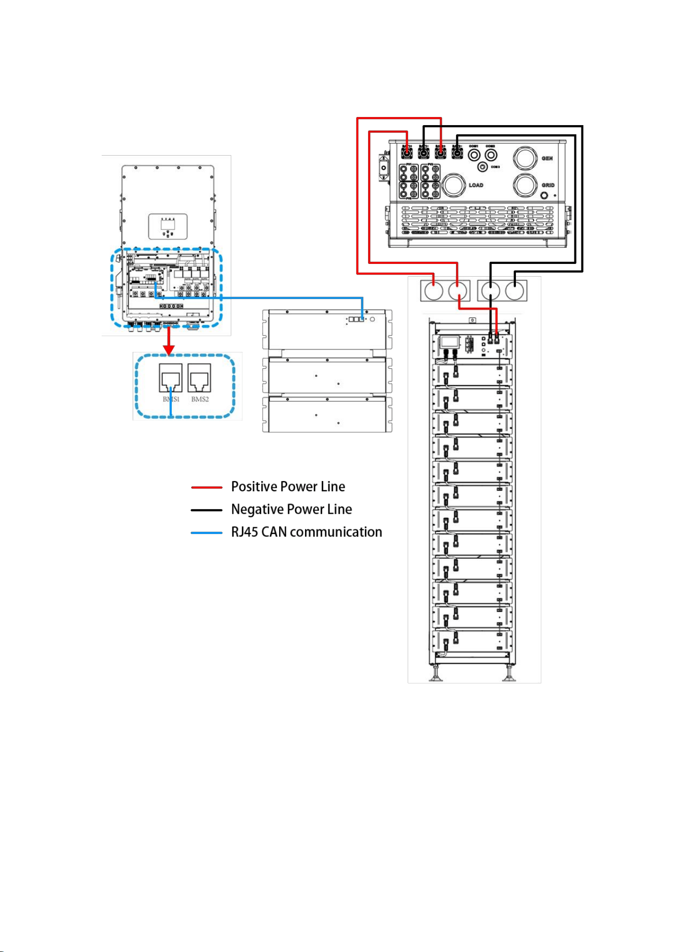
36
Single battery cluster connected to inverter
37
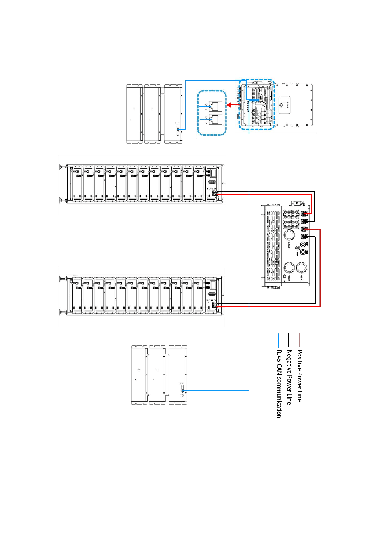
Two battery clusters connected to the inverter
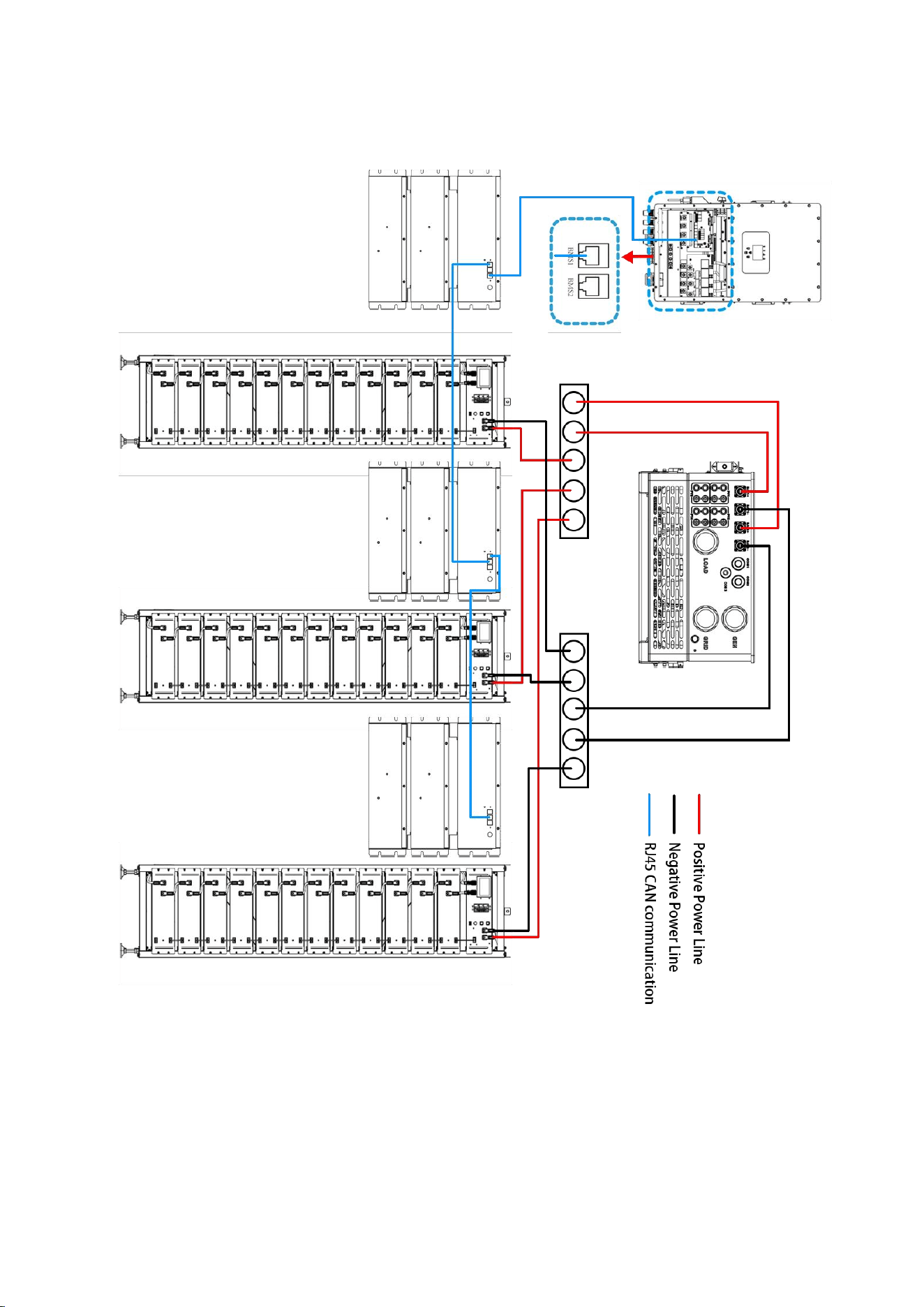
38
Three battery clusters connected to the inverter
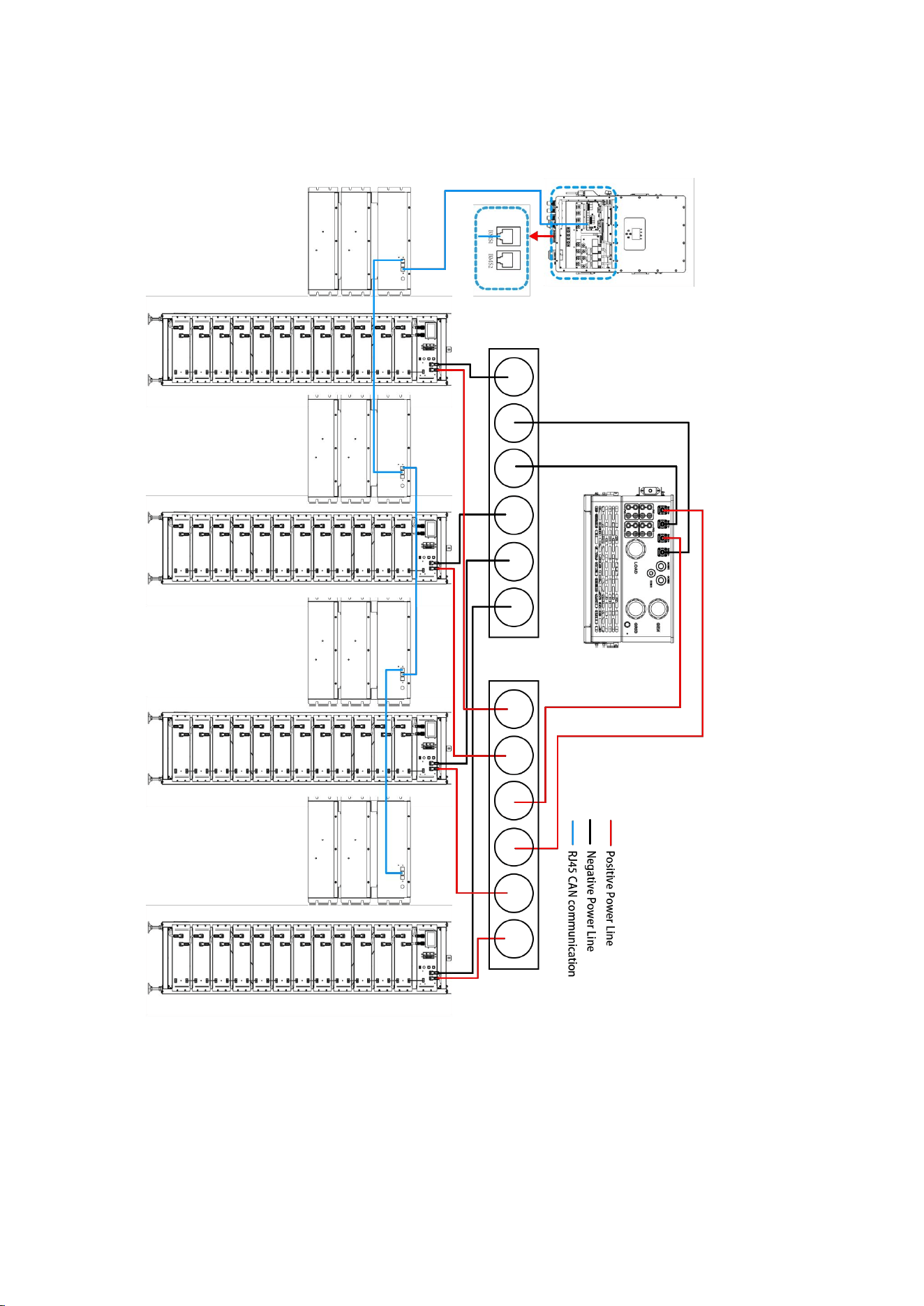
39
Multiple battery packs are connected to the inverter
The number of battery packs in each cluster must be the same in each group, and the
number of battery packs in group A and Group B can be different.

40
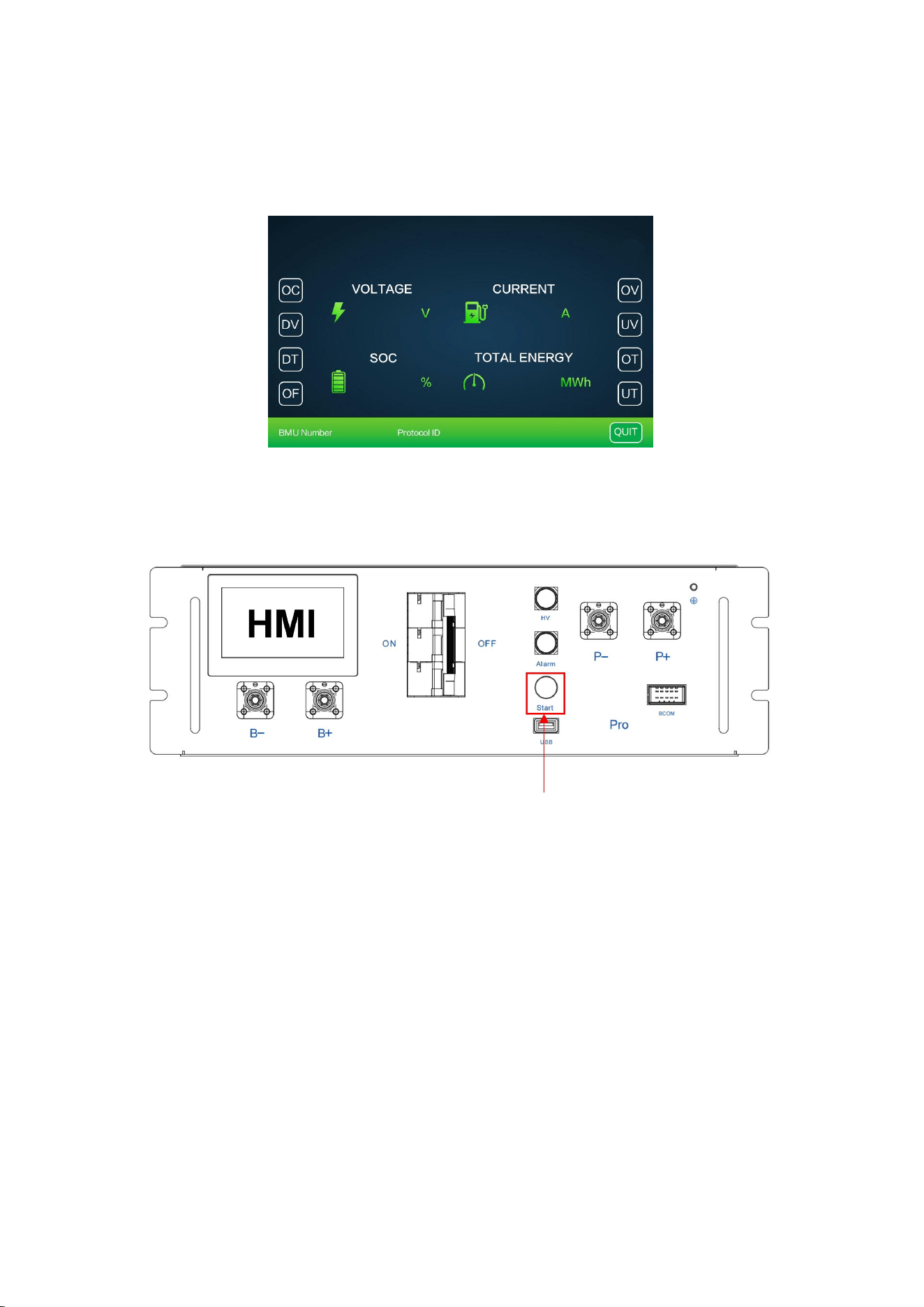
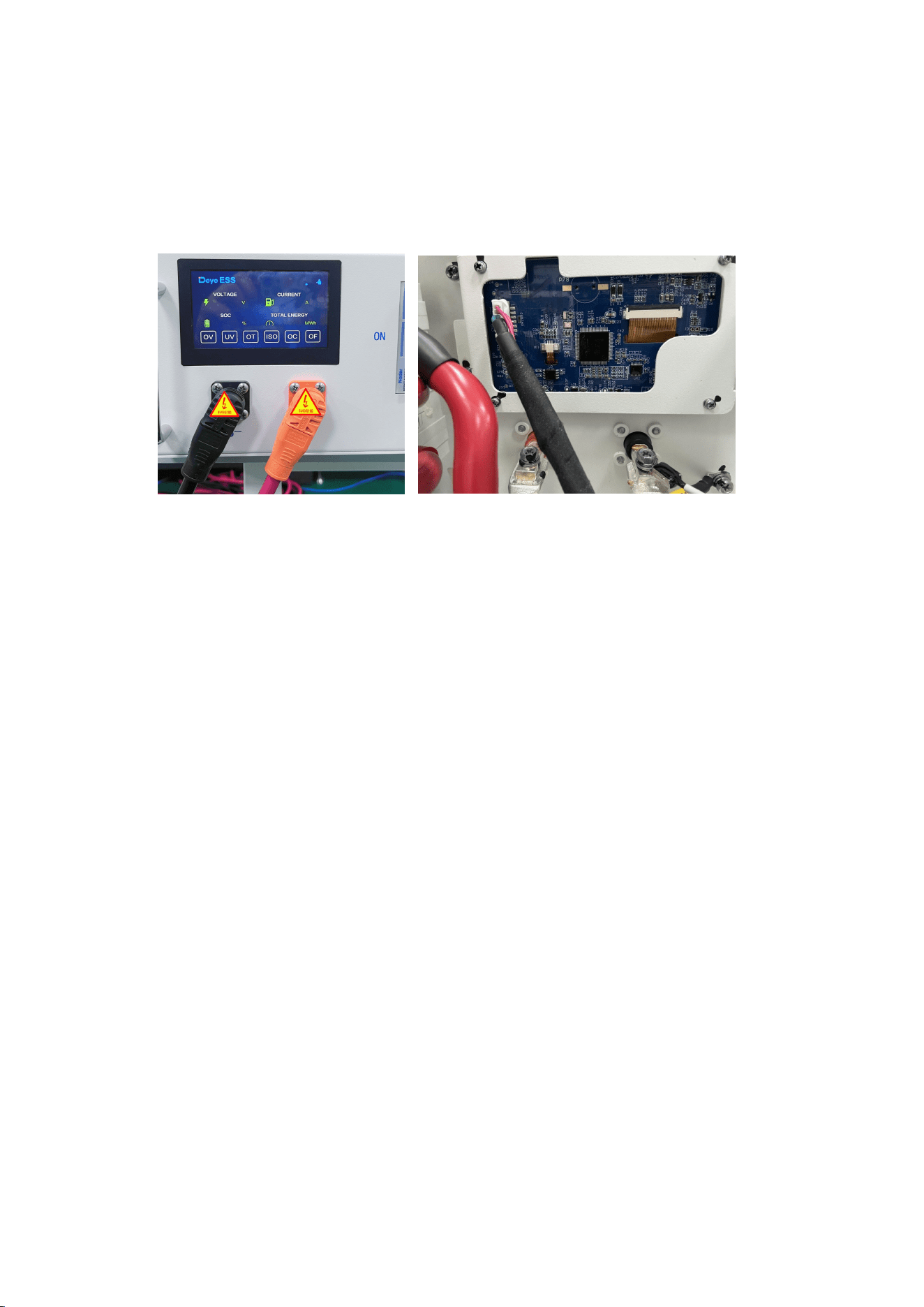
4.12 System startup and shutdown
Startup Procedure
1) After connecting the battery cables, press the air switch button on the high-voltage control
box to turn OFF to ON.
2) Press the start button and wait for the screen to light up.
3) Complete boot
Shutdown Procedure
1) Press the start button again and wait for the screen to go off.
2) Press the air switch button ON the high pressure control box and set the "ON" to the "OFF"
position.
3) Complete shutdown
Description of external circuit breakers between inverter and battery system
Turn on the circuit breaker and then start the battery pack.
Turn off the circuit breaker after the battery pack is closed.
41
4.13 Procedure for configuring battery packs
Steps:
1. After connecting the battery cables, press the air swim key to enter the main interface of
system maintenance. The operation shall be performed by a Professional. Tch button on the
high-voltage control box to turn OFF to ON.
2. Press the start button and wait for the screen to light up.
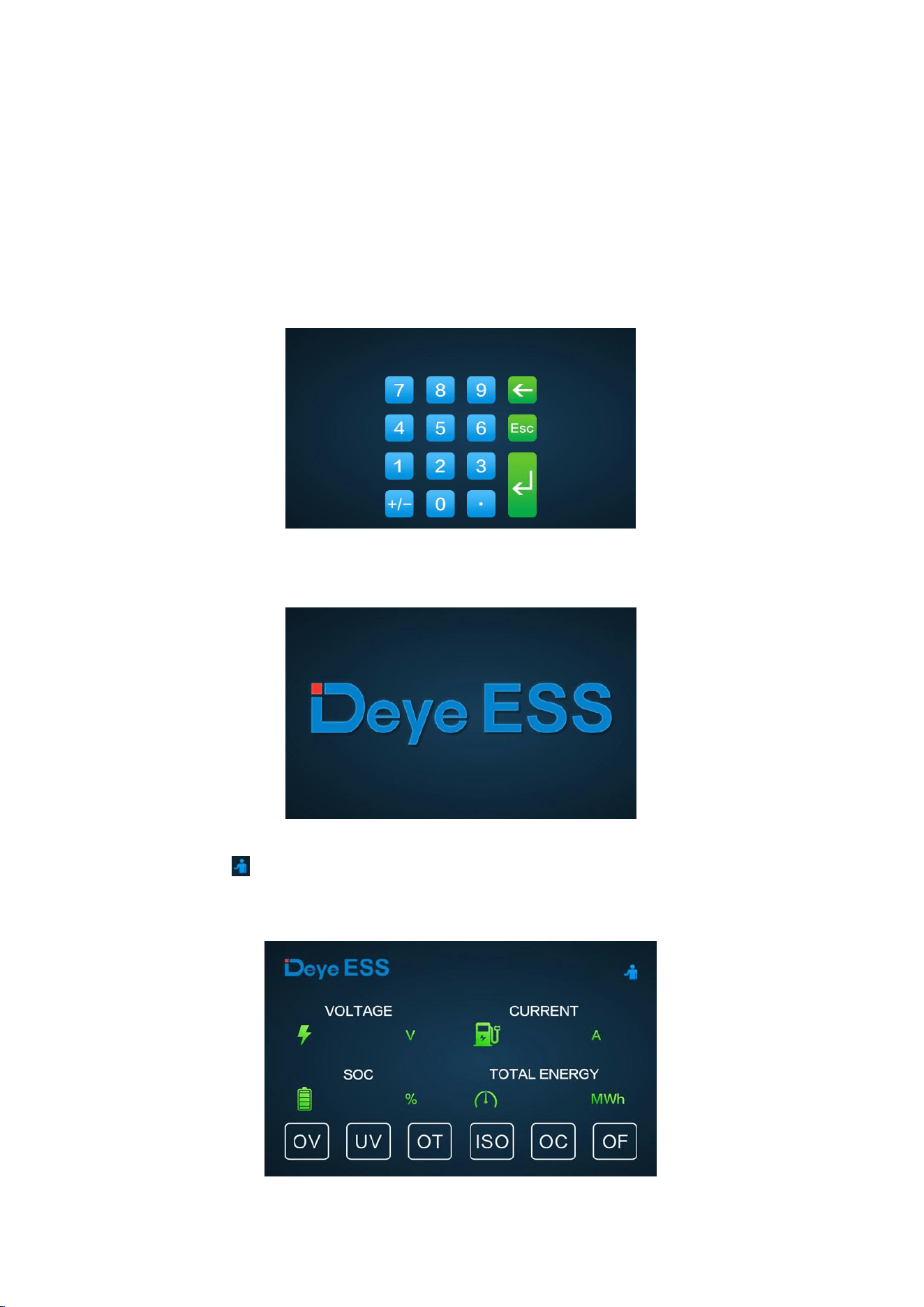
3. Click the icon on screen to enter the maintenance system password confirmation
interface.
42
4. Enter the password 123 and press the Confir
5. Click
“
BMU Number
”
in the lower left corner, enter the number of packs in system and
click
“
OK
”
to finish configuring the number of packs.
6. After the setting is successful, you need to restart. Click the Start button to restart, wait for
about 8 seconds until the yellow HV light indicator comes on.
4.14 External 12V Power Supply of High-Voltage Control Box
To operate the high-voltage control box with an external 12V power supply, please contact our
service personnel. Hotline: +86 0574 8612 0560, Email: service-ess@deye.com.cn .
In the factory configuration, the high-voltage control box is supplied with working voltage from
an internal power supply unit. If your plan requires an external 12V power supply, an adaptive
version and a high-voltage control box can be Provided as requested. Please contact our after-
sales service personnel for details.
43
5. BOS-G Pro User Interface
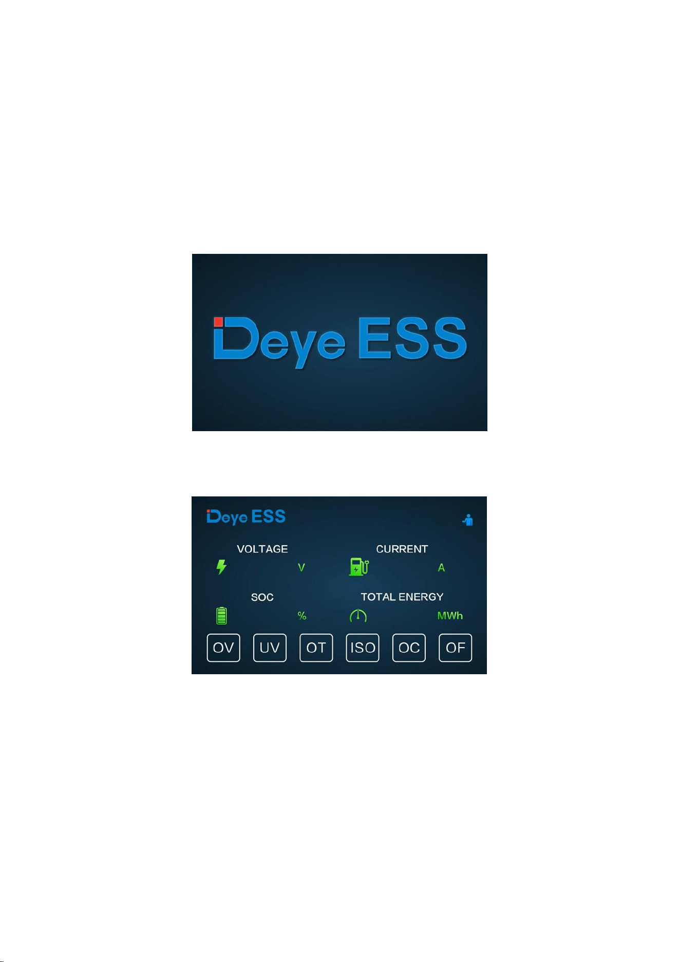
5.1. Main Interface
The default interface will appear after powering on. If the screen is not touched for more than 13
minutes, it will darken and the default interface replaces the other interface. Click this screen to
enter the user interface.
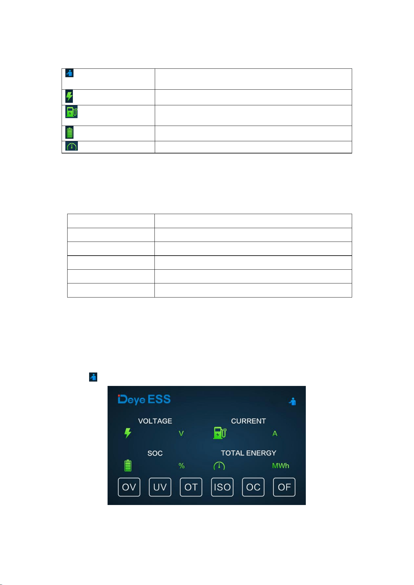
5.2 Description of User Interface
44
(1) Basic Parameters
(2) Fault Indication:
When the corresponding fault type occurs, the red background indicator on the screen will light
up.
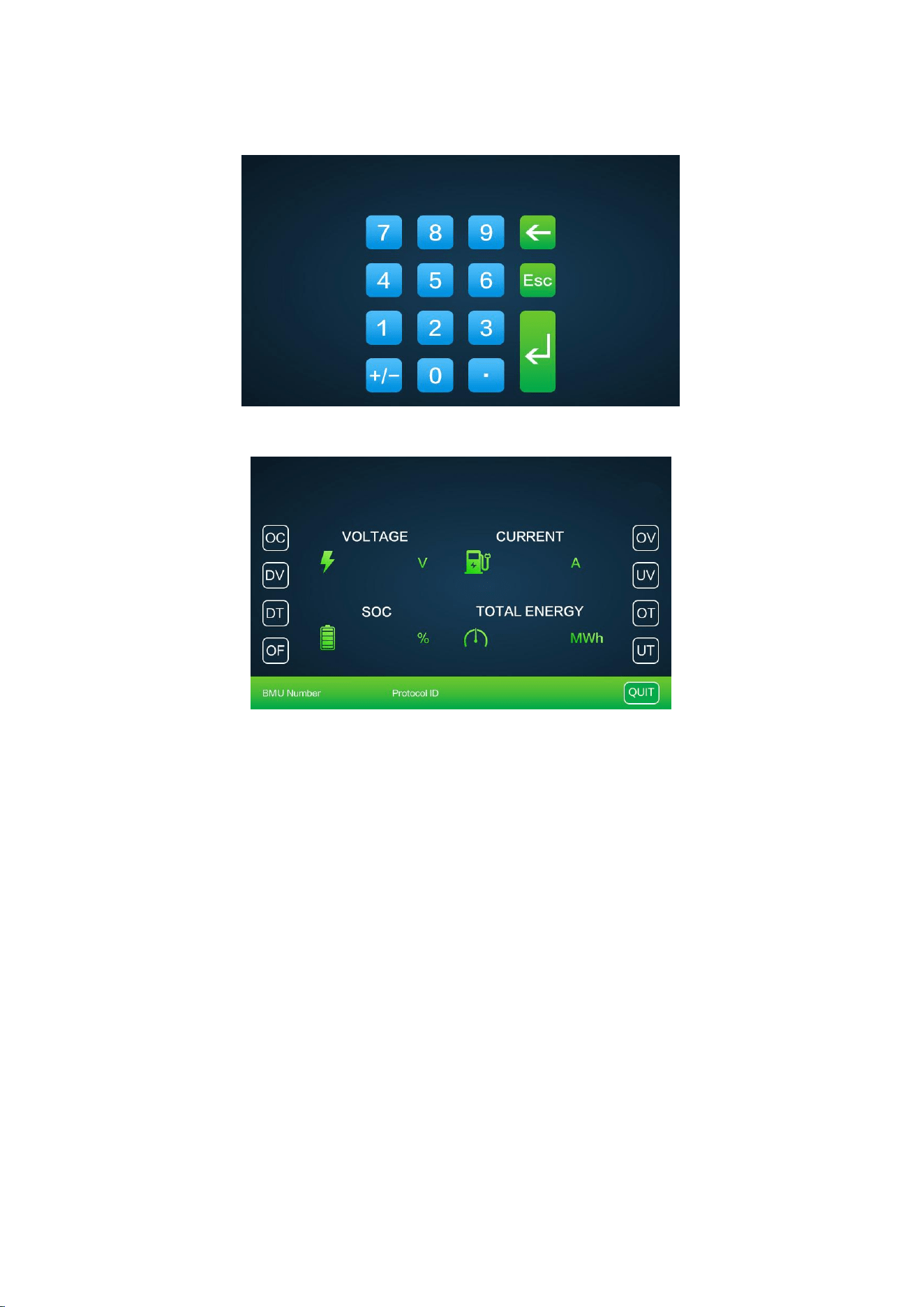
5.3 Fault viewing interface
Power switch: Once the device is Properly installed and the cables are Properly connected, first
set the circuit breaker to the ON position, and then press the Start button to turn on the device.
Click the icon on screen to enter the maintenance system password confirmation interface.
System maintenance
icon
Click this icon to enter the system maintenance
interface.
Voltage
Total battery voltage
Current
Battery current, the positive value representing
discharge, the negative value representing charge
SOC
Battery remaining energy
Total energy
Accumulated discharging energy
OV
Overvoltage
UV
Undervoltage
OT
Overtemperature
ISO
Insulation failure, there is a risk of current leakage
OC
Charging overcurrent
OF
Other faults
45
Enter the password 123 and press the Confirm key.
The enter main interface of system. The operation shall be performed by a Professional.
Fault warning
OV turns red: expression overvoltage, click OV to view the detail fault.
UV turns red: expression undervoltage, click UV to view the detail fault.
OT turns red: expression overtemperature, click OT to view the detail fault.
ISO turns red: expression Insulation failure, there is a risk of current leakage, click ISO to view the
detail fault.
OC turns red: expression charging overcurrent, click OC to view the detail fault.
OF turns red: expression other faults, click OF to view the detail fault.
46
5.4 Maintenance Interface
For safety, please unplug the power cord of the positive and negative interfaces before
maintenance.
Note: When inserting the SD card, unplug the battery power cord and manually turn the air
switch to the off position.

47
6. BOS-G Pro fault description
Different types of faults are below:
System faults
Fault types
Trigger conditions
Charge over-current
alarm
Exceeding the parameter set value and set time
(More than 105A, 2s; more than 125A, 5s; more
than 140A, 2s; lower than 5℃,
set value*0.5)
Charge over-current
Protection
Discharge over-current
alarm
Discharge over-current
Protection
Charge overtemperature
alarm
Exceeding the parameter set value and set time
(>45
℃
, 2s)
Charge overtemperature
Protection
Exceeding the parameter set value and set time
(>50℃, 2s)
Discharge
overtemperature alarm
Exceeding the parameter set value and set time
(>50℃, 2s)
Discharge
overtemperature
Protection
Exceeding the parameter set value and set time
(>55
℃
, 2s)
Charge under
temperature alarm
Exceeding the parameter set value and set time
(<5
℃
, 2s)
Charge under
temperature Protection
Exceeding the parameter set value and set time
(<0
℃
, 2s)
Discharge under
temperature alarm
Exceeding the parameter set value and set time (<-
10℃, 2s)
Discharge under
temperature Protection
Exceeding the parameter set value and set time (<-
20
℃
, 2s)
Excessive differential
voltage alarm
Exceeding the parameter set value and set time
(>500mv, 2s)
Excessive differential
voltage Protection
Exceeding the parameter set value and set time
(>800mv, 2s)
Excessive differential
temperature alarm
Exceeding the parameter set value and set time
(>10
℃
, 2s)
Excessive differential
temperature Protection
Exceeding the parameter set value and set time
(>15℃, 2s)
Cell overvoltage alarm
To maintain consistency, cut off the charging
immediately when the full charge calibration rated
voltage of 3.6V is reached. When the voltage drops
to 3.35V, restart it with the turned-off red light
Cell overvoltage
Protection
Cell undervoltage alarm

48
indicator. All Protective red light indicators are
always on!
Cell undervoltage
Protection
Pre-charge resistor
overtemperature alarm
Exceeding the parameter set value and set time
(>55
℃
, 2s)
Pre-charge resistor
overtemperature
Protection
Exceeding the parameter set value and set time
(>65℃, 2s)
Insulation level 1
Exceeding the parameter set value and set time
Insulation level 2
Exceeding the parameter set value and set time
Heating film
overtemperature alarm
Exceeding the parameter set value and set time
(>75
℃
, 2s)
Heating film
overtemperature
Protection
Exceeding the parameter set value and set time
(>80
℃
, 2s)
BMS connector
overtemperature alarm
Exceeding the parameter set value and set time
BMS connector
overtemperature
Protection
Exceeding the parameter set value and set time
BMU connector
overtemperature alarm
Exceeding the parameter set value and set time
BMU connector
overtemperature
Protection
Exceeding the parameter set value and set time
Power loop
overtemperature alarm
Exceeding the parameter set value and set time
Power loop
overtemperature
Protection
Exceeding the parameter set value and set time
SOC too low
Exceeding the parameter set value and set time
Total voltage too high
alarm
Exceeding the parameter set value and set time
Total voltage too high
Protection
Exceeding the parameter set value and set time
Total voltage too low
alarm
Exceeding the parameter set value and set time
Total voltage too low
Protection
Exceeding the parameter set value and set time
Discharge relay adhesion
Relay feedback information state adhesion
Charge relay adhesion
Relay feedback information state adhesion
Heating relay adhesion
High voltage is detected after disconnecting the
heating relay
Limit Protection
Exceeding the parameter set value and set time

49
Note: For more information, please contact us. Email: service-
Abnormal power supply
voltage
Exceeding the parameter set value and set time
Master positive relay
adhesion
Relay feedback information state adhesion
Fuse Blown
No high voltage is detected after the loop relay is
closed
Repeated BMU address
fault
BMU with the same number
INTER-CAN BUS
communication failure
Loss of communication between BMS
PCS-CAN BUS
communication failure
The heartbeat message of the inverter is not
received for a long time
RS485 communication
failure
Inverter RS485 access is not received for a long
time
Abnormal RS485
communication
C
External total voltage
acquisition fault
/
Internal total voltage
acquisition fault
The difference between the acquired internal total
voltage and the accumulated internal total voltage
exceeding the set value
SCHG total voltage
acquisition fault
/
Cell voltage acquisition
fault
The cell voltage acquired is 0
Temperature acquisition
failure
The temperature acquired is -40℃
Current acquisition fault
/
Current module fault
Abnormal Hall current/reference voltage
EEProM storage failure
EEProM write failure during self-test
RTC clock fault
The external RTC failed to enable the charging
function
Pre-charge failure
Pre-charge timeout
Charging voltage too low
The minimum cell voltage is lower than the set
value
BMU lost
BMU message not received for a long time
Abnormal number of
BMU
The number of BMU addresses is different from
the number of set parameters
The RTC clock and the
number of BMUs are
abnormal
Battery pack models ZEN and EVE are available in
the system

50
7. Summary of fault types in BOS-G Pro’s screen and HVESS-Monitor
Abbreviation
Screen Protection event
description
HVESS-Monitor Protection
event description
HVESS-Monitor alarm event
description
OT
BMS southward connector
overtemperature
BMU connector
overtemperature Protection
BMU connector
overtemperature alarm
BMS northward connector
overtemperature
BMS connector
overtemperature Protection
BMS connector
overtemperature alarm
Pre-charge resistor
overtemperature level-2
alarm
Pre-charge resistor
overtemperature Protection
Pre-charge resistor
overtemperature alarm
Heating film
overtemperature level-2
alarm
Heating film overtemperature
Protection
Heating film overtemperature
alarm
Charge overtemperature
level-2 alarm
Charge overtemperature
Protection
Charging overtemperature
alarm
Discharge overtemperature
level-2 alarm
Discharge overtemperature
Protection
Discharge over temperature
alarm
/
Power loop overtemperature
Protection
Power loop overtemperature
alarm
UT
Charge under temperature
level-2 alarm
Charge under temperature
Protection
Charge under temperature
alarm
Discharge under
temperature level-2 alarm
Discharge under temperature
Protection
Discharge under temperature
alarm
OC
Charge overcurrent level-2
alarm
Charge overcurrent Protection
Charge overcurrent alarm
Discharge overcurrent
level-2 alarm
Discharge overcurrent
Protection
Discharge overcurrent alarm
DV
Excessive differential
voltage level-2 alarm
Excessive differential voltage
Protection
Excessive differential voltage
alarm
DT
Excessive differential
temperature level-2 alarm
Excessive differential
temperature Protection
Excessive differential
temperature alarm
OV
Total charge voltage too
high
Total voltage too high
Protection
Total voltage too high alarm
Cell overvoltage level 2
alarm
Cell overvoltage Protection
Cell overvoltage alarm
UV
Charge voltage too low
Charging voltage too low
/
Total discharge voltage too
low
Total voltage too low Protection
Total voltage too low alarm
Cell undervoltage level-2
alarm
Cell undervoltage Protection
Cell undervoltage alarm
OF
Abnormal numbers of BMU
Abnormal numbers of BMU
/
BMU lost
BMU lost
/
RTC clock fault
RTC clock fault
/
Current module fault
Current module fault
/
SCHG total voltage
acquisition fault
SCHG total voltage acquisition
fault
/

51
Abnormal numbers of BMU
and RTC clock fault
The battery type does not
match
There are two cell classes in
the same cluster
Abnormal RS485
communication
Abnormal RS485
communication
/
RS485 communication
failure
RS485 communication failure
/
PCS-CAN BUS
communication failure
PCS-CAN BUS communication
failure
/
Repeated BMS address
fault
Repeated BMS address fault
/
Repeated BMU address
fault
Repeated BMU address fault
/
Abnormal power supply
voltage
Abnormal power supply voltage
/
Heating relay adhesion
Heating relay adhesion
/
SOC too low
SOC too low
/
SOC too high
SOC too high Protection
/
Fuse Blown
Fuse Blown
/
Charge relay adhesion
Charge relay adhesion
/
Discharge relay adhesion
Discharge relay adhesion
/
Master positive relay
adhesion
Master positive relay adhesion
/
Temperature acquisition
failure
Temperature acquisition failure
/
Cell voltage acquisition
fault
Cell voltage acquisition fault
/
Inter communication
failure
INTER-CAN BUS communication
failure
/
Pre-charge failure
Pre-charge failure
/
Insulation level 2 alarm
Insulation level 2
Insulation level 1
External total voltage
acquisition fault
External total voltage
acquisition fault
/
Internal total voltage
acquisition fault
Internal total voltage
acquisition fault
/
Current acquisition fault
Current acquisition fault
/
Limit Protection
Limit Protection
/
EEProM failure
EEProM storage failure
/
ISO
EEProM
failure
Insulation level 2
Insulation level 2
/

52
8 Maintenance and upgrade
Warning! ImProper decommissioning may cause damage to the equipment and/or
battery inverter.
Before maintenance, ensure that BOS-G Pro is decommissioned according to relevant Provisions.
Note: All maintenance work shall comply with local applicable regulations and standards.
The USB disk port of BOS-G Pro has the functions of upgrading firmware and recording
battery data, which can be used as an auxiliary tool.
8.1 Maintenance of BOS-G Pro
To ensure safe operation, all plug connections must be checked. If necessary, relevant operators
shall press them back into place at least once a year.
The following inspection or maintenance must be carried out once a year:
• General visual inspection
• Check all tightened electrical connections. Check the tightening torque according to the values
in the following table. Loose connections must be retightened to the specified torque.
Connection mode
Tightening torque
High-voltage control box grounding
5 Nm
Fixing the lug of the high-voltage control box
1.5Nm
Fixing the lug of the battery module
1.5Nm
• Using the monitoring software, check whether the SoC, SoH, battery voltage and temperature
of the battery module are abnormal.
• Shut down and restart BOS-G Pro once a year.
Note: If the system is installed in a polluted environment, maintenance and cleaning must be
carried out at short intervals.
Note: Clean the battery rack with a dry-cleaning cloth. Ensure that no moisture comes into
contact with the battery connections. Do not use solvents.

53
8.2 USB’s Upgrade Step
1. USB type: USB2.0, FAT32;
2. Create the upgrade folder according to the directory;
3. Place the upgrade file Provided by the supplier in the upgrade folder;
4. Turn on the battery, and insert the USB flash disk after the blue indicator is on;
5. After the blue light indicator flashes and turns off, pull out the USB flash disk to complete
the upgrade. Do not turn off the battery during the Process.
6. After the blue light indicator of the battery lights up again, check the version number
through the screen or app and verify the upgrade result.
54
9. Battery Module Storage
A. To ensure the battery service life, the storage temperature shall be kept between 0°C~35°C.
B. The battery shall be cycled at least once every 6 months.
C. To minimize self-discharge in a long storage period, disconnect the battery connection (1/2)
of the high-voltage control box of the DC connecting cable. This will interrupt the use of the
12 V power supply installed in the high-voltage control box and prevent the battery from
self-discharging.
55
10. Disposal
For details related to the disposal of battery modules, please contact us. Service Hotline: +86
0574 8612 0560, Email: service-ess@deye.com.cn. For more information, please visit
http://deyeess.com.
Observe applicable regulations on waste battery disposal. Immediately stop the use of damaged
batteries. Please contact your installer or sales partner before disposal. Ensure that the battery is
not exposed to moisture or direct sunlight.
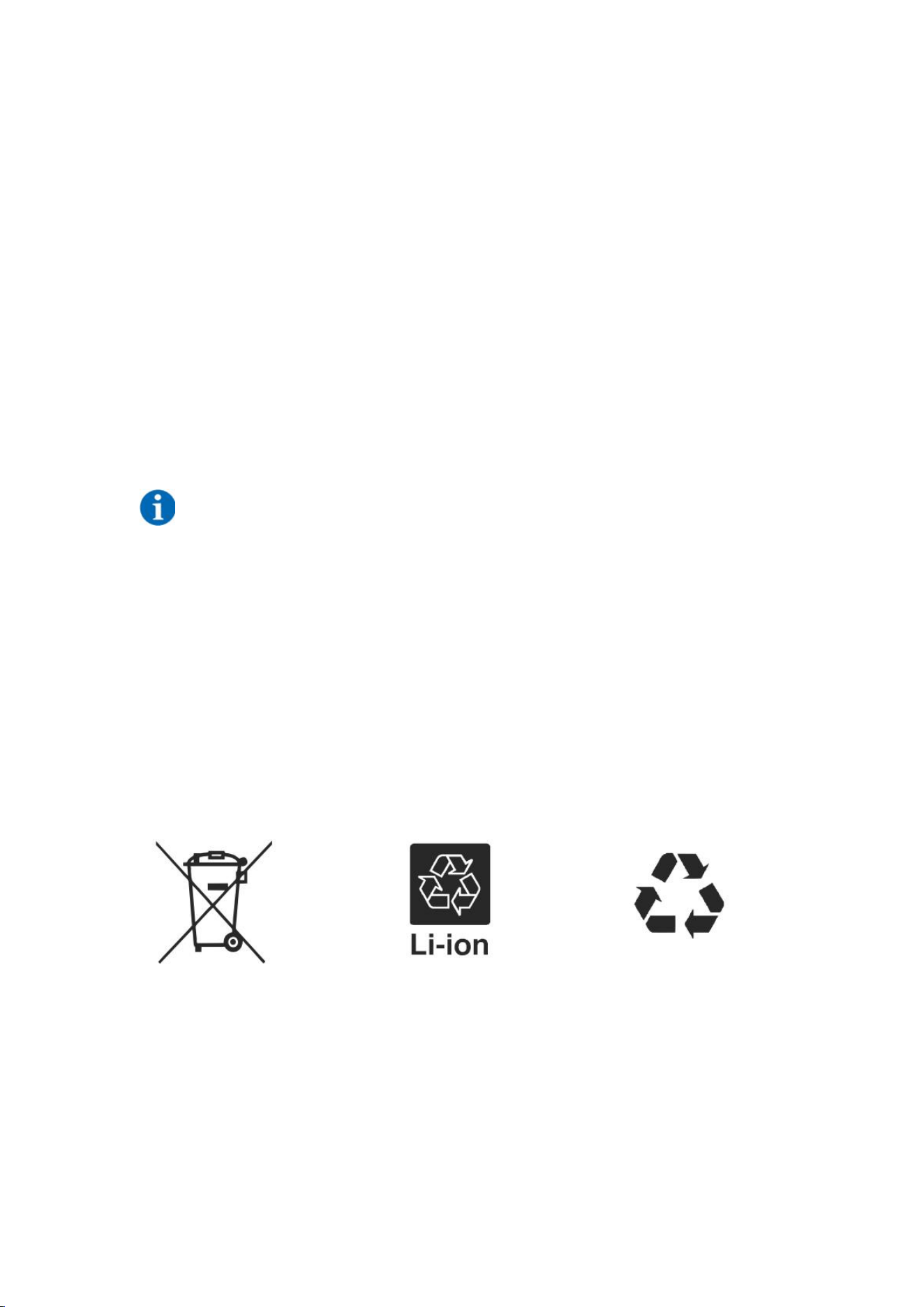
Attention:
1. Do not dispose of batteries and rechargeable batteries as domestic waste!
You are legally obliged to return used batteries and rechargeable batteries.
2. Waste batteries may contain pollutants that can damage the environment or your health if
imProperly stored or handled.
3. Batteries also contain iron, lithium and other important raw materials, which can be recycled.
For more information, please visit http://www.deyeess.com. Do not dispose of batteries as
household waste!

56
11. Legal notice
Installation and Operation Manual for BOS-G Pro
Last revision: 12/2023
Subject to technical changes.
Deye ESS Technology Co., Ltd
Made in China
Legal Statement
The information contained in the document is the Property of Deye ESS Technology Co., Ltd. D
All information shall not be published in whole or in part without the written permission of Deye