A5P | 01
2500950
Please read all instructions carefully before use and
retain for future reference.
CAUTION Do not immerse in water.
Do not cover.
Do not use outdoors.
Disconnect appliance from mains before cleaning,
maintenance or after a thermal cut out event.
Please read all instructions carefully before use and
retain for future reference.
INTENDED USE Only operate the appliance for its
intended purpose and within the parameters specied
in this manual.
This appliance is for domestic use only. Do not use
outdoors or on wet surfaces.
This appliance is not intended for use by persons with
reduced physical, sensory or mental capabilities, or
lack of experience and knowledge, unless supervised or
given appropriate instruction concerning the product’s
use by a person responsible for their safety.
The appliance is not intended to be operated by means
of an external timer or separate remote-control system.
GENERAL SAFETY Do not allow to be used as a toy.
Children should be supervised to ensure they do not
play with the appliance.
If the appliance is not functioning properly, has been
dropped, damaged, left outdoors, or immersed in liquid,
do not use, contact DOMU Brands Customer Services.
Do not use the appliance if any parts appear to be faulty,
missing or damaged.
Ensure all parts are securely attached as instructed by
this instruction manual before use.
OVERLOAD PROTECTION
In the event of a power loss, to protect the compressor
there is a 3 Min delay until the compressor will restart.
Caution Risk of re R290
Appliance shall be installed, operated and stored in a
room with a oor area larger than 9m
2
Local Air
Conditioner

A5P | 01
CABLES AND PLUGS Check to ensure your electricity
supply matches that shown on the rating plate. This
product should only be used as rated. Preferably, the
socket outlet should be protected by a Residual Current
Device RCD (UK/EU) Ground Fault Indicator (US).
Do not use with a damaged cable or plug. If the supply
cable is damaged, it must be replaced by a qualied
engineer or authorised service agent in order to avoid a
hazard. The use of an extension cable is not recom-
mended.
Do not handle the plug or appliance with wet hands.
Keep the cable away from heated surfaces.
Do not let the cable hang over the edge of the table or
countertop where it could be pulled on inadvertently by
children or pets.
Do not pull the cable around sharp edges or corners.
Do not leave unattended when plugged in. Unplug from
outlet when not in use.
Turn o all controls before unplugging.
Do not unplug by pulling on the cable. To unplug, grasp
the plug, not the cable.
Always unplug before performing user maintenance,
connecting or disconnecting attachments, or changing
accessories.
Ensure the cable is stored safely to prevent hazards.
RISK OF PERSONAL INJURY.
Always locate your appliance away from the edge of
any worktop, on a rm, at, heat-resistant surface with
sucient space around all sides.
Ensure that the appliance is at room temperature before
operating.
The appliance is not intended to be operated by means
of an external timer or separate remote-control system.
When using for the rst time, your appliance may give
o a ‘new’ smell. This will dissipate after a few uses.
Keep hair, loose clothing, ngers, and all parts of body
away from openings and moving parts.
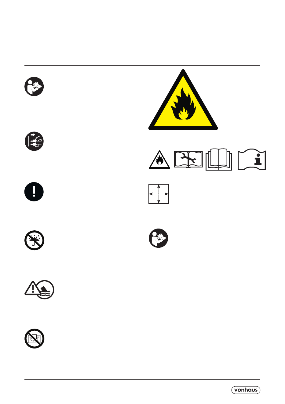
1. Control Panel
2. Signal Receiver
3. Cold Air Outlet
4. Remote Control
5. Transportation Handle
6. Evaporator Air Intake
7. Air Outlet Hose
8. Primary Drain Port.
WINDOW KIT
9. Connector of Air Exhaust Duct
10. Window Exhaust Adapter.
11. Air Exhaust Duct.
12. Bae Plates.
13. Wingnut /Washer/Bolt.
Do not insert any object into openings or cover the
appliance.
Do not obstruct the air inlets/outlets of the appliance.
Do not use in the following locations:-
- Next to a source of re
- An area where oil is likely to splash
- An area exposed to direct sunlight
- An area where water is likely to splash
- Laundry or wet rooms where the humidity is higher
than 85% RH.
- Near a bath, shower or a swimming pool
- In a greenhouse
- An area where ammable gases or liquids are present
Do not dry laundry above the unit to prevent water
entering the Air Conditioner.
Place laundry at least 1 meter away from the Air Con-
ditioner.
Do not lift or move the appliance whilst in use.
Do not leave the appliance unattended when plugged
in. Unplug from outlet when not in use, and before per-
forming user maintenance, connecting or disconnecting
attachments or changing accessories.
Do not operate continuously for periods longer than
those marked on the product or indicated in the
instructions.
Do not lubricate any parts, or carry out any maintenance
or repair work other than that shown in this manual, or
as advised by the DOMU Brands Customer Services.
Use only as described in this manual and do not exceed
maximum capacity.
Use only DOMU Brands recommended attachments.
Failure to follow these instructions will invalidate any
warranty.
Energy/Safety protection
Do not cover or restrict the air ow of the inlet/outlet
grills.
For maximum performance ensure the minimum dis-
tance from walls or objects is be 20cm.
Keep lters and grills clean.
When in use do not open windows or doors. Place the
unit of a hard/at surface.
TECHNICAL SPECIFICATION
Rated Voltage 220-240V
Rated Power 950W
Rated Frequency 50Hz
COMPONENT LIST / LISTE DES COMPOSANTS / KOMPONENTENLISTE /
A5P | 01
CONTENTS / CONTENU / INHALT / CONTENIDOS / CONTENUTO / CONTENIDO
1
10
11
12
13
2
3
4
5
6
7
8
9
A5P | 01
CONTENTS / CONTENU / INHALT / CONTENIDOS / CONTENUTO / CONTENIDO
CONTENTS / CONTENU / INHALT / CONTENIDOS / CONTENUTO / CONTENIDO
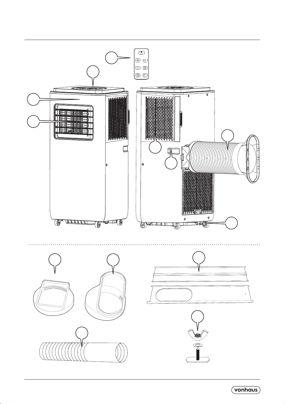
POWER BUTTON:
Once the Unit has been connected to a suitable mains outlet, press this key to turn the Air Conditioner ON and OFF.
When powered ON, the screen will display the room temperature and begin to operate in Automatic Mode.
SPEED BUTTON:
Press the Speed button once to select low speed
. Press a second time to select the high speed .
ADJUST TEMPERATURE:
The temperature can be set within a range of 15ºC to 31ºC.
Each press of the + or - button will increase/descrease the temperature by 1ºC.
The unit will display the target temperature for 5 seconds and then display the room temperature.
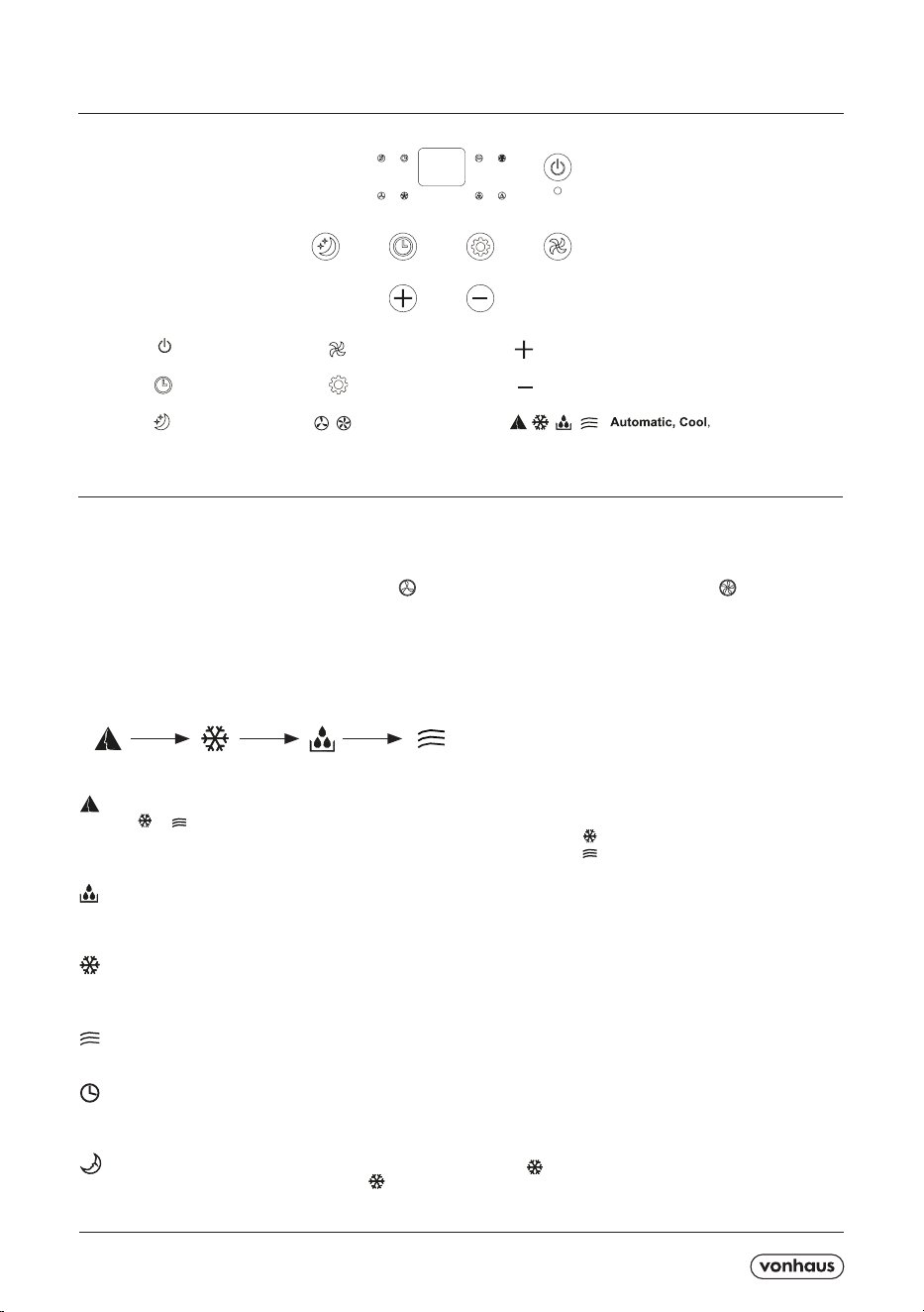
MODE SELECTION:
Press the Mode button to cycle through and select a desired mode shown below -
Automatic, Cool, Dehumidify and fan mode. Please see below the working priciple of each mode.
- 1.Automatic Mode selected, the indoor temperature sensor operates automatically to select the desired opera-
tion with
or .
2. When the room temperature is above 24ºC, the unit will automatically select
.
3. When the room temperature is below 24ºC, the unit will automatically select
.
- 1. The up centrifugal fan will run at low speed, and the speed cannot be adjusted.
2. The compressor and down centrifugal fan will stop after running for 8 mins. It will begin to run again after 6 mins.
3. The Unit adopts constant temperature dehumidifying mode, and the adjustment of temperature is not aected.
- 1. When the room temperature is higher than set temperature, the compressor starts to run.
2. When the room temperature is lower than set temperature, the compressor will stop and the upper fan will operate
at the original speed.
- 1. The fan runs at set speed, and the compressor does not run.
2. the adjustment of temperature is not aected.
- 1. Press ‘Timer’ button to set automatic o time while the unit is running.
2. Press ‘Timer’ button to set automatic on time while the unit is running.
3. The time can be adjusted within a range of 1 hour to 24 hours. Press the + or - button to increase/decrease the
time by 1 hour.
- 1. Sleep mode is only eective when the unit is under cool mode .
2. Press the sleep button when in cool mode , the unit will then work under sleep mode and the up centrifugal fan
will automatically turn to low speed. The set temprature will increase 1ºC after 1 hour and increase 2ºC after 2 hours.
After 6 hours, the unit will stop running.
Timer/Temperature up button
Timer/Temperature down button
Timer button
Sleep button
Mode button
Speed button
Power button
low、high Fan speed
Dehumidify and Fan mode
A5P | 01
CONTENTS / CONTENU / INHALT / CONTENIDOS / CONTENUTO / CONTENIDO
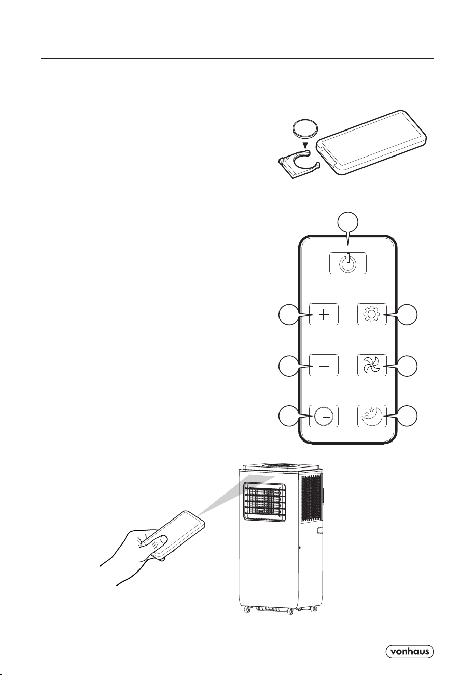
INSTALLING THE BATTERY -
1. Open the back cover and take o the isolating lm on the battery.
2. Insert the battery into the slot (with anode and cathode in the right directions.
3. Slide the cover back into the base of the remote control.
IMPORTANT!
1. The anode and cathode of the battery must be corresponding to the
signs of ‘+ and -’ on the remote control.
2. Do not use new battery cells together with run-down cells.
3. When not in use for a long time, remove the battery.
4. To prevent environmental pollution, take out the used battery
and dispose of safely and appropriately.
REMOTE CONTROL OPERATION -
1. Power Button. Once the unit is connected to the mains outlet,
press once to switch the unit on. Press a second time to switch o.
2. Mode selection Button. Press to cycle through
Automatic, Cool, Dehumidify and fan mode.
3. Fan Button. Press to select either Low or High fan mode.
4. Sleep Mode Button. Press to select or cancel the sleep mode.
5. Timer Button. Used to set the automatic o or automatic on.
6. Decrease Button. Decrease the time or temperatures set.
7. Increase Button. Increase the time or temperature set.
To use, simply aim the Remote Control towards the
signal receptor at the top of the Main Unit. The Remote will only work
within a distance of 5m (16.4ft) from the Air Conditioner Unit.
1
27
36
45
A5P | 01
CONTENTS / CONTENU / INHALT / CONTENIDOS / CONTENUTO / CONTENI-
DO
CONTENTS / CONTENU / INHALT / CON-
TENIDOS / CONTENUTO / CONTENIDO
CONTENTS / CONTENU
/ INHALT / CONTENI-
DOS / CONTENUTO /
CONTENIDO
13
Fig2
A
B
B
Fig1
Fig3
CONTENTS / CONTENU / INHALT / CON-
TENIDOS / CONTENUTO / CONTENIDO
A5P | 01
CONTENTS / CONTENU / INHALT / CONTENIDOS / CONTENUTO / CONTENI-
CONTENTS / CONTENU / INHALT / CONTENIDOS / CONTENUTO / CONTENI-
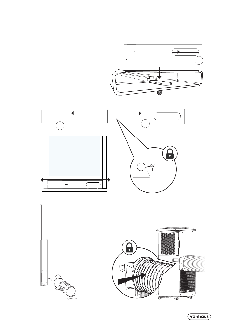
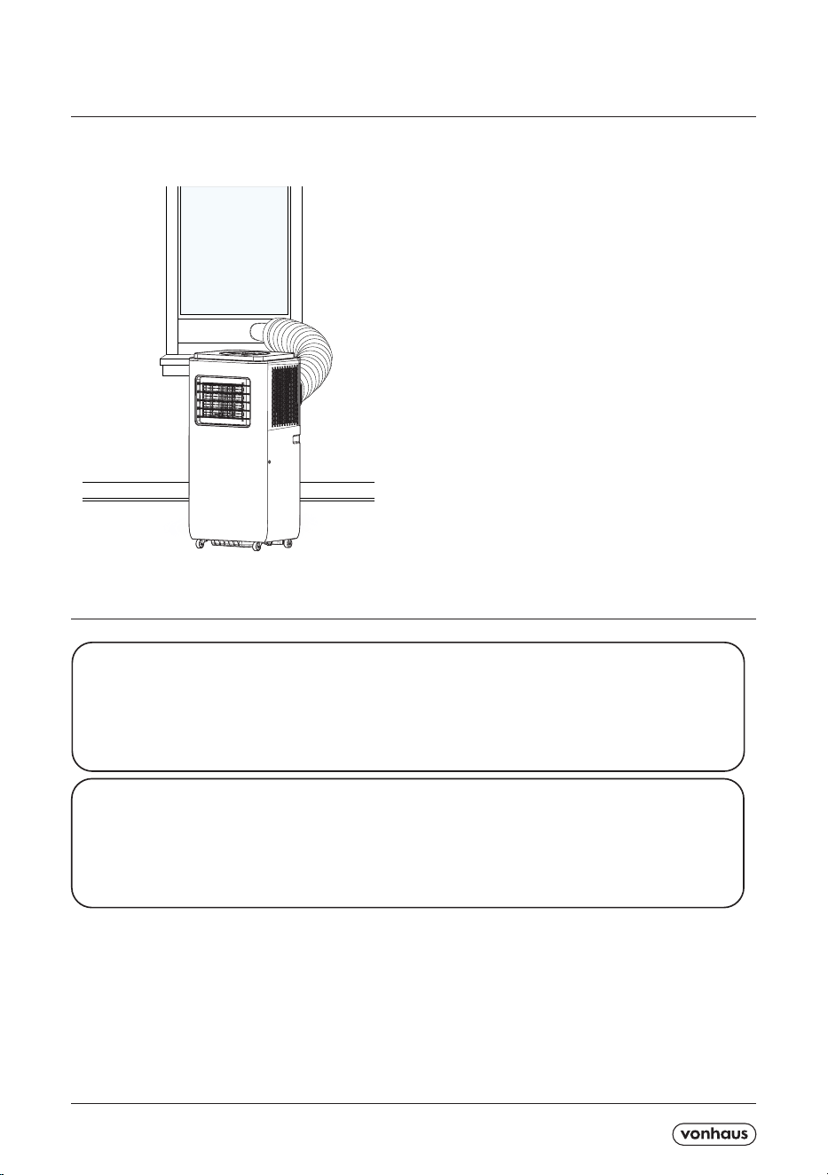
Position the Air Conditioner close to a window.
When choosing where to position the Air Conditioner,
ensure that there is at least 50cm of space around the
unit.
Open the window slightly to allow enough space for the
Slide Bar to t. For larger windows use the Extender to
adjust the size of the Slide Bar.
A poorly positioned Air Conditioner will have little eect
and will not work to it’s full potential. Ensure when in
use all doors and windows are closed.
Do not force the castor wheels to move over carpet, or
attempt to move the unit when it is in operation this may
cause the tank to tip over and water to spill causing a
hazardous environment.
CAUTION: Do not allow the Exhaust Hose to bend
sharply. The Hose should be curved to allow smooth
ow of air.
NOTE: The full length of the Exhaust Hose is 150cm.
Keep the hose as short and as straight as possible for
the best results.
The self-evaporating system uses the collected water to cool the condenser coils for ecient performance.
There is no need to empty the drainage tank in cooling operation except when in drying mode and high
humidity conditions.
The condensates water evaporates at the condenser and is drained through the exhaust hose.
For continuous operation or unattended operating in drying mode, please connect a drain hose to the unit.
Condensed water can be automatically ow into a bucket or drain by gravity. E4 will be displayed on the screen to
remind you to drain the water.
The protective device may trip and stop the appliance in the cases listed below -
COOLING - Indoor air temperature is over 43ºC or Room temperature is below 15ºC.
DEHUMIDIFIYING - Room temperature is below 15ºC.
If the Air Conditioner runs in ‘Cooling or Dry’ mode with doors or windows opened for a long period of time when
relative humidity if above 80%, dew may drip down from the outlet.
1 - The protective device will work in the following cases -
* Restarting the Unit at once after operation stops or changing mode during operation, you need to wait 3 minutes.
2 * If the plug is taken out, when you restart the appliance, it will return to the original mode,
TIMER ON and TIMER OFF must be set again.
A5P | 01
CONTENTS / CONTENU / INHALT / CONTENIDOS / CONTENUTO / CONTENIDO
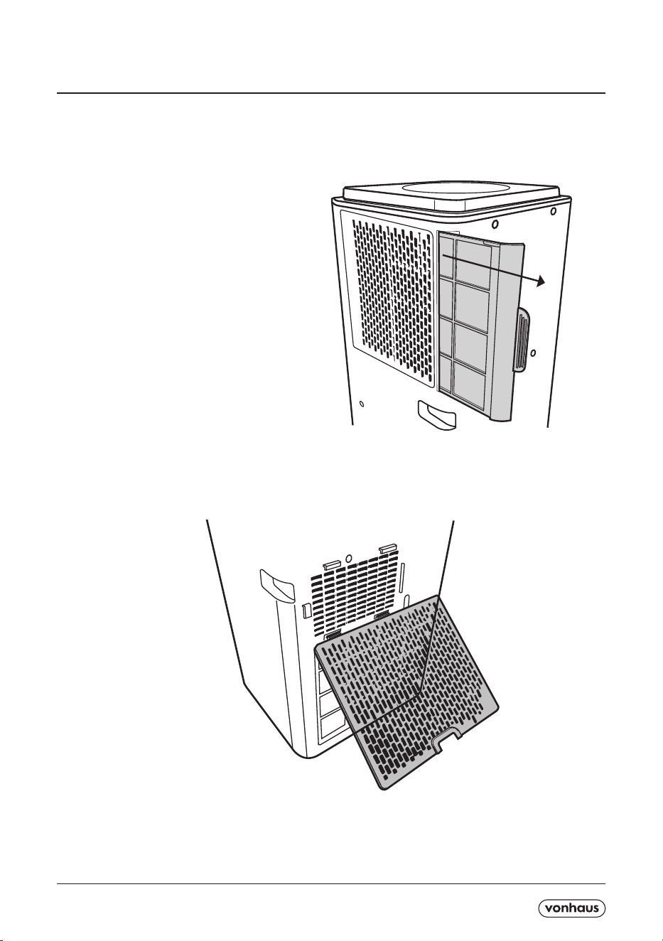
CAUTION: Before cleaning please ensure that the
machine is powered o and unplugged from the main
socket.
To clean, remove both upper and lower lters by gently
pulling until they unclip
Using a soft bristle brush or vacuum cleaner, gently
brush away any dust or dirt. If the lter is heavily dirty,
wash with warm soapy water and leave to dry
completely for 24hrs before re-inserting.
CAUTION: Do not use a wet lter. This can cause
damage to the unit or even an electrical shock.
Clean the exterior using a damp cloth
To clean the Air Outlet use a soft bristle brush.
CAUTION: Do not attempt to access internal parts for
cleaning or maintenance.

A5P | 01
CONTENTS / CONTENU / INHALT / CONTENIDOS / CONTENUTO / CONTENIDO
1.Checks to the area
Prior to beginning work on systems containing
ammable refrigerants, safety checks are necessary to
ensure that the risk of ignition is minimized for repair
to the refrigerating system, the following precautions
shall be complied with prior to conducting work on the
system.
Work procedure
Work shall be undertaken under a controlled procedure
so as to minimize the risk of a ammable gas or vapour
being present while the work is being performed.
2.General work area
All maintenance sta and others working in the local
area shall be instructed on the nature of work being
carried out. Work in conned spaces shall be avoided.
The area around the workspace shall be sectioned o.
Ensure that the conditions within the area have been
made safe by control of ammable material.
3.Checking for presence of refrigerant
The area shall be checked with an appropriate
refrigerant detector prior to and during work, to ensure
the technician is aware of potentially ammable
atmospheres. Ensure that the leak detection equipment
being used is suitable for use with ammable refrigerant,
i.e. non sparking, adequately sealed or intrinsically safe.
4.Presence of re extinguisher
If any hot work is to be conducted on the refrigeration
equipment or any associated parts, appropriate re
extinguishing equipment shall be available to hand.
Have a dry powder or CO2 re extinguisher adjacent to
the charging area.
5.No ignition sources
No person carrying out work in relation to a refrigerant
system which involves exposing any pipe work that
contains or has contained ammable refrigerant shall
use any sources of ignition in such a manner that it
may lead to the risk of re or explosion. All possible
ignition sources, including cigarette smoking, should
be kept suciently far away from the site of installation,
repairing, removing and disposal, during which
ammable refrigerant can possibly be released to the
surrounding space. Prior to work taking place, the area
around the equipment is to be surveyed to make sure
that there are no ammable hazards or ignition risks.”No
Smoking”signs shall be displayed.
6.Ventilated area
Ensure that the area is in the open or that it is
adequately ventilated before breaking into the system
or conducting any hot wok. A degree of ventilation shall
continue during the period that the work is carried out.
The ventilation should safely disperse any released
refrigerant and preferably expel it externally into the
atmosphere.
7.Checks to the refrigeration equipment
Where electrical components are being changed,
they shall be t for the purpose and to the correct
specication. At all times the manufacturer’s
maintenance and service guidelines shall be followed.
If in doubt consult the manufacturer’s technical
department for assistance.
The following checks shall be applied to installations
using ammable refrigerants:
- the charge size in accordance with the room size
within which the refrigerant containing parts are
installed;
- the ventilation machinery and outlets are operating
adequately and are not obstructed
8.Checks to electrical devices
Repair and maintenance to electrical components shall
include initial safety checks and components inspection
procedures. If a fault exists that could compromise
safety, then no electrical supply shall be connected to
the circuit until it is satisfactorily dealt with. If the fault
cannot be corrected immediately but it is necessary to
continue operation, an adequate temporary solution
shall be used. This shall be reported to the owner of the
equipment so all parties are advised.
Initial safety checks shall include:
-that capacitors are discharged: this shall be done in a
safe manner to avoid possibility of sparking;
-that there no live electrical components and wiring
are exposed while charging, recovering or purging the
system;
-that there is continuity of earth bonding
9.Repairs to sealed components
During repairs to sealed components, all electrical
supplies shall be disconnected from the equipment
being worked upon prior to any removal of sealed
covers, etc.
If it is absolutely necessary to have an electrical supply
to equipment during servicing, then a permanently
operating form of leak detection shall be located at the
most critical point to warn of a potentially hazardous
situation.
Particular attention shall be paid to the following to
ensure that by working on electrical components, the
casing is not altered in such a way that the level of
protection is aected. This shall include damage to
cables, excessive number of connections, terminals
not made to original specication, damage to seals,
incorrect tting of glands, etc.
Ensure that apparatus is mounted securely.
Ensure that seals or sealing materials have not
degraded such that they no longer serve the purpose
of preventing the ingress of ammable atmospheres,
Replacement parts shall be in accordance with the
manufacturer’s specications.
NOTE: The use of silicon sealant may inhibit the
eectiveness of some types of leak detection
equipment. Intrinsically safe components do not have to
be isolated prior to working on them.
10.Repair to intrinsically safe components
Do not apply any permanent inductive or capacitance
loads to the circuit without ensuring that this will not
exceed the permissible voltage and current permitted
for the equipment in use.
Intrinsically components are the only types that can be
worked on while live in the presence of a ammable
atmosphere. The test apparatus shall be at the correct
rating.
Replace components only with parts specied by
manufacturer. Other parts may result in the ignition of
refrigerant in the atmosphere from a leak.
11.Cabling
Check that cabling will not be subject to wear, corrosion,
excessive pressure, vibration, sharp edges or any other
adverse environmental eects. The check shall also take
into account the eects of aging or continual vibration
from sources such as compressors or fans.
12.Leakage detection for ammable refrigerants .

A5P | 01
CONTENTS / CONTENU / INHALT / CONTENIDOS / CONTENUTO / CONTENIDO
Under no circumstances shall potential sources of
ignition be used in the searching for or detection of
refrigerant leaks. A halide torch (or any other detector
using a naked ame) shall not be used.
13.Leak detection methods
The following leak detection methods are acceptable for
systems containing ammable refrigerant.
Electronic leak detectors shall be used to detect
ammable refrigerants, but the sensitivity may not
be adequate, or may need recalibration (Detection
equipment shall be calibrated in a refrigerant-free area.)
Ensure that detector is not a potential source of ignition
and is suitable for the refrigerant used.
Leak detection uids are suitable for use with most
refrigerants but the use of detergents containing chlorine
shall be avoided as the chlorine may react with the
refrigerant and corrode the copper pipe-work.
If a leak is suspected, all naked ames shall be
removed/extinguished.
If a leak of refrigerant is found which requires brazing,
all of the refrigerant shall be recovered from the system.
Oxygen free nitrogen (OFN) shall then be purged through
the system both before and during the brazing process.
14.Removal and evacuation.
When breaking into the refrigerant circuit to make
repairs-or for any other purpose-conventional
procedures shall be used. However, it is important
that best practice is followed since Flammability is a
consideration. The following procedure shall be adhered
to:
Remove refrigerant;
Purge the circuit with inert gas;
Evacuate;
Purge again with inert gas;
Open the circuit by cutting or brazing.
The refrigerant charge shall be recovered into the correct
recovery cylinders. The system shall be”ushed”with
OFN to render the unit safe. This process may need to
be repeated several times. Compressed air or oxygen
shall not be used for this task.
Flushing shall be achieved by breaking the vacuum
in the system with OFN and continuing to ll until
the working pressure is achieved, then venting to
atmosphere, and nally pulling down to a vacuum. This
process shall be repeated until no refrigerant is within
the system. When the nal OFN charge is used, the
system shall be vented down to atmospheric pressure
to enable work to take place.
This operation is absolutely vital if brazing operations on
the pipework are to take place. Ensure that the outlet for
the vacuum pump is not close to any ignition sources
and there is ventilation available.
15.Refrigerant Charging procedures.
In addition to conventional charging procedures, the
following requirements shall be followed.
-Ensure that contamination of dierent refrigerants
does not occur when using charging equipment. Hoses
or lines shall be as short as possible to minimize the
amount of refrigerant contained in them.
-Cylinders shall be kept upright.
-Ensure that the refrigeration system is earthed prior to
charging the system with refrigerant.
-Label the system when charging is complete (if not
already).
-Extreme care shall be taken not to overll the
refrigeration system.
Prior to recharging the system, it shall be pressure
tested with OFN. The system shall be leak tested on
completion of charging but prior commissioning. A
follow up leak test shall be carried out prior to leaving
the site.
to original specication, damage to seals, incorrect.
16.Decommissioning
Before carrying out this procedure, it is essential that
technician is completely familiar with the equipment
and all its detail. It is recommended good practice that
all refrigerants are recovered safely. Prior to the task
being carried out, an oil and refrigerant sample shall
be taken in case analysis is required prior to reuse of
reclaimed refrigerant. It is essential that electrical power
is available before the task is commenced.
Become familiar with the equipment and its operation.
b) Isolate system electrically.
c) Before attempting the procedure ensure that:
mechanical handling equipment is available, if repaired,
for handling refrigerant cylinders; all personal protective
equipment is available and being used correctly;
the recovery process is supervised at all times by a
competent person; recovery equipment and cylinders
conform to the appropriate standards.
d) Pump down refrigerant system, if possible.
e) if a vacuum is not possible, make a manifold so that
refrigerant can be removed from various parts of the
system.
f) Make sure that cylinder is situated on the scales
before recovery takes place.
g) Start the recovery machine and operate in
accordance with manufacturer’s instructions.
h) Do not overll cylinders (No more than 80% volume
liquid charge).
i) Do not exceed the maximum working pressure of the
cylinder, even temporarily.
j) When the cylinders have been lled correctly and the
process completed, make sure that the cylinders and
the equipment are removed from site promptly and all
isolation valves on the equipment are closed o.
k) Recovered refrigerant shall not be charged into
another refrigeration system unless it has been cleaned
and checked.
17.Labelling
Equipment shall be labelled stating that it has been
decommissioned and emptied of refrigerant. The label
shall be dated and signed. Ensure that there are labels
on the equipment stating the equipment contains
ammable refrigerant.
18.Recovery
When removing refrigerant from a system, either for
servicing or decommissioning, it is recommended good
practice that all refrigerants are removed safely.
When transferring refrigerant into cylinders, ensure
that only appropriate refrigerant recovery cylinders are
employed. Ensure that the correct number of cylinders
for holding the total system charge are available. All
cylinders to be used are designed for the recovered
refrigerant and labelled for that refrigerant(i.e.special
cylinders for the recovery of refrigerant). Cylinders shall
be complete with pressure relief value and associated
shut-o values in good working order. Empty recovery
cylinders are evacuated and, if possible, cooled before
recovery occurs.
The recovery equipment shall be in good working order
with a set of instructions concerning the equipment
that is at hand and shall be suitable for the recovery of
ammable refrigerants.
In addition, a set of calibrated weighing scales shall
be available and in good work order. Hoses shall be
complete with leak-free disconnect couplings and in
good condition.

A5P | 01
CONTENTS / CONTENU / INHALT / CONTENIDOS / CONTENUTO / CONTENIDO
Before using the recovery machine, check that it
is in satisfactory working order, has been properly
maintained and that any associated electrical
components are sealed to prevent ignition in the event
of a refrigerant release. Consult manufacturer if in doubt.
The recovered refrigerant shall be returned to the
refrigerant supplier in the correct recovery cylinder,
and the relevant Waste Transfer Note arranged. Do not
mix refrigerants in recovery units and especially not in
cylinders.
If compressors or compressor oils are to be removed,
ensure that they have been evacuated to an acceptable
level to make certain that ammable refrigerant does
not remain within the lubricant. The evacuation process
shall be carried out prior to returning the compressor to
the suppliers. Only electric heating to the compressor
body shall be employed to accelerate this process.
When oil is drained from a system, it shall be carried
out safely.
19.Transport of equipment containing ammable
refrigerants.
Determined by local regulations.
20.Discarded appliances supplies ammable
refrigerants.
See National Regulations.
21.Storage package (unsold) equipment
Storage package protection should be constructed such
that mechanical damage to the equipment inside the
package will not cause a leak of the refrigerant charge.
The maximum number of pieces of equipment permitted
to be stored together will be determined by local
regulations.
A5P | 01
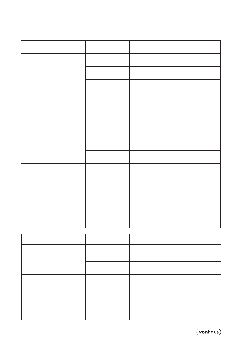
Symptom Inspection Solution
The unit is not operating
Check the power
connection in securely.
Insert the power cord securely into the wall
Outlet.
Check if the water level
indicator lights up?
Empty the drain pan by remove the rubber plug.
Check the room
temperature.
The range of operating temperature is 5-35℃.
The unit works with reduced
capacity
Check the air filter
for dirt.
Clean the air filter as necessary.
Check if the air duct is
blocked.
To clear the obstacle.
Check if the room door
or window is open.
Keep the door and windows closed.
Check if the desired
operating mode is
selected and the tem-
perature is properly set.
Set the mode and temperature at proper set-point
according the manual.
The exhaust hose is
detached.
Make sure the exhaust hose is securely attached.
Water leakage Overflow while moving
the unit.
Empty the water tank before transport.
Check if the drain hose
is kinked or bends.
Straighten the hose to avoid a trap existing.
Excessive noise Check if the unit is
securely positioned.
Place the unit on horizontal and firm ground.
Check if any loose,
vibrating parts.
Secure and tight the parts.
Noise sounds like
water flowing.
Noise comes from flowing refrigerant. This is
normal.
CONTENTS / CONTENU / INHALT / CONTENIDOS / CONTENUTO / CONTENIDO
Symptom Inspection Solution
No cold air under COOLING mode Room temp lower than
set temp.
This is completely normal, the Unit will
automatically switch while thee room temp is
higher than the set temp.
Unit in anti-frost
protection
The Unit will automatically switch after the
anti-frost protection is over.
LED displays failure code ‘E2’ Room temp sensor has
failed or damaged
Replace the room
temperature sensor.
LED displays failure code ‘E3’ The evaporator coil
pipe sensor has failed
or damaged.
Have the evaporator coil pipe sensor replaced.
LED displays failure code ‘E4’ Water full warning. Drain the excess water from the drainage port
using a drainage hose or large container.

A5P | 01
CONTENTS / CONTENU / INHALT / CONTENIDOS / CONTENUTO / CONTENIDO

A5P | 01
EN
DISPOSAL INFORMATION Please recycle where
facilities exist. Check with your local authority for
recycling advice.
CUSTOMER SERVICE If you are having diculty using
this product and require support, please contact
WARRANTY To register your product and nd out if you
qualify for a free extended warranty please go to
www.vonhaus.com/warranty.
Please retain a proof of purchase receipt or statement
as proof of the purchase date. The warranty only applies
if the product is used solely in the manner indicated
in the warnings page of this manual, and all other
instructions have been followed accurately. Any abuse
of the product or the manner in which it is used will
invalidate the warranty. Returned goods will not be ac-
cepted unless re-packaged in its original packaging and
accompanied by a relevant and completed returns form.
This does not aect your statutory rights. No rights
are given under this warranty to a person acquiring the
appliance second-hand or for commercial or communal
use.
COPYRIGHT All material in this instruction manual are
copyrighted by DOMU Brands.Any unauthorised use
may violate worldwide copyright, trademark, and other
laws.
THANK YOU
Thank you for purchasing your product/appliance.
Should you require further assistance with your
purchase, you can contact us at
VonHaus is a registered trademark of DOMU Brands Ltd.
Made in China for DOMU Brands. M24 2RW.
C
