SFTRACE LTV SELF-REGULATING HEATING CABLES cCSAus
THERMAL MANAGEMENT SOLUTIONS | 1/11 | WUHU XUHUI ELECTRIC NEW MATERIAL CO., LTD
Specifications
Area classification
3LTV, 5 LTV, 8 LTV, 10 LTV, 12 LTV: all can use for pipe tracing
5 LTV, 8 LTV: roof and gutter de-icing
Supply voltage
120V
240V
Maximum maintain or
continuous exposure
temperature (power on/off)
65℃
Maximum intermittent
exposure
temperature (power on/off)
85℃
Maximum cumulative exposure 1000 hours
Minimum installation
temperature
-20℃
Minimum bend radius
at 20℃: 15mm
at -20
℃
: 35mm
Product
LTV
Thickness (mm)
6
Width (mm)
13
Ground-fault protection
To minimize the danger of fire from sustained electrical arcing if the heating cable is damaged or
improperly installed, and to comply with the requirements of Xuhui, agency certifications, and
national electrical codes, 30-mA equipment or 5-mA personnel ground-fault protection must be used
on each LTV heating cable branch circuit. Arcing may not be stopped by conventional circuit
protection.
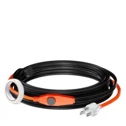
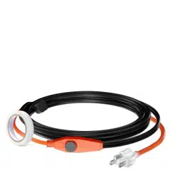
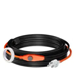
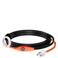
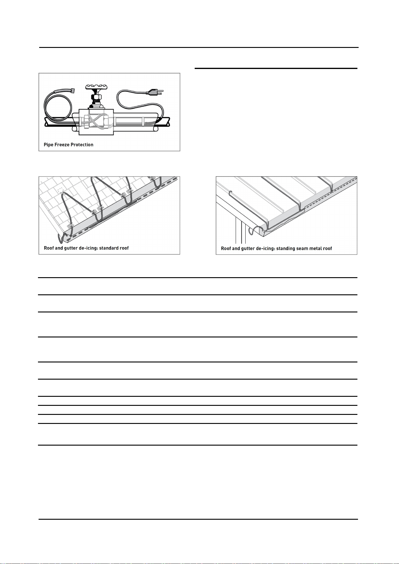
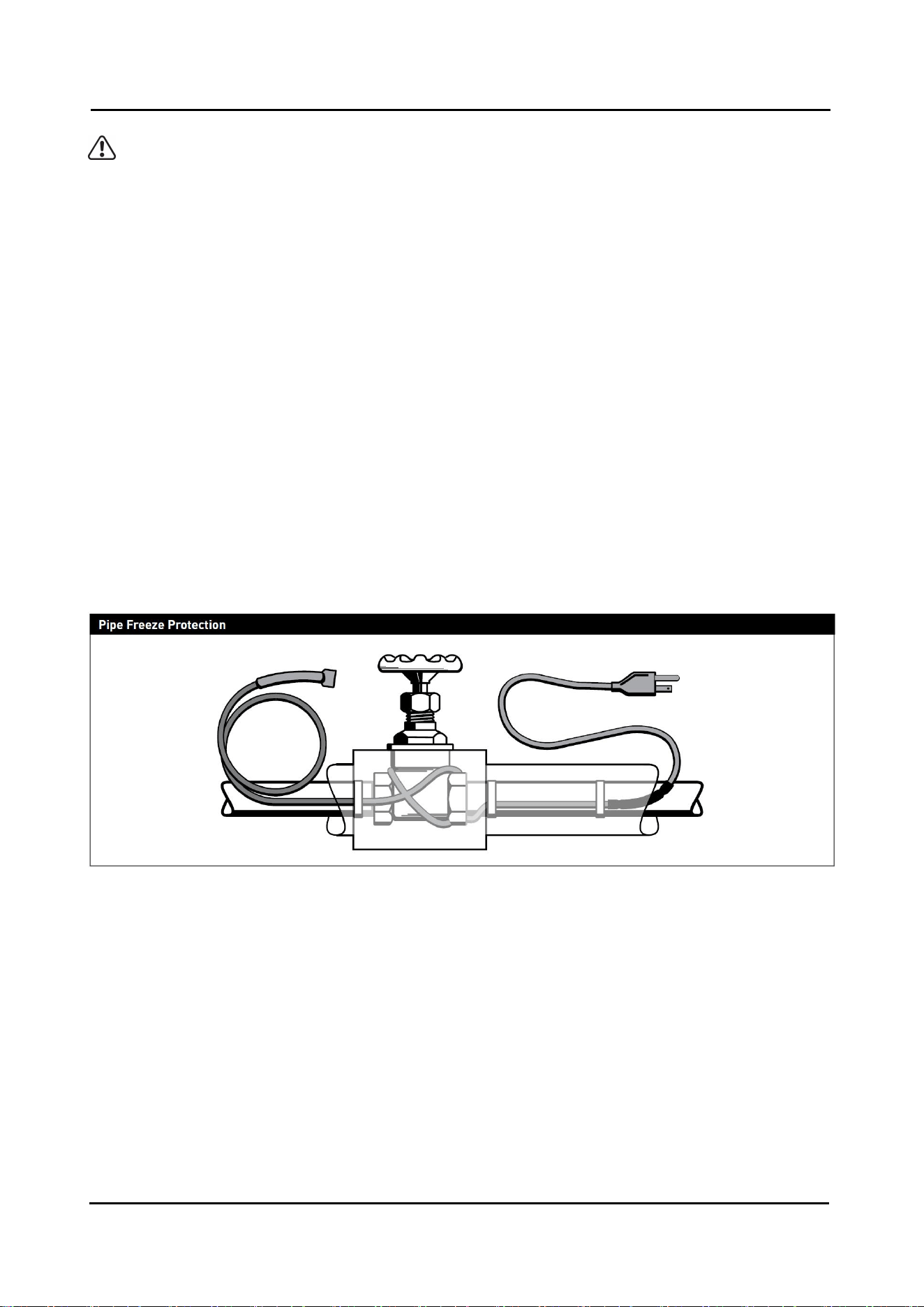
Description
The LTV pre-assembled self-regulating heating
cables are designed for residential and commercial
metal and plastic pipe freeze protection and roof and
gutter deicing applications.
The LTV pre-assembled cables are available in 1-100
feet lengths for 3LTV and 5LTV, in 1-50 feet length for
8LTV, 10LTV and 12LTV, each comes assembled
with a power cord with or without a plug.
The LTV pre-assembled cables more than 100/50
feet lengths are available comes assembled with a
power cord for terminating in a listed standard
junction box.
SFTRACE LTV SELF-REGULATING HEATING CABLES cCSAus
THERMAL MANAGEMENT SOLUTIONS | 2/11 | WUHU XUHUI ELECTRIC NEW MATERIAL CO., LTD
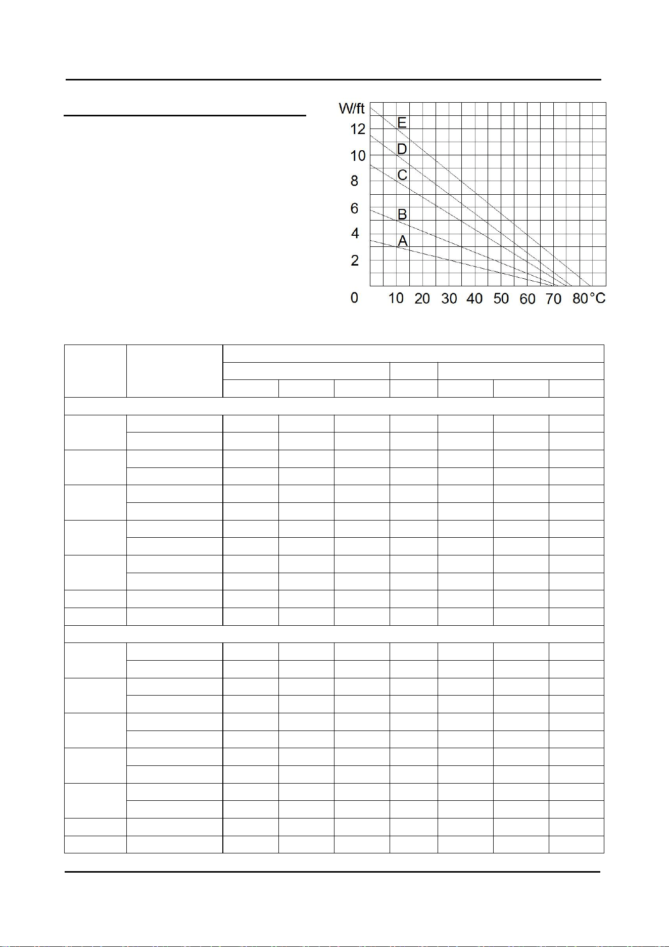
Thermal output rating
Nominal power output at 120Vac
(LTV1) and 240Vac (LTV2)
insulated on steel pipes
W/ft
@ 10℃
A
3LTV1, 3LTV2
3
B
5LTV1, 5LTV2
5
C
8LTV1, 8LTV2
8
D
10LTV1, 10LTV2
10
E
12LTV1, 12LTV2
12
Heating cable sets 5LTV (8w/ft@0ºC) and 8LTV
(15w/ft@0ºC) are covered for roof and gutter
de-icing.
Pipe temperature
Maximum circuit lengths (ft) based on circuit breaker sizes
Products
Ambient
temperature
at start-up
Maximum circuit length (in feet) per circuit breaker
120V
240V
15A
20A
25A
15A
20A
25A
LTV with 16awg conductors
3LTV
50℉ (10℃)
330
330
330
660
660
660
0℉ (-20℃)
200
250
300
400
500
600
5LTV
50℉ (10℃)
230
270
270
460
540
540
0℉ (-20℃)
140
190
240
280
380
480
8LTV
50℉ (10℃)
150
180
200
300
360
400
0℉ (-20℃)
100
130
160
200
260
320
10LTV
50℉ (10℃)
120
140
160
240
280
320
0℉ (-20℃)
80
110
140
160
220
280
12LTV
50℉ (10℃)
100
120
140
200
240
280
0℉ (-20℃)
70
90
110
140
180
220
8w/ft
32℉ (0℃)
100
120
140
200
240
280
15w/ft
32℉ (0℃)
60
75
90
120
150
180
LTV with 18awg conductors
3LTV
50℉ (10℃)
250
250
250
500
500
500
0℉ (-20℃)
200
200
200
400
400
400
5LTV
50℉ (10℃)
180
180
180
360
360
360
0℉ (-20℃)
140
160
160
280
320
320
8LTV
50℉ (10℃)
150
150
150
300
300
300
0℉ (-20℃)
100
130
130
200
260
260
10LTV
50℉ (10℃)
120
130
130
240
260
260
0℉ (-20℃)
80
110
110
160
220
220
12LTV
50℉ (10℃)
100
110
110
200
220
220
0℉ (-20℃)
70
90
90
140
180
180
8w/ft
32℉ (0℃)
100
120
120
200
240
240
15w/ft
32℉ (0℃)
60
75
90
120
150
180
SFTRACE LTV SELF-REGULATING HEATING CABLES cCSAus
THERMAL MANAGEMENT SOLUTIONS | 3/11 | WUHU XUHUI ELECTRIC NEW MATERIAL CO., LTD
Warning
Fire and Shock Hazard. This product is an electrical device that must be installed correctly to ensure
proper operation and to prevent shock or fire. Read these important warnings and carefully follow all the
installation instructions.
• When used with non-metallic conduit/pipe, the vicat softening temperature of the non-metallic
conduit/pipe shall be greater than 85C.
• To minimize the danger of fire from sustained electrical arcing if the heating cable is damaged or
improperly installed, and to comply with the requirements of Xuhui agency certifications, and national
electrical codes, ground fault equipment protection must be used on each heating cable branch circuit.
Arcing may not be stopped by conventional circuit protection.
• For pipe freeze protection applications, use only fire-resistant insulation materials such as preformed
foam or fiberglass.
• Do not damage the heating cable and power cord or plug. Remove any damaged cables from service
immediately.
• Do not use any wire or metal clamps to attach the cable to the pipe. Use tape (1/2 inch wide to 1 inch
wide) or plastic cable ties.
• Do not install the heating cable underneath any roof covering for roof and gutter de-icing.
• Leave these installation instructions with the user for future reference.
General requirements for pipe freeze protection:
• LTV heating cables may be used on metal and plastic water pipes but not on flexible vinyl tubing (such
as garden hoses).
• LTV heating cables are not intended for use inside any pipes, for freeze protection of liquids other than
water, or for use in classified hazardous locations.
• Install with a minimum of 1/2” fire-resistant, waterproof thermal insulation.
• Never use on any pipes that may exceed 150°F (65°C).
• Do not use an extension cord.
General instructions:
• Install only in accessible locations; do not install behind walls or where the cable would be hidden.
• Do not run the heating cable through walls, ceilings, or floors.
• Connect only to ground-fault protected outlets that have been installed in accordance with all prevailing
SFTRACE LTV SELF-REGULATING HEATING CABLES cCSAus
THERMAL MANAGEMENT SOLUTIONS | 4/11 | WUHU XUHUI ELECTRIC NEW MATERIAL CO., LTD
national and local codes and standards and are protected from rain and other water.
Electrical codes
Articles 422 and 427 of the National Electrical Code (NEC), and Part 1, Section 62 of the Canadian
Electrical Code (CEC), govern the installation of LTV heating cable for pipe freeze protection and must
be followed.
Important: For the Xuhui warranty to be valid, you must comply with all the requirements outlined in
these guidelines.
All thermal and design information provided here is based upon a “standard” installation with heating
cable fastened to an insulated pipe. For any other application or method of installation, consult Xuhui at
86-553-7477605.
Determine which LTV heating cable you need for pipe freeze protection:
Add 1 foot to your pipe length for each valve or spigot on your pipe system.
The lowest outside temperature is 0°F (-18°C), need a minimum of 1/2” thick waterproof, fire-resistant
thermal insulation (preformed foam). For protection to -20°F (-29°C), use 1” thick insulation.
Important: All thermal and design information provided here is based upon a “standard installation”:
heating cable fastened to a pipe and thermally insulated. For any other method of installation or
application, consult Xuhui at 86-553-7477605.
SFTRACE LTV SELF-REGULATING HEATING CABLES cCSAus
THERMAL MANAGEMENT SOLUTIONS | 5/11 | WUHU XUHUI ELECTRIC NEW MATERIAL CO., LTD
Heating cable installation
1. Prepare for installation.
• Store the heating cable in a clean, dry place.
• Complete piping pressure test.
• Prior to installing the cable, remove any sharp surfaces on the pipe that might damage the heating
cable.
• Review the LTV heating cable design and compare to materials received to verify that you have the
proper LTV heating cable.
• Walk the system and plan the routing of the LTV heating cable on the pipe.
2. Position and attach heating cable to pipe.
• Be sure all piping to be traced is dry.
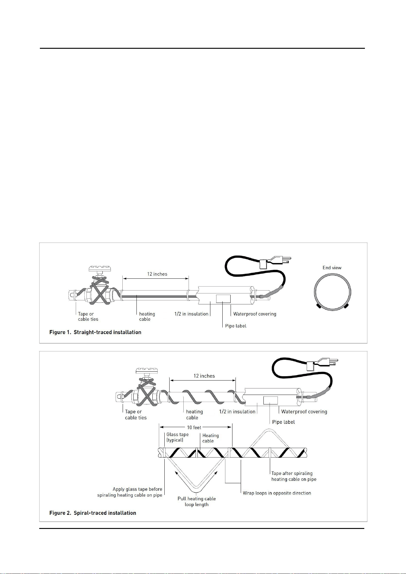
• Install heating cable, using straight tracing Figure 1, or spiraling Figure 2.
• For straight tracing, install the heating cable on a lower half of the pipe; for example, in the 4 o’clock or
8 o’clock position.
• Be sure to install the additional heating cable required for valves, flanges, etc. as shown in Figures 1
and 2.
• When the design calls for spiraling, begin by suspending a loop every 10 feet as shown in Figure 2. To
determine the loop length, divide the LTV length by your pipe length and multiply by 10. For example, if
you are using a 50 ft LTV on a 40 foot pipe, leave a 12-foot loop of heating cable at every 10-foot section
of pipe. Grasp the loop in its center and wrap it around the pipe. Even out the distance between spirals
by sliding the wraps along the pipe. Use glass tape to secure the center of the loop to the pipe.
• Fasten LTV heating cable to the pipe at 1-foot intervals using fiberglass application tape or nylon cable
ties. Do not use vinyl electrical tape, duct tape, metal bands, or wire.
• If excess cable remains at the end of the pipe, double it back along the pipe.
3. Check the installation.
• Prior to installing thermal insulation, make sure the heating cable is free of mechanical damage (from
cuts, clamps, etc.) and thermal damage (from solder, overheating, etc.).
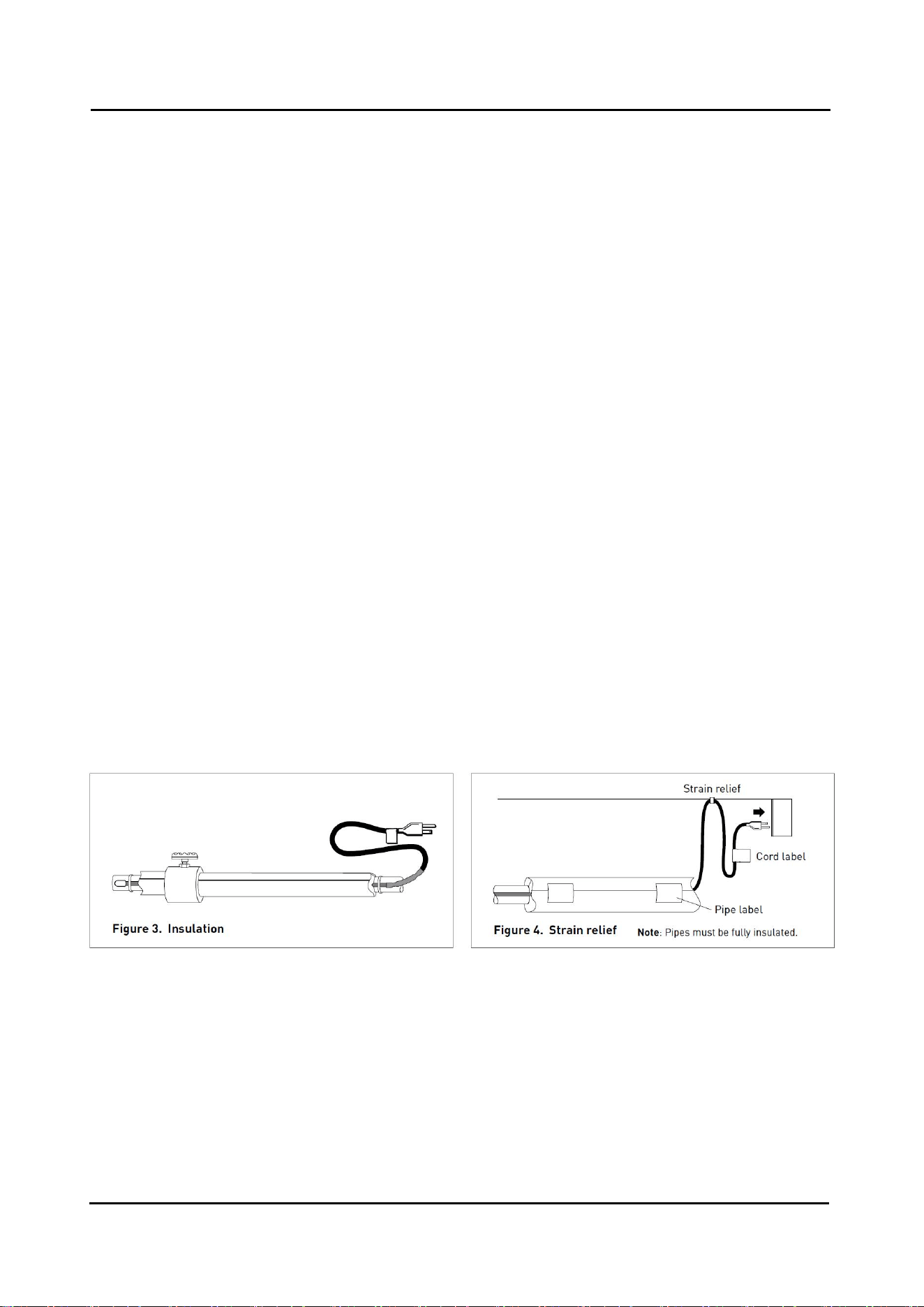
4. Install thermal insulation.
• A reliable LTV system depends on properly installed and dry, weatherproofed thermal insulation.
• Ensure that at least 1/2” of preformed foam or equivalent thermal insulation is used and that all piping,
including valves, joints, and wall penetrations, has been fully insulated as shown in Figure 3.
• For protection to -20°F (-29°C), use 1” thick insulation.
• Install the insulation on the piping as soon as possible to minimize the potential for mechanical damage
after installation.
• Be sure the LTV label is visible on the outside of the thermal insulation.
SFTRACE LTV SELF-REGULATING HEATING CABLES cCSAus
THERMAL MANAGEMENT SOLUTIONS | 6/11 | WUHU XUHUI ELECTRIC NEW MATERIAL CO., LTD
5. Finishing the installation.
• To prevent damage to the heating cable or cord, secure the power cord (cold lead) with a plastic cable
tie, glass cloth tape, or duct tape as shown in Figure 4.
• Two labels indicating the presence of electric pipe heating cable are included with the heating cable.
Attach the two “Electric Traced” labels on the outer surface of the pipe insulation at suitable intervals to
indicate the presence of LTV electric heating cable.
6. Starting the system.
• Xuhui recommends that the system be tested per the “Cable
testing and maintenance” section below.
• Plug the heating cable into a ground-fault protected outlet.
• Check the circuit breaker to verify power to the cable.
• Standing water in the pipe should feel warm within an hour.
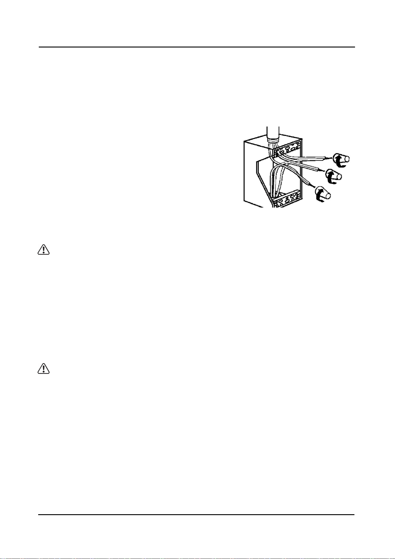
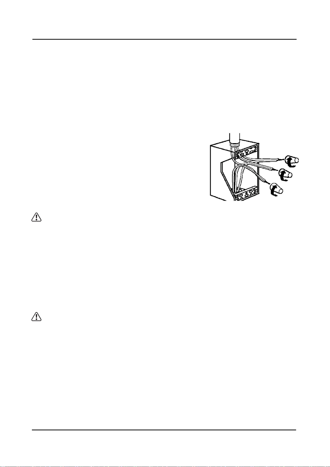
• For LTV with power cord but without plug, using CSA certified
or UL Listed Type 4X junction box and outlet bushing and wire
nuts (suitable for 12 to 18AWG wire size), connect the black
and white cold leads to both phase wires and the green cold
lead to ground.
• Check the circuit breaker to verify power to the cable.
Warning: De-energize circuit before servicing.
Cable testing and maintenance
Using a 500-Vdc megohmmeter, check the insulation resistance between both of the rectangular (power,
or black and white wire) prongs on the plug and the round (ground, or green wire) prong after installing
the heating cable. Minimum reading should be 50 megohms.
Record the original values for each circuit, and compare subsequent readings taken during regular
maintenance schedules to the original values.
If the readings fall below 50 megohms, replace the LTV cable with a new unit. Do not attempt to repair
the unit.
Warning: Fire and Shock Hazard.
Damaged heating cable can cause electrical shock, arcing, and fire. Do not attempt to repair or
energize damaged heating cable. Remove it at once and replace with a new length.
SFTRACE LTV SELF-REGULATING HEATING CABLES cCSAus
THERMAL MANAGEMENT SOLUTIONS | 7/11 | WUHU XUHUI ELECTRIC NEW MATERIAL CO., LTD
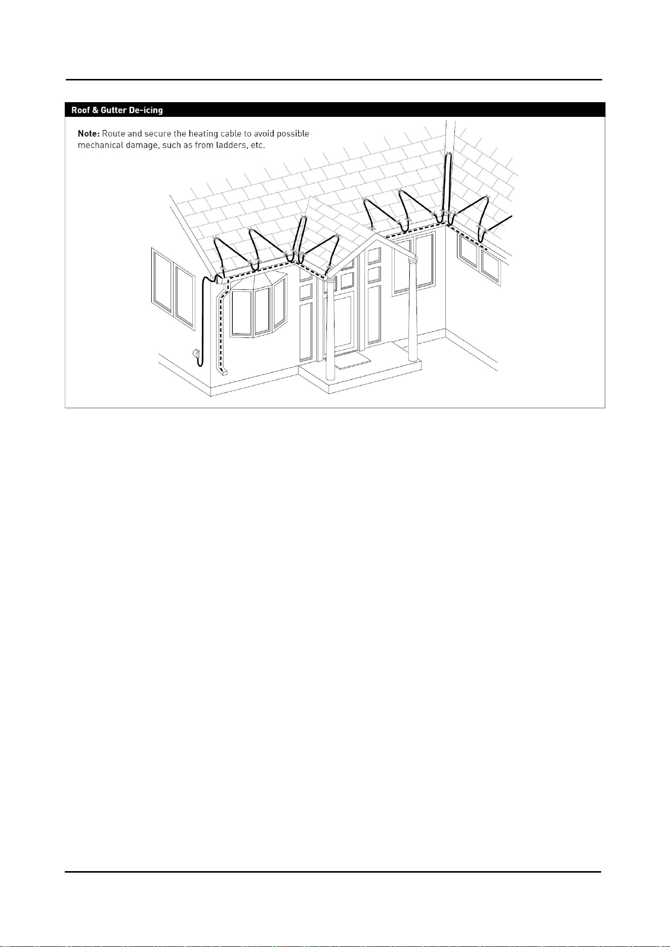
General requirements for roof & gutter de-icing:
• When used for roof and gutter de-icing, ensure that the roofing material is suitable for the heating
cable which has a maximum sheath temperature of 85C.
• LTV is designed to remove melt water, not accumulated snow.
• LTV heating cable will not keep snow or ice from falling off the roof. Snow fences or snow guards
should be used to eliminate snow movement. For the names of manufacturers of snow guards or snow
fences, contact Xuhui at 86-553-7477605.
• LTV heating cables may be used on:
- Roofs made from all types of standard roofing materials, including shake, shingle, rubber, tar, wood,
metal, and plastic.
- Gutters made from standard materials, including metal and plastic.
- Downspouts made from standard materials, including metal and plastic.
• Do not use an extension cord.
• Do not install the heating cable underneath any roof covering for roof and gutter de-icing.
• Install only in accessible locations; do not install behind walls or where the cable would be hidden.
• Do not run the heating cable through walls, ceilings, or floors.
• Connect only to ground-fault protected outlets that have been installed in accordance with all
prevailing national and local codes and standards and are protected from rain and other water.
Electrical codes
Article 426 of the National Electrical Code (NEC), and Part 1, Section 62 of the Canadian Electrical Code
(CEC), govern the installation of LTV heating cables for roof and gutter de-icing and must be followed.
Important: For the Xuhui warranty to be valid, you must comply with all the requirements outlined in
these guidelines.
All design information provided here is based on a “standard” shake or shingle roof application. For any
other application or method of installation, consult Xuhui at 86-553-7477605.

SFTRACE LTV SELF-REGULATING HEATING CABLES cCSAus
THERMAL MANAGEMENT SOLUTIONS | 8/11 | WUHU XUHUI ELECTRIC NEW MATERIAL CO., LTD
Heating cable selection for roof & gutter de-icing
Calculate the heating cable length.
Find the number of feet of heating cable needed per foot of roof edge in Table 3. Then, calculate the
amount of total heating cable length you need using the following formula:
Length = A + B + C + D
A Roof edge: Roof edge (ft) x Feet of heating cable per foot of roof edge
B Roof extension: Roof edge (ft) x 0.5*
C Roof gutter: Total gutter length (ft)
D Downspout: Total downspout length (ft) +1 (ft)
= Total heating cable length (ft)
* Roof extension: This length allows the heating cable to extend into the gutter to provide a continuous drain path, or
where no gutters are present, extends beyond the roof edge to form a drip loop.
Example: (shingle roof)
Eave overhang: 1 ft / 12 in
Roof edge: 15 ft
Roof gutter: 15 ft
Downspout: 15 ft
LTV heating cable required:
A Roof edge: 15 ft x 2.8 = 42.0 ft
B Roof extension: 15 ft x 0.5 = 7.5 ft
C Roof gutter: 15 ft = 15.0 ft
D Downspout: 15 ft + 1 ft = 16.0 ft
Total heating required: = 80.5 ft
Table 3. Typical spacing and layout measurements
Length of heating cable per foot of roof edge (feet) Standing seam metal roof:
Eave overhang (in)
Shingle roof
18 in seam
24 in seam
None
2
2.5
2
12
2.8
2.8
2.4
24
3.8
3.6
2.9
36
4.8
4.3
3.6
Note: Xuhui recommends the use of gutters and downspouts to provide a continuous path for melted
water.
• If downspout is in the middle of the run, loop the LTV down and back up. Double the length of the
downspout for determining the length of LTV to install.
• For valleys, run the heating cable two thirds of the way up and down the valley.
• For gutters 5-6 inches wide use 2 runs of heating cable.
• For gutters wider than 6 inches contact Xuhui, 86-553-7477605.
SFTRACE LTV SELF-REGULATING HEATING CABLES cCSAus
THERMAL MANAGEMENT SOLUTIONS | 9/11 | WUHU XUHUI ELECTRIC NEW MATERIAL CO., LTD
Heating cable installation
1. Prepare for installation.
• Store the heating cable in a clean, dry place.
• Use only the following Xuhui accessories to satisfy code and agency requirements:
- Hanger Bracket
- Roof Clips
• Make certain gutters and downspouts are free of leaves and other debris.
• Carefully plan the routing of the heating cable for roof and gutter de-icing.
2. Position and attach the heating cable on roofs.
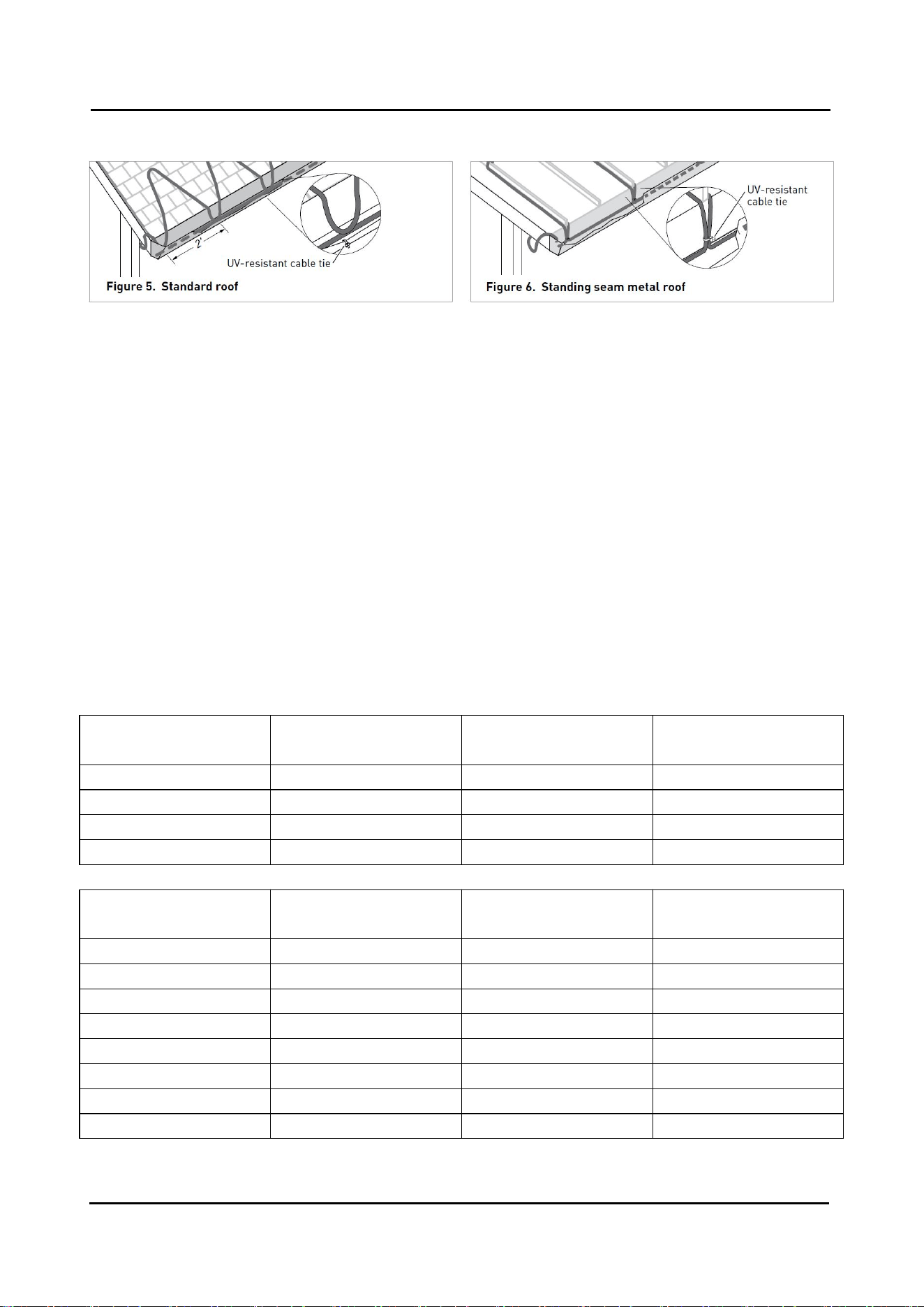
• Loop the heating cable on the overhang area of the roof. This is the part that extends past the building
wall. Extend the bottom of each heating cable loop over the roof edge and, using a UV-resistant cable tie,
connect the bottom of each loop to the cable running in the gutter to ensure a drainage channel off the
roof and into the gutter and downspout. The cable running in the gutter should remain against the bottom
of the gutter as shown in Figures 5 and 6.
Table 4. Tracing heights for different roof styles
Shake and Shingle Roof
Roof of overhang (in)
Tracing width (in)
Tracing heights (in)
Feet of LTV per
foot of roof edge
None*
2
18
2
12
2
18
2.8
24
2
30
3.8
36
2
42
4.8
Standing Seam Metal Roof**
Eave overhang (in)
Standing Seam
Spacing (in)
Tracing heights (in)
Feet of LTV per
foot of roof edge
None*
18
18
2.5
12
18
24
2.8
24
18
36
3.6
36
18
48
4.3
None*
24
18
2.0
12
24
24
2.4
24
24
36
2.9
36
24
48
3.6
* Gutter required
** No additional heating cable is required for gutters when tracing standing seam metal roofs
SFTRACE LTV SELF-REGULATING HEATING CABLES cCSAus
THERMAL MANAGEMENT SOLUTIONS | 10/11 | WUHU XUHUI ELECTRIC NEW MATERIAL CO., LTD
• Extend the top of each heating cable loop
beyond where the wall joins the roof.
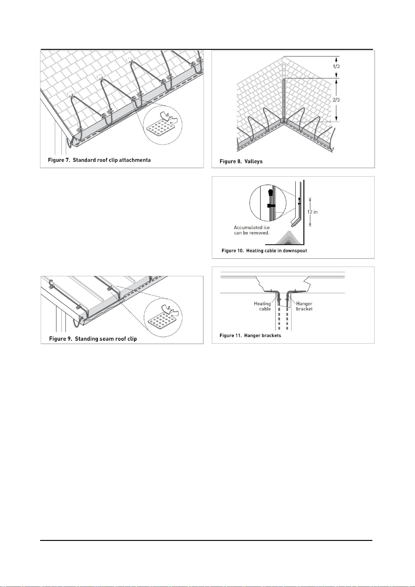
• Trace two-thirds of the way up each valley with a
double run of heating cable as shown in Figure 8.
• Use roof clips to route heating cable into and out
of the gutter in such a way as to prevent abrasion to
the cable. Protect all cable that protrudes past the
lower opening of the downspout.
• Ten roof clips for approximately 7 linear feet of roof edge. 50 roof clips for approximately 35 linear feet
of roof edge.
• Roof clips may be attached to a shake or shingle roof with nails or screws as shown in Figure 7. Roof
clips may be attached to a metal roof using screw, nail or adhesive as shown in Figure 9. Reseal the nail
or screw holes if necessary before installing heating cable in the clips.
• A barrier (snow fence) can be placed on the roof above the heating cable. This prevents damage to
the cable and keeps the installation from coming loose due to ice slides. The heating cable can be
attached to the barrier with UV-resistant cable ties, instead of using roof clips, if desired. Do not use wire
or other materials because they may damage the heating cable.
In gutters and downspouts
• Run heating cable along gutters and into downspouts, ending below the freezing level. Permanent
attachment of the cable to the gutter bottom is not necessary. Loop the heating cable in downspouts. Do
not leave the end of the LTV in air at the end of the downspout as shown in Figure 10.
• Use Hanger Brackets at the gutter/downspout transition to protect the heating cable from fraying and
from damage from sharp edges and to provide strain relief as shown in Figure 11.
• Route and secure cable to avoid possible mechanical damage, such as from ladders, etc.
SFTRACE LTV SELF-REGULATING HEATING CABLES cCSAus
THERMAL MANAGEMENT SOLUTIONS | 11/11 | WUHU XUHUI ELECTRIC NEW MATERIAL CO., LTD
3. Mark the installation.
Two labels indicating the presence of electric de-icing and snow-melting equipment on the premises are
included with the heating cable. One label must be posted at the electrical outlet cover. The other label
must be posted at the fuse or circuit breaker panel. The labels must be clearly visible.
4. Check the installation.
• Prior to plugging in, check to be sure the heating cable is free of mechanical damage (cuts, clamps,
etc.).
• Using a megohmmeter, test each circuit according to the instructions in the “Heating cable testing and
maintenance” section on next page.
5. Starting the system.
• Xuhui recommends that the system be tested per the “Cable
testing and maintenance” section below.
• Plug the heating cable into a ground-fault protected outlet.
• For LTV with power cord but without plug, using CSA certified or
UL Listed Type 4X junction box and outlet bushing and wire nuts
(suitable for 12 to 18AWG wire size), connect the black and white
cold leads to both phase wires and the green cold lead to ground.
• Check the circuit breaker to verify power to the cable.
Warning: De-energize circuit before servicing.
Heating cable testing and maintenance
Make sure that gutter and downspouts are free of leaves and other debris prior to the winter season.
Using a 500-Vdc megohmmeter, check the insulation resistance between both of the rectangular (power,
or black and white wire) prongs on the plug and the round (ground, or green wire) prong after installing
the heating cable. Minimum reading should be 50 megohms.
Record the original values for each circuit. Take additional readings during regularly scheduled
maintenance and compare to the original value. If the readings fall below 50 megohms, inspect heating
cables and insulation for signs of damage.
Warning: Fire and Shock Hazard.
Damaged heating cable can cause electrical shock, arcing, and fire. Do not attempt to repair or
energize damaged heating cable. Remove it at once and replace with a new length.