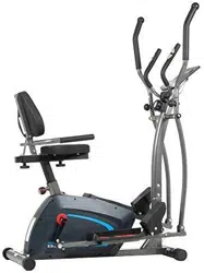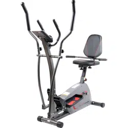
BRT7989/BRT7200
OWNER’S MANUAL
This product is intended for indoor, home use only and is not to be used in a commercial setting.
U.S. Patent number US9474925B1
BRT7989/7200 Page 1
PLEASE KEEP THESE INSTRUCTIONS FOR FUTURE USE & REFERENCE.
DO NOT DISCARD.
WARNING: SERIOUS INJURIES AND EVEN DEATH CAN OCCUR IF THE PROPER SAFETY PRECAUTIONS
ARE NOT FOLLOWED.
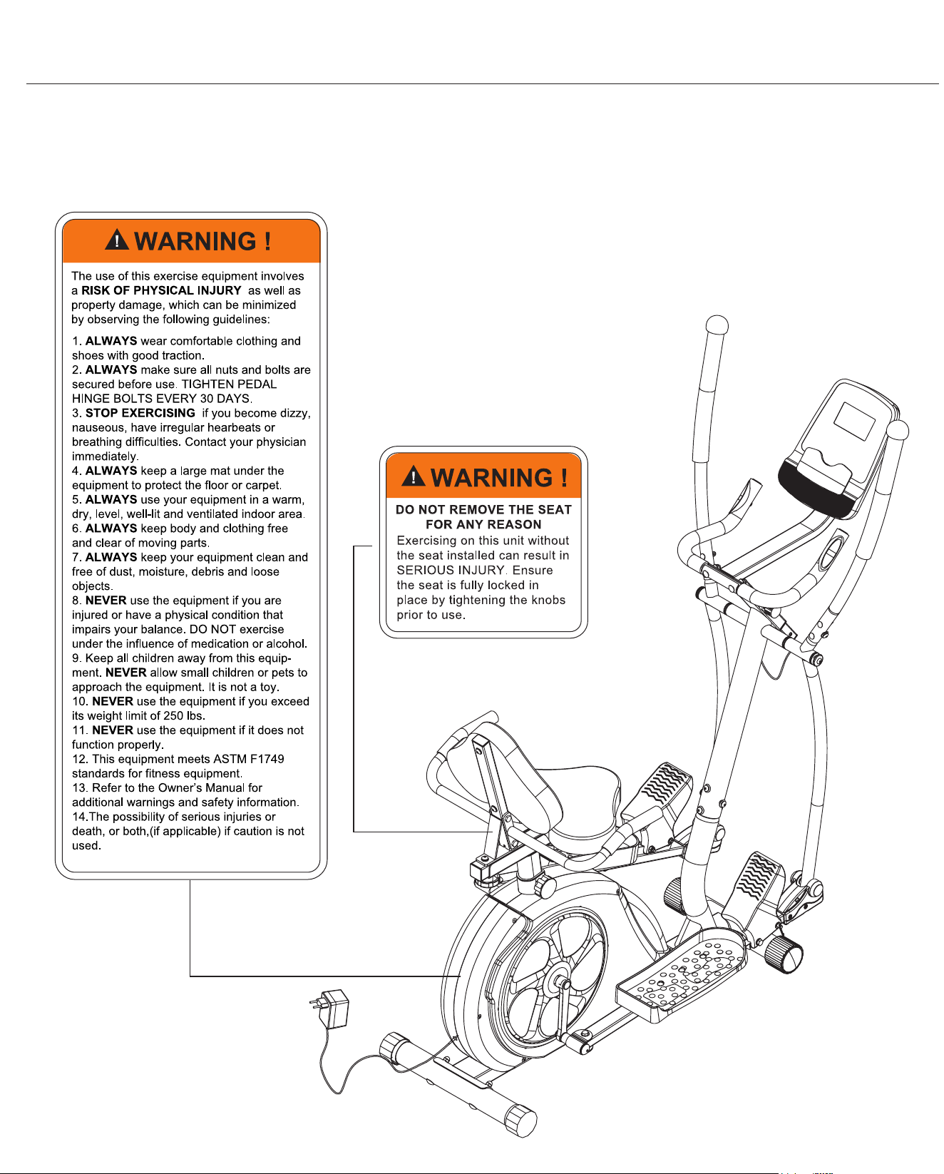
The diagram below highlights and reviews many of the important Safety and Warning labels also found on the unit.
Please ensure any user of the unit familiarizes themselves with this Safety and Warning guidelines before use.

BRT7989/7200 Page 2
Before you undertake any exercise program, please be sure to
consult with your doctor.
Frequent strenuous exercise should be approved by your
doctor and proper use of your product is essential.
Excessive or incorrect training may result in health injuries.
Please read this manual carefully before commencing the
assembly of your product or starting to exercise.
• Please keep all children away from this item when in use.
Do not allow children to climb or play on this item when it
is not in use.
• Supervise teenagers while they use this unit.
• For your own safety, always ensure that there are at least
3 feet of free space in all directions around your product
while you are exercising.
• Regularly check to see that all nuts, bolts and ttings are
securely tightened. Periodically check all moving parts for
obvious signs of wear or damage.
• Any adjustment devices that could interfere with the user’s
movement of this unit should not be left projecting.
• Clean only with a damp cloth, do not use solvent
cleaners. Lubricate the moving parts of your unit every 30
days with a silicone-based grease or product.
If you are in any doubt, do not use your product; contact
CUSTOMER SUPPORT.
• Before use, always ensure that your product is positioned
on a solid, hard-at surface.
• Do not place on carpet. If necessary, use a rubber mat
underneath to reduce the possibility of slipping.
• Always wear appropriate clothing and footwear such as
training shoes when exercising. Do not wear loose clothing
that could become caught in moving parts during exercise.
• Do not use this unit if it is not functioning properly or if it is
not fully assembled.
• Do not use this unit for commercial purposes. This unit is
for home use only.
• Before use, you must read and understand all instructions
& warnings stated in this Owner’s Manual as well as
posted on the equipment.
• It is the facility owner’s responsibility to properly instruct
users on the proper operation of the equipment and to
warn them of the potential hazards.
• If at any time during exercise you feel faint, dizzy or
experience pain, stop and consult your physician.
Your product is intended for use in clean dry conditions. You
should avoid storage in excessively cold or damp places as
this may lead to corrosion and other related problems.
If you have any questions concerning the assembly of your
item or if any parts are missing, please DO NOT RETURN
THE ITEM TO THE STORE OR CONTACT THE
RETAILER.
Our dedicated customer service sta can help you with
any questions you may have regarding the assembly of this
unit and can also mail you replacement parts.
Customer Support is open 9:00 a.m. to 5:00 p.m. (Pacic
Time) Monday through Friday.
Please contact us by any of the following means :
Body Flex Sports, Inc.
21717 Ferrero Parkway, Walnut, CA 91789
Telephone: 1 (888) 266 - 6789
Fax: 1 (909) 598 - 6707
Email: info@bodyexsports.com
Body Flex Sport warrants your product is free of any defects in
workmanship and materials for a period of 1 year for the frame
and 90 days on all parts if the item is used for the
intended purpose, properly maintained and not used
commercially.
Any alterations or incorrect assembly of the product will void
this warranty.
Proof of purchase must be presented for any warranty
validation (no exceptions). This warranty applies to the original
purchaser only and is not transferable.
This warranty covers parts damaged due to defect in work-
manship and materials; it does not cover abuse or damages
caused during use, storage or assembly. During the warranty
period, Body Flex Sport reserves the right to:
1. provide replacement parts to the purchaser in an eort to
repair the item.
2. repair the product returned to our warehouse
(at purchaser’s cost).
3. replace the product if neither of the two previously
- Ruler with both Metric and English measurements
- 2 x Adjustable Wrenches
- 1 x Philips (”Crosshead”) Screw Driver
Your product is suitable for users weighing:
250 pounds or less
General Information
Safety Storage and Use
Questions
Customer Support
Warranty
Assembling Tools
Weight Limit
BRT7989/7200 Page 3
Before Assembly
1. Take a few minutes to familiarize yourself with the parts and hardware included with your product.
2. The assembly may require two people.
3. Check the frame for any damage and check any wiring (if present) for rips or tears. If you detect damage, rips, or
tears, please contact our Customer Support Team before beginning any assembly.
4. Make sure all the hardware needed is included.
5. It is very important to follow the assembly instructions correctly and to make sure all parts are attached correctly and
rmly tightened when the assembly process is complete.
6. Parts that are not tightened correctly will seem loose and can cause irritating noises and will cause damage to the
equipment.
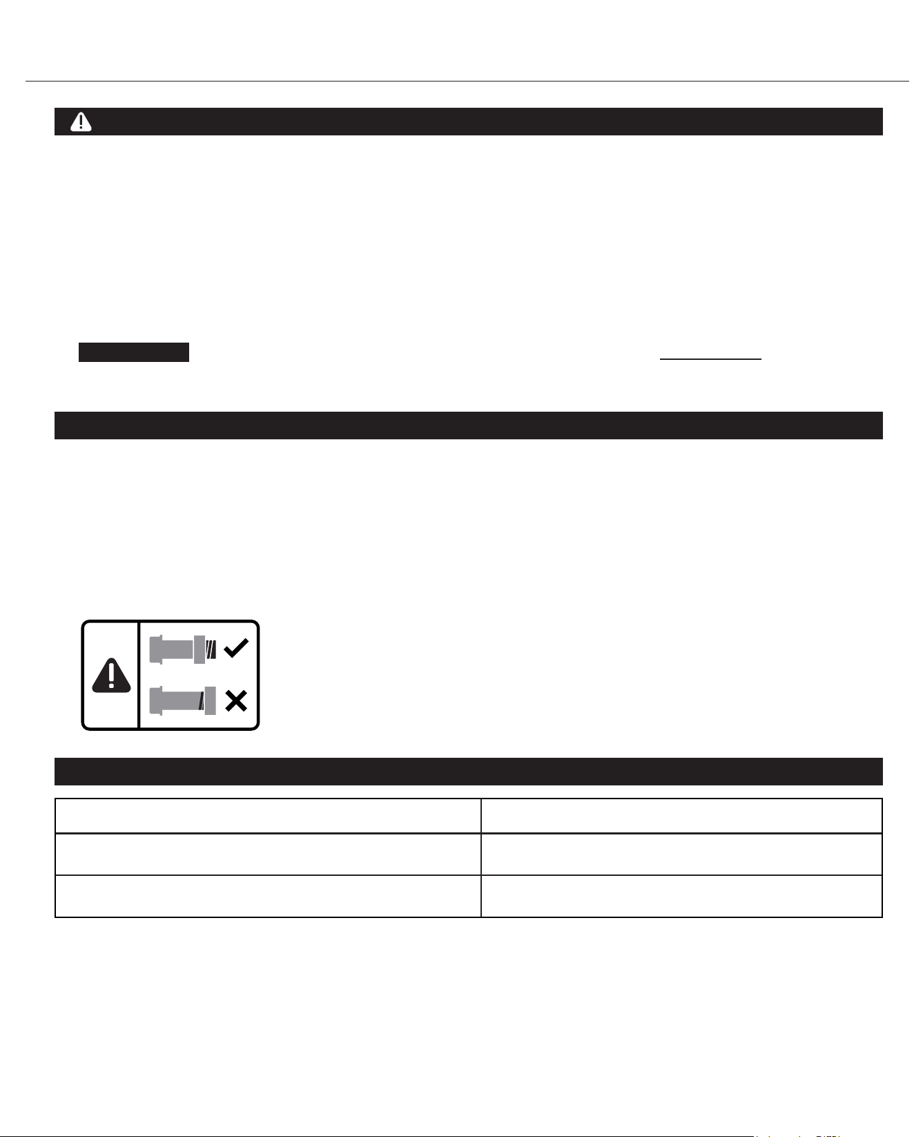
1. It is only necessary to tighten the bolts and nuts to “nger tight” during the assembly process. This will make it
easier to complete certain steps by allowing more tolerance for all the parts to t properly.
2. Do not tighten all the nuts onto the bolts securely until after you have completed assembly of your product.
3. Use wrenches, pliers, or ratchet and sockets to tighten the bolts and nuts.
4. The Nylon Nut should thread onto the Hex Bolt until the end of the Hex Bolt has passed through the Nylon insert
inside the Nut. Please follow this guideline every time you see this Nylon Nut icon throughout the assembly steps.
Nylon Lock Safety Nuts
Tools Required For Assembly
WARNING
PLEASE NOTE : Many of the parts and hardwares listed on the parts list are already pre-assembled or
installed on the unit.
Tool Description/Purpose
Ruler (with both Metric and English measurements)
QTY: 1
Use to measure the length or size of hardware including
bolts to ensure you are using the correct part.
Adjustable or at wrenches
QTY: 2
Use to securely install parts including nuts and bolts.

BRT7989/7200 Page 4
Part Listing
The following parts list describes all of the parts illustrated in the exploded diagram on the following page.
PLEASE NOTE: most of these parts are already pre-assembled on your unit.
# Description
01 Main Frame
02 Center Post
03 Left Pedal Tube
04 Right Pedal Tube
05 Left Couple Bar
06 Right Couple Bar
07 Seat Post
08 Seat Cushion Frame
09 Backrest Cushion Frame
10 Left Rear Handle Bar
11 Right Rear Handle Bar
12 Monitor Frame
13 Pulse Handle Bar
14 Left Handle Bar
15 Right Handle Bar
16 Front Stabilizer
17 Rear Stabilizer
18 Pedal Connection Joint
19 Axle
20 U Bracket
21 Crank
22 Spring Loaded Knob (M16)
23 Spring Loaded Knob (M16)
24 Knob Bolt (M10)
25 Carriage Bolt (M8x70 mm)
26 Carriage Bolt (M8x45 mm)
27 Carriage Bolt (M6x38 mm)
28 Pedal Hinge Bolt (1/2"x97 mm)
29 Bolt (M10x58 mm)
30 Bolt (M8x45 mm)
31 Bolt (M8x20 mm)
32 Bolt (M8x15 mm)
33 Hex Bolt (M8x105 mm)
34 Hex Bolt (M8x60 mm)
35 Hex Bolt (M8x45 mm)
36 Hex Bolt (M8x40 mm)
37 Hex Bolt (M8x20 mm)
38 Screw (M5x10 mm)
39 Screw (M4x12 mm)
40 Screw (M4x25 mm)
41 Washer (M4)
42 Cap Nut (M8)
43 Cap Nut (M6)
44 Nylon Nut (1/2")
45 Nylon Nut (M10)
46 Nylon Nut (M8)
# Description
47 Spring Washer (M8)
48 Spring Washer (M6)
49 Arc Washer (M8)
50 Arc Washer (M6)
51 Washer (M10)
52 Washer (M8)
53 D Shape Washer
54 Wavy Washer (19 mm)
55 Wavy Washer (16 mm)
56 Bushing
57 Left Pedal
58 Right Pedal
59 Left Foot Pedal
60 Right Foot Pedal
61
62 Pedal
Tube Front Cover (Left)
63 Pedal Tube Front Cover (Right)
64 Main Frame Sleeve
65
Mat
Rectangular Sleeve
66 Rectangular End Cap (25x50 mm)
67 Rectangular End Cap (23x53 mm)
68 Rectangular End Cap (25x40 mm)
69 Square End Cap (38 mm)
70 End Cap for Rear Stabilizer
71 End Cap for Front Stabilizer
72 Round End Cap (30 mm)
73 Round End Cap (25 mm)
74 Plastic Bushing (25 mm)
75 Plastic Bushing (32 mm)
76 Round End Cap (32 mm)
77 Handle Bar Foam Grip
78 Pulse Handle Bar Foam Grip
79 Rear Handle Bar Foam Grip
80 Seat Cushion
81 Backrest Cushion
82 Monitor
83 Adapter
84 Pulse Sensor
85 Pulse Sensor Wire
86 Main Sensor Wire (Upper)
87 Main Sensor Wire (Middle)
88 Main Sensor Wire (Lower)
89
Pop-pin
90 Tool 1
91 Tool 2
92 Wire Cap
93 Screw (M4x15 mm)
94 Screw (M5x10 mm)
BRT7989/7200 Page 5
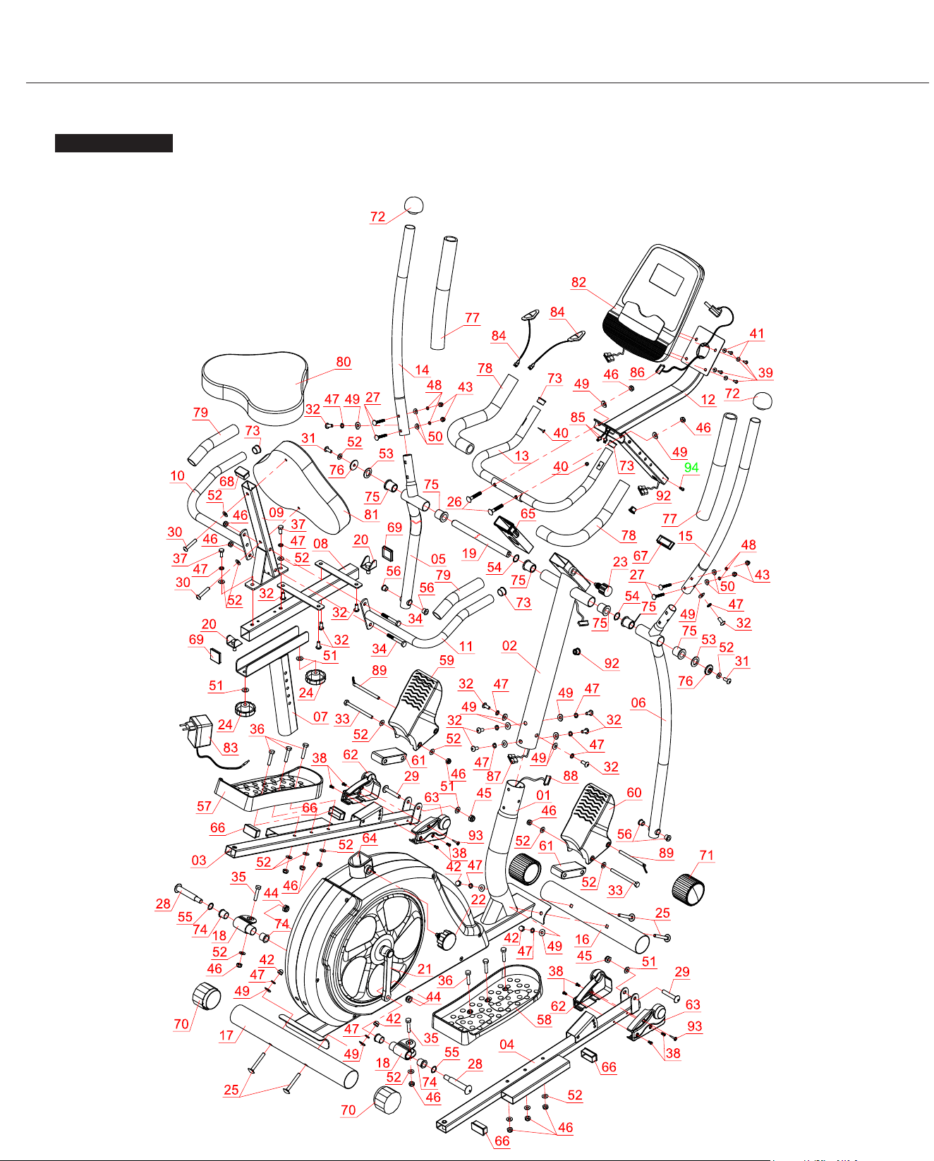
Exploded View
The following diagram is provided to help you familiarize yourself with the parts and hardware that will be used during the
assembly process.
: : Not all of the parts and hardware you see here will be used while you are assembling the machine
because some of these items are already pre-installed. Please use this page only as a reference guide for parts and
hardware.
PLEASE NOTE
BRT7989/7200 Page 6
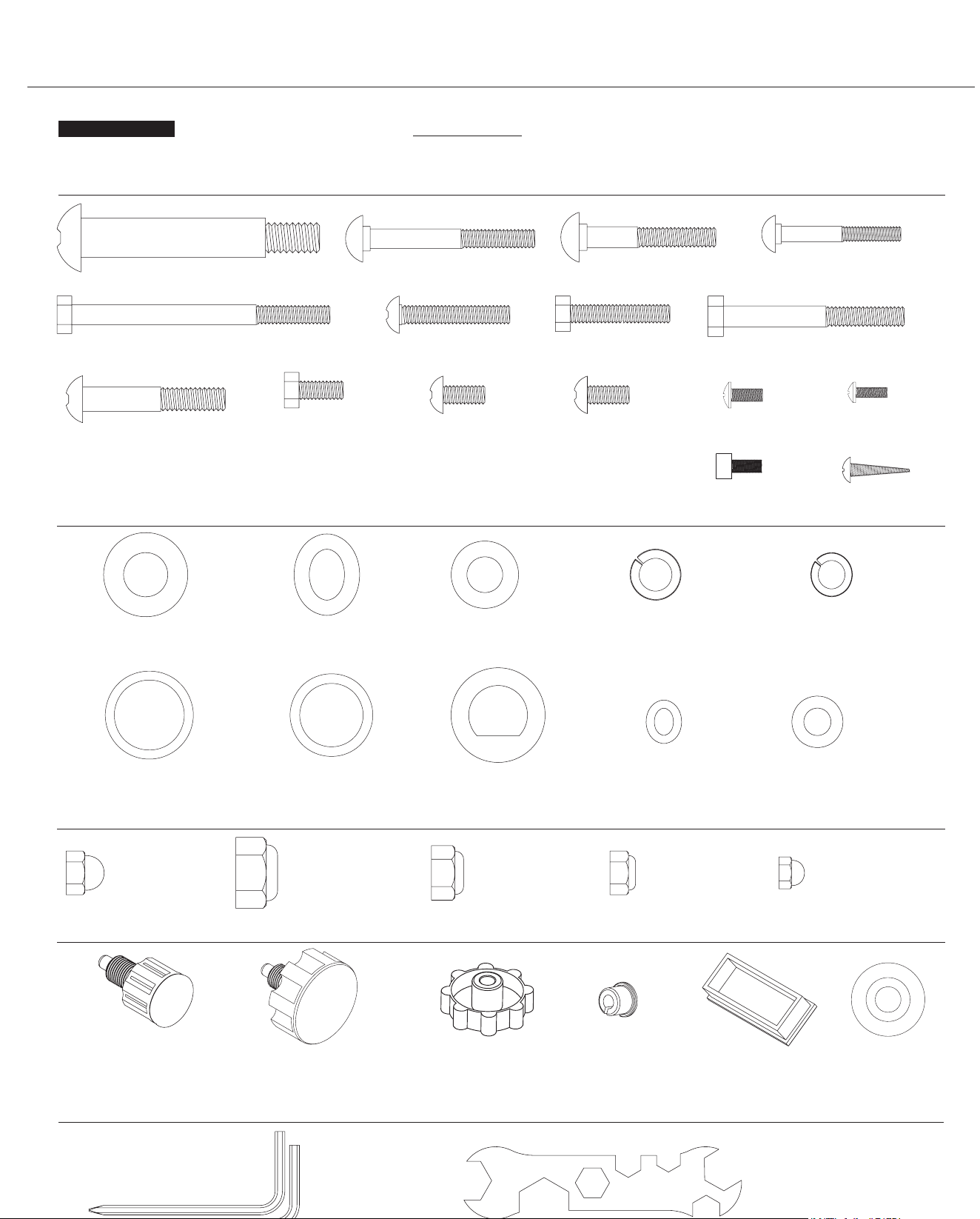
Hardware and Tool List
Bolts
Washers
Nuts
Others
Tools (Included)
The following hardware is used to assemble your unit. Please take a moment to familiarize yourself with these items.
PLEASE NOTE: Most of these parts are already pre-assembled on your unit. Do not be alarmed if you see parts on this
page that are not included in your hardware packet.
#47 Spring Washer (M8)
[14 pieces]
[6 pieces pre-assembled]
#41 Washer (M6)
[4 pieces pre-assembled]
#48 Spring
Washer (M6)
[4 pieces]
#54 Wavy Washer (Ø19mm)
[2 pieces]
#28 Pedal Hinge Bolt (1/2" x 97mm)
[2 pieces]
#33 Hex Bolt (M8 x 105mm)
[2 pieces]
#37 Hex Bolt (M8 x 20mm)
[2 pieces]
#32 Bolt (M8 x 15mm)
[12 pieces]
[6 pieces pre-assembl
ed]
#31 Bolt (M8 x 20mm)
[2 pieces]
#38 Screw (M5 x 10mm)
[8 pieces]
#39 Screw (M4 x 12mm)
[4 pieces pre-assembled]
#30 Bolt (M8 x 45mm)
[2 pieces]
#36 Hex Bolt (M8 x 40mm)
[6 pieces]
#34 Hex Bol
t (M8 x 60mm)
[2 pieces]
#25 Carriage Bolt (M8 x 70mm)
[4 pieces]
#26 Carriage Bolt (M8 x 45mm)
[2 pieces]
#27 Carriage Bolt (M6 x 38mm)
[4 pieces]
#29 Bolt (M10 x 58mm)
[2 pieces]
#93 Screw (M4 x 15 mm)
[2 pieces]
#55 Wavy Washer (Ø16mm)
[2 pieces]
#53 D Shape
Washer (19mm)
[2 pieces]
#51 Washer (M10)
[4 pieces]
[2 pieces pre-assembled]
#52 Washer (M8)
[16 pieces]
#90 Tool 1 (5mm)
[2 pieces]
#91 Tool 2
[2 pieces]
#23 Spring Loaded Knob (M16)
[1 piece pre-assembled]
#22 Spring Loaded Knob (M16
)
[1 piece]
#92 Wire Cap
[2 pieces]
#67 Rectangular End Cap
[1 piece]
#76 Round Cap
[2 pieces]
#49 Arc Washer (M8)
[14 pieces]
[6 pieces pre-assembled]
#50 Arc Washer (M6)
[4 pieces]
#94 Screw (M5 x 10mm)
[1 piece]
#42 Cap Nut (M8)
[4 pieces]
#43 Cap Nut (M6)
[4 pieces]
#44 Nylon Nut (1/2")
[2 pieces]
#45 Nylon Nut (M10)
[2 pieces]
#46 Nylon Nut (M8)
[12 pieces]
#24 Knob Bolt
[2 piece pre-assembled]
BRT7989/7200 Page 7
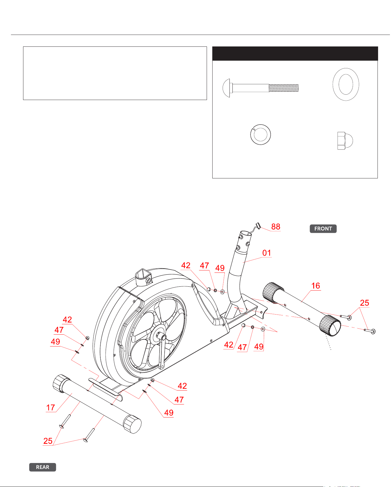
Assembly STEP 1
FRONT STABILIZER ASSEMBLY
Using the drawing below for reference, secure the Front Stabilizer
(#16) to the Main Frame (#01) using a total of two Carriage Bolts
(#25), two Arc Washers (#49), two Spring Washers (#47) and two
Cap Nuts (#42).
REAR STABILIZER ASSEMBLY
Secure the Rear Stabilizer (#17) to the Main Frame (#01) using
a total of two Carriage Bolts (#25), two Arc Washers (#49), two
Spring Washers (#47) and two Cap Nuts (#42).
Please Note that the Front Stabilizer (#16) has end caps that spin
for ease of relocating the unit and the Rear Stabilizer (#17) has
height adjustable end caps for leveling of the unit.
Hardware Required
Front Roller
NOTE BEFORE STARTING THE ASSEMBLY PROCESS :
To avoid misalignment due to over-tightening, please do not use a
wrench and use only hand-tightening for now to ensure
easy assembly.
Wrench-tightening should be performed after all parts are assembled
to ensure all nuts, bolts, and parts are tightly secured before use.
#47 Spring Washer (M8)
[4 pieces]
#25 Carriage Bolt (M8 x 70mm)
[4 pieces]
#42 Cap Nut (M8)
[4 pieces]
#49 Arc Washer (M8)
[4 pieces]
BRT7989/7200 Page 8
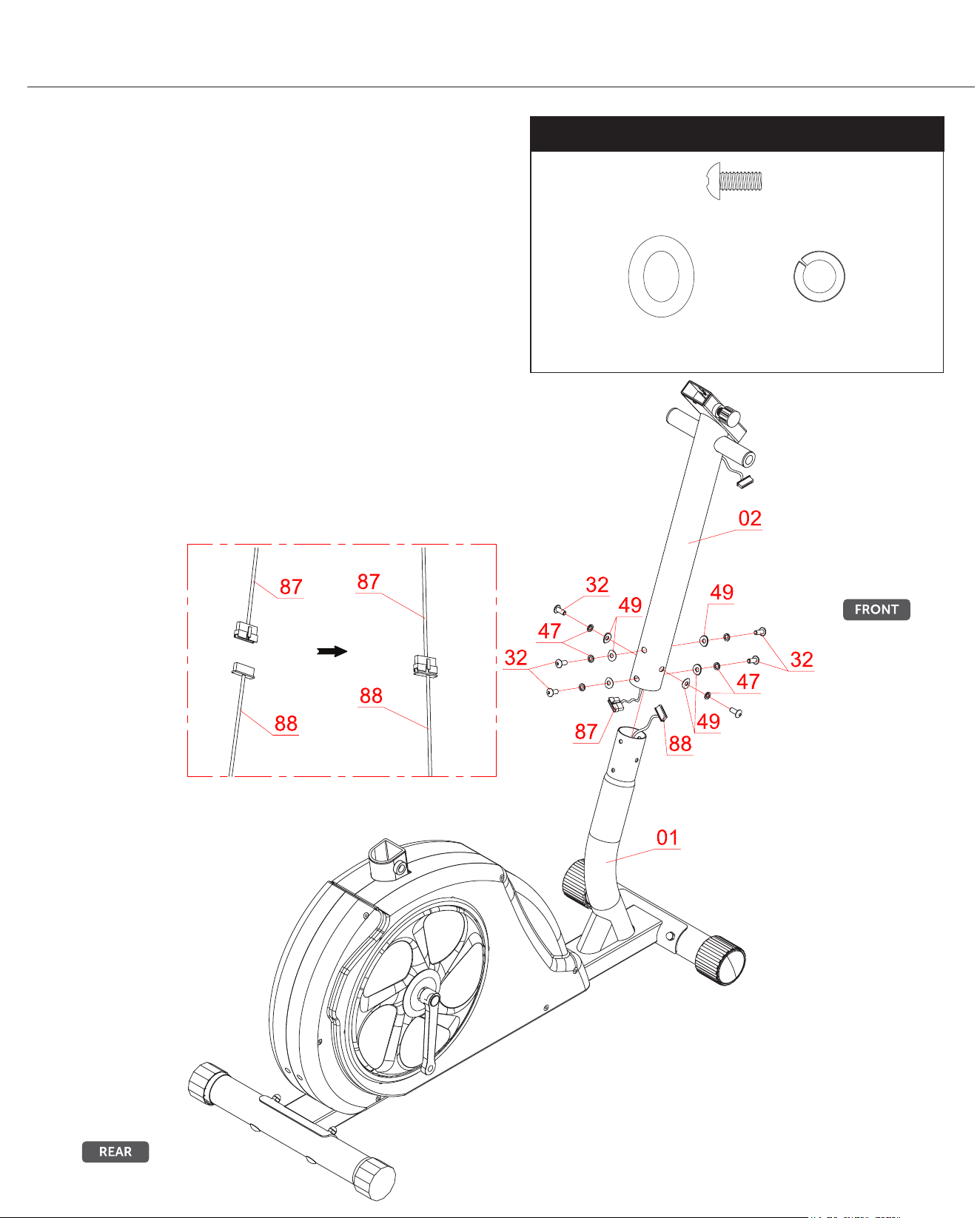
Assembly STEP 2
WIRE CONNECTIONS
Connect the Main Sensor Wire (Lower)(#88) to the Main
Sensor Wire (Middle)(#87).
CENTER POST ASSEMBLY
Remove the Bolts (32), Spring Washers (#47) and Arc
Washers (#49) that are pre-assembled on the Center Post
(#02) and set them aside as they will be used in a later
process.
Slide the Center Post (#02) onto the Main Frame (#01) and
secure it using a total of six Bolts (#32), six Spring Washers
(#47) and six Arc Washers (#49) as shown in drawing below.
Hardware Required
#47 Spring Washer (M8)
[6 pieces]
#32 Bolt (M8 x 15mm)
[6 pieces]
#49 Arc Washer (M8)
[6 pieces]
BRT7989/7200 Page 9
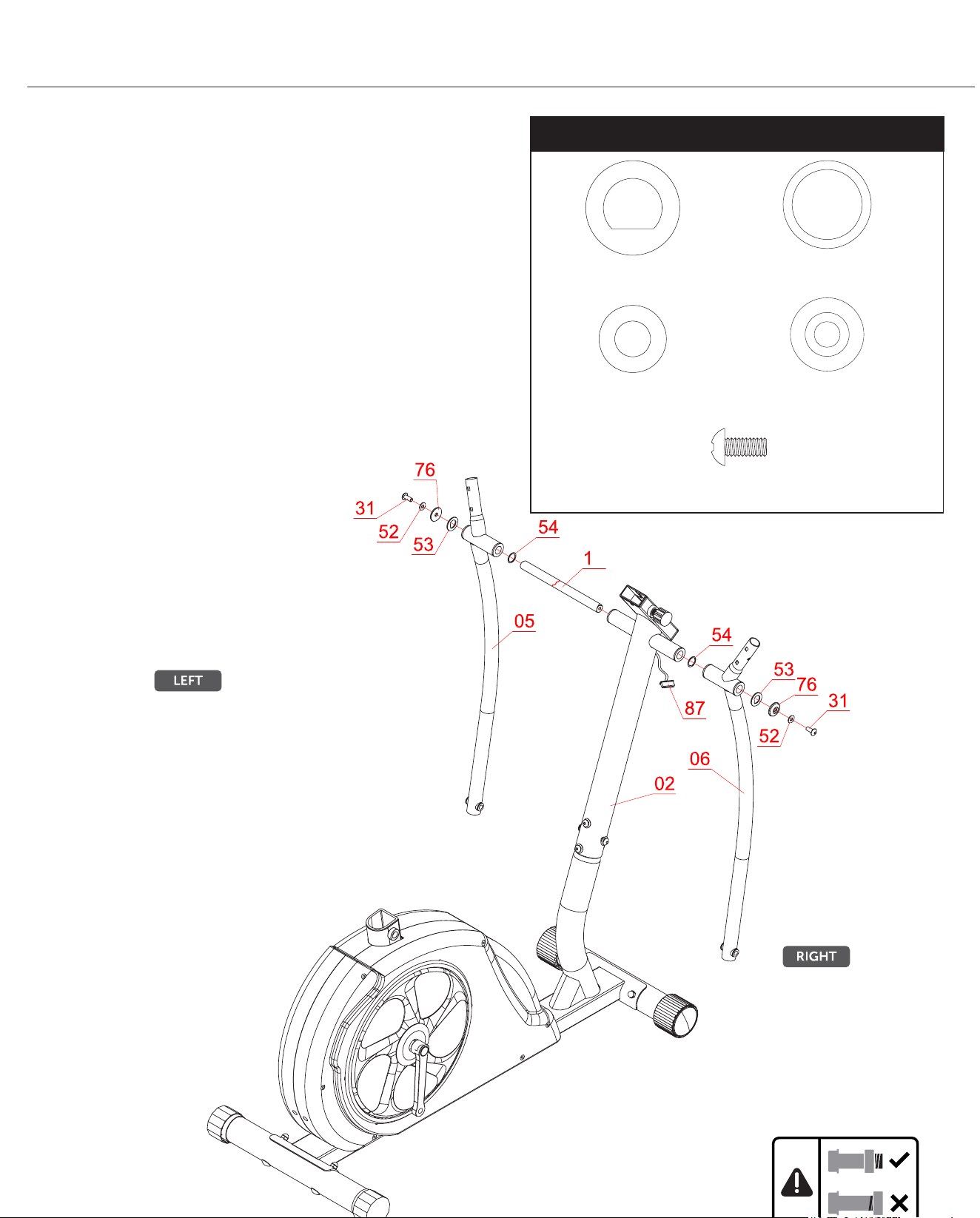
Assembly STEP 3
Hardware Required
COUPLER BAR ASSEMBLY (Part I)
Referring to the drawing below, insert the Axle (#19) through the
horizontal stems on the Center Post (#02). Then, on the left side of
the Axle (#19) -- in the following order, slide one Wavy Washer
(#54) followed by the Left Coupler Bar (#05), one D Shape Washer
(#53), one Round Cap (#76), one Washer (#52), and secure using
one Bolt (#31).
On the opposite side of the Axle (#19), assemble -- in the following
order: one Wavy Washer (#54) followed by the Right Coupler Bar
(#06), one D Shape Washer (#53), one Round Cap (#76), one
Washer (#52), and secure using one Bolt (#31).
9
#54 Wavy Washer (Ø19mm)
[2 pieces]
#31 Bolt (M8 x 20mm)
[2 pieces]
#53 D Shape Washer (19mm)
[2 pieces]
#52 Washer (M8)
[2 pieces]
#76 Round Cap
[2 pieces]
BRT7989/7200 Page 10
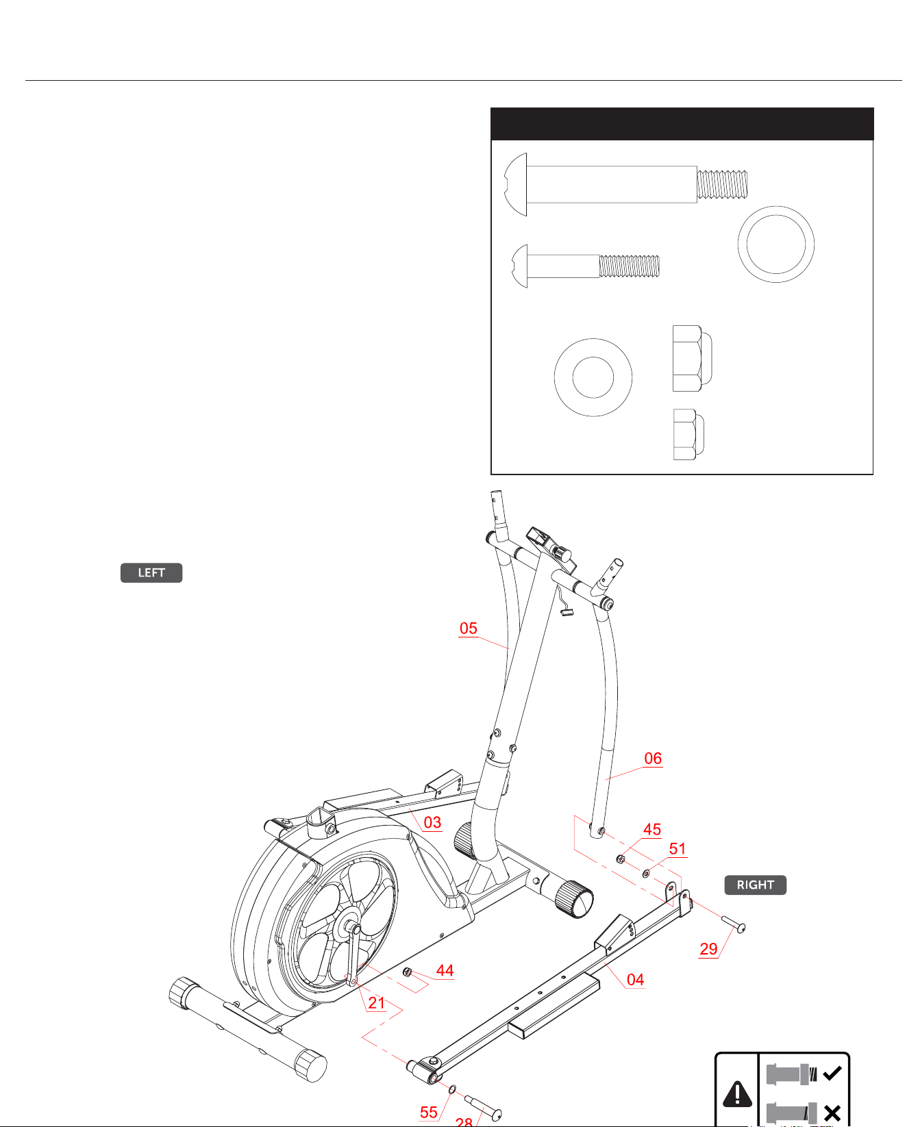
Assembly STEP 4
Hardware Required
COUPLER BAR ASSEMBLY (PART II)
Attach the Right Pedal Tube (#04) onto the Crank (#21) as
illustrated and secure by inserting from the outer edge of the Right
Pedal Tube (#04), one Pedal Hinge Bolt (#28) and one Wavy
Washer (#55). Secure from the inner edge (behind the Crank(#21))
with one Nylon Nut (#44).
*** PLEASE DO NOT tighten the hardware until steps below have
been completed. This will allow you to align the holes for proper
and smooth assembly.***
Repeat this process on the other side using the Left Pedal Tube
(#03).
Using the drawings as a reference, attach the free end of the bottom
of the Right Coupler Bar (#06) to the front of the Right Pedal Tube
(#04) by aligning the holes. After the holes are aligned, insert one Bolt
(#29) through the Right Pedal Tube (#04), the Right Coupler Bar
(#06) and secure using one Washer (#51) followed by one
Nylon Nut (#45).
Repeat this process on the other side using Left Coupler Bar (#05)
and Left Pedal Tube (#03).
***NOW, you may tighten the hardware on both sides.***
#28 Pedal Hinge Bolt (1/2" x 97mm)
[2 pieces]
#29 Bolt (M10 x 58mm)
[2 pieces]
#55 Wavy Washer (Ø16mm)
[2 pieces]
#51 Washer (M10)
[2 pieces]
#44 Nylon Nut (1/2")
[2 pieces]
#45 Nylon Nut (M10)
[2 pieces]
BRT7989/7200 Page 11
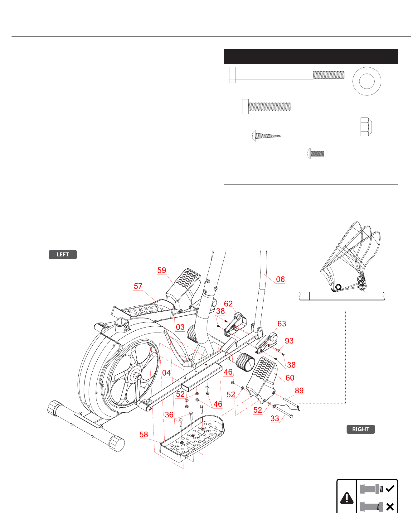
Assembly STEP 5
Hardware Required
PEDAL ASSEMBLY
Attach the Left/Right Pedals (#57/#58) onto the Left/Right Pedal
Tubes (#03/#04) as shown in the drawing below using a total of six
Hex Bolts (#36), six Washers (#52), and six Nylon Nuts (#46).
FOOT PEDAL ASSEMBLY
On the right side, attach the Right Foot Pedal (#60) to the front of
Right Pedal Tube (#04) using one Hex Bolt (#33) through Pop-pin
(#89) safety ring and one Washer (#52), secure with one Washers
(#52) and one Nylon Nut (#46). Then insert a Pop-pin (#89) into the
front hole of the Right Foot Pedal (#60).
Repeat this process on the other side.
PEDAL TUBE FRONT COVER ASSEMBLY
Attach the Pedal Tube Front Cover (Left)(#62) to the Pedal Tube
Front Cover (Right)(#63) to the bottom corner (which connects the
Right Coupler Bar (#06) and Right Pedal Tube (#04)) and secure
using four Screws (#38) and one Screw (#93).
Repeat the covers assembly on the opposite side.
Front Foot Pedal with 3 settings
#33 Hex Bolt (M8 x 105mm)
[2 pieces]
#38 Screw (M5 x 10mm)
[8 pieces]
#36 Hex Bolt (M8 x 40mm)
[6 pieces]
#93 Screw (M4 x 15mm)
[2 pieces]
#52 Washer (M8)
[10 pieces]
#46 Nylon Nut (M8)
[8 pieces]
BRT7989/7200 Page 12
Assembly STEP 6
#46 Nylon Nut (M8)
[2 pieces]
#23 Spring Loaded Knob (M16)
[1 piece]
#92 Wire Cap
[2 pieces]
#67 Rectangular End Cap
[1 piece]
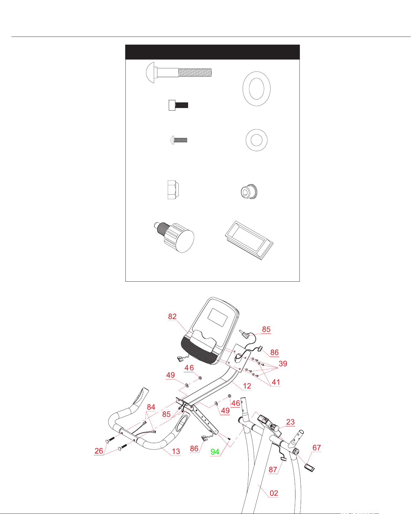
Hardware Required
#94 Screw (M5 x 10mm)
[1 piece]
#39 Screw (M4 x 12mm)
[4 pieces]
#26 Carriage Bolt (M8 x 45mm)
[2 pieces]
#41 Washer (M6)
[4 pieces]
#49 Arc Washer (M8)
[2 pieces]
BRT7989/7200 Page
Assembly STEP 6
13
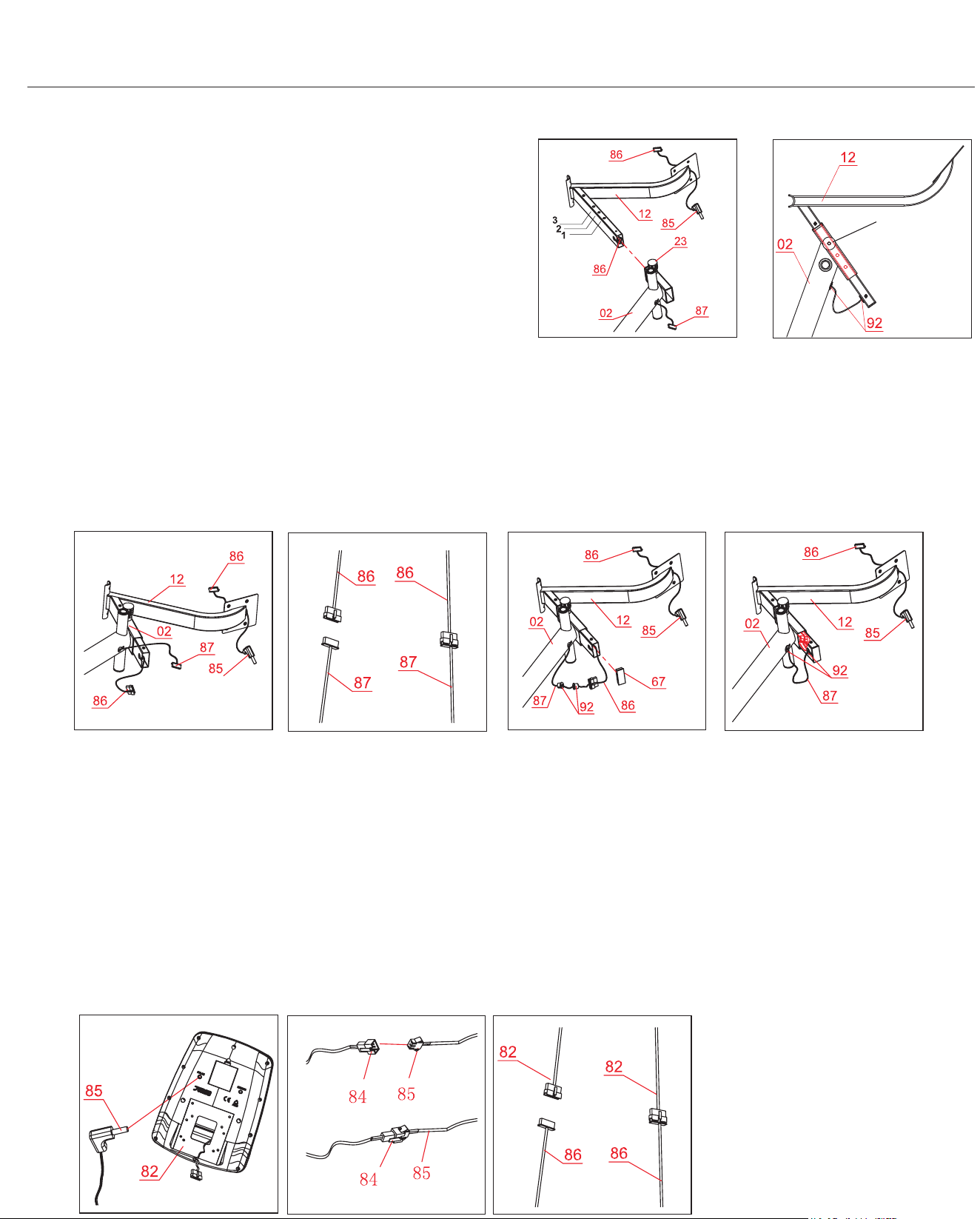
Assembly STEP 6 (Cont.)
MONITOR FRAME ASSEMBLY
Pull the Main Sensor Wire (Upper) (#86) into the Monitor Frame
(#12) as illustration 1.
Loosen the Spring Loaded Knob (#23) and pull back slightly on it so
that you may proceed to insert the Monitor Frame (#12) into the open-
ing of the post that is protruding from the Center Post (#02). Screw
in the Spring Loaded Knob (#23) through the Monitor Frame (#12)
and then through the third hole located on
the Monitor Frame (#12)
as illustration 2
.
Note: The Spring Loaded Knob (#23) has a safety feature that
allows you to loosen it by turning it cou
nter-clockwise three times as
you pull it outward. This knob can be loosened to adjust the Monitor
Frame (#12) height. Adjust the Monitor Frame (#12) height and then
release the knob back
in. Tighten the knob by turning clockwise.
Fish the Main Sensor Wire (Upper) (#86) out as illustration 3. Connect the Main Sensor Wire (Upper) (#86) to the Main Sensor Wire
After this step is completed, it will looks like the illustration 5.
To prevent the Monitor Frame (#12) from popping out off the Center Post (#02), secure the Monitor Frame (#12) using one screw (#94).
.
PULSE HANDLEBAR ASSEMBLY
Install the Pulse Handle Bar (#13) onto the bracket of the Monitor Frame (#12) using two Carriage Bolts (#26), two
Arc Washers
(#49) and two Nylon Nuts (#46). Please ensure the Pulse Sensor (#84)
is free and clear, avoiding pinching it during this assembly
step. You will need to connect this wire to the Monitor (#82) later.
MONITOR ASSEMBLY
Remove the four Screws (#39) and Washers (#41) that are pre-assembled on the back of the Monitor (#82)
. Set them aside as they
will be used later in this proces
s. Attach the Monitor (#82) to the bracket on the Monitor Frame (#12) by using the four Screws (#39)
and four Washers (#41) that were previously removed.
Connect the end of Pulse Wire (#85) to the Monitor (#82) by inserting it into the back socket as illustration B.
Connect the Pulse Sensor (#84) to the Pulse Sensor Wire (#85) as illustration C.
Connect the Main Sensor Wire (Upper) (#86) to the corresponding wire on the Monitor (#82)
as illustration D.
1
A
3
5
(Middle) (#87) as illustration A. Pull the End of Main Sensor Wires into the Monitor Frame (#12) , plug in the Wire Caps (#92) and
Rectangular End Cap (#67) as illustration 4.
C
D
B
The third hole
4
2
BRT7989/7200 Page 14
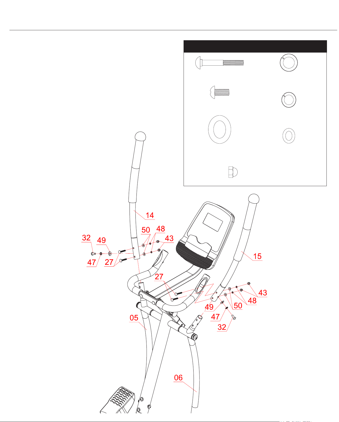
Assembly STEP 7
Hardware Required
HANDLE BAR ASSEMBLY
On the left side, insert Left Handle Bar (#14) into the opening at the
tip of Left Coupler Bar (#05). Align the holes of the Left Handle Bar
(#14) and Left Coupler Bar (#05) and secure from the side using one
Bolt (#32), one Spring Washer (#47) and one Arc Washer (#49).
Then, continue from rear/front with two Carriage Bolts (#27), two Arc
Washers (#50), two Spring Washers (#48) and two Cap Nuts (#43).
Repeat this process on the other side using Right Handle Bar (#15)
and Right Coupler Bar (#06).
#32 Bolt (M8 x 15mm)
[2 pieces]
#27 Carriage Bolt (M6 x 38mm)
[4 pieces]
#47 Spring Washer (M8)
[2 pieces]
#49 Arc Washer (M8)
[2 pieces]
#48 Spring Washer (M6)
[4 pieces]
#50 Arc Washer (M6)
[4 pieces]
#43 Cap Nut (M6)
[4 pieces]
BRT7989/7200 Page 15
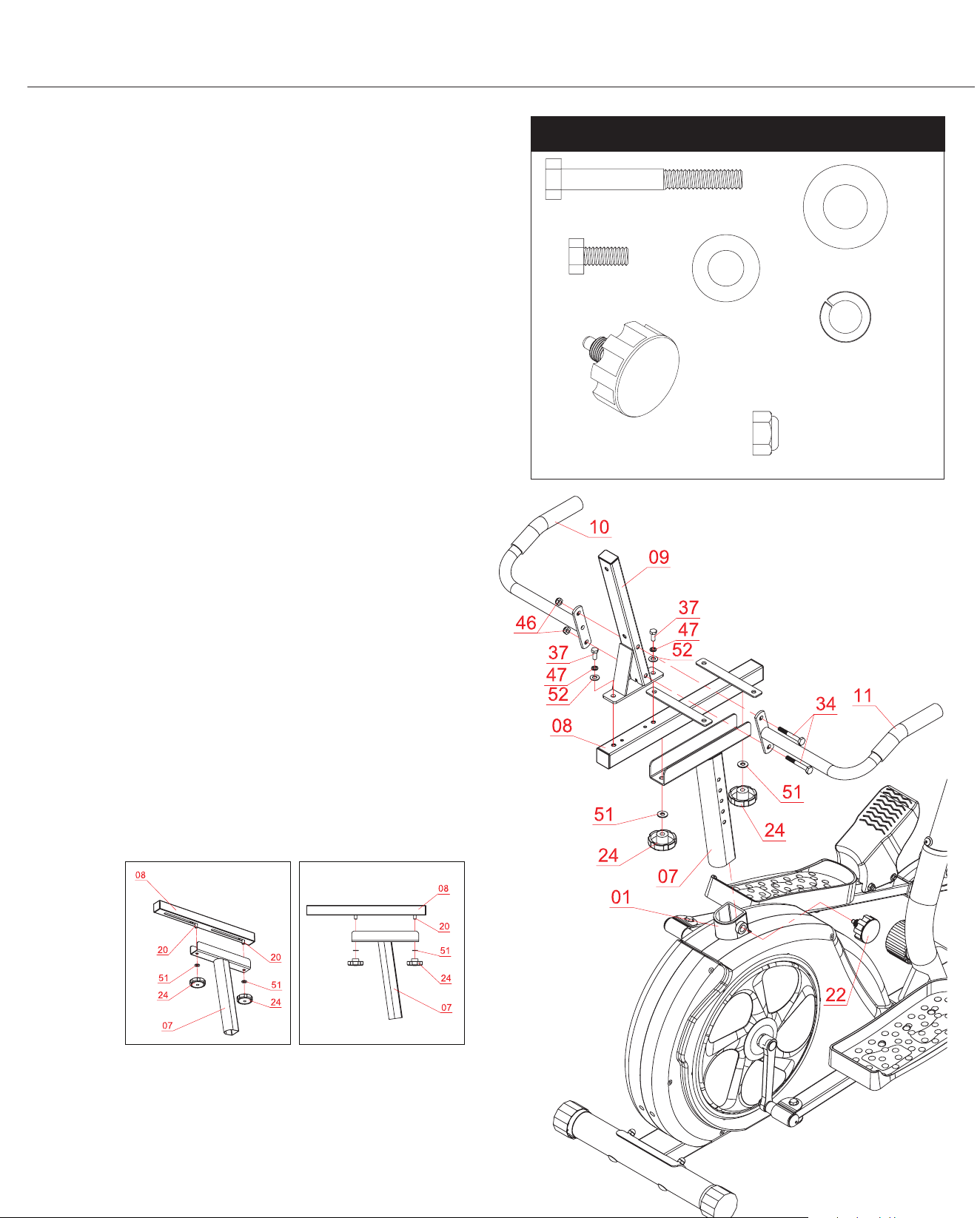
Assembly STEP 8
Hardware Required
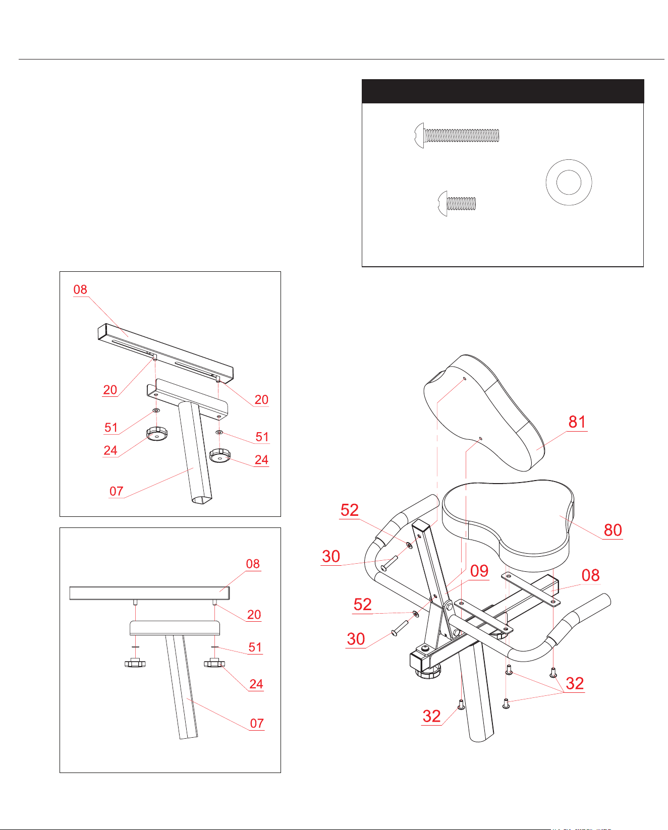
SEAT FRAME ASSEMBLY
Attach the Spring Loaded Knob (#22) to the Main Frame (#01).
Loosen the Spring Loaded Knob (#22) and pull back slightly on
it so that you may proceed to insert the Seat Post (#07) into the
opening of the post that is protruding from the Main Frame (#01)
down a minimum of four inches so that the corresponding holes can
engage. Screw in the Spring Loaded Knob (#22) through the Main
Frame (#01) and then through any one of the holes located on the
Seat Post (#07).
Note: The Spring Loaded Knob (#22) has a safety feature that
allows you to loosen it by turning it counter-clockwise three times as
you pull it out-ward. This knob can be loosened to adjust the seat
height. Adjust the seat height and then release the knob back in.
Tighten the knob by turning clockwise.
Remove the Lock Knobs (#24) and Washers (#51) from the Seat
Cushion Frame (#08). Set them aside nearby as they will be used
later in this process.
Slide the Seat Cushion Frame (#08) onto the trough of the Seat
Post (#07) as shown below. Secure using two Lock Knobs (#24)
through two Washers (#51) that were previously removed.
Attach Backrest Cushion Frame (#09) to the Seat Cushion
Frame (#08) and secure by using two Hex Bolts (#37),
two Spring Washers (#47) and two Washers (#52).
REAR HANDLE BAR ASSEMBLY
With the help of an assistant, align the four holes of the Left Rear
Handle Bar (#10) and Right Rear Handle Bar (#11) to the holes
on the Backrest Cushion Frame (#09) and secure all using the
two Hex Bolts (#34), and two Nylon Nuts (#46).
#37 Hex Bolt (M8 x 20mm)
[2 pieces]
#34 Hex Bolt (M8 x 60mm)
[2 pieces]
#47 Spring Washer (M8)
[2 pieces]
#51 Washer (M10)
[2 pieces]
#52 Washer (M8)
[2 pieces]
#46 Nylon Nut (M8)
[2 pieces]
#22 Spring Loaded Knob (M16)
[1 piece]
BRT7989/7200 Page 16
Assembly STEP 9
Hardware Required
SEAT CUSHION ASSEMBLY
Attach the Seat Cushion (#80) to the Seat Cushion Frame (#08)
and secure from the bottom using four Bolts (#32).
BACKREST CUSHION ASSEMBLY
Attach the Backrest Cushion (#81) to the Backrest Cushion
Frame (#09) and secure using two Bolts (#30) through
two Washers (#52).
#32 Bolt (M8 x 15mm)
[4 pieces]
#30 Bolt (M8 x 45mm)
[2 pieces]
#52 Washer (M8)
[2 pieces]
BRT7989/7200 Page 17
Assembly STEP 10
Hardware Required
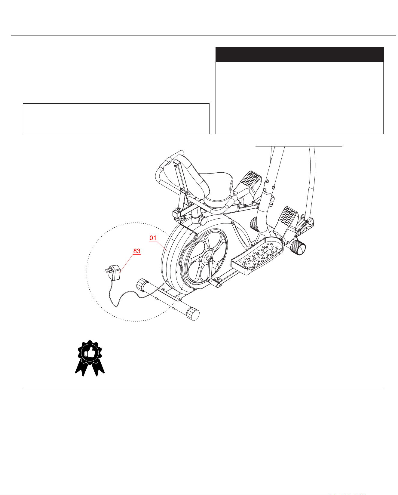
THE ASSEMBLY PROCESS IS NOW COMPLETE.
However, for your own safety, please make sure to read this entire Owner’s Manual which
includes safety instructions and warnings, as well as any safety/warning labels axed to the
product before use. For your safety , please visually and functionally inspect and test the unit
after assembly is complete.
ADAPTER ASSEMBLY
Plug in the Adapter (#83) male plug into the female socket
located at the rear end of the shroud and then plug in the
Adapter (#83) to the electrical outlet to start your workout.
No Hardware Required
NOTE :
Please wrench-tightened all parts now that assembly is completed to
ensure all nuts, bolts, and parts are tightly secured before use.
BRT7989/7200 Page 18
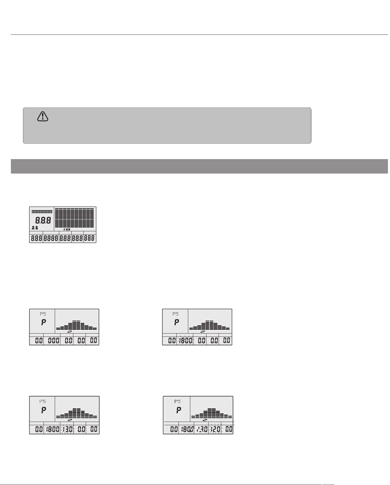
Computer Operation
Function
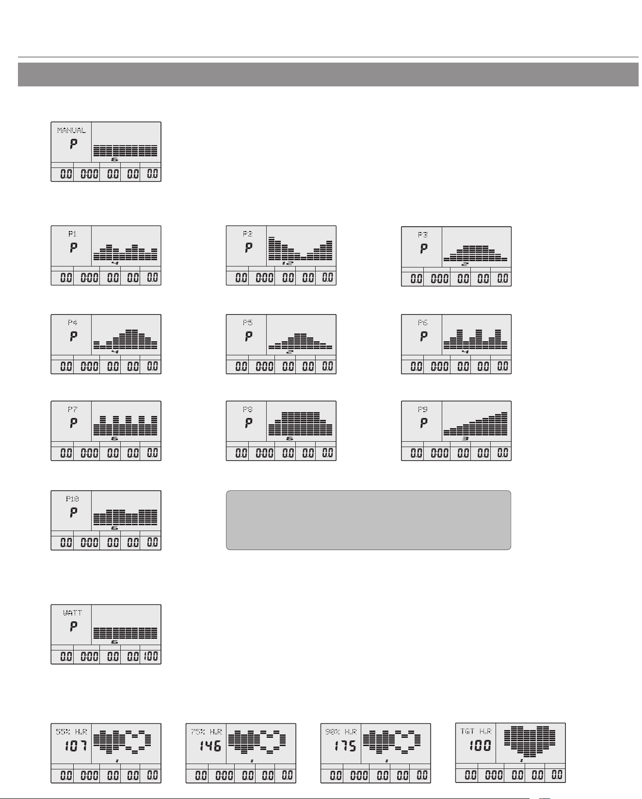
1.Program: 21 programs as following
A: 1 Manual Program (See g 1)
B: 10 Preset Program Prole: (See g 2~g 11)
C: 1 Watt Control Program (See g 12)
D: 4 Heart Rate Control Program: (See g 13 ~ g 16)
55%H.R, 75%H.R, 90%H.R and TARGET H.R
g 1
g 2
g 5
g 8
g 11
g 12
g 13 g 14 g 15 g 16
g 3
g 6
g 9
g 4
g 7
g 10
DIST.
LEVEL
ST OP
TIME CAL
WATT
M
M/H
DIST.
LEVEL
ST OP
TIME CAL
WATT
DIST.
LEVEL
ST OP
TIME CAL
WATT
DIST.
LEVEL
ST OP
TIME CAL
WATT
M
M/H
DIST.
LEVEL
ST OP
TIME CAL
WATT
M
M/H
DIST.
LEVEL
ST OP
TIME CAL
WATT
M
M/H
DIST.
LEVEL
ST OP
TIME CAL
WATT
M
M/H
DIST.
LEVEL
ST OP
TIME CAL
WATT
M
M/H
DIST.
LEVEL
ST OP
TIME CAL
WATT
M
M/H
DIST.
LEVEL
ST OP
TIME CAL
WATT
M
M/H
DIST.
LEVEL
ST OP
TIME CAL
WATT
M
M/H
P1: Rolling P2: Valley P3: Fatburn
P4: Ramp P5: Mountain P6: Interval
P7: Cardio P8: Endurance P9: Slope
P10: Rally
DIST.
LEVEL
ST OP
TIME
CAL
WATT
M
M/H
DIST.
LEVEL
ST OP
TIME CAL
WATT
M
M/H
DIST.
LEVEL
ST OP
TIME CAL
WATT
M
M/H
DIST.
LEVEL
ST OP
TIME CAL
WATT
M
M/H
DIST.
LEVEL
ST OP
TIME
CAL
WATT
M
M/H
BRT7989/7200 Page 19
Computer Operation
Button
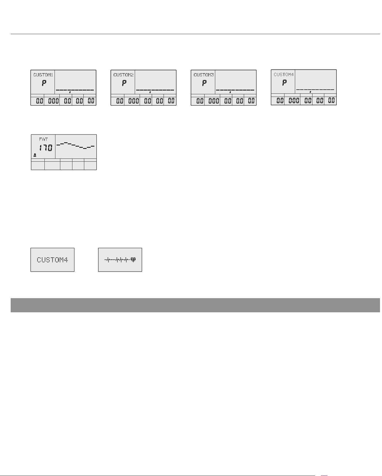
F: 1 Body Fat Measuring Program (See g 21)
1. ENTER:
● In "stop" mode(display STOP), press ENTER button to enter into program selection and setting value which ash in related window.
A: When you choose the program, press Enter to conrm the one you like.
B: When in setting, press ENTER to conrm the value that you would like to preset.
● During the start mode(display START), press ENTER to choose display the speed or RPM, or switch automatically.
2. START/STOP:
● Press START/STOP button to start or stop the programs.
● During any mode, hold down this button for 2 seconds to totally reset the computer.
3. UP:
● In stop mode and the dot matrix character ash, press this button (or rotate clockwise) to select the program up.
If the related window value ash, press this button (or rotate clockwise) to increase the value.
● During the start mode(display START), press this button (or rotate clockwise) to increase the training resistance.
4. DOWN:
● In stop mode and the dot matrix character ash, press this button (or rotate anticlockwise) to select the program down.
If the related window value ash, press this button (or rotate anticlockwise) to decrease the value.
● During the start mode(display START), press this button (or rotate anticlockwise) to decrease the training resistance.
2. Record the user's data of GENDER, HEIGHT, WEIGHT and AGE even cut o the power.
3. Dot matrix display showing your current status. (See g 22)
4. Simulative ECG measuring the heart rate (See g 23)
5. Display Speed(RPM), TIME, DIST., CAL., WATT, PULSE, LEVEL at the same time.
6. The computer will turn o automatically if there is no operation, speed signal and pulse signal over
4 minutes. Meanwhile,it will store your current exercise data and turn the loading resistance to
the minimum. Once you press any button or in motion, the computer will turn on automatically.
E: 4 User Setting Programs: CUSTOM1 to CUSTOM4 (See g 17 ~ g 20)
g 17 g 18 g 19 g 20
g 21
g 23g 22
DIST.
LEVEL
ST OP
TIME CAL
WATT
M
M/H
DIST.
LEVEL
ST OP
TIME CAL
WATT
M
M/H
DIST.
LEVEL
ST OP
TIME CAL
WATT
M
M/H
DIST.
LEVEL
ST OP
TIME CAL
WATT
M
M/H
ST OP
cm
BRT7989/7200 Page 20
Computer Operation
5. PULSE RECOVERY:
● First test your current heart rate and show your heart rate value, press this button to enter into pulse recovery testing.
● When you are in pulse recovery mode, press this button to exit.
6. RESET (IF HAVE)
● When in setting, press RESET to reset the value that you would like to preset.
● During any mode, hold down this button for 2 seconds to totally reset the computer.
1. Turn on the computer
Plug in one end of the adaptor to the AC electrical source and connect the other end to the computer. The computer will beep and
enter into initial mode.(See g 24)
2. Program select and value setting
● Manual Program and Preset Program P1 - P10
A. Press(or rotate) UP, DOWN button to select the program that you like. (See g 25)
B. Press ENTER button to conrm the selected program and enter time setting window.
C. The time will ash, and then press(or rotate) UP, DOWN button to set up your desired time.
Press ENTER to conrm the value. (See g 26)
D. The distance will ash, and then press(or rotate) UP, DOWN button to set up the desired distance value.
Press ENTER to conrm the value. (See g 27)
E. The calories will ash, and then press(or rotate) UP, DOWN to set up the desired calories to be burnt.
Press ENTER to conrm the value. (See g 28)
NOTE:
1. To press or rotate of UP, DOWN button should be followed by dierent model.
2. It is suggested to cover your nger within the marked region to select functions in case
of any wrong action.
Operation
DIST.
KM
RPM KM/H
LEVEL
START STOP
PULSE
%
YEAR
cm in
Kg lb
TIME BMR CAL BMI
WATT BODY
g 24
g 25
g 27
g 26
g 28
DIST.
LEVEL
ST OP
TIME CAL
WATT
M
M/H
DIST.
LEVEL
ST OP
TIME C AL
WATT
M
M/H
DIST.
LEVEL
ST OP
TIME CAL
WATT
M
M/H
DIST.
LEVEL
ST OP
TIME CAL
WATT
M
M/H
BRT7989/7200 Page 21
Computer Operation
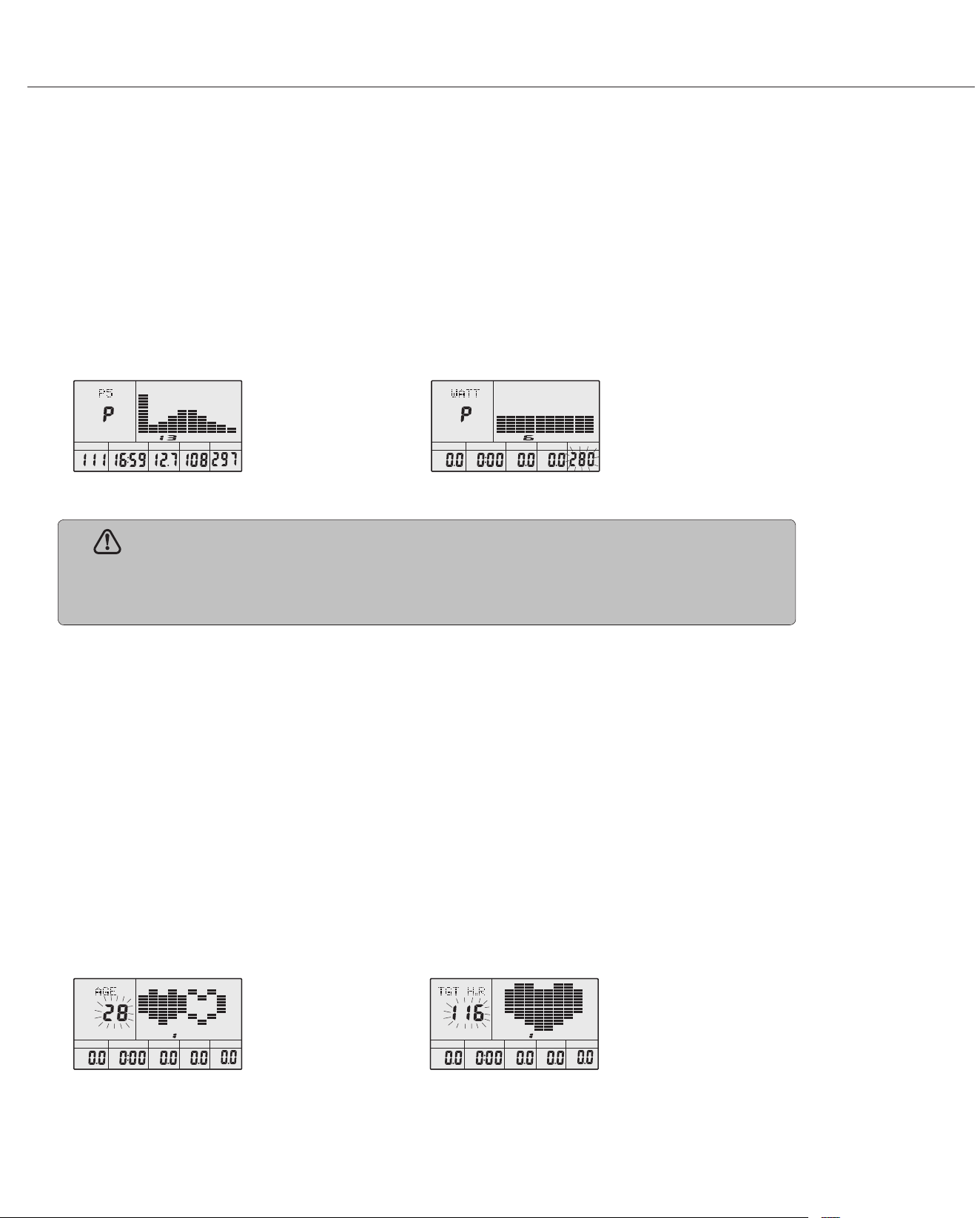
F. Press START/ STOP to begin exercise.(See g 29)
● Watt Control Program
A. Press(or rotate) UP, DOWN to select the watt control program.
B. Press ENTER to conrm the selected watt control program and enter into time setting window.
C. The time will ash, and then press(or rotate) UP, DOWN button to set up the desired time.
Press ENTER to conrm the value.
D. The distance will ash, and then press(or rotate) UP, DOWN button to set up the desired distance value.
Press ENTER to conrm the value.
E. The calories will ash, and then press(or rotate) UP, DOWN button to set up the desired calories to be burnt.
Press ENTER to conrm the value.
F. The watt display will ash, and then press(or rotate) UP, DOWN button to set up the watt to do the exercise.
Press ENTER to conrm the value. (See g 30)
G. Press START/ STOP to begin exercise.
● HEART RATE CONTROL PROGRAM: 55%H.R, 75% H.R and 90% H.R
The maximum heart rate depends on dierent age and this program will ensure you do the healthy exercise within
maximum heart rate.
A. Press(or rotate) UP, DOWN button to choose the heart rate control program.
B. Press ENTER to conrm the heart rate control program and enter into time setting window.
C. The time will ash, and then press(or rotate) UP, DOWN button to set up the desired time.
Press ENTER to conrm the value.
D. The distance will ash, and then press(or rotate) UP, DOWN button to set up the desired distance value.
Press ENTER to conrm the value.
E. The calories will ash, and then press(or rotate) UP, DOWN button to set up the desired calories to be burnt.
Press ENTER to conrm the value.
F. The age will ash, and then press(or rotate) UP, DOWN button to set the user's age.
Press ENTER to conrm the value.(See g 31)
G. When the target heart rate control program ash, the computer will display the user's target heart rate according
to user's age, heart rate according to user's age.
H. Press START/ STOP to begin exercise.
g 29
g 31
g 30
g 32
DIST.
LEVEL
ST OP
TIME CAL
WATT
M
M/H
DIST.
LEVEL
STAR T
TIME
CAL
WATT
RPM
M
NOTE:
The WATT value is decided by the TORQUE and RPM. In this program, the WATT
value will keep at constant value. It means that if you peddle quickly, the load resistance will
decrease and if you peddle slowly, the load resistance will increase to ensure you at the same
watt value.
DIST.
LEVEL
ST OP
TIME CAL
WATT
M
M/H
DIST.
LEVEL
ST OP
TIME CAL
WATT
YEAR
M
M/H
BRT7989/7200 Page 22
Computer Operation
● HEART RATE CONTROL PROGRAM: TARGET HEART RATE
The user can set any target heart rate to do the exercise.
A. Press(or rotate) UP, DOWN button to select TARGET HEART RATE program.
B. Press ENTER to conrm your choice and enter time setting window.
C. The time display will ash, and then press(or rotate) UP, DOWN button to set the desired time to do the exercise.
Press ENTER to conrm the value.
D. The distance will ash, and then press(or rotate) UP, DOWN button to set up the desired distance value.
Press ENTER to conrm the value.
E. The calories will ash, and then press(or rotate) UP, DOWN button to set up the desired calories to be burnt.
Press ENTER to conrm the value.
F. The target heart rate will ash, and then press(or rotate) UP, DOWN button to set up your target heart rate.
Press ENTER to conrm the value.(See g 32)
G. Press START/ STOP to begin exercise.
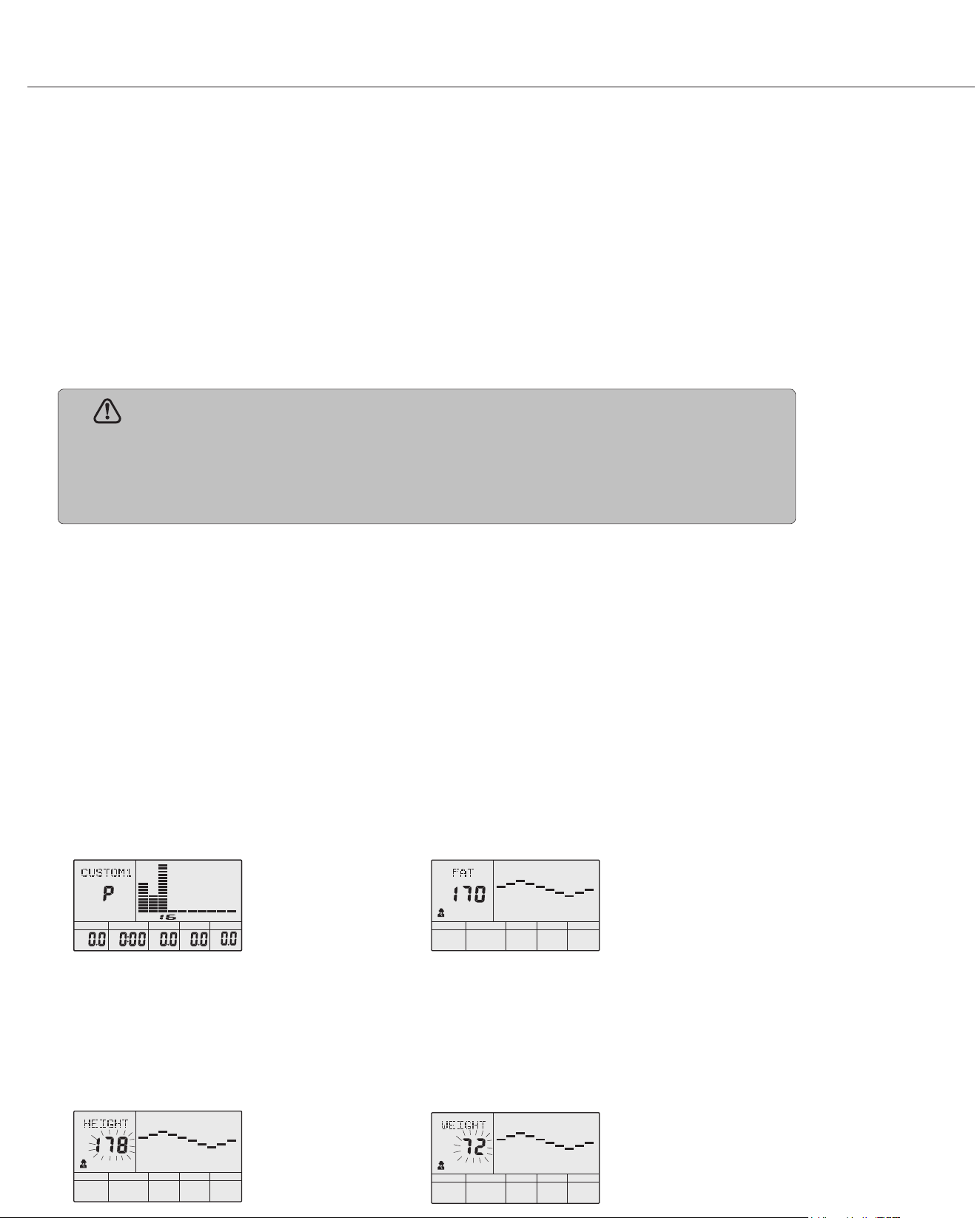
● User Prole Programs: CUSTOM1- CUSTOM4
A. Press(or rotate) UP, DOWN button to select the user.
B. Press ENTER to conrm your choice and enter into time setting window.
C. The time display will ash, and then press(or rotate) UP, DOWN button to set up the desired time to do the exercise.
Press ENTER to conrm the value.
D. The distance will ash, and then press(or rotate) UP, DOWN button to set up the desired distance value.
Press ENTER to conrm the value.
E. The calories will ash, and then press(or rotate) UP, DOWN button to set up the desired calories to be burnt.
Press ENTER to conrm the value.
F. The rst resistance level will ash, and then press(or rotate) UP, DOWN button to set the desired load resistance.
Press ENTER to conrm. Then repeat the operation to set the resistance from 2 to 10. (See g 33)
G. Press START/ STOP to begin exercise.
● Body Fat Measurement Program
A. Press(or rotate) UP, DOWN button to select BODY FAT TEST program (See g 34)
B. Press ENTER to conrm your choice, and enter into height setting mode
C. The height display will ash, and then press(or rotate) UP, DOWN button to set up your height.
Press ENTER to conrm the value.(See g 35)
D. The weight display will ash, and then press(or rotate) UP, DOWN button to set up your weight.
Press ENTER to conrm the value.(See g 36)
g 33
g 35
g 34
g 36
NOTE:
During exercise, the user's heart rate value depends on resistance level and speed. The
heart rate control program is to ensure your heart rate within the preset value. When the
computer detect your current heart rate is higher than preset, it will decrease the resistance
level automatically or you may slow down exercise. If your current heart rate is lower than
preset, it will increase resistance and you may speed up.
ST OP
cm
DIST.
LEVEL
ST OP
TIME CAL
WATT
M
M/H
ST OP
Kg
ST OP
cm
BRT7989/7200 Page 23
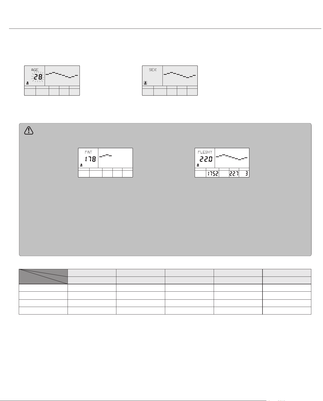
E. The age display will ash, and then press(or rotate) UP, DOWN button to set up your age.
Press ENTER to conrm the value.(See g 37)
F. The gender display will ash, and then press(or rotate) UP, DOWN button to set up your gender.
Press ENTER to conrm.(See g 38)
G. Press START/STOP to begin testing your body fat. (See g 39)
g 37 g 38
NOTE:
1. During the body fat measurement, place both your palms on the contact pads. The test result are: FAT%,
BMR(Basal Metabolic Rate), BMI(Body Mass Index), BODY and body shape.(See g 40)
FAT%: The total body fat in our body measured by percentage.
BMR: Basal Metabolic Rate (metabolism) is the energy (measured in calories) expended by the body at rest to
maintain normal bodily function.
BMI: means Body Mass Index, which is used for body shape building
2. During the body fat measurement, if your palms do not contact the pulse sensor well, the computer cannot
receive any signal and it will display ERROR2. Press START/STOP to try again.
3. During the test, you cannot exit the test when press any button. After the test nish, press (or rotate) UP,
DOWN button to exit the body fat measurement program and switch to other program.
4. Comparison sheet of Body fat and Obese
Computer Operation
ST OP
YEAR
ST OP
ST OP
BMR BMI
BODY
%
STAR T
cm
g 39 g 40
Slim Healthy Slightly Overweight Overweight Obese
Body1 Body2 Body3 Body4 Body5
Male/≤30 years old <14% 14%~20% 20. 1%~25% 25. 1%~35% >35%
Male/>30 years old <17% 17%~23% 23. 1%~28% 28. 1%~38% >38%
Female/≤30 years old < 17% 17%~24% 24. 1%~30% 30. 1%~40% >40%
Female/>30 years old <20% 20%~27% 25. 1%~33% 23. 1%~43% >43%
Body Shape
FAT%
Age/Gender
BRT7989/7200 Page 24
Computer Operation
3. Pulse Recovery Test
The pulse recovery test is to compare your heart rate before and after exercise. It is target to
determine your heart strength via the measuring. Please do the test as below:
A. Both your hands hold the pulse sensor or via wireless transmitter belt to test the pulse(if applicable), the computer will display your
current pulse value.
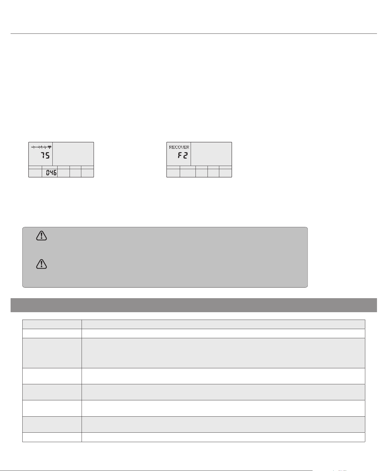
B. Press RECOVERY to enter the pulse recovery test and the computer program will enter the stop status.(See g 41)
C. Keep pulse detecting.
D. Time will count down from 60 seconds to 0 second.
E. When time reaches 0, the test result (F1-F6) appears on the display.
F1 = Excellent F2 = Good F3 = Fair F4 = below average F5 = No Good F6 = Poor (See g 42)
F. If the computer does not detect your current heart rate rst, pressing RECOVERY will not enter into pulse recovery test.
During the pulse recovery test, press RECOVERY to exit the test and return to the stop status.
Speed (M/H) showing your current speed. Range: 0.0~99.9 (M/H)
RPM showing the current rotate per minute. Range : 0(999
TIME: the accumulative exercise time, range : 0:00~99M59S. The preset time range is 5:00~99M00S.
The computer will start to count down from preset time to 0:00 with average time for each resistance level.
When it reaches to zero, the program will stop and computer alarm. If you do not preset the time, it will run
with one minute decrement each resistance level
DIST the exercise accumulative distance. Range : 0.0~99.9~ 999 (MILE) the preset distance range :1.0~99.0~999.
When the distance reaches 0, the program will stop and the computer will alarm
CALORIE the exercise accumulative calories burnt. Range : 0.0~99.9~999 the preset calories range :10.0~90.0~990.
When the calorie reaches 0, the program will stop and the computer will alarm
PULSE showing the exercise heart rate value.
Range: 30~240 bpm (beat per minute)
RESISTANCE
LEVEL
showing resistance level.
Range:1~16
WATT show the exercise watt
4. Pulse Measurement
Please place both your palms on the contact pads and the computer will show your current heart
beat rate in beats per minute (BPM) on the LCD after 3~4 seconds. During the measurement, heart
icon will ash with simulative ECG showing.
g 41 g 42
REMARK:
During the process of pulse measurement, because of the contact jamming, the
measurement value may not be stable when start, then it will return to normal level. The
measurement value cannot be regarded as the basis of medical treatment.
NOTE:
If the computer is also equipped with wireless heart rate measuring via the transmitter
belt, and with hand pulse function, the hand-measurement-signal-detecting is preferred.
ST OPST OP
PULSE
TIME
Specications

BRT7989/7200 Page 25
Computer Operation
1. When the computer displays ERROR1, please check if the motor is good and if the motor wires connect well.
2. When the computer displays ERROR2, please check if your hands contact the sensors well as there no body fat signal detected.
INPUT: AC220V (The voltage depends on dierent country)
OUTPUT:
Display Error
Adaptor
NOTES (Regarding the Computer Monitor):
Warning: This device complies with Part 15 of the FCC Rules. Operation is subject to the following two conditions:
(1) This device may not cause harmful interference.
(2) This device must accept any interference received, including interference that may cause undesired operation.
Caution:
This equipment has been tested and found to comply with the limits for a Class B digital device, pursuant to part 15 of the FCC Rules.
These limits are designed to provide reasonable protection against harmful interference in a residential installation. This equipment generates, uses and
can radiate radio frequency energy and, if not installed and used in accordance with the instructions, may cause harmful interference to radio
communications. However, there is no guarantee that interference will not occur in a particular installation. If this equipment does cause harmful
interference to radio or television reception, which can be determined by turning the equipment o and on, the user is encouraged to try to correct the
interference by one or more of the following measures:
- Reorient or relocate the receiving antenna.
- Increase the separation between the equipment and receiver.
- Connect the equipment into an outlet on a circuit dierent from that to which the receiver is connected.
- Consult the dealer or an experienced radio/TV technician for help.
DC 8V/600mA

BRT7989/7200 Page 26
Troubleshooting
If the computer is not displaying the CALORIES/DISTANCE/TIME/(ETC.) functions
(or you are getting inaccurate readings), please adjust
the following:
1. Check to ensure all computer sensor wires are properly
connected and are not damaged.
2. You may need to refer to installation/assembly directions for the sensor wires in
this manual.
If the computer display is blank & not displaying any data (or does not appear to
power on), please adjust the following:
1. Check to ensure all sensor wires are all properly connected and are not dam-
aged.
2. Check to ensure the AC Adapter* or Batteries* are properly plugged in or fully
charged.
3. Check your product manual to determine if your model uses either AC Adapter or
batteries to power your unit.
If the computer is not picking up your hand pulse signal (or you are getting inaccurate
readings), please adjust the following:
1. Slightly moisten/dampen the palms with water so the sensors can detect a pulse
signal.
2. Do not grip the sensors too tightly. Only moderate pressure need be applied.
3. Gripping the sensors too tightly restricts and seizes detection of your pulse.
4. Remove any rings or jewelry to prevent interference.
5. Check to ensure all pulse sensor wires are properly connected and are not dam-
aged.
6. You may need to refer to installation/assembly directions for the pulse sensor
wires in this manual.
(AFTER COMPLETE ASSEMBLY)
Troubleshoot Area
Calories/Distance/
Time (Etc.)
Computer Display
Hand Pulse Signal
Computer Error Code Guide
***Note: If there are more than one error that exists with the unit, user will see all the error codes display in alteration
For your safety, please do not discard this Troubleshooting sheet or the Owner’s Manual, and keep them in a place where you can easily access/
refer to them at any time. If you are still having any troubleshooting issues, please contact our Customer Support for further assistance.
Solution
Error Code Description Possible Reason Inspection Resolution
No Code No updates for the workout matrix
values on computer display during
exercise
(1) No sensor connectivity Check if sensor malfunction or sensor
position shifted
Replace sensor or reposition sensor to the
correct location
(2) Wiring or connection issue Check if sensor wire is broken or lose
connection
Reconnect or replace sensor wiring
E1 Motor Related Issues (1) Defective motor Check if motor damaged Replace motor
(2) Magnetic control system malfunction Check if magnetic control system is
damaged
Adjust or replace magnetic control system
(3) Bad wiring or connectivity issue Check for wire damage or loose con-
nection
Reconnect or replace motor wiring
E2 Heart Rate not detected by the
pulse-sensor on handlebar
(1) Hand position on grip is placed incor-
rectly
Check if hand is placed on the grip
correctly
Check wire connectivity rst, if issue
persist, then replace pulse sensor and/or wiring
(2) Pulse sensor malfunction Check pulse sensor wiring and
connection
Reconnect or replace hand grip pulse sensor
wiring
E3 Computer Internal Error Computer component issue Check computer wire connection Replace computer and/or wiring

BRT7989/7200 Page 27
Safety and Maintenance
• Make sure all nuts, bolts, and screws are tightened prior to use.
• Be sure that all adjustment locking devices and safety devices are properly engaged prior to use!
• Never over-tighten the above-mentioned devices and parts to avoid damage to the unit.
• Check for loose parts and components and make proper adjustments prior to use.
• Check to see if there are any tears or bends in the welding or metal prior to use. If tears or bends are found,
DO NOT use the unit and contact our CUSTOMER SUPPORT.
• Extreme care must be taken to not allow your feet, ngers, hair, clothing, and/or any loose items to be snagged into
any portion of the bike when the unit is in motion. Failure to follow these instructions could result in serious injury,
including the loss of ngers.
• Always wait for the pedals and other moving parts (which can gain great momentum during riding) to come to a
complete stop before dismounting the unit to avoid serious injury.
NOTE: Always wait for the pedals and/or any other moving parts (which can gain great momentum during riding)
to come to a complete stop before dismounting the unit to avoid serious injury.
• To reduce speed on the bike, you may use the combinations of your feet on the Left/Right Pedals (#57/#58) and your
hands on the Left/Right Handlebars (#14/#15) to gently and safely apply counter-momentum.
• Wait for the pedals to come to a complete stop.
• Now you may safely dismount the unit
NOTE:
To safely move, transport, and/or store the unit, please seek the help of capable assistants (minimum of 2 people).
The unit has integrated Front Rollers purposely intended to help ease this process.
• Position one person on each side at the front of the bike toward the handle Bar
(one person on the left, and one on the right).
• Have each person use both hands to grip the corresponding Pulse Handle Bar (#13).
(These are the safest areas to avoid injury during this process.)
• Have both people simultaneously lift the rear end of the unit, leaving the weight and pressure into the front of the unit
and onto the Front Rollers to move/transport the unit to the desired area.
• Please review all safety instructions and warnings in this entire Owner’s Manual, as well as any safety/warning labels
axed to the product before use.
• Do not use solvent cleaners. If you are in any doubt, do not use your cleansing product; contact
CUSTOMER SUPPORT.
• The specic parts on your unit which may see possible signs of wear after prolonged use are listed as follows
(please check these parts before each use):
Foot Pedals (#59/#60); Left/Right Handlebars (#14/#15).
• For any replacement warning labels, please contact our CUSTOMER SUPPORT at
1 (888) 266-6789 or 1 (909) 598-9876, or mail in a written request to:
Body Flex Sports, Inc.
21717 Ferrero Parkway
Walnut, CA 91789
More detailed information about how to reach our CUSTOMER SUPPORT may be found on Page 2 of the
Owner’s Manual under the “CUSTOMER SUPPORT” section.
Safety & Warning
How To (Emergency) Stop
How To Move/Transport The Bike For
Maintenance & Care
BRT7989/7200 Page 28
Warm-Up Instructions
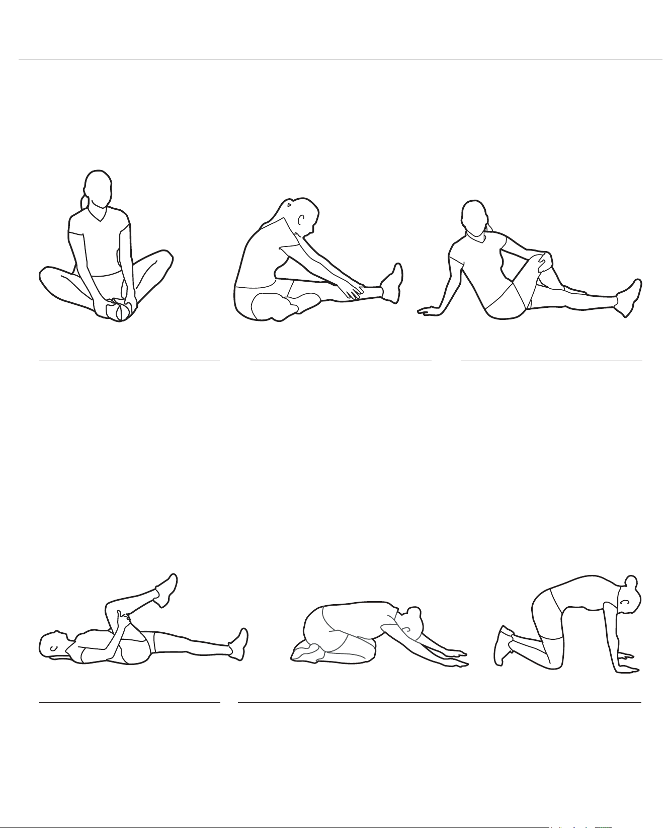
1. Sit with your knees exed and
soles of feet together.
2. Hold your ankles and bend
at your hips (keep your back
straight) as you press your
knees toward the oor with your
elbows.
1. Lie on your back and raise
your right leg as you clasp both
hands under the back of the
knee. Keep your left leg straight.
2. Gently pull your right leg toward
your trunk without
raising your upper body. Switch
leg positions and repeat.
1. Sit with your left leg extended
and bend your right leg at the
knee as you place the sole of
your right foot against the inner
thigh of your extended leg.
2. Flex the foot of your extended
leg (toes pointed toward
ceiling) and gently bend forward
from your hips; keep your back
straight.
3. Reach your hands on your
extended leg as far as possible
and then switch legs and repeat.
1. Assume the depicted position on your hands and knees. Stretch your
hands out in front of you and then slowly start to pull them back in toward
your body as you tuck your chin and arch your back upward.
2. Return to the starting position slowly.
1. Sit with your leg extended and
bend your right knee as you
cross your right leg over your
left leg. Your right foot of your
extended leg foot should be at
on the oor alongside your left
knee.
2. Place your left arm on the
outside of your right leg and pull
against that leg while twisting
your trunk as far as possible to
the right. Place your right hand
on the oor behind your but-
tocks. Reverse leg positions and
repeat.
Before use, you must read and understand all instructions & warnings stated in this Owner’s Manual as well as posted
on the equipment. Before beginning any exercise program including the following exibility exercises, please consult with
your physician.
The following exibility exercises are provided to you as a means to prevent injury while you are exercising. A proper
warm-up routine decreases the chance of injuring your muscles while you are exercising. Please take the time to do these
exibility exercises before and after each time you exercise.
Groin Stretch
Groin Stretch
Hamstring Stretch
Trunk Flexion, Prone
Trunk Twister
BRT7989/7200 Page 29
Warm-Up Instructions
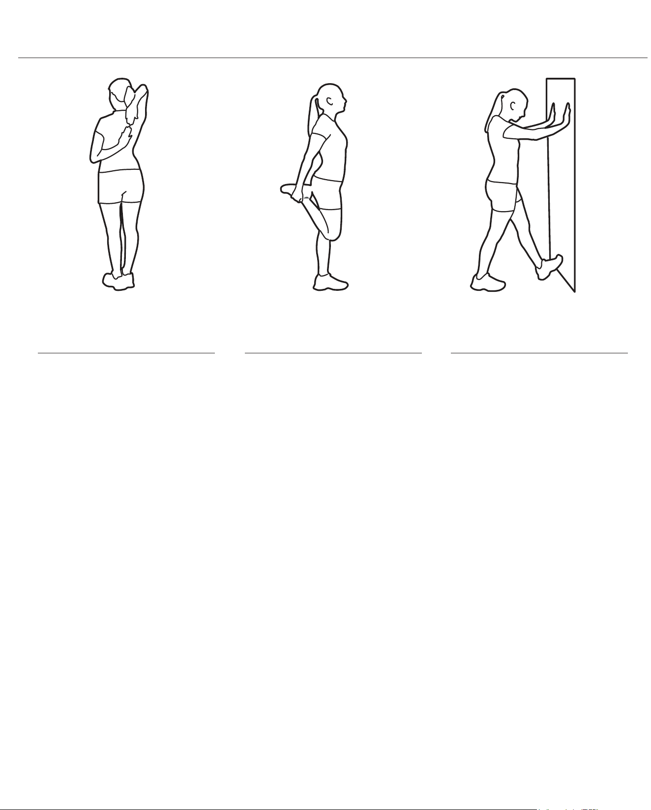
1. Bring your right hand over your
right shoulder to the
upper back and bring your left
hand under your left shoulder to
the upper back.
2. Try to reach your ngertips. If
you are not able to reach your
ngertips, use a towel as an
extension of your hands and
gently pull one hand toward the
other.
Reverse arm positions and
1. Stand on your left leg and hold
onto a support with your left
hand.
2. Flex your right leg behind you,
grasp your ankle or foot with
your right hand and pull your
foot toward your buttocks. Keep
your back straight and right
knee pointed down.
Repeat on the other leg.
1. Place both hands against a wall
to aid your balance. Press the
ball of your left foot against the
wall and keep the heel of the
same foot rested on the oor
(make sure your left knee is
bent).
2. Slowly start to straighten your
left knee and you will feel the
muscles in your left calf stretch.
Switch leg positions and repeat.
Shoulder Stretch Quadriceps Stretch Calf Twister

THANK YOU FOR YOUR PURCHASE
MODEL NO.: BRT7989/BRT7200
along with your sales receipt as proof of purchase.
Serial Number :
Date of Purchase :
Retailer :
Body Flex Sports, Inc.
21717 Ferrero Parkway
Walnut, CA 91789
Phone
: 1 (888) 266-6789
Fax : 1 (909) 598-6707
Email
Ver. 08/17/2019 Printed in China