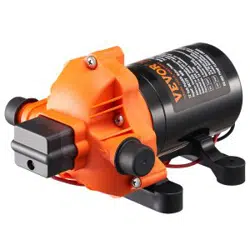

Diaphragm Pump
Instruction Manual
01
Diaphragm Pump
Have product questions? Need technical suppo?
Please feel free to contact us:
CustomerSe[email protected]
NEED HELP? CONTACT US!
This is the original instruction,Please read all manual instructions carefully
before operating.VEVOR resees clear interpretation of our user manual. The
appearance of the product shall be subject to the product you
received.Please forgive us that we won't inform you again if there is any
technology or software updates on our product.
NMDP52-G55-70-12

02
PRODUCT SPECICATIONS
FEATURES
An economical workhorse, the 52 Series is engineered for exibility.
The 5-chamber series are our Heavy-Duty water pump. It provides
high-volume water ow with reduced pump cycling, thanks to the
large ve-chamber diaphragm. With the on- demand switch, 5.5
GPM, and
70
PSI, the
52
Series will meet your special requirements
with positive predictable peormance. With a built-in bypass
function, the 52 Series can reduce rapid cycling and allow water to
ow back from the outlet side to the inlet side of the pump. We also
oer a variety of easy-connect ttings and lters.
·5 -chamber diaphragm pump
·Continuous duty
·Indust-standard mounting pattern
·Run d capable for normal workloads
·Automatic: controlled by pressure switch
·Self priming
·Quiet Operation
·
An incredible feature list, high-quality components, plus amazing
peormance. The five-chamber high-volume design, driven by a
heavy-duty motor produces ow rates of 5.5 GPM, capable of
self-priming up to 6 veical feet, and can run d, making it the
price-to-peormance leader. This pump also oers a variety of
easy-connect ttings and lters.
Ignition protectedBypass: reduces cycling
Propey Specications
Rated Voltage
Rated Pressure
Max. Flow
Inlet/Outlet Diameter
Number of Chamber 5 PCS
12V
70 PSI
5 PCS
5.5 GPM
1/2" MNPT

APPLICATIONS
INSTALLATION
03
·Yacht/RV/caravan pressurized water system
·Sprayer xtures (vehicle-mounted sprayers,electric sprayers)
·Cleaning machines Humidiers water purication,medical apparatus
·Food beverage lling & liquid transfer
·Solar water system
·Any other pressurization system
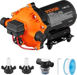
1.diaphragm pump with related accessories
2.(at least) pieces of exible, reinforced hose piping, with collapsing
strength of twice the inlet collapsing pressure(hose must be
minimum 1/2"ID)
3.stainless steel hose clamps and screws
4.screws to fasten the pump to the mounting suace
1 electrical cut o switch
1 fuse
1 screwdriver
1 strong cutting implement for tubing (if desired)Teon tape or sealant
1. The pump may be mounted in any position. If mounted veically,
the pump head should be in the down position to avoid leakage into
the motor casing in the event of a malfunction.
2. Secure the feet, but do not compress them. Over tightening the
securing screws may reduce their ability to dissipate noise and
vibration.
3.The inlet and outlet hoses must be 1/2" (13 mm) ID reinforced
hoses. The diameter of branch and individual supply lines from the
outlet should be no smaller than 3/8" (10 mm).
4. Plumb the system using high pressure (2 x pump rating), braided,
exible tubing to minimize vibration/noise.
5.Do not apply inlet pressure in excess of 30psi. In general, t to
avoid any inlet pressure completely.
6.Avoid any kinks or ttings which could ca use excessive restric-
tions.
7.Strainer should be attached to the inlet side.
8.The ttings must be secured to avoid leakage
9.Use clamps at both ends of the hose to prevent air leaks into the
water line.
10. If a check valve is installed in the plumbing, it must have a
cracking pressure of no more than 2 psi. 11. If applying a sealer or
plumbing tape, be careful to not over tighten, as they may be
sucked into
Materials
Setup

04
12. This pump should be wired on its own dedicated circuit. Connect
the positive lead (red) to the positive
terminal of your batte and the negative wire(black) to the
negative terminal of your batte.
13. In an easily accessible location, install a switch to control
electricity to the pump. Turn the pump o when
not used for extended periods or when the tank is empty.
14. The electrical circuit should be protected with an over-current
protection device(fuse) in the positive
lead. This pump requires a 15 amp fuse.
15. The pump circuit should not include any other electrical loads.
16. As the water supply pump is non-essential, reference the wire
Cha under the electrical information. Be
sure to have the correct wire sizing for the length of wire you are
using.
17.After installation, check the voltage at the pump motor. Voltage
should be checked when the pump is operating. Full voltage must
be available at the pump motor at times.
1. Flexible potable water hose or PEX tubing is recommended
instead of rigid piping at the pump. If you choose to use rigid piping,
provide a sho length of hose between the pipe and the pump to
avoid noise and vibration.
2. We do not recommend the use of metal ttings. When possible,
use the provided plastic ttings.
3. Do not adjust the bypass personally without the help of a
technician.
4. Lack of sanitizing and maintenance is one of the main reasons for
the underpeormance of the pump. Please do maintenance and
winterize the pump at appropriate times, especially before and after
a period of storage.
Notes
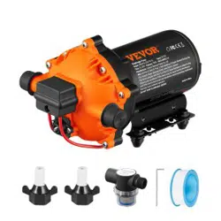
ACCESSORIES
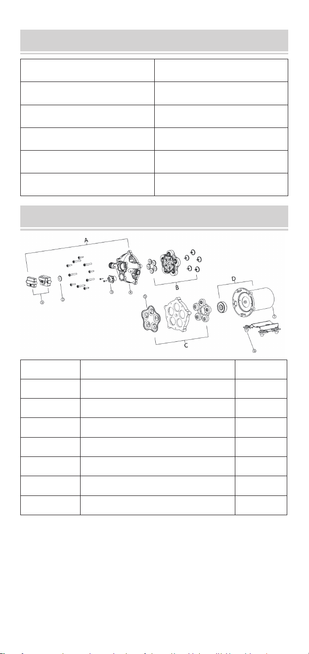
EXPLODED VIEWS
05
Item
Quantity
Hose Adapter
2
Filter
Hexagon Bolt
Sealing Tape
1
1
1
3/4" Copper Hose Adapter 1
KEY Description Quantity
1
2
3
4
5
6
7
Pressure Switch
Diaphragm of Pressure Switch
Bypass Switch
Pump Head
Diaphragm
Iron Feet Group
Motor
1
1
1
1
1
1
1
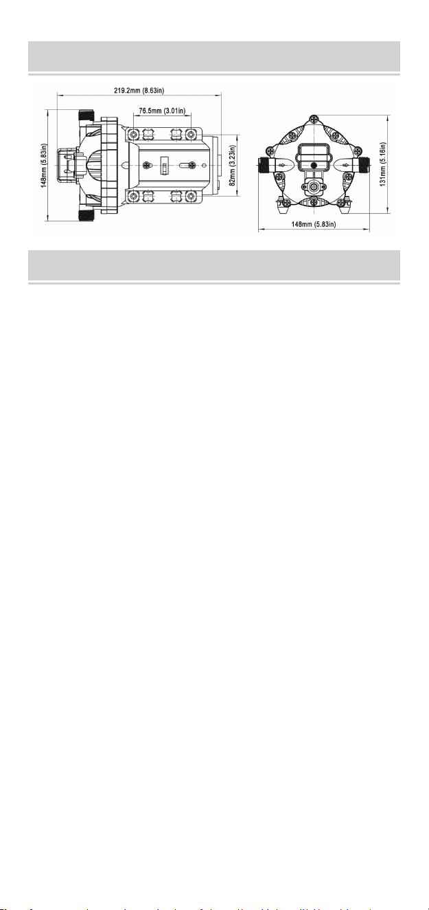
PRODUCT SIZE
TROUBLESHOOTING
06
•Check lines for kinks.
•Plumbing lines or ttings may be too small.
•Clean faucets and lters.
•Check tting tightness for air leaks.
PULSATING FLOW— PUMP CYCLES ON AND OFF
•Restricted in take or discharge line .
• Air leak in intake line.
•Punctured pump diaphragm
•The initial amp supply is not enough to suciently sta the motor.
•Debris clogs in the valves .
•Crack in the pump housing.
FAILURE TO PRIME BUT MOTOR OPERATES - NO
PUMP DISCHARGE
• Loose or improper wiring.
•The pump circuit has no power.
• Blown fuse.
•Failed pressure switch.
•Defective motor.
MOTOR FAILS TO TURN ON
• Punctured diaphragm.
•Discharge line leak
Defective pressure switch.
•Insucient voltage.
•Clogged valves in the pump head.
PUMP FAILS TO TURN OFF AFTER ALL FIXTURES ARE CLOSED
• Air leak at the pump intake.
•AccumuIation of debris inside pump or plumbing.
•Worn pump bearing (possibly accompanied by loud noise).
•Punctured diaphragm
•Defective motor.
LOW FLOW AND PRESSURE
TIP: Bypass adjustment should be peormed by a professional
technician using a proper gauge and equipment. Without the proper
equipment, you could mis-adjust the valve or switch causing the
pump to work improperly (see Caution below).
About the Bypass Valve
The pump uses a spring-loaded bypass valve to maintain smooth
peormance as water demands rise and fall. When a faucet is
turned on the pump is providing full water ow, so the bypass valve
is closed. But when there is little to no water demand, the bypass
valve opens to allow water to ow back from the outlet side to the
inlet side, keeping a steady ow of water within the pump with
almost no cycling.
USE THE FOLLOWING PROCESS TO ADJUST SHUT-OFF AND
BY-PASS PRESSURES
ADJUSTING THE BYPASS VALVE AND PRESSURE SWITCH
07
• Check if the mounting feet are compressed too tightly.
•ls the mounting suace exible? If so, it may be adding noise.
•Check for loose head/screws.
•If the pump is plumbed with rigid pipe,then it may transmit noise
more easily.
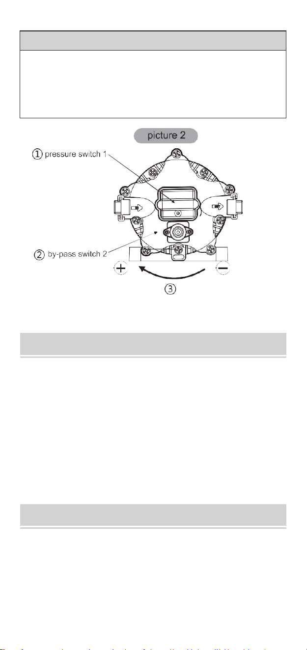
ADJUSTING THE PUMP'S SHUT-OFF PRESSURE:(1)
● To raise the shut-o pressure, use a 2mm Allen wrench to turn
the pressure switch screw clockwise to the desired pressure.
●To lower the shut-o pressure, use a 2mm Allen
wrench to turn the pressure switch screw counter-clockwise to the
desired pressure.
ADJUSTING THE BYPASS:(2)
●To raise the pressure at which the bypass stas and raise the full
bypass pressure, use a 2mm Allen wrench to turn the bypass screw
clockwise to the desired pressure.
●To lower the pressure at which the bypass stas and lower the
full bypass pressure, use a 2mm Allen wrench to turn the bypass
screw counter-clockwise to the desired pressure.
NOISY
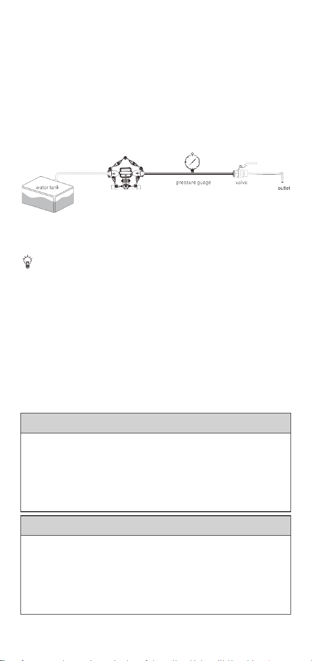
1. Install the pump as in picture 1.
08
CAUTION:
The pressure setting for full bypass must be at least 8psi higher than
the shut-o pressure of the pump. If the switch and bypass is
adjusted too closely, the bypass and switch shut-o can overlap and
the pump will not shut o.
ABOUT THE BYPASS
CAUTION
Please consult a professional technician in case the bypass needs
adjustment. Improper adjustment of the bypass may damage the
pump.
The bypass comes preset for optimal operation of the pump. If your
application calls for a dierent setting for the bypass, you may
change it yourself. Carefully tighten the screw to increase or loosen
the screw to decrease the minimum operating pressure of the
bypass.
Please do follow the instruction manual to install the product. Any
action outside what is recommended in this manual may bring
damage to the pump. Any inappropriate installation or operation
that causes the pump damage is not covered by warranty.

FCC INFORMATION
09
This device complies with Pa 15 of the FCC Rules. Operation is
subject to the following two conditions:(1)This device may not cause
harmful inteerence, and (2)thisdevice must accept any inteerenc
ereceived , including inteerence that may cause undesired
operation.
This product is subject to the provision of European Directive
2012/19/EC. The symbol showing a wheelie bin crossed through
indicates that the product requires separate refuse collection in the
European Union. This applies to the product and all accessories
marked with this symbol. Products marked as such may not be
discarded with normal domestic waste, but must be taken to a
collection point for recycling electrical and electronic devices
*There are any minor changes to the numbers included in the user
manual without prior notice.
Manufacturer: Xiamen Newmao Pump Co., Ltd
Add:2nd Pak of Zone Ⅲ, Floor 3, Main Building of Huaxin General
Facto;, No. 216, Huanzhu Road, Qiaoying Street, Jimei District,Xiamen

10

E-mail: CustomerSeice@vevor.com