
OperatOr’s Manual
Safe Operation Practices • Assembly & Set-Up • Controls & Operation • Product Care • Replacement Parts • Attachments & Accessories
Safe Operation Practices • Set-Up • Operation • Product Care • Replacement Parts and Accessories • Warranty
Form No. 769-26692
(January 17, 2023)
Pro Z SurePath Auto Steer Series
Zero-Turn Commercial Mower
NOTE: This Operator’s Manual covers several models. Features may vary by model. Not all features in this manual are applicable to all models and the model depicted may differ
from yours.
WARNING
Read and follow all safety rules and instructions in this manual before attempting to operate thismachine.
Failure to comply with these instructions may result in personal injury - SAVE THESE INSTRUCTIONS.
WARNING
CALIFORNIA PROPOSITION 65
Engine Exhaust, some of its constituents, and certain vehicle components contain or emit chemicals known to the State of California to cause cancer and birth
defects or other reproductive harm.
Battery posts, terminals, and related accessories contain lead and lead compounds, chemicals known to the State of California to cause cancer and reproductive
harm. Wash hands after handling. www.p65warnings.ca.gov
Record Product Information
Before setting up and operating your new equipment, please locate the model plate on the equipment and
record the information in the provided area to the right. You can locate the model plate by lifting up the
seat and looking under the seat pan. This information will be necessary, should you seek technical support
via our web site or with your local authorized service dealer.
Model Number
Serial Number
English .................................................................................................................................................................................................Page 1
Spanish (Español) ...............................................................................................................................................................................Page 42

2
SAFE OPERATION PRACTICES
TRAINING
1. Read the Operator’s Manual and other training material. If the operator(s) or
mechanic(s) cannot read English or Spanish it is the owner’s responsibility to
explain this material to them.
2. Become familiar with the safe operation of the machine, operator controls, and
safety signs.
3. All operators and mechanics should be trained to operate or service the
equipment. The owner is responsible for training them.
4. Follow all federal, state, and local guidelines regarding the use by children
under the age of 18. In all cases never let children under the age of 16 operate
this machine.
5. The operator is responsible for the safe operation of the machine and following
the warnings, instructions, and training provided.
GENERAL OPERATION
1. Read, understand, and follow all instructions on the machine and in the manual(s)
before attempting to assemble and operate. Keep this manual in a safe place for
future and regular reference by each operator and for ordering replacement parts.
2. Be familiar with all controls and their proper operation. Know how to stop the
machine and disengage the blades and controls quickly.
3. Do not allow anyone to operate or maintain this machine who has not read the
manual. Never permit children under the age of 16 to operate this machine.
4. Do not remove any shields, guards, labels, or safety devices. If a shield, guard,
label, or safety device is damaged or does not function, repair or replace it before
operating the machine.
5. To help avoid blade contact or a thrown object injury, keep bystanders, helpers,
children, and pets at least 75 feet (23 meters) from the machine while it is in
operation. Stop machine if anyone enters the area.
6. Thoroughly inspect the area where the equipment is to be used. Remove all
stones, sticks, wire, bones, toys, and other foreign objects that could be picked up
and thrown by the blade(s). Thrown objects can cause serious personal injury.
7. Evaluate the terrain to determine what accessories and attachments are needed
to properly and safely perform the job. Only use accessories and attachments
approved by the machine manufacturer.
8. Plan your mowing pattern to avoid discharge of material toward roads, sidewalks,
bystanders, and the like. Also, avoid discharging material against a wall or
obstruction which may cause discharged material to ricochet back toward
the operator.
9. Always wear appropriate clothing and personal protective equipment (e.g.
safety glasses, long pants, gloves, hearing protection, safety shoes, hard hat)
when operating or maintaining this machine. Long hair, loose fitting clothing,
or jewelry may get entangled in moving parts. Follow all federal, state, and local
guidelines regarding the use of personal protective equipment.
10. For extended use of this product, hearing protection is recommended.
11. Be aware of the mower and attachment discharge direction and do not point it
at anyone. Do not operate the mower without the discharge cover or entire grass
catcher in its proper place.
12. Do not put hands or feet near rotating parts or under the cutting deck. Contact
with the blade(s) can amputate hands and feet.
13. A missing or damaged discharge cover can cause blade contact or thrown
object injuries.
14. Stop the blade(s) when crossing gravel drives, walks, or roads and while not
cutting grass.
15. Watch for traffic when operating near or crossing roadways. This machine is not
intended for use on any roadways and public roadways.
16. Do not operate the machine while under the influence of alcohol or drugs.
17. Mow only in daylight or good artificial light.
18. Never carry passengers.
19. Back up slowly. Always look down and behind before and while backing to avoid a
back-over accident.
20. Slow down before turning. Operate the machine smoothly. Avoid erratic operation
and excessive speed. Be aware of your direction of travel to avoid accidents.
21. Disengage blade(s), set parking brake, stop engine, and wait until the blade(s)
come to a complete stop before removing grass catcher, emptying grass,
unclogging chute, removing any grass or debris, or making any adjustments.
22. Never leave a running machine unattended. Always stop on level ground, turn off
blade(s), place drive speed control levers/pedals in neutral, set parking brake, stop
engine, and remove key before leaving the operator position.
23. Use extra care when loading or unloading the machine on a trailer or truck. The
machine should not be driven on unstable, unsecured, or inadequate ramps
because the machine could tip over causing serious personal injury.
24. Do not use SurePath Auto Steer Mode when loading and unloading machine onto
a trailer or truck.
25. Check overhead clearances carefully before driving under low hanging tree
branches, wires, door openings, etc., where the operator and/or ROPS may be
struck which could result in serious injury and/or machine tip over.
26. Muffler and engine become hot and can cause a burn. Do not touch.
27. Disengage the blades, set the parking brake to the ‘on’ position and make sure the
speed control levers/pedals are in the neutral position before attempting to start
the engine. Only start the engine from the operator’s position.
28. Do not attempt to mow unusually tall, dry grass (e.g., pasture) or piles of dry
leaves. Dry grass or leaves may contact the engine exhaust and/or build up on the
mower deck presenting a potential fire hazard.
29. Do not stop or park the machine over dry leaves, grass, debris, or other
combustible material.
WARNING
This symbol points out important safety instructions which, if not followed, could endanger the personal safety and/or property of yourself and
others. Read and follow all instructions in this manual before attempting to operate this machine. Failure to comply with these instructions may
result in personal injury. When you see this symbol, HEED ITS WARNING!
DANGER
This machine was built to be operated according to the safe operation practices in this manual. As with any type of power equipment, carelessness, or error
on the part of the operator can result in serious injury. This machine is capable of amputating hands and feet and throwing objects. Failure to observe the
following safety instructions could result in serious injury or death.

3
SAFE OPERATION PRACTICES
30. Never attempt to operate the machine without the mowing deck attached; the
machine could tip over.
31. Keep the machine and especially the engine exhaust system and hydraulic
components clean and free of grease, grass, and leaves to reduce the potential for
overheating and fire.
32. Allow the machine to cool at least 5 minutes before storing.
33. Use only accessories and attachments approved for this machine by the machine
manufacturer. Read, understand, and follow all instructions provided with the
approved accessory or attachment.
34. Data indicates that operators, age 65 years and above, are involved in a large
percentage of riding mower-related injuries. Operators should evaluate their
ability to operate this machine safely enough to protect themselves and others
from serious injury.
35. Do not operate or start machine if there are fuel or oil leaks; repair immediately.
36. When looking for oil leaks, never run your hand over hydraulic hoses, lines, or
fittings. Never tighten or adjust hydraulic hoses, lines, or fittings while the system
is under pressure. If high-pressure oil penetrates the skin seek immediate medical
attention or gangrene and permanent damage may result. Do not check for
hydraulic leaks with your hands, use paper or cardboard instead. Wear gloves and
safety glasses when checking for leaks.
37. Do not operate machines that have been damaged or have not been properly
maintained. If the machine has been damaged, then have it repaired.
38. When operating this machine in the forward direction, do not allow the speed
control levers/pedals to return to the neutral position on their own. Always
operate them smoothly and avoid any sudden movements of the levers/pedals
when starting or stopping.
39. If situations occur which are not covered in this manual use care and good
judgement. Contact your customer service representative for assistance.
SLOPE OPERATION
Slopes are a major factor related to loss of control and tip-over accidents that can
result in severe injury or death. All slopes require extra caution. If you cannot back up
the slope or if you feel uneasy on it, do not mow it or drive on the slope.
For your safety, use the slope gauge included as part of this manual to measure
slopes before operating this machine on a sloped or hilly area. If the slope is greater
than 20° (35%) as shown on the slope gauge, do not operate this machine on that
area or serious injury could result.
Do:
1. Mow across slopes, not up and down. Exercise extreme caution when changing
direction on slopes.
2. Watch for holes, ruts, bumps, rocks, or other hidden objects. Uneven terrain could
overturn the machine. Tall grass can hide obstacles.
3. Use slow speed. Choose a low enough speed so that you will not have to stop
while on the slope. Avoid starting or stopping on a slope. If the tires are unable to
maintain traction, disengage the blades and proceed slowly and carefully straight
down the slope.
4. Keep all movements on the slopes slow and gradual. Do not make sudden changes
in speed or direction. Rapid acceleration could cause the front of the machine to
lift and rapidly flip over backwards, which could cause serious injury or death.
5. Follow the manufacturer’s recommendations for wheel weights or
counterweights to improve stability.
6. Use extra care with grass catchers or other attachments. These can change the
stability of the machine.
Do Not:
1. Do not turn on slopes unless necessary; then turn slowly uphill and use extra care
while turning.
2. Do not mow near drop-offs, ditches, or embankments. The machine could
suddenly turn over if a wheel is over the edge of a cliff, ditch, or if an edge
caves in.
3. Do not operate on slopes or near the edge of water such as a lake, pond, river, or
stream where the machine could slip, tip or roll over into the water.
4. Do not try to stabilize the machine by putting your foot on the ground.
5. Use extra care while operating mower with grass catcher or other attachment(s).
They can affect the stability of the mower. Do not use grass catcher on slopes
greater than 10° (17%).
6. Do not mow on wet grass. Reduced traction could cause sliding and/or loss
of control.
7. Do not tow heavy pull behind attachments (e.g. loaded dump cart, lawn roller,
etc.) on slopes greater than 5° (9%). When going downhill, the extra weight
tends to push the machine and may cause loss of traction and loss of control (e.g.
machine may speed up, braking and steering ability are reduced, attachment may
jackknife and cause machine to overturn).
SLOPE GAUGE (BACK COVER)
WARNING
Slopes are a major factor related to slip and fall accidents which can result in
severe injury or death. All slopes require extra caution. If you feel uneasy on
the slope, do not mow it. Do not mow on slopes greater than 20° (35%). Do
not mow up and down slopes, only mow across slopes.
USE THE SLOPE GAUGE ON THE BACK COVER AS SHOWN TO DETERMINE IF A SLOPE IS
TOO STEEP FOR SAFE OPERATION!
To check the slope, proceed as follows:
1. Open manual to the back cover and fold along the dashed line.
2. Locate a vertical object on or behind the slope (e.g. a pole, building, fence,
tree, etc.).
3. Align either side of the slope gauge with the object.
4. Adjust gauge up or down until the left corner touches the slope.
5. If there is a gap below the gauge, the slope is too steep for safe operation.
CHILDREN
1. Tragic accidents can occur if the operator is not alert to the presence of children.
Children are often attracted to the machine and the mowing activity. They do not
understand the dangers. Never assume that children will remain where you last
saw them.
a. Keep children out of the mowing area and in watchful care of a
responsible adult other than the operator.
b. Be alert and turn machine off if a child enters the area.
c. Always look behind and down for small children. Use slow speed.
d. Never carry children, even with the blade(s) shut off. They may fall off
and be seriously injured or interfere with safe machine operation.
e. Use extreme care when approaching blind corners, doorways, shrubs,
trees, or other objects that may block your vision of a child who may run
into the path of the machine.
f. To avoid back-over accidents, always disengage blades before traveling
in reverse.

4
SAFE OPERATION PRACTICES
g. Keep children away from hot or running engines. They can suffer burns
from a hot muffler.
h. Remove key when machine is unattended to prevent
unauthorized operation.
2. Follow all federal, state, and local guidelines regarding the use by children under
the age of 18. Never allow children under 16 years of age to operate this machine.
Children 16 and over should read and understand the instructions and safe
operation practices in this manual and on the machine and should be trained and
supervised by an adult.
TOWING
1. Do not tow heavy tow-behind attachments (e.g. loaded dump cart, lawn roller,
etc.) on slopes greater than 5° (9%).
2. Tow only with a machine that has a hitch designed for towing. Do not attach
towed equipment except at the hitch point.
3. Follow the manufacturer’s recommendation for weight limits for towed
equipment and towing on slopes.
4. Never allow children or others in or on towed equipment.
5. On slopes, the weight of the towed equipment may cause loss of traction and loss
of control.
6. Travel slowly and allow extra distance to stop.
7. Make wide turns to avoid jackknifing.
TRANSPORTING MACHINES
1. This machine is not intended for use on public roads. Machines operated on public
roads must comply with state and local ordinances, SAE J137, and ANSI/ASABE
S279 (lighting and marking requirements).
2. Use care when loading or unloading machines onto trailers and trucks.
3. Do not use SurePath Auto Steer Mode when loading and unloading machine onto
a trailer or truck.
4. If ramps are used, they must be full width, stable, have an adequate capacity
rating, and be secured to the trailer or truck. Ramp angle should not exceed 20°
(35%) and trailer or truck should be parked on level terrain.
5. Machines must be secured onto trailers and trucks with straps, chains, cables,
ropes, or other means deemed adequate for that purpose. The front and rear
of the machines must be secured to the trailer or truck in both the lateral and
vertical directions.
OPERATOR PROTECTIVE SYSTEM (OPS)
1. This machine is equipped with an Operator Protective System (OPS),
which includes:
a. A Roll Over Protective Structure (ROPS) of the fixed or
folding configuration.
b. Seat belt assembly with retractable function.
2. ROPS are structures designed to provide a crush-resistant space for the operator
when properly seat-belted within the designated seating area of the machine in
the event of a machine tip-over or rollover. Folding ROPS shall be used in their
fully upright and locked configurations except in those circumstances whereby
they need to be momentarily folded-down to avoid contact with items such as
tree limbs, clothes lines, guy wires, utility poles, buildings, etc. At other times and
conditions, ROPS shall be in their fully upright and locked configurations.
DANGER
Damaged ROPS must be replaced prior to operator use.
3. Seat belts shall be used and shall be properly fastened about the operator’s waist
at all times, except when the ROPS are:
a. Not properly installed and/or not properly secured onto the machine.
b. Damaged in such manner that their structural integrity has
been compromised.
c. Not in their fully upright and locked position.
4. Seat belts are attached to the movable portion of the seat when suspension seats
are utilized, and therefore the seat-mounting base must be secured to its pivot
means and the pivot means latched to the frame of the machine. Seat belts are
attached to the seat or the frame of the machine when non-suspension (standard)
seats are provided, however, if a suspension kit is added to a seat, the seat belt
must be attached to the movable portion of the seat or suspension mechanism,
the seat-mounting base must be secured to its pivot means, and the pivot means
be latched to the frame of the machine.
DANGER
If ROPS are folded down or missing, seat belts shall not be fastened. Worn or
damaged seat belt assemblies must be replaced prior to operator use.
5. A brush guard or canopy may deflect tree limbs, clothes lines, and other obstacles
that otherwise could come in contact with the ROPS. Contact of ROPS, brush
guard, and/or canopies by items such as tree limbs, clothes lines, guy wires,
and buildings, could create hazardous conditions whereby the machine could
experience a tip-over or rollover. A canopy may provide protection for the
operator from some environmental exposure (sunlight, rain, etc.).
6. The ROPS and seat belt are integral parts of this machine and should not be
tampered with, modified in any manner, or removed.
7. Inspect the ROPS and seat belt assemblies on a regular basis for damage and
improper operation. Replace all components that are damaged or are not
functioning properly with authorized replacement parts.
8. The ROPS extends above and behind the operator position, and therefore the
operator must be aware of potential contact of the ROPS with items such as trees,
buildings, doorways, clothes lines, utility wires, etc., that could cause the machine
to tip-over or rollover. Use caution in (or avoid) areas where the ROPS could come
in contact with any structures, trees, etc.
9. Inspect the ROPS and seat belt assemblies on a regular basis for damage and
improper operation. Replace all components that are damaged or are not
functioning properly with authorized replacement parts.
10. Failure to use the seat belt properly could result in serious injury or death if an
accidental overturn occurs. In order for the ROPS to be effective, the seat belt
must be securely fastened around the operator at all times when the operator is
on the machine. Contact with the ROPS during an overturn could cause serious
injury or death.
11. The ROPS will not prevent machine from tip-overs or rollovers.
12. Do not assume ROPS will protect you in a tip-over or rollover. Injuries may
still occur.
HYDRAULIC DEVICES & SYSTEMS
Hydraulic fluid escaping under pressure may have sufficient force to penetrate
skin and cause serious injury. If foreign fluid is injected into the skin or eyes, seek
immediate medical attention or gangrene and permanent damage may result.

5
SAFE OPERATION PRACTICES
WARNING
Keep body and hands away from pinholes or nozzles that could inject
hydraulic fluid under high pressure. Use paper or cardboard, not your hands,
to search for leaks! Wear gloves and safety glasses.
Safely relieve all pressure in the system before performing any work on the system,
and make sure that:
• The ignition switch is OFF.
• The key is removed.
• The engine spark plug wire(s) is removed.
• All connections to the negative terminal of the battery are removed.
• The park brake is set.
• All by-pass valves, if so equipped, are open.
• Hydraulic controls are actuated to release pressure on pumps, cylinders, etc. If
“float” positions are available, they should be used.
After the above operations are completed, it should be safe to begin disconnecting
the lines or components. It is still a good idea to cover the connection with a cloth
shield and then gently loosen connections.
WARNING
Make sure all hydraulic fluid connections are tight and all hydraulic hoses
and lines are in good condition before applying pressure to the system.
SUREPATH AUTO STEER MODE
1. To avoid personal injury to you or others, always use caution and be aware of
your surroundings when using the SurePath Auto Steer Mode. Stop the machine
immediately if anyone enters the area.
2. The SurePath Auto Steer system will not detect any objects or obstructions in the
path of the cutting deck or the machine. Always operate the machine with care
and attention. Stop the machine immediately or manually steer the machine
around obstacles before resuming SurePath Auto Steer Mode.
3. This machine is equipped with a Rollover Protective Structure (ROPS). The
SurePath Auto Steer Mode will not detect overhead objects such as trees,
buildings, doorways, clothes lines, utility wires, etc. Be alert for overhead
objects that could be contacted by the ROPS and could cause machine to tip-over
or rollover.
4. You must remain in full control of the machine when the SurePath Auto Steer
system is activated. You are responsible for controlling the machine, supervising
the system, and intervening, when needed. Failure to do so, may result in loss of
control, personal injury, or death.
5. The SurePath Auto Steer Mode is not a crash avoidance system. The SurePath
Auto Steer Mode will not cause the vehicle to slow down or stop. Always pay
close attention when using the system. It does not replace attentive operation
of the machine. You can deactivate the SurePath Auto Steer Mode at any time by
grabbing the steering wheel and turning it slightly to the right or left, or press
and hold the Set Line/Engage Auto button.
6. The SurePath Auto Steer Mode will not detect steep slopes, drop-offs, ponds, or
lakes. Stay at least 10 feet (3 meters) away from any drop-offs, ponds, or lakes. Do
not operate the machine on slopes greater than 20° (35%).
7. The SurePath Global Positioning Module (GPM) will continually monitor the
readiness of the SurePath Auto Steer system. The Indicator/Warning Lights on the
back of the GPM (on the Light Module) will indicate the status of the system to
the operator while in use. The operator must monitor the lights and be prepared
to resume control of the machine. If the Indicator/Warning Lights flash red, place
hands on steering wheel and be prepared to steer or stop the machine.
8. The SurePath Auto Steer system GPM needs to be kept clean and free of any
foreign objects or obstructions which may affect the ability of the GPS antenna to
receive the satellite signal.
9. To avoid RF exposure above limits established in the FCC Part 15 Subpart A, stay at
least 20 cm (8 inches) away from the GPM when the key is in the ON position.
10. The GPM may lose the GPS satellite signal or cellular connection at any time
due to heavy tree canopies, large buildings, poor weather conditions, electrical
interference, dead zones, or other obstacles. The monitoring system is designed
to be a mowing aid and does not relieve the operator of the responsibility to
operate the machine safely and with due care. Failure to observe the monitoring
system could result in loss of control, property damage, personal injury, or death.
The monitoring system is not intended to be a safety device.
11. Do not attempt to make a turn at high speed when using SurePath Auto Steer
Mode. The system will make smoother and more accurate turns at lower speeds.
12. Do not use SurePath Auto Steer Mode when towing an attachment or trailer.
Failure to follow this instruction may jackknife the towed equipment causing loss
of control, property damage, personal injury, or death.
13. The SurePath Auto Steer system reset should be performed while mower is
stopped, and PTO is in the off position. Holding the trigger for less than 3 seconds
will fail to reset line and may shift the mower back into auto mode if preset lines
are still stored. Damage to mower or personal injury may result.
14. The SurePath Auto Steer system is not intended for use when traveling in reverse.
15. If the SurePath Auto Steer system malfunctions, stop using the machine, or
disable the system, and have it repaired by an authorized service dealer as soon
as possible.
SERVICE
Safe Handling of Fuel
To avoid personal injury or property damage use extreme care in handling fuel. Fuel
is extremely flammable and the vapors are explosive. Serious personal injury can
occur when fuel is spilled on yourself or your clothes which can ignite. Wash your skin
and change your clothes immediately.
• Use only approved containers.
• Never fill containers inside a vehicle or a truck or trailer bed with a carpeted
or plastic liner. Always place containers on the ground away from your vehicle
before fueling.
• When practical, remove machine from the truck or trailer and refuel it on
the ground. If this is not possible, then refuel equipment on a trailer with a
portable container rather than from a fuel dispenser nozzle.
• Keep nozzle in contact with the rim of the fuel tank or container opening at all
times until fueling is complete. Do not use a nozzle lock-open device.
• Extinguish all cigarettes, cigars, pipes, and other sources of ignition.
• Never fuel machine indoors or near ignition sources.
• Never remove fuel cap or add fuel while the engine is hot or running. Allow
engine to cool at least 5 minutes before refueling.
• Never over fill fuel tank. Fill tank to no more than 1/2” below bottom of filler
neck to allow space for expansion.

6
SAFE OPERATION PRACTICES
• If necessary, use a funnel to avoid spillage.
• Replace fuel cap and tighten securely.
• If fuel is spilled, wipe off the engine and equipment. Wait 5 minutes before
starting the engine.
• To reduce fire hazards, keep machine free of grass, leaves, or other debris build-
up. Clean up oil and fuel spillage and remove any fuel soaked debris.
• Never store the machine or fuel container inside where there is an open flame,
spark, or pilot light as on a water heater, space heater, furnace, clothes dryer, or
other gas appliance.
GENERAL SERVICE
1. Never run an engine indoors or in a poorly ventilated area. Engine exhaust
contains carbon monoxide, an odorless and deadly gas.
2. Before cleaning, repairing, or inspecting, make certain the blade(s) and all moving
parts have stopped. Turn off the engine, remove the key, and disconnect the spark
plug wire(s) and negative battery cable to prevent unintended starting.
3. Periodically check to make sure the blades come to a complete stop within
approximately 7 seconds after operating the blade disengagement control. If the
blades do not stop within this time frame, your machine should be serviced.
4. Never tamper with the safety interlock system or other safety devices.
5. Regularly check the safety interlock system for proper function, as described later
in this manual. If the safety interlock system does not function properly, have
your machine serviced.
6. Check brake operation frequently as it is subjected to wear during normal
operation. Adjust and service as required.
7. Check the blade(s) and engine mounting bolts at frequent intervals for proper
tightness. Also, visually inspect blade(s) for damage (e.g., excessive wear, bent,
cracked). Replace the blade(s) with the original equipment manufacturer’s
(O.E.M.) blade(s) only, listed in this manual. Use of parts which do not meet
the original equipment specifications may lead to improper performance and
compromise safety!
8. Mower blades are sharp. Wrap the blade or wear gloves, and use extra caution
when servicing them.
9. Keep all nuts, bolts, and screws tight to be sure the equipment is in safe
working condition.
10. After striking a foreign object (or if abnormal vibration occurs), stop the blades
and engine and thoroughly inspect the machine for any damage. Make necessary
repairs before resuming operation.
11. Never attempt to make adjustments or repairs to the machine while the engine
is running.
12. Grass catcher components and the discharge cover are subject to wear and
damage which could expose moving parts or allow objects to be thrown. For
safety protection, frequently check components and replace immediately with
original equipment manufacturer’s (O.E.M.) parts only, listed in this manual. Use
of parts which do not meet the original equipment specifications may lead to
improper performance and compromise safety!
13. Do not change the engine governor settings or over-speed the engine. The
governor controls the maximum safe operating speed of the engine.
14. Maintain or replace safety and instruction labels, as necessary.
15. Observe proper disposal laws and regulations for gas, oil, etc. to protect
the environment.
DO NOT MODIFY ENGINE
To avoid serious injury or death, do not modify engine in any way. Tampering with
the governor setting can lead to a runaway engine and cause it to operate at unsafe
speeds. Never tamper with factory setting of engine governor.
NOTICE REGARDING EMISSIONS
This machine is equipped with an engine that is certified to federal EPA emission
standards for non-road engines and equipment, and where applicable to California
Air Resources Board (CARB) emission standards. The Engine Operator’s Manual is
supplied by the engine manufacturer, and provides additional information relating
to the emission system, warranty, and maintenance of the engine in accordance with
EPA and/or CARB regulations. Making any unauthorized alterations or modifications
to the engine, fuel, or venting systems may violate EPA and CARB regulations.
When required, models are equipped with low permeation fuel lines and fuel
tanks for evaporative emission control. California models may also include a carbon
canister. Please contact Customer Support for information regarding the evaporative
emission control configuration for your model.
This machine is designed to run on regular, unleaded gasoline, 87 octane or higher.
Never use gasoline containing methanol or gasoline containing more than 10%
ethanol (i.e., E15 or E85 fuels) because the fuel system may be damaged.
SPARK ARRESTOR
WARNING
This machine is equipped with an internal combustion engine and should
not be used on or near any unimproved forest-covered, brush-covered, or
grass-covered land unless the engine’s exhaust system is equipped with a
spark arrestor meeting applicable local or state laws (if any).
If a spark arrestor is used, it should be maintained in effective working order by the
operator. In the State of California the above is required by law (Section 4442 of the
California Public Resources Code). Other states may have similar laws. Federal laws
apply on federal lands.
A spark arrestor for the muffler is available through your nearest engine authorized
service dealer or contact the service department, P.O. Box 361131, Cleveland,
Ohio 44136-0019.
7
SAFE OPERATION PRACTICES
SAFETY SYMBOLS
This table depicts and describes safety symbols that may appear on this product. Read, understand, and follow all instructions on the machine before attempting to assemble
and operate.
Symbol Description
OPESymbol.com
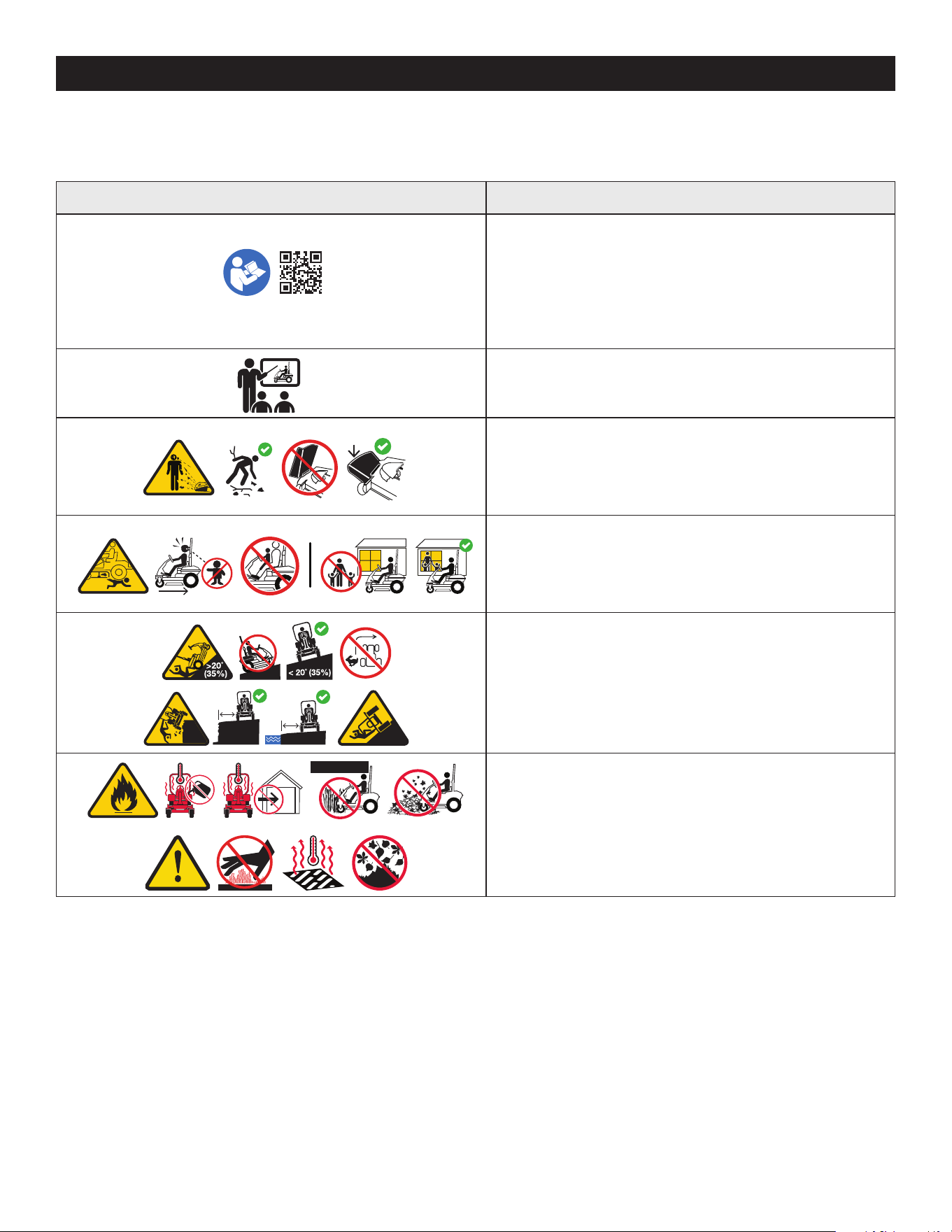
WARNING - READ OPERATOR’S MANUAL - Read, understand, and follow all the
safety rules and instructions in the manual(s) and on the mower before attempting
to operate this mower. Failure to comply with this information may result in
personal injury or death. Keep this manual in a safe location for future and regular
reference. Using a Smart Phone, scan the QR code symbol to learn more information
concerning the warnings contained on this mower. You can also go to www.
OPESymbol.com for more information.
WARNING - TRAINING - Read the Operator’s Manual and other training material. It
is the owner’s responsibility to provide training to operate or service the equipment.
WARNING - AVOID THROWN OBJECTS INJURY - Keep helpers at least 75 feet
(23 meters) from machine during operation. Remove all stones, sticks, wire,
bones, toys, and other foreign objects which could be picked up and thrown by
the blade(s). Do not operate the mower without the discharge cover or entire grass
catcher in its proper place.
WARNING - AVOID CHILD BACKOVER/RUNOVER/BLADE INJURY - To avoid
back-over accidents, always look behind and down for small children. Never carry
children, even with the blade(s) shut off. Keep bystanders, children, and pets inside
during operation under the watchful care of a responsible adult other than the
operator. Stop mower if anyone enters the area.
>10ft (3m)>10ft (3m)
>10ft (3m)>10ft (3m)
WARNING - AVOID TIP-OVER/ROLL-OVER INJURY - Do not operate machine on
a slope greater than 20° (35%). Do not mow up or down slopes, only mow across
slopes that are less than 20° (35%). Use low speeds and avoid sudden turns on
slopes. Stay at least 10 feet (3 meters) from drop-offs, ditches, embankments, or
the edge of water.
>10in (25c
m)
>10in (25
cm)
WARNING - AVOID FIRES - Your mower is designed to cut normal residential grass
of a height no more than 10” (25 cm). Do not attempt to mow through unusually
tall, dry grass (e.g., pasture), or piles of dry leaves. Allow mower to cool at least five
minutes before fueling or storing inside an enclosed garage or storage shed.
8
SAFE OPERATION PRACTICES
Symbol Description
1
2
3
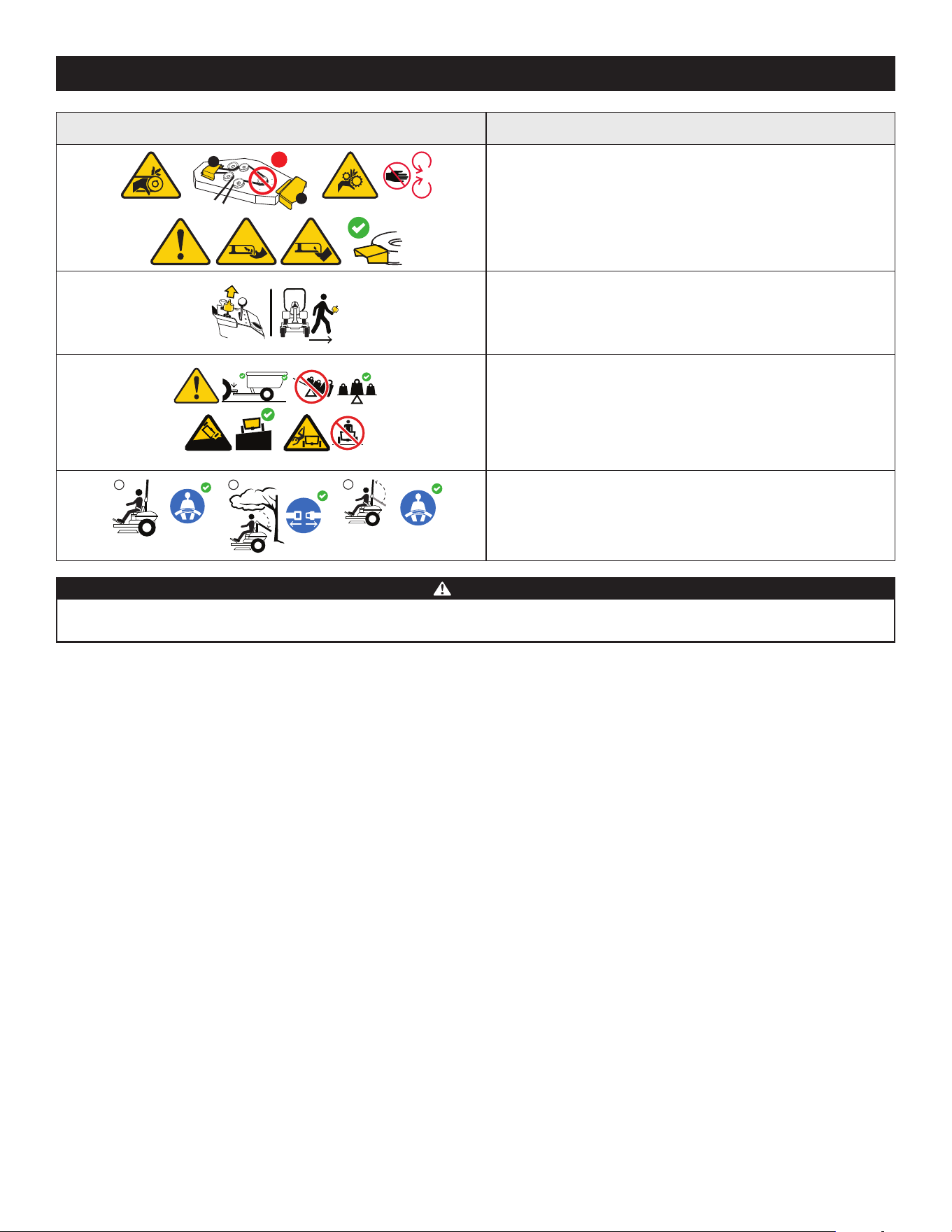
WARNING - AVOID AMPUTATION INJURY - Do not put hands or feet near rotating
parts or under the cutting deck. Contact with the blade(s) can amputate hands and
feet. Ensure that all safety devices (guards, shields, switches, etc.) are in place and
working. Belt and/or blade spindle contact can crush or injure body parts.
WARNING - REMOVE KEY - Always turn off blade(s), place the speed control pedals
in neutral, stop engine, and remove key before dismounting. If you are leaving the
mower unattended, always remove the key to prevent unauthorized use by children
or others.
>5˚(9%)
<5˚(9%)
<50lb
<500lb(226kg)
(22kg)
WARNING - AVOID TOWING RELATED INJURY - Do not tow a load that exceeds
500 lbs (226 kg) rolling weight and never exceed 50 lbs (22 kg) tongue weight.
Never allow children or others in or on towed equipment. Do not tow on slopes
greater than 5° (9%). On slopes, the weight of the towed equipment may cause loss
of traction, loss of control, and/or loss of the ability to stop. Travel slowly and allow
extra distance to stop.
1
2
3
WARNING - AVOID SERIOUS INJURY OR DEATH FROM ROLL OVER - Keep roll bar
in the raised upright position with your seat belt fastened. Lower roll bar and do
not fasten seat belt In low clearance situations. Raise roll bar and fasten seat belt as
soon as clearance permits.
WARNING
Your Responsibility—Restrict the use of this power machine to persons who read, understand, and follow the warnings and instructions in this manual and on
the machine - SAVE THESE INSTRUCTIONS!
9
SET-UPSET-UP
CONTENTS OF CARTON
• Zero-Turn Mower (1)
• Steering Wheel (1)
• Seat Tilt Knob Assembly & Hardware Pack (1)
• Seat Mounting Hardware (1)
• Battery Installation Hardware (1)
• Mower Operator’s Manual (1)
• Engine Operator’s Manual (1)
NOTE: This Operator’s Manual covers several models. Mower features may vary by
model. Not all features in this manual are applicable to all mower models and the
mower depicted may differ from yours.
NOTE: All references in this manual to the left or right side and front or back of the
machine are from the operating position only. Exceptions, if any, will be specified.
MOWER PREPARATION
TOOLS NEEDED: Safety glasses, leather gloves, wire cutters
1. Remove the upper crating material from the shipping pallet, and cut any bands
or tie straps securing the mower to the pallet.
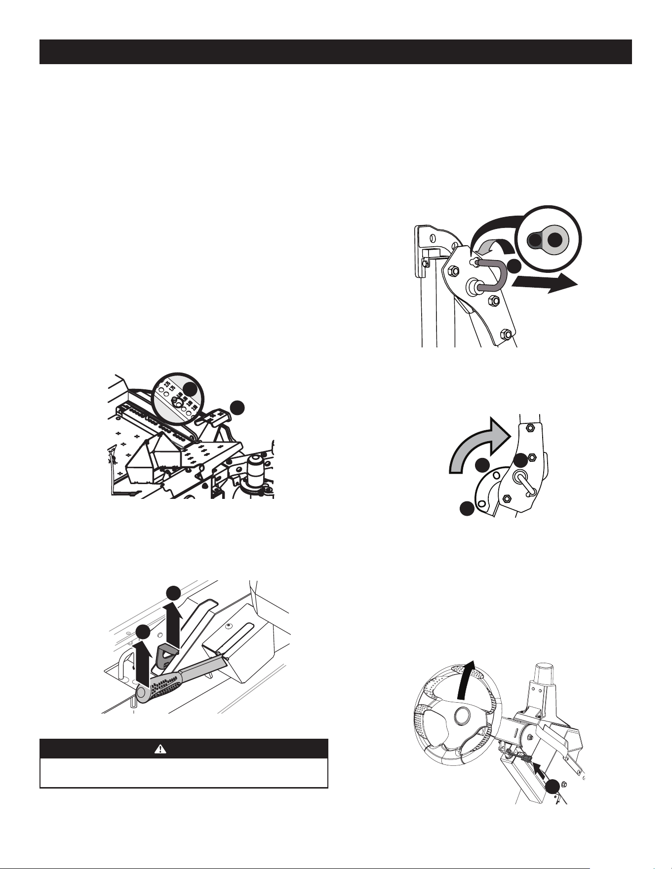
2. Use the deck lift pedal (a) to raise the deck to its highest position and secure in
place with the clevis pin (b) attached to the mower. See Figure 1.
a
b
Figure 1
3. The two hydrostatic transmissions are equipped with a bypass valve that will
allow you to manually move the mower short distances.
4. Engage the transmission bypass valves by pulling the bypass lever (a) outward
then upward and all the way back. See Figure 2.
a
b
Figure 2
WARNING
Do not tow the mower, even with the bypass valves engaged. Serious
transmission damage will result from doing so.
5. Carefully roll the mower off the shipping pallet.
6. To release the bypass lever (a), push the lever forward. See Figure 2.
7. To engage the parking brake, pull back completely on the parking brake lever
(b). See Figure 2.
8. Cut any wire ties holding the chute deflector up and discard any
packing material.
Roll Over Protective System (ROPS)
1. Pull slightly up on the upper ROPS to relieve any tension on the locking
pin (a) and rotate the locking pin (a) from the LOCKED (b)position into the
ADJUSTMENT (c) position. See Figure 3. Repeat the procedure for the locking
pin on the opposite side.
a
b
c
Figure 3
2. When both locking pins are secured in the ADJUSTMENT position, slowly lift and
rotate the upper ROPS from the TRANSPORT (a) position, past the TRANSPORT
WITH BAGGER (b) position and into the OPERATION (c) position. See Figure 4.
a
b
c
Figure 4
3. Rotate both locking pins into the LOCKED position. Move the upper ROPS
slightly until the locking pins are fully engaged in the LOCKED position.
Steering Wheel Column
The steering wheel column is tilted all the way down for shipping purposes. To
adjust the column pull up on the steering column adjustment lever (a) and move
the steering column up into the desired position. Release the steering column
adjustment lever (a) to secure the steering column in the desired position. See
Figure 5.
a
Figure 5
10
SET-UP
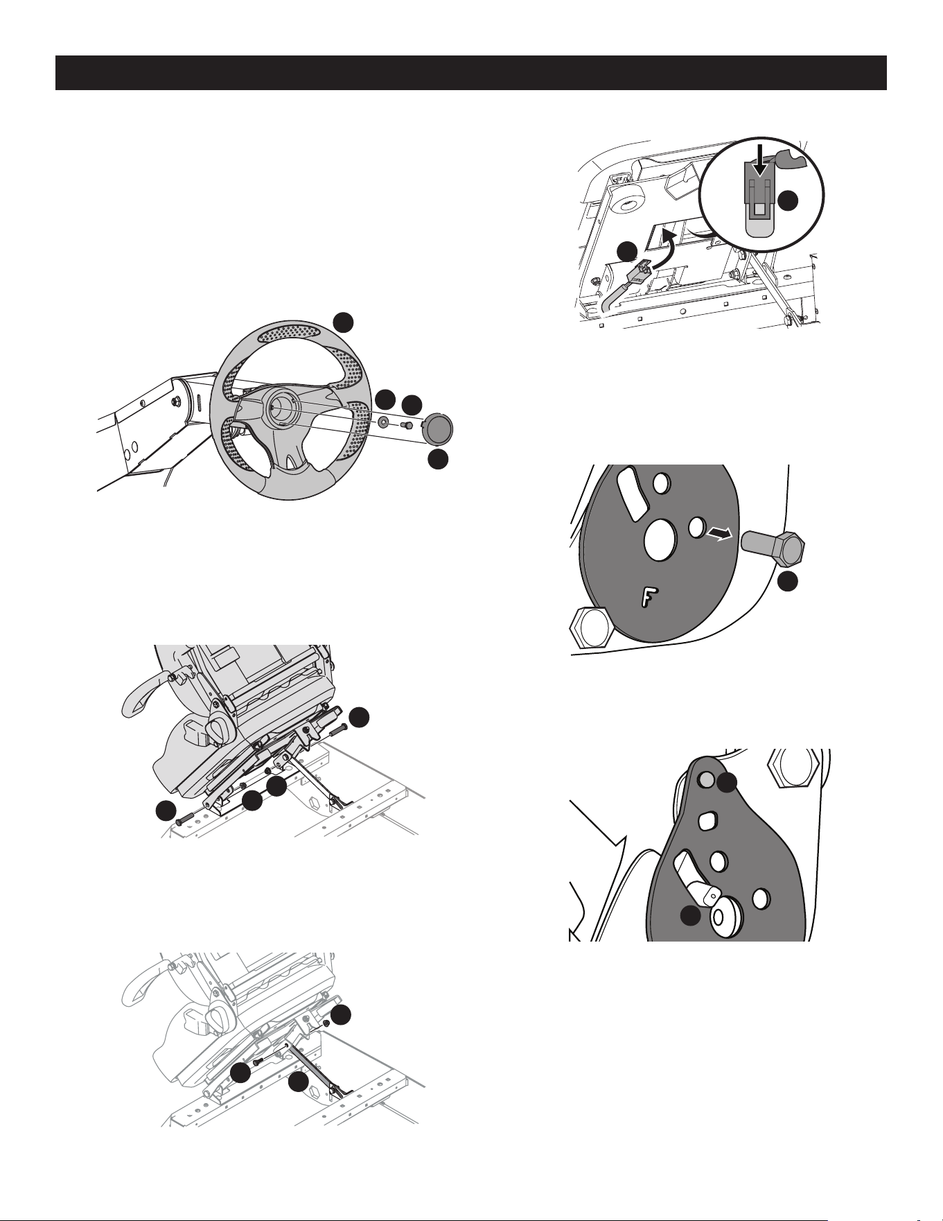
4. Insert the wiring harness (a) into the bottom of the seat as shown in Figure 9.
a
a
Figure 9
NOTE: When the wiring harness (a) is connected, be sure to push the excess
wire from the wire harness (a) into the seat box hole before continuing. See
Figure 9.
5. Remove the screw (a) securing the recliner plate in the seat back position. See
Figure 10.
a
Figure 10
6. Tilt the seat forward into the full forward position. Replace the recliner plate
with the clinch-stud (a) and the recliner pin (b) passing through the recliner
plate in the locations shown in Figure 11.
a
b
Figure 11
Steering Wheel
IMPORTANT! Do not use impact tools to install or remove the steering wheel. Doing
so may cause damage to critical power steering components.
1. Remove the hardware for attaching the steering wheel from beneath the
steering wheel cap (a). Carefully pry off the steering wheel cap (a) to remove
the hardware. See Figure 6.
2. With the wheels of the machine pointing straight forward, place the steering
wheel (b) over the steering shaft. See Figure 6.
3. Place the Belleville washer (c) over the steering wheel (b) and secure with the
hex lock screw (d). See Figure 6.
a
b
c
d
Figure 6
4. Place the steering wheel cover over the center of the steering wheel and push
downward until it “clicks” into place.
OPERATOR’S SEAT
1. Remove the two flange lock nuts (b) and shoulder bolts (a) from the manual
bag. See Figure 7.
a
a
b
b
Figure 7
2. Place the seat into position and secure the seat into place with the hardware as
shown in Figure 7.
3. Remove the shoulder screw (a) and flange lock nut (b) from manual bag and
install the seat lockout bracket (c) as shown in Figure 8.
a
b
c
Figure 8
11
SET-UP
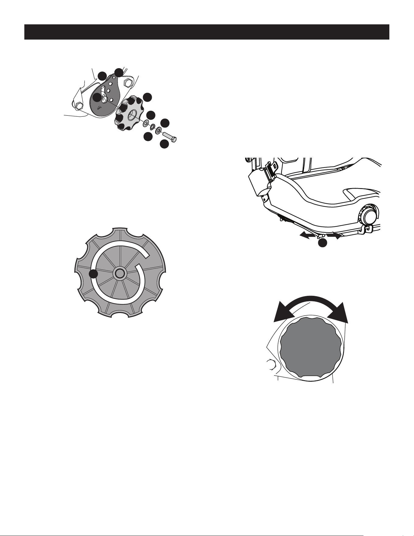
7. Remove the seat tilt knob assembly from the bag and install as shown in
Figure 12.
a
b
c
d
e
f
h
g
Figure 12
NOTE: Be sure to orient the recliner plate (a) and install the plastic washer
(b), spring washer (c) and metal washer (d) as shown in Figure 12. The plastic
washer is on the inside.
8. Slide the recliner bearing plate (a) onto the recliner pin (e). Refer to Figure 12.
9. Then align the spiral (a) on the inside of the recliner knob with the recliner pin.
Make sure the hub on the back of the recliner sits properly into the large holes
of the side plate. See Figure 13.
a
Figure 13
10. Use a wrench to hand tighten the hex screw (g) until the recliner knob (f) is
difficult to turn. Refer to Figure 12.
NOTE: Do not use power tools to install.
11. Gradually loosen the hex screw (g) until the recliner knob moves freely. Do not
loosen the hex screw (g) more than one full turn. Refer to Figure 12.
12. Securely install the 1/4” nut onto the clinch-stud (h) and rotate the recliner
knob to check the operation of the seat. Refer to Figure 12.
SEAT ADJUSTMENT
Proper steering column and seat adjustment will result in the following (to adjust the
seat see below):
In the neutral position with hands on the steering wheel,
• Operator’s upper arms should be relaxed and approximately vertical.
• Operator’s forearms should be approximately horizontal.
• Operator’s back should stay in contact with the seat back.
• Steering column should not contact operator’s legs.
Check the results of any adjustments to the conditions described above. Repeat any
adjustment procedures as required until all conditions are met.
This machine is equipped with an adjustable seat, which includes a retractable seat
belt assembly and an Operator Presence Sensor (OPS). The OPS, in the form of a
switch, is integrated into the seat bottom and is connected to the machine electrical
system. The OPS must be connected to the electrical wiring harness.
The seat can be adjusted forward and backward, the armrests can be adjusted up
and down, and air ride adjustment, a lumbar support, can be adjusted. The seat can
also tilt forward and backward.
NOTE: The seat base must be secured by the latch, otherwise, the seat assembly
could tilt forward.
Seat Position
To move the seat forward or back, locate the seat adjustment rod (a) under the seat.
Push the rod to the left, slide the seat forward or back into the desired position and
release the rod when the seat is in the desired position. See Figure 14.
a
Figure 14
Seat Tilt
The seat tilt is controlled by the knob on the left of the seat. Turn the knob rearward
to tilt the seat back, turn the knob forward to tilt the seat forward. See Figure 15.
Figure 15
12
SET-UP
Seat Lumbar
To vary the lumbar support move the lever on the right of the seat up and down. See
Figure 16.
Figure 16
Seat Arm Rest
To adjust the height of the arm rests, lift the arm rest and rotate the knob under the
arm rest right or left to increase or decrease the height. See Figure 17.
Figure 17
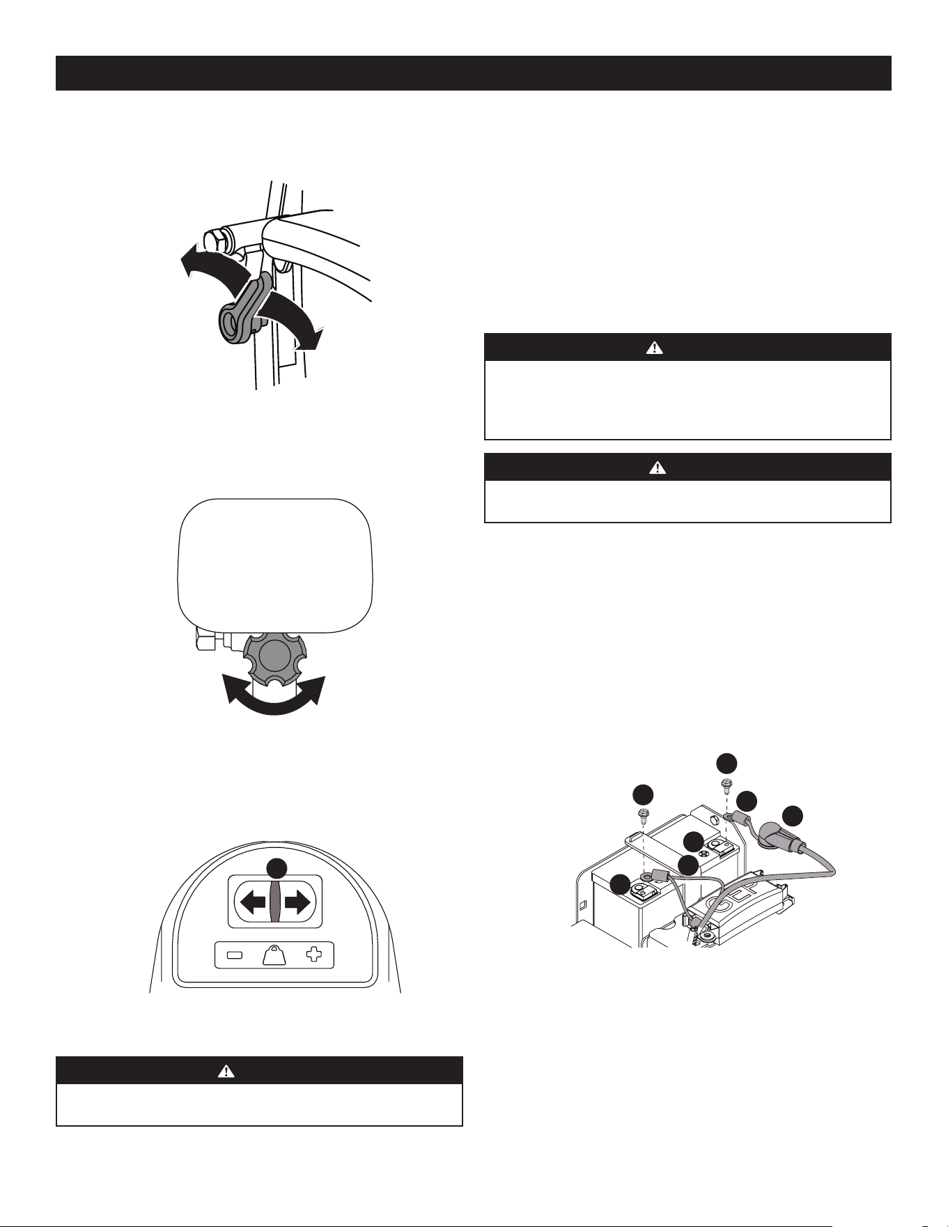
Seat Air Ride
The air ride can be adjusted up or down using the height adjustment lever (a) on the
front of the seat. Press the lever to the left (+) to raise the height of the seat and to
the right (-) to lower the height of the seat. See Figure 18.
a
Figure 18
CHECKING TIRE PRESSURE
WARNING
Maximum tire pressure under any circumstances is 12 psi on rear tires and 25
psi on front tires. Equal tire pressure should be maintained at all times.
INFLATION PRESSURE
Rear Tires — 10-12 psi max
Front Tires — 20-25 psi max
The tires on your mower may be over-inflated for shipping purposes. Reduce the tire
pressure before operating the mower. Recommended operating tire pressure is 10-12
psi on rear tires and 20-25 psi on front tires.
LUBRICATION & GREASE POINTS
Before operating the mower, refer to the Product Care section of this manual to check
the lubrication and grease points. Grease and lubricate if necessary.
CONNECTING THE BATTERY CABLES
WARNING
CALIFORNIA PROPOSITION 65: Battery posts, terminals, and related
accessories contain lead and lead compounds, chemicals known to the State
of California to cause cancer and reproductive harm. Wash hands after
handling.
CAUTION
When attaching battery cables, always connect the POSITIVE (Red) wire to
its terminal first, followed by the NEGATIVE (Black) wire.
For shipping reasons, both battery cables on your equipment may have been left
disconnected from the terminals at the factory. To connect the battery cables,
proceed as follows:
1. Using the lever on either side of the back of the seat, lift up on the lever and tilt
the seat forward locking it in place with the seat prop. Remove the bolts and
hex nuts from the manual bag.
NOTE: The positive battery terminal is marked POS. (+) (a). The negative
battery terminal is marked NEG. (–) (b). See Figure 19.
NOTE: If the positive battery cable (c) is already attached, skip ahead to Step 4.
2. Slide the red boot (d) from the positive battery terminal (a) and attach the red
cable (c), with the vertical mount bolt (e). See Figure 19.
a
b
c
d
e
e
f
Figure 19
3. Position the red boot (d) over the positive battery terminal (a) to insulate it and
help protect it from corrosion.
4. Attach the black cable (f), to the negative battery terminal (b) with the vertical
mount bolt (e). See Figure 19.
NOTE: If the battery is put into service after the date shown on top/side of
battery, charge the battery prior to operating the machine.
CONNECTING TO THE GPS NETWORK
See the Operation section for instructions on connecting to the GPS Network.
13
OPERATIONOPERATION
NOTE: This Operator’s Manual covers several models. Mower features may vary by
model. Not all features in this manual are applicable to all mower models and the
mower depicted may differ from yours.
NOTE: All references in this manual to the left or right side and front or back of the
machine are from the operating position only. Exceptions, if any, will be specified.
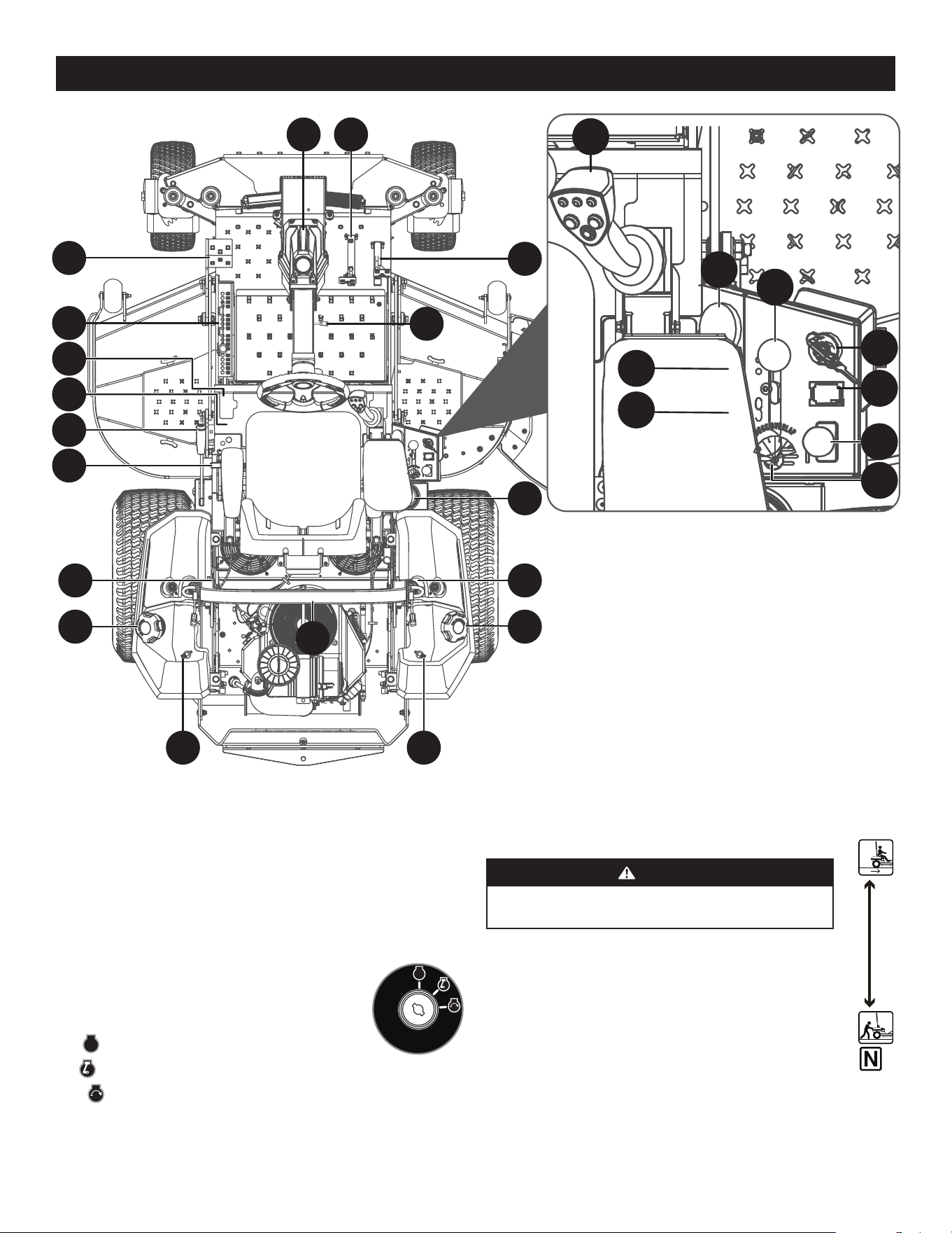
A. IGNITION
The ignition switch is located on the RH console to the rear of
the throttle control. The ignition switch has three positions
as follows:
STOP
STOP
— The engine and electrical system are turned off.
RUN — The mower electrical system is energized.
START — The starter motor will turn over the engine. Release the key
immediately when the engine starts.
NOTE: To prevent accidental starting and/or battery discharge, remove the key from
the ignition switch when the mower is not in use.
STOP
AD I
J
W
X
AB
†
K
AC
B
AB
†
K
AC
Y
H
S
G
†
U
†
T
†
Z
AA
†
D
C
F
A
E
†
AB
†
AE
Figure 20
B. TRANSMISSION BYPASS LEVER
WARNING
Do not tow the mower, even with the bypass valves engaged.
Serious transmission damage will result from doing so.
The transmission bypass lever is located next to the LH console to the left
of the operator’s seat.
When engaged the valves open a bypass within the hydrostatic
transmissions. Refer to the Set-Up section for instructions on using the
bypass feature.
14
OPERATION
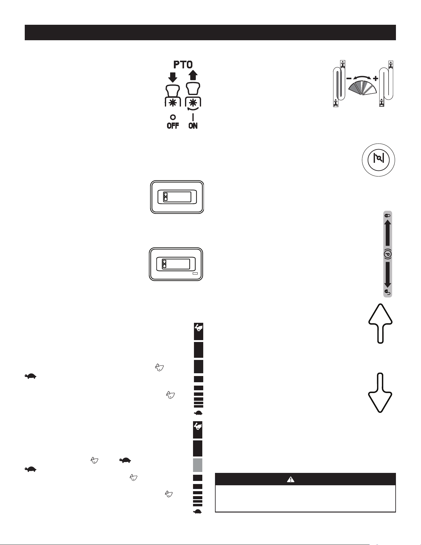
C. POWER TAKE-OFF (PTO) KNOB
The PTO knob is located on the RH console to the right of the
operator’s seat.
The PTO knob operates the electric PTO clutch mounted on
the bottom of the engine crankshaft. Pull the knob upward
to engage the PTO clutch, or push the knob downward to
disengage the clutch.
The PTO knob must be in the OFF position when starting
the engine.
D. HOUR METER & SERVICE MINDER
The hour meter and service minder is located on the RH console to the right of the
operator’s seat. It records the hours that the mower has been operated and engine
speed (RPM) in the digital display.
Hour Meter (if equipped)
The hour meter is activated whenever the ignition
switch is turned to the ON position. Keep a record
of the actual hours of operation to assure all
maintenance procedures are completed according to the
instructions in this Operator’s Manual and the Engine
Operator’s Manual.
Hour Meter & Service Minder with MODE Button (if equipped)
The hour meter and service minder is activated
whenever the ignition switch is turned to the ON
position. Keep a record of the actual hours of operation
to assure all maintenance procedures are completed
according to the instructions in this Operator’s Manual
and the Engine Operator’s Manual. The hour meter and service minder is equipped
with a MODE button that can toggle between available functions and can be used to
reset service alerts. Press and hold the MODE button for 3 seconds while in service
alert mode or when in a service alarm mode to reset.
E. THROTTLE
Manual Throttle (If equipped)
The throttle control is located on the RH console to the right of the
operator’s seat. When set in a given position, a uniform engine speed will
be maintained. The throttle control moves between the FAST and slow
positions.
Push the throttle control handle forward to increase the engine speed. The
mower is designed to operate with the throttle control in the FAST (full
throttle) position when the mower is being driven and the mower deck
is engaged.
Pull the throttle control handle rearward to decrease the engine speed.
Electronic Throttle (E-Governor) Lever (If equipped)
The electronic throttle (E-governor) lever is used to control engine speed
and RPM’s. It also helps control fuel efficiency. The electronic throttle
lever moves between the FAST and slow positions. The SLOW
position is used for basic transportation of the mower with the
PTO disengaged and uses the least fuel. The FAST position should be
used when the PTO is engaged and uses the most fuel. The mower should
be started in the START position, but should always be in the FAST
position when the PTO/deck is being used.
0.0
0.0
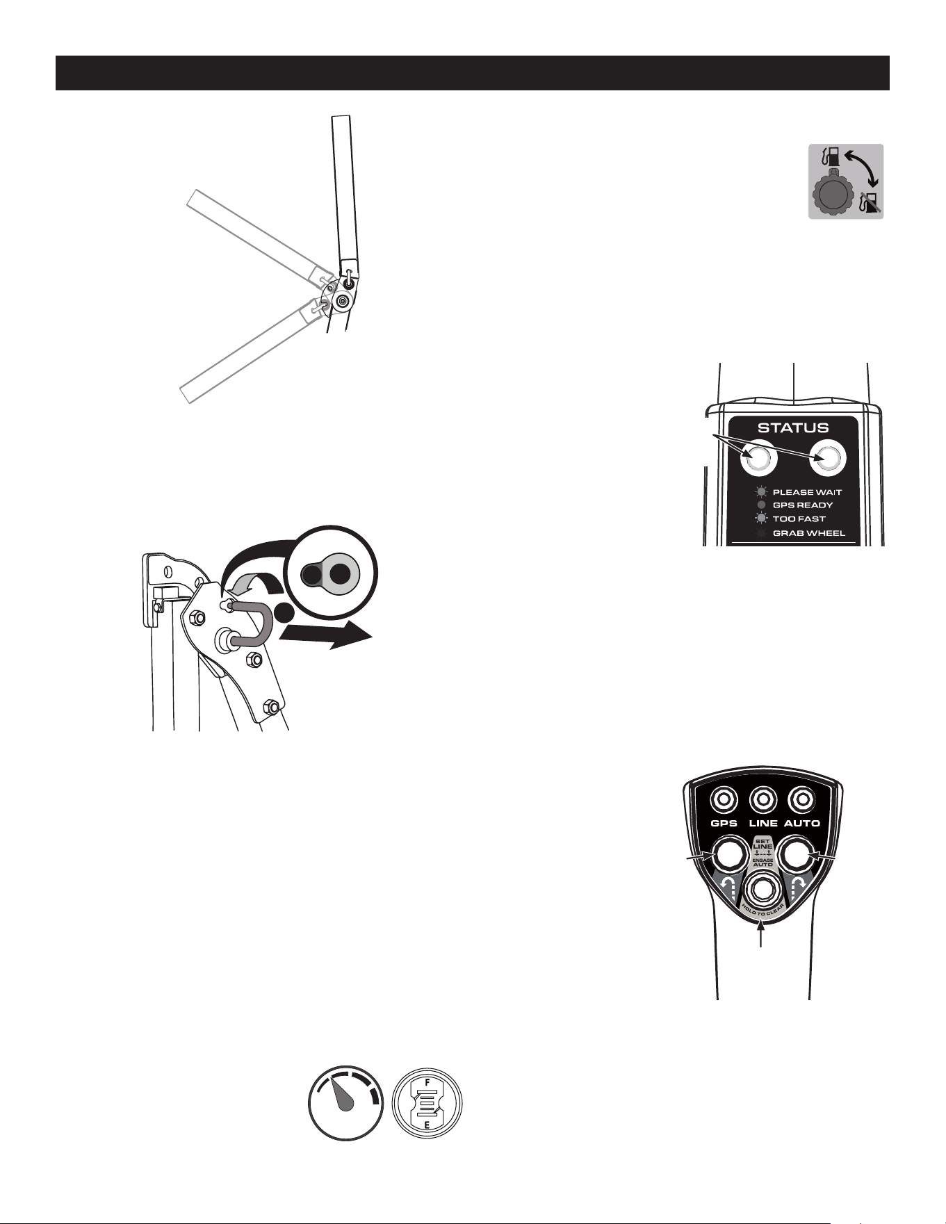
F. CUTTING WIDTH KNOB
The cutting width knob, only available when mower
is in SurePath Auto Steer Mode, is located on the RH
console to the right of the operator’s seat and has four
positions. MOST EFFICIENT is suitable for most terrains
and maintains standard mowing path overlap. Turn
dial progressively from right to left if operating under
extreme conditions or if visible sections of uncut
grass occur when mower is in MOST EFFICIENT setting.
G. CHOKE KNOB (IF EQUIPPED)/MIL (IF EQUIPPED)
Choke Knob (if equipped) - The choke knob is located on the
left side of the mower next to the operator’s seat. Pull the knob
out to choke the engine; push the knob in/down to open the choke.
Having the choke in the ON position helps the engine to start
during initial start-up. During normal operation the choke should
be OFF.
MIL (if equipped) - The Multifunction Indicator Light (MIL) provides diagnostic
information for the engine. If the MIL lights up and/or flashes see the service manual
or contact your service center.
H. PARKING BRAKE LEVER
The parking brake lever is located to the left of the operator’s seat. When
pulled up it engages the parking brake and when pushed down it releases
the brake.
NOTE: If the forward or reverse drive pedal is engaged when engaging the
parking brake, the engine will stop. The parking brake must be placed in the
engaged position when starting the engine.
I. FORWARD DRIVE PEDAL
The forward drive pedal is located on the right side of the machine,
directly to the right of the steering column and along the running
board. Press the forward drive pedal forward to cause the mower
to travel forward. Ground speed is also controlled with the forward
drive pedal. The further forward the pedal is pivoted, the faster
the mower will travel. The pedal will return to its original/neutral
position when it is not pressed.
J. REVERSE DRIVE PEDAL
The reverse drive pedal is located on the right side of the mower,
to the right of the forward drive pedal, along the running board.
Ground speed is also controlled with the reverse drive pedal. The
further downward the pedal is pivoted, the faster the mower will
travel. The pedal will return to its original/neutral position when it
is not pressed.
K. FUEL TANK CAPS
The fuel tank caps are located on the top of the fuel tank on the left and right side
of the seat. Turn the fill cap counter-clockwise to remove and clockwise until it
clicks three times to tighten. Always re-install the fuel cap tightly onto the fuel tank
after removing.
WARNING
Never fill the fuel tank when the engine is running. If the engine is hot from
recently running, allow to cool for several minutes before refueling. Highly
flammable gasoline could splash onto the engine and cause a fire.

15
OPERATION
U. TRANSPORT LOCK (IF EQUIPPED)
The transport lock is located on the left side of the
operator’s seat and is used to lock the deck in the
transport position. Press down on the deck lift pedal,
lift the transport lock rod up off the pressure plate and
rotate counter-clockwise until the free end drops into the
open hole to lock the deck. To release the deck, reverse
the process.
V. TRANSMISSION OIL EXPANSION RESERVOIR (NOT SHOWN,
IF EQUIPPED)
The 900 series is equipped with a transmission oil expansion reservoir located under
the seat, connected by hoses to the RH and LH transmission assemblies. The function
of the reservoir is to hold the natural expansion of transmission oil that occurs as the
transmission warms up during operation. DO NOT FILL THE RESERVOIR.
Under normal operating conditions, no oil should be added to the reservoir. The
COLD oil level should be approximately 1/4” above the bottom of the reservoir on
900 models. See the Product Care section of this manual for more information on the
transmission oil expansion reservoirs.
NOTE: Prior to the initial operation of the mower, the oil level in the reservoir may
be slightly higher than the maximum due to air in the oil lines. Operation of the
mower will eventually purge the air from the lines and the oil level will settle to
the maximum.
W. STEERING COLUMN ADJUSTMENT LEVER
The steering column adjustment lever is located on the right side of the steering
column. To adjust the column pull up on the steering column adjustment lever and
move the steering column up into the desired position. Release the steering column
adjustment lever to secure the steering column in the desired position.
X. CUP HOLDER
The cup holder is located between the fuel tank and the control panel to the right of
the seat.
Y. ROLL OVER PROTECTIVE STRUCTURE (ROPS)
ROPS Position
Refer to Figure 21 on page 16 and the following descriptions and uses for the three
(3) positions for the ROPS.
• TRANSPORT: Only to be used when transporting the mower or when they
need to be momentarily folded-down to avoid contact with items such as tree
limbs, clothes lines, guy wires, utility poles, buildings, etc.
• TRANSPORT WITH BAGGER: Allows for the ROPS to be lowered for situations
outlined for the TRANSPORT position when the mower is equipped with
a bagger.
• OPERATION: The ROPS should always be in this position when operating
unless the situations involved outlined in the TRANSPORT and TRANSPORT
WITH BAGGER descriptions arise.
L. SEAT ADJUSTMENT LEVER (NOT SHOWN)
The seat adjustment lever is located below the front/right of the seat. The lever
allows for adjustment forward or rearward of the operator’s seat. Refer to the Set-Up
section for instructions on adjusting the seat position.
M. SEAT TILT KNOB (NOT SHOWN)
The seat tilt knob is located on the left side of the seat. Refer to the Set-Up section for
instructions on adjusting the seat tilt.
N. ARM REST HEIGHT KNOBS (NOT SHOWN, IF EQUIPPED)
The arm height knobs are located under the seat arms and can be used to adjust the
height of the arm rests. Refer to the Set-Up section for instructions on adjusting the
arm rest position.
O. MECHANICAL SUSPENSION MECHANISM (NOT SHOWN,
IF EQUIPPED)
The mechanical suspension mechanism is located on the front of the seat and can
adjust the weight/ride adjustment for operators in the 125- to 275-pound weight
range. Refer to the Set-Up section for instructions on adjusting the mechanical
suspension mechanism.
P. LUMBAR SUPPORT LEVER (NOT SHOWN, IF EQUIPPED)
The lumbar support lever is located on the right side of the seat on the seat back.
Refer to the Set-Up section for instructions on adjusting the lumbar support.
Q. SEAT PROP (NOT SHOWN)
The seat prop is located on the left, rear side of the operator’s seat. It is used to prop
the seat forward.
R. SEAT LATCH (NOT SHOWN)
The seat latch is located below the rear, center of the operator’s seat. The latch is used
to secure the seat into the operating position. Lift the latch and tilt the seat forward
to access the area under the seat.
S. DECK HEIGHT INDEX
The deck height index consists of several holes located on the left of the foot
platform. Each hole corresponds to a 1/4” change in the deck height position ranging
from 1” at the lowest notch to 5” at the highest notch.
T. DECK LIFT
Deck Lift Pedal (if equipped)
The deck lift pedal is located on the left front corner of the foot platform, and is used
to raise and lower the mowing deck.
To raise the mowing deck to the transport position, push the pedal all the way
forward until the deck transportation lock snaps into position. To remove the deck
from the transport position push forward on the deck lift pedal and pull up on the
deck lock rod. To position the deck push the pedal all the way forward, remove the
clevis pin, reinsert it in the desired cutting height and slowly release pressure on the
pedal until you reach the clevis pin.
4.50
"
3.
5
0"
2.50"
1.
5
0"
4.75"
3.75"
2.75
"
1.75"
5
"
4
"
3"
2"
1"
3.25"
4.
25
"
2.25
"
1.2
5
"
16
OPERATION
Transport Position
Transport with
Bagger Position
Operation Position
Figure 21
1. To change the position of the ROPS, pull slightly up/push forward on the upper
ROPS to relieve any tension on the locking pin (a) and rotate the locking pin
(a) from the LOCKED (b) position into the ADJUSTMENT (c) position. Repeat the
procedure for the locking pin on the opposite side. See Figure 22.
a
b
c
Figure 22
2. Move the ROPS into the desired position. The three positions are TRANSPORT
position, TRANSPORT WITH BAGGER position and into the OPERATION position.
See Figure 21.
3. Rotate both locking pins into the LOCKED position. Move the upper ROPS
slightly until the locking pins are fully engaged in the LOCKED position.
Z. ACCESSORY SWITCH RECEPTACLES
The two receptacles for optional accessories are on the RH console. See the
Replacement Parts and Accessories section for information.
AA. 12V OUTLET (IF EQUIPPED)
The 12V outlet is located to the right of the operator’s seat on the lower panel of the
RH console and is used for the convenience of plugging in accessories that require a
power source with a maximum load of 5A at 12V.
AB. FUEL GAUGE(S)
There is a fuel gauge on top of each of the two
fuel tanks or a single gauge to the right of the
operator’s seat on the RH console. The gauges
measure the fuel level in each tank.
AC. FUEL VALVES
The fuel valves are located near the rear of each fuel tank.
The valve controls the fuel flow from the right and left tank
and also can shut off fuel flow to the engine. Rotate the valve
counter-clockwise to open the flow from the tank(s). Rotate the
valve clockwise to stop the flow from the tank(s). The fuel tanks
can be operated together, independently or shut the fuel flow
off completely.
NOTE: If both tanks are on, and one is empty, the engine will not start. Be certain to
make sure both tanks have fuel or that the empty tank’s fuel valve is closed.
AD. GLOBAL POSITIONING MODULE (GPM) (SUREPATH AUTO
STEER SYSTEM)
The Global Positioning Module
(GPM), mounted to the front of the
steering wheel column, is the main
component of the SurePath Auto
Steer system.
The GPM includes:
• Light Module (Indicator/
Warning Lights) - the
Indicator/Warning Lights are
mounted on the back (facing
the operator) of the GPM and visually communicate the status of the SurePath
Auto Steer system to the operator. The two lights will always match in color
and operation (flashing or solid).
• 4G Modem Antenna - integrated antenna for the 4G Modem.
• On-Board Computer - the GPM houses the main microprocessors, software and
logic to provide guidance to the equipment’s drive systems.
See Service in the Product Care section for information on servicing the GPM.
AE. OPERATOR CONTROL PANEL (SUREPATH AUTO
STEER SYSTEM)
GPS — Green indicators will
flash on the Light Module and
Operator Control Panel GPS
indicator while the GPM is
actively searching for a signal
and will turn solid green when
signal is acquired.
LINE — Initially the LINE
indicator will be off. The LINE
indicator will flash green when
first point (A) has been set
and will turn solid green once
second point (B) has been set.
IMPORTANT! Operator should drive a minimum of 10 yards (30 feet) between
setting point A and point B.
AUTO — The AUTO indicator will be solid green when mower is in auto mode and
will flash slowly when mower is in manual mode with auto mode available (points
A and B have been set and GPS signal is good). The AUTO indicator is off when the
mower is not ready for auto mode.
Blue
Blue
Z
Blue
Green
Yellow
Red
Indicator/
Warning
Lights
SET LINE/
ENGAGE AUTO
Button
Left Turn
Button
Right Turn
Button

17
OPERATION
NOTE: Auto indicator will only flash after overriding auto mode by turning the
steering wheel slightly to the right or left or if the system loses GPS signal. Points A
and B remain set.
LEFT TURN BUTTON — Mower will perform an automated zero turn to the left while
in SurePath Auto Steer Mode.
RIGHT TURN BUTTON — Mower will perform an automated zero turn to the right
while in SurePath Auto Steer Mode.
SET LINE/ENGAGE AUTO BUTTON — Sets beginning (A) and ending (B) points for
automatic mowing. This button is also used to resume auto mode (press once after
system is disengaged).
NOTE: SET LINE/ENGAGE AUTO button also serves as the reset button to clear the set
line. See Clearing the Mowing Line (SurePath Auto Steer Mode) later in this section
for more information.
BEFORE OPERATING YOUR MOWER
1. Before you operate the mower, study this manual carefully to familiarize
yourself with the operation of all the instruments and controls. It has been
prepared to help you operate and maintain your machine efficiently.
2. Fill the fuel tank with only clean, fresh, unleaded gasoline with a pump sticker
octane rating of 87 or higher. When the fuel reaches 1/2” below the bottom of
the fill neck, stop. DO NOT OVERFILL. Space must be left for expansion.
3. Never use gasoline containing more than 10% ethanol or methanol.
4. Check the engine oil level as instructed in the Engine Operator’s Manual.
5. Check the transmission oil level. The transmission oil expansion reservoir
is located beneath the operator’s seat. Always wipe off the area around
the reservoir fill neck before checking the oil level to prevent dirt from
contaminating the oil. Remove the cap and make sure the oil level is 1/4”
above the bottom of the reservoir. If the oil level is low, fill with Castrol™
(Syntec®) Edge™.
6. Check the tire inflation pressures. 10-12 psi for the rear tires, 20-25 psi for the
front tires.
NOTE: New tires are over-inflated in order to properly seat the bead to the rim.
7. Check that all nuts, bolts and screws are tight.
8. Check the tension of the deck drive belts.
a. Remove the deck cover.
b. The tension of the deck drive belts are maintained by a spring mechanism
that adjusts for wear and stretch.
c. Examine the belts for cuts, fraying and excessive wear. Replace if any of
these are detected.
d. Replace the deck cover.
9. Check if deck is level. When correctly adjusted the mower deck should be level
side to side, and the front of the deck should be approximately 1/4” lower than
the rear of deck. If deck needs to be leveled, refer to the Product Care section.
10. Lubricate all pivot points listed in the Product Care section.
11. Adjust the seat for operator’s maximum comfort, visibility and for maintaining
complete control of the machine. Refer to the Set-Up section for instructions on
adjusting the seat.
SAFETY INTERLOCK SYSTEM
This machine is equipped with a safety interlock system for the protection of the
operator. If the interlock system should ever malfunction, do not operate the
machine. Contact your authorized service dealer.
• The safety interlock system prevents the engine from cranking or starting
unless the speed control pedals are in the neutral position, the parking brake is
engaged and the PTO knob is disengaged.
• To avoid sudden movement when disengaging the parking brake, the safety
interlock system will shut off the engine if the speed control pedals are
moved to a position other than the neutral position when the parking brake
is engaged.
• The safety interlock system will shut off the engine if the operator leaves the
seat before engaging the parking brake.
• The safety interlock system will shut off the engine if the operator leaves the
seat with the PTO knob engaged, regardless of whether the parking brake
is engaged.
NOTE: The PTO knob must be in the disengaged position to restart the engine.
Practice Operation (Initial use)
Operating a zero-turn mower is not like operating a conventional type riding mower.
Although and because a zero-turn mower is more maneuverable, getting used to
operating the speed control pedals and the steering wheel takes some practice.
It is strongly recommended that you locate a reasonably large, level and open
“practice area” where there are no obstructions, pedestrians or animals. You should
practice operating the mower for a minimum of 30 minutes.
Carefully move (or have moved) the mower to the practice area. When performing
the practice session, the PTO knob should not be engaged. While practicing, operate
the mower at approximately 1/2-3/4 throttle and at less than full speed in both
forward and reverse.
Always wear appropriate clothing and personal protective equipment (e.g. safety
glasses, long pants, gloves, hearing protection, safety shoes, hard hat) when
operating or maintaining this machine. Follow all federal, state and local guidelines
regarding the use of personal protective equipment.
WARNING
Hearing protection is required for all operator exposure exceeding two
(2) hours.
Carefully practice maneuvering the machine using the instructions in the Driving
the Mower section. Practice until you are confident that you can safely operate
the mower.
STARTING THE ENGINE
For throttle/choke or throttle/automatic EFI engines proceed below, for electronic
throttle/EFI engines, skip ahead to the Electronic Throttle (E-Governor)/EFI
(Electronic Fuel Injection) Engines section.
Manual Throttle/Choke or Throttle/Automatic EFI (Electronic Fuel
Injection) Engines
WARNING
This machine is equipped with a safety interlock system designed for
protection of the operator. Do not operate the machine if any part of the
interlock system is malfunctioning. Periodically check the functions of the
interlock system for proper operation.

18
OPERATION
Cold Weather Starting
When starting the engine at temperatures near or below freezing, ensure the correct
viscosity motor oil is used in the engine and the battery is fully charged. Start the
engine as follows:
1. Be sure the battery is in good condition. A warm battery has much more
starting capacity than a cold battery.
2. Use fresh winter grade fuel. Winter grade gasoline has higher volatility to
improve starting. Do not use gasoline left over from summer.
3. Follow the previous instruction for Starting the Engine.
Using Jumper Cables to Start Engine
WARNING
Batteries contain sulfuric acid and produce explosive gases. Make certain
the area is well ventilated, wear gloves and eye protection, and avoid sparks
or flames near the battery.
If the battery charge is not sufficient to crank the engine, recharge the battery. If a
battery charger is unavailable and the mower must be started, the aid of a booster
battery will be necessary. Connect the booster battery as follows:
1. Connect the end of one cable to the disabled mower battery’s positive
terminal; then connect the other end of that cable to the booster battery’s
positive terminal.
2. Connect one end of the other cable to the booster battery’s negative terminal;
then connect the other end of that cable to the frame of the disabled mower, as
far from the battery as possible.
3. Start the disabled mower following the normal starting instructions previously
provided; then disconnect the jumper cables in the exact reverse order of
their connection.
4. Have the mower’s electrical system checked and repaired as soon as possible to
eliminate the need for jump starting.
Stopping the Engine
1. Place the PTO switch in the disengaged position.
2. Engage the parking brake.
3. Move the throttle to the SLOW position and allow the engine to idle for
about one minute.
4. Turn the ignition key to the OFF position and remove the key from the
ignition switch.
NOTE: Always remove the key from the ignition switch to prevent accidental
starting or battery discharge if the equipment is left unattended.
5. Close the fuel shut-off valve(s).
DRIVING THE MOWER
1. Ensure that the area is free of animals and bystanders, especially children.
2. Survey the area where the equipment is to be used to make sure it is free of
debris, sticks, stones, wires, bones and other foreign objects which could cause
injury to bystanders, damage to the machine or damage to nearby facilities.
WARNING
Avoid sudden starts, excessive speed, and sudden stops.
WARNING
For personal safety, the operator must be sitting in the mower seat when
starting the engine.
1. Open the fuel valve(s).
NOTE: If both tanks are on, and one is empty, the engine will not start. Be
certain to make sure both tanks have fuel or that the empty tank’s fuel valve
is closed.
2. Operator must be sitting in the mower seat with both drive control pedals in
the neutral/start position.
3. Engage the parking brake.
4. Make certain the PTO is in the disengaged (down) position.
5. Lift the choke knob (if equipped) into the ON position.
NOTE: If the engine is warmed up, it may not be necessary to choke the engine.
NOTE: Some mowers are equipped with EFI (Electronic Fuel Injection) engines
and are not equipped with a choke.
6. Move the throttle control to midway between the SLOW and FAST
positions.
7. Turn the ignition key clockwise to the START position and release it as soon as
the engine starts; however, do not crank the engine continuously for more than
10 seconds at a time. If the engine does not start within this time, turn the key
to OFF and wait at least 30 seconds to allow the engine’s starter motor to cool.
Try again after waiting. If after a few attempts the engine fails to start, do not
keep trying to start it with the choke closed as this will cause flooding and
make starting more difficult.
8. Once the engine starts, push the choke (if equipped) halfway down and as the
engine warms, push the choke (if equipped) all the way down.
Electronic Throttle (E-Governor)/EFI (Electronic Fuel
Injection) Engines
1. Open the fuel valve(s).
NOTE: To prime a dry fuel system, turn the ignition switch to the ON position
for one minute. Allow the fuel pump to cycle and prime the system. Turn the
ignition switch to the OFF position.
NOTE: If both tanks are on, and one is empty, the engine will not start. Be
certain to make sure both tanks have fuel or that the empty tank’s fuel valve
is closed.
2. Operator must be sitting in the mower seat with both drive control pedals in
the neutral/start position.
3. Engage the parking brake.
4. Make certain the PTO is in the disengaged (down) position.
5. Place the electronic throttle lever in the START position.
6. Turn the ignition key clockwise to the START position and release it as soon as
the engine starts; however, do not crank the engine continuously for more than
10 seconds at a time. If the engine does not start within this time, turn the key
to OFF and wait at least 60 seconds to allow the engine’s starter motor to cool.
Try again after waiting.
NOTE: Failure to follow these guidelines can burn out the starter motor.
NOTE: Upon start-up, a metallic ticking may occur. Run engine for 5 minutes.
If the noise continues, run the engine at the starting position for 20 minutes. If
the noise persists, take the mower to your authorized service dealer.
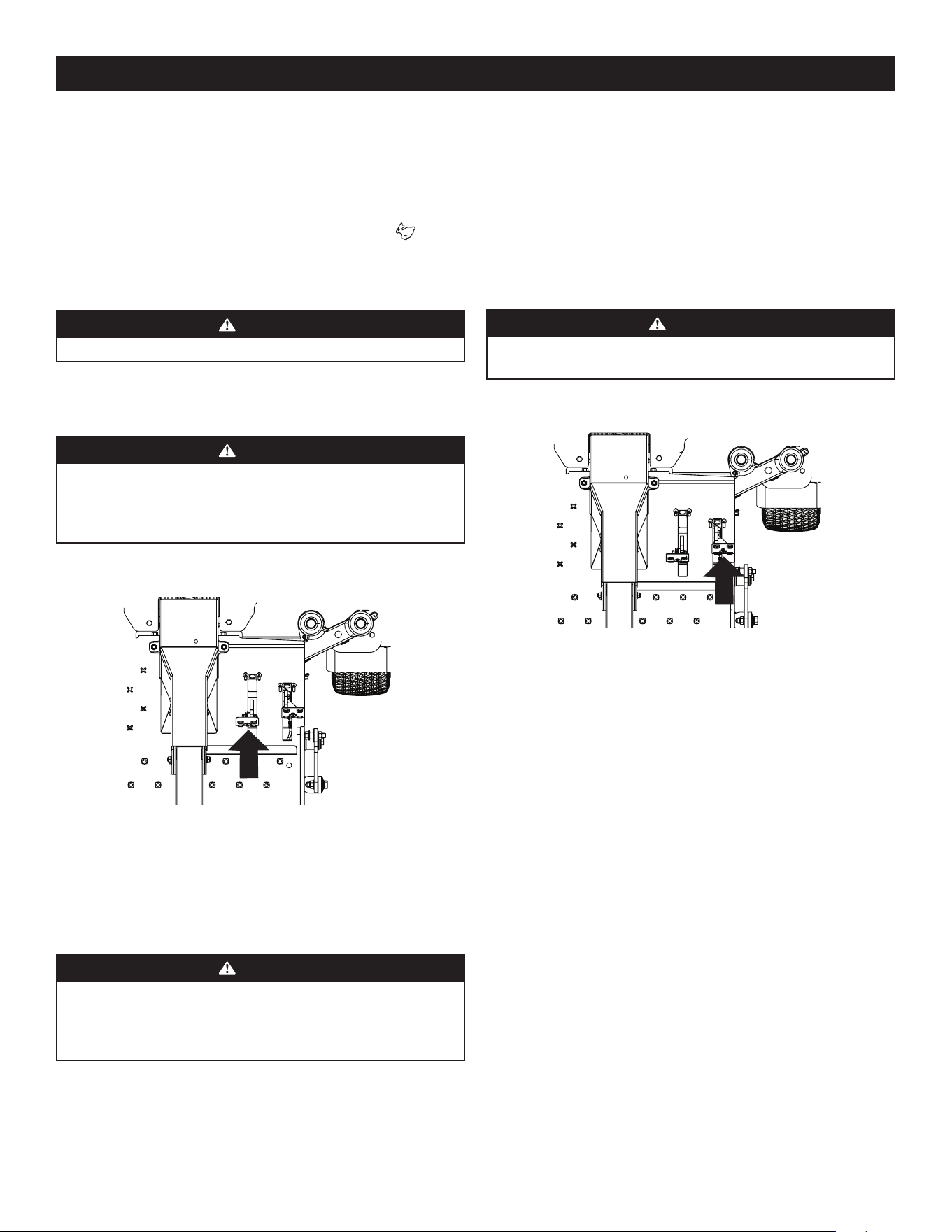
19
OPERATION
2. To turn to the right, turn the steering wheel clockwise (to the operator’s right).
3. The greater the distance the steering wheel is turned, the sharper the mower
will turn.
4. To execute a “pivot turn,” move the steering wheel so that the inside wheel is
angled at approximately 88° and the turn side tire will not rotate.
NOTE: Making a “pivot turn” on grass will greatly increase the potential for
defacement of the turf as well as potential damages to the traction surface and
the tire.
Driving the Mower in Reverse
WARNING
Always look behind and down on both sides of the mower before backing
up. Always look behind while traveling in the reverse direction.
1. Slowly push the reverse drive pedal forward. The mower will start to move in
the reverse direction. See Figure 24.
Figure 24
2. As the reverse drive pedal is pushed farther forward the speed of the mower
will increase.
3. To slow the mower release the reverse drive pedal to attain the desired speed,
or allow the pedal to return to the neutral position to stop the mower.
Turning While Driving Rearward
To turn the mower while driving rearward, use the steering wheel to turn in the
direction you wish to travel.
1. To turn to the left while traveling in reverse, turn the steering wheel clockwise
(to the operator’s right).
2. To turn to the right while traveling in reverse, turn the steering wheel counter-
clockwise (to the operator’s left).
3. The greater the distance the steering wheel is turned, the sharper the mower
will turn.
4. To execute a “pivot turn,” move the steering wheel so that the inside wheel is
angled at approximately 88° and the turn side tire will not rotate.
NOTE: Making a “pivot turn” on grass will greatly increase the potential for
defacement of the turf as well as potential damages to the traction surface and
the tire.
Executing a Zero Turn
1. A zero turn maneuver can be executed while the machine is moving in the
forward or reverse directions if the steering wheel is turned completely in the
one direction.
3. Adjust the operator’s seat to the most comfortable position that allows you to
operate the controls. Refer to the Set-Up section for instructions on adjusting
the seat.
4. Adjust the steering wheel tilt with the steering column adjustment lever.
5. Release the parking brake.
6. Move the throttle control lever (if equipped) forward to the FAST position.
NOTE: The mower’s engine is designed to run at full throttle, but when
performing a practice session the mower must be operated at less than full
throttle. This only applies to practice.
WARNING
Always maintain a firm grip on the steering wheel.
7. To drive the mower, firmly grasp the steering wheel with your right and left
hands and continue with Driving the Mower Forward.
Driving the Mower Forward
WARNING
Keep all movement of the drive pedals slow and smooth. Abrupt movement
of the pedals can affect the stability of the mower and could cause
the mower to flip over, which may result in serious injury or death to
the operator.
1. Slowly push the forward drive pedal forward. The mower will start to move
forward. See Figure 23.
Figure 23
2. As the forward drive pedal is pushed farther forward the speed of the mower
will increase.
3. To slow the mower, slowly release the forward drive pedal to attain the desired
speed, or allow pedal to return to the neutral position to stop the mower.
Turning the Mower While Driving Forward
WARNING
When reversing the direction of travel, performing gradual “U” turns where
possible is recommended. Sharper turns increase the possibility of turf
defacement, and could affect control of the mower. ALWAYS slow the mower
before making sharp turns.
To turn the mower while driving forward, use the steering wheel to turn in the
direction you wish to travel.
1. To turn to the left, turn the steering wheel counter-clockwise (to the
operator’s left).
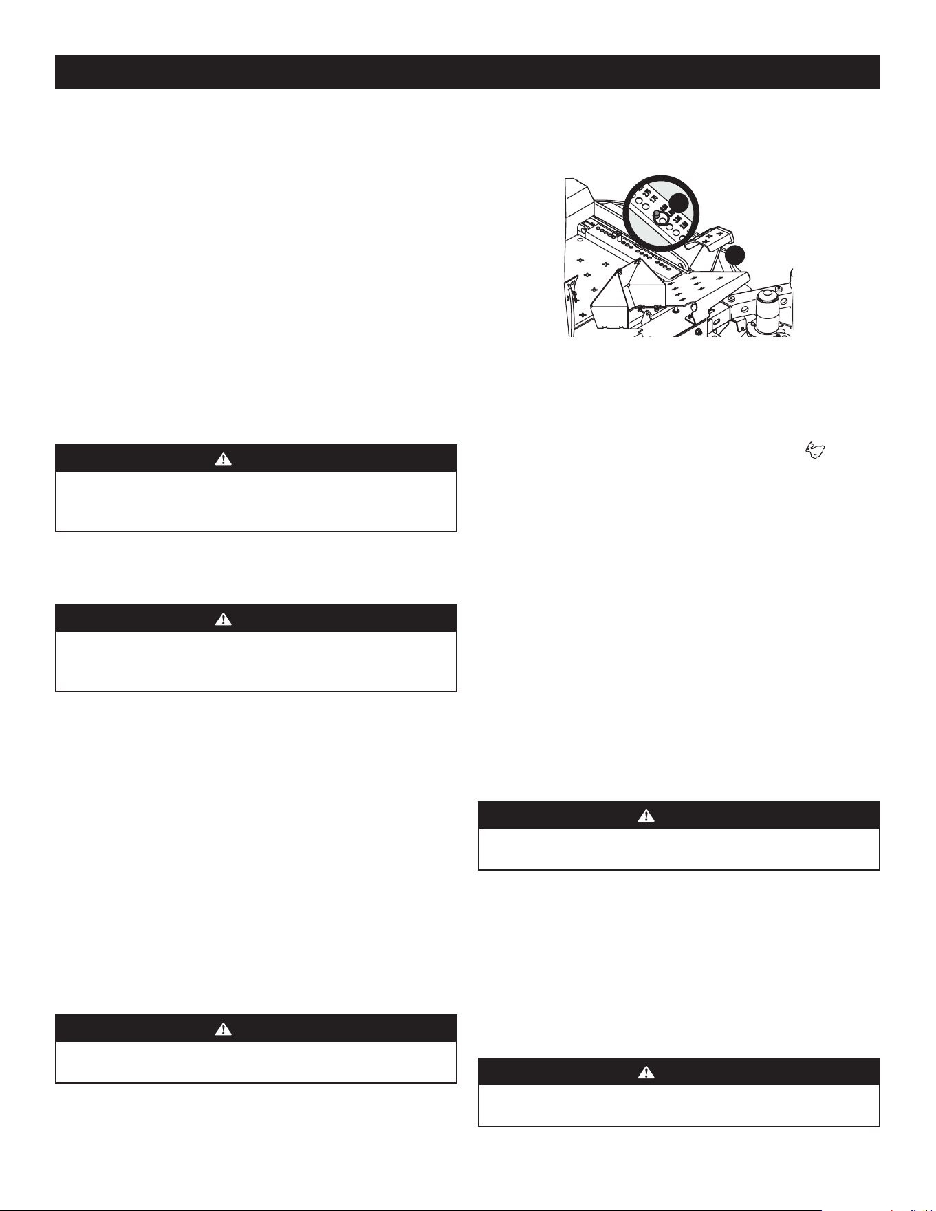
20
OPERATION
2. To turn clockwise when going forward, turn the steering wheel clockwise
and depress the forward drive pedal. Release the pedal and the machine
should stop turning. If the reverse drive pedal is depressed, the turn will
be counter-clockwise.
3. To turn counter-clockwise when going forward turn the steering wheel
counter-clockwise and depress the forward drive pedal. Release the pedal and
the machine should stop turning. If the reverse drive pedal is depressed, the
turn will be clockwise.
Stopping the Mower
1. Allow the forward and reverse drive pedals to return to the neutral position to
stop the motion of the mower.
2. Push the PTO knob downward to the disengaged position.
3. Use the deck lift pedal to raise the deck to its highest position.
4. If dismounting the machine, allow the drive pedals to return to the neutral
position, engage the parking brake, turn the ignition switch to OFF and remove
the key from the switch.
WARNING
Do not leave the seat of the mower without disengaging the PTO, moving
drive pedals to the neutral position engaging the parking brake. If leaving
the mower unattended, turn the ignition key OFF and remove.
Driving on Slopes
Refer to the slope gauge on the back cover to help determine slopes where you may
not operate safely.
WARNING
Do not operate on inclines with a slope in excess of 20°/35% (a rise of
approximately 4 feet every 10 feet). The machine could overturn and cause
serious injury.
1. Always drive across slopes, never up and down.
2. Avoid turning downhill if possible. Start at the bottom of a slope and work
upward. Always slow down before turning.
3. Use extra care and go slowly when turning downhill.
Operating the PTO knob
Operate the PTO knob as follows:
1. Move the throttle control lever (if equipped) to approximately the mid-
throttle position.
2. Pull the PTO knob switch upward to the ENGAGED position.
3. Advance the throttle lever to the operating speed (full engine speed).
4. The operator must remain in the mower seat at all times. If the operator should
leave the seat without turning off the power take-off switch, the mower’s
engine will shut off.
Using the Mower Deck
WARNING
Make certain the area to be mowed is free of debris, sticks, stones, wire, or
other objects that can be thrown by the rotating blades.
NOTE: Do not engage the mower deck when lowered in grass. Premature wear
and possible failure of the “V” belt and PTO clutch will result. Fully raise the
deck or move to a non-grassy area before engaging the mower deck.
1. Use the deck lift pedal (a) to raise the deck to its highest position, place the
clevis pin (b) attached to the mower into the desired index hole on the deck
height index, then slowly release the deck lift pedal (a). See Figure 25.
L
o
w
e
r
a
b
Figure 25
2. Mow across slopes, not up and down. If mowing a slope, start at bottom and
work upward to ensure turns are made uphill.
3. On the first pass pick a point on the opposite side of the area to be mowed.
4. Engage the PTO knob and move the throttle control to the FAST position.
5. Remove the clevis pin, raise the deck to the highest (transport) position, place
the clevis pin in the desired position and secure with the clevis pin. Lower the
mower deck to the desired height setting.
6. Slowly push the forward drive pedal forward to move the mower forward, and
keep the mower headed directly toward the alignment point.
NOTE: The speed of the mower will affect cut quality of the lawn. Mowing
at full speed will adversely affect a high quality cut lawn. Control the ground
speed with the drive pedals.
7. When approaching the other end of the strip, slow down or stop before
turning. A U-turn is recommended unless a pivot or zero turn is required.
8. Align the mower with an edge of the mowed strip and overlap
approximately 3”.
9. Direct the mower on each subsequent strip to align with a previously cut strip.
10. To prevent rutting or grooving of the turf, if possible, change the direction
that the strips are mowed by approximately 45° for the next and each
subsequent mowing.
WARNING
Be careful when crossing gravel paths or driveways. Disengage the PTO knob
and raise the deck to the highest/transport position before crossing.
NOTE: When stopping the mower for any reason while on a grass
surface, always:
a. Make sure the drive pedals are in neutral.
b. Engage the parking brake.
c. Shut engine off and remove the key.
d. Doing so will minimize the possibility of having your lawn ‘‘browned’’ by
hot exhaust from your mower’s running engine.
SUREPATH AUTO STEER SYSTEM
WARNING
Make certain the area to be mowed is free of debris, sticks, stones, wire, or
other objects that can be thrown by the rotating blades.
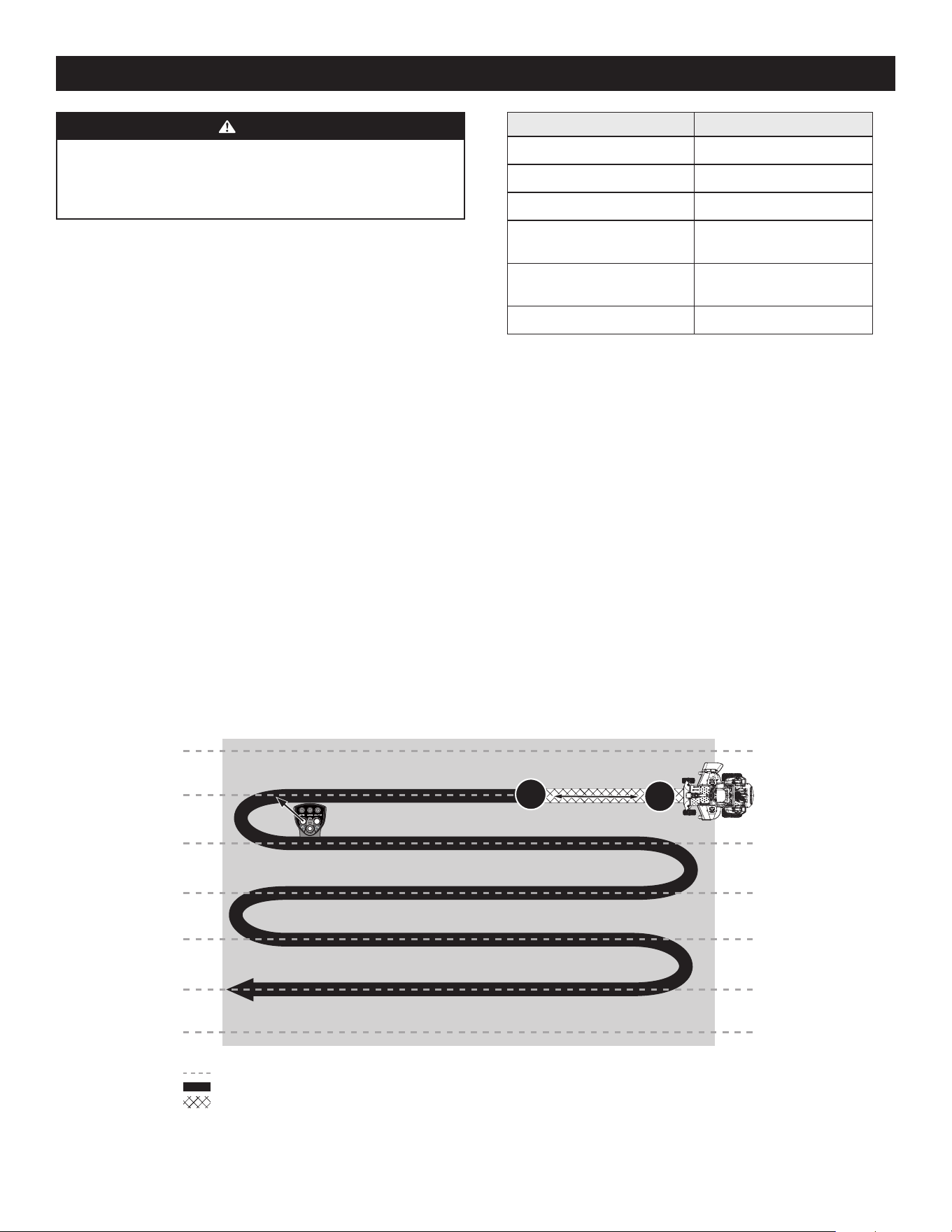
21
OPERATION
WARNING
The SurePath Auto Steer system will not detect any objects or obstructions
in the path of the cutting deck or the machine. Always operate the machine
with care and attention. Stop the machine immediately or manually steer
the machine around obstacles before resuming SurePath Auto Steer Mode.
The SurePath Auto Steer system uses GPS technology to semi-autonomously control
steering and turning capabilities to achieve consistent stripes, reduce turfing and
maximize mowing efficiency.
Initializing SurePath Auto Steer Mode
1. Start the mower. See instructions provided in Starting the Engine section.
2. Indicator/Warning Lights will flash blue while the SurePath Auto Steer system
is initializing.
3. Once the system has initialized, Indicator/Warning Lights will begin flashing
green. The SurePath Auto Steer system is actively searching for GPS signal.
IMPORTANT! Machine should be outdoors, away from large trees and
buildings in order to acquire signal.
NOTE: Signal acquisition will take approximately 90 seconds.
4. Once signal is acquired, Indicator/Warning Lights will turn solid green. The
mower is now ready for SurePath Auto Steer Mode. See Figure 26 for a list of
Indicator/Warning Light colors and descriptions.
Descriptions Indicator/Warning Light Colors
System Initializing Flashing Blue
Attempting to Acquire GPS Signal Flashing Green
†
GPS Signal Acquired Solid Green
Mower Speed too Fast for
SurePath Auto Steer Mode
Flashing Yellow
*
Grab and Turn Wheel to Override
SurePath Auto Steer Mode
Flashing Red
Software Update in Process Solid Yellow
#
*
Also indicates a button press ignored by the system
†
Periodic red ash indicates no cellular connectivity
#
See authorized dealer for more information
Figure 26
Setting the Mowing Line (SurePath Auto Steer Mode)
1. Start the mower. See instructions provided in Starting the Engine section.
NOTE: PTO does not need to be engaged to set mowing line.
2. Once indicators on the Indicator/Warning Lights are solid green, the system is
ready for SurePath Auto Steer Mode.
3. Set your mowing line by performing the following steps:
• Determine the first pass location, picking a point on the opposite side of the
area to be mowed.
• Drive in a straight line toward point chosen in the previous step and briefly
press the SET LINE/ENGAGE AUTO button on the Operator Control Panel to
set point A. See Figure 27. The LINE indicator will begin flashing green when
point A is set.
B*
A*
*
Left turn (as shown) or right turn*
SurePath Auto Steer Infinite Set Lines
SurePath Auto Steer Mowing
Manual Mowing
Press and Release
>10 yards (30 feet)
Figure 27
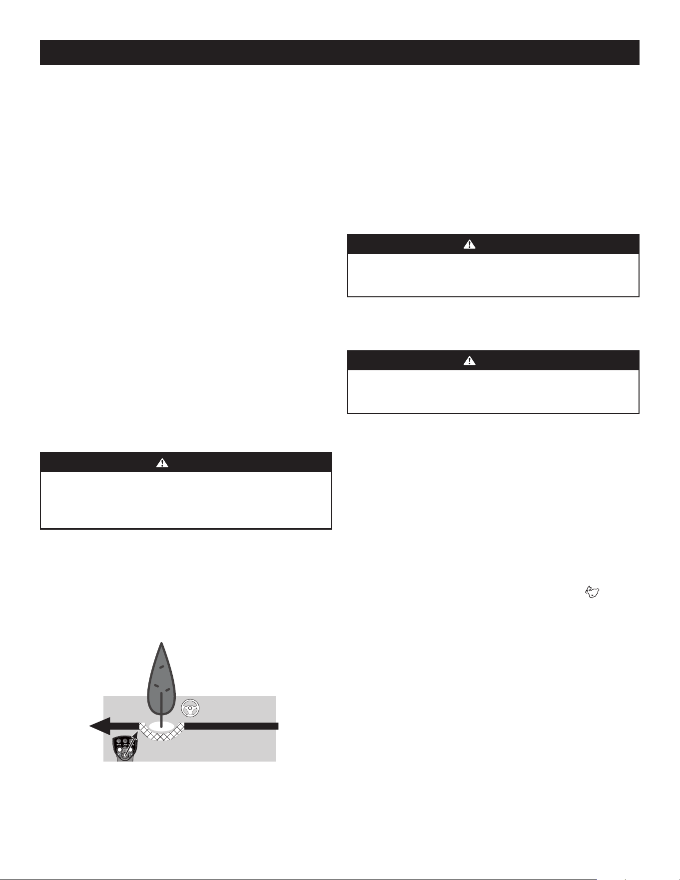
22
OPERATION
• Continue driving in a straight line, travel a minimum of 10 yards (30 feet), then
briefly press the SET LINE/ENGAGE AUTO button on the Operator Control Panel
again to set point B. See Figure 27 on page 21. The LINE and AUTO indicators
will turn solid green when points A and B are set.
NOTE: Once the AUTO Indicator/on the Operator Control Panel is solid green,
the system is activated for SurePath Auto Steer Mode and the operator should
let go of the steering wheel.
IMPORTANT! Setting the mowing line automatically shifts mower to SurePath Auto
Steer Mode.
Clearing the Mowing Line (SurePath Auto Steer Mode)
To reset the system and remove the saved points defining the mowing line:
1. Stop the mower.
2. Turn the PTO off.
3. Press and hold the SET LINE/ENGAGE AUTO button on the Operator Control
Panel for a minimum of 3 seconds.
NOTE: If SET LINE/ENGAGE AUTO button is not held for a minimum of 3 seconds,
the Indicator/Warning Lights will blink yellow once to indicate an invalid reset.
4. LINE indicator on the Operator Control Panel will turn off once points A and B
are cleared.
NOTE: Operator will need to reset points A and B prior to resuming SurePath
Auto Steer Mode. Refer to Setting the Mowing Line (SurePath Auto
Steer Mode).
NOTE: Clearing the mowing line will automatically return mower to
manual mode.
WARNING
Holding the SET LINE/ENGAGE AUTO button for less than 3 seconds will fail
to reset line and may shift the mower back into auto mode if preset lines
are still stored. Loss of control, property damage, personal injury, or death
may result.
Manual Override of SurePath Auto Steer Mode
To remove the mower from SurePath Auto Steer Mode, the operator should resume
control of the steering wheel and turn it slightly to either the right or left. This
will return the mower to manual mode. The AUTO indicator will be flashing. See
Figure 28.
To resume SurePath Auto Steer Mode, briefly press the SET LINE/ENGAGE AUTO
button on the Operator Control Panel. See Figure 28.
Manually steer
around obstacles
Briefly press SET LINE/ENGAGE
AUTO button to resume Auto Steer
Figure 28
NOTE: Do not hold the SET LINE/ENGAGE AUTO button down when resuming
SurePath Auto Steer Mode. Holding the button for 3 seconds or more will reset the
system, erasing the A and B points previously set.
Automatic Shut Off or GPM Signal Loss
If the GPM loses signal, the mower will return to manual mode. The following
sequence will occur:
1. The Indicator/Warning Lights on the Light Module will flash red and the system
will stop steering the mower.
2. The operator must resume control of the steering wheel and turn it slightly to
either the right or left to return to manual mode.
3. Once GPS signal has been reacquired, the Indicator/Warning Lights will be solid
green. Briefly press the SET LINE/ENGAGE AUTO button to resume SurePath
Auto Steer Mode.
WARNING
If the SurePath Auto Steer system malfunctions, stop using the machine or
disable the system and have it repaired by an authorized servicing dealer as
soon as possible.
NOTE: If the SurePath Auto Steer system malfunctions see Troubleshooting in the
Product Care section or contact an authorized service provider.
Using the Mower Deck (SurePath Auto Steer Mode)
WARNING
To avoid personal injury to you or others, always use caution and be aware
of your surroundings when using the SurePath Auto Steer Mode. Stop the
machine immediately if anyone enters the area.
NOTE: Operator is always in control of the mower’s speed and braking.
1. Use the deck lift pedal (a) to raise the deck to its highest position, place the
clevis pin (b) attached to the mower into the desired index hole on the deck
height index, then slowly release the deck lift pedal (a). Refer to Figure 25 on
page 20.
2. Mow across slopes, not up and down. If mowing a slope, start at bottom and
work upward to ensure turns are made uphill.
3. To establish your mowing line refer to Setting the Mowing Line (SurePath Auto
Steer Mode) section.
IMPORTANT! Setting the mowing line automatically shifts mower to SurePath Auto
Steer Mode.
4. Engage the PTO knob and move the throttle control to the FAST position.
5. To move forward, slowly push the forward drive pedal forward. The SurePath
Auto Steer system will keep the mower aligned with the preset mowing line.
NOTE: The speed of the mower will affect cut quality of the lawn. Mowing
at full speed will adversely affect a high quality cut lawn. Control the ground
speed with the drive pedals.
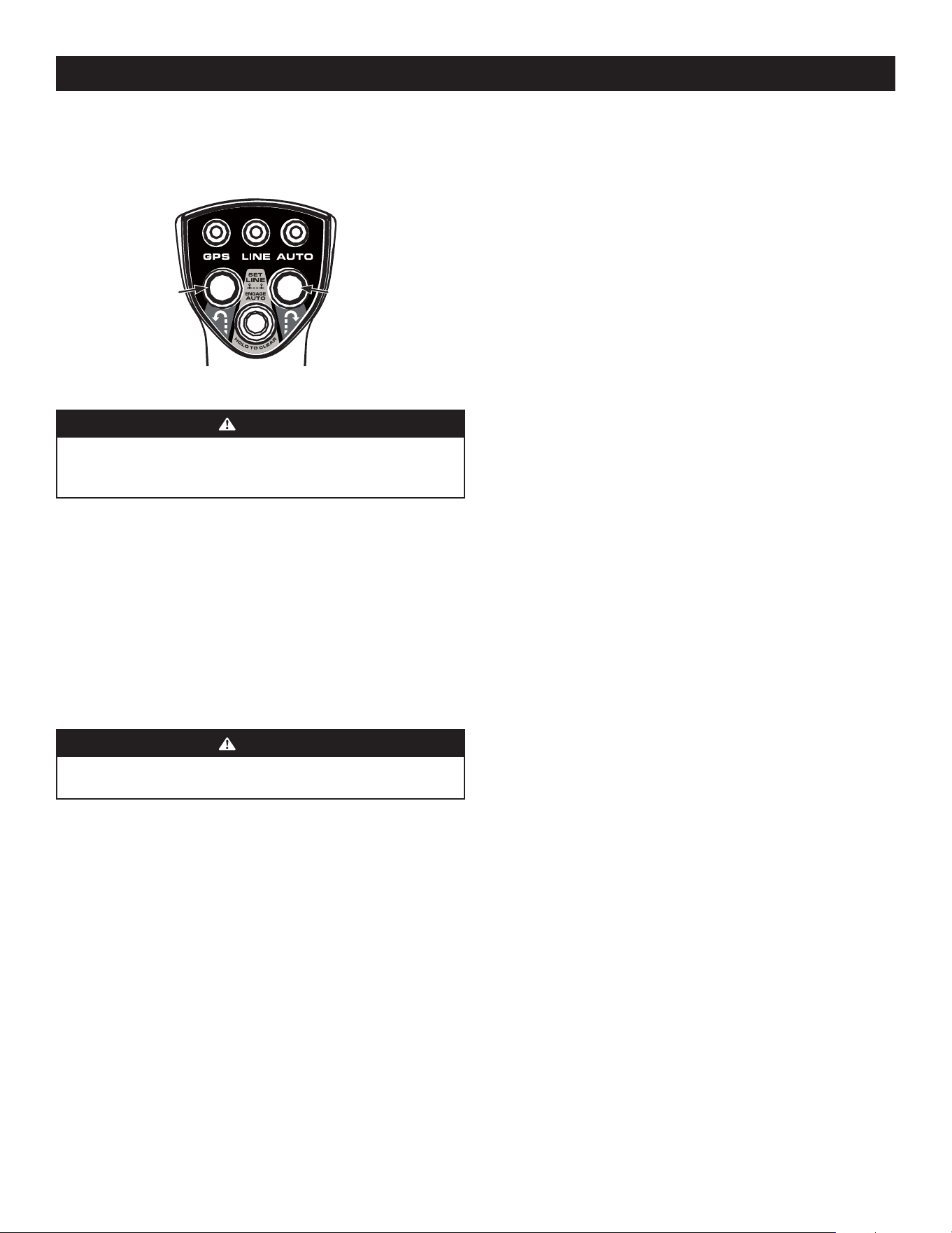
23
OPERATION
Disabling the SurePath Auto Steer System
To prevent unauthorized use, or if the system malfunctions, the SurePath Auto Steer
system can be disabled by removing the GPM fuse (labeled F5:GPM in the fuse box
located under the operator’s seat).
Forced Striping
The SurePath Auto Steer system will force side-by-side passes to be cut in opposite
directions. This setting can be adjusted by contacting an authorized service center.
Calibration
See Calibration in the Product Care section for information regarding calibrating the
SurePath Auto Steer system.
MOWER CUTTING BLADES
The blades normally factory installed on a mower afford the best grass cutting
performance on the majority of grasses and mowing conditions; however, there
will be occasions whereby the grass type, stage of grass growth, soil conditions and
weather conditions will require different cutting blade types. Since the mower decks
are designed so that over-lap of the cutting blades generally exceed 1.5”, there is no
need for orientation of one cutting blade to an adjacent blade (i.e., the blades do not
need to be “timed” nor synchronized).
Hi-lift — These are generally the best cutting blades for most grasses and mowing
conditions. The Hi-Lift blades are the factory installed blades on these mowers.
These blades will provide extra “lift” for the thinner leaf grasses, will handle lush
grasses and will provide maximum grass and debris discharge. These blades are
generally required for material collection systems. More horsepower is required
for these blades when compared to others, and they generally produce the highest
noise levels.
Medium-lift — These blades require less horsepower than the Hi-lift, and they
generally work well in wider leaf grasses and some mulch applications.
Low-lift — These blades require less horsepower than Hi-lift and Medium-lift
blades, and they generally work best with wide leaf grasses, sparse grass growth
and sandy soil conditions. They produce the lowest noise levels. Low-lift blades are
configured without offset, and with a maximum amount of sharpened cutting edge.
Mulch — These blades are generally designed for use in cutting decks equipped
with mulch baffles. The shape of the blade generally produces higher turbulence
in order that the grass can be repeatedly cut and re-cut into smaller pieces. These
blades generally require more horsepower than other blades. Mulch blades work
best when the grasses are cut at the highest levels, minimal lengths of grasses are
removed and grass conditions are generally dry.
NOTE: Refer to the Replacement Parts and Accessories section for a list of
part numbers.
6. When approaching the other end of the strip, release pressure on the forward
drive pedal slightly to slow down before initiating a right or left zero turn.
Briefly press the right or left turn button on the Operator Control Panel. See
Figure 29.
Left Zero
Turn
Right Zero
Turn
Figure 29
WARNING
Do not attempt to make a turn at high speed when using SurePath Auto
Steer Mode. The system will make smoother and more accurate turns at
lower speeds.
NOTE: Left and right turn buttons will only function if SurePath Auto Steer Mode has
been activated.
NOTE: The SurePath Auto Steer system will make smoother and more accurate turns
at lower speeds, and allow it to more easily pick up and maintain the signal for the
next parallel line to be followed.
7. Make sure mower is realigned with mowing line before accelerating.
8. Repeat Steps 5-7 to continue cutting parallel lines in SurePath Auto Steer Mode.
IMPORTANT! To prevent rutting or grooving of the turf, if possible, change the
direction that the strips are mowed by approximately 45° for the next and each
subsequent mowing session.
WARNING
Be careful when crossing gravel paths or driveways. Disengage the PTO knob
and raise the deck to the highest/transport position before crossing.
NOTE: When stopping the mower for any reason while on a grass
surface, always:
a. Make sure the drive pedals are in neutral.
b. Engage the parking brake.
c. Shut engine off and remove the key.
d. Doing so will minimize the possibility of having your lawn ‘‘browned’’ by
hot exhaust from your mower’s running engine.
9. Release pressure on forward drive pedal slightly before initiating right or left
zero turn.
10. Make sure mower is realigned with mowing line before accelerating.

24
OPERATION
RECONFIGURABLE MOWER
Inner Baffle Discharge Baffle Cutting Blades Gauge Wheels Front Roller Rear Rollers
Standard set-up Installed Installed Hi-lift Low = 3 to 5” Low = 3 to 5” Low = 3 to 5”
Stems (Dandelion, Bahia,
Buckhorn, etc.)
Removed Installed Hi-lift
High = 1 to 2-1⁄2”
Low = 3 to 5”
High = 1 to 2-1⁄2”
Low = 3 to 5”
High = 1 to 2-1⁄2”
Low = 3 to 5”
Very lush &/or tall grass Removed Installed Hi-lift
High = 1 to 2-1⁄2”
Low = 3 to 5”
High = 1 to 2-1⁄2”
Low = 3 to 5”
High = 1 to 2-1⁄2”
Low = 3 to 5”
Low cut height (1 to 2”) Installed Installed Low-lift High = 1 to 2-1⁄2” High = 1 to 2-1⁄2” High = 1 to 2-1⁄2”
Mulch Installed Removed Hi-lift/Mulch
High = 1 to 2-1⁄2”
Low = 3 to 5”
High = 1 to 2-1⁄2”
Low = 3 to 5”
High = 1 to 2-1⁄2”
Low = 3 to 5”
Material collection Installed Installed Hi-lift
High = 1 to 2-1⁄2”
Low = 3 to 5”
High = 1 to 2-1⁄2”
Low = 3 to 5”
High = 1 to 2-1⁄2”
Low = 3 to 5”
Abrasive (sandy), dry Removed Installed Low-lift
High = 1 to 2-1⁄2”
Low = 3 to 5”
High = 1 to 2-1⁄2”
Low = 3 to 5”
High = 1 to 2-1⁄2”
Low = 3 to 5”
Wet Installed Installed Hi-lift
High = 1 to 2-1⁄2”
Low = 3 to 5”
High = 1 to 2-1⁄2”
Low = 3 to 5”
High = 1 to 2-1⁄2”
Low = 3 to 5”
Table Notes: This table is a general outline of suggested settings, mowing conditions may vary.
Inner Baffle: The inner baffle regulates grass discharge. Remove the inner baffle for high-volume grass and install the inner baffle for precision cutting.
Discharge Baffle: The discharge baffle enhances the grass discharge pattern. The discharge baffle reduces clumping and should be removed for mulching.
Cutting Blades: The cutting blades cut grass, create grass lift and discharge grass through the discharge chute.
Gauge Wheels: The gauge wheels reduce scalping, help with precision cutting and reduce turf defacement during turns.
Front Roller (if equipped): The front roller reduces scalping, helps with precision cutting and reduces turf defacement during turns.
Rear Rollers: The rear rollers reduce scalping and gives grass a striped appearance.
NOTE: To avoid damaging grass, no more than 1/3 of the grass height should be removed during a single cutting (i.e. if the grass is 6” tall, cut it to 4”).

25
PRODUCT CAREPRODUCT CARE
Before Each Use Every 50 Hours Every 500 Hours After Mowing
Check Gasoline Level
Check Hydraulic Hoses for Leaks
Check Tires & Tire Pressure
Check Deck, Mower & Hydro Drive Belts
Check Blades & Blade Bolt Tightness
Check Safety Switches for Proper Operation
Check Fluid Level in Transmission Oil Expansion Reservoir
Check/Clean Engine Intake Screens & Cooling Fans *
Check/Clean Exhaust Manifold, Muffler Pipe & Muffler Shields *
Check/Clean Top & Underside of Deck, Under & Around Spindle Covers & Belt Area *
Check/Clean Around Fuses, Wiring & Wiring Harnesses *
Check/Clean Around Transmission, Axle & Fans *
Blow Out/Clean Pump Control Area Under Floor Pan
Blow Out/Clean Pedal Control Area Under Foot Rest
Lubricate Wear Points (see chart)
Clean Engine Cooling Fins & External Surfaces *
Change Hydrostatic Fluid & Filter in Transaxles †
† — After first 300 hours, change hydrostatic fluid and filter in transaxles
* — Perform more frequently under dusty conditions
MAINTENANCE SCHEDULE
WARNING
Before performing any type of maintenance/service, disengage all controls
and stop the engine. Wait until all moving parts have come to a complete
stop. Disconnect the spark plug wire(s) and negative battery cable to
prevent unintended starting. Always wear safety glasses during operation
or while performing any adjustments or repairs.
Follow the Maintenance Schedule given below. This chart describes service
guidelines only.
Refer to the Engine Operator’s Manual for engine maintenance items listed in the
table below.
NOTE: This Operator’s Manual covers several models. Mower features may vary by
model. Not all features in this manual are applicable to all mower models and the
mower depicted may differ from yours.
WARNING
Before performing any maintenance or repairs, disengage the PTO, move
the drive pedals to the neutral position engaging the parking brake, stop
the engine, and remove the key to prevent unintended starting.
POST-OPERATION MOWER CARE
After each operation of the mower, the following procedures should be implemented
to extend the life of your mower and ensure safe operating conditions.
DANGER
Failure to follow these recommendations may result in serious injury to
yourself or others and may cause damage to the mower.
Cleaning the Underside of the Deck
Rinse grass clippings from the deck’s underside and prevent the buildup of
corrosive chemicals.
WARNING
Make certain the mower’s discharge chute is directed AWAY from people,
your house, garage, parked cars, etc.
1. Disengage the PTO, set the parking brake and stop the engine.
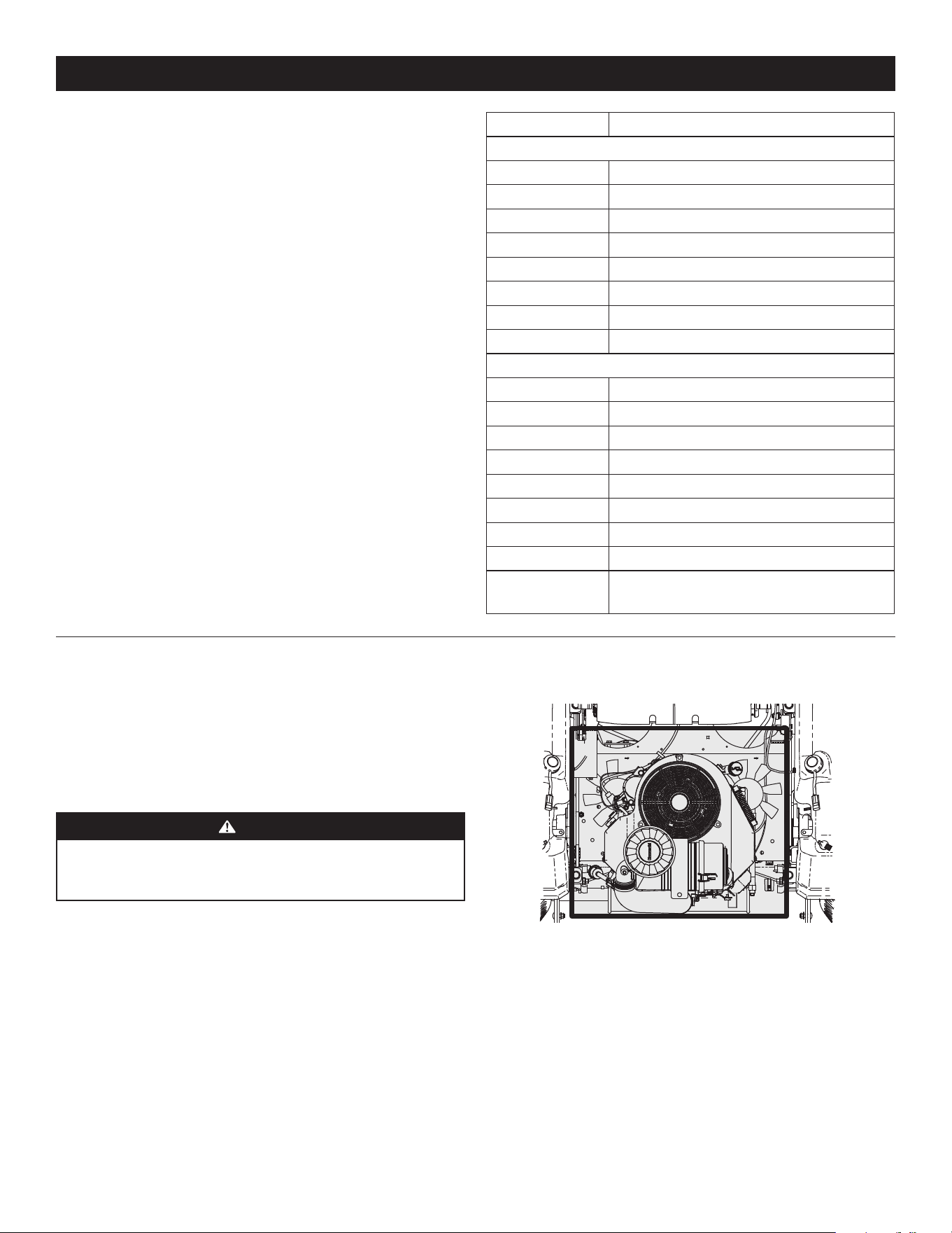
26
PRODUCT CARE
2. Use a hose to spray the underside of the deck.
NOTE: Make sure that the hose is not routed under the deck and is clear of all
moving parts.
3. After cleaning your deck, return to the operator’s position and engage the PTO.
Keep the deck running for a minimum of two minutes, allowing the underside
of the deck to thoroughly dry.
Cleaning the Mower
WARNING
If the mower has been recently run, the engine, muffler, and surrounding
metal surfaces will be hot and can cause burns to the skin. Let the engine
cool for at least five minutes. Exercise caution to avoid burns.
Your mower should be cleaned after each use and under certain conditions, i.e. dry
conditions and/or mulching situations, additional cleaning may be necessary.
One of the best ways to keep your mower running efficiently and to reduce fire risk
is to regularly remove debris buildup from the mower. Follow the recommendations
below and contact your authorized dealer with any questions.
• Allow the machine to cool in an open area before cleaning.
• Do not use water on any part of the mower except the underside of the cutting
deck. Doing so can cause damage to the mower’s spindle bearings, electrical
system and engine, leading to premature failures. The use of compressed air
and/or leaf blower will help keep the mower clean.
• Clean around the exhaust manifold, fuses, all wiring and harnesses, muffler
pipe, muffler shield, engine intake screens and cooling fins, etc. See Figure 30.
Figure 30
OIL CHART
Apply a few drops of SAE engine oil, grease or use a spray lubricant. Apply the oil
to both sides of pivot points. Wipe off any excess. Start engine and operate mower
briefly to ensure that oil spreads evenly.
Engine Oil
• Shell Rotella® T Triple Protection™ 15W40
• Shell Rimula® 15W40
• Reference your Engine Operator’s Manual for other approved options
Hydrostatic Fluid
• Drive System Fluid Plus (Shell TT-SB)
• Castrol™ (Syntec®) Edge™ 5W50
General Purpose Lubrication: Use any NLGI Grade 2 multi-purpose grease. Shell
Albida EP2 is recommended. Shell Albida EP 2 is a red-colored multi-purpose grease
designed for heavy-duty bearing applications. It has high base oil viscosity for
mechanical stability, has been formulated for high load, low-speed applications and
has excellent lubrication and corrosion protection.
Number of Oil Points Description
DAILY
4 Deck Suspension Pivots
4 Height Adjustment Turnbuckle Clevis Pin
2 Height Adjustment Handle Pivots
2 Height Adjustment Stop Pivots
2 Deck Lift Linkage Pivots
2 Transport Handle Pivots
1 Transport Handle Pin
2 Deck Frame Up-and-Down Pivots
WEEKLY
1 Seat Hinge
2 Speed Control Linkage Rod End Bearings
2 Pump Control Lever Pivots
1 Brake Lever Pivot Clevis Pin
1 Brake Lever Control Rod Pivot
1 Brake Control Rod Swivel Joint
4 Brake Rod Clevis Pins
2 Brake Shaft Assembly Pivots
2 Grass Collection System Lid Hinges
(If mower is so equipped)
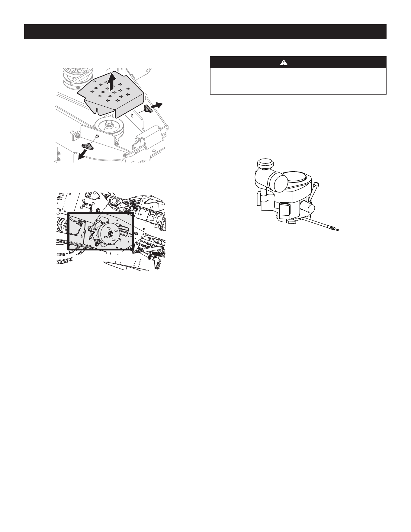
27
PRODUCT CARE
CHANGING THE ENGINE OIL
WARNING
If the engine has been recently run, the engine, muffler, and surrounding
metal surfaces will be hot and can cause burns to the skin. Exercise caution
to avoid burns.
Maintain oil level as instructed in Engine Operator’s Manual. Be careful not to spill oil
on any of the belts.
To complete an oil change, proceed as follows:
1. Run the engine for a short time to warm the engine oil. The oil will flow more
freely and carry away more impurities. Use care to avoid burns from hot oil.
2. Locate the oil drain hose on the engine. See Figure 33.
Figure 33
3. Remove the hose from the clip securing it to the frame.
4. Route the free end of the oil drain hose toward an appropriate oil collection
container with at least a 2.5 quart capacity, to collect the used oil.
NOTE: Avoid getting oil on the muffler when draining.
5. While holding the free end of the oil drain hose over the oil collection container,
unscrew the square-head hose plug from the end of the hose. See Figure 33.
Drain the engine oil into the collection container.
6. Remove the oil filter to make sure all the oil is drained.
7. After draining the oil, wipe any residual oil from the oil drain hose. Thread the
square head plug into the drain hose fitting and fully tighten the plug.
8. Replace the oil filter and refill the engine with new oil as instructed in
the Engine Operator’s Manual. Refer to the Engine Operator’s Manual for
information regarding the volume and weight of engine oil.
9. Place the hose back into the clip securing it to the frame.
Lubrication
Periodically lubricate all pivot points with a quality lubricating oil.
Tires
Check the tire air pressure after every 50 hours of operation or weekly. Keep the
tires inflated to the recommended pressures. Improper inflation will shorten the
tire service life and produce an uneven cut. See the tire side wall for proper inflation
pressures. Observe the following guidelines:
• Do not inflate a tire above the maximum pressure shown on the sidewall of
the tire.
• Do not reinflate a tire that has been run flat or seriously under-inflated. Have it
inspected and serviced by a qualified tire mechanic.
• Clean the top of the mower deck, under the spindle covers and belt area. See
Figure 31.
Figure 31
• Clean around and near the transmission, axle and the fan area. See Figure 32.
Wheel Not Shown For Clarity
Figure 32
Storing the Mower
• Allow the machine to cool in an open area before storing.
• Do not park the mower near any flammable materials (wood, cloth or
chemicals) or any open flames or other potential source of ignition (furnace,
water heater or any other type of heater).
• Remove all combustible materials from the mower before storing. Empty cargo
boxes, grass catchers or containers.
• Always shut off fuel flow when storing or transporting if mower is equipped
with a fuel shutoff.
• Check the fuel system (lines, tank, cap and fittings) frequently for cracks or
leaks. Repair and clean as necessary.
Calibration
The SurePath Auto Steer system will need to be calibrated in the
following circumstances:
• Major front end maintenance or replacement occurs.
• GPM or complete steering column is replaced.
Please contact an authorized service dealer for more information regarding
system calibration.
MAINTENANCE
Engine
Refer to the Engine Operator’s Manual for all engine maintenance intervals,
procedures, specifications and instructions.
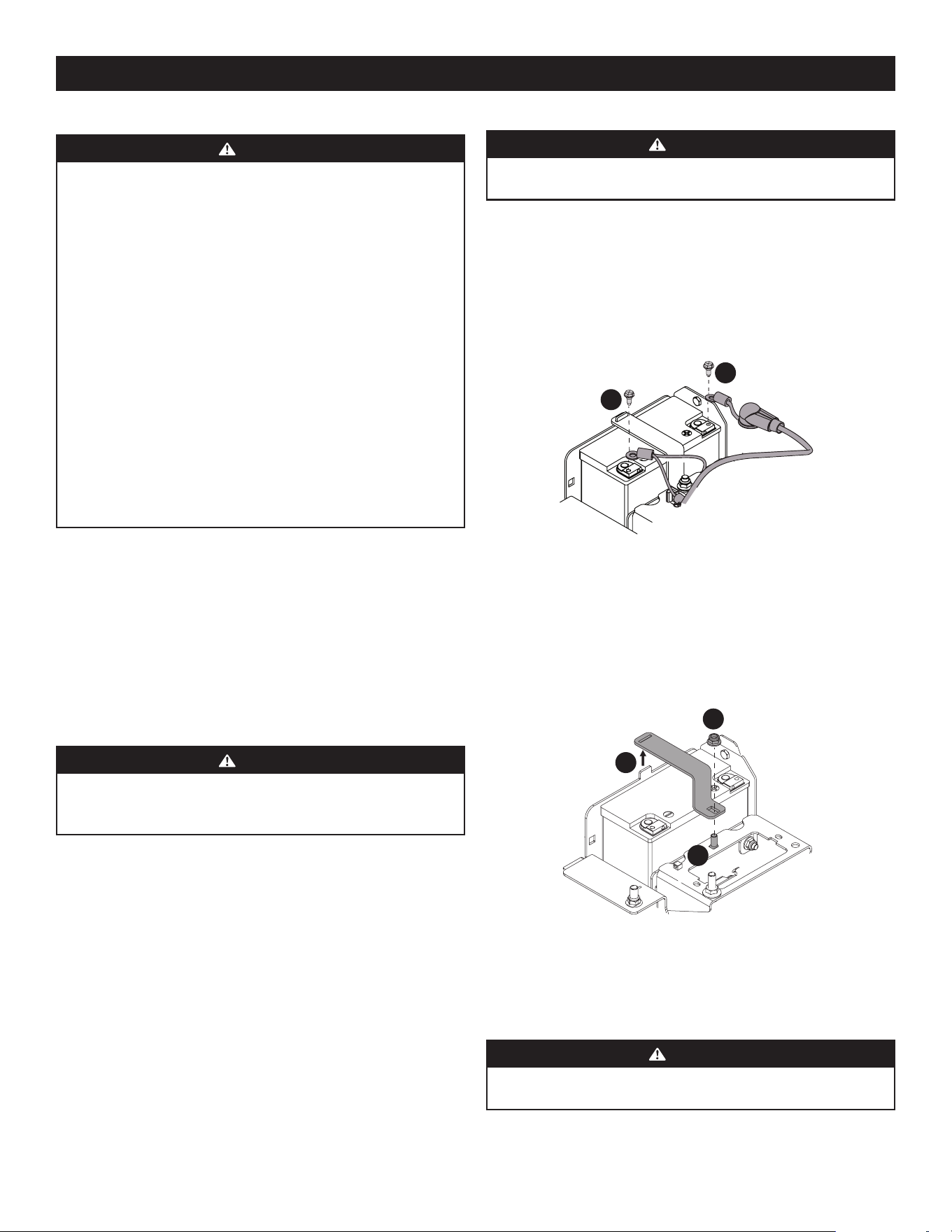
28
PRODUCT CARE
Battery Information
WARNING
Should battery acid accidentally splatter into the eyes or onto the skin,
rinse the affected area immediately with clean cold water. Seek prompt
medical attention.
If acid spills on clothing, first dilute it with clean water, then neutralize with
a solution of ammonia/water or baking soda/water.
NEVER connect (or disconnect) battery charger clips to the battery while the
charger is turned on, as it can cause sparks.
Keep all sources of ignition (cigarettes, matches, lighters) away from the
battery. The gas generated during charging can be combustible.
As a further precaution, only charge the battery in a well ventilated area.
Always shield eyes and protect skin and clothing when working
near batteries.
Batteries contain sulfuric acid and may emit explosive gases. Use extreme
caution when handling batteries. Keep batteries out of the reach
of children.
The battery may present a risk of fire or chemical burn if misused. Do not
open, disassemble, overheat, or incinerate the battery.
BATTERY MAINTENANCE
• The battery is filled with battery acid and then sealed at the factory. However,
even a “maintenance free” battery requires some maintenance to ensure its
proper life cycle.
• Spray the terminals and exposed wire with a battery terminal sealer, or
coat the terminals with a thin coat of grease or petroleum jelly, to protect
against corrosion.
• Always keep the battery cables and terminals clean and free of corrosion.
• Some models are equipped with a battery containing a liquid electrolyte.
Handle the battery with care and avoid tipping to prevent leakage.
WARNING
Batteries contain sulfuric acid and may emit explosive gases. Use extreme
caution when handling batteries. Keep batteries out of the reach
of children.
BATTERY STORAGE
1. When storing the mower for extended periods, disconnect the negative battery
cable. It is not necessary to remove the battery.
2. All batteries discharge during storage. Keep the exterior of the battery clean,
especially the top. A dirty battery will discharge more rapidly.
3. The battery must be stored with a full charge. A discharged battery can freeze
sooner than a charged battery. A fully charged battery will store longer in cold
temperatures than hot.
4. Recharge the battery before returning to service. Although the mower may
start, the engine charging system may not fully recharge the battery.
REMOVING THE BATTERY
WARNING
Battery posts, terminals, and related accessories contain lead and lead
compounds. Wash hands after handling.
1. Flip the seat all the way forward.
2. Remove the hex screw securing the black negative battery lead (a) to the
negative battery post (marked NEG). Move the cable away from the negative
battery post. See Figure 34.
3. Remove the hex screw securing the red positive battery lead (b) to the positive
battery post (marked POS). Move the cable away from the positive battery
post. See Figure 34.
a
b
Figure 34
4. Locate and hold the carriage bolt (a) at the front of the battery bracket (c) to
prevent it from falling. See Figure 35.
5. Remove the hex lock nut (b) securing the battery bracket (c) in place. Save the
carriage bolt and hex lock nut for later reinstallation. See Figure 35.
6. Lift the battery bracket (c) off of the tab at the left side of the battery
compartment and save for later reinstallation. See Figure 35.
a
b
c
Figure 35
Using the Transmission Bypass Levers
If for any reason the mower will not drive or you wish to move the mower, the two
hydrostatic transmissions are equipped with a bypass rod that will allow you to
manually move the mower short distances.
WARNING
Do not tow the mower, even with the bypass rod engaged. Serious
transmission damage will result from doing so.
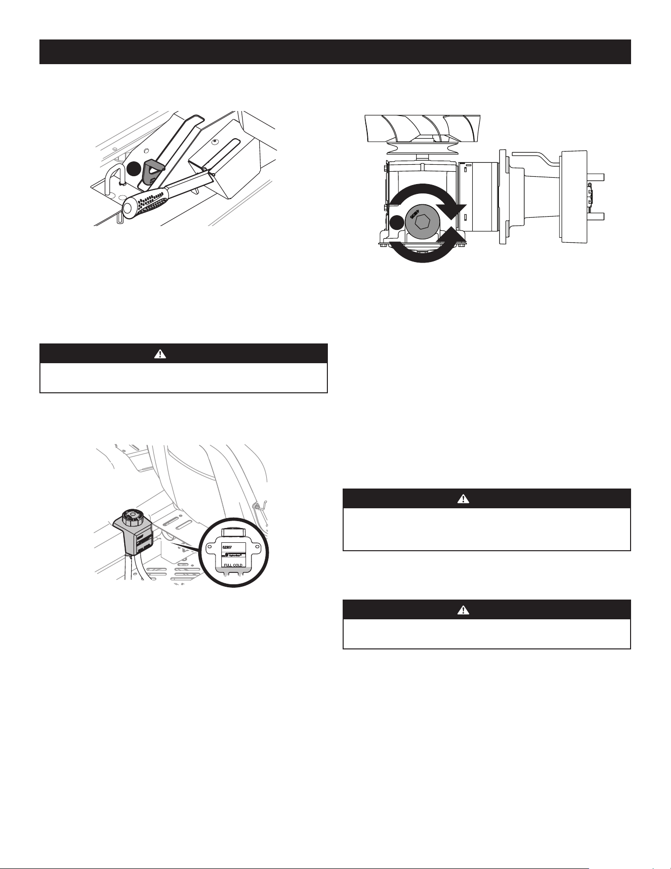
29
PRODUCT CARE
1. Engage the transmission bypass valves by pulling the bypass lever (a) upward
and all the way back. See Figure 36.
a
Figure 36
2. To release the bypass lever (a), push the lever forward.
Hydrostatic Transmission
The 900 series are equipped with dual integrated hydrostatic pumps/transaxles that
are equipped with a transmission oil expansion reservoir. Under normal operating
conditions, the oil level in the expansion reservoir does not need to be checked and
no additional oil is needed. If checking the reservoir oil level, proceed as follows:
WARNING
Check the oil level ONLY before starting the mower when the transmission
oil is fully cooled.
1. Pivot the operator’s seat forward and clean the reservoir cap and the area
around the cap to prevent debris from contaminating the transmission oil. See
Figure 37.
Figure 37
2. Turn the reservoir cap counter-clockwise to remove, then check the oil level
in the reservoir. Oil should be visible at the bottom of the cup, but the oil
level must NOT be above the “FULL COLD” line. See Figure 37. DO NOT FILL
THE RESERVOIR.
3. If necessary to add oil because of some type of leakage, add only enough oil to
bring the level to the “FULL COLD” line. Reinstall the cap and fully tighten.
NOTE: Prior to the initial operation of the mower, the oil level in the reservoir
may be slightly higher than the maximum due to air in the oil lines. Operation
of the mower will eventually purge the air from the lines and the oil level will
settle to the maximum.
To change the transmission oil:
1. Remove the cap from the transmission oil expansion reservoir.
2. Place a suitable container under the drain plug (a) on the transmission. Remove
the drain plug (a) and allow the transmission oil to drain. See Figure 38.
a
Figure 38
3. Using a pair of needle-nose pliers or a magnet remove the filter.
4. Replace the filter and drain plug (torque to 115-135 in-lbs) and fill through the
expansion reservoir slowly until the “FULL COLD” line. Allow the transmission
oil to move through the system and top off as necessary.
5. Replace the cap and fully tighten.
Mower Storage
If your mower is not going to be operated for an extended period of time (30 days
to approximately six months), the mower should be prepared for storage. Store the
mower in a dry and protected location. If stored outside, cover the mower (including
the tires) to protect it from the elements. The procedures outlined below should be
performed whenever the mower is placed in storage.
1. Change the engine oil and filter following the instructions provided in the
Engine Operator’s Manual packed with this manual.
WARNING
Never store the mower with fuel in the tank indoors or in poorly ventilated
enclosures, where fuel fumes may reach an open flame, spark, or pilot light
as on a furnace, water heater, clothes dryer, etc.
a. To prevent gum deposits from forming inside the engine’s carburetor
and causing possible malfunction of the engine, use a fuel stabilizer or
completely empty the fuel system for storage between 30 and 90 days:
WARNING
Fuel left in the fuel tank deteriorates and will cause serious
starting problems.
• Read the product manufacturer’s instructions and recommendations.
• Add to clean, fresh gasoline the correct amount of stabilizer for the
capacity of the fuel system.
• Fill the fuel tank with treated fuel and run the engine for 2-3 minutes
to get stabilized fuel into the carburetor.
b. Emptying the fuel system for storage of more than 90 days:
• Prior to putting the mower in storage, monitor fuel consumption
with the goal of running the fuel tank empty.
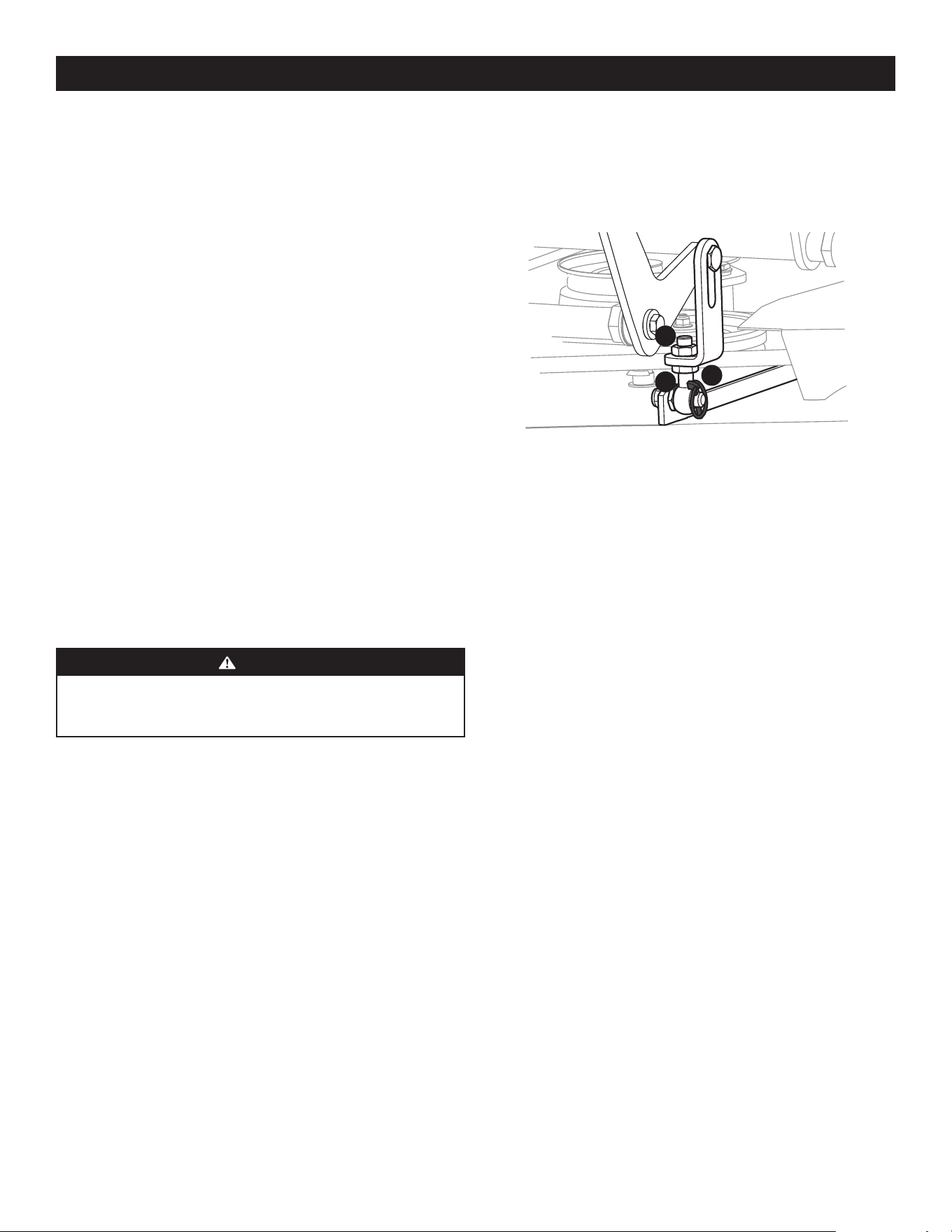
30
PRODUCT CARE
3. Adjust the eyebolt (a) at the left front of the deck so that the blade-to-ground
height at the right outside blade tip matches that of the left outside blade tip.
This is done by loosening the jam nuts (b) on the eyebolt (a) and tightening the
upper jam nut (b) to raise the deck and loosening the jam nut (b) to lower the
deck. The right outer blade tip height is fixed by the right, front eyebolt (a) so
you must adjust the left outer tip to match it. See Figure 39.
a
b
b
Figure 39
4. Once the proper adjustment is made, re-tighten the jam nuts (b).
FRONT-TO-BACK LEVELING
1. Park the mower on a flat paved surface, engage the parking brake, shut off the
engine, remove the key from the ignition switch, and disconnect the spark plug
wires. Using the deck lift pedal position the mowing deck into the 4” height of
cut position (The 4” height of cut position is recommended in order for one to
see and obtain a measurement. Any height of cut position is acceptable as long
as a proper measurement can be taken.) and rotate both outside blades so that
they are parallel with the mower.
2. Measure the blade-to-ground height at the right rear blade tip. Again, be sure
to measure the blade tip at the rear of the right blade when aligned along
the mower centerline. The blade-to-ground height at the rear of the blade
tip should be 1/8” to 1/4” higher than the front tip. This is referred to as blade
pitch. The same height difference should be true for the left blade, measured
front and back. The pitch should not exceed 1/16” if cut height is below 1-1/2”.
3. Loosen the jam nuts (b) at the rear left and right of the deck eyebolts (a). Refer
to Figure 39.
4. Start at the rear right to raise the rear of the deck, tighten the upper jam nut (b)
to raise the deck or loosen the upper jam nut (b) to lower the rear of the deck.
Refer to Figure 39.
5. Adjust the jam nut (b) at the rear left to take the “slack” out of the threaded
rod. Refer to Figure 39.
6. Tighten both lower jam nuts (b) to secure the deck adjustment. Refer to
Figure 39.
7. The final adjustment would be to take the “slack” out of the left rear linkage if
the rear of the deck was raised by adjusting the jam nuts (b) on the eyebolt (a).
Loosen the jam nuts (b) and tighten the upper jam nut (b) to remove “slack”.
Refer to Figure 39.
8. In many cases it will be necessary to adjust deck height using both eyebolt
(a) adjustments and pitch adjustment to achieve the correct blade-to-ground
heights. If you remember that the front right blade tip adjustment is fixed
and you level to that height, adjusting the decks will be simplified. Refer to
Figure 39.
• Run the engine until it begins to stall. Use the choke to keep the
engine running until all fuel in the carburetor has been exhausted.
• Referring to the Engine Operator’s Manual, drain the fuel from the
carburetor bowl.
2. Clean the engine and the entire mower thoroughly.
3. Fully charge the battery, then disconnect the negative cable at the battery to
prevent possible discharge. Recharge the battery periodically when in storage.
NOTE: Remove the battery if exposed to prolonged periods of sub-freezing
temperatures. Store in a cool, dry location where temperatures are
above freezing.
4. Lubricate all lubrication points.
NOTE: Using a pressure washer or garden hose is not recommended for
cleaning your mower. It may cause damage to electrical components, spindles,
pulleys, bearings or the engine. The use of water will result in shortened life
and reduce serviceability.
Removing the Mower from Storage
1. Check the engine oil.
2. Fully charge the battery and inflate the tires to the recommended pressure.
3. Fill the fuel tank with clean, fresh gasoline.
4. Start the engine and allow to idle for a few minutes to ensure engine is
operating properly.
5. Drive the mower without a load to make certain all the mower systems are
functioning properly.
ADJUSTMENTS
WARNING
Shut the engine off, remove the ignition key, and engage the parking brake
before making adjustments. Protect your hands by using heavy gloves when
handling the blades.
Deck Leveling
NOTE: Check the mower’s tire pressure before performing any deck leveling
adjustments. Refer to Tires for information regarding tire pressure. Always level the
deck side-to-side before front to rear.
SIDE-TO-SIDE LEVELING
1. Park the mower on a flat paved surface, engage the parking brake, shut off the
engine, remove the key from the ignition switch and disconnect the spark plug
wires. Using the deck lift pedal position the mowing deck into the 4” height of
cut position (The 4” height of cut position is recommended in order for one to
see and obtain a measurement. Any height of cut position is acceptable as long
as a proper measurement can be taken.) and rotate both outside blades so that
they are perpendicular with the mower.
2. Measure the distance from the outside of the left blade tip to the ground
and the distance from the outside of the right blade tip to the ground. Both
measurements taken should be equal. If they are not, proceed to the next step.
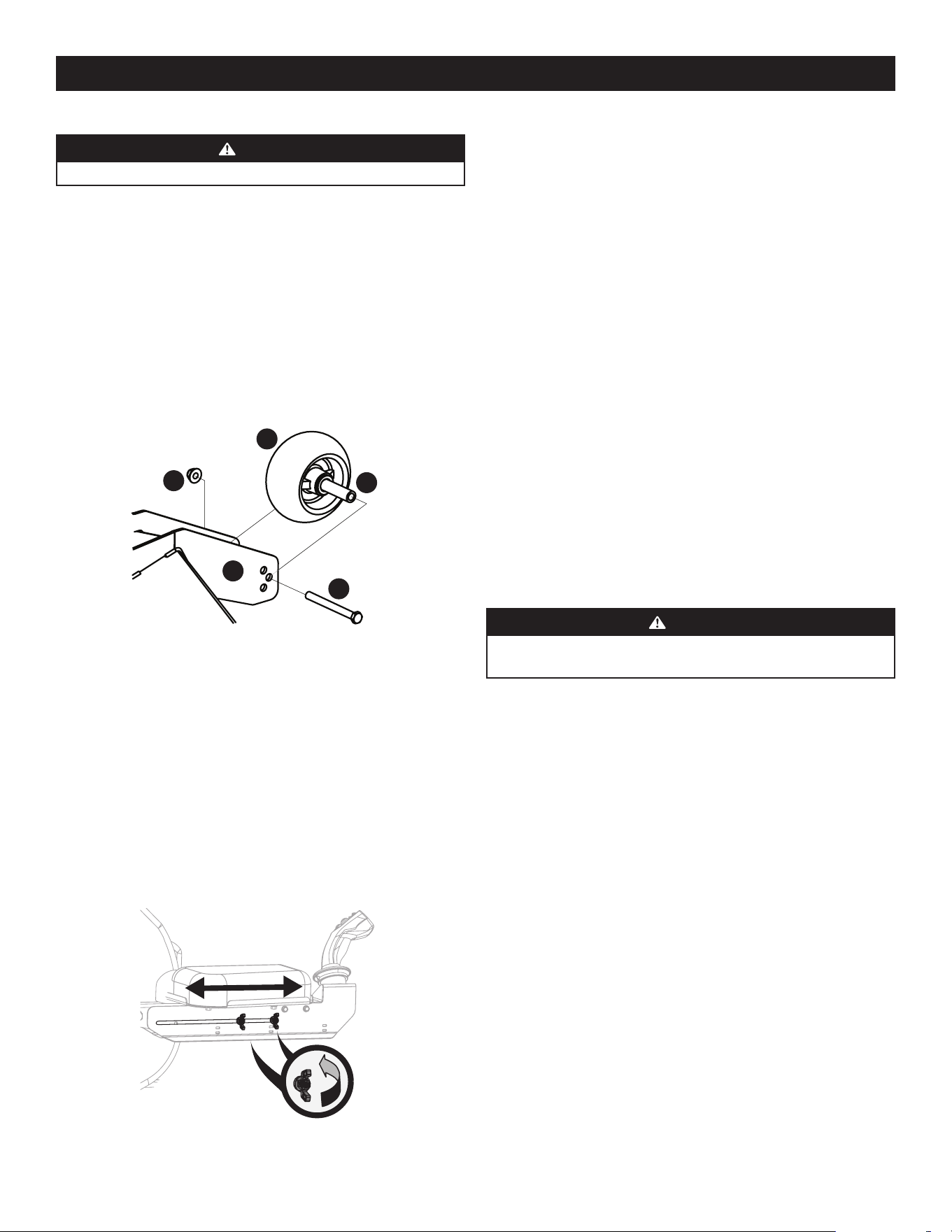
31
PRODUCT CARE
2. Slide upper portion of armrest forward or backward until positioned to
operator preference.
3. Retighten all four wing nuts by hand to secure armrest.
NOTE: Cable powering Operator Control Panel runs along underside of right
armrest. Do not pinch or kink cable while adjusting armrest.
SERVICE
Global Positioning Module (GPM)
Do not attempt to modify or repair the GPM. Please see an authorized service dealer
for any issues with the GPM.
Charging the Battery
Test and, if necessary, recharge the battery after the mower has been stored for a
period of time.
A voltmeter or load tester reading of 12.4 volts (DC) or lower across the battery
terminals indicates that the battery needs to be charged.
• An AGM battery charger should be used. Recommended charge rate
is 1.1A/14.8V.
• If your battery charger is automatic, charge the battery until the charger
indicates that charging is complete. If the charger is not automatic, charge for
no fewer than eight (8) hours.
Auxiliary Alternator
Please see an authorized service dealer for replacement of auxiliary alternator.
Jump Starting
WARNING
Failure to use this starting procedure can cause sparking, and the gases in
the battery to explode.
1. Connect the end of one cable to the disabled mower battery’s positive
terminal; then connect the other end of that cable to the booster battery’s
positive terminal.
2. Connect one end of the other cable to the booster battery’s negative terminal;
then connect the other end of that cable to the frame of the disabled mower, as
far from the battery as possible.
3. Start the disabled mower following the normal starting instructions previously
provided; then disconnect the jumper cables in the exact reverse order of
their connection.
4. Have the mower’s electrical system checked and repaired as soon as possible to
eliminate the need for jump starting.
Adjusting the Front Gauge Wheels
WARNING
Keep hands and feet away from the discharge opening of the cutting deck.
The front gauge wheels on the mower deck are an anti-scalp feature, and should not
ride on the ground. The front gauge wheels should be approximately 1/4-1/2” above
the ground when the deck is set in the desired height setting.
Using the deck lift handle, set the deck in the desired height setting, then check the
gauge wheel distance from the ground below. If necessary adjust the front gauge
wheels as follows:
1. Visually check the distance between the front gauge wheels and the ground.
If the gauge wheels are near or touching the ground, they should be raised. If
more than 1/2” above the ground, they should be lowered.
2. Remove the lock nut (a) securing one of the front gauge wheels (b) to the deck.
Remove the front gauge wheel (b), hex screw (c) and spacer (d). See Figure 40.
a
b
c
d
e
Figure 40
NOTE: There are a pair of front gauge wheels on the nose of the 60” deck.
3. Insert the hex screw (c) into one of the three index holes in the front gauge
wheel bracket (e) that will give the front gauge wheel (b) a 1/4-1/2” clearance
with the ground.
4. Note the index hole of the just-adjusted front gauge wheel (b), and adjust the
other front gauge wheel (b) into the respective index hole of the other front
gauge wheel bracket (e).
Adjusting the Operator Control Panel Armrest
Adjust the right armrest (Operator Control Panel side) as follows:
1. Loosen the four (4) wing nuts located on the underside of the right armrest by
turning counter-clockwise by hand. See Figure 41.
Figure 41
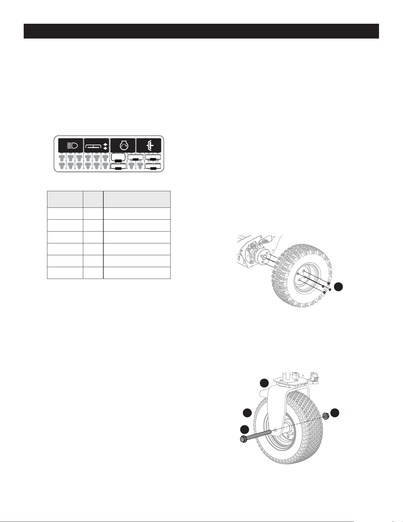
32
PRODUCT CARE
Servicing Electrical System
FUSE
Fuses can be found by lifting the operator’s seat. Most of the fuses are in the main
power distribution module (PDM) to the right of the battery (see Figure 42 for fuse
layout and Figure 43 for fuse assignments). These are standard mini type (ATM)
plug-in automotive fuses. Always use the same capacity fuse for replacement. Two
additional fuses, the Electronic Power Steering (EPS) and Alternator, are in single
MAXI fuse holders near the main PDM.
If you have a recurring problem with blown fuses, have the mower’s electrical system
checked by an authorized service dealer.
R4
R1 R2 R3 R4
F1
F2
F5
-10-
F4
-30-
B1
-15-
-25-
-10-
B1
F4 F1
F2F5
R1
R2 R3
R4
Figure 42
Reference Value Circuits
F1: Main Fuse 25A +12V System
F2: Lights 10A Lighting system (optional)*
F4: Start 30A Starter Solenoid
F5: GPM 10A Main GPM
EPS 60A Electric Power Steering
ALT 60A Alternator
*+12V system required to enable
Figure 43
Safety Interlock System & Switch Operation Checks
The following operational checks should be made daily:
PTO SWITCH
1. Sit in the operator’s seat. With the drive pedals in the neutral position and the
parking brake engaged, engage the PTO switch by pulling up on the knob and
try to start the engine. The engine should not start. If it does, the PTO switch
must be replaced. See your authorized service dealer.
2. If the engine does not start, disengage the PTO by pressing the knob down and
start the engine. Now engage the PTO and the blades should rotate.
3. If the blades do not turn, the PTO switch must be replaced, the seat switch
must be replaced or the electric PTO clutch must be repaired. See your
authorized service dealer.
PARKING BRAKE SWITCH
1. Sit in the operator’s seat. With the drive pedals in the neutral position and the
PTO disengaged, release the parking brake and try to start the engine. The
engine should not start.
2. If it does, the parking brake switch must be repositioned or replaced. See your
authorized service dealer. If the engine does not start, engage the parking
brake and start the engine.
SEAT SWITCH
1. With the drive pedals in the neutral position, the parking brake engaged and
the PTO disengaged, start the engine. Now release the parking brake and raise
up off the seat. Release the operator’s seat and the engine should stop. If the
engine does not stop, the seat switch must be replaced. See an authorized
service dealer.
2. With the drive pedals in the neutral position, the parking brake engaged and
the PTO disengaged, sit in the operator’s seat and start the engine. Engage the
PTO and the blades should start to rotate. Raise up slightly off the operator’s
seat and the blades should stop. If the blades do not stop when you dismount
from the operator’s seat, the seat switch must be replaced. See your authorized
service dealer.
ELECTRIC PTO CLUTCH
1. This clutch operates when the engine is running, the operator is in the
operator’s seat and the PTO is engaged. This electric clutch is normally a trouble
free device. If a problem develops and the blades do not turn, first check the
25 amp fuse, then investigate the wiring harness and the connections to the
seat switch, the PTO switch and the electric blade clutch. Then check the seat
switch, the PTO switch and finally the electric blade clutch. If the PTO clutch is
still not working properly, see an authorized service dealer.
Rear Tire Removal/Replacement
1. Remove the four lug nuts (a) to remove the tire. See Figure 44.
a
Figure 44
2. Reinstall the tires using the four lug nuts. See Figure 44. Torque the lug nuts (a)
to 65-70 ft-lbs.
Front Tire Removal/Replacement
1. Remove the hex screw (a) and flange lock nut (b) that secures the front wheel
(c) to the yoke assembly (d). See Figure 45.
a
bc
d
Figure 45
2. To re-install or replace the front tire, reverse Step 1. Tighten the hardware to
75-90 ft-lbs. See Figure 45.
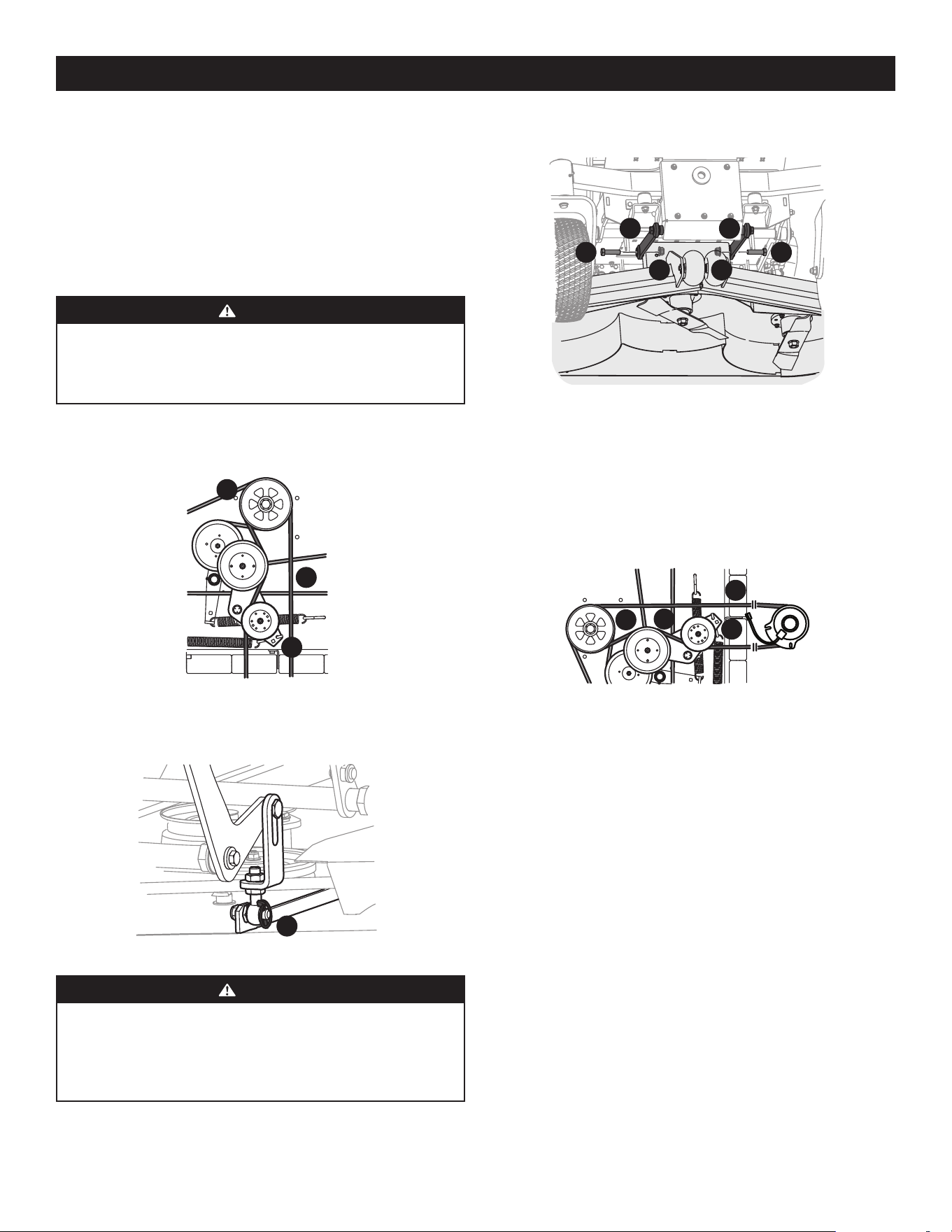
33
PRODUCT CARE
Speed Sensor (Rear Tires)
Please see an authorized service dealer for replacement or adjustment of
speed sensor.
Deck Removal
Remove the mower deck from the mower as follows:
1. Lower the deck to the ground. Capture the deck lift by placing the clevis pin
behind the lowest position.
2. Apply the parking brake. Remove ignition key and the spark plug cap.
WARNING
The muffler and any surrounding parts at the rear of the mower may be
extremely hot, and could cause serious burns. Use extreme caution when
near the muffler. Allow the muffler to fully cool before removing the belt
from the PTO pulley.
3. Using a 1/2” drive in the idler pulley bracket (a), turn the wrench towards
the right of the mower and slide the PTO belt (b) off the PTO pulley (c). See
Figure 46.
c
a
b
Figure 46
4. Remove the four lynch pins (a) that secure the deck to the deck lift assembly.
See Figure 47.
a
Figure 47
WARNING
The spring is under tension due to the weight of the deck. When removing
the lift linkage from the deck the tension of the springs will go from the
deck to the deck lift pedal. Failure to capture the deck lift pedal by placing
the clevis pin behind the lowest position while removing the lift linkage
from the deck will cause it to snap back and may result in personal injury.
5. Remove the hex screws (a) and flange lock nuts (b) securing the front deck
control rods (c) to the deck. See Figure 48.
a a
b b
c c
Figure 48
6. Turn front wheels as if to make a pivot turn.
7. Shift the deck toward the right side of the mower and remove.
8. To install reverse the process.
Replacing the PTO Belt
1. Remove the PTO belt (a) from the deck as instructed in the Deck Removal
section then remove it from around the PTO clutch. See Figure 49.
b
a
c
d
Figure 49
2. Route the PTO belt (a) as shown in Figure 49.
3. After routing the belt around the PTO pulley (b), use a 1/2” drive in the idler
pulley bracket (c) and turn towards the right of the mower to finish routing the
belt around the idler pulley (d). See Figure 49.
4. Reinstall the deck by reversing the previous steps.
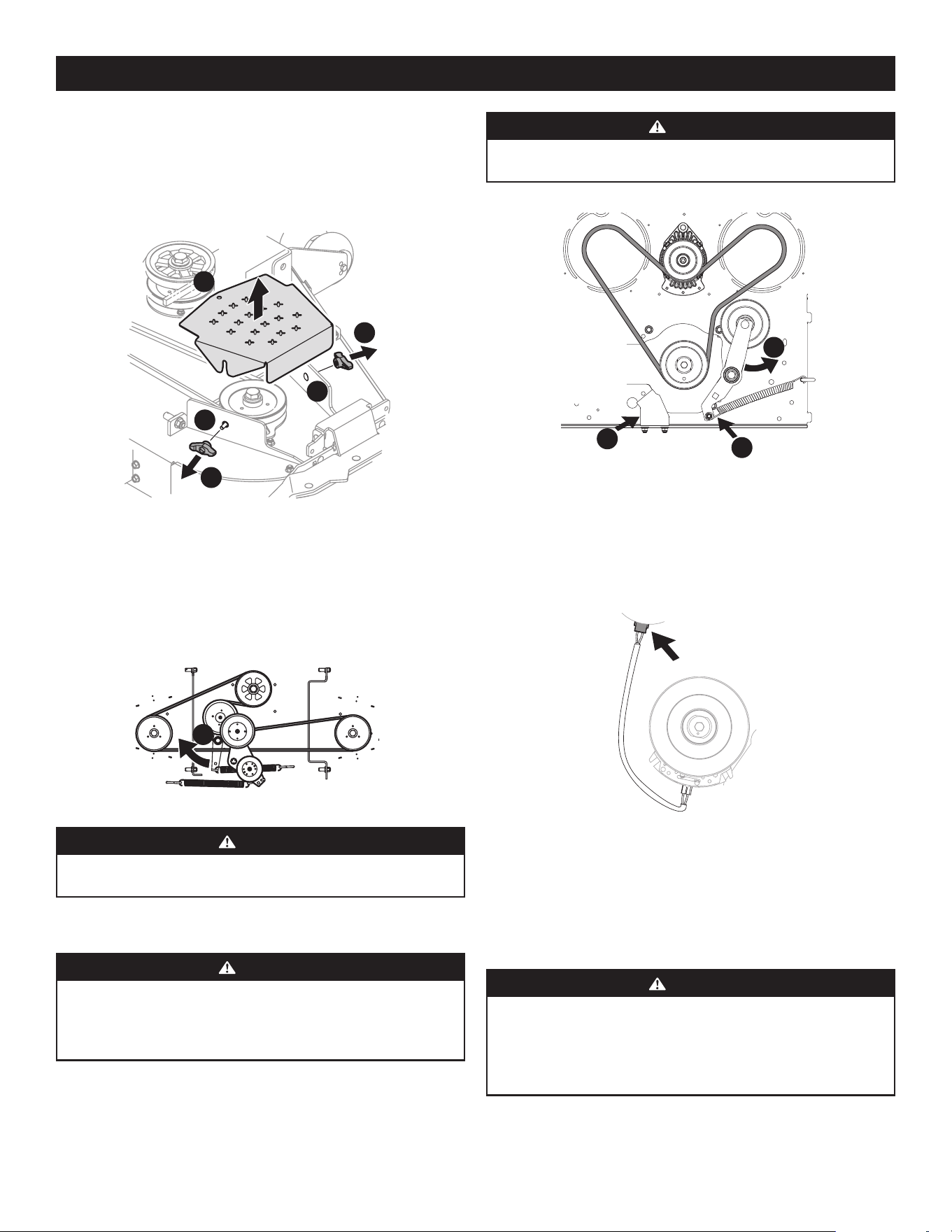
34
PRODUCT CARE
Replacing the Deck Belt
1. Set the parking brake. Remove ignition key and both spark plug caps.
2. Remove the PTO belt (refer to Deck Removal).
3. To remove the belt covers (a), remove the wing knobs (b) from the carriage
screws (c) securing it to the deck. See Figure 50.
a
b
b
c
c
Figure 50
4. The speed nut should hold the carriage screw (c) and tab bolt in place, if not
re-install as shown in Figure 50.
5. Using a 1/2” drive insert the end into the 1/2” square opening in the deck idler
assembly (a) and rotate the deck idler assembly (a) clockwise. See Figure 51.
While holding the deck idler assembly (a), loosen the deck belt from the pulley
and slide the belt away from the pulley.
a
Figure 51
WARNING
Avoid pinching injuries. Never place your fingers on the idler spring or
between the belt and a pulley while removing the belt.
6. Route the new belt as shown in Figure 51. Then reinstall the deck and PTO belt.
Replacing the Drive Belt
WARNING
Before performing any maintenance, disengage the PTO, engage the
parking brake lever, turn the ignition key to the OFF position, and remove
the key from the switch. Muffler and engine become hot and can cause a
burn. Allow the machine to cool at least 5 minutes before servicing.
1. Remove PTO belt from clutch only, refer to Deck Removal for releasing tension
on PTO belt.
2. Release tension off of idler by removing spring from idler arm. See (a) in
Figure 52.
WARNING
The spring is under tension due to the weight of the deck. Be careful when
removing, may cause personal injury. Wear gloves and safety glasses.
a
b
c
Hydro Transmissions Not Shown For Clarity
View Shown
from Under
Mower
Looking Up
Figure 52
3. Rotate idler arm out of the way of the PTO belt. See (b) in Figure 52.
4. Remove anti-rotation bracket from frame by loosening the two nuts securing it
to the deck. See (c) in Figure 52.
5. Unplug electrical connector from clutch housing. Allow to hang free for
reinstallation later in these instructions. See Figure 53.
Figure 53
6. Remove existing drive belt.
7. Route new belt up around clutch and engine idler pulley as shown in Figure 52.
8. Reinstall the electrical connector, anti-rotation bracket, idler arm and PTO belt
by reversing Steps 1-5.
Replacing the Blades
WARNING
Before performing any maintenance, disengage the PTO, engage the
parking brake lever, turn the ignition key to the OFF position, and remove
the key from the switch. Protect your hands by using heavy gloves when
handling the blades. When servicing the mower deck, be careful not to cut
yourself on the sharpened blades.
1. Remove the deck as instructed in the Deck Removal section.
2. For easier access, flip the deck over, then jack up the front of the deck about one
foot and block it in that position.
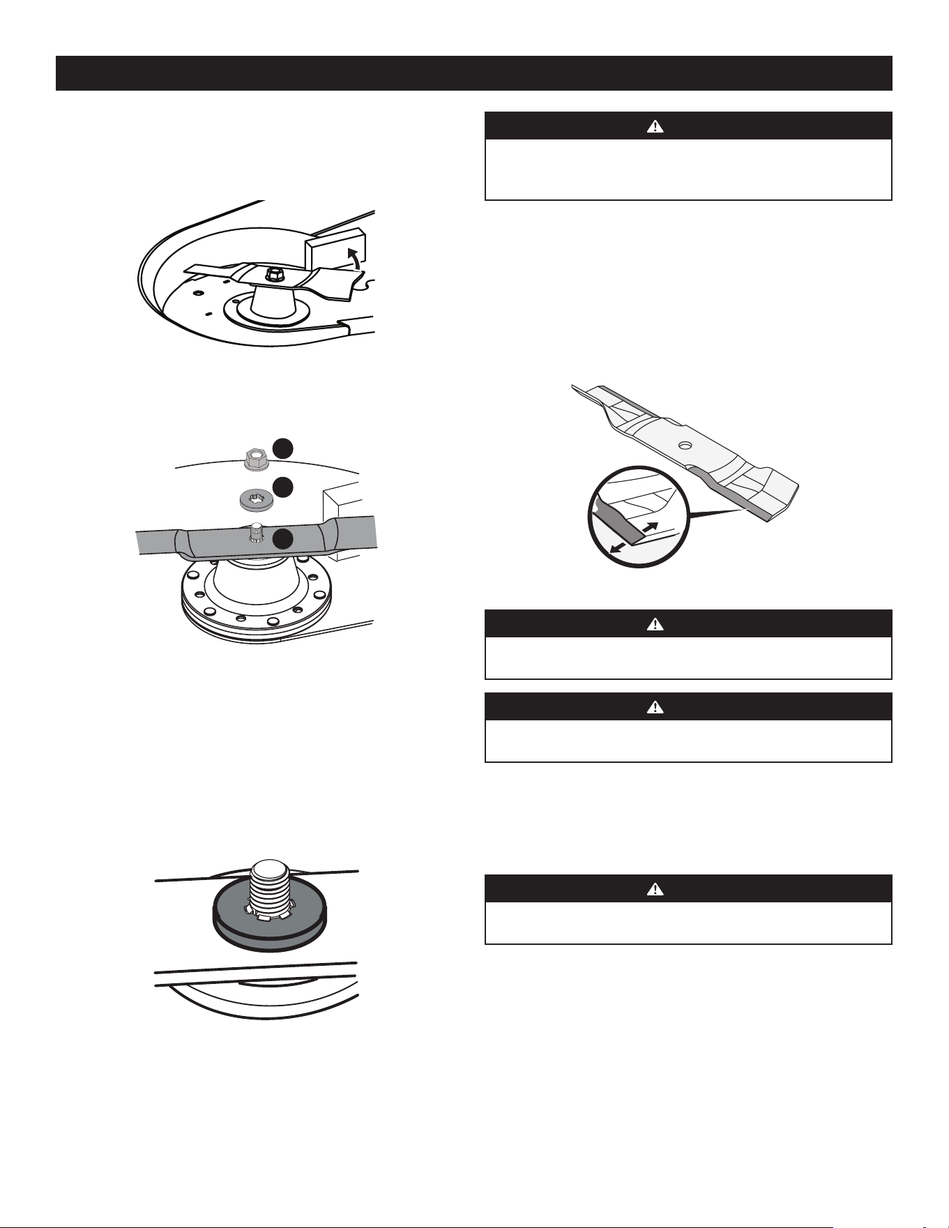
35
PRODUCT CARE
WARNING
Never mow with dull blades. Blades that are bent should be replaced. The
cutting blades are sharp and can cause severe injury. Wrap the cutting
surface of the blade with a rag and wear heavy gloves to avoid injury.
Sharpening the Blades
1. Set the parking brake.
2. Clean any debris from the blades. Keep blades sharp and free of build up at
all times.
3. To properly sharpen the cutting blades, remove equal amounts of metal from
both ends of the blades along the cutting edges, parallel to the trailing edge,
at a 25°-30° angle. Always grind each cutting blade edge equally to maintain
proper blade balance. See Figure 57.
Figure 57
WARNING
If a blade is bent or otherwise damaged, replace the blade with a new one.
Use only original equipment blades.
WARNING
A poorly balanced blade will cause excessive vibration, may damage the
machine, and/or result in personal injury.
4. Test the blade’s balance using a blade balancer. Grind metal from the heavy
side until it balances evenly.
NOTE: When replacing the blade, be sure to install the blade with the side of
the blade marked ‘‘Bottom’’ or “Grass Side” (or with a part number stamped in
it) facing the ground when the mower is in the operating position.
WARNING
Use a torque wrench to tighten the blade spindle hex flange nut to between
100 ft-lbs and 130 ft-lbs.
Changing the Spindle Assembly
1. Remove the deck as instructed in the Deck Removal section.
2. Jack up the front of the mowing deck about one foot and block it in
that position.
3. Remove the deck cover.
4. Remove the drive belts. See Replacing the Drive Belt.
5. Remove the blade. See Replacing the Blades.
To remove the blade:
1. Secure the blade from turning counter-clockwise during service by placing a
block of wood between the blade and the deck housing, see Figure 54, or wrap
a rag around one end of the blade and grasp the blade firmly.
Figure 54
2. Remove the flange lock nut (a) and flat washer (b) from the spindle shaft and
remove the blade (c). See Figure 55.
a
b
c
Figure 55
To replace or reinstall the blade:
1. Put the blade in place on the spindle shaft. Be sure to install the blade with
the side marked “Bottom”, “Grass Side” or with a part number stamped
facing the ground when the deck is reinstalled on the mower and in the
operating position.
2. Carefully place the flat washer on the spindle shaft. Be sure that the splines
at the base of the spindle shaft threads line up with the washer splines. See
Figure 56.
Figure 56
3. Secure the blade from turning clockwise when reinstalling the flange lock nut
(the opposite direction of blade removal).
4. Install the flange lock nut onto the spindle shaft over the blade and flat washer.
Torque to 100-130 ft-lbs (136-176 N-m).
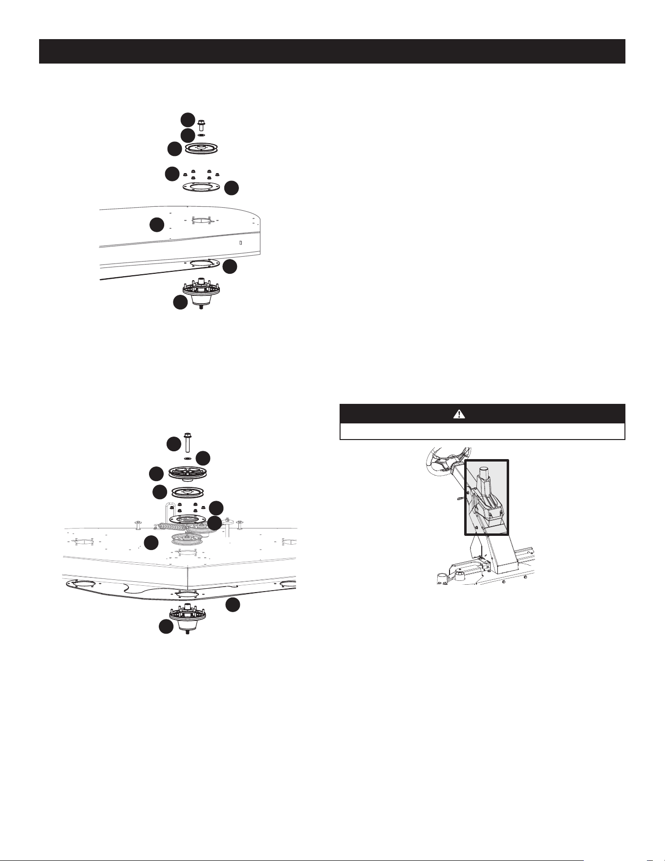
36
PRODUCT CARE
6. Remove the hex flange bolts (a) and flat washers (b) securing the left and right
spindle pulleys (c) to the spindle assembly (d). See Figure 58.
b
a
c
f
e
h
g
d
Figure 58
7. Remove the six (6) flange lock nuts (e) securing the left and right spindle
assemblies (d) and the support plates (f) to the deck shell (g). See Figure 58.
NOTE: The deck support plate (h) does not need to be removed unless all three
spindles are being replaced. See Figure 58.
8. Remove the hex flange bolt (a) and flat washer (b) securing the drive pulley (c)
and center spindle pulley (d) to the spindle assembly (e). See Figure 59.
a
b
c
d
f
h
e
i
g
Figure 59
9. Remove the six (6) flange lock nuts (f) securing the center spindle pulley
(d), spindle assembly (e) and the support plates (g) to the deck shell (h). See
Figure 59.
NOTE: The deck support plate (i) does not need to be removed unless all three
spindles are being replaced. See Figure 59.
10. Reverse the process to install the spindle assembly. When installing the new
spindle assembly be sure to install the hardware exactly as shown in Figure
58. Torque the hex flange bolts to 250 ft-lbs and the flange lock nuts to 21-
32 ft-lbs.
Changing the Transmission Drive Belt
Several components must be removed and special tools used in order to change
the mower’s transmission drive belt. See your authorized service dealer to have the
transmission drive belt replaced.
Mower Creeping
Creeping is the slight forward or backward movement of the mower when the
throttle is on and the speed control pedals are in the neutral position. If your mower
creeps, see your authorized service dealer.
SUREPATH AUTO STEER SYSTEM
NOTE: SurePath Auto Steer system functionality requires connectivity to software
and services. The first year of your subscription is included in the price of the product.
All following years will need to be renewed at the current subscription cost. For more
details, and to purchase a subscription, please visit cubcadet.com/surepath.
Maintenance
• Never wash the GPM. If necessary, wipe the GPM with a clean micro-fiber towel
only. Never cover the GPM antenna. Covering the GPM antenna, even with
certain kinds of stickers, will inhibit GPS signal which will disable autonomous
function. See Figure 60.
WARNING
Do not block GPM.
Figure 60
• Debris can accumulate anywhere on the mower, especially on horizontal
surfaces. Additional cleaning may be necessary when mowing in dry conditions
or when mulching.
• Fuel leaks/spills, oil leaks/spills and excess lubrication can also become
collection sites for debris. Immediate repair and cleaning up oil or fuel spills can
help reduce fire hazards.
• In addition to cleaning the mower before operating and storing, do not
attempt to mow unusually tall grass (10” or higher), dry grass (e.g., pasture) or
piles of dry leaves. Dry grass or leaves may contact the engine exhaust and/or
build up on the mower deck presenting a potential fire hazard.
Global Positioning Module (GPM)
Do not attempt to modify or repair the GPM. Please see an authorized service dealer
for any issues with the GPM.

37
PRODUCT CARE
TROUBLESHOOTING
WARNING
Before performing any type of maintenance/service, disengage all controls and stop the engine. Wait until all moving parts have come to a complete stop.
Disconnect the spark plug wire(s) and negative battery cable to prevent unintended starting. Always wear safety glasses during operation or while performing
any adjustments or repairs.
This section addresses minor service issues.
Problem Cause Remedy
Excessive vibration 1. Cutting blade loose or unbalanced.
2. Damaged or bent cutting blade.
1. Tighten blade and spindle.
2. Replace blade.
Uneven cut 1. Deck not properly leveled.
2. Cutting blade dull or damaged.
3. Uneven tire pressure.
1. Perform side-to-side deck adjustment.
2. Sharpen or replace cutting blade.
3. Check and correct tire pressure in all four tires.
Mower will not mulch grass 1. Engine speed too low.
2. Wet grass.
3. Excessively high grass.
4. Dull blade.
1. Place throttle in FAST (rabbit) position.
2. Do not mulch when grass is wet.
3. Mow once at a high cutting height, then mow again at
desired height or make a narrower cutting swath.
4. Sharpen or replace blade.
Engine fails to start 1. PTO/Blade engaged.
2. Blown fuse.
3. Parking brake not engaged.
1. Place blade engage lever in disengaged (OFF) position.
2. Replace fuse(s). Replace with same rating fuse,
if necessary.
3. Engage parking brake.
See Engine Operator’s Manual.

38
PRODUCT CARE
Problem Cause Remedy
SurePath Auto Steer System
NOTE: SurePath Auto Steer system issues
may be resolved by turning the mower off,
waiting 10 seconds and then turning the
mower back on.
1. Indicator/Warning Lights do not flash blue after key is
turned on.
1. Check fuses. Replace with same rating fuse, if necessary.
2. Indicator/Warning Lights do not go solid green. 2. Move away from trees and buildings. Ensure nothing is
blocking the GPM.
3. Mower is in an open area but Indicator/Warning Lights
stay flashing green with periodic red.
3. Check for strength of cellular signal.
4. Mower is in an open area but Indicator/Warning Lights
stay flashing green (no periodic red).
4. Verify SurePath Auto Steer subscription as follows:
• Make sure annual subscription has not expired.
• Check if mower has been moved out of the
state(s) where SurePath Auto Steer subscription
was activated.
• Contact an authorized service dealer if the above
items do not resolve.
5. Indicator/Warning Lights flash yellow when you press
a button.
5. Review the following:
• SurePath Auto Steer system is not ready. Wait for GPS
indicator to be solid green.
• Mower has not traveled minimum recommended
distance to allow setting of the mowing line. See
Setting the Mowing Line (SurePath Auto Steer Mode).
• Invalid reset of mowing line. See Clearing the
Mowing Line (SurePath Auto Steer Mode).
6. Indicator/Warning Lights flash yellow while in Auto
Steer Mode.
6. Mower speed too fast. Reduce speed.
7. GPS indicator is ON but SurePath Auto Steer Mode will
not engage.
7. Resume use in manual mode and contact an authorized
service dealer to review active faults.
8. Indicator/Warning Lights flash red while system is being
used in SurePath Auto Steer Mode.
8. Verify the following:
• If mower is under a tree or near a structure move to
an open area and verify nothing is blocking the GPM.
• Check for strength of cellular signal.
• Resume use in manual mode and contact an
authorized service dealer to review active faults.
9. Indicator/Warning Lights flash red. 9. Resume use in manual mode and contact an authorized
service dealer to review active faults.
10. SurePath Auto Steer Mode leaves uncut areas between
mowing passes.
10. Turn Cutting Width knob counter-clockwise to increase
mowing overlap.
11. SurePath Auto Steer Mode is overlapping too much
between mowing passes.
11. Turn Cutting Width knob clockwise to reduce
mowing overlap.
12. SurePath Auto Steer Mode needs to be disabled. 12. To disable the SurePath Auto Steer Mode:
• Remove GPM fuse (labeled F5:GPM in the fuse box
located under the operator’s seat) to disable SurePath
Auto Steer system.
• Contact an authorized service dealer.

39
REPLACEMENT PARTS AND ACCESSORIESREPLACEMENT PARTS AND ACCESSORIES
Replacement Parts
Part Number Description
954-04319 Deck Belt
954-05128
954-05129
PTO Belt (60” Deck)
PTO Belt (72” Deck)
754P07134 Drive Belt
942-04415
742-04415-ES
942-05179
Hi-Lift Blade, 21.0 (60” Deck)
Eversharp™ Hi-Lift Blade, 21.0 (60” Deck)
Hi-Lift Blade, 25.0 (72” Deck)
918-08473 Deck Spindle
634-05451 Deck Wheel
731-11926 Deck Skid Guard
951-15243 Gas Cap
946-05260 Throttle Control Cable
946-05341B Choke Control
925-06908 Ignition Key
946-05103A Park Brake Cable
931-05396C
931-05419
Chute Assembly (60” Decks)
Chute Assembly (72” Decks)
634-05192
634-05428B
Rear Wheel Assembly, 26 x 12-12
Front Wheel Assembly 16 x 6.5-8
02003749 Front Axle Wear Plates, 1.125 x 5.0
741-0941A Front Axle Ball Bearings, 1.0 x 52 x 15
Attachments and Accessories
Part Number Description
59A30060150 Triple Bagger
59A30062150 60” Blower Kit
59A30063150 60” Bagger Fan
19B70039100 60” Mulch Kit
59A30053150 72” Mulch Kit
490-241-0036 Rear Tire Chain Kit
59B30021150 12V Outlet Receptacle
59B30011150 Work Light Kit
59A30057150 Ultra Traction Tire, 26 x 12-12
59A30058150 Ultra Traction Tire, 24 x 12-12
490-850-0008 Oil Siphon
490-850-0005 Blade Removal Tool
490-325-0020 Tire Sealant
490-900-0045 Oil Filter Wrench
490-900-0062 Armortek Non-Stick Spray
490-000-0028 Carburetor & Choke Cleaner

CUB CADET LLC -- LIMITED WARRANTY
100016 Rev J (October 13, 2021)
The limited warranty set forth herein is given by Cub Cadet LLC with respect to a new Cub Cadet® product (hereinafter “Product”) purchased and used in the
United States and/or Canada to the Initial Purchaser (as defined herein). This limited warranty does not cover Emission Control Systems and is not a Federal
Emission Control Warranty Statement, as defined by U.S. federal law. Please refer to the Federal Emission Control Warranty Statement in the operator’s manual
for warranties covering Emission Control Systems.
Scope of the Limited Warranty
Cub Cadet LLC warrants that the Product (except with regard to the components and circumstances defined below as “Exclusions”) will be free from defects in
materials and workmanship during the Warranty Period, as defined below. For purposes of this limited warranty, the “Initial Purchaser” is the first person/company
to purchase this new Product from an authorized Cub Cadet dealer, distributor, and/or retailer of such products, including a party for whom said Product was
purchased as a gift. This limited warranty is non-transferrable. During the Warranty Period, Cub Cadet LLC will, at its option, either repair or replace any original
part that is covered by this limited warranty and is determined to be defective in workmanship or material. “Commercial Use” shall be defined as any commercial,
professional, agricultural, institutional, or income-producing use of the Product. See notes below as to Commercial Use Warranty.
Cub Cadet® Warranty Information
Handheld Product* Warranty Period
Chainsaws, Cultivators, Blowers, Brushcutters, Trimmers 3 Year
Wheeled Chore and Snow Product*
Chipper-Shredders, Chipper-Shredder Vacuums, Blowers, Log Splitters, Snow Blowers 3 Year
Tillers, String Trimmers, Lawn Edgers, Pressure Washers CC3224, CC3425 & CC4033 3 Year†
Pressure Washers 2 Year†
Battery Powered Product
60 Volt Max Product Series, CC30E, XT1 LT42E, ZT1 42E 3 Year†
60 Volt Max Product Series, CC30E, XT1 LT42E, ZT1 42E Batteries 4 Year†
Gas Powered Product
Ultima ZTX Series 4 Year/800 hour (whichever comes first)
Z-Force SX 4 Year/500 hour (whichever comes first)
Walk-Behinds, Wide-Area Walk-Behinds, CC30 Riders, XT1 & XT2 Enduro Series, RZT S/SX, Ultima ZT Series,
Z-Force S
3 Year†
23” Walk-Behinds, XT3 Enduro Series 4 Year†
Rotary Spreader 1 Year
Gas Blowers, PRO HW, PRO X-636 2 Year
PRO Z 500/700/900, PRO X-648/654/660, TANK LZ/SZ 3 Year
PRO Z 100 S 2 Year/NHL (No Hour Limit) or 4 Year/500 hour
(whichever comes first)
Utility Vehicle*
Challenger Series, Volunteer Series 1 Year
Additional Warranty Notes
Lead-Acid Batteries: Are covered by a one (1) year prorated limited warranty against defects in material and workmanship, with 100% replacement during
the first three (3) months, from the date of original purchase by the Initial Purchaser. After three (3) months, the battery replacement credit is based on the
months remaining in the twelve (12) month period, dating back to the date of original purchase by the Initial Purchaser. Any replacement battery will be
warranted only for the remainder of the original warranty period.
Frames: The frame, chassis, and front axle on all XT1, XT2 and XT3 products are covered for “Residential Use” by a five (5) year limited warranty. The frame on
all Ultima ZT and ZTX series products are covered for “Residential Use” by a seven (7) year Limited Lifetime Warranty.
Mowing Decks: 1) Cub Cadet LLC warrants the mowing decks under the warranty of the product it came with unless otherwise stated. 2) When so equipped,
the optional fabricated cutting deck shell (excluding wear parts, etc. thereon) shall be warranted against defects in material and workmanship for the lifetime
of the product, namely for as long as it is owned by its Initial Purchaser or the party for whom it was originally purchased as a gift, or seven (7) years from the
date of its initial sale to an Initial Purchaser, whichever comes first. 3) The deck shell, deck spindles, and deck steel pulleys (collectively the “Deck Assembly”)
on PRO Z 500 / 700 / 900 and PRO X-600 product only, shall also be warranted to be free from defects in material and workmanship for up to an additional
two (2) years (a total of five (5) years from date of purchase) or 1,750 cumulative hours of operation, whichever comes first. For purposes of clarity, no hour
limitation applies during the initial three (3) year period described above.
Snow Blowers: Three-Stage and Two-Stage (excluding 2X 24 models) - Auger gear boxes have a five (5) year limited warranty.
L and S Series: RZT L/LX, Z-Force L/LX/SZ, PRO Z 100 L, Z-Force Commercial (LZ/SZ), and Tank (L/S): Please refer to warranty included with Operator’s
Manual.
Attachments/Accessories: Please refer to warranty with Operator’s Manual.
*Limited Commercial Use Warranty: Handheld products – 90 days; Chipper-Shredder Vacuums, Blowers, Log Splitters, Snow Blowers – 1 year;
Utility Vehicle – 6 month.
† No Commercial Use Warranty: Tillers, String Trimmers, Lawn Edgers, Pressure Washers, Battery Powered Product, Walk Behind Mowers, 60 Volt Max
Product Series, CC30 Riders, Enduro Series, RZT S/SX, Ultima ZT Series, and Z-Force.
The limited warranty is non-transferrable

How to Get Service Under This Limited Warranty
In order to qualify for the limited warranty, as set forth herein, the repairs
made under this warranty must be performed by an authorized Cub Cadet
service provider. To locate a Cub Cadet service provider, contact your
authorized Cub Cadet dealer, distributor, or retailer, or contact Cub Cadet
LLC at P.O. Box 368023, Cleveland, Ohio 44136-0019, or call 1-877-282-8684,
or log on to our Website at www.cubcadet.com. For Canada, contact MTD
Products Limited, 97 Kent Ave, Kitchener, ON N2G 3R2, or call 1-800-668-1238,
or log on to our Website at www.cubcadet.ca. This limited product warranty is
provided by Cub Cadet LLC and is the only product warranty provided by Cub
Cadet LLC for the Product. A COPY OF YOUR SALES RECEIPT IS REQUIRED FOR
WARRANTY SERVICE.
What This Limited Warranty Does Not Cover
This limited warranty does not cover the following (the “Exclusions”):
1. Product purchased outside of the United States or Canada.
2. Emission Control Systems. These items are subject to a separate warranty
under the applicable Federal Emission Control Warranty Statement.
Please refer to the applicable Federal Emission Control Warranty
Statement for terms and conditions relating to Emission Control Systems.
3. Damage due to lack of maintenance and/or improper maintenance, as
described in the operator’s manual.
4. Normal wear and tear resulting from use of the Product.
5. Normal Wear Parts (as defined herein) are warranted to be free from
defects in material and workmanship for a period of thirty (30) days from
the date of original purchase by the Initial Purchaser for residential use,
and for 30 days or 100 hours (whichever occurs first) for Product used
commercially. Depending on Product, Normal Wear Parts include, but
are not limited to items such as: belts, blades, blade adapters, grass bags,
rider deck wheels, seats, shave plates, skid shoes, tines, filters, nozzles,
hoses, O-rings, spray guns, wands, tires, spark plugs, fuses, bump knobs,
outer spools, cutting line, inner belts, starter pulley, starter rope, drive
belts, saw chains, guide bars, and other consumable items.
6. Log splitter pumps, valves, and cylinders are covered for a period of one
(1) year.
7. Use of the product that is not consistent with the intended use thereof,
as described in the operating instructions, including, but not limited
to, abuse, misuse and/or neglect of the Product, or any use inconsistent
with and/or non-compliant with instructions contained in the Operator’s
Manual. This includes operation in sandy and/or corrosive environments.
8. Any Product that has been altered or modified in a manner not
consistent with the original design of the Product or in a manner not
approved by Cub Cadet LLC.
9. Paint repairs or replacements for defective paint (including materials and
application) are covered for a period of three (3) months.
10. Wheel rims (when so equipped) are covered for a period of three (3)
months for manufacturing defects.
This warranty does not cover, and Cub Cadet LLC disclaims any
responsibility for, matters including, but not limited to, the following:
1. Loss of time or loss of use of the Product.
2. Transportation costs and other expenses incurred in connection with the
transport of the Product to and from the authorized Cub Cadet service
provider.
3. Any loss or damage to other equipment or personal items.
4. Damages caused by improper maintenance or the use of other than the
specified fuel, oil, or lubricants, as approved in the operator’s manual.
5. Damage resulting from the installation or use of any accessory or part
not approved by Cub Cadet LLC for use with the Product.
Limitations
1. THERE ARE NO IMPLIED WARRANTIES, INCLUDING, BUT NOT LIMITED
TO, ANY IMPLIED WARRANTY OF MERCHANTABILITY OR FITNESS FOR
A PARTICULAR PURPOSE. NO WARRANTY SHALL APPLY AFTER THE
APPLICABLE WARRANTY PERIOD, AS SET FORTH ABOVE, AS TO THE
PARTS AS IDENTIFIED. NO OTHER EXPRESS WARRANTY OR GUARANTY,
WHETHER WRITTEN OR ORAL, EXCEPT AS MENTIONED ABOVE, GIVEN
BY ANY PERSON OR ENTITY, INCLUDING A DEALER OR RETAILER, WITH
RESPECT TO ANY, PRODUCT SHALL BIND CUB CADET LLC. DURING
THE WARRANTY PERIOD, THE EXCLUSIVE REMEDY IS REPAIR OR
REPLACEMENT OF THE DEFECTIVE PART, AS SET FORTH ABOVE. (SOME
STATES DO NOT ALLOW LIMITATIONS ON HOW LONG AN IMPLIED
WARRANTY LASTS, SO THE ABOVE LIMITATION MAY NOT APPLY TO YOU.)
2. THE PROVISIONS, AS SET FORTH HEREIN, PROVIDE THE SOLE AND
EXCLUSIVE REMEDY ARISING FROM THE SALE. CUB CADET LLC SHALL
NOT BE LIABLE FOR INCIDENTAL OR CONSEQUENTIAL LOSS OR DAMAGES
INCLUDING, WITHOUT LIMITATION, FOR TRANSPORTATION OR FOR
RELATED EXPENSES, OR FOR RENTAL EXPENSES TO TEMPORARILY
REPLACE A WARRANTED PRODUCT. (SOME STATES DO NOT ALLOW
THE EXCLUSION OR LIMITATION OF INCIDENTAL OR CONSEQUENTIAL
DAMAGES, SO THE ABOVE EXCLUSION OR LIMITATION MAY NOT APPLY
TO YOU.)
3. IN NO EVENT SHALL RECOVERY OF ANY KIND BE GREATER THAN THE
AMOUNT OF THE PURCHASE PRICE OF THE PRODUCT SOLD. ALTERATION
OF THE SAFETY FEATURES OF THE PRODUCT SHALL VOID THIS LIMITED
WARRANTY. YOU ASSUME THE RISK AND LIABILITY FOR LOSS, DAMAGE,
OR INJURY TO YOU AND YOUR PROPERTY, AND/OR TO OTHERS AND
THEIR PROPERTY, ARISING OUT OF THE USE OR MISUSE OR INABILITY TO
USE THE PRODUCT.
4. This limited warranty extends to the Initial Purchaser only and, except
as otherwise stated herein, the applicable Warranty Period will begin
on the original date of purchase of the Product. In the event that the
original date of purchase of the Product is indeterminable, then the
Warranty Period shall be established as beginning on the Product’s date
of manufacture, as determined by Cub Cadet LLC, and ending six (6)
months after the applicable Product Warranty Period, as defined above.
In no event shall a Product’s warranty extend beyond the applicable
Warranty Period.
How State Law Relates to This Warranty
This limited warranty gives you specific legal rights, and you may also have
other rights, which vary from state to state.
100016 Rev J (October 13, 2021)

Manual del OperadOr
Safe Operation Practices • Assembly & Set-Up • Controls & Operation • Product Care • Replacement Parts • Attachments & Accessories
Prácticas de operación seguras • Conguración • Operación • Cuidado del producto • Piezas de repuesto y accesorios • Garantía
Formulario nº 769-26692
(17 de enero de 2023)
Serie Conducción Automática SurePath Pro Z
Cortadora con radio de giro cero
NOTA: este Manual del Operador corresponde a varios modelos. Las características pueden variar según los modelos. No todas las características que se incluyen en este manual se
aplican a todos los modelos y el modelo que se ilustra aquí puede diferir del suyo.
ADVERTENCIA
Lea y cumpla todas las reglas e instrucciones de seguridad de este manual antes de intentar operar esta máquina.
Si no sigue estas instrucciones, se pueden provocar lesiones personales - GUARDE ESTAS INSTRUCCIONES.
ADVERTENCIA
PROPOSICIÓN 65 DE CALIFORNIA
El escape del motor de este producto, algunos de sus componentes y algunos componentes del vehículo contienen o liberan sustancias químicas que
el Estado de California considera que pueden producir cáncer, defectos de nacimiento u otros problemas reproductivos.
Los contactos, bornes y accesorios afines de las baterías contienen plomo y compuestos de plomo, sustancias químicas que según lo establecido
por el Estado de California causan cáncer y problemas reproductivos. Lávese las manos después de estar en contacto con estos componentes. www.
p65warnings.ca.gov
Registro de Información del Producto
Antes de configurar y hacer funcionar su equipo nuevo, por favor localice la placa de modelo
que viene en el equipo y registre la información en el espacio de la derecha. Para encontrar la
placa de modelo, eleve el asiento y mire en la parte inferior de la bandeja del asiento. Si tiene
que solicitar soporte técnico a través de nuestro sitio web o de un distribuidor de servicio local
autorizado, necesitará esta información.
Número de modelo
Número de serie
Inglés (English) ..................................................................................................................................................................................Página 1
Español ........................................................................................................................................................................................... Página 42

43
PRÁCTICAS DE OPERACIÓN SEGURAS
CAPACITACIÓN
1. Lea el manual del operador y el otro material de capacitación. Si los operadores
o los mecánicos no pueden leer en idioma inglés o español es responsabilidad
del propietario explicarles el presente material informativo.
2. Deberá familiarizarse con la operación segura de la máquina, los controles del
operador y los carteles de seguridad.
3. Todos los operadores y los mecánicos deberán capacitarse para operar o realizar
el mantenimiento del equipo. El propietario es responsable de capacitarlos.
4. Cumpla con todos los lineamientos federales, estatales y locales sobre el uso
por parte de niños menores de 18 años. En ningún caso debe permitir que niños
menores de 16 años utilicen esta máquina.
5. El operador es responsable de la operación segura de la máquina y de respetar
todas las advertencias, instrucciones y capacitación impartida.
FUNCIONAMIENTO GENERAL
1. Lea, entienda y cumpla todas las instrucciones incluidas en la máquina y en
el(los) manual(es) antes de intentar realizar el montaje de la unidad y utilizarla.
Guarde este manual en un lugar seguro para consultas futuras y periódicas por
parte de cada operador así como para solicitar repuestos.
2. Familiarícese con todos los controles y su correcto funcionamiento.
Sepa cómo detener la máquina y cómo desconectar las cuchillas y los
controles rápidamente.
3. No deje que nadie que no haya leído el manual opere o realice el
mantenimiento de esta máquina. No permita nunca que los niños menores de
16 años utilicen esta máquina.
4. No retire las protecciones, las etiquetas o los dispositivos de seguridad. Si una
protección, etiqueta o un dispositivo de seguridad está dañado o no funciona,
repárelo o reemplácelo antes de operar la máquina.
5. Para ayudar a evitar el contacto con las cuchillas o una lesión causada por algún
objeto que sea arrojado, mantenga a cualquier observador, ayudantes, niños y
mascotas alejados al menos 75 pies (23 metros) de la máquina mientras está en
funcionamiento. Pare la máquina si alguien ingresa al área.
6. Revise minuciosamente el área donde se va a usar el equipo. Saque todas las
piedras, palos, cables, huesos, juguetes y demás objetos extraños que puedan
ser recogidos y arrojados por la(s) cuchilla(s). Los objetos arrojados por la
máquina pueden producir lesiones graves.
7. Evalúe el terreno para determinar qué implementos y accesorios se necesitan
para realizar el trabajo de manera adecuada y segura. Utilice solamente
accesorios e implementos aprobados por el fabricante de la máquina.
8. Planifique el patrón de corte, para evitar que la descarga de materiales se dirija
hacia caminos, aceras, observadores, etc. Evite además descargar material
contra una pared u obstrucción, ya que esto podría hacer que el material
descargado rebotara contra el operador.
9. Siempre use ropa adecuada y equipos de protección personal (p.ej., anteojos
de seguridad, pantalones largos, guantes, protección auditiva, calzado de
seguridad, casco) cuando esté operando o manteniendo esta máquina. El
cabello largo, la vestimenta holgada o las alhajas pueden enredarse en las
piezas móviles. Respete todos los lineamientos federales, estatales y locales
relativos al uso de equipos de protección personal.
10. Se recomienda utilizar protección auditiva si se va a utilizar este producto
durante períodos prolongados.
11. Esté atento a la dirección de descarga de la cortadora y sus accesorios y no los
apunte a nadie. Nunca opere la cortadora de césped si no está bien colocada la
cubierta de descarga o el colector de césped completo.
12. No ponga las manos ni los pies cerca de las piezas rotatorias ni debajo de la
plataforma de corte. El contacto con la(s) cuchilla(s) puede amputar manos
y pies.
13. Una cubierta de descarga faltante o dañada puede provocar lesiones por
contacto con la cuchilla o por objetos arrojados.
14. Detenga la(s) cuchilla(s) cuando cruce caminos de gravilla, senderos o caminos
y cuando no esté cortando el césped.
15. Esté atento al tráfico cuando esté operando cerca de caminos o en cruces. Esta
máquina no está diseñada para ser usada en la vía pública.
16. No haga funcionar la máquina si se encuentra bajo los efectos del alcohol o
las drogas.
17. Úsela solamente con luz natural o con buena luz artificial.
18. Nunca lleve pasajeros.
19. Retroceda lentamente. Siempre mire hacia abajo y hacia atrás antes y mientras
retrocede para evitar accidentes.
20. Reduzca la velocidad antes de girar. Haga funcionar la máquina de manera
uniforme. Evite que funcione de manera errática y a excesiva velocidad. Tenga
en cuenta la dirección de desplazamiento para evitar accidentes.
21. Desenganche la(s) cuchilla(s), coloque el freno de mano, detenga el motor y
espere hasta que la(s) cuchilla(s) se detenga(n) por completo antes de retirar
el colector de recortes de césped, vaciar los recortes, desbloquear el canal de
descarga, retirar cualquier residuo o desecho, o realizar cualquier ajuste.
22. Nunca deje una máquina en funcionamiento sin vigilancia. Pare siempre sobre
suelo nivelado, apague la(s) cuchilla(s), ponga las palancas/pedales de control
de la velocidad de la transmisión en punto muerto, aplique el freno de mano,
apague el motor y saque la llave antes de salir de la posición del operador.
23. Tenga mucho cuidado al cargar o descargar la máquina en un remolque o
camión. No se debe conducir la máquina sobre rampas inestables, poco seguras
o inadecuadas porque podría volcarse y ocasionar graves lesiones personales.
24. No utilice el modo de Conducción Automática SurePath cuando esté cargando o
descargando la máquina de un remolque o camión.
ADVERTENCIA
Este símbolo indica instrucciones de seguridad importantes que, de no seguirse, podrían poner en peligro la seguridad personal y/o la propiedad
suya y de terceros. Lea y cumpla todas las instrucciones de este manual antes de intentar hacer funcionar esta tractora. Si no sigue estas
instrucciones, se pueden provocar lesiones personales. Cuando vea este símbolo. ¡Tenga en cuenta la ADVERTENCIA!
PELIGRO
Esta máquina está diseñada para ser utilizada respetando las prácticas de operación seguras contenidas en este manual. Al igual que con cualquier tipo de
equipo motorizado, un descuido o error por parte del operador puede producir lesiones graves. Esta máquina es capaz de amputar manos y pies y de arrojar
objetos. De no respetar las instrucciones de seguridad siguientes, se pueden ocasionar lesiones graves o la muerte.

44
PRÁCTICAS DE OPERACIÓN SEGURAS
25. Revise el espacio libre por encima de la cabeza antes de conducir bajo ramas
bajas de árboles, cables, cerramientos de puertas, etc. contra los cuales el
operador y/o la ROPS podrían golpearse, lo que podría resultar en lesiones
graves y/o el vuelco de la máquina.
26. El silenciador y el motor se recalientan y pueden producir quemaduras. No
los toque.
27. Desenganche las cuchillas, coloque el freno de mano en la posición ‘on’ y
asegúrese de que las palancas/pedales de control de la velocidad estén en la
posición de punto muerto antes de intentar encender el motor. Solo encienda el
motor desde la posición del operador.
28. No intente cortar césped demasiado crecido, seco (como un pastizal) ni pilas de
hojas secas. El césped o las hojas secas pueden entrar en contacto con el escape
del motor y/o acumularse en la plataforma de corte presentando un potencial
peligro de incendio.
29. No detenga ni estacione la máquina sobre hojas, pasto o desechos secos, ni
sobre otros materiales combustibles.
30. Nunca intente operar la máquina sin la plataforma de corte adosada; la
máquina podría volcarse.
31. Mantenga la máquina y especialmente el sistema de escape del motor y los
componentes hidráulicos limpios y libres de grasa, pasto y hojas para reducir la
posibilidad de sobrecalentamiento e incendios.
32. Deje que la máquina se enfríe por lo menos 5 minutos antes de guardarla.
33. Utilice solamente accesorios e implementos aprobados para esta máquina por
su fabricante. Lea, comprenda y siga todas las instrucciones incluidas con el
accesorio o complemento aprobado.
34. Las estadísticas indican que los operadores de 65 años y más se ven
involucrados en un alto porcentaje de lesiones relacionadas con las cortadoras
de césped. Los operadores deben evaluar su capacidad para operar esta
máquina de manera suficientemente segura para protegerse a sí mismos y a
otros de lesiones graves.
35. No encienda ni opere la máquina si hay fugas de combustible o aceite; repárelas
de inmediato.
36. Cuando busque pérdidas de aceite, nunca pase su mano sobre mangueras
hidráulicas, líneas o accesorios. Nunca aprieta o ajuste las mangueras
hidráulicas, líneas o accesorios mientras el sistema esté bajo presión. Si el aceite
de alta presión penetra la piel, busque atención médica de inmediata pues de
lo contrario podrían producirse gangrenas y lesiones permanentes. No revise
fugas hidráulicas con las manos; use papel o cartón. Use guantes y anteojos de
seguridad cuando revise fugas.
37. No operar máquinas que se hayan dañado o no hayan recibido el
mantenimiento adecuado. Si la máquina estuviera dañada, haga que
la reparen.
38. Cuando se desplace hacia adelante con esta máquina, no deje que las
palancas/pedales de control de velocidad vuelvan a la posición neutral por
sí solos. Siempre opere las palancas/pedales de forma pareja y evite realizar
movimientos bruscos con los mismos al arrancar o detenerse.
39. Si se presentan situaciones que no están previstas en este manual, sea
cuidadoso y use el sentido común. Póngase en contacto con su representante
de atención al cliente para obtener ayuda.
OPERACIÓN EN PENDIENTES
Las pendientes son un factor importante en los accidentes ocasionados por pérdida
de control y vuelcos que pueden causar lesiones graves o la muerte. Todas las
pendientes requieren precaución extra. Si no puede retroceder por la pendiente o si
no se siente seguro, no realice ningún corte ni se desplace sobre ella.
Para su seguridad, use el indicador de pendientes que se incluye como parte de este
manual para medir la pendiente antes de operar la máquina en una zona inclinada.
Si la pendiente es de más de 20° (35%), como se muestra en el indicador, no haga
funcionar esta máquina en ese sector o podría causar lesiones graves.
Sí:
1. Corte de forma transversal a la pendiente, no hacia arriba ni hacia abajo. Tenga
sumo cuidado al cambiar de dirección en una pendiente.
2. Esté atento a los hoyos, surcos, baches, rocas, u otros objetos ocultos. El
terreno desnivelado puede hacer volcar la máquina. El césped alto puede
ocultar obstáculos.
3. Conduzca a baja velocidad. Elija una velocidad lo suficientemente baja, de
modo que no tenga que detenerse mientras está en la pendiente. Evite
arrancar o detenerse en una pendiente. Si los neumáticos no pueden mantener
la tracción, desenganche las cuchillas y baje lentamente y con cuidado por
la pendiente.
4. Todos los movimientos en las pendientes deben ser lentos y graduales. No
realice cambios bruscos de velocidad o dirección. La aceleración repentina
podría hacer que el frente de la máquina se levante y vuelque rápidamente
hacia atrás, lo que podría producir lesiones graves o la muerte.
5. Siga las recomendaciones del fabricante sobre los pesos o contrapesos de las
ruedas para mejorar la estabilidad.
6. Tenga mucho cuidado con los colectores de césped y otros accesorios. Pueden
modificar la estabilidad de la máquina.
No:
1. No gire en pendiente a menos que sea necesario; si lo hace, gire lentamente
cuesta arriba y tenga sumo cuidado al hacerlo.
2. No corte el césped cerca de barrancos, zanjas o terraplenes. La máquina
puede volcarse repentinamente si una de las ruedas está sobre el borde de un
acantilado o zanja o si se desmorona un borde.
3. No opere en pendientes o cerca de la orilla de un lago, laguna, río o arroyo
donde la máquina podría deslizarse, volcar o dar un tumbo y caer al agua.
4. No intente estabilizar la máquina poniendo el pie en el suelo.
5. Tenga mucho cuidado cuando utilice el cortadora de césped con el colector de
césped y otros accesorios. Pueden comprometer la estabilidad del cortadora de
césped. No utilice el colector de césped en pendientes superiores a 10° (17%).
6. No corte el césped húmedo. La reducción de la tracción puede causar derrapes
y/o pérdidas del control.
7. No arrastre cargas pesadas detrás de los accesorios (p. ej.: volquete cargado,
rodillo de césped, etc.) en pendientes de más de 5° (9%). Cuando se esté
deslizando cuesta abajo, el peso extra tiende a empujar la máquina y podría
hacer perder tracción y control (p.ej., la máquina podría acelerarse, el poder
de frenado y dirección se reducen, el accesorio podría plegarse y hacer volcar
la máquina).

45
PRÁCTICAS DE OPERACIÓN SEGURAS
INDICADOR DE PENDIENTE (CUBIERTA POSTERIOR)
ADVERTENCIA
Las pendientes son un factor importante en los accidentes ocasionados por
derrapes y caídas y pueden producir lesiones graves. Todas las pendientes
requieren precaución extra. Si no se siente seguro en una pendiente, no
corte el césped. No corte el césped en pendientes de más de 20° (35%).
Siempre corte el césped de forma transversal a la pendiente, nunca hacia
arriba y hacia abajo.
PARA DETERMINAR SI UNA PENDIENTE ES DEMASIADO EMPINADA Y EVITAR RIESGOS,
USE EL INDICADOR DE PENDIENTE QUE APARECE EN LA CUBIERTA POSTERIOR COMO
SE MUESTRA.
Para comprobar la pendiente, proceda de la siguiente manera:
1. Abra el manual por la contraportada y dóblelo por la línea de puntos.
2. Ubique un objeto vertical que esté sobre la pendiente o detrás de la misma (p.
ej., un poste, un edificio, un cerco, un árbol, etc.).
3. Alinee cualquiera de los lados del indicador de pendiente con el objeto.
4. Ajuste el indicador hacia arriba o abajo hasta que la esquina izquierda toque
la pendiente.
5. Si hay una separación por debajo del indicador, significa que la pendiente es
demasiado empinada para una operación segura.
NIÑOS
1. Se pueden producir accidentes trágicos si el operador no está alerta de la
presencia de niños. Por lo general, los niños se sienten atraídos por la máquina
y su actividad. Los niños no son conscientes de los peligros. Nunca asuma que
los niños permanecerán donde los vio por última vez.
a. Mantenga a los niños fuera del área de trabajo y bajo estricta vigilancia
de un adulto responsable además del propio operador.
b. Esté alerta y apague la máquina si un niño ingresa al área.
c. Mire siempre hacia atrás y abajo para ver que no haya niños pequeños.
Conduzca a baja velocidad.
d. Nunca transporte niños, ni siquiera con las cuchillas desactivadas. Podrían
caerse y resultar gravemente heridos o interferir con la operación segura
de la máquina.
e. Tenga mucho cuidado al aproximarse a esquinas ciegas, puertas,
arbustos, árboles u otros objetos que puedan obstaculizarle la vista de un
niño que pudiese correr al encuentro de la máquina.
f. Para evitar accidentes al estar retrocediendo, desenganche las cuchillas
antes de cambiar la dirección a marcha atrás.
g. Mantenga a los niños alejados de los motores calientes o
en funcionamiento. Pueden sufrir quemaduras al tocar un
silenciador caliente.
h. Retire la llave cuando la máquina quede sin vigilancia para evitar el
funcionamiento no autorizado.
2. Cumpla con todos los lineamientos federales, estatales y locales sobre el
uso por parte de niños menores de 18 años. No permita nunca que los niños
menores de 16 años utilicen esta máquina. Los niños de 16 años en adelante
deben leer y entender las instrucciones y las normas de seguridad contenidas
en este manual y sobre la máquina, y deben ser entrenados y supervisados por
un adulto.
REMOLQUE
1. No remolque cargas pesadas detrás de los accesorios (p. ej.: volquete cargado,
rodillo de césped, etc.) en pendientes de más de 5° (9%).
2. Remolque únicamente utilizando una máquina que cuente con un dispositivo
de enganche diseñado para tal fin. No acople equipo remolcado excepto en el
punto de enganche.
3. Siga las recomendaciones del fabricante sobre los límites de pesos de los
equipos remolcados y el remolque en pendiente.
4. Nunca permita que los niños y otras personas se suban a equipos remolcados.
5. En las pendientes, el peso del equipo remolcado puede causar pérdida de
tracción y pérdida de control.
6. Desplácese lentamente y deje distancia adicional para detenerse.
7. Realice giros amplios para el acodillamiento.
TRANSPORTE DE MÁQUINAS
1. Esta máquina no está diseñada para ser usada en la vía pública. Las máquinas
para uso en la vía pública deben cumplir con las ordenanzas locales y estatales,
SAE J137, y ANSI/ASABE S279 (requisitos de iluminación y marcación).
2. Tenga mucho cuidado al cargar o descargar máquinas en remolques
o camiones.
3. No utilice el modo de Conducción Automática SurePath cuando esté cargando o
descargando la máquina de un remolque o camión.
4. Si se utilizan rampas, deberán tener el ancho máximo, ser estables, tener una
capacidad nominal adecuada y estar aseguradas al remolque o camión. El
ángulo de la rampa no deberá exceder los 20° (35%) y el remolque o el camión
deben estar estacionados sobre terreno nivelado.
5. Las máquinas se deben sujetar a los remolques y camiones con correas,
cadenas, cables, sogas o algún otro medio considerado adecuado para tal fin.
La parte delantera y trasera de las máquinas deberán sujetarse al camión o
remolque en los sentidos tanto vertical como lateral.
SISTEMA DE PROTECCIÓN DEL OPERADOR (OPS)
1. Esta máquina viene equipada con un Sistema de Protección del Operador (OPS),
que incluye:
a. Una Estructura de Protección Antivuelco (ROPS) de configuración fija
o plegable.
b. Conjunto de correa de asiento con función retráctil.
2. Las ROPS son estructuras diseñadas para proporcionar al operador un espacio
resistente a los accidentes/choques cuando esté correctamente sentado y con
el cinturón puesto dentro del área designada de la máquina en caso de que la
máquina vuelque. Las ROPS plegables deben usarse en sus configuraciones
totalmente vertical y trabada salvo en circunstancias en las cuales se tuviesen
que plegar momentáneamente para evitar contacto con objetos como ramas
de árboles, sogas para colgar ropa, retenidas de alambre, postes de servicios
públicos, edificios, etc. En todo otro momento y condiciones, la ROPS debe estar
en sus configuraciones totalmente vertical y trabada.
PELIGRO
La ROPS dañada debe reemplazarse previo a su uso por el operador.

46
PRÁCTICAS DE OPERACIÓN SEGURAS
3. Los cinturones de los asientos deben usarse y deben envolver correctamente la
cintura del operador en todo momento, salvo cuando la ROPS:
a. No esté correctamente instalada y/o no esté correctamente asegurada a
la máquina.
b. Esté dañada a punto tal de quedar comprometida su
integridad estructural.
c. No esté en su posición totalmente vertical y trabada.
4. Los cinturones de los asientos se fijan a la parte movible del asiento cuando se
utilizan asientos con suspensión, y por lo tanto la base del asiento debe estar
asegurada a su pivote y el pivote asegurado al bastidor de la máquina. Los
cinturones de los asientos se fijan al asiento o al bastidor de la máquina cuando
se proporcionan asientos sin suspensión (estándar); sin embargo, si a un asiento
se agrega un kit de suspensión, el cinturón debe adosarse a la parte movible del
asiento o mecanismo de suspensión, la base del asiento debe estar asegurada a
su pivote y el pivote asegurado al bastidor de la máquina.
PELIGRO
Si la ROPS está plegada o falta, los cinturones del asiento no deben estar
fijados. Los conjuntos de cinturones de asiento desgastados o dañados
deben reemplazare antes de su uso por el operador.
5. Una protección de cepillo o toldo podrían desviar las ramas de árboles, sogas
para colgar ropa y otros obstáculos que de otro modo podrían entrar en
contacto con la ROPS. El contacto con la ROPS, la protección de cepillo y/o los
toldos por parte de objetos como ramas de árboles, sogas para colgar ropa,
retenidas de alambre y edificios, podría generar condiciones peligrosas en las
que la máquina podría volcar. Un toldo podría proteger al operador de estar
expuesto a condiciones del tiempo (luz solar, lluvia, etc.).
6. La ROPS y el cinturón del asiento son partes integrales de esta máquina y no
deberían ser alterados, modificados ni quitados.
7. Inspeccione la ROPS y el cinturón del asiento de forma regular para detectar
daños y su funcionamiento incorrecto. Reemplace todos los componentes que
están dañados o que no funcionan adecuadamente por repuestos autorizados.
8. La ROPS se extiende hacia arriba y detrás de la posición del operador; por
lo tanto el operador debe estar atento a un potencial contacto de la ROPS
con cosas como árboles, edificios, puertas, sogas para colgar ropa, cables de
servicios públicos, etc., que podrían hacer volcar la máquina. Tenga cuidado
en (o evite) áreas donde la ROPS pudiese entrar en contacto con estructuras,
árboles, etc.
9. Inspeccione la ROPS y el cinturón del asiento de forma regular para detectar
daños y su funcionamiento incorrecto. Reemplace todos los componentes que
están dañados o que no funcionan adecuadamente por repuestos autorizados.
10. El no usar correctamente el cinturón del asiento podría provocar lesiones graves
o incluso la muerte en caso de un vuelco accidental. Para que la ROPS sea
efectiva, el cinturón del asiento debe estar correctamente sujetado alrededor
del operador en todo momento cuando el operador esté en la máquina.
El contacto con la ROPS durante un vuelco podría causar lesiones graves o
la muerte.
11. La ROPS no evita que la máquina vuelque.
12. No suponga que la ROPS lo protegerá en caso de un vuelco. Aún así pueden
producirse lesiones.
DISPOSITIVOS Y SISTEMAS HIDRÁULICOS
El fluido hidráulico que escapa a presión puede tener fuerza suficiente para penetrar
la piel y causar lesiones graves. Si penetra algún fluido extraño en la piel o los ojos,
busque atención médica de inmediato pues de lo contrario podrían producirse
gangrenas o lesiones permanentes.
ADVERTENCIA
Mantenga el cuerpo y las manos alejados de orificios de pasadores o picos
que podrían expulsar líquido a alta presión. Utilice papel o cartón, no las
manos, para buscar fugas. Use guantes y anteojos de seguridad.
Libere de forma segura toda la presión en el sistema antes de realizar cualquier
trabajo en el sistema y asegúrese de que:
• El interruptor de encendido esté APAGADO.
• Se haya retirado la llave.
• Se hayan quitado los cables de la bujía.
• Se hayan quitado todas las conexiones al borne negativo de la batería.
• Se haya colocado el freno de mano.
• Se hayan abierto todas las válvulas de derivación, si se incluyen.
• Se hayan activado los controles hidráulicos para liberar presión en bombas,
cilindros, etc. Si hay posiciones de “flotación” disponibles, se las debe usar.
Una vez completadas las operaciones anteriores, debería ser seguro comenzar a
desconectar las líneas o los componentes. Siempre resulta una buena idea cubrir la
conexión con un protector de tela y luego aflojarla suavemente.
ADVERTENCIA
Antes de aplicar presión al sistema, verifique que todas las conexiones
de fluido hidráulico estén apretadas y que todas las mangueras y líneas
hidráulicas estén en buen estado.
MODO DE CONDUCCIÓN AUTOMÁTICA SUREPATH
1. Para evitar lesiones personales tanto suyas como de otras personas, siempre
sea precavido y esté atento a sus alrededores cuando esté usando el modo de
Conducción Automática SurePath. Detenga la máquina de inmediato si alguien
entra en la zona.
2. El sistema de Conducción Automática SurePath no detecta objetos ni
obstrucciones que puedan estar en el camino de la plataforma de corte o de
la máquina. Siempre opere la máquina con cuidado y atención. Detenga la
máquina de inmediato o condúzcala manualmente alrededor de obstáculos
antes de reanudar el modo de Conducción Automática SurePath.
3. La máquina está equipada con una Estructura de Protección Antivuelco (ROPS).
El modo de Conducción Automática SurePath no detecta objetos altos como
árboles, edificios, puertas, sogas para colgar ropa, cables de servicios públicos,
etc. Esté atento a estos objetos que podrían ser contactados por la ROPS y hacer
que la máquina vuelque.
4. Usted debe estar en control total de la máquina cuando esté activado el
sistema de Conducción Automática SurePath. Usted tiene la responsabilidad
de controlar la máquina, supervisar el sistema e intervenir, cuando sea
necesario. La omisión de hacerlo podría dar lugar a pérdida del control, lesiones
personales, o muerte.

47
PRÁCTICAS DE OPERACIÓN SEGURAS
5. El modo de Conducción Automática SurePath no es un sistema que evita
accidentes. El modo de Conducción Automática SurePath no hará desacelerar
o detener el vehículo. Siempre preste mucha atención cuando esté utilizando
el sistema. No es un sustituto de la atención del operador al usar la máquina.
En cualquier momento el modo de Conducción Automática SurePath puede
desactivarse tomando el volante y girándolo levemente hacia la derecha o
izquierda, o manteniendo presionado el botón Establecer Línea/Activar Auto.
6. El modo de Conducción Automática SurePath no detecta pendientes
pronunciadas, precipicios, lagunas ni lagos. Permanezca a una distancia de
al menos 10 pies (3 metros) de cualquier precipicio, laguna o lago. No haga
funcionar la máquina en pendientes superiores a 20° (35%).
7. El Módulo de Posicionamiento Global (GPM) de SurePath monitoreará
continuamente que el sistema de Conducción Automático SurePath esté
preparado para la tarea. Las luces indicadoras/de advertencia que están en
la parte posterior del GPM (sobre el Módulo de Luces) indicarán al operador
el estado del sistema mientras está en uso. El operador debe monitorear las
luces y estar preparado para retomar el control de la máquina. Si las luces
indicadoras/de advertencia parpadean en rojo, coloque las manos sobre el
volante y esté preparado para conducir o detener la máquina.
8. El GPM del sistema de Conducción Automática SurePath tiene que estar limpio
y libre de objetos extraños u obstrucciones que podrían afectar la capacidad de
la antena del GPS para recibir la señal del satélite.
9. Para evitar una exposición a RF por sobre los límites establecidos en la Parte 15,
Subparte A del FCC, permanezca al menos a 20 cm (8 pulgadas) del GPM cuando
la llave esté en posición ON.
10. El GPM podría perder la señal de satélite del GPS o conexión del celular en
cualquier momento debido a la presencia de copas de árboles grandes y
cerradas, edificios grandes, malas condiciones climáticas, interferencia
eléctrica, zonas muertas u otros obstáculos. El sistema de monitoreo está
diseñado para ser un asistente de la tarea de corte y no libera al operador de la
responsabilidad de operar la máquina en condiciones seguras y con el debido
cuidado. La omisión de observar el sistema de monitoreo podría dar lugar
a pérdida del control, daños materiales, lesiones personales, o la muerte. El
sistema de monitoreo no está concebido para ser un dispositivo de seguridad.
11. No intente girar a alta velocidad cuando esté usando el modo de Conducción
Automática SurePath. El sistema hará giros menos abruptos y más precisos a
velocidades más bajas.
12. No use el modo de Conducción Automática SurePath cuando esté remolcando
un complemento o remolque. La omisión de seguir esta instrucción podría
acodillar el equipo remolcado provocando la pérdida de control, daños
materiales, lesiones personales o la muerte.
13. El restablecimiento del sistema de Conducción Automática SurePath debe
realizarse mientras la cortadora de césped está detenida, y la PTO está en
la posición apagada. Si mantiene presionado el disparador por menos de 3
segundos, la línea no se restablecerá y la cortadora podría volver al modo
automático si las líneas pre-establecidas siguen guardadas. Se pueden producir
daños a la cortadora o lesiones personales.
14. El sistema de Conducción Automática SurePath no está concebido para usarlo
en desplazamientos marcha atrás.
15. Si el sistema de Conducción Automática SurePath sufre algún desperfecto, deje
de usar la máquina o desactive el sistema y hágalo reparar por un distribuidor
de servicio autorizado lo antes posible.
SERVICIO
Manipulación segura de combustible
Para evitar lesiones personales y daños materiales tenga mucho cuidado al
manipular el combustible. El combustible es sumamente inflamable y sus vapores
son explosivos. Si se derrama combustible encima o sobre la ropa se puede lesionar
gravemente ya que se podría prender fuego. Lávese la piel y cámbiese de ropa
de inmediato.
• Utilice sólo recipientes autorizados.
• Nunca llene los recipientes en el interior de un vehículo, camión o caja
de remolque cuando tenga un recubrimiento plástico o esté alfombrado.
Ubique siempre los recipientes en el piso, lejos del vehículo antes de
cargarles combustible.
• Cuando sea factible, retire la cortadora de césped del camión o remolque y
cárguele combustible en el piso. Si esto no es posible, recargue combustible
sobre un remolque con un recipiente portátil, en lugar de usar una boquilla
dosificadora de combustible.
• En todo momento, mantenga el pico en contacto con el borde del depósito
de combustible o la boca del recipiente, hasta terminar la carga. No utilice un
dispositivo de bloqueo/apertura de boquilla.
• Apague todos los cigarrillos, cigarros, pipas y otras fuentes de ignición.
• Nunca utilice la cortadora de césped en interiores o cerca de fuentes
de ignición.
• Nunca saque la tapa del combustible ni agregue combustible mientras el motor
está caliente o en marcha. Deje que el motor se enfríe por lo menos 5 minutos
antes de volver a cargar combustible.
• Nunca llene en exceso el depósito de combustible. Llene el depósito no más
de 1/2” por debajo de la base del cuello de llenado para dejar espacio para la
expansión del combustible.
• Si fuese necesario, utilice un embudo para evitar derrames.
• Vuelva a colocar la tapa del combustible y ajústela bien.
• Si se derrama combustible, limpie el motor y el equipo. Espere 5 minutos antes
de arrancar el motor.
• Para reducir el riesgo de incendio, mantenga la máquina limpia de pasto, hojas
y residuos acumulados. Limpie los derrames de aceite y combustible y elimine
todos los residuos empapados de combustible.
• Nunca guarde la máquina o el recipiente de combustible en un espacio cerrado
donde haya fuego, chispas o luz piloto, como por ejemplo de calentadores de
agua, calefactores de ambientes, hornos, secadores de ropa u otros aparatos
a gas.
SERVICIO GENERAL
1. Nunca haga funcionar un motor en interiores o en un área mal ventilada. El
escape del motor contiene monóxido de carbono, un gas inodoro y letal.
2. Antes de limpiar, reparar o inspeccionar, compruebe que la(s) cuchilla(s) y
todas las piezas móviles se hayan detenido. Apague el motor, saque la llave y
desconecte los cables de las bujías y el cable negativo de la batería para evitar
un arranque involuntario.
3. Revise periódicamente para asegurarse de que las cuchillas se detienen por
completo en un tiempo de aproximadamente 7 segundos después de accionar
el control de desenganche. Si las cuchillas no se detienen dentro de este marco
de tiempo, la cortadora de césped debe ser reparada.

48
PRÁCTICAS DE OPERACIÓN SEGURAS
4. Nunca altere el sistema de enclavamiento de seguridad u otros dispositivos
de seguridad.
5. Controle periódicamente el funcionamiento del sistema de enclavamiento de
seguridad, tal como se describe más adelante en este manual. Si el sistema de
enclavamiento de seguridad no funciona correctamente, deberá hacer reparar
su máquina.
6. Controle el funcionamiento del freno con frecuencia, ya que está sujeto
a desgaste durante el funcionamiento normal. Realice los ajustes y el
mantenimiento necesarios.
7. Inspeccione los pernos de montaje de la(s) cuchilla(s) y del motor a intervalos
frecuentes, para verificar que estén bien ajustados. Además, inspeccione
visualmente las cuchillas para detectar la presencia de daños (por ejemplo:
desgaste excesivo, abolladuras, rajaduras). Reemplace las cuchillas por cuchillas
de los fabricantes del equipo original (O.E.M.) listados en este manual. ¡El
uso de piezas que no cumplen con las especificaciones del equipo original
podría tener como resultado un rendimiento inadecuado y poner en peligro
la seguridad!
8. Las cuchillas de la cortadora son filosas. Envuelva la cuchilla o utilice guantes y
extreme las precauciones cuando les haga mantenimiento.
9. Mantenga todas las tuercas, pernos y tornillos bien ajustados para asegurarse
de que el equipo está en condiciones de funcionamiento seguras.
10. Después de golpear un objeto extraño (o si observa una vibración anormal),
detenga las cuchillas y el motor e inspeccione minuciosamente la máquina
para ver si está dañada. Antes de reanudar la operación, realice todas las
reparaciones necesarias.
11. Nunca intente hacer ajustes o arreglos con el motor en marcha.
12. Los componentes del colector de césped y la cubierta de descarga están
sujetos a desgaste y daños que podrían dejar expuestas piezas que se mueven
o permitir que se arrojen objetos. Para proteger su seguridad, verifique
frecuentemente los componentes y reemplácelos inmediatamente por piezas
del fabricante del equipo original (O.E.M.) solamente que se indican en este
manual. ¡El uso de piezas que no cumplen con las especificaciones del equipo
original podría tener como resultado un rendimiento inadecuado y poner en
peligro la seguridad!
13. No cambie la configuración del regulador del motor ni acelere demasiado el
motor. El regulador del motor controla la velocidad máxima de funcionamiento
seguro del motor.
14. Mantenga o reemplace las etiquetas de seguridad e instrucciones según
sea necesario.
15. Respete las normas y reglamentaciones sobre la manera correcta de eliminar
gasolina, aceite, etc. para proteger el medio ambiente.
NO MODIFIQUE EL MOTOR
Para evitar lesiones graves o la muerte, no modifique el motor de ninguna manera.
La manipulación del ajuste del regulador puede modificar la regulación del motor
y hacer que éste funcione a velocidades inseguras. Nunca modifique el ajuste de
fábrica del regulador del motor.
AVISO SOBRE LAS EMISIONES DEL MOTOR
Esta máquina viene con un motor que está certificado de acuerdo con estándares
federales de emisión de la EPA para motores y equipos no aptos para la vía pública,
y donde corresponda, de acuerdo con estándares de emisión de la California
Air Resources Board (CARB). El fabricante del motor proporciona el Manual del
propietario del motor y brinda información adicional sobre el sistema de emisiones,
la garantía y el mantenimiento del motor de conformidad con las normativas de la
EPA y/o el CARB. Las alteraciones o modificaciones no autorizadas al motor o a los
sistemas de combustible o ventilación podrían violar las normativas de la EPA y CARB.
Cuando sea necesario, los modelos están equipados con líneas de combustible y
depósitos de combustible de baja penetración para controlar las emisiones por
evaporación. Los modelos de California también pueden incluir un filtro de carbono.
Por favor, póngase en contacto con Atención al Cliente para obtener información
sobre la configuración del control de emisiones por evaporación para su modelo.
Esta máquina está diseñada para funcionar con gasolina regular sin plomo, de 87
octanos o más. Nunca utilice gasolina que contenga metanol o gasolina que contenga
más de 10% de etanol (p.ej., combustibles E15 o E85) pues podría dañarse el sistema
de combustible.
AMORTIGUADOR DE CHISPAS
ADVERTENCIA
Esta máquina está equipada con un motor de combustión interna y no debe
ser utilizada en o cerca de un terreno agreste cubierto por bosque, malezas
o hierba a menos que el sistema de escape del motor esté equipado con
un amortiguador de chispas que cumpla con las leyes locales o estatales
correspondientes (en caso de existir).
Si se utiliza un amortiguador de chispas, el operador lo debe mantener en
condiciones de uso adecuadas. En el Estado de California, las medidas anteriormente
mencionadas son exigidas por ley (Artículo 4442 del Código de Recursos Públicos de
California). Es posible que existan leyes similares en otros estados. Las leyes federales
se aplican en territorios federales.
Puede conseguir el amortiguador de chispas para el silenciador a través de su
distribuidor autorizado de motores más cercano o poniéndose en contacto con el
departamento de servicios, P.O. Box 361131, Cleveland, Ohio 44136-0019.
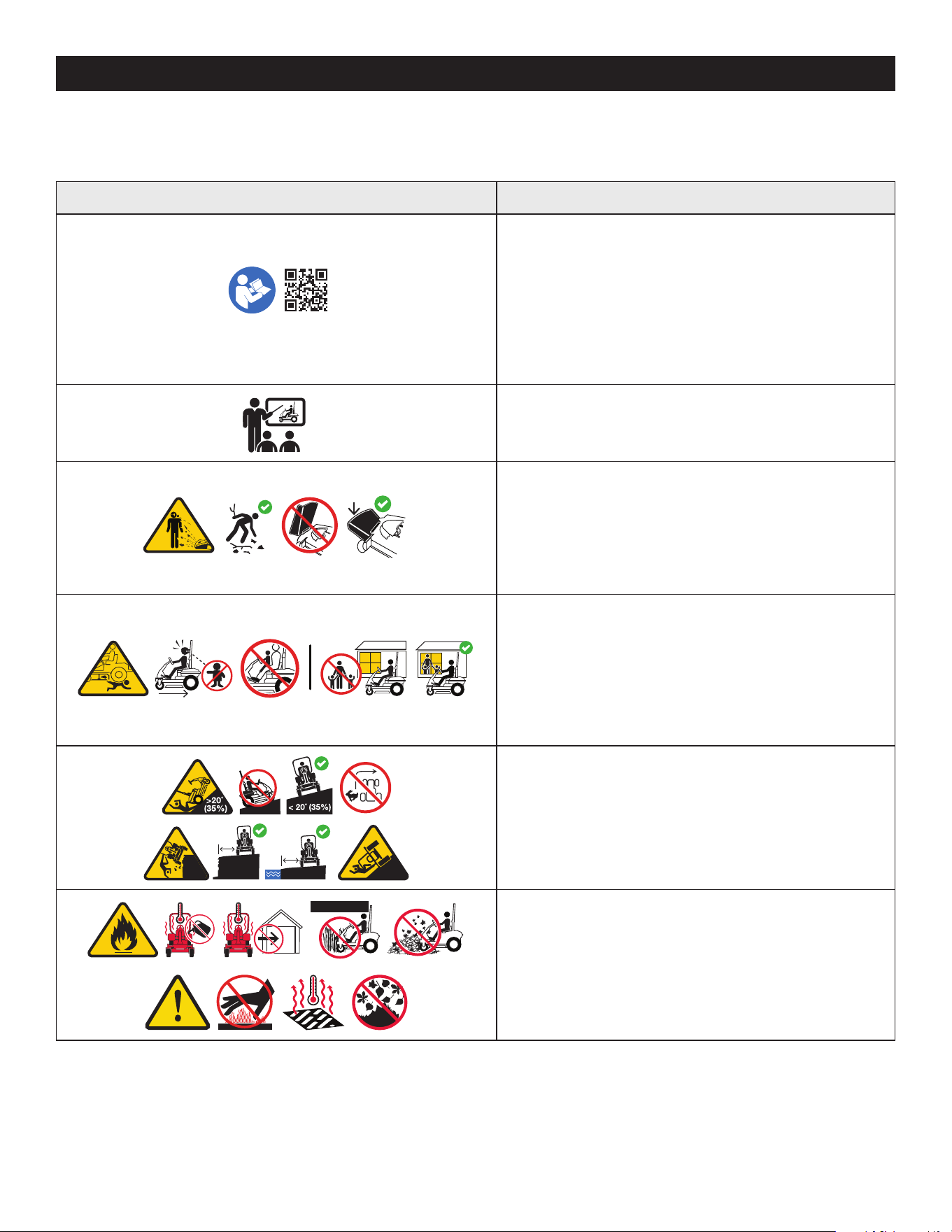
49
PRÁCTICAS DE OPERACIÓN SEGURAS
SÍMBOLOS DE SEGURIDAD
En esta página, se presentan y describen los símbolos de seguridad que pueden aparecer en este producto. Lea, comprenda y siga todas las instrucciones incluidas en la
máquina antes de intentar armarla y hacerla funcionar.
Símbolo Descripción
OPESymbol.com
ADVERTENCIA - LEA EL MANUAL DEL OPERADOR - Lea, entienda y cumpla
todas las normas y las instrucciones de seguridad que se incluyen en el manual y
en el tractor antes de intentar utilizar este tractor. Si no cumple con lo que indica
esta información, se pueden provocar lesiones personales o la muerte. Conserve
este manual en un lugar seguro para usarlo como referencia futura habitual.
Con un teléfono inteligente, escanee el símbolo del código de QR para obtener
más información sobre las advertencias incluidas en este tractor. También puede
visitar www.OPESymbol.com para obtener más información.
ADVERTENCIA - CAPACITACIÓN - Lea el Manual del Operador. No opere esta
cortadora de césped a menos que esté capacitado para ello.
ADVERTENCIA - EVITE LESIONES POR OBJETOS ARROJADOS - Mantenga a los
asistentes por lo menos a 75 pies (23 metros) de la máquina durante la operación.
Saque todas las piedras, palos, cables, huesos, juguetes y demás objetos extraños
que puedan ser recogidos y arrojados por las cuchilla(s). Nunca opere el tractor si
no está bien colocada la cubierta de descarga o si no está instalado el colector de
césped completo en el lugar que corresponde.
ADVERTENCIA - EVITE LESIONES EN NIÑOS AL RETROCEDER/POR
ATROPELLAR/POR CONTACTO CON LAS CUCHILLAS - Para evitar accidentes al
retroceder, siempre mire hacia atrás y hacia abajo para ver si hay niños. Nunca
transporte niños, ni siquiera con las cuchillas desactivadas. Mantenga a los
observadores, los niños y las mascotas en interiores durante la operación bajo la
atenta supervisión de un adulto responsable que no sea el operador. Detenga el
tractor si alguien entra en la zona.
>10ft (3m)>10ft (3m)
>10ft (3m)>10ft (3m)
ADVERTENCIA - EVITE LESIONES POR VUELCOS - No opere la máquina en
una pendiente mayor de 20° (35%). No corte el césped subiendo y bajando
pendientes, solo hágalo de forma transversal a las pendientes que son de
menos de 20° (35%). Utilice las velocidades bajas y evite los giros bruscos en las
pendientes. Manténgase a por lo menos 10 pies (3 metros) de barrancos, zanjas o
terraplenes o del borde del agua.
>10in (25c
m)
>10in (25
cm)
ADVERTENCIA - EVITE INCENDIOS - Su tractor fue diseñado para cortar césped
residencial normal, con una altura no mayor de 10” (25cm). No intente cortar
césped demasiado crecido, seco (como un pastizal) ni pilas de hojas secas. Deje
que el tractor se enfríe por lo menos cinco minutos antes de cargarle combustible
o guardarlo en un garaje cerrado o en una barraca de almacenamiento.
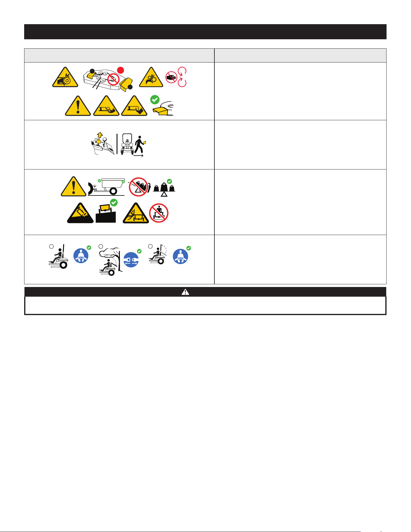
50
PRÁCTICAS DE OPERACIÓN SEGURAS
Símbolo Descripción
1
2
3
ADVERTENCIA - EVITE LESIONES DE AMPUTACIÓN - No ponga las manos
ni los pies cerca de las piezas rotatorias ni debajo de la plataforma de corte. El
contacto con las cuchilla(s) puede amputar manos y pies. Compruebe que todos
los dispositivos de seguridad (protecciones, escudos, interruptores, etc.) estén en
su lugar y funcionando. El contacto con las correas y/o el husillo de las cuchillas
puede aplastar o lesionar las partes del cuerpo.
ADVERTENCIA - SACAR LA LLAVE - Apague siempre las cuchillas, mueva las
palancas de control de la transmisión hacia afuera a la posición de freno de
mano, pare el motor y saque la llave antes de bajarse. Si va a dejar el tractor sin
supervisión, saque siempre la llave para evitar que niños u otras personas utilicen
el tractor sin autorización.
>5˚(9%)
<5˚(9%)
<50lb
<500lb(226kg)
(22kg)
ADVERTENCIA - EVITE LAS LESIONES RELACIONADAS CON EL REMOLQUE - No
remolque cargas que superen las 500 libras (226 kg) de peso de arrastre y nunca
supere las 50 libras (22 kg) de peso sobre el punto de enganche. Nunca permita
que los niños y otras personas se suban a equipos remolcados. No remolque en
pendientes de más de 5° (9%). En las pendientes, el peso del equipo remolcado
puede causar pérdida de tracción y pérdida de control, y/o de la capacidad para
detenerse. Desplácese lentamente y deje distancia adicional para detenerse.
1
2
3
ADVERTENCIA - EVITAR LESIONES GRAVES O LA MUERTE POR EL VUELCO
- Mantenga la barra antivuelco en posición vertical elevada con el cinturón de
seguridad abrochado. Baje la barra antivuelco y no se abroche el cinturón de
seguridad en situaciones de poco espacio libre. Levante la barra antivuelco y
abroche el cinturón de seguridad tan pronto como el espacio lo permita.
ADVERTENCIA
Su responsabilidad—Limite el uso de esta máquina motorizada a las personas que lean, comprendan y respeten las advertencias e instrucciones que figuran en este
manual y en la máquina. - ¡GUARDE ESTAS INSTRUCCIONES!
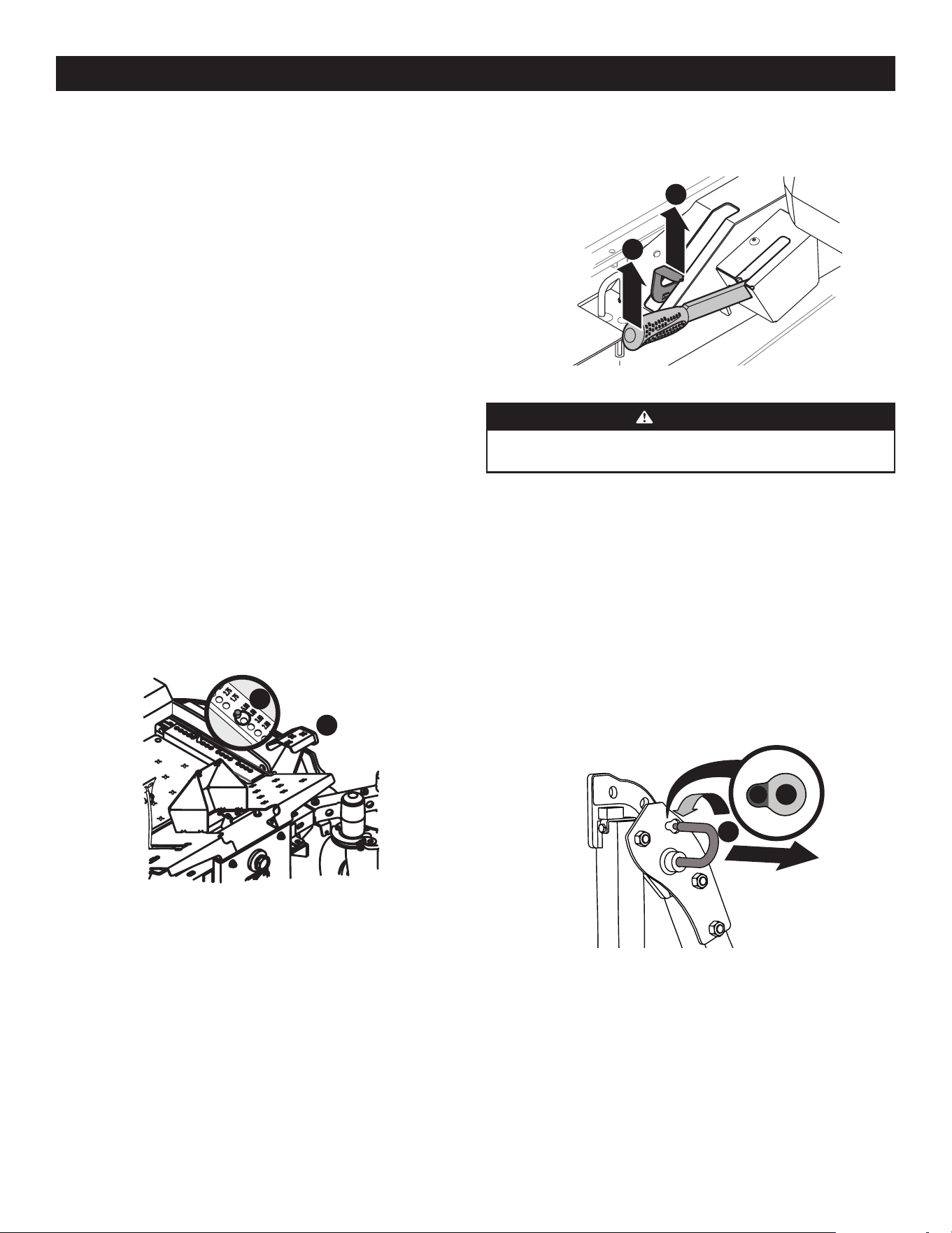
51
CONFIGURACIÓNCONFIGURACIÓN
CONTENIDO DE LA CAJA
• Cortadora con radio de giro cero (1)
• Volante (1)
• Paquete para montaje de perilla de inclinación de asiento y elementos de
ferretería (1)
• Elementos de ferretería para montaje de asiento (1)
• Elementos de ferretería para instalación de batería (1)
• Manual del Operador de la Cortadora (1)
• Manual del Operador del Motor (1)
NOTA: este manual de operación corresponde a varios modelos. Las características
de las cortadoras de césped pueden variar según los modelos. No todas las
características que se incluyen en este manual se aplican a todos los modelos de
cortadora de césped y la cortadora de césped que se ilustra aquí puede diferir de
la suya.
NOTA: todas las referencias que contiene este manual a los lados derecho o izquierdo
y trasero o delantero de la máquina son siempre desde la posición de operación. Las
excepciones, si las hubiere, serán especificadas.
PREPARACIÓN DE LA CORTADORA DE CÉSPED
HERRAMIENTAS NECESARIAS: anteojos de seguridad, guantes de
cuero, cortaalambres
1. Retire el material de embalaje superior del pálet de embarque, y corte cualquier
banda o fleje que fije la cortadora de césped al pálet.
2. Use el pedal de elevación de la plataforma (a) para elevar la plataforma hasta
su posición más alta y asegurarla en su lugar con el pasador de horquilla (b)
adosado a la cortadora. Consulte la Figura 1.
a
b
Figura 1
3. Las dos transmisiones hidrostáticas están equipadas con una válvula de
derivación que le permitirá mover manualmente la cortadora de césped en
distancias cortas.
4. Active las válvulas de derivación de las transmisiones tirando de la palanca
de derivación (a) hacia afuera y luego hacia arriba y otra vez todo para atrás.
Consulte la Figura 2.
a
b
Figura 2
ADVERTENCIA
No remolque la cortadora de césped, ni siquiera con las válvulas de
derivación activadas. La transmisión sufrirá graves daños.
5. Con cuidado, deslice la cortadora de césped fuera del pálet de embarque.
6. Para soltar la palanca de derivación (a), empuje la palanca hacia adelante.
Consulte la Figura 2.
7. Para activar el freno de mano, tire hacia atrás completamente de la palanca del
freno de mano (b). Consulte la Figura 2.
8. Corte cualquier precinto para cables que sostenga hacia arriba al deflector del
canal y deseche cualquier material de embalaje.
Sistema de Protección Antivuelco (ROPS)
1. Tire ligeramente hacia arriba del ROPS superior para aliviar cualquier
tensión sobre la chaveta de cierre (a) y gire la chaveta de cierre (a) de la
posición TRABADA (b) a la posición AJUSTE (c). Consulte la Figura 3. Repita el
procedimiento para la chaveta de cierre del lado opuesto.
a
b
c
Figura 3
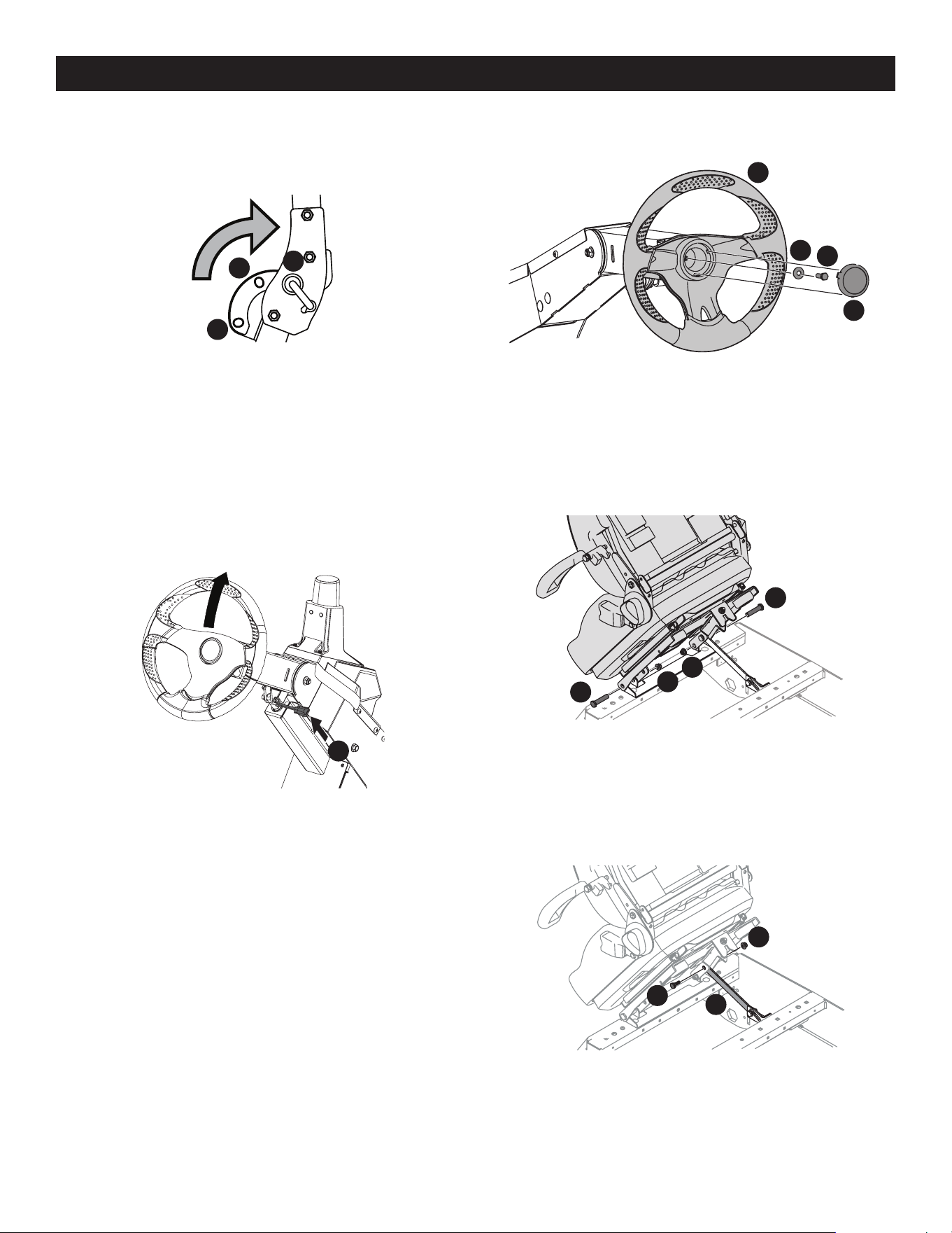
52
CONFIGURACIÓN
3. Coloque la arandela Belleville (c) sobre el volante (b) y ajústela con el tornillo de
seguridad hexagonal (d). Consulte la Figura 6.
a
b
c
d
Figura 6
4. Coloque la cubierta del volante encima del centro del volante y empuje hacia
abajo hasta que haga clic al encajar en su lugar.
ASIENTO DEL OPERADOR
1. Saque las dos tuercas de seguridad bridadas (b) y pernos con reborde (a) de la
bolsa del manual. Consulte la Figura 7.
a
a
b
b
Figura 7
2. Coloque el asiento en posición y fíjelo con los elementos de ferretería como se
muestra en la Figura 7.
3. Saque el tornillo con reborde (a) y la tuerca de seguridad bridada (b) de la bolsa
del manual e instale la ménsula de traba del asiento (c) como se muestra en la
Figura 8.
a
b
c
Figura 8
2. Cuando ambas chavetas de cierre estén fijas en la posición AJUSTE, levante
lentamente y gire el ROPS superior desde la posición TRANSPORTE (a), pasando
por la posición TRANSPORTE CON EMBOLSADORA (b) hasta llegar a la posición
FUNCIONAMIENTO (c). Consulte la Figura 4.
a
b
c
Figura 4
3. Gire ambas chavetas de cierre hasta la posición TRABADA. Mueva levemente el
ROPS superior hasta que las chavetas de cierre estén totalmente engranadas en
la posición TRABADA.
Columna del volante
La columna del volante se inclina totalmente hacia abajo para el embarque. Para
ajustar la columna, tire hacia arriba de la palanca de ajuste de la columna de
dirección (a) y mueva la columna de dirección hasta la posición deseada. Suelte la
palanca de ajuste de la columna de dirección (a) para que la columna de dirección
quede fija en la posición deseada. Consulte la Figura 5.
a
Figura 5
Volante
¡IMPORTANTE! No utilice herramientas de impacto para instalar o extraer el
volante. Si lo hace, puede ocasionar daños en componentes críticos de la dirección
de potencia.
1. Retire los elementos de ferretería para fijar el volante desde debajo del
casquete del volante (a). Con cuidado y haciendo palanca, levante el casquete
del volante (a) para retirar los elementos de ferretería. Consulte la Figura 6.
2. Con las ruedas de la máquina orientadas en línea recta hacia adelante, coloque
el volante (b) sobre el eje de dirección. Consulte la Figura 6.
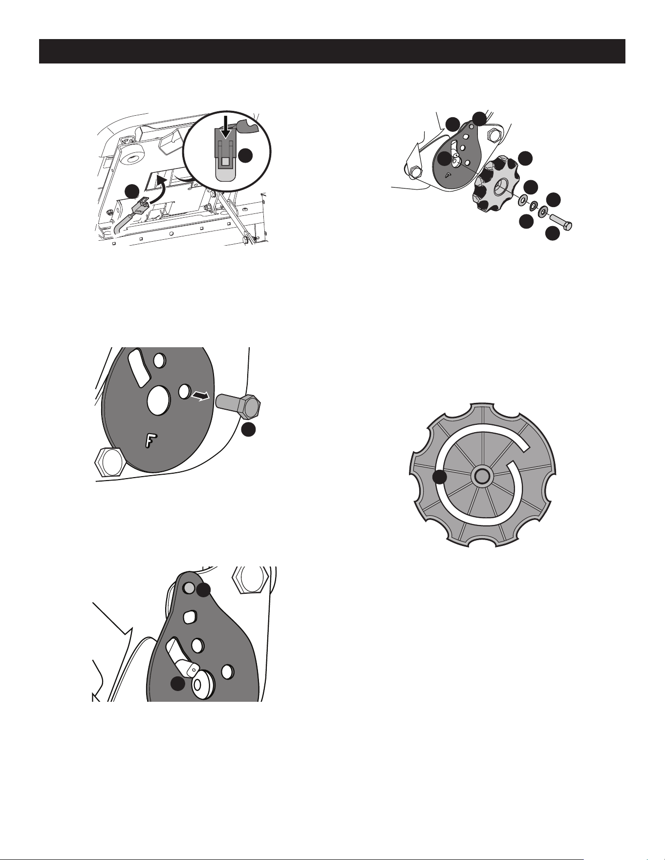
53
CONFIGURACIÓN
4. Inserte el mazo de cables (a) en la parte inferior del asiento como se muestra en
la Figura 9.
a
a
Figura 9
NOTA: al conectar el mazo de cables (a), asegúrese de empujar el exceso de
cable del mazo de cables (a) al interior del orificio de la caja del asiento antes de
continuar. Consulte la Figura 9.
5. Quite el tornillo (a) que fija la placa reclinable en la posición del respaldo del
asiento. Consulte la Figura 10.
a
Figura 10
6. Incline el asiento hacia adelante hasta la posición totalmente delantera. Vuelva
a colocar la placa reclinable con el perno de remache (a) y el pasador de la placa
reclinable (b) que pasa por la placa reclinable en los lugares que se muestran en
la Figura 11.
a
b
Figura 11
7. Saque el conjunto de perilla de inclinación del asiento de la bolsa e instálelo
como se muestra en la Figura 12.
a
b
c
d
e
f
h
g
Figura 12
NOTA: asegúrese de orientar la placa reclinable (a) y de instalar la arandela
de plástico (b), la arandela de resorte (c) y la arandela de metal (d) como se
muestra en la Figura 12. La arandela de plástico va en la parte de adentro.
8. Deslice la placa de cojinetes reclinable (a) en el pasador de la placa reclinable
(e). Consulte la Figura 12.
9. Luego alinee el espiral (a) en el interior de la perilla de la placa reclinable con
el pasador de la placa reclinable. Asegúrese de que el cubo que está en la parte
posterior de la placa reclinable se apoye correctamente en los orificios grandes
de la placa lateral. Consulte la Figura 13.
a
Figura 13
10. Con una llave ajuste el tornillo hexagonal (g) hasta que resulte difícil hacer girar
la perilla de la placa reclinable (f). Consulte la Figura 12.
NOTA: no utilice herramientas eléctricas para instalar.
11. Afloje gradualmente el tornillo hexagonal (g) hasta que la perilla de la placa
reclinable se mueva libremente. No afloje el tornillo hexagonal (g) más de una
vuelta completa. Consulte la Figura 12.
12. Instale la tuerca de 1/4” en el perno de remate (h) y rote la perilla de la placa
reclinable para comprobar el funcionamiento del asiento. Consulte la Figura 12.
AJUSTE DEL ASIENTO
Con el ajuste adecuado de la columna de dirección y el asiento se producirá lo
siguiente (para ajustar el asiento, consulte abajo):
En la posición neutral, con las manos sobre el volante,
• Los brazos del operador deben estar relajados y en posición
aproximadamente vertical.
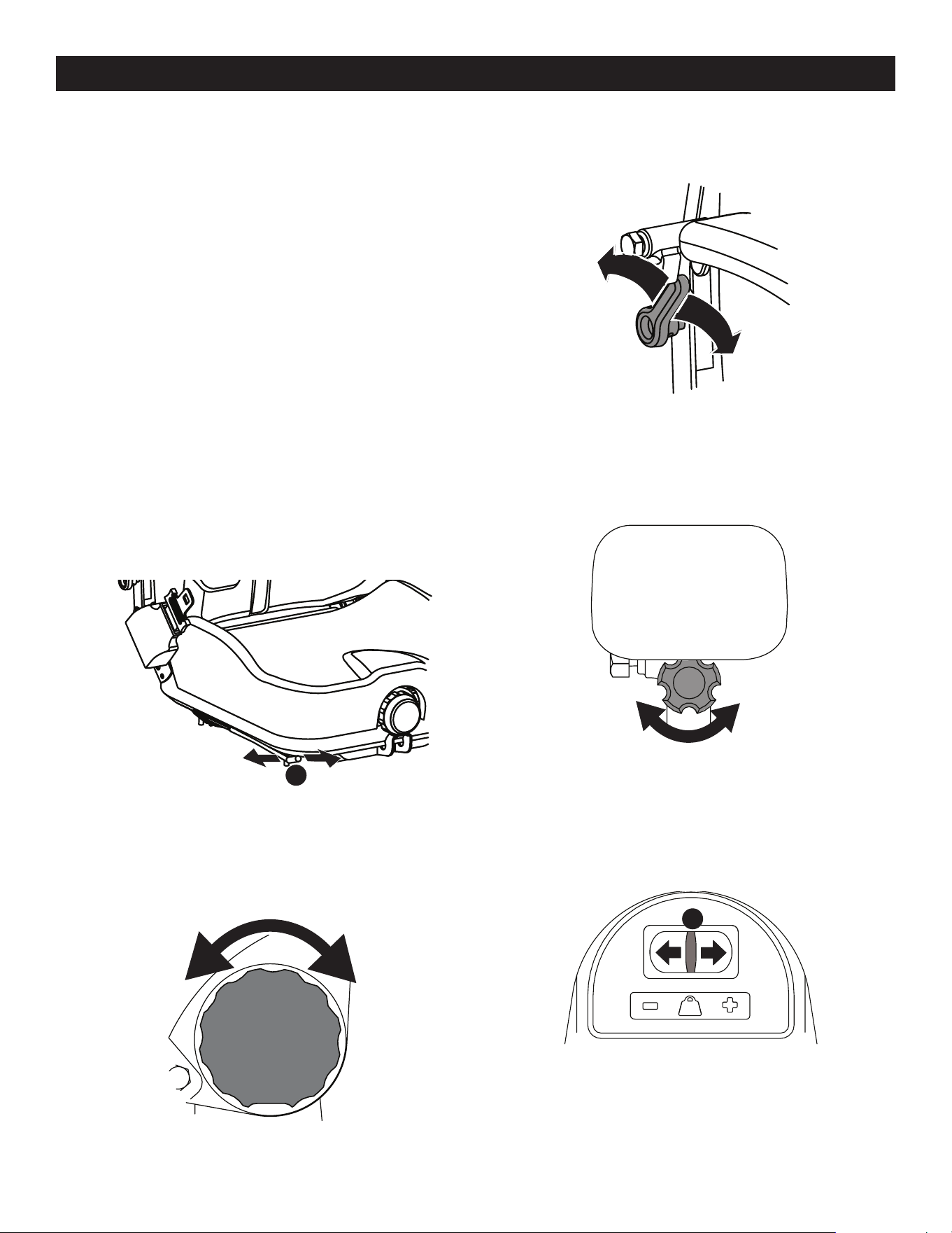
54
CONFIGURACIÓN
• Los antebrazos del operador deben estar en posición
aproximadamente horizontal.
• La espalda del operador debe estar en contacto con el respaldo del asiento.
• La columna de dirección no debe estar en contacto con las piernas del operador.
Compruebe los resultados de cualquier ajuste de las condiciones arriba descriptas.
Repita cualquier procedimiento de ajuste que sea necesario hasta que se cumplan
todas las condiciones.
Esta máquina está equipada con un asiento ajustable, que incluye un conjunto de
cinturón retráctil y un Sensor de Presencia del Operador (OPS). El OPS, que tiene
la forma de un interruptor, está integrado en la parte inferior del asiento y está
conectado al sistema eléctrico de la máquina. El OPS debe conectarse al mazo de
cables eléctricos.
El asiento se puede ajustar hacia adelante y atrás, los apoyabrazos pueden ajustarse
hacia arriba y abajo, y la suspensión neumática, un apoyo lumbar, puede ajustarse. El
asiento también se puede inclinar hacia adelante y atrás.
NOTA: la base del asiento debe fijarse con la traba, de lo contrario, el conjunto del
asiento podría inclinarse hacia adelante.
Posición del asiento
Para mover el asiento hacia adelante o atrás, localice la varilla de ajuste del asiento
(a) que se encuentra debajo del asiento. Mueva la varilla hacia la izquierda, deslice
el asiento hacia adelante o atrás hasta la posición deseada y una vez allí, suelte la
varilla. Consulte la Figura 14.
a
Figura 14
Inclinación del asiento
La inclinación del asiento se controla con la perilla que está a la izquierda del asiento.
Gire la perilla hacia atrás para inclinar el asiento hacia atrás, y gire la perilla hacia
adelante para inclinar el asiento hacia adelante. Consulte la Figura 15.
Figura 15
Apoyo lumbar
Para modificar el apoyo lumbar, mueva hacia arriba o hacia abajo la palanca que está
a la derecha del asiento. Consulte la Figura 16.
Figura 16
Apoyabrazos
Para ajustar la altura de los apoyabrazos, levante el apoyabrazos y gire hacia la
derecha o izquierda la perilla que está debajo del apoyabrazos para aumentar o
disminuir la altura. Consulte la Figura 17.
Figura 17
Suspensión neumática del asiento
La suspensión neumática puede ajustarse hacia arriba o abajo con la palanca de
ajuste de altura (a) que está en el frente del asiento. Presione la palanca hacia la
izquierda (+) para subir la altura y hacia la derecha (-) para bajar la altura del asiento.
Consulte la Figura 18.
a
Figura 18
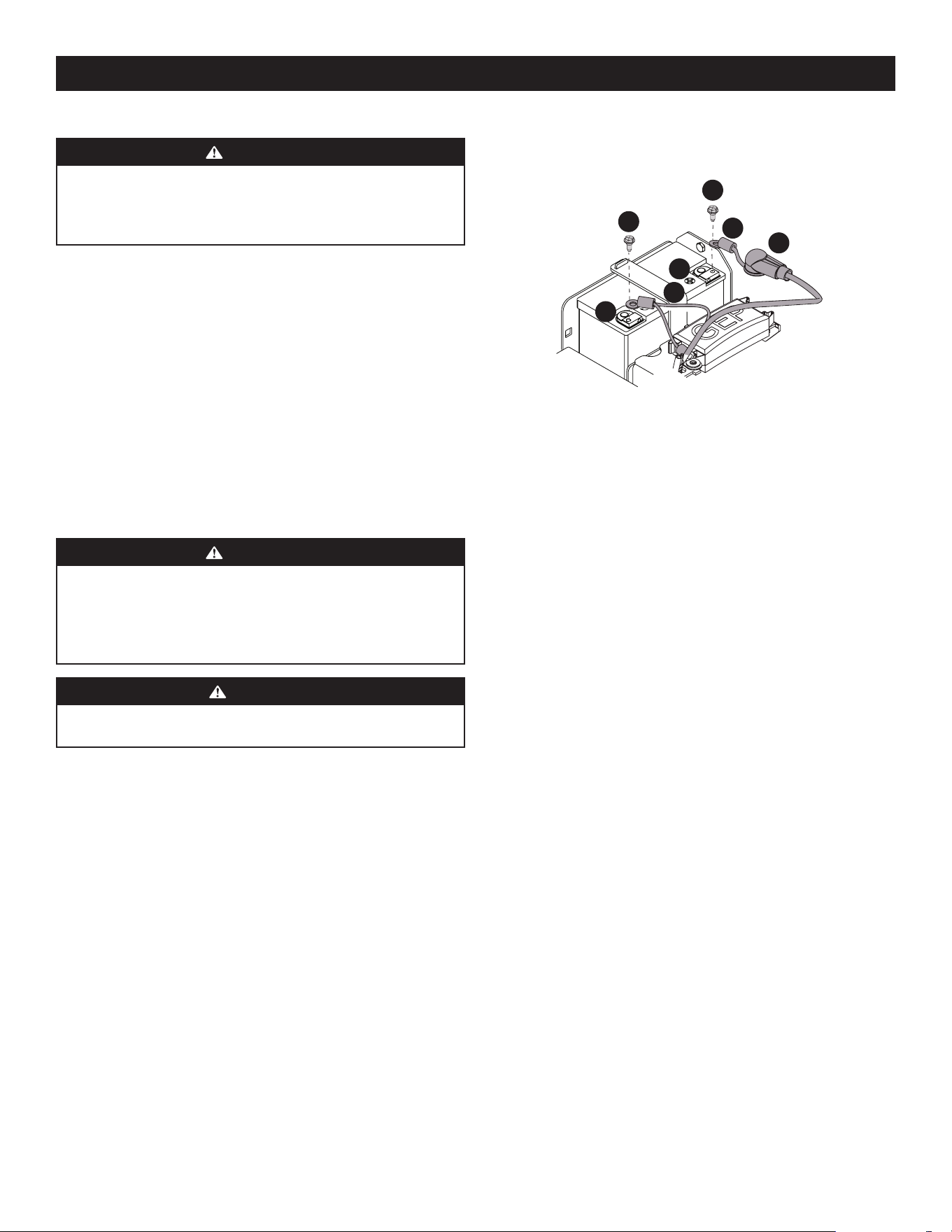
55
CONFIGURACIÓN
CONTROL DE LA PRESIÓN DE LOS NEUMÁTICOS
ADVERTENCIA
La presión máxima de los neumáticos en cualquier circunstancia es de 12
psi en los neumáticos traseros y 25 psi en los neumáticos delanteros. Se
debe mantener una presión uniforme para todos los neumáticos en todo
momento.
PRESIÓN DE INFLADO
Neumáticos traseros - 10-12 psi máx.
Neumáticos delanteros - 20-25 psi máx.
Es posible que los neumáticos de su cortadora de césped se hayan inflado en exceso
para transportarla. Reduzca la presión de los neumáticos antes de hacer funcionar
la cortadora. La presión recomendada para los neumáticos con la cortadora en
funcionamiento es 10-12 psi para los neumáticos traseros y 20-25 psi para los
neumáticos delanteros.
PUNTOS DE LUBRICACIÓN Y ENGRASE
Antes de utilizar la cortadora de césped, consulte la sección Cuidado del producto de
este manual para comprobar los puntos de lubricación y engrase. Lubrique y engrase
si es necesario.
CONEXIÓN DE LOS CABLES DE LA BATERÍA
ADVERTENCIA
PROPOSICIÓN 65 DE CALIFORNIA: Los contactos, bornes y accesorios
afines de las baterías contienen plomo y compuestos de plomo, sustancias
químicas que según lo establecido por el Estado de California causan cáncer
y problemas reproductivos. Lávese las manos después de estar en contacto
con estos componentes.
PRECAUCIÓN
Cuando coloque los cables de la batería, conecte siempre primero el cable
POSITIVO (rojo) a su borne, y a continuación el cable NEGATIVO (negro).
Por razones relacionadas con el embarque, los dos cables de la batería de su equipo
pueden haber sido desconectados de los bornes en fábrica. Para conectar los cables
de la batería, proceda de la siguiente manera:
1. Levante la palanca que está a cualquiera de los lados del respaldo del asiento,
e incline el asiento hacia adelante trabándolo en su lugar con el puntal del
asiento. Saque los pernos y las tuercas hexagonales de la bolsa del manual.
NOTA: el borne positivo de la batería está marcado como POS. (+) (a). El borne
negativo de la batería está marcado como NEG. (–) (b). Consulte la Figura 19.
NOTA: si el cable positivo de la batería (c) ya está conectado, siga con el paso 4.
2. Deslice el manguito rojo (d) para retirarlo del borne positivo de la batería
(a) y conecte el cable rojo (c), con el perno de montaje vertical (e). Consulte
Figura 19.
a
b
c
d
e
e
f
Figura 19
3. Coloque el manguito rojo (d) sobre el borne positivo de la batería (a) para
aislarlo y protegerlo contra la corrosión.
4. Conecte el cable negro (f) al borne negativo de la batería (b) con el perno de
montaje vertical (e). Consulte la Figura 19.
NOTA: si la batería se pone en servicio después de la fecha indicada en su
parte superior o al costado de la misma, cárguela antes de hacer funcionar
la máquina.
CONEXIÓN A LA RED GPS
Consulte las instrucciones para la conexión a la red GPS en la sección Operación.
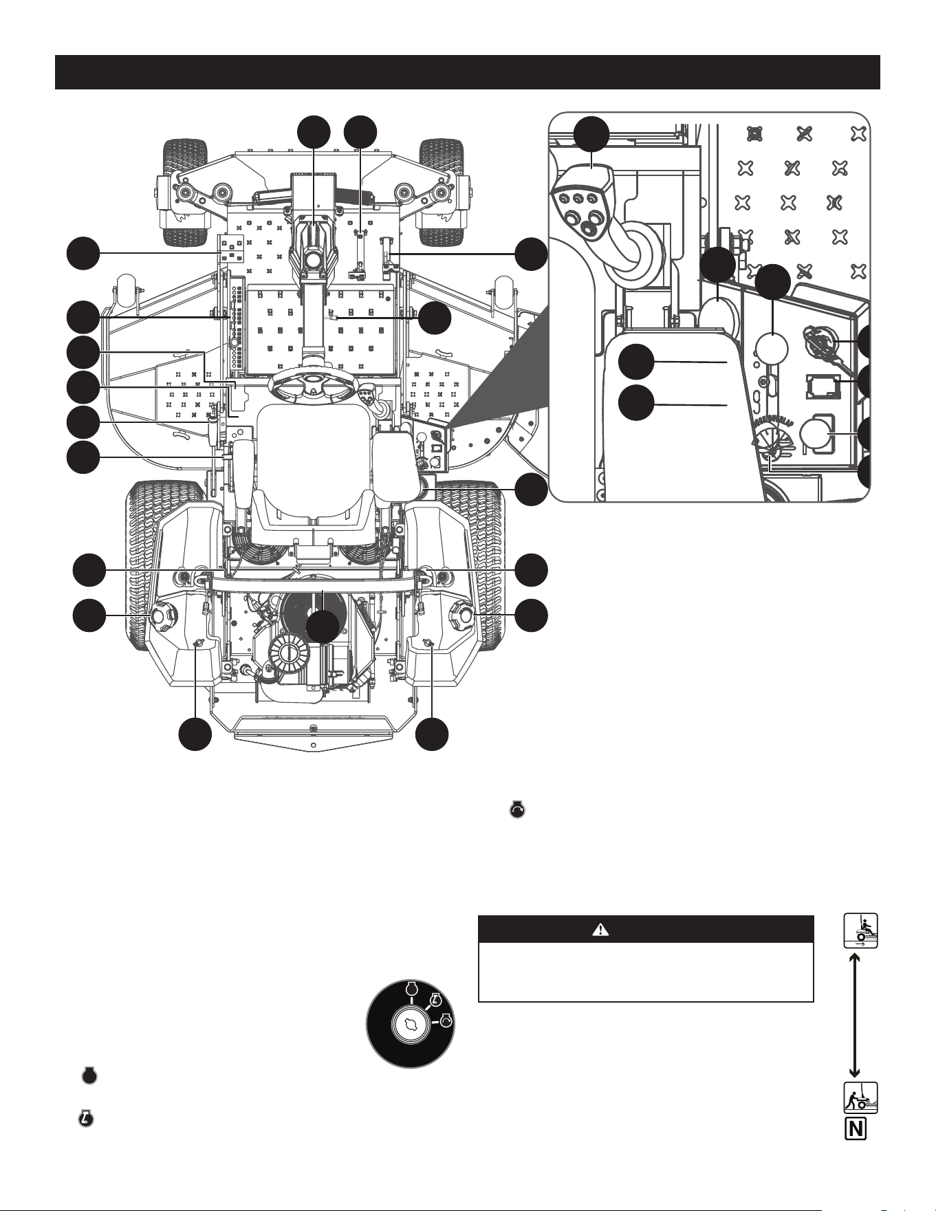
56
OPERACIÓNOPERACIÓN
NOTA: todas las referencias que contiene este manual a los lados derecho o izquierdo
y trasero o delantero de la máquina son siempre desde la posición de operación. Las
excepciones, si las hubiere, serán especificadas.
NOTA: este Manual del Operador corresponde a varios modelos. Las características
de las cortadoras de césped pueden variar según los modelos. No todas las
características que se incluyen en este manual se aplican a todos los modelos de
cortadora de césped y la cortadora de césped que se ilustra aquí puede diferir de
la suya.
A. ENCENDIDO
El interruptor de encendido está ubicado en la consola del lado
derecho, en la parte posterior del control del acelerador. El
interruptor de encendido tiene tres posiciones, según se indica
a continuación:
STOP
STOP
(parada)- El motor y el sistema eléctrico
están apagados.
RUN (funcionamiento) - El sistema eléctrico de la cortadora está energizado.
STOP
AD I
J
W
X
AB
†
K
AC
B
AB
†
K
AC
Y
H
S
G
†
U
†
T
†
Z
AA
†
D
C
F
A
E
†
AB
†
AE
Figura 20
START (arranque) - El motor del arrancador enciende el motor. Suelte la llave
inmediatamente apenas arranque el motor.
NOTA: para evitar el arranque accidental y/o la descarga de la batería, quite la llave
del interruptor de encendido cuando la cortadora de césped no se encuentre en uso.
B. PALANCA DE DERIVACIÓN DE TRANSMISIÓN
ADVERTENCIA
No remolque la cortadora de césped, ni siquiera con las válvulas
de derivación activadas. Si lo hace, la transmisión sufrirá
graves daños.
La palanca de derivación de transmisión se encuentra junto a la consola
del lado izquierdo, a la izquierda del asiento del operador.
Cuando está activada, las válvulas abren una derivación dentro de las
transmisiones hidrostáticas. Consulte la sección Operación para obtener
instrucciones sobre el uso de la función de derivación.
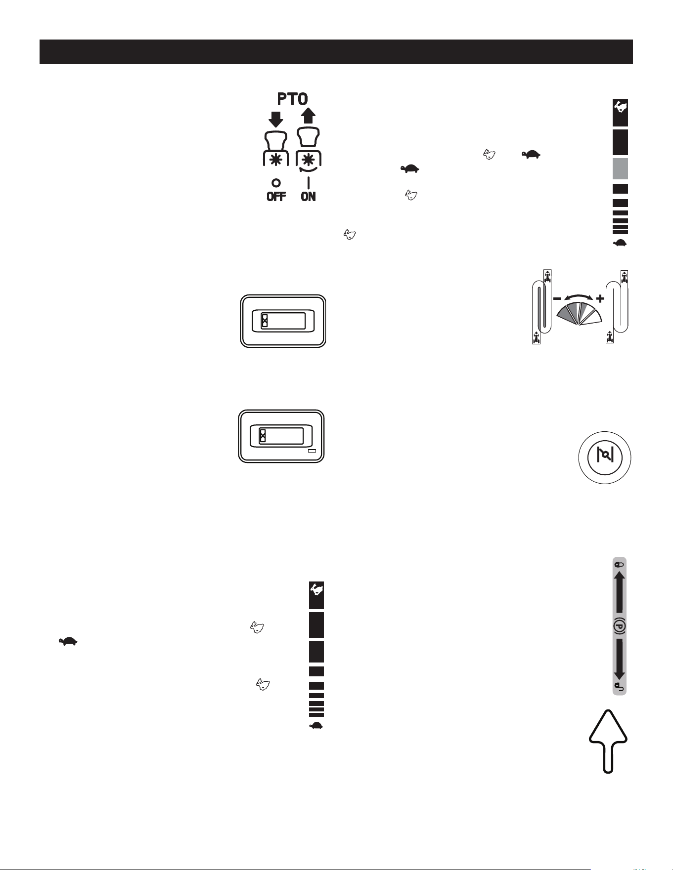
57
OPERACIÓN
C. PERILLA DE LA TOMA DE FUERZA (PTO)
La perilla de la PTO está ubicada en la consola del lado
derecho, a la derecha del asiento del operador.
La perilla de la PTO hace funcionar el embrague eléctrico de la
PTO que está montado en la base del cigüeñal del motor. Tire
de la perilla hacia arriba para engranar el embrague de la PTO,
o empuje la perilla hacia abajo para desengranar el embrague.
Al arrancar el motor, la perilla de la PTO debe estar en
posición “OFF”.
D. MEDIDOR HORARIO Y RECORDATORIO DE SERVICIO
El medidor horario y recordatorio de servicio está ubicado en la consola del lado
derecho, a la derecha del asiento del operador. Registra las horas de funcionamiento
del cortacésped y la velocidad del motor (RPM) en la pantalla digital.
Medidor horario (si está equipado)
El medidor horario se activa cuando el interruptor de
encendido se coloca en posición "ON" (encendido). Lleve
el registro de las horas reales de funcionamiento para
asegurar que se realicen todos los procedimientos de
mantenimiento según las instrucciones de este manual
del operador y del manual del motor.
El medidor horario y recordatorio de servicio con botón MODE (si
está equipado)
El medidor horario y recordatorio de servicio se activa
al poner el interruptor de encendido en posición ON.
Lleve el registro de las horas reales de funcionamiento
para asegurar que se realicen todos los procedimientos
de mantenimiento según las instrucciones de este
manual del operador y del manual del motor. El medidor horario y recordatorio de
servicio está equipado con un botón de modo (MODE) que puede alternar entre las
funciones disponibles y puede usarse para restablecer las alertas de servicio. Cuando
la máquina esté en el modo de alerta de servicio o en un modo de alarma de servicio
mantenga presionado el botón de modo (MODE) durante 3 segundos para reiniciar.
E. ACELERADOR
Acelerador manual (si se incluye)
El control del acelerador está ubicado en la consola del lado derecho, a
la derecha del asiento del operador. Cuando se lo coloca en determinada
posición, se mantiene una velocidad de motor uniforme. El control del
acelerador se mueve entre las posiciones de velocidad RÁPIDA y
lenta .
Empuje la manija de control del acelerador hacia adelante para aumentar
la velocidad del motor. La cortadora de césped está diseñada para operar
con el control del acelerador en la posición de velocidad RÁPIDA
(aceleración máxima) cuando la cortadora se desplaza con la plataforma de
corte acoplada.
Tire de la manija de control del acelerador hacia atrás para reducir la
velocidad del motor.
0.0
0.0
Palanca del acelerador electrónico (regulador electrónico) (si
se incluye)
La palanca del acelerador electrónico (regulador electrónico) se usa para
controlar la velocidad del motor y las RPM. También ayuda a controlar la
eficiencia del combustible. La palanca del acelerador electrónico se mueve
entre las posiciones de velocidad RÁPIDA y lenta . La posición de
velocidad LENTA se usa para el transporte básico de la cortadora con
la PTO desacoplada y consume el mínimo de combustible. La posición de
velocidad RÁPIDA debe usarse cuando la PTO está acoplada y consume
el máximo de combustible. La cortadora debe arrancarse en la posición
ARRANQUE pero siempre debe estar en la posición de velocidad RÁPIDA
cuando se está usando la PTO/plataforma.
F. PERILLA DE ANCHURA DE CORTE
La perilla de anchura de corte, únicamente disponible
cuando la cortadora está en modo Conducción
Automática SurePath, se encuentra en la consola del
lado derecho, a la derecha del asiento del operador y
tiene cuatro posiciones. La posición MÁS EFICIENTE es
adecuada para la mayoría de los terrenos y mantiene
un traslape estándar de pasadas de corte. Gire el
dial progresivamente de derecha a izquierda si está trabajando bajo condiciones
extremas o si observa secciones visibles de césped sin cortar cuando la cortadora está
en la posición MÁS EFICIENTE.
G. PERILLA DEL CEBADOR (SI SE INCLUYE)/LUZ INDICADORA
MULTIFUNCIÓN (MIL) (SI SE INCLUYE)
Perilla del cebador (si se incluye) - La perilla del cebador se
encuentra del lado izquierdo de la cortadora, junto al asiento
del operador. Tire de la perilla hacia afuera para cebar el motor;
empuje la perilla hacia adentro para abrir el cebador. El tener el
cebador en la posición ON ayuda al motor a arrancar durante el arranque inicial.
Durante el funcionamiento normal, el cebador debe estar en la posición OFF.
MIL (si se incluye) - La Luz Indicadora Multifunción (MIL) proporciona información
de diagnóstico sobre el motor. Si la MIL se enciende y/o parpadea consulte el manual
de servicio o comuníquese con su centro de servicio.
H. PALANCA DEL FRENO DE MANO
La palanca del freno de mano se encuentra a la izquierda del asiento del
operador. Al tirar de la palanca hacia arriba el freno de mano se activa, y al
empujarla hacia abajo se desactiva el freno.
NOTA: si el pedal de marcha adelante o atrás está activado al aplicar el
freno de mano, el motor se detendrá. El freno de mano debe estar aplicado
al encender el motor.
I. PEDAL DE MARCHA ADELANTE
El pedal de marcha adelante está ubicado en el lado derecho de la
máquina, directamente a la derecha de la columna de dirección y
sobre el estribo. Presione el pedal de marcha adelante hacia adelante
para que la cortadora se mueva en esa dirección. La velocidad
absoluta también se controla con el pedal de marcha adelante.
Cuanto más se presione el pedal hacia adelante, más rápido se
moverá la cortadora. El pedal volverá a su posición original/neutral
cuando no esté presionado.
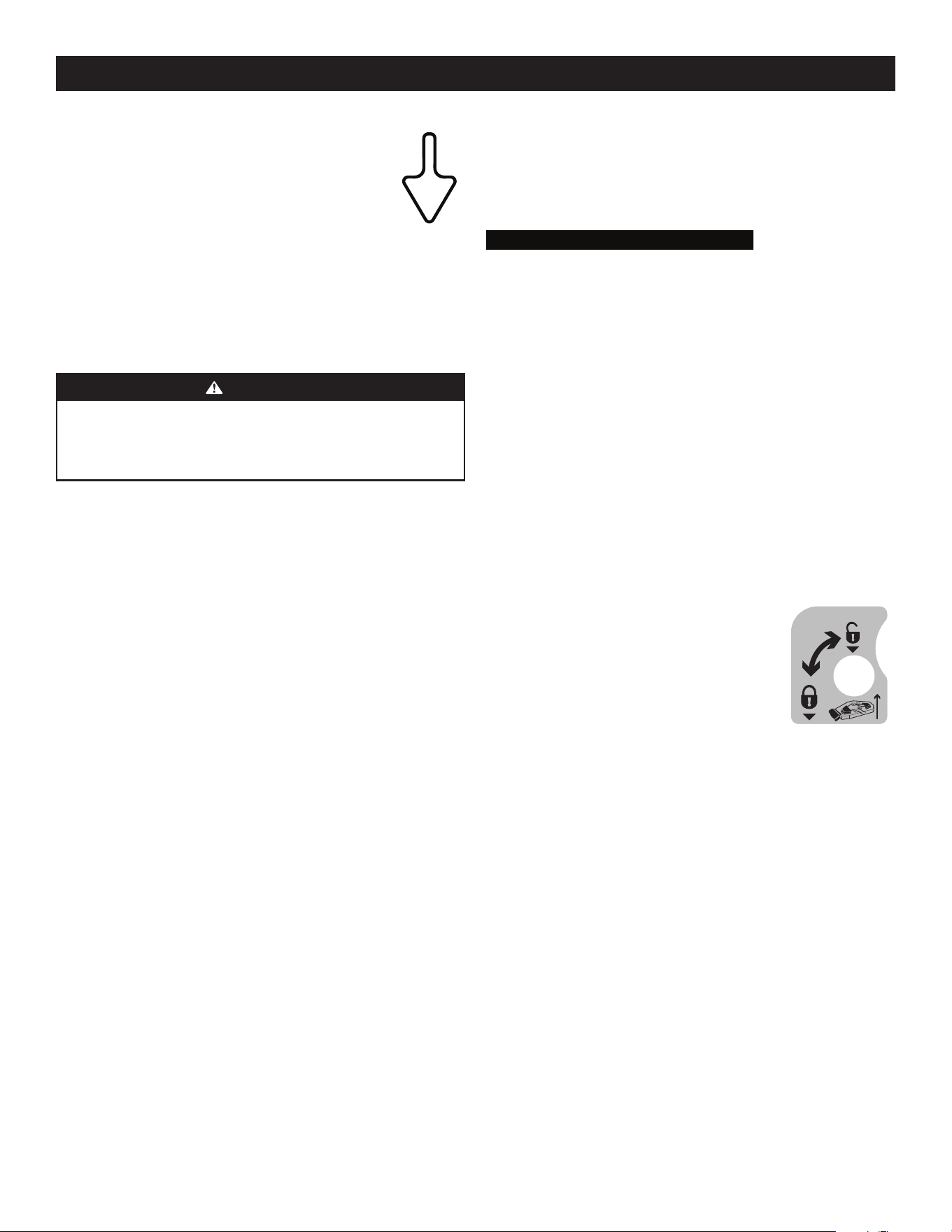
58
OPERACIÓN
R. TRABA DEL ASIENTO (NO SE MUESTRA)
La traba del asiento se encuentra debajo del centro trasero del asiento del operador.
La traba se usa para fijar el asiento en la posición de funcionamiento. Levante la traba
e incline el asiento hacia adelante para acceder al área debajo del asiento.
S. POSICIONAMIENTO DE LA ALTURA DE LA PLATAFORMA
El mecanismo de posicionamiento de la altura de la plataforma consiste en
varios orificios ubicados del lado izquierdo de la base para los pies. Cada orificio
corresponde a 1/4” de variación en la posición de la altura de la plataforma de corte,
en un rango que va desde 1” en la muesca más baja hasta 5” en la muesca más alta.
T. ELEVACIÓN DE LA PLATAFORMA
Pedal de elevación de la plataforma (si se incluye)
El pedal de elevación de la plataforma se encuentra en el extremo frontal izquierdo
de la base para los pies, y se usa para subir y bajar la plataforma de corte.
Para subir la plataforma de corte a la posición de transporte, empuje el pedal a
fondo hasta que la traba de transporte de la plataforma encaje en posición. Para
quitar la plataforma de la posición de transporte, presione el pedal de elevación
de la plataforma y levante la varilla de traba de la plataforma. Para posicionar
la plataforma, presione el pedal a fondo, quite el pasador de horquilla, vuelva a
insertarlo en la altura de corte deseada y lentamente quite presión sobre el pedal
hasta que llega al pasador de horquilla.
U. TRABA DE TRANSPORTE (SI SE INCLUYE)
La traba de transporte se encuentra del lado izquierdo del
asiento del operador y se usa para trabar la plataforma en
la posición de transporte. Presione hacia abajo el pedal de
elevación de la plataforma, levante la barra de bloqueo
de transporte de la placa de presión y gírela en sentido
contrario a las agujas del reloj hasta que el extremo libre
caiga en el orificio abierto para bloquear la plataforma.
Para liberar la plataforma, invierta el proceso.
V. DEPÓSITO DE EXPANSIÓN DEL ACEITE DE TRANSMISIÓN (NO
SE MUESTRA, SI SE INCLUYE)
La serie 900 está equipada con un depósito de expansión del aceite de transmisión
ubicado debajo del asiento, y conectado por mangueras a los conjuntos de
transmisión del lado derecho e izquierdo. La función del depósito es contener
la expansión natural del aceite de transmisión que se produce a medida que la
transmisión se calienta durante el funcionamiento de la máquina. NO LLENE
EL DEPÓSITO.
En condiciones operativas normales, no se debe agregar aceite al depósito. El nivel
de aceite FRÍO debe estar aproximadamente 1/4” por encima de la base del depósito
en los modelos 900. Consulte la sección Cuidado del producto de este manual para
obtener más información sobre los depósitos de expansión del aceite de transmisión.
NOTA: antes del funcionamiento inicial de la cortadora de césped, el nivel de aceite
del depósito puede estar levemente por encima del máximo debido a la presencia
de aire en los circuitos de aceite. El funcionamiento de la cortadora de césped con el
tiempo purgará el aire de las líneas y el nivel de aceite se estabilizará en el máximo.
4.50
"
3.
5
0"
2.50"
1.
5
0"
4.75"
3.75"
2.75
"
1.75"
5
"
4
"
3"
2"
1"
3.25"
4.
25
"
2.25
"
1.2
5
"
J. PEDAL DE MARCHA ATRÁS
El pedal de marcha atrás está ubicado del lado derecho de la
cortadora, a la derecha del pedal de marcha adelante, y sobre el
estribo. La velocidad absoluta también se controla con el pedal
de marcha atrás. Cuanto más se presione el pedal hacia abajo,
más rápido se moverá la cortadora. El pedal volverá a su posición
original/neutral cuando no esté presionado.
K. TAPONES DEL DEPÓSITO DE COMBUSTIBLE
Los tapones del depósito del combustible se encuentran por encima del depósito del
combustible a la izquierda y derecha del asiento. Gire el tapón en sentido contrario
a las agujas del reloj para quitarlo y en sentido de las agujas del reloj hasta que
haga clic tres veces para ajustarlo. Siempre vuelva a colocar el tapón del depósito de
combustible bien ajustado después de quitarlo.
ADVERTENCIA
Nunca llene el depósito de combustible si el motor está en funcionamiento.
Si el motor está caliente por haber funcionado hasta hace poco, déjelo
enfriar varios minutos antes de cargar combustible. La gasolina es muy
inflamable y podría salpicar el motor y causar un incendio.
L. PALANCA DE AJUSTE DEL ASIENTO (NO SE MUESTRA)
La palanca de ajuste del asiento está ubicada debajo del asiento, adelante a la
derecha. La palanca permite ajustar el asiento del operador hacia adelante o hacia
atrás. Consulte la sección Operación para ver instrucciones sobre el ajuste de la
posición del asiento.
M. PERILLA DE INCLINACIÓN DEL ASIENTO (NO SE MUESTRA)
La perilla de inclinación del asiento se encuentra del lado izquierdo del asiento.
Consulte la sección Operación para ver instrucciones sobre el ajuste de la inclinación
del asiento.
N. PERILLAS DE ALTURA DEL APOYABRAZOS (NO SE
MUESTRAN, SI SE INCLUYEN)
Las perillas de altura del apoyabrazos se encuentran debajo de los brazos del asiento
y se pueden usar para ajustar la altura de los apoyabrazos. Consulte la sección
Operación para ver instrucciones sobre el ajuste de la posición del apoyabrazos.
O. MECANISMO DE SUSPENSIÓN MECÁNICA (NO SE MUESTRA,
SI SE INCLUYE)
El mecanismo de suspensión mecánica se encuentra en el frente del asiento y se lo
puede ajustar para un rango de peso de los operadores de entre 125 y 275 libras.
Consulte la sección Operación para ver instrucciones sobre el ajuste del mecanismo
de suspensión mecánica.
P. PALANCA DE APOYO LUMBAR (NO SE MUESTRA, SI
SE INCLUYE)
La palanca de apoyo lumbar se encuentra del lado derecho del asiento sobre el
respaldo del asiento. Consulte la sección Operación para ver instrucciones sobre el
ajuste del apoyo lumbar.
Q. PUNTAL DEL ASIENTO (NO SE MUESTRA)
El puntal del asiento e encuentra del lado izquierdo y trasero del asiento del
operador. Se utiliza para adelantar el asiento.
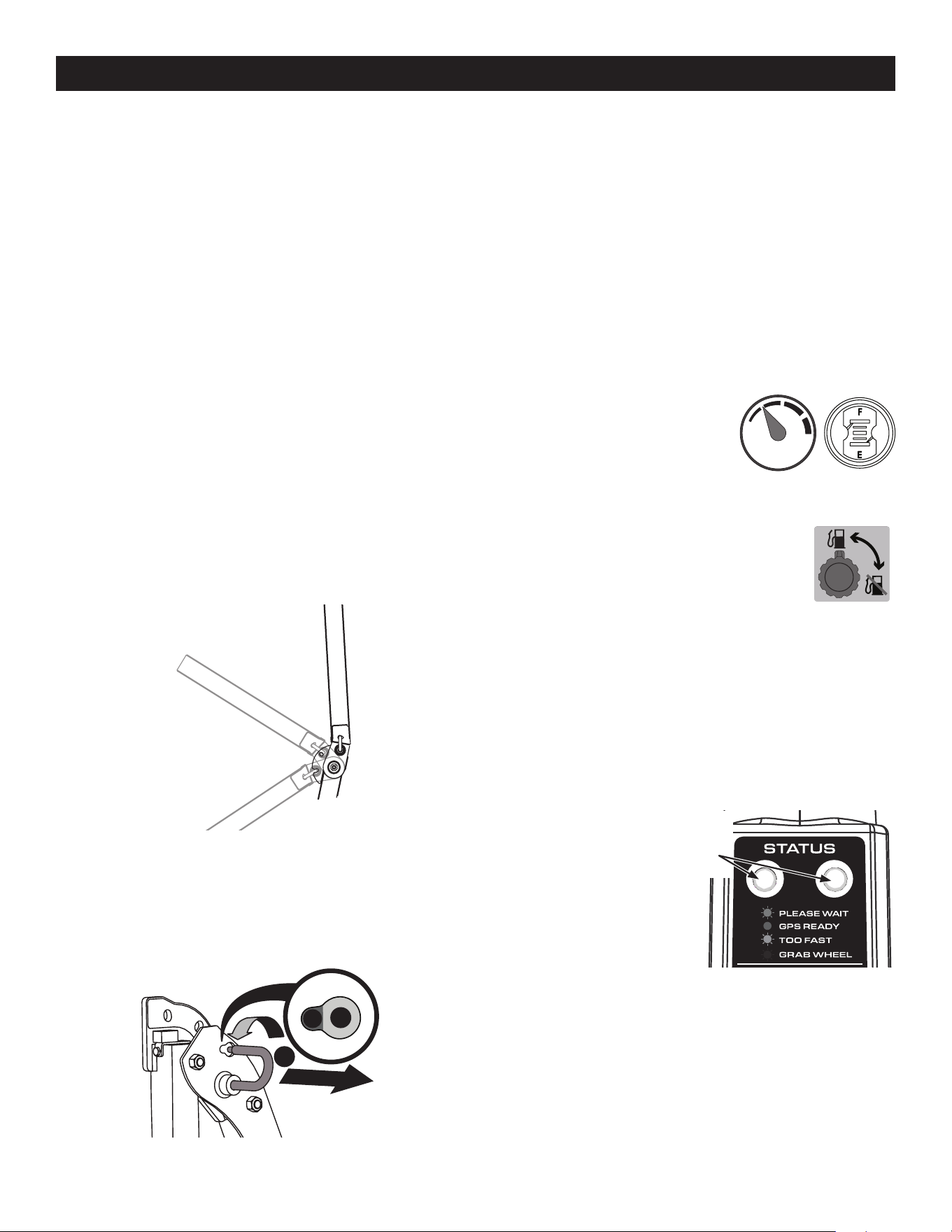
59
OPERACIÓN
W. PALANCA DE AJUSTE DE LA COLUMNA DE DIRECCIÓN
La palanca de ajuste de la columna de dirección está ubicada a la derecha de la
columna de dirección. Para ajustar la columna, tire hacia arriba de la palanca de
ajuste de la columna de dirección y mueva la columna de dirección hasta la posición
deseada. Suelte la palanca de ajuste de la columna de dirección para que la columna
de dirección quede fija en la posición deseada.
X. PORTAVASOS
El portavasos se encuentra entre el depósito de combustible y el panel de control a la
derecha del asiento.
Y. ESTRUCTURA DE PROTECCIÓN ANTIVUELCO (ROPS)
Posiciones de la ROPS
Consulte las tres (3) posiciones de la ROPS en la Figura 21 y en las siguientes
descripciones y usos.
• TRANSPORTE: sólo para usar cuando esté transportando la cortadora o cuando
se la deba plegar momentáneamente para evitar contacto con elementos como
ramas de árboles, sogas para colgar ropa, retenidas de alambre, postes de
servicios públicos, edificios, etc.
• TRANSPORTE CON EMBOLSADORA: Permite bajar la ROPS para situaciones
descriptas para la posición de TRANSPORTE cuando la cortadora está equipada
con una embolsadora.
• OPERACIÓN: la ROPS siempre debería estar en esta posición cuando esté en
operación a menos que surjan las situaciones indicadas en las descripciones
TRANSPORTE y TRANSPORTE CON EMBOLSADORA.
Posición Transporte
Posición Transporte
con Embolsadora
Posición Operación
Figura 21
1. Para cambiar la posición de la ROPS, tire ligeramente hacia arriba de/empuje
hacia adelante la ROPS superior para aliviar cualquier tensión sobre la chaveta
de cierre (a) y gire la chaveta de cierre (a) de la posición TRABADA (b) a la
posición AJUSTE (c). Repita el procedimiento para la chaveta de cierre del lado
opuesto. Consulte la Figura 22.
a
b
c
Figura 22
2. Mueva la ROPS a la posición deseada. Las tres posiciones son TRANSPORTE,
TRANSPORTE CON EMBOLSADORA y OPERACIÓN. Consulte la Figura 21.
3. Gire ambas chavetas de cierre hasta la posición TRABADA. Mueva levemente la
ROPS superior hasta que las chavetas de cierre estén totalmente engranadas en
la posición TRABADA.
Z. TOMACORRIENTES PARA ACCESORIOS
Los dos tomacorrientes para accesorios opcionales están en la consola del lado
derecho. Consulte información en la sección Componentes y accesorios.
AA. TOMACORRIENTE DE 12 V (SI SE INCLUYE)
El tomacorriente de 12 V se encuentra a la derecha del asiento del operador sobre el
panel inferior de la consola del lado derecho y se usa para enchufar accesorios que
requieren una fuente de alimentación con una carga máxima de 5A en 12 V.
AB. INDICADOR(ES) DE COMBUSTIBLE
Hay un indicador de combustible arriba de cada
uno de los dos depósitos de combustible o un único
indicador a la derecha del asiento del operador
sobre la consola del lado derecho. Los indicadores
miden el nivel de combustible que hay en cada depósito.
AC. VÁLVULAS DE COMBUSTIBLE
Las válvulas de combustible se encuentran cerca de la parte
trasera de cada tanque de combustible. Las válvulas controlan el
flujo de combustible del depósito derecho e izquierdo y también
pueden interrumpir el flujo de combustible al motor. Para abrir
el flujo desde el o los depósitos, gire la válvula en sentido contrario a las agujas del
reloj. Para interrumpir el flujo desde el o los depósitos, gire la válvula en sentido de
las agujas del reloj. Los depósitos de combustible pueden funcionar juntos, de forma
independiente o bien pueden cortar el flujo de combustible por completo.
NOTA: si ambos depósitos están funcionando, y uno de ellos está vacío, el motor no
arrancará. Asegúrese de que ambos depósitos tengan combustible o que la válvula
del depósito vacío esté cerrada.
AD. MÓDULO DE POSICIONAMIENTO GLOBAL (SISTEMA DE
CONDUCCIÓN AUTOMÁTICA SUREPATH)
El Módulo de Posicionamiento
Global (GPM), que está montado
en el frente de la columna del
volante, es el componente principal
del sistema de Conducción
Automática SurePath.
El GPM incluye:
• Módulo de luces (Luces
indicadoras/de advertencia)
- Las luces indicadoras/de advertencia están montadas en la parte trasera
(frente al operador) del GPM y comunican visualmente al operador el estado del
sistema de Conducción Automática SurePath. Las dos luces siempre coincidirán
en color y funcionamiento (parpadearán o estarán fijas).
• Antena de módem 4G - antena integrada para el Módem 4G.
• Computadora a bordo - el GPM alberga los microprocesadores principales,
software y lógica para guiar los sistemas de transmisión del equipo.
Consulte información sobre el servicio del GPM en Servicio dentro de la sección
Cuidado del producto.
Blue
Blue
Z
Blue
Green
Yellow
Red
Luces
indicadoras/
de
advertencia
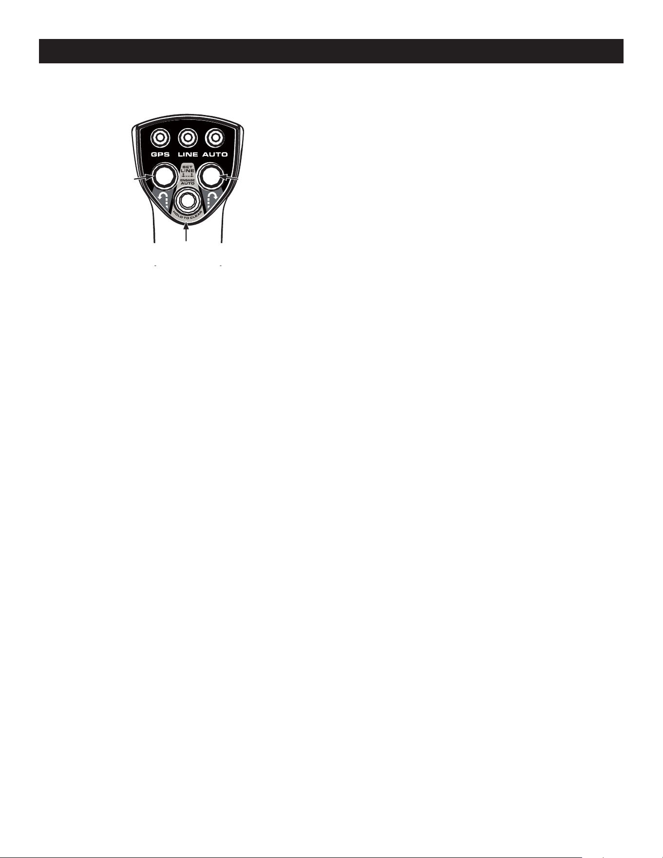
60
OPERACIÓN
AE. PANEL DE CONTROL DEL OPERADOR (SISTEMA DE
CONDUCCIÓN AUTOMÁTICA SUREPATH)
GPS - Los indicadores de color verde parpadearán en el Módulo de luces y en el
indicador GPS del Panel de Control del Operador mientras el GPM está buscando
activamente una señal y al obtener la señal se pondrán fijos en color verde.
LÍNEA - Inicialmente el indicador LÍNEA estará apagado. El indicador LÍNEA
parpadeará con luz verde cuando se haya fijado el primer punto (A) y se pondrá fijo
en color verde una vez que se haya establecido el segundo punto (B).
¡IMPORTANTE! El operador debe conducir al menos 10 yardas (30 pies) entre la
fijación del punto A y el punto B.
AUTO - El indicador AUTO estará fijo en color verde cuando la cortadora de césped
esté en modo automático y parpadeará lentamente cuando la cortadora esté en
modo manual con modo automático disponible (los puntos A y B se han establecido
y la señal del GPS es buena). El indicador AUTO está apagado cuando la cortadora de
césped no está lista para el modo automático.
NOTA: el indicador AUTO únicamente parpadeará después de anular el modo
automático girando el volante levemente a la derecha o izquierda o si el sistema
pierde la señal del GPS. Los puntos A y B permanecen establecidos.
BOTÓN DE GIRO A LA IZQUIERDA - La cortadora de césped realizará un giro de
radio cero automático a la izquierda mientras está en Modo de Conducción
Automática SurePath.
BOTÓN DE GIRO A LA DERECHA - La cortadora de césped realizará un giro de radio cero
automático a la derecha mientras está en Modo de Conducción Automática SurePath.
BOTÓN ESTABLECER LÍNEA/ACTIVAR AUTO - Establece los puntos de inicio (A) y
finalización (B) para un corte automático. Este botón también se usa para reanudar el
modo automático (presionar una vez después que el sistema está desactivado).
NOTA: el botón ESTABLECER LÍNEA/ACTIVAR AUTO también sirve como botón de
restablecimiento para borrar la línea establecida. Consulte más información en
Borrado de la línea de corte (modo de Conducción Automática SurePath) más
adelante en esta sección.
ANTES DE HACER FUNCIONAR SU CORTADORA DE CÉSPED
1. Antes de hacer funcionar la cortadora de césped, lea este manual con atención
para familiarizarse con el funcionamiento de todos los instrumentos y
controles. El manual fue preparado para ayudarlo a hacer funcionar y mantener
su máquina eficientemente.
Botón ESTABLECER
LÍNEA/ACTIVAR AUTO
Botón de
giro a la
izquierda
Botón de
giro a la
derecha
2. Llene el depósito de combustible únicamente con gasolina sin plomo limpia
y fresca, en un surtidor que indique un octanaje igual a 87 o más. Cuando el
combustible esté 1/2” por debajo de la base del cuello de llenado, deténgase.
NO LLENE EL DEPÓSITO EN EXCESO. Debe quedar espacio para la expansión de
la gasolina.
3. Nunca utilice gasolina con un contenido de más del 10% de etanol o metanol.
4. Compruebe el nivel de aceite del motor como se indica en el Manual del
operador del motor.
5. Verifique el nivel de aceite de la transmisión. El depósito de expansión del
aceite de la transmisión se encuentra debajo del asiento del operador. Siempre
limpie el área alrededor del cuello de llenado del depósito antes de verificar el
nivel de aceite para evitar que el aceite se contamine. Quite el tapón y verifique
que el nivel de aceite esté 1/4” por encima de la base del depósito. Si el nivel de
aceite está bajo, recargue con Castrol™ (Syntec®) Edge™.
6. Controle la presión de inflado de los neumáticos. 10-12 psi para los neumáticos
traseros, 20-25 psi para los neumáticos delanteros.
NOTA: los neumáticos nuevos se inflan de forma excesiva para que el reborde
se asiente bien en la llanta.
7. Verifique que todas las tuercas, pernos y tornillos estén bien apretados.
8. Verifique la tensión de las correas de transmisión de la plataforma.
a. Extraiga la cubierta de la plataforma.
b. La tensión de las correas de transmisión de la plataforma se mantiene
mediante un mecanismo de resorte que se ajusta para corregir desgaste
y estiramiento.
c. Examine las correas para detectar si están cortadas, raídas y
excesivamente desgastadas. Reemplácelas si se detecta alguno de
estos problemas.
d. Vuelva a colocar la cubierta de la plataforma.
9. Verifique que la plataforma esté nivelada. Cuando se encuentra correctamente
ajustada, la plataforma de la cortadora de césped debe estar nivelada de lado
a lado, y la parte delantera de la plataforma debe estar aproximadamente
1/4” por debajo de la parte trasera de la plataforma. Si hace falta nivelar la
plataforma, consulte la sección Cuidado del producto.
10. Lubrique todos los puntos de pivote que se indican en la sección Cuidado
del producto.
11. Ajuste el asiento para la mayor comodidad del operador, para una adecuada
visibilidad y para mantener el control completo de la máquina. Consulte la
sección Operación para ver instrucciones sobre el ajuste del asiento.
SISTEMA DE ENCLAVAMIENTO DE SEGURIDAD
Esta máquina está equipada con un sistema de enclavamiento de seguridad para
protección del operador. Si el sistema de enclavamiento alguna vez funciona
mal, no se debe hacer funcionar la máquina. Comuníquese con un distribuidor de
servicio autorizado.
• El sistema de enclavamiento de seguridad evita que el motor arranque o se
encienda a menos que los pedales de control de velocidad estén en la posición
neutral, el freno de mano esté activado y la perilla de la PTO esté desactivada.
• Para evitar un movimiento brusco al sacar el freno de mano, el sistema de
enclavamiento de seguridad apaga el motor si los pedales de control de
velocidad se mueven a una posición distinta de la neutral cuando está activado
el freno de mano.

61
OPERACIÓN
NOTA: si ambos depósitos están funcionando, y uno de ellos está vacío, el
motor no arrancará. Asegúrese de que ambos depósitos tengan combustible o
que la válvula del depósito vacío esté cerrada.
2. El operador debe estar sentado en el asiento de la cortadora con ambos pedales
de control de la transmisión en posición neutral/de arranque.
3. Aplique el freno de mano.
4. Verifique que la PTO se encuentra en la posición desconectada (abajo).
5. Levante la perilla del cebador (si se incluye) a la posición ON.
NOTA: si el motor está caliente, tal vez no sea necesario cebar el motor.
NOTA: algunas cortadoras de césped están equipadas con motores EFI
(inyección electrónica de combustible) y no vienen con cebador.
6. Mueva el control del acelerador a distancia media entre las posiciones de
velocidad LENTA y RÁPIDA .
7. Gire la llave de encendido hacia la derecha a la posición START (arranque)
y suéltela en cuanto arranque el motor; sin embargo, no dé arranque
continuamente durante más de 10 segundos por vez. Si el motor no arranca en
este período, gire la llave a la posición OFF (apagado) y espere por lo menos 30
segundos para dejar que se enfríe el motor del arrancador del motor. Inténtelo
de nuevo después de esperar. Si después de unos cuantos intentos el motor no
arranca, no siga intentando arrancarlo con el cebador cerrado ya que de esa
manera se ahogará el motor y el arranque será más difícil aún.
8. Una vez que el motor arranque, empuje el cebador (si lo tiene) hasta la mitad y
a medida que el motor se calienta, empuje el cebador hasta el fondo.
Motores con Acelerador Electrónico (Regulador electrónico)/EFI
(inyección electrónica de combustible)
1. Abra la(s) válvula(s) de combustible.
NOTA: para cebar un sistema de combustible seco, gire el interruptor de
encendido a la posición ON durante un minuto. Deje que la bomba de
combustible haga un ciclo y cebe el sistema. Gire el interruptor de encendido a
la posición OFF (Apagada).
NOTA: si ambos depósitos están funcionando, y uno de ellos está vacío, el
motor no arrancará. Asegúrese de que ambos depósitos tengan combustible o
que la válvula del depósito vacío esté cerrada.
2. El operador debe estar sentado en el asiento de la cortadora con ambos pedales
de control de la transmisión en posición neutral/de arranque.
3. Aplique el freno de mano.
4. Verifique que la PTO se encuentra en la posición desconectada (abajo).
5. Coloque la palanca del acelerador electrónico en la posición START (arranque).
6. Gire la llave de encendido hacia la derecha a la posición START (arranque)
y suéltela en cuanto arranque el motor; sin embargo, no dé arranque
continuamente durante más de 10 segundos por vez. Si el motor no arranca en
este período, gire la llave a la posición OFF (apagado) y espere por lo menos 60
segundos para dejar que se enfríe el motor del arrancador. Inténtelo de nuevo
después de esperar.
NOTA: la omisión de no respetar estos lineamientos podría quemar el motor
del arrancador.
NOTA: tras encenderlo, podría escucharse un tictac metálico. Deje funcionar
el motor durante 5 minutos. Si el ruido continúa, haga funcionar el motor
en la posición de encendido durante 20 minutos. Si el ruido persiste, lleve la
cortadora de césped a su distribuidor de servicio autorizado.
• Si el operador abandona su asiento antes de colocar el freno de mano, el
sistema de enclavamiento de seguridad apaga el motor.
• Si el operador abandona su asiento estando activada la perilla de la PTO, se
encuentre o no colocado el freno de mano, el sistema de enclavamiento de
seguridad apaga el motor.
NOTA: la perilla de la PTO debe estar desactivada para volver a encender
el motor.
Funcionamiento de práctica (uso inicial)
Operar una cortadora de césped con giro de radio cero no es lo mismo que operar una
cortadora convencional. Si bien y precisamente porque una cortadora con giro de
radio cero es más maniobrable, es necesario practicar para acostumbrarse a operar
los pedales de control de velocidad y el volante.
Se recomienda enfáticamente que encuentre un “área de práctica” de superficie
razonable, nivelada y abierta, en la cual no haya obstrucciones, peatones ni animales.
Debe practicar la operación de la cortadora de césped durante por lo menos
30 minutos.
Lleve (o haga que alguien lleve) la cortadora con cuidado al área de práctica. Cuando
esté practicando, la perilla de la PTO no debe estar activada. Mientras practica, haga
funcionar la cortadora a aproximadamente 1/2-3/4 de aceleración y a menos de la
velocidad máxima tanto en marcha adelante como en marcha atrás.
Siempre use ropa adecuada y equipos de protección personal (p.ej., anteojos de
seguridad, pantalones largos, guantes, protección auditiva, calzado de seguridad,
casco) cuando esté operando o manteniendo esta máquina. Respete todos
los lineamientos federales, estatales y locales relativos al uso de equipos de
protección personal.
ADVERTENCIA
Se necesita protección auditiva para toda exposición del operador que
supere las dos (2) horas.
Practique con cuidado maniobrar la cortadora de césped, observando las
instrucciones que figuran en la sección Conducción de la cortadora de césped.
Practique hasta que sienta que puede hacer funcionar la cortadora con seguridad.
ENCENDIDO DEL MOTOR
Para motores con acelerador/cebador o acelerador/EFI automáticos, proceda con lo
que sigue; para motores con acelerador electrónico/EFI, vaya a la sección Motores
con Acelerador Electrónico (Regulador electrónico)/EFI (inyección electrónica
de combustible).
Motores con Acelerador/Cebador Manual o Acelerador/EFI
(inyección electrónica de combustible) automática
ADVERTENCIA
Esta unidad está equipada con un sistema de enclavamiento de seguridad
para protección del operador. No haga funcionar la máquina si alguna
parte del sistema de enclavamiento funciona mal. Controle periódicamente
las funciones del sistema de enclavamiento para verificar que
funcionen adecuadamente.
ADVERTENCIA
Por razones de seguridad personal, el operador debe estar sentado en el
asiento de la cortadora al arrancar el motor.
1. Abra la(s) válvula(s) de combustible.
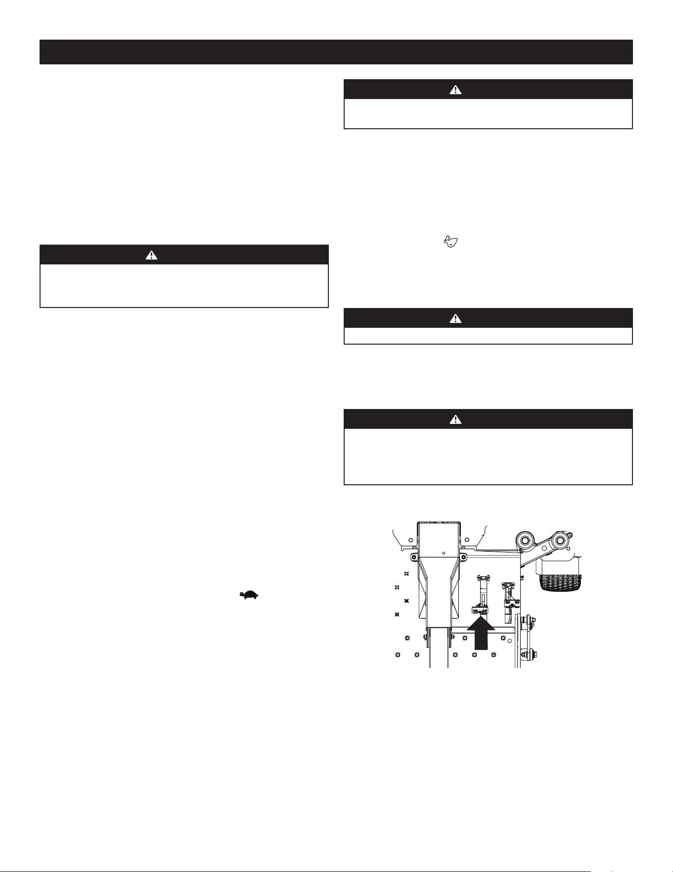
62
OPERACIÓN
ADVERTENCIA
Evite los arranques súbitos, los excesos de velocidad y las
detenciones intempestivas.
3. Ajuste el asiento del operador en la posición más cómoda que le permita operar
los controles. Consulte la sección Operación para ver instrucciones sobre el
ajuste del asiento.
4. Ajuste la inclinación del volante con la palanca de ajuste de la columna
de dirección.
5. Suelte el freno de mano.
6. Mueva la palanca de control del acelerador (si se incluye) hacia adelante a la
posición FAST (RÁPIDA) .
NOTA: si bien el motor de la cortadora de césped se ha diseñado para funcionar
a máxima aceleración, cuando practique el funcionamiento de la cortadora
debe hacerlo a menos de la aceleración máxima. Esto se aplica únicamente
durante la práctica.
ADVERTENCIA
Siempre sujete firmemente el volante.
7. Para conducir la cortadora de césped, tome el volante con firmeza con
ambas manos derecha e izquierda y continúe con Conducción de la cortadora
hacia adelante.
Conducción de la cortadora hacia adelante
ADVERTENCIA
Todos los movimientos de los pedales de conducción deben ser lentos y
suaves. El movimiento abrupto de los pedales puede afectar la estabilidad
de la cortadora y podría hacer que la misma vuelque, con el resultado de
lesiones graves o incluso la muerte del operador.
1. Presione lentamente el pedal de marcha adelante. La cortadora de césped
comenzará a desplazarse hacia adelante. Consulte la Figura 23.
Figura 23
2. A medida que el pedal de marcha adelante se presiona con más fuerza,
aumenta la velocidad de la cortadora.
3. Para reducir la velocidad de la cortadora de césped, suelte lentamente el pedal
de marcha adelante para lograr la velocidad deseada, o deje que el pedal vuelva
a la posición neutral para detener la cortadora.
Arranque del Motor en Clima Frío
Al encender el motor a temperaturas cercanas o inferiores al punto de
congelamiento, asegúrese de que se use aceite de motor de viscosidad correcta y que
la batería tenga carga completa. Arranque el motor de la siguiente forma:
1. Asegúrese de que la batería se encuentre en buen estado. Una batería caliente
tiene una capacidad de arranque mucho mayor que una batería fría.
2. Use combustible fresco para uso invernal. La gasolina para uso invernal tiene
mayor volatilidad a los efectos de mejorar el arranque. No use gasolina que le
haya quedado del verano.
3. Siga las instrucciones previas para Encendido del Motor.
Uso de Cables de Arranque para Encender el Motor
ADVERTENCIA
Las baterías contienen ácido sulfúrico y producen gases explosivos.
Asegúrese de que el área esté bien ventilada, use guantes y protectores de
ojos y evite chispas o llamas cerca de la batería.
Si la carga de la batería no es suficiente para dar arranque al motor, vuelva a cargar
la batería. Si no dispone de un cargador de batería y debe arrancar la cortadora de
césped, necesitará usar una batería de urgencia. Conecte la batería de urgencia de la
siguiente forma:
1. Conecte el extremo de un cable al borne positivo de la batería que no funciona;
luego conecte el otro extremo de ese cable al borne positivo de la batería
de urgencia.
2. Conecte un extremo del otro cable al borne negativo de la batería de urgencia;
luego conecte el otro extremo de ese cable al marco de la cortadora de césped
que no funciona, a la mayor distancia posible de la batería.
3. Arranque la cortadora de césped que no funciona según las instrucciones de
arranque normales indicadas más arriba; luego desconecte los cables de puente
en orden exactamente inverso al de la conexión.
4. Haga controlar y reparar el sistema eléctrico de la cortadora de césped lo más
pronto que fuere posible, para eliminar la necesidad de usar cables de puente
para arrancarla.
Detención del Motor
1. Coloque el interruptor de la PTO en la posición desactivada.
2. Aplique el freno de mano.
3. Mueva el acelerador a la posición de velocidad LENTA y deje que el motor
funcione en ralentí durante aproximadamente un minuto.
4. Gire la llave de encendido a la posición “OFF” (apagado) y quite la llave del
interruptor de encendido.
NOTA: siempre quite la llave del interruptor de encendido para evitar
el arranque accidental o la descarga de la batería si el equipo queda
sin supervisión.
5. Cierre la(s) válvula(s) de paso de combustible.
CONDUCCIÓN DE LA CORTADORA DE CÉSPED
1. Asegúrese que en el área no haya animales ni transeúntes,
especialmente niños.
2. Registre el área donde se usará el equipo para verificar que no haya residuos,
ramas, piedras, cables, huesos y otros objetos extraños que pudiesen lastimar a
transeúntes, o dañar la máquina o instalaciones cercanas.
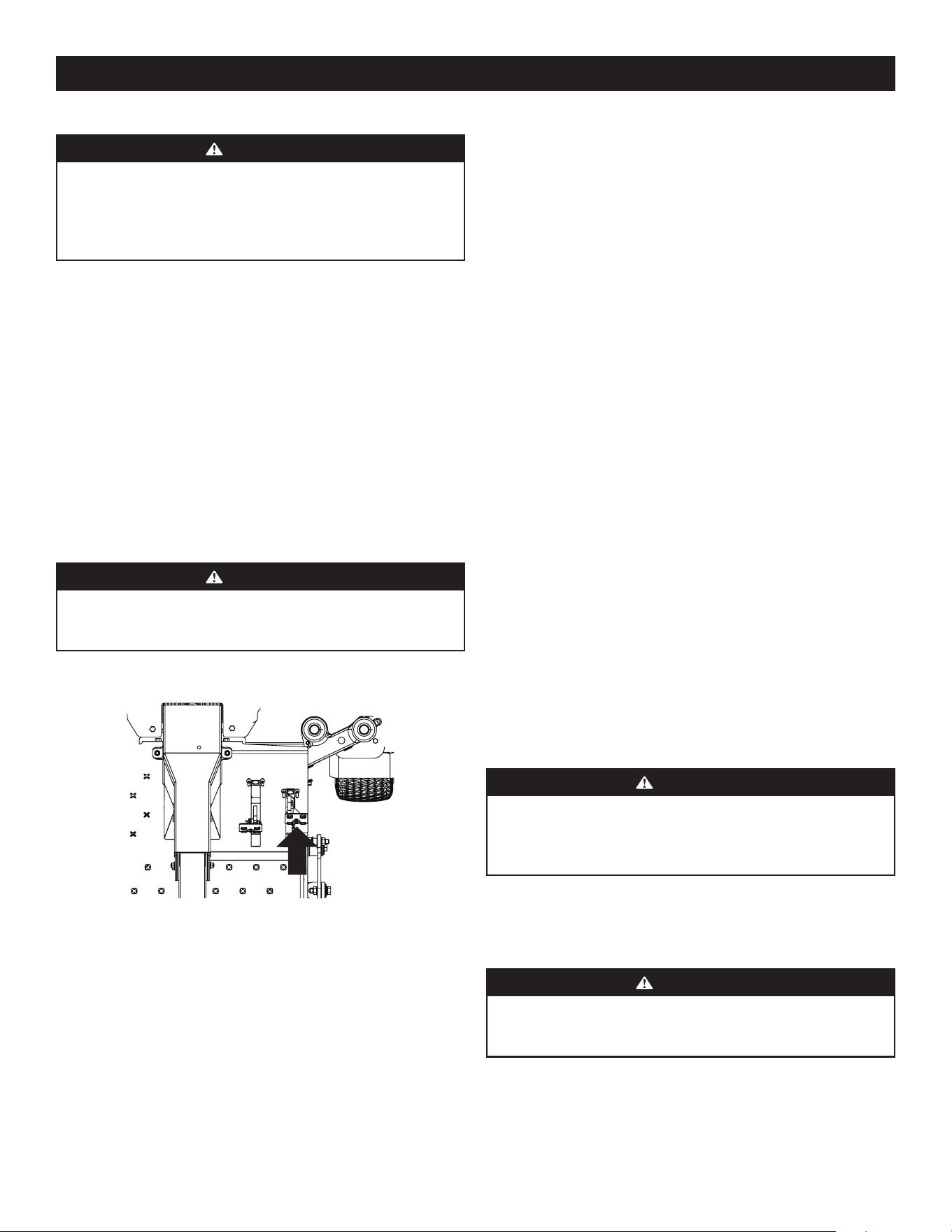
63
OPERACIÓN
Giro con la cortadora desplazándose hacia adelante
ADVERTENCIA
Al invertir la dirección del recorrido, le recomendamos que en lo posible
realice giros graduales en “U”. Los giros más agudos aumentan la posibilidad
de que se deteriore el césped y podrían afectar el control de la cortadora
de césped. Desacelere SIEMPRE la cortadora de césped antes de hacer
curvas cerradas.
Para hacer un giro con la cortadora mientras se está conduciendo hacia adelante, gire
el volante en la dirección que desea.
1. Para girar a la izquierda, gire el volante en el sentido contrario de las agujas del
reloj (hacia la izquierda del operador).
2. Para girar a la derecha, gire el volante en el sentido de las agujas del reloj (hacia
la derecha del operador).
3. Cuanto más distancia se gire el volante, más cerrado será el giro de la cortadora.
4. Para realizar un “giro de pivote” mueva el volante de modo que la rueda
interna quede angulada a aproximadamente 88° y el neumático lateral de giro
no rotará.
NOTA: los “giros de pivote” sobre el pasto aumentan significativamente el
potencial de que se deteriore el césped así como la posibilidad de daños a la
superficie de tracción y al neumático.
Conducción de la cortadora marcha atrás
ADVERTENCIA
Mire siempre hacia atrás y hacia abajo a ambos lados de la cortadora de
césped antes de desplazarse hacia atrás. Siempre mire hacia atrás cuando se
desplace en marcha atrás.
1. Presione lentamente el pedal de marcha atrás. La cortadora de césped
comenzará a desplazarse hacia atrás. Consulte la Figura 24.
Figura 24
2. A medida que el pedal de marcha atrás se presiona con más fuerza, aumenta la
velocidad de la cortadora.
3. Para reducir la velocidad de la cortadora de césped, suelte lentamente el pedal
de marcha atrás para lograr la velocidad deseada, o deje que el pedal vuelva a
la posición neutral para detener la cortadora.
Giro con la cortadora desplazándose hacia atrás
Para hacer un giro con la cortadora mientras se está conduciendo marcha atrás, gire
el volante en la dirección que desea.
1. Para girar a la izquierda mientras conduce marcha atrás, gire el volante en el
sentido de las agujas del reloj (hacia la derecha del operador).
2. Para girar a la derecha mientras conduce marcha atrás, gire el volante en el
sentido contrario a las agujas del reloj (hacia la izquierda del operador).
3. Cuanto más distancia se gire el volante, más cerrado será el giro de la cortadora.
4. Para realizar un “giro de pivote” mueva el volante de modo que la rueda
interna quede angulada a aproximadamente 88° y el neumático lateral de giro
no rotará.
NOTA: los “giros de pivote” sobre el pasto aumentan significativamente el
potencial de que se deteriore el césped así como la posibilidad de daños a la
superficie de tracción y al neumático.
Giro de radio cero
1. Una maniobra de giro de radio cero se puede realizar mientras la máquina
se está desplazando en marcha adelante o atrás si el volante está girado
completamente en una de esas direcciones.
2. Para girar en el sentido de las agujas del reloj mientras se está desplazando en
marcha adelante, gire el volante en el sentido de las agujas del reloj y presione
el pedal de marcha adelante. Suelte el pedal y la máquina dejará de girar. Si
está presionado el pedal de marcha atrás, el giro será en el sentido contrario a
las agujas del reloj.
3. Para girar en el sentido contrario a las agujas del reloj mientras se está
desplazando en marcha adelante, gire el volante en el sentido contrario a las
agujas del reloj y presione el pedal de marcha adelante. Suelte el pedal y la
máquina dejará de girar. Si está presionado el pedal de marcha atrás, el giro
será en el sentido de las agujas del reloj.
Detención de la Cortadora de Césped
1. Deje que los pedales de marcha adelante y atrás regresen a la posición neutral
para detener el movimiento de la cortadora.
2. Oprima la perilla de la PTO hacia abajo a la posición desactivada.
3. Use el pedal de elevación de la plataforma para levantar la misma a su posición
más alta.
4. Si está desmontando la máquina, deje que los pedales regresen a la posición
neutral, aplique el freno de mano, gire el interruptor de encendido a la posición
OFF y extraiga la llave del interruptor.
ADVERTENCIA
Nunca deje el asiento de la cortadora sin antes desactivar la PTO, sin antes
mover los pedales a la posición neutral y sin antes aplicar el freno de mano.
Si deja la cortadora sin vigilancia, debe girar la llave de encendido a la
posición OFF y extraerla.
Conducción en pendientes
Consulte la información sobre el indicador de pendiente en la sección Prácticas de
operación seguras para determinar en qué pendientes podría no operar la cortadora
de manera segura.
ADVERTENCIA
No use la cortadora de césped en pendientes con una inclinación mayor a
20°/35% (una elevación aproximada de 4 pies por cada 10 pies). La unidad
podría volcar y causar lesiones graves.
1. Siempre conduzca el tractor de forma transversal a la pendiente, nunca hacia
arriba y hacia abajo.
2. En lo posible evite girar cuesta abajo. Comience en la base de la pendiente y
opere cuesta arriba. Siempre reduzca la velocidad antes de dar la vuelta.
3. Ponga especial cuidado y conduzca lentamente al girar cuesta abajo.
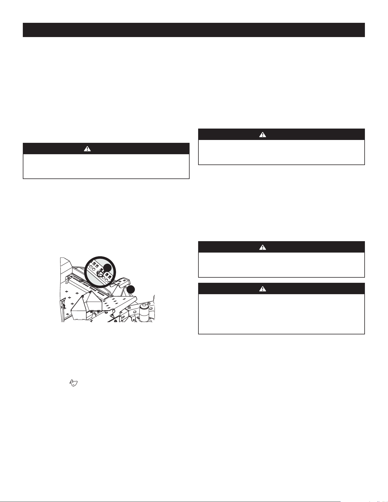
64
OPERACIÓN
Funcionamiento de la perilla de la PTO
Maneje la perilla de la PTO de la siguiente manera:
1. Mueva la palanca de control del acelerador (si se incluye) aproximadamente a la
posición de aceleración intermedia.
2. Tire de la perilla de la PTO hacia arriba a la posición ACTIVADA.
3. Adelante la palanca del acelerador hasta la velocidad operativa (velocidad
máxima del motor).
4. El operador debe permanecer en el asiento de la cortadora de césped en todo
momento. Si el operador debe abandonar el asiento sin apagar el interruptor de
la toma de fuerza, se apagará el motor de la cortadora.
Uso de la plataforma de corte
ADVERTENCIA
Asegúrese que el área donde se va a cortar esté libre de desechos,
ramitas, piedras, cables u otros objetos que puedan ser arrojados por las
cuchillas rotativas.
NOTA: no accione la plataforma de la cortadora cuando esté apoyada sobre el
césped. Se produce el desgaste prematuro y la posible falla de la correa en “V”
y del embrague de la PTO. Antes de enganchar la plataforma de corte, levante
totalmente la plataforma o lleve la máquina a un área donde no haya césped.
1. Con el pedal de elevación de la plataforma (a) suba la plataforma hasta su
posición más alta, coloque el pasador de horquilla (b) adosado a la cortadora
en el orificio deseado sobre el posicionamiento de altura de la plataforma,
luego suelte lentamente el pedal de elevación de la plataforma (a). Consulte la
Figura 25.
L
o
w
e
r
a
b
Figura 25
2. Corte de forma transversal a la pendiente, no hacia arriba ni hacia abajo. Si
corta el césped en pendiente, comience por la base y desplácese hacia arriba
para asegurar que siempre se gire cuesta arriba.
3. Al realizar la primera pasada elija un punto del lado opuesto del área a cortar.
4. Active la perilla de la PTO y mueva el control del acelerador a la posición de
velocidad RÁPIDA .
5. Quite el pasador de horquilla, suba la plataforma hasta la posición más
alta (transporte), coloque el pasador de horquilla en la posición deseada y
asegúrela con el pasador de horquilla. Baje la plataforma de corte al valor de
altura deseado.
6. Empuje el pedal de marcha adelante lentamente hacia adelante para que la
cortadora de césped avance hacia adelante, y mantenga la cortadora orientada
directamente hacia el punto de alineación.
NOTA: la velocidad de la cortadora de césped afecta la calidad del corte que
realiza. Cortar a máxima velocidad afectará negativamente la calidad del corte.
Controle la velocidad absoluta con los pedales de marcha.
7. Cuando se acerque al otro extremo de la franja, reduzca la velocidad o
deténgase antes de girar. Se recomienda realizar un giro en U a menos que sea
necesario realizar un giro de radio cero.
8. Alinee la cortadora de césped con un borde de la franja cortada y superponga la
pasada aproximadamente 3 pulgadas.
9. Oriente la cortadora en cada franja subsiguiente de modo que se alinee con la
franja ya cortada.
10. Para evitar la formación de surcos o ranuras en el césped, en lo posible
varíe la dirección de las franjas de corte aproximadamente 45° en cada
corte subsiguiente.
ADVERTENCIA
Tenga sumo cuidado al atravesar senderos de grava o caminos de acceso.
Desactive la perilla de la PTO y suba la plataforma hasta la posición más alta/
de transporte antes de cruzar.
NOTA: cuando detenga la cortadora por algún motivo mientras se encuentra en
un área de césped, haga siempre lo siguiente:
a. Compruebe que los pedales de marcha se encuentran en punto muerto.
b. Aplique el freno de mano.
c. Apague el motor y retire la llave.
d. Eso reducirá al mínimo la posibilidad de “quemar” el césped con el escape
caliente del motor en funcionamiento de la cortadora de césped.
SISTEMA DE CONDUCCIÓN AUTOMÁTICA SUREPATH
ADVERTENCIA
Asegúrese que el área donde se va a cortar esté libre de desechos,
ramitas, piedras, cables u otros objetos que puedan ser arrojados por las
cuchillas rotativas.
ADVERTENCIA
El sistema de Conducción Automática SurePath no detecta objetos ni
obstrucciones que puedan estar en el camino de la plataforma de corte o de
la máquina. Siempre opere la máquina con cuidado y atención. Detenga la
máquina de inmediato o condúzcala manualmente alrededor de obstáculos
antes de reanudar el modo de Conducción Automática SurePath.
El sistema de Conducción Automática SurePath usa tecnología de GPS para
controlar semi-autónomamente las funciones de dirección y giro para lograr franjas
consistentes, reducir la cobertura con césped y maximizar la eficiencia del corte.
Inicialización del modo de Conducción Automática SurePath
1. Encienda la cortadora de césped. Vea las instrucciones que figuran en la sección
Encendido del Motor.
2. Las luces indicadoras/de advertencia parpadearán en azul mientras se está
inicializando el sistema de Conducción Automática SurePath.
3. Una vez iniciado el sistema, las luces indicadoras/de advertencia empezarán
a parpadear en verde. El sistema de Conducción Automática SurePath está
buscando activamente la señal del GPS.
¡IMPORTANTE! La máquina debe estar en el exterior, lejos de árboles grandes
y edificios para poder recibir la señal.
NOTA: la recepción de la señal tarda aproximadamente 90 segundos.
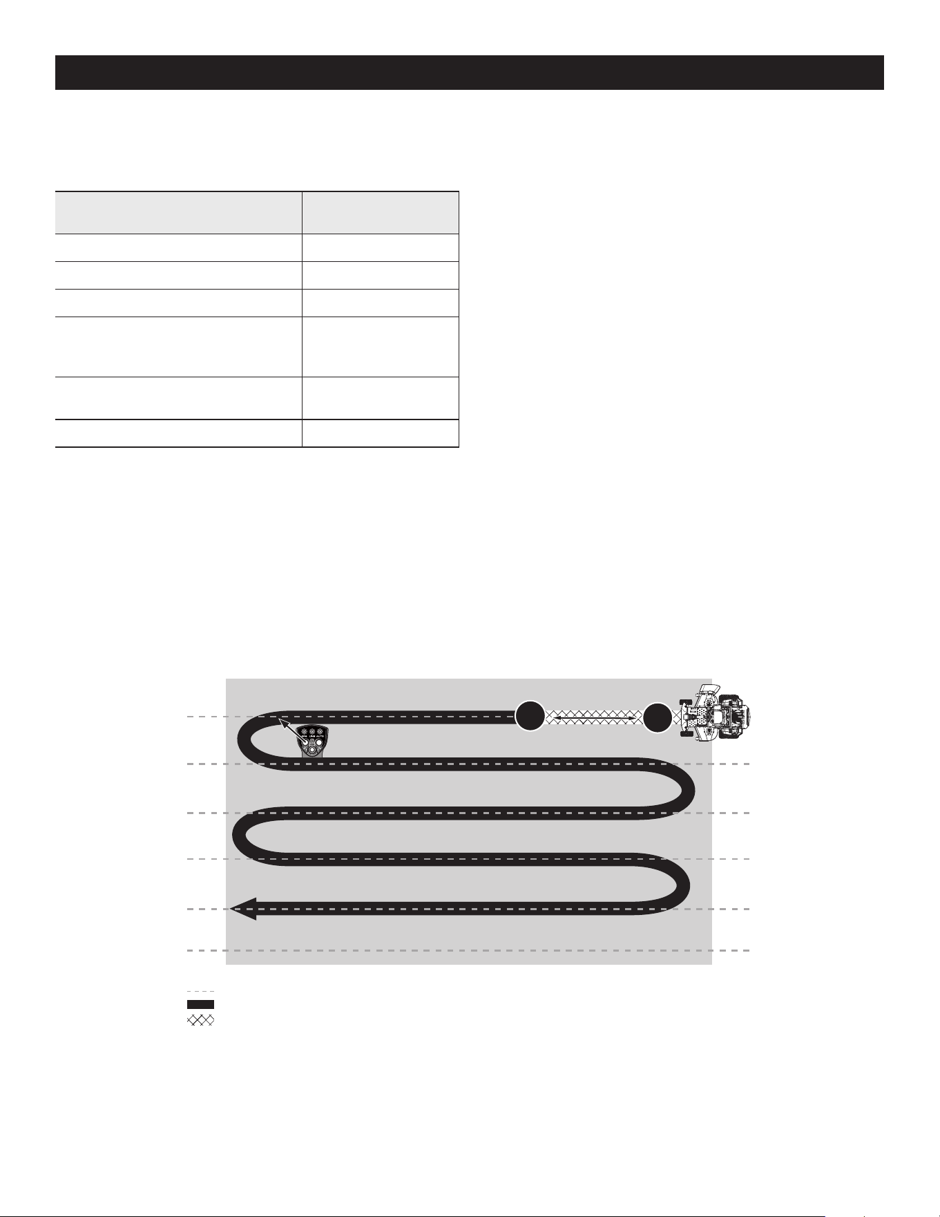
65
OPERACIÓN
4. Una vez recibida, las luces indicadoras/de advertencia se pondrán fijas en verde.
La cortadora de césped ya está lista para el modo de Conducción Automática
SurePath. Consulte la lista de colores y descripciones de las luces indicadoras/de
advertencia en la Figura 26.
Descripciones
Colores de las luces
indicadoras/de advertencia
Inicialización del sistema Azul parpadeante
Intentando obtener señal Verde parpadeante
†
Señal recibida Verde fija
Velocidad demasiado rápida de la cortadora
para el modo de dirección automática de
SurePath
Amarillo parpadeante
*
Sujetar volante para anular el modo de
Conducción Automática SurePath
Rojo parpadeante
Actualización de software en proceso Amarillo sólido
#
*
También indica una presión de botón ignorada por el sistema
†
El parpadeo rojo periódico indica que no hay conectividad celular
#
Consulte al distribuidor autorizado para obtener más información
Figura 26
Establecimiento de la línea de corte (modo de Conducción
Automática SurePath)
1. Encienda la cortadora de césped. Vea las instrucciones que figuran en la sección
Encendido del Motor.
NOTA: para establecer la línea de corte no es necesario que la PTO esté activada.
2. Una vez que las luces indicadoras/de advertencia se ponen fijas en verde, el
sistema está listo para el modo de Conducción Automática SurePath.
3. Establezca su línea de corte siguiendo estos pasos:
• Determine la ubicación de la primera pasada, escogiendo un punto del lado
opuesto al área donde cortará el césped.
• Conduzca en línea recta hacia el punto escogido en el paso anterior y
presione brevemente el botón ESTABLECER LÍNEA/ACTIVAR AUTO que está
en el Panel de Control del Operador para establecer el punto A. Consulte la
Figura 27. El indicador LÍNEA comenzará a parpadear en verde cuando se
establezca el punto A.
• Continúe conduciendo en línea recta, recorra al menos 10 yardas (30 pies),
luego vuelva a presionar brevemente el botón ESTABLECER LÍNEA/ACTIVAR
AUTO que está en el Panel de Control del Operador para establecer el punto
B. Consulte la Figura 27. Los indicadores LÍNEA y AUTO se pondrán fijos en
color verde cuando se hayan establecidos los puntos A y B.
NOTA: una vez que el indicador AUTO que está en el panel de Control del
Operador se pone fijo en verde, el sistema está activado para el modo de
Conducción Automática SurePath y el operador debe soltar el volante.
¡IMPORTANTE! Cuando se establece la línea de corte, la cortadora pasa
automáticamente al modo de Conducción Automática SurePath.
B*
A*
*
Giro a la izquierda (como se
muestra) o giro a la derecha*
Líneas establecidas infinitas de dirección automática SurePath
Corte con dirección automática SurePath
Corte manual
Pulse y suelte
>10 yd (30 pi)
Figura 27
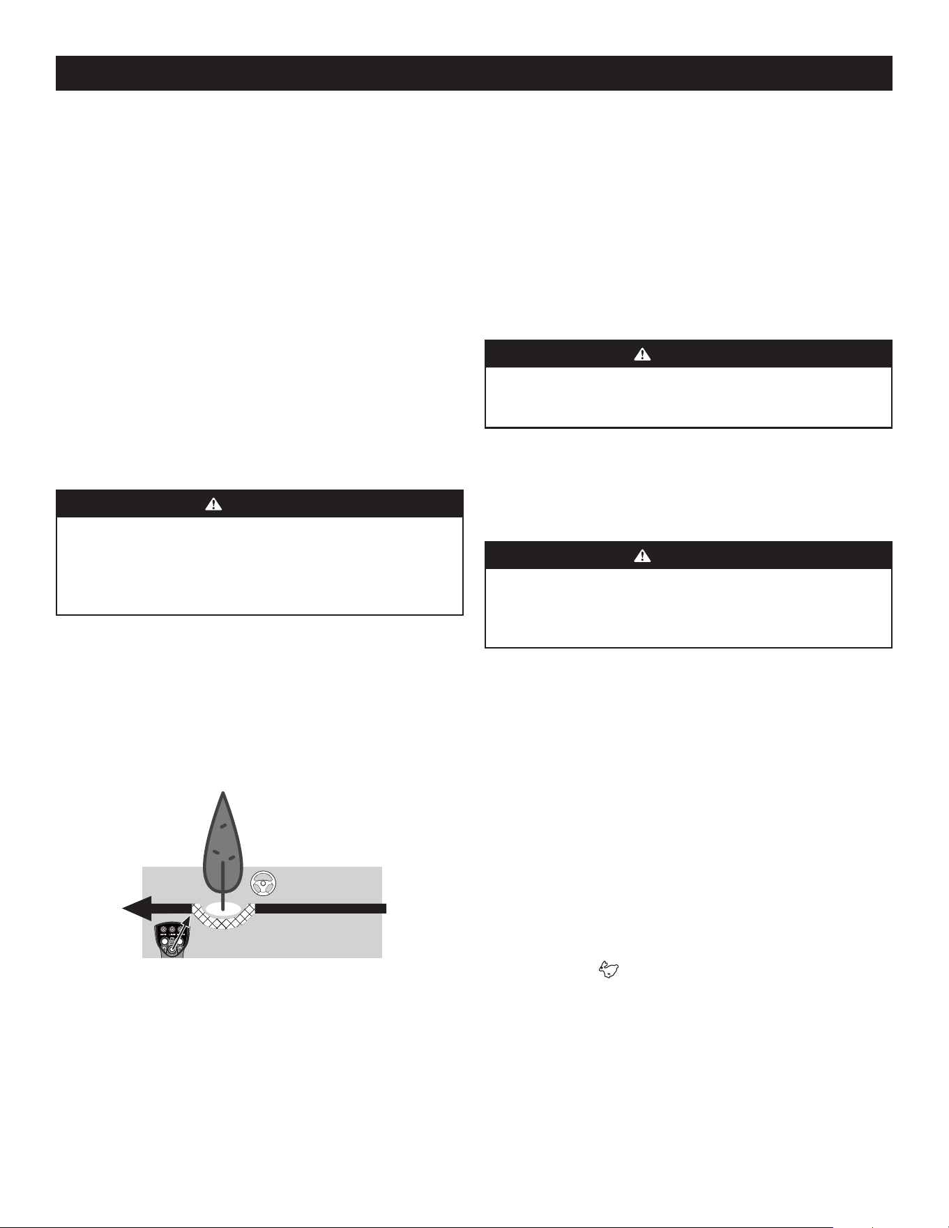
66
OPERACIÓN
Apagado automático o pérdida de la señal del GPM
Si el GPM pierde señal, la cortadora regresará al modo manual. Se producirá la
siguiente secuencia:
1. Las luces indicadoras/de advertencia del Módulo Luces parpadearán en rojo y el
sistema dejará de conducir la cortadora de césped.
2. El operador debe retomar el control del volante y girarlo levemente hacia la
derecha o izquierda para regresar al modo manual.
3. Una vez que se ha recuperado la señal del GPS, las luces indicadoras/
de advertencia se pondrán fijas en verde. Presione brevemente el botón
ESTABLECER LÍNEA/ACTIVAR AUTO para reanudar el modo de Conducción
Automática SurePath.
ADVERTENCIA
Si el sistema de Conducción Automática SurePath sufre algún desperfecto,
deje de usar la máquina o desactive el sistema y hágalo reparar por un
distribuidor de servicio autorizado lo antes posible.
NOTA: si el sistema de Conducción Automática SurePath sufre algún desperfecto,
consulte Solución de Problemas en la sección Cuidado del producto o póngase en
contacto con personal de servicio autorizado.
Uso de la plataforma de la cortadora de césped (modo de
Conducción Automática SurePath)
ADVERTENCIA
Para evitar lesiones personales tanto suyas como de otras personas, siempre
sea precavido y esté atento a sus alrededores cuando esté usando el modo
de Conducción Automática SurePath. Detenga la máquina de inmediato si
alguien entra en la zona.
NOTA: el operador siempre está en control de la velocidad y el frenado de
la cortadora.
1. Con el pedal de elevación de la plataforma (a) suba la plataforma hasta su
posición más alta, coloque el pasador de horquilla (b) adosado a la cortadora en
el orificio deseado sobre el posicionamiento de altura de la plataforma, luego
suelte lentamente el pedal de elevación de la plataforma (a). Consulte la Figura
25 en la página 64.
2. Corte de forma transversal a la pendiente, no hacia arriba ni hacia abajo. Si
corta el césped en pendiente, comience por la base y desplácese hacia arriba
para asegurar que siempre se gire cuesta arriba.
3. Para establecer su línea de corte, consulte la sección Establecimiento de la línea
de corte (modo de Conducción Automática SurePath).
¡IMPORTANTE! Cuando se establece la línea de corte, la cortadora pasa
automáticamente al modo de Conducción Automática SurePath.
4. Active la perilla de la PTO y mueva el control del acelerador a la posición de
velocidad RÁPIDA .
5. Para avanzar hacia adelante, empuje lentamente el pedal de marcha adelante
hacia adelante. El sistema de Conducción Automática SurePath mantendrá la
cortadora alineada con la línea de corta pre-establecida.
NOTA: la velocidad de la cortadora de césped afecta la calidad del corte que
realiza. Cortar a máxima velocidad afectará negativamente la calidad del corte.
Controle la velocidad absoluta con los pedales de marcha.
Borrado de la línea de corte (modo de Conducción
Automática SurePath)
Para restablecer el sistema y quitar los puntos guardados que definen la línea
de corte:
1. Detenga la cortadora.
2. Apague la PTO.
3. Mantenga presionado el botón ESTABLECER LÍNEA/ACTIVAR AUTO que está en el
Panel de Control del Operador durante al menos 3 segundos.
NOTA: si no se mantiene presionado el botón ESTABLECER LÍNEA/ACTIVAR AUTO
por al menos 3 segundos, las luces indicadoras/de advertencia parpadearán en
amarillo para indicar un restablecimiento inválido.
4. El indicador Línea que está en el Panel de Control del Operador se apagará una
vez borrados los puntos A y B.
NOTA: el Operador tendrá que restablecer los puntos A y B antes de reanudar
el modo de Conducción Automática SurePath. Consulte Establecimiento de la
línea de corte (modo de Conducción Automática SurePath).
NOTA: el borrado de la línea de corte inmediatamente regresará a la cortadora
al modo manual.
ADVERTENCIA
Si mantiene presionado el botón ESTABLECER LÍNEA/ACTIVAR AUTO por
menos de 3 segundos, la línea de corte no se restablecerá y la cortadora
podría volver al modo automático si las líneas pre-establecidas siguen
guardadas. Ello podría dar lugar a la pérdida del control, daños materiales,
lesiones personales e incluso podría provocar la muerte.
Anulación manual del modo de Conducción Automática SurePath
Para sacar la cortadora de césped del modo de Conducción Automática SurePath, el
operador debe retomar el control del volante y girarlo levemente hacia la derecha
o izquierda. Esto pondrá a la cortadora en modo manual. El indicador AUTO estará
parpadeando. Consulte la Figura 28.
Para reanudar el modo de Conducción Automática SurePath, presione brevemente
el botón ESTABLECER LÍNEA/ACTIVAR AUTO que está en el Panel de Control del
Operador. Consulte la Figura 28.
Esquive manualmente
los obstáculos
ESTABLECER LÍNEA/ CONECTAR AUTOM
para reanudar la dirección automática
Pulse brevemente el botón
Figura 28
NOTA: no tenga presionado el botón ESTABLECER LÍNEA/ACTIVAR AUTO cuando
reanude el modo de Conducción Automática SurePath. Si mantiene presionado el
botón durante 3 segundos o más el sistema se restablecerá, y se borrarán los puntos
A y B establecidos previamente.
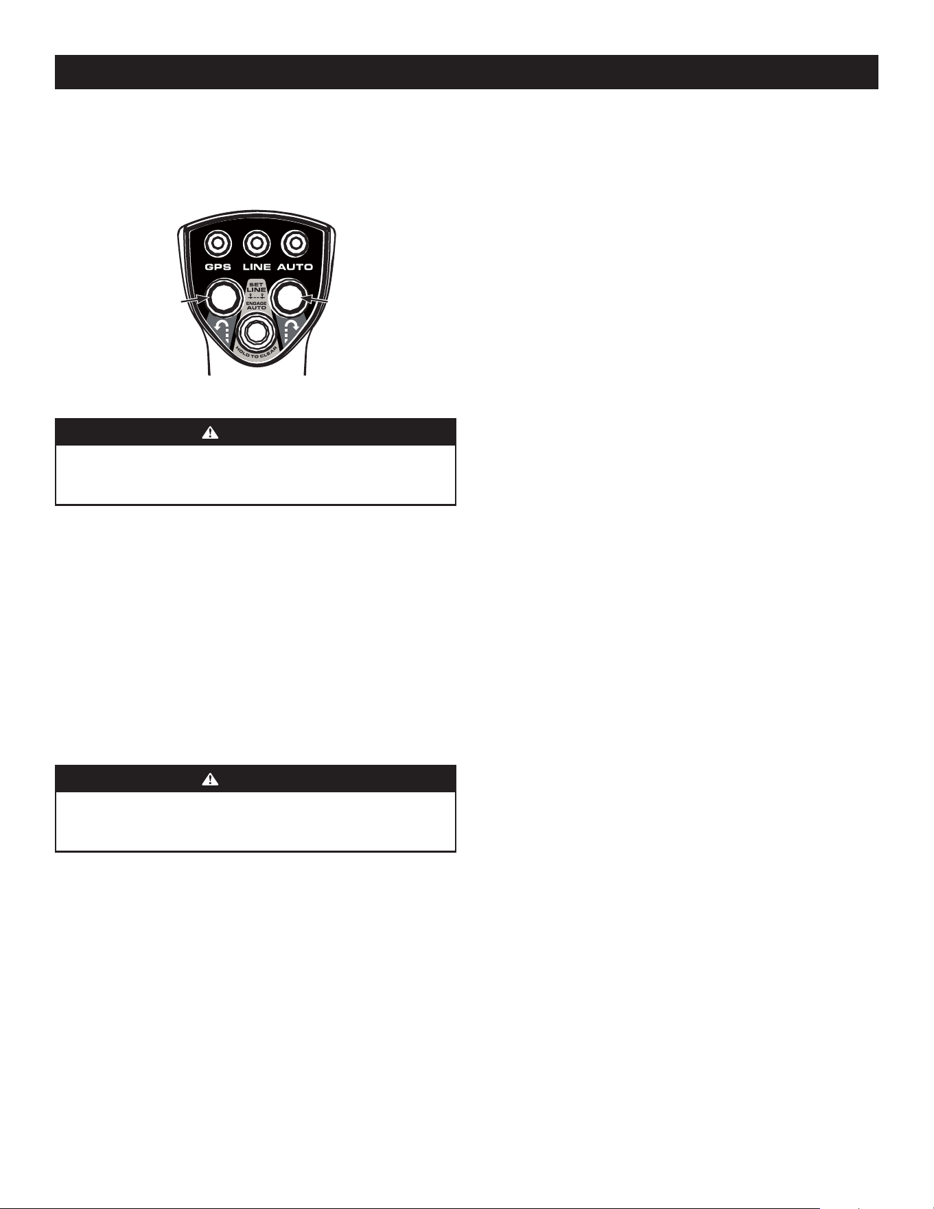
67
OPERACIÓN
6. Cuando se esté acercando al otro extremo de la franja, libere presión sobre el
pedal de marcha delantera levemente para desacelerar antes de iniciar un giro
de radio cero a la derecha o izquierda. Presione brevemente el botón de giro a
la derecha o izquierda que está en el Panel de Control del Operador. Consulte
Figura 29.
Giro de radio cero
a la izquierda
Giro de radio cero
a la derecha
Figura 29
ADVERTENCIA
No intente girar a alta velocidad cuando esté usando el modo de Conducción
Automática SurePath. El sistema hará giros menos abruptos y más precisos a
velocidades más bajas.
NOTA: los botones de giro a la derecha e izquierda únicamente funcionarán si se ha
activado el modo de Conducción Automática SurePath.
NOTA: el sistema de Conducción Automática SurePath hará giros menos abruptos
y más precisos a velocidades más bajas, y le permitirá captar más fácilmente y
mantener la señal para la siguiente línea paralela a seguir.
7. Compruebe que la cortadora esté alineada con la línea de corte antes
de acelerar.
8. Repita los pasos 5-7 para continuar cortando líneas paralelas en el modo de
Conducción Automática SurePath.
¡IMPORTANTE! Para evitar la formación de surcos o ranuras en el césped, en lo
posible varíe la dirección de las franjas de corte aproximadamente 45° en cada
corte subsiguiente.
ADVERTENCIA
Tenga sumo cuidado al atravesar senderos de grava o caminos de acceso.
Desactive la perilla de la PTO y suba la plataforma hasta la posición más alta/
de transporte antes de cruzar.
NOTA: cuando detenga la cortadora por algún motivo mientras se encuentra en
un área de césped, haga siempre lo siguiente:
a. Compruebe que los pedales de marcha se encuentran en punto muerto.
b. Aplique el freno de mano.
c. Apague el motor y retire la llave.
d. Eso reducirá al mínimo la posibilidad de “quemar” el césped con el escape
caliente del motor en funcionamiento de la cortadora de césped.
9. Libere levemente presión sobre el pedal de marcha adelante antes de iniciar un
giro de radio cero a la derecha o izquierda.
10. Compruebe que la cortadora esté alineada con la línea de corte antes
de acelerar.
Desactivación del sistema de Conducción Automática SurePath
Para evitar el uso no autorizado, o si el sistema sufre algún desperfecto, el sistema
de Conducción Automática SurePath puede desactivarse quitando el fusible del GPM
(etiquetado como F5:GPM que está en la caja de fusibles ubicada debajo del asiento
del operador).
Pasadas forzadas
El sistema de Conducción Automática SurePath forzará el corte de pasadas lado a
lado en direcciones opuestas. Esta configuración puede ajustarse contactando a un
centro de servicio autorizado.
Calibración
Consulte información sobre la calibración del sistema de Conducción Automática
SurePath en Calibración dentro de la sección Cuidado del producto.
CUCHILLAS DE CORTE DE LA CORTADORA DE CÉSPED
Las cuchillas, que normalmente se instalan en fábrica en una cortadora, ofrecen
el mejor desempeño en corte de césped en la mayoría de céspedes y condiciones
de corte; no obstante, habrá ocasiones en las que el tipo de césped, la etapa de
crecimiento del césped, las condiciones del suelo y las condiciones climáticas
requerirán diferentes tipos de cuchillas de corte. Como las plataformas de las
cortadoras están diseñadas para que el traslape de las cuchillas de corte en general
sea superior a 1.5", no hay ninguna necesidad de orientar una cuchilla de corte a otra
adyacente (esto es, las cuchillas no tienen que estar "temporizadas" ni sincronizadas).
Elevación alta - En general, estas son las mejores cuchillas de corte para la
mayoría de los céspedes y condiciones de corte. Las cuchillas de elevación alta son
cuchillas instaladas en fábrica sobre estas cortadoras de césped. Estas cuchillas
proporcionarán una "elevación" extra para los céspedes de hoja más delgada, son
aptas para céspedes lozanos y ofrecen máxima descarga de césped y desechos. Estas
cuchillas por lo general se requieren para sistemas de recolección de materiales. En
comparación con otras, estas cuchillas necesitan más caballaje, y en general generan
los niveles de ruido más altos.
Elevación intermedia - Estas cuchillas requieren menos caballaje que las de elevación
alta, y en general funcionan bien en céspedes de hoja más ancha y en algunas
aplicaciones de abono.
Elevación baja - Estas cuchillas requieren menos caballaje que las de elevación alta y
elevación intermedia, y en general donde mejor funcionan son con céspedes de hoja
ancha, céspedes de crecimiento poco denso y condiciones de suelo arenoso. Generan
los niveles de ruido más bajos. Las cuchillas de elevación baja se configuran sin
desfase, y con una cantidad máxima de borde de corte afilado.
Abono - Estas cuchillas en general se diseñan para usar en plataformas de corte
equipadas con deflectores para abono. La forma de la cuchilla en general produce
una turbulencia más alta de modo que el césped pueda ser cortado y vuelto a cortar
repetidamente en pedazos más pequeños. Estas cuchillas por lo general requieren
más caballaje que otras. Las cuchillas para abono funcionan mejor cuando el
césped se corta en el nivel máximo, se quitan longitudes mínimas de césped y las
condiciones del césped son secas en general.
NOTA: consulte una lista de números de piezas en la sección Complementos
y accesorios.

68
OPERACIÓN
CORTADORA RECONFIGURABLE
Deflector
interior
Deflector de
descarga
Cuchillas de corte
Ruedas de
calibración
Rodillo delantero Rodillos traseros
Configuración estándar Instalado Instalado Elevación alta Bajas = 3 a 5" Bajas = 3 a 5" Bajas = 3 a 5"
Vástagos (Dandelion,
Bahia, Buckhorn, etc.)
Quitado Instalado Elevación alta
Altas = 1 a 2-1⁄2”
Bajas = 3 a 5"
Altas = 1 a 2-1⁄2”
Bajas = 3 a 5"
Altas = 1 a 2-1⁄2”
Bajas = 3 a 5"
Césped muy lozano y/o alto Quitado Instalado Elevación alta
Altas = 1 a 2-1⁄2”
Bajas = 3 a 5"
Altas = 1 a 2-1⁄2”
Bajas = 3 a 5"
Altas = 1 a 2-1⁄2”
Bajas = 3 a 5"
Altura de corte baja (1 a 2") Instalado Instalado Elevación baja Altas = 1 a 2-1⁄2” Altas = 1 a 2-1⁄2” Altas = 1 a 2-1⁄2”
Abono Instalado Quitado Elevación alta/abono
Altas = 1 a 2-1⁄2”
Bajas = 3 a 5"
Altas = 1 a 2-1⁄2”
Bajas = 3 a 5"
Altas = 1 a 2-1⁄2”
Bajas = 3 a 5"
Recolección de materiales Instalado Instalado Elevación alta
Altas = 1 a 2-1⁄2”
Bajas = 3 a 5"
Altas = 1 a 2-1⁄2”
Bajas = 3 a 5"
Altas = 1 a 2-1⁄2”
Bajas = 3 a 5"
Abrasivo (arenoso), seco Quitado Instalado Elevación baja
Altas = 1 a 2-1⁄2”
Bajas = 3 a 5"
Altas = 1 a 2-1⁄2”
Bajas = 3 a 5"
Altas = 1 a 2-1⁄2”
Bajas = 3 a 5"
Húmedo Instalado Instalado Elevación alta
Altas = 1 a 2-1⁄2”
Bajas = 3 a 5"
Altas = 1 a 2-1⁄2”
Bajas = 3 a 5"
Altas = 1 a 2-1⁄2”
Bajas = 3 a 5"
Notas sobre la tabla: esta tabla es un bosquejo general de las configuraciones sugeridas; las condiciones de corte podrían variar.
Deflector interior: el deflector interior regula la descarga de césped. Quite el deflector interior para césped de volumen alto e instale el deflector interior para un corte
de precisión.
Deflector de descarga: el deflector de descarga optimiza el patrón de descarga de césped. El deflector de descarga reduce los terrones y debería quitarse para aplicación
de abono.
Cuchillas de corte: las cuchillas de corte cortan césped, elevan el césped y descargan césped a través del canal de descarga.
Ruedas de calibración: las ruedas de calibración reducen el despastaje, ayudan con el corte de precisión y reducen el deterioro del césped durante los giros.
Rodillo delantero (si está equipado): el rodillo delantero reduce el despastaje, ayuda con el corte de precisión y reduce el deterioro del césped durante los giros.
Rodillos traseros: los rodillos traseros reducen el despastaje y le dan al césped una apariencia de franjas.
NOTA: para evitar dañar el césped, no debería quitarse más de 1/3 de la altura de césped durante una misma operación de corte (p.ej., si el césped tiene 6" de altura, córtelo
hasta 4”).

69
CUIDADO DEL PRODUCTOCUIDADO DEL PRODUCTO
Antes de cada uso Cada 50 horas Cada 500 horas
Después de
cortar el césped
Verifique el nivel de gasolina
Verifique que las mangueras hidráulicas no tengan fugas
Verifique los neumáticos y la presión de los mismos
Verifique la plataforma, la cortadora de césped y las correas
de transmisión hidrostática
Verifique las cuchillas y que el perno de la cuchilla esté apretado
Verifique que los interruptores de seguridad funcionen correctamente
Verifique el nivel de líquido en el depósito de expansión del
aceite de la transmisión
Verifique/limpie los filtros de admisión y los ventiladores
de refrigeración del motor *
Verifique/limpie el colector de escape, el tubo del silenciador y los protectores
del silenciador *
Verifique/limpie la parte de arriba y de abajo de la plataforma y debajo y
alrededor de las cubiertas del husillo y del área de la correa *
Verifique/limpie alrededor de los fusibles, el cableado y los arneses de cables *
Verifique/limpie alrededor de la transmisión, los ejes y los ventiladores *
Sacuda/limpie el área de control de la bomba debajo de la bandeja de piso
Sacuda/limpie el área del control de pedales debajo del apoyapiés
Lubrique los puntos de desgaste (consulte la tabla)
Limpie las aletas de refrigeración y superficies externas del motor *
Cambie el fluido hidrostático y el filtro de los transejes †
† — Cambie el fluido hidrostático y el filtro de los transejes y el filtro de los transejes después de las primeras 300 horas
* — Realice más frecuentemente si hay mucho polvo
PROGRAMA DE MANTENIMIENTO
ADVERTENCIA
Antes de realizar cualquier tipo de mantenimiento o servicio, desactive todos
los controles y detenga el motor. Espere a que se detengan completamente
todas las piezas móviles. Desconecte los cables de las bujías y el cable negativo
de la batería para evitar un arranque involuntario. Utilice siempre anteojos de
seguridad durante el funcionamiento o mientras ajusta o repara este equipo.
Siga el programa de mantenimiento que se presenta a continuación. En esta tabla
sólo se describen pautas de servicio.
Consulte el Manual del Operador del Motor para obtener información sobre las tareas
de mantenimiento del motor que se enumeran en la tabla a continuación.

70
CUIDADO DEL PRODUCTO
NOTA: este manual del operador corresponde a varios modelos. Las características
de las cortadoras de césped pueden variar según los modelos. No todas las
características que se incluyen en este manual se aplican a todos los modelos de
cortadora de césped y la cortadora de césped que se ilustra aquí puede diferir de
la suya.
ADVERTENCIA
Antes de realizar tareas de mantenimiento o reparaciones, desconecte la PTO,
mueva los pedales de marcha hasta la posición de punto muerto, coloque el freno
de mano, apague el motor y retire la llave, para evitar el encendido accidental
del motor.
CUIDADOS POSTERIORES AL USO DE LA CORTADORA
DE CÉSPED
Después de cada uso de la cortadora de césped, debe implementar los
siguientes procedimientos para extender su vida útil y garantizar condiciones de
operación seguras.
PELIGRO
Si no se siguen estas recomendaciones, usted u otras personas pueden sufrir
lesiones graves, o pueden producirse daños a la cortadora de césped.
Limpieza de la Parte Inferior de la Plataforma
Lave la parte inferior de la plataforma para quitar los restos de césped recortado e
impedir la acumulación de sustancias corrosivas.
ADVERTENCIA
Asegúrese de que el canal de descarga de la cortadora esté orientado LEJOS de las
personas, la casa, el garaje, los vehículos estacionados, etc.
1. Desconecte la toma de fuerza (PTO), aplique el freno de mano y detenga
el motor.
2. Utilice una manguera para rociar la parte inferior de la plataforma.
NOTA: asegúrese de que la manguera no pase por debajo de la plataforma y
que esté alejada de las partes móviles.
3. Después de limpiar la plataforma, regrese a la posición del operador y
enganche la PTO. Mantenga la plataforma en funcionamiento durante dos
minutos por lo menos para permitir que se seque totalmente la parte inferior
de la misma.
Limpieza de la cortadora
ADVERTENCIA
Si la cortadora de césped ha estado funcionando recientemente, el motor, el
silenciador y las superficies metálicas circundantes estarán calientes y pueden
causar quemaduras en la piel. Deje que el motor se enfríe durante al menos cinco
minutos. Tenga precaución para evitar quemaduras.
La cortadora de césped se debe limpiar después de cada uso y bajo ciertas
condiciones; es decir, en condiciones secas o cuando se haga abono, puede ser
necesario realizar limpiezas adicionales.
TABLA DE ACEITE
Aplique unas gotas de aceite de motor SAE, grasa o use un lubricante en aerosol.
Aplique el aceite a ambos lados de los puntos de pivote. Limpie cualquier exceso.
Arranque el motor y haga funcionar la cortadora brevemente para asegurar que el
aceite se distribuya de forma pareja.
Aceite del motor
• Shell Rotella® T Triple Protection™ 15W40
• Shell Rimula® 15W40
• Consulte otras opciones aprobadas en su Manual del Operador del Motor
Fluido hidrostático
• Drive System Fluid Plus (Shell TT-SB)
• Castrol™ (Syntec®) Edge™ 5W50
Lubricación de propósito general: utilizar cualquier grasa multi-uso NLGI Grado
2. Se recomienda la grasa Shell Albida EP2. Es de color rojo y de uso general y está
diseñada para las aplicaciones donde los cojinetes sufren mucho desgaste. Tiene
viscosidad elevada para la estabilidad mecánica, ha sido diseñada para aplicaciones
de cargas pesadas y velocidades bajas y brinda una excelente lubricación y protección
contra la corrosión.
Número de puntos
de aceite
Descripción
DIARIAMENTE
4 Pivotes de suspensión de plataforma
4 Pasador de horquilla tensor de ajuste de altura
2 Pivotes de manija de ajuste de altura
2 Pivotes de detención de ajuste de altura
2 Pivotes de varillaje de elevación de plataforma
2 Pivotes de manija de transporte
1 Pasador de manija de transporte
2 Pivotes arriba-y-abajo bastidor de plataforma
SEMANALMENTE
1 Bisagra de asiento
2 Rodamientos finales del varillaje de control de velocidad
2 Pivotes de palanca de control de bomba
1 Pasador de horquilla de pivote de palanca del freno
1 Pivote de la varilla de control de palanca del freno
1 Junta basculante de varilla de control de aceite
4 Pasadores de horquilla de varilla de freno
2 Pivotes del conjunto del eje de freno
2 Bisagras de tapa de sistema colector de pasto (si la cortadora
está equipada con ese sistema)
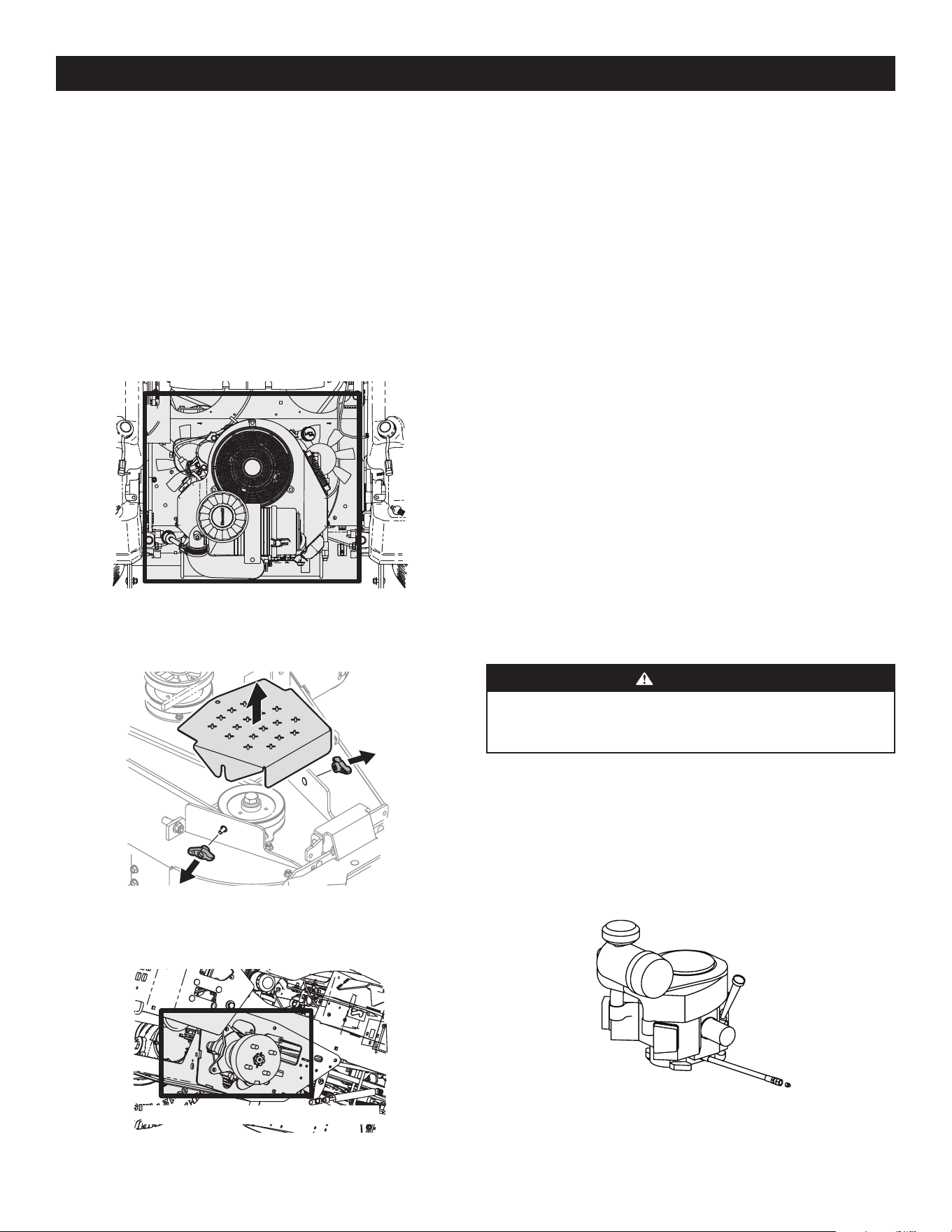
71
CUIDADO DEL PRODUCTO
Almacenamiento de la cortadora de césped
• Deje que la máquina se enfríe en un área abierta antes de almacenarla.
• No estacione la cortadora de césped cerca de cualquier material inflamable
(madera, ropa o productos químicos) o de llamas abiertas o cualquier otra
fuente de ignición (hornos, calentadores de agua u otros tipos de calefactores).
• Quite todos los materiales combustibles de la cortadora de césped antes de
guardarla. Vacíe las cajas de carga y los colectores o contenedores de césped.
• Si el tractor está equipado con una válvula de corte de combustible, interrumpa
siempre el flujo de combustible cuando almacene o transporte la cortadora
de césped.
• Verifique frecuentemente el sistema de combustible (circuitos, tanque, tapón
y accesorios) para ver si hay rajaduras o pérdidas. Repárelos y límpielos según
sea necesario.
Calibración
El sistema de Conducción Automática SurePath tendrá que ser calibrado en las
siguientes circunstancias:
• Cuando se realice un mantenimiento o reparación mayor en el frente.
• Cuando se reemplace el GPM o la columna de dirección completa.
Por favor, contáctese con un distribuidor de servicio autorizado para obtener más
información sobre la calibración del sistema.
MANTENIMIENTO
Motor
Consulte todas las instrucciones, especificaciones, procedimientos e intervalos de
mantenimiento del motor en el Manual del operador del motor.
CAMBIO DE ACEITE DEL MOTOR
ADVERTENCIA
Si el motor ha estado en funcionamiento recientemente, el motor, el silenciador
y las superficies metálicas circundantes estarán calientes y pueden causar
quemaduras en la piel. Tenga precaución para evitar quemaduras.
Mantenga el nivel de aceite como se indica en el Manual del operador del motor.
Tenga cuidado para que el aceite no toque las correas de transmisión.
Para realizar el cambio de aceite, proceda de la siguiente manera:
1. Haga funcionar el motor por un período corto para que el aceite del motor se
caliente. El aceite fluirá mejor y limpiará más impurezas. Tenga cuidado y evite
quemarse con el aceite caliente.
2. Ubique la manguera de drenaje de aceite del motor. Consulte la Figura 33.
Figura 33
3. Quite la manguera del clip que la sujeta al bastidor.
Una de las mejores maneras de mantener el funcionamiento eficiente de su cortadora
de césped y reducir el riesgo de incendio es eliminar regularmente la acumulación
de desechos de la cortadora de césped. Siga las recomendaciones a continuación y
contacte a su distribuidor autorizado si tiene alguna pregunta.
• Deje que la máquina se enfríe en un área abierta antes de limpiarla.
• No utilice agua en ninguna parte de la cortadora de césped, excepto en la
parte inferior de la plataforma de corte. Hacerlo puede dañar los cojinetes del
husillo de la cortadora de césped, el sistema eléctrico y el motor, lo que puede
provocar fallas prematuras. El uso de aire comprimido y/o de un soplador de
hojas mantendrá limpia la cortadora.
• Limpie alrededor del colector del escape, los fusibles, todo el cableado y mazos
de cables, tubo del silenciador, protector del silenciador, filtros de admisión del
motor y aletas de refrigeración, etc. Consulte la Figura 30.
Figura 30
• Limpie la parte superior de la plataforma de corte, debajo de las cubiertas de
husillos y del área de correas. Consulte la Figura 31.
Figura 31
• Limpie alrededor y cerca de la transmisión, eje y área de ventiladores. Consulte
la Figura 32.
No se muestra el volante para mayor claridad
Figura 32
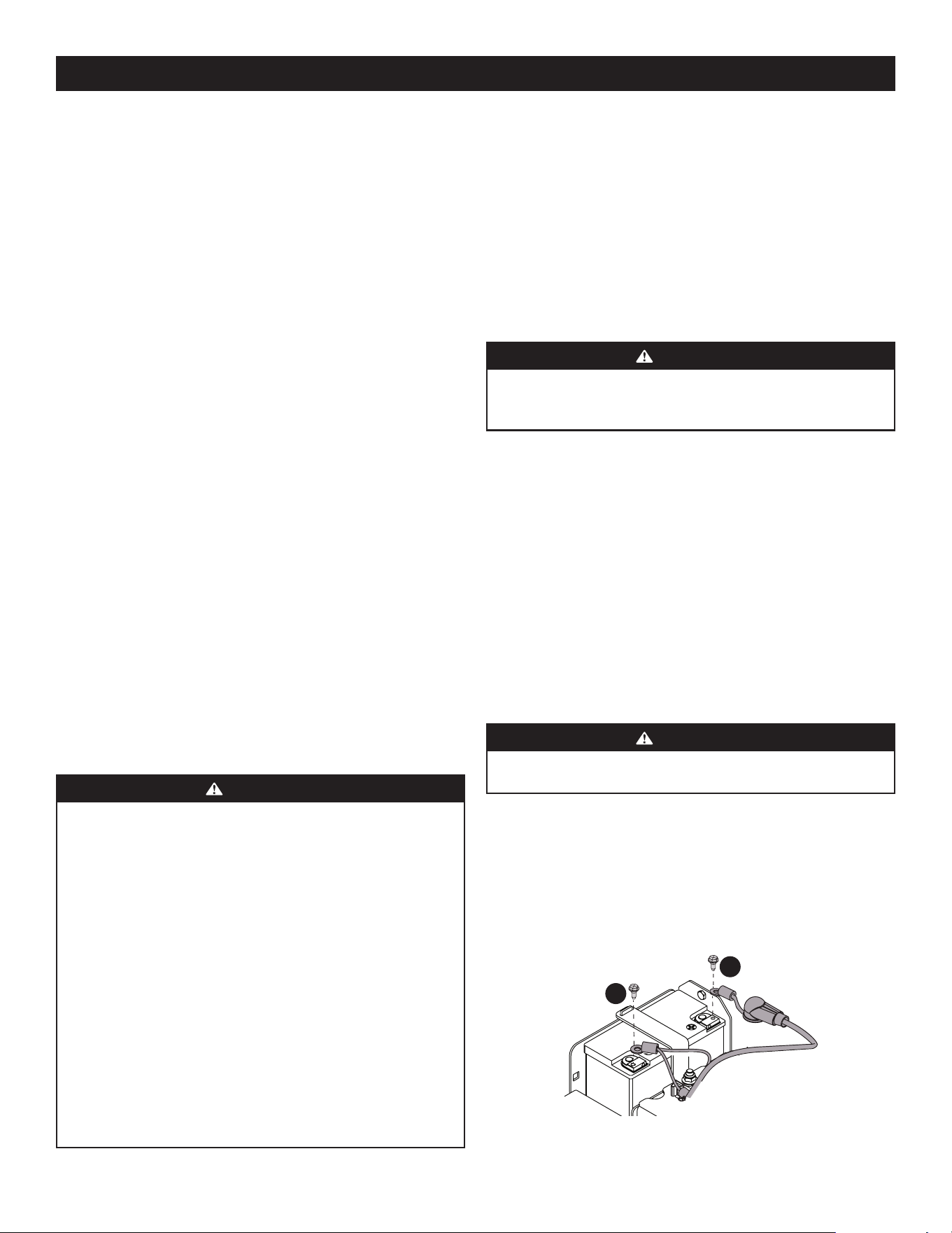
72
CUIDADO DEL PRODUCTO
4. Coloque el extremo libre de la manguera de drenaje de aceite en un depósito de
recolección de aceite adecuado que posea una capacidad de por lo menos 2.5
cuartos de galón (2.4 litros) para recoger el aceite usado.
NOTA: evite que ingrese aceite en el silenciador durante el drenaje.
5. Mientras sostiene el extremo libre de la manguera de drenaje de aceite sobre
el recipiente de recolección de aceite, desenrosque el tapón de la manguera
del extremo de la manguera. Consulte la Figura 33. Drene el aceite del motor
dentro del recipiente.
6. Quite el filtro de aceite para asegurarse de que se drene todo el aceite.
7. Una vez que haya drenado el aceite, limpie el aceite residual de la manguera de
drenaje de aceite. Enrosque el tapón de cabeza cuadrada dentro del accesorio
de la manguera de drenaje y apriete el tapón por completo.
8. Vuelva a colocar el filtro de aceite y cargue el motor con aceite nuevo según
las instrucciones del Manual del operador del motor. Consulte el Manual del
operador del motor para obtener información sobre el volumen y el peso del
aceite de motor.
9. Vuelva a colocar la manguera en el clip que la sujeta al bastidor.
Lubricación
Lubrique periódicamente todos los otros puntos de pivote con un aceite lubricante
de calidad.
Neumáticos
Controle la presión de aire de los neumáticos cada 50 horas de operación o una
vez por semana. Mantenga los neumáticos inflados a las presiones recomendadas.
El inflado inadecuado de un neumático reduce su vida útil y producirá un corte
irregular. Consulte los laterales de los neumáticos para averiguar las presiones de
inflado adecuadas. Respete las siguientes pautas:
• No infle los neumáticos por encima de la presión máxima que se muestra en el
lateral del neumático.
• No vuelva a inflar un neumático que se ha utilizado desinflado o desinflado en
extremo. Un gomero calificado debe inspeccionar y reparar el neumático.
Información sobre la Batería
ADVERTENCIA
En caso de que se produzca una salpicadura accidental de ácido en los ojos o la
piel, enjuague el área afectada inmediatamente con agua limpia fría. Consulte a
un médico inmediatamente.
Si el ácido salpica la ropa, en primer lugar dilúyalo con agua limpia, luego
neutralícelo con una solución de agua/amoníaco o bicarbonato/agua.
NUNCA conecte (o desconecte) las abrazaderas del cargador de la batería a la
batería si el cargador está encendido, ya que puede causar chispas.
Mantenga todas las fuentes de ignición (cigarrillos, cerillas, encendedores)
alejadas de la batería. El gas generado durante la carga puede ser combustible.
Como precaución adicional, cargue la batería únicamente en un área
bien ventilada.
Siempre proteja sus ojos y su piel y vestimenta cuando trabaje cerca de baterías.
Las baterías contienen ácido sulfúrico y pueden producir gases explosivos. Tenga
sumo cuidado cuando manipule baterías. Mantenga las baterías lejos del alcance
de los niños.
La batería puede generar riesgo de incendio o quemadura química si se la usa
incorrectamente. NO abra, desensamble, sobrecaliente o incinere la batería.
MANTENIMIENTO DE LA BATERÍA
• La batería se llena con ácido de batería y se sella en fábrica. Sin embargo, para
asegurar un ciclo de vida adecuado es necesario realizar cierto mantenimiento,
aún en las baterías ‘sin mantenimiento’.
• Rocíe los bornes y el cable expuesto con un sellador de bornes de batería, o
recubra los bornes con una capa delgada de grasa o vaselina para protegerlos
contra la corrosión.
• Siempre mantenga limpios y libres de corrosión los cables y los bornes de
la batería.
• Algunos modelos vienen equipados con una batería que contiene un electrolito
líquido. Manipule la batería con cuidado y evite inclinarla para evitar fugas.
ADVERTENCIA
Las baterías contienen ácido sulfúrico y pueden producir gases explosivos. Tenga
sumo cuidado cuando manipule baterías. Mantenga las baterías lejos del alcance
de los niños.
ALMACENAMIENTO DE LA BATERÍA
1. Cuando guarde la cortadora de césped durante períodos prolongados,
desconecte el cable negativo de la batería. No es necesario retirar la batería.
2. Todas las baterías se descargan durante el almacenamiento. Mantenga el
exterior de la batería limpio, especialmente la parte superior. Una batería sucia
se descarga con mayor rapidez.
3. La batería debe guardarse con carga completa. Una batería descargada
se puede congelar más pronto que una batería cargada. Una batería con
carga completa se guarda por más tiempo en temperaturas frías que en
temperaturas altas.
4. Vuelva a cargar la batería antes de volver a ponerla en servicio. Aun cuando la
cortadora de césped pueda arrancar, el sistema de carga del motor tal vez no
recargue totalmente la batería.
EXTRACCIÓN DE LA BATERÍA
ADVERTENCIA
Los contactos, bornes y accesorios de la batería contienen plomo y compuestos de
plomo. Lávese las manos después de estar en contacto con estos componentes.
1. Tire del asiento totalmente hacia adelante.
2. Retire el tornillo hexagonal que fija el conductor negativo negro (a) de la
batería al borne negativo de la batería (marcado ‘NEG’). Aleje el cable del
contacto negativo de la batería. Consulte la Figura 34.
3. Retire el tornillo hexagonal que fija el conductor positivo rojo (b) de la batería
al borne positivo de la batería (marcado POS). Aleje el cable del borne positivo
de la batería. Consulte la Figura 34.
a
b
Figura 34
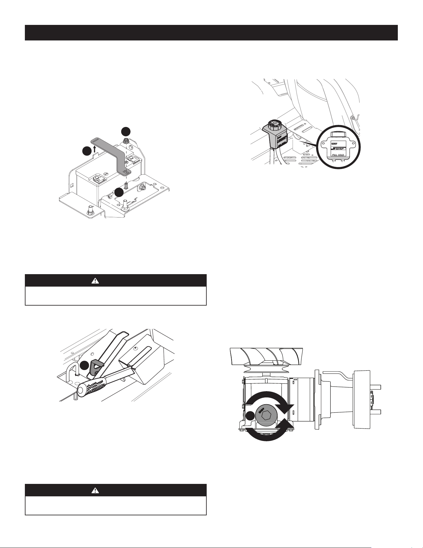
73
CUIDADO DEL PRODUCTO
4. Localice y sostenga el perno de carro (a) que está en el frente del soporte de la
batería (c) para evitar que se caiga. Consulte la Figura 35.
5. Retire la tuerca hexagonal (b) que fija el soporte de la batería (c) en su lugar.
Guarde el perno de carro y la tuerca de seguridad hexagonal para volver a
instalarlos más tarde. Consulte la Figura 35.
6. Levante el soporte de la batería (c) de la pestaña que está del lado izquierdo
de compartimiento de la batería y guárdelo para su posterior reinstalación.
Consulte la Figura 35.
a
b
c
Figura 35
Uso de las palancas de derivación de las transmisiones
Si por alguna razón la cortadora de césped no funciona o usted desea moverla, las
dos transmisiones hidrostáticas están equipadas con una varilla de derivación que
permite mover manualmente la cortadora a lo largo de distancias cortas.
ADVERTENCIA
No remolque la cortadora de césped, ni siquiera con la varilla de derivación
acoplada. Si lo hace, la transmisión sufrirá graves daños.
1. Active las válvulas de derivación de las transmisiones tirando de la palanca de
derivación (a) hacia arriba y luego a fondo hacia atrás. Consulte la Figura 36.
a
Figura 36
2. Para soltar la palanca de derivación (a), empuje la palanca hacia adelante.
Transmisión Hidrostática
La serie 900 viene equipada con dos bombas hidrostáticas/transejes integrados que
cuentan con un depósito de expansión del aceite de transmisión. En condiciones
operativas normales, no es necesario controlar el nivel de aceite del depósito de
expansión y no hace falta aceite adicional. Si controla el nivel de aceite de ese
depósito, proceda de la siguiente manera:
ADVERTENCIA
Controle el nivel de aceite ÚNICAMENTE antes de arrancar la cortadora de césped
cuando el aceite de transmisión está totalmente refrigerado.
1. Gire el asiento del operador hacia adelante y limpie el tapón del depósito y el
área que lo rodea para evitar que el aceite de transmisión se contamine con
residuos. Consulte la Figura 37.
Figura 37
2. Gire el tapón del depósito en sentido contrario al de las agujas del reloj para
retirarlo, luego controle el nivel de aceite del depósito. El aceite debe ser visible
en la base de la cubeta, pero el nivel del mismo NO debe estar por encima de la
línea de “LLENO FRÍO”. Consulte la Figura 37. NO LLENE EL DEPÓSITO.
3. Si fuese necesario agregar aceite debido a algún tipo de fuga, agregue
únicamente la cantidad suficiente de aceite para que el nivel llegue a la línea de
“LLENO FRÍO”. Vuelva a colocar el tapón y ajústelo por completo.
NOTA: antes del funcionamiento inicial de la cortadora de césped, el nivel de
aceite del depósito puede estar levemente por encima del máximo debido a
la presencia de aire en las líneas de aceite. El funcionamiento de la cortadora
de césped con el tiempo purgará el aire de las líneas y el nivel de aceite se
estabilizará en el máximo.
Para cambiar el aceite de la transmisión:
1. Extraiga el tapón del depósito de expansión de aceite de la transmisión.
2. Coloque un recipiente adecuado debajo del tapón de drenaje (a) que está
sobre la transmisión. Quite el tapón de drenaje (a) y deje drenar el aceite de la
transmisión. Consulte la Figura 38.
a
Figura 38
3. Con un par de alicates de punta de aguja o un imán, quite el filtro.
4. Vuelva a colocar el filtro y tapón de drenaje (torque de 115-135 pulg.-libras)
y llene el depósito de expansión lentamente hasta la línea de “LLENO FRÍO”.
Deje que el aceite de la transmisión circule por el sistema y recargue, si
fuese necesario.
5. Vuelva a colocar el tapón y ajústelo bien.
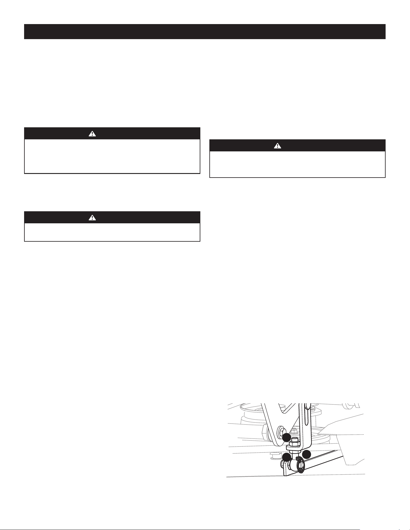
74
CUIDADO DEL PRODUCTO
Para sacar la cortadora del almacenamiento
1. Inspeccione el aceite del motor.
2. Cargue totalmente la batería e infle los neumáticos a la presión recomendada.
3. Llene el depósito de combustible con gasolina limpia y nueva.
4. Arranque el motor y déjelo andar en ralentí unos cuantos minutos para
asegurar que su funcionamiento sea adecuado.
5. Conduzca la cortadora de césped sin carga para estar seguro de que todos sus
sistemas funcionan correctamente.
AJUSTES
ADVERTENCIA
Apague el motor, retire la llave de encendido y coloque el freno de mano antes
de realizar ajustes. Proteja sus manos utilizando guantes reforzados cuando
manipule las cuchillas.
Nivelación de la Plataforma
NOTA: controle la presión de neumáticos de la cortadora de césped antes de realizar
cualquier nivelación de la plataforma. Consulte la sección Neumáticos para obtener
información sobre la presión de los neumáticos. Nivele siempre la plataforma de lado
a lado antes de alinearla de adelante hacia atrás.
NIVELACIÓN LADO A LADO
1. Estacione la cortadora sobre una superficie pavimentada plana, aplique el
freno de mano, apague el motor, retire la llave del interruptor de encendido
y desconecte los cables de bujías. Con el pedal de elevación de la plataforma,
coloque la plataforma de corte en la posición de 4” de altura de corte (esta
posición de 4” de altura de corte se recomienda para poder ver y obtener una
medición. Cualquier posición de altura de corte es aceptable en tanto pueda
obtenerse una medición correcta). Rote ambas cuchillas externas para que
queden perpendiculares a la cortadora de césped.
2. Mida la distancia desde la parte externa de la punta de la cuchilla izquierda
hasta el piso, y desde la parte externa de la punta de la cuchilla derecha hasta
el piso. Las dos mediciones obtenidas deben ser iguales. Si no lo son, continúe
con el siguiente paso.
3. Ajuste el perno de ojo (a) en la parte delantera izquierda de la plataforma para
que la altura desde la punta de la cuchilla externa derecha al piso coincida
con la de la punta de la cuchilla externa izquierda. Esto se hace aflojando las
contratuercas (b) en el perno de ojo (a) y apretando la contratuerca superior
(b) para elevar la plataforma y aflojando la contratuerca (b) para bajar la
plataforma. La altura de la punta de la cuchilla externa derecha se fija con el
perno de ojo derecho (a), por lo que debe ajustar la punta externa izquierda
para que coincidan. Consulte la Figura 39.
a
b
b
Figura 39
4. Cuando logre el ajuste correcto, vuelva a apretar las contratuercas (b).
Almacenamiento de la cortadora de césped
Si la cortadora de césped no a va a funcionar por un período prolongado (desde
treinta días hasta aproximadamente seis meses), se la debe preparar para el
almacenamiento. Guarde la cortadora de césped en un lugar seco y protegido. Si
guarda la cortadora afuera, cúbrala (incluidos los neumáticos) para protegerla contra
los fenómenos climáticos. Cada vez que se prepara la cortadora de césped para
dejarla fuera de uso se deben realizar los procedimientos descriptos más abajo.
1. Cambie el aceite y filtro de motor según las instrucciones suministradas en el
Manual del operador del motor que se incluye con este manual.
ADVERTENCIA
Nunca guarde la cortadora de césped con combustible en el depósito en un
lugar cerrado o con escasa ventilación, donde los gases del combustible pueden
llegar a una llama expuesta, una chispa o una luz piloto como la de un horno,
calentador de agua, secador de ropa, etc.
a. Para evitar que se formen depósitos de goma dentro del carburador
del motor y el motor sufra algún desperfecto, use un estabilizador de
combustible o vacíe por completo el sistema de combustible cuando
fuese a guardar la cortadora por un lapso de entre 30 y 90 días:
ADVERTENCIA
El combustible que queda en el depósito se deteriora y causa graves problemas
de arranque.
• Lea las instrucciones y recomendaciones del fabricante del producto.
• Agregue a la gasolina limpia y nueva la cantidad correcta de
estabilizador según la capacidad del sistema de combustible.
• Llene el depósito de combustible con combustible tratado y haga
funcionar el motor 2-3 minutos para estabilizar el combustible
dentro del carburador.
b. Vaciado del sistema de combustible para almacenamiento de más de
90 días:
• Antes de guardar la cortadora de césped, observe el consumo de
combustible a los efectos de hacerla funcionar hasta que el depósito
esté vacío.
• Haga funcionar el motor hasta que comience a detenerse. Use el
cebador para mantener el motor en funcionamiento hasta que se
haya agotado todo el combustible del carburador.
• Consulte el manual del operador del motor para drenar el
combustible del recipiente del carburador.
2. Limpie cuidadosamente el motor y toda la unidad.
3. Cargue totalmente la batería, luego desconecte el cable negativo de la batería
para evitar posibles descargas. Vuelva a cargar la batería periódicamente
durante el almacenamiento.
NOTA: retire la batería si ha estado expuesta a períodos prolongados de
temperaturas inferiores al congelamiento. Guarde en un lugar fresco y seco,
donde las temperaturas estén por encima del punto de congelamiento.
4. Lubrique todos los puntos de lubricación.
NOTA: no se recomienda el uso de una lavadora de presión ni de una manguera
de jardín para limpiar la cortadora de césped. Puede dañar los componentes
eléctricos, los husillos, las poleas, los rodamientos o el motor. El uso de agua
acortará la vida útil de la máquina y reducirá su capacidad de servicio.
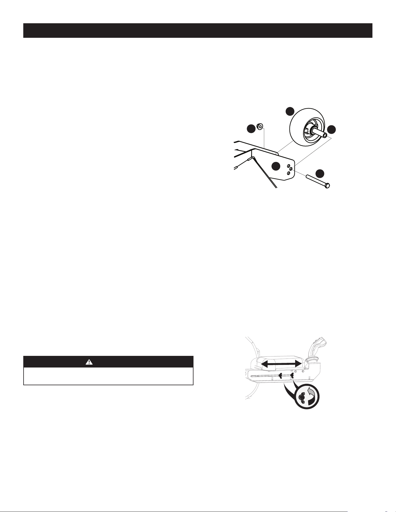
75
CUIDADO DEL PRODUCTO
1. Controle visualmente la distancia entre las ruedas calibradoras delanteras y el
suelo. Si las ruedas de calibración están cerca del suelo o lo tocan, es necesario
levantarlas. Si las ruedas de calibración se encuentran a más de 1/2 pulgada del
suelo, es necesario bajarlas.
2. Retire la tuerca de seguridad (a) que fija una de las ruedas de calibración
delanteras (b) a la plataforma. Retire la rueda de calibración (b), el tornillo
hexagonal (c) y el espaciador (d). Consulte la Figura 40.
a
b
c
d
e
Figura 40
NOTA: hay un par de ruedas de calibración delanteras en la punta de la
plataforma de 60”.
3. Inserte el tornillo hexagonal (c) en uno de los tres orificios de posicionamiento
del soporte (e) de la rueda de calibración delantera que le dará a la rueda de
calibración delantera (b), una separación de 1⁄4 a 1⁄2” del suelo.
4. Observe el orificio de posicionamiento de la rueda de calibración delantera (b)
que acaba de ajustar y ajuste la otra rueda de calibración delantera (b) en el
orificio de posicionamiento respectivo del otro soporte de rueda de calibración
delantera de la plataforma (e).
Ajuste del apoyabrazos del Panel de Control del Operador
Para ajustar el apoyabrazos derecho (lado del Panel de Control del Operador),
proceda de la siguiente manera:
1. Afloje las cuatro (4) tuercas de mariposa ubicadas debajo del apoyabrazos
derecho girando a mano en sentido contrario a las agujas del reloj. Consulte la
Figura 41.
Figura 41
2. Deslice la parte superior del apoyabrazos hacia adelante o atrás hasta que
quede en la posición preferida del operador.
3. Vuelva a ajustar a mano las cuatro tuercas de mariposa para fijar
el apoyabrazos.
NOTA: el cable que alimenta al Panel de Control del Operador corre a lo largo
de la parte de abajo del apoyabrazos derecho. No pellizque ni retuerza el cable
mientras ajusta el apoyabrazos.
NIVELACIÓN ADELANTE ATRÁS
1. Estacione la cortadora sobre una superficie pavimentada plana, aplique el
freno de mano, apague el motor, retire la llave del interruptor de encendido
y desconecte los cables de bujías. Con el pedal de elevación de la plataforma,
coloque la plataforma de corte en la posición de 4” de altura de corte (esta
posición de 4” de altura de corte se recomienda para poder ver y obtener una
medición. Cualquier posición de altura de corte es aceptable en tanto pueda
obtenerse una medición correcta). Rote ambas cuchillas externas para que
queden perpendiculares a la cortadora de césped.
2. Mida la altura que hay entre la cuchilla y el piso, en la punta de la cuchilla
derecha trasera. Aquí también asegúrese de medir la punta de la cuchilla en la
parte trasera de la cuchilla derecha cuando está alineada con la línea central de
la cortadora. La altura entre la cuchilla y el piso en la parte trasera de la punta
de la cuchilla debe ser de 1/8” a 1/4” superior a la de la punta delantera. Esto
se denomina inclinación de la cuchilla. La misma diferencia de altura se debe
aplicar a la cuchilla izquierda, medida adelante y atrás. La inclinación no debe
exceder de 1/16” si la altura de corte está por debajo de 1-1/2”.
3. Afloje las contratuercas (b) en la parte posterior izquierda y derecha de los
pernos de ojo (a). Consulte la Figura 39.
4. Comience en la parte posterior derecha para elevar la parte trasera de la
plataforma, ajuste la contratuerca superior (b) para elevar la plataforma o
afloje la contratuerca superior (b) para bajar la parte trasera de la plataforma.
Consulte la Figura 39.
5. Ajuste la contratuerca (b) en la parte trasera izquierda para eliminar la
“holgura” de la varilla roscada. Consulte la Figura 39.
6. Apriete ambas contratuercas inferiores (b) para asegurar el ajuste de la
plataforma. Consulte la Figura 39.
7. El ajuste final sería eliminar la “holgura” del varillaje trasero izquierdo si la
parte posterior de la plataforma se elevó ajustando las contratuercas (b) en el
perno de ojo (a). Afloje las contratuercas (b) y apriete la contratuerca superior
(b) para eliminar la “holgura”. Consulte la Figura 39.
8. En muchos casos será necesario ajustar la altura de la plataforma usando los
ajustes de ambos pernos de ojo (a) y el ajuste de inclinación para lograr las
alturas correctas entre cuchillas y piso. Si recuerda que el ajuste de la punta de
la cuchilla derecha delantera es fijo y usted nivela a esa altura, el ajuste de las
plataformas será más simple. Consulte la Figura 39 en la página 74.
Ajuste de las ruedas de calibración delanteras
ADVERTENCIA
Mantenga las manos y los pies alejados de la abertura de descarga de la
plataforma de corte.
Las ruedas calibradoras delanteras de la plataforma de la cortadora de césped
constituyen un mecanismo para el cuidado del césped y no se deben usar para
desplazarse sobre el piso. La posición de las ruedas de calibración delanteras de la
plataforma debe ser aproximadamente entre 1/4 y 1/2 pulgada por encima del nivel
del suelo cuando la plataforma se fija en el valor de altura deseado.
Usando la manija de elevación de la plataforma, fije la plataforma en el valor de
altura deseado, luego controle la distancia entre la rueda de calibración y el piso. Si es
necesario ajuste las ruedas de calibración delanteras de la siguiente forma:

76
CUIDADO DEL PRODUCTO
SERVICIO
Módulo de Posicionamiento Global (GPM)
No intente modificar ni reparar el GPM. Por favor, por cualquier problema que tenga
con el GPM consulte con un distribuidor de servicio autorizado.
Carga de la batería
Si la cortadora de césped ha estado guardada durante un tiempo, pruebe la batería y,
si es necesario, recárguela.
Una lectura de voltímetro o probador de carga de 12.4 voltios (CC) o menos en los
bornes de la batería indica que la batería debe cargarse.
• Debe utilizarse un cargador de batería AGM. La tasa recomendada de carga
es 1.1A/14.8V.
• Si su cargador de batería es automático, cargue la batería hasta que el cargador
indique que se ha completado la carga. Si el cargador no es automático, cargue
durante ocho (8) horas como mínimo.
Alternador auxiliar
Por favor, para reemplazar el alternador auxiliar, vea a un distribuidor de
servicio autorizado.
Arranque con puente
ADVERTENCIA
Si no se utiliza este procedimiento de arranque, podrían generarse chispas y
podría explotar el gas de la batería.
1. Conecte el extremo de un cable al borne positivo de la batería de la cortadora
de césped que no funciona; luego conecte el otro extremo de ese cable al borne
positivo de la batería de urgencia.
2. Conecte un extremo del otro cable al borne negativo de la batería de urgencia;
luego conecte el otro extremo de ese cable al marco de la cortadora de césped
que no funciona, a la mayor distancia posible de la batería.
3. Arranque la cortadora de césped que no funciona según las instrucciones de
arranque normales indicadas más arriba; luego desconecte los cables de puente
en orden exactamente inverso al de la conexión.
4. Haga controlar y reparar el sistema eléctrico de la cortadora de césped lo más
pronto que fuere posible, para eliminar la necesidad de usar cables de puente
para arrancarla.
Mantenimiento del sistema eléctrico
FUSIBLE
Los fusibles se encuentran levantando el asiento del operador. La mayoría de los
fusibles están en el módulo de distribución de energía (PDM) principal que se
encuentra a la derecha de la batería (consulte la Figura 42 para ver el diagrama de
fusibles y la Figura 43 para ver las asignaciones de los fusibles). Se trata de fusibles
automotores de enchufar estándar minitipo (ATM). Siempre reemplace con fusibles
de la misma capacidad. Dos fusibles adicionales, la Dirección Electrónica de Potencia
(EPS) y Alternador, están en portafusibles simples MAXI cerca del PDM principal.
Si se repite el problema de fusibles quemados, haga que un distribuidor de servicio
autorizado revise el sistema eléctrico de la cortadora de césped.
R4
R1 R2 R3 R4
F1
F2
F5
-10-
F4
-30-
B1
-15-
-25-
-10-
B1
F4 F1
F2F5
R1
R2 R3
R4
Figura 42
Referencia Valor Circuitos
F1: Fusible principal 25A Sistema de +12 V
F2: Luces 10A Sistema de luces (opcional)*
F4: Arranque 30A Solenoide de arranque
F5: GPM 10A GPM principal
EPS 60A Dirección Electrónica de Potencia
ALT 60A Alternador
*Se requiere sistema de +12 V para activar
Figura 43
Controles del funcionamiento del sistema de enclavamiento de
seguridad e interruptores
Los siguientes controles de funcionamiento deben realizarse a diario:
INTERRUPTOR DE LA PTO
1. Siéntese en el asiento del operador. Con los pedales de mando en la posición
neutral y el freno de mano aplicado, active el interruptor de la PTO tirando
hacia arriba de la perilla e intente arrancar el motor. El motor no debería
arrancar. Si lo hace, el interruptor de la PTO debe ser reemplazado. Consulte con
su distribuidor de servicio autorizado.
2. Si el motor no arranca, desconecte la PTO pulsando la perilla y arranque el
motor. Ahora conecte la PTO y las cuchillas deberían girar.
3. Si las cuchillas no giran, el interruptor de la PTO debe ser reemplazado, el
interruptor del asiento debe ser reemplazado o el embrague eléctrico de la PTO
debe ser reparado. Consulte con su distribuidor de servicio autorizado.
INTERRUPTOR DEL FRENO DE MANO
1. Siéntese en el asiento del operador. Con los pedales de mando en la posición
neutral y la PTO desactivada, suelte el freno de mano e intente arrancar el
motor. El motor no debería arrancar.
2. Si lo hace, el interruptor del freno de mano debe ser reposicionado o
reemplazado. Consulte con su distribuidor de servicio autorizado. Si el motor no
arranca, active el freno de mano y arranque el motor.
INTERRUPTOR DEL ASIENTO
1. Con los pedales de mando en la posición neutral, el freno de mano aplicado y la
PTO desactivada, arranque el motor. Ahora suelte el freno de mano y levántese
del asiento. Libere el asiento del operador y el motor debería detenerse. Si el
motor no se detiene, se debe reemplazar el interruptor del asiento. Consulte
con su distribuidor de servicio autorizado.
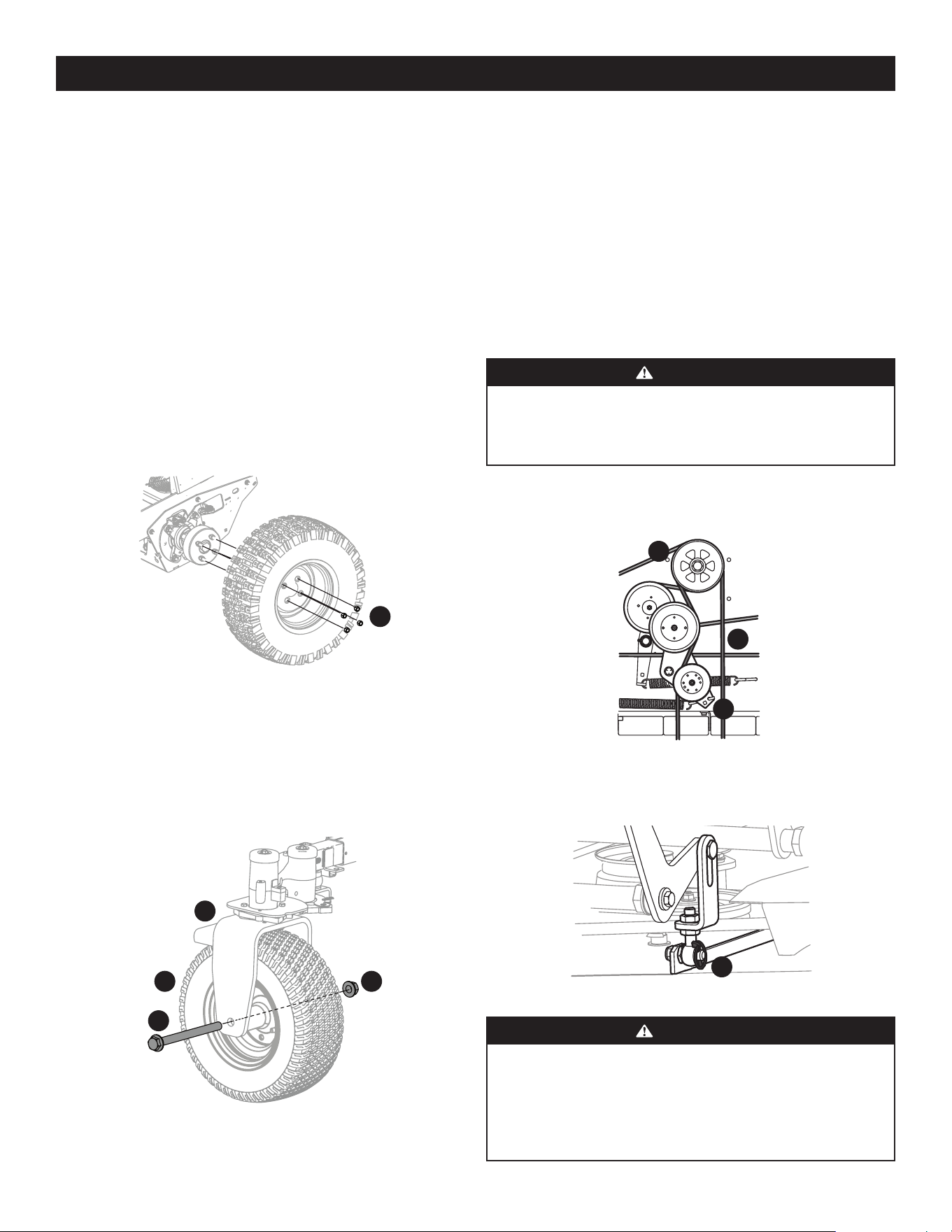
77
CUIDADO DEL PRODUCTO
2. Con las palancas de mando en la posición neutral, el freno de mano aplicado
y la PTO desactivada, siéntese en el asiento del operador y arranque el motor.
Conecte la PTO y las cuchillas deberían comenzar a girar. Levántese levemente
del asiento del operador y las cuchillas deberían detenerse. Si las cuchillas
no se detienen al desmontar el asiento del operador, se debe reemplazar el
interruptor del asiento. Consulte con su distribuidor de servicio autorizado.
EMBRAGUE ELÉCTRICO DE LA PTO
1. Este embrague se acciona cuando el motor está funcionando, el operador
está en el asiento del operador y la PTO está accionada. Normalmente, este
embrague eléctrico es un dispositivo libre de problemas. Si ocurre un problema
y las cuchillas no giran, revise primero el fusible de 25 A; luego, inspeccione el
mazo de cables y las conexiones con el interruptor del asiento, el interruptor de
la PTO y el embrague eléctrico de la cuchilla. Luego, revise el interruptor de la
PTO y el embrague eléctrico de la cuchilla. Si el embrague de la PTO todavía no
funciona correctamente, consulte con un distribuidor de servicio autorizado.
Extracción/Reemplazo de los neumáticos traseros
1. Quite las cuatro tuercas de las ruedas (a) para retirar el neumático. Consulte la
Figura 44.
a
Figura 44
2. Vuelva a instalar los neumáticos usando las cuatro tuercas de las ruedas.
Consulte la Figura 44. Ajuste las tuercas de las ruedas (a) con un par de 65 –
70 pies-libras.
Extracción/Reemplazo de los neumáticos delanteros
1. Quite el tornillo hexagonal (a) y la tuerca de seguridad bridada (b) que fija la
rueda delantera (c) al conjunto de caballete (d). Consulte la Figura 45.
a
bc
d
Figura 45
2. Para volver a instalar o reemplazar el neumático delantero, invierta el Paso
1. Ajuste los elementos de ferretería con una presión de 75-90 pies-libras.
Consulte la Figura 45.
Sensor de velocidad (neumáticos traseros)
Por favor, vea a un distribuidor de servicio autorizado para reemplazar o ajustar el
sensor de velocidad.
Retiro de la plataforma
Retire la plataforma de la cortadora de césped de la siguiente forma:
1. Baje la plataforma al suelo. Capte la elevación de la plataforma colocando el
pasador de horquilla detrás de la posición más baja.
2. Enganche el freno de mano. Retire la llave de encendido y el tapón de las bujías.
ADVERTENCIA
El silenciador y cualquier pieza cercana en la parte trasera de la cortadora podrían
estar sumamente calientes y causar quemaduras graves. Tenga mucho cuidado
cuando se encuentre cerca del silenciador. Deje que el silenciador se enfríe
totalmente antes de retirar la correa de la polea de la toma de fuerza (PTO).
3. Con una llave de 1/2” en el soporte de polea loca (a), gire la llave hacia la
derecha de la cortadora y deslice la correa de la PTO (b) para sacarla de la polea
de la PTO (c). Consulte la Figura 46.
c
a
b
Figura 46
4. Extraiga los cuatro pasadores Lynch (a) que aseguran la plataforma al conjunto
de elevación. Consulte la Figura 47.
a
Figura 47
ADVERTENCIA
El resorte está bajo tensión debido al peso de la plataforma. Al retirar los brazos
de elevación de la plataforma la tensión de los resortes pasará de la plataforma
al pedal de elevación de plataforma. La omisión de capturar el pedal de elevación
de la plataforma colocando el pasador de horquilla detrás de la posición más baja
mientras quita el varillaje de elevación de la plataforma hará que se retraiga y
podría causar lesiones personales.
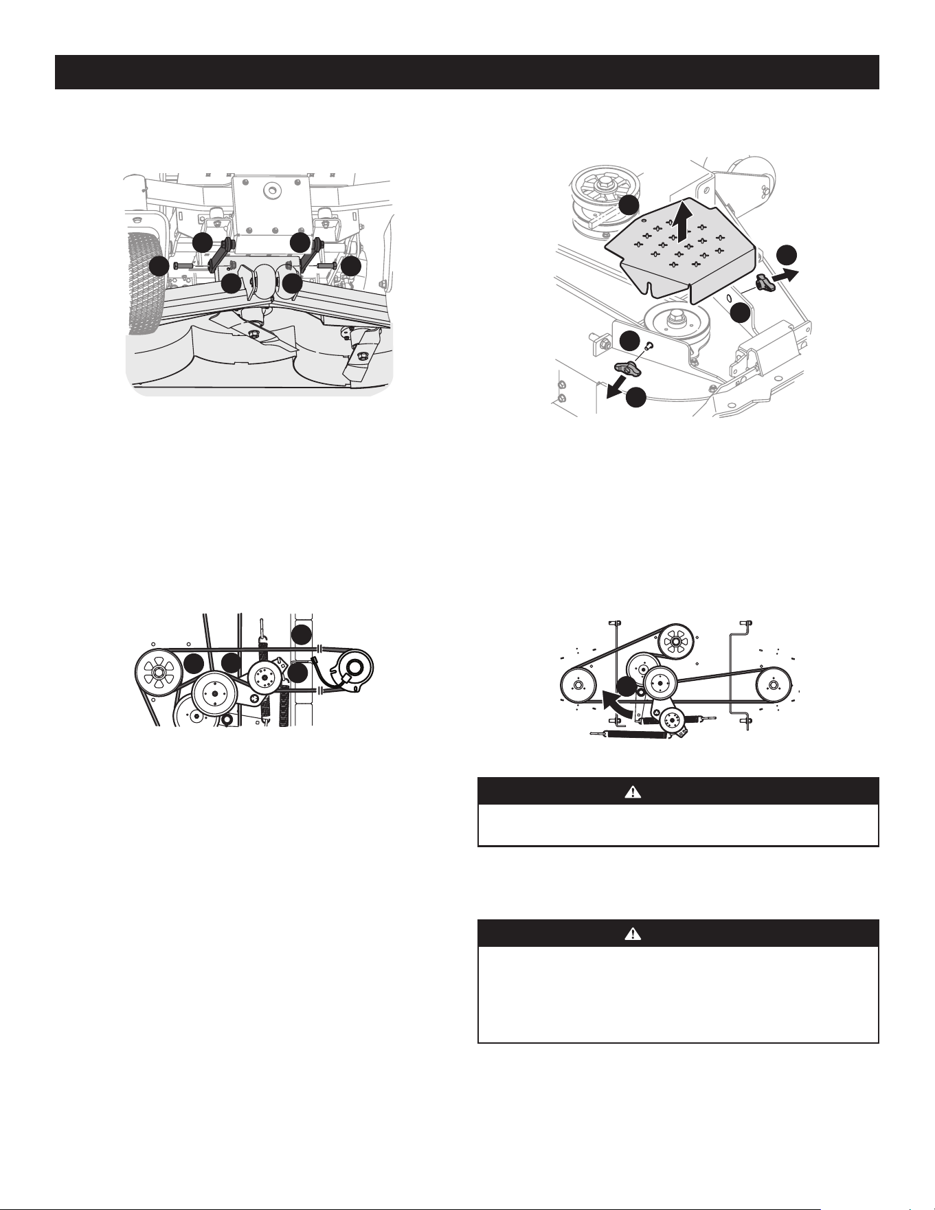
78
CUIDADO DEL PRODUCTO
5. Extraiga los tornillos hexagonales (a) y las tuercas de seguridad bridadas (b)
que sujetan las varillas de control frontal de la plataforma (c) a la plataforma.
Consulte la Figura 48.
a a
b b
c c
Figura 48
6. Gire las ruedas delanteras como si fuera a realizar un giro de pivote.
7. Desplace la plataforma hacia el lado derecho de la cortadora de césped
y extráigala.
8. Para instalar realice el procedimiento en sentido inverso.
Cambio de la correa de la PTO
1. Extraiga la correa de la PTO (a) de la cubierta siguiendo las instrucciones que
figuran en la sección Retiro de la plataforma y luego quítela de alrededor del
embrague de la PTO. Consulte la Figura 49.
b
a
c
d
Figura 49
2. Coloque la correa de la PTO (a) como se muestra en Figura 49.
3. Después de pasar la correa alrededor de la polea de la PTO (b), use una llave
de 1/2” (2 mm) en el soporte de la polea loca (c) y gire hacia la derecha de
la cortadora para terminar de pasar la correa alrededor de la polea loca (d).
Consulte la Figura 49.
4. Vuelva a instalar la plataforma invirtiendo los pasos anteriores.
Cambio de la correa de plataforma
1. Coloque el freno de mano. Retire la llave de encendido y los dos tapones de
las bujías.
2. Quite la correa de la PTO (consulte Retiro de la plataforma).
3. Para quitar las cubiertas de la correa (a), quite las perillas de mariposa (b) de los
tornillos de carro (c) que las aseguran a la plataforma. Consulte la Figura 50.
a
b
b
c
c
Figura 50
4. La tuerca de apriete rápido debería sostener el tornillo de carro (c) y el perno
de lengüeta en su lugar; de lo contrario, vuelva a instalar como se muestra en
la Figura 50.
5. Con una llave de 1/2” inserte el extremo en el orificio cuadrado de 1/2” en el
montaje de polea loca de la plataforma (a) y rote el montaje de polea loca de
la plataforma (a) hacia la derecha. Consulte la Figura 51. Mientras sostiene el
montaje de polea loca (a) de la plataforma, afloje la correa de la plataforma de
la polea y deslice la correa lejos de la polea.
a
Figura 51
ADVERTENCIA
Evite las lesiones por compresión. Al extraer la correa, no coloque nunca los dedos
en el resorte intermedio o entre la correa y una polea.
6. Coloque la correa nueva como se muestra en la Figura 51. Luego vuelva a
instalar la plataforma y la correa de la PTO.
Reemplazo de la correa de transmisión
ADVERTENCIA
Antes de realizar cualquier tarea de mantenimiento, desconecte la PTO, accione
la palanca del freno de mano, gire la llave de encendido a la posición “OFF”
(apagado) y retire la llave del interruptor. El silenciador y el motor se recalientan
y pueden producir quemaduras. Deje que la máquina se enfríe por lo menos 5
minutos antes de realizarle un servicio.
1. Quite la correa de la PTO solamente del embrague; para liberar tensión sobre la
correa de la PTO, consulte Retiro de la plataforma.
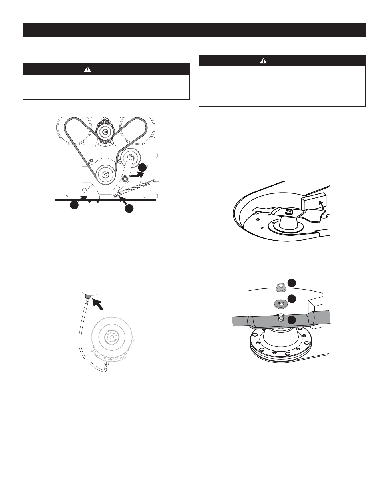
79
CUIDADO DEL PRODUCTO
Cambio de las cuchillas
ADVERTENCIA
Antes de realizar cualquier tarea de mantenimiento, desconecte la PTO, accione
la palanca del freno de mano, gire la llave de encendido a la posición “OFF”
(apagado) y retire la llave del interruptor. Proteja sus manos utilizando guantes
reforzados cuando manipule las cuchillas. Cuando realice el mantenimiento de la
plataforma de corte, tenga cuidado para no cortarse con las cuchillas filosas.
1. Extraiga la plataforma como se indica en la sección Retiro de la plataforma.
2. Para tener un acceso más fácil, invierta la plataforma, luego suba el frente de la
plataforma aproximadamente un pie y bloquéela en esa posición.
Para sacar la cuchilla:
1. Asegure que la cuchilla no gire en sentido contrario a las agujas del reloj
durante el servicio colocando un bloque de madera entre la cuchilla y la carcasa
de la plataforma, consulte la Figura 54, o envuelva un extremo de la cuchilla
con un trapo y sosténgala firmemente.
Figura 54
2. Quite la tuerca de seguridad bridada (a) y la arandela plana (b) del eje del
husillo y extraiga la cuchilla (c). Consulte la Figura 55.
a
b
c
Figura 55
Para volver a colocar la cuchilla:
1. Coloque la cuchilla sobre el eje del husillo. Asegúrese de instalar la cuchilla
con el lado marcado “Bottom” (inferior), “Grass Side” (lado inferior) o con un
número de pieza estampado orientado hacia el piso cuando la plataforma se
vuelva a instalar en la cortadora y en la posición de funcionamiento.
2. Libere tensión de la polea loca quitando el resorte del brazo de la polea loca.
Consulte la Figura 52.
ADVERTENCIA
El resorte está bajo tensión debido al peso de la plataforma. Tenga cuidado
al extraerlo pues podría causar lesiones personales. Use guantes y anteojos
de seguridad.
a
b
c
Las transmisiones hidrostáticas no se
muestran para mayor claridad
Vista desde
debajo de
la cortadora
mirando
hacia arriba
Figura 52
3. Gire el brazo de la polea loca para sacarlo del paso de la correa de la PTO.
Consulte (b) en la Figura 52.
4. Quite el soporte anti-rotación del bastidor aflojando las dos tuercas que lo fijan
a la plataforma. Consulte (c) en la Figura 52.
5. Desenchufe el conector eléctrico de la carcasa del embrague. Deje a un
costado estos elementos para la instalación posterior, como se indica en estas
instrucciones. Consulte la Figura 53.
Figura 53
6. Retire la correa de transmisión existente.
7. Pase la correa nueva alrededor del embrague y de la polea loca del motor como
se muestra en la Figura 52.
8. Vuelva a instalar el conector eléctrico, el soporte anti-rotación, el brazo de la
polea loca y la correa de la PTO invirtiendo los pasos 1-5.
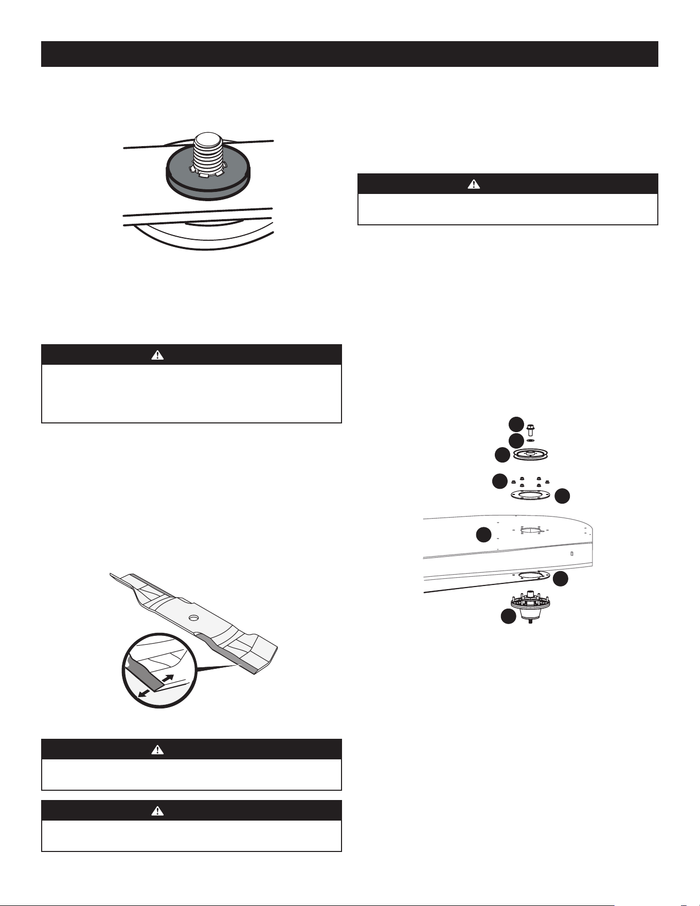
80
CUIDADO DEL PRODUCTO
2. Con cuidado coloque la arandela plana en el eje del husillo. Asegúrese de que
las ranuras en la base de las roscas del eje de husillo se alinean con las ranuras
de la arandela. Consulte la Figura 56.
Figura 56
3. Fije la cuchilla para que no gire hacia la derecha al volver a instalar la tuerca de
seguridad bridada (la dirección opuesta a la extracción de la cuchilla).
4. Instale la tuerca de seguridad bridada en el eje del husillo sobre la cuchilla y la
arandela plana. Ajuste hasta 100-130 pies-libras (136-176 N-m).
ADVERTENCIA
Nunca corte el césped con las cuchillas desafiladas. Si las cuchillas están dobladas
es necesario cambiarlas. Las cuchillas de corte son filosas y pueden causar
lesiones graves. Para evitar lesiones, envuelva la superficie de corte de la cuchilla
con un paño o use guantes gruesos.
Afilado de las cuchillas
1. Coloque el freno de mano.
2. Limpie cualquier desecho que quede en las cuchillas. Mantenga siempre las
cuchillas afiladas y sin acumulación de desechos.
3. Para afilar las cuchillas de corte de forma adecuada, extraiga cantidades iguales
de metal de ambos extremos de las cuchillas a lo largo de los bordes cortantes,
de forma paralela al borde de caída, a un ángulo de 25° a 30°. Afile siempre
cada borde de las cuchillas de corte de forma pareja para mantener un centrado
adecuado entre las mismas. Consulte la Figura 57.
Figura 57
ADVERTENCIA
Si una cuchilla está doblada o de otro modo dañada, reemplace la cuchilla por
una nueva. Use solamente cuchillas originales.
ADVERTENCIA
Una cuchilla mal centrada causará exceso de vibración, puede dañar la máquina
y/o causar lesiones personales.
4. Pruebe el centrado de la cuchilla usando un compensador de cuchillas. Afile el
metal del lado pesado hasta que quede bien centrada.
NOTA: cuando reemplace la cuchilla, asegúrese de instalarla con el lado
marcado “Bottom” (inferior) o “Grass Side” (lado de corte) (o con un número de
pieza estampado) orientado hacia el piso cuando la cortadora de césped está
en posición de funcionamiento.
ADVERTENCIA
Utilice una llave de torsión para ajustar la tuerca de brida hexagonal del husillo
de la cuchilla entre 100 pies-libras y 130 pies-libras.
Cambio del conjunto del husillo
1. Extraiga la plataforma como se indica en la sección Retiro de la plataforma.
2. Levante la parte delantera de la plataforma de corte aproximadamente un pie y
trábela en esa posición.
3. Extraiga la cubierta de la plataforma.
4. Retire las correas de transmisión. Consulte Reemplazo de la correa
de transmisión.
5. Saque la cuchilla. Consulte Cambio de las cuchillas.
6. Extraiga el tornillo de seguridad hexagonal (a) y las arandelas planas (b) que
aseguran las poleas del husillo de la derecha e izquierda (c) al conjunto del
husillo (d). Consulte la Figura 58.
b
a
c
f
e
h
g
d
Figura 58
7. Extraiga las seis (6) tuercas de seguridad bridadas (e) que aseguran los
conjuntos de husillo del lado derecho e izquierdo (d) y las placas de soporte (f) a
la carcasa de la plataforma (g). Consulte la Figura 58.
NOTA: no es necesario quitar la placa de soporte de la plataforma (h) a menos
que se estén reemplazando los tres husillos. Consulte la Figura 58.
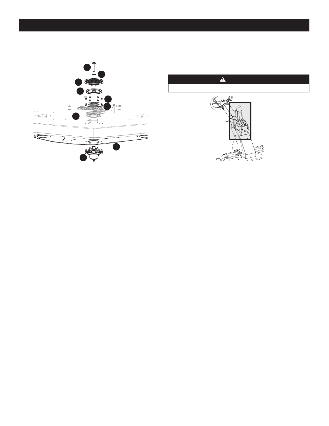
81
CUIDADO DEL PRODUCTO
Mantenimiento
• Nunca lave el GPM. Si fuese necesario, limpie el GPM solamente con una toalla
limpia de microfibra. Nunca cubra la antena del GPM. Si cubre la antena del
GPM, incluso con ciertos tipos de adhesivos, se inhibirá la señal del GPS lo cual
desactivará la función autónoma. Consulte Figura 60.
ADVERTENCIA
No bloquee el GPM.
Figura 60
• Se pueden acumular residuos en cualquier parte de la cortadora de césped,
especialmente en superficies horizontales. Puede ser necesario realizar
una limpieza adicional cuando corte césped en condiciones secas o cuando
haga abono.
• Las fugas y los derrames de combustible o de aceite y la lubricación excesiva
también pueden convertirse en lugares de acumulación de residuos. La
reparación de las fugas y la limpieza inmediata de los derrames de aceite o de
combustible pueden ayudar a reducir los riesgos de incendio.
• Además de limpiar la cortadora de césped antes de utilizarla y antes de
guardarla, no intente cortar césped demasiado crecido (de 25 cm [10 in] o más
de altura), seco (como un pastizal) ni pilas de hojas secas. El césped o las hojas
secas pueden entrar en contacto con el escape del motor y/o acumularse en la
plataforma de corte presentando un potencial peligro de incendio.
Módulo de Posicionamiento Global (GPM)
No intente modificar ni reparar el GPM. Por favor, por cualquier problema que tenga
con el GPM consulte con un distribuidor de servicio autorizado.
8. Extraiga el tornillo de seguridad hexagonal (a) y la arandela plana (b) que
aseguran la polea de transmisión (c) y la polea del husillo central (d) al conjunto
del husillo (e). Consulte la Figura 59.
a
b
c
d
f
h
e
i
g
Figura 59
9. Extraiga las seis (6) tuercas de seguridad bridadas (f) que aseguran la polea
del husillo central (d), el conjunto del husillo (e) y las placas de soporte (g) a la
carcasa de la plataforma (h). Consulte la Figura 59.
NOTA: no es necesario quitar la placa de soporte (i) de la plataforma a menos
que se estén reemplazando los tres husillos. Consulte la Figura 59.
10. Para instalar el conjunto del husillo realice el proceso en orden inverso. Cuando
instale el nuevo conjunto del husillo, asegúrese de instalar los elementos de
ferretería exactamente como se muestra en la Figura 58. Ajuste los tornillos de
seguridad hexagonales a 250 pies-libras y las tuercas de seguridad bridadas a
21-32 pies-libras.
Cambio de la Correa de Transmisión
Para cambiar la correa de transmisión de la cortadora, se deben retirar varios
componentes y se requieren herramientas especiales. Solicite a un distribuidor de
servicio autorizado que realice el reemplazo de la correa de transmisión.
Arrastre de la cortadora de césped
El desplazamiento lento es el movimiento leve de la cortadora hacia adelante o hacia
atrás cuando el acelerador está activado y los pedales de control de la velocidad están
en posición neutra. Si la cortadora de césped se desplaza lentamente, consulte a su
distribuidor de servicio autorizado.
SISTEMA DE CONDUCCIÓN AUTOMÁTICA SUREPATH
NOTA: la funcionalidad del sistema de Conducción Automática SurePath requiere
conectividad con software y servicios. El precio del producto incluye el primer año
de su suscripción. Todos los años subsiguientes tendrán que renovarse al costo
actual de la suscripción. Para más detalles, y para comprar una suscripción, por favor
visite cubcadet.com/surepath.

82
CUIDADO DEL PRODUCTO
SOLUCIÓN DE PROBLEMAS
ADVERTENCIA
Antes de realizar cualquier tipo de mantenimiento o servicio, desactive todos los controles y detenga el motor. Espere a que se detengan completamente todas las piezas
móviles. Desconecte los cables de las bujías y el cable negativo de la batería para evitar un arranque involuntario. Utilice siempre anteojos de seguridad durante el
funcionamiento o mientras ajusta o repara este equipo.
En esta sección se analizan problemas menores de servicio.
Problema Causa Solución
Excesiva vibración 1. Cuchilla de corte floja o descentrada.
2. Cuchilla de corte dañada o doblada.
1. Apriete la cuchilla y el husillo.
2. Reemplace la cuchilla.
Corte irregular 1. Plataforma nivelada incorrectamente.
2. Cuchilla de corte floja o descentrada.
3. Presión de neumáticos desigual.
1. Haga un ajuste de la plataforma de lado a lado.
2. Afile o cambie la cuchilla de corte.
3. Verifique y corrija la presión de los cuatro neumáticos.
La cortadora de césped no procesa
los recortes como abono
1. La velocidad del motor es demasiado lenta.
2. Pasto mojado.
3. Pasto demasiado alto.
4. Cuchilla desafilada.
1. Coloque el control del acelerador en la posición FAST
(velocidad rápida) (representada con una liebre).
2. No procese abono cuando el pasto está mojado.
3. Corte una vez a una altura de corte elevada y luego
vuelva a realizar el corte a la altura deseada, o siga una
ruta de corte más estrecha.
4. Afile o cambie la cuchilla.
El motor no arranca 1. Toma de fuerza (PTO)/cuchillas activadas.
2. Fusible quemado.
3. No está puesto el freno de mano.
1. Coloque la palanca de activación de las cuchillas en la
posición de desactivación (OFF).
2. Reemplace los fusibles. Reemplace con un fusible de igual
capacidad, si fuese necesario.
3. Coloque el freno de mano.
Consulte el Manual del Operador del Motor.

83
CUIDADO DEL PRODUCTO
Problema Causa Solución
Sistema de Conducción
Automática SurePath
NOTA: los problemas en el sistema de
Conducción Automática SurePath se
pueden resolver apagando la cortadora,
esperando 10 segundos y volviendo a
encender la cortadora de césped.
1. Las luces indicadoras/de advertencia no parpadean en
azul después de girar la llave.
1. Revise los fusibles. Reemplace con un fusible de igual
capacidad, si fuese necesario.
2. Las luces indicadoras/de advertencia no se ponen fijas en
luz verde.
2. Aléjese de árboles y edificios. Corrobore que nada esté
bloqueando el GPM.
3. El cortacésped está en un área abierta, pero las luces
indicadoras/de advertencia permanecen parpadeando en
verde con rojo periódico.
3. Revise la potencia de la señal del celular.
4. La cortadora está en un área abierta pero las luces
indicadoras/de advertencia siguen parpadeando en verde
(sin rojo periódico).
4. Verifique la suscripción a SurePath Auto Steer de la
siguiente manera:
• Asegúrese de que la suscripción anual no haya expirado.
• Revise si la cortadora se ha movido del estado en el
cual se activó la suscripción del sistema de Conducción
Automática SurePath.
• Comuníquese con un distribuidor de servicio autorizado si
los elementos anteriores no se resuelven.
5. Las luces indicadoras/de advertencia parpadean en
amarillo cuando presiona un botón.
5. Revise lo siguiente:
• El sistema de Conducción Automática SurePath no está listo.
Espere a que el indicador del GPS se ponga fijo en verde.
• El cortadora de césped no ha recorrido la distancia mínima
recomendada para permitir el ajuste de la línea de corte.
Consulte Establecimiento de la línea de corte (modo de
Conducción Automática SurePath).
• Restablecimiento inválido de la línea de corte. Consulte
Borrado de la línea de corte (modo de Conducción
Automática SurePath).
6. Las luces indicadoras/de advertencia parpadean en
amarillo mientras está en el modo de Conducción
Automática SurePath.
6. Velocidad demasiado rápida del la cortadora. Reducir
la velocidad.
7. El indicador del GPS está encendido pero el modo de
Conducción Automática SurePath no se conecta.
7. Reanude el uso en modo manual y contáctese con un
distribuidor de servicio autorizado para revisar los
fallos activos.
8. Las luces indicadoras/de advertencia parpadean en
rojo mientras el sistema se está usando en modo de
Conducción Automática SurePath.
8. Verifique lo siguiente:
• Si el cortacésped está debajo de un árbol o cerca de una
estructura, muévase a un área abierta y verifique que
nada esté bloqueando el GPM.
• Revise la potencia de la señal del celular.
• Reanude el uso en modo manual y contáctese con
un distribuidor de servicio autorizado para revisar los
fallos activos.
9. Las luces indicadoras/de advertencia parpadean en rojo. 9. Reanude el uso en modo manual y contáctese con un
distribuidor de servicio autorizado para revisar los
fallos activos.
10. El modo de Conducción Automática SurePath deja áreas
sin cortar entre pasadas de corte.
10. Gire la perilla de Ancho de Corte en sentido contrario a las
agujas del reloj para aumentar el traslape de corte.
11. El modo de Conducción Automática SurePath está
traslapando demasiado entre pasadas de corte.
11. Gire la perilla de Ancho de Corte en sentido de las agujas
del reloj para reducir el traslape de corte.
12. Es necesario desactivar el modo de Conducción
Automática SurePath.
12. Para desactivar el modo de dirección automática
de SurePath:
• Quite el fusible del GPM (etiquetado como F5:GPM que
se encuentra en la caja de fusibles debajo del asiento
del operador) para desactivar el sistema de Conducción
Automática SurePath.
• Comuníquese con un distribuidor de servicio autorizado.

84
PIEZAS DE REPUESTO Y ACCESORIOSPIEZAS DE REPUESTO Y ACCESORIOS
Piezas de repuesto
Número
de pieza
Descripción
954-04319 Correa de la plataforma
954-05128
954-05129
Correa de PTO (plataforma de 60”)
Correa de PTO (plataforma de 72”)
754P07134 Correa de transmisión
942-04415
742-04415-ES
942-05179
Cuchilla de elevación alta, 21.0 (plataforma de 60”)
Cuchilla de elevación alta Eversharp™, 21.0 (plataforma de 60”)
Cuchilla de elevación alta, 25.0 (plataforma de 72”)
918-08473 Husillo de plataforma
634-05451 Rueda de plataforma
731-11926 Protector antideslizante de la plataforma
951-15243 Tapón de combustible
946-05260 Cable de control del acelerador
946-05341B Control del cebador
925-06908 Llave de encendido
946-05103A Cable del freno de mano
931-05396C
931-05419
Conjunto de canal (plataformas de 60”)
Conjunto de canal (plataformas de 72”)
634-05192
634-05428B
Conjunto de ruedas traseras, 26 x 12-12
Conjunto de ruedas delanteras, 16 x 6.5-8
02003749 Placas de fricción de eje delantero, 1.125 x 5.0
741-0941A Cojinetes de bolsa de eje delantero, 1.0 x 52 x 15
Complementos y accesorios
Número de pieza Descripción
59A30060150 Embolsadora triple
59A30062150 Kit de soplador 60”
59A30063150 Ventilador de embolsadora 60”
19B70039100 Kit de abono de 60”
59A30053150 Kit de abono de 72”
490-241-0036 Kit de cadena de neumáticos traseros
59B30021150 Tomacorriente de 12 V
59B30011150 Kit de luz de trabajo
59A30018150 Kit de rueditas
59A30057150 Neumático de ultra-tracción, 26 x 12-12
59A30058150 Neumático de ultra-tracción, 24 x 12-12
490-850-0008 Sifón de aceite
490-850-0005 Herramienta de extracción de cuchillas
490-325-0020 Sellador para neumáticos
490-900-0045 Llave del filtro de aceite
490-900-0062 Pulverizador antiadherente Armortek
490-000-0028 Producto de limpieza para carburador y cebador

85
NOTES/NOTAS

CUB CADET LLC: GARANTÍA LIMITADA
100016 Rev J (13 octubre de 2021)
La garantía limitada que se extiende en el presente documento es otorgada por Cub Cadet LLC en relación a un nuevo producto Cub Cadet® LLC (en adelante,
“Producto”) adquirido y utilizado en los Estados Unidos y/o Canadá al Comprador Inicial (como se define en este documento). La presente garantía limitada
no cubre los Sistemas de control de emisiones y no constituye una Declaración de garantía del control de las emisiones federal, según lo definido por las leyes
federales de los Estados Unidos. Consulte la Declaración de garantía de control de emisiones federal que se incluye en el manual del operador para conocer las
garantías que cubren los Sistemas de control de emisiones.
Alcance de la Garantía Limitada
Cub Cadet LLC garantiza que el Producto (excepto en lo que respecta a los componentes y circunstancias definidos a continuación como “Exclusiones”) estará libre
de defectos en los materiales y la mano de obra durante el Período de Garantía, como se define a continuación. Para los propósitos de esta garantía limitada, el
“Comprador Inicial” es la primera persona en adquirir este Producto nuevo de un representante, distribuidor y/o minorista Cub Cadet autorizado de estos productos,
incluido un tercero para quien el mencionado haya sido comprado como regalo. Esta garantía limitada no es transferible. Durante el Período de Garantía, Cub Cadet
LLC reparará o reemplazará, a su juicio, cualquier pieza original cubierta por la presente garantía limitada y que se determine que presenta algún defecto en la
mano de obra o los materiales. “Uso comercial” se definirá como cualquier uso comercial, profesional, agrícola, institucional o generador de ingresos del Producto.
Consulte las notas sobre el uso comercial a continuación.
Información sobre la garantía de Cub Cadet®
Producto de mano* Período de Garantía
Motosierras, cultivadoras, sopladores, desbrozadoras, recortadoras 3 años
Producto para jardín y para nieve con ruedas*
Cortadoras/trituradoras, cortadoras/trituradoras aspiradoras, sopladores, máquina rompetroncos,
soplador de nieve
3 años
Cultivadoras, orilladoras, bordeadoras, arandelas a presión CC3224, CC3425 y CC403 3 años†
Arandelas a presión 2 años†
Producto a batería
60 Volt Max serie de productos, CC30E, XT1 LT42E, ZT1 42E 3 años†
60 Volt Max serie de productos, CC30E, XT1 LT42E, ZT1 42E Baterías 4 años†
Producto a gas
Modelo Ultima ZTX 4 años/800 horas (lo que venga primero)
Modelo Z-Force SX 4 años/500 horas (lo que venga primero)
Podadoras de empuje, Podadoras de empuje de amplia área, montables CC30, XT1 y XT2 Enduro Serie,
RZT S/SX, Ultima ZT Serie, Z-Force S
3 años†
Podadoras de empuje de 23 in, Serie Enduro XT3 4 años†
Esparcidora giratoria 1 año
Sopladores de gas, PRO HW, PRO X-636 2 años
PRO Z 500/700/900, PRO X-648/654/660, TANK LZ/SZ 3 años
PRO Z 100 S 2 años sin límite de horas o 4 años/500 horas
(lo que venga primero)
Vehículo utilitario*
Serie Challenger, Serie Volunteer 1 año
Notas adicionales de la garantía
Baterías de plomo-ácido: Tienen una garantía de un año pro-rateado limitada a la garantía en contra de los defectos en materiales y mano de obra,
reemplazando el 100% durante los primeros tres (3) meses a partir de la fecha original de compra del Comprador inicial. Tras tres (3) meses, el crédito de la
batería de reemplazo se basa en los meses restantes a doce (12) meses de periodo que datan desde la fecha de la compra original por el Comprador inicial.
Cualquier reemplazo de batería será garantizado únicamente por el resto del período de garantía original.
Bastidores: El bastidor, el chasis y el eje delantero de todos los productos XT1, XT2 y XT3 están cubiertos por una garantía limitada de cinco (5) años para “Uso
residencial”. El marco en todos los productos Ultima ZT , y serie ZTX está cubierto para “Uso residencial” por una garantía de por vida limitada de siete años.
Plataformas de corte: 1) Cub Cadet LLC garantiza las cubiertas de corte bajo la garantía del producto con el que vinieron, a menos que se indique lo
contrario. 2) Cuando el producto esté equipado con la carcasa de la plataforma de corte fabricada opcional (excluidas las piezas de desgaste, etc.), esta
estará garantizada contra defectos de material y mano de obra durante la vida útil del producto, es decir, mientras sea propiedad de su Comprador inicial o
la parte para la cual se compró originalmente como regalo, o siete (7) años desde la fecha de su venta inicial a un comprador inicial, lo que ocurra primero. 3)
La carcasa de la plataforma, los husillos de la plataforma y las poleas de acero de la plataforma (colectivamente el “Ensamblaje de la plataforma”) solo en el
producto PRO Z 500/700/900 y PRO X-600 también estarán garantizados contra defectos de materiales y mano de obra por hasta un dos (2) años (un total de
cinco (5) años desde la fecha de compra) o 1750 horas acumuladas de operación, lo que ocurra primero. Para fines de claridad, no se aplica una limitación de
horas durante el período inicial de tres (3) años descrito anteriormente.
Sopladores de nieve: Las cajas de engranajes de barrena de aluminio de tres etapas y dos etapas (excluidos los modelos 2X 24) tienen una garantía limitada
de cinco (5) años.
L y S Serie: RZT L, Z-Force L/LX/SZ, PRO Z 100 L, Z-Force Commercial (LZ/SZ), y Tank (L/S): Consulte la garantía con el manual.
Aditamentos/accesorios: Consulte el Manual del operador
* Garantía limitada de uso comercial: Producto de uso de mano – 90 días; cortadoras/trituradoras aspiradoras, sopladores, máquina rompetroncos, soplador
de nieve – 1 año; Vehículo utilitario – 6 meses
† Garantía de uso no comercial: Cultivadoras, orilladoras, bordeadoras, arandelas a presión, Producto a batería, Podadoras de empuje, 60 Volt Max serie de
productos, montables CC30, serie Enduro, RZT S/SX, Serie Ultima ZT, y Z-Force
La garantía limitada no es transferible.

Cómo obtener servicios de reparación bajo la presente garantía limitada
A fin de reunir los requisitos para la garantía limitada según lo establecido
en el presente documento, las reparaciones realizadas conforme a esta
garantía debe llevarlas a cabo un proveedor de reparaciones y mantenimiento
Cub Cadet autorizado. Para ubicar a un proveedor de reparaciones y
mantenimiento de Cub Cadet, comuníquese con el representante, distribuidor
o minorista Cub Cadet autorizado o comuníquese con Cub Cadet LLC
por correo escribiendo a P.O. Box 368023, Cleveland, Ohio 44136-0019 o
telefónicamente llamando al 1-877-282-8684, o inicie sesión en nuestro
sitio web en www.cubcadet.com. En Canada, contáctese con MTD Products
Limited, 97 Kent Ave, Kitchener, ON N2G 3R2, o llame al 1-800-668-1238, o
inicie sesión en nuestro sitio web en www.cubcadet.ca. Esta garantía limitada
del producto está proporcionada por Cub Cadet LLC y es la única garantía
provista por Cub Cadet LLC para el Producto. DEBERÁ PRESENTAR COPIA DEL
COMPROBANTE DE VENTA PARA OBTENER EL SERVICIO DE LA GARANTÍA.
Lo que esta Garantía limitada no cubre.
La presente garantía limitada no cubre lo siguiente (las “Exclusiones”):
1. Productos adquiridos fuera del territorio de los Estados Unidos o Canadá.
2. Sistemas de control de emisiones. Dichos artículos están sujetos a
una garantía por separado en virtud de la declaración de la garantía
de control de emisiones federal vigente. Consulte la declaración de
la garantía de control de emisiones federal vigente para conocer
los términos y las condiciones relativos a los sistemas de control de
emisiones.
3. Daños producidos por falta de mantenimiento y/o un mantenimiento
inadecuado, según se describe en el manual del operador.
4. El desgaste normal resultante de usar el Producto.
5. Las Piezas de Desgaste Normal (como se las define aquí) tienen la
garantía de estar libres de defectos de mano de obra y materiales por un
periodo de treinta (30) días desde la fecha de compra original por parte
del Comprador inicial para uso residencial, y de 30 días o 100 horas (lo
que ocurra primero) para el uso comercial del Producto. Dependiendo
del producto, las partes normales desechables incluyen, pero no están
limitadas a objetos tales como: correas, cuchillas, adaptadores de
cuchilla, bolsas de césped, ruedas de plataforma de montable, asientos,
placas de raspado, zapatas antideslizantes, dientes, filtros, boquillas,
mangueras, juntas tóricas, gatillos rociadores, varillas, bujías, fusibles,
perillas de impacto, bobinas exteriores, hilo de corte, carretes interiores,
polea de arranque, cuerdas de arranque, correas de transmisión,
motosierras, barras de guía y otros artículos consumibles.
6. Las bombas de las máquinas rompetroncos, las válvulas y los cilindros
están cubiertos por un período de un (1) año.
7. El uso del Producto de manera no acorde al uso previsto para el mismo,
como se describe en las instrucciones operativas, incluyendo, sin
limitación, abuso, uso indebido y/o descuido del Producto o todo uso
que no se compadezca y/o no cumpla con las instrucciones que figuran
en el manual del operador. Esto incluye la operación en ambientes
arenosos y/o corrosivos.
8. Todo Producto que haya sido alterado o modificado de alguna manera
que no se compadezca con el diseño original del Producto o de alguna
manera no aprobada por Cub Cadet LLC.
9. Las reparaciones en concepto de pintura o los reemplazos por defectos
en la pintura (que incluyen los materiales y la aplicación) están cubiertos
por un período de tres (3) meses.
10. Las llantas de las ruedas (cuando están equipadas) están cubiertas
durante un período de tres (3) meses por defectos de fabricación.
La presente garantía no cubre y Cub Cadet LLC rechaza todo tipo de
responsabilidad respecto a:
1. Pérdida de tiempo o pérdida de uso del Producto.
2. Costos de transporte y otros gastos incurridos en relación con el
transporte del Producto desde y hacia el proveedor de reparaciones y
mantenimiento Cub Cadet autorizado.
3. Cualquier pérdida o daño a otros equipos o elementos personales.
4. Daños ocasionados por mantenimiento inadecuado o el uso de
combustible, aceite o lubricantes que no fueran los especificados, según
lo aprobado en el manual del operador.
5. Daño resultante de la instalación o el uso de cualquier accesorio o pieza
no aprobados por Cub Cadet LLC para utilizar con el Producto.
Limitations
1. NO EXISTEN GARANTÍAS IMPLÍCITAS, INCLUIDAS, A TÍTULO DE EJEMPLO,
LAS GARANTÍAS IMPLÍCITAS DE COMERCIABILIDAD O ADECUACIÓN
PARA UN PROPÓSITO EN PARTICULAR. NINGUNA GARANTÍA SE
APLICARÁ DESPUÉS DEL PERÍODO DE GARANTÍA APLICABLE SEGÚN
LO ESTABLECIDO ANTERIORMENTE CON RESPECTO A LAS PIEZAS
IDENTIFICADAS. NINGUNA OTRA GARANTÍA EXPRESA, YA SEA ORAL
O ESCRITA, EXCEPTO LA MENCIONADA ANTERIORMENTE, OTORGADA
POR PERSONAS FÍSICAS O JURÍDICAS, INCLUIDOS LOS DISTRIBUIDORES
O MINORISTAS RESPECTO DE CUALQUIER PRODUCTO, VINCULARÁ A
CUB CADET LLC. DURANTE EL PERÍODO DE GARANTÍA, EL RECURSO
EXCLUSIVO ES LA REPARACIÓN O LA SUSTITUCIÓN DE LA PIEZA
DEFECTUOSA, SEGÚN LO ESTABLECIDO ANTERIORMENTE. (ALGUNOS
ESTADOS NO PERMITEN LIMITACIONES SOBRE LA DURACIÓN DE UNA
GARANTÍA IMPLÍCITA, POR LO QUE ES POSIBLE QUE LA LIMITACIÓN
ANTERIOR NO SE APLIQUE EN SU CASO).
2. LAS DISPOSICIONES ESTABLECIDAS EN EL PRESENTE DOCUMENTO
PREVÉN EL ÚNICO Y EXCLUSIVO RECURSO QUE SURGE DE LA VENTA. CUB
CADET LLC NO SE HARÁ RESPONSABLE DE LAS PÉRDIDAS O LOS DAÑOS
INDIRECTOS O EMERGENTES, INCLUIDOS A TÍTULO DE EJEMPLO, GASTOS
DE TRANSPORTE O RELACIONADOS, O GASTOS DE ARRENDAMIENTO
PARA REEMPLAZAR TRANSITORIAMENTE UN PRODUCTO CUBIERTO POR
LA GARANTÍA. (ALGUNOS ESTADOS NO PERMITEN LA EXCLUSIÓN O LA
LIMITACIÓN DE DAÑOS INCIDENTALES O CONSECUENTES, POR LO QUE
QUE ES POSIBLE QUE LA EXCLUSIÓN O LIMITACIÓN ANTERIOR NO SE
APLIQUE EN SU CASO).
3. EN NINGÚN CASO SE OBTENDRÁ UNA COMPENSACIÓN MAYOR AL
MONTO DE COMPRA DEL PRODUCTO VENDIDO. LA ALTERACIÓN DE
LAS CARACTERÍSTICAS DEL PRODUCTO ANULARÁN ESTA GARANTÍA
LIMITADA. USTED ASUME EL RIESGO Y LA RESPONSABILIDAD POR
DAÑOS O LESIONES A USTED Y A SU PROPIEDAD Y/O A TERCEROS Y SUS
BIENES DERIVADOS DEL USO O MAL USO O LA INCAPACIDAD PARA USAR
EL PRODUCTO.
4. Esta garantía limitada se extiende solo al Comprador Inicial y, salvo
que se indique lo contrario en este documento, el Período de Garantía
aplicable comenzará en la fecha original de compra del Producto.
En caso de que la fecha original de compra del Producto fuese
indeterminable, se establecerá que el período de garantía comenzará
a partir de la fecha de fabricación, según lo determine Cub Cadet LLC y
finalizará seis (6) meses después del Período de Garantía del Producto,
según lo definido anteriormente. En ningún caso la garantía del
producto se extenderá más allá del período de garantía aplicable.
Relación de la ley estatal con esta garantía
Esta garantía limitada le confiere derechos legales específicos, y también
podría tener otros derechos que varían de un estado a otro.
100016 Rev J (13 octubre de 2021)
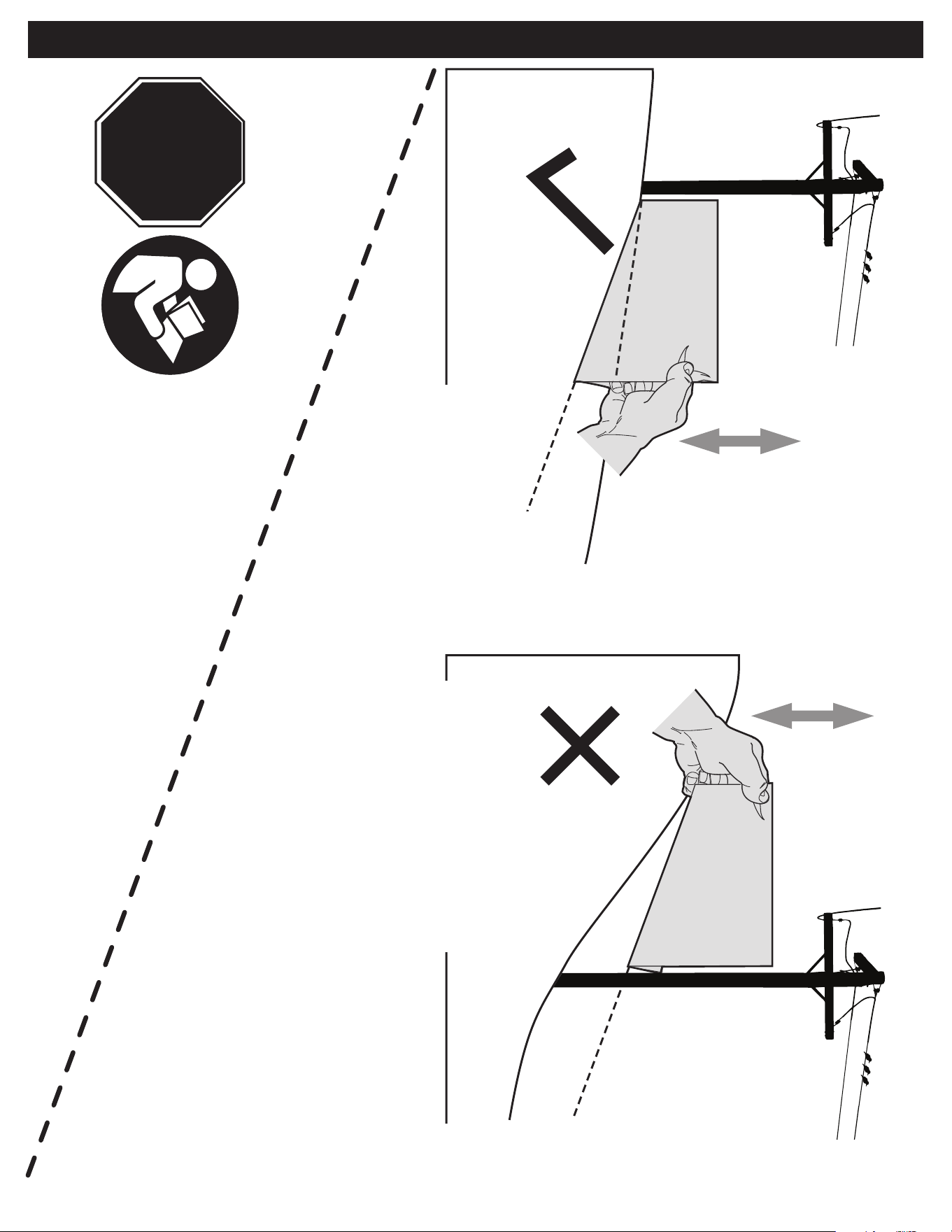
SLOPE GAUGE (INDICADOR DE PENDIENTE)
OK
20°/35% SLOPE
(PENDIENTE DE 20°/35%)
(PENTE DE 20°/35 %)
20°/35% DASHED LINE
(LÍNEA DE GUIONES A 20°/35%)
(PENTE DE 20°/35 %)
ST
OP
20°/35% SLOPE
(PENDIENTE DE 20°/35%)
(PENTE DE 20°/35 %)
TOO STEEP
(DEMASIADO EMPINADA)
(PENTE TROP RAIDE)
ST
OP