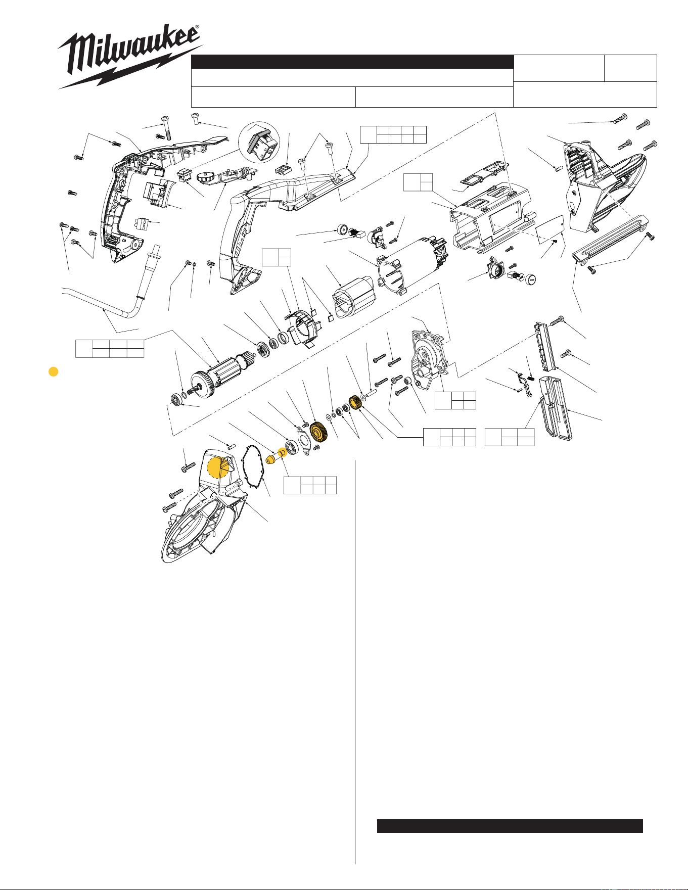
CATALOG NO. 6232-20
REVISED BULLETIN
SPECIFY CATALOG NO. AND SERIAL NO. WHEN ORDERING PARTS
DEEP CUT BANDSAW
STARTING
SERIAL NO.
DATE
Apr. 2015
WIRING INSTRUCTION
See Page 4 thru 7
MILWAUKEE ELECTRIC TOOL CORPORATION
13135 W. Lisbon Road, Brookfi eld, WI 53005
Drwg. 4
BULLETIN NO.
54-40-6240
SERVICE PARTS LIST
D51A
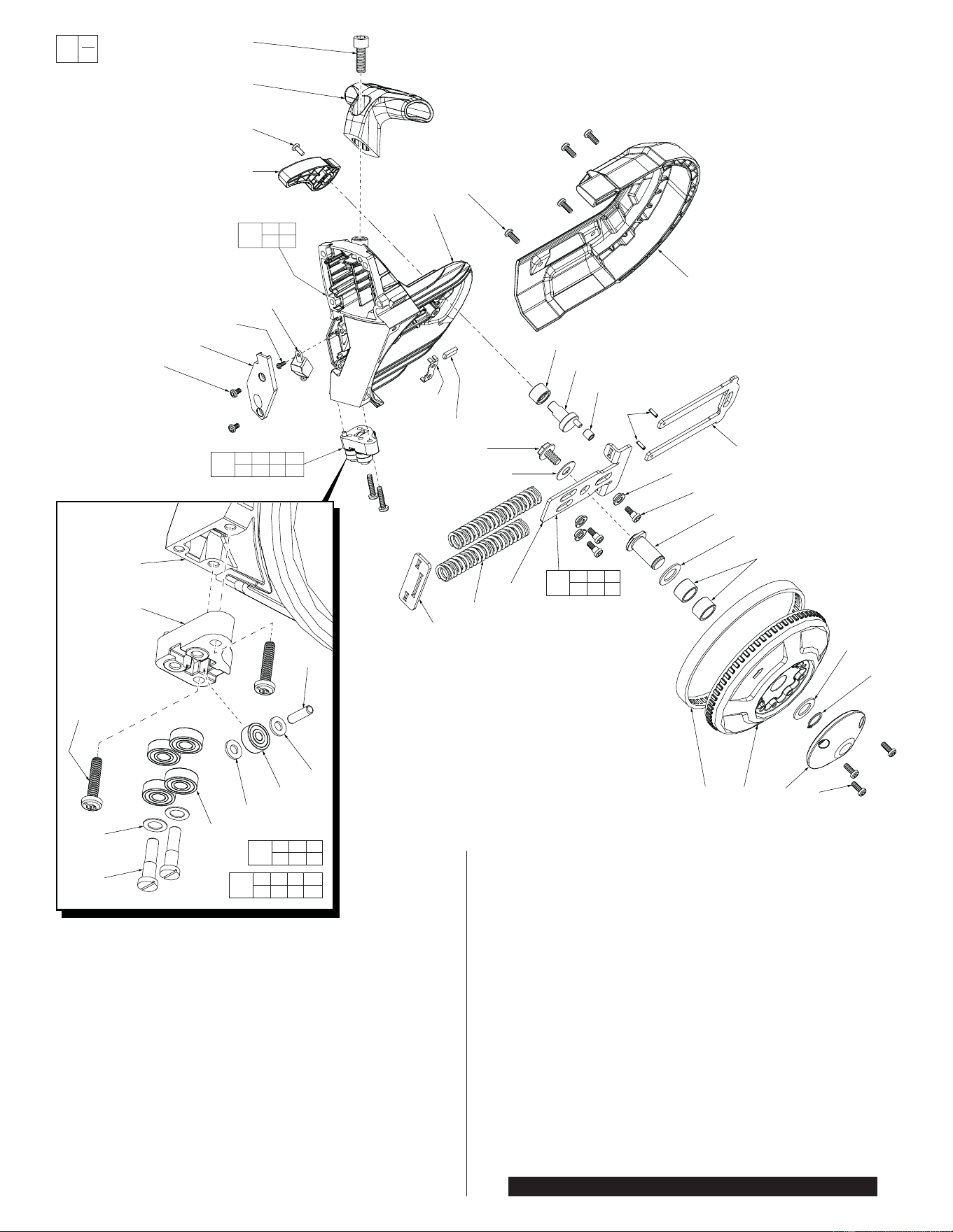
LUBRICATION NOTES:
Type ‘J’ Grease,
No. 49-08-4220
When replacing Idler
Gear Kit (145), place 4 g,
(.14 oz.) of grease around
gear teeth and ID of Idler
Gear (38).
When replacing Bevel
Pinion Assembly (133),
place 3.8 g, (.13 oz.) grease
around Helical Gear (35).
Coat teeth and end of
Bevel Pinion (30).
Place a heavy coating
of grease in the bevel
pinion bore of
Gearcase (26).
43
13
110
112
109
108
44
45
111
107
104
70
69
29
75
27
27
29
28
26
30
31
32
25
35
42
41
33 36
38
39
40
37
22
105
103
102
81
117
116
113
115
114
118
119
89 88
1
1
24
25
46
1
47
48
54
55
60
59
58
61
62
61
68
106
34
22 40
42 43
129
81 116
117 118
135
44
45
130
29
70
146
49
1 47 58 59
60 61 68
138
13 108 109
110 112
132
25 30 31
32 35
133
33 34 36
38 39
145
FIG. PART NO. DESCRIPTION OF PART NO. REQ.
1 06-82-5314 10-24 x 1/2" Pan Hd. Tapt. T-25 (5 of 23) (23)
13 45-88-0406 Washer (1 of 2) (2)
22 --------------- Needle Bearing (1 of 3) (3)
24 05-90-0225 Washer (1)
25 06-82-8828 8-32 x .313" Pan Hd. Taptite T-20 (3)
26 --------------- Gearcase (See Page 3) (1)
27 06-82-5376 12-24 x 1" Pan Hd. Taptite T-27 (7)
28 34-40-0185 Seal Gasket (1)
29 --------------- Pin (2)
30 --------------- Bevel Pinion (1)
31 --------------- Ball Bearing (1)
32 --------------- Bearing Plate (1)
33 45-88-0895 Washer (1)
34 45-88-6230 Spring Washer (1)
35 --------------- Helical Gear (1)
36 --------------- Ball Bearing (2)
37 06-82-5358 12-24 x 3/4" Pan Hd. Taptite T-27 (1)
38 --------------- Idler Gear (1)
39 45-88-6232 Washer (1)
40 --------------- Pin (1)
41 06-82-7326 8-16 x 1" Pan Hd. Plastite T-20 (4)
42 --------------- Diaphragm (1)
43 02-04-0175 Ball Bearing (1 of 2) (2)
44 --------------- Baffl e (1)
45 42-28-0085 Rubber Block (2)
46 22-64-0440 Power Cord (1)
47 06-82-7409 8-16 x 1/2" Pan Hd. Plastite T-20 (2)
48 22-56-0470 Terminal Block (1)
49 42-38-0085 Rubber Switch Cover (1)
50 23-94-0405 Leadwire Assembly-Black (Not Shown) (1)
51 23-94-0435 Leadwire Assembly-White (Not Shown) (1)
52 23-94-0440 Leadwire Assembly-Red (Not Shown) (1)
FIG. PART NO. DESCRIPTION OF PART NO. REQ.
54 23-66-0645 On-Off Switch (1)
55 23-66-1045 LED Switch (1)
58 06-82-7270 8-16 x 5/8" Pan Hd. Plastite T-20 (4)
59 06-82-0125 1/4-20 x 1.65" Pan Hd. Taptite T-30 (1)
60 --------------- Handle Cover (1)
61 06-82-5360 1/4-2 x 5/8" Pan Hd. Taptite T-30 (3)
62 14-20-0105 PCB Assembly (1)
68 --------------- Support Handle (1)
69 23-16-0015 Isolator Support (1)
70 28-50-0045 Outer Motor Housing (1)
75 --------------- Pulley Support (See Page 2) (1)
81 06-65-0115 Coiled Pin (1 of 3) (3)
88 12-20-6232 Service Nameplate (1)
89 --------------- Nameplate Screw (2)
102 23-44-0220 Brush Cap (2)
103 22-18-0025 Carbon Brush (2)
104 05-88-1360 M4 x 13.5mm ST Screw (4)
105 22-20-0080 Brush Holder Assembly (2)
106 14-20-0195 Sensor Assembly (1)
107 31-50-0305 Inner Motor Housing (1)
108 42-96-0016 Bearing Cap (1)
109 02-04-0645 Ball Bearing (1)
110 23-38-0030 Magnetic Ring (1)
111 18-07-0025 Service Field Kit (1)
112 --------------- Armature (1)
113 06-82-0065 10-32 x 1" Pan Hd. Taptite T-25 (1)
114 30-13-0015 T-Block (1)
115 06-82-5330 10-32 x 5/8" Pan Hd. Taptite T-25 (1)
116 40-50-0845 Lever Release Spring (1)
117 42-42-0060 Release Button (1)
118 --------------- Shoe Bumper (1)
119 43-54-0085 Blade Guard (1)
129 14-13-0010 Diaphragm Kit (1)
130 42-14-0015 Fan Baffl e Kit (1)
132 16-10-0025 Service Armature Kit (1)
133 32-60-0095 Bevel Pinion Assembly (1)
135 42-18-0035 Shoe Bumper Kit (1)
138 31-44-0745 Handle Assembly Kit (1)
145 32-60-6230 Idler Gear Kit (1)
146 14-30-6230 Outer Motor Housing Kit (1)
SEE PAGE 3 FOR FASTENER TORQUE CHART
Apply Loctite
®
243
to threads of
screws 113
and 115.
83
84
85
93
94
91
77
78
81
84
87
8 86 2 1
98
97
96
80
79
82
90
75
71
100
101
99
1
76
73
74
147
72
75
92
20
15
14
16
17
18
17
19
95
75 90
91
142
81 82 96
97 98
139
14 15 16
17 18 19
136
14 15 16 17
18 19 20 92
134
14 15 16 17
18 19 20 92
134
FIG. PART NO. DESCRIPTION OF PART NO. REQ.
1 06-82-5314 10-24 x 1/2" Pan Hd. Tapt. T-25 (7 of 23) (23)
2 31-15-0325 Pulley Cover (1 of 2) (2)
8 45-69-0010 Pulley Tire (1 of 2) (2)
14 --------------- 12-24 UNC x .96" Slotted (2 of 4) (4)
15 --------------- Washer (2 of 4) (4)
16 --------------- Ball Bearing (4 of 8) (8)
17 --------------- Washer (2 of 4) (4)
18 --------------- Ball Bearing (1 of 2) (2)
19 --------------- Pin (1 of 2) (2)
20 06-82-5574 10-24 x 7/8" Pan Hd. Tapt. T-25 (2 of 4) (4)
71 06-82-7252 8-32 x .38" Pan Hd. Taptite T-20 (2)
72 31-52-0066 Tension Release Lever (1)
73 06-75-4675 3/8"-16 UNC x 1" Socket Hd. Cap Screw (1)
74 31-44-0740 Front T-Handle (1)
75 --------------- Pulley Support (1)
76 31-15-0335 Front Pulley Shroud (1)
77 45-08-0070 Cam Shaft (1)
78 42-40-0105 Cam Bushing (1)
79 06-75-0035 5/16-18 x 9/16" Screw (1)
80 45-88-0395 Washer (1)
FIG. PART NO. DESCRIPTION OF PART NO. REQ.
81 06-65-0115 Coil Pin (2 of 3) (3)
82 --------------- Driver Plate (1)
83 42-12-0010 Front Pulley Shaft (1)
84 45-88-7165 Washer (2)
85 42-40-0580 Sleeve Bearing (2)
86 28-95-0050 Front Pulley (1)
87 34-60-1400 Snap Ring (1)
90 44-52-0120 Blade Backing Pad (1)
91 02-50-0035 Needle Bearing (1)
92 --------------- Front Roller Block (1)
93 06-81-0075 Shoulder Screw (3)
94 42-40-0115 Tension Bushing (3)
95 44-66-6232 Wear Plate (1)
96 --------------- Support Plate (1)
97 --------------- Blade Tension Spring (2)
98 --------------- Contact Plate (1)
99 14-20-0115 LED Assembly (1)
100 05-81-0010 M3 x 8mm Screw (1)
101 31-15-0345 LED Cover (1)
134 42-24-0015 Front Guide Roller Kit (1)
136 14-46-0465 Guide Roller Kit (1)
139 42-18-0015 Tensioning Mechanism Assembly (1)
142 14-30-0060 Pulley Support Kit (1)
147 06-82-0145 8-32 x .48" Pan Hd. M Screw T-20 (1)
SEE PAGE 3 FOR FASTENER TORQUE CHART
EXAMPLE:
Component Parts
(Small #) Are Included
When Ordering The
Assembly (Large #).
0
00
FIG. NOTE:
75,90 Use Loctite
®
326 or the equivalent
to secure the Blade Backing Pad (90)
to the Pulley Support (75).
FIG. NOTE:
73 Use Loctite
®
243 or the equivalent
to the threads of Screw (73) prior
to installing T-Handle (74) onto
Pulley Support (75).
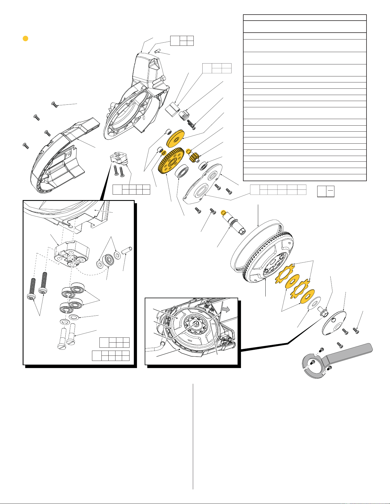
FIG. PART NO. DESCRIPTION OF PART NO. REQ.
1 06-82-5314 10-24 x 1/2" Pan Hd. Tapt. T25 (11 of 23) (23)
2 31-15-0325 Pulley Cover (1 of 2) (2)
3 06-75-0010 M Screw, 3/8"-16 UNC 5/8" Hex Hd. (1)
4 40-50-0805 Disc Spring (1)
5 43-06-0010 Clutch Washer (2)
6 43-06-0015 Clutch Plate (2)
7 28-95-0040 Rear Pulley (1)
8 45-69-0010 Pulley Tire (1 of 2) (2)
9 --------------- Spindle (1)
10 --------------- Gearcase Cover (1)
11 --------------- Ball Bearing (1)
12 --------------- Spur Gear (1)
13 45-88-0406 Washer (1 of 2) (2)
14 --------------- 12-24 UNC x .96" Slotted (2 of 4) (4)
15 --------------- Washer (2 of 4) (4)
16 --------------- Ball Bearing (4 of 8) (8)
17 --------------- Washer (2 of 4) (4)
18 --------------- Ball Bearing (1 of 2) (2)
19 --------------- Pin (1 of 2) (2)
20 06-82-5574 10-24 x 7/8" Pan Hd. Tapt. T-25 (2 of 4) (4)
LUBRICATION NOTES:
Type ‘J’ Grease, No. 49-08-4220
When installing Gearcase Cover Kit (126),
place 4.8 g, (.16 oz) grease to the Bevel
Gear (120). Place 6 g (.21 oz.) to the large
Spur Gear (12). Coat all of the gear teeth
on small Spur Gear (121) with grease.
Coat Washer (13) and ends of shafts
(9 & 122) with J Grease.
Lightly coat both sides of
Washers (5) and Clutch
Plates (6) with J Grease.
18
19
17
21
26
1
23
1
2
3
4
5
6
7
8
9
1
10
11
12
13
22
123
29
26
14
15
16
20
22 26
29
128
14 15 16
17 18 19
136
14 15 16 17
18 19 20 21
127
123 124
125
137
14 15 16 17
18 19 20 21
127
9 10 11 12 13
43 120 121 122
126
124
125
120
122
121
43
7
8
3
26
Dowel
To properly tighten
hex head screw (3), use
a wooden dowel or a nylon
rod in the opening between
the rear pulley (7) and gearcase
(26). Be careful not to damage
pulley tire (8). Apply enough pressure
to prevent rear pulley from turning.
Torque hex head screw (3) to 312 in/lbs.
Service Tool 61-30-6232 can be ordered
to secure rear pulley to tighten hex hd. screw.
Service Tool
61-30-6232
Use screws (1) to temp-
orarily attach service
tool to rear pulley. Hold
tool and tighted hex
head screw (3) to 312 in/lbs.
FIG. PART NO. DESCRIPTION OF PART NO. REQ.
21 --------------- Rear Roller Block (1)
22 --------------- Needle Bearing (2 of 3) (3)
23 31-15-0330 Rear Pulley Shroud (1)
26 --------------- Gearcase (1)
29 --------------- Pin (1 of 2) (2)
43 02-04-0175 Ball Bearing (1 of 2) (2)
120 --------------- Bevel Gear (1)
121 --------------- Spur Gear (1)
122 --------------- Shaft (1)
123 --------------- Tire Cleaning Brush (1)
124 --------------- Tire Cleaning Brush Cover (1)
125 06-82-5346 8-32 x 3/4" Pan Hd. Taptite T-20 (2)
126 14-30-0010 Gearcase Cover Kit (1)
127 42-28-0025 Rear Guide Roller Kit (1)
128 14-30-0015 Gearcase Top Assembly (1)
136 14-46-0465 Guide Roller Kit (1)
137 44-60-0295 Tire Clearing Brush Kit (1)
42-55-6232 Blow Molded Carrying Case (Not Shown) (1)
EXAMPLE:
Component Parts
(Small #) Are Included
When Ordering The
Assembly (Large #).
0
00
NOTE:
312 in/lbs.
or 26 ft/lbs.
SCREW TORQUE CHART
Torque
Fig. Part No. Location (In/Lbs.)
3 06-75-0010 Rear Pulley 312
20 06-82-5574 Front Roller Block
Rear Roller Block 39
25 06-82-8828 Bearing Plate
Ground Terminal 17
27 06-82-5376 Gearcase
Pulley Support 38
37 06-82-5358 Diaphragm 38
41 06-82-7326 Diaphragm 16
47 06-82-7409 Handle Cover 17
58 06-82-7270 Handle Cover 17
59 06-82-0125 Handle Cover 39
61 06-82-5360 Handle Cover
Support Handle 39
71 06-82-7252 LED Cover 22
73 06-75-4675 Front T-Handle 83
79 06-75-0035 Support Plate 104
93 06-81-0075 Support Plate 36
100 05-81-0010 LED Assembly 6
104 05-88-1360 Brush Holder Assembly 5
113 06-82-0065 T-Block 19
115 06-82-5330 T-Block 19
125 06-82-5346
Tire Cleaning Brush Cover
22
147 06-82-0145 Tension Release Lever 22
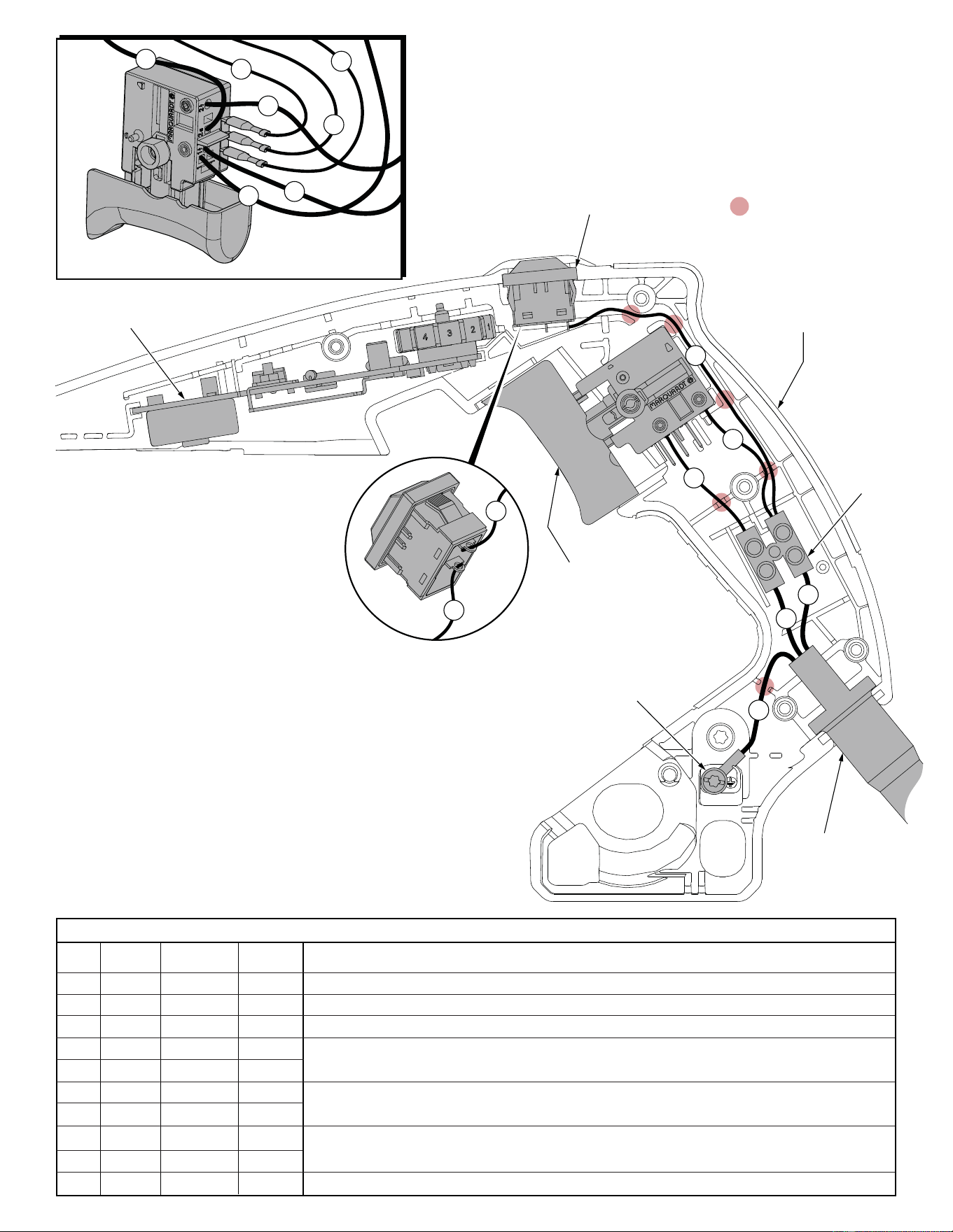
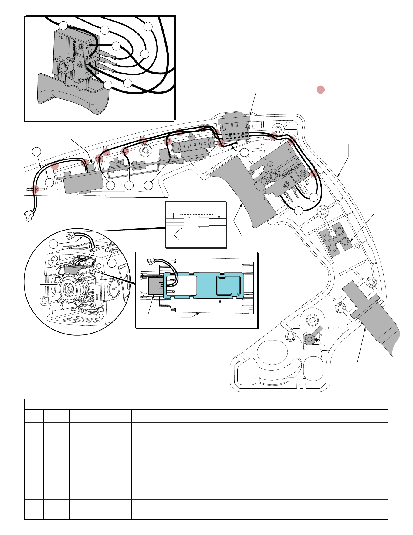
WIRING SPECIFICATIONS
= WIRE TRAPS
or GUIDES
4
9
8
10
7
5
11
SWITCH
WIRING DETAIL
2
1
4
3
25
LED Switch
PCB Assembly
On-Off Switch
Ground Screw
Terminal
Block
(T1)
Power Cord
Support Handle
5
25
6
Terminals, Connectors and 1 or 2 End Wire Preparation
Wire
Color
Origin or
Gauge
Wire
No.
Length
AS AN AID TO REASSEMBLY, TAKE NOTICE OF WIRE ROUTING AND
POSITION IN WIRE GUIDES AND TRAPS WHILE DISMANTLING TOOL.
BE CAREFUL AND AVOID PINCHING WIRES BETWEEN HANDLE
HALVES WHEN ASSEMBLING.
1 Black Cord ----- Component of the cord set. Connect to lower right of terminal block (T1).
2 White Cord ----- Component of the cord set. Connect to lower left of terminal block (T1).
3 Green Cord ----- Component of the cord set. Connect to grounding area on surface of gearcase.
4 Black 23-94-0405 ----- Leadwire assembly. On one end twist strands together with red wire #25 and connect with the
upper right of terminal block (T1). Connect the other end to the '2' position of the switch.
5 White 23-94-0435 ----- Leadwire assembly. Connect one end to the upper left of terminal block (T1). Connect the
other end to the '1' position of the switch.
25 Red 23-94-0440 ----- Leadwire assembly. On one end twist strands together with black wire #4 and connect with the
upper right of terminal block (T1). Solder other end to position '1' on LED switch.
Route red leadwire assembly #25
from terminal block (T1) to the
LED switch as shown. Solder
to post marked '1' on LED switch.
Black wire #6 from the PCBA is to
be soldered to the post marked '2'
on the LED switch. See page 6
for wire routing and placement of
wire #6 in traps of support housing.
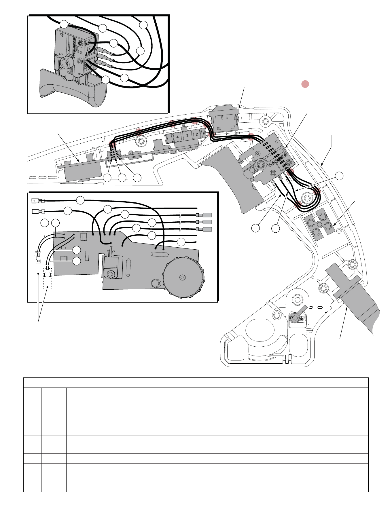
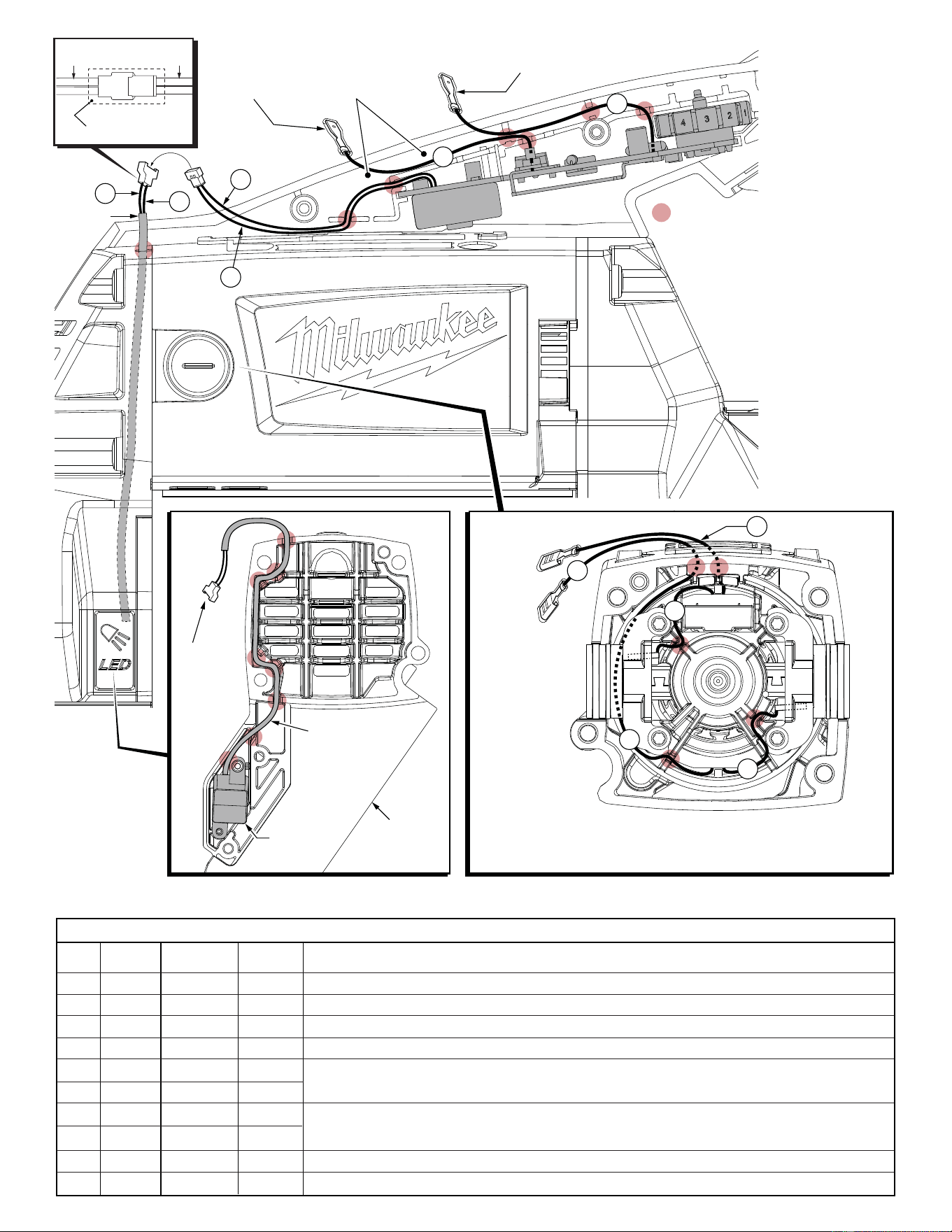
= WIRE TRAPS
or GUIDES
9
8
10
7
6
11
PCB ASSEMBLY
WIRING DETAIL
13
12
19
20
17
18
4
9
8
10
7
5
11
SWITCH
WIRING DETAIL
LED Switch
PCB Assembly
On-Off Switch
Terminal
Block
(T1)
Power Cord
Support Handle
11
9
10
10
9
11
Heat Shrink Tube
No. 23-82-0400 (2 places)
Place over connected wires 17 and 18 from PCB
Assembly and wires 23 and 24 of Sensor Assembly.
Heat over the joined connectors. (See page 6).
Place over connected wires 19 and 20 from PCB
Assembly and wires 21 and 22 of LED Assembly.
Heat over the joined connectors. (See page 7).
9 Red 14-20-0105 ----- Component of the PCB Assembly. Connect to the '2a' position on the on-off switch.
10 White 14-20-0105 ----- Component of the PCB Assembly. Connect to the '1' position on the on-off switch.
11 Black 14-20-0105 ----- Component of the PCB Assembly. Connect to the '2' position on the on-off switch.
WIRING SPECIFICATIONS
Terminals, Connectors and 1 or 2 End Wire Preparation
Wire
Color
Origin or
Gauge
Wire
No.
Length
AS AN AID TO REASSEMBLY, TAKE NOTICE OF WIRE ROUTING AND
POSITION IN WIRE GUIDES AND TRAPS WHILE DISMANTLING TOOL.
BE CAREFUL AND AVOID PINCHING WIRES BETWEEN HANDLE
HALVES WHEN ASSEMBLING.
= WIRE TRAPS
or GUIDES
4
9
8
10
7
5
11
SWITCH
WIRING DETAIL
23
24
Sensor
Assy.
LED Switch
PCB Assembly
On-Off Switch
Terminal
Block
(T1)
Power Cord
Support Handle
7
17
8
7
6
8
6
18
Female connector with wires 17 and 18 from the
PCB Assembly is to be joined with male connentor
of the sensor assembly (wires 23 and 24).
See detail wiring below.
Sensor
Assy. Insulator Support
Inner
Motor Housing
Top View shown without Outer Motor Housing
Route sensor assembly wires through the
center slot of the inner motor housing.
Note: Field wire 15 will also utilize
the same center slot.
Heat Shrink Tube
No. 23-82-0400
Wires
17 & 18
Wires
23 & 24
6 Black 14-20-0105 ----- Component of the PCB Assembly. Solder to position '2' on LED switch.
7 White 14-20-0105 ----- Component of the PCB Assembly. Connect to position '1' at the on-off switch.
8 Black 14-20-0105 ----- Component of the PCB Assembly. Connect to position '1' at the on-off switch.
17 Black 14-20-0105 ----- Components of the PCB Assy. Wires 17 and 18 are joined together with a female connector.
18 White 14-20-0105 ----- The female connector is to connect with the male terminal of sensor assembly 14-20-0195.
23 Red 14-20-0195 ----- Components of the Sensor Assy. Wires 23 and 24 are joined together with a male connector.
24 White 14-20-0195 ----- The male connector is to connect with female terminal of wires 17 and 18.
WIRING SPECIFICATIONS
Terminals, Connectors and 1 or 2 End Wire Preparation
Wire
Color
Origin or
Gauge
Wire
No.
Length
= WIRE TRAPS
or GUIDES
19
20
21
22
Insulating
Sleeve
13
12
Connect male terminal of wire 13 with
female terminal of field wire 15
Connect male
terminal of wire
12 with female
terminal of field
wire 14
Place connected
terminals of wires
12 & 14 and
13 & 15 here.
Insulating
Sleeve
LED
Assembly
Pulley
Support
Connect
to male
terminal
with wires
19 and 20
from PCBA
BACK VIEW (INSIDE) OF PULLEY SUPPORT FRONT VIEW (BRUSH END) OF OUTSIDE MOTOR HOUSING
15
14
14
26
27
Left
Brush
Right
Brush
Route black field
lead #14 around
the outside of
the inner motor
housing, trapping the
wire in the outside slot
at the top. Route #14
out the insulator
support and connect
with blue wire #12 of the PCBA. Trap black field lead #15 in the center
slot of the inner motor housing and route out the insulator support and
connect with red wire #13 of the PCBA. Route and trap white field leads
as shown and connect to brush holder assemblies.
Connect to red #13
on PCBA
Connect to
blue #12
on PCBA
Heat Shrink Tube
No. 23-82-0400
Wires
21 & 22
Wires
19 & 20
12 Blue 14-20-0105 ----- Component of PCB Assembly. Connect male terminal with female terminal of wire 14.
13 Red 14-20-0105 ----- Component of PCB Assembly. Connect male terminal with female terminal of wire 15.
14 Black 18-07-0025 ----- Component of the fi eld. Connect female terminal to the male terminal of blue wire #12.
15 Black 18-07-0025 ----- Component of the fi eld. Connect female terminal to the male terminal of red wire #13.
19 Black 14-20-0105 ----- Components of PCB Assembly. Wires 19 and 20 are joined together with a male terminal.
20 White 14-20-0105 ----- Connect the male terminal to the female terminal of wires 21 and 22 of the LED assembly.
21 Black 14-20-0115 ----- Components of the LED assy. Wires 21 and 22 are joined together with a female terminal.
22 White 14-20-0115 ----- Connect the female terminal to the male terminal of wires 19 and 20 of the PCB Assembly.
26 White 18-07-0025 ----- Component of the fi eld. From top of fi eld, connect to the right brush holder tab.
27 White 18-07-0025 ----- Component of the fi eld. From bottom of fi eld, connect to the left brush holder tab.