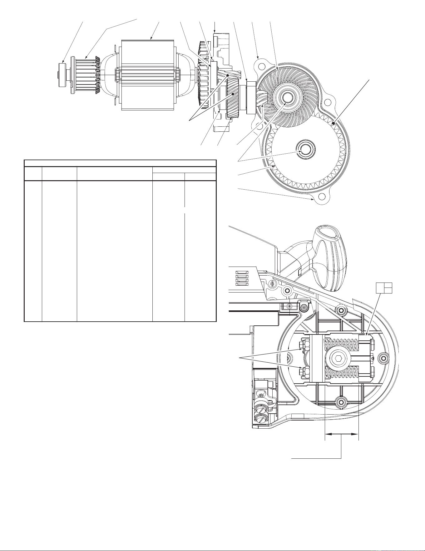
GEAR ASSEMBLIES
#105 & #106 MUST BE
ORDERED AS A SET
CAT. NO. 32-05-6242
36 (3X)
57 58
59 60
105
62
63
108
61
64
106
67 68
70 71
107
66
(4x)
20 39
66
96
88
65
82
83
89
(2x)
90
(2x)
73
63
75
74
(8x)
74
(6x)
77
110
86
91
60
62
71
70
72
67
62
61
64
68
69
35
(4x)
58
59
57
56
55
(3x)
111
76
52
47(2x)
48(2x)
49(2x)
112
50
35(3x) 3951
85 84
81
53 (4x) 99
79
109
87
78
66
91
95
75
86
94
53
80
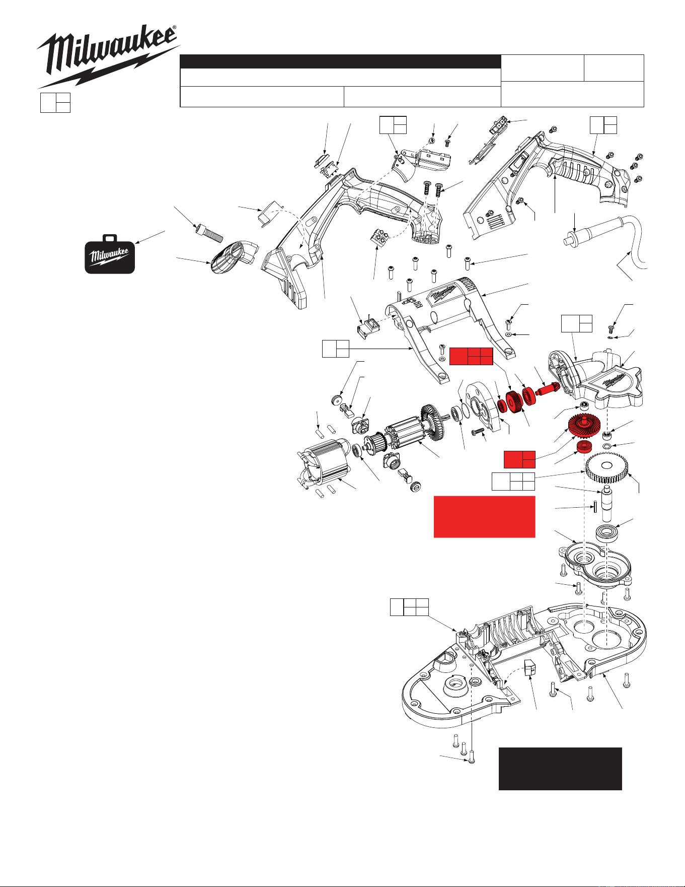
AC COMPACT BAND SAW
6242-6
C13B
54-40-6201
58-01-6200
Jan. 2014
REVISED BULLETIN
54-40-6200
SERVICE PARTS LIST
BULLETIN NO.
WIRING INSTRUCTION
DATE
SPECIFY CATALOG NO. AND SERIAL NO. WHEN ORDERING PARTS
CATALOG NO.
MILWAUKEE ELECTRIC TOOL CORPORATION
13135 W. LISBON RD., BROOKFIELD, WI 53005
Drwg. 4
STARTING
SERIAL NO.
EXAMPLE:
Component Parts (Small #)
Are Included When Ordering
The Assembly (Large #).
0
00
SEE ADJACENT PAGES
FOR ADDITIONAL
SERVICE NOTES AND
LUBRICATION
FIG. PART NO. DESCRIPTION OF PART NO. REQ.
35 06-82-5574 10-24 x 7/8" Pan Hd. Tapt. T-25 Screw (7)
36 06-82-0035 M5 Pan Hd. T-20 Screw (3)
39 --------------- Deck (1)
47 23-44-0025 Brush Cap (2)
48 22-20-0070 Brush Tube Assembly (2)
49 22-18-0020 Carbon Brush Assembly (2)
50 18-07-2000 Service Field (1)
51 14-20-0175 LED with Box Assembly (1)
52 16-07-2000 Service Armature (1)
53 05-78-0305 Switch Screw (4)
55 06-82-5320 8-32 x 5/8" Pan Hd. Slt. Tapt. T-20 Screw (3)
56 28-28-0080 Diaphragm (1)
57 02-04-0645 Ball Bearing (1)
58 --------------- 1st Gear (1)
59 --------------- Ball Bearing (1)
60 --------------- 2nd Bevel Pinion (1)
61 --------------- Bevel/Spur Gear (1)
62 --------------- Needle Bearing (2)
63 --------------- Gearcase (1)
64 02-04-0135 Ball Bearing (1)
65 22-64-0485 Cord (1)
66 45-30-0025 Rubber Slug (4)
67 --------------- 3rd Gear (1)
68 --------------- Pulley Shaft (1)
69 43-96-0105 Key (1)
70 02-04-1525 Ball Bearing (1)
71 45-88-0406 Washer (1)
72 28-14-0180 Bearing Plate Bottom (1)
73 44-76-0210 Cord Protector (1)
74 06-82-7270 8-16 x 5/8" Pan Hd. Slt. Plast. T-20 Screw (14)
75 --------------- Handle - Left (1)
76 02-04-0175 Ball Bearing (1)
77 22-56-0475 Terminal Block (1)
78 42-55-0110 Carrying Case (1)
79 06-82-5294 1/4-20 x 3/4" Pan Hd. Tapt. T-30 Screw (2)
80 23-66-0395 Switch (1)
81 06-82-7251 8-16 x 3/8" Pan Hd. Slt. Plast. T-20 Screw (1)
82 06-82-8828 8-32 x 5/16" Pan Hd. Tapt. T-20 Screw (1)
83 05-90-0225 Washer (1)
84 23-66-1045 LED Switch (1)
85 42-38-0085 Soft Cover (1)
86 --------------- Handle - Right (1)
87 06-82-0045 3/8"-16 UNC-3A Hex Recess Screw (1)
88 31-44-0095 Front T-Handle (1)
89 06-82-5316 8-32 x 1/2" Pan Hd. Slt. Tapt. T-20 Screw (2)
90 45-88-0825 Washer (2)
91 --------------- Motor Cover (1)
94 31-44-0285 Handle Kit (1)
95 31-15-0195 Motor Cover Assembly (1)
96 28-90-0010 Deck Assembly (1)
99 14-20-0145 Main PCBA (1)
107 14-73-0040 Pulley Gear Assembly (1)
108 14-30-0050 Top Gearcase Assembly (1)
109 14-20-0155 LED Driver PCBA (1)
110 14-20-0165 Sensor PCBA (1)
111 34-40-0205 O-Ring (1)
112 02-04-0170 Ball Bearing (1)
23-94-0060 Black Leadwire Assy. -
To #77 & #80 (Not Shown)
(1)
23-94-0065 White Leadwire Assy. -
To #77 & #80 (Not Shown)
(1)
23-94-0080 Red Leadwire Assy. -
To #84 & #80 (Not Shown)
(1)
23-94-0085 Red Leadwire Assy. -
To #48 (Top Brush) &
connector on #99 (Not Shown)
(1)
FIG. NOTE:
64,70 Orient the Ball Bearings so the seal faces the gears.
68 Apply approximately .1g Loctite
®
C5-A Copper
Anti-Seize (or equivalent) to bottom portion
of Pulley Shaft that fi ts into Rear Pulley (4).
}
SEE SERVICE WIRING
DIAGRAM 58-01-6200
105 Bevel Pinion Assembly (1)
106 Bevel/Spur Gear Assy. (1)
ORDER AS A SET
Cat. No. 32-05-6242
}
46
45
40
42
43
5
4
3
15
2
1
39
25
24
34 (9x)
33
29 (4X)
30 (2X)
31 (2X)
27 28
26 11
32
11
29 (4X)
31 (2X)
27 28
26 (2X)
30 (2X)
41 44
45 46
104
11 26 27 28 29
30 31 33 89 90
101
11 26 27 28 29
30 31 32 89 90
102
20 39
66
96
37
38
103
12
98
9
10
97
26 27 28
29 30 31
100
16
18
7 13 14
15 16 18
10
7
13
14
11
22
23
21
49
12
21 22
23 49
113
44
41
38
37
20
19
17
9
8
5
6
3
5
2
1
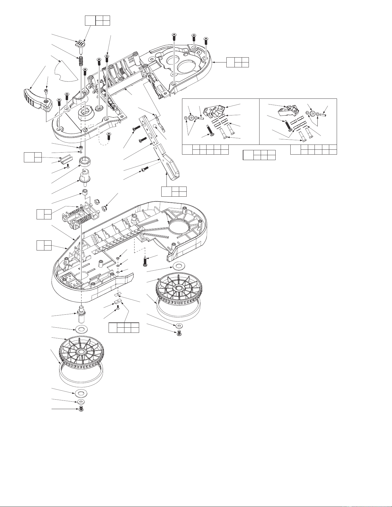
FIG. PART NO. DESCRIPTION OF PART NO. REQ.
1 06-82-0040 1/4"-20 UNC-2A TH Hex Screw (2)
2 45-88-0832 Steel Washer (2)
3 45-69-0030 Pulley Tire (2)
4 44-77-0170 Rear Pulley (1)
5 45-88-0545 Plastic Washer (3)
6 28-95-0030 Front Pulley Assembly (1)
7 --------------- Nut (1)
8 42-12-0235 Front Pulley Axle (1)
9 --------------- Guard (1)
10 14-46-0342 Blade Backing Pad Kit (1)
11 05-88-9915 M5 x 25mm DG Pan Hd. T-25 Screw (3)
12 06-57-5000 Nut (2)
13 --------------- Spring Washer (1)
14 --------------- Washer (1)
15 --------------- Insulator (1)
16 --------------- Blade Backing Pad (1)
17 42-40-1010 Bushing (1)
18 --------------- Screw (1)
19 45-08-0065 Blade Release Shaft Assembly (1)
20 42-40-0640 Sleeve Bearing (1)
21 --------------- Bumper (1)
22 06-82-0050 M5.0 x 0.8-6g Flat Hd. T-20 Screw (2)
23 --------------- T-Block (1)
24 02-02-0250 1/4" Steel Ball (1)
25 40-50-0655 Bumper Spring (1)
26 --------------- Washer (4)
27 --------------- Ball Bearing (2)
28 --------------- Pin (2)
29 --------------- Ball Bearing (8)
30 --------------- Washer (4)
31 --------------- #12-24 UNC-2A CH Slt. Screw (4)
32 --------------- Rear Blade Guide Block (1)
33 --------------- Front Blade Guide Block (1)
34 06-82-0030 M4.5 Flat Hd. T-20 Screw (9)
37 --------------- M3.0 Flat Hd. B Screw (1)
38 --------------- Guide Plate (1)
39 --------------- Deck (1)
40 12-20-2629 Service Nameplate Kit (1)
41 --------------- M2.0 x .25 PWH T-6 Screw (1)
42 45-08-0490 Blade Release Lever (1)
43 06-82-7252 8-32 x 3/8" Pan Hd. Slt. Tapt. T-20 Screw (1)
44 --------------- Bushing (1)
45 --------------- Spring (1)
46 --------------- Blade Ejection Pin (1)
49 --------------- Bandsaw Fixed Material Guide w/ Screw (1)
96 28-90-0010 Deck Assembly (1)
97 28-41-0052 Guard Assembly (1)
98 42-18-0025 Blade Tension Bar Assembly (1)
100 14-46-0465 Guide Block Hardware Kit (1)
101 42-28-0410 Front Guide Block Assembly (1)
102 42-28-0420 Rear Guide Block Assembly (1)
103 44-66-0325 Guide Plate Kit (1)
104 44-60-0240 Blade Ejection Shaft Kit (1)
113 42-38-0010 Bumper Assembly (1)
FIG. NOTE:
24 Apply Loctite
®
Silver Grade Anti-Seize Stick 80209 (or equivalent) to Steel Ball.
8 Apply Loctite
®
Cleaner 755 (or equivalent) to Front Pulley Axle thread fi rst then
place a drop or two of Blue Loctite
®
443 (or equivalent) to axle threads.
18,41 Apply a drop of Blue Loctite
®
443 (or equivalent) to threads of each screw.
9,38 Apply Loctite
®
C5-A Copper Anti-Seize (or equivalent) to metal insert in Guard
and to Guide Plate. Approximately .1g for each part.
= Part number change
from previous
service parts list.
* No. 14-46-0715
Band saw shim service kit
available, not shown
52 50 76 111 56 59 72 61
LUBRICATION:
Use Type ‘J’ Grease, No. 49-08-4220
Place approx. 1.75 oz. (5 gm) of grease on the
2nd Bevel Pinion (60) and Bevel Spur Gear (61).
Place approx. 1.75 oz. (5 gm)
of grease on and around the
3rd Gear.
57 58 60
62
67
72
Place approx. 1.75 oz. (5 gm) of
grease on the Armature Pinion and 1st
Gear (58).
57
12
98
12
Dimension between inside edges
of blade tensioning bars:
35.8 ±0.2mm (1-13/32”)
SCREW TORQUE CHART
SEAT TORQUE
ITEM PART NO. PART DESCRIPTION (IN/LBS) (KG/CM)
1 06-82-0040 1/4"-20 UCN-2A TH Hex 65-74 75-85
7 --------------- M2 x 0.4 Nut 2-4 3-5
8 42-12-0235 Front Pulley Axle 78-87 90-100
11 05-88-9915 M5 x 25mm DG PH T-25 16-21 19-24
12 06-57-5000 Flex-Loc Nut To Assembly Length
18 --------------- M2 x 0.4 T-6 2-4 3-5
22 06-82-0050 M5 x .8-6g FH T-20 26-30 30-35
31 06-82-0120 #12-24 UNC-2A CH Slotted 39-48 45-55
34 06-82-0030 M4.5 FH T-20 16-21 19-24
35 06-82-5574 #10-24 x 7/8" PH T-25 39-48 45-55
36 06-82-0035 M5.0 PH T-20 22-26 25-30
37 06-82-0010 M3 FH B 6-9 7-10
41 06-82-0025 M2.0 x .25 PWH T-6 2-4 3-5
43 06-82-7252 #8-32 x 3/8" PH T-20 22-26 25-30
55 06-82-5320 #8-32 x 5/8" PH T-20 26-31 30-36
74 06-82-7270 #8-16 x 5/8" PH T-20 16-21 19-24
79 06-82-5294 1/4"-20 UNC-2A PH T-30 65-74 75-85
81 06-82-7251 #8-16 x 3/8" PH T-20 10-14 12-16
82 06-82-8828 T-20 Ground Screw 9-13 10-15
87 06-82-0045 3/8"-16 UNC-3A T-20 87-104 100-120
89 06-82-5316 #8-32 x 1/2" PH T-20 16-21 19-24