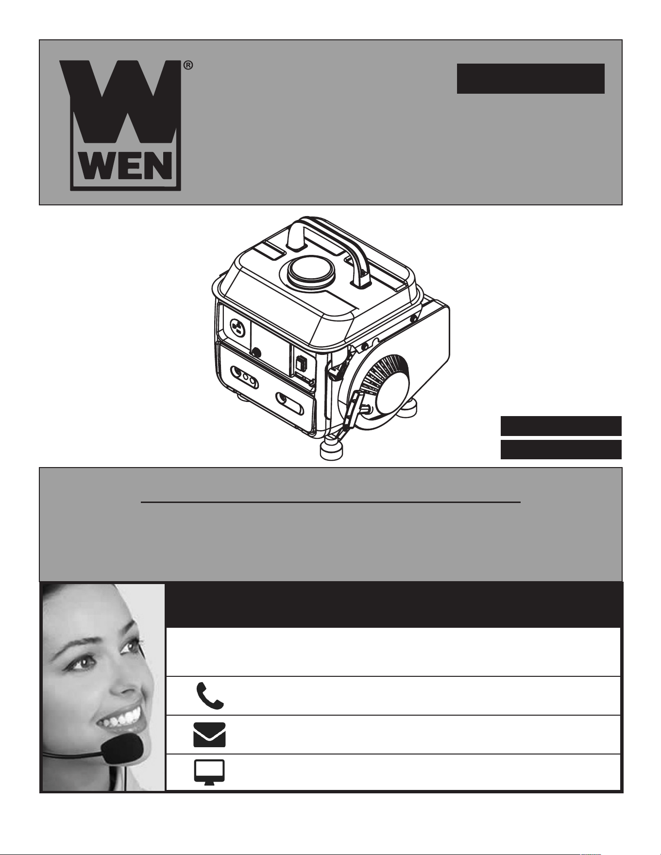
For replacement parts visit
WENPRODUCTS.COM
CARB COMPLIANT
EPA CERTIFIED
Your new tool has been engineered and manufactured to WEN’s highest standards for dependability, ease
of operation, and operator safety. When properly cared for, this product will supply you years of rugged,
trouble-free performance. Pay close attention to the rules for safe operation, warnings, and cautions. If
you use your tool properly and for its intended purpose, you will enjoy years of safe, reliable service.
IMPORTANT:
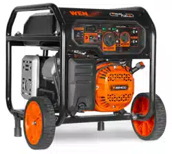
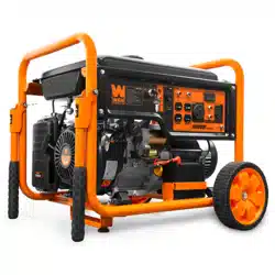
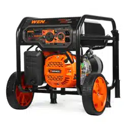
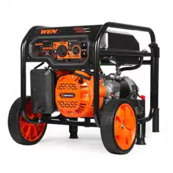
MODEL 56105
1000 WATT
2-STROKE GENERATOR
NEED HELP? CONTACT US!
800-232-1195 (M-F 8am-5pm CST)
techsupport@wenproducts.com
WENPRODUCTS.COM
Have product questions? Need technical support?
Please feel free to contact us at:
NOTICE: Please refer to wenproducts.com for the most up-to-date instruction manual.

TABLE OF CONTENTS
SPECIFICATIONS
Introduction ....................................................................................1
Safety Information ...........................................................................4
Generator Safety Warnings ..............................................................5
Unpacking & Assembly ....................................................................8
Know Your Generator .......................................................................8
Generator Preparation ...................................................................10
Starting the Generator ...................................................................12
Using the Generator ......................................................................14
Stopping the Generator .................................................................16
Maintenance .................................................................................17
Transportation & Storage ...............................................................22
Troubleshooting Guide ...................................................................23
Specifications ...............................................................................24
Wiring Diagram .............................................................................25
Exploded View & Parts List ............................................................26
Warranty Statement ......................................................................28
Wattage 900 Rated Watts, 1000 Surge Watts
Rated Output AC 120V, 60Hz, 7A
Engine 2-stroke, single cylinder, 63cc
Fuel Tank Capacity 1 gallon (4L)
Fuel Mix Ratio 50:1 (Gasoline:Oil)
Half-Load Run Time 5 hours
Full-Load Noise Rating 95 dB at 13 feet (4m)
Dimensions 15 x 12 x 14.5 in. (L x W x H)
Product Net Weight 39 lbs
2
SERIAL NUMBER
INTRODUCTION
THANKS FOR PURCHASING THE WEN GENERATOR.
Refer to the illustration below for the location of the serial number. Record the generator information in the
spaces provided below. If assistance for information or service is required, please contact the Customer
Service Help Line by calling 800-232-1195, M-F 8-5 CST; you will be asked to provide the following gen-
erator information when calling.
GENERATOR MODEL NUMBER: WEN 56105
DATE OF PURCHASE: __________________________________________
PURCHASED FROM: ___________________________________________
SERIAL NUMBER: _____________________________________________
SERVICE RECORD
Record the service dates of your generator in the chart below.
Service Record Date Date Date Date Date Date
Change Oil
Change Spark Plug
Clean Fuel Tank
Clean Air Cleaner
TO MAXIMIZE THE LIFESPAN OF YOUR GENERATOR:
We recommend running your generator at least ONCE A MONTH for 15 to 30 minutes. Start the genera-
tor according to the instructions and plug a small load in to make sure the outlet is producing electricity.
3
DANGER: indicates a hazard, which, if not avoided, will result in death or serious injury.
WARNING: indicates a hazard, which, if not avoided, could result in death or serious injury.
CAUTION: indicates a hazard, which, if not avoided, might result in minor or moderate injury.
CAUTION: when used without the alert symbol, indicates a situation that could result in damage to
the machine.
QUESTIONS? PROBLEMS?
In order to answer questions and solve problems in the most efficient and speedy manner, contact Cus-
tomer Service at (800) 232-1195, M-F 8-5 CST or email techsupport@wenproducts.com.
SAFETY SYMBOLS
The purpose of following safety symbols is to attract your attention to possible dangers. The safety sym-
bols, and their explanations, deserve your careful attention and understanding. The safety warnings do not
by themselves eliminate any danger. The instructions or warnings they give are not substitutes for proper
accident prevention measures.
SAFETY INTRODUCTION
Safety is a combination of common sense, staying alert, and knowing how your tool works. This manual
contains important information regarding the generator’s potential safety concerns, as well as preparation,
operation, and maintenance instructions. Before operating this generator, be sure to read and observe all
warnings and instructions both on the generator labels and in this instruction manual. Failure to follow all
instructions listed below may result in personal injury.
NOTE: The following safety information is not meant to cover all possible conditions and situations that may
occur. WEN reserves the right to change this product and specifications at any time without prior notice.
SAVE THESE INSTRUCTIONS - Please keep this manual available to all users during the entire life of
the tool. Review it frequently to maximize safety for both yourself and others.
SAFETY INFORMATION
WARNING: Before operating the generator, make sure to read all safety warnings and all instruc-
tions. Failure to follow the warnings and instructions may result in electric shock, fire and serious injury.
NOTICE REGARDING EMISSIONS
Engines that are certified to comply with U.S. EPA emission regulations for SORE (Small Off Road Equip-
ment), are certified to operate on regular unleaded gasoline, and may include the following emission control
systems: (EM) Engine Modifications and (TWC) Three-Way Catalyst (if so equipped).
4
California Proposition 65 WARNING: This product contains chemicals and produces exhaust
known to the State of California to cause cancer, birth defects and other reproductive harm.
WARNING: If this generator is used as a supply for a BUILDING’S WIRING SYSTEM, the generator
MUST be installed by a qualified electrician and connected to a transfer switch as a separately derived
system in accordance with all applicable laws and electrical codes and the National Electrical Code,
NFPA 70. The generator shall be connected to a transfer switch that switches all conductors exclud-
ing the equipment grounding conductor. The frame of the generator shall be connected to an approved
grounding electrode.
WARNING: RISK OF EXPLOSION. HIGH FLAMMABLE: This generator may emit highly flam-
mable and explosive gasoline vapors, which can cause severe burns or even death, if ignited. A nearby
open flame can lead to explosion even if not directly in contact with gasoline.
• Do not operate near open flame.
• Do not smoke near generator.
• Always operate on a firm, level surface.
• Always turn generator off before refueling. Allow generator to cool for at least 2 minutes before re-
moving fuel cap. Loosen cap slowly to relieve pressure in tank.
• Do not overfill fuel tank. Gasoline may expand during operation. Do not fill to the top of the tank. Allow
for expansion.
• Always check for spilled fuel before operating.
• Empty fuel tank before storing or transporting the generator.
• Before transporting, turn fuel valve to OFF and disconnect spark plug wire.
GENERATOR SAFETY WARNINGS
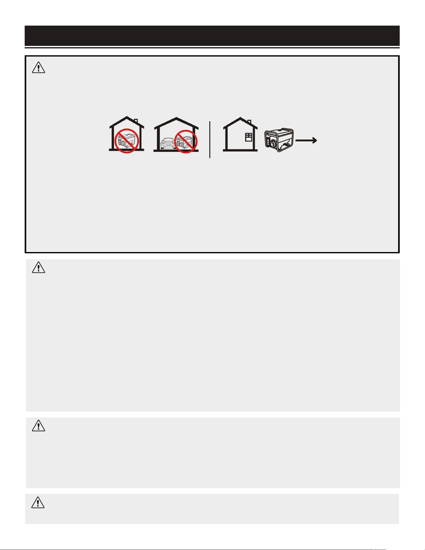
DANGER: CARBON MONOXIDE
Using a generator indoors CAN KILL YOU IN MINUTES. Generator exhaust contains carbon monox-
ide (CO). This is a poison gas you cannot see or smell. If you can smell the generator exhaust, you are
breathing CO. But even if you cannot smell the exhaust, you could be breathing CO.
NEVER use a generator inside homes, garages, crawl spaces, or other partially enclosed areas. Deadly
levels of carbon monoxide can build up in these areas. Using a fan or opening windows and doors does
NOT supply enough fresh air. ONLY use a generator OUTSIDE and far away from windows, doors, and
vents. These openings can pull in generator exhaust.
Even if you use a generator correctly, CO may leak into the home. ALWAYS use a battery-powered or
battery-backup CO alarm in the home. If you start to feel sick, dizzy, or weak after the generator has
been running, move to fresh air RIGHT AWAY. See a doctor. You may have carbon monoxide poisoning.
5

GENERATOR SAFETY WARNINGS
OPERATING ENVIRONMENT SAFETY
1. Using a generator indoors can kill you in minutes. Only use a generator outside and far away from win-
dows, doors and vents.
2. Do not operate near open flame or flammable materials. This generator may emit highly flammable and
explosive gasoline vapors, which can cause severe burns or even death if ignited. A nearby open flame can
lead to explosion even if it isn’t directly in contact with gasoline.
3. Do not smoke near the generator.
4. Do not use the generator in rainy or wet conditions; doing so significantly increases the risk of electrical
shock.
5. Always operate the generator on a dry, firm, level surface.
6. Do not allow children or non-qualified persons to operate the generator.
GENERATOR PREPARATION SAFETY
1. Always ground the generator before using it to maximize safety (see the “GROUNDING THE GENERATOR”
portion of the “GENERATOR PREPARATION” section on page 11).
2. Do not overfill fuel tank, as gasoline may expand during operation. Do not fill to the very top of the tank.
Leave room for gasoline expansion. Always check for spilled fuel before operating.
3. If any part of the generator or electrical device is broken, damaged, or defective, make sure it is repaired
or replaced before operation. Service should only be performed by a qualified technician. Do not use recep-
tacles or cords that show signs of damage, such as broken or cracked insulation.
4. Use a ground fault circuit interrupter (GFCI) in highly conductive areas such as metal decking or steel
work. Extension cords with in-line GFCIs are recommended for these operations to maximize safety.
5. NEVER connect the generator to a building’s electrical system without a qualified electrician. Such con-
nections must comply with local electrical laws and codes. Failure to comply can create a back-feed, which
may result in serious injury or death to utility workers.
WARNING: Do not let comfort or familiarity with the product replace strict adherence to product
safety rules. Failure to follow the safety instructions may result in serious personal injury.
NOTE: For power outages, permanently installed stationary generators are better suited for providing
backup power to the home. Even a properly connected portable generator can become overloaded. This
may result in overheating or stressing of the components, possibly leading to a generator failure.
6

GENERATOR SAFETY WARNINGS
GENERATOR OPERATION SAFETY
1. Only use the generator for its intended purposes. Modifying or using the generator for operations for
which it was not designed may cause hazards and personal injury.
2. Do not touch bare wires or receptacles (outlets).
3. Do not exceed the wattage capacity of the generator by plugging in more electrical devices than the unit
can handle.
4. Allow generator to run for several minutes before connecting electrical devices.
5. Do not turn ON electrical devices until after they are connected to the generator.
6. Generators vibrate in normal use. During and after the use of the generator, inspect both the generator as
well as extension and power supply cords for damage resulting from vibration.
7. Do not touch HOT PARTS. This generator produces heat when running. Temperatures near exhaust can
exceed 150º F (65º C). Allow generator to cool down after use before touching engine or areas of the gen-
erator that become hot during use.
8. Turn off all connected electrical devices before stopping the generator.
9. Always turn generator off before refueling. Allow generator to cool for at least 2 minutes before removing
fuel cap. Loosen cap slowly to relieve pressure in tank.
10. Turn the engine switch to “OFF” position when the engine is not running.
11. Empty fuel tank before storing or transporting the generator. Do not store generator or gasoline near
furnaces, water heaters, or any other appliances that produce heat or have automatic ignitions. Store the
generator and fuel away from sparks, open flames, pilot lights, heat and other sources of ignition.
CAUTION: Misuse of this generator can damage it or shorten its lifespan.
7
TO MAXIMIZE THE LIFESPAN OF YOUR GENERATOR:
We recommend running your generator at least once a month for 15 to 30 minutes. Start the generator
according to the instructions and plug a small load in to make sure the outlet is producing electricity.
If you do not run it often, it will greatly shorten the lifespan and performance of the generator.
UNPACKING & ASSEMBLY
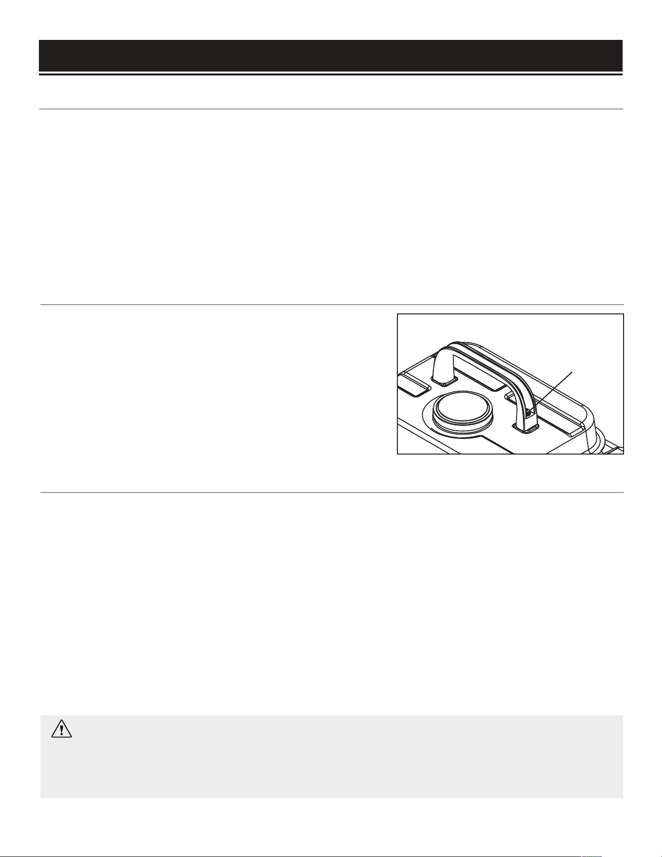
ASSEMBLY
To attach the carrying handle:
1. Remove the 2 bolts and 2 washers from the handle.
2. Position the handle over the threaded holes in the fuel tank.
3. Fasten the handle with the bolts and washers (Fig. 1 - 1).
Tighten the bolts using a Phillips-head screwdriver (not in-
cluded).
UNPACKING
Place the packaging on a sturdy, flat surface. Carefully unpack the generator and all accessories from the
box, making sure it is completely empty before discarding the package. Your generator comes with the
items listed below. Please check to see that all of the following items are included with your generator.
• Carrying Handle with 2 Bolts and 2 Washers
• Spark Plug Wrench
• Measuring Cup
If any part is damaged or missing, please contact our customer service at (800) 232-1195, M-F 8-5 CST or
email us at techsupport@wenproducts.com.
8
Fig. 1
1
HIGH ALTITUDE OPERATION ABOVE 3000 FEET
The fuel system on this generator may be affected by operation at high altitudes. Proper operation can be
ensured by installing an altitude kit. The kit can be ordered from wenproducts.com by searching the part
number 56105-HA. Use jet nozzle #68 for altitudes between 3000 to 6000 feet; use jet nozzle #65 for alti-
tudes between 6000 to 8000 feet. At elevations above 8000 feet, the engine may experience a decrease in
performance, even with the proper altitude kit.
Operating this generator without said kit may increase the engine’s emissions and decrease both fuel
economy and performance. The kit should be installed by a qualified mechanic. Refer to the instructions
included with your altitude kit for more information about installation.
CAUTION: Be sure to UNINSTALL the high altitude kit when operating at altitudes below 3000 feet. Engines
with the high-altitude kit installed operated at lower altitudes could cause severe engine damage and affect
emissions compliance.
WARNING: To prevent serious injury from fire, follow the kit installation procedures in a well-ven-
tilated area away from ignition sources. If the engine is hot from use, shut the engine off and wait for it
to cool before proceeding. Do not smoke near the generator. Warranty will be void if adjustments are not
made for high altitude use.
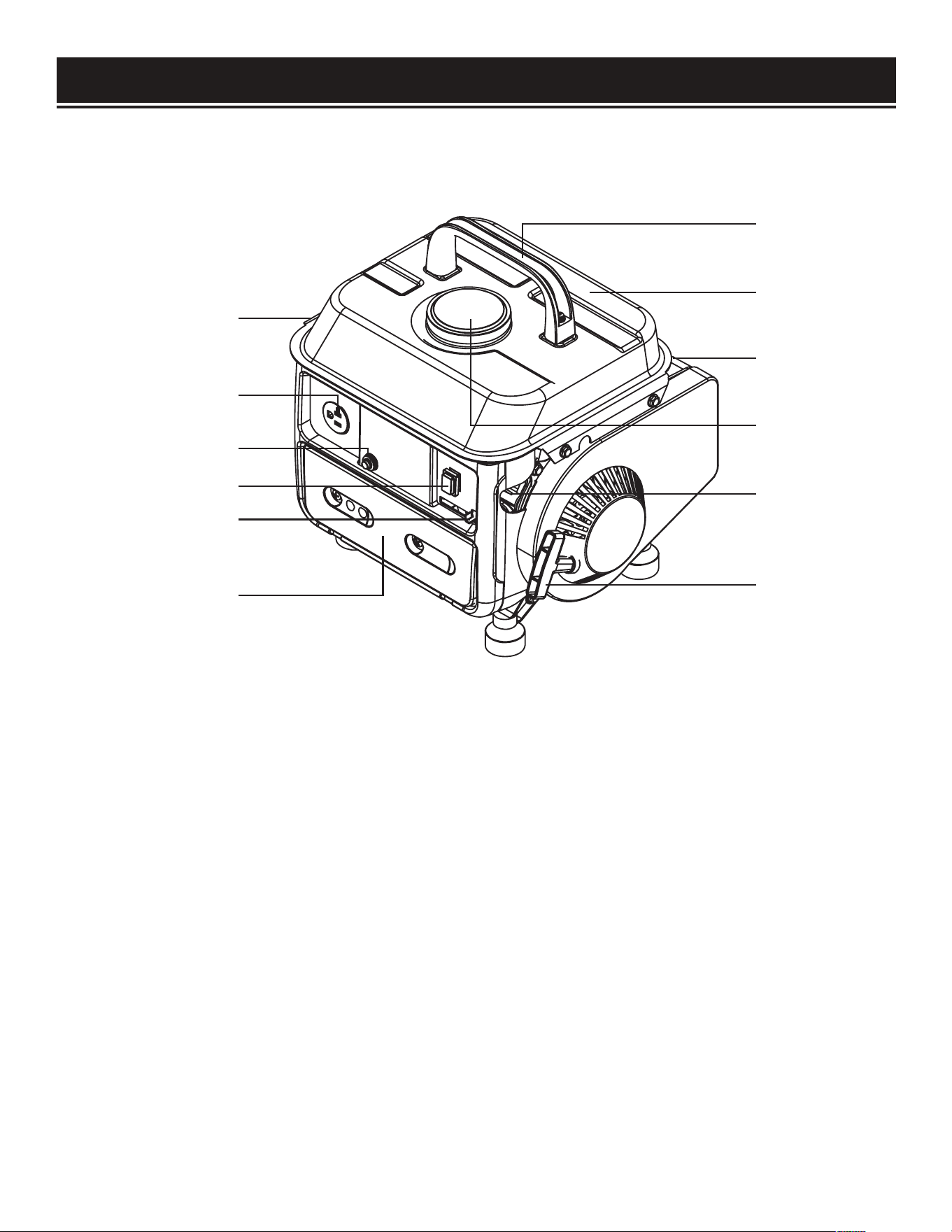
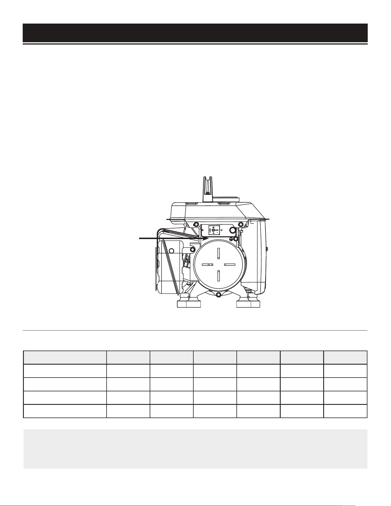
Carrying Handle
Fuel Tank
Spark Plug
(back side)
Fuel Valve
Recoil Starter
Air Cleaner Cover
Engine Switch
Choke Lever
AC 120V NEMA 5-15R
Grounding Terminal
(left side)
Circuit Reset Button
Fuel Cap
Use the illustration below to become familiar with all the components and controls of this generator.
KNOW YOUR GENERATOR
9
• Grounding Terminal - connect grounding wires
here to properly ground the generator
• 120 Volt AC Receptacle - for connecting electri-
cal devices that run on 120V, 60 Hz, single phase,
AC current
• Circuit Reset Button - Reset button that protects
the generator from outlet overload
• Engine Switch - to start/stop engine
• Choke Lever - adjusts the amount of air let into
the engine during startup
• Air Cleaner- a removable, cleanable, sponge-like
element that filters the air entering the engine
• Carrying Handle - for easy transport of the
generator (installed by user)
• Fuel Tank - 1 gallon capacity
• Spark Plug - ignites engine
• Fuel Cap - access to the fuel tank for adding
fuel
• Fuel Valve - allows fuel to enter engine from
the fuel tank
• Recoil Starter - pull-cord for starting engine

STEP 1: MIXING GASOLINE AND OIL (50:1)
GASOLINE & OIL MIXING RATIO
50:1
• For 1 gallon gasoline, use 2.5 oz oil
• For 2 gallon gasoline, use 5 oz oil
• For 5 gallon gasoline, use 13 oz oil
To mix gasoline and oil:
1. Make sure the fuel container is outside and in a well venti-
lated area.
2. Fill the clean, approved gasoline-storage container with
1/4 of the desired gasoline amount. For example, if mixing 1
gallon of gas, add 1/4-gallon into the container. This allows
sufficient space inside the container for gasoline to mix with
oil. The remaining 3/4-gallon will be added later.
GENERATOR PREPARATION
WARNING: Never store generator with fuel in the fuel tank inside a building with potential sources
of ignition such as hot water tanks, space heaters, clothes dryers, electric motors, etc.
CAUTION: DO NOT mix gasoline and oil directly in the fuel tank; use a separate, approved gasoline-
storage and dispensing container.
10
The following section describes the necessary steps to prepare the generator for use. If you are unsure
about how to perform any of the steps please call (800) 232-1195 M-F 8-5 CST for customer service. Fail-
ure to perform these steps properly can damage the generator or shorten its life.
Oil Specifications:
Use one of the following classifications of high-
quality, 2-cycle engine oil:
• NMMA
• TC-W2
• TC-W3
• JASO FB
• FASO FC
3. Measure and add the required amount of oil to the gasoline according to the mixing ratio of 50:1 (e.g. if
mixing 1 gallon of gasoline, add 2.5 oz oil).
4. Tighten the cap on the fuel container.
5. Shake the container vigorously to mix the gasoline and oil.
6. Slowly unscrew the fuel cap, as pressure may have built up inside. Slowly removing the cap allows any
pressure to dissipate. Add the remaining 3/4 portion of fuel. Wipe away any spilled fuel or oil. Tighten the
cap to avoid getting dirt or water into the mixed fuel.
Gasoline Specifications:
• Use UNLEADED gasoline with a maximum of
10% ethanol (E10 gasoline for general use).
• Fuel must be fresh (within 30 days from
purchase), and clean. NEVER use gasoline
stored for long periods.
STEP 2: FILLING THE FUEL TANK
WARNING: Keep generator away from open flame. This generator may emit highly flammable and
explosive gasoline vapors, which can cause severe burns or even death if ignited. A nearby open flame
can lead to explosion even if not directly in contact with gasoline.
• Do not operate near open flame.
• Do not smoke near the generator.
• Always operate on a firm, level surface.
• Always turn generator off before refueling. Allow generator to cool for at least 2 minutes before re-
moving fuel cap. Loosen cap slowly to relieve pressure in tank.
• Do not overfill fuel tank. Fuel may expand during operation. Do not fill to the top of the tank. Allow for
expansion.
• Always check for spilled fuel before operating. Clean up any spilled fuel before starting.
• Empty fuel tank before storing or transporting the generator to prevent spilling.
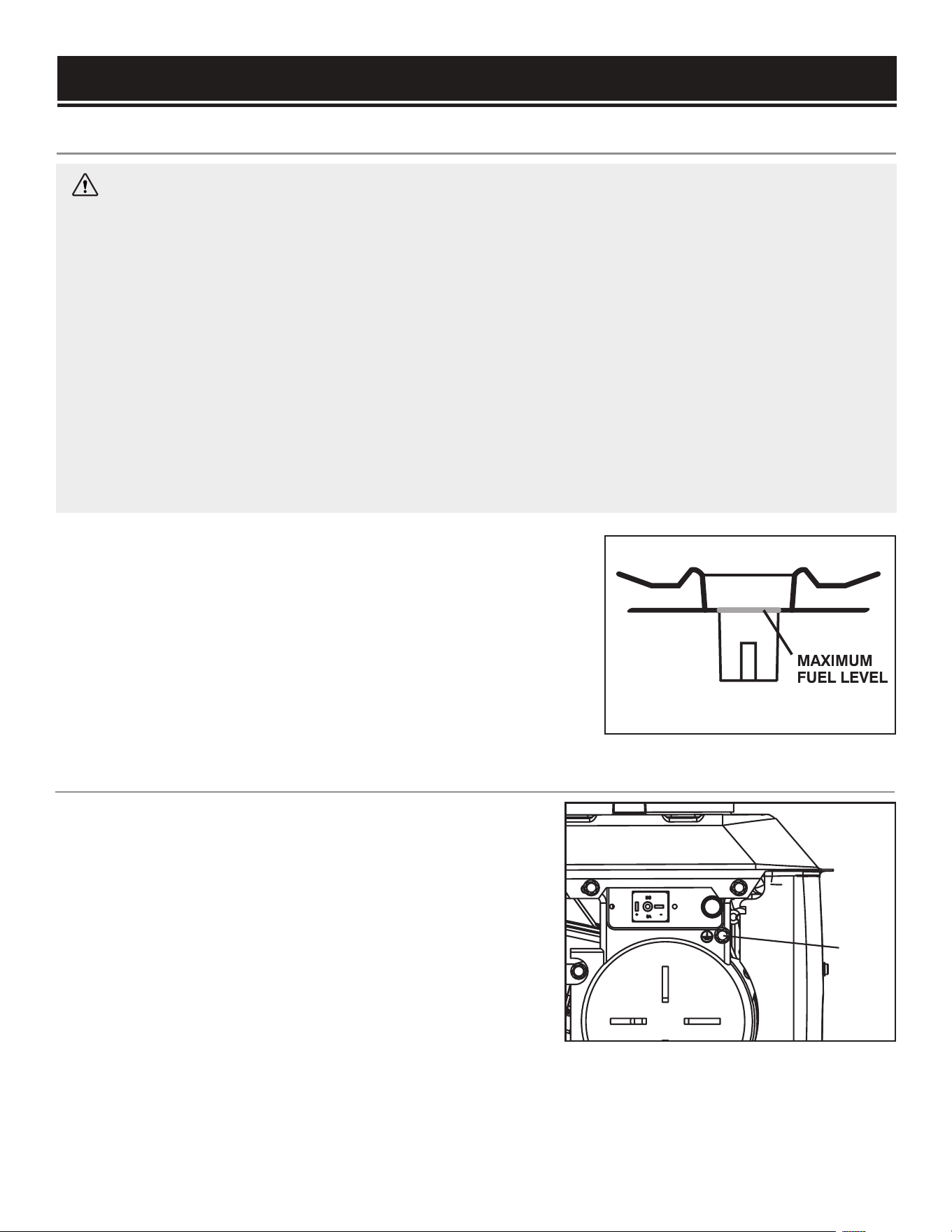
1. Clean the area around the fuel fill cap and remove the fuel fill
cap.
2. Using the gasoline/oil mixture mixed in the previous step, slowly
add the fuel into the tank. The fuel tank capacity is 1 gallon.
DO NOT overfill the fuel tank - check the maximum fuel level shown
in Fig. 2. Leave space for fuel expansion.
3. Replace the fuel fill cap and wipe up any spilled fuel.
GENERATOR PREPARATION
After completing the above preparation, the generator is ready to be started.
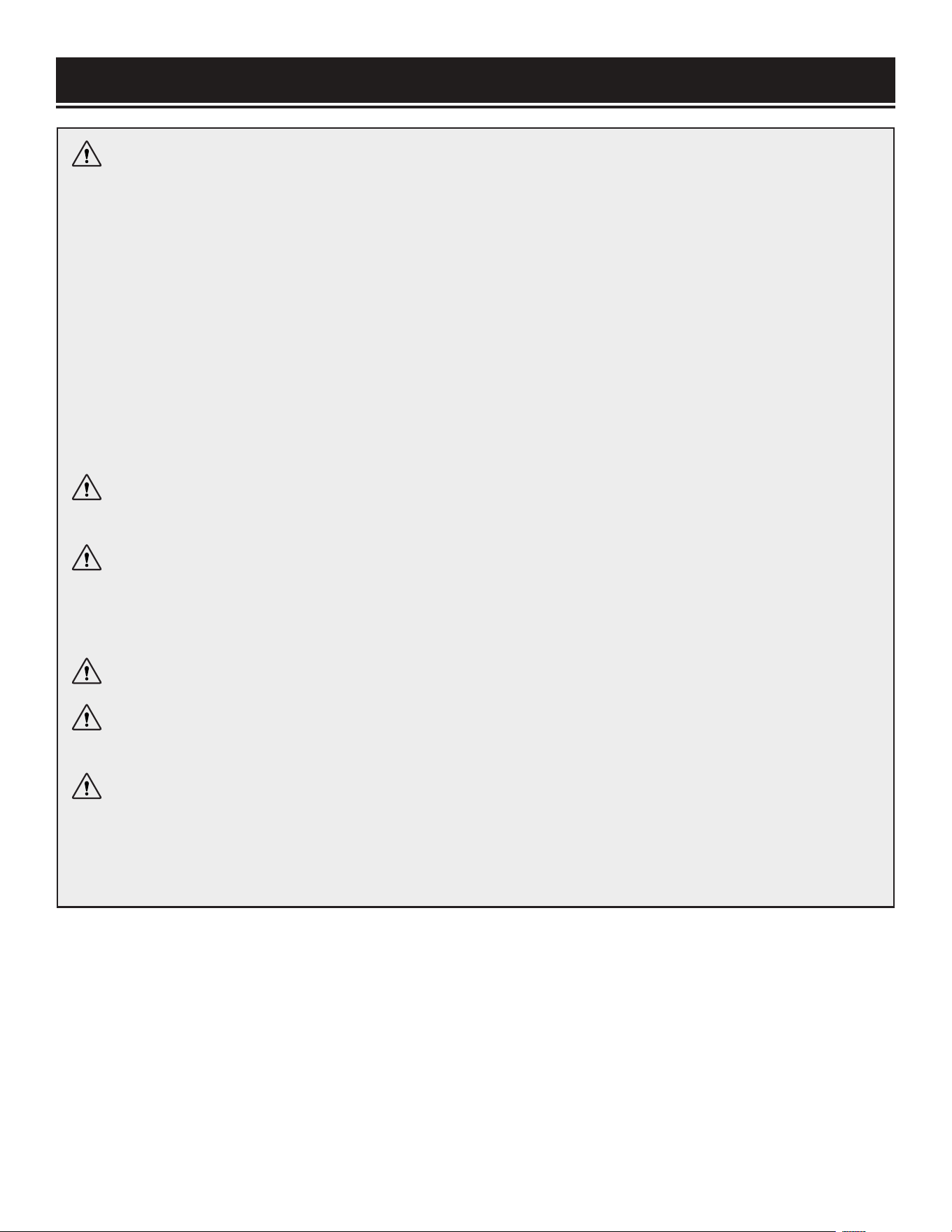
STEP 3 - GROUNDING THE GENERATOR
To reduce the risk of electric shock and to maximize safety,
the generator should be properly grounded. Ground the
generator by tightening the grounding nut on the left of the
generator (Fig. 3) against a grounding wire. A generally
acceptable grounding wire is a No. 12 AWG (American Wire
Gauge) stranded copper wire.
This grounding wire should be connected at the other end
to a copper, brass, or steel-grounding rod that is driven into
the earth. Wire and grounding rods are not included with the
generator.
Fig. 2
Fig. 3
NOTE: Grounding codes can vary by location. Contact a local electrician to check the area codes.
1
11
STARTING THE GENERATOR
To maximize safety, ALWAYS ground the generator before using it (see the “GROUNDING THE GENERATOR”
portion of the “GENERATOR PREPARATION” section).
Use a ground fault circuit interrupter (GFCI) in highly conductive areas such as metal decking or steel work.
GFCIs are available in-line with some extension cords.
CAUTION: Disconnect all electrical loads from the generator before attempting to start.
DANGER: CARBON MONOXIDE
Using a generator indoors CAN KILL YOU IN MINUTES. Generator exhaust contains carbon monox-
ide (CO). This is a poison gas you cannot see or smell. If you can smell the generator exhaust, you are
breathing CO. But even if you cannot smell the exhaust, you could be breathing CO.
NEVER use a generator inside homes, garages, crawl spaces, or other partially enclosed areas. Deadly
levels of carbon monoxide can build up in these areas. Using a fan or opening windows and doors does
NOT supply enough fresh air. ONLY use a generator OUTSIDE and far away from windows, doors, and
vents. These openings can pull in generator exhaust.
Even if you use a generator correctly, CO may leak into the home. ALWAYS use a battery-powered or
battery-backup CO alarm in the home. If you start to feel sick, dizzy, or weak after the generator has
been running, move to fresh air RIGHT AWAY. See a doctor. You may have carbon monoxide poisoning.
WARNING: The exhaust from this product contains chemicals known to the State of California to
cause cancer, birth defects, or other reproductive harm.
WARNING: DO NOT operate generator near open flame or flammable materials This generator
may emit highly flammable and explosive gasoline vapors, which can cause severe burns or even death
if ignited. A nearby open flame can lead to explosion even if it isn’t directly in contact with gasoline. Do
not smoke near the generator.
WARNING: This generator produces powerful voltage, which can result in electrocution.
WARNING: Do not use in rainy or wet conditions. Do not touch bare wires or receptacles (outlets).
Do not allow children or non-qualified persons to operate.
WARNING: Generator should only be connected to electrical devices, either directly or with an
extension cord. NEVER connect to a building electrical system without a qualified electrician and con-
nected to a transfer switch as a separately derived system. Such connections must comply with local
electrical laws and codes. Failure to comply can create a back-feed, which may result in serious injury
or death to utility workers.
12
STARTING YOUR GENERATOR
1. Place the generator outside on a dry, level surface. Allow at
least two feet of clearance on all sides of the generator.
1. No electrical devices should be connected to the generator
during startup. This can make it difficult for the engine to start.
2. Check that the generator is properly grounded (see
“GROUNDING THE GENERATOR”).
3. Make sure there is sufficient level of fuel in the fuel tank.
Add fuel if necessary (refer to “FILLING THE FUEL TANK”).
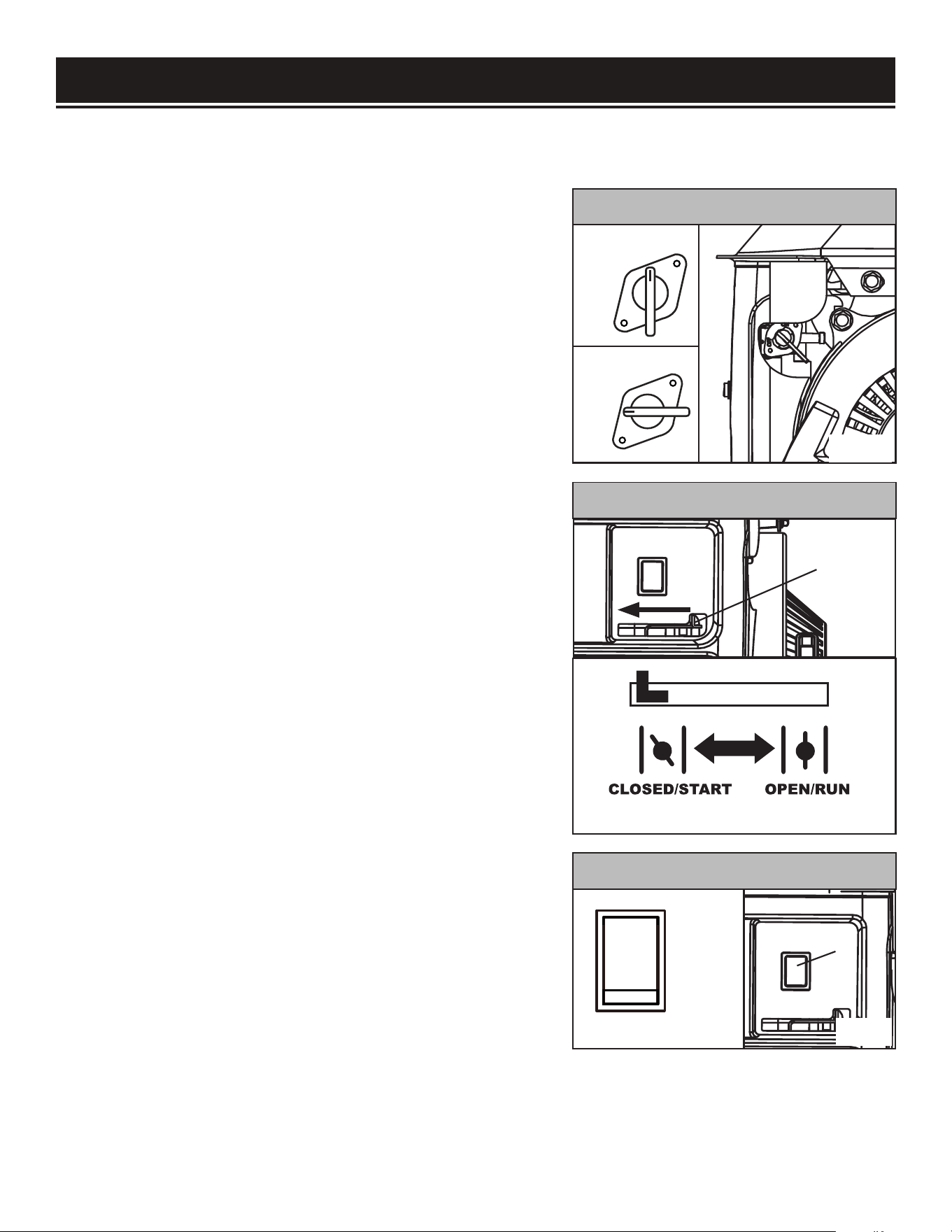
4. Turn the fuel valve to the ON position (Fig. 4, vertical posi-
tion).
5. Move the choke lever to the CLOSED position (Fig. 5 - move
lever to far left position).
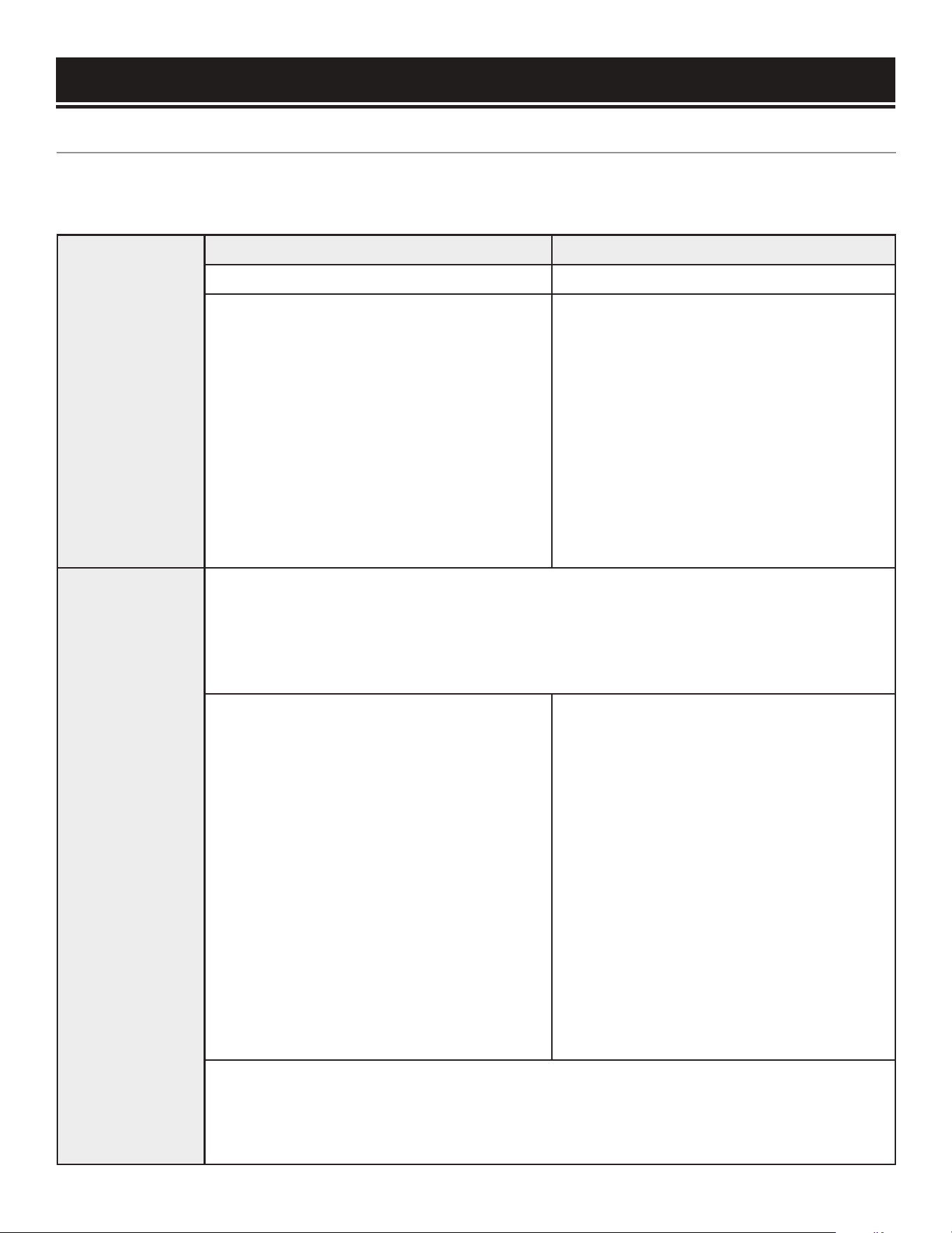
6. Set the engine switch to the ON position (Fig. 6 - until the
upper part of the rocker switch is firmly depressed).
7. Place one hand on the generator to hold it in place, and hold
the recoil starter with the other hand. Pull on the recoil starter
handle slowly until a slight resistance is felt. Then pull quickly
to start the engine. Return cord gently into the machine. Never
allow the cord to snap back.
NOTE: DO NOT place your foot on the generator and yank on
the recoil starter. That may cause excessive wear on the recoil
starter.
8. If engine fails to start, repeat step 7.
NOTE: After repeated failed attempts to start the engine, please
consult the troubleshooting guide before attempting again. If
problems persist please call (800) 232-1195 M-F 8-5 CST.
Before starting the generator, make sure you have read and performed the steps in the “Generator Prepara-
tion” section of this manual. If you are unsure about how to perform any of the steps in this manual please
call (800) 232-1195 M-F 8-5 CST for customer service.
ON
OFF
ON
OFF
9. Once the engine has started, slowly return the choke lever all
the way to the OPEN position (move lever to far right position).
13
Fig. 4
Fig. 5
Fig. 6
1
1
ON
OFF
I
O
ENGINE SWITCH
CHOKE LEVER
FUEL VALVE
10. Allow the generator to run for several minutes before attempting to connect any electrical devices. This
allows the generator to stabilize its speed and temperature.
USING THE GENERATOR
CALCULATING THE WATTAGE OF YOUR DEVICE(S)
Connect electrical devices running on AC current according to their wattage requirements. Calculate the
running wattage and starting wattage of the device(s) you wish to connect, and MAKE SURE that they are
within the capacity of your generator.
Generator
Wattage
Capacity
Generator Running (Rated) Watts Generator Starting (Surge) Watts
900W 1000W
What this means:
The generator can produce a maximum
of 900W on a continuous basis to supply
the running wattage requirement of your
electronic device(s).
What this means:
Some devices such as box fans require
short bursts of extra power in addition to
the rated wattage listed by the device to
start their motors.
The generator can produce a maximum
wattage of 1000W for a short period of
time (seconds) to cover the extra start-
ing power requirement of your electronic
devices.
Electronic
Device Wattage
Calculation
Find the wattage information of each device you plan to connect. The information
should be listed on the device or in its instruction manual, or you may refer to Fig. 7.
The wattage can be calculated using this equation:
Watts = Volts x Amperes
To calculate the total running watts of
your devices:
+ Add up the running wattages of all the
device(s) you plan to connect
= The total running wattage
This wattage should NOT exceed the gen-
erator’s running wattage of 900W.
It is recommended to maintain a load at or
below 810W (90% of the generator’s rated
output) to ensure steady voltage output
and to prolong the generator’s lifespan.
To calculate the total starting watts of
your devices:
+ Add up the total running wattage of all
the device(s) you plan to connect
+ Add the single highest ADDITIONAL
starting wattage out of the device(s) you
plan to connect
= The total surge (starting) wattage
This wattage should NOT exceed the gen-
erator’s starting wattage of 1000W.
If any of either of the total calculated running watts or starting watts is higher than the
capacity of your generator, adjust the load until both wattage requirements are met.
Otherwise you will overload the generator, and cause damage to the machine.
14
USING THE GENERATOR
Tool or Appliance Rated (Running) Watts Additional Starting Watts
Computer 800 0
Television 500 0
Garage door opener 480 0
Stereo 400 0
Box fan 300 600
Clock radio 300 0
Security system 180 0
DVD player / VCR 100 0
Common light bulb 75 0
Inflator 50 150
The chart below serves as a reference
for the estimated wattage requirements of common electrical de-
vices.
However, do not solely rely on this chart - all electronics and appliances are built differently. Always
check the wattage listed on the electrical device before consulting this chart.
Fig. 7 -
Estimated wattage requirements of common electrical devices
After the wattage information has been determined, refer to the following pages for information on
your generator’s control panel, and connecting your electrical devices to the generator.
NOTE: For power outages, permanently installed, stationary generators are better suited for providing
backup power to the home. Even a properly connected portable generator can become overloaded.
This may result in overheating or stressing the machine’s components, possibly leading to a generator
failure.
15
CONNECTING THE DEVICES
CAUTION: Become familiar with the markings on the panel before connecting electrical devices. The
120V AC receptacle is for connecting electrical devices that run on 120V, 60 Hz, single phase, AC cur-
rent. DO NOT connect 50Hz or 3-phase loads to the generator.
CAUTION: Avoid overloading the generator. Overloading your generator can damage the capacitor
the rotor in your generator and the electrical device(s) plugged into the generator.
Follow the steps below to properly connect your device(s) to the generator:
1. Before connecting electrical devices, allow the generator to run for a few minutes to stabilize the speed
and voltage output.
2. Select the device with the highest wattage, and make sure it is turned off. Plug the device into the gen-
erator and then turn the device on. Allow the engine to stabilize.
3. Repeat step 2 to plug in each additional device. DO NOT attempt to plug in or start multiple devices at the
same time.
USING THE GENERATOR
Device Requirements Max. Cord Length (ft) by Wire Gauge
Amps Watts (120V) #8 wire #10 wire #12 wire #14 wire #16 wire
2.5 300 NR NR NR 375 250
5 600 NR NR 300 200 125
7.5 900 NR 350 200 125 100
10 1200 NR 250 150 100 50
SOME NOTES ABOUT POWER CORDS
Long or thin extension cords can drain the power provided to your electrical devices. Refer to the following
chart in determining the necessary gauge extension cord for each of your devices. Round up to the higher
amperage in the chart to maximize safety.
*NR = Not Recommended
Fig. 8 - Power Cord Requirement Guide
IN CASE OF OVERLOAD
If your becomes overloaded from too much drawn wattage, the circuit breaker will shut off power to pro-
tect the generator. If an overload occurs, disconnect all electrical devices from the generator and wait five
minutes, then press the circuit breaker to reset. Check the total wattage of the devices and reduce the load
if it exceeds the capacity of the generator.
NOTE: The circuit reset button is thermally activated. The breaker has to cool down before it can be reset.
If the reset button does not reset, wait several minutes and try again. If problem persists, call our customer
service 1-800-232-1195 for further instructions.
16
STOPPING THE GENERATOR
WARNING: Allow the generator to cool down before touching areas that become hot during use.
To shut off the generator:
1. Turn off all electrical devices prior to unplugging them from the generator. Unplugging running devices
can cause damage to the generator.
2. Push the engine switch to the OFF position.
3. Turn the fuel valve to the OFF (horizontal) position.
CAUTION: Unplugging running devices can cause damage to the generator. Never stop the engine
with electrical devices connected and running.
CAUTION: Allowing gasoline to sit in the fuel tank for long periods of time can make it difficult to start
the generator in the future. Never store the generator for extended periods of time (over 2 months) with
fuel in the fuel tank. Refer to “STORING THE GENERATOR” on page 22.
17
Recommended
Maintenance Schedule
Each 8
hours or
daily
Every 25
hours
Every 3
months
or 50
hours
Every 6
months or
100 hours
Every
year
As
necessary
Air Filter
Check x* x
Clean x*
Spark Plug
Check/clean/
regap
x
Change x x
Fuel Tank
Check level x x
Drain x x
Carburetor
Drain x x
* Clean/change more often under dusty conditions or operating under heavy load.
MAINTENANCE
WARNING: Never perform maintenance operations while the generator is running. Before main-
taining or servicing the generator, turn OFF the generator, disconnect all devices and allow the generator
to cool down.
Proper routine maintenance of the generator will help prolong the life of the machine. Please perform main-
tenance checks and operations according to the Maintenance Schedule in Fig. 14. If there are any questions
about the maintenance procedures listed in this manual, please call (800) 232-1195 M-F 8-5 CST or email
techsupport@wenproducts.com.
RECOMMENDED MAINTENANCE SCHEDULE
IMPORTANT GENERATOR MAINTENANCE TIPS:
• Drain your carburetor after each use and before storage (see page 18) to prevent it from clogging.
• Do not store the generator with fuel inside the tank for more than 2 months - the fuel will go bad.
• Run the generator for at least 15 minutes every month to maximize its lifespan.
Fig. 9 - Recommended Maintenance Schedule
NOTE: Failure to properly maintain the generator can result in void the warranty.
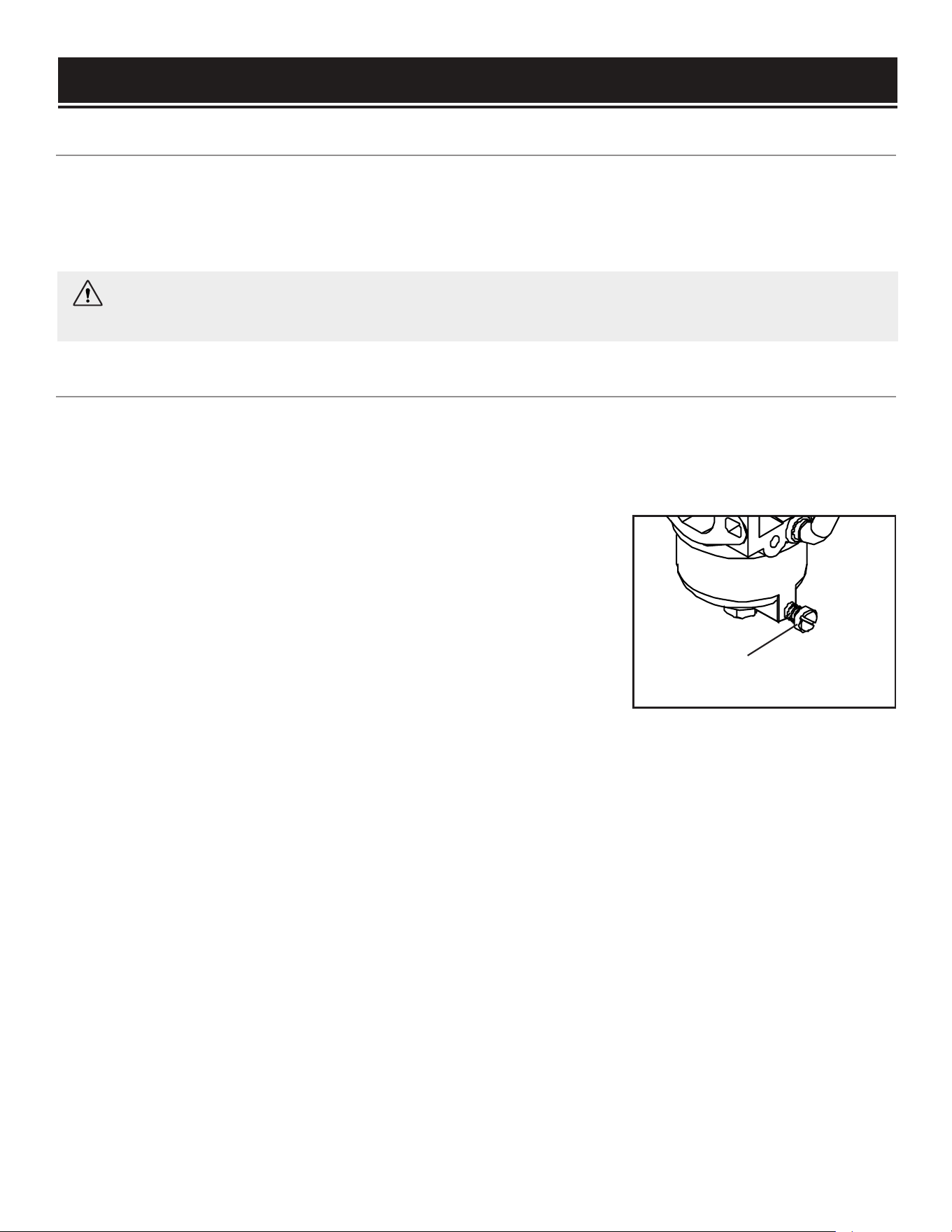
Carburetor
Drain Screw
MAINTENANCE
WARNING: Never clean the generator when it is running! Never clean with a bucket of water or a
hose. Water can get inside the working parts of the generator and cause corrosion or a short circuit.
Keep the generator clean to prevent improper operation or machine damage from dirt and debris. Inspect all
ventilation openings on the generator. These openings must be kept clean and unobstructed. If the genera-
tor becomes dirty, use a damp cloth to wipe exterior surfaces. Use a soft bristle brush to loosen dirt and oil
and use a vacuum to pick up loose dirt. Use low pressure air (not to exceed 25 PSI) to blow away dirt.
CLEANING THE GENERATOR
Recommended to drain after every use, and before storage.
Draining the carburetor is recommended to prevent the fuel from clogging up the carburetor. A clogged car-
buretor can prevent the generator from starting. Remove the front panel of the generator. The choke lever is
located on top of the carburetor.
DRAINING THE CARBURETOR
1. Open up the carburetor drain screw with a Phillips screwdriver (not
included) and drain out any gasoline that has built up inside the car-
buretor into an approved gasoline-storage container.
2. Once the fuel has drained, tighten the drain screw with the screw-
driver.
NOTE: Make sure to drain your carburetor before storing the generator
for long periods of time.
Fig. 10
18
19
WARNING: Running the engine with a dirty, damaged or missing air filter element can result in
danger to the operator and cause the engine to wear out prematurely.
Check every 50 hours of operation (refer to Fig. 9 - Recommended Maintenance Schedule).
Routine maintenance of the air filter helps maintain proper airflow to the carburetor. The air filter should be
free of excessive dirt.
AIR FILTER MAINTENANCE
To inspect and clean the air filter:
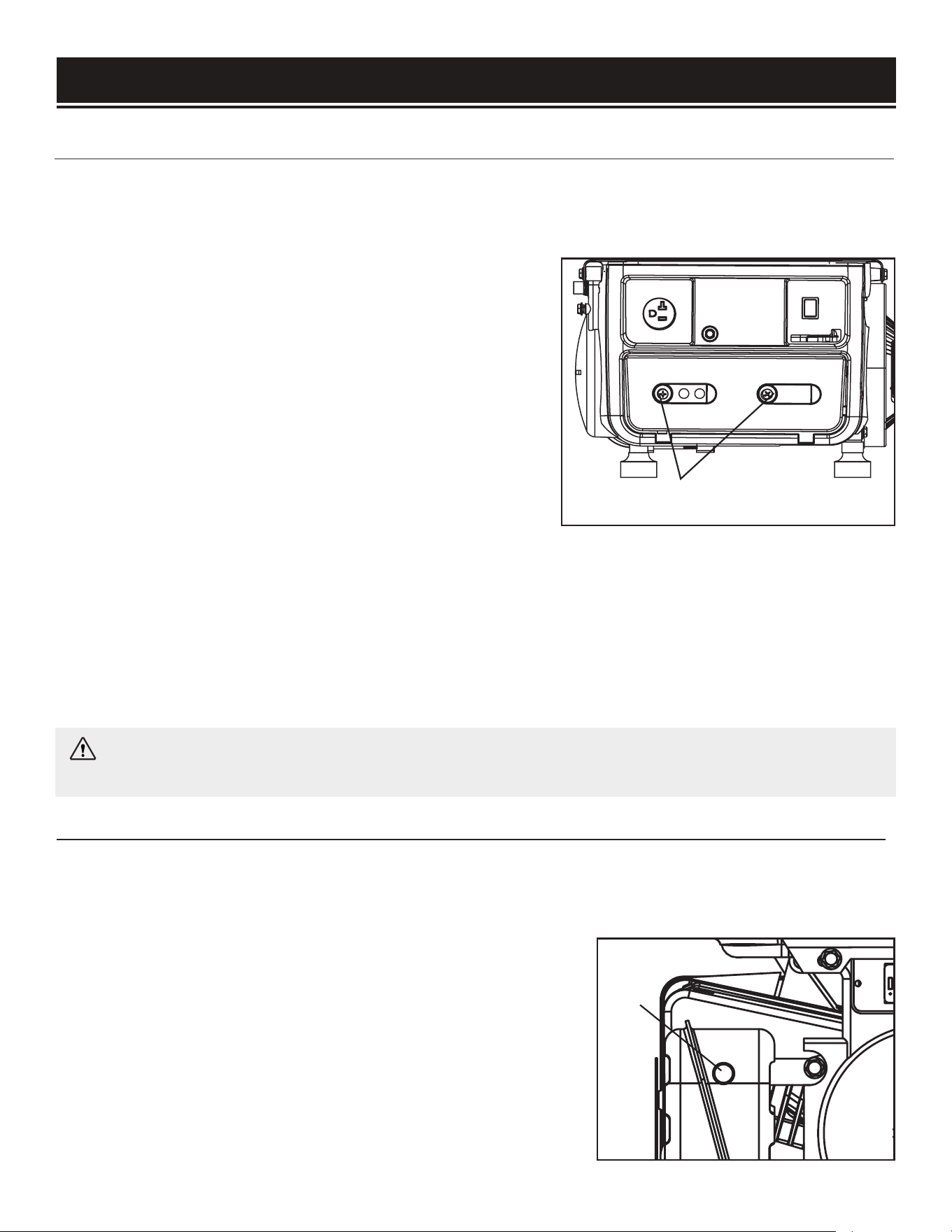
1. Undo the two screws (Fig. 11 - 1) holding the air cleaner
cover in place using a Phillips head screwdriver (not included).
2. Wear gloves; air filter is oily. Remove the air filter element.
Wipe any dirt from inside of the air filter casing.
3. Wash the element in warm soapy water. Squeeze it thor-
oughly dry in a clean cloth.
4. If the air filter element has been damaged, replace with a
new one. Replacement air filters can be ordered from wen-
MAINTENANCE
products.com by searching the Part No. 56105-079.
5. Saturate the element in clean engine oil and squeeze off excess oil in a clean absorbent cloth. Drip the
sponge-like element in clean engine oil (meeting the requirements specified on page 10), squeeze out extra
oil and reinsert into the casing. NOTE: A small amount of oil in the element is necessary for the engine to
work properly.
6. Attach the air cleaner cover with the 2 screws.
Inspect and clean the spark arrestor every 200 hours of operation (refer to Maintenance Schedule).
The spark arrester is located outside the muffler, which gets very hot during operation. Allow the engine to
cool completely before servicing the spark arrester. To inspect and clean the spark arrester:
SPARK ARRESTOR MAINTENANCE
1. Remove the screw that secures the spark arrestor to the muffler.
2. Remove the spark arrestor screen (Fig. 12 - 1).
3. Carefully clean and remove the carbon deposits from the spark
arrestor screen with a wire brush. Replace the spark arrestor if it is
damaged.
4. Reinstall the spark arrestor in the muffler and secure it in place
with the screw.
1
Fig. 11
Fig. 12
1
Refer to Recommended Maintenance Schedule in Fig. 9 for maintaining the spark plug.
The spark plug is important for proper engine operation. Check the spark plug regularly for proper engine
operation. A good spark plug should be intact, free of deposits, and properly gapped.
SPARK PLUG MAINTENANCE
MAINTENANCE
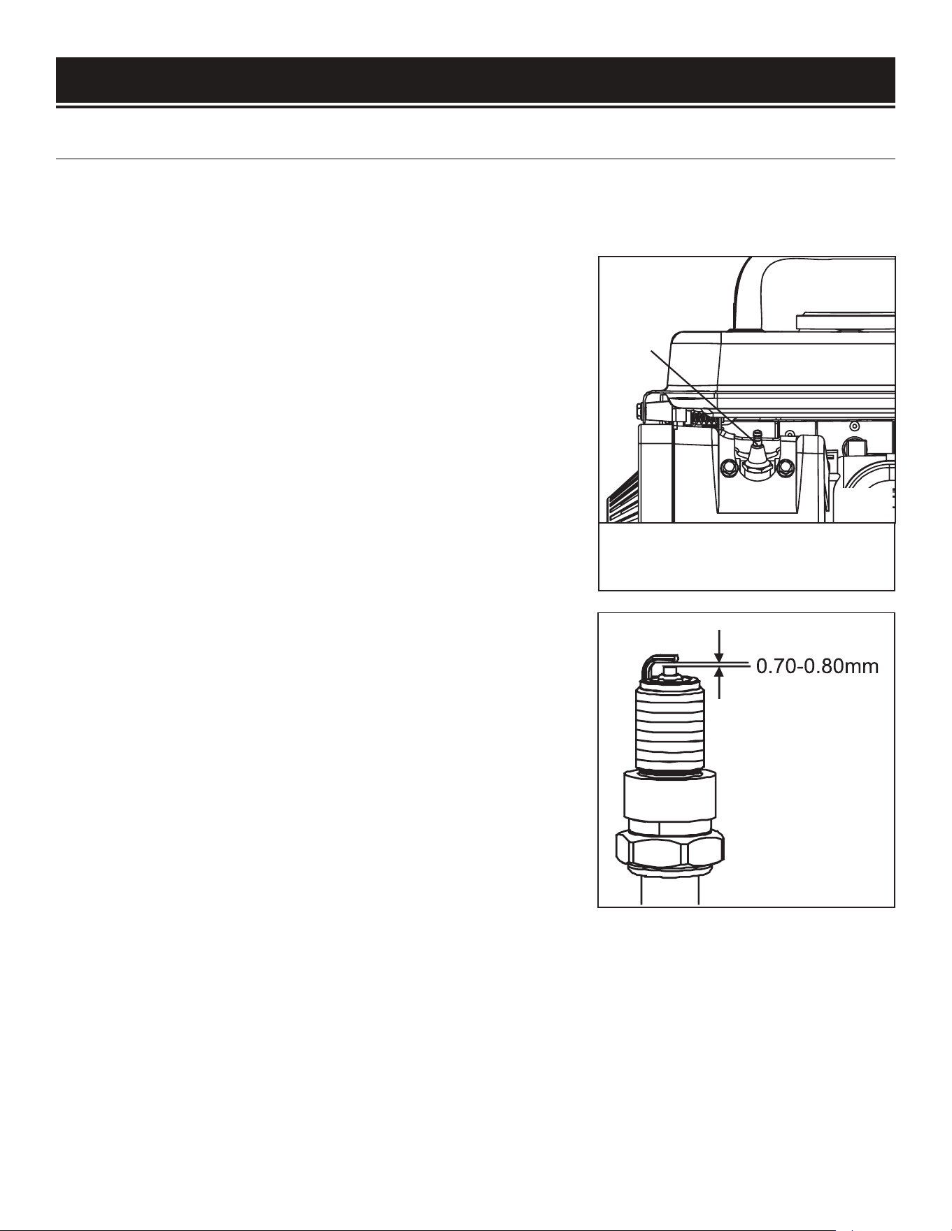
To inspect or replace the spark plug:
1. Pull on the spark plug boot to remove it. Be careful not to tear
any insulation or wire.
2. Use the included spark plug wrench to unscrew and carefully
remove the spark plug from the engine.
3. Visually inspect the spark plug. If it is cracked or chipped, or if
the electrodes are worn or burned, discard it and replace with a
new spark plug.
We recommend replacing with a NGK BP5ES spark plug (Part No.
56105-069), available for purchase at wenproducts.com.
4. If re-using the spark plug, use a wire brush to clean any dirt
from around the spark plug base, then re-gap the spark plug.
5. Measure the plug gap with a spark plug gap gauge. The gap
should be 0.7 to 0.8 mm (0.028-0.031 in.) (Fig. 14). Carefully
adjust the gap if necessary.
6. Screw the spark plug back into the spark plug hole by hand.
After the spark plug is properly seated, use the spark plug
wrench to tighten it.
Do not over-tighten the spark plug.
NOTE: The spark plug torque is 9 - 12 N.m ( 7 - 8 ft.lb). The
spark plug should be tightened 1/2 to 3/4 turn after spark plug
gasket contacts spark plug hole.
7. Reinstall the spark plug boot over the spark plug.
Recommended Spark Plug:
NGK BP5ES, Torch F5TC or Similar
1
20
Fig. 13
Fig. 14
21
Clean the fuel tank each year, or before storing the generator for extended periods of time.
To drain the fuel tank:
DRAINING THE FUEL TANK
CAUTION: Do not store fuel for more than 2 months. Fuel stored for longer than 2 months can go bad.
MAINTENANCE
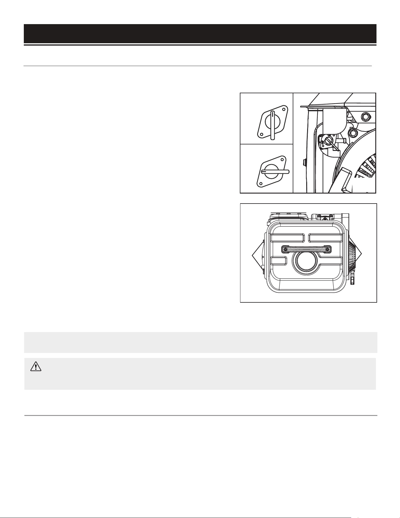
1. Turn the fuel valve to the OFF (horizontal) position.
2. Remove the four bolts holding the fuel tank onto the gen-
erator frame (Fig. 16 - 1).
3. Lift the fuel tank and rotate it so as to clear the tank from
the generator frame. The fuel valve should be visible. Place a
approved gasoline-storage container under the fuel valve to
catch fuel when the fuel line is disconnected.
4. Using a pair of pliers, slide the fuel line clamp off the fuel
valve so the line can be disconnected.
5. Collect any fuel left in the fuel line going to the carburetor.
6. Place the fuel tank over the fuel collecting container and
open the fuel valve. The fuel should drain from the tank.
7. Reconnect the fuel line and reattach the fuel tank with the
four bolts.
8. Start and run the engine until fuel runs out.
9. Store the emptied fuel in a suitable place.
1
1
Fig. 15
ON
OFF
ON
OFF
Fig. 16
WARNING: Never store generator with fuel in the fuel tank inside a building with potential sources
of ignition such as hot water tanks, space heaters, clothes dryers, electric motors, etc.
Do not dispose of used generator or parts with your household waste. This product contains electrical or
electronic components that should be recycled. Please take this product to your local recycling facility for
responsible disposal to minimize its environmental impact.
Do not dispose of used oil or fuel in the trash or down a drain. Please contact your local recycling center or
auto garage to arrange proper oil/fuel disposal.
PRODUCT DISPOSAL
To prevent fuel spillage when transporting, be sure to perform the following:
1. Tighten the fuel cap.
2. Set the engine switch to OFF.
3. Drain the fuel tank if possible (see “DRAINING THE FUEL TANK”
page 21
).
4. Keep the generator upright. Never place the generator on its side or upside down - doing so will make
it difficult to start.
TRANSPORTING THE GENERATOR
WARNING: Avoid direct sunlight inside a vehicle. If the generator is left in an enclosed vehicle for
many hours, the high temperature could cause the fuel to vaporize and result in a possible explosion.
22
TRANSPORTATION & STORAGE
Shut off the generator and allow the unit to cool to room temperature before storing it. NEVER place any
type of storage cover on the generator while it is still hot. Do not obstruct any ventilation openings.
Follow the procedures below for properly storing your generator. We highly recommend running your gen-
erator once a month for 15 to 30 minutes. Plug in a small load in to ensure there is proper power output.
STORING THE GENERATOR
For Short Periods (30 to 60 Days):
• Drain the carburetor (see page 18).
• Gasoline stored over 30 days can start to go bad and
damage fuel system components.
Add fuel stabilizer:
Follow the suggested portions and instructions of your
preferred stabilizer. Run the engine for 15 to 20 minutes,
allowing the fuel stabilizer to mix with the gasoline and
circulate through the carburetor, and then top off with
fuel. Filling the fuel tank full reduces the amount of air in
the tank and helps fight deterioration of fuel.
For Extended Periods
(Over 60 Days):
• Drain the carburetor (see page 18).
• Drain the fuel tank (see “
DRAINING THE
FUEL TANK”
on page 21). Never store with
fuel in the tank for more than two months.
WARNING: Store the generator upright in a cool and dry location, away from sources of heat, open
flames, sparks or pilot lights.
23
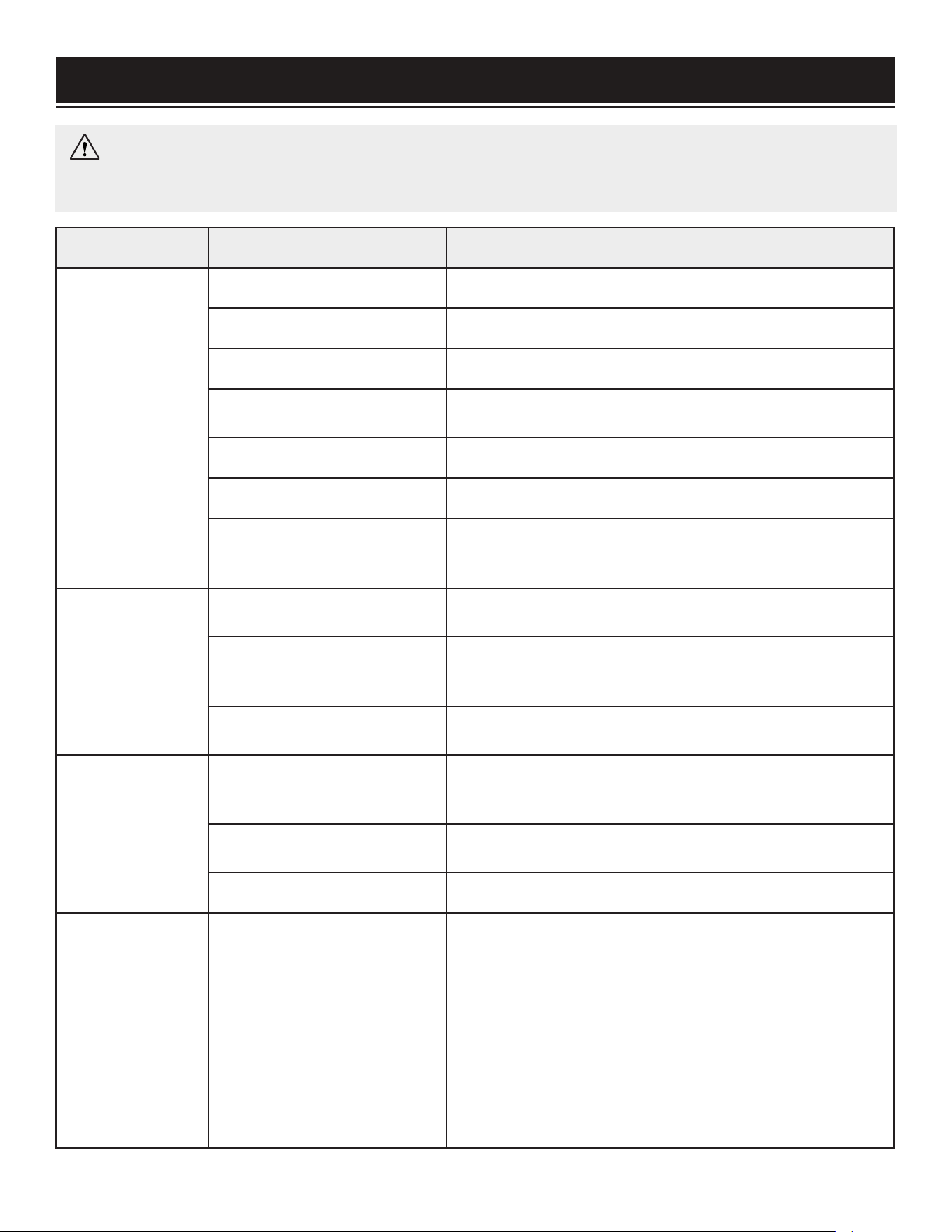
TROUBLESHOOTING GUIDE
PROBLEM POSSIBLE CAUSE SOLUTION
Engine will not
start.
Engine switch is set to OFF. Set engine switch to ON.
Fuel valve is turned to OFF. Turn fuel valve to ON.
Engine is out of fuel. Add fuel (see page 10).
Engine is filled with
contaminated or old fuel.
Drain fuel in the tank (see page 21). Fill with fresh fuel
(see page 10).
Spark plug is dirty or broken. Clean or replace the spark plug (see page 20).
Air filter element is dirty Clean or replace air filter element (see page 19).
Carburetor is air locked.
Remove the screw from the bottom of the carburetor and
remove the carburetor bowl to allow the float to reset.
Replace bowl and reinstall screw.
Engine runs but
there is no
electrical output.
Circuit reset button has been
tripped due to overload.
Wait for 2 minutes and push the circuit reset button to
reset it.
Bad connecting cords/wires.
Check the power cords and extension cords. Do not use
if any cord is damaged. Replace damaged cords imme-
diately.
Bad electrical device con-
nected to the generator.
Try connecting a different device.
Generator runs
but does not sup-
port all electrical
devices con-
nected.
Generator is overloaded.
Turn off and unplug all electrical devices. Turn off genera-
tor. Wait 5 minutes, then press the circuit breaker to reset.
Reduce load before starting the generator.
Short circuit in one of the
devices.
Try disconnecting any faulty or short-circuited electrical
loads.
Air filter is dirty. Clean or replace the air filter element (see page 19).
Engine is
“Hunting” during
Operation
(Engine RPM is
fluctuating).
1. The fuel isn’t running
through the fuel valve.
2. The air filter is clogged.
3. The muffler or spark ar-
rester is blocked
4. There is gunk in the car-
buretor preventing a con-
sistent fuel/air mixture from
forming.
Turn off the generator and wait for it to cool down. Per-
form the following steps:
1. Check if the fuel is properly and consistently going
through the fuel valve
2. Check for any blockage in the air filter. Check and
clean the air filter as necessary (see page 19).
3. Check if the spark arrester is blocked. Clean with
metal brush as necessary (see page 20).
4. Use “gunk remover” spray on the carburetor jets.
WARNING: Stop using the generator immediately if any of the following problems occur or risk se-
rious personal injury. If you have any questions, please contact our customer service at (800) 232-1195,
M-F 8-5 CST or email us at techsupport@wenproducts.com.
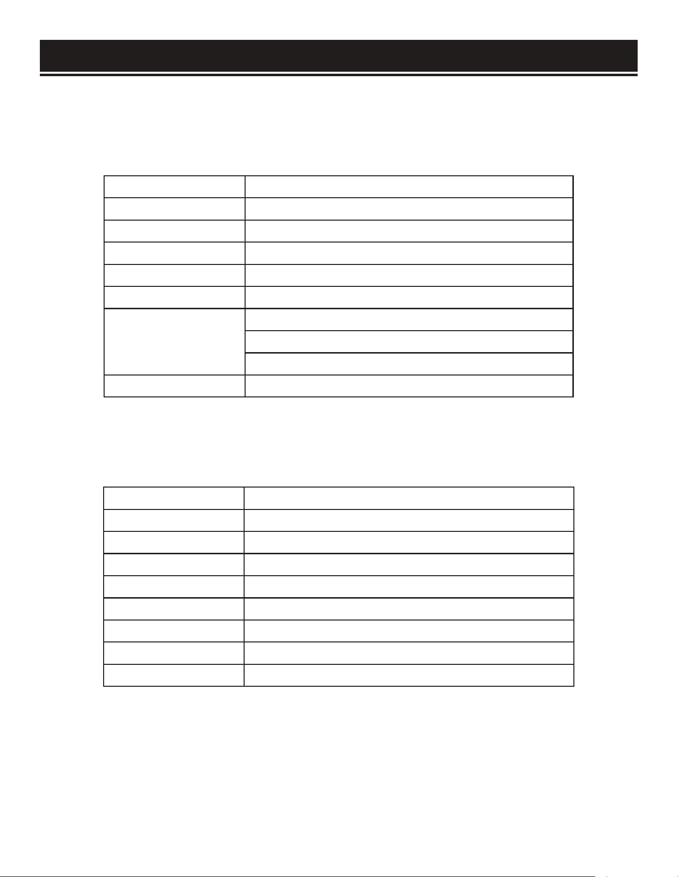
SPECIFICATIONS
Rated Wattage 900 Watts
Surge Wattage 1000 Watts
Phase Single
Rated Frequency 60Hz
Rated Voltage AC 120V
Rated Amperage 7A
Product Dimensions
Length: 15 in.
Width: 12 in.
Height:14.5 in.
Product Net Weight 39 lbs
Engine Type 2-stroke, single cylinder with forced air cooling system
Engine Displacement 63cc
Engine Ignition System Non-Contact Transistor
Fuel Tank Capacity 1 US gallon (4L)
Half-Load Run Time 5 hours
Full-Load Noise Rating 95 dB at 13 feet (4m)
Spark Plug Type NGK BP5ES, Torch F5TC
Spark Plug Gap 0.7 - 0.8 mm (0.028 - 0.031 in)
Spark Plug Torque 9 - 12 N.m ( 7 - 8 ft.lb)
GENERATOR
ENGINE
24
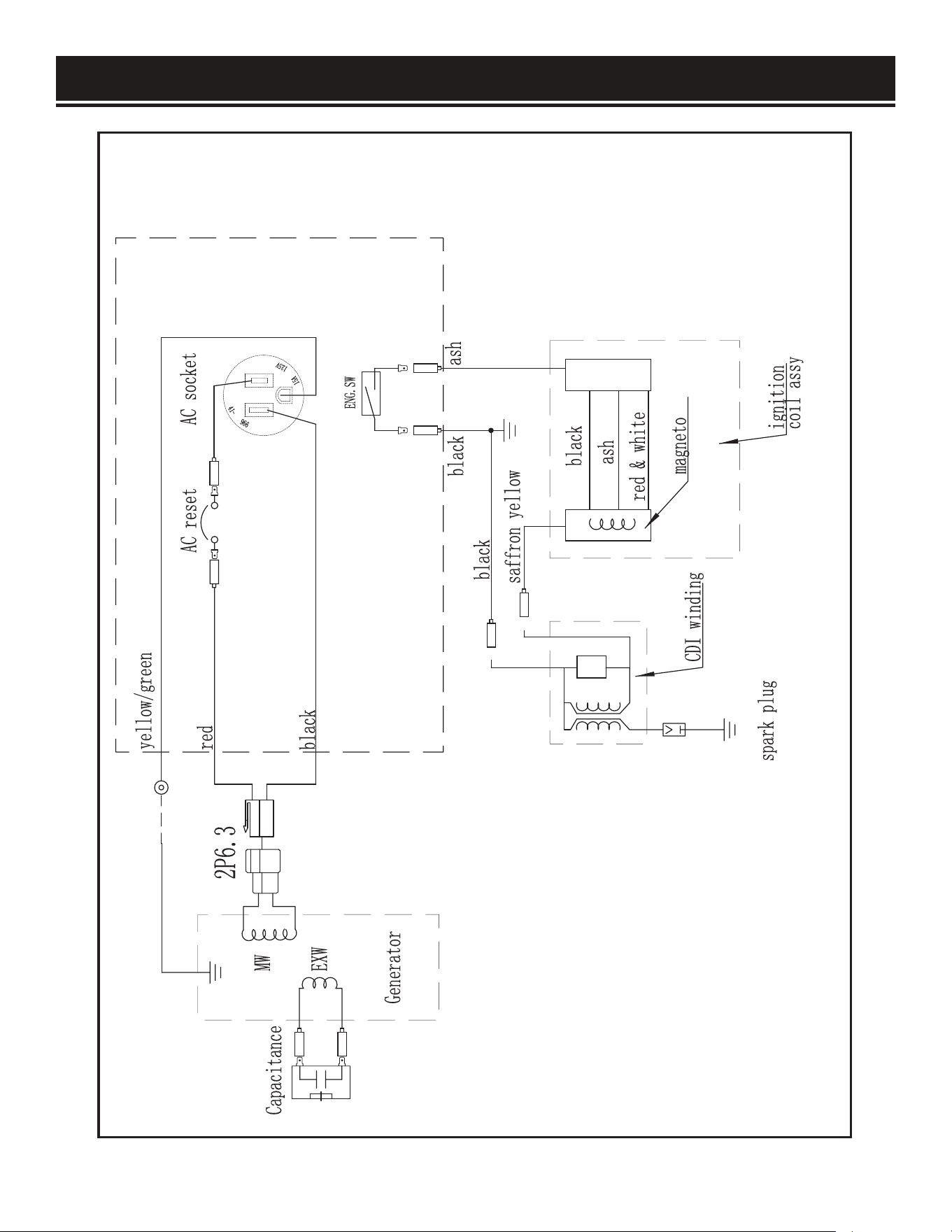
WIRING DIAGRAM
25
26
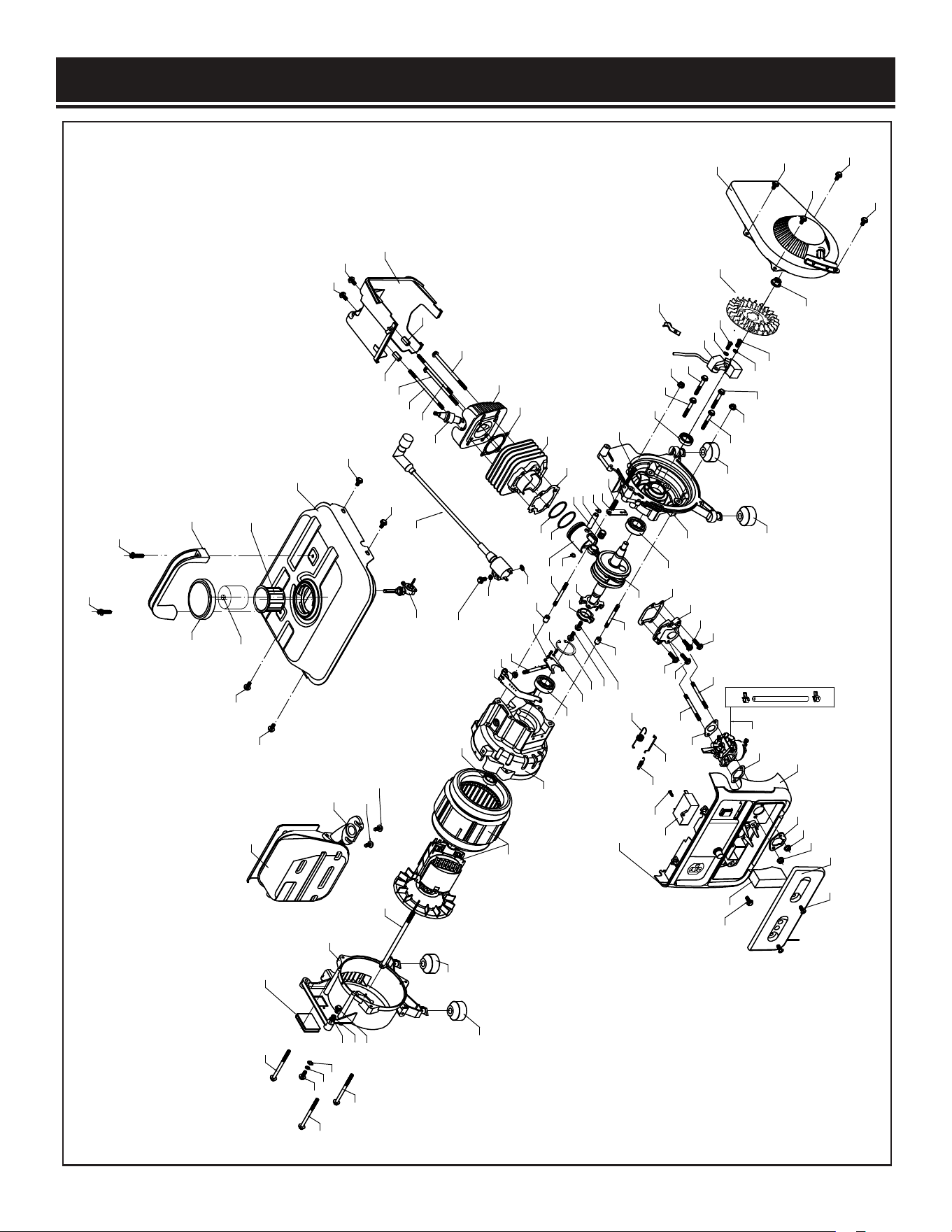
EXPLODED VIEW & PARTS LIST
56
56
57
58
60
61
63
64
63
62
62
62
64
63
65
66
36
47
37
37
37
55
54
53
52
51
50
44
46
45
45
48
49
9
44
44
44
43
42
41
40
3938
38
37
37
34
34
34
34
6
21
23
22
8
8
8
34
34
34
34
35
34
34
6
15
7
28
29
30
31
32
32
31
33
27
26
25
24
21
20
10
10
9
8
9
7
14
1
3
18
17
16
11
12
13
9
3
9
8
2
5
5
4
19
19
19
1
1
9
77
69
70
70
70
0
8
70
71
72
74
75
75
76
73
78
68
67
67
7
59

27
EXPLODED VIEW & PARTS LIST
No. Part No. Description Qty.
1 56101-001 Left Crankcase 1
2 56101-002 Right Crankcase 1
3 56101-003 Bearing 6004 2
4 56101-004 Hole Circlip Ø45 1
5 56101-005 Oil Seal 20x30x7 2
6 56101-006 Pin 10*7*14 2
7 56101-007 Stud M6x50 2
8 56101-008 Toothed Flange Nut M6 4
9 56101-009 Flange Bolt M6x45 4
10 56101-010 Stud M6x100 2
11 56101-011 Oil Seal 6*12*4 1
12 56101-012 Governor Shaft 1
13 56101-013 Governor Fork 1
14 56101-014 Cross Round Head Bolt M3x8 2
15 56101-015 Spring Washer Ø3 2
16 56101-016 Governor Arm 1
17 56101-017 Collar Bushing 1
18 56101-018 Centrifugal Switch 1
19 56101-019 Flange Bolt M6x16 4
20 56101-020 Crankshaft Assembly 1
21 56101-021 Circlip 2
22 56101-022 Piston Pin 1
23 56101-023 Roller Bearing 14x10x13 1
24 56101-024 Piston 1
25 56101-025 Second Piston Ring 1
26 56101-026 First Piston Ring 1
27 56101-027 Cylinder Gasket 1
28 56101-028 Cylinder 1
29 56101-029 Cylinder Cap Gasket 1
30 56101-030 Cylinder Head 1
31 56101-031 Flange Bolt M6x105 2
32 56101-032 Thick Nut M6x18 2
33 56101-033 Cylinder Head Cover 1
34 56101-034 Flange Bolt M6x12 10
35 56101-035 Ignition Coil Assembly 1
36 56101-036 Clamp 1
37 56101-037 Spring Washer Ø6 5
38 56101-038 Cross Round Head Bolt M6x16 2
39 56101-039 Flywheel 1
40 56101-040 Flange Nut M10x1.25 1
41 56101-041 Recoil Starter Assembly 1
No. Part No. Description Qty.
42 56101-042 Intake Valve Gasket 1
43 56101-043 Intake Valve Assembly 1
44 56101-044 Flange Bolt M6x18 4
45 56101-045 Stud M6x60 2
46 56101-046 Intake Gasket 1
47 56101-047 Carburetor 1
48 56101-048 Carburetor Gasket B 1
49 56101-049 Carburetor Gasket A 1
50 56101-050 Supporting Plate 1
51 56101-051 Compression Spring 1
52 56101-052 Cross Round Head Bolt M6x40 1
53 56101-053 Rod Link 1
54 56101-054 Tension Spring 1
55 56101-055 Governor Spring 1
56 56101-056 Control Panel Assembly 1
57 56101-057 Capacitor 1
58 56101-058
Self-Tapping Screw
ST4.2x14
1
59 56105-059 Rotor/Stator Assembly 1
60 56105-060 Flange Bolt M8*160 1
61 56105-061 Rear Cover 1
62 56101-063 Flange Bolt M6x80 3
63 56101-064
Toothed Washer Ø6
3
64 56101-065 Flange Bolt M6x10 2
65 56101-066 Muffler 1
66 56101-067 Muffler Gasket 1
67 56101-068 Flange Bolt M6x16 2
68 56105-068 Spark Plug Boot Assembly 1
69 56101-070 Spark Plug NGK BP5ES 1
70 56101-071 Rubber Foot 4
71 56105-071 Fuel Tank 1
72 56101-073 Fuel Filter 1
73 56100-044 Fuel Tank Cap 1
74 56101-075 Handle 1
75 56101-076 Cross Round Head Bolt M6x30 1
76
56100-041-1
Fuel Switch 1
77
56101-080
Fuel Measuring Cup 1
78 56101-079 Rubber Cover 1
79 56105-079 Air Filter Element 1
80 56105-080 Air Filter Cover 1
81 56105-081 Air Filter Cover Screw 2

WARRANTY STATEMENT
WEN Products is committed to building tools that are dependable for years. Our warranties are consistent with this
commitment and our dedication to quality.
LIMITED WARRANTY OF WEN PRODUCTS FOR HOME USE
GREAT LAKES TECHNOLOGIES, LLC (“Seller”) warrants to the original purchaser only, that all WEN consumer power
tools will be free from defects in material or workmanship during personal use for a period of two (2) years from date
of purchase or 500 hours of use; whichever comes first. Ninety days for all WEN products if the tool is used for pro-
fessional or commercial use. Purchaser has 30 days from the date of purchase to report missing or damaged parts.
SELLER’S SOLE OBLIGATION AND YOUR EXCLUSIVE REMEDY under this Limited Warranty and, to the extent per-
mitted by law, any warranty or condition implied by law, shall be the replacement of parts, without charge, which are
defective in material or workmanship and which have not been subjected to misuse, alteration, careless handling,
misrepair, abuse, neglect, normal wear and tear, improper maintenance, improper storage, incorrect lubricants/
fuels, or other conditions adversely affecting the Product or the component of the Product, whether by accident or
intentionally, by
persons other than Seller. To make a claim under this Limited Warranty, you must make sure to keep
a copy of your proof of purchase that clearly defines the Date of Purchase (month and year) and the Place of Pur-
chase. Place of Purchase must be a direct vendor of Great Lakes Technologies, LLC. Purchasing through third party
vendors, including but not limited to garage sales, pawn shops, resale shops, or any other secondhand merchant,
voids the warranty included with this product. Contact [email protected] or 1-800-232-1195 with the
following information to make arrangements: your shipping address, phone number, serial number, required part
numbers, and proof of purchase. Damaged or defective parts and products may need to be sent to WEN before the
replacements can be shipped out.
Upon the confirmation of a WEN representative, your product may qualify for repairs and service work. When re-
turning a product for warranty service, the shipping charges must be prepaid by the purchaser. The product must
be shipped in its original container (or an equivalent), properly packed to withstand the hazards of shipment. The
product must be fully insured with a copy of the proof of
purchase enclosed. There must also be a description of the
problem in order to help our repairs department diagnose and fix the issue. Repairs will be made and the product
will be returned and shipped back to the purchaser at no charge for addresses within the contiguous United States.
THIS LIMITED WARRANTY DOES NOT APPLY TO ITEMS THAT WEAR OUT FROM REGULAR USAGE OVER TIME,
INCLUDING FILTERS, SPARK PLUGS, VOLTAGE REGULATORS, BRUSHES, GASKETS, O-RINGS, WHEEL KITS, BAT-
TERIES, RECOIL STARTERS, HIGH PRESSURE HOSES, SPRAY GUNS, ETC. ANY IMPLIED WARRANTIES SHALL
BE LIMITED IN DURATION TO TWO (2) YEARS FROM DATE OF PURCHASE. SOME STATES IN THE U.S. AND SOME
CANADIAN PROVINCES DO NOT ALLOW LIMITATIONS ON HOW LONG AN IMPLIED WARRANTY LASTS, SO THE
ABOVE LIMITATION MAY NOT APPLY TO YOU.
IN NO EVENT SHALL SELLER BE LIABLE FOR ANY INCIDENTAL OR CONSEQUENTIAL DAMAGES (INCLUDING BUT
NOT LIMITED TO LIABILITY FOR LOSS OF PROFITS) ARISING FROM THE SALE OR USE OF THIS PRODUCT. SOME
STATES IN THE U.S. AND SOME CANADIAN PROVINCES DO NOT ALLOW THE EXCLUSION OR LIMITATION OF IN-
CIDENTAL OR CONSEQUENTIAL DAMAGES, SO THE ABOVE LIMITATION OR EXCLUSION MAY NOT APPLY TO YOU.
THIS LIMITED WARRANTY GIVES YOU SPECIFIC LEGAL RIGHTS, AND YOU MAY ALSO HAVE OTHER RIGHTS
WHICH V
ARY FROM STATE TO STATE IN THE U.S., PROVINCE TO PROVINCE IN CANADA AND FROM COUNTRY
TO COUNTRY.
THIS LIMITED WARRANTY APPLIES ONLY TO ITEMS SOLD WITHIN THE UNITED STATES OF AMERICA, CANADA
AND THE COMMONWEALTH OF PUERTO RICO. FOR WARRANTY COVERAGE WITHIN OTHER COUNTRIES, CON-
TACT THE WEN CUSTOMER SUPPORT LINE. FOR WARRANTY PARTS OR PRODUCTS REPAIRED UNDER WAR-
RANTY SHIPPING TO ADDRESSES OUTSIDE OF THE CONTIGUOUS UNITED STATES, ADDITIONAL SHIPPING
CHARGES MAY APPLY.
28 v.2019.0725