IMPORTANT INSTRUCTIONS
AND OPERATING MANUAL
ITEM NO.: Z4790
MODEL NO.: IMC9000-UL
Thank you for purchasing this product! Please read the instructions carefully
before using your portable ice maker. If you have any questions about the
product, please contact us via Amazon Message or customer service
number: 213-4467172 or 661-4358826

1
IMPORTANT SAFETY
INSTRUCTIONS
To reduce the risk of fire, explosion, electric shock, or injury when
using your ice maker, follow these important safety instructions:
1. Before using check that the voltage power corresponds to the one
shown on the unit nameplate.
2. Do not remove any safety, warning, or product information labels from
your ice maker.
3. Plug the ice maker into an exclusive grounded power outlet. No other
unit should be plugged into the same outlet. Be sure that the plug is fully
inserted into the receptacle.
4. This unit must be grounded. It is equipped with a power cord having a
grounding plug. The plug must be plugged into an outlet that is properly
installed and grounded.
5. Avoid the use of an extension cord because it may overheat and cause
a risk of fire. However, if it is necessary to use an extension cord:
(1) Use only extension cord with grounding plug.
(2) The marked rating of an extension cord must be equal to or greater
than the rating of this unit.
(3) It should be positioned such that it does not drape over the counter or
tabletop where it can be pulled on by children intentionally.
6. Do not operate any unit with a damage cord or plug or after the unit
malfunction or has been damaged in any manner. Return the unit to the
nearest authorized service facility for examination, repair or adjustment.
7. If the supply cord is damaged, it must be replaced by the manufacturer
or its service agent or a similarly qualified person in order to avoid a
hazard.
8. Do not let cord hang over edge of table or counter.
9. Do not place on or near a hot gas or electric burner, or in a heated oven.
10. Place power cord in such a way it cannot be pulled on by children or
cause a tripping hazard.
11. Place power cord in such a way that it is not in contact with hot surfac-
es.
12. The use of attachment not recommended or sold by manufacturer
may cause fire, electric shock or injury.
13. Do not touch the evaporator when using the ice maker or making ice to
avoid suffering from frostbite.
14. Do not immerse any part of the product in water.
15. To disconnect, turn any control to “OFF”, then remove plug from wall
outlet.
16. Do not plug or unplug product with wet hands.
17. Unplug the product before cleaning,maintaining and when not in use.

2
18. Do not use with water that is microbiologically unsafe or of unknown
quality.
19. Do not clean your ice maker with any flammable fluids. The fumes may
create a fire hazard or explosion.
20. Do not overturn the ice maker. If the ice maker is overturned acciden-
tally, make it stand steadily for 2 hours before power it on again.
21. If the ice maker is brought in from outside in wintertime, do not use for
a few hours, allowing the unit to warm up to the room temperature before
operating.
22. Never put flammable, explosive and corrosive articles into the ice
maker.
23. Never use the ice maker when there is flammable gas leakage.
24. Never store or use gas and other flammable articles near the ice
maker to avoid any fire.
25. Unplug the ice maker before moving it to avoid damaging the refriger-
ating system.
26. Do not attempt to disassemble, repair, modify, or replace any part of
your product.
27. This appliance is not intended for use by persons (including children)
with reduced physical, sensory or mental capabilities, or lack of experi-
ence and knowledge, unless they have been given supervision or instruc-
tion concerning use of the appliance by a person responsible for their
safety.
28. Children should be supervised to ensure that they do not play with the
appliance.
29. Children shall not play with the unit.
30. Cleaning and user maintenance shall not be made by children without
supervision.
31. Close supervision is necessary when any unit is used by or near
children.
32. Do not leave the unit unattended while in use.
33. Do not use outdoors.
34. Do not use the unit for other than intended use.
35. Please abandon the ice maker according to the local regulations as it
uses flammable blowing gas and refrigerant.
36. Please follow the local regulations regarding the disposal of the unit
for its flammable refrigerant and blowing gas.
37. Do not store explosive substances such as aerosol cans with a flam-
mable propellant in this appliance.
38. Component parts shall be replaced with like components so as to
minimize the risk of possible ignition due to incorrect parts.

3
39. The appliance is to be installed in accordance with the Safety Stan-
dard for Refrigeration Systems, ANSI/ASHRAE 15. In addition, if the appli-
ance has a refrigerant charge of more than 3×LFL, the instructions shall
indicate the appliance shall not be installed in public corridors or lobbies.
40. WARNING: Keep clear of obstructions to all ventilation openings in
the appliance enclosure or in the structure for building-in.
41. WARNING: Do not use mechanical devices or other means to
accelerate the defrosting process, other than those recommended by the
manufacturer.
42. WARNING: Do not damage the refrigerating circuit.
43. WARNING: Do not use electrical appliances inside the food/ice
storage compartments unless they are of the type recommended by the
manufacturer.
44. WARNING: The unit shall be stored in a room without continuously
operating ignition sources (for example: open flames, an operating gas
appliance or operating electric heater. Keep clear of obstruction of all
ventilation openings in the appliance enclosure or in the structure for
building-in.
45. WARNING: Be aware that refrigerants do not contain an odour.
46. DANGER – Risk of fire or explosion. Flammable refrigerant used.
Maintenance should only be carried out by trained professional
after-sales personnel.
47. DANGER – Use only manufacturer-authorized service parts. Follow
all manufacturer repair instructions. Any repair equipment used must be
designed for flammable refrigerants.
48. CAUTION - Risk Of fire or explosion. Dispose of refrigerator properly in
accordance with the applicable federal or local regulations. Flammable
refrigerant used.
49. CAUTION - Risk of fire or explosion due to puncture of refrigerant
tubing; follow handling instructions carefully. Flammable refrigerant Used.
SAVE THESE INSTRUCTIONS
FOR COMMERCIAL USE ONLY
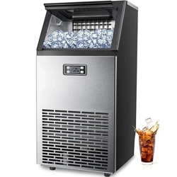
KNOW YOUR ICE MAKER
4
1
2
3
4
5
7
8
9
6
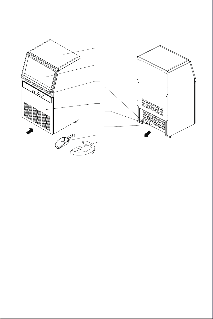
1. TOP COVER
2. DOOR CLOSED
3. CONTROL PANEL
4. DRAIN HOLE:Install the drain pipe here
5. FRONT PANEL
6. WATER INLET:Install the 1/4-inch PE tube here
7. POWER SUPPLY
8. SPOON
9. DRAIN PIPE
Air Out
Air In
5
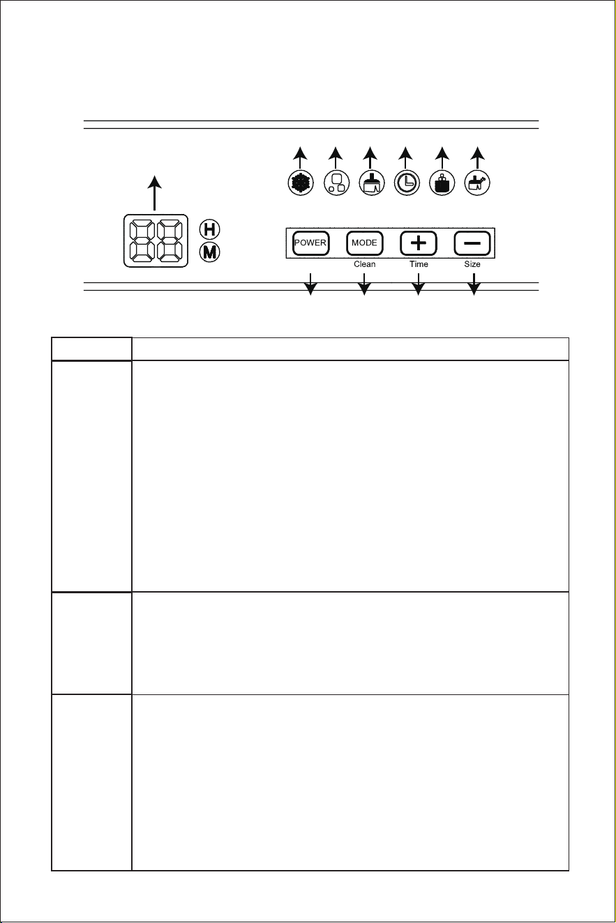
CONTROL PANEL & FUNCTIONS
No.
Description
1
Standby mode: “LED Screen” show “--”
1. Press “Power” : The unit enters into the ice-mak-
ing mode.
Ice making mode:
1. Press “Power” : The unit enters into the pre-shut
off mode.
[ pre-shut off mode: under the mode, if 00 shows
a figure ,the unit will shut off after the current
cycle. in this state, press “Power” can cancel the
mode; if not, unit shut off right now]
2. Press “Power”and hold for 3 sec : The unit will be
defrosting.
2
Clean mode :
1. (Under the mode )Press “Mode” and hold for 3
sec : The unit will exit clean mode.
2. Press “Mode” and hold for 3 sec : The unit
enters into the clean mode.
3
Timing function:[under standby mode or ice
making mode]
1. Press “+” and hold for 3 sec: activate the function
2. can adjust the valve by “+”or “-” ;
3. Wait 10sec the setting will be ok ,or press mode
to confirm it;
If the setting is done
1. Press “+”to show the set-valve 3sec;
2. Press “+”and hold for 3 sec : cancel the function
5 6 7 8 9 10
1 2 3 4
11
6
4
5
It will illuminate solidly under the “ice-making”
mode
It will flash under the pre-shutoff status.
Adjusting ice thickness :
1. Press “-” hold 3 sec: activate the function
2. Can adjust the valve by “+”or “-” ;
3. Wait 10sec the setting will be ok ,or press mode
to confirm it;
If the setting is done
1. Press “-” show the set-valve 3sec;
2. Press “-” hold 3 sec : cancel the function
6
The ice thickness indicator will illuminate solidly
under the mode of setting ice thickness.
7
8
The indicator of timer icon will illuminate solidly
under the mode of setting timer.
The clean indicator will illuminate solidly under the
clean mode.
9
The ice full indicator will illuminate solidly when
the ice basket is full.
10
The clean indicator will flash if the Ice Maker has
been operated for 3000 cycles or the ice-making
time exceeds 3 months. And the clean indicator
will turn off after the cleaning is performed.
11
LED Screen Display Description:
1.Ice-making mode: the countdown for
ice-shedding will be shown.
2.standby mode:show “--”
3.When the unit detects a malfunction, the code of
the malfunction will be shown.
4. Ice thickness:1 means bigger ICE ;0 means
default ICE ;-1 means smaller ICE
H: “H” icon will illuminate under the mode of
setting timer, which represents the precision for
setting hour.
M: “M” icon will illuminate under the mode of
setting ice thickness and the status of ice-shed-
ding countdown, which represents the precision
for the setting minute.

7
BEFORE FIRST USE
1. Unpack the unit, then check and make sure that all the accessories
including drain pipe and ice scoop etc. are complete. Please contact with
the client service department if any accessories are missing.
2. Please ensure the ice maker is placed on a stable table. Turn the four
black feet at the bottom of unit until the unit is placed stably.
3. The incline angle of the ice maker cabinet should not exceed 45°during
transportation or use. Do not turn the ice maker upside down. Doing so
could cause the compressor or refrigerating system to operate incorrect-
ly. Please allow time for the fluids in the compressor to settle after the ice
maker is moved or transported. Before using the ice maker for the first
time, please wait for 2 hours after the unit has been leveled and posi-
tioned in the proper place.
4. The unit must be placed on a dry and level surface with sufficient
ventilation and should not be exposed to direct sunlight. Leave a clear-
ance of 15cm around the air inlet and air outlet of the ice maker.
5. Do not fill the water reservoir with hot water, which may damage the ice
maker.
Maximum inlet water pressure: 827 kPa;
Minimum inlet water pressure: 207 kPa;
6. Do not use the unit in a very cold environment (lower than 46.4℉(8℃)).
7. Clean the unit by following the operation of “CLEANING AND MAINTE-
NANCE” before operating.
USING THE UNIT
1. Connect the drain pipe of the unit well and then fix it with a throat
clamp.
2. Connect a PE tube with a size of 1/4 inch with the unit. the new hose-sets
supplied with the appliance are to be used and that old hose-sets should
not be reused.
3. Connect the unit with a power source, the section of “00” in the display
shows “--”.
NOTE: The unit that has been moved should rest for 30 minutes before
being powered on.
4. Shortly press “Power” key, the unit starts to work.

8
5. The ice-shedding time for each ice-making cycle is indicated in a way
of countdown during the ice-making process.
6. The unit keeps making ice until the ice shovel can not reset automati-
cally, at that time, the ice basket is full and the ice full indicator illuminates
solidly.
7. Remove the ice in the ice basket with an ice spoon. After 15 seconds, the
unit works again.
8. When need to remove the ice, push the door until it is opened fully, and
then remove the ice according to your demand with the ice spoon.
9. When need to adjust the ice thickness, make the unit enter into the
mode of setting ice thickness and then adjust the ice thickness with the
keys “+” or “-”.
10. When need to make the unit start working at a preset time automati-
cally, make the unit enter into the mode of setting timer and then set the
auto-start time with the keys of “+” or “-”.
CLEANING AND MAINTENANCE
In order to keep the ice cubes fresh and the ice maker in good condition,
please perform the following cleaning process when the clean indicator
flashes.
NOTE: Please add the prepared detergent to the water tank manually
before cleaning.
1. Under the standby mode, hold and press “Power” key to enter into the
“Clean” mode, and the clean indicator illuminates solidly.
2. The unit starts to be rinsed repeatedly for about 15 minutes.
3. Continue to rinse with water for 4 minutes and then stop working for 1
minute.
4. Repeat Step 3 for 3 cycles.
5. The cleaning process is completed and then the unit goes back to the
standby mode (the cleaning process lasts for about 30 minutes).
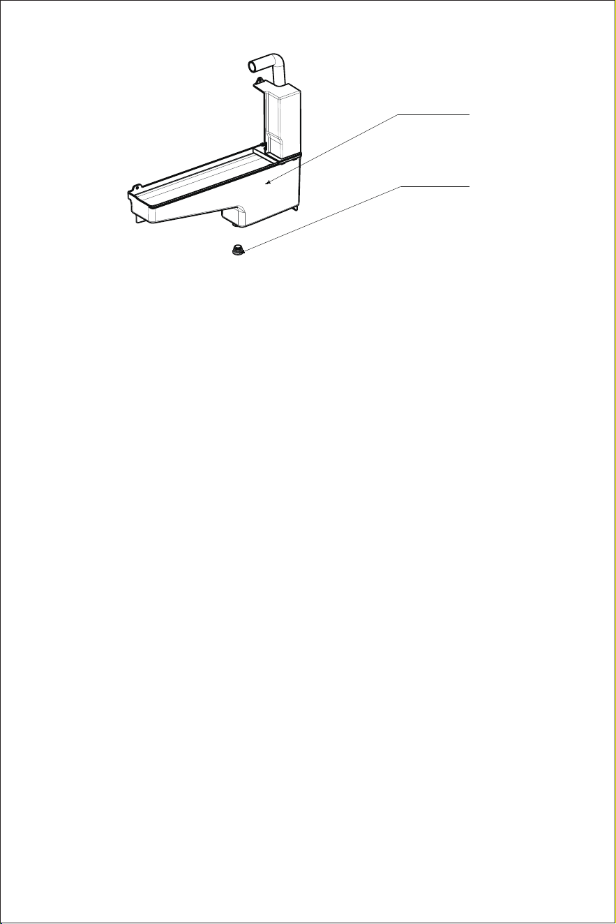
6. Unplug the drain plug manually.
7. Rinse the ice basket with warm water.
8. Install the drain plug well in position, and then the cleaning is complet-
ed.(STEP 6/7/8 is by consumer)
NOTE: Please empty the water in the unit, wipe it with a clean cloth and
store it well if the unit will not be used for a long time.
INFORMATION IN MANUAL
1. The piping material, pipe routing, and installation of ice maker shall
include protection from physical damage in operation and service, and
be in compliance with national and local codes and standards, such as
ANSI/ASHRAE 15, IAPMO Uniform Mechanical Code, ICC International
Mechanical Code, or CSA B52. All field joints shall be accessible for
inspection prior to being covered or enclosed;
2. protection devices, piping, and fittings shall be protected as far as
possible against
adverse environmental effects, for example, the danger of water collect-
ing and freezing in relief pipes or the accumulation of dirt and debris;
3. The return pipe of the ice maker adopts the method of heat exchange,
which reduces the risk of liquid shock;
4. Steel pipes and components shall be protected against corrosion with
a rustproof coating before applying any insulation;
5. Flexible pipe elements shall be protected against mechanical damage,
excessive stress by torsion, or other forces, and that they should be
checked for mechanical damage annually;
6. Precautions shall be taken to avoid excessive vibration or pulsation;
7. The amount of refrigerant to be filled according to the relevant instruc-
tions on the label provided by the manufacturer information for handling,
installation, cleaning, servicing and disposal of refrigerant;
8. Keep the vent clear;
9. That servicing shall be performed only as recommended by the manu-
facturer;
9
Water Tank
Drain Plug

10. That ducts connected to an appliance shall not contain a potential
ignition Source;
11. Procedures related to safety operations, such as breaking into the
refrigerating circuit, opening of sealed components, opening of ventilated
enclosures, can only be carried out by professional qualified personnel.
INFORMATION ON SERVICING
1. Prior to beginning work on systems containing FLAMMABLE REFRIGERANTS,
safety checks are necessary to ensure that the risk of ignition is mini-
mised.
2. Work shall be undertaken under a controlled procedure so as to mini-
mise the risk of a flammable gas or vapour being present while the work is
being performed.
3. All maintenance staff and others working in the local area shall be
instructed on the nature of work being carried out. Work in confined
spaces shall be avoided.
4. The area shall be checked with an appropriate refrigerant detector prior
to and during work, to ensure the technician is aware of potentially toxic
or flammable atmospheres. Ensure that the leak detection equipment
being used is suitable for use with all applicable refrigerants, i.e., nonspar-
king, adequately sealed, or intrinsically safe.
5. When performing hot work on refrigeration equipment or any related
parts, appropriate fire extinguishing equipment should be available. Dry
powder fire extinguisher or carbon dioxide fire extinguisher should be
placed near the charging area.
6. No person carrying out work in relation to a REFRIGERATING SYSTEM
which involves exposing any pipe work shall use any sources of ignition in
such a manner that it may lead to the risk of fire or explosion. All possible
ignition sources, including cigarette smoking, should be kept sufficiently
far away from the site of installation, repairing, removal and disposal,
during which refrigerant can possibly be released to the surrounding
space. Prior to work taking place, the area around the equipment shall be
surveyed to make sure that there are no flammable hazards or ignition
risks. "No Smoking" signs shall be displayed.
7. Ensure that the area is in the open or that it is adequately ventilated
before breaking into the system or conducting any hot work. A degree of
ventilation shall continue during the period that the work is carried out.
10

The ventilation should safely disperse any released refrigerant and
preferably expel it externally into the atmosphere.
8. Where electrical components are being changed, they shall be fit for
the purpose and to the correct specification. At all times, the manufactur-
er's maintenance and service guidelines shall be followed. If in doubt,
consult the manufacturer's technical department for assistance.
The following checks shall be applied to installations using FLAMMABLE
REFRIGERANTS:
a)the actual REFRIGERANT CHARGE is in accordance with the room size
within which the refrigerant containing parts are installed;
b)the ventilation machinery and outlets are operating adequately and
are not obstructed;
c)marking to the equipment continues to be visible and legible. Markings
and signs that are illegible shall be corrected.
d)components, unless the components are constructed of materials
which are inherently resistant to being corroded or are suitably protected
against being so corroded.
9. Repair and maintenance of electrical components shall include initial
safety checks and component inspection procedures. If a fault exists that
could compromise safety, then no electrical supply shall be connected to
the circuit until it is satisfactorily dealt with. If the fault cannot be correct-
ed immediately but it is necessary to continue operation, an adequate
temporary solution shall be used. This shall be reported to the owner of
the equipment, so all parties are advised.
Initial safety checks shall include:
a) that capacitors are discharged: this shall be done in a safe manner to
avoid possibility of sparking;
b) that no live electrical components and wiring are exposed while
charging, recovering or purging the system;
c) that there is continuity of earth bonding.
Repairs to sealed
1.During repairs to sealed components, all electrical supplies shall be
disconnected from the equipment being worked upon prior to any remov-
al of sealed covers, etc. If it is absolutely necessary to have an electrical
supply to equipment during servicing, then a permanently operating form
11

of leak detection shall be located at the most critical point to warn of a
potentially hazardous situation.
2.Particular attention shall be paid to the following to ensure that by
working on electrical components, the casing is not altered in such a way
that the level of protection is affected. This shall include damage to
cables, excessive number of connections, terminals not made to original
specification, damage to seals, incorrect fitting of glands, etc.
Ensure that the apparatus is mounted securely.
Ensure that seals or sealing materials have not degraded to the point that
they no longer serve the purpose of preventing the ingress of flammable
atmospheres. Replacement parts shall be in accordance with the manu-
facturer's specifications.
Repair to intrinsically safe components
1.Do not apply any permanent inductive or capacitance loads to the
circuit without ensuring that this will not exceed the permissible voltage
and current permitted for the equipment in use.
2.Intrinsically safe components are the only types that can be worked on
while living in the presence of a flammable atmosphere. The test appara-
tus shall be at the correct rating.
3.Replace components only with parts specified by the manufacturer.
Other parts can result in the ignition of refrigerant in the atmosphere from
a leak.
NOTE : The use of silicon sealant can inhibit the effectiveness of some
types of leak detection equipment. Intrinsically safe components do not
have to be isolated prior to working on them.
Cabling
Check that cabling will not be subject to wear, corrosion, excessive
pressure, vibration, sharp edges, or any other adverse environmental
effects. The check shall also take into account the effects of aging or
continual vibration from sources such as compressors or fans.
Detection of flammable refrigerants
Under no circumstances shall potential sources of ignition be used in the
search for or detection of refrigerant leaks. A halide torch (or any other
detector using a naked flame) shall not be used.
1.Electronic leak detectors may be used to detect refrigerant leaks but, in
the case of FLAMMABLE REFRIGERANTS, the sensitivity might not be ade-
quate, or might need recalibration. (Detection equipment shall be
calibrated in a refrigerant-free area.) Ensure that the detector is not a
potential source of
12

ignition and is suitable for the refrigerant used. Leak detection equipment
shall be set at a percentage of the LFL of the refrigerant and shall be
calibrated to the refrigerant employed, and the appropriate percentage
of gas (25 % maximum) is confirmed.
2.Leak detection fluids are applicable.
NOTE: Examples of leak detection fluids are
-bubble method,
-fluorescent method agents.
If a leak is suspected, all naked flames shall be removed/extinguished.
If a leak of refrigerant is found which requires brazing, all of the refrigerant
shall be refrigerants from the system, or isolated (by means of shut off
valves) in a part of the system remote from the leak.
Removal and evacuation
When entering the refrigerant circuit for servicing or for any other purpose,
the following procedures should be followed for combustible refrigerants:
a) safely remove refrigerant following local and national regulations;
b) purge the circuit with inert gas;
c) open the circuit by cutting or brazing.
The refrigerant charge shall be recovered into the correct recovery
cylinders if venting is not allowed by local and national codes. For appli-
ances containing flammable refrigerants, the system shall be purged with
oxygen-free nitrogen to render the appliance safe for flammable refriger-
ants. This process might need to be repeated several times. Compressed
air or oxygen shall not be used for purging refrigerant systems.
For appliances containing flammable refrigerants, refrigerants purging
shall be achieved by breaking the vacuum in the system with oxygen-free
nitrogen and continuing to fill until the working pressure is achieved, then
venting to atmosphere. When the final oxygen-free nitrogen charge is
used, the system shall be vented down to atmospheric pressure to enable
work to take place.
Ensure that the outlet for the vacuum pump is not close to any potential
ignition sources and that ventilation is available.
Charging procedures
In addition to conventional charging procedures, the following require-
ments shall be followed.
a) Ensure that contamination of different refrigerants does not occur
when using charging equipment. Hoses or lines shall be as short as
possible to minimise the amount of refrigerant contained in them.
b) Cylinders shall be kept in an appropriate position according to the
instructions.
13

c) Ensure that the REFRIGERATING SYSTEM is earthed prior to charging the
system with refrigerant.
d) Label the system when charging is complete (if not already).
e) Extreme care shall be taken not to overfill the REFRIGERATING SYSTEM.
Prior to recharging the system, it shall be pressure-tested with the appro-
priate purging gas. The system shall be leak-tested on completion of
charging but prior to commissioning. A follow-up leak test shall be carried
out prior to leaving the site.
Decommissioning
Before carrying out this procedure, it is essential that the technician is
completely familiar with the equipment and all its details. It is recom-
mended good practice that all refrigerants are recovered safely. Prior to
the task being carried out, an oil and refrigerant sample shall be taken in
case analysis is required prior to to the re-use of recovered refrigerant. It
is essential that electrical power is available before the task is com-
menced.
a) Become familiar with the equipment and its operation.
b) Isolate the system electrically.
c) Before attempting the procedure, ensure that:
i) mechanical handling equipment is available, if required, for handling
refrigerant cylinders;
ii) all personal protective equipment is available and being used correct-
ly;
iii) the recovery process is supervised at all times by a competent person;
iv) recovery equipment and cylinders conform to the appropriate stan-
dards.
d) Pump down refrigerant system, if possible.
e) If a vacuum is not possible, make a manifold so that refrigerant can be
removed from various parts of the system.
f) Make sure that cylinder is situated on the scales before recovery takes
place.
g) Start the recovery machine and operate in accordance with instruc-
tions.
h) Do not overfill cylinders (no more than 80 % volume liquid charge).
i) Do not exceed the maximum working pressure of the cylinder, even
temporarily.
j) When the cylinders have been filled correctly and the process complet-
ed, make sure that the cylinders and the equipment are removed from
site promptly and all isolation valves on the equipment are closed off.
k) Recovered refrigerant shall not be charged into another REFRIGERATING
SYSTEM unless it has been cleaned and checked.
14

Labelling
Equipment shall be labelled stating that it has been de-commissioned
and emptied of refrigerant. The label shall be dated and signed. For
appliances containing FLAMMABLE REFRIGERANTS, ensure that there are
labels on the equipment stating the equipment contains FLAMMABLE
REFRIGERANT.
Recovery
When removing refrigerant from a system, either for servicing or decom-
missioning, it is recommended good practice that all refrigerants are
removed safely.
When transferring refrigerant into cylinders, ensure that only appropriate
refrigerant recovery cylinders are employed. Ensure that the correct
number of cylinders for holding the total system charge is available. All
cylinders to be used are designated for the recovered refrigerant and
labelled for that refrigerant (i.e., special cylinders for the recovery of
refrigerant). Cylinders shall be complete with pressure-relief valve and
associated shut-off valves in good working order. Empty recovery cylin-
ders are evacuated and, if possible, cooled before recovery occurs.
The recovery equipment shall be in good working order with a set of
instructions concerning the equipment that is at hand and shall be
suitable for the recovery of all appropriate refrigerants including, when
applicable, FLAMMABLE REFRIGERANTS. In addition, a set of calibrated
weighing scales shall be available and in good working order. Hoses shall
be complete with leak-free disconnect couplings and in good condition.
Before using the recovery machine, check that it is in satisfactory working
order, has been properly maintained and that any associated electrical
components are sealed to prevent ignition in the event of a refrigerant
release. Consult manufacturer if in doubt.
The recovered refrigerant shall be returned to the refrigerant supplier in
the correct recovery cylinder, and the relevant waste transfer note
arranged. Do not mix refrigerants in recovery units and especially not in
cylinders.
If compressors or compressor oils are to be removed, ensure that they
have been evacuated to an acceptable level to make certain that FLAM-
MABLE REFRIGERANT does not remain within the lubricant. The evacuation
process shall be carried out prior to returning the compressor to the
suppliers. Only electric heating to the compressor body shall be
employed to accelerate this process. When oil is drained from a system, it
shall be carried out safely.
15
TROUBLESHOOTING
Note 1. If unit shows Error【E1/E2/E3/E5】, the unit can recover to standby
mode by pressing the “Power” Key ;
2. If unit shows E1,the unit can recover to “Making ice mode ”by pressing
the “+” Key.
TEST ROOM CLIMATE DEFINITION
Tests shall be carried out in one of the climate classes according to Table
1.During the test, the test room shall be capable of maintaining values of
temperature and humidity within ±1 °C of the temperature and ±5 units of
the relative humidity percentage figures at the specified climate measur-
ing point(s). The exception to this is test-room climate class 3, for which
the tolerance of the relative humidity is instead ±3 units.
16
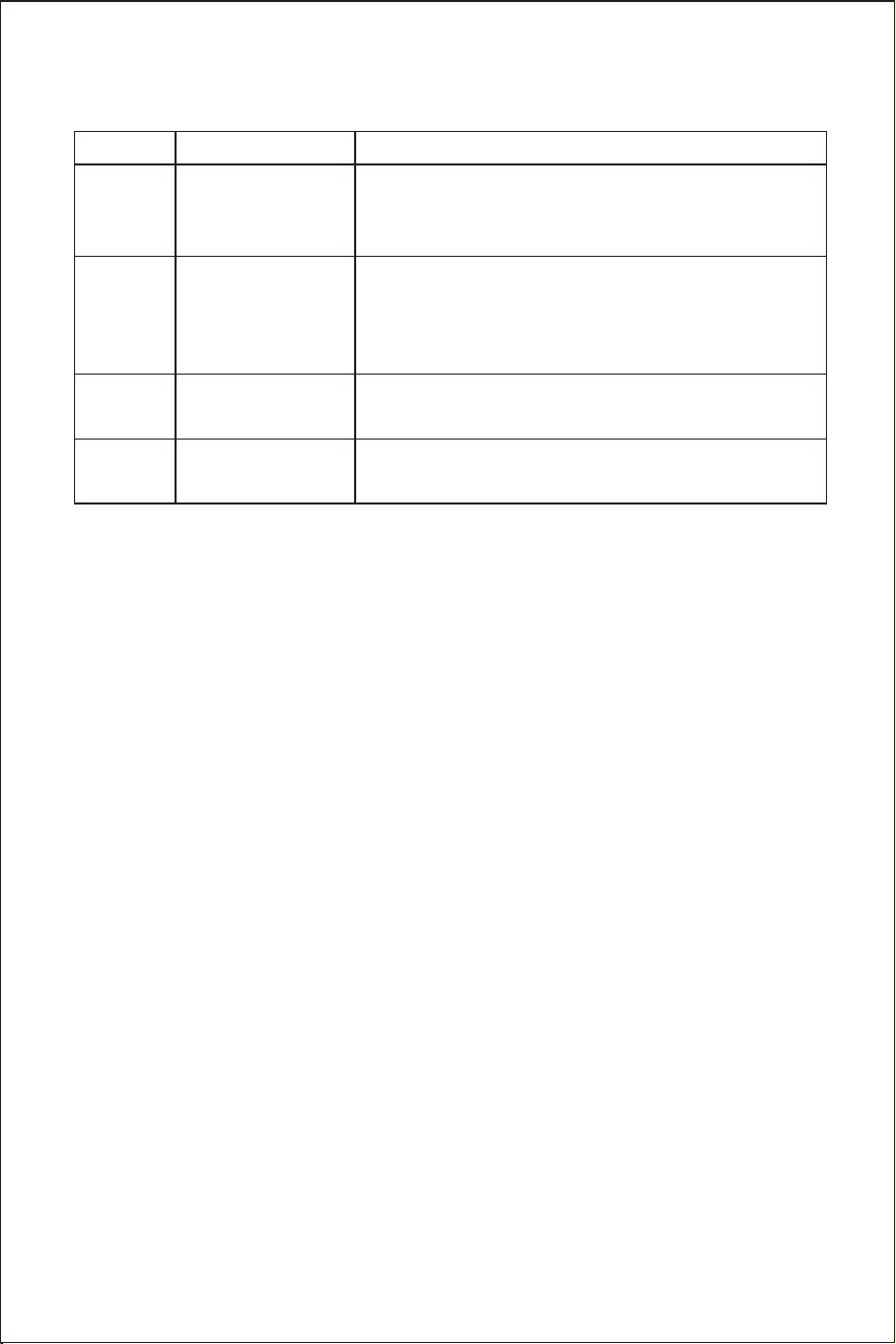
problems possible causes
solutions
E1
No water 1. Check the water inlet valve and float.
2. Check the drain plug for any water
leakage.
E2
Malfunction of
solenoid valve
1. Check the solenoid valve.
2. Check the water pump.
3. Check the refrigeration system for any
leakage.
E3
NTC
malfunction
Replace NTC.
E5
Malfunction
of float switch
Replace the float switch.
Test room
climate class
Dry bulb
temperature
℉
Relative
humidity%
Dew point℉
Water vapour
mass in dry
air g/kg
0 68 50 48.74 7.3
1 60.8 80 54.68 9.1
8 75.2 55 57.92 10.2
2 71.6 65 59.36 10.8
3 77 60 62.06 12.0
4 86 55 68 14.8
6 80.6 70 69.98 15.8
5 104
40 75.02 18.8
7 95 75 86 27.3
Table 1—Climate classes
NOTE The water vapour mass in dry air is one of the main points influenc-
ing the performance and the energy consumption of the cabinets. There-
fore the order of the climate class in the table is based on the water
vapour mass column. See also Annex B (IS0 23953-2:2015)to compare
lab and store conditions.
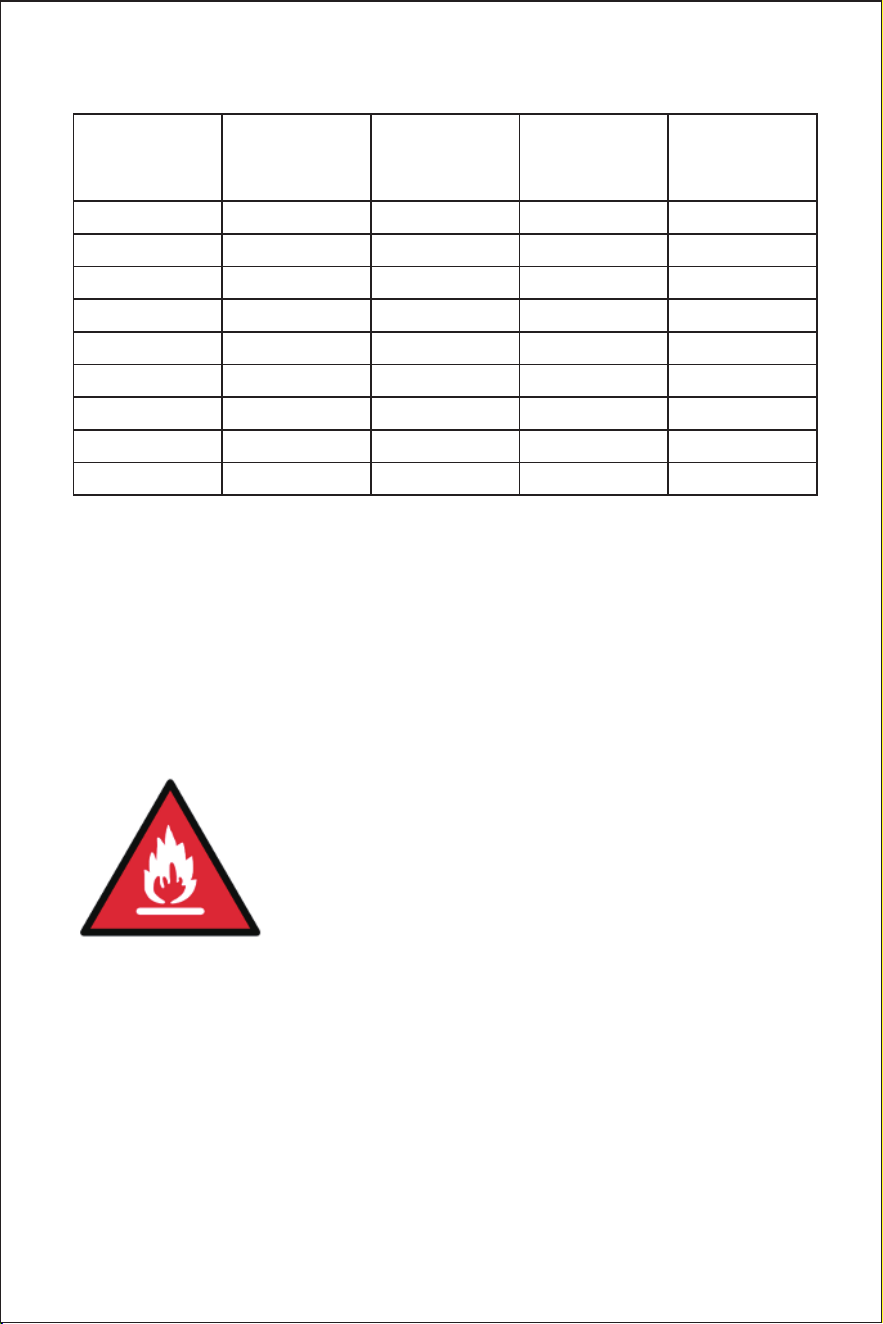
WARNING SIGN DEFINITION
Warning sign ISO 7010-W021 (2011-05)
Warning: Risk of fire/fiammable materials.
17
TECHNICAL PARAMETERS
ITEM NO.: Z4790
Model NO.: IMC9000-UL
Test room climatic classes: 0,1,2,3,4,5,6,7 or 8
Electrical protection class: I
Voltage/Frequency: 120V/60Hz
Total input power: 380W
Refrigerant: R290/58g
Foaming agent: Cyclopentane
18
Net weight: 25kg
Housing: SUS430
Unit size (W*D*H): 17.52*15.87*31.30inch
Water supply temperature: 41-95℉(5-35℃)