INSTALLATION AND OPERATING INSTRUCTIONS
WARNING: If the information in this manual is not followed exactly, a re or
explosion may result causing property damage, personal injury, or loss of life.
Do not store or use gasoline or other ammable vapors and liquids or other
combustible materials in the vicinity of this or any other appliance.
WHAT TO DO IF YOU SMELL GAS:
• Do not try to light any appliance.
• Do not touch any electrical switch; do not use any phone in your building.
• Immediately call your gas supplier from a neighbor’s phone. Follow the gas
supplier’s instructions.
• If you cannot reach your gas supplier, call the re department.
Installation and service must be performed by a qualied
installer, service
agency or the gas supplier.
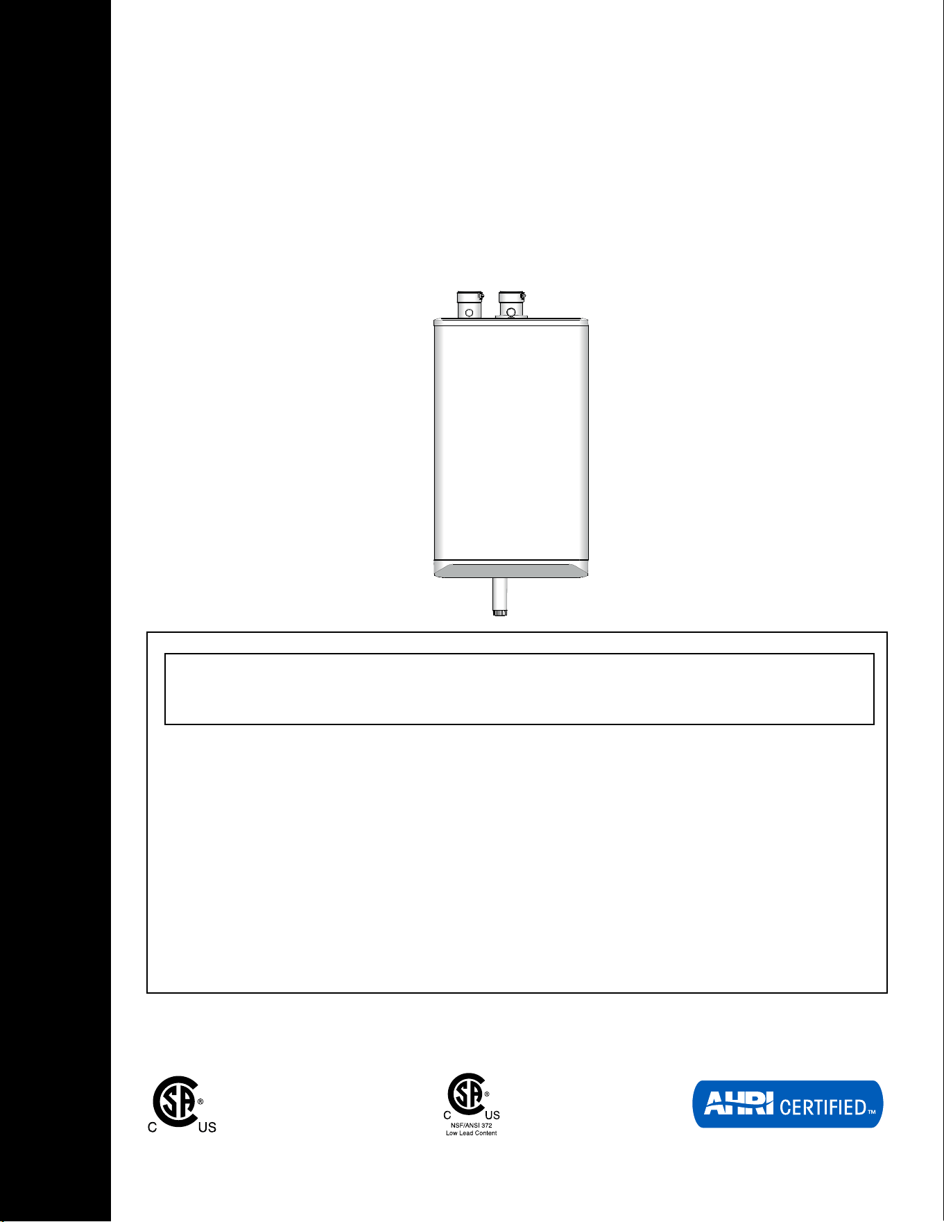
HIGH EFFICIENCY CONDENSING
TANKLESS WATER HEATER
199,000 Btu/hr Model
(Natural Gas or Propane)

INSTALLATION AND OPERATION INSTRUCTIONS
2
TANKLESS WATER HEATER 199
SAFETY CONSIDERATIONS
Installation, start-up and servicing of the unit must be done with due
care and attention, and must only be performed by competent, qualied,
licensed and trained heating technicians. Failure to read and comply with
all instructions and applicable National and local codes may result in
hazardous conditions that could result in property damage and injury to
occupants which in extreme cases might result in death.
HAZARDS & PRECAUTIONS
Supplied with the unit - The unit is shipped with an accessory parts kit
consisting of the following items:
• 1 x Wall Mounting Kit- Part # P-081344
• 1 x Condensate trap assembly
• 1 x Documentation set
• 1 x Propane Conversion Kit: Part # P-081014
WARNING
If the information in this
manual is not followed
exactly, a re or explosion
may result causing property
damage, personal injury, or
loss of life.
WARNING
Points out a potentially
hazardous situation which
must be avoided to prevent
serious injury or death.
CAUTION
Points out a potentially
hazardous situation which
must be avoided to prevent
possible moderate injury and/
or property damage
NOTE
Points out installation,
maintenance and operation
details that will result in
enhanced eciency, longevity
and proper operation of your
unit.
DANGER
Points out an imminently
hazardous situation which
must be avoided in order to
prevent serious injury or
death.
BEST PRACTICES
Points out recommendations
for better installation.
3
INSTALLATION AND OPERATING INSTRUCTIONS
TANKLESS WATER HEATER 199
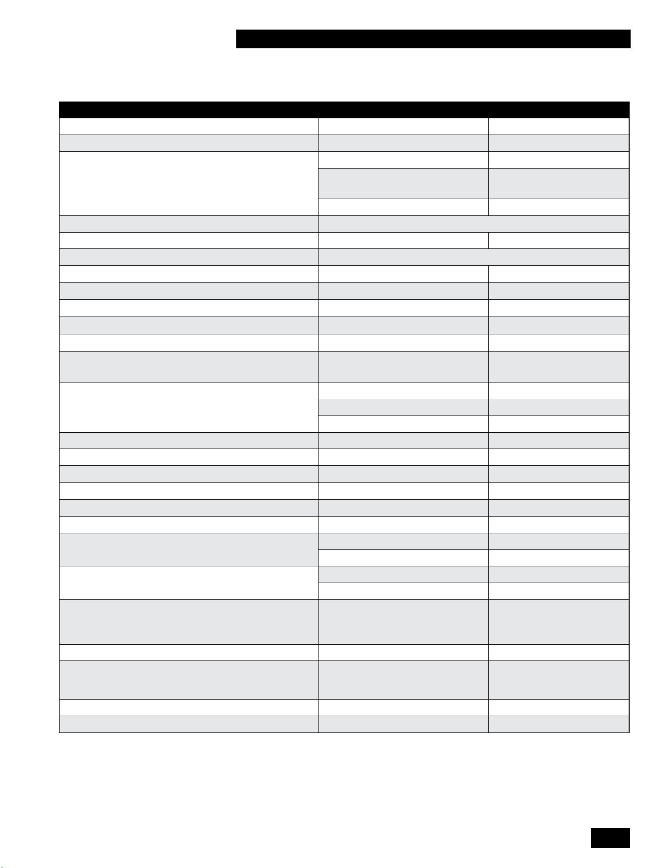
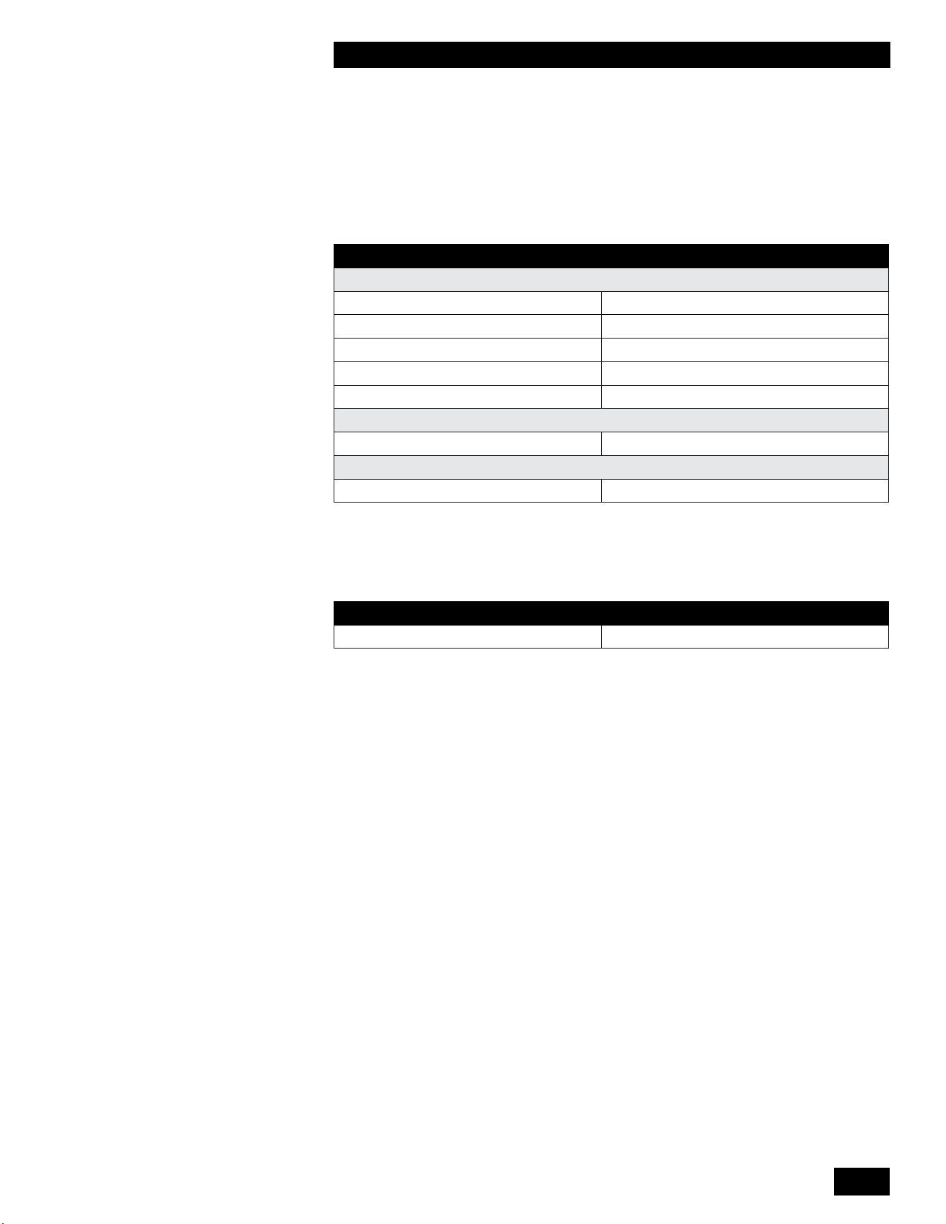
SPECIFICATION 199,000 BTU
Input (Natural Gas or Propane*) - MBH 28.5-199
U.E.F 0.9
DHW Flow Rate - GPM (LPM) 35°F (19°C) Temp Rise 10.1 (38)
45°F (25°C) Temp Rise 7.9 (30)
67°F (36°C) Temp Rise 5.4 (20)
Dimensions - in/mm 17.7 x 29.8 x 10.9 (450 x 757 x 277)
Weight (empty) - lbs/Kg 68 / 31
Installation Type Indoor only wall-hung
Venting Type Forced Draft Direct Vent
Electronic Ignition
Water Pressure - psig 40 - 150
Min Gas Pressure (Nat. Gas or Propane*) - inch w.c. 4
Max Gas Pressure (Nat. Gas or Propane*) - inch w.c. 14
Minimum Flow Rate to activate DHW heating -
GPM (LPM)
0.5 (1.9)
Connection Sizes Cold Water Inlet 3/4" Male NPT
Hot Water Outlet 3/4" Male NPT
Gas Inlet 3/4" Male NPT
Pressure Vessel water content – USG/Liters 0.19 / 0.72
Ambient Temperature – Low (°F/°C) 32 / 0
Ambient Temperature – High (°F/°C) 122 / 50
Max relative humidity (non-condensing) 90%
Min water Temperature – Domestic Hot Water (°F/°C) 105 / 40
Max water Temperature – Domestic Hot Water (°F/°C) 149 / 65
Power Supply Main Supply 120Vac, 60Hz
Watts @ full re 100 watts
Materials Casing Painted steel and plastic
Heat Exchangers Copper tubes in AL block
Venting
Canada venting must meet ULC S636
Intake & Exhaust 2" or 3" PVC, CPVC,
Polypropylene
Venting Clearances 0" to combustibles
Safety Devices Flame Proving module, Flue
Gas Temperature Sensor,
Protective fuse
Certied design ANSI Z21.10.3 • CSA 4.3
Freeze Protection Yes
*UnitsshipconguredforNaturalGas(NG)withaPropane(LP)conversionkitincluded.ConvertinganLPunitbacktoNGrequiresthecertiedNGconversionkitthat
can be ordered separately.
SPECIFICATIONS
INSTALLATION AND OPERATION INSTRUCTIONS
4
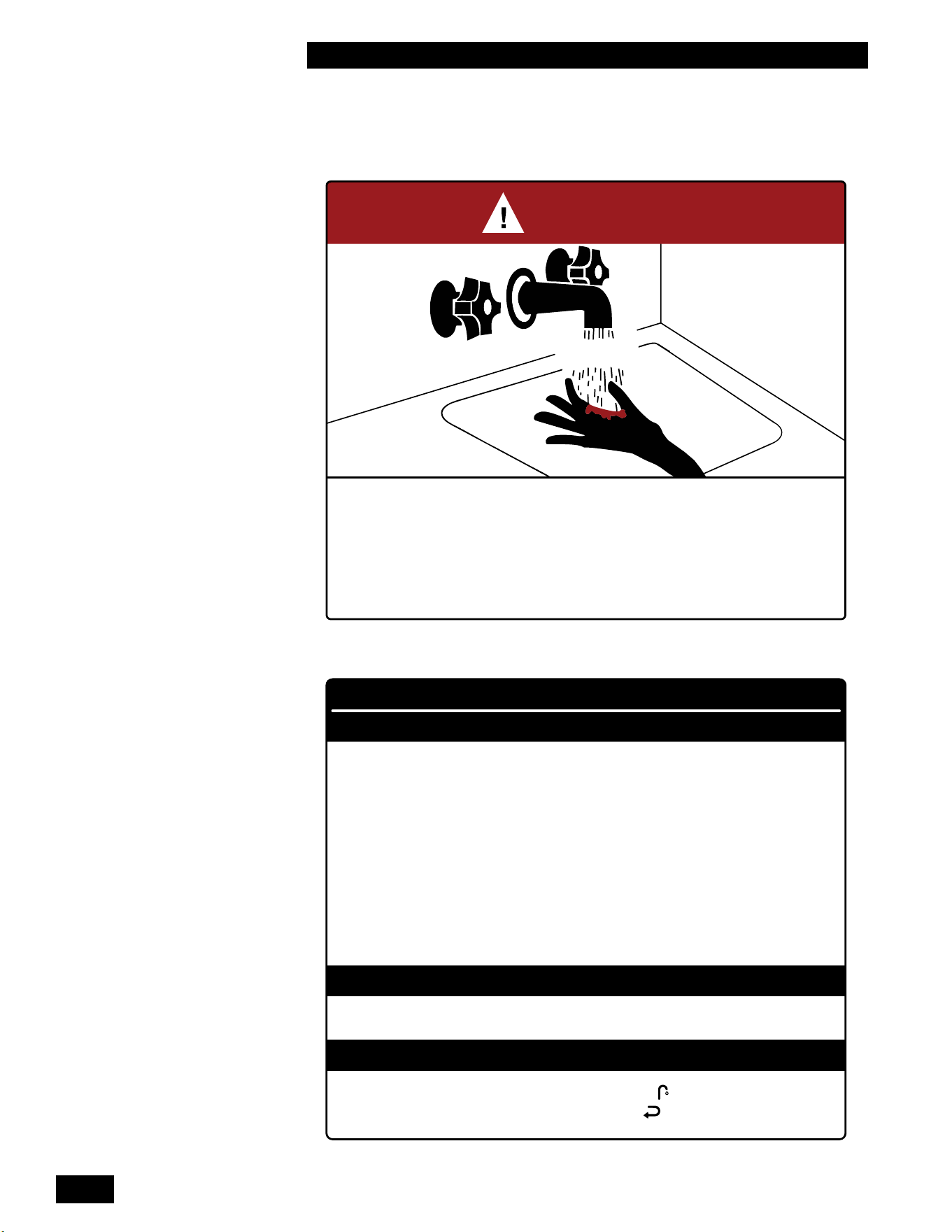
TANKLESS WATER HEATER 199
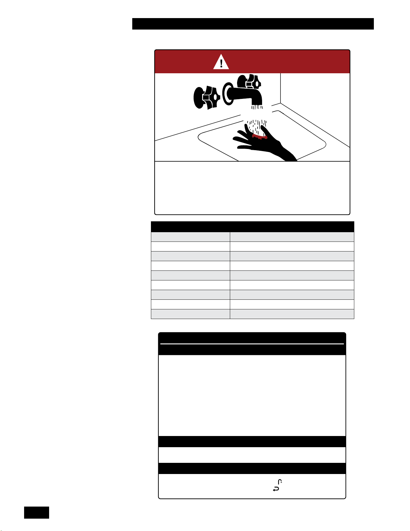
BURN
HOT
DANGER
°
Water temperature over 125°F (52°C) can cause severe burns instantly
or death from scalds.
°
Children, disabled, and elderly are at highest risk of being scalded.
°
See instruction manual before setting temperature at water heater.
°
Feel water before bathing or showering.
°
Temperature limiting valves are available, see manual.
WARNING
CAUTION
WATER HEATER INSTALLATION GUIDELINES
ADJUSTABLE TEMPERATURE SETTING
°
Hotter water increases the risk of scald injury. Before changing the temperature setting, see
instruction manual.
°
This unit must be installed in accordance with local codes, if any; if not follow the National
Fuel Gas Code, ANSI Z223.1/NFPA 54, or the Natural Gas and Propane Installation Code,
CAN/CSA B149.1, as applicable.
°
Failure to correctly install and operate this appliance can result in severe personal injury
or death.
°
The unit shall have a pressure relief valve installed within 6" [152mm] of the DHW HOT
outlet connection.
Refer to the unit’s User Manual before operating the relief valve.
°
The unit requires a pressure relief valve identified with the ASME V or HV symbol and
set to relieve at or below 150psi of domestic water pressure and a minimum relieving capacity
of 199,000 Btu/hr with 3/4" NPT threads. For safe operation of the unit, the relief valve
must not be removed from its designated point of installation or plugged.
°
Read and follow warnings and instructions.
°
Touch the panel above the white dot , then touch the Faucet . Adjust the water temperature
with the Plus + and Minus – then touch the Return button to save the changes.
TIME/TEMPERATURE RELATIONSHIP IN SCALDS
WATER TEMPERATURE TIME TO PRODUCE A SERIOUS BURNTIME TO PRODUCE A SERIOUS BURN
120°F (49°C) More than 5 minutes
125°F (52°C) 1 ½ to 2 minutes
130°F (54°C) About 30 seconds
135°F (57°C) About 10 seconds
140°F (60°C) Less than 5 seconds
145°F (63°C) Less than 3 seconds
150°F (66°C) About 1 ½ seconds
155°F (68°C) About 1 second
Table courtesy of Shriners Burn Institute

5
INSTALLATION AND OPERATING INSTRUCTIONS
TANKLESS WATER HEATER 199
CONTENTS
1.0 INSTALLATION ..........................................1-1
1.1 GENERAL........................................................1-1
1.2 CODE REQUIREMENTS ............................................1-3
1.3 LOCATION .......................................................1-3
1.3.1 Mobile Home Installations ........................................1-4
1.3.2 Removing/installing the front panel .................................1-5
1.4 EXHAUST VENTING AND AIR INTAKE .................................1-6
1.4.1 Applications ..................................................1-10
1.4.2 Exhaust Vent Material ..........................................1-10
1.4.3 Vent Travel ...................................................1-10
1.4.4 Venting Passage Through Ceiling and Floor .........................1-12
1.4.5 Rooftop Vent Termination........................................1-12
1.4.6 Sidewall Vent Termination .......................................1-14
1.4.7 “Direct Vent” Combustion Air Intake Piping ..........................1-18
1.4.8 “Indoor Air” Combustion Air Intake .................................1-19
1.4.9 Closet Installations .............................................1-19
1.5 CONDENSATE REMOVAL..........................................1-20
1.5.1 Condensate Trap ..............................................1-20
1.5.2 Installing the Condensate Trap....................................1-20
1.5.3 Further Installation Details . . . . . . . . . . . . . . . . . . . . . . . . . . . . . . . . . . . . . . . 1-21
1.6 WATER AND SPACE HEATING APPLICATION ..........................1-22
1.7 DOMESTIC HOT WATER SYSTEM ...................................1-24
1.7.1 Domestic Hot Water System .....................................1-25
1.7.2 Domestic Hot Water Piping ......................................1-26
1.7.3 Tankless Domestic Hot Water with a Storage Tank ....................1-27
1.8 GAS PIPING .....................................................1-29
1.9 ELECTRICAL CONNECTIONS ......................................1-30
1.9.1 120VAC Line Voltage Hook-up....................................1-30
1.9.2 Accessing Controller Terminal Strip ................................1-30
1.9.3 Power Quality and Electrical Protection ............................1-30
2.0
UNIT SYSTEM OPERATION .....................................2-1
2.1 GENERAL........................................................2-1
2.2 CONTROL .......................................................2-2
2.3 INSTALLER INTERFACE ............................................2-2
2.3.1 Turning Appliance ON/OFF .......................................2-2
2.3.2 Programming Mode.............................................2-3
2.4 TANKLESS DOMESTIC HOT WATER MODES ...........................2-4
2.4.1 Tankless Domestic Hot Water - Standard and ECO Comfort Modes ........2-4
2.5 SEQUENCE OF OPERATION ........................................2-5
2.6 ACCESSING THE INFORMATION MENU ...............................2-6
2.7 RESETTING THE MAINTENANCE COUNTER ...........................2-8
3.0 STARTUP & COMMISSIONING ..............................3-1
3.1 LIGHTING & SHUTTING DOWN THE UNIT .............................3-1
3.2 PRIOR TO START-UP ..............................................3-2
3.2.1 Pre-Ignition Checks .............................................3-2
3.2.2TestIgnitionSafetyShuto .......................................3-2

INSTALLATION AND OPERATION INSTRUCTIONS
6
TANKLESS WATER HEATER 199
3.3 COMMISSIONING .................................................3-2
3.4 FUEL CONVERSION ...............................................3-4
3.4.1 Gaining access to combustion chamber, burner removal instructions .......3-5
4.0 MAINTENANCE..........................................4-1
4.1 WATER HEATER MAINTENANCE.....................................4-1
4.1.1 General Care ..................................................4-1
4.1.2 Inspection.....................................................4-1
4.1.3 Venting .......................................................4-1
4.1.4 Condensate Trap ...............................................4-1
4.1.5 Burner . . . . . . . . . . . . . . . . . . . . . . . . . . . . . . . . . . . . . . . . . . . . . . . . . . . . . . . 4-1
4.1.6 Heat Exchanger . . . . . . . . . . . . . . . . . . . . . . . . . . . . . . . . . . . . . . . . . . . . . . . . 4-2
4.1.7 Gas Piping ....................................................4-2
4.1.8 Control Module.................................................4-2
4.1.9 Freeze Protection...............................................4-2
4.1.10 Relief Valve - Maintenance and Testing .............................4-2
4.1.11 Domestic Hot Water System......................................4-2
4.1.12 DHW Coil cleaning instructions...................................4-3
4.1.13 DHW Filter cleaning instructions ..................................4-4
4.1.14 Fan removal instructions ........................................4-4
4.1.15 Fan installation instructions ......................................4-4
4.1.16 Cleaning the Condensate Trap....................................4-5
4.1.17 Reset the Maintenance Counter...................................4-7
4.1.18 Winterization..................................................4-7
5.0 TROUBLESHOOTING .....................................5-1
5.1 PRELIMINARY CHECKS ............................................5-1
5.2 ELECTRONIC COMPONENTS .......................................5-2
5.2.1 Temperature Sensors............................................5-2
5.2.2 Cabinet Sensors................................................5-2
5.2.3 Flue Gas Temperature Sensor .....................................5-3
5.2.4 Domestic Hot Water Flow Sensor ..................................5-3
5.2.5 Domestic Hot Water Sensor.......................................5-3
5.2.6 Domestic Hot Water Bypass Valve..................................5-4
5.2.7 Domestic Cold Water Sensor ......................................5-4
5.2.8 Fan/Blower ....................................................5-4
5.3 FAULTS AND NOTIFICATIONS .......................................5-5
5.3.1 Fault Codes ...................................................5-5
5.3.2NoticationCodes ..............................................5-9
5.4 OTHER FAULTS ..................................................5-10
5.4.1 No domestic hot water (DHW) . . . . . . . . . . . . . . . . . . . . . . . . . . . . . . . . . . . . 5-10
5.4.2 Domestic hot water does not reach the correct temperature .............5-11
5.4.3 Burner ignites loudly............................................5-11
5.4.4 Burner resonates ..............................................5-11
6.0 REPLACEMENTS KITS ....................................6-1
7.0 WIRING DIAGRAMS ......................................6-2
INSTALLATION & COMMISSIONING REPORT..............................6-4
SERVICE RECORD ...................................................6-5
NOTES ............................................................6-6

7
INSTALLATION AND OPERATING INSTRUCTIONS
TANKLESS WATER HEATER 199
PRE-INSTALLATION CHECK
Carefully consider clearances and access, vent travel and termination, gas
supply, condensate removal and combustion air supply.
Consider the following:
• Install the water heater in areas where the combustion air source is free of
contamination. Exposure to corrosive chemical fumes such as chlorinated
and/oruorinatedhydrocarbonscanreducethelifeofaunit.Cleaners,
bleaches,airfresheners,refrigerants,aerosolpropellants,dry-cleaninguids,
de-greasers and paint-removers all contain vapors that can form corrosive
acidcompoundswhenburnedinagasame.Avoidairbornechloridessuch
as those released with the use of laundry detergents.
• Locate the unit where water leakage will not result in damage to the area (for
example,donotinstallabovecarpeting).Ifyoucannotndasuitablelocation,
installadrainpanwithanadequatedrainundertheappliance.
• At a new construction site, or during renovations, protect the unit from drywall
dust or other construction related contaminants.
○ Ensure combustion air is drawn from a CLEAN source (e.g. outdoors).
○ Isolate the unit from interior dust sources.
• When the unit is in operation, assess the impact of the steam plume normally
experienced at the exhaust terminal of a condensing water heater. Generally,
intake and exhaust pipes should terminate at a rooftop or wall location free of
obstructions. Water heater condensate is corrosive. Protective measures must
be taken to prevent corrosion damage to metal roofs or other metal building
components in contact with the condensate. Keep exhaust plumes well
away from all building air intakes including those of neighboring properties
byfollowingallrequirementsofthejurisdictionhavingauthorityandthis
installation manual.
• Place the exhaust outlet so it reaches 12" minimum above the down-turned
intaketoavoiduegascontaminationofthecombustionair.
• For sidewall venting options: Both the inlet and exhaust terminations must
be located on the same side of the building. You can elevate both pipes
in“periscopestyle”afterpassingthemthroughthewalltogainrequired
clearance above grade and snow level.
• Examine the condensate outlet to ensure proper disposal of condensate
will occur during operation. A condensate neutralizer must be installed if the
condensatewillowintoadrainsubjecttocorrosion.
• Ensure that the pressure relief valve is installed with no valves or other
means of isolation between its inlet and the unit. Pipe the relief valve with
unobstructed piping (minimum 3/4" diameter) to a safe discharge location.
• Inlocationswherepowersupplyqualityvariesorisunstable,consider
installing surge protection and power conditioners (up to and including battery
back-up uninterrupted power supply devices).
• Ensure the domestic hot water demands are considered before purchasing
the Tankless Water Heater. You may need to add a storage tank.
CAUTION
Care must be taken to
properly size the unit for
its intended use. Prolonged
full-re run time, over-
sizing or under-sizing,
and incorrect ow rates
through the unit can lead
to increased maintenance
costs, equipment stress and
premature failure.
WARNING
Do not use this unit if any
part has been under water.
Immediately call a qualied
service technician to inspect
the unit and to replace any
part of the control system and
any gas control that has been
under water.
DANGER
Should overheating occur
or the gas supply fails to
shut o, do not turn o or
disconnect the electrical
supply to the pump. Instead
shut o the gas supply at
a location external to the
appliance.

INSTALLATION AND OPERATION INSTRUCTIONS
8
TANKLESS WATER HEATER 199
This page is intentionally left blank.
1-1
INSTALLATION AND OPERATING INSTRUCTIONS
TANKLESS WATER HEATER 199
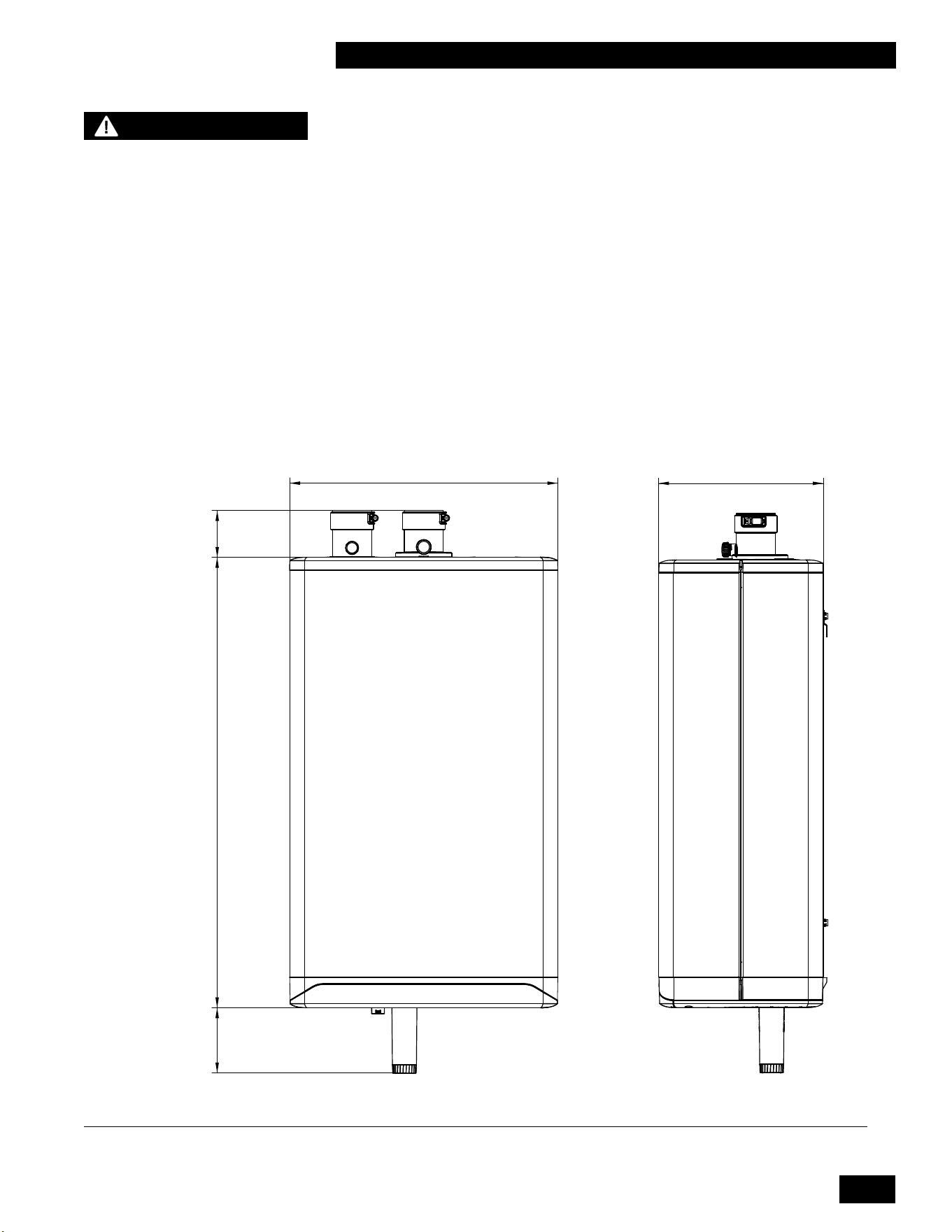
17.7in
[450mm]
3.1in
[79mm]
29.8in
[757mm]
4.3in
[109mm]
FRONT
1.0 INSTALLATION
1.1 GENERAL
ThisHighEciencyCondensingtanklesswaterheaterisdesignedtobeusedfor
domestic (residential) purposes. Domestic use is considered to be an average
annual gas usage of less than 4000 m
3
(140,000 ft
3
) for natural gas or 5680 L
(1500 US gallons) for propane. The products are fully condensing units with
variable input ranges (see specication chart - page 3). The units are approved
as “Category IV” vented appliances using Direct Vent (sealed combustion).
Figures 1a and 1b show outer case dimensions and piping. Use this diagram to
ndasuitablelocationfortheunit.See also Section 1.3 Location.
Figure 1a: Dimensions / Connections for Tankless Water HeaterTankless Water Heater
10.9in
[278mm]
SIDE
NOTE
Commercial use is allowed
only if the unit is regularly
maintained, and the heat
exchanger is cleaned at least
once a year, or more often if
the unit is experiencing heavy
use. Note: If the appliance is
serving only one residential
home in a multi-family
building, then the appliance
shall be considered used for
residential use.
INSTALLATION AND OPERATION INSTRUCTIONS
1-2
TANKLESS WATER HEATER 199
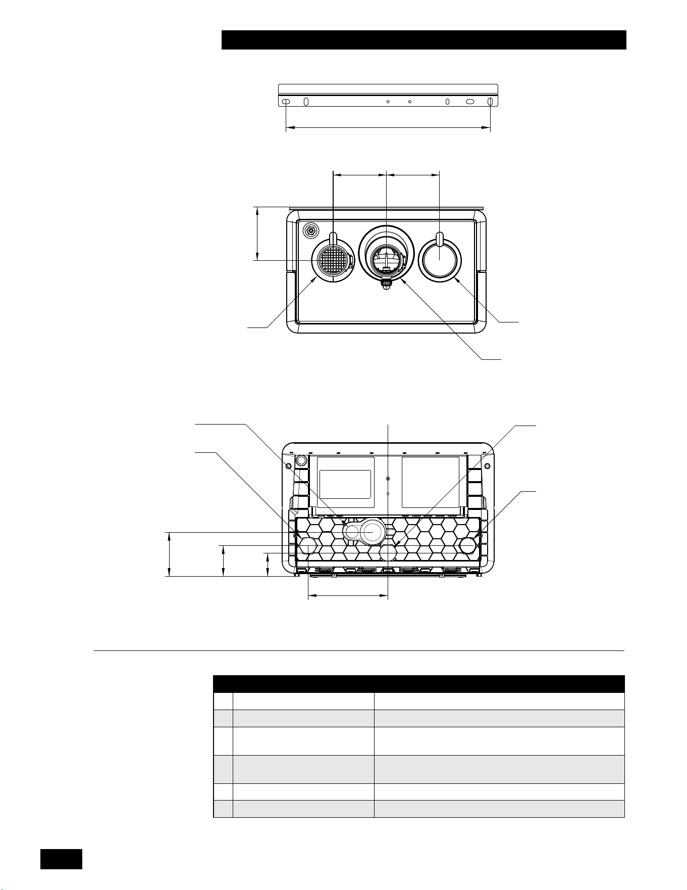
4.7in
[120mm]
4.7in
[120mm]
TOP
B (ALTERNATE)
A
B
4.5in
[114mm]
B (ALTERNATE)
B
6.7in
[170mm]
BOTTOM
3.7in
[95mm]
2.6in
[65mm]
2in
[50mm]
D
F
E
C
C
L
Figure 1b: Dimensions / Connections for Tankless Water HeaterTankless Water Heater
DESCRIPTION TANKLESS WATER HEATERTANKLESS WATER HEATER
A Exhaust Outlet 2" Schedule 40 PVC
B Combustion Air inlet 2" Schedule 40 PVC
C
Cold Domestic Water
Connection&inletlter
3/4" Male NPT
D
Hot Domestic Water
Connection
3/4" Male NPT
E Gas Inlet 3/4" Male NPT
F Condensate Outlet 3/4" Hose
Table 1: Connections
16in
[406mm]
BRACKET
BRACKET

1-3
INSTALLATION AND OPERATING INSTRUCTIONS
TANKLESS WATER HEATER 199
1.2 CODE REQUIREMENTS
TThe Tankless Water Heaterhe Tankless Water Heater is is certiedunderCSA4.3/ANSIZ21.10.3.
Theinstallationmustconformtotherequirementsoftheauthorityhaving
jurisdictionor,intheabsenceofsuchrequirements,totheNational Fuel
Gas Code, ANSI Z223.1/NFPA 54, (latest edition) in the US or Natural Gas
and Propane Installation Code, CSA B149.1 (latest edition) in Canada. The
installation must also conform to the Canadian Electrical Code Part 1 in Canada
or the National Electrical Code ANSI/NFPA 70 (latest edition) in the US.
1.3 LOCATION
TheThe unit is designed and approved for indoor installation. Its venting options
provideexibilityoflocation;forexample,placementinanalcove,basement,
utility room or closet. The unit is approved for installation in a closet (see Table 2
for clearances to combustibles).
Conditions for safe installations
Ensure that the surrounding conditions are between 32°F [0°C] and 122°F [50°C]
and less than 90% relative humidity.
Install the unit in areas where the combustion air source is free of
contamination.
Exposure to corrosive chemical fumes such as chlorinated and/or
uorinated hydrocarbons can reduce the life of a water heater. Cleaners,
bleaches,airfresheners,refrigerants,aerosolpropellants,dry-cleaninguids,
de-greasers and paint-removers contain vapors that can form corrosive acid
compoundswhenburnedinagasame.Alsoavoidairbornechloridessuchas
those released with the use of laundry detergents.
This unit must not be installed in an area where water leakage will result in
damagetotheareasadjacentorbelowtheunit.Whensuchareascannotbe
avoided,asuitabledrainpanwithadequatedrainmustbeinstalledunderthe
unit.
Water heater fastening
Approximate weight for the empty water heater
is
68 lbs / 31 kg. For support
fasteners, use at least two of the four supplied ¼" x 1¾" long lag screws. Installers
must supply 1/4" bolts if metal mounting systems are used. Attach the wall
mounting bracket to a structurally sound wall that is capable of supporting the
combined weight of the unit
and piping components which can exceed 150 lbs.
(68kg).
Water heater clearance
Otherfactorsaectingpotentialmountingsites:
• Ensureminimumclearancerequirementsforcombustiblematerials(see
Table 2)aresatised.
• For ease of access, we recommend a minimum 24" clearance at the front and
24" above. Check local codes for additional access and service clearance
requirements.
•
At a new construction site, or during renovations, protect the unit from
drywall dust or other construction related contaminants. Combustion air
must be drawn from a CLEAN source (e.g. outdoors) and the unit must be
isolated from interior dust sources.
WARNING
- Keep the unit area free
and clear of combustible
materials, gasoline, and other
ammable vapors and liquids.
- C
ombustion air must not be
drawn from areas containing
corrosive air from swimming
pools or spas, including air
directly next to outdoor pools
and spas.
- T
he unit must not be
exposed to water leaks from
piping or components located
overhead. This includes
condensation dropping from
un-insulated cold water lines
overhead.
-
Ensure the gas ignition
system components are
protected from water (dripping,
spraying, rain, etc.) during
appliance operation and when
servicing (pump replacement,
condensate trap servicing,
control replacement, etc.)
-California Proposition 65
This product contains
chemicals known to the
state of California to cause
cancer, birth defects, or other
reproductive harm.
INSTALLATION AND OPERATION INSTRUCTIONS
1-4
TANKLESS WATER HEATER 199
SURFACE
DISTANCE FROM
COMBUSTIBLE
SURFACES
RECOMMENDED DISTANCE
FOR INSTALLATION AND
SERVICE
Front 2" 24"
Rear 0" 0"
Left Side 1.5"
6"(labelsmaybediculttoreadwith
reduced clearance)
Right Side 4"
6"(labelsmaybediculttoreadwith
reduced clearance)
Top 2" 24"
Bottom 8" 24"
Table 2: Clearance from the unit cabinet
You must provide a minimum distance below the water heater of 8" to allow
clearance for the supplied condensation trap assembly. More clearance will
typically be required to accommodate associated water and gas piping.
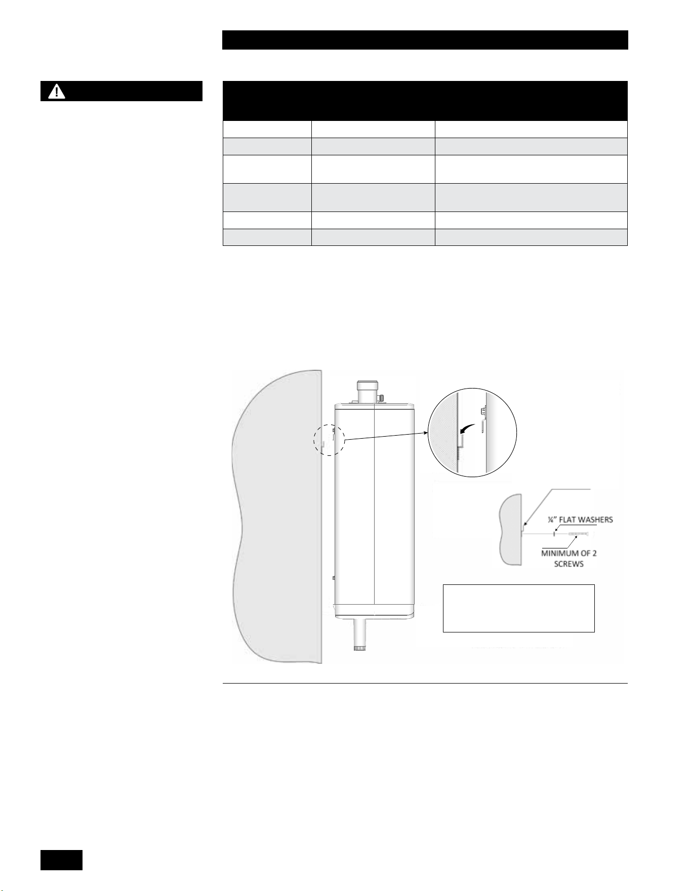
FOR BRACKET USE TWO ¼” X 1¾” LAG
SCREWS WITH FLAT WASHERS INTO
STUDS. FOR METAL MOUNTING SYSTEM
USE ¼” BOLTS WITH FLAT WASHERS.
FOR BRACKET USE TWO ¼” X 1¾” LAG
SCREWS WITH FLAT WASHERS INTO
STUDS. FOR METAL MOUNTING SYSTEM
USE ¼” BOLTS WITH FLAT WASHERS.
UNIT
MOUNT BRACKET TO WALL,
HOOK UNIT OVER TOP.
Figure 2: Wall mounting of unit
1.3.1 Mobile Home Installations
TheTankless Water Heater is approved for installation in a manufactured home
(mobile home). Units installed in a mobile or manufactured home must also
conform to the Manufactured Home Construction and Safety Standard, Title 24
CFR, Part 3280 and/or CAN/CSA Z240 MH Series, Mobile Homes.
WARNING
- Exposed water piping and
associated components
(relief valves, circulators, etc.)
must not be in contact with
combustible materials. Check
local codes for required
clearances and/or provide
adequate insulation.
- DO NOT MOUNT THIS UNIT - DO NOT MOUNT THIS UNIT
TO A HOLLOW SHEET ROCK TO A HOLLOW SHEET ROCK
WALL USING ANCHORS. The WALL USING ANCHORS. The
wall mounting bracket must wall mounting bracket must
be bolted to wall studs or a be bolted to wall studs or a
solid wall structure to support solid wall structure to support
the combined weight of the the combined weight of the
unit which can exceed 150 unit which can exceed 150
lbs. (68kg) once installed.lbs. (68kg) once installed.
- Take precautions to avoid
injury during the installation
of this unit.
1-5
INSTALLATION AND OPERATING INSTRUCTIONS
TANKLESS WATER HEATER 199
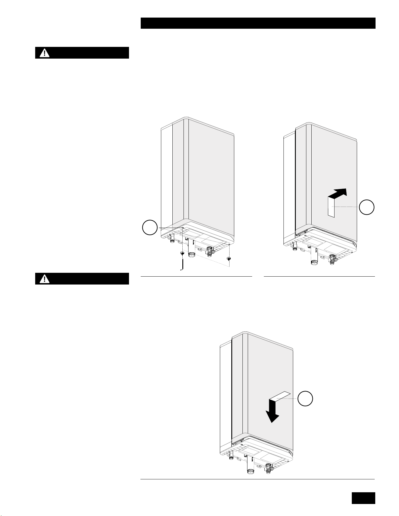
1.3.2 Removing/installing the front panel
•
The front panel of the unit must be removed to perform various maintenance
activities.
•
Loosen both screws (1) under the unit by using a 5 mm allen key. (They are
captive and therefore will not drop out of the lower housing).
•
Slide the front panel (2) upward and then remove it by pulling it towards you.
To replace the front panel, proceed as follows:
• Position the front panel (3) against the unit and slide it downwards until it is
correctly connected to the lower fascia panel.
• Hand tighten screws under the unit using a 5 mm allen key (do not over
tighten)
CAUTION
The front panel has a rubber
seal around the inner edge
sometimes making it very sti
to slide o so please ensure
the unit is secured to the wall
correctly before attempting
this procedure!
WARNING
This is a room sealed cover
and therefor extremely
important that it is tted
correctly, failure to do so can
result in ue gas spillage and
carbon monoxide emissions,
causing severe personal
injury or death.
2
3
1
Figure 3: Loosen screws Figure 4: Frontpanel upward
Figure 5: Positioning the frontpanel
INSTALLATION AND OPERATION INSTRUCTIONS
1-6
TANKLESS WATER HEATER 199
1.4 EXHAUST VENTING AND AIR INTAKE
When you plan the installation, ensure that you consider appropriate venting
materials, travel and termination decisions.
Consider the following when selecting a vent termination location:
• Select a location where the units exhaust will not damage nearby plants,
shrubs,airconditioningequipmentorbeobjectionabletothehomeowner.
• Exhaust gases will form a visible plume during cold weather. Avoid areas
where the plume could obstruct window views.
• Prevailingwindscouldcausewater/icebuilduponnearbyobjectsincluding
building surfaces.
• Avoid locations where people or pets could come in contact with exhaust
gases.
• Avoidlocationssuchasinsidebuildingcorners,nearadjacentbuildingsor
surfaces, window wells, stairwells, alcoves, courtyards, or other recessed
areaswherewindcouldaecttheunit’sperformanceorcauseexhaustgas
recirculation.
• Select a location where the termination is not likely to be damaged by foreign
objectssuchasstonesorballs,orissubjecttobuildupofdebrissuchas
leaves.
Installventinginaccordancewiththerequirementsofthejurisdictionhaving
authority: in Canada, Part 8, Venting Systems of the B149.1-10 Code and any
other local building codes are to be followed. In the USA the National Fuel Gas
Code, ANSI 223.1, latest edition, prevails. Where there is a discrepancy between
theinstallationinstructionsbelow,andthecoderequirements,youmustapplythe
morestringentofthetworequirements.
Provisions for combustion and ventilation air in accordance with the section “Air
for Combustion and Ventilation,” of the National Fuel Gas Code, ANSI Z223.1/
NFPA 54 (latest edition) in the US or Clause 8.2, 8.3 or 8.4 of Natural Gas
and Propane Installation Code, CAN/CSA B149.1 (latest edition) in Canada or
applicable provisions of the local building codes.
Tankless
Water Heater
FLUE GAS
EXHAUST TO
OUTDOORS
Figure 6: Basic exhaust vent assembly
WARNING
- Venting, condensate
drainage, and combustion
air systems for all units
must comply with applicable
codes and the instructions of
their respective Installation
manuals.
- Inspect nished vent and air
piping thoroughly to ensure
all are airtight and comply
with the instructions provided
and with all requirements of
applicable codes.
- Failure to follow all
instructions can result in
ue gas spillage and carbon
monoxide emissions, causing
severe personal injury or
death. Failure to comply will
result in severe personal
injury or death.
DANGER
Failure to properly vent
the unit to the outdoors
as outlined in this Venting
section will result in death
or serious personal injury.
To avoid the risk of re,
explosion, or asphyxiation
from carbon monoxide,
NEVER operate the unit
unless it is properly vented
and has adequate air supply
for proper operation as
outlined in this Venting
section. This unit must have
air supply connected and
terminated to the outdoors.
DANGER
Do not common vent this
tankless water heater with
any other existing or new
appliance, except as outlined
in this units Common Vent
Installation Instructions.

1-7
INSTALLATION AND OPERATING INSTRUCTIONS
TANKLESS WATER HEATER 199
In the Commonwealth of Massachusetts
TheCommonwealthofMassachusettsrequirescompliancewithregulation248
CMR 4.00 and 5.00 for installation of through-the-wall vented gas appliances as
follows:
(a)Forallside-wall,horizontallyvented,gas-fueledequipmentinstalledinevery
dwelling, building, or structure used in whole or part for residential purposes,
including those owned or operated by the Commonwealth and where the side-
wallexhaustventterminationislessthanseven(7)feetabovenishedgrade
in the area of the venting, including but not limited to decks and porches, the
followingrequirementsshallbesatised.
1. INSTALLATION OF CARBON MONOXIDE DETECTORS. At the time of
installationoftheside-wall,horizontallyvented,gas-fueledequipment,the
installingplumberorgasttershallobservethatahard-wiredcarbonmonoxide
detectorwithanalarmandbatterybackupisinstalledontheoorlevelwherethe
gasequipmentistobeinstalled.Inaddition,theinstallingplumberorgastter
shall observe that a battery-operated or hard-wired carbon monoxide detector
with an alarm is installed on each additional level of the dwelling, building, or
structureservedbytheside-wall,horizontallyvented,gas-fueledequipment.
It shall be the responsibility of the property owner to secure the services of
qualiedlicensedprofessionalsfortheinstallationofhard-wiredcarbonmonoxide
detectors.
a.Intheeventthattheside-wall,horizontallyvented,gas-fueledequipmentis
installed in a crawl space or an attic, the hard-wired carbon monoxide detector
withalarmandbatterybackupmaybeinstalledonthenextadjacentoorlevel.
b.Intheeventthattherequirementsofthissubdivisioncannotbemetatthetime
of completion of installation, the owner shall have a period of thirty (30) days to
complywiththeaboverequirements,provided,however,thatduringsaidthirty
(30) day period, a battery-operated carbon monoxide detector with an alarm shall
be installed.
2. APPROVED CARBON MONOXIDE DETECTORS. Each carbon monoxide
detectorasrequiredinaccordancewiththeaboveprovisionsshallcomplywith
NFPA720andbeANSI/UL2034-listedandIAS-certied.
3.SIGNAGE.Ametalorplasticidenticationplateshallbepermanentlymounted
to the exterior of the building at a minimum height of eight (8) feet above grade
directly in line with the exhaust vent terminal for the horizontally vented, gas-
fueledheatingapplianceorequipment.Thesignshallread,inprintsizenoless
than one-half (1/2) inch in size, “GAS VENT DIRECTLY BELOW. KEEP CLEAR
OF ALL OBSTRUCTIONS.”
4. INSPECTION. The state or local gas inspector of the side-wall, horizontally
vented,gas-fueledequipmentshallnotapprovetheinstallationunless,upon
inspection, the inspector observes carbon monoxide detectors and signage
installed in accordance with the provisions of 248 CMR 5.08 (2)(a)(1 through 4).
(b)EXEMPTIONS:Thefollowingequipmentisexemptfrom248CMR5.08(2)(a)
(1 through 4):
1.TheequipmentlistedinChapter10entitled“EquipmentNotRequiredToBe
Vented” in the most current edition of NFPA 54 as adopted by the Board, and
2.Product-approvedside-wall,horizontallyvented,gas-fueledequipment
installed in a room or structure separate from the dwelling, building, or structure
used in whole or in part for residential purposes.
(c) MANUFACTURER REQUIREMENTS – GAS EQUIPMENT VENTING
NOTE
For the State of
Massachusetts, use only
plastic piping, ttings
and vent terminations as
specied in this manual
which are approved by the
Massachusetts Board of State
Examiners of Plumbers and
Gas for venting of appliances
(see hyperlink below):
https://licensing.reg.state.
ma.us/pubLic/pl_products/
pb_pre_form.asp

INSTALLATION AND OPERATION INSTRUCTIONS
1-8
TANKLESS WATER HEATER 199
SYSTEM PROVIDED. When the manufacturer of product-approved side-wall,
horizontallyvented,gas-fueledequipmentprovidesaventingsystemdesignor
ventingsystemcomponentswiththeequipment,theinstructionsprovidedby
themanufacturerforinstallationoftheequipmentandtheventingsystemshall
include:
1. Detailed instructions for the installation of the venting system design or the
ventingsystemcomponents;and
2. A complete parts list for the venting system design or venting system.
(d) MANUFACTURER REQUIREMENTS – GAS EQUIPMENT VENTING
SYSTEM NOT PROVIDED. When the manufacturer of product-approved side-
wall,horizontallyvented,gas-fueledequipmentdoesnotprovidethepartsfor
ventingtheuegases,butidenties“specialventingsystems,”thefollowing
requirementsshallbesatisedbythemanufacturer:
1. The referenced “special venting systems” instructions shall be included with
theapplianceorequipmentinstallationinstructions,and
2. The “special venting systems” shall be product-approved by the Board, and
the instructions for that system shall include a parts list and detailed installation
instructions.
(e) A copy of all installation instructions for all product-approved side-wall,
horizontallyvented,gas-fueledequipment,allventinginstructions,allpartslists
for venting instructions, and/or all venting design instructions shall remain with
theapplianceorequipmentatthecompletionoftheinstallation.

1-9
INSTALLATION AND OPERATING INSTRUCTIONS
TANKLESS WATER HEATER 199
Removal of Existing Unit from Common Venting
When an existing appliance is removed from a common venting system, the
common venting system is likely to be too large for proper venting of the
appliances remaining connected to it.
At the time of removal of an existing appliance, the following steps must be
followed with each appliance remaining connected to the common venting
system placed in operation, while the other appliances remaining connected to
the common venting system are not in operation.
• Seal any unused openings in the common venting system.
• Visually inspect the venting system for proper size and horizontal pitch, and
determine that there is no blockage or restriction, leakage, corrosion and
otherdecienciesthatcouldcauseanunsafecondition.
• Insofar as is practical, close all building doors and windows and all doors
between the space in which the appliances remaining connected to the
common venting system are located and other spaces of the building. Turn
on clothes dryers and any appliance not connected to the common venting
system. Turn on any exhaust fans, such as range hoods and bathroom
exhausts, so they will operate at maximum speed. Do not operate a summer
exhaustfan.Closereplacedampers.
• Place in operation the appliance being inspected. Follow the lighting
instructions.Adjustthethermostat,sothattheapplianceoperates
continuously.
• Test for spillage at the draft hood relief opening after 5 minutes of main
burneroperation.Usetheameofamatchorcandle,orsmokefroma
cigarette, cigar, or pipe.
• After it has been determined that each appliance remaining connected to
the common venting system properly vents when tested as outlined above,
returndoors,windows,exhaustfans,replacedampersandanyothergas-
burning appliance to their previous conditions of use.
• Any improper operation of the common venting system must be corrected
so the installation conforms with the National Fuel Gas Code, ANSI Z223.1/
NFPA 54, (latest edition) in the US or the Natural Gas and Propane
Installation Code, CSA B149.1 (latest edition) in Canada. When resizing any
portion of the common venting system, the common venting system must be
resized to approach the minimum size as determined using the appropriate
tables in the National Fuel Gas Code, ANSI Z223.1/NFPA 54, (latest edition)
in the US or the Natural Gas and Propane Installation Code, CSA B149.1
(latest edition) in Canada.
NOTE
The ue gas temperature
sensor reports the current
ue gas exhaust temperature
to the unit’s controller. If
necessary, the controller
will reduce the input of the
tankless water heater to
meet the ue gas exhaust
temperature requirements of
PVC material. The controller
locks out the unit if this
temperature is exceeded, and
displays F003.
CAUTION
- The minimum wall thickness
for venting is 1" and the
maximum wall thickness for
venting is 14".
- Do not connect this tankless
water heater to a chimney ue
serving a separate appliance
designed to burn solid fuel.
- The air intake tting can be
moved to the left or to the
right of the exhaust tting.
INSTALLATION AND OPERATION INSTRUCTIONS
1-10
TANKLESS WATER HEATER 199
1.4.1 Applications
All Tankless Water Heaters must be installed as a Direct Vent venting system.
The combustion air must be piped in from the outdoors and connected directly
totheunit’scombustionairconnection.See section 1.4.7 for air intake piping
requirements.
1.4.2 Exhaust Vent Material
Use of ABS, cellular core PVC (ASTM F891), cellular core CPVC, or Radel®
(polyphenolsulfone) in venting systems is prohibited.
Exhaust Vent Material – CANADA
Use only PVC, CPVC, Polypropylene (PPS), or stainless steel* vent components.
Venting components must be approved for use with a Category IV appliance,
listed under ULC S636 and must comply with CSA B149.1 (latest edition).
• PVC (ULC-S636)
• CPVC (ULC-S636)
• Polypropylene (ULC-S636)
• Stainless steel* (ULC-S636)
Exhaust Vent Material – USA
Use only PVC, CPVC, Polypropylene (PPS), or stainless steel* vent components.
Ventingcomponentsmustbeapprovedbytheauthorityhavingjurisdictionandas
follows:
• PVC (Schedule 40 ASTM D1785)
• CPVC (Schedule 40 ASTM F441)
• Polypropylene (UL1738 / ULC-S636)
• Stainless Steel* (Type BH), DuraVent FasNSeal, HeatFab Saf-T Vent, Z-Flex
Z-Vent
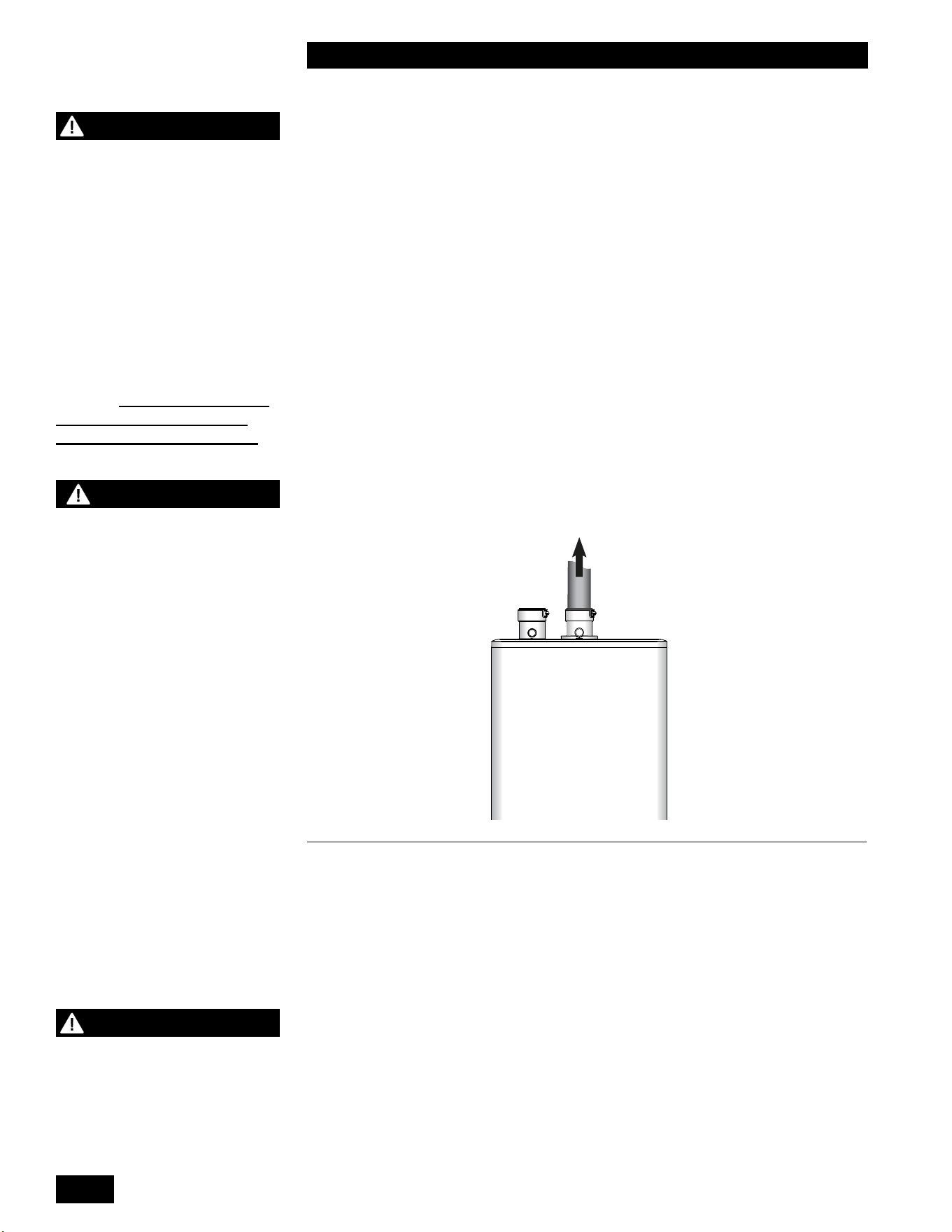
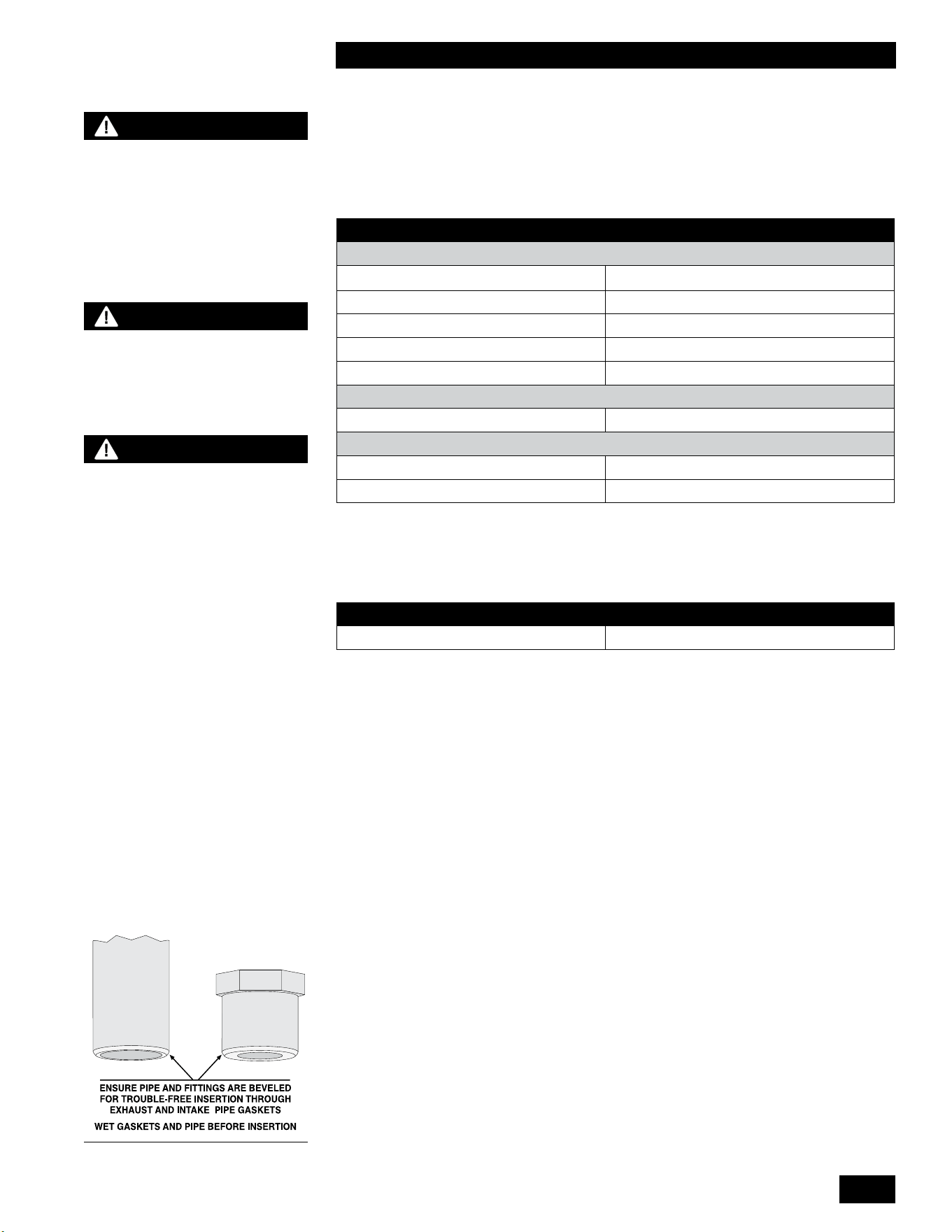
Thisunitisequippedwithatopmounted2”ventconnection.Wetthevent
connection gasket and pipe with clean water prior to assembly. Insert 2” PVC or
CPVC directly into the units vent connection and secure the pipe by tightening
the clamp.
Polypropyleneventingwillrequireanadapterfromtheventingmanufacturer
to transition from the 2” vent connection to the venting system. Centrotherm
InnoFluepolypropyleneventingrequiresadapterpartnumberISAAL0202.Wet
the vent connection gasket and adapter with clean water prior to assembly.
Insert the polypropylene adapter into the units vent connection and secure by
tightening the clamp.
*Manufacturers of stainless steel Type BH venting systems must submit
their approved transition tting to us for evaluation and written approval.
1.4.3 Vent Travel
The maximum exhaust venting length is dependent upon the vent pipe size (2”
or 3”) and the venting material (PVC, CPVC, PPs). See Table 3 for maximum
exhaustventinglengthsandtherequiredventinglengthreductionforeachtting
in the venting system.
Example: When using 6 x 90º CPVC elbows, the maximum lineal measure of
pipeallowedusing3”pipeis72feet(120’–(6x8’=48’)=72’).
WARNING
- Do not mix venting materials
from dierent venting
manufacturers.
These venting materials are
designed to be installed as
part of a complete system.
Failure to comply may result
in severe personal injury or
death.
- Fully insert the approved
venting material into the
unit’s exhaust outlet and
tighten clamp to ensure the
venting connection is locked
in place.
Figure 7: Inlet and outlet vent
connections. Note the ue
exhaust test port.
NOTE
For the State of
Massachusetts, use only
plastic piping, ttings
and vent terminations as
specied in this manual
which are approved by the
Massachusetts Board of State
Examiners of Plumbers and
Gas for venting of appliances
(see hyperlink below):
https://licensing.reg.state.
ma.us/pubLic/pl_products/
pb_pre_form.asp
1-11
INSTALLATION AND OPERATING INSTRUCTIONS
TANKLESS WATER HEATER 199
For 3" Flexible PPs, up to 35 actual lineal feet are allowed in a nominally vertical
orientation(>45°).Theequivalentlengthof3"FlexiblePPsiscalculatedusing
amultipleof1.4:1,e.g.35'x1.4=49'equivalent.Thebalanceoftheventing
allowance is still available for use with rigid PPs piping material.
2" Flexible PPs is not allowed.
EXHAUST PIPE SIZE/FITTINGS MAXIMUM EQUIVALENT LENGTH
Schedule 40 PVC, CPVC or PPs – Allowances are for each side separately.
2"
65'65'*
3" 120'
2" or 3" 90° Long Sweep Vent Elbow Allow5equivalentfeet
2" or 3" 90° Short Sweep Vent Elbow Allow8equivalentfeet
2" or 3" 45° Vent Elbow Allow3equivalentfeet
PPS
PPs 87-90° Elbow Allow8equivalentfeet
Flex PPS
2" PPs Flex Not Allowed
3" PPs Flex 35'Actual(Equivalent=Actualx1.4)
Table 3: Maximum Exhaust Venting Length
* The input rate will derate as vent length increases. See table below for
approximate derate at 2" maximum vent length.
MAXIMUM FIRING RATE APPROXIMATE DERATE
199,000
10 - 16%10 - 16%
Follow all installation instructions supplied by the pipe and tting
manufacturer. Prior to assembly, ensure all venting components are clean of
burrs/debris which could clog the fan, burner, and heat exchanger.
General Venting/Piping Requirements
Iftheventlengthrequiresincreasingtheventpipesizeto3",thetransitionfrom
the2"ventconnectorto3"ventingmustoccurwithintherst18"ofthetopofthe
unit and must be done in a vertical section to avoid pooling of condensate. Slope
exhaust venting back towards the unit with a pitch of at least 1/4" per foot. Follow
ventingmanufacturerpitchrequirements,socondensaterunsbacktowardsthe
trap. Support air intake and vent piping per local code and vent manufacturers
requirements.Intheabsenceofsupportrequirements,supporttheairintakeand
vent piping at every vertical and horizontal transition as well as every 5' of run.
Begin the vent system installation at the unit and work towards the outdoor
termination. We recommend using a bird screen of 1/4" stainless steel or plastic
mesh (e.g., IPEX System 636 drain grate for CPVC systems) to guard against
foreignobjects.
BEST PRACTICES
To reduce the possibility of
expansion noise, allow a 1/4"
gap around the exhaust and
air intake piping.
NOTE
The bird screen is optional
for exhaust piping in cold
weather climates.
WARNING
C
ombustion air must not be
drawn from areas containing
corrosive air from swimming
pools or spas, including air
directly next to outdoor pools
and spas.
Figure 8
INSTALLATION AND OPERATION INSTRUCTIONS
1-12
TANKLESS WATER HEATER 199
Securejointsusingappropriatesolventcementtobondtherespectivepipe
material (Canada: PVC/CPVC cement approved under ULC-S636, in accordance
with its manufacturer instructions; USA: PVC (ASTM D2564), or CPVC (ASTM
F493).UsetransitioncementanywherethatPVCandCPVCarejoined.Follow
thecementmanufacturer’sinstructionscloselywhenjoiningvariouscomponents.
For PPs, connections must be secured using approved retainer clips supplied by
the respective PPs manufacturer.
Ensurethatallventconnectionsareliquidandpressuretight.Priortoringthe
unit, and before any of the venting run is concealed by the building construction,
youmusttesttheexhaustjoints,usingasoap/watersolution.Youmustllthe
condensate trap before testing.
1.4.4 Venting Passage Through Ceiling and Floor
• Conrmmaterialmeetslocalcodesincludingrestoppingrequirements.
Somelocaljurisdictionsrequirethataminimuminitiallengthofpipebe
exposed or accessible for inspection.
•
Pipe clearances best practice allows a minimum 1/4" gap around the pipe to
prevent binding and expansion noise. Follow local codes.
• Allpipingmustbeliquidandpressuretight.
1.4.5 Rooftop Vent Termination
Direct Vent - Two Pipe
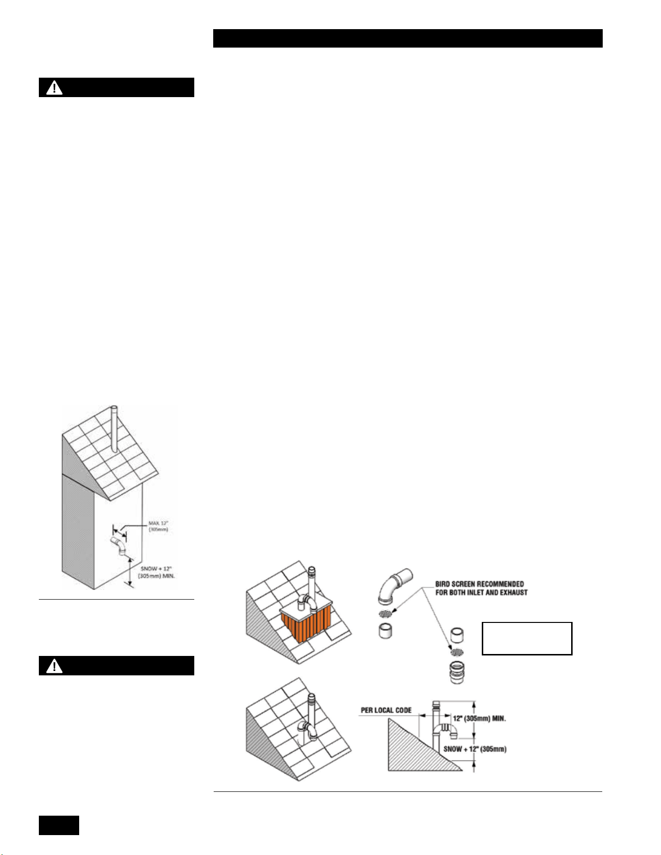
Rooftop vents must terminate as follows:
•
The exhaust pipe can terminate in an open vertical orientation without concern
aboutraininltration;rainwilldrainawaythroughthecondensatetrap.
•
The intake air pipe is not typically drained, so it must be terminated with a down-
turned elbow (see Figure 10). The intake pipe does not need to penetrate the
roofatthesameelevationastheexhaust(asshown);lowerdowntheroofis
OK.
• The air intake pipe may terminate on the side wall of the building as long as
the air intake terminal is turned down and the side wall of the building is not
exposed to large wind loads i.e.: prevailing winds. (see Figure 9)
WARNING
Condensate can cause
corrosion of metal roong
components and other
roong materials. Check
with the builder or roong
contractor to ensure that
materials are resistant to
acidic condensate. pH levels
can be as low as 3.0
[18" (457 mm) Canada] MIN.
NOTE: THE BIRD SCREEN
IS OPTIONAL IN COLD
WEATHER CLIMATES
CAUTION
Vent termination clearances
in this section are code
minimum, or recommended
minimum requirements,
and may be inadequate for
your installation. You must
examine building envelope
details, and take measures to
avoid admission of moisture
into building structures.
Serious structural damage
may occur if adequate
precautions and clearances
are not allowed for.
These precautions are to be
observed for neighboring
structures as well as for
the structure the unit(s) are
installed in.
Figure 10: Rooftop vent terminal congurations
Figure 9: Rooftop vent terminal
congurations
1-13
INSTALLATION AND OPERATING INSTRUCTIONS
TANKLESS WATER HEATER 199
• Optionalbirdscreenmaybeplacedinaterminationtting.Leaveunglued,
and hold in place with a short nipple to allow easy access for cleaning.
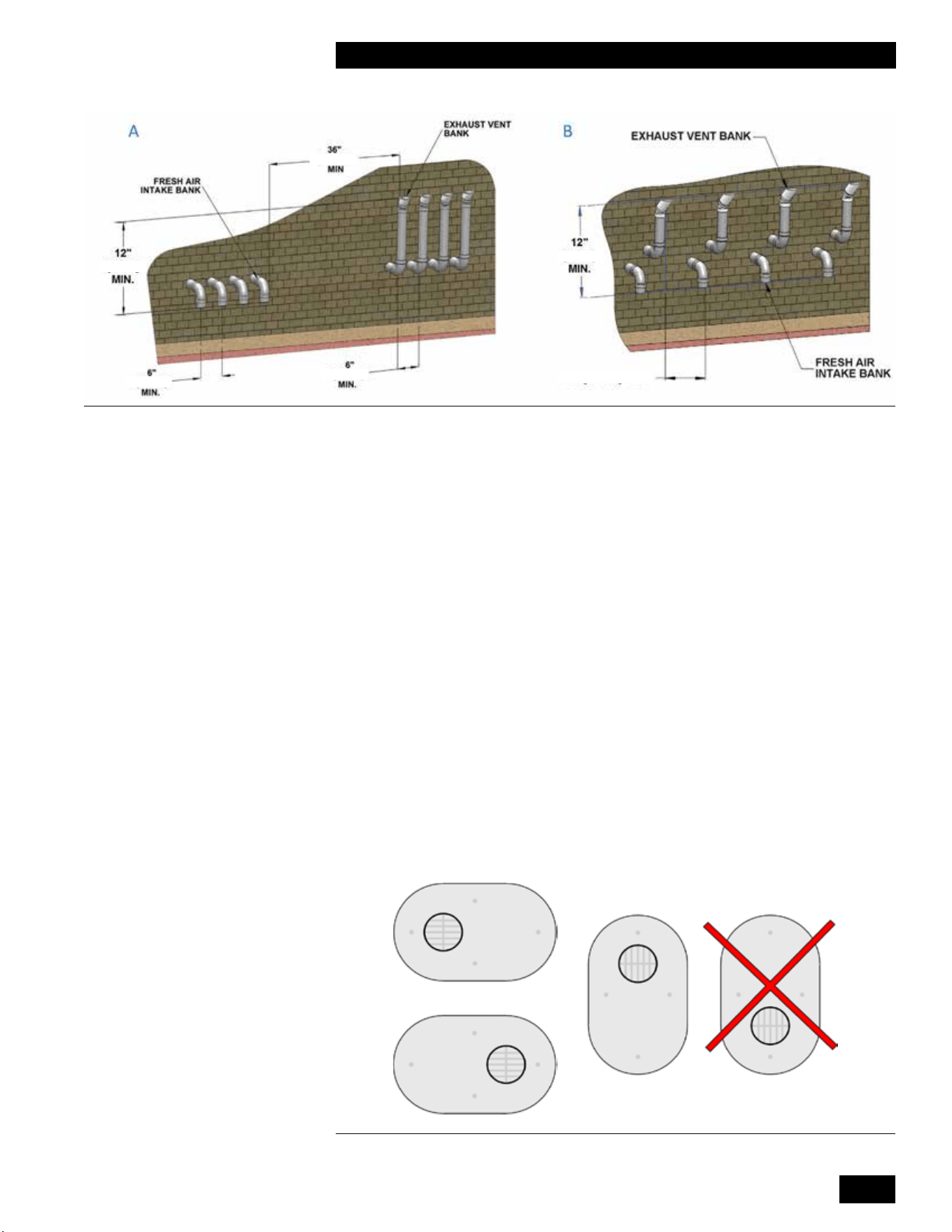
• For roof top venting of multiple unit sets, group all intake terminals together
for a common penetration through a custom cap. Alternatively, place in
theclosestproximityachievableusingcommonlyavailablepipeashing.
Similarly, group the exhaust pipes and place the 2 separate groups of pipes
at least 3' apart (the closest intake and exhaust pipes must be 36" - or more -
apart). Use the same 12" (minimum) vertical separation for 2 pipe option.
• DO NOT exhaust vent into a common venting system, except as outlined
in this units Common Vent Installation Instructions.
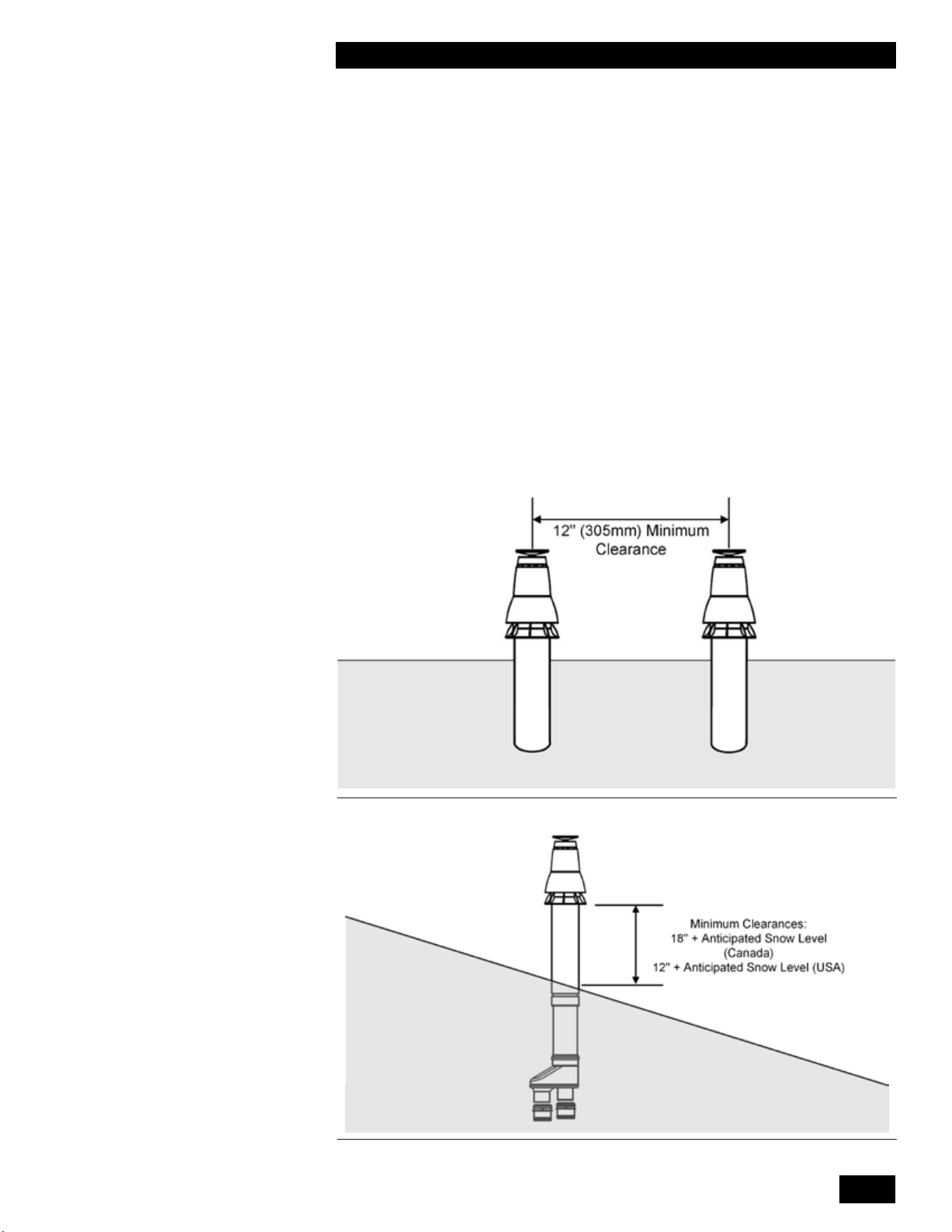
DIRECT VENT CONCENTRIC ROOF TOP TERMINATION
Roof Top Concentric Termination kits are approved for use with this unit.
For vertical roof top concentric terminations, you must follow the installation
instructions supplied by the manufacturer. Care must be taken to install the
termination kit a minimum horizontal distance of 10' (305cm) away from any
portion of the building and a minimum of 12" (305 mm) [18" (457 mm) Canada]
above the roof line plus the anticipated snow line (see Figures 11 and 12).
Figure 11: Vertical Concentric Termination - Two Kits
Figure 12: Vertical Concentric Termination - Single Kit
INSTALLATION AND OPERATION INSTRUCTIONS
1-14
TANKLESS WATER HEATER 199
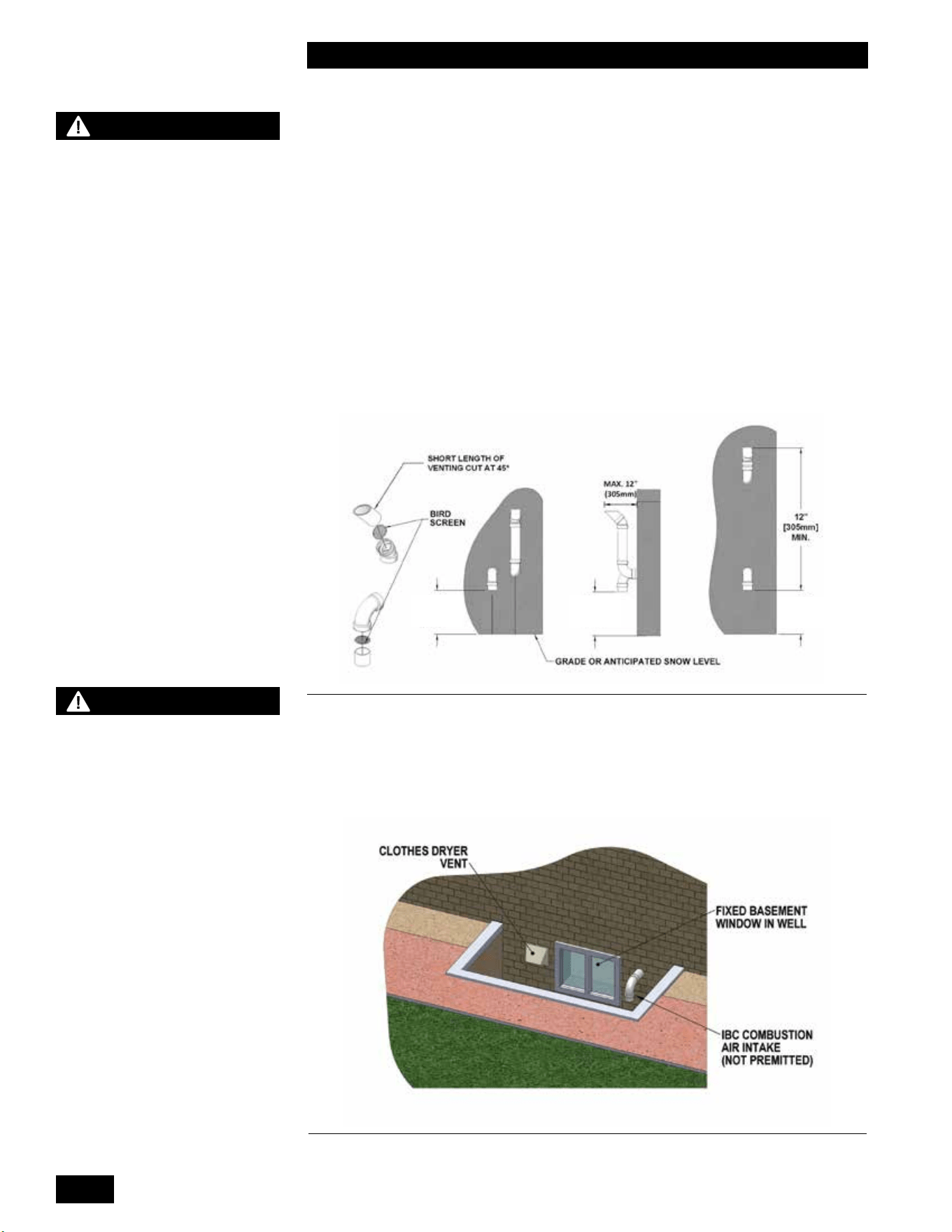
1.4.6 Sidewall Vent Termination
Direct Vent - Two Pipe
Sidewall direct vent applications must be vented as follows:
• Both the inlet and exhaust terminations must bemust be located on the same plane
(side) of the building.
• The exhaust outlet is to be placed so as to reach 12" minimum above the
down-turned intake - to avoid intake re-ingestion of exhaust gases.
• The elevation of both pipes can be raised in “periscope style” after passing
throughthewall,thenconguredasinFigure 13,togainrequiredclearance.
• Usea45°elbowontheexhaustterminationtolaunchtheplumeupando
the sidewall, for protection of wall.
• Optionalbirdscreenmaybeplacedinaterminationtting.Leaveunglued,
and hold in place with a short nipple to allow easy access for cleaning.
SNOW + 12"
[305mm]
MIN.
SNOW + 12"
[305mm]
MIN.
SNOW + 12"
[305mm]
MIN.
WARNING
- You must maintain at least
the minimum separation of
exhaust vent termination from
unit’s intake air as illustrated
in gures 9, 10 and 13 and
15. Failure to do so can result
in a dangerous situation
where exhaust gases are
pulled in with combustion air.
Damage to the unit can result
from a failure to maintain
these separations. Improper
installation will void the
warranty.
- You must not cover non-
metallic vent pipe and ttings
with thermal insulation.
- In areas of high snowfall,
users must be advised to
check side wall vent and
air intake terminations on
a regular basis to ensure
blockage does not occur.
WARNING
The vent for this appliance
must not terminate:
1. Over public walkways in
the US. In Canada 7’ above
public walkways.
2. Near sot vents or crawl
space vents or other areas
where condensate or vapor
could create a nuisance or
hazard or cause property
damage.
3. Wherever condensate
vapor could cause damage
or could be detrimental to the
operation of regulators, relief
valves, or to other equipment..
Figure 13: Sidewall vent termination - piping conguration
Figure 14Figure 14: Prohibited installation
1-15
INSTALLATION AND OPERATING INSTRUCTIONS
TANKLESS WATER HEATER 199
For sidewall venting of multiple units, group all intake terminals together with 6"
(minimum) lateral spacing, and similarly group the exhaust pipes. Place the 2
groups on the same plane of the building (e.g., north facing wall). Place the 2
groups of pipes at least 3' apart (the closest intake and exhaust pipes must be
36" - or more – apart). Use same 12" (minimum) vertical separation (see A in
Figure 15). Alternatively, as long as the units are identical models - intake and
exhaust terminals can maintain a minimum of 12" of separation horizontally from
anyexhaustorinletterminationofanadjacentunit (see B in Figure 15).
DIRECT VENT SIDE WALL TERMINATION KITS
The sidewall Termination kits approved for use with the tankless water heater are
subjecttorestrictions.NOTE:Somejurisdictionsmaynotallowthistypeofside
wall termination due to close proximity to the neighboring properties. See Figures
16, 17 and 18 on page 1-15, 1-16
You must follow the installation instructions, clearances and wall thickness
requirementsoftheapprovedventterminationmanufacturer.
Approved Side Wall Termination Kits are listed below:
• 2"PVClowproleterminationkit-Part#P-741
• 3"PVClowproleterminationkit-Part#P-742
Vent on Left or Right Side
Figure 15: Sidewall vent termination - multiple vent piping conguration
[305mm]
[305mm]
[152mm]
[152mm]
12" [305mm] MIN.
[915mm]
Figure 16 PVC low prole termination acceptable orientations
INSTALLATION AND OPERATION INSTRUCTIONS
1-16
TANKLESS WATER HEATER 199
Concentric Side Wall Termination Kits
Concentric Sidewall Termination kits approved for use with the tankless water
heateraresubjecttorestrictions.NOTE:Somejurisdictionsmaynotallowthis
type of sidewall termination due to close proximity to the neighboring properties.
You must follow the installation instructions, clearances, and wall thickness
requirementsoftheapprovedventterminationmanufacturer.
Approved Concentric Sidewall Termination kits are:
• 3" PVC (UL 1738) – Ipex #397006
• 3" PVC (ULC-S636) – Ipex #196006
• 3" CPVC (ULC-S636) – Ipex #197009
• 2"CentrothermInnouePPs-#ICWT242(Termination)
#ICTCR24 (2 Pipe Adapter)
• 3"CentrothermInnouePPs-#ICWT352(Termination)
#ICCT3503 (2 Pipe Adapter)
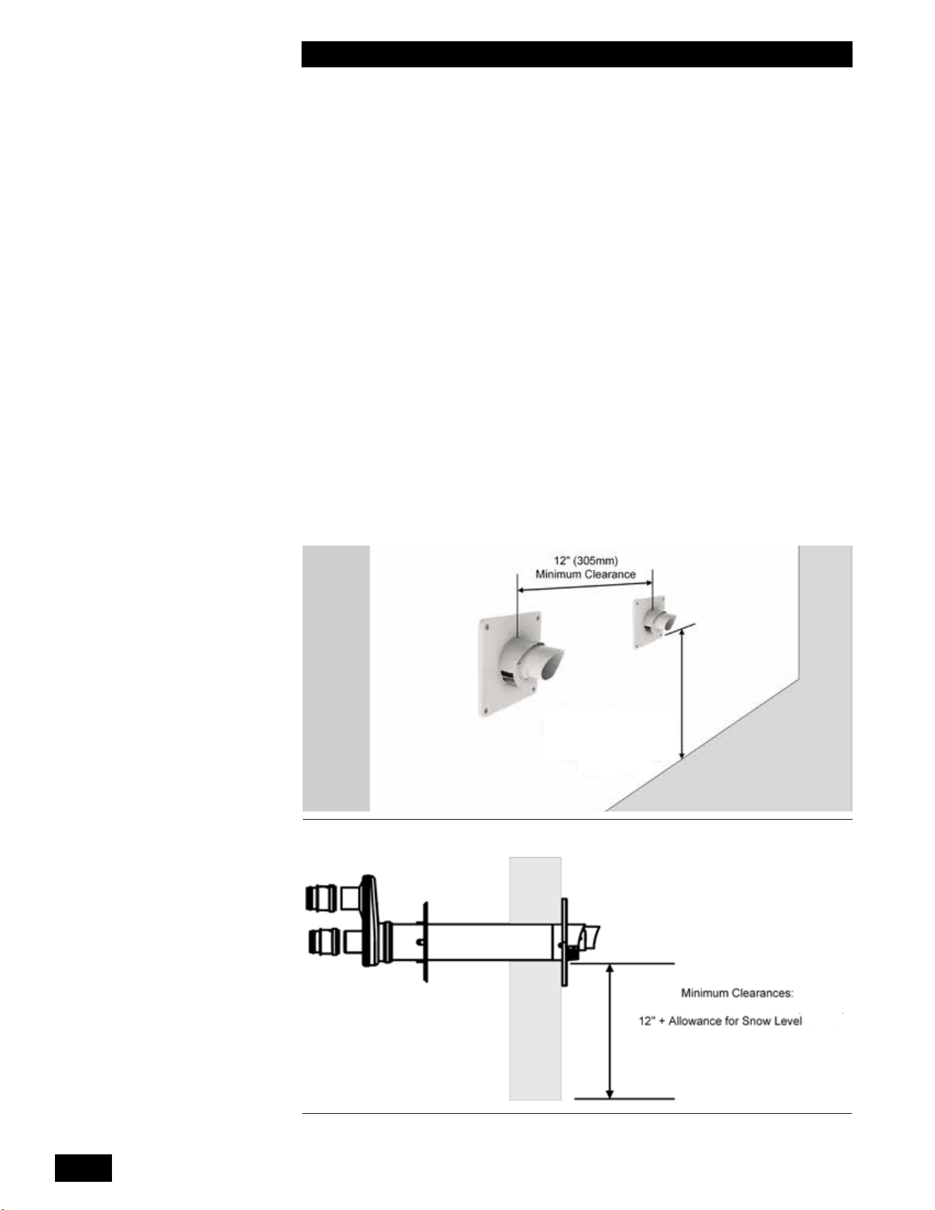
Installation of multiple Concentric Side Wall Termination kits must be:
• On the same horizontal line (not stacked)
• With a minimum horizontal separation of 12" center to center
12" + Allowance
for Snow Level
Figure 17: Horizontal Polypropylene Concentric Termination - Two Kits
Figure 18: Horizontal Polypropylene Concentric Termination - Single Kit
1-17
INSTALLATION AND OPERATING INSTRUCTIONS
TANKLESS WATER HEATER 199
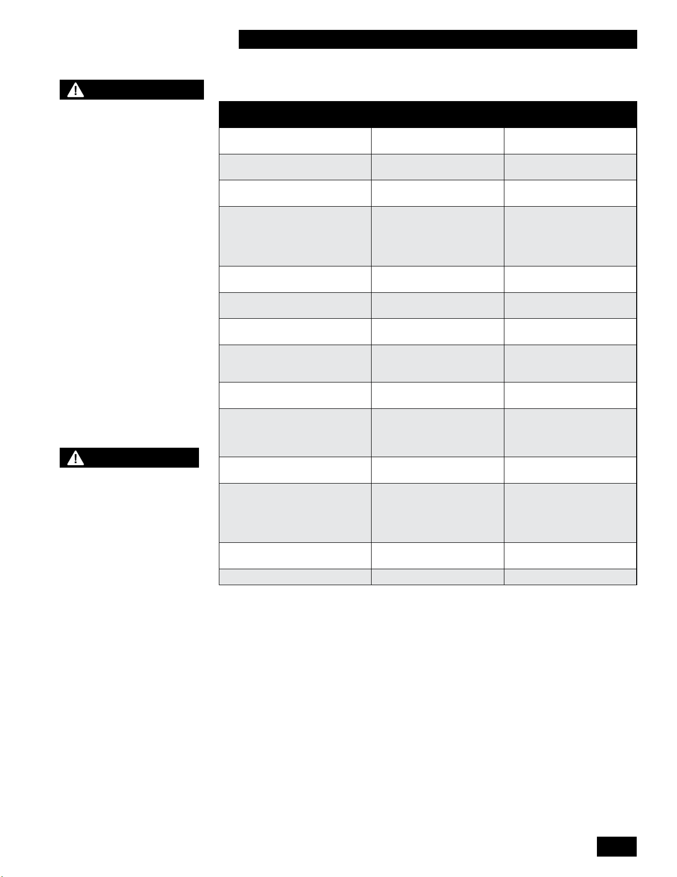
Vent terminal clearance minimums are as follows:
CANADIAN
INSTALLATIONS
1, 3
US
INSTALLATIONS
2, 3
A=Clearanceabovegrade,
veranda, porch, deck, or balcony
12 in (30 cm) 12 in (30 cm)
B=Clearancetowindowordoor
that may be opened
36 in (91 cm) for appliances
over 100,000 Btuh (30kW)
12 in (30 cm)
C=Clearancetopermanently
closed window
* (Recommend minimum 1
ft (30 cm))
* (Recommend minimum 1
ft (30 cm))
D=Verticalclearanceto
ventilatedsotlocatedabove
the terminal within a horizontal
distance of 2 ft (61 cm) from the
center line of the terminal.
* (Recommend minimum 2
ft (61 cm))
* (Recommend minimum 2
ft (61 cm))
E=Clearancetounventilated
sot
*(Recommend minimum 1 ft
(30 cm))
* (Recommend minimum 1
ft (30 cm))
F=Clearancetooutsidecorner * (Recommend minimum 4
ft (122 cm))
* (Recommend minimum 4
ft (122 cm))
G=Clearancetoinsidecorner * (Recommend minimum 4
ft (122 cm))
* (Recommend minimum 4
ft (122 cm))
H=Clearancetoeachsideof
center line extended above
meter/regulator assembly
3 ft (91 cm) within a height
of 15 ft (4.6m)
*
I=Clearancetoserviceregulator
vent outlet
3 ft (91 cm) *
J=Clearancetononmechanical
air supply inlet to building or the
combustion air inlet to any other
appliance
36 in (91 cm) for appliances
over 100,000 Btuh (30 kW)
12 in (30cm)
K=Clearancetoamechanical
air supply inlet
6 ft (1.83 m) 3 ft (91 cm) above if within
10 ft (3 m) horizontally
L=Clearanceabovepaved
sidewalk or paved driveway
located on public property
7 ft (2.13 m) † Vents cannot be located
above public walkways
or other areas where
condensate or vapor can
cause a nuisance or hazard.
M=Clearanceunderveranda,
porch deck, or balcony
12 in (30 cm) ‡ *
Clearancetoadjacentwall 6 ft (1.83 m) 6 ft (1.83 m)
1 In accordance with the current CSA B149.1 Natural Gas and Propane Installation Code
2 In accordance with the current ANSI Z223.1 / NFPA 54 National Fuel Gas Code
3Iflocallyadoptedinstallationcodesspecifyclearancesdierentthanthoseillustrated,thenthemoststringentshall
apply.
† A vent shall not terminate directly above a sidewalk or paved driveway that is located between two single family
dwellings and serves both dwellings.
‡ Permittedonlyifveranda,porch,deck,orbalconyisfullyopenonaminimumoftwosidesbeneaththeoor.
* Clearanceinaccordancewithlocalinstallationcodesandtherequirementsofthegassupplier.Theminimumdistance
fromadjacentpublicwalkways,adjacentbuildings,openablewindows,andbuildingopeningsshallnotbelessthan
thosevaluesspeciedintheNationalFuelGasCode,ANSIZ223.1/NFPA54,and/ortheNaturalGasandPropane
Installation Code, CSA B149.1
WARNING
- In addition to preventing
ingestion of chemical
contaminants, care must
be taken to ensure air
intake terminals are not
installed in locations
where contamination might
occur due to ingestion of
particulate foreign material
(dust, dirt and debris).
- Intake air openings must
be congured such that
rain or other forms of
moisture cannot enter the
air intake piping system.
Otherwise serious damage
to the unit may result.
NOTE
Care must be taken when
installing air intake piping
to ensure that a “trap” is
not formed in the piping
so as to allow a build-up
of water, and blockage of
intake air.
Such blockage will result
in a unit’s safety shut-
down.
INSTALLATION AND OPERATION INSTRUCTIONS
1-18
TANKLESS WATER HEATER 199
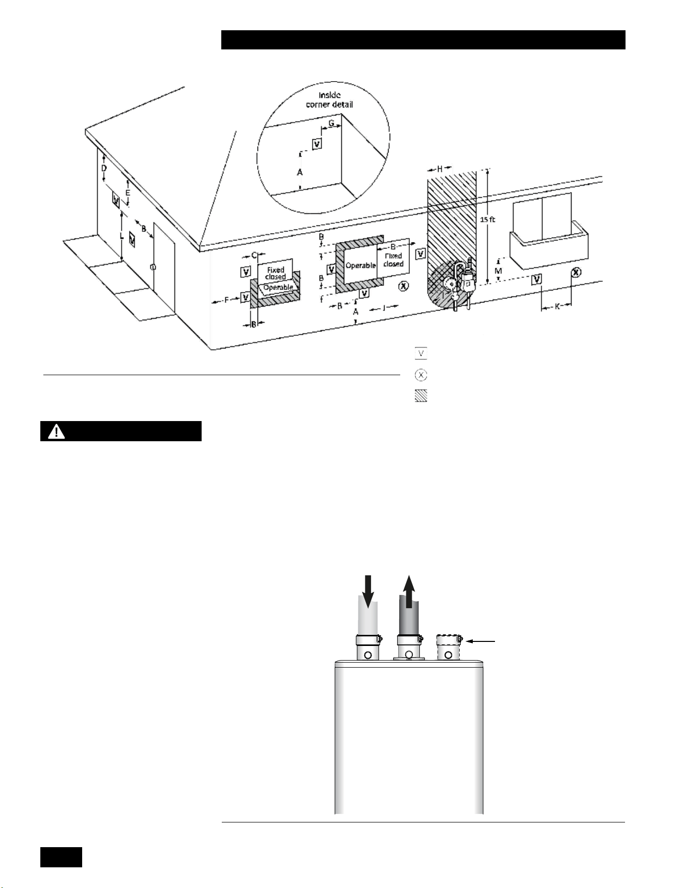
1.4.7 “Direct Vent” Combustion Air Intake Piping
The unit must always be installed as a Direct Vent venting system with the
combustionairpipeddirectlyfromtheoutdoorstotheunit’scombustionair
connection. Provisions for combustion and ventilation air are in accordance with
the section “Air for Combustion and Ventilation”, of the National Fuel Gas Code,
ANSI Z223.1/NFPA 54 (latest edition) in the US or Clause 8.2, 8.3 or 8.4 of
Natural Gas and Propane Installation Code, CAN/CSA B149.1 (latest edition) in
Canada, or applicable provisions of the local building codes.
Tankless
Water Heater
FLUE GAS
EXHAUST TO
OUTDOORS
COMBUSTION
AIR FROM
OUTDOORS
ALTERNATIVE
COMBUSTION AIR
CONNECTION
“DIRECT VENT”
INSTALLATION
CHECK AIR INTAKE
OUTSIDE TO MAKE SURE
IT IS CLEAR OF
OBSTRUCTIONS
FLUE GAS
EXHAUST TO
OUTDOORS
COMBUSTION
AIR FROM
OUTDOORS
ALTERNATIVE
COMBUSTION AIR
CONNECTION
Figure 19: Vent Terminal Clearance
Vent terminal
Air supply inlets
Area where terminal is not permitted
NOTE
Combustion air connection
may be moved from one side
to the other:
- Remove the retaining clip
screws then lift tab at back of
plug and rotate 1/8th of a turn
counter-clockwise to remove
from top of cabinet.
- Remove the retaining clip by
removing both screws then
lift tab at back of combustion
air connection and rotate
1/8th of a turn counter-
clockwise to remove from top
of cabinet.
- Reinstall plug and
combustion air connection
in the desired locations then
rotate 1/8
th
of a turn clockwise
until tab latches into the top
of the cabinet.
- Reinstall the retaining clip
over the combustion air
connection tab and secure
with two screws. Reinstall
two screws in the top of the
cabinet near the plug.
Figure 20: Direct vent combustion air intake
1-19
INSTALLATION AND OPERATING INSTRUCTIONS
TANKLESS WATER HEATER 199
Intake Pipe Sizing
For 3" Flexible PPs, you can use up to 35 actual linear feet in a nominally vertical
orientation(>45°).Theequivalentlengthof3"FlexiblePPsmustbecalculated
usingamultipleof1.4:1,e.g.35'x1.4=49'equivalent.Thebalanceofthe
venting allowance is still available for use with rigid PPs piping material.
2" Flexible PPs is not allowed.
INTAKE PIPE SIZE/FITTINGS MAXIMUM EQUIVALENT LENGTH
Schedule 40 PVC, ABS, CPVC or PPs – Allowances are for each side separately.
2" 65'*
3" 120'
2" or 3" 90° Long Sweep Vent Elbow Allow5equivalentfeet
2" or 3" 90° Short Sweep Vent Elbow Allow8equivalentfeet
2" or 3" 45° Vent Elbow Allow3equivalentfeet
PPS
PPs 87-90° Elbow Allow8equivalentfeet
Flex PPS
3" PPs Flex 35'Actual(Equivalent=Actualx1.4)
Table 4: Maximum intake piping length.
* The input rate will derate as intake length increases. See table below for
approximate derate at 2" maximum intake length.
MAXIMUM FIRING RATE APPROXIMATE DERATE
199,000 10 - 16%
For inlet air, you can use Schedule 40 PVC, CPVC, ABS or PPs piping of any
type. Use the same diameter as vent piping.
Insertcombustionairpipingdirectlyintothe2"femaleplasticttingonthetopof
the unit, and run it horizontally or vertically to the outdoors. We recommend using
a bird screen of 1/4" stainless steel or plastic mesh (eg. IPEX System 636 drain
grateforCPVCsystems)toguardagainstforeignobjects.
Caremustbetakentoensureadequateseparationismaintainedbetweentheair
intakeinletandtheventtermination.Refertotheventterminationconguration
drawings in the “Vent Termination” section above.
Support air intake and vent piping per local code and vent manufacturers
requirements.Intheabsenceofsupportrequirements,supporttheairintakeand
ventpipingateveryverticalandhorizontaltransitionaswellasevery5’ofrun.
1.4.8 “Indoor Air” Combustion Air Intake
The use of indoor air for combustion is prohibited. Combustion air must be
pipedinfromtheoutdoorsandconnecteddirectlytotheunit’scombustionair
connection
1.4.9 Closet Installations
Forinstallationsinaconnedspace(suchasacloset),ventilationopeningsmay
be needed through a door or wall to prevent build-up of excessive heat from
inside the space.
The unit must not be exposed to surrounding conditions above 122°F (50°C) or
below 32°F (0°C).
INSTALLATION AND OPERATION INSTRUCTIONS
1-20
TANKLESS WATER HEATER 199
1.5 CONDENSATE REMOVAL
Thespeciedventcongurationpromotesthesafedrainageofmoisturefromthe
unitandexhaustventingwithoutowingliquidsbackthroughtheheatexchanger.
Reliablesystemoperationrequires(1)properdesignandinstallationofexhaust
ventingtoallowcondensatetorunbacktothedrain/trap;(2)acidneutralization
as appropriate. To achieve these:
1. Allow for a minimum 1/4" per foot slope back to the vent connection, with
appropriate hangers to maintain that gradient (check with the venting
manufacturerastheirsloperequirementmaybestricter).
2. Ensurethesuppliedtrapiscorrectlyinstalledandlledwithwater.
3. Whenrequired,add(andmaintainingoodcondition)apHneutralization
tank.
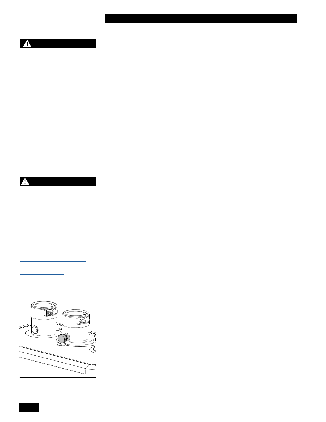
1.5.1 Condensate Trap
The condensate trap must be installed on the bottom of the condensate trap at
the base of the unit.
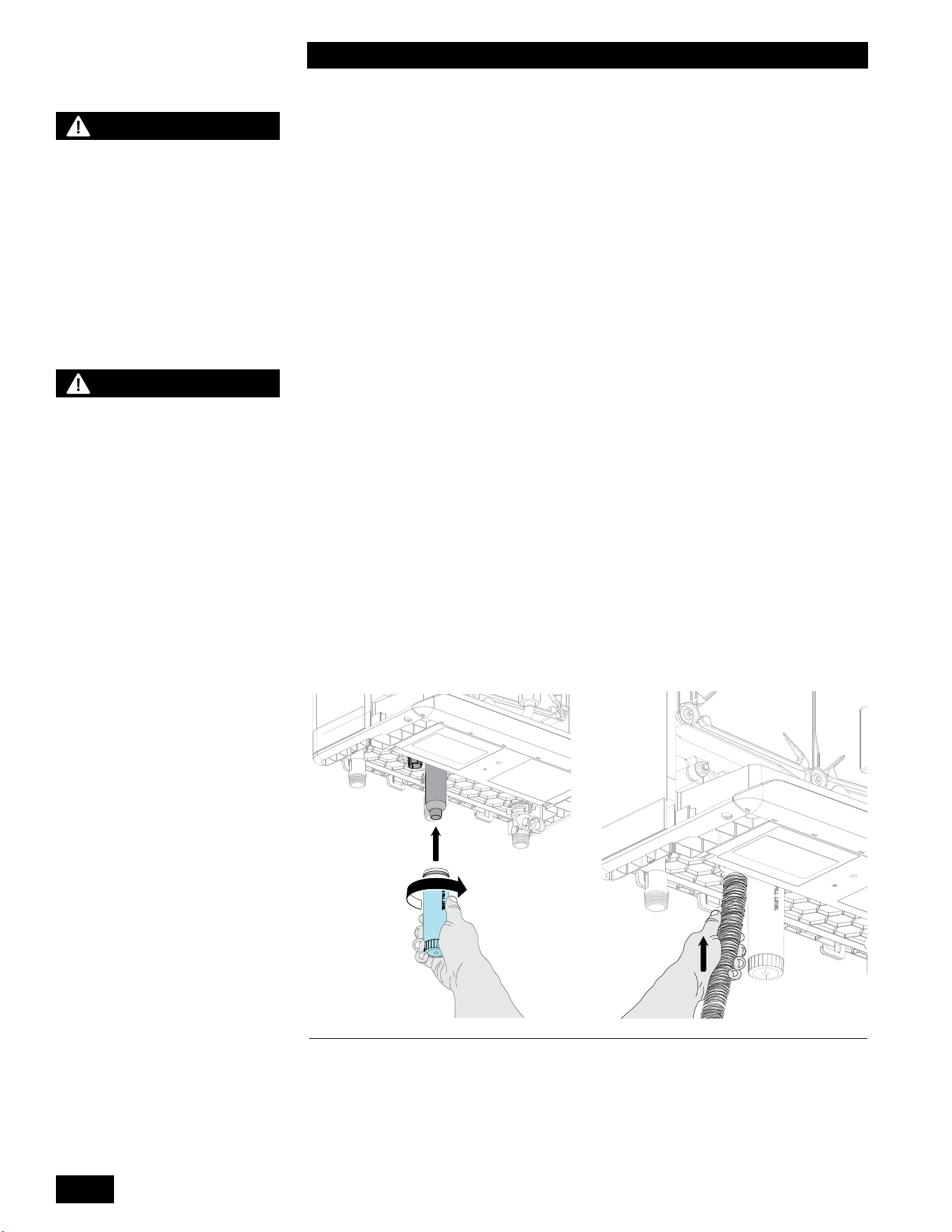
1.5.2 Installing the Condensate Trap
1. Fill the condensate trap cup with water.
2. Install the condensate trap cup on the condensate trap base and twist toward
the right.
3. Attach the drain hose to the condensate trap outlet located to the left of the
condensate trap cup.
Figure 21: Condensate trap installation
WARNING
Fill the trap with water before
initial startup of the unit to
prevent exhaust fumes from
entering the room. Never
operate the water heater
unless the trap is lled with
water.
Failure to comply will result
in severe personal injury or
death.
NOTE
It is the responsibility of
the installing and/or service
Contractor to advise and
instruct the end user on how
to perform the Trap cleaning
procedure, and to advise
that the trap be checked at
least every two months and
cleaned as required.
1-21
INSTALLATION AND OPERATING INSTRUCTIONS
TANKLESS WATER HEATER 199
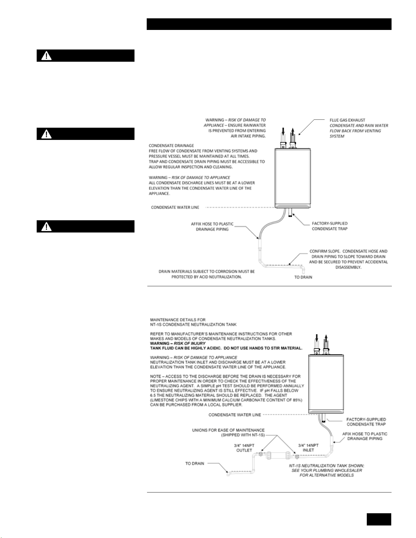
1.5.3 Further Installation Details
• Pipe the condensate drain to within 1" of a drain, or connect it to a condensate
pump.
• Slope the drainage line down to the drain at a pitch of 1/4" per foot, so that the
condensate runs towards the drain.
• Checkthecondensatetrapevery2months,andcleanandrellasnecessary.
T
Tankless
Water Heater
Figure 22: Condensate trap drainage
DANGER
The water in the condensate
neutralizer can cause severe
burns to the skin. Use extreme
caution when servicing the
condensate neutralizer. Wear
protective gloves and eyewear.
CAUTION
When a condensate
neutralization package
is installed, the pH of the
condensate discharge must
be measured on a regular
schedule to ensure the
neutralizing agent is active
and eective.
WARNING
If condensates are to be
discharged into building drain
piping materials that are subject
to corrosion, a neutralization
package must be used.
Tankless
Water Heater
Figure 23: Condensate neutralization tank

INSTALLATION AND OPERATION INSTRUCTIONS
1-22
TANKLESS WATER HEATER 199
1.6 WATER AND SPACE HEATING
APPLICATION
The following guidelines must be followed when using the water heater for both
potable water heating and space heating.
● Any piping or components used in the installation of this water heater in a
combination potable water and space heating application must be suitable for
use with drinking water.
● If this water heater is installed in an application intended to supply domestic
hot water needs and hot water for space heating purposes, DO NOT connect
the water heater to an existing heating unit or components of a heating
system that have previously been used with a nondrinking water system.
● Toxic chemicals such as those used for boiler treatment may be present and
will contaminate the drinking water supply causing possible health risks.
Never introduce toxic chemicals, such as glycol and those used for boiler
treatment into the system.
● This water heater is NOT approved as the dedicated space heating unit.
● This water heater must be used for combination applications with an air
handler only and not for indoor heating applications.
DANGER
When this system requires
water for space heating at
elevated temperatures (above
125°F [52°C]), a mixing or
tempering valve MUST BE
installed in the hot water
supply line to the house in
order to reduce the scald
hazard potential.
1-23
INSTALLATION AND OPERATING INSTRUCTIONS
TANKLESS WATER HEATER 199
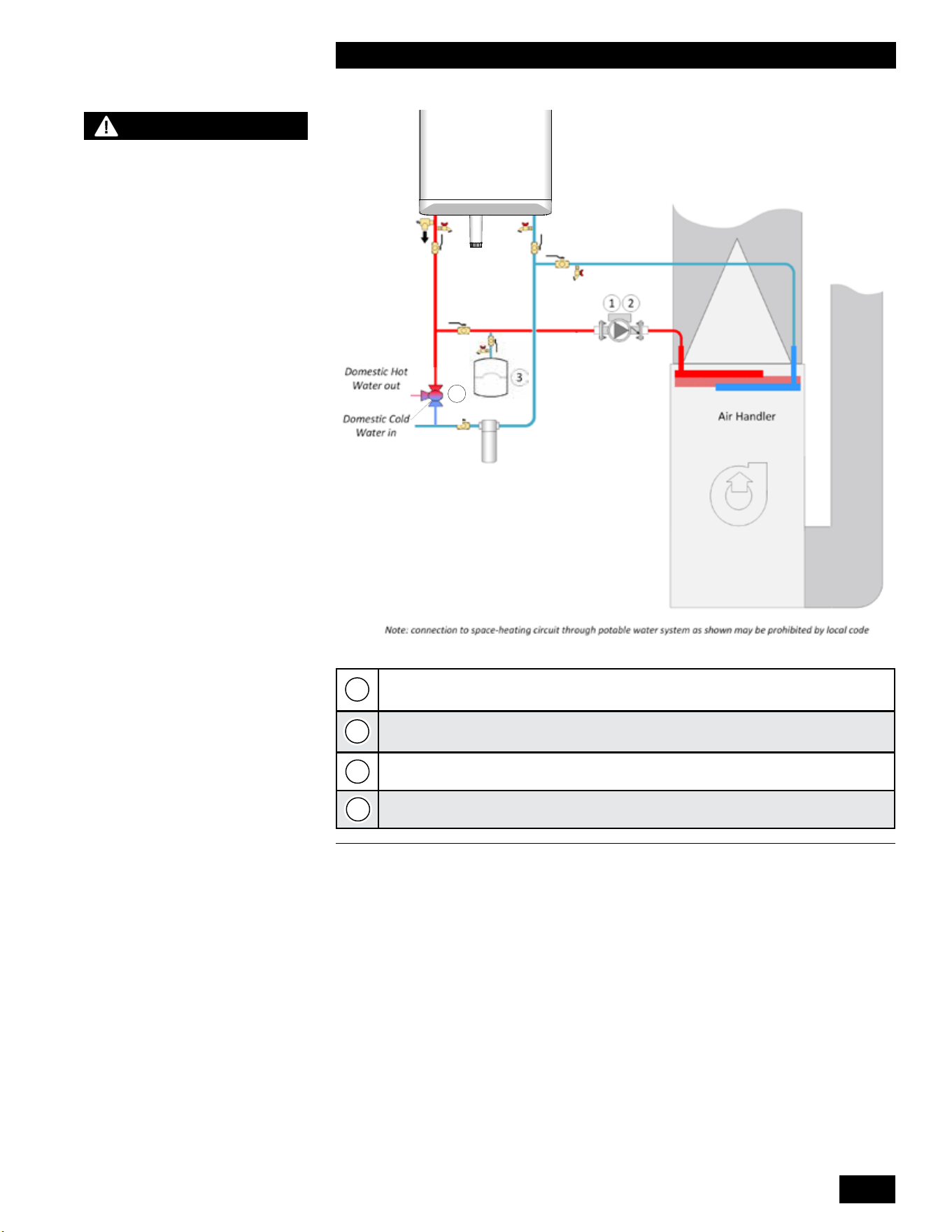
Tankless
Water Heater
4
Non-ferrous pump (sized for combined head loss of water heater and air
handler)
Check valve (may be built into pump)
Potable water expansion tank
Mixing valve
Figure 24: DHW and Air Handler Piping
NOTE
Connection to space-heating
circuit through potable water
system as shown may be
prohibited by local code.
1
2
3
4
INSTALLATION AND OPERATION INSTRUCTIONS
1-24
TANKLESS WATER HEATER 199
1.7 DOMESTIC HOT WATER SYSTEM
BURN
HOT
DANGER
°
Water temperature over 125°F (52°C) can cause severe burns instantly
or death from scalds.
°
Children, disabled, and elderly are at highest risk of being scalded.
°
See instruction manual before setting temperature at water heater.
°
Feel water before bathing or showering.
°
Temperature limiting valves are available, see manual.
WARNING
CAUTION
WATER HEATER INSTALLATION GUIDELINES
ADJUSTABLE TEMPERATURE SETTING
°
Hotter water increases the risk of scald injury. Before changing the temperature setting, see
instruction manual.
°
This unit must be installed in accordance with local codes, if any; if not follow the National
Fuel Gas Code, ANSI Z223.1/NFPA 54, or the Natural Gas and Propane Installation Code,
CAN/CSA B149.1, as applicable.
°
Failure to correctly install and operate this appliance can result in severe personal injury
or death.
°
The unit shall have a pressure relief valve installed within 6" [152mm] of the DHW HOT
outlet connection.
Refer to the unit’s User Manual before operating the relief valve.
°
The unit requires a pressure relief valve identified with the ASME V or HV symbol and
set to relieve at or below 150psi of domestic water pressure and a minimum relieving capacity
of 199,000 Btu/hr with 3/4" NPT threads. For safe operation of the unit, the relief valve
must not be removed from its designated point of installation or plugged.
°
Read and follow warnings and instructions.
°
Touch the panel above the white dot , then touch the Faucet . Adjust the water temperature
with the Plus + and Minus – then touch the Return button to save the changes.
1-25
INSTALLATION AND OPERATING INSTRUCTIONS
TANKLESS WATER HEATER 199
1.7.1 Domestic Hot Water System
ThisTanklessWaterHeaterhasacopperpipingcircuitforecientlygenerating
DomesticHotWater.Whenafaucetisopenedtodrawhotwater,waterowis
detectedwithaowsensorandtheunitresuptobegingeneratingdomestichot
water.
The heat exchanger has copper water passageways encased in the aluminum
heattransferblock.Thealuminumheatexchangeractsasaheatbuer,
eliminatingthe“coldwatersandwicheect”whenturningonandothewater
repeatedly.
While the
Tankless Water Heater
unit is less susceptible to lime scale build-up
thanotherunitsonthemarket,alwaysconsiderwaterqualityintheinstallation.
WestronglyrecommendtreatinghardwaterandadjustingthepHto6.5and
8.5. As a reference Table 5 represents some of the drinking water guidelines
published by the US EPA. Consult a water treatment adviser in your area to
assess your local needs. Proper water treatment will aid in the longevity of the
unitandensuremaximumeciencies.
When installing and maintaining the water heater, you must consider water
quality.Waterconditionsoutsideofthelevelsspeciedbelowmaydamagethe
water heater.
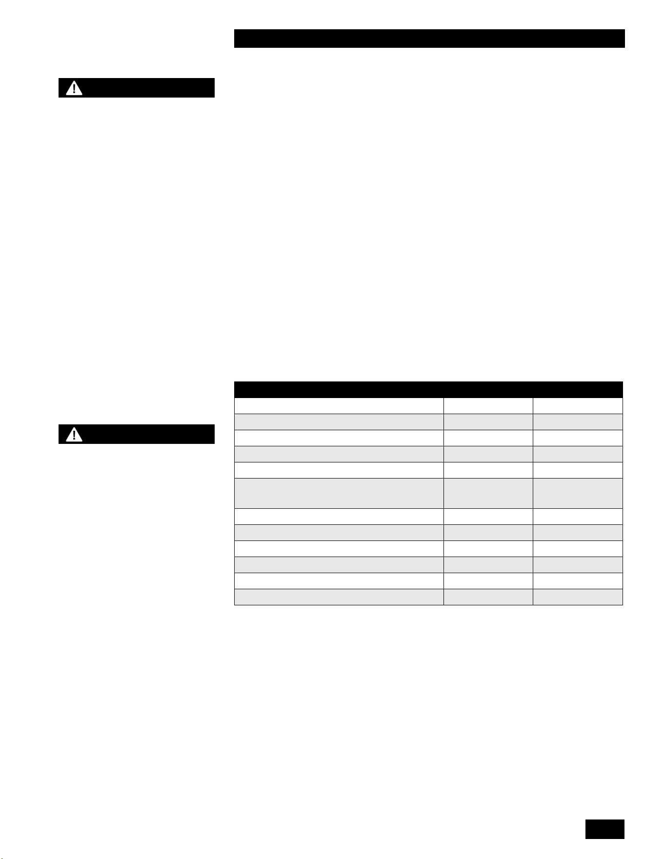
DESCRIPTION MAX MIN
Water Pressure 150 PSI 40 PSI
Programmable Water Temperature 149°F (65°C) 105°F (40°C)
Minimum DHW Flow Rate to Initiate Operation N/A 0.5 GPM
pH 8.5 6.5
Total Dissolved Solids (TDS) 500 mg/L
Total Hardness 250 mg/L 14.6 gr/
gal
Aluminum 0.2 mg/L 0.05 mg/L
Chlorides 250 mg/L
Copper 1 mg/L
Iron 0.3 mg/L
Manganese 0.05 mg/L
Zinc 5 mg/L
Table 5: Recommended Water Quality Guidelines
WARNING
HOT WATER CAN SCALD!
Water Temperatures over 125°F
/ 52°C can cause severe burns
instantly or death from scalds.
Children, disabled, and elderly are
at highest risk of being scalded.
• Never leave them unattended
in or near the shower, bathtub
or sink.
• Never allow small children to
use a not water faucet or draw
their own bath.
TO AVOID INJURY:
• Feel and adjust water
temperature before bathing or
showering.
•
Water drained from the system
drain valve may be extremely
hot.
• Make sure all connections are
tight.
• Direct water ow away from
any person.
NOTE
The limited warranty provided
with the water heater does not
cover defects, malfunctions
or failures resulting from
water conditions that are
not in accordance with the
specications in the table 5.
INSTALLATION AND OPERATION INSTRUCTIONS
1-26
TANKLESS WATER HEATER 199
Graph 1: Water Heater Pressure Drop
1.7.2 Domestic Hot Water Piping
The domestic water piping connections are located at the bottom of the unit, see
Figure 1b. The connections are
3/4" male NPT threads. The cold water inlet is on
the right side and the hot water outlet is on the left side.
Usetwowrencheswhentighteningeldpipingontotheboiler.Useonewrenchto
holdtheboilerttingstillwhiletighteningwithanotherwrench.
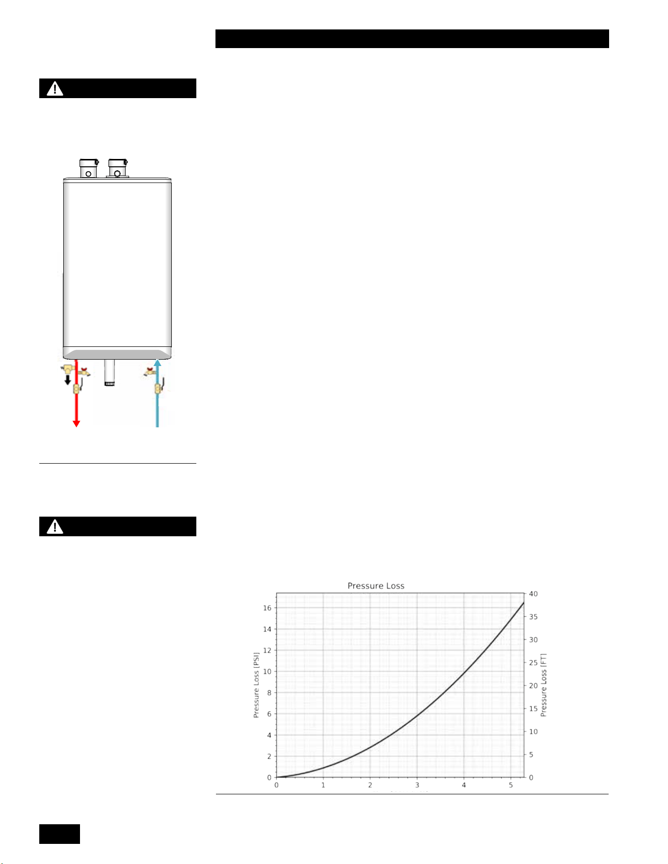
Aninstallersuppliedpressurereliefvalvemeetingthefollowingrequirementsmust
be installed:
● Maximum pressure rating of 150 PSI.
● Minimum capacity of 200,000 Btu/hr.
● On the domestic hot water outlet prior to any isolation valve.
Installation of a tankless water heater service valve kit with pressure relief valve is
recommended for ease of servicing the DHW coil in the future.
The
Tankless Water Heater
can be connected to the pressurized 1/2" or larger
domestic cold water supply piping and the domestic hot water piping in the home.
Theminimumdomesticwaterpressurerequiredis40PSIandrecommendedtobe
50PSI or higher. Generating domestic hot water with a water pressure lower than
40PSI reduces the amount of hot water generated and increases the risk of scaling
in the heat exchanger.
Thedomesticwaterpipingmustbeinstalledwithisolationvalvesandushingtaps
installed on both the cold and hot domestic connections.
Thermal expansion of the water in the domestic hot water (DHW) system can
occur without DHW usage such as in DHW Comfort Mode. As the small volume
of DHW in the heat exchanger is heated, it expands in volume and creates an
increase in the pressure within the water system. Check with your local water utility
company to determine if a check valve has been installed in the cold water line. If
acheckvalvehasnotbeeninstalled,theexpandingwatervolumeowsbackinto
the main, dissipating pressure. If a check valve has been installed, the expanding
water volume will increase the pressure within the homes water system. A DHW
expansiontankistypicallynotrequiredduetothelowvolumeofDHWintheheat
exchanger. If the pressure increase causes operation of the pressure relief valve, a
DHW expansion tank must be installed.
Thecoldwaterinletincludesaltertopreventcontaminantsfromfoulingthe
owsensorandheatexchanger.Seemaintenancesection4.1.12forcleaning
procedure.
WARNING
- Bacteria growth can develop
in domestic hot water tanks
and indirect water heaters if the
minimum water temperature is
not set high enough to prevent
its growth.
- Failure to support the boiler
tting with a second wrench
while tightening eld piping may
lead to boiler damage.
NOTE
See Domestic Hot Water
Warnings on page 1-25.
Figure 25: Overview of piping
connections
Tankless
Water Heater
DHW DCW
1-27
INSTALLATION AND OPERATING INSTRUCTIONS
TANKLESS WATER HEATER 199
DOMESTIC HOT WATER
DELIVERY
@ 67°F / 37.2°C temperature
rise
199,000 Btu/hr199,000 Btu/hr 5.4 GPM
CAUTION
A eld supplied thermostatic
mixing valve may be installed
on the domestic hot water
piping connections at the unit
or at the outlet of a domestic
hot water storage tank.
Aquastat
Combi Boiler
Combi Boiler
Tankless
Water Heater
Tankless
Water Heater
Figure 26: Tankless DHW Piping Options – concept drawing. This drawing is only a simple
schematic guide.
1.7.3 Tankless Domestic Hot Water with a Storage
Tank
The Tankless Water HeaterTankless Water Heater has the ability to connect a domestic hot water
storage tank to the unit to provide larger volumes of domestic hot water during
peak demands.
Thestoragetankispipedtotheunit’sdomestichotandcoldwaterpiping
connections (see B in Figure 26). You must install a bronze or stainless steel
pumptocirculatewaterfromthestoragetankthroughtheunit’sdomestichot
water coil.
Thestoragetankaquastatwillenablethepumpcausingtheunittorewhenthe
temperaturedropsbelowtheaquastatsetpoint.TheunitsDHWsetpointmust
besethigherthanthestoragetankaquastatsetpoint.Oncethestoragetank
temperaturehasreacheditssetpoint,theaquastatwilldisablethepump.
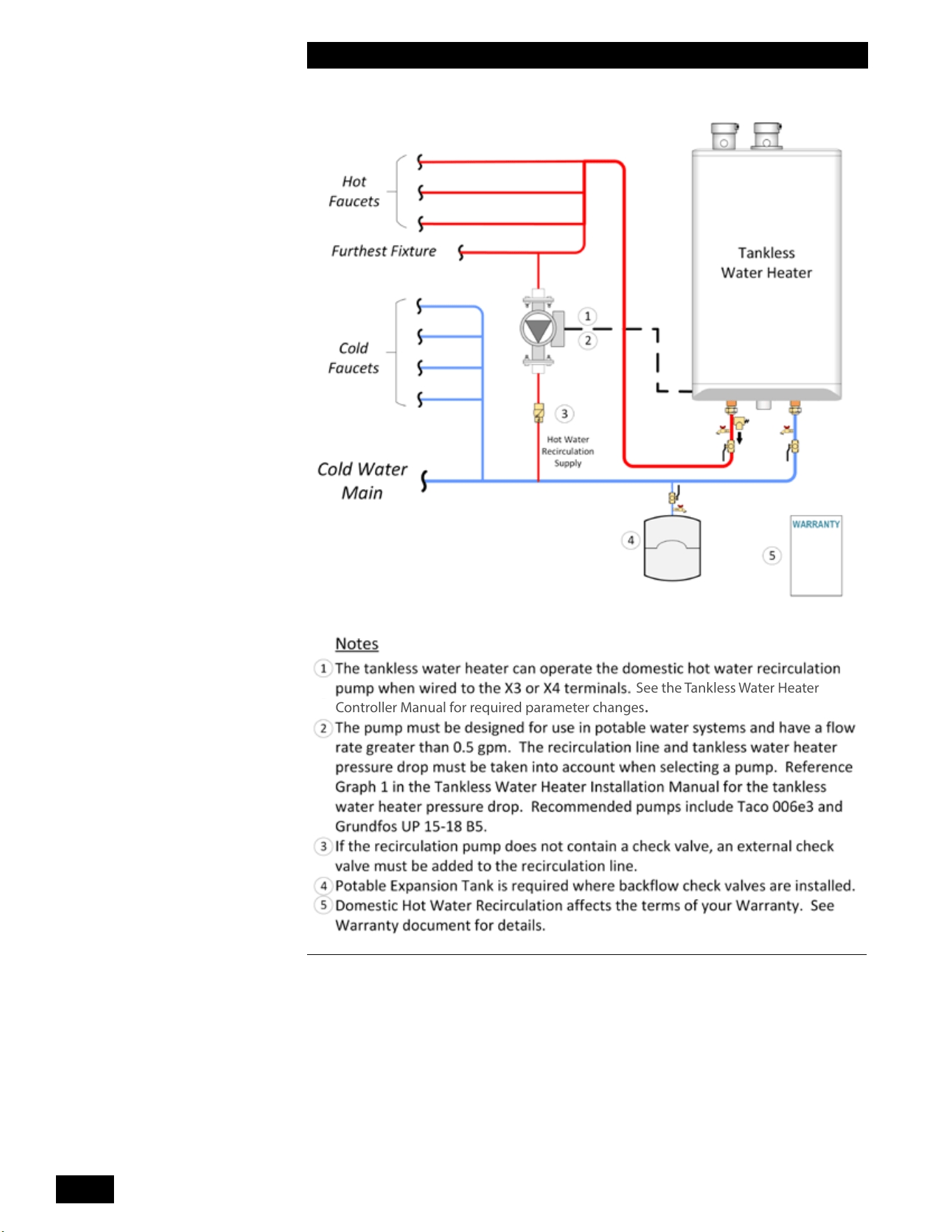
INSTALLATION AND OPERATION INSTRUCTIONS
1-28
TANKLESS WATER HEATER 199
Controller Manual for required parameter changes.
See the Tankless Water Heater
Figure 27: Typical DHW Recirculation piping – concept drawing. This drawing is only a
simple schematic guide
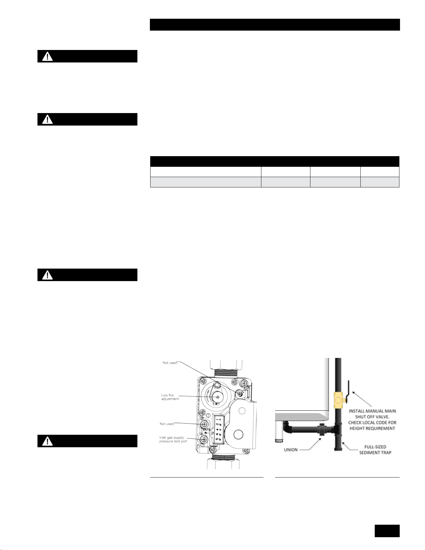
1-29
INSTALLATION AND OPERATING INSTRUCTIONS
TANKLESS WATER HEATER 199
1.8 GAS PIPING
The unit must have an inlet gas pressure of at least 4.0" w.c. for natural gas and
propane. For either fuel, the inlet pressure shall be no greater than 14.0" w.c.
Conrmthispressurerangeisavailablewithyourlocalgassupplier.
Theinletgasconnectionoftheunit’sgasvalveis¾"NPT(male).
Usetwowrencheswhentighteningeldpipingontotheboiler.Useonewrenchto
holdtheboilerttingstillwhiletighteningwithanotherwrench.
Adequategassupplypipingmustbeprovidedwithnosmallerthan1/2"IronPipe
Size and a 1" w.c. pressure drop, in accordance with the following chart:
MODEL 1/2" IPS 3/4" IPS 1" IPS
199,000 Btu/hr (Natural Gas) 10' 40' 150'
199,000 Btu/hr (Propane) 30' 125' 400'
Table 6: Maximum Pipe Length (ft)
Gaspipingmusthaveasedimenttrapaheadoftheunit’sgasvalve(see Figure
29). Amanualshutovalvemustbelocatedoutsidetheunit,inaccordancewith
localcodes/standards.Allthreadedjointsingaspipingmustbemadewithan
approved piping compound resistant to the action of natural gas/propane. Use
proper hangers to support gas supply piping as per applicable codes.
Before placing the boiler into operation, the boiler and all gas connections must
be checked for leaks.
• Closethegasshutovalveduringanypressuretestingequaltoorlessthan½
psi (3.5 kPa).
• Disconnecttheboilerandgasshutovalvefromthegassupplyduringany
pressure testing greater than ½ psi (3.5 kPa).
The gas valve is provided with pressure taps to measure gas pressure upstream
(supply pressure) and downstream (manifold pressure) of the gas valve (see
Figure 28).Notethatmanifoldpressurevariesslightlyinaccordancewithring
rates with the modulating series units, but will always be close to 0" w.c.
CHECK LOCAL CODE FOR
SIZE REQUIREMENTS
WARNING
This tankless water heater
can burn either natural gas
or propane. Refer to section
3.3 for further instruction. If
converting a unit from one
fuel to another, you must
order a conversion kit prior
to the conversion. Install the
conversion kit according
to the detailed instructions
supplied with the kit. Failure
to perform the required fuel
conversion correctly can
result in serious injury or
death.
NOTE
It is essential to check gas
supply pressure to each
unit with a manometer or
other high-quality precision
measuring device. Pressure
should be monitored before
ring the unit, when the
regulator is in a “lock-up”
condition and during operation,
throughout the unit’s full
modulation range.
Pay special attention to retrot
situations where existing
regulators may have an over-
sized orice and/or worn seats,
causing pressure “creep” and
high lock up pressures.
WARNING
Failure to support the boiler
tting with a second wrench
while tightening eld piping
may lead to boiler damage.
Figure 28: Gas Valve
WARNING
Do not check for gas leaks
with an open ame, use the
bubble test. Failure to use
the bubble test or check
for gas leaks can cause
substantial property damage,
serious injury, or death.
Figure 29: Gas Piping
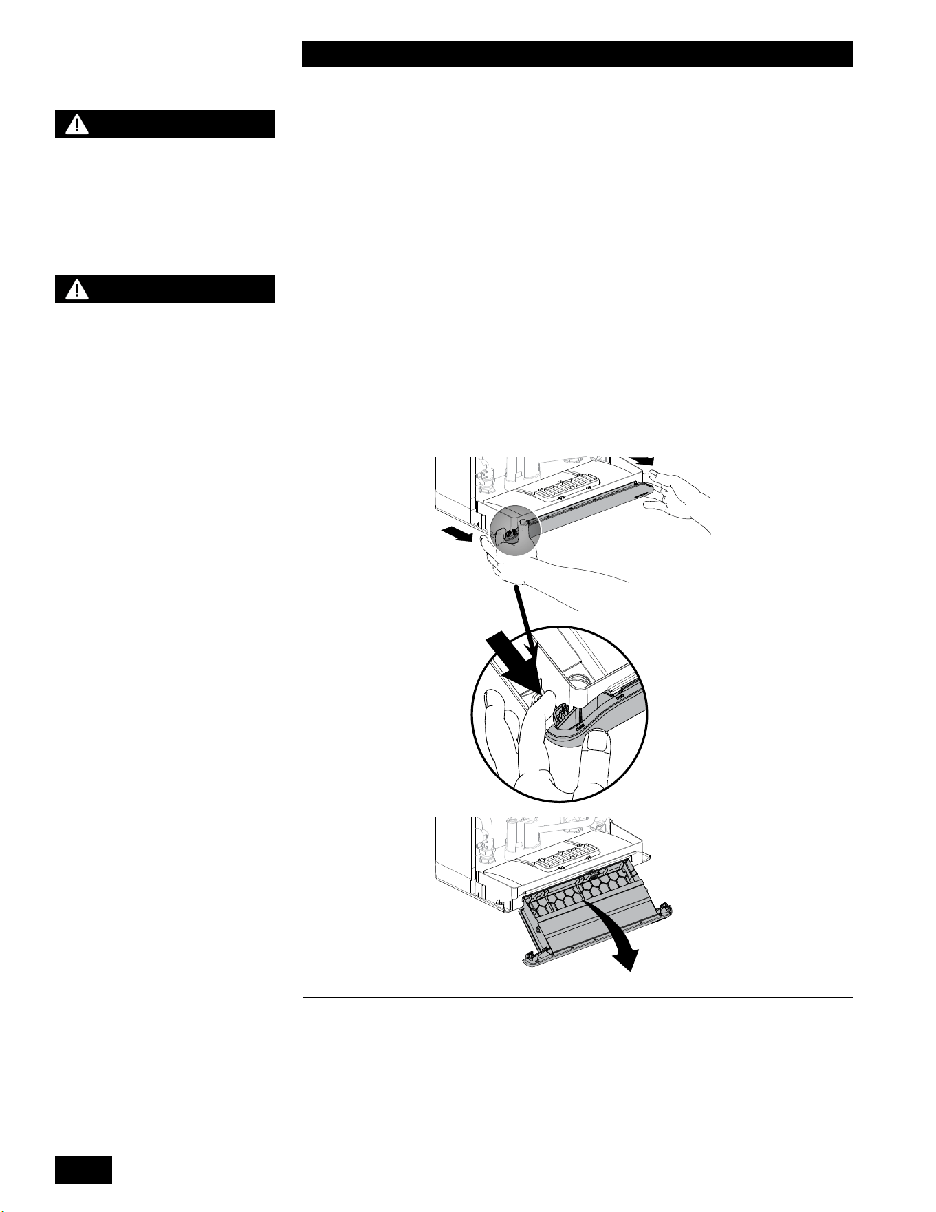
INSTALLATION AND OPERATION INSTRUCTIONS
1-30
TANKLESS WATER HEATER 199
NOTE
The unit (like any modern
appliance that contains
electronic equipment), must
have a “clean” power supply,
and can be disabled by power
surges and spikes, lightning
strikes and other forms of
severe electrical “noise”.
Power conditioning equipment
(surge protectors, APC or UPS
devices) may be required in
areas where power quality is
suspect.
WARNING
Do not apply power to any
connection point on the
controllers terminal strips.
A hazardous situation could
occur resulting in possible
serious injury or death.
1.9 ELECTRICAL CONNECTIONS
Electrical wiring to the unit (including grounding) must conform to local electrical
codes and/or National Electrical Code, ANSI/NFPA No. 70 – latest edition in the
US or The Canadian Electrical Code, C22.1 - Part 1 in Canada.
1.9.1 120VAC Line Voltage Hook-up
(Refer to Section 6.2.Wiring Diagram on page 6-4). Connect the unit to the grid
power, using the supplied appliance plug in a separate non GFCI fused circuit
andon/oswitchwithinsightoftheunit.
1.9.2 Accessing Controller Terminal Strip
Pulloutonthetwocontrolmoduleretainingtabsthenipdownthecontrolto
access the terminal strip.
1.9.3 Power Quality and Electrical Protection
In areas of unreliable power, appropriate surge protectors and/or power
conditioningequipmentshouldbeinstalledtoprotecttheunit.
Figure 30: Pullling out the tray
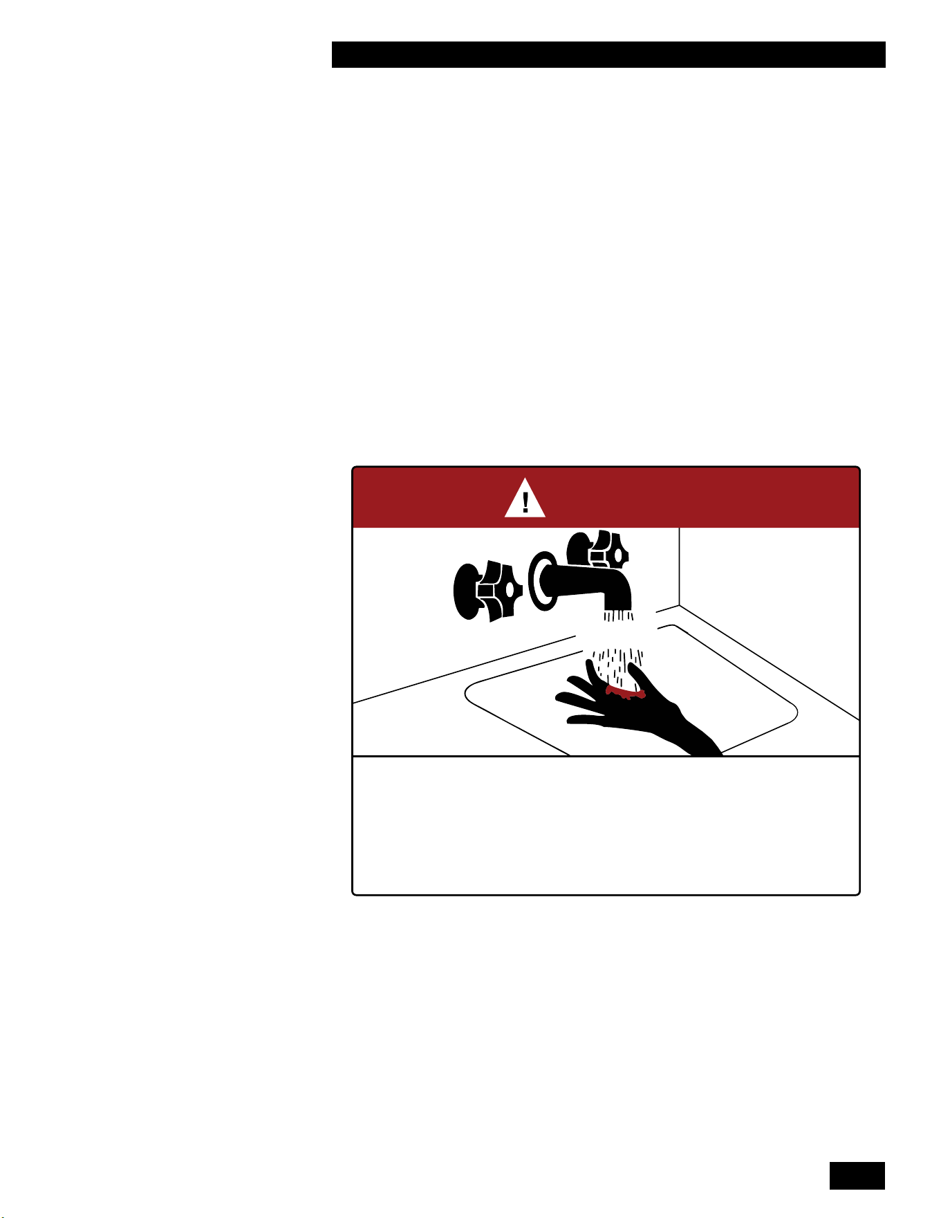
2-1
UNIT SYSTEM OPERATION
TANKLESS WATER HEATER 199
2.0
UNIT SYSTEM OPERATION
2.1 GENERAL
The Tankless Water Heater can be used as a tankless water heater, with or
without a storage tank.
Theunitisequippedwithanelectronicunitcontrollerthatignitestheburnerand
continuouslymonitorstheamethroughouteachcallforheat.Thecontroller
also displays the current operating conditions of the unit and any error messages
should a problem occur.
Theunit’scontrolleralsoprovidesfrostprotection.Whentheunit’sheat
exchanger temperature becomes too low the burner switches on to keep the heat
exchanger warm. Ensure that the condensate trap is protected from freezing. The
unit must be installed indoors in a heated space.
BURN
HOT
DANGER
°
Water temperature over 125°F (52°C) can cause severe burns instantly
or death from scalds.
°
Children, disabled, and elderly are at highest risk of being scalded.
°
See instruction manual before setting temperature at water heater.
°
Feel water before bathing or showering.
°
Temperature limiting valves are available, see manual.
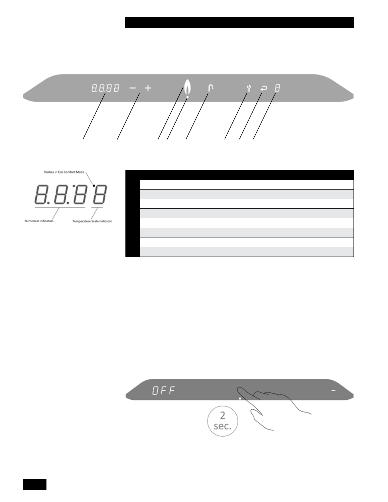
INSTALLATION AND OPERATION INSTRUCTIONS
2-2
TANKLESS WATER HEATER 199
2.2 CONTROL
ICON FUNCTION
A
Numerical Display Main Display
B
Plus & Minus TemperatureAdjustment
C
Flame Burner ON Indicator
D
Dot Power ON Indicator
E
Faucet DHW Indicator
F
Wrench Service / Reset
G
Return Arrow Enter / Save
H
Numerical Display Service Display
Table 7: Controller Indicators and Touch Pad
2.3 INSTALLER INTERFACE
2.3.1 Turning Appliance ON/OFF
To turn on the unit, touch the area above the dot for 2 seconds. Now only the dot is
illuminated.
Toturnotheunit,touchtheareaabovethedotfor2seconds.Adashappearson
the right and the text “OFF” is displayed on the left.
Controller turn on
A G HF
EC
D
B
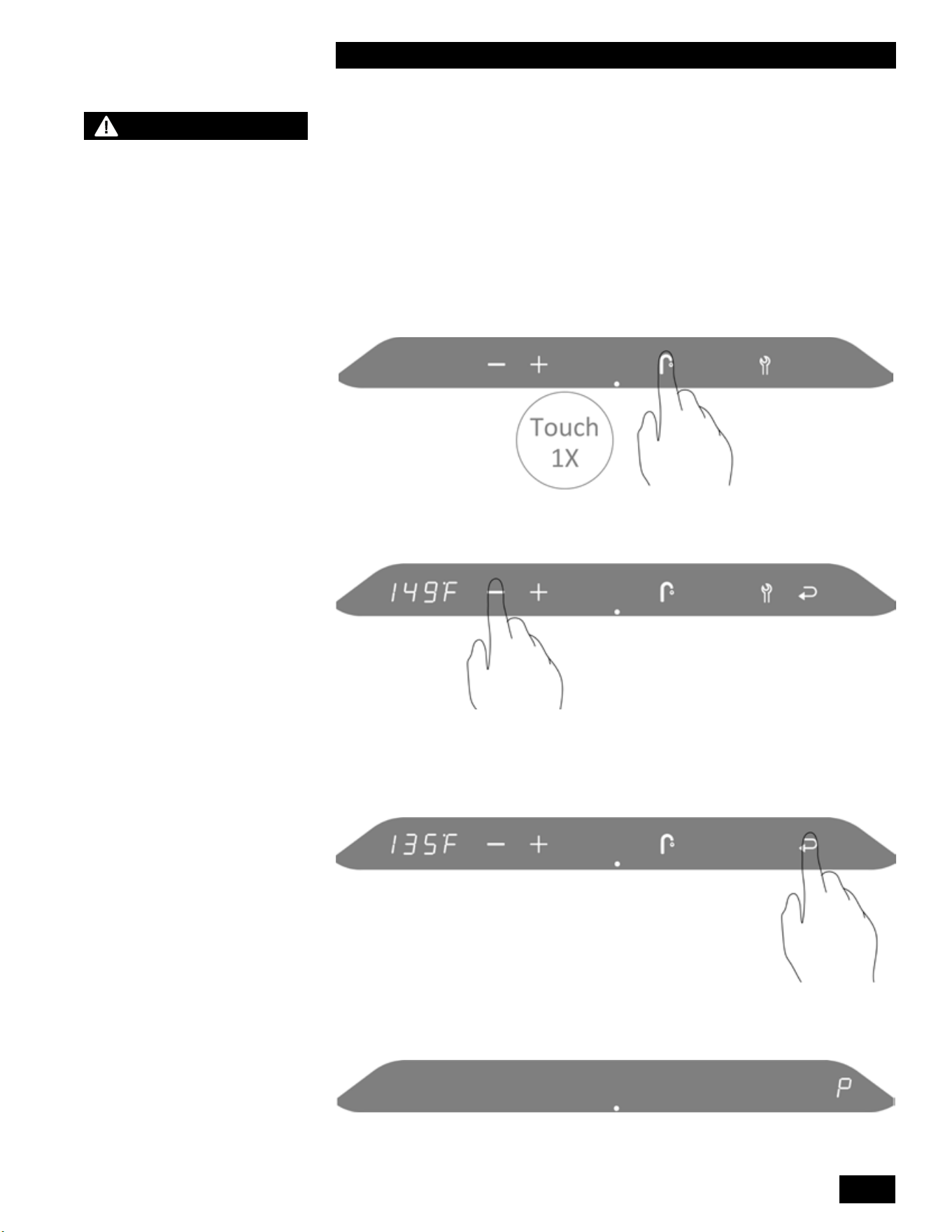
2-3
UNIT SYSTEM OPERATION
TANKLESS WATER HEATER 199
2.3.2 Programming Mode
There are two parameters available in the User Setup Menu.
Thecontrollerhasvelevels:UserMenu,InstallerMenu(code15),aMaster
Installer Menu (code 20), RF Menu (code 30) and Cascade Menu (code 35). See
included Controller Manual for details.
Adjusting the Domestic Hot Water Temperature
To access the main menu:
1. Touch the area above the dot.
2. Touch the Faucet button.
DHW menu B
3. To change the DHW target temperature, touch the Plus or Minus buttons.
4.
• To save the changes, touch the Return button.
• To exit without saving the changes, touch the area above the dot.
“P” to the right of the screen indicates that the changes have been saved.
NOTE
The domestic hot water
thermostat is adjusted to its
lowest temperature position
when shipped from the
factory. It’s recommended to
set the domestic hot water
thermostat to 120°F/49°C as
an initial setting and further
adjust as required. For
energy ecient operation,
this setting should be set
as low as practical for the
consumer’s needs.
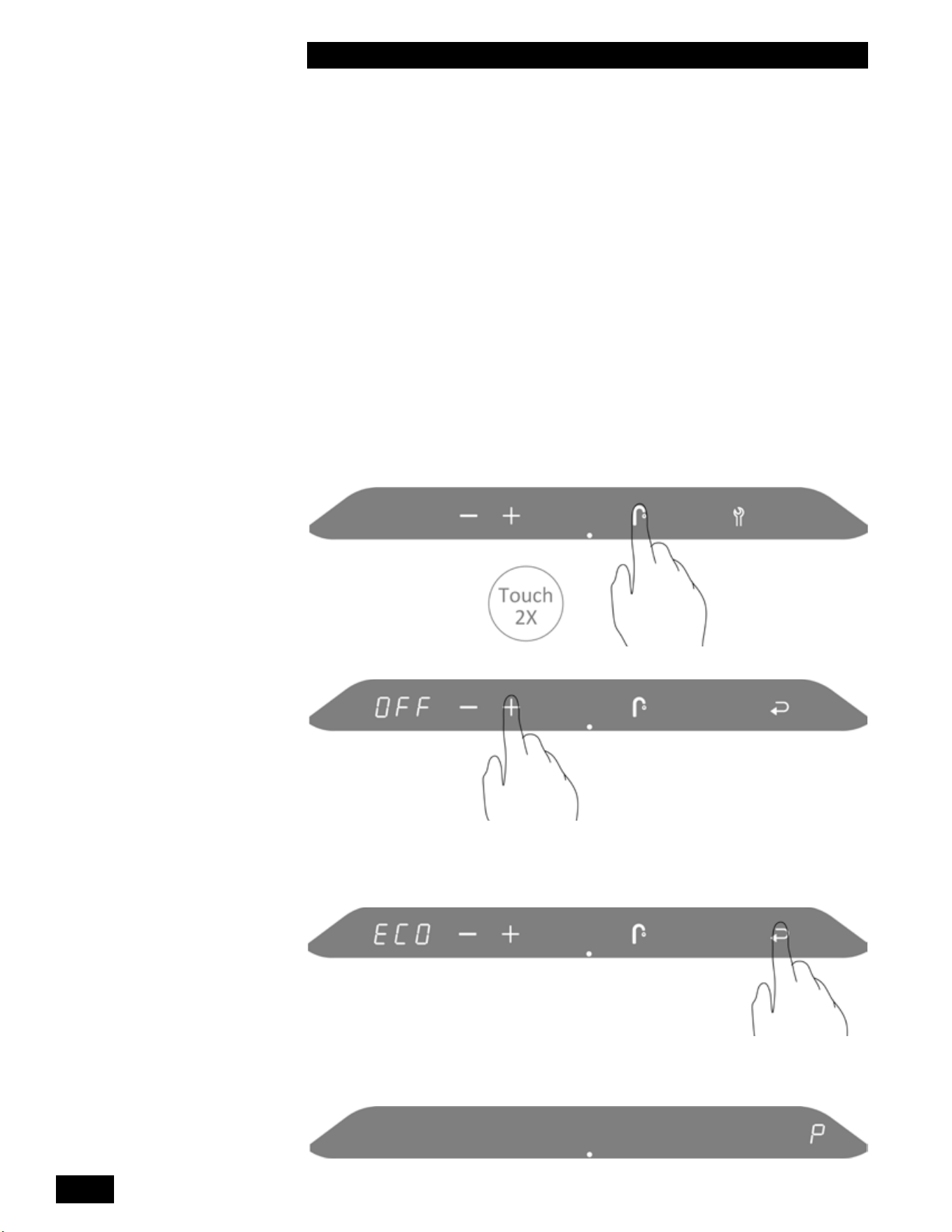
INSTALLATION AND OPERATION INSTRUCTIONS
2-4
TANKLESS WATER HEATER 199
2.4 TANKLESS DOMESTIC HOT WATER
MODES
2.4.1 Tankless Domestic Hot Water - Standard and
ECO Comfort Modes
Standard Mode (OFF): The heat exchanger will not maintain its domestic hot
water temperature between demands for hot water.
Comfort Mode (ON): The heat exchanger is maintained at the DHW
temperature.
ECO Comfort Mode (ECO): This mode operates like the Comfort Mode but has
the added advantage of learning when the domestic hot water is used. During the
low use periods, the heat exchanger is allowed to cool.
To switch between the 3 modes:
1. Touch the area above the dot.
2. Touch the Faucet button twice.
3. To change the DHW mode, touch the Plus or Minus buttons.
4.
• To save the changes, touch the Return button.
• To exit without saving the changes, touch the area above the dot.
“P” to the right of the screen indicates that the changes have been saved.
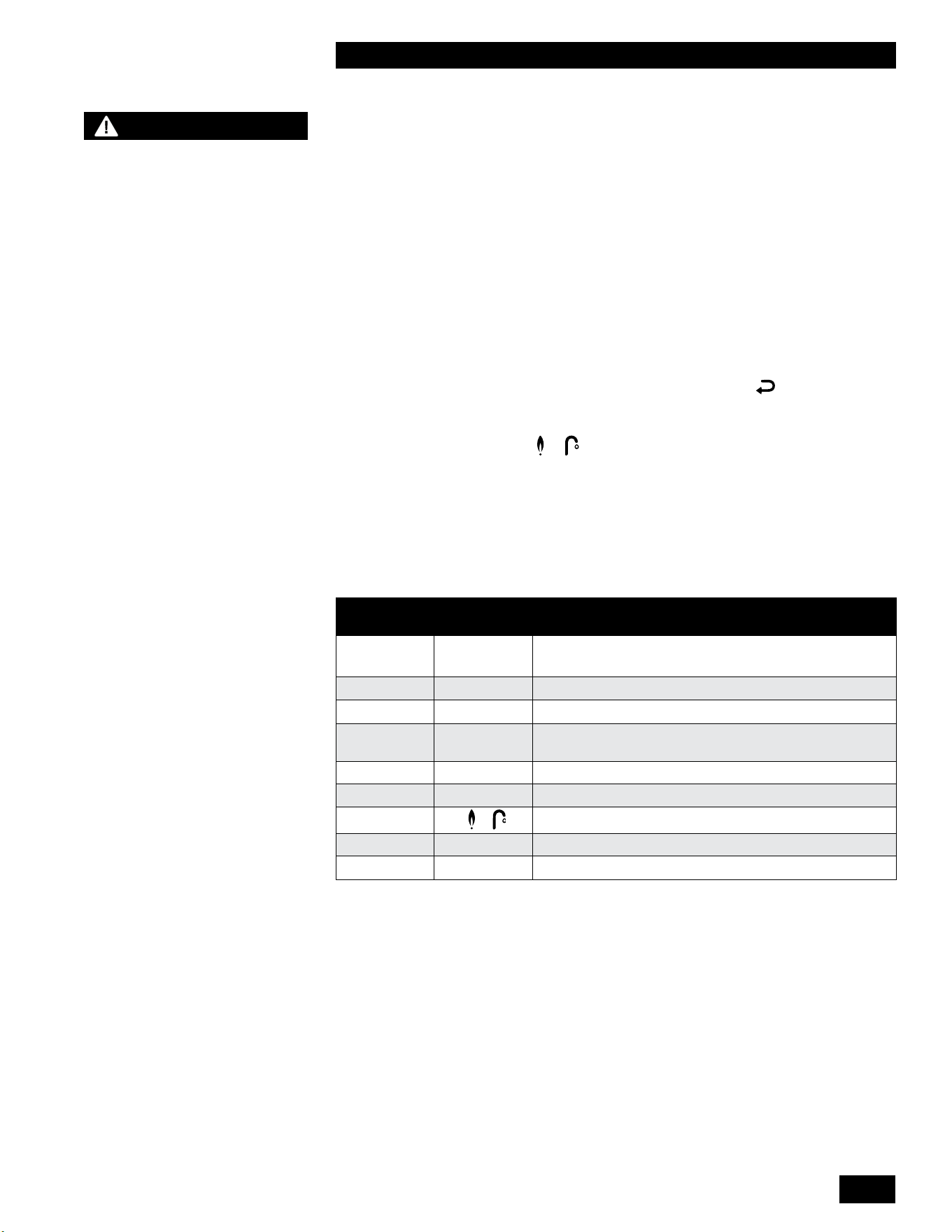
2-5
UNIT SYSTEM OPERATION
TANKLESS WATER HEATER 199
2.5 SEQUENCE OF OPERATION
When the unit is powered up the controller enters a self-diagnostic mode, and
displays the controller software version in the main display.
Thesequenceofoperationisasfollows:
1. The unit receives a call forfordomestichotwaterheatingfromtheinternalow
sensor.
2. The unit performs a safety check and energizes the fan for a pre-purge
(Service Display = 3).
3. Once the 5-second pre-purge is complete, the unit enters a 5-second trial for
ignition (Service Display = 4). If the unit fails to ignite, the unit will complete
another 5-second pre-purge then 5-second trial for ignition. This is repeated
4 times before a hard lock-out occurs. The Return button must be pressed
to reset the controller and begin another trial for ignition.
4. Oncetheburnerislitandamehasbeenproventheunitoperatesasitis
programmed (Display=+fordomestichotwater).
5. If the unit exceeds its target temperature and there is still a call for hot water
theburnerwillturno.(Service Display = 1)
6. If the burner is on to maintain the heat exchanger temperature for DHW
Comfort mode (Service Display = 7).
7. If the burner is on for frost protection (Service Display = 9).
MAIN
DISPLAY
SERVICE
DISPLAY
DESCRIPTION
OFF - The unit is OFF. Press the space above the dot for 2
seconds to turn on the unit
.
(blank) (blank) No Call for Hot Water - Standby
XXX
1
Unit water temperature exceeds target, call still present
XXX 2 Self-test – When power is applied to the unit the
controller enters a self diagnostic mode for 5 seconds
XXX 3 Fan Pre-purge and Post-purge
XXX 4 Trial for Ignition and Flame Proving
XXX + Heating – DHW
XXX 7 Burner on for DHW Comfort mode
XXX
9
Freeze Protection mode
Table 8: Operating Display and Service Display Codes.
NOTES
The unit is equipped with
a frost protection feature.
This feature operates the
unit’s burner to help protect
the unit from freezing. If the
unit is in a hard lock-out
condition the burner will not
operate. The manufacturer is
not responsible for damages
to the unit, and/or related
components, nor property
damages that may result from
freezing conditions.
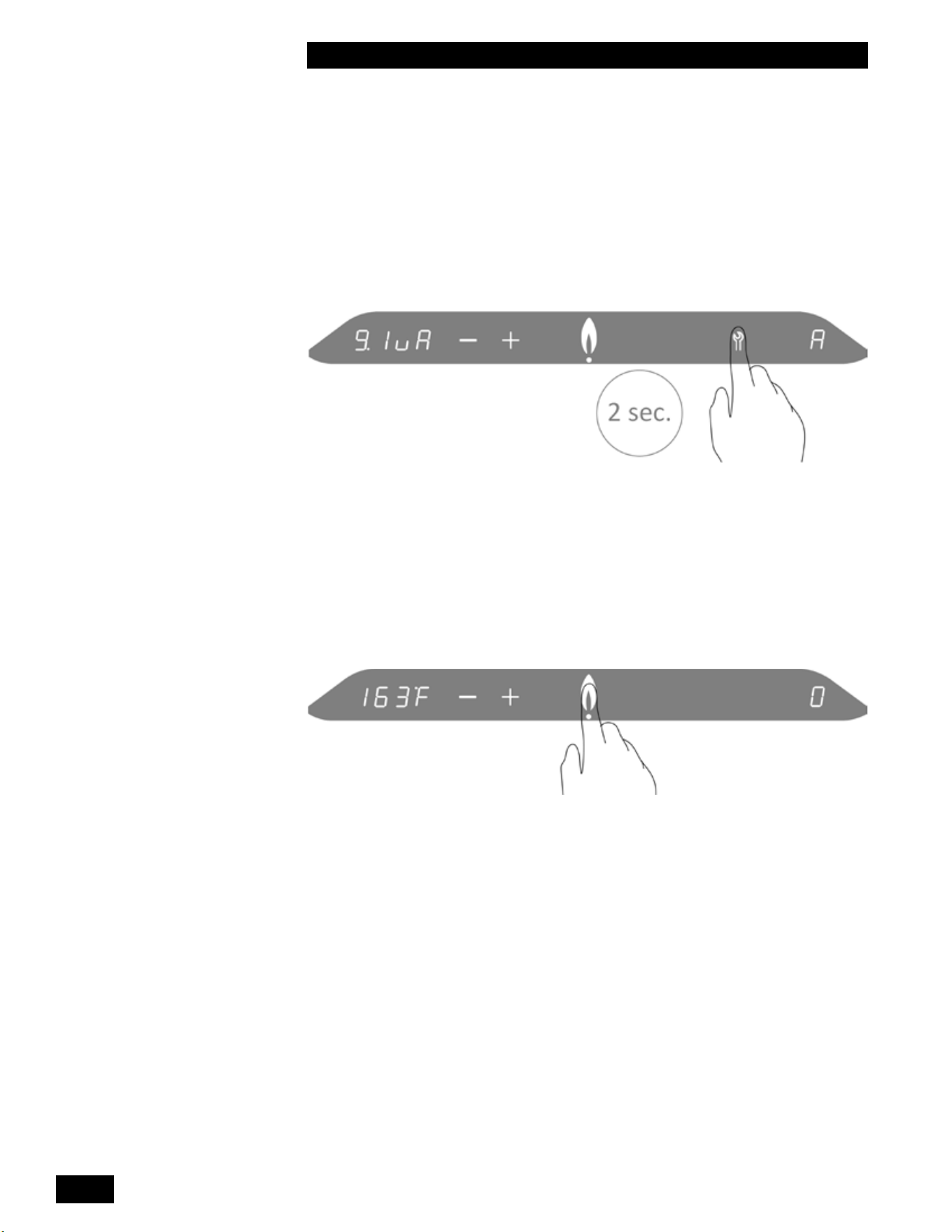
INSTALLATION AND OPERATION INSTRUCTIONS
2-6
TANKLESS WATER HEATER 199
2.6 ACCESSING THE INFORMATION MENU
The Information menu provides real time operating information to assist with
troubleshooting.
To access the Information menu:
1. Touch the area above the Dot.
2. Touch and hold the Wrench button for two seconds, let go when the minus,
plus, and wrench are displayed.
3. Again, touch and hold the Wrench button for two seconds to enter the
information menu.
See table 9 for a list of codes and corresponding description.
4. To scroll through the list of codes, use the Minus or Plus button.
5. To exit the information menu and return to the Service menu, press the area
above the Dot.
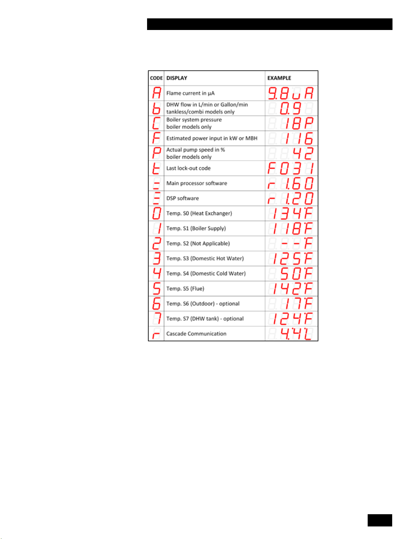
2-7
UNIT SYSTEM OPERATION
TANKLESS WATER HEATER 199
See below for a description of the codes:
Table 9: Information Menu
Notethatdisplayparametersmaydierdependingontheconguration.Wherethereisno
DHW sensor, the display reading can be ignored.
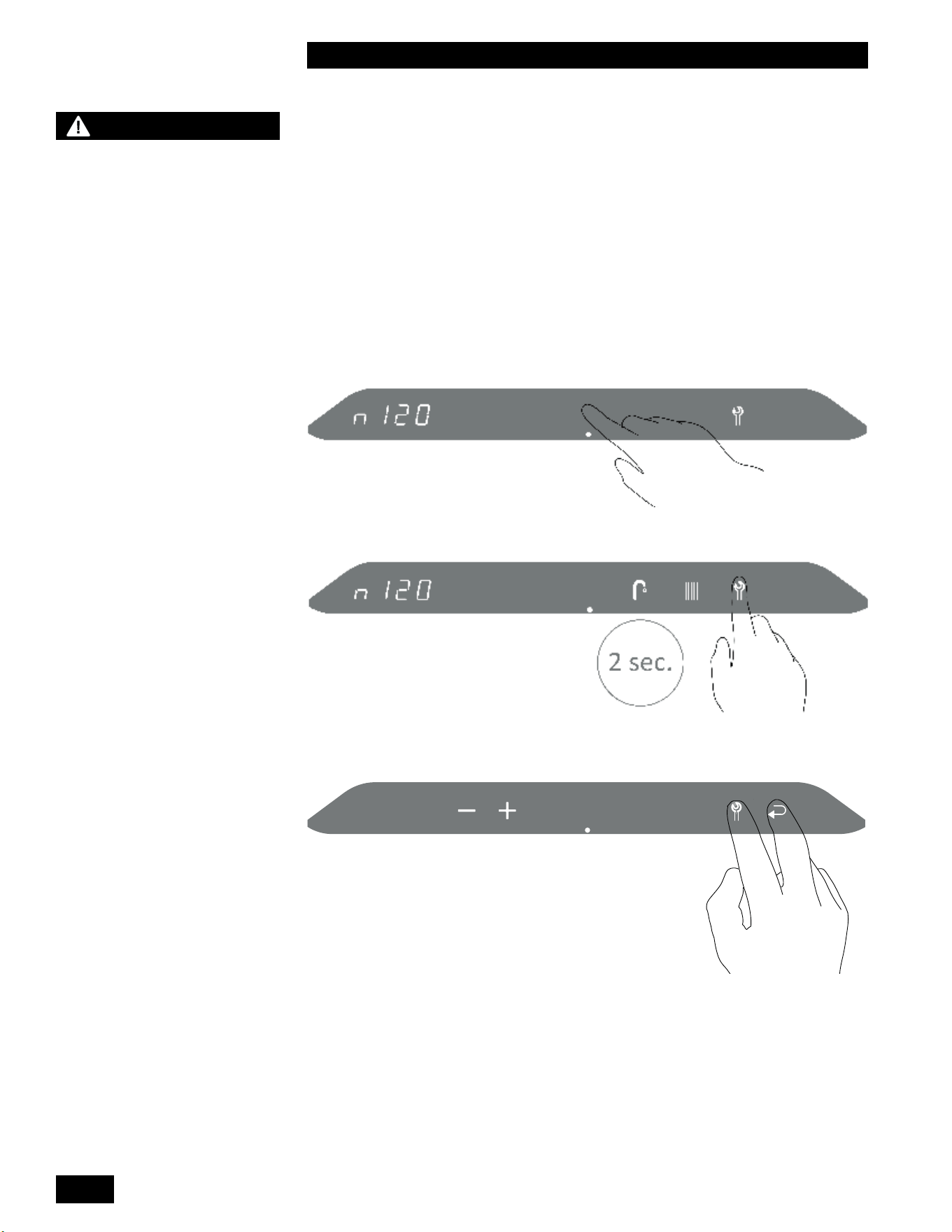
INSTALLATION AND OPERATION INSTRUCTIONS
2-8
TANKLESS WATER HEATER 199
2.7 RESETTING THE MAINTENANCE
COUNTER
Inspectionoftheunitmustbeperformedannuallybyaqualiedservice
technician. This unit includes a maintenance counter which tracks the amount of
fuel burned within a two year period to ensure maintenance is performed if usage
exceeds typical residential usage. When above average usage occurs within a
twoyearperiod,anoticationcodewillbedisplayed.
Toresetthemaintenancecounterandclearamaintenancenoticationcode:
1. Touch the area above the dot.
2. Touch the wrench for two seconds until the return button appears.
3. Touch wrench and return buttons together.
CAUTION
The maintenance counter
must only be reset after
performing the maintenance
procedures in Section
4.0 Maintenance of this
manual. Failure to perform
maintenance can result in a
hazardous condition.
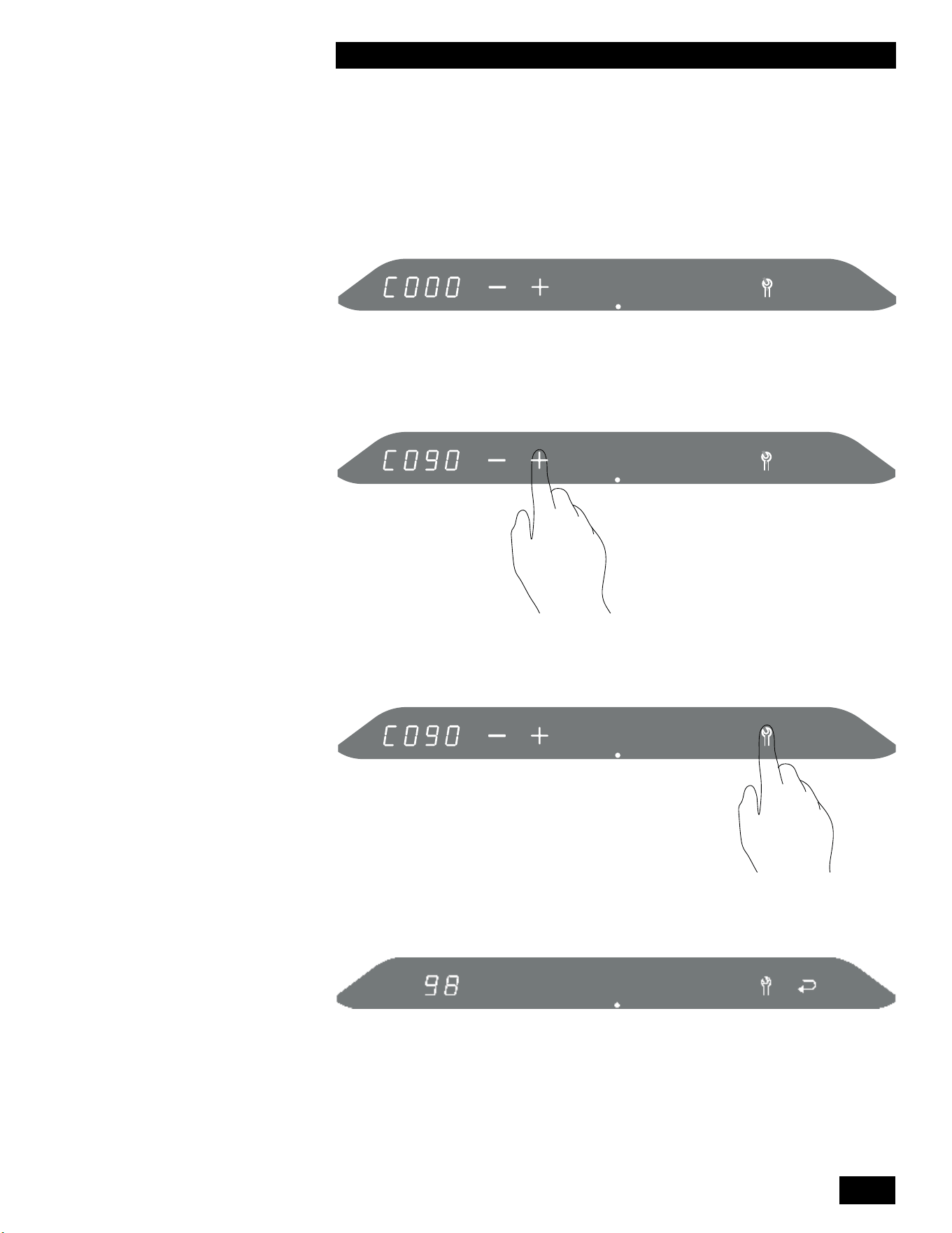
2-9
UNIT SYSTEM OPERATION
TANKLESS WATER HEATER 199
The code numbers are displayed in the left numerical display.
4.ChangeC000toC090bytouchingthe+button.
5. Touch wrench to enter the maintenance menu.
The current maintenance counter value is displayed in the left numerical display.
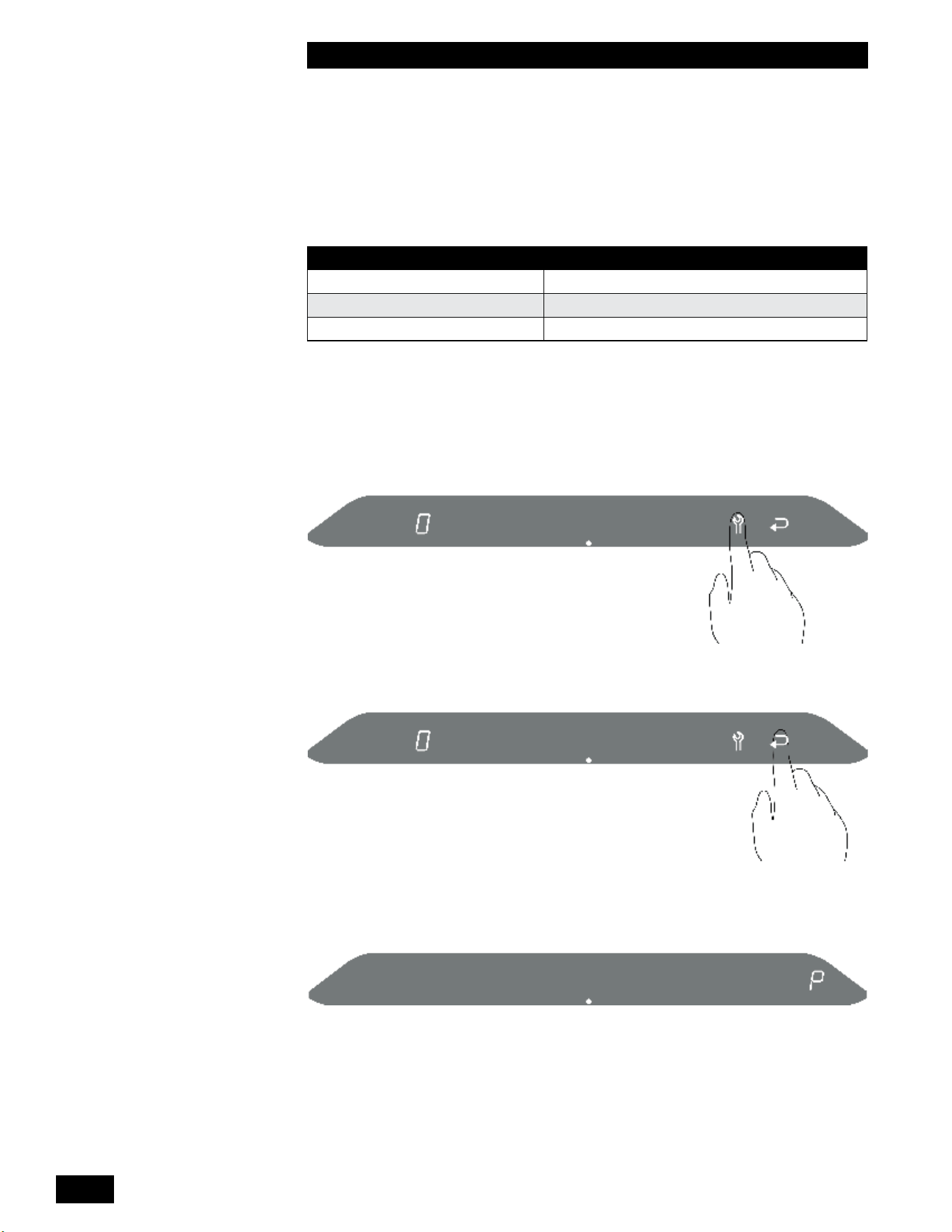
INSTALLATION AND OPERATION INSTRUCTIONS
2-10
TANKLESS WATER HEATER 199
INSTALLATION AND OPERATION INSTRUCTIONS
2-10
TANKLESS WATER HEATER 199
Thefollowingnoticationswillbedisplayedasthetimeformaintenance
approaches.
MAINTENANCE COUNTER NOTIFICATION CODE
80 n120 - Maintenance recommended
100 n121-Maintenancerequired,limitedDHWoutput
120 n122-Maintenancerequired,noDHWoutput
Thenoticationcodewillbedisplayedfor30secondsandthewrenchwillash.
Pressthewrenchbuttontoseethenoticationcodeagainafter30seconds.
6. Touch the wrench to reset the maintenance counter to 0.
7. Touch return to resume normal operation.
Pwillbebrieydisplayedontherightscreentoindicatethechangehasbeen
stored.
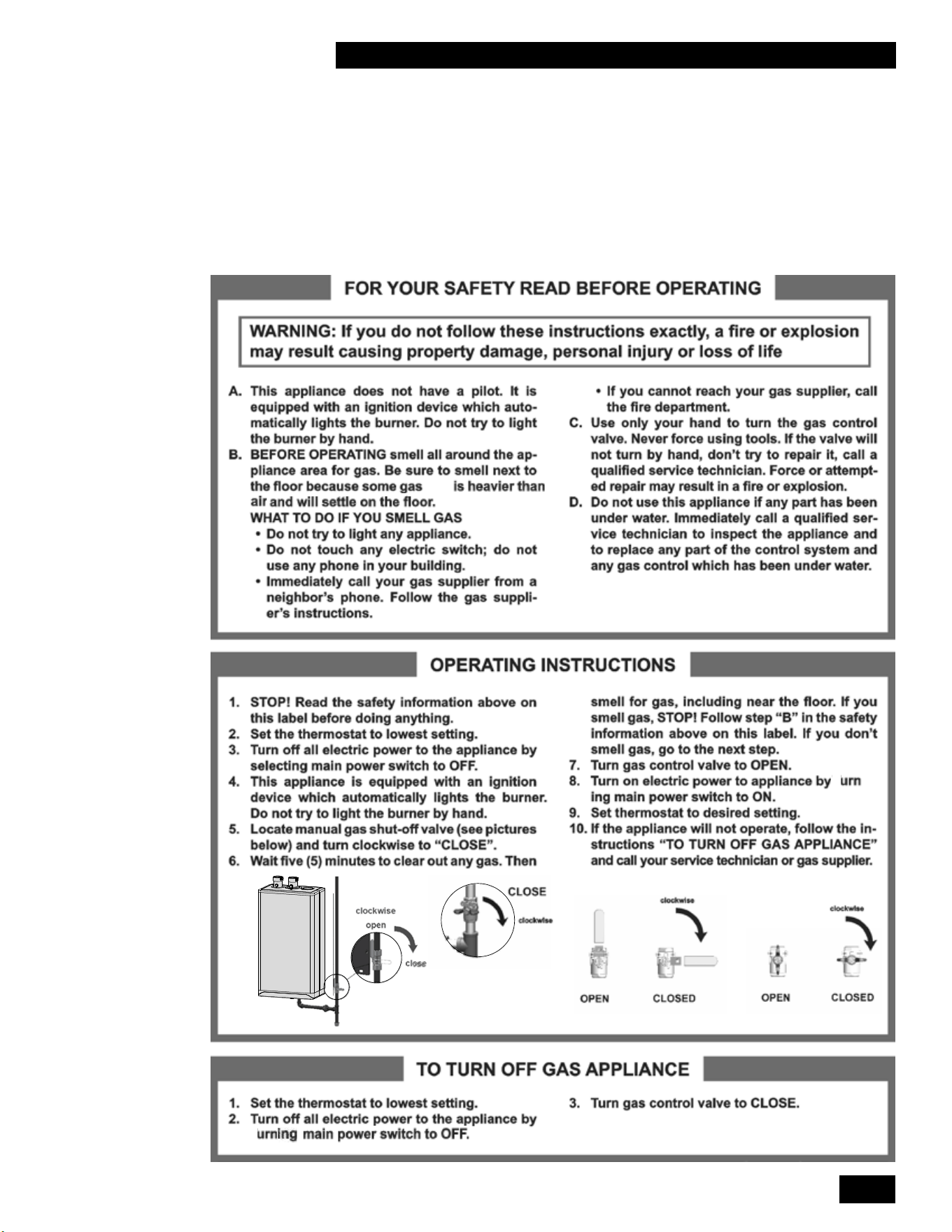
3-1
STARTUP AND COMMISSIONING
TANKLESS WATER HEATER 199
3.0 STARTUP & COMMISSIONING
3.1 LIGHTING & SHUTTING DOWN THE UNIT
(LP)
t
-
t
t

INSTALLATION AND OPERATION INSTRUCTIONS
3-2
TANKLESS WATER HEATER 199
INSTALLATION AND OPERATION INSTRUCTIONS
3-2
TANKLESS WATER HEATER 199
3.2 PRIOR TO START-UP
3.2.1 Pre-Ignition Checks
1. Fill the condensation trap. Ensure the venting system is complete and seal-
tested.Conrmthatanycommonventingsystemattheinstallationsiteis
isolated and independent of the unit, that any holes left from removal of a
previousunithavebeensealed,andthatanyresizingoftheolduehas
been done.
2.
Conrmthatthepressurereliefvalveisinstalledanddischargelineisdirected
downward to a safe point of discharge
3. Checktoseethatadequategaspressureispresentattheinletgassupply
testport.Withtheunitgasvalveshuto,usingaTorx15screwdriver,open
the test port by turning 1 full turn counterclockwise. Connect a manometer
andopenthemanualgasvalve.Requirementsareminimum 4" w.c. and minimum 4" w.c. and
maximum 14" w.cmaximum 14" w.c. Check that there are no gas leaks.
4. Performanalcheckofelectricalwiringandprovidepowertotheunitto
initialize operation.
3.2.2 Test Ignition Safety Shutoff
Withtheunitinoperation,testtheignitionsystemsafetyshutodeviceby
shuttingothemanualgasvalveimmediatelyoutsidetheunitcase.Ensurethat
theunithasshutoandthattheappropriateerrorinformationisdisplayedonthe
main display screen. To restart the unit, press the Reset button.
3.3 COMMISSIONING
The Tankless Water Heater is factory calibrated to operate with natural gas at
sealevel.HighFirecombustionissetbytheoriceinstalledandisnoteld
adjustable.Alowcaloricvaluenaturalgasorice(SeeTable10)isavailablefor
locationswherethenaturalgascaloricvaluefallsbelowtheexpectedrangeof
950-1100BTU/Ft3.Consultyourlocalfuelproviderforyourfuel’scaloricvalue.
Lowreiseldadjustableviathelowreadjustmentonthegasvalvebutmust
bedonewithcaution.Nomixtureadjustmentmaybeperformedunlessdoneby
aqualiedtechnicianusingaproperlyfunctioningandcalibratedcombustion
analyzer.
This unit can burn either natural gas or propane if equipped with the
correct specied orice. Examine the rating plate of the unit to ensure it
is congured for the fuel you are using. If the unit is to be converted from
natural gas to propane or from propane to natural gas a fuel conversion kit
must be installed. For the correct fuel conversion kit part number, see the
table below:
MODEL NATURAL GAS
TO PROPANE
PROPANE TO
NATURAL GAS
LOW CALORIFIC
NATURAL GAS
199,000 Btu/hr P-081014 P-081024 P-081414
Table 10: Fuel conversion kits
The gas valve will automatically de-rate the maximum input by approximately 2%
per1,000’abovesealevel.Thegasvalve’szerogovernorwillensurethatthe
gas-airmixtureisnotaectedataltitude.
DANGER
- Fill trap with water before
unit is rst red to prevent
exhaust fumes from entering
room. Never operate the unit
unless the trap is lled with
water.
Failure to comply will result
in severe personal injury or
death.
- It is forbidden to make
adjustments to the gas
valve except with a properly
calibrated gas combustion
analyzer by persons who
are trained and experienced
in its use. Failure to use an
analyzer can result in an
immediate hazard.
3-3
STARTUP AND COMMISSIONING
TANKLESS WATER HEATER 199
Toverifytheproperoperationofthegasvalveintheeld,thefollowingprocedure
canbecarriedoutbyaqualiedtechnician(see diagrams on this page).
1. Turnotheunit’smanualgasvalve.WithaTorx15screwdriver,open
the inlet gas supply pressure test port by turning its screw 1 full turn
counterclockwise. Attach a manometer to the pressure test port. Turn on
gas to the appliance. Static manometer reading should be ideally 7" w.c.,
for natural gas and 11" w.c. for propane. Minimum and maximum static
pressure must be between 4" and 14" w.c. Monitor pressure throughout the
commissioningprocedure.Pressuremaydroopupto1"athighre.
2. Allowtheunittoignite/runagainstalargeload.Tomaintainhighre,press
theameicon,thenpressandholdtheWrenchiconfortwoseconds.
Then while holding the Wrench icon press the Plus
button twice. “H” will
showintheservicedisplayastheunitentershighre.
NOTE:Allowtheunittooperateathighrefor3minutestostabilize.
(The unit operates in manual mode for 10 minutes then switches back to
the normal operating mode. To extend manual mode operation, press the
Wrench
and Plus together twice while the unit is operating in manual
mode to reset the timer for 10 more minutes.) Do not take ameasurements if
the service display shows an “h”.
3. Clockthenaturalgasmetertoconrmfullmaximumratingplateinput.With
acombustionanalyzerprobeintheuegastestport,checkthemeasured
results against Table 11 - High Fire. If the results are outside the permitted
range,checktheinletpressure,andconrmthatthecorrectoriceand
venturi are installed. High Fire CO
2
issetbytheoriceinstalledandisnot
eldadjustable.Forareasoflowercaloricvaluenaturalgas,installthe
alternativeoricelistedinTable10.
4. SwitchtheunittolowrebypressingtheWrench button and Minus
-
buttonsatthesametime.Theunitwilldroptolowre.“L”willshowonthe
service display. Compare the readings with Table 11 - Low Fire.Ifadjustment
isnecessary,removethelowreadjustmentcaptorevealaTorxhead
screw.Makeminimaladjustments,typicallylessthan1/8thofaturnatatime.
Turn the screw clockwise to increase CO
2
and counter-clockwise to reduce
CO
2
. If the target cannot be met, even after a full turn, contact the factory.
Whennished,replacethelowrecap,andleavethemanualmodeby
pressing+AND-simultaneously.
5. Switchothe unit by pressing the space above the dot for two seconds. Turn
othegasattheunit’smanualgasvalve.Removetheuegasanalyzer
from the test port and reinstall the test port cap. Remove the gas pressure
manometer from the gas valve and fully close the test port. Turn on the gas
at the manual gas valve. Ensure that there are no gas leaks and reinstall
the front cover. Turn on the unit by pressing the space above the dot for two
seconds.
Figure 31 Gas Valve Adjustment
Figure 32: Flue gas test port plug
WARNING
Check the rating plate of the
unit to ensure it is congured
for the fuel you are using. If
the fuel is incorrect for the
appliance, a conversion kit
must be installed as listed in
Table 10 and the gas valve
adjusted accordingly.
Failure to perform the
required fuel conversion can
result in an immediate hazard.
DANGER
Attempting to change high
re combustion by adjusting
the low re combustion
adjustment could lead to
unstable operation, failed
ignitions, or dangerous
operating conditions.
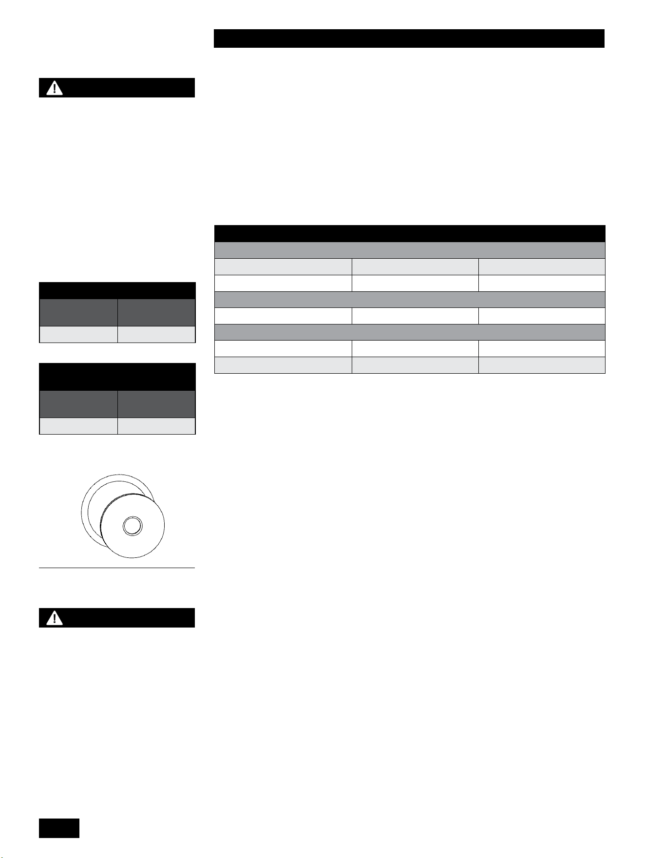
INSTALLATION AND OPERATION INSTRUCTIONS
3-4
TANKLESS WATER HEATER 199
INSTALLATION AND OPERATION INSTRUCTIONS
3-4
TANKLESS WATER HEATER 199
3.4 FUEL CONVERSION
Theunitisfactoryre-testedtooperate with natural gas as shown on the rating
plate. Firing a unit with a fuel other than what is listed on the rating plate is
prohibitedunlessthefollowingconversionprocedureiscompletedbyaqualied
technician.
Fuelconversionrequireshardwareadjustments(oricereplacement)aswellas
measurementandpossibletuningofthelowremixture.Detailedinstructions
including parts and labeling are found in Fuel Conversion kits. Refer to Table 10
for the correct kit number.
NATURAL GAS PROPANE
CO
2
VALUE
(
%
)
AT HIGH FIRE WITH THE FRONT COVER OPEN¹
Max. CO
2
value 10.3% 11.0%
Min. CO
2
value 8.7% 9.8%
CO LIMIT
(
PPM
)
AT HIGH FIRE WITH THE FRONT COVER OPEN²
Max. CO limit < 150ppm <250ppm
CO
2
VALUE
(
%
)
AT LOW FIRE WITH THE FRONT COVER OPEN
Max. CO
2
value =valueatHigh =valueatHigh–0.3%
Min. CO
2
value 8.7% 9.5%
Table 11: Acceptable High and Low Fire Combustion Values
¹HighFireCO2issetbytheoriceinstalledandisnoteldadjustable.
² If the CO reading exceeds the limit in this table, the unit must be shut down until the
cause of excessive CO readings is corrected.
Thefollowingproceduremustbecarriedoutbyaqualiedtechnician.
1. Ensurethatthegassupplyisturnedoatthemanualgasvalve.
2. Disconnect the electrical power.
3. Disconnect the nut at the gas valve outlet (top of the gas valve) and remove
theoriceandO-ring.
4. InsertthecorrectoriceintotheO-ring,andre-installintothenutatthegas
valve outlet (top of the gas valve) and then tighten the nut.
5. Restore the gas supply by opening the manual gas valve.
6. Testforleaksbyusinganapprovedleakdetectionsolutiononalljoints.
7. Carefully follow the “Prior to Start-Up” – Section 3.2 and “Commissioning” –
Section 3.3 procedures on the preceeding page 3-2.
DANGER
Operating any unit using
a fuel other than the fuel
listed on its rating plate is
prohibited. If the information
in this section related to
conversion to alternative
fuels is not followed exactly,
a dangerous situation can
result, leading to re or
explosion, which may cause
property damage, personal
injury, or loss of life.
Figure 33: Orice and O-ring
PROPANE ORIFICE CHART
MODEL
ORIFICE
SIZE
199,000 Btu/hr 535
NATURAL GAS ORIFICE
CHART
MODEL
ORIFICE
SIZE
199,000 Btu/hr 660
WARNING
Ensure the part kit and
orice are correct for the
appliance model and fuel type
prior to performing the fuel
conversion.
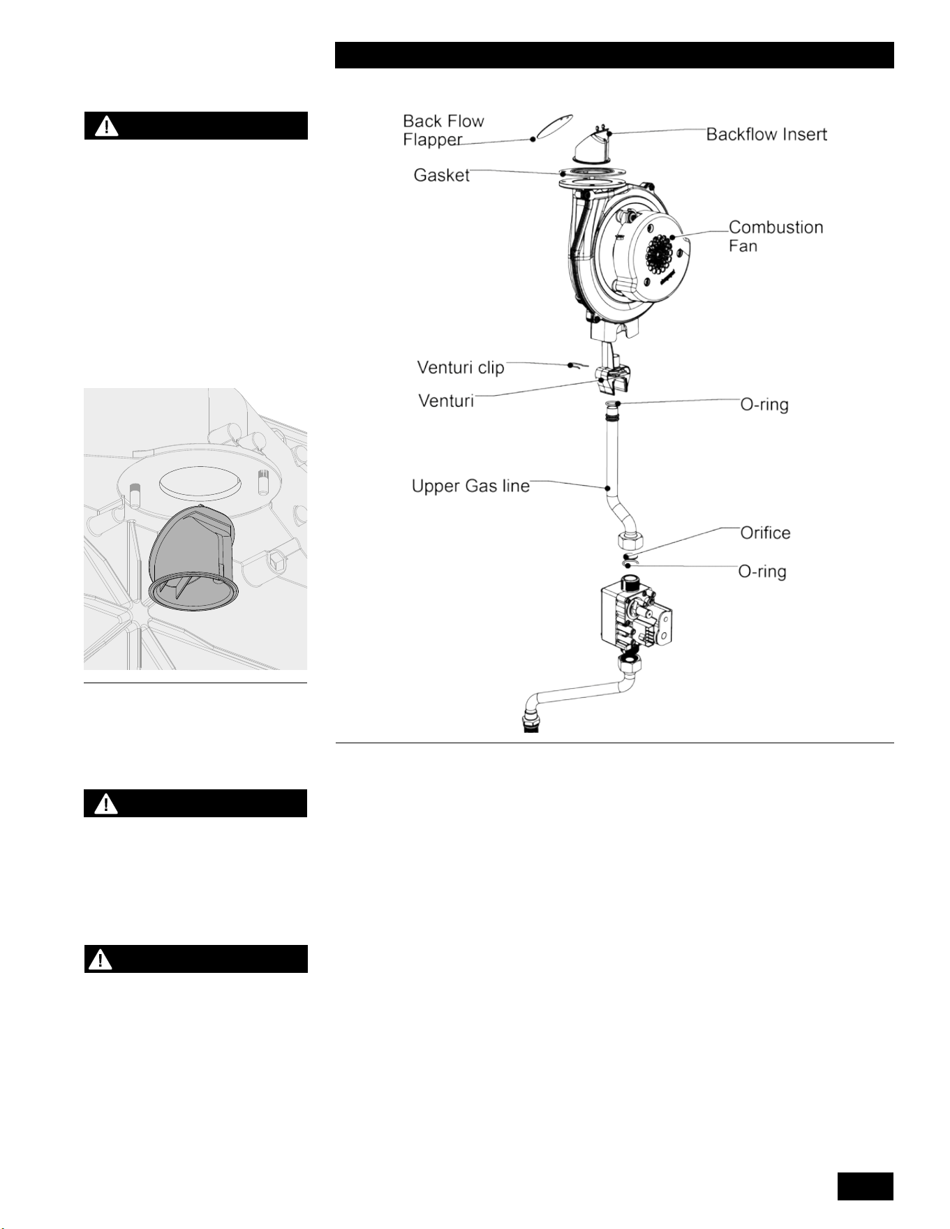
3-5
STARTUP AND COMMISSIONING
TANKLESS WATER HEATER 199
Figure 34: Back Flow Valve
Figure 35: Blower and Gas Valve Assembly
WARNING
Each unit is equipped with
a back ow valve installed
at the outlet of the fan.
Inspect the back ow apper
annually.
3.4.1 Gaining access to combustion chamber, burner
removal instructions
DISASSEMBLY
1. Turnothemainpowerswitchtotheunit.
2. Turnothegassupplyvalvetotheunit.
There is no need to drain the unit unless the unit will be exposed to freezing
conditionswhileo.
3. Remove the front cover, and allow the unit to cool.
4. Unplug the electrical connector at the gas valve and fan.
5. Loosen the lower gas valve connection nut.
NOTE: There is an O-ring in the lower gas connection. Cover the gas piping
connections to prevent debris from entering the gas piping.
6. Remove all 6mm Allen bolts and lock washers from the heat exchanger
cover and carefully remove the front cover complete with the fan and the gas
valve attached.
7. Place the heat exchanger cover in a safe location.
NOTE
The Caution reguarding
burner refractory on page
4-2 of this manual must be
observed.
CAUTION
When removing the heat
exchanger cover in step 6,
be careful not to damage the
burner and refractory material
located on the opposite side
of the heat exchanger cover.
Use caution when handling
refractory materials. See
Caution on page 4-2.
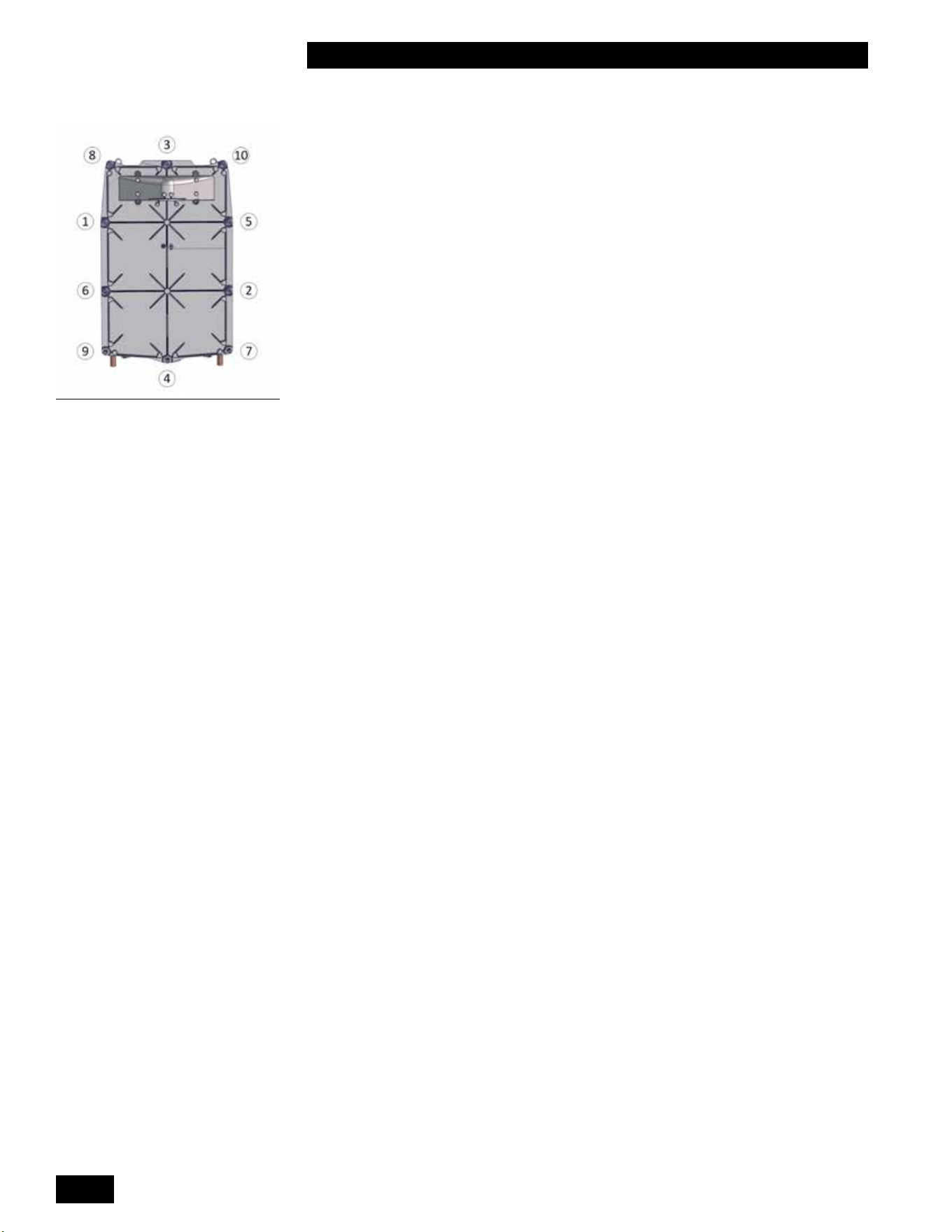
INSTALLATION AND OPERATION INSTRUCTIONS
3-6
TANKLESS WATER HEATER 199
INSTALLATION AND OPERATION INSTRUCTIONS
3-6
TANKLESS WATER HEATER 199
REASSEMBLY
1.
Replace the heat exchanger gasket. Inspect, and when needed change
other gaskets. If necessary, inspect and clean the gasket mating surface.
2. Place the heat exchanger cover onto the heat exchanger and loosely install
the 6mm Allen bolts and lock washers removed in step 6. Tighten the 6mm
Allen bolts in a cross pattern as shown in the Figure 36.
3. Connect the gas line to the gas valve ensuring the O-ring is in place. Tighten
the gas valve nut. Ensure the upper gas valve connection is tight. Re-connect
the gas valve electrical connection.
4. Re-connect the electrical connection to the fan.
5. Inspect the condensate trap for debris. Remove and clean if necessary. Fill
the condensate trap with water.
6. Turn on the gas supply valve to the unit and inspect for gas leaks. Use an
approvedleakdetectionsolution.Soaptestalljoints.
7. Ensure the unit is full of water and purged of air if the unit was drained during
disassembly.
8. Turn on the power to the unit and create a call for domestic hot water.
9. Inspect the gasket around the unit cover.
10. Checkuegasesforpropercombustion.See Section 3.3 Commissioning for
properadjustments.
11. Re-installtheunit’scoverandsettheunitintonormaloperation.
Figure 36: Tighten hex bolts in
cross pattern direction.
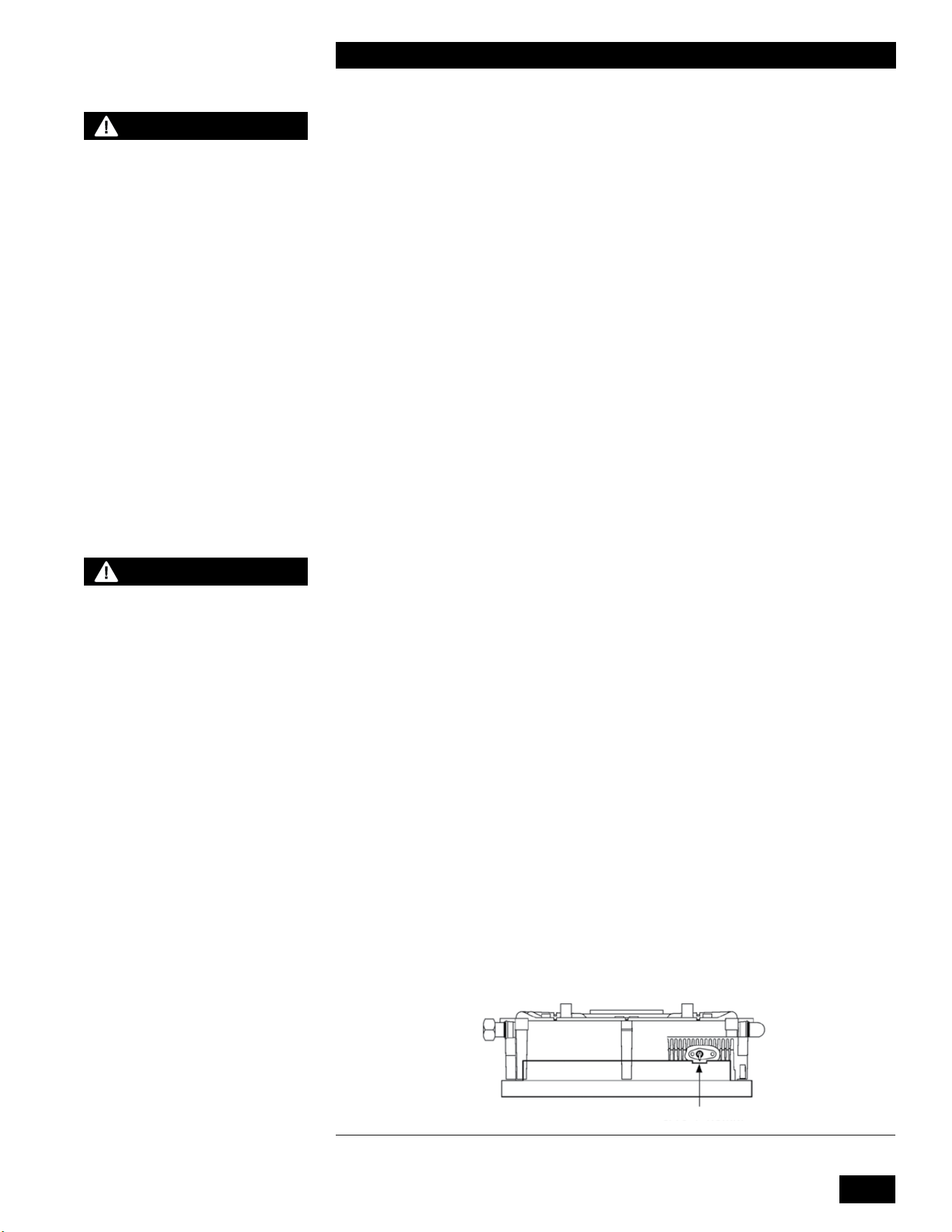
4-1
MAINTENANCE
TANKLESS WATER HEATER 199
4.0 MAINTENANCE
4.1 WATER HEATER MAINTENANCE
4.1.1 General Care
•
Keepcombustiblematerialsandammableliquidsandvaporsawayfromtheunit.
• Keep vent terminals clear of obstructions (snow, dirt, etc.).
4.1.2 Inspection
•
Inspectionoftheunitmustbeperformedannuallybyaqualiedservice
technician.
4.1.3 Venting
•
Check vent terminals for any obstructions (e.g. leaves, dust, other debris).
• Checkandcleanorreplaceintakeairltersorscreensasrequired.
• Check for holes or leaks in venting. Replace venting as needed.
• Examine for any signs of moisture caused by sweating intake air pipes.
Insulateasrequired.
• Ensure proper resealing or reinstallation of venting at each servicing.
4.1.4 Condensate Trap
•
Examine the condensate trap every two months to see if cleaning is
necessary (refer to trap cleaning instructions, section 4.1.15 of this manual).
Ensurethatthetraphasbeenre-lledcompletelybeforeringtheunit.
• Check the pH level of the condensate discharge if using condensate
neutralization.
4.1.5 Burner
•
Attherstannualservice,removetheburnertoinspecttheextentoffouling
(refer to burner removal and reassembly instructions, section 3.4.1 of this
manual). Blow clear using compressed air. Evaluate the magnitude of
cleaningrequired,andestablishareasonableburnerinspectionschedule.
Some installations may call for annual service, others showing clean burners
willonlyneedattentionevery2years.Consideraddingairltrationifthe
burnerrequirescleaningeveryyear.Inalternateyears,visuallyinspectburner
throughthesightglass.Ensuretheameisstableandwithoutexcessive
uttering.Normalamepatternisevenlydistributedovertheburnersurface.
• If the burner is operating improperly, remove and clean or replace. Use a
combustion analyzer to determine proper combustion. See Table 11 for
correct values.
3/16" / 4.5MM
Figure 37: Checking igniter gap using 251-001 Ignitor Gapping Tool
CAUTION
- The owner is responsible
for general care of the unit.
Improper maintenance of the
unit may result in a hazardous
condition.
- When servicing controls,
label all wires prior to
disconnection. Wiring errors
can cause improper and
dangerous operation.
- When removing a burner,
a new burner gasket is
required.
WARNING
- Fill the trap with water
before the unit is rst red to
prevent exhaust fumes from
entering the room. Never
operate the unit unless the
trap is lled with water.
Failure to comply will result in
severe personal injury or death.
-
Whenever the burner is
removed for inspection
or servicing, examine the
sealing gaskets and replace if
damaged.

INSTALLATION AND OPERATION INSTRUCTIONS
4-2
TANKLESS WATER HEATER 199
4.1.6 Heat Exchanger
During annual inspection (with the heat exchanger cover removed), examine
the heat exchanger for signs of contamination and clean if necessary. In areas
ofpoorgasqualityorcontaminatedcombustionair,theremaybeabuild-upof
blackplaque(typicallysulfur).Otherfoulingagentsareairbornedust,debrisand
volatiles.Cleantheheatexchangersurfacewithastiplasticbristlebrushonly.
During maintenance, the heat exchanger gasket must be replaced. Inspect other
gaskets, and change when needed. Refer to the heat exchanger cover removal
instructions in Section 3.4.1 for access to the combustion chamber and heat
exchanger. Observe the safety warning regarding the burner refractory on
this page.
4.1.7 Gas Piping
Check for damage or leaks, and repair as needed.
4.1.8 Control Module
•
Check that unit operation is consistent with the steps in Section 2.5
Sequence of Operation.
• Check that water temperature target is satisfactory, and that it has not been
adverselyadjusted.
4.1.9 Freeze Protection
The controller ignites the burner as needed to protect the unit from freezing.The controller ignites the burner as needed to protect the unit from freezing.
4.1.10 Relief Valve - Maintenance and Testing
Reliefvalvemanufacturersrequirethatundernormaloperatingconditionsa“try
levertest”mustbeperformedquarterly.Undersevereserviceconditions,orif
corrosion and/or deposits are noticed within the valve body, you must test more
often. Also perform a “try lever test” at the end of any non-service period.
Test at or near maximum operating pressure by holding the test lever fully open
foratleast5secondstoushthevalveseatfreeofsedimentanddebris.Then
release the lever and permit the valve to snap shut.
If the lever does not activate, or there is no evidence of discharge, discontinue
useofequipmentimmediately,andcontactalicensedcontractororqualied
service personnel.
Ifthereliefvalvedoesnotcompletelyseal,anduidcontinuestoleakfrom
thedischargepipe,performthetestagaintotryandushanydebristhatmay
be lodged in the valve. If repeated attempts fail to stop the leakage, contact a
licensedcontractororqualiedservicepersonneltoreplacethevalve.
4.1.11 Domestic Hot Water System
Verify that domestic hot water generation is performing as expected and that
waterqualityiswithintheguidelinesshowninTable12.Cleantheinternal
DHWcoilusingnontoxictanklesswaterheatercleaningsolutionasrequired
tomaintainpeakDHWoperationandeciency.FoulingoftheDHWcoilwill
CAUTION
The heat exchanger has a small
amount of combustion chamber
insulation (refractory) that
contains ceramic bers.
When exposed to extremely
high temperatures, the ceramic
bers, which contain crystalline
silica, can be converted into
cristobalite, classied as a
possible human carcinogen.
Avoid disturbing or damaging
the refractory. If damage occurs,
contact the factory for directions.
Avoid breathing in fumes and
contact with skin and eyes.
Follow these precautions:
1. For conditions of frequent
use or heavy exposure,
you need a respirator. For
respirators certied by
NIOSH, refer to the “NIOSH
Guide to the Selection
and Use of Particulate
Respirators Certied under
42 CFR 84”.
For current information,
contact NIOSH on 1-800-356-
4676 or on the web at
www.cdc.gov/niosh.
2. Wear long sleeved, loose
tting clothing, gloves and
eyes protection.
3. Assure adequate ventilation.
4. Wash with soap and water
after contact.
5. Wash potentially
contaminated clothes
separately from other
laundry, and rinse clothes
thoroughly.
6. Discard used insulation in an
air tight plastic bag.
NIOSH rst aid guidelines:
• Eye contact - Irrigate and
wash immediately.
• Breathing in fumes - Provide
fresh air.
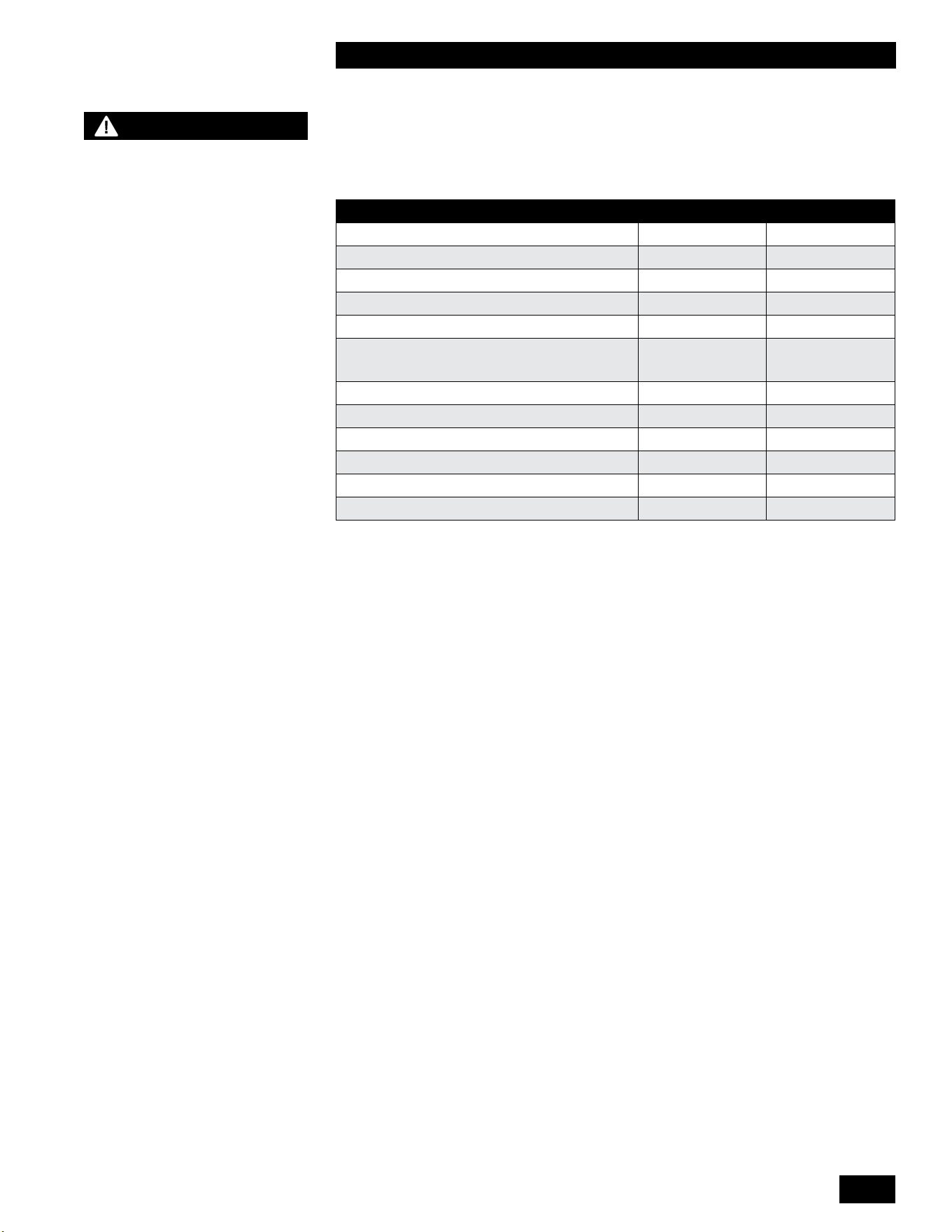
4-3
MAINTENANCE
TANKLESS WATER HEATER 199
accelerateandrequiremorefrequentcleaningwithincreasedwaterhardness.
Installation of a water softener at sites with hard water is recommended to reduce
foulingandcleaningfrequency.Failurescausedbylime,mineralbuildup,or
scale due to a lack of maintenance will not be covered under warranty.
DESCRIPTION MAX MIN
Water Pressure 150 PSI 40 PSI
Programmable Water Temperature 149°F (65°C) 105°F (40°C)
Minimum DHW Flow Rate to Initiate Operation N/A 0.5 GPM
pH 8.5 6.5
Total Dissolved Solids (TDS) 500 mg/L
Total Hardness 250 mg/L
14.6 grains/gal
Aluminum 0.2 mg/L 0.05 mg/L
Chlorides 250 mg/L
Copper 1 mg/L
Iron 0.3 mg/L
Manganese 0.05 mg/L
Zinc 5 mg/L
Table 12: Domestic Water Quality Guidelines
4.1.12 DHW Coil cleaning instructions
Clean the DHW coil as follows:
1. These instructions assume that a set of service valves have previously been
installed.
2. Theseinstructionsassumetheuseofatanklesswaterheaterushkit.
3. Turnotheunitbytouchingtheareaabovethedotfor2seconds.
4. Openahotwaterfaucetuntiltheheatexchangerissucientlycool.
5. Close the gas valve and DHW hot and cold water isolation valves.
6. Attach two hoses to the DHW hot and cold water service valve hose
connections.
7. Attachthecoldwaterhosetotheushkitpumpandplaceina5gallon
bucket.
8. Place the loose end of the hot water hose in the bottom of the 5 gallon
bucket and open the DHW hot and cold water service valves.
9. Pour 2 gallons of nontoxic tankless water heater cleaning solution in the
bucket.
10. Plug in the pump and allow the cleaning solution to circulate in accordance
withthemanufacturer’sinstructions.
11. AftercleaningtheDHWcoil,disconnectthewireharnessfromtheuegas
temperaturesensoronmodelsequippedwithaninternaldomestichotwater
bypass valve. The lockout will cause the internal domestic hot water bypass
valve to send cleaning solution through the bypass line.
12. Allowthecleaningsolutiontocirculateinaccordancewiththemanufacturer’s
instructions.
13. After cleaning the bypass line, unplug the pump and close the DHW cold
water service valve.
14. Remove the hot water hose from the 5 gallon bucket and route to a suitable
drain.
CAUTION
Before testing the relief valve,
make certain the discharge
pipe is properly connected to
the valve outlet, and arranged
to contain and safely dispose
of equipment discharge.

INSTALLATION AND OPERATION INSTRUCTIONS
4-4
TANKLESS WATER HEATER 199
15. OpentheDHWcoldwaterisolationvalveandushoutthebypasslinefor
about 5 minutes.
16. Reconnectthewireharnesstotheuegastemperaturesensorandresetthe
lockout by pressing the wrench for 2 seconds.
17. Flush out the DHW coil for about 5 minutes then close the DHW hot water
service valve and open the DHW hot water isolation valve.
18. Disconnect the two hoses from the DHW hot and cold water service valve
hose connections.
19. Open the gas valve and turn on the unit by touching the area above the dot
for 2 seconds to resume normal operation.
4.1.13 DHW Filter cleaning instructions
CleantheDHWwaterlterduringannualmaintenanceasfollows:
1. Turnotheunitanddisconnectpower.
2. TurnotheDHWhotandcoldisolationvalves.
3. Place a bucket under the drain and drain the DHW water from the unit.
4. Unscrewthewaterlterfromtheunit’scoldwaterinlet.
5. Cleanthewaterlterunderrunningwater.Useasoftbrushifnecessary.
6. Reinstallthewaterlterintheunit’scoldwaterinlet.
7. Open the DHW hot and cold isolation valves.
8. Reconnect the power and return the unit to operation.
4.1.14 Fan removal instructions
1. Turnothepowerandthegassupplytotheunit.
2. Remove the front cover, and allow the unit to cool down.
3. Disconnect the electrical plug attached to the fan.
4. Loosentheunionnutatthetopofthegasvalve.Carefullyremovetheorice
and O-ring, and keep in a safe place for re-installation later. Ensure you
protect the gas valve outlet from dust and debris.
5.
Remove the 2 hex nuts connecting the fan to the burner housing, and
carefullyremovethefan.Youwillndagasketattachedtothefanoutletas
well as an internal check valve. Keep these items in a safe place for re-
installation.
6. If the removed fan is to be re-installed, ensure the fan and venturi are clean
and dust free. If the fan is being replaced, move the venturi over to the new
fan.Notethatthetistight.
4.1.15 Fan installation instructions
1. Place the fan gasket on the outlet of the fan housing. The gasket has 2
locator pins to ensure the gasket does not move during installation.
2. Reinstall the check valve in the burner housing and attach the fan to the
burner housing with the 2 hex nuts. Tighten the 2 hex nuts with a wrench.
3. InserttheoriceandO-ringbetweenthegasvalveoutletandthegaslineto
the fan. Tighten the gas valve union nut with a wrench. Ensure that the gas
valve inlet (lower) nut is tight.
4. Connect the electrical plug to the fan.
5. Restore the gas supply to the unit, and test the gas valve inlet for gas leaks.
DANGER
When servicing or replacing
the fan, you must transfer the
venturi from the old fan to the
new fan.
Failure to relocate the venturi
to the new fan may cause
an immediately hazardous
situation which must be
avoided in order to prevent
serious injury or death.
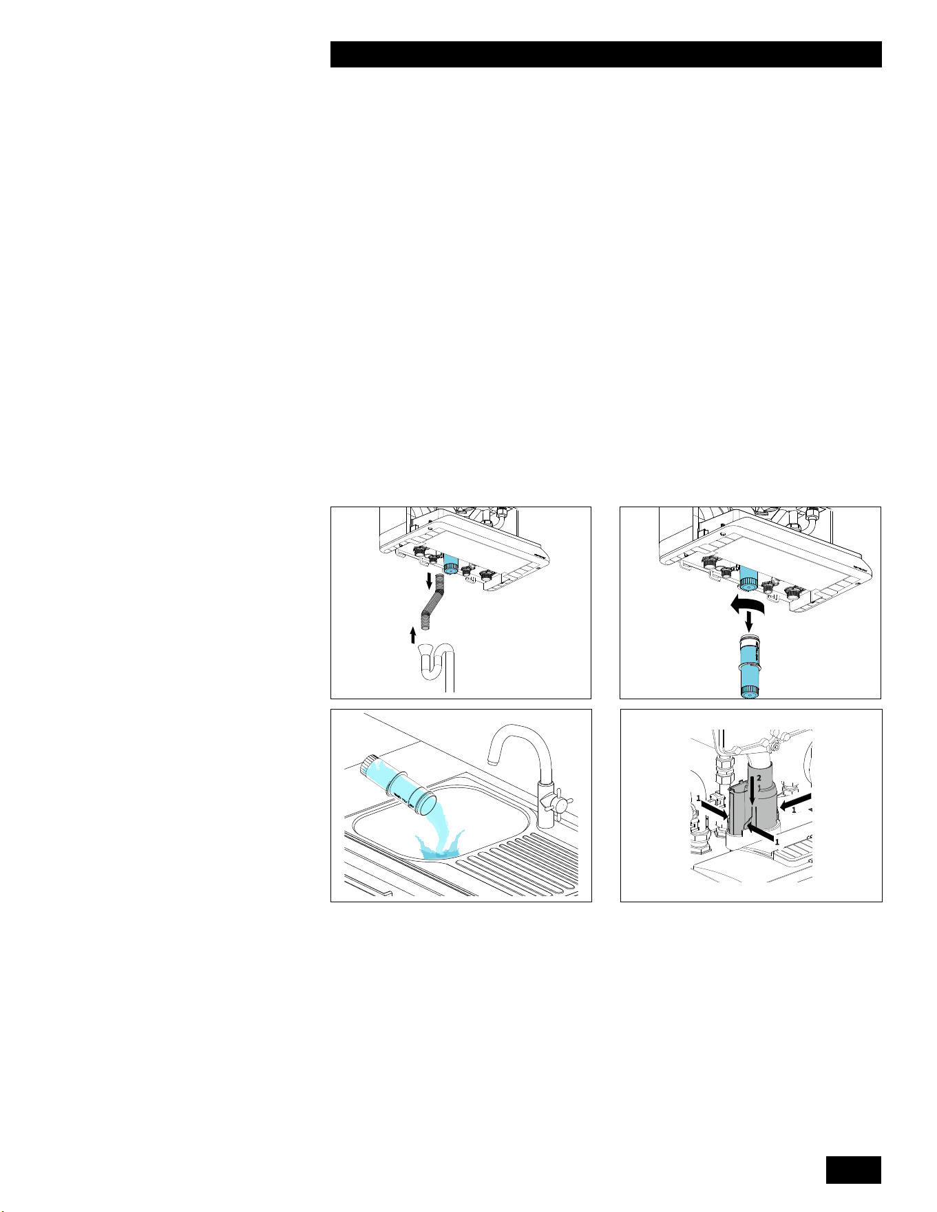
4-5
MAINTENANCE
TANKLESS WATER HEATER 199
6. Restore the power to the unit, and create a call for hot water.
7. Check for leaks at the gas valve outlet and the connection between the fan
and the burner housing.
8. Install the cover to the unit.
9. Return the unit to normal operation.
4.1.16 Cleaning the Condensate Trap
1. Turnothepowerandthegassupplytotheunit.
2. Remove the front cover, and allow the unit to cool down.
3. Removetheexiblehose(1)fromthecondensatetrapanddrain.
4. Detach the condensate trap cup (2) by rotating it to the left (counter-
clockwise) and then pulling it downwards.
5. Empty the condensate trap cup (3).
6. Detach the condensate trap base (4) by pressing the three securing clips in,
while simultaneously pushing the condensate trap base downwards (4).
7. Remove the circlip and the plastic ball from the condensate trap base (5)
8. Clean the following components with water:
● the inside of condensate trap base
● plastic ball
● circlip
● condensate trap cup
● openingoftheuepipe
1 2
3
1
1
1
2
4
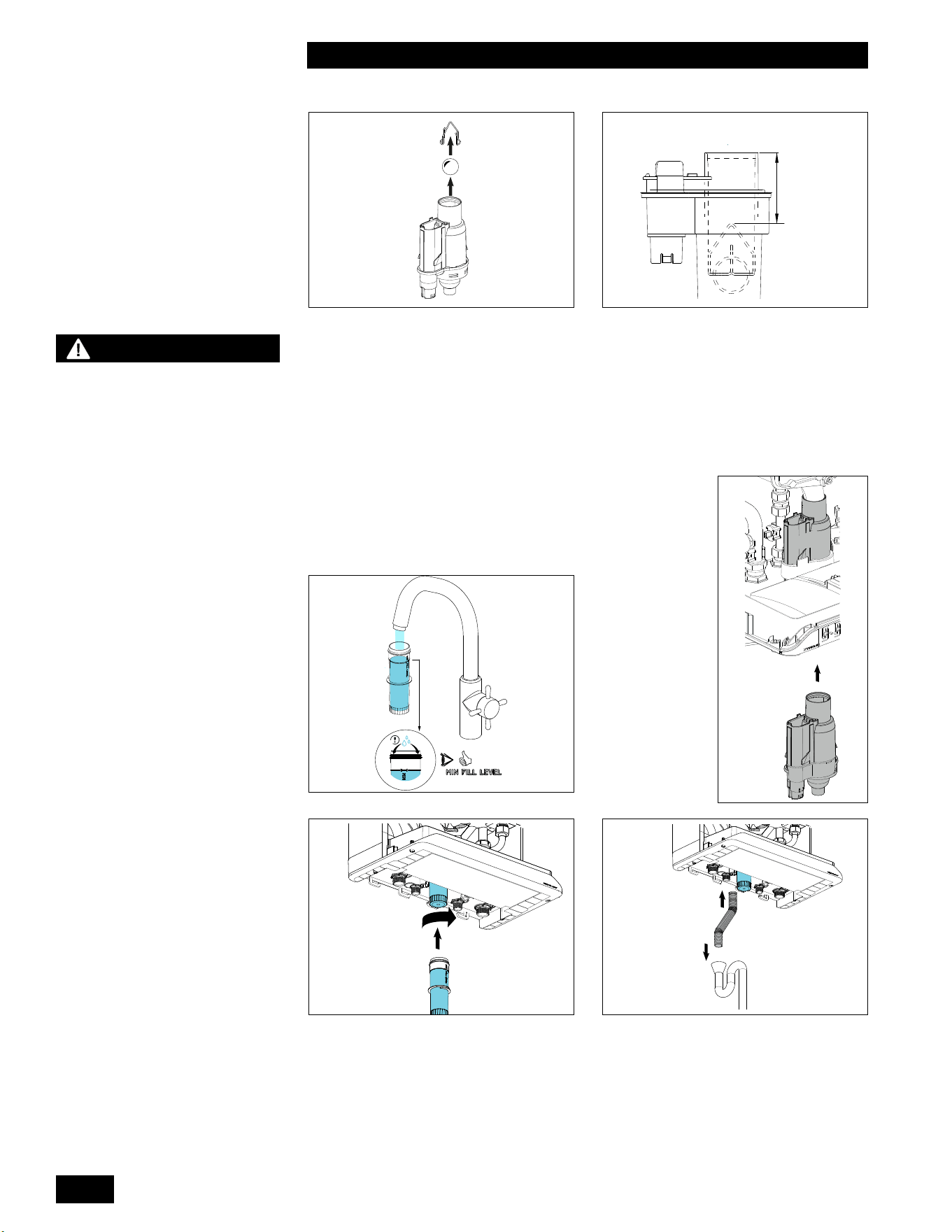
INSTALLATION AND OPERATION INSTRUCTIONS
4-6
TANKLESS WATER HEATER 199
9. Return the plastic ball to the condensate trap base and attach the circlip.
10. Check that the ball and circlip have been installed correctly (6). Make sure
that the top of the circlip is about 2 1/4” (60 mm) below the edge of the
condensate trap base.
11. ReplacetheO-ring(part#150-367)atthebottomoftheuepipe.
12. Attach the condensate trap base to the bottom by pushing it high enough so
that the securing clips click over the lip (8).
5
2 ¼"
(60 mm)
6
13. Makesurethecondensatetrapcupis¾lled
with water (7) before installation, slide it into the
condensate trap base and rotate it to the right
(clockwise) until it is correctly secured (9).
7
–
C
L
I
C
K
!
–
8
9 10
14. Slidetheexiblehoseontothecondensatetrapbaseandintothedrain(10)
DANGER
Make sure that the
condensate trap base is
returned to its original
position, rmly locked into
the bottom with no gaps.
Incorrectly attaching the
condensate trap base (or not
attaching it at all) will result
in products of combustion
leaking into the room creating
a dangerous situation.

4-7
MAINTENANCE
TANKLESS WATER HEATER 199
CAUTION
The maintenance counter
must only be reset after
performing the maintenance
procedures in Section
4.0 Maintenance of this
manual. Failure to perform
maintenance can result in a
hazardous condition.
4.1.17 Reset the Maintenance Counter
The maintenance counter should be reset after all maintenance items in this
section have been completed. Refer to Resetting the Maintenance Counter,
section 2.7 of this manual.
NOTE
Damage to the Tankless Water
Heater caused by freezing
water is not covered by the
warranty.
4.1.18 Winterization
The Tankless Water Heater must be winterized along with the rest of the
domestic water system when the system will be shut down for an extended
periodoftimeandbesubjecttofreezingconditions.
1. Turnothepowerandthegassupplytotheunit.
2. Drain the units domestic hot water coil along with the rest of the domestic
water system.
3. Remove the condensate trap cup and empty.
4. If present, empty condensate pump.

INSTALLATION AND OPERATION INSTRUCTIONS
4-8
TANKLESS WATER HEATER 199
This page is intentionally left blank.

5-1
TROUBLESHOOTING
TANKLESS WATER HEATER 199
5.0 TROUBLESHOOTING
The troubleshooting section is divided into four sections:
5.1 Preliminary Checks
5.2 Electronic Components
5.3 Faults and Notications
5.4 Other Faults
Often, you can identify and solve a problem through simple checks of the basics:
conrmingtheelectricalpowersupplyandgasow.Tohelpwithpreliminary
checks,theunit’scontrolmoduleoersavisualdisplayofthestatusofthevarious
control circuit components.
Should a problem remain unsolved after applying the preliminary checks,
proceed to the detailed system review in this guide. The Troubleshooting chapter
covers potential error conditions, grouped into the following categories:
5.3.1 Fault Codes
5.3.2 Notication Codes
5.4.1 No domestic hot water (DHW)
5.4.2 Domestic hot water does not reach the correct temperature
5.4.3 Burner ignites loudly
5.4.4 Burner resonates
Below each section is a list of symptoms, diagnoses, and solutions.
Some diagrams (see Section 6.0) are included for use with troubleshooting
including:
• Electrical wiring diagrams
• Water heater component layout diagrams
5.1 PRELIMINARY CHECKS
Asarststepintroubleshooting,youshouldreviewthecontroller’sdisplay
screen. Diagnostic features evaluate system integrity, display error conditions,
and indicate initial troubleshooting action.
Inadditiontocheckingthecontroller’sdisplay,trythesetroubleshootingsteps:
1. Conrmpowertotheunit:checkthatcontrolmoduledisplayison(e.g.,
display is lit).
2. Check that unit is not in a safety lockout.
3. Ensure that wiring is secure and properly terminated.
4. Check that gas is reaching the unit.
5.
Conrmthatthedomesticwatersystempressureisaminimum40psig.
NOTE
This appliance is equipped
with a blocked vent shut-o
system that closes the gas
supply when it detects an
irregular venting condition.
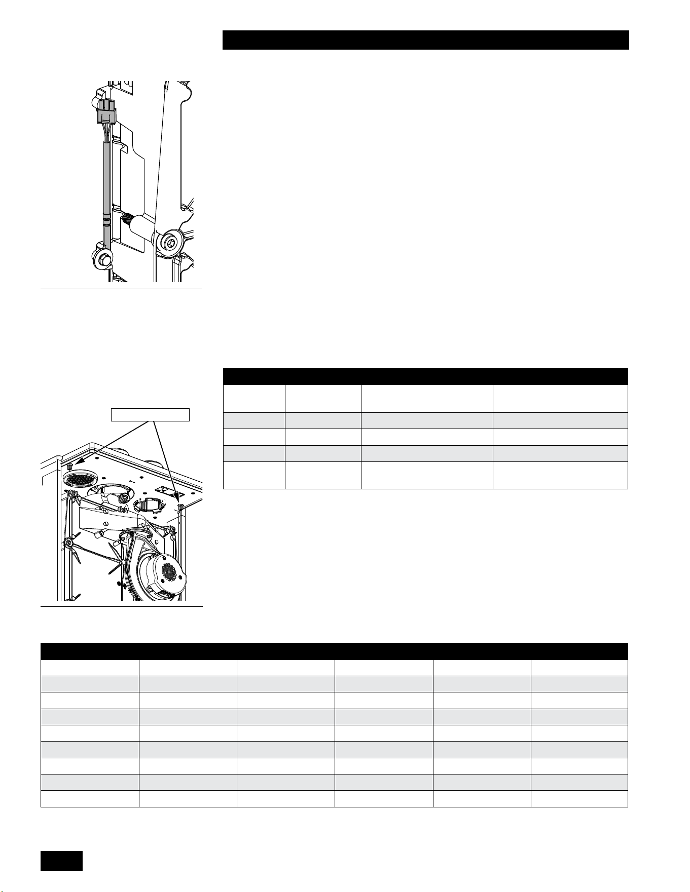
INSTALLATION AND OPERATION INSTRUCTIONS
5-2
TANKLESS WATER HEATER 199
5.2 ELECTRONIC COMPONENTS
This section details the method for troubleshooting the non-standard electronic
components on the unit.
5.2.1 Temperature Sensors
The resistance of the temperature sensors varies inversely with temperature. To
test, measure the temperature of the sensed environment and compare with the
value derived from the measurement of the resistance (obtained by connecting a
goodqualitytestmetercapableofmeasuringupto5,000KΩ(5,000,000Ω)atthe
controller end of the sensor lead).
To obtain a resistance reading, remove power to the unit. For the water sensors,
remove the wire leads by disconnecting their respective Molex connectors. Place
multi-meterprobesintothesensor’smaleMolexconnectorsocket.Donotapply
voltage to the sensor as damage may result.
12KΩ temperature sensors are supplied with the unit. See Table 14 for resistance
values.
SENSOR TYPE PURPOSE LOCATION
S0
NTC12KΩ
Heat Exchanger
Temperature
Left side of Heat Exchanger
S3 NTC12KΩ Domestic Hot Water DHW Supply Pipe
S4 NTC12KΩ Domestic Cold Water DCW Supply Pipe
S5 NTC12KΩ Flue Gas Temperature Top of rear Flue passage
PTC1
PTC2
PTC Cabinet Temperature
Left and right Side top of
inner cabinet
Table 13: Temperature Sensors
5.2.2 Cabinet Sensors
The Cabinet temperature sensors ensure that the unit shuts down if the
temperature inside the cabinet is above normal.
The Cabinet temperature sensors are located on the left and right side at the top
of the cabinet. To remove the sensors, unclip the wiring harness and unscrew
from the top cabinet.
TEMPERATURE RESISTANCE TEMPERATURE RESISTANCE TEMPERATURE RESISTANCE
F / C Ω-ohm F / C Ω-ohm F / C Ω-ohm
5F / -15C 76,020 77F / 25C 12,000 149F / 65C 2,752
14F / -10C 58,880 86F / 30C 9,805 158F / 70C 2,337
23F / -5C 45,950 95F / 35C 8,055 167F / 75C 1,994
32F / 0C 36,130 104F / 40C 6,653 176F / 80C 1,707
41F / 5C 28,600 113F / 45C 5,522 185F / 85C 1,467
50F / 10C 22,800 122F / 50C 4,609 194F / 90C 1,266
59F / 15C 18,300 131F / 55C 3,863 203F / 95C 1,096
68F / 20C 14,770 140F / 60C 3,253 212F / 100C 952
Table 14: Temperature Sensor Resistance Values – 12KΩ sensors.
Figure 38: Heat exchanger
Temperature Sensor S0
Cabinet sensors
Figure 39: PTC Cabinet
Temperature Sensors
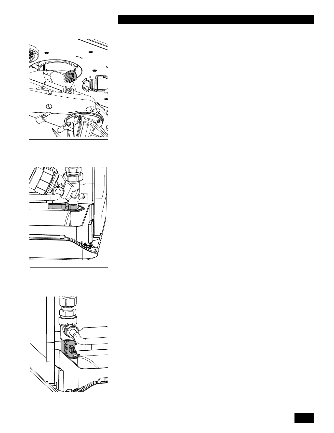
5-3
TROUBLESHOOTING
TANKLESS WATER HEATER 199
Figure 42: Domestic Hot Water
Temperature Sensor S3
5.2.3 Flue Gas Temperature Sensor
Thissensorensuresthattheunitshutsdownsafelyiftheuetemperature
isabovenormal.Highuetemperaturescanbeanindicationthattheheat
exchangerrequirescleaning.
Theuegastemperaturesensorislocatedatthetopoftherearuepassage,
below the top panel. To remove the sensor, unclip from the wiring harness and
unscrewfromtherearuepassage.
5.2.4 Domestic Hot Water Flow Sensor
Theunitisequippedwithaowsensortomeasurewaterowthroughthe
domestichotwatercircuitinthewaterheater.Theowsensorconsistsoftwo
parts, the mechanical turbine in the cold water inlet and the external inductive
sensorsurfacemountedontheoutsideofthecoldwaterinlet.Theminimumow
requiredtoactivatethewaterheateris0.5GPMor2L/min.
To service or replace the mechanical turbine:
1. Disconnect power to the unit.
2.
Turnothecoldandhotwatervalvesbelowtheunit,releasethewater
pressure and then drain the domestic hot water circuit. Leave the drain valves
open.
5.2.5 Domestic Hot Water Sensor
Theunitisequippedwithadomestichotwatertemperaturesensor.Thesensoris
surface mounted on the hot water outlet pipe.
Figure 40: Flue gas Temperature
Sensor S5
Figure 41: Domestic Water Flow
Sensor
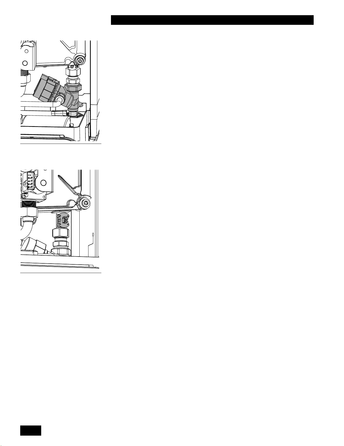
INSTALLATION AND OPERATION INSTRUCTIONS
5-4
TANKLESS WATER HEATER 199
5.2.6 Domestic Hot Water Bypass Valve
Thisunitisequippedwithadomestichotwaterbypassvalvewhichallows
cold water to bypass the heat exchanger to temper the domestic hot water
temperature.
1. To service or replace the bypass valve:
2. Turnotheunitanddisconnectpower.
3. Close the DHW hot and cold isolation valves.
4. Place a bucket under the drain and drain the DHW water from the unit.
5. Disconnect and remove the bypass tube.
6. RemovetheretainingclipundertheunitattheDHWlter.
7. Disconnect the bypass valve from the heat exchanger using two wrenches.
5.2.7 Domestic Cold Water Sensor
TheCombiboilerisequippedwithadomesticColdwatertemperaturesensor.The
sensor is surface-mounted on the Cold water inlet pipe.
5.2.8 Fan/Blower
Control and power to the fan is provided via a single wiring harness to the
controller.
Figure 43: Bypass Valve
Figure 44: Domestic Cold Water
Temperature Sensor S4

5-5
TROUBLESHOOTING
TANKLESS WATER HEATER 199
5.3 FAULTS AND NOTIFICATIONS
5.3.1 Fault Codes
During operation the controller can detect unusual situations and can take action to avoid damage to the heat
exchanger or other unsafe operations. During these situations, the controller limits the temperature and power output
of the burner, or temporarily disables operation entirely.
Thesewarningsareshownashingandvisibleonthemaindisplay,anddisplayedonlywhenanunusualreadingis
currently detected. Fault Codes can be reset by touching the wrench for 2 seconds after the cause of the fault has
been resolved.
FAULT CODE DESCRIPTION POSSIBLE CAUSE / SOLUTION
F000 Heat exchanger temperature sensor
fault.
• Verify wire harness connections at heat exchanger
temperature sensor and control module are tight.
• Replace heat exchanger temperature sensor.
F002 High heat exchanger temperature during
DHW demand.
• Verify the unit has been converted to propane if
operating on propane
• Verifycombustionreadingsatlowandhighreare
withinspecications.
• Clean heat exchanger DHW coil.
• Cleanresideofheatexchanger.
F003 Highuetemperature.
• Verify the unit has been converted to propane if
operating on propane.
• Verifycombustionreadingsatlowandhighreare
withinspecications.
• Cleanresideofheatexchanger.
• Clean heat exchanger central heating and DHW coils.
F004 Noamedetectedduringfourignition
trials.
• Verifyexternalgasshutovalveisopen.
• Verify gas inlet pressure is at least 4” during igntion
trial.
• Verify condensate drain is not blocked.
• Check vent and combustion air piping for blockage.
• Verify internal and power supply grounding.
• Verify ground spring is in contact with burner head
screw.
• Verify ignitor to ignition module connection is tight.
• Check ignitor condition and clean/replace as
necessary.
• Verifyoperationofthebackowapperinthefan
outlet.
• Verify ignitor is not in contact with burner and gap is
correct.
• Replaceignitionmoduleifunitlightsbutameicon
doesn’tilluminate.
• Replace ignition module if spark is not present and
110VAC is present on ignition module black and gray
wires.
• Replace control module if spark is not present and
110VAC is not present on ignition module black and
gray wires.
• Replace gas valve if gas inlet pressure does not drop
during trial for ignition and 24VDC is present at gas
valve harness.
• Replace control module if gas inlet pressure does not
drop during trial for ignition and 24 VDC is not present
at gas valve harness.

INSTALLATION AND OPERATION INSTRUCTIONS
5-6
TANKLESS WATER HEATER 199
F005 Noamedetectedduringoperation.
• Verify condensate drain is not blocked.
• Check vent and combustion air piping for blockage.
• Checkforuegasrecirculation.
• Ifventterminationissubjecttohighwinds,
recongure/relocateasnecessary.
• Verify gas inlet pressure is at least 4” at both low and
highre.
• Verifylowandhighrecombustionreadingsarewithin
specications.
• Check ignitor condition and clean/replace as
necessary.
F006
Flamedetectedwhenburneriso.Flamedetectedwhenburneriso.
• Verify good internal and power supply grounding.
• Verifyamegoesoutatconclusionofdemand,ifnot
replace gas valve.
• Replace ignition module.
• Replace control module.
F007 Lowamesignal.
• Verify ignitor to ignition module connection is tight.
• Check ignitor condition and clean/replace as
necessary.
• Verifylowandhighrecombustionreadingsarewithin
specications.
F008 Incorrect fan speed
• Verify wire harness connections at fan and control
module are tight.
• Replace fan.
• Replace control module.
F009 Control module internal fault.
• Removealleldwiringfromunitthenresetfault.
• CheckeldwiringforvoltagebackfeedifF009fault
does not return.
• Replace control module if F009 fault code returns.
F010 Heat exchanger temperature sensor
open.
• Verify wire harness connections at heat exchanger
temperature sensor and control module are tight.
• Check resistance of each heat exchanger temperature
sensor (center pin is common), replace sensor if open
circuit is found.
• Check resistance of each heat exchanger temperature
sensor (center pin is common) at control module
harness connector, repair wire harness if open circuit
is found.
F011 Heat exchanger temperature sensor
short
.
•
Check resistance of each heat exchanger temperature
sensor (center pin is common), replace sensor if short
circuit is found.
• Check resistance of each heat exchanger temperature
sensor (center pin is common) at control module
harness connector, repair wire harness if short circuit
is found.
F012 Flue temperature sensor open.
• Verifywireharnessconnectionsatuetemperature
sensor and control module are tight.
• Checkresistanceofuetemperaturesensor,replace
sensor if open circuit is found.
• Checkresistanceofuetemperaturesensoratcontrol
module harness connector, repair wire harness if open
circuit is found.
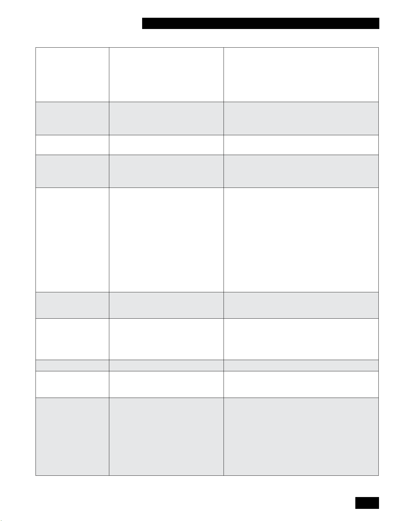
5-7
TROUBLESHOOTING
TANKLESS WATER HEATER 199
F013 DHW inlet temperature sensor open/
short
• Verify wire harness connections at DHW inlet
temperature sensor and control module are tight.
• Check resistance of DHW inlet temperature sensor,
replace sensor if open/short circuit is found
• Check resistance of DHW inlet temperature sensor at
control module harness connector, repair wire harness
if open/short circuit is found
F014 Heat exchanger temperature sensor
mounting fault.
• Heat exchanger temperature is not changing while unit
isred.
• Verify heat exchanger temperature sensor is properly
mounted on the heat exchanger.
F015 High cabinet temperature
• Checkheatexchangerforuegasleakage
• Checkventpipeforuegasleakage
F016 DHW outlet temperature sensor
mounting fault
• DHW outlet temperature is not changing while unit is
red
• Verify DHW outlet temperature sensor is properly
mounted on the DHW outlet pipe
F017 DHW bypass valve fault
• Verify wire harness connections at DHW bypass valve
and control module are tight
• Check resistance of DHW bypass valve at control
module harness connector:
Green-Purple=30to40Ω
Green-Blue=30to40Ω
Green-Yellow=30to40Ω
Green-Orange=30to40Ω
Red-Black=5.5to6.5MΩ
Red-Brown=17to21MΩ
• If any resistance value is outside of these ranges,
check and repair any wire harness open/short circuit
before replacing DHW bypass valve
F018 Flue/Combustion Air blockage.
• Check the vent and combustion air pipes for blockage.
• Verifyoperationofthebackowapperinthefan
outlet.
F019 Boiler Memory Module (BMM) fault.
• Verify wire harness connections at boiler memory
module and control module are tight.
• Verify wire harness continuity between boiler memory
module and control module .
• Replace boiler memory module.
F021 Critical parameter changed
• Factoryresetrequired
F028 Reset button fault
• Check the reset button for unintentional operation (e.g.
cleaning of the control panel).
• Replace the control module.
F029 Gas valve fault.
• Verify wire harness connections at gas valve and
control module are tight
• Replace gas valve if upper coil resistance is not 35 to
45Ω.
• Replace gas valve if lower coil resistance is not 20 to
30Ω.
• Check resistance of gas valve at control module
harness connector, repair wire harness if open/short
circuitisfoundorifresistanceisnotwithin60to70Ω
• Replace control module.

INSTALLATION AND OPERATION INSTRUCTIONS
5-8
TANKLESS WATER HEATER 199
F040 Cabinet temperature sensor open.
• Verify wire harness connections at cabinet
temperature sensors and control module are tight.
• Check resistance of cabinet temperature sensors,
replace sensor if open circuit is found.
• Check resistance of cabinet temperature sensors at
control module harness connector, repair wire harness
if open circuit is found.
F041
Cabinet temperature sensor short
•
Check resistance of cabinet temperature sensors,
replace sensor if short circuit is found.
• Check resistance of cabinet temperature sensors at
control module harness connector, repair wire harness
if short circuit is found.
F042 Cascade DHW not available
• Resolve any other lockouts in the cascade system
• Verify Leader cascade parameter settings are correct
• Verify Follower(s) cascade parameter settings are
correct
• Check cascade communication status in the
information menu of both Leader and Follower
-- (Blinking) Water presssure sensor fault
• Verify wire harness connections at water pressure
sensor and control module are tight
• Check resistance of water pressure sensor at control
module harness connector:
Black-Orange=7.5to9.5KΩ
Black-Yellow=7.5to9.5KΩ
• If any resistance value is outside of these ranges,
check and repair wire harness open/short circuit
before replacing water pressure sensor

5-9
TROUBLESHOOTING
TANKLESS WATER HEATER 199
5.3.2 Notication Codes
Duringoperationthecontrollercanalsodetectunusualsituationsanddisplayanotication,usuallywithoutsignicant
interruption of the normal operation of the appliance.
Thesenoticationsareshownonthemaindisplay,anddisplayonlywhenanunusualreadingiscurrentlydetected.
Once the error has been resolved, the operation will be restored
Note that these notications only appear on controllers installed with software versions after 1.80. The software
version of the controller will appear upon the controller’s initial start up.
NOTIFICATION
CODE
DESCRIPTION POSSIBLE CAUSE / SOLUTION
n030 DHW outlet temperature sensor
open/short
• Verify wire harness connections at DHW outlet temperature
sensor and control module are tight.
• Check resistance of DHW outlet temperature sensor, replace
sensor if open/short circuit is found.
• Check resistance of DHW outlet temperature sensor at control
module harness connector, repair wire harness if open/short circuit
is found.
n040 Cascade communication lost
• Verify Leader is powered on and cascade parameter settings are
correct.
• Verify Follower(s) cascade parameter settings are correct.
• Check cascade communication status in the information menu of
both Leader and Follower.
n041 Cascade system sensor open
• Verifysystemsensoreldwiringisterminatedatthechooseninput
(X13-3&4 or X13-4&5).
• Check resistance of system temperature sensor, replace sensor if
open circuit is found.
• Check resistance of system temperature sensor at control module
harnessconnector,repairsystemsensoreldwiringifopencircuit
is found.
n120 Maintenance recommended
• Maintenance is recommended based on hours of use.
n121 Maintenancerequired,limitedDHW
output
• Maintenanceisrequiredbasedonhoursofuse.
• DHW output will be limited until maintenance is performed.
n122 Maintenancerequired,noDHW
output
• Maintenanceisrequiredbasedonhoursofuse.
• DHW output is disabled until maintenance is performed.
n150 High heat exchanger temperature,
limited output
• Verify all air has been bled/purged from the heat exchanger
central heating coil.
• Replace internal pump if it is not operating during a central heating
demand.
• Verify the unit has been converted to propane if operating on
propane.
• Verifycombustionreadingsatlowandhighrearewithin
specications.
• Cleanresideofheatexchanger.
• Clean heat exchanger central heating and DHW coils.
n151 Highuetemperature,limited
output
• Verify the unit has been converted to propane if operating on
propane.
• Verifycombustionreadingsatlowandhighrearewithin
specications.
• Cleanresideofheatexchanger.
• Clean heat exchanger central heating and DHW coils.

INSTALLATION AND OPERATION INSTRUCTIONS
5-10
TANKLESS WATER HEATER 199
n152 Flue temperature sensor mounting
fault
• Fluetemperatureisnotchangingwhileunitisred.
• Verifyuetemperaturesensorisproperlymountedonthevent
pipe.
n201 Heat exchanger air purge function
activated
• Air trapped in the heat exchanger
• Closed boiler isolation valve
• Defective boiler pump
n202 Highuetemperature,burner
disabled
• Verify the unit has been converted to propane if operating on
propane.
• Verifycombustionreadingsatlowandhighrearewithin
specications.
• Cleanresideofheatexchanger
• Clean heat exchanger central heating and DHW coils.
n245 Fluegasbackow,fanonlow
speed
• Verify vent and combustion air piping and terminations are
installed according to this manual.
• Verifyoperationofthebackowapperinthefanoutlet.
5.4 OTHER FAULTS
5.4.1 No domestic hot water (DHW)
POSSIBLE CAUSES ANALYSIS POSSIBLE SOLUTION
The power LED is not shown. →Yes
↓No
• Check the power supply.
• Check the fuse (see electrical schematic).
Flow sensor does not work. →Yes
↓No
Replacetheowsensor.
Domestichotwaterow<0.5gpm →Yes
↓No
Increasethedomestichotwaterow.
Domestic hot water sensor S3 is
defective.
→Yes
↓No
Replace the domestic hot water sensor S3.
Noelectricityontheowsensor(5V
DC).
→Yes Check the wiring according to the schematic. CK THE
WIRING ACCORDING TO THE SCHEMATIC.
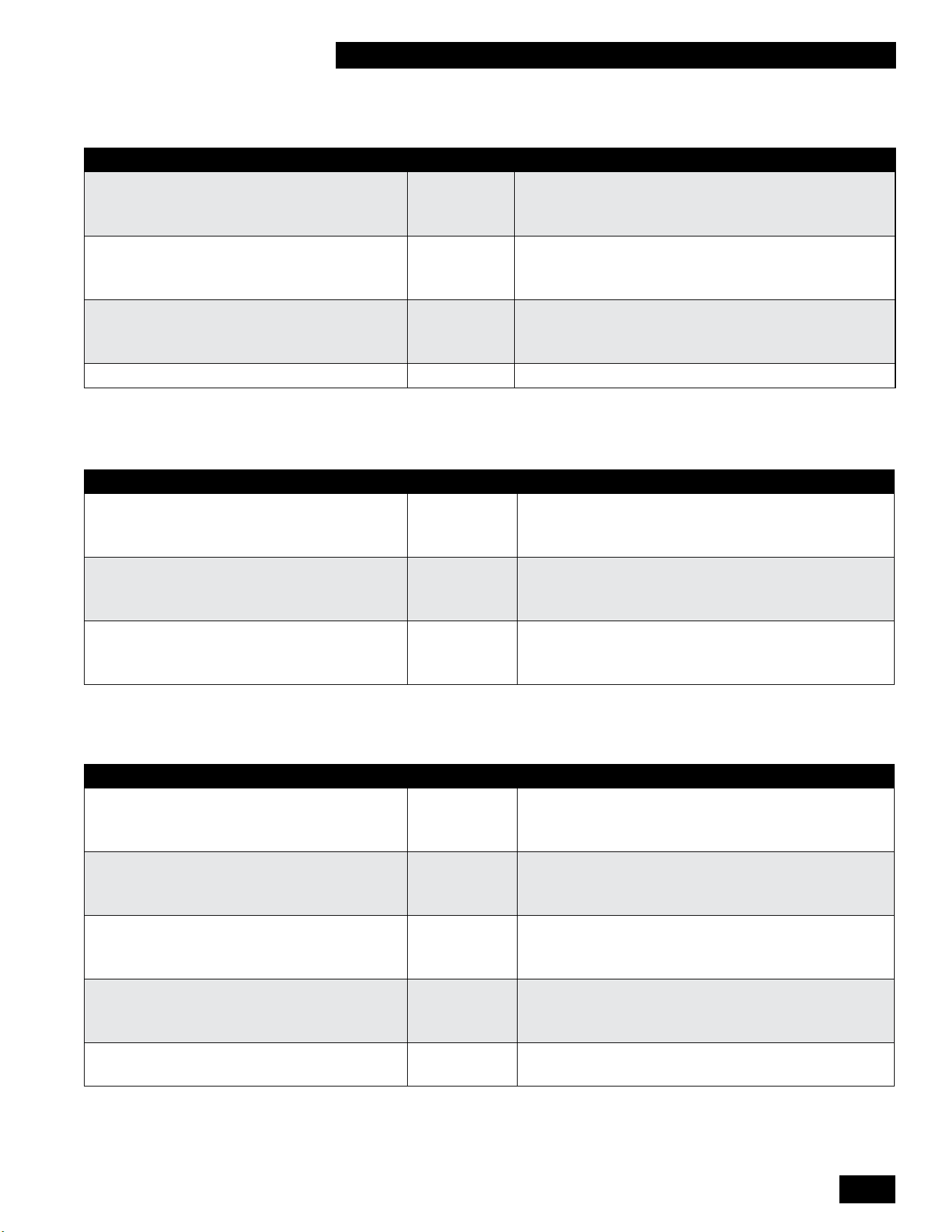
5-11
TROUBLESHOOTING
TANKLESS WATER HEATER 199
5.4.2 Domestic hot water does not reach the correct temperature
POSSIBLE CAUSES ANALYSIS POSSIBLE SOLUTION
Domestichotwaterowistoohigh. →Yes
↓No
Reducethedomestichotwaterow.
Setting for domestic hot water
temperature is too low.
→Yes
↓No
Increase the domestic hot water temperature.
Insucientheattransferduetocalciumor
contamination in the domestic hot water-sided
central heating unit.
→Yes
↓No
De-calcifyorushthedomestichotwater-sidedcentral
heating unit.
Theueisblocked.
→Yes Checktheue.
5.4.3 Burner ignites loudly
POSSIBLE CAUSES ANALYSIS SOLUTION
Inlet pressure is too high. →Yes
↓No
The gas pressure regulator may be defective. In that case,
contact the energy company.
Ignition distance is incorrect. →Yes
↓No
Replace the ignitor including the ignition cable.
Gas-air control is not correctly
adjusted.
→Yes Checkand/oradjustcombustionwithacalibrated
combustion analyzer.
5.4.4 Burner resonates
POSSIBLE CAUSES ANALYSIS SOLUTION
Gas inlet pressure lower than 4“ w.c.
or sometimes disappears.
→Yes
↓No
The gas pressure regulator may be defective. Contact the
energy company.
Thereisrecirculationofuegases. →Yes
↓No
Checktheueandairsupplyduct.
Gas-aircontrolisnotcorrectlyadjusted. →Yes
↓No
Checkand/oradjustcombustionwithacalibrated
combustion analyzer.
Burner seal is defective. →Yes
↓No
Replace the burner seal.
Burner is defective. →Yes Replace the burner.

INSTALLATION AND OPERATION INSTRUCTIONS
5-12
TANKLESS WATER HEATER 199
This page is intentionally left blank.
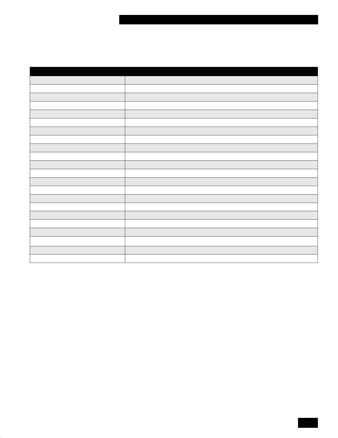
6-1
REPLACEMENT KITS
TANKLESS WATER HEATER 199
6.0 REPLACEMENTS KITS
Replacement Kit Numbers Replacement Kit Description
P-081014 Conversion To Propane - Venturi 375
P-081024 Conversion To Natural Gas - Venturi 375
P-081414 Conversion To Low Caloric Gas - Venturi 375
P-081134 Replacement kit: Flue Temperature Sensor
P-081144 Replacement kit: Ignitor
P-081174 Replacement kit: EBM Fan
P-081234 Replacement kit: Gas Valve
P-081294 Replacement kit: Temperature Sensor Heat Exchanger
P-081304 Replacement kit: Condensate Trap Tankless Water Heater 199
P-081334 Replacement kit: Controller Box White
P-081384 Replacement kit: Burner 160 - 199
P-081444 Replacement kit: Flow Sensor (Clip only)
P-081454 Replacement kit: Maintenance Set Heat Exchanger
P-081494 Replacement kit: Bypass Wiring
P-081504 Replacement kit: Ignition Wiring
P-081534 Replacement kit: Sensor Wiring Tankless
P-081574 Replacement kit: Ignition Line Complete
P-081694 Replacement kit: Temperature Sensor Supply (Clip 22mm)
P-082424 Replacement kit: Bypass valve
P-081784 Replacement kit: Temperature Sensor DHW (Clip 15mm)
P-081794 Replacement kit: Controller Box Black
P-081814 Replacement kit: Strainer
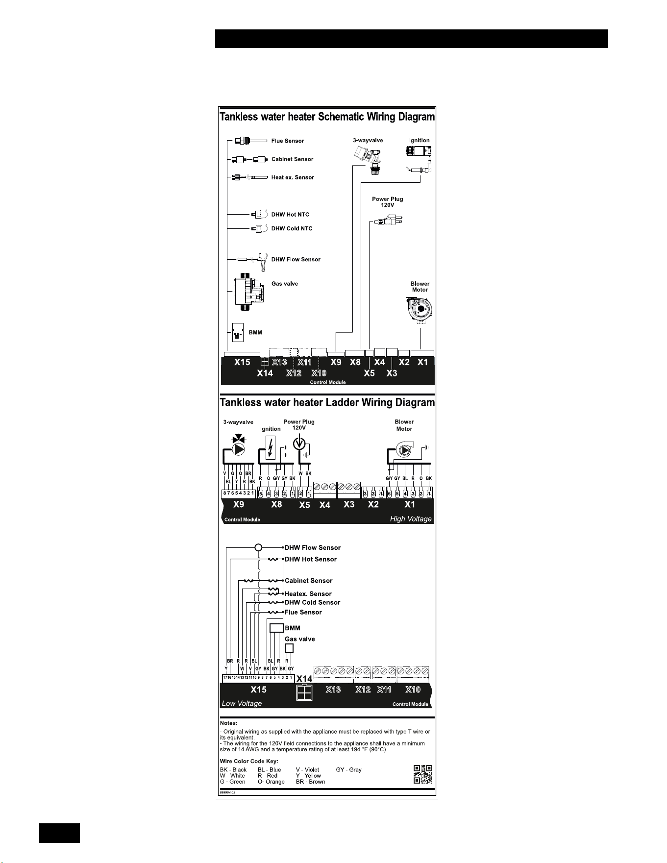
INSTALLATION AND OPERATION INSTRUCTIONS
6-2
TANKLESS WATER HEATER 199
7.0 WIRING DIAGRAMS
Diagram 6.2-1: Schematic wiring diagram
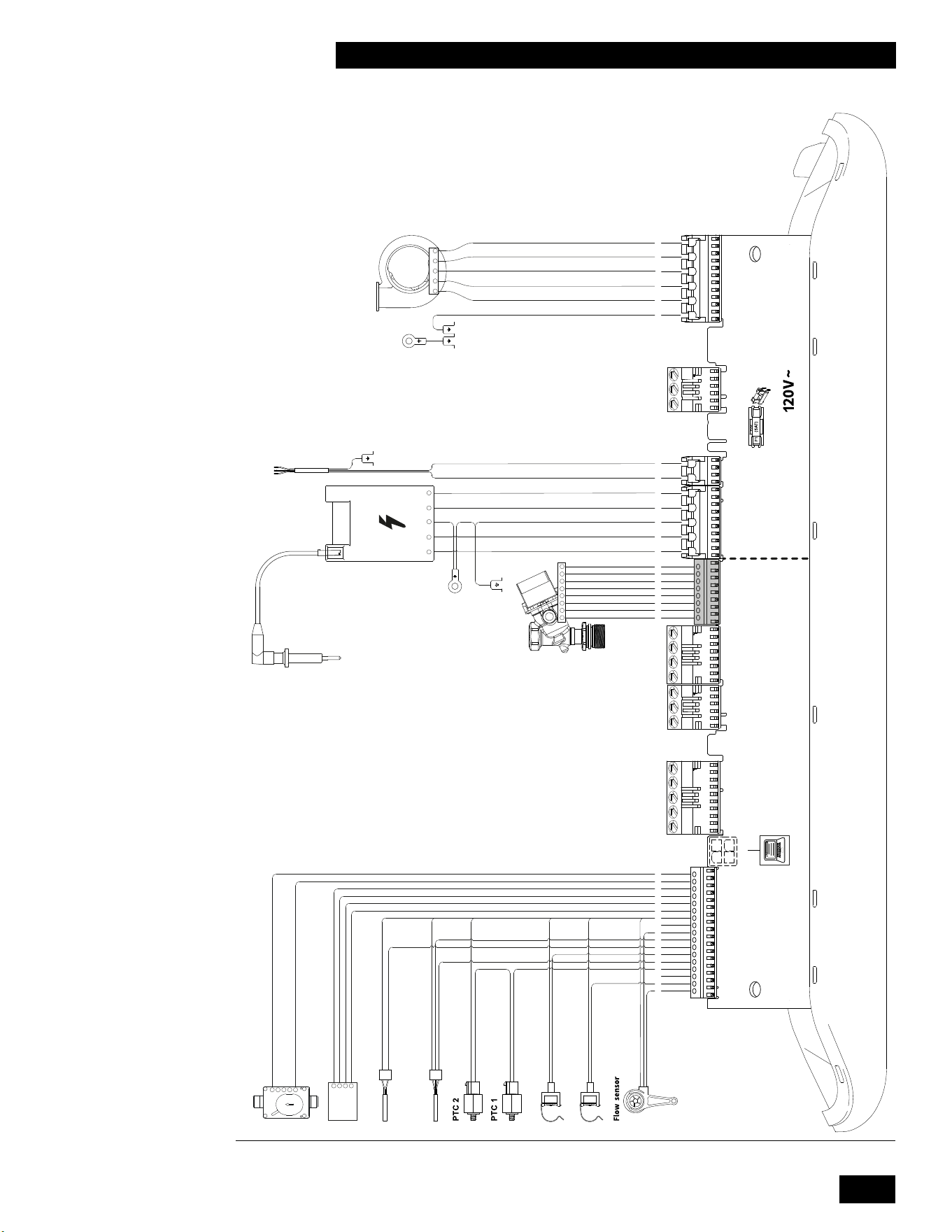
6-3
DIAGRAMS
TANKLESS WATER HEATER 199
17
16
1415
13
12 11 10 9 8 7
6
5 4 3 2
1
Domestic hot water sensor S3
Domestic cold water sensor S4
Heat exchanger sensor S0
Flue sensor S5
BMM
4
3
2
1
5
4
3
2
1
Gasvalve
X15
(24V=)
X14
PC
12 12345
X13
(24V =)
N/A
X9
(24V =)
X11
(24V =)
N/A
X10
(24V =)
N/A
X8
(120V ~)
X5
(120V ~)
Ignition unit
Burner controller
123456
Earth connections
heat exchanger
Power cord
Eart connections
burner controller
Fan
Ignition pin
Electronic bypass
valve
24V =
3
2
1
4
3
5
http://www.intergasverwarming.nl
X3
(120V ~)
N/A
12345
X1
(120V ~)
8 7
6
5 4 3 2
1
8
7
6
5
4
3
2
1
120V~ / 60Hz
Diagram 6.2-2: Electrical wiring diagram
INSTALLATION AND OPERATION INSTRUCTIONS
6-4
TANKLESS WATER HEATER 199
INSTALLATION & COMMISSIONING REPORT
Water Heater Details:
Model Number _____________________ Serial Number ______________________________________________
Date of Installation ______________ Address of installation __________________________________________
_____________________________________________________________________________________________
User contact information _______________________________________________________________________
Installer Information Company ___________________________________________________________________
Address ______________________________________________________________________________________
Phone/Fax/E mail ____________________________________________________________________________
__
Fuel
Natural Gas
Propane
Gas Supply Pressure (high re) _______ Inches w.c. Measured Rate of Input (high re) ____________ Btu/hr
Installation instructions have been followed and completed (Section 1 of Installation and Operating Instructions).
Check-out procedures have been followed and completed (Section 3 of Installation and Operating Instructions).
Leak testing completed
gas piping
venting system
Fan and combustion components
Air purge completed
Relief Valve correctly installed and piped
Relief valve “try lever” test performed
Condensatetraplled
Condensatedrainclearandfreeowing
Condensate Neutralization? Yes/No
IgnitionSafetyShutotestcompleted.Flamecurrentreading-Highre_______µA-Lowre_______µA
Owner advised and instructed in the safe operation and maintenance of the unit.
Information regarding the unit and installation received and left with owner
Combustion Readings - recommended, but optional (required for fuel
conversion):
CO
2
_____________ % O
2
______________ % CO ____________ ppm
Fluetemperature_________Returnwatertemperature(measuresimultaneouslywithuetemp.)_______________
Commissioning has been completed as listed on this report - Installer Signature _____________________________
This installation & commissioning report should remain with the Water Heater for future reference during
maintenance and repair.
6-5
INSTALLATION AND OPERATING INSTRUCTIONS
TANKLESS WATER HEATER 199
SERVICE RECORD
DATE LICENSED CONTRACTOR DESCRIPTION OF WORK DONE

INSTALLATION AND OPERATION INSTRUCTIONS
6-6
TANKLESS WATER HEATER 199
NOTES

6-7
INSTALLATION AND OPERATING INSTRUCTIONS
TANKLESS WATER HEATER 199
This page is intentionally left blank.

INSTALLATION AND OPERATION INSTRUCTIONS
6-8
TANKLESS WATER HEATER 199
This page is intentionally left blank.

6-9
INSTALLATION AND OPERATING INSTRUCTIONS
TANKLESS WATER HEATER 199
This page is intentionally left blank.

84160404
Rheem Sales Co.
Montgomery, AL.
(833) 212-9276
IBC Technologies Inc.
8015 North Fraser Way
Burnaby, BC Canada V5J 5M8
(844) HEAT-IBC / (844) 432-8422
IBC Technologies USA Inc.
121 Walter A Gaines Way
Lawnside, NJ 08045
(856) 887-0544
May 2023 ©