g.1
g.2
5
4
3
6
2
1
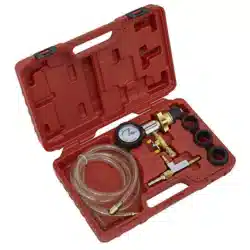
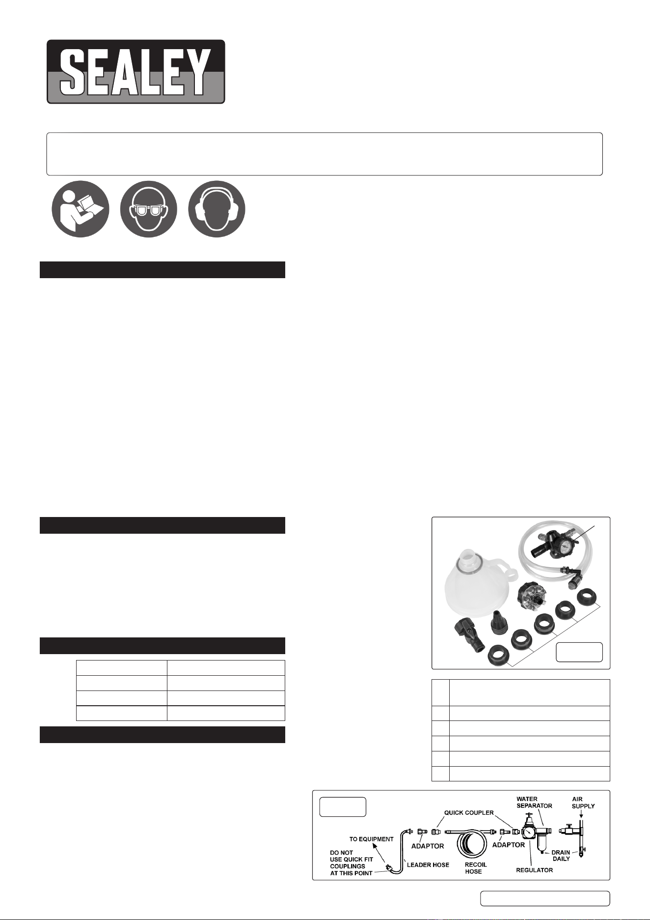
1 Gauge 0 to -1 Bar, 40mm Od, Rear
Fitting.
2 Fluid Hose.
3 Funnel Adaptor.
4 Reservoir Adaptors (6pc set).
5 Ball Valve.
6 Funnel.
4
1. SAFETY
9 Ensure all workshop safety rules, regulations and conditions are complied with when using this tool.
WARNING! Disconnect from the air supply before changing accessories or servicing.
9 Maintain the equipment in good condition and replace any damaged or worn parts. Use genuine parts only. Unauthorised parts may be
dangerous and will invalidate the warranty.
WARNING! Check that correct air pressure is maintained.
9 Keep air hose away from heat, oil and sharp edges. Check air hose for wear before each use and ensure that all connections are
secure.
9 Wear approved safety eye and ear protection (available from your Sealey supplier).
9 Keep this tool clean and in good working order for best and safest performance.
8 DO NOT use the tool for a task it is not designed to perform.
WARNING! DO NOT use the tool if it is damaged or thought to be faulty. Contact your local service agent.
8 DO NOT drop, throw or abuse the tool.
8 DO NOT carry the tool by the air hose, or yank the hose from the air supply.
8 DO NOT operate if you are tired or under the inuence of alcohol, drugs or intoxicating medication.
8 DO NOT direct air from the air hose, at yourself or others.
9 Keep children and unauthorised persons away from the work area.
9 When not in use, disconnect from the air supply and store in a safe, dry, childproof location.
WARNING! The warnings, cautions and instructions discussed in this instruction manual cannot cover all possible conditions and
situations that may occur. It must be understood that common sense and caution are factors which cannot be built into this product, but
must be applied by the operator.
2. INTRODUCTION
Eliminates the introduction of bubbles and airlocks into the cooling system and dramati-
cally reduces system lling time. No more time-consuming cooling system bleeding and
messy spills to clean up. Automatically conducts system leak test. Simple operation re-
quires a workshop air supply and does not require a ddly interchange of vacuum and
uid hoses. Rell the system by attaching the ller hose and opening the valve allowing
your premixed coolant to ow into the system. The system can be lled manually via
the funnel, which has a built-in shut-o valve that helps prevent airlocks. Supplied with
a 1.25m ller hose, six reservoir adaptors 31, 35, 40, 42, 45mm, a cone adaptor and a
storage case.
3. SPECIFICATION
4. AIR SUPPLY
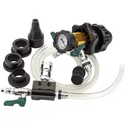
4.1. Recommended hook-up is shown in g.2. Ensure that
both coolant and vacuum taps are in the ‘o’ position
(fully to the left or right) when connecting the air supply.
Fig.1. Shows both taps in the open position (in-line with
the outlet/inlet pipe).
WARNING! Ensure that the air supply is clean and does
not exceed 100psi. Too high an air pressure or unclean
air will shorten the life of the ller due to excessive wear,
and may be dangerous, causing damage and/or personal
injury.
4.1.1. Drain the air tank on the compressor daily.
4.1.2. Clean compressor air inlet lter weekly.
COOLING SYSTEM VACUUM PURGE & REFILL KIT
Thank you for purchasing a Sealey product. Manufactured to a high standard, this product will, if used according to these
instructions, and properly maintained, give you years of trouble free performance.
VS0046 Issue 1 20/11/24
Original Language Version
© Jack Sealey Limited
Refer to
instructions
I MPORTANT: PLEASE READ THESE INSTRUCTIONS CAREFULLY. NOTE THE SAFE OPERATIONAL REQUIREMENTS, WARNINGS & CAUTIONS. USE
THE PRODUCT CORRECTLY AND WITH CARE FOR THE PURPOSE FOR WHICH IT IS INTENDED. FAILURE TO DO SO MAY CAUSE DAMAGE AND/OR
PERSONAL INJURY AND WILL INVALIDATE THE WARRANTY. KEEP THESE INSTRUCTIONS SAFE FOR FUTURE USE.
MODEL NO: VS0046
Model No: VS0046
Air Inlet Size: 1/4”BSP
Fluid Hose Length: 1.25m
Nett Weight: 1.06kg
Wear eye
protection
Wear ear
protection

4.1.3. Line pressure should be increased to compensate for unusually long air hoses (over 8 metres). The minimum hose size should be ¼”
I.D. And ttings must have the same internal bore.
4.1.4. Keep hose away from heat, oil and sharp edges. Check hose for wear and make certain that all connections are secure.
5. OPERATION
WARNING! Ensure that you read, understand and apply safety instructions before use.
5.1. PREPARATION.
5.1.1. Set vehicle heater control to ‘On’ and/or ‘Hot’.
5.1.2. Drain and ush the coolant system.
5.1.3. Inspect all coolant system components and repair/replace any unserviceable items.
5.1.4. Prepare a suitable coolant mix (refer to the vehicle manufacturer’s service manual). Mix 10% more than the system’s volume, to ensure
that the ller hose will always be submerged.
5.1.5. Connect the ller to the compressed air system, as described in Section 4.
5.2. SUCTION FILLING.
5.2.1. Raise the container of coolant level with the lling point. Insert the adaptor (using the appropriate rubber adaptor if required) to obtain
a tight t into the ller neck of the radiator (or header tank, if tted). Use the extension pipe if required. Support the air line so that the
ller is not pulled o-centre.
NOTE: On some vehicles tted with an overow tank, it may be necessary to clamp the overow hose.
5.2.2. Place the ller hose into the container of coolant. Ensure that the lter on the end of the hose remains submerged throughout the lling
process.
5.2.3. Check that the coolant tap is in the closed (fully to the right or left) position.
NOTE: During the following procedure the radiator hoses will collapse under the vacuum being generated - this is normal.
5.2.4. Open the vacuum tap (middle position) and allow the air to evacuate until the gauge reads 50-60inHg.
5.2.5. When the gauge is reading 50-60inHg and has stopped moving, close the vacuum tap, by pushing the lever fully to the left or right.
Continue to check the gauge reading over the next 3 minutes. If the gauge reading drops there is a system leak which will require
locating and rectifying before proceeding further.
5.2.6. Apply a downward force during lling. Open the coolant tap fully and coolant will ow into the cooling system. For best results raise the
coolant container above the level of the ller neck.
5.2.7. When the gauge reads 0inHg, turn the coolant tap to the o position and remove the ller from the lling point. If necessary top up the
coolant to the specied level and ret the pressure cap. The system is lled and free from air locks.
5.2.8. Start the vehicle’s engine and run until normal operating temperature is attained. Switch o the engine and allow it to cool. Top-up
coolant if necessary using the funnel.
5.2.9. It is advisable to now pressure test the system and to check the operation of the thermostat and cooling fan(s).
WARNING! Disconnect from the air supply before changing accessories, servicing or performing maintenance. Replace or repair
damaged parts.
NOTE: Use genuine parts only. Non genuine parts may be dangerous and will invalidate the warranty. Air supply faults may cause loss
of power or erratic action. Reduced compressor output, excessive drain on the air line, moisture or restrictions in air pipes or the use of
hose connections of improper size may reduce air supply.
6. MAINTENANCE
6.1. When not in use, disconnect the air supply from the ller.
6.1.1. Clean the ller with a slightly dampened cloth and store it in a safe, dry, childproof location.
Note: It is our policy to continually improve products and as such we reserve the right to alter data, specifications and component parts without prior
notice. Please note that other versions of this product are available. If you require documentation for alternative versions, please email or call our
technical team on technical@sealey.co.uk or 01284 757505.
Important: No Liability is accepted for incorrect use of this product.
Warranty: Guarantee is 12 months from purchase date, proof of which is required for any claim.
Sealey Group, Kempson Way, Suffolk Business Park, Bury St Edmunds, Suffolk. IP32 7AR
01284 757500 sales@sealey.co.uk www.sealey.co.uk
ENVIRONMENT PROTECTION
Recycle unwanted materials instead of disposing of them as waste. All tools, accessories and packaging should be
sorted, taken to a recycling centre and disposed of in a manner which is compatible with the environment. When
the product becomes completely unserviceable and requires disposal, drain any uids (if applicable) into approved
containers and dispose of the product and uids according to local regulations.
VS0046 Issue 1 20/11/24
Original Language Version
© Jack Sealey Limited