1
USEPHOENIX.COM | 800-533-7533
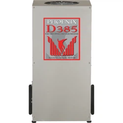
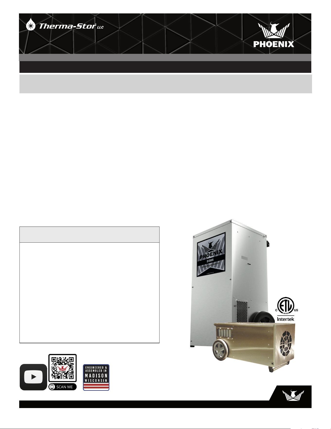
The Phoenix D385 provides the perfect combination of
features and performance the restoration industry has been
craving in a desiccant dehumidifier. Designed to operate
vertically or horizontally, the Phoenix D385 provides the
wide operating range and ultra-low grains of a desiccant
with the water removal capacity of the largest LGR’s in
cabinet dimensions identical to our popular Phoenix
200 Max.
The D385 delivers 385 CFM of ultra-low grain process air
and removes an incredible 130 pints per day at AHAM
conditions. The true four hole configuration* allows the
Phoenix D385 to be located in the affected area with the
75 CFM re-activation air stream isolated from the drying
chamber. Three hole designed units** inherently pull
unaffected and/or outside air into the drying chamber. The
D385’s four hole design allows the restoration contractor
to set-up for effective positive, neutral or negative pressure
operation.
Able to operate vertically or horizontally, the D385 will fit
inside most crawlspaces. Having the D385 securely inside,
rather than outside the crawlspace access, deters the
possibility of tampering with the dehumidifier or the set-
up. The 385 CFM of process air will provide 3 ACH on an
affected area up to 7000 cubic feet.
The Phoenix D385 is easy to transport and set-up. The
D385 will fit on your truck in the areas already designed
for your LGR’s and will move around the jobsite with the
same portability. All the power to the unit is provided by
two 115 volt grounded power cords. Simply plug the cords
into separate 15 amp circuits. Each cord draws only 12
amps to power the D385. The re-activation air stream is
ducted through 6” flex duct provided with the unit and stores
conveniently in the top of the unit.
*Having completely separate process and regeneration airstreams.
**Where regeneration airstream is pulled from the process airstream.
The Phoenix D385 Desiccant Dehumidifier
• Ultra low grains
• Wide operating range
• 130 pints per day @ AHAM
• Operates vertically or horizontally
• Process airflow 385 CFM
• Two 23’ power cords:
12 Amps per cord
24 Amps
115 Volts/60 Hz
• Unlimited ducting possibilities
• Legendary stainless construction
Phoenix D385
PN
4026700
TS-1148
04/22 Rev. B
Installation, Operation & Service Instructions
– READ AND SAVE THESE INSTRUCTIONS –
OWNER’S MANUAL
D385 | DESICCANT DEHUMIDIFIER
4201 LIEN RD. • MADISON, WI 53704
Specifications subject to change without notice.

2
USEPHOENIX.COM | 800-533-7533
• In order to avoid hazard due to inadvertent resetting of
the thermal cutout, this appliance must not be supplied
through an external switching device, such as a timer, or
connected to a circuit that is regularly switched on and
off by the utility
• It is designed to be used INDOORS ONLY.
• If used on a water loss work site, plug it into GROUND
FAULT CIRCUIT INTERRUPT (GFCI) OUTLETS
• The air inlet on top and the side outlet must be at least
1 foot from walls and other air flow obstructions.
• DO NOT use the Phoenix D385 as a bench or table.
• Do not operate the Phoenix D385 at an altitude higher
than 32,800 ft (10,000m)
2 Specifications
Part No. 4026700
Power 2 circuits: 12 Amps, 115 VAC each
24 Amps total power consumption
Water 130 pints per day AHAM
Removal
Blower 385 CFM Process Airflow
75 CFM Reactivation Airflow
Cord Length 2ea. 23ft power cords
Operating 10-120°F
Range
Filters Process filter size: 16” x 20” x 2”
Reactivation filter size: 12” x 12” x 1”
Duct Process Inlet: 12” Flex-Duct (optional)
Connections Process Outlet: 10” Lay Flat collar (optional)
Reactivation Inlet: 6” Flex-Duct (optional)
Reactivation Outlet: 6” Flex-Duct (required)
External Static 0-0.4” WC Process
Pressure 0-0.25” WC Reactivation
Warranty One year Parts and Labor
Dimensions:
Machine Shipping
Width 24-1/4” 27-1/2”
Height 40” 45-1/2”
Depth 21-3/8” 22”
Weight 105 Lbs. 130 Lbs.
Popular Accessories
4026859 6” Metalized Polyester Flex-Duct 25’ (Standard)
4020128 6” Insulated Flex-Duct 25’
4024750 12” Metalized Polyester Flex Duct 25’
4022537 10” Lay Flat Duct 500’
4024935 10” Lay Flat Duct 250’
Read the operation and maintenance instructions carefully before
using this unit.
Proper adherence to these instructions is essential to
obtain maximum benefit from your Phoenix D385 dehumidifier.
Table of Contents
Introduction ................................................................................1
1. Safety Precautions .............................................................2
2. Specifications .....................................................................2
3. Operation .............................................................................3
3.1 How The Phoenix D385 Works .................................3
3.2 Avoiding Secondary Damages ..................................3
3.3 Electrical Requirements ............................................. 3
3.4 Control Panel ...............................................................4
3.4A Power Switch ....................................................... 4
3.4B Pilot Light .............................................................4
3.4C Hour Meter ...........................................................4
3.5 Location ........................................................................4
3.6 Ducting Connections ................................................... 4
3.7 Ducting Options ...........................................................4
3.8 Storage and Transportation .......................................4
4. Maintenance .......................................................................4
4.1 Air Filter Replacement ...............................................4
4.2 Blower Motor and Rotor Drive Motors ......................5
4.3 Desiccant Rotor Cassette Assembly ........................5
5. Service .................................................................................5
5.1 Warranty .......................................................................5
5.2 Technical Descriptoin .................................................5
5.3 Normal Operation ........................................................6
5.4 Troubleshooting ...........................................................6
6. Wiring Diagram ..................................................................6
7. Service Parts List ...............................................................7
Warranty ..............................................................................8
Serial No. ___________________________
Purchase Date ______/______/_____
Dealer’s Name ___________________________________
1 Safety Precautions
• This appliance is not intended for use by persons
(including children) with reduced physical, sensory,
or mental capabilities, or lack of experience and
knowledge, unless they have been given supervision or
instruction concerning use of the appliance by a person
responsible for their safety
• The appliance shall be installed in accordance with
national wiring regulations
• Please allow one foot of clearance for the inlets and
outlets of the unit
• Never operate a unit with a damaged cord. If the
power cord is damaged, it must be replaced by the
manufacturer, its service agent, or a similarly qualified
person in order to avoid a hazard
3
USEPHOENIX.COM | 800-533-7533
Process Air Filter Replacement
4021475 16” x 20” x 2” MERV 11 Filter (Standard)
4024969 16” x 20” x 2” MERV 6 Filter (Optional)
4022164 16” x 20” x 2” MERV 14 Filter (Optional)
Reactivation Air Filter Replacement
4026860 12” x 12” x 1” MERV 7 Filter (Standard)
4026315 12” x 12” x 1” MERV 8 Filter (Optional)
3 Operation
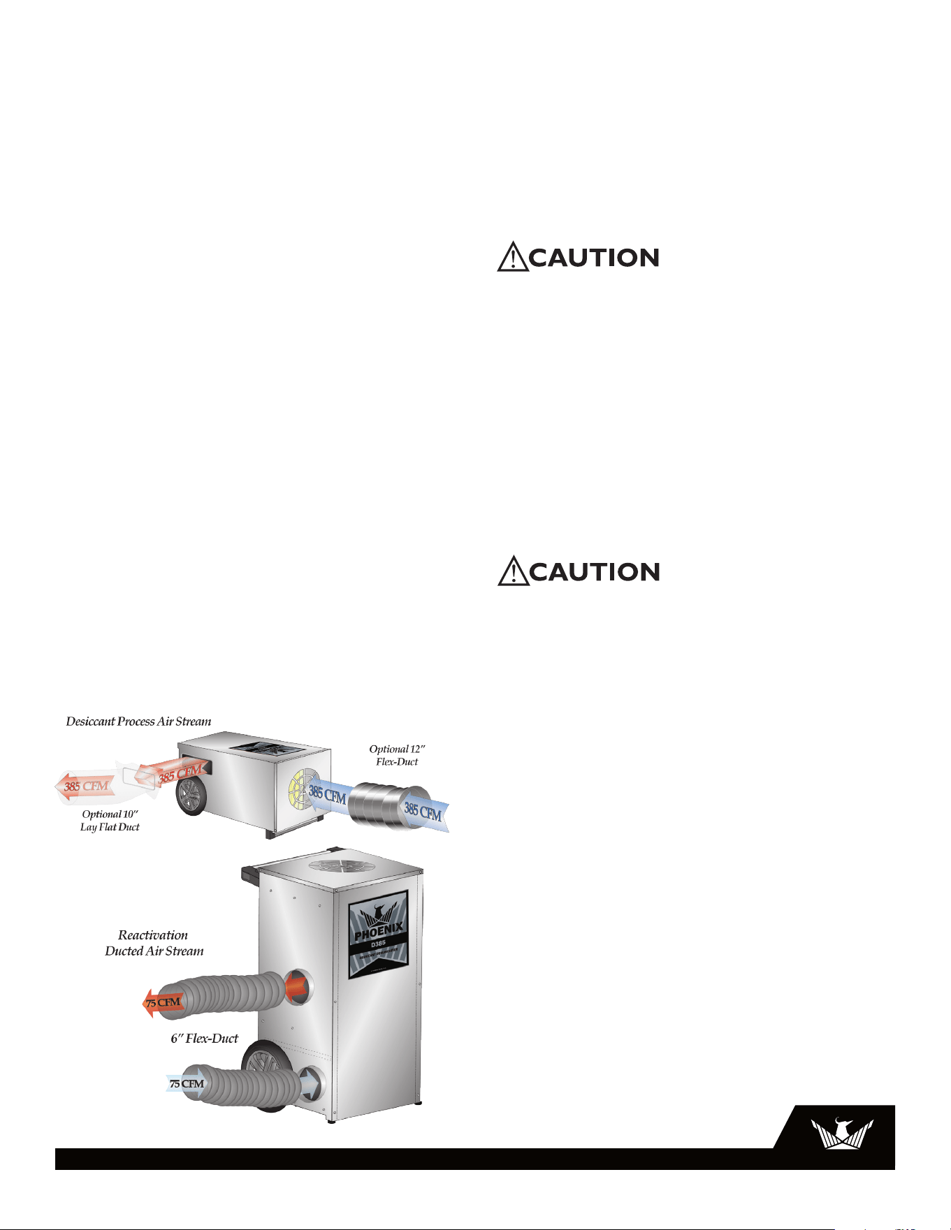
3.1 How the Phoenix D385 works
Your Phoenix D385 has two separate air streams that run
through it – Process (Fig. 1) and Reactivation (Fig. 2).
Note: Check for airflow at all inlets and outlets. DO NOT run
unit if no airflow is detected.
Process Air Stream:
P1 – 385 CFM of air enters (12”flex) the top of the machine
and...
P2 – ...water vapor from incoming air is deposited on the
desiccant wheel.
P3 – 385 CFM of dry air exits (10” lay flat) the machine.
Reactivation Air Stream:
R1 – 75 CFM of air enters (6”flex) the lower-side of the
machine and...
R2 – passes over the heater coils.
R3 – Water vapor is picked up from the desiccant wheel by
the hot air and...
R4 – ...75 CFM of wet air exits (6”flex) the machine.
3.2 Avoiding Secondary Damages
The D385 is a powerful tool capable of removing a great
deal of water from most environments. Care must be
taken to avoid secondary damages of over-drying and or
unexpected condensation.
Your Phoenix D385 removes vapor water from the incoming
process air stream (Fig. 1) and transfers it to the outgoing
reactivation air stream (Fig. 2). The reactivation exhaust air
is hot and wet.
Take care to prevent the reactivation exhaust air stream
from causing secondary damage due to condensation.
If the reactivation exhaust air stream cools below its
dewpoint liquid water will condense inside the duct work
creating puddles. If the reactivation exhaust air stream is not
exhausted completely from the structure it can also cause
secondary water damage.
Your Phoenix D385 does not produce liquid water internal
to the machine. There is no condensate pump and no drain
hose.
The D385 desiccant dehumidifier will continue to remove
water from already dry, cold air. It is possible to over-dry
objects and or structures.
Care must be taken to avoid secondary damages due to
over-drying.
3.3 Electrical Requirements
When used on a water loss work site, ground fault circuit
interrupter (GFCI) outlets are required.
Your Phoenix D385 requires a total of 24 amps, 115VAC.
In order to run at all, this machine must be plugged into
two separate circuits each with a minimum of 12 amps
dedicated capacity available.
The D385 has two separate power cords, each cord must
be plugged into its own 15 amp circuit. If both cords are
plugged into the same 15 amp circuit this circuit will trip
when the unit is turned on.
Another situation to avoid is that one or both of the circuits
which the D385 is using can be tripped by other appliances
drawing power from either circuit. This can happen well
after a job site has been set-up as in the case with a freezer
compressor turning on.
Care must be taken to insure that the D385 always has
sufficient power available to run without tripping breakers or
blowing fuses.
If your location requires the use of an extension cord, use
safe techniques in selection and connection. Such cords
must be grounded and rated for carrying 12 amps: 14
gauge minimum for one extension less than 25ft in length
or 12 gauge for one extension less than 50ft in length.
Figure 1: Desiccant process air stream.
Figure 2: Desiccant reactivation air stream.
P1
P2
P3
R1
R3
R2
4
USEPHOENIX.COM | 800-533-7533
3.4 Control Panel
3.4A Power Switch
The D385 has one control device, the power switch. When
the power switch is moved to the “on” position your portable
desiccant is dehumidifying. The machine will continue to
dehumidify in all conditions until the power is turned off:
There is no dehumidistat (see over-dry warning section 2.2).
3.4B Pilot Light
The power indicator lamp illuminates to indicate that the
D385 is functioning properly. This indicator is helpful when
a job site is too noisy to know what equipment is running
properly. At a glance from across the room the operator can
verify that the D385 is operating as it should.
3.4C Hour Meter
The hour meter will run whenever your D385 is on. This
digital hour meter measures the cumulative time of
operation in one-tenth hour increments. This non-resettable
time is often used to verify hours on a job or to schedule
maintenance. When the D385 is un-plugged the timer will
continue to hold and display the cumulative hours run.
3.5 Location
Note the following precautions when locating the Phoenix
D385:
• It is designed to be used INDOORS ONLY.
• If used on a water loss work site, plug it into GROUND
FAULT CIRCUIT INTERRUPT (GFCI) OUTLETS
• DO NOT use the Phoenix D385 as a bench or table.
• The air inlet on top and the side outlet must be at least 1
foot from walls and other air flow obstructions.
• If the humid area is very large, dehumidification can be
improved by adding an outlet duct to circulate process air
to stagnant areas.
3.6 Ducting Connections
Using excess duct length significantly reduces air flow
volume through duct. This is true in any application. If the
job at hand needs a short length of duct, cut a section to the
appropriate length. If air flow is restricted by excess length,
performance will suffer. The same can be said of excess
bends in the ducting.
Three different duct sizes are used on the D385. All
ducting materials are available from Therma-Stor LLC (see
accessories list section 1).
Process in: 12” flex duct.
To attach flex duct to the process air intake, push the wire of
the first couple of loops down below the four tabs in the top
cover.
Process out: 10” diameter lay flat plastic duct.
When inflated this ducting forms a 10” circle. 10” lay flat
ducting attaches to the D385 by means of a 12”x 6” wire
rectangle. To attach lay flat ducting to the process exhaust
air (Fig. 1, P3), put the plastic duct end through the collar
center and roll the plastic ducting’s end outward so that it
overlaps the outside of the collar. The duct and collar quickly
attach to the D385 by snapping over the four screw posts
surrounding the process air exhaust (Fig. 1, P3).
Reactivation in & out: 6” flex duct.
Both reactivation air streams use the same type of duct
connections.
The 6” flex ducting connections on the D385 consist of a
detachable 6” starting collar. Slide 6” flex ducting over the
starting collar and zip-tie or duct tape in place. To remove
the starting collar (and its attached ducting length) depress
the snap button and rotate the duct collar 15° clockwise.
After rotating pull the duct collar straight out from the
cabinet. Flex duct and collar may be stored beneath top
cover.
3.7 Ducting Options
3.8 Storage and Transportation
The Phoenix D385 can be transported and stored in either
upright or horizontal positions.
There is a storage compartment under the top cover of your
dehumidifier. This compartment is large enough to store
reactivation collars, power cords, filter (as used), as well as
additional small items that you may require on your job site.
4 Maintenance
4.1 Air Filter Replacement
The Phoenix D385 is equipped with two pleated fabric air
filters that must be checked regularly.
Process air stream filter:
This 16”x20”x2” filter is located in the top of your D385
underneath the top cover. The stock filter supplied carries
a MERV-11 filtration efficiency rating. This filter prevents
loading the desiccant wheel with foreign matter.
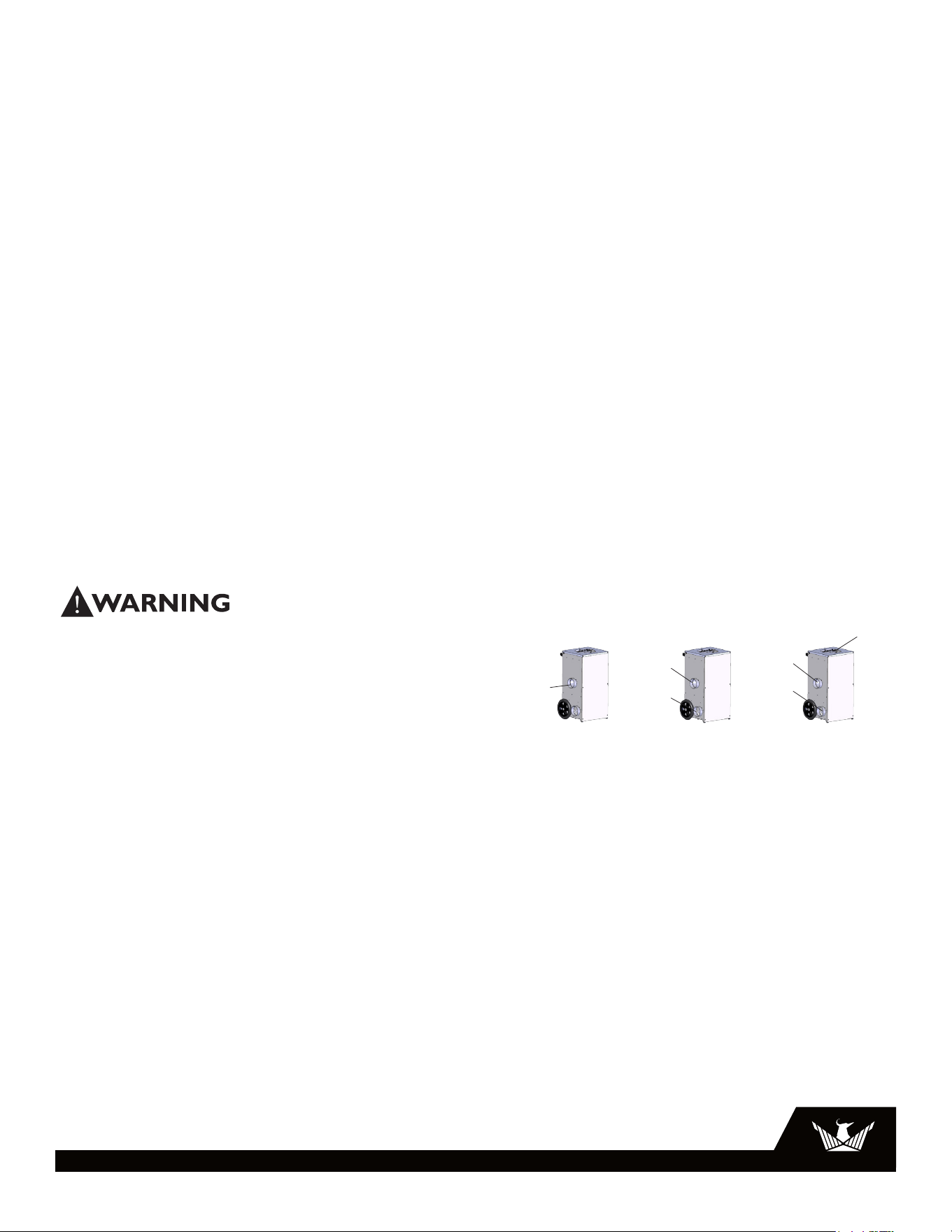
PROCESS INLET
REACTIVATION INLET
NEGATIVE
PRESSURE The
Standard Setup
If the D385 is in the
drying chamber, air is
being pulled into the
chamber to compensate
for the negative pressure
created by the 75 CFM
of reactivation air being
ducted out.
REACTIVATION OUTLET
Must always be ducted out
of the affected area
NEUTRAL
PRESSURE
The reactivation inlet and
outlet are ducted from
outside the drying area.
This can be benecial if
the air outside the drying
chamber is very damp.
REACTIVATION OUTLET
Must always be ducted out
of the affected area
REACTIVATION INLET
Duct in from outside the
affected area
POSITIVE
PRESSURE
The process inlet is ducted
in from outside the drying
chamber. This can be
benecial if the outside air
is dry.
REACTIVATION OUTLET
Must always be ducted out
of the affected area
REACTIVATION INLET
Duct in from outside the
affected area
PROCESS INLET
Duct some or all
air from outside
affected area
P/N 4037582
IDENTIFYING INLETS AND OUTLETS
PROCESS AIR
STREAM
• Air is pulled
into the inlet
• Humidity is
adsorbed by
the desiccant
wheel
• Dry air blows
from the
outlet
REACTIVATION OUTLET
PROCESS OUTLET
REACTIVATION AIR
STREAM
• Air is pulled into the
inlet
• It is heated to drive
moisture out of the
desiccant wheel
• Hot moist air exhausts
from the outlet
NOTE: LIQUID WATER
MAY CONDENSE IN THE
REACTIVATION OUTLET
DUCT. SLOPE THE DUCT
DOWNWARD TO PREVENT
DAMAGE TO THE UNIT.
MINIMIZE THE DUCT
LENGTH AND USE THE
STRAIGHTEST PATH
POSSIBLE.
Refer to owner’s manual for additional setup information
Scan for more
information on
the D385
PROCESS INLET
REACTIVATION INLET
NEGATIVE
PRESSURE The
Standard Setup
If the D385 is in the
drying chamber, air is
being pulled into the
chamber to compensate
for the negative pressure
created by the 75 CFM
of reactivation air being
ducted out.
REACTIVATION OUTLET
Must always be ducted out
of the affected area
NEUTRAL
PRESSURE
The reactivation inlet and
outlet are ducted from
outside the drying area.
This can be benecial if
the air outside the drying
chamber is very damp.
REACTIVATION OUTLET
Must always be ducted out
of the affected area
REACTIVATION INLET
Duct in from outside the
affected area
POSITIVE
PRESSURE
The process inlet is ducted
in from outside the drying
chamber. This can be
benecial if the outside air
is dry.
REACTIVATION OUTLET
Must always be ducted out
of the affected area
REACTIVATION INLET
Duct in from outside the
affected area
PROCESS INLET
Duct some or all
air from outside
affected area
P/N 4037582
IDENTIFYING INLETS AND OUTLETS
PROCESS AIR
STREAM
• Air is pulled
into the inlet
• Humidity is
adsorbed by
the desiccant
wheel
• Dry air blows
from the
outlet
REACTIVATION OUTLET
PROCESS OUTLET
REACTIVATION AIR
STREAM
• Air is pulled into the
inlet
• It is heated to drive
moisture out of the
desiccant wheel
• Hot moist air exhausts
from the outlet
NOTE: LIQUID WATER
MAY CONDENSE IN THE
REACTIVATION OUTLET
DUCT. SLOPE THE DUCT
DOWNWARD TO PREVENT
DAMAGE TO THE UNIT.
MINIMIZE THE DUCT
LENGTH AND USE THE
STRAIGHTEST PATH
POSSIBLE.
Refer to owner’s manual for additional setup information
Scan for more
information on
the D385
5
USEPHOENIX.COM | 800-533-7533
5 Service
CAUTION: Servicing the Phoenix D385 with its high voltage
circuitry presents a health hazard which could result in
death, serious bodily injury, and/or property damage. Only
qualified service people should service this unit.
CAUTION-ELECTRICAL SHOCK HAZARD: Electrical power
must be present to perform some tests; these tests should
be performed only by a qualified service person.
Note: Check for airflow at all inlets and outlets. Do not run
unit if no airflow is detected.
5.1 Warranty
A warranty certificate has been enclosed with this unit;
read it before any repair is initiated. If a warranty repair
is required, call the factory first at 1-800-533-7533 for
warranty claim authorization and technical assistance.
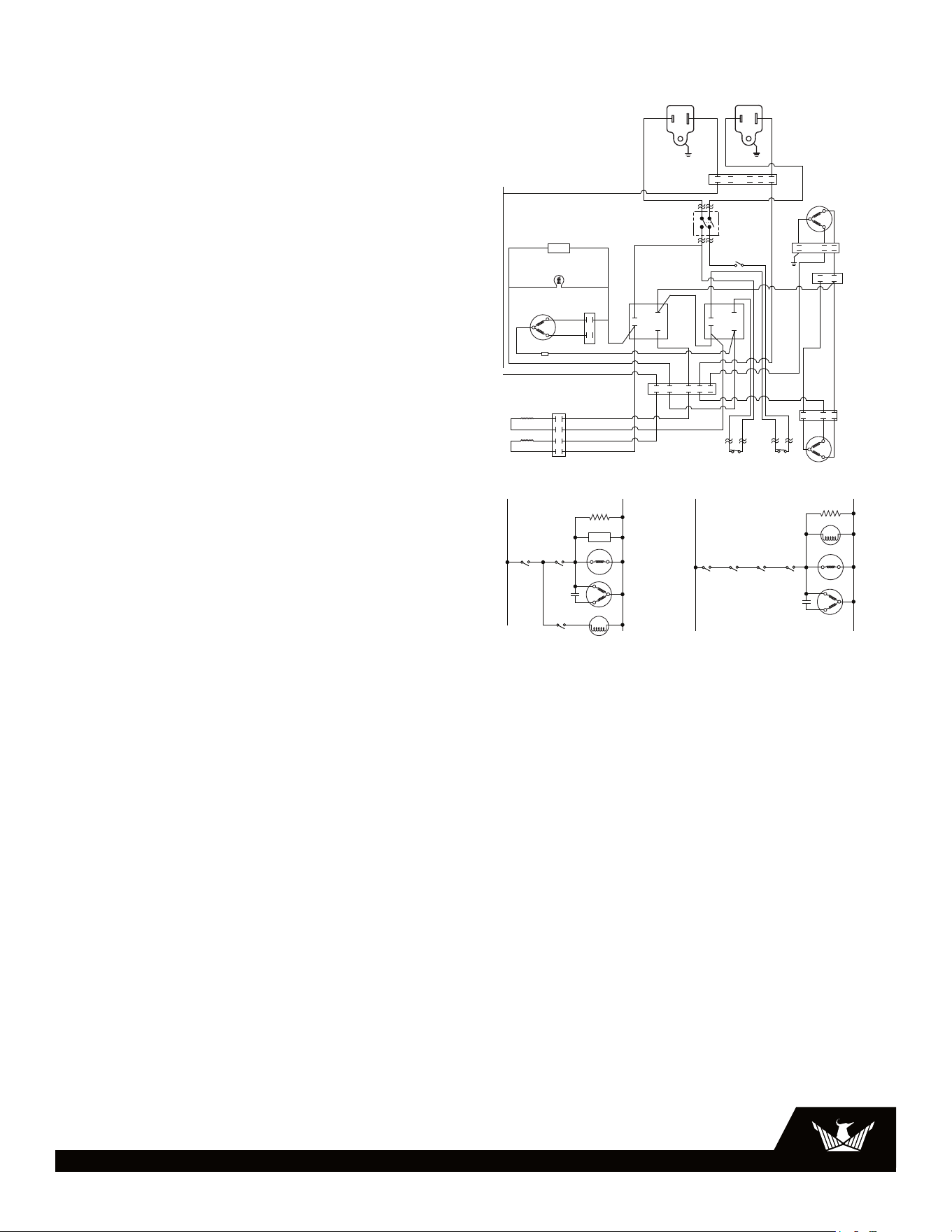
5.2 Technical Description
The D385 produces airflow using two permanent split
capacitor (PSC) blower motors. A shaded-pole gear motor
rotates the desiccant rotor via a pulley and belt. Heat for
reactivation is generated by a two-stage nichrome heating
element powered by two separate branch circuits. The
heating elements cannot be energized individually – both
cords must be plugged in for them to operate. An LED
indicator lamp illuminates when the unit is powered on. An
hour meter also counts the cumulative hours the unit has
run.
The blowers, rotor motor, heating elements, indicator lamp,
and hour meter are operated by a line-voltage control
circuit. One branch circuit (Circuit 1) delivers power to the
process blower, indicator lamp, hour meter, and a 1270W
heating element through one relay (Relay 1). A separate
branch circuit (Circuit 2) delivers power to the reactivation
blower, rotor motor, and a 1360W heating element through
a second relay (Relay 2). Circuit 1 provides power to the
coil for Relay 2 and Circuit 2 provides power to the Relay 1
coil. Because of this latching between the two circuits, the
unit cannot operate unless both cords are plugged in. With
both cords plugged in, turning on the power switch energizes
the Relay 2 coil. This energizes all of the loads on Circuit 2,
as well as the Relay 1 coil, which energizes all of the loads
on Circuit 1. If either cord is unplugged, all loads are de-
energized.
Three thermal cutout switches allow for safe operation of
the D385. Two of these cutouts are located in the heater.
If the reactivation inlet temperature is too high or if there is
insufficient reactivation airflow, the automatically-resetting
heater cutout opens and all loads are de-energized. Once
the temperature drops by a few degrees F, the switch
Reactivation air stream filter:
This 12”x12 x1” filter is located in the bottom of your D385.
To change the reactivation air filter, lay the D385 down in
a horizontal position. The filter access slot is located on
the bottom of the machine (Fig. 4). Open retainment clip,
remove old filter, and replace with fresh filter.
The stock filter supplied carries a MERV-7 filtration efficiency
rating. This filtration prevents plugging the heater or loading
the desiccant wheel with foreign matter.
Operating the unit with a dirty filter will reduce the
dehumidifier’s capacity and efficiency and may cause the
heater coil to cut out on thermal overload.
The filter can generally be vacuumed clean several times
before needing replacement. Replacement filters can be
ordered from the factory or purchased locally if available.
DO NOT operate the unit without the filters or with less
effective filters as the desiccant wheel inside the unit will
become clogged and require disassembly to clean.
4.2 Blower Motors and Rotor Drive Motor
All motors on the D385 are permanently lubricated and do
not require maintenance.
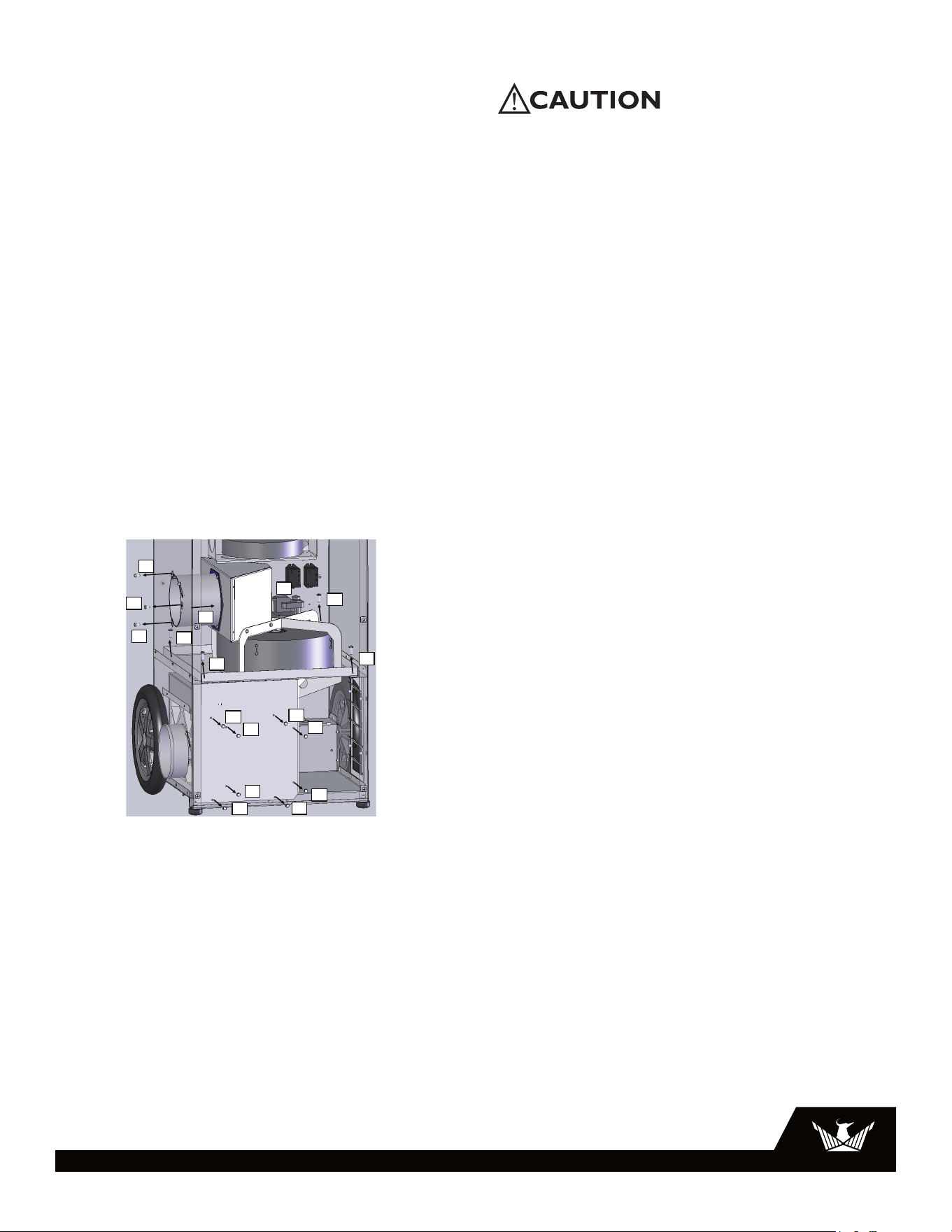
4.3 Desiccant Rotor Cassette Assembly
The cassette can be easily removed to inspect and/or clean
the seals and rotor. Reverse these steps to reinstall the
cassette.
PROCESS BLOWER
GRN 25
BLK 11
WHT 24
CORD 1 CORD 2
WHT WHTBLK
BLK
BLK
BRN
BLU 27
BLU
BLU
RED
RED
WHT 9
BLK 8
BLU 7
ORG 6
BLU
BLK
GRN
BLK
BLK
BLK
TERMINAL BLOCK
TERMINAL BLOCK
CIRCUIT 1 CIRCUIT 2
HEATER
THERM OL 1
176°F
HEATER
THERM OL 2
302°F
1360W
1270W
ROTOR MOTOR
1234
1234
REGEN CAPACITOR
REGEN BLOWER
PROC THERM
OL 140°F
MAIN POWER SWITCH
HOUR METER
PROC BLOWER PROC CAP
LIGHT
RELAY 1 RELAY 2
BLU 22
ORG 15
ORG 18
ORG 19BLU 21
BLU 20
ORG 6
ORG 15
ORG 12
ORG 28
BLK 1
ORG 14
BLK 17
BLK 11
BLK 10
BLK 10
BLU 27
WHT 4
BLK 8
BRN 5
BLK 3BLK
BLU
BRN
ORG 28
ORG 14
BLK 2
BLK 1
BLU 26
WHT 13
WHT 13
BLU 7
WHT 23
WHT 24
BLU 22
BLU 26
WHT 9
WHT 4
BLU 23
BLK 16BLK 3
BRN 5
BLK 2
WHT 23
1
2
3
4
LINE LINE
ROCKER
SWITCH POLE 1
ROCKER
SWITCH
POLE 2
NEUTRAL NEUTRAL
RELAY
CONTACT 1
1270W HEATER
1360W HEATER
HOUR METER
LAMP
HEATER
CUTOUT 1
RELAY COIL 2
PROCESS
CAPACITOR
HEATER
CUTOUT 2
PROCESS
CUTOUT
RELAY
CONTACT 2
REIGN
CAPACITOR
RELAY COIL 1
ROTOR MOTOR
REIGN BLOWER
BLU
BLK
BRN
BLU
BLK
BRN
Step 1: Remove three #10 screws holding reactivation duct in place
(1A, 1B, 1C) using 5/16” hex driver.
Push duct section (1D) in toward wheel
Step 2: Unplug wheel drive motor wires (2)
Step 3: Remove four ¼” screws holding cassette in place
(3A-3D) using #3 Phillips driver
Step 4: Remove eight #10 screws holding reactivation inlet cover in place
(4A-4H) using 5/16” hex driver. Remove reactivation inlet panel
Step 5: Lift cassette up and out of cabinet to avoid tearing
lower reactivation gasket
Step 6: Installation is reverse of removal
Cassette Removal Instructions
1A
1B
1C
1D
3A
!
3B
!
3C
!
3D
!
2
4A
4B
4C
4D
4E
4F
4G
4H
4 40 0
6 61 1
6
USEPHOENIX.COM | 800-533-7533
closes again and the loads are re-energized. The second
heater cutout has a higher temperature limit and only trips
if the automatically-resetting switch hasn’t opened. This
higher cutout will hold itself open (preventing the unit from
operating) until both cords are unplugged and the unit is
allowed to cool. The third cutout is located in the process
inlet and senses the air temperature of the air entering the
process side. If this temperature exceeds 140°F, the switch
opens and all loads are de-energized. The switch resets
(and all loads are re-energized) once the process inlet air
temperature drops to 100°F.
5.3 Normal Operation
1. The D385 is connected to two 110-120VAC branch
circuits
2. The power switch is turned on
3. The rotor motor, reactivation blower, process blower,
hour meter, indicator lamp, and both heating elements
are energized
4. If either cord is unplugged, all loads are de-energized
5. If any thermal cutout opens, all loads are de-energized
6. If the high heater cutout opens, all loads remain de-
energized until both cords are unplugged and the unit is
allowed to cool
5.4 Troubleshooting
Each cord must be plugged into a separate branch circuit.
Plugging both cords into the same circuit will likely cause
the branch circuit protector (e.g. fuse or breaker) to trip.
Neither blowers, rotor motor, nor heater operating
1. Cord(s) unplugged
2. Unit turned off
3. Thermal cutout(s) tripped. Unplug unit and allow to
cool. Identify and correct problem before plugging unit
back in
4. Defective relay(s)
5. Wiring fault inside device
Blowers and heater operating, rotor not turning
1. Rotor unplugged
2. Belt broken or not properly tensioned. Adjust or replace
belt
3. Pulley not fixed to driveshaft. Tighten or replace set
screw
4. Rotor is obstructed from rotating. Check bearings and
confirm rotor turns freely
5. Defective gear motor
Rotor motor and heater operating, blower(s) not
operating
1. Defective blower or blower capacitor
6 Wiring Diagram
PROCESS BLOWER
GRN 25
BLK 11
WHT 24
CORD 1 CORD 2
WHT WHTBLK
BLK
BLK
BRN
BLU 27
BLU
BLU
RED
RED
WHT 9
BLK 8
BLU 7
ORG 6
BLU
BLK
GRN
BLK
BLK
BLK
TERMINAL BLOCK
TERMINAL BLOCK
CIRCUIT 1 CIRCUIT 2
HEATER
THERM OL 1
176°F
HEATER
THERM OL 2
302°F
1360W
1270W
ROTOR MOTOR
1234
1234
REGEN CAPACITOR
REGEN BLOWER
PROC THERM
OL 140°F
MAIN POWER SWITCH
HOUR METER
PROC BLOWER PROC CAP
LIGHT
RELAY 1 RELAY 2
BLU 22
ORG 15
ORG 18
ORG 19BLU 21
BLU 20
ORG 6
ORG 15
ORG 12
ORG 28
BLK 1
ORG 14
BLK 17
BLK 11
BLK 10
BLK 10
BLU 27
WHT 4
BLK 8
BRN 5
BLK 3BLK
BLU
BRN
ORG 28
ORG 14
BLK 2
BLK 1
BLU 26
WHT 13
WHT 13
BLU 7
WHT 23
WHT 24
BLU 22
BLU 26
WHT 9
WHT 4
BLU 23
BLK 16BLK 3
BRN 5
BLK 2
WHT 23
1
2
3
4
LINE LINE
ROCKER
SWITCH POLE 1
ROCKER
SWITCH
POLE 2
NEUTRAL NEUTRAL
RELAY
CONTACT 1
1270W HEATER
1360W HEATER
HOUR METER
LAMP
HEATER
CUTOUT 1
RELAY COIL 2
PROCESS
CAPACITOR
HEATER
CUTOUT 2
PROCESS
CUTOUT
RELAY
CONTACT 2
REIGN
CAPACITOR
RELAY COIL 1
ROTOR MOTOR
REIGN BLOWER
BLU
BLK
BRN
BLU
BLK
BRN
Step 1: Remove three #10 screws holding reactivation duct in place
(1A, 1B, 1C) using 5/16” hex driver.
Push duct section (1D) in toward wheel
Step 2: Unplug wheel drive motor wires (2)
Step 3: Remove four ¼” screws holding cassette in place
(3A-3D) using #3 Phillips driver
Step 4: Remove eight #10 screws holding reactivation inlet cover in place
(4A-4H) using 5/16” hex driver. Remove reactivation inlet panel
Step 5: Lift cassette up and out of cabinet to avoid tearing
lower reactivation gasket
Step 6: Installation is reverse of removal
Cassette Removal Instructions
1A
1B
1C
1D
3A
!
3B
!
3C
!
3D
!
2
4A
4B
4C
4D
4E
4F
4G
4H
4 40 0
6 61 1
7
USEPHOENIX.COM | 800-533-7533
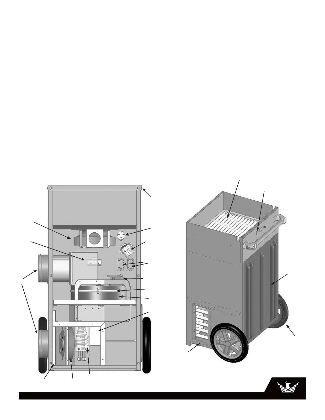
7 Service Parts List
Item Part No. Description
1 4025076 FAN, MOTORIZED IMPELLER, PROCESS AIR
2 4035235-07 CAPACITOR, RUN, 15 MFD, 370V, DRY, PROCESS AIR
3 4026784 COLLAR, SHORT 6” REACTIVATION DUCT (2 PLACES)
4 4026315 FILTER, AIR, 12 X 12 X 1, REACTIVATION AIR
5 4026798 FAN, MOTORIZED IMPELLER, REACTIVATION AIR
6 4037807 HEATER CORE, PHX D385
7 4029266 TOP COVER, DESICCANT 385
8 4026898 THERMAL OVERLOAD CUT-OUT SWITCH, PROCESS AIR
9 4035235-11 CAPACITOR, RUN, 8 MFD, DRY, REACTIVATION AIR
10 1970010 CONTROL RELAY SPST 110VAC COIL 25AMP CONTACTS
11 4026773 MOTOR, DESICCANT WHEEL
12 4026795 BELT, DRIVE, PHOENIX DESICCANT
13 4026772 WHEEL, DESICCANT
14 4037348 HEATER TUBE ASSEMBLY
15 4021475 FILTER, AIR, 16 X 20 X 2, PROCESS AIR
16 4026194 SWITCH, ROCKER, DPST, ON-OFF
17 4025043 PLATE, SKID
18 4026304 WHEEL, PU 12.00, GRAY (2 PLACES)
19 4024078 COLLAR, DUCT, WIRE, 5.75 X 12.00
1
2
3
4
9
10
11
12
15
16
17
19
5
6
13
14
7
8
18
Item Part No. Description
Not 4032315 CORD
Shown
Not 4026922 GASKET AND BELT
Shown REPLACEMENT KIT

8
USEPHOENIX.COM | 800-533-7533
Warrantor:
Therma-Stor LLC
4201 Lien Rd
Madison, WI 53704
Telephone: 1-800-533-7533
Who Is Covered: This warranty extends only to the original end-user of the Phoenix D385 dehumidifier,
and may not be assigned or transferred.
One Year Warranty: Therma-Stor LLC warrants that, for one (1) year the Phoenix D385 dehumidifier
will operate free from any defects in materials and workmanship, or Therma-Stor LLC will, at its option,
repair or replace the defective part(s), free of any charge.
End-User Responsibilities: Warranty service must be performed by a Servicer authorized by Therma-
Stor LLC. If the end-user is unable to locate or obtain warranty service from an authorized Servicer,
the end-user should call Therma-Stor LLC at the above number and ask for the Therma-Stor Service
Department., which will then arrange for covered warranty service. Warranty service will be performed
during normal working hours.
The end-user must present proof of purchase (lease) upon request, by use of the warranty card or
other reasonable and reliable means. The end-user is responsible for normal care. This warranty does
not cover any defect, malfunction, etc. resulting from misuse, abuse, lack of normal care, corrosion,
freezing, tampering, modification, unauthorized or improper repair or installation, accident, acts of
nature or any other cause beyond Therma-Stor LLC’ reasonable control.
Limitations and Exclusions: If any Phoenix D385 Dehumidifier part is repaired or replaced, the new
part shall be warranted for only the remainder of the original warranty period applicable thereto (but all
warranty periods will be extended by the period of time, if any, that the Phoenix D385 Dehumidifier is
out of service while awaiting covered warranty service).
UPON THE EXPIRATION OF THE WRITTEN WARRANTY APPLICABLE TO THE Phoenix D385
DEHUMIDIFIER OR ANY PART THEREOF, ALL OTHER WARRANTIES IMPLIED BY LAW, INCLUDING
MERCHANTABILITY AND FITNESS FOR A PARTICULAR PURPOSE, SHALL ALSO EXPIRE. ALL
WARRANTIES MADE BY THERMA-STOR LLC ARE SET FORTH HEREIN, AND NO CLAIM MAY BE MADE
AGAINST THERMA-STOR LLC BASED ON ANY ORAL WARRANTY. IN NO EVENT SHALL THERMA-STOR
LLC, IN CONNECTION WITH THE SALE, INSTALLATION, USE, REPAIR OR REPLACEMENT OF ANY Phoenix
D385 DEHUMIDIFIER OR PART THEREOF BE LIABLE UNDER ANY LEGAL THEORY FOR ANY SPECIAL,
INDIRECT OR CONSEQUENTIAL DAMAGES INCLUDING WITHOUT LIMITATION WATER DAMAGE (THE
END-USER SHOULD TAKE PRECAUTIONS AGAINST SAME), LOST PROFITS, DELAY, OR LOSS OF USE OR
DAMAGE TO ANY REAL OR PERSONAL PROPERTY.
Some states do not allow limitations on how long an implied warranty lasts, and some do not allow the
exclusion or limitation of incidental or consequential damages, so one or both of these limitation may
not apply to you.
Legal Rights: This warranty gives you specific legal rights, and you may also have other rights which vary
from state to state.
LIMITED WARRANTY
D385 | DESICCANT DEHUMIDIFIER
4201 LIEN RD. • MADISON, WI 53704