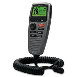
CORTEX
®
H1 HANDSET
INSTALLATION INSTRUCTIONS
Important Safety Information
WARNING
See the Important Safety and Product Information guide in the product box for product warnings and other
important information.
Failure to install this device according to these instructions could result in personal injury, damage to the vessel
or device, or poor product performance.
To avoid possible personal injury or damage to the device and vessel, disconnect the vessel's power supply
before beginning to install the device.
CAUTION
To avoid possible personal injury, always wear safety goggles, ear protection, and a dust mask when drilling,
cutting, or sanding.
NOTICE
To avoid damage to your boat, this device should be installed by a qualified marine installer. Specific knowledge
of marine electrical systems is required for proper installation.
When drilling or cutting, always check what is on the opposite side of the surface to avoid damaging the vessel.
If you are mounting the device in fiberglass, when drilling the pilot holes, use a countersink bit to drill a
clearance counterbore through only the top gel-coat layer. This will help to avoid cracking in the gel-coat layer
when the screws are tightened.
Tools and Supplies Needed
• Drill
• Drill bit suitable for drilling pilot holes in the mounting surface
• 3mm (
1
/
8
in.) drill bit suitable for drilling a cable pass-through hole in the mounting surface
• Phillips screwdriver
• 16 AWG (1.5mm²) 2-conductor electrical cable long enough to reach the bulkhead connector mounting
location from the battery
• Waterproof wire connectors
• 2 A fuse or breaker
• Marine sealant (optional)
• Plastic prying tool or small flat screwdriver
GUID-C1DEADA3-AECC-4129-A237-68550DAE4B0A v1
January 2025
Mounting Considerations
When selecting a mounting location, observe these considerations.
• You should select mounting locations for the cradle and the bulkhead connector that are close to each other,
to avoid unnecessary strain on the handset cable and connector.
• You must select a mounting location for the bulkhead connector with at least 60 mm (2
12
/
32
in.) of clearance
behind the bulkhead.
• You must select a mounting location that is within range of the Wi‑Fi
®
network used to connect to the Cortex
hub
1
.
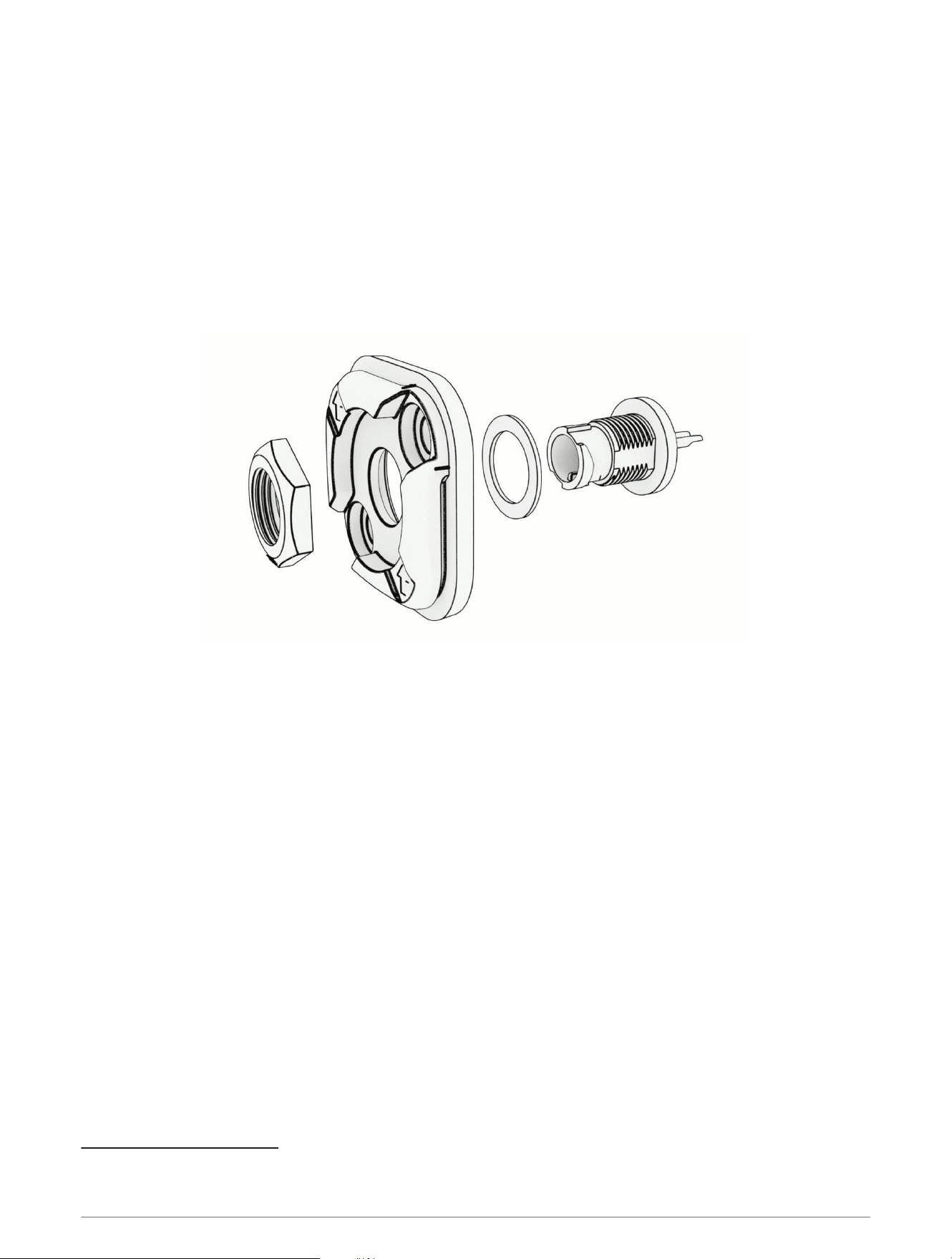
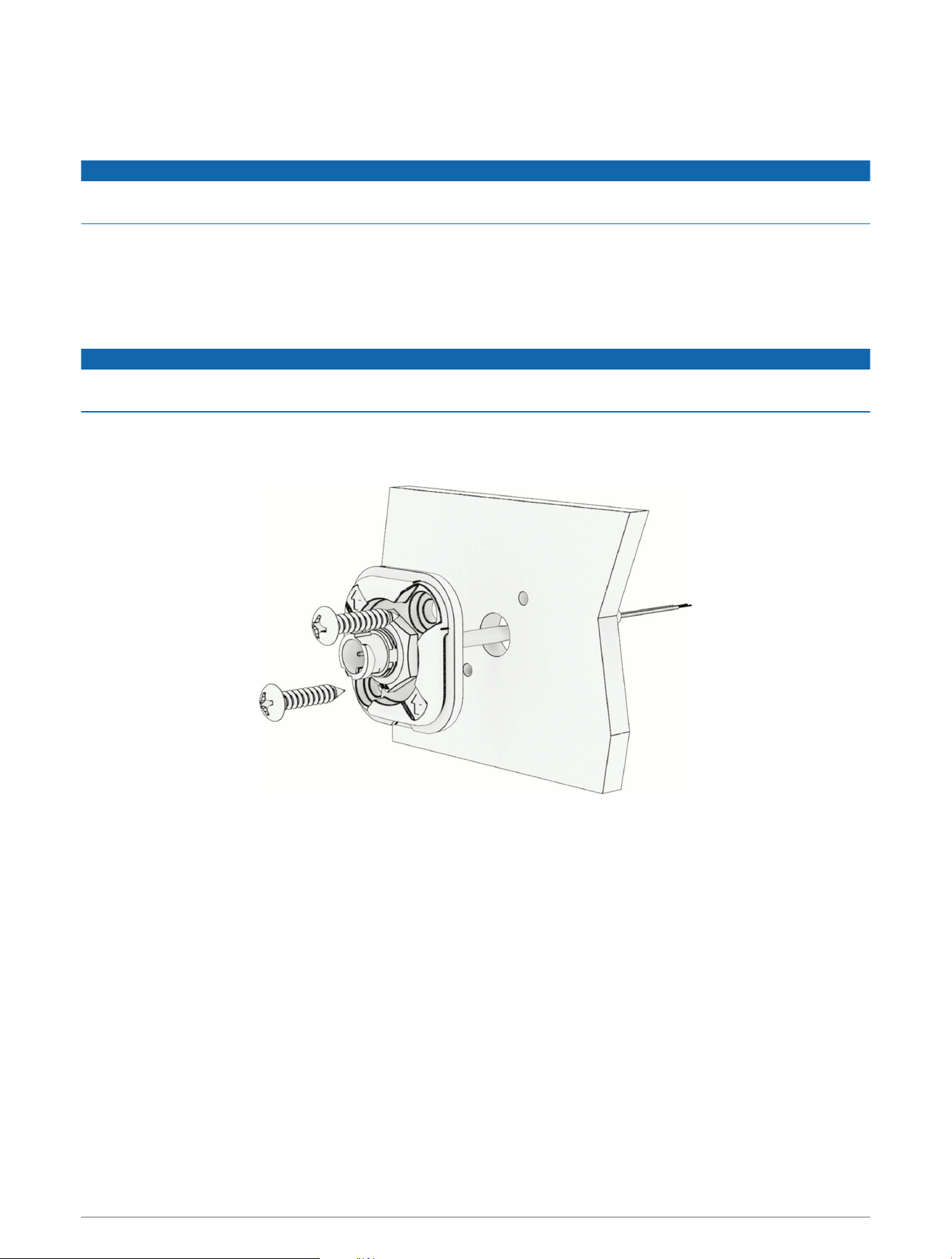
Preparing the Bulkhead Connector Mounting Surface
1 Disassemble the bulkhead connector by removing the jam nut from the connector.
2 Set aside the jam nut, the connector, and the washer.
3 Using the bulkhead connector plate as a template, mark the location of the two pilot holes and the center of
the through-hole for the power cable.
NOTE: In most cases, you should install the bulkhead connector plate with the arrows pointing up, so that the
handset cable will hang down when connected.
4 Reassemble the bulkhead connector by feeding the connector through the washer and the bulkhead
connector plate, and reinstalling the jam nut.
5 Drill the two pilot holes for the mounting screws and the through-hole for the power cable.
1
The Cortex hub can broadcast its own Wi‑Fi network or it can use the boat's Wi‑Fi network to connect to Cortex handsets and the Cortex Onboard
™
app. See the
Cortex hub Owner's Manual for more information.
2
Installing the Bulkhead Connector
Before installing the bulkhead connector, you must prepare the mounting surface (Preparing the Bulkhead
Connector Mounting Surface, page2).
NOTICE
When connecting wires, you must use waterproof connectors to protect the conductors from corrosion that can
lead to product malfunction.
1 Route a 2-conductor, 16 AWG (1.5mm
²
) marine-grade electrical cable (not included) between the mounting
location and the power supply.
2 Route the power cable through the hole you drilled into the mounting surface.
3 Connect the positive wire from the power supply to the red wire on the bulkhead connector, and the negative
wire from the power supply to the black wire on the bulkhead connector.
NOTICE
You must connect a 2A inline fuse to the positive wire, near the power supply, to properly protect the cable from
damage in case of an electrical short.
4 If the mounting location is exposed to the weather, apply marine sealant to the mounting screws and around
the cable pass-through hole, to protect the mounting surface material from moisture.
5 Place the bulkhead connector plate on the bulkhead, and secure it to the bulkhead using two screws.
NOTE: In most cases, you should install the bulkhead connector plate with the arrows pointing up, so that the
handset cable will hang down when connected.
3
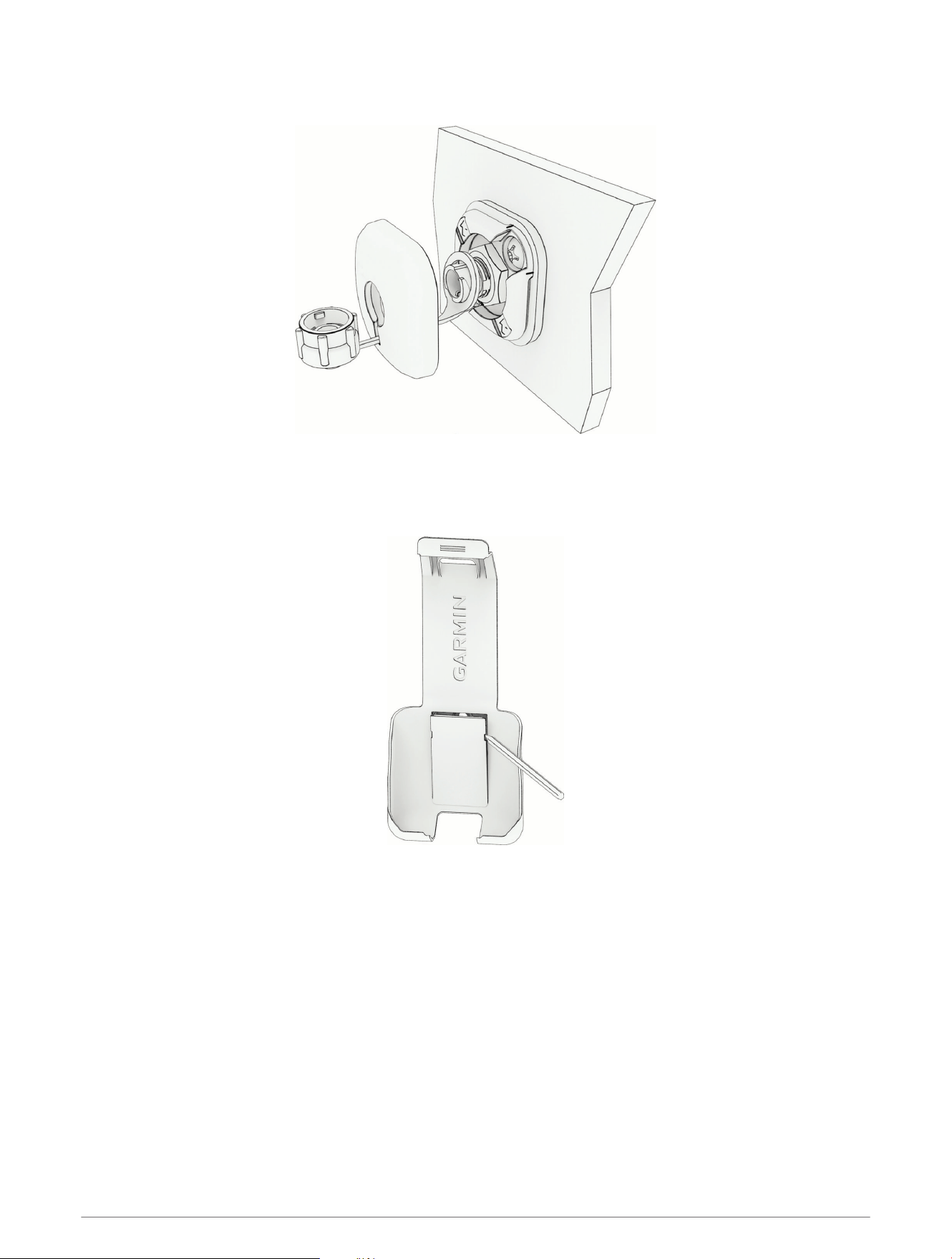
6 Feed the weather cap retaining ring through the keyhole-shaped slot in the finish plate, and place the ring
around the connector.
7 Snap the finish plate in place.
Installing the Cradle
1 Using a plastic pry tool or a small flat screwdriver, remove the cover plate from the handset cradle.
2 Place the cradle in the mounting location, and mark the three pilot holes.
3 Remove the cradle.
4 Using a drill bit suitable for the mounting surface and the mounting screws, drill the three pilot holes.
5 If the mounting location is exposed to the weather, apply marine sealant to the mounting screws, to protect
the mounting surface material from moisture.
4
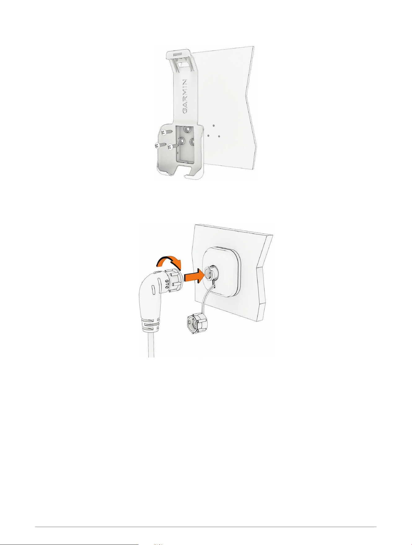
6 Secure the cradle to the mounting surface using the included screws.
7 Snap the cover plate back in place.
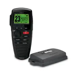
Connecting the Handset to Power
Connect the handset power cable to the bulkhead connector and tighten the locking ring.
5
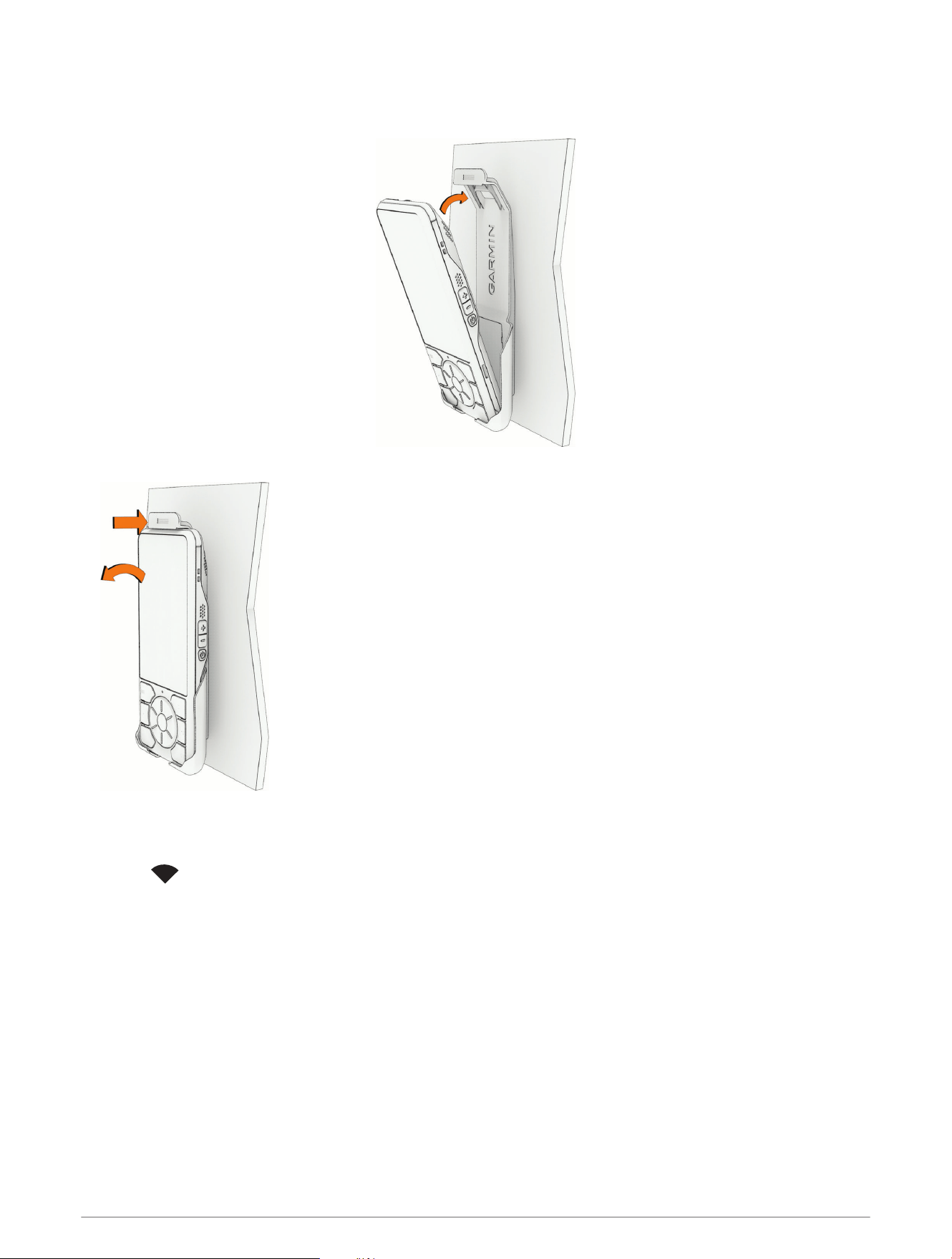
Using the Cradle
• Place the bottom of the handset in the cradle and push it back to lock it into the cradle.
• To remove the handset, push the retaining latch back to release the handset from the cradle.
Connecting the Handset to the Cortex Hub
1 Turn on the handset.
2 Select .
3 Enter the SSID and password for the Cortex hub's Wi‑Fi network.
The SSID and password can be found on the back of the Cortex hub.
4 Select Connect.
6

Specifications
Dimensions (H×W×D) 164.8 × 71.8 × 21.4mm (6.5 × 0.8 × 0.9in.)
Weight 285g (0.63lb.), including the power cable
Operating temperature range From -25° to 55°C (from -13° to 131°F)
Storage temperature range From -25° to 70°C (from -13° to 158°F)
Compass-safe distance 80cm (31.5in.)
Water rating IEC 60529 IPX8
2
Power supply 12 or 24 VDC
Maximum power 12W (1A at 12V)
Sound output 3W Class D amplifier, THD < 5% @ 85dBA
EU SAR 0,01 W/kg torso, 0,07 W/kg limb
Viewing E-label Regulatory and Compliance Information
1 Press .
2 Select Settings > Certifications.
© 2024 Garmin Ltd. or its subsidiaries
Garmin
®
, the Garmin logo and Cortex
®
are trademarks of Garmin Ltd. or its subsidiaries, registered in the USA and other countries.
2
The device withstands incidental exposure to water of up to 2m for up to 60min. For more information, go to garmin.com/waterrating.
7

© 2024 Garmin Ltd. or its subsidiaries
support.garmin.com