
© SIMPLIPHI POWER, INC.
SIMPLIPHIPOWER.COM | 805-640-6700 | BSREV202111141140
1
MODEL NO. 050000, 050001
Installaon Manual
AccESS PHI Sol-Ark
15.2 kWh, 19 kWh
AccESS PHI Sol-Ark
15.2 kWh, 19 kWh
Not for reproduction
© SIMPLIPHI POWER, INC.
SIMPLIPHIPOWER.COM | 805-640-6700 | BSREV202111141140
2
MODEL NO. 050000, 050001
SimpliPhi Your Energy
Security and Independence
and gain control of your own power.
SimpliPhi Power helps you manage your power as a personal resource.
Anytime. Anywhere. SimpliPhi energy storage optimizes integration of any
power generation source – solar, wind, generator – on or off grid, and protects
your home and mission-critical business functions from power outages and
intermittency. SimpliPhi storage technology reduces operating temperature
constraints, toxic coolants and the risk of thermal runaway. Safe lithium ferrous
phosphate (LFP). No cobalt. No toxic hazards.
SimpliPhi’s battery technology utilizes the industry’s most environmentally benign
chemistry (LFP) combined with proprietary architecture and power electronics
(BMS) to create a portfolio of high performance, scalable and enduring energy
storage solutions that provide power security, resilience and daily cycling for
savings on your utility bill – all with a 98% efficiency rate.
SimpliPhi Power offers proprietary, commercially available energy storage and
management systems that are safe, non-toxic, reliable, durable, efficient, highly
scalable, and economical over the lifetime of the PHI Battery.
Not for reproduction

© SIMPLIPHI POWER, INC.
SIMPLIPHIPOWER.COM | 805-640-6700 | BSREV202111141140
3
MODEL NO. 050000, 050001
Table of Contents
1.0 – Important Safety Informaon ................................................................................................................................................... 4
1.1 – Safety Instrucons ................................................................................................................................................................... 4
1.2 – Safety & Protecve Features................................................................................................................................................. 5
1.3 – Limitaons of Use .................................................................................................................................................................... 8
1.4 – Explosive Gas Precauons ..................................................................................................................................................... 8
1.5 – Regulatory Specicaons ....................................................................................................................................................... 8
2.0 – Product Descripon .................................................................................................................................................................... 9
2.1 – Overview ................................................................................................................................................................................... 9
2.2 – Model Numbers ....................................................................................................................................................................... 9
2.3 – Specicaons ............................................................................................................................................................................ 10
2.4 – Inside the AccESS NEMA-3R Rated Cabinet..................................................................................................................... 12
3.0 – Pre-Installaon ............................................................................................................................................................................. 13
3.1 – PHI 3.8-M Baery Performance Parameters and Sizing Calculaons ......................................................................... 13
3.2 – System Sizing for Your Installaon ....................................................................................................................................... 13
3.3 – Installaon Tools and Materials ............................................................................................................................................ 14
3.4 – Installaon Site Locaon ........................................................................................................................................................ 15
3.5 – Clearance Requirements ........................................................................................................................................................ 16
3.6 – Knock Out Locaons ............................................................................................................................................................. 17
3.7 – Pad Mounng ........................................................................................................................................................................... 17
3.8 – Wire Run Lengths ................................................................................................................................................................... 19
3.9 – Sub-panel or Transfer Switch Kit Installaon & Wiring .................................................................................................. 19
4.0 – Installaon & Wiring ................................................................................................................................................................... 20
4.1 – Basic System Conguraon Concepts ................................................................................................................................ 20
4.2 – PHI 3.8-M Baery Installaon within the AccESS ........................................................................................................... 20
4.3 – Combining Connecons ......................................................................................................................................................... 23
4.4 – Communicaons and Network Preparaon ...................................................................................................................... 25
4.5 – Wiring the AccESS ................................................................................................................................................................... 26
5.0 – Programming ................................................................................................................................................................................ 41
5.1 – Depth of Discharge ................................................................................................................................................................. 41
5.2 – Operang Parameters Per Warranty ................................................................................................................................... 41
5.3 – Conguring the Sol-Ark to a Specic Applicaon ............................................................................................................ 46
6.0 – SimpliPhi Technical Support ...................................................................................................................................................... 53
7.0 – Baery Recycling ......................................................................................................................................................................... 54
Appendix A – Sol-Ark WiFi Setup ....................................................................................................................................................... 55
Appendix B – Rapid Shutdown Compliance .................................................................................................................................... 60
Not for reproduction
© SIMPLIPHI POWER, INC.
SIMPLIPHIPOWER.COM | 805-640-6700 | BSREV202111141140
4
MODEL NO. 050000, 050001
THE ACCESS UNIT AND PHI BATTERIES CONTAINED WITHIN THE UNIT MUST BE INSTALLED
ACCORDING TO THE PROCEDURES OUTLINED IN THIS INSTALLATION MANUAL AND THE PHI
BATTERY INSTALLATION MANUAL. ALL ACCESS UNIT OPERATION MUST BE IN ACCORDANCE WITH
THE SETTINGS AND CONFIGURATION OUTLINED IN THIS MANUAL. FAILURE TO ADHERE TO EITHER
THE ACCESS INSTALLATION MANUAL OR THE PHI BATTERY INSTALLATION MANUAL WILL VOID
YOUR WARRANTY. ALL ACCESS UNITS ARE PRE-PROGRAMMED FOR BATTERY CAPACITY ORIGINALLY
INSTALLED. IF ADDITIONAL CAPACITY IS NEEDED, CONTACT YOUR ORIGINAL INSTALLER AND LOCAL
CERTIFYING BODY PRIOR TO PROCEEDING.
1.0 - Important Safety Informaon
1.1 – Safety Instrucons
1. Before using the unit, read all instrucons and cauonary markings on the unit, the PHI baeries, and all appropriate
secons of this manual.
2. PHI baeries must be fully charged before commissioning the AccESS unit (i.e. before turning on connected loads). Failure
to do so will void the Warranty.
3. Use of accessories not recommended or sold by the manufacturer may result in a risk of re, electric shock, or injury to
persons and will void the Warranty.
4. Verify system sengs are in compliance with the Baery Warranty and Baery Installaon Manual (which take
precedence). Violang Warranty condions specied in these documents will void the Warranty on the PHI baeries.
5. Consult the Integraon Guide for Sol-Ark equipment sengs as well as relevant warnings and noces. All Integraon
Guides are posted on SimpliPhi’s Product Documentaon web page (hps://simpliphipower.com/product-documentaon/).
Violang Warranty condions specied in the Sol-Ark Integraon Guide will void the Warranty on the enre AccESS unit,
not just the SolArk equipment.
6. Each AccESS system contains PHI 3.8 baeries. Although each PHI 3.8 baery contains both a circuit breaker and an
internal BMS with circuitry that protects the PHI 3.8 baery cells from overcharge, over-discharge and excessive load
amperage, the PHI baeries must always be installed with appropriate Balance of System equipment sengs and power
electronics to protect the PHI 3.8 from open solar PV voltage and other high voltage charging sources. Do not aempt to
replace exisng power electronics without SimpliPhi’s wrien approval. Failure to adhere to installaon protocol will void
the Warranty.
7. Verify polarity at all connecons with a standard voltmeter before:
A. Energizing the system and
B. Turning the PHI 3.8 circuit breaker’s “ON/OFF” switch to the “ON” posion. Reverse polarity at the PHI 3.8 baery
terminals will void the Warranty and destroy the PHI baeries.
8. PHI baeries pose some risk of shock or sparking during the installaon and inial wiring and connecon process. This is
consistent with all other baery-based storage formats. Be sure to turn the built-in circuit breaker to the “OFF” posion to
minimize the risk of shock or sparks during the installaon and commissioning of the system.
9. To avoid a risk of re and electric shock, make sure that exisng wiring is in good condion and that wire is not undersized.
Do not operate the AccESS unit with damaged or substandard wiring. This will void the Warranty.
10. Do not operate the AccESS unit if it has been damaged in any way during shipping or otherwise.
Not for reproduction
© SIMPLIPHI POWER, INC.
SIMPLIPHIPOWER.COM | 805-640-6700 | BSREV202111141140
5
MODEL NO. 050000, 050001
11. Only use a SimpliPhi approved LFP baery charger if ancillary charging is required before installaon, tesng or
troubleshoong. Failure to use a SimpliPhi approved LFP baery charger will damage the PHI 3.8 baery and void the
Warranty. Refer to the PHI 3.8 Manual for details regarding SimpliPhi-approved ancillary charging equipment.
12. To reduce the chance of short-circuits, always use insulated tools when installing or working with this equipment.
13. Remove personal metal items such as rings, bracelets, necklaces, and watches when working with electrical equipment.
14. The AccESS unit does not have any user-serviceable parts. Do not disassemble the inverter except where noted for
connecng wiring and cabling. See your Warranty for instrucons on obtaining service. Aempng to service the
components inside the AccESS unit yourself may result in a risk of electrical shock or re and void the Warranty. Internal
capacitors remain charged aer all power is disconnected – wait 10 minutes before servicing.
15. To reduce the risk of electrical shock, disconnect both AC and DC power from the AccESS unit before aempng any
maintenance or cleaning or working on any components connected to the inverter.
1.2 – Safety & Protecve Features
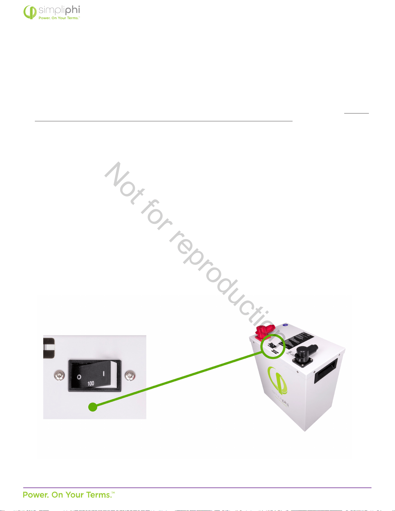
1.2.1 – Baery Breaker
All PHI 3.8 baeries within the AccESS unit are outed with an hydraulic/magnec circuit breaker which will show a
white base when tripped. This breaker increases safety during shipping and installaons and allows the PHI 3.8 baery
to eecvely be turned “OFF” or “ON.” The breaker works in conjuncon with the built-in baery management system
(BMS) and creates addional safety, eciency and funconality to the overall power storage system.
Figure 1 - PHI 3.8 kWh 51.2Vnom Circuit Breaker
Not for reproduction
© SIMPLIPHI POWER, INC.
SIMPLIPHIPOWER.COM | 805-640-6700 | BSREV202111141140
6
MODEL NO. 050000, 050001
PHI baeries pose some risk of shock or sparking during the installaon and inial wiring and connecon process. This is
consistent with all other baery-based storage formats. Be sure to turn the built-in circuit breaker to the “OFF” posion
to minimize the risk of shock or sparks during the installaon and commissioning of the system. Use of insulated gloves,
clothing and footwear is always recommended when working in close proximity to electrical devices. Cover, restrain or
remove jewelry or conducve objects (metal bracelets, rings, belt buckles, metal snaps, zippers, etc.) when working with
any electrical or mechanical device. Cover or restrain long hair and loose clothing when working with any electrical or
mechanical device.
PHI baeries do not vent any harmful gasses, and do not require special venlaon or cooling.
PHI baeries are not capable of thermal runaway. As with any baery, if the cells are severely damaged due to physical
abuse incurred outside of warranted specicaons, it can cause electrolyte leakage and other failures. The electrolyte
can be ignited by an open ame. However, unlike other lithium ion baeries (e.g. LCO, NCM, and NCA), the PHI baeries’
electrolyte and other material components generate a limited amount of heat.
1.2.2 – Charging at Temperatures Below Freezing
It is important to take necessary steps to determine the temperature of the PHI 3.8 baery prior to charging the baery, as
the baery may otherwise be adversely impacted.
CAUTION: Circuit Breakers, Disconnects and Fuses should be employed throughout several points of a
power storage and generaon installaon to eecvely isolate and protect all components of the system
to safeguard against faults, short circuits, polarity reversals or a failure of any component in the overall
system. Fuses, breakers, wiring rangs and values should be determined by established standards and
evaluated by cered electricians, licensed installers, and regional code authories. Although each PHI 3.8
baery contains both a circuit breaker and an internal BMS with circuitry that protects the Lithium Ferrous
Phosphate cells from overcharge, over-discharge and excessive load amperage, the PHI baeries must always
be installed with a charge controller and the appropriate sengs to protect the PHI 3.8 baery from open PV
voltage and other high voltage charging sources.
The PHI 3.8 Baery Management System (BMS) and built-in circuit breaker alone will not protect the PHI
baeries from extreme electrical condions. Failure to adhere to installaon protocol will void the Warranty.
CAUTION: Verify polarity at all connecons with a standard voltmeter before 1) energizing the system
and 2) turning the PHI 3.8 circuit breaker’s “ON/OFF” switch to the “ON” posion. Reverse polarity at the
baery terminals will void the Warranty and destroy the PHI baeries.
CAUTION: Do not aempt to charge the PHI 3.8 baery below 32° F (0° C). Although cold temperatures do
not harm PHI baeries, aempts to charge at subfreezing temperatures can adversely aect SOH and cycle
life, and will void the Warranty. If the PHI 3.8 baery must be charged below 32° F (0° C), the rate of charge
must be at no more than 5% of the PHI 3.8 baery’s rated capacity (C/20).
MISE EN GARDE: Ne pas charger la Baerie PHI en dessous de 0° C (32° F). Tout chargement à des
températures de congélaon peuvent nuire à l’état de santé et la durée de vie de la baerie, et Annuleront la
Garane. Dans le cas ou la Baerie PHI doit être chargée en dessous de 0° C (32° F), le taux de charge ne doit
pas dépasser 5 % de la capacité nominale de la Baerie PHI (C/20).
Not for reproduction
© SIMPLIPHI POWER, INC.
SIMPLIPHIPOWER.COM | 805-640-6700 | BSREV202111141140
7
MODEL NO. 050000, 050001
1.2.3 – Baery Management System (BMS)
The PHI 3.8 baeries within the AccESS unit are manufactured ulizing Lithium Ferrous Phosphate (LFP) cells, which are
produced under exclusive patented licensed technologies, as well as proprietary materials, architecture, manufacturing
processes and baery management system (BMS). This assures the highest grade and quality, longest cycle-life, greatest
eciency and freedom from material impuries, toxicity and hazardous risk.
Each PHI 3.8 baery within the AccESS unit contains circuitry that protects the Lithium Ferrous Phosphate cells from
overcharge, over-discharge and excessive load amperage. If the values specied are exceeded, the protecve circuitry will
shut down the ow of electricity to/from the PHI baeries. In some cases, this will result in the need to manually turn the
baeries and inverter back on. Oen, inverter system sengs will be saved within the inverter memory storage and will not
need to be reset. This is not an absolute standard but is common amongst most inverter/chargers and should be ancipated
if the PHI baeries go into a state of selfprotecon and shut down the ow of electricity.
1.2.4 – PHI 3.8 Baery Connecon Terminals
The PHI 3.8 baeries are equipped with two 3/8’’ threaded studs with a lock washer and nut. The red colored high
temperature molded insert connecon is for the posive lead. The black colored high temperature insert connecon is for
the negave lead.
CAUTION: Do not aempt to loosen the large brass nut at the base of the terminals. This will void the
Warranty.
MISE EN GARDE: Ne pas desserrer le gros écrou en laiton à la base des bornes; cela endommagerait la
Baerie PHI et Annulerait la Garane.
CAUTION: Only use a SimpliPhi approved LFP charger if ancillary charging is required before installaon,
tesng or troubleshoong. Failure to use a SimpliPhi approved LFP charger will damage the PHI 3.8 baery
and void the Warranty. Refer to the PHI 3.8 Manual for details regarding SimpliPhi-approved ancillary
charging equipment.
CAUTION: While the BMS and internal circuit breaker protect the PHI baery from extreme electrical
scenarios, neither will prevent the PHI baery from operang outside the recommended operang
parameters. Rely on Balance of System equipment programming to operate the baery according to
recommended parameters, as outlined in the Sol-Ark Integraon Guide.
Not for reproduction
© SIMPLIPHI POWER, INC.
SIMPLIPHIPOWER.COM | 805-640-6700 | BSREV202111141140
8
MODEL NO. 050000, 050001
CAUTION: Do not reverse polarity. It will void the Warranty. Use a voltmeter to check polarity before
connecng terminals.
MISE EN GARDE: Ne pas inverser la polarité. Inverser la polarité Annulera la Garane.
Water Resistant Cable Boots are also included and will be in place when your units arrive. The boots are to be placed over
the cable terminaons and will stretch to form a water-resistant seal around the base of the molded inserts and terminal
connecons.
1.3 – Limitaons of Use
The Sol-Ark equipment built into the SimpliPhi Power AccESS is not intended for use in connecon with life support systems or
other medical equipment or devices.
1.4 – Explosive Gas Precauons
This equipment is not ignion protected. To prevent re or explosion, do not install this product in locaons that require ignion-
protected equipment. This includes any conned space containing vented baeries, or ammable chemicals such as, natural
gas (NG), liquid petroleum gas (LPG) or gasoline (Benzine/Petrol). Do not install in a conned space with machinery powered
by ammable chemicals, or storage tanks, ngs, or other connecons between components of fuel or ammable chemical
systems.
1.5 – Regulatory Specicaons
Sol-Ark equipment has been tested and found to comply with the following:
• Electronics cered safety by SGS labs to NEC and UL specicaons: NEC 690.4B & NEC 705.4/6.
• Grid interacvity requirements UL1741-2010/2018, IEEE1547a-2003/2014, FCC 15 class B, UL1741SA, UL9540, CA
Rule 21 and HECO Rule 14H.
These standards provide regulaon for acceptable output voltage ranges, acceptable output frequency and an-islanding
performance.
Not for reproduction

© SIMPLIPHI POWER, INC.
SIMPLIPHIPOWER.COM | 805-640-6700 | BSREV202111141140
9
MODEL NO. 050000, 050001
2.0 – Product Descripon
2.1 – Overview
The SimpliPhi Sol-Ark AccESS oers industry leading renewable energy storage technology to provide energy security and
power resiliency in a pre-assembled, pre-programmed system that is suitable for installaon inside and outside. The AccESS
serves all of the common residenal scale renewable energy applicaons: O-Grid and Grid-Tied with Baery Back Up (in
both AC Coupled and DC Coupled system conguraons), and Self Consumpon – with Zero Export and Time Of Use (TOU)
arbitrage for ulity charge reducon (in DC Coupled system conguraons only).
2.2 – Model Numbers
SimpliPhi oers the Sol-Ark AccESS unit in several variaons for residenal use:
• A-4PHI-SA: one (1) AccESS cabinet that include one (1) Sol-Ark-12K inverter with integrated dual MPPT charge
controllers, four (4) PHI 3.8 core power baeries contained within the cabinet, with a Maximum Rated Capacity of
15.48 kWh.
• A-5PHI-SA: one (1) AccESS cabinet that include one (1) Sol-Ark-12K inverter with integrated dual MPPT charge
controllers, ve (5) PHI 3.8 core power baeries contained within the cabinet, with a Maximum Rated Capacity of 19.35
kWh.
• BOSS.6-R: (Oponal Conguraon): Sol-Ark 12K mounted externally to enclosure with a BOSS.6 cabinet housing either
four (4) or ve (5) PHI 3.8 core power baeries contained within the cabinet, with a Maximum Rated Capacity of 15.48
kWh or 19.35 kWh respecvely.
Not for reproduction
© SIMPLIPHI POWER, INC.
SIMPLIPHIPOWER.COM | 805-640-6700 | BSREV202111141140
10
MODEL NO. 050000, 050001
2.3 – Specicaons
Please review Tables 1.0 and 2.0 below for Sol-Ark AccESS unit specicaons, including physical dimensions, warranty period,
and technical data.
Table 1.0 – Sol-Ark AccESS Specicaons for Each Unit Note: Inverter power will be derated at 45° Celsius (113° F).
Specicaons
General
Dimensions
29.5” W x 76”H (w/feet) x 20” D /
75 cm W x 193 cm H x 51 cm D
Weight 600 lbs. (270 kg.) w/o baeries
Enclosure Rang NEMA 3R Outdoor Rated
Operang Temperature -4°F to 122°F (-20°C to 50°C)
Mounng Free-standing or Pad-mounted
Enclosure Warranty Period 2 years
Cercaons
UL1741SA Rule 21, HECO Rule 14H, PREPA approved and Rapid Shutdown compliant,
UL9540, Included baeries ETL cered and cered to UL 1973
Inverter
Sol-Ark Sol-Ark-12K
Applicaon On or O-Grid
AC Connecons
1 Bi-Direconal Grid Port (63A double-pole), 1 UPS Load Output (63A double-pole)
1 Bi-Direconal Generator Port (50A double-pole); can be used for Smart Loads output
Output Frequency (selectable) 60 Hz or 50 Hz (50 Hz available upon request)
Output Voltage L-N: 120VAC; L-L: 240VAC │ L-L: 208VAC (2/3 phases) │ 230VAC
O-Grid Output Power 9 kW Connuous
On-Grid Output Power 15.12 kW Connuous (pass-through)
Solar PV Connuous Power
Delivered to Baery & AC
Output
12 kW | To Grid: 9kW per Sol-Ark 12K MAX Connuous Baery Power
Max Baery Charging
Current
185 ADC
CEC Eciency 96.5% (97.5% Peak)
Standard Warranty Period 10 years
Not for reproduction
© SIMPLIPHI POWER, INC.
SIMPLIPHIPOWER.COM | 805-640-6700 | BSREV202111141140
11
MODEL NO. 050000, 050001
Specicaons
Other Features
EMP hardened upon request (against Nuclear EMP and Solar Flare) does not include
baeries Smart Load capabilies (2 x CTs included)
Solar PV
DC CoupledDC Coupled
Sol-Ark Dual MPPT 1 - 4 PV String Inputs (2 max per MPPT)
Max Connected PV Power 13 kW (12 kW max simultaneous ulizaon)
Min PV Array Starng Voltage 125 VDC
Max Open Circuit PV Array
Voltage
500 Voc per PV String
MPPT Voltage Range 150 – 425 VDC
Max Array Short Circuit
Current
25A per MPPT
Max Array Operang Current 20A per MPPT
AC Coupled
Max AC Coupled Input 9.6 kW (string or micro-inverters)
DC & AC Coupled
Best Combined Input
Combinaon
3 kW AC + 13 kW DC
Good Combined Input
Combinaon
5 kW AC + 11 kW DC
OK Combined Input
Combinaon
8 kW AC + 8 kW DC
Other Features
Internet Connected
(Computer or Phone App)
PowerView ES Monitor and Programming
Automac Generator Start Two-wire automac generator start
Baeries
Max Rated Unit kWh Capacity
@ C/2
4 Baery: 15.48 kWh | 5 Baery: 19.35 kWh
Usable Unit kWh Capacity @
80% DoD
4 Baery: 12.38 kWh | 5 Baery: 15.48 kWh
Max Combined Output Power 4 Baery: 7.68 kW DC | 5 Baery: 9.6 kWDC
Max Combined Charge
Current
Limited by the Sol-Ark to 185A
Charge Temperature 32°F to 120°F (0°C to 49°C)
Discharge Temperature -4°F to 140°F (-20°C to 60°C)
Depth of Discharge Up to 100% DoD
Cycle Life 10,000+ cycles (@ 80% DoD)
Note: Inverter power will be derated at 45° Celsius (113° F).
Not for reproduction
© SIMPLIPHI POWER, INC.
SIMPLIPHIPOWER.COM | 805-640-6700 | BSREV202111141140
12
MODEL NO. 050000, 050001
2.4 Inside the AccESS NEMA 3R Rated Cabinet
The AccESS system is enclosed within a NEMA-3R rated cabinet. Within, the internal layout provides easy access to clearly
labeled wiring points and includes the necessary overcurrent devices, breakers and disconnects. The heart of the AccESS is the
SimpliPhi Power PHI 3.8 kWh 51.2Vnom energy storage modules. Addional storage capacity can be achieved by adding another
BOSS.6 in parallel, side by side, with 4 or 5 of the PHI 3.8 kWh 51.2Vnom baeries with a Maximum Rated Capacity of 15.48
kWh and 19.35 kWh respecvely.
Addional Sol-Ark equipment features also include automac generator start, remote system monitoring (in the case of both
AccESS Sol-Ark models) and remote system.
2.4.1 –AccESS Core Components
The core components within the AccESS unit include the below listed products. See Figures 2.0 & 3.0 for detail.
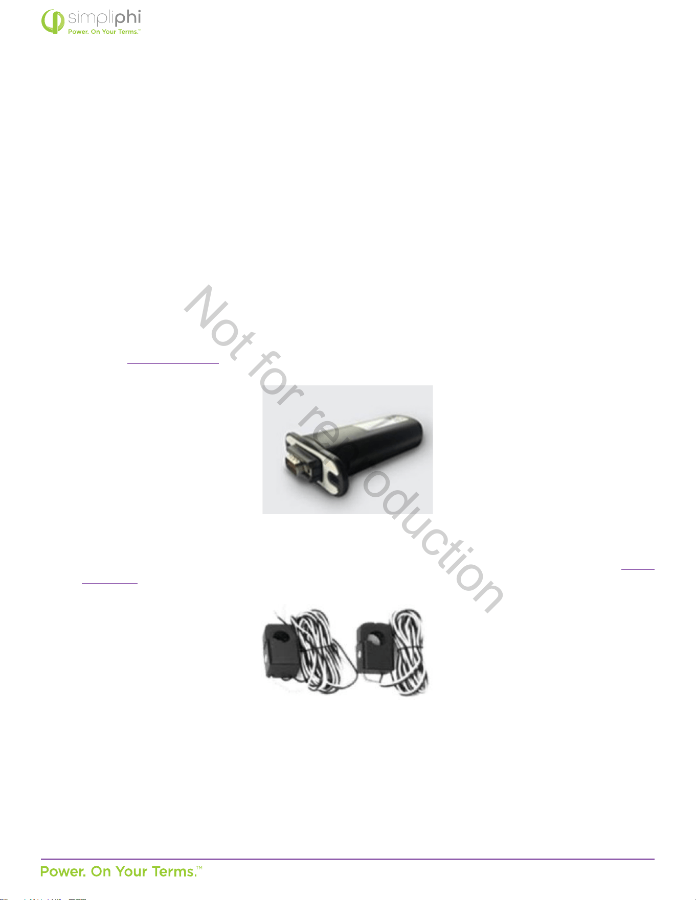
Sol-Ark-12K (manual linked here), includes:
• Solar Panel MC4 Connector Tool
• WiFi Plug
• 2 Limiter Sensors (10’ long wires included extendable up to 50’ upon direct request to Sol-Ark: 972-575-8875, sales@
sol-ark.com)
Not for reproduction

© SIMPLIPHI POWER, INC.
SIMPLIPHIPOWER.COM | 805-640-6700 | BSREV202111141140
13
MODEL NO. 050000, 050001
3.0 – Pre-Installaon
The informaon within this secon covers pre-installaon procedures & consideraons, namely, PHI 3.8 baery performance
parameters to be aware of during the design process, guidance on system sizing, as well as installaon site requirements and pad
mounng.
3.1 – PHI 3.8 Baery Performance Parameters and Sizing Calculaons
The PHI 3.8 baeries within the Sol-Ark AccESS are designed to operate at a connuous discharge rate of 1.92 kWDC each,
across a large operang temperature range, as seen in Table 1.0 above. The SimpliPhi AccESS does not require an increase
in sizing nor any special compensaons when determining the size of the energy storage and management system under the
circumstances and condions seen in Table 1.0 above. Each AccESS unit comes pre-programmed to maximize the performance
of the PHI 3.8 baery bank. Sengs are password protected and require access to the lockout password by a qualied installer
for modicaon.
PHI 3.8 baeries within the AccESS unit do not need to be de-rated unless running connuously at more than 90% capacity, at
temperatures below 0° C, or above 45° C. To achieve higher, warraned cycles of 10,000, the PHI 3.8 baeries are operated at
80% maximum Depth of Discharge (DOD). The AccESS comes preprogrammed for 80% DOD. Please contact SimpliPhi Power
Technical Support if alternave sengs are desired. Please also refer to operang temperatures and inverter sengs in this
Manual’s Programming secon.
3.1.1 – Design Parameters: Maximum Sizing Guidelines
Below are the maximum sizing guidelines for installaons of the AccESS:
• Maximum AC Grid input / output OCPD = 60 A double-pole
• Maximum DC coupled PV array = 13 kWDC (per Sol-Ark-12K)
• Maximum AC coupled PV array = 9.6 kWAC (per Sol-Ark-12K)
3.2 – System Sizing for Your Installaon
The number of PHI 3.8 baeries within the AccESS unit(s) should be specied in terms of total rated storage capacity and
instantaneous power rang before the inial installaon based on the goals and objecves of the project. All PHI 3.8 baeries
are balanced during nal producon and tesng stages. Following proper wiring guidelines ensures that a system will not require
any manual balancing processes.
Not for reproduction
© SIMPLIPHI POWER, INC.
SIMPLIPHIPOWER.COM | 805-640-6700 | BSREV202111141140
14
MODEL NO. 050000, 050001
3.3 – Installaon Tools and Materials
• Digital Mul Meter
• AC/DC Clamp-On Current Meter
• Wire Stripper
• Impact Driver
• Masonry Bolts
CAUTION: Do not combine PHI 3.8 baeries with other brands or chemistries.
CAUTION: Do not mix PHI 3.8 baeries from dierent installaons, clients or job sites.
MISE EN GARDE: Ne pas associer les Baeries PHI avec d’autres marques et/ ou autres produits chimiques.
Ne pas mélanger les Baeries PHI provenant de diérentes installaons, diérents clients ou diérents
sitesde travail. L’un ou l’autre de ces mélanges Annulera la Garane.
Not for reproduction
© SIMPLIPHI POWER, INC.
SIMPLIPHIPOWER.COM | 805-640-6700 | BSREV202111141140
15
MODEL NO. 050000, 050001
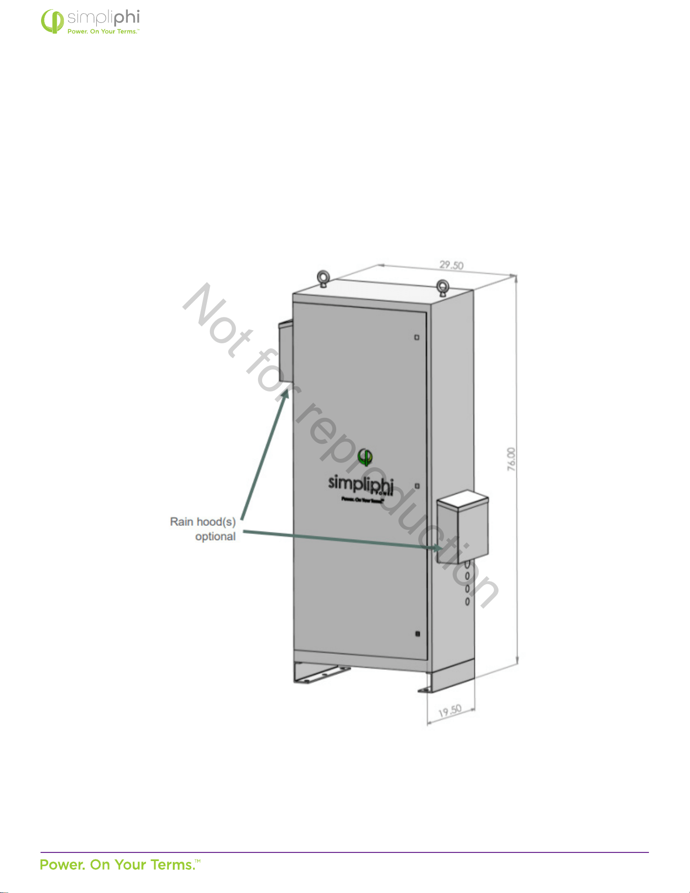
3.4 – Installaon Site Locaon
The AccESS may be installed indoors, such as a garage, or outdoors mounted onto a concrete pad. The cabinet is rated for
NEMA-3R use. Please see Figure 3.0 below for physical AccESS dimensions, as this may impact the site locaon.
Figure 3.0 – AccESS Unit Dimensions
Not for reproduction
© SIMPLIPHI POWER, INC.
SIMPLIPHIPOWER.COM | 805-640-6700 | BSREV202111141140
16
MODEL NO. 050000, 050001
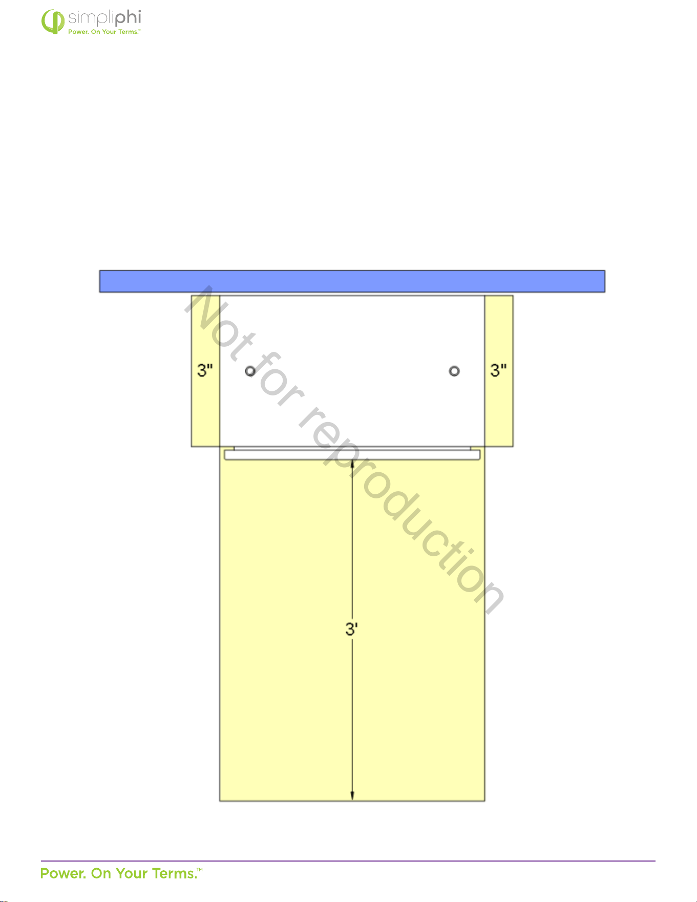
3.5 – Clearance Requirements
The AccESS should be installed with 3-inch (7.62 cm) clearance to the sides and 3 feet (0.91 m) clearance to the front to allow for
the cabinet door to be opened during installaon. Please see Figure 4.0 for details. All installaons should comply with local code
requirements and/or the local AHJ, which may exceed the requirements shown.
Figure 4.0 – AccESS Unit Clearances
Not for reproduction
© SIMPLIPHI POWER, INC.
SIMPLIPHIPOWER.COM | 805-640-6700 | BSREV202111141140
17
MODEL NO. 050000, 050001
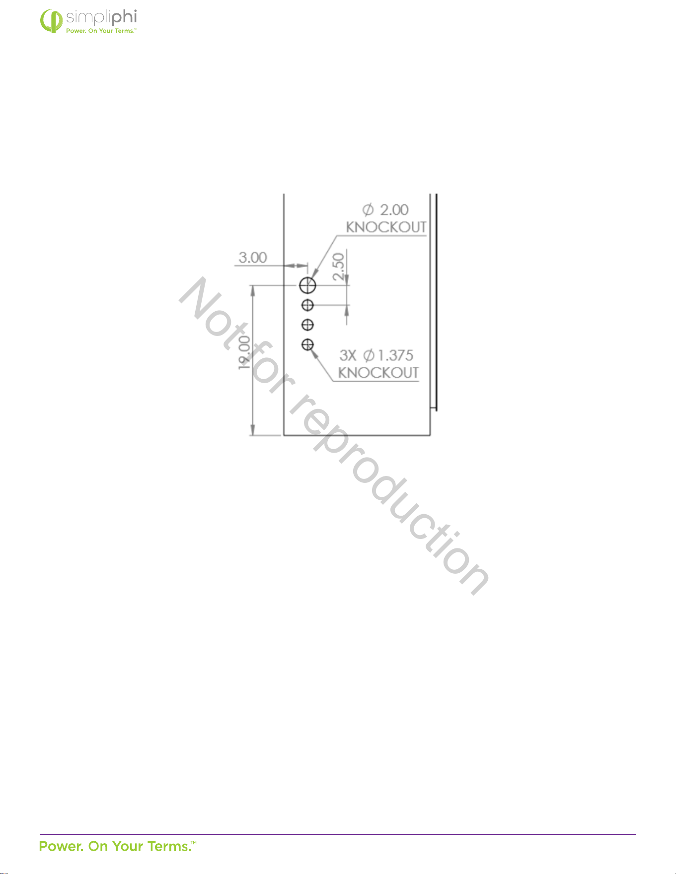
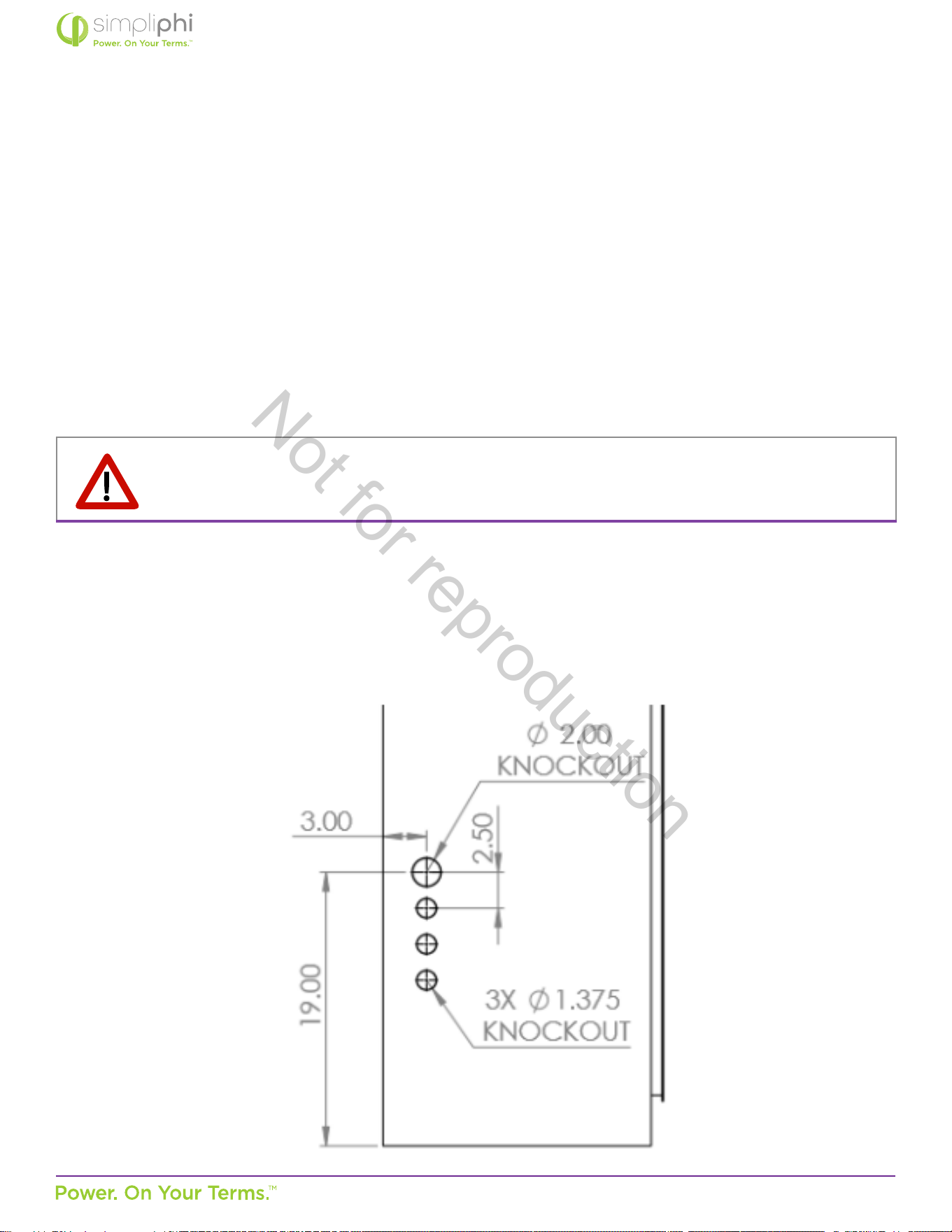
3.6 – Knock Out Locaons
Three 1.375-inch OD knockouts and one 2-inch OD knockout are located on both sides of the AccESS cabinet. They can be used
for AC or DC inputs. Not all knockouts must be used.
Figure 5.0 – AccESS Cabinet Knockouts (sides)
3.7 – Pad Mounng
3.7.1 – Pad Requirements
The AccESS must be installed and secured on level concrete. For a pre-cast concrete pad, a 4” minimum thickness is
required. The pad should be 3” wider than the AccESS on all sides (34” x 22” x 4”).
The AccESS is not suited for wall mounng. Any aempt to wall mount the AccESS unit will Void the Warranty.
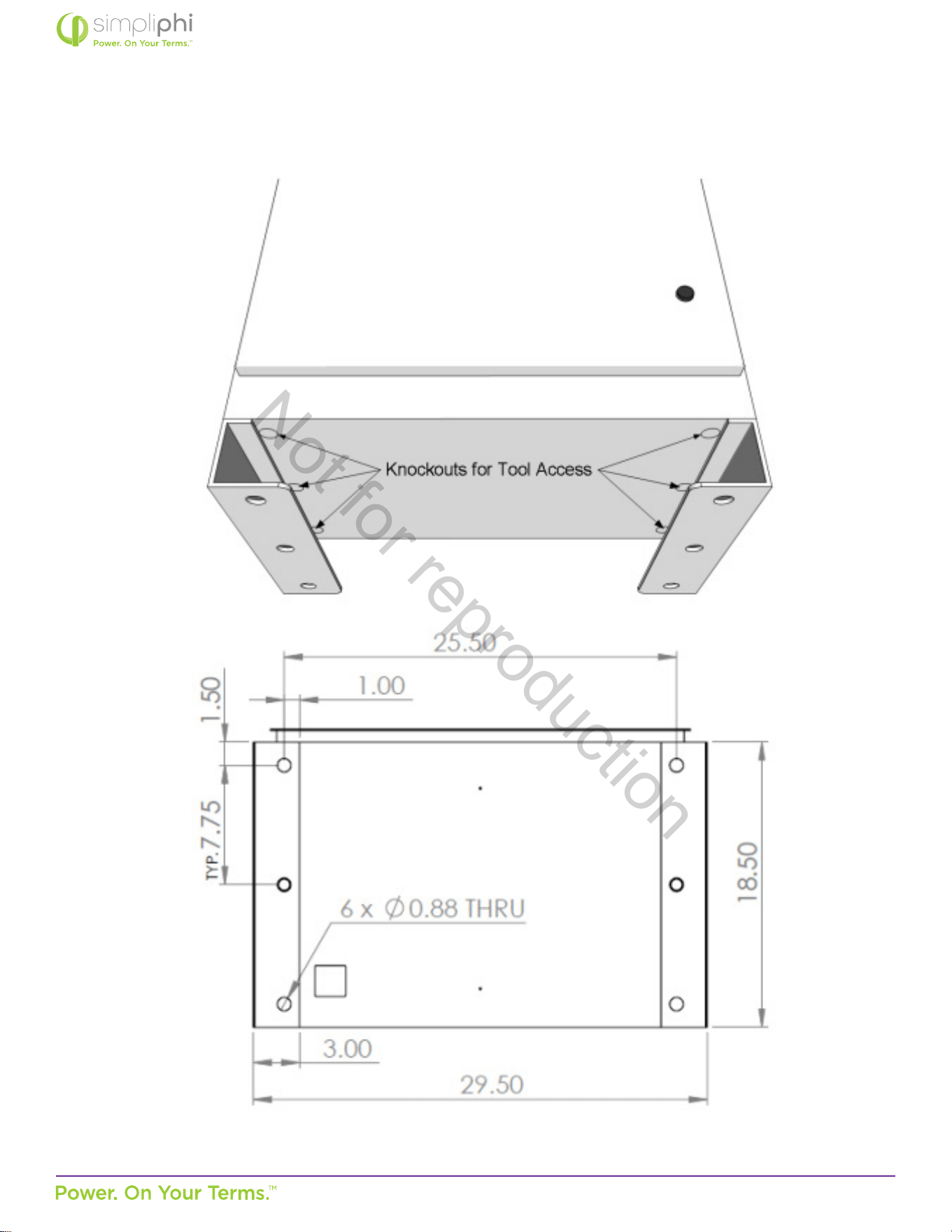
3.7.2 – Pad Mounng the SimpliPhi AccESS
Six 1-inch knockouts are located in the base of the AccESS for tool accessibility when mounng the AccESS to the concrete
pad. Cover knockout holes with sealing tape aer pad mount installaon, and prior to installing the PHI 3.8 Baeries into
the base of the cabinet. Not all knockouts have to be used, depending on the dierent assets built into the AccESS system to
meet the customer’s needs. Any aempt to wall mount the AccESS unit will void the Warranty.
Secure the AccESS to the concrete with concrete anchors, such as threaded rods, masonry bolts, or carriage bolts, minimum
½” diameter. Exisng concrete oors in the garage or other areas are adequate “mounng pads” if the thickness meets the 4”
minimum thickness. See Figure 5.0 for details.
Not for reproduction
© SIMPLIPHI POWER, INC.
SIMPLIPHIPOWER.COM | 805-640-6700 | BSREV202111141140
18
MODEL NO. 050000, 050001
Figure 6.0 – AccESS Cabinet Knockouts (boom)
Not for reproduction
© SIMPLIPHI POWER, INC.
SIMPLIPHIPOWER.COM | 805-640-6700 | BSREV202111141140
19
MODEL NO. 050000, 050001
3.8 – Wire Run Lengths
Two limiter sensors are included with the AccESS Sol-Ark. The limiter sensor wires are 10 feet long, and are extendable up to 50
feet using equipment from Sol-Ark (contact Sol-Ark directly at 972-575-8875; [email protected]). Consider this distance when
deciding the Sol-Ark AccESS unit’s locaon relave to the home’s main breaker panel.
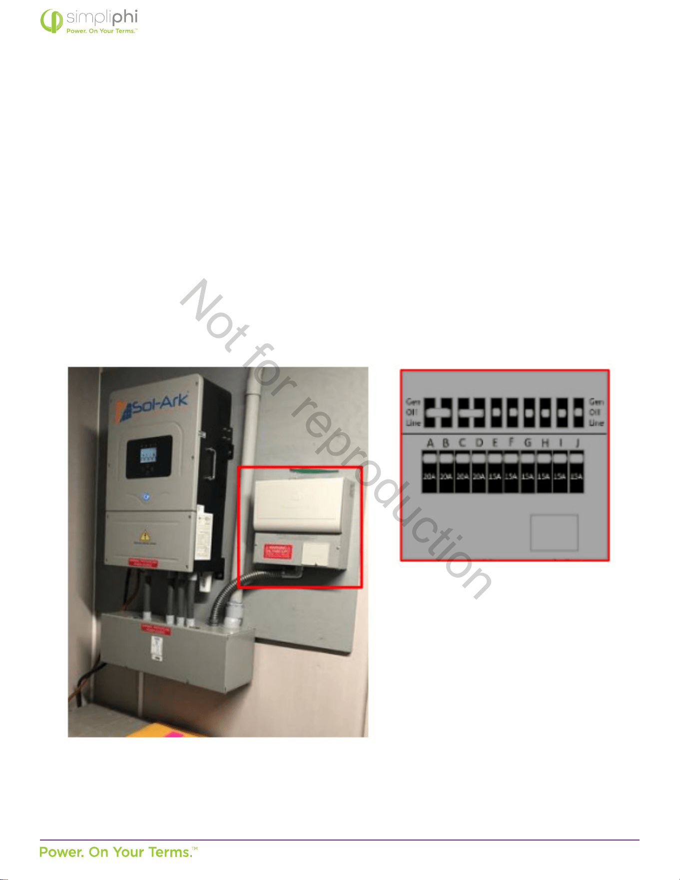
3.9 – Sub-panel or Transfer Switch Kit Installaon & Wiring
All AccESS Sol-Ark systems must incorporate either an Essenal Loads sub-panel or the 10-circuit transfer switch kit available
directly from Sol-Ark (see Figure 7.0). In the case of o-grid systems, all the home’s loads are on the Essenal Loads panel,
thereby making the Essenal Loads panel the main house breaker panel. Any distance is permissible between the AccESS Sol-Ark
and the Essenal Loads panel or Sol-Ark transfer switch kit, provided wire sizing and voltage drop is in accordance with local
codes.
Figure 7.0 – Transfer Switch Kit
Not for reproduction

© SIMPLIPHI POWER, INC.
SIMPLIPHIPOWER.COM | 805-640-6700 | BSREV202111141140
20
MODEL NO. 050000, 050001
Prior to the AccESS Sol-Ark’s installaon, determine which of the home’s circuits will be located either on the Essenal Loads
panel or the Sol-Ark transfer switch kit. Consider the following:
A. The Sol-Ark’s Load Output is protected by a 63 Amp double-pole breaker.
• When grid/generator-connected, the maximum connuous power the Sol-Ark can deliver to the Essenal Loads panel is
63 Amps at 240VAC (15.12 kWAC pass-through).
• When o-grid, the maximum power the Sol-Ark can deliver to the Essenal Loads panel (also considered the main house
breaker panel in an o-grid applicaon) is 37.5 Amps connuous at 240VAC (9.0 kWAC) and 67 Amps peak at 240VAC
(16.08 kWAC) for 10 seconds.
B. The Sol-Ark transfer switch kit (if used instead of an Essenal Loads panel) can house a maximum of 10 circuits, all of
which must use non-GFI breakers. Contact Sol-Ark (972-575-8875, [email protected]) for transfer switch kit purchase
and installaon instrucons; It is not included in the AccESS Sol-Ark.
4.0 – Installaon & Wiring
This secon covers how to install the PHI 3.8 baeries within the AccESS unit, torque values, communicaons and network
preparaon and how to wire the AccESS unit. It also provides guidance on how to install oponal AccESS unit components/
accessories.
4.1 – Basic System Conguraon Concepts
Safe and reliable installaon requires trained and cered technicians. The following discussion is a basic primer. Due to the
variety of systems and components in the eld, all possible scenarios are not covered. This is not the purpose of this secon of
the manual. Refer to professional installers regarding your system and its components and specicaons. We encourage you or
your installer to contact us with any specic quesons for technical support. We are commied to working with you and your
installaon team to achieve a safe, reliable storage system that will provide years of maintenance free service.
4.2 – PHI 3.8 Baery Installaon within the AccESS
1. Mount the AccESS unit on level concrete.
2. Make sure all PHI baery module circuit breakers are in the OFF posion. Prepare the baery modules for
installaon by removing all plasc terminal covers, 11/16” stainless steel hex nuts and 3/8” lock washers from
the baeries’ terminals and set aside.
Not for reproduction
© SIMPLIPHI POWER, INC.
SIMPLIPHIPOWER.COM | 805-640-6700 | BSREV202111141140
21
MODEL NO. 050000, 050001
CAUTION: Do not aempt to loosen the large brass nuts at the base of the baery terminals.
MISE EN GARDE: Ne pas desserrer le gros écrou en laiton à la base des bornes; cela endommagerait la
Baerie PHI et Annulerait la Garane.
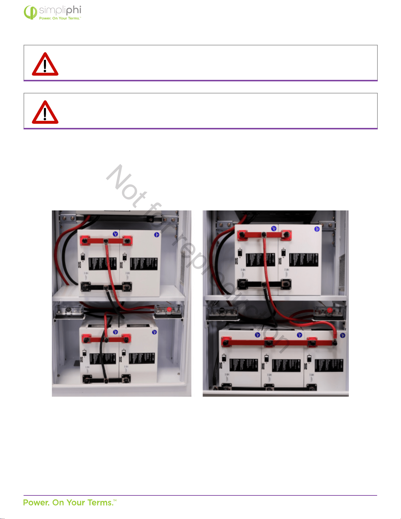
3. Place two PHI 3.8 baeries in the boom of the cabinet and arrange two or three PHI 3.8 baeries on the AccESS’s internal
shelf. Orient the modules so that the baery terminals point toward the AccESS door, with the negave posts nearest the
boom of the AccESS enclosure. Refer to Figure 11a and 11b below:
Figure 11a - Four PHI Baery Orientaon Figure 11b - Five PHI Baery Orientaon
Not for reproduction
© SIMPLIPHI POWER, INC.
SIMPLIPHIPOWER.COM | 805-640-6700 | BSREV202111141140
22
MODEL NO. 050000, 050001
4. Aach interconnecng busbars onto the baeries’ terminals. Each posive busbar parallels one set of two or three baeries
(posive to posive to posive), and each negave busbar parallels one set of two or three baeries (negave to negave to
negave). 2 baery interconnecng busbars ulize a 31”, 2 AWG cable. 3 baery inconnecng busbars ulize a 25”, 2/0
cable.
5. Secure the busbars to the baeries’ terminals using a 11/16” wrench socket to ghten the 3/8” lock washers and 11/16”
stainless steel hex nuts (originally included on the baeries). Tighten the nuts to 160 in-lbs.
6. Connect the included cables from the interconnecng busbars (secured to the baeries) to the 5-point terminal busbars
(see above). All connecons are in parallel: each posive cable connects from each interconnecng posive busbar to the
posive 5-point terminal busbar, and each negave cable connects from each negave busbar to the negave 5-point
terminal busbar (refer to Figure 11a and 11b on page 21).
7. Leave the PHI 3.8 baeries’ built-in breakers in the “OFF” posion unl the basic funconal test.
The PHI baeries’ charging regimen is not temperature compensated; do not include a Baery Temperature Sensor (BTS) wiring
connecon.
CAUTION: Adhere to all baery installaon instrucons as outlined in the PHI Baery Installaon Manual;
this manual does not substute the PHI Baery Installaon Manual.
CAUTION: PHI 3.8 Baeries must be fully charged before commissioning the AccESS unit (i.e. before
connecng loads for the rst me). Failure to do so will void the Warranty
CAUTION: SIMPLIPHI DOES NOT REQUIRE THAT THE PHI 3.8 BATTERIES WITHIN THE ACCESS BE
GROUNDED. IF A DC SYSTEM GROUND IS REQUIRED, ENSURE THAT THE SYSTEM BONDING IS DONE
IN ONE LOCATION ONLY, AND THAT ALL CONDUCTORS AND CONNECTIONS COMPLY WITH ALL
APPLICABLE NEC AND LOCAL INSTALLATION CODES.
Not for reproduction
© SIMPLIPHI POWER, INC.
SIMPLIPHIPOWER.COM | 805-640-6700 | BSREV202111141140
23
MODEL NO. 050000, 050001
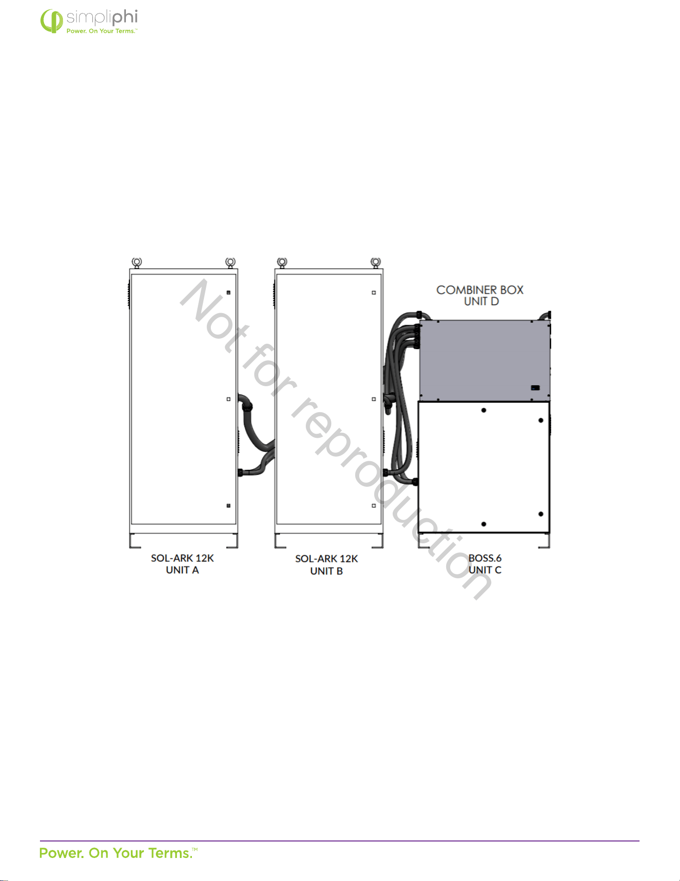
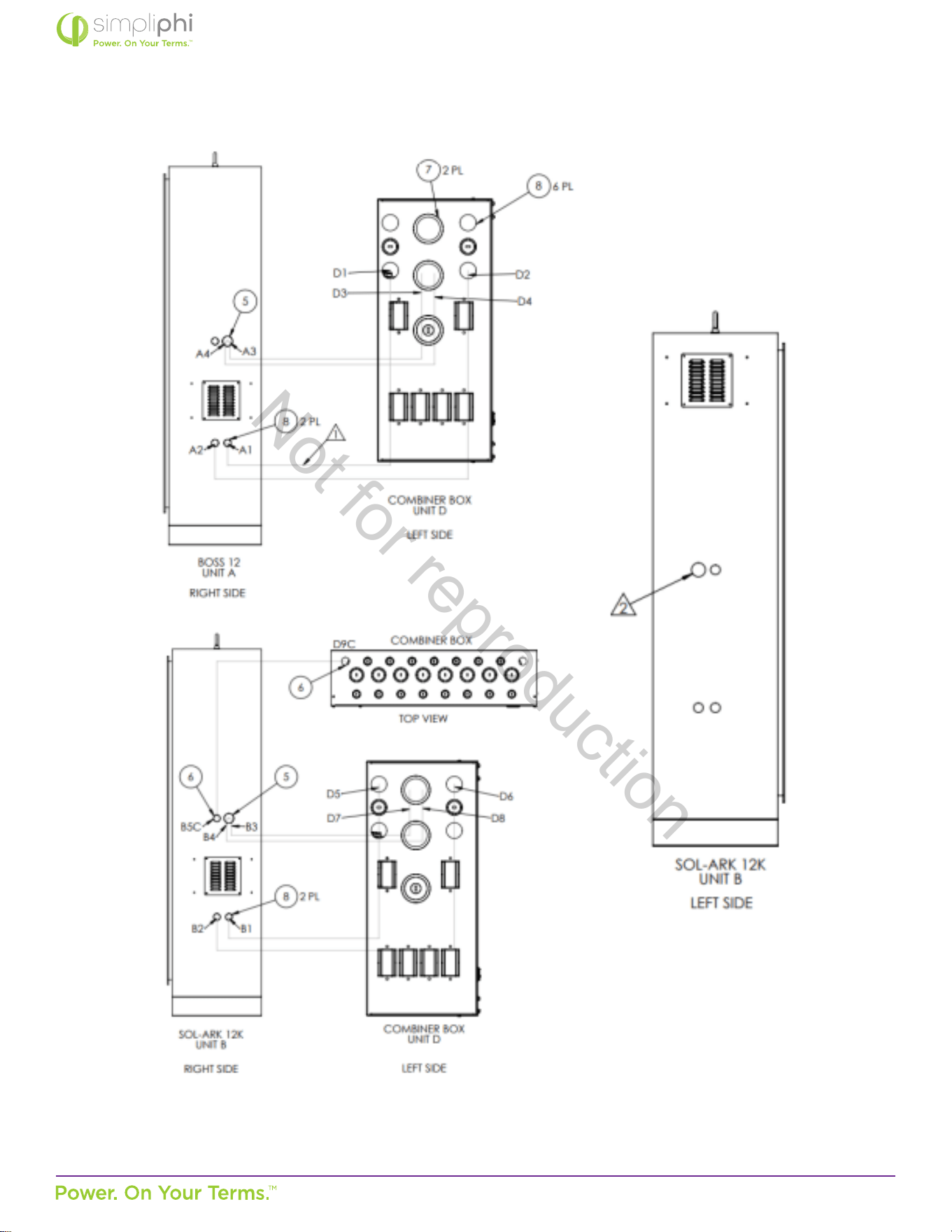
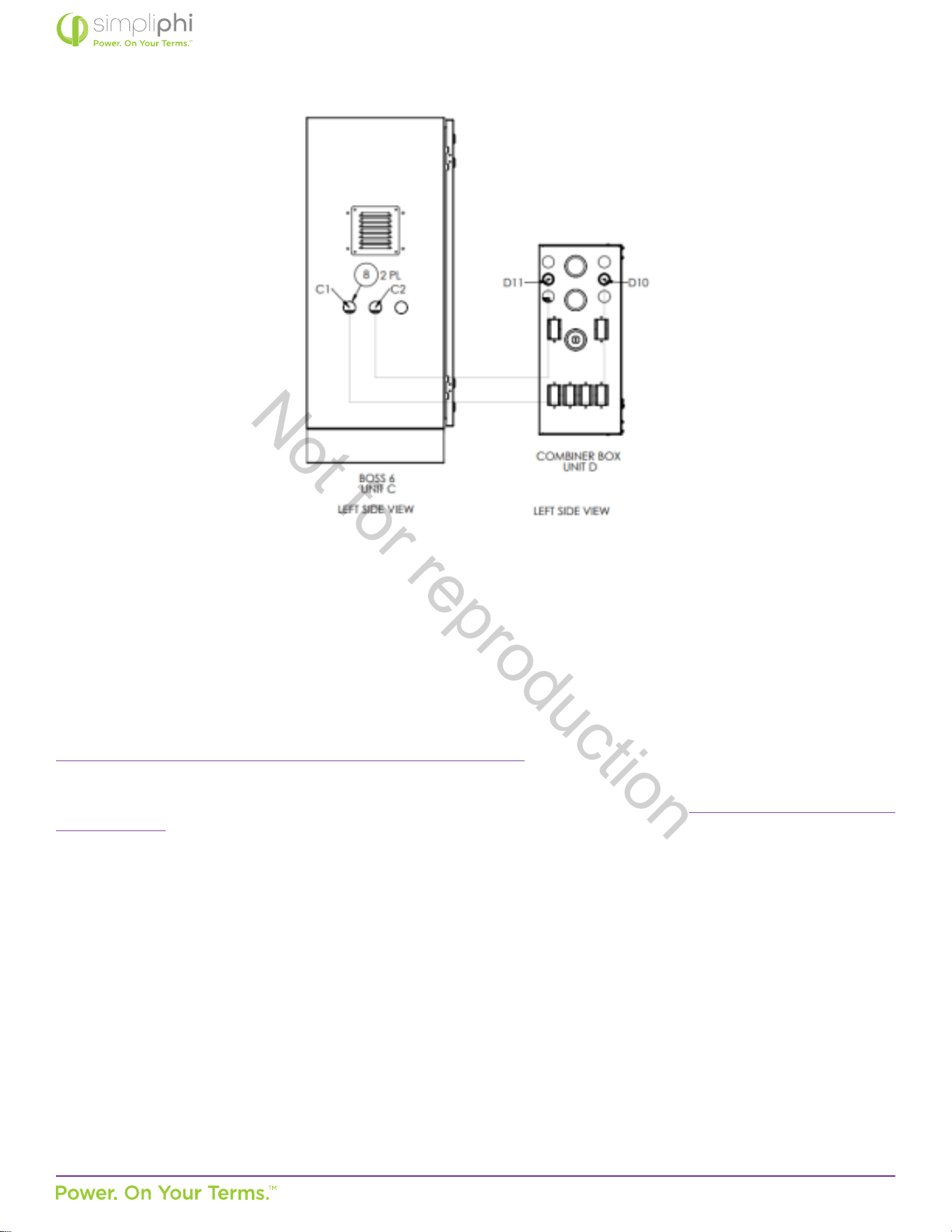
4.3 – Combining Connecons
Example: Two, A-5PHI-SA with added BOSS.6 with 4 or 5 PHI 3.8 baeries congured for residenal use that does not exceed
80 kWh. Each unit has 15.48 kWh or 19.35 kWh Maximum Rated Capacity x 3 units for a total Maximum Rated Capacity of
46.44 kWh or 58.05 kWh.
Not for reproduction
© SIMPLIPHI POWER, INC.
SIMPLIPHIPOWER.COM | 805-640-6700 | BSREV202111141140
24
MODEL NO. 050000, 050001
Not for reproduction
© SIMPLIPHI POWER, INC.
SIMPLIPHIPOWER.COM | 805-640-6700 | BSREV202111141140
25
MODEL NO. 050000, 050001
4.4 – Communicaons and Network Preparaon
The AccESS System includes system-level monitoring and programming via PowerView ES Monitor and Programming soware.
For online guidance regarding the Sol-Ark’s WiFi setup, watch these videos:
hps://www.youtube.com/watch?v=0H0OZfZz_kQ&feature=youtu.be
Step-by-step WiFi setup instrucons with screenshots and troubleshoong ps are included on pages 25 – 29 of the latest Sol-
Ark-12K Manual. These excerpts also appear in Appendix A of this Manual.
Not for reproduction
© SIMPLIPHI POWER, INC.
SIMPLIPHIPOWER.COM | 805-640-6700 | BSREV202111141140
26
MODEL NO. 050000, 050001
4.5 – Wiring the AccESS
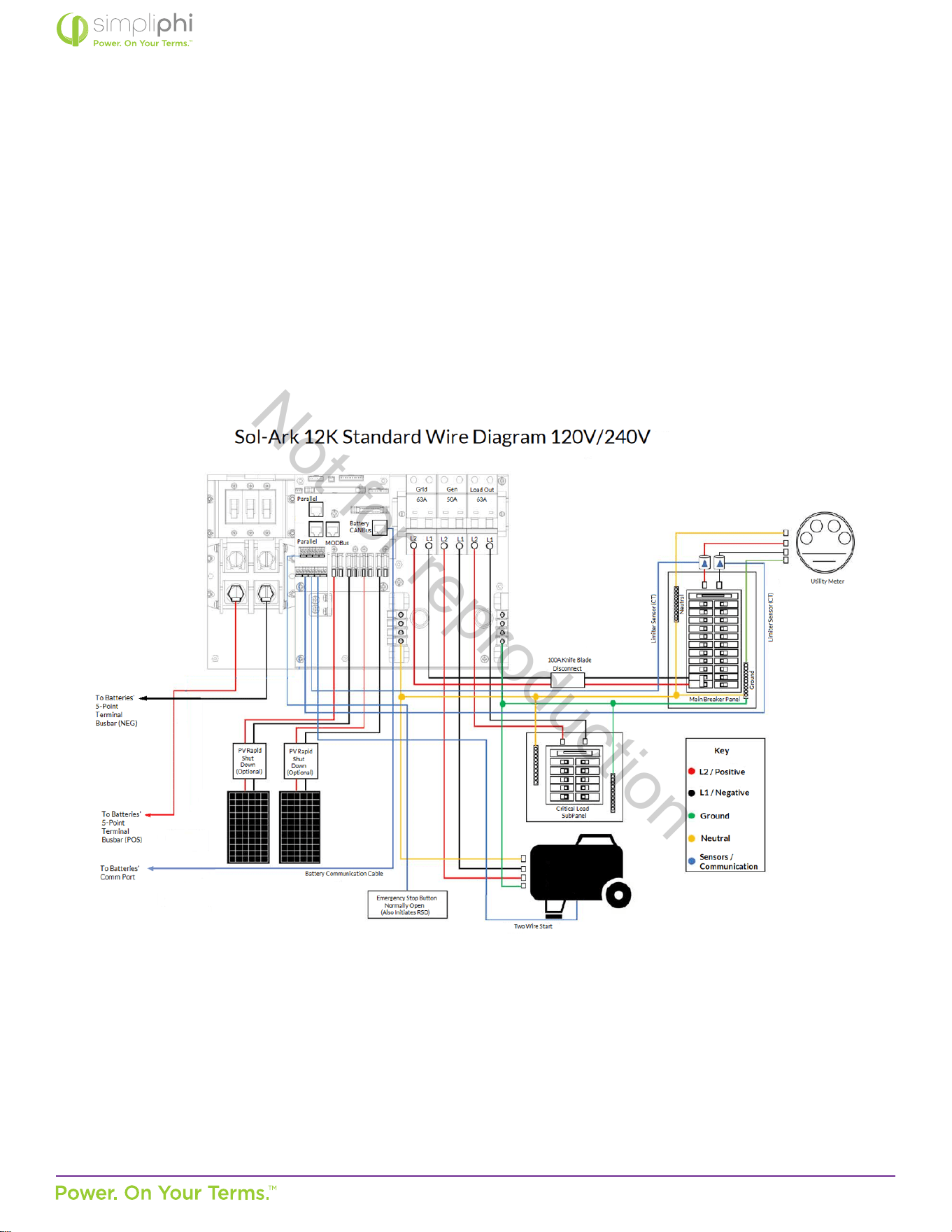
4.5.1 – Wiring Diagrams
Please reference the below listed DC coupling and AC coupling diagrams, where applicable.
Figure 12 - DC Coupled AccESS Sol-Ark Wiring Diagram
Not for reproduction
© SIMPLIPHI POWER, INC.
SIMPLIPHIPOWER.COM | 805-640-6700 | BSREV202111141140
27
MODEL NO. 050000, 050001
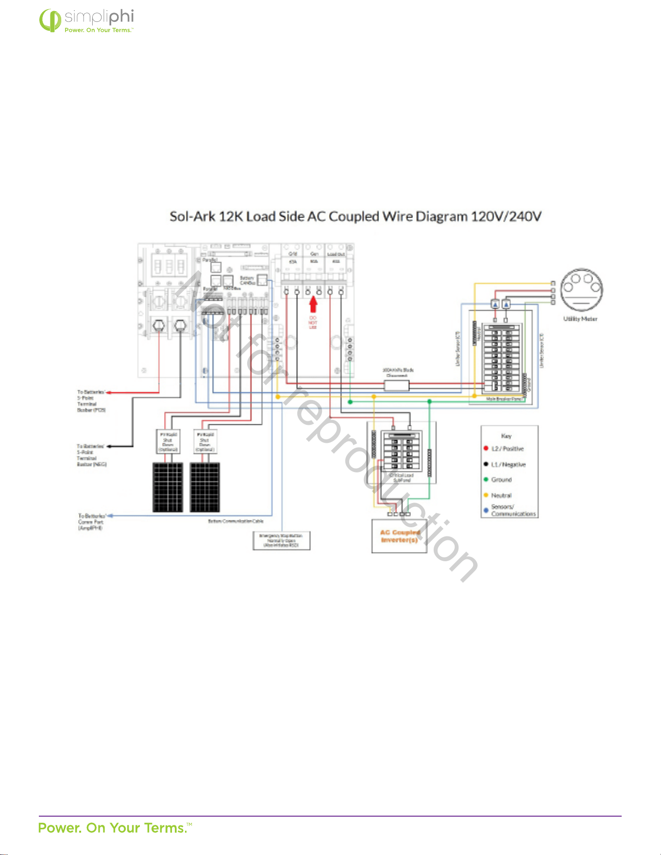
Figure 13 - Load Side AC Coupled AccESS Sol-Ark Wiring Diagram
• Important Note: If AC-coupling is on the load side, you will not see the power producon,
whereas the GEN breaker has a sensor that allows us to measure AC-Coupled panel producon
accurately.
• Addionally, the GEN port has a relay since it typically connects to a generator that would allow
for a physical disconnect to the GEN breaker. Therefore, if you were AC coupled with a unit that
does not comply with UL1741SA, connecng it to the GEN port would be required because the
Load port cannot do frequency curtailment.
Not for reproduction
© SIMPLIPHI POWER, INC.
SIMPLIPHIPOWER.COM | 805-640-6700 | BSREV202111141140
28
MODEL NO. 050000, 050001
4.5.2 – Making AC Connecons
AC Landing Points – Terminal Blocks
The AccESS is equipped with mulple knockouts on either side of the unit for accessibility to the Sol-Ark’s AC connecons.
All AC connecons are rated at 120/240 VAC. The bi-direconal grid port can also support two out of three phases of a 208
VAC grid connecon (the two phases being L1 and L2, 120° out of phase).
The Sol-Ark equipment includes the following:
• Bi-direconal Grid Port (AC In/Out): 63A double-pole breaker
• Bi-direconal Generator Port: 50A double-pole breaker
• Load Output (AC Out): 63A double-pole breaker
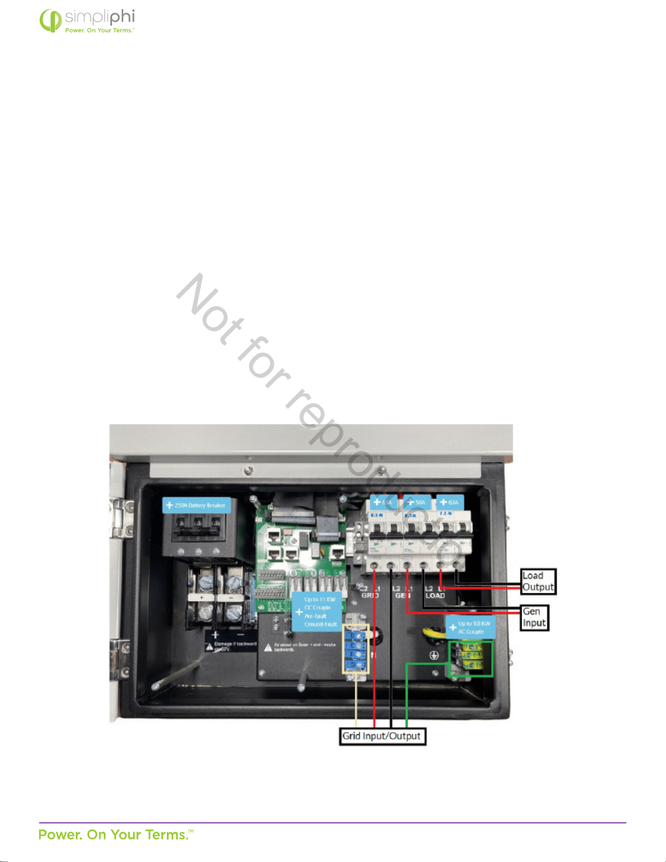
Figure 14.0 below shows the “Grid,” “Generator,” and “Load” connecon locaons. Also highlighted are the neutral and
ground AC terminal blocks.
Figure 14.0 - AC Power Input/Output Wiring Connecon Points
Not for reproduction
© SIMPLIPHI POWER, INC.
SIMPLIPHIPOWER.COM | 805-640-6700 | BSREV202111141140
29
MODEL NO. 050000, 050001
Grid AC Wiring
1. Install a double pole 60A breaker in the main house breaker panel. Best pracce dictates that this 60A 2P breaker be
installed at the opposite end of the busbar from the main breaker (typically at the boom of the main house breaker
panel).
2. Include an External AC Disconnect (with handle) between the 60A 2P breaker in the main house breaker panel and
the Sol-Ark’s “Grid” port.
• The External AC Disconnect must be sized larger than 60A and include a knife blade switch.
Generator AC Wiring
Generators wired to the Sol-Ark Split-Phase systems must be rated at 240VAC. Generators wired to the SolArk Three-
Phase systems must be rated at 208VAC. Installaons outside North America that incorporate generators rated at 230VAC
/ 50Hz can be wired to the Sol-Ark, provided there is no Neutral wiring connecon.
Generators can either be wired to the Sol-Ark’s Generator Input Port or to the Sol-Ark’s Bi-direconal Grid Port.
In grid-connected systems, generators cannot be wired to the Grid Port. However, the Sol-Ark’s Generator Input Port may
need to be ulized for purposes other than the generator’s connecon. AC Coupled systems or systems ulizing the Sol-
Ark’s Smart Load funconality are wired to the Sol-Ark’s Generator Input Port. In such scenarios, a whole-home generator
transfer switch is necessary to incorporate a generator into the system:
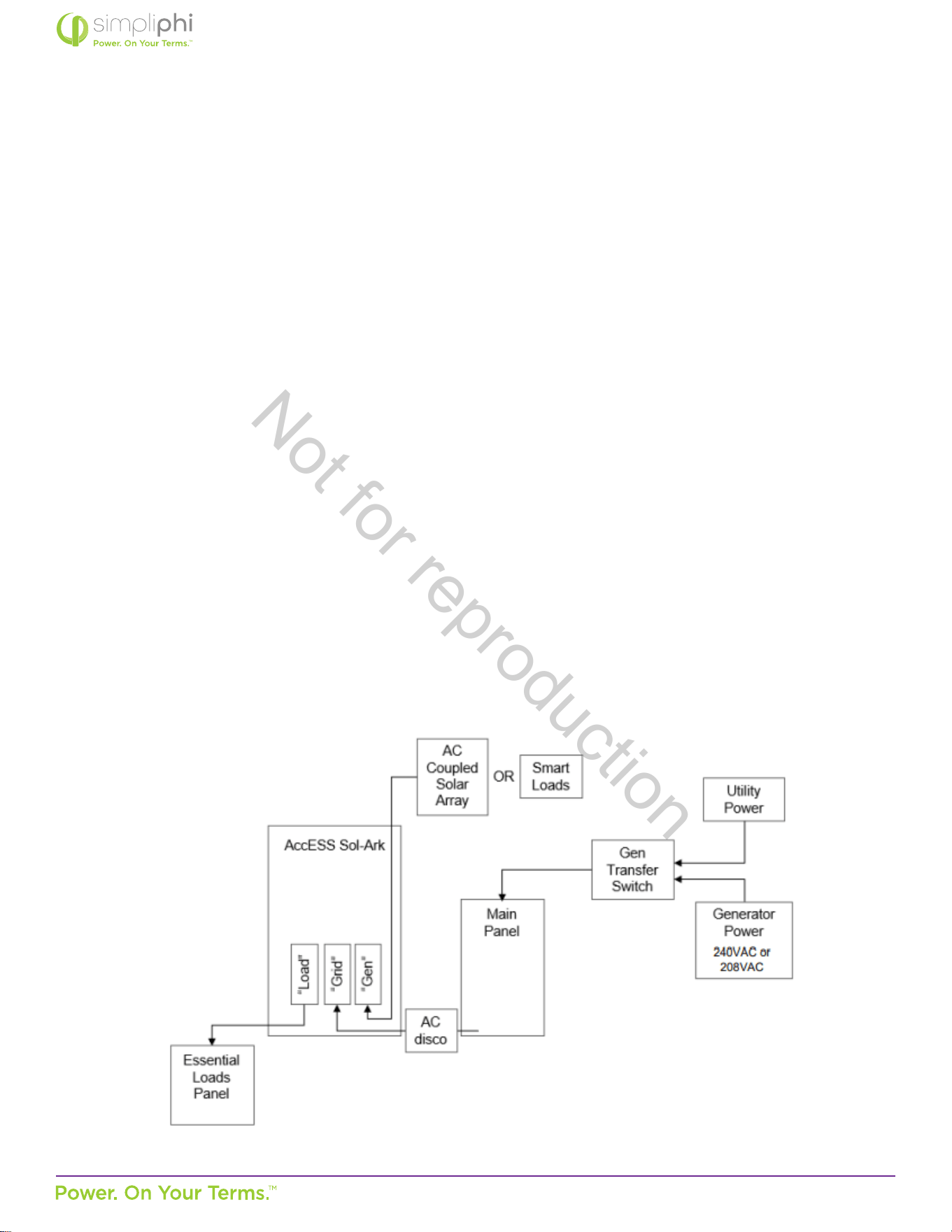
Figure 15 - Generator Wiring in Grid-Connected AC Coupled Systems
It is also acceptable, but not required, to use a whole-home generator transfer switch when the Generator Input Port
does not need to be ulized for an AC Coupled solar PV array or Smart Loads. This setup is typical for larger (10-30 kW)
generators. In o-grid systems, Sol-Ark recommends that the Grid Port be used for generator connecons.
Not for reproduction
© SIMPLIPHI POWER, INC.
SIMPLIPHIPOWER.COM | 805-640-6700 | BSREV202111141140
30
MODEL NO. 050000, 050001
Inverter Charger Grounding
The Sol-Ark includes a ground busbar (outlined in Figure 14.0). A wiring connecon must be made between the Sol-
Ark’s ground busbar and earth ground using appropriately sized equipment grounding conductors. The Sol-Ark’s ground
busbar accepts wire sizes up to 4 AWG. System grounding must be done according to all applicable NEC and local
installaon codes.
CAUTION: Adhere to the programming instrucons in the “Generators” sub-secon of Secon 5.3
(Conguring the Sol-Ark) in this Manual when incorporang a generator into the system
4.5.3 – AC System Bonding
Mulple AC Neutral-to-Ground Bonds
Verify that only one neutral-to-ground bond exists in the system. Having more than one neutral-to-ground bond in a
system violates local electrical codes, may create a shock or re hazard, and may cause some sensive equipment to
malfuncon. The Sol-Ark’s neutral busbar accepts wire sizes up to 4 AWG.
Failure to follow these instrucons can result in death or serious injury and will void the Warranty.
System bonding refers to connecon (bonding) of one of the current-carrying conductors of an electrical system to ground.
This creates a “grounded conductor” or “neutral” that is at ground potenal but is separate from the equipment ground
conductor. System bonding must be done at only one locaon. Procedures for system bonding vary between on-grid and
o-grid systems.
System bonding for on-grid systems
The Sol-Ark does not include a connecon between neutral and ground. The AC input neutral is already bonded to ground
by the incoming ulity grid system. Do not connect the neutral to ground in any addional locaon.
The Sol-Ark does not switch or disconnect the AC neutral in any mode of operaon, so even in invert (back-up) mode, the
inverter load sub-panel neutral is bonded to ground by the ulity grid system. It must not be grounded again in the inverter’s
load sub-panel.
System bonding for o-grid systems
In a system without a generator, or with a generator that does not provide a grounded neutral, you must make the
connecon from neutral to ground in the Essenal Loads panel (the inverter’s load sub-panel), which is actually the home’s
main house breaker panel in an o-grid system.
In a system with a generator that provides a grounded neutral, no addional connecon from neutral to ground is needed. In
this case, do not connect neutral to ground in the Essenal Loads panel (the inverter’s load subpanel).
Not for reproduction
© SIMPLIPHI POWER, INC.
SIMPLIPHIPOWER.COM | 805-640-6700 | BSREV202111141140
31
MODEL NO. 050000, 050001
1. Before connecng the solar PV, verify the cable polarity and mark the cable accordingly as Posive or Negave.
2. The AccESS Sol-Ark is equipped with mulple knockouts (see Figure 16.0 on the following page). Ulize any one of these
to feed the PV wiring from the PV disconnect into the AccESS enclosure.
Figure 16 - AccESS Cabinet Knockouts (sides)
4.5.4 – Making DC Connecons
The Sol-Ark contains two built-in MPPT charge controllers, each containing two solar PV input ports (for a total of four
PV string input ports per Sol-Ark). Adhere to the relevant Sol-Ark model’s charge controller specicaons when sizing the
paired solar PV array (explained further in this secon of the Manual).
1. Before connecng the solar PV, verify the cable polarity and mark the cable accordingly as Posive or Negave.
2. The AccESS Sol-Ark is equipped with mulple knockouts (see Figure 16.0 below). Ulize any one of these to feed the PV
wiring from the PV disconnect into the AccESS enclosure.
CAUTION: All solar PV strings wired to the same charge controller must be rated at the same voltage.
Not for reproduction
© SIMPLIPHI POWER, INC.
SIMPLIPHIPOWER.COM | 805-640-6700 | BSREV202111141140
32
MODEL NO. 050000, 050001
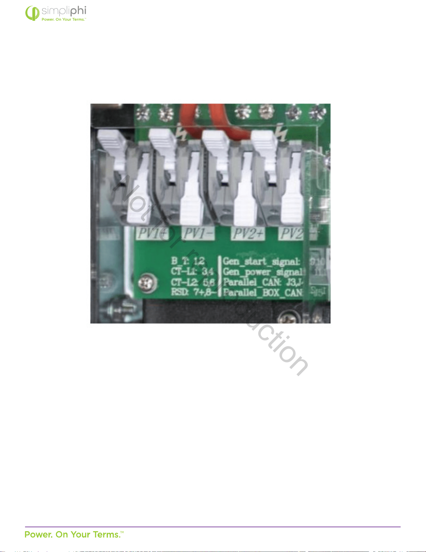
3. Strip 0.5” of insulaon from the PV conductors, and insert into the appropriate charge controller port.
Figure 17 - PV Array Connecon Points (DC Coupled Systems)
4. Ground the solar PV array by panel frame grounding to any ground connecon in the home using 12 AWG wire. Solar
PV mounng structures typically bond frames together, so only one ground wire is needed.
Not for reproduction
© SIMPLIPHI POWER, INC.
SIMPLIPHIPOWER.COM | 805-640-6700 | BSREV202111141140
33
MODEL NO. 050000, 050001
AccESS Sol-Ark System Solar PV Array Sizing
The Sol-Ark-12K’s built-in MPPT charge controller specicaons are:
• Quanty of built-in MPPT charge controllers per Sol-Ark-12K = 2
• Quanty of PV ports per MPPT charge controller = 2
• Total quanty of PV ports per Sol-Ark-12K = 4
• MPPT charge controller starng voltage = 125VDC
• Maximum DC Voltage input per MPPT charge controller = 500VDC
• MPPT charge controller voltage range = 150-425VDC
• Maximum ISC current input per MPPT charge controller = 25A
• Maximum operang current input per MPPT charge controller = 20A
• Maximum baery charging current per Sol-Ark-12K = 185A
CAUTION: It is crical that the solar PV string’s voltage does not exceed 500VOC; voltage greater than
550VDC will damage the Sol-Ark equipment.
To properly congure solar PV modules to the Sol-Ark’s built-in charge controllers:
1. Due to the charge controller’s starng voltage of 125VDC, calculate the minimum number of solar panel modules
needed to meet this target voltage at the module’s maximum power voltage (VMP).
In this example, consider the Canadian Solar KuPower CS3K-300 solar PV module with a VMP of 32.5V at Standard Test
Condions (STC).
• Four modules in series are required to meet the charge controller’s minimum MPPT tracking voltage requirement:
125V ÷ 32.5V = 3.9 (round up to the next whole number).
Not for reproduction
© SIMPLIPHI POWER, INC.
SIMPLIPHIPOWER.COM | 805-640-6700 | BSREV202111141140
34
MODEL NO. 050000, 050001
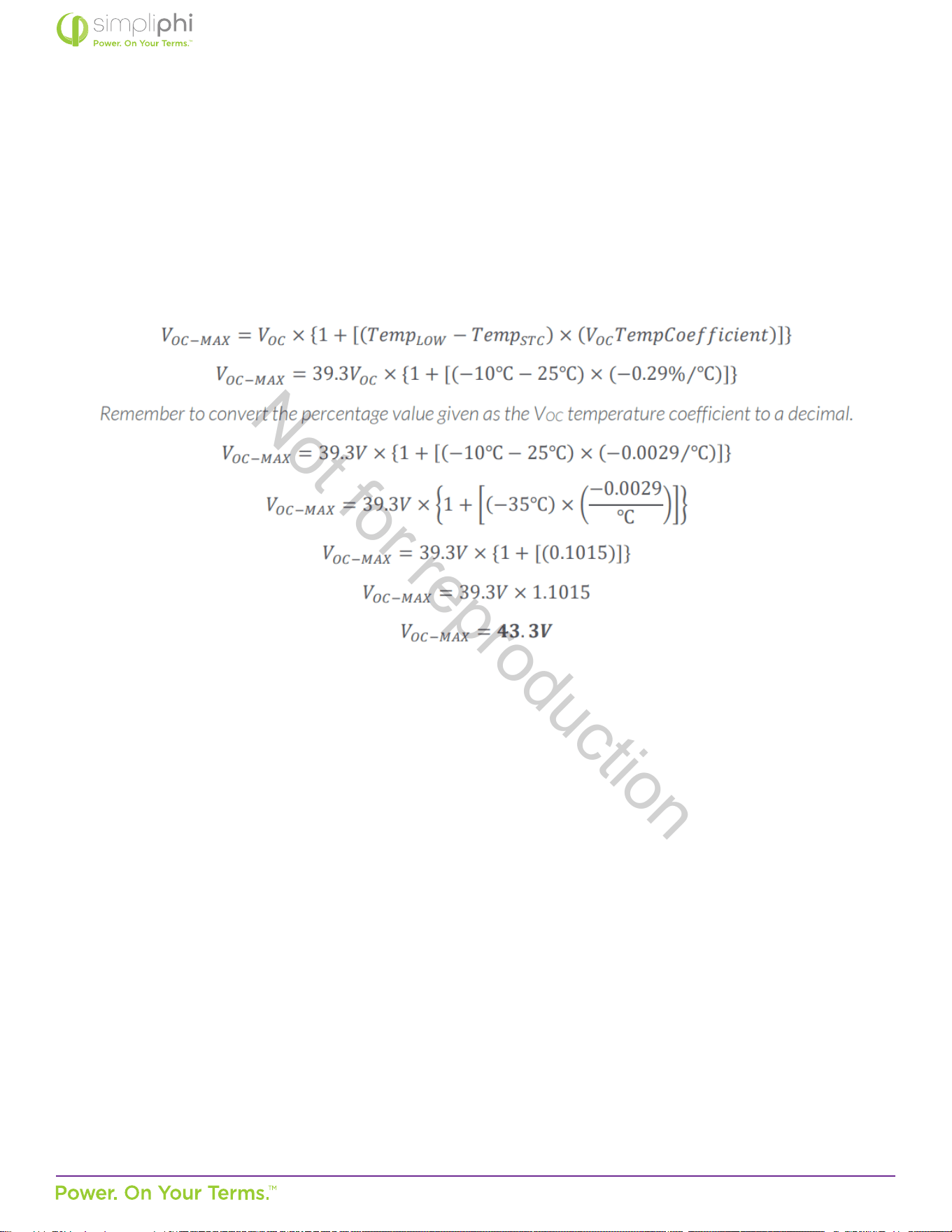
2. The charge controller’s maximum DC voltage input is 500VDC. Temperature aects the solar PV module’s voltage
output: voltage increases as temperature decreases. To calculate the maximum number of solar panel modules in series
per PV string, consider the module’s open circuit voltage (VOC) rang, temperature coecient and lowest expected
temperature at the installaon site.
In this example, the KuPower 300W module has a VOC of 39.3V at STC, a STC temperature of 25°C, and a VOC
temperature coecient of -0.29%/°C.
To calculate the solar module’s VOC in an extreme low temperature condion of, say, -10°C:
• Eleven modules is the maximum allowable number of modules in series to prevent the solar PV string from exceeding the
charge controller’s maximum voltage input rang even in the coldest weather condions at the installaon site: 500V ÷
43.3V = 11.5 (round down to the next whole number).
• Eleven modules in series at the KuPower 300W module’s VMP rang of 32.5V at STC also equates to 357.5V, well
within the charge controller’s 150-425VDC maximum power point tracking range.
Not for reproduction

© SIMPLIPHI POWER, INC.
SIMPLIPHIPOWER.COM | 805-640-6700 | BSREV202111141140
35
MODEL NO. 050000, 050001
3. The charge controller’s maximum short circuit current (ISC) input is 25ADC. Temperature also slightly aects the solar
PV module’s current output: current increases as temperature increases. However, because the temperature coecient
is negligible, it is acceptable to simply use the module’s ISC rang at STC for the following calculaon.
To calculate the maximum number of solar PV strings per charge controller in this example, consider the KuPower 300W
module’s ISC at STC: 9.82A.
• According to this calculaon, two solar PV strings is the maximum allowable number of strings per charge controller:
25A ÷ 9.82A = 2.5 (round down to the next whole number).
• Although the Sol-Ark contains only two solar PV string inputs, more than two strings in parallel can be wired to the Sol-
Ark. If more than two strings are connected in parallel to a single charge controller, each string must be fused (refer to
page 10 of the Sol-Ark-12K Manual).
• Three solar PV strings in parallel at the KuPower 300W module’s IMP rang of 9.24A equates to 27.72A at STC, above
the charge controller’s operang current input limit of 25A. Whereas two solar PV strings in parallel at the KuPower
300W module’s IMP rang of 9.24A equates to 18.48A at STC, well within the limits of the charge controller’s operang
current input limit of 20A. Therefore, in this example, no more than two strings in parallel per charge controller should
be used.
Based on calculaons #2 and #3 above, a maximum two parallel strings of eleven KuPower 300W modules in series can be
wired to each of the Sol-Ark-12K’s two charge controllers.
4. The charge controller can be paired with a maximum 6,500 Was of solar PV Waage.
In this example, the KuPower 300W module has a Maximum Power (PMAX) rang of 300W at STC.
• 21 modules are the maximum allowable number of modules that can be paired per charge controller:
6,500W ÷ 300W = 21.6 (round down to the next whole number).
5. The Sol-Ark-12K (with two built-in charge controllers) can be paired with a maximum 13,000 Was of solar PV
Waage.
In this example, the KuPower 300W module has a Maximum Power (PMAX) rang of 300W at STC.
• 43 modules are the maximum allowable number of modules that can be paired per Sol-Ark12K:
13,000W ÷ 300W = 43.3 (round down to the next whole number).
Considering all ve of the above calculaons, and maintaining equal elecrical characteriscs among parallel strings, the
opmal solar module conguraon in this example is wiring a maximum two parallel strings of ten KuPower 300W modules
in series to each of the Sol-Ark-12K’s two charge controllers, for a total of 40 modules paired with the Sol-Ark-12K.
Not for reproduction
© SIMPLIPHI POWER, INC.
SIMPLIPHIPOWER.COM | 805-640-6700 | BSREV202111141140
36
MODEL NO. 050000, 050001
4.5.5 – Limiter Sensor Wiring Connecons
The Sol-Ark AccESS installaon may include limiter sensors. Limiter sensors are required in the following applicaons:
• Limited to Home mode
• Time of Use Selling mode
• Systems that include both a generator and grid connecon
Install limiter sensors on incoming electrical service wires L1 and L2, at the top of the main house breaker panel (refer to Sol-
Ark’s diagram within their manual).
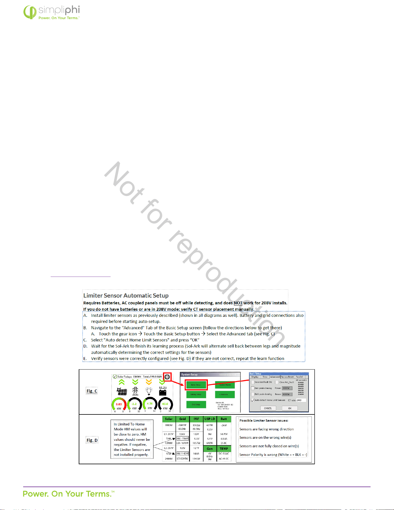
Verify the limiter sensors’ proper sense and direcon by adhering to the Sol-Ark manual’s “Tesng and Powering Up Sol-Ark”
instrucons in the Sol-Ark Manual. If applicable, perform the following checks aer compleng Steps 1 and 2 outlined in the
Basic Funconal Test Secon 4.5.6 below:
If MCU SW = 1654 or higher, an auto learn funcon avoids all this.
• Using AC mul-meter, verify L1 voltage on AC in/out is 0Vac with main L1 connecon in panel. Same for L2.
• To verify sensor connecons to Sol-Ark, try removing one sensor from the main L1 connecon. The power should drop
to 0W.
• To verify proper sensor direcon, with any loads in the home, the HM: +was will be posive. If you turn on solar panels
and turn enable Grid Sell, you should see HM: -was if you are producing more power than the loads are consuming.
And if you turn on limited power to Home mode, then HM: ~0 was to zero the meter (system matches the loads to
within 99%).
From Sol-Ark - 12K Manual
Not for reproduction
© SIMPLIPHI POWER, INC.
SIMPLIPHIPOWER.COM | 805-640-6700 | BSREV202111141140
37
MODEL NO. 050000, 050001
4.5.6 – Basic Funconal Test
The following procedure should be followed once the installaon is complete and before it is put into service.
Step 1: Conrm All Connecons
Aer the AC and DC wiring has been installed and connected, check that all connecons are correct and secure.
Step 2: Apply Baery Power to the Inverter
1. Measure the voltage and check polarity at all baery connecon points. Measure the enre PHI baery bank’s voltage
and polarity on the Sol-Ark’s DC Posive and DC Negave connecon points, outlined in Figure 18.0 below.
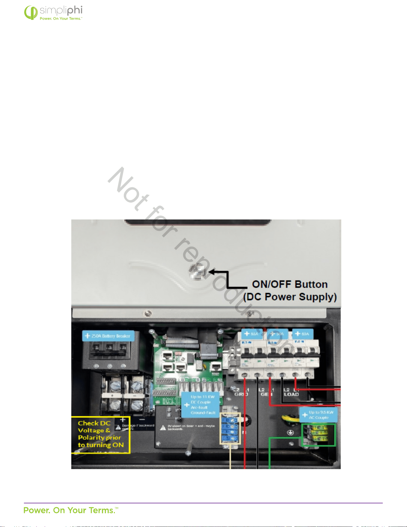
Note: The Sol-Ark includes a 250ADC Disconnect breaker.
Figure 18 - Inverter & DC Power Supply ON/OFF Buon
Not for reproduction

© SIMPLIPHI POWER, INC.
SIMPLIPHIPOWER.COM | 805-640-6700 | BSREV202111141140
38
MODEL NO. 050000, 050001
2. Supply DC power to the Sol-Ark inverter by turning ON the ON/OFF buon on the front of the SolArk unit.
3. The inverter will power up and the inverter display panel will turn on.
Step 3: Verify Inverter Programming
Although the AccESS Sol-Ark is pre-programmed to the correct baery charging parameters, the Sol-Ark equipment
oers dierent funconality based on various other sengs. Refer to this Manual’s Programming secon 5.0 for more
informaon. Update rmware to the latest version.
Step 4: Apply DC and AC Power to the Inverter
Turn all relevant DC and AC disconnects ON. When rst commissioning the system, leave the Sol-Ark’s Load Output breaker
OFF, and all circuits in the main house breaker panel OFF (if the Sol-Ark is programmed to a mode of operaon in which the
baeries discharge to the main house breaker panel; refer to Secon 5.3 of this Manual for more informaon on the Sol-
Ark’s modes)
Step 5: Fully Charge the Baery Bank Prior to Powering on Loads
A connecon to an AC power source will result in the Sol-Ark automacally charging the baeries from that power source
when the Sol-Ark is turned ON.
If the system does not include any AC power source, and only solar PV as the baeries’ charging source, turn on the PV
disconnect and wait unl the PHI baery bank has had a chance to charge fully via solar power before turning on any loads.
For DC Coupled systems, the solar PV array’s ON/OFF switch is on the le hand side of the Sol-Ark unit.
Step 6: Turn on Loads
Fully charged PHI baeries will reach a charging voltage of 54.4 – 56 VDC and will then “rest” at approximately 53.3 VDC
as soon as they are no longer acvely charging. At this point, turn on the Sol-Ark’s Load Output breaker and main house
breaker panel circuits, if applicable.
4.5.7 – Lockout / Tagout
Step 1: Detailed procedures for equipment
Begin by making sure you’ve idened the equipment correctly and accurately, including its specic locaon. Next,
determine the correct procedure for shung down and restarng the equipment. Detail that procedure, step by step, in
wring. Consider all of the energy sources that may be connected to the equipment. Be very specic, because ambiguous
language could lead to an incorrect or even dangerous acon.
Not for reproduction

© SIMPLIPHI POWER, INC.
SIMPLIPHIPOWER.COM | 805-640-6700 | BSREV202111141140
39
MODEL NO. 050000, 050001
Step 2: Nofy aected employees
When maintenance is going to be performed, all of the employees that may be aected should be noed. Let them know
the ming of the work, and how long the equipment may be unavailable. If the unavailability of the equipment requires a
change in work processes, be sure they are familiar with the steps to be taken.
Step 3: Shut down equipment properly
Explain the shutdown process in detail. It’s not enough to say something like “disconnect the machine.” To ensure everyone’s
safety and reduce the potenal for damage, the shutdown instrucons should be detailed. Spell out the exact acons to be
taken and the correct sequence for performing those acons.
Step 4: Disconnect all primary energy sources
Although this may seem fairly self-explanatory, once again, it’s important to be very detailed. Whether the primary
energy sources include electricity, steam, water, gas, compressed air, or others, don’t assume that the person performing
maintenance will know the correct procedure to follow. Again, explain exactly what needs to be done.
Step 5: Address all secondary sources
While disconnecng the primary energy sources may remove much of the potenal danger, it’s possible that there sources
of residual energy, such as trapped heat in a thermal system, fumes that may need to be vented, or even tension in a spring
assembly. Idenfy the process that will relieve any remaining pressure or other energy. Also consider other hazards, such as
moving equipment that must be secured before work begins.
Step 6: Verify the lockout
Once you’ve disconnected all primary and secondary sources of energy, aempt to start the equipment to verify that the
lockout has been successful. Before you try to start it, verify that nobody is in a posion where they could be hurt. Assuming
that the procedures have been successful, return all switches and other equipment back to their “o” posions so the
machine won’t start unexpectedly when the energy sources are reconnected. Once you’ve veried the lockout, aach a
lockout or tagout device to the equipment to ensure that it cannot be started without removing the device.
Step 7: Keep it in force during shi changes
The equipment must remain in lockout/tagout condion across shi changes, so that workers arriving at the site are
aware that the equipment is out of service. If individual locks or tags are used, the individual responsible for designang
the lockout/tagout and the individual responsible for it during the next shi must both be present as the locks or tags are
switched.
Not for reproduction

© SIMPLIPHI POWER, INC.
SIMPLIPHIPOWER.COM | 805-640-6700 | BSREV202111141140
40
MODEL NO. 050000, 050001
Step 8: Bring the equipment back online
When the work is done and all tools and other materials have been removed, the machine can be brought back into
operaon. Here again, the procedure should spell out the exact steps that are involved, along with the correct sequence. For
example, you may need to open a parcular machine’s discharge valves before you open the inlet, so any unexpected water
or steam remaining in the lines has a place to go.
Bonus step: Keep procedures up to date
Equipment and operang procedures tend to change over me, and your lockout/tagout program needs to reect those
changes. Somemes, the changes may be so minor that only the people working directly with the equipment are aware of
them. That’s why it’s a good idea to review all your lockout/tagout procedures regularly to verify that they’re sll accurate.
A company with just a small number of machines may be able to check all of them every year, while a larger organizaon
may need to study a certain number or a random sample every year. Another benet of regular review is that it gives you an
opportunity to deploy newer and beer ideas or more accurate descripons.
Not for reproduction
© SIMPLIPHI POWER, INC.
SIMPLIPHIPOWER.COM | 805-640-6700 | BSREV202111141140
41
MODEL NO. 050000, 050001
5.0 – Programming
5.1 – Depth of Discharge
The AccESS Sol-Ark comes pre-programmed for a maximum 80% depth of discharge (DoD) on the PHI baeries. To change the
baeries’ DoD, modify the State of Charge (SoC) percentages as outlined in this Operang Parameters secon of this Manual.
If a rmware update is executed on the AccESS, please verify all PHI custom sengs are sll in place.
5.2 – Operang Parameters Per Warranty
Inverter/Charge Controller Sengs
For online programming guidance, refer to Sol-Ark’s Menus and Programming video
(hps://www.youtube.com/watch?v=mcXXzgfRT90&t=1497s) when programming those sengs outlined in Table 2.0 on the
following page.
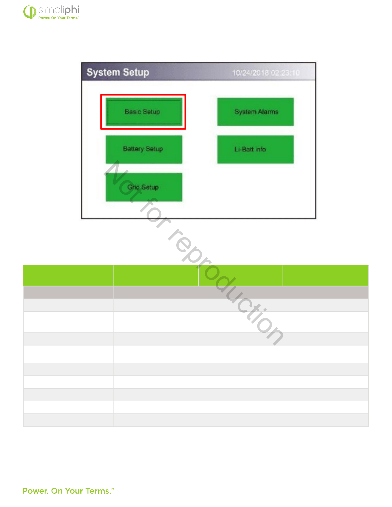
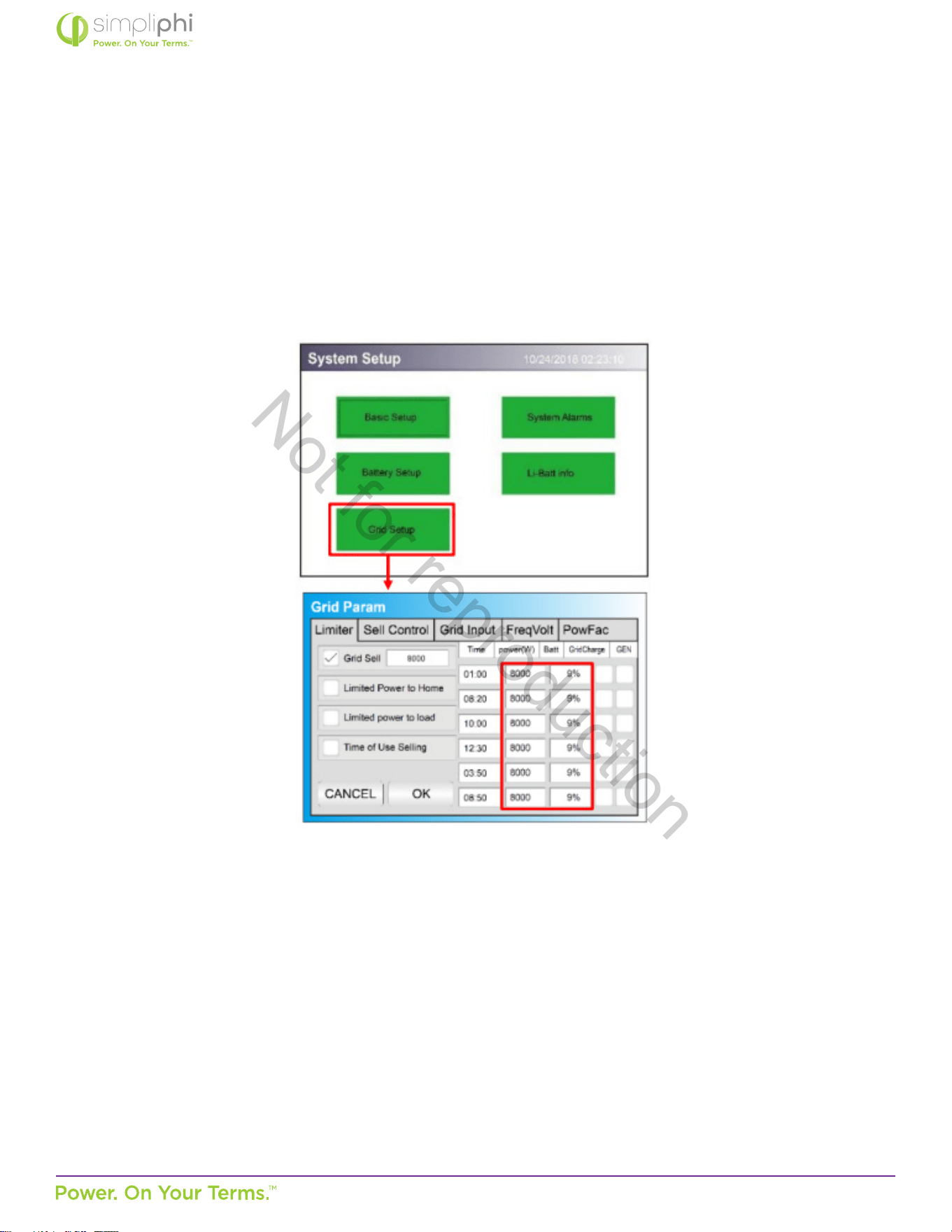
Press the gear icon to get to the Sengs menu (Figure 19.0), then press Baery Setup (Figure 20.0) to program the parameters
in Table 2.0.
Not for reproduction
© SIMPLIPHI POWER, INC.
SIMPLIPHIPOWER.COM | 805-640-6700 | BSREV202111141140
42
MODEL NO. 050000, 050001
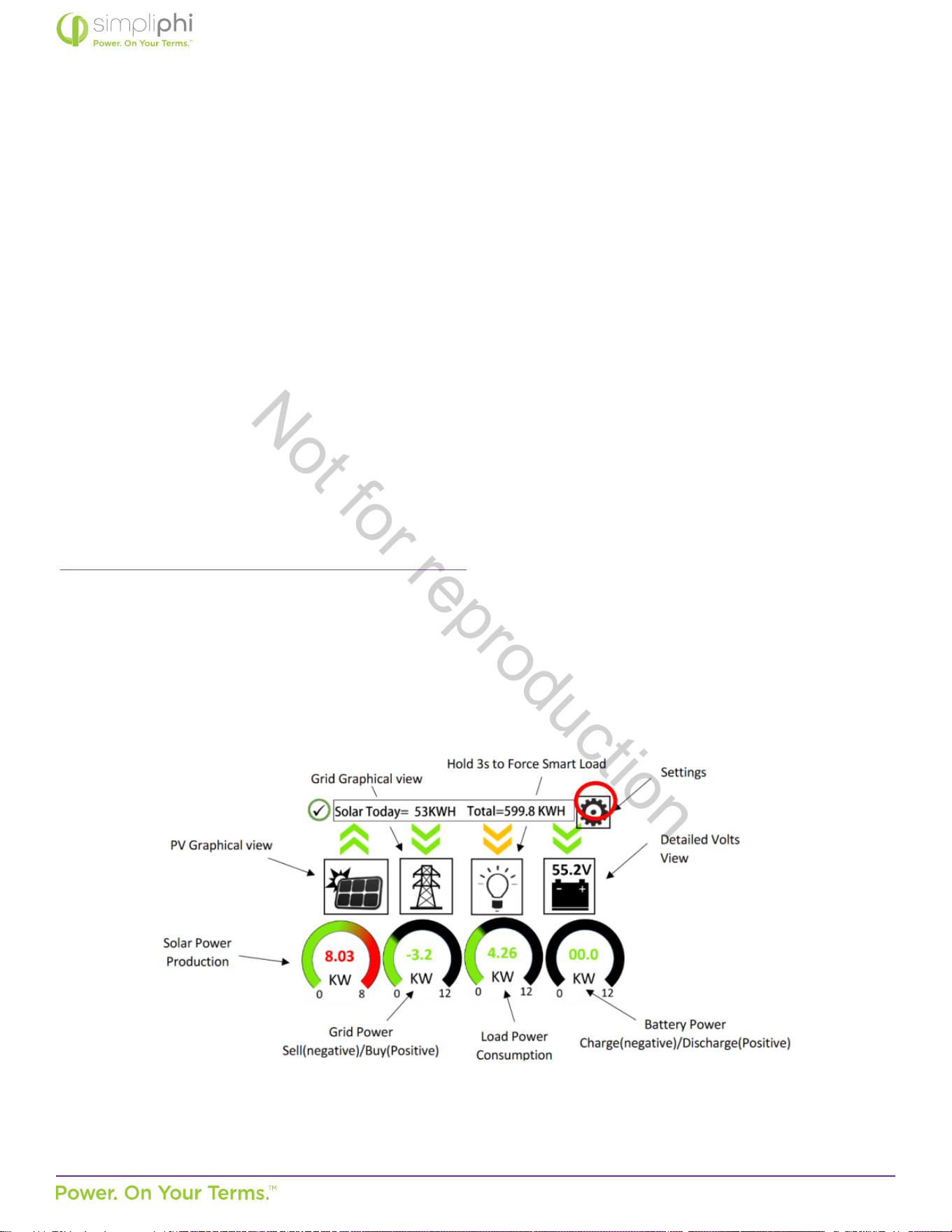
Figure 19 - Sol-Ark Home Screen (Touchscreen)
Figure 20 - Sol-Ark System Setup Screen
System Setup > Baery Setup
80% DoD
(10,000 cycles)
90% DoD
(5,000 cycles)
100% DoD
(3,500 cycles)
Dimensions
Ba Capacity
1
75 Ah per PHI 3.8 baery
Max A Charge
1,2
37.5 ADC per PHI 3.8 baery (20 ADC per baery for reduced stress)*
*The Sol-Ark’s maximum PV charging output is limited to 185 ADC.
Max A Discharge
1
37.5 ADC per PHI 3.8 baery
TEMPCO 0 mv/C/Cell (disabled)
Use Ba V Charged do not check this box
Use Ba % Charged check this box
No Baery do not check this box
BMS Lithium Ba do not check this box
Acvate Baery do not check this box
Not for reproduction

© SIMPLIPHI POWER, INC.
SIMPLIPHIPOWER.COM | 805-640-6700 | BSREV202111141140
43
MODEL NO. 050000, 050001
System Setup > Baery Setup
80% DoD
(10,000 cycles)
90% DoD
(5,000 cycles)
100% DoD
(3,500 cycles)
> Charge Tab 80% DoD 90% DoD 90% DoD
Start V
Use Start % instead of Start V when using
Ba % Charged instead of Ba V Charged (in the Ba tab)
Start %
3
21% 11% 1%
A
1,4
37.5 ADC per PHI 3.8 baery (20 ADC per baery for reduced stress)*
*The Sol-Ark’s maximum AC power charging output is limited to 185 ADC.
Gen Charge / Grid Charge
5
Check the Gen Charge box when a generator is connected to the Gen Input breaker.
Check the Grid Charge box when a generator is connected to the Grid Input breaker,
or when a grid connecon is ulized to charge the baeries.
Float V 54 V
Absorpon V
6
56 V
Equalizaon V
7
56 V
30 days
2 hours
> Discharge Tab 80% DoD (Recommended) 90% DoD 90% DoD
Shutdown 20% (50.2 V) 10% (49.5 V) 0% (48 V)
Low Ba 30% (50.5 V) 20% (50.2 V) 10% (49.5 V)
Restart 40% (51 V) 40% (51 V) 40% (51 V)
Ba Resistance Resistance mOhms = 96 ÷ (4 × PHI 3.8 baery quanty)
Ba Charge Eciency 99%
> Smart Load Tab
Use Gen input as load output check this box if the Smart Load feature applies (refer to Secon 5 of this Guide)
Smart Load OFF Ba
8
95% (51.7 V)
Smart Load ON Ba
9
100% (52.5 V)
Waage value is used in grid-connected systems only. This value representa the minimum power
required of the solar array before the Smart Loads are powered
For Micro inverter input check this box for AC coupled systems
Smart Load OFF Ba
10
100% (52.5 V)
Smart Load ON Ba
11
30 - 95%
Not for reproduction
© SIMPLIPHI POWER, INC.
SIMPLIPHIPOWER.COM | 805-640-6700 | BSREV202111141140
44
MODEL NO. 050000, 050001
Notes:
1. These sengs are calculated by mulplying the per-baery value by the number of baeries in the connected baery
bank.
2. Max A Charge refers to the maximum charge rate from the solar PV array. Programming this value to the maximum
value versus the reduced-stress value does not impact the PHI Baery Warranty.
3. If the Auto Generator Start is ulized, the AGS is triggered when the baeries reach this set State of Charge (SoC)
percentage. Once triggered, the generator charges the baeries unl they reach approximately 95% SoC, at which
point the generator turns o. This 95% SoC parameter is not programmable.
4. A refers to the maximum charge rate from the grid or the generator. If the Sol-Ark is connected to both the grid and a
standby generator, the Sol-Ark priorizes the grid as the baeries’ charging source. Programming the A value to the
maximum value versus the reduced-stress value does not impact the PHI Baery Warranty.
5. By default, baery charging from the solar PV array is priorized over generator or grid charging.
6. When the baery has reached the Absorpon voltage setpoint, the Sol-Ark ulizes constant-voltage regulaon to
maintain the baery at the programmed Absorpon voltage. The Absorpon phase lasts unl the baeries charge at 2%
of the programmed Ah size. For example, one PHI 3.8-51.2Vnom baery (rated at 75 Ah), will remain in the Absorpon
charging phase unl the number of Amps used to charge the baery decreases to 1.5 Amps DC (2% of 75Ah).
7. While the PHI Baery does not require an Equalizaon charge, programming Equalizaon to the voltage, frequency and
duraon outlined in the table above ensures that the Sol-Ark’s internal SoC meter re-sets to 100% SoC every 30 days.
8. Smart Loads are no longer powered via solar and/or baeries when the baeries’ SoC level drops below this
programmed Smart Load OFF Ba value.
9. Smart Loads are powered via solar and/or baeries when the baeries’ SoC level exceeds this programmed Smart Load
ON Ba value.
10. The Sol-Ark stops charging the baeries and powering the loads from the AC Coupled solar PV array once the baeries’
SoC level reaches the Smart Load OFF Ba value.
11. The Sol-Ark triggers the AC Coupled solar PV array to produce power (powering the loads and charging the baeries)
when the baeries’ SoC level exceeds this programmed Smart Load ON Ba value.
CAUTION: When PHI baery quanes change, the capacity & charge/discharge current sengs
must be reassessed. Failure to do so will Void the Warranty. Modicaon to original factory sengs
can only be accessed by using installer password.
Not for reproduction
© SIMPLIPHI POWER, INC.
SIMPLIPHIPOWER.COM | 805-640-6700 | BSREV202111141140
45
MODEL NO. 050000, 050001
Grid Setup Sengs
The Sol-Ark’s Grid Setup menu includes many advanced features (refer to Secon 5 of this Guide). Regardless of the features
used, the PHI baery bank should never discharge more than its maximum connuous discharge rate. Furthermore, to maintain
the PHI baeries’ 10,000-cycle level, do not discharge the baery bank to a State of Charge (SoC) level less than 20%. These
details are controlled in the Grid Setup menu’s Limiter tab.
Figure 21 - Limiter Tab in Grid Setup Menu
The power (W) column in Figure 21.0 above dictates the maximum amount of power pulled from the baeries and should be
set to the PHI baery bank’s maximum discharge rate in AC Was. To calculate the connected PHI baery bank’s maximum
discharge Was (AC):
1. Mulply the number of baeries in the bank by the maximum discharge rate (ADC) per baery
• PHI 3.8-51.2Vnom baery max. discharge rate = 37.5 ADC per baery
2. Convert the baery bank’s DC discharge current to DC discharge was.
3. Apply the discharge eciency.
Populate the Ba column to the right of the power (W) column according to the degree to which you wish to discharge the
baery bank. Again, to maintain the PHI baeries at the 10,000-cycle level, do not populate the Ba column with any value less
than 20%.
Not for reproduction
© SIMPLIPHI POWER, INC.
SIMPLIPHIPOWER.COM | 805-640-6700 | BSREV202111141140
46
MODEL NO. 050000, 050001
5.3 – Conguring the Sol-Ark to a Specic Applicaon
The Sol-Ark is capable of many dierent modes of operaon via congurable sengs (more than one mode can be used
simultaneously). This secon of the Manual will outline the system programming and setup basics for common use cases.
However, refer also to the Sol-Ark Manual for all installaon requirements relevant to the applicaon at hand.
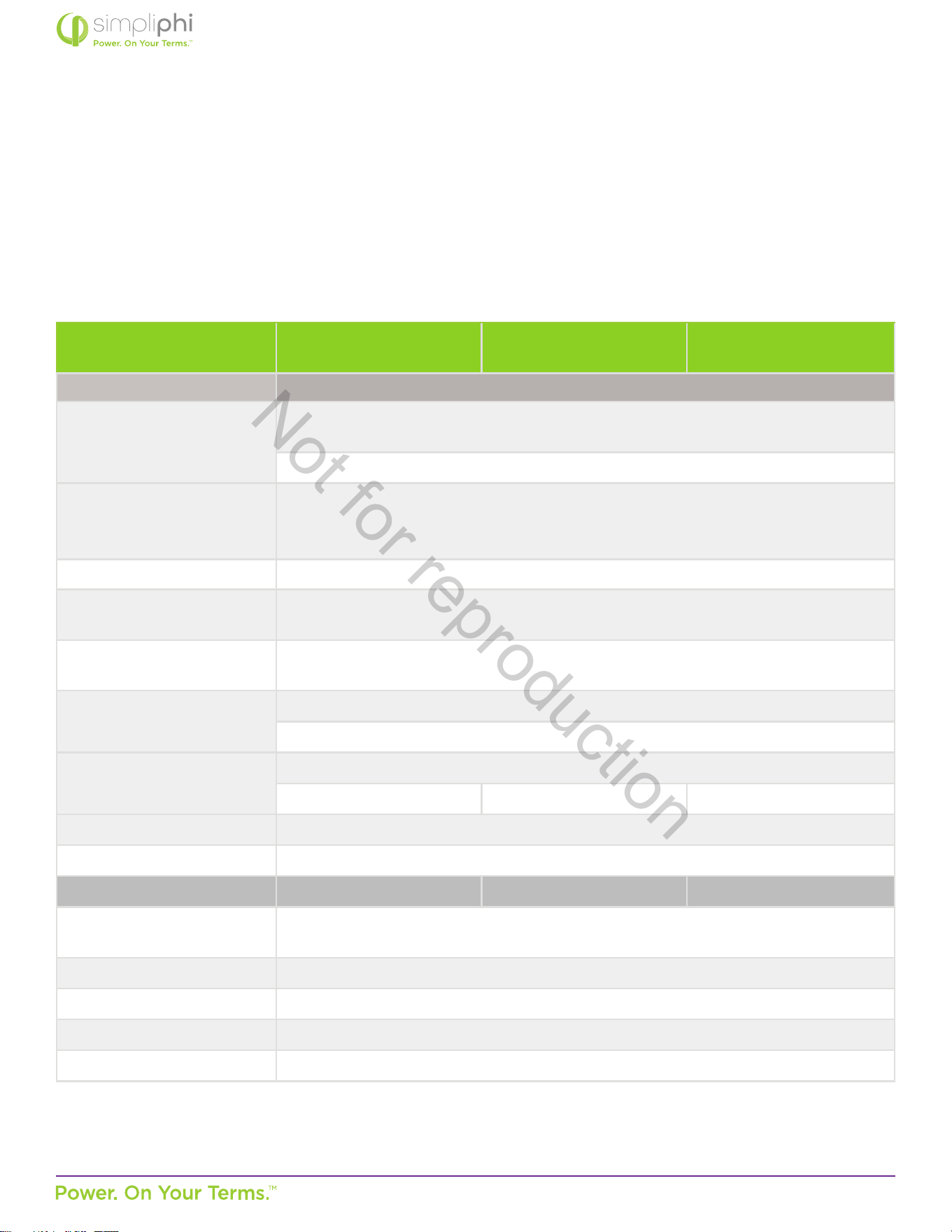
Table 4.0 –AccESS Sol-Ark System Grid Sengs
System Setup > Baery Setup
80% DoD
(10,000 cycles)
90% DoD
(5,000 cycles)
100% DoD
(3,500 cycles)
> Limiter Tab
Grid Sell
check this box when exporng solar PV power to the grid
(Net Energy Metering agreement required)
set the numerical value to the maximum number of exporng Was
Limited Power to Home
check this box when powering both the essenal loads sub-panel and
the main house breaker panel using solar and/or baery,
without exporng energy to the grid (limiter sensors required)
Limited Power to Load check this box when powering the essenal loads sub-panel using solar and/or baery
Time of Use Selling
check this box when discharging the baeries during set mes
(either the Grid Sell or Limited Power to Home box must also be checked)
Time
sets the me at which the baeries discharge to power both the essenal loads sub-panel
and the main house breaker panel (limiter sensors required)
Power (W)
sets the maximum amount of power discharged from the baeries during the set me
do not exceed the Waage values listed in Tables 2 or 3 above
Ba
the percentage SoC to which the baeries discharge during the set me
20% 10% 0%
Grid Charge check this box to allow for grid-to-baery charging during the set me
GEN check this box to allow for gen-to-baery charging during the set me
> Sell Control Tab 80% DoD 90% DoD 100% DoD
General Standard
check this box when a generator is wired to the Grid Input
or to use the Protect Param sengs listed in the Grid Input tab
UL 1741 & IEEE 1547 check this box for grid sell compliant funconality (default)
CA Rule 21 check this box for compliance with CA Rule 21
UL 1741SA check this box for compliance with HECO Rule 14H and/or PREPA
GEN connect to Grid input check this box when a generator is wired to the Grid Input
Not for reproduction
© SIMPLIPHI POWER, INC.
SIMPLIPHIPOWER.COM | 805-640-6700 | BSREV202111141140
47
MODEL NO. 050000, 050001
System Setup > Baery Setup
80% DoD
(10,000 cycles)
90% DoD
(5,000 cycles)
100% DoD
(3,500 cycles)
> Grid Input Tab
Grid Frequency select 50 Hz or 60 Hz
Grid Type
select 120/240V split phase (North America),
or contact SimpliPhi to special-order 220V single phase or 120/208V 3 phase
Protect Param
eave as default values when UL1741 & IEEE 1547 are enabled
frequency values may change when a generator is wired to the Grid Input
> FreqVolt tab refer to the Sol-Ark Manual for Puerto Rico or Kauai-specic sengs
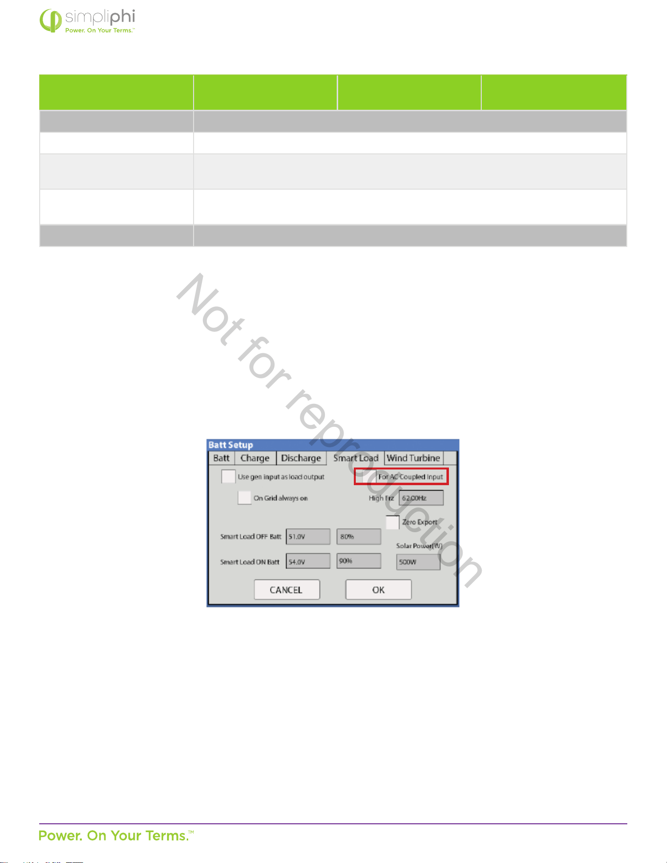
AC Coupled
In an AC Coupled system setup, the grid-e inverter(s) output – string or micro-inverters – is wired to the SolArk’s Generator
Input (50A double-pole breaker) and the For Micro inverter input box in the Smart Load tab of the Baery Setup menu must be
checked:
Figure 22 – Smart Load Tab in Ba Setup Menu
The Sol-Ark-12K is limited to 9.6 kW of AC Coupled solar. AC Coupled systems can operate in Grid Sell / Grid-Tied with Baery
Backup, Limited to Home, Limited to Load, or Time of Use Selling modes.
Not for reproduction

© SIMPLIPHI POWER, INC.
SIMPLIPHIPOWER.COM | 805-640-6700 | BSREV202111141140
48
MODEL NO. 050000, 050001
Grid Sell / Grid-Tied with Baery Backup
A net energy metering agreement with the ulity company is required in order to sell energy from the solar PV array to the grid.
In this mode, the Sol-Ark priorizes powering all loads (on both the essenal loads sub-panel and the main house breaker panel)
from solar PV rst (if available), then (2) grid, (3) generator, and (4) baeries.
In the event of a grid failure, the baeries will power the essenal loads sub-panel only. Take care to size the baery bank;
accordingly, in a grid failure scenario, the Sol-Ark does not limit the baeries’ maximum current output. The maximum power
draw (kW) on the essenal loads sub-panel should not exceed the maximum connuous discharge rate of the PHI baery bank.
Refer to the Discharge Calculaon in Secon 3 of this Guide:
Discharge Example:
• Circuits on the essenal loads sub-panel amount to a maximum potenal power draw of 37.5 Amps
at 240 VAC, or 9 kW
AC
• Sol-Ark-12K inverter DC-to-AC eciency is 96.5%
• PHI 3.8 kWh-51.2Vnom baery has a maximum connuous discharge rate of 1.92 kW
DC
A properly sized PHI baery bank based on the maximum draw of the essenal loads sub-panel has a minimum of 5 baeries,
even in this Grid-Tied with Baery Backup applicaon. Note also that during a grid failure, the essenal loads’ maximum energy
draw (kWh) is also limited by the baery bank’s capacity.
Limited to Home
Checking the Limited power to Home box in the Limiter tab of the Sol-Ark’s Grid Setup / Grid Param menu allows for all loads*
(on both the essenal loads sub-panel and the main house breaker panel) to be powered using the connected solar PV and/
or baeries. The Sol-Ark priorizes powering these loads from solar PV rst (if available), then (2) grid, (3) generator, and (4)
baeries. To priorize the baeries’ use over the grid or generator during specic set mes, also use the Time of Use Selling
mode.
*While the Limited to Home mode allows for all loads to be powered using solar PV and/or baeries, the SolArk priorizes
powering loads on the essenal loads sub-panel rst, and loads on the main house breaker panel are oset by solar (and/or
baeries, during Time of Use Selling mode mes) as much as possible. If the loads’ draw exceeds the available power from the
solar PV array and (with Time of Use Selling mode also in play) the baeries have also discharged to their minimum programmed
SoC percentage level, the Sol-Ark will then resort to powering loads using grid power.
CAUTION: In Limited to Home mode, limiter sensors are required to ensure that the home’s main breaker
panel circuits are powered without exporng energy to the grid.
Not for reproduction
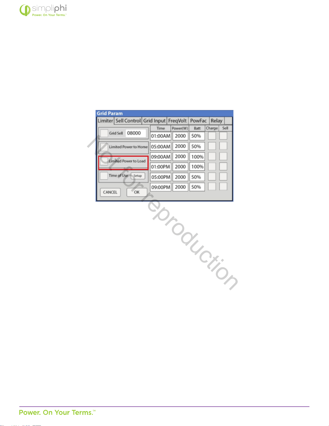
© SIMPLIPHI POWER, INC.
SIMPLIPHIPOWER.COM | 805-640-6700 | BSREV202111141140
49
MODEL NO. 050000, 050001
Limited to Load
Checking the Limited power to load box in the Limiter tab of the Sol-Ark’s Grid Setup / Grid Param menu discharges the baery
to power the essenal loads sub-panel’s loads. The Limited to Load mode does not allow for any solar or baery energy to
power the main house breaker panel and it does not allow for any solar or baery energy to be exported to the grid.
Figure 23.0 – Limiter Tab in Grid Setup Menu
Time of Use Selling / Energy Arbitrage
Discharge baeries to power circuits during specic set mes. Program these mes to coincide with the ulity company’s peak
pricing mes to avoid high energy charges from the ulity.
Homeowners who have a net energy metering agreement with the ulity company can use both Grid Sell and Time of Use
Selling modes to sell solar PV and baery energy (unl the minimum programmed SoC percentage level) back to the grid
during peak sun-hour mes and then discharge the baeries during programmed mes, usually in the aernoon and evening.
Depending on whether Limited Power to Load or Limited Power to Home is enabled, the baeries will power either the
essenal loads sub-panel only (Limited to Load) or the essenal loads sub-panel and the main house breaker panel (Limited to
Home) during the Time of Use Selling me period. Make sure to size the baery accordingly. (Refer to the Discharge Example in
the Grid Sell / Grid-Tied with Baery Backup secon of this Guide for baery bank sizing when baeries power the essenal
loads sub-panel only. Refer to the Discharge Example in Secon 3 of this Guide for baery bank sizing when the baeries power
both the essenal loads sub-panel and the main house breaker panel.)
Homeowners who do not have a net energy metering agreement use both Limited Power to Home and Time of Use Selling
modes to priorize powering all loads (circuits both on the essenal loads sub-panel and the main house breaker panel) from
the solar and/or baeries during programmed mes. Refer to the Discharge Example in Secon 3 of this Guide for baery bank
sizing when the baeries power both the essenal loads sub-panel and the main house breaker panel.
During Time of Use Selling mes, loads are powered from solar rst (if available), baeries second, and the grid third (if baeries
have discharged to their programmed minimum SoC percentage level).
Not for reproduction
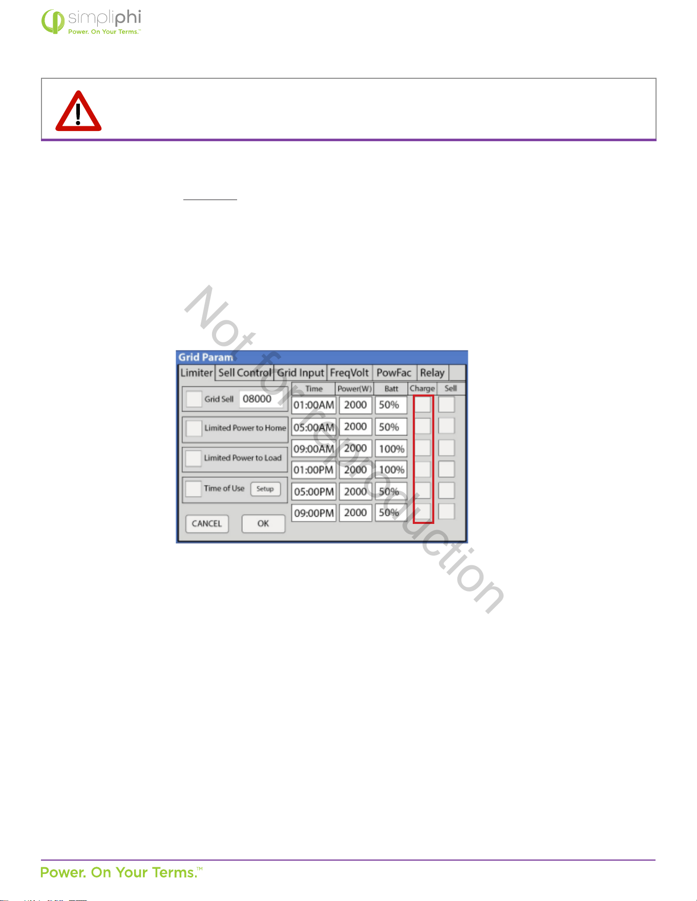
© SIMPLIPHI POWER, INC.
SIMPLIPHIPOWER.COM | 805-640-6700 | BSREV202111141140
50
MODEL NO. 050000, 050001
NOTE: Either the Grid Sell or the Limited Power to Home mode (check the appropriate box in the Grid Setup /
Grid Param menu) must be used in conjuncon with Time of Use Selling.
Make sure the Charge box is unchecked during peak pricing mes so that the baeries do not charge when energy from the
ulity company is most expensive (see Figure 24).
Figure 24.0 – Limiter Tab in Grid Setup Menu
O-Grid
The Sol-Ark automacally operates in O-Grid mode when it does not detect a grid connecon. In an O-Grid system setup, all
the home’s loads are connected to the Sol-Ark’s Load Output (63A double-pole breaker).
Do not use the Sol-Ark’s Grid Sell and Limited to Home modes in an o-grid system setup. Check the Limited Power to Load
box in the Limiter tab of the Sol-Ark’s Grid Setup / Grid Param menu to allow for the baeries’ power to discharge to the
connected loads.
Not for reproduction
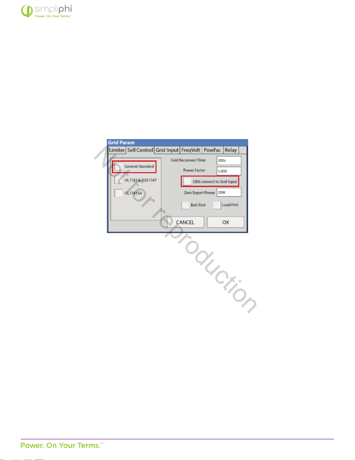
© SIMPLIPHI POWER, INC.
SIMPLIPHIPOWER.COM | 805-640-6700 | BSREV202111141140
51
MODEL NO. 050000, 050001
Generators
The Sol-Ark’s built-in Auto Generator Start funcons as a 2-wire automac switch.
The Sol-Ark’s Grid Input breaker can be used as the generator’s input breaker. In this scenario, check the General Standard box
and the GEN connect to Grid input box in the Grid Param menu’s Sell Control tab:
Figure 25.0 – Sell Control Tab in Grid Setup Menu
Not for reproduction
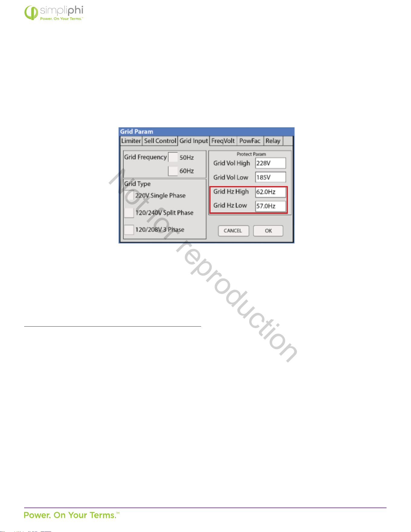
© SIMPLIPHI POWER, INC.
SIMPLIPHIPOWER.COM | 805-640-6700 | BSREV202111141140
52
MODEL NO. 050000, 050001
Due to the fact that many generators’ output frequency is usually less precise than the grid’s, the frequency parameters in the
Grid Param menu’s Grid Input tab may also need adjustment to accommodate a wider frequency range:
Figure 26.0 – Grid Input Tab in Grid Setup Menu
Homeowners who wish to include a grid connecon, generator, and Smart Load funconality can install a transfer switch
allowing for either grid or generator to connect to the Sol-Ark’s Grid Input. This frees up the SolArk’s Generator Input to be used
as an output for Smart Loads (see the following Smart Loads secon for more details).
In an AC Coupled system setup that includes a generator, using a transfer switch for a grid-or-generator connecon to the Sol-
Ark’s Grid Input also frees up the Sol-Ark Generator Input for connecon to the AC Coupled solar PV array.
If the system includes both a generator and a grid connecon, limiter sensors are required. While smaller generators (less than
10 kW) can be wired to the Sol-Ark’s Generator Input, Sol-Ark recommends wiring larger generators to a whole home transfer
switch instead of using the inverter’s Generator Input.
Not for reproduction
© SIMPLIPHI POWER, INC.
SIMPLIPHIPOWER.COM | 805-640-6700 | BSREV202111141140
53
MODEL NO. 050000, 050001
Smart Load
The Smart Load feature allows the homeowner to run higher power non-essenal appliances (hot water, dehumidier, heat
pump, irrigaon pump, etc.) on solar when excess solar power is available. This setup involves connecng these higher power
non-essenal loads to the Sol-Ark’s Generator Input. To parally protect the baeries against over-discharge, set the Smart
Load O Ba and Smart Load ON Ba parameters to the baeries’ acceptable SoC percentage range while in this mode.
However, note that no programmable parameter exists to regulate the baeries’ over-discharge from a current perspecve.
For example, an o-grid system with home loads totaling a maximum instantaneous power draw of 8 kW might include 5 PHI 3.8
baeries, with a maximum combined connuous power output of 9.6 kW
DC
/ 9.264 kW
AC
. With both the Smart Load and Limited
to Load modes enabled and the Smart Load ON Ba parameter set to 100% SoC, the Sol-Ark will begin powering the Smart
Loads (in addion to all the home loads) when the baeries are at 100% SoC. If the combined power draw exceeds 9.264 kW
AC,
(38.6 Amps at 240V
AC
), the baeries will then be operang beyond their maximum connuous power output capabilies. While
the baeries have a maximum surge discharge capability of 80 Amps DC per baery (20.48 kW
DC
/ 19.76 kW
AC
for the 5-baery
bank), the baeries cannot surge at this power level for more than 10 minutes. A combined load drawing more than 9.264 kW
AC
for more than 10 minutes will very likely result in the baeries’ SoC level reaching the Smart Load OFF Ba parameter, if it is set
to 95%. However, feel free to reach out SimpliPhi Power Technical Support (techsupport@simpliphipower.com) if the Smart Load
feature will be used and baery bank sizing claricaon according to Smart Load-specic loads needs to be claried.
Note that in a grid-connected system that ulizes the Smart Load feature, the Waage value to the right of the Smart Load ON
Ba parameter in the Smart Load menu tab (see Figure 5) represents the minimum power required of the solar PV array before
the Smart Loads are powered. Therefore, that Solar PV Waage value can be added to the baery bank’s maximum output
power rang when comparing maximum available solar and baery power available, against the Smart Load power draw:
Smart Load Draw (kW) ≤ Solar PV (kW) + Baery Bank MAX Output Power (kW).
CAUTION: Smart Loads’ maximum power draw cannot exceed the Generator Input breaker’s
50 Amp / 240VAC rang.
6.0 – SimpliPhi Technical Support
For technical support related to your AccESS, please contact us as follows:
805.640.6700
techsupport@simpliphipower.com
Not for reproduction
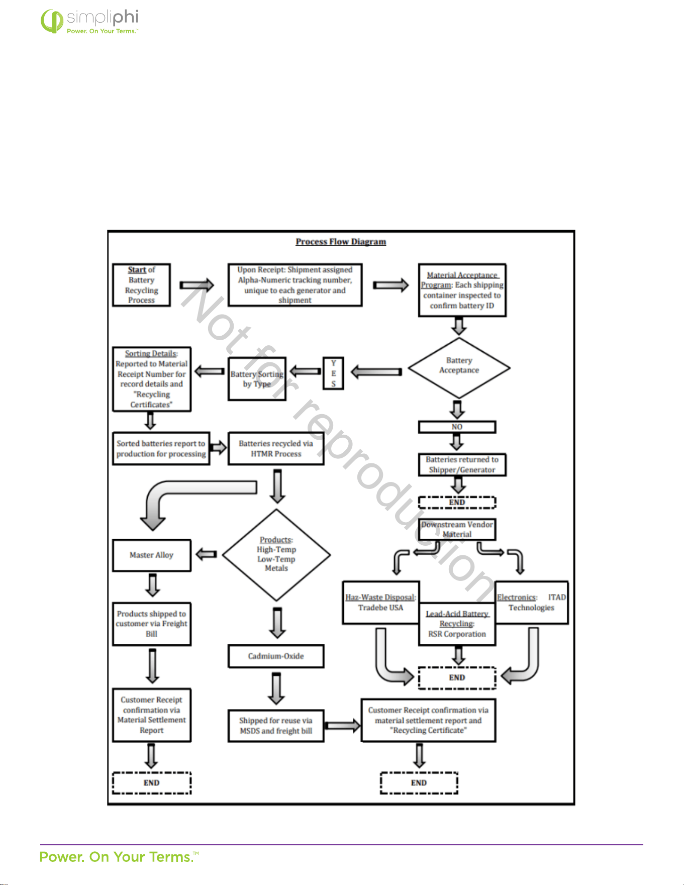
© SIMPLIPHI POWER, INC.
SIMPLIPHIPOWER.COM | 805-640-6700 | BSREV202111141140
54
MODEL NO. 050000, 050001
7.0 – Baery Recycling
Our recycling company recycle majority of our baery parts, cells and support business and retail customers alike by keeping
them in full compliance with federal, state, municipal, EPA and DOT regulaons governing the recycling of waste baeries and
select electronics.
By recycling LiFePo4 baeries, we reduce waste in our landlls, stop harmful chemicals from contaminang our soil and water,
and preserve our environment by decreasing the need for new raw materials from the Earth.
Not for reproduction
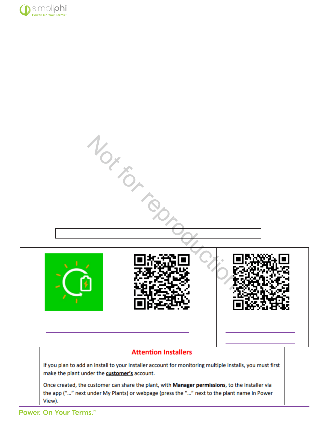
© SIMPLIPHI POWER, INC.
SIMPLIPHIPOWER.COM | 805-640-6700 | BSREV202111141140
55
MODEL NO. 050000, 050001
Appendix A: Sol-Ark WiFi Setup
Sol-Ark-12K Manual Excerpt (pg. 25-29)
a. Ethernet Dongle
i. Open Dongle housing
ii. Thread ethernet cable through provided opening and plug into the RJ45 port
iii. Reassemble the dongle housing
iv. Plug dongle into Sol-Ark and secure with screws
v. If all is well, you will see solid red and green lights
vi. Register your dongle via the app or www.mysol-ark.com
b. WIFI (Via Cell Phone or computer)
i. Plug WIFI dongle into Sol-Ark
ii. Using your device look for WIFI networks and select the one that matches the S/N number on
your dongle or the one that starts with “EAP” or “E470-####-####”
• Password: 12345678
iii. Once Connected to the Dongle
• Follow this instrucon on the following pages
Once Setup is complete, Dongle will have a solid green LED and a solid Red light
..
iPhone:
hps://apps.apple.com/lk/app/powerview-pro/id1247121391
Android:
hps://play.google.com/store/
apps/details?id=com.elinter.app.
powerview&hl=en_US&gl=US
Not for reproduction
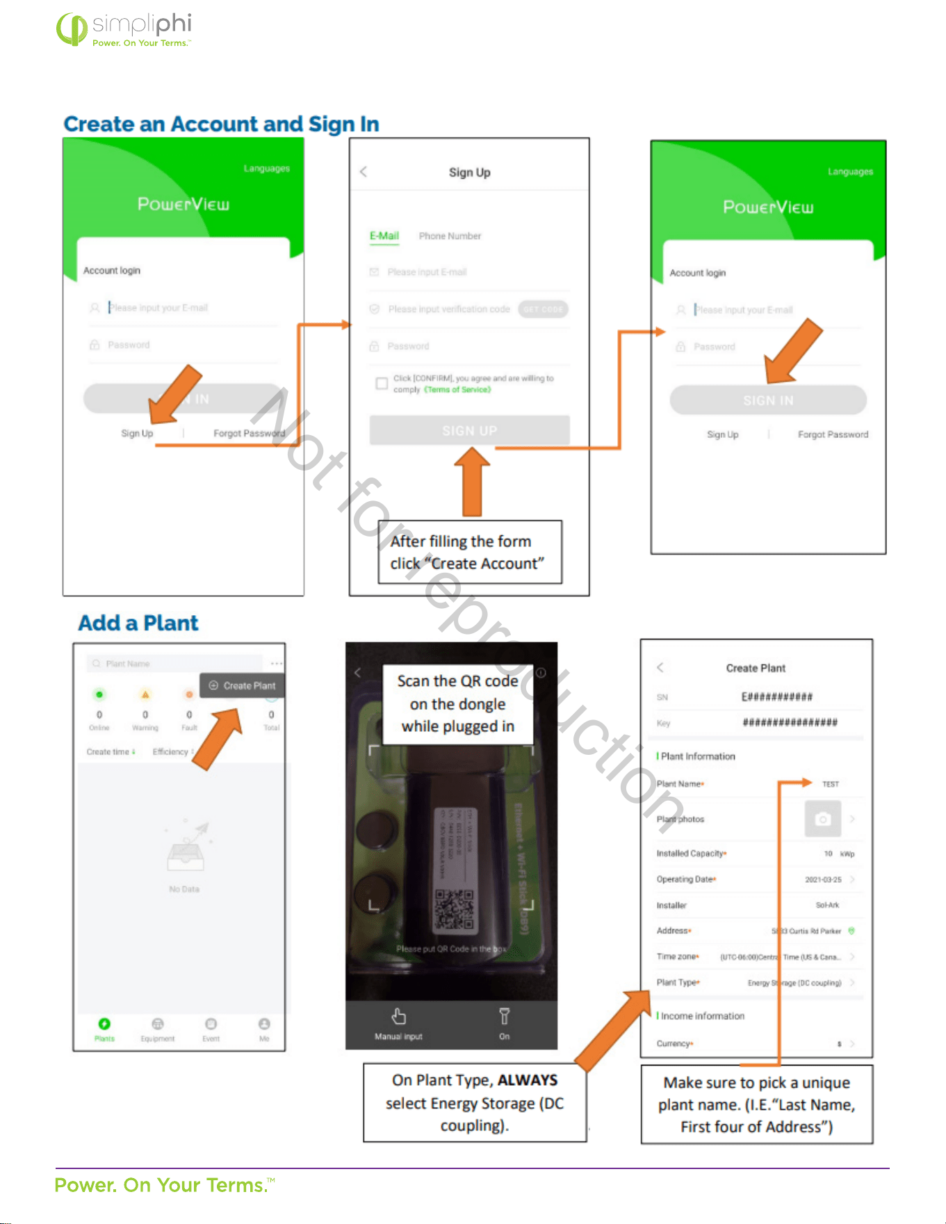
© SIMPLIPHI POWER, INC.
SIMPLIPHIPOWER.COM | 805-640-6700 | BSREV202111141140
56
MODEL NO. 050000, 050001
Not for reproduction
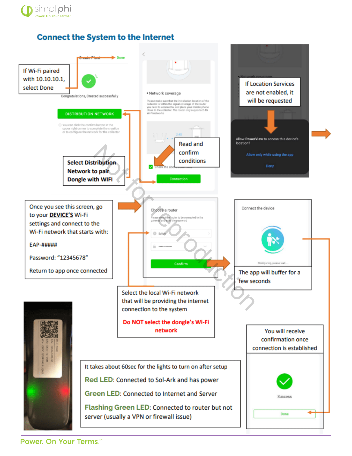
© SIMPLIPHI POWER, INC.
SIMPLIPHIPOWER.COM | 805-640-6700 | BSREV202111141140
57
MODEL NO. 050000, 050001
Not for reproduction
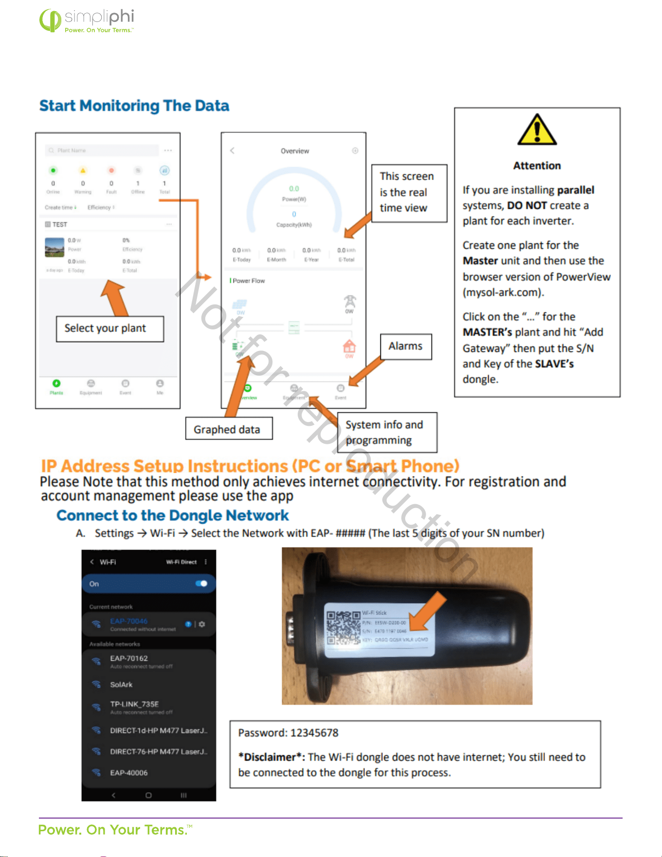
© SIMPLIPHI POWER, INC.
SIMPLIPHIPOWER.COM | 805-640-6700 | BSREV202111141140
58
MODEL NO. 050000, 050001
Not for reproduction

© SIMPLIPHI POWER, INC.
SIMPLIPHIPOWER.COM | 805-640-6700 | BSREV202111141140
59
MODEL NO. 050000, 050001
Not for reproduction
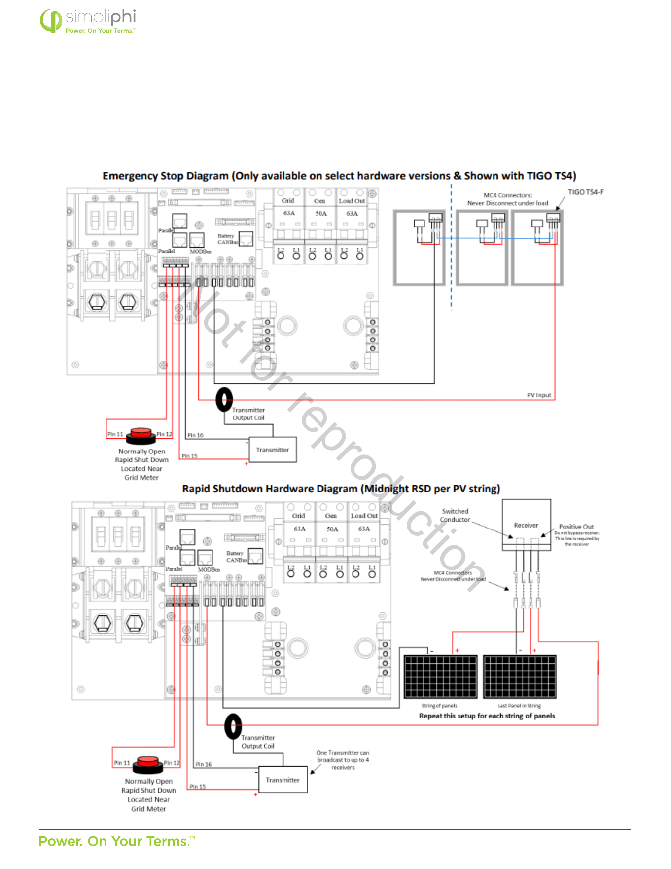
© SIMPLIPHI POWER, INC.
SIMPLIPHIPOWER.COM | 805-640-6700 | BSREV202111141140
60
MODEL NO. 050000, 050001
Appendix B: Rapid Shutdown Compliance
Sol-Ark-12K Manual Excerpt
Not for reproduction

© SIMPLIPHI POWER, INC.
SIMPLIPHIPOWER.COM | 805-640-6700 | BSREV202111141140
61
MODEL NO. 050000, 050001
Not for reproduction