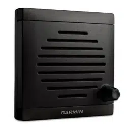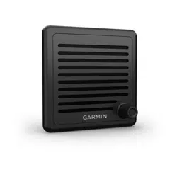
ACTIVE SPEAKER
INSTALLATION INSTRUCTIONS
Important Safety Information
CAUTION
Always wear safety goggles, ear protection, and a dust mask when drilling, cutting, or sanding.
NOTICE
When drilling or cutting, always check what is on the opposite side of the surface.
Tools Needed
• Pencil
• Drill
• 3mm (
1
/
8
in.) drill bit
• 13mm (
1
/
2
in.) drill bit
• Phillips screwdriver
• Rotary cutting tool or jigsaw
• Marine sealant (optional)
Mounting Considerations
NOTICE
This device should be mounted in a location that is not exposed to extreme temperatures or conditions. The
temperature range for this device is listed in the product specifications. Extended exposure to temperatures
exceeding the specified temperature range, in storage or operating conditions, may cause device failure.
Extreme-temperature-induced damage and related consequences are not covered by the warranty.
When selecting a mounting location for the active speaker, observe these considerations.
• To avoid interference with a magnetic compass, do not install the active speaker closer than 50cm (19.6in.)
to a compass.
• You must install the active speaker inline with a GHS
™
11 handset.
• You will need an extension cable (not included) to connect the active speaker to the VHF radio. You can use
the 10 m (32 ft.) extension cable that comes with the GHS 11 handset, and connect the handset to the cable
that is built into the active speaker, or purchase an extension cable separately (Extension Cables, page4).
When selecting a mounting location, make sure your extension cable is long enough to reach it from your
VHF radio black box.
• You must install the active speaker within 1.2m (48in.) of the location you want to connect the GHS 11
handset.
GUID-8F579D6D-A1E6-417B-A641-566579A3A9BF v3August 2023
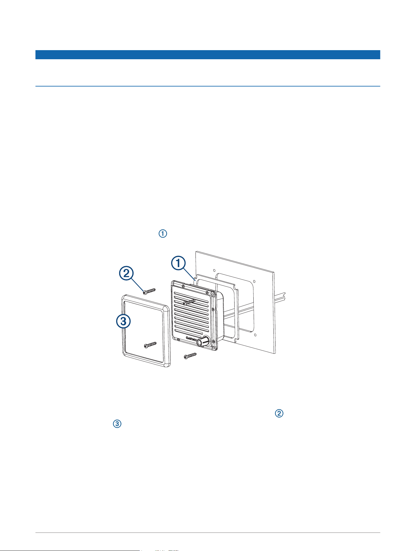
Mounting the Active Speaker
NOTICE
Be careful when cutting the hole to mount the speaker. There is only a small amount of clearance between the
case and the mounting holes, and cutting the hole too large could compromise the stability of the speaker after
it is mounted.
Before you can mount the speaker, you must select a mounting location.
1 Trim the template and make sure it fits at the mounting location.
2 Secure the template to the mounting surface.
3 Using a 13mm (
1
/
2
in.) drill bit, drill a hole inside the corner of the line on the template to prepare the
mounting surface for cutting.
4 Using a rotary-cutting tool or jigsaw, cut the mounting surface along the inside of the dashed line on the
template.
5 Place the speaker in the cutout to test the fit.
6 If necessary, use a file and sandpaper to refine the size of the cutout.
7 After the speaker fits correctly in the cutout, ensure the mounting holes on the speaker line up with the pilot
holes on the template.
8 If the mounting holes on the speaker do not line up, mark the new pilot-hole locations.
9 Using a 3mm (
1
/
8
in.) drill bit, drill the pilot holes.
10 Remove the template from the mounting surface.
11 Install the included mounting gasket on the back of the speaker.
12 Make the necessary wiring connections (Connecting the Active Speaker to the VHF Radio and Handset,
page3).
13 Place the speaker in the cutout.
14 Secure the speaker to the mounting surface using the included M4 screws .
15 Snap the screw cover in place.
2
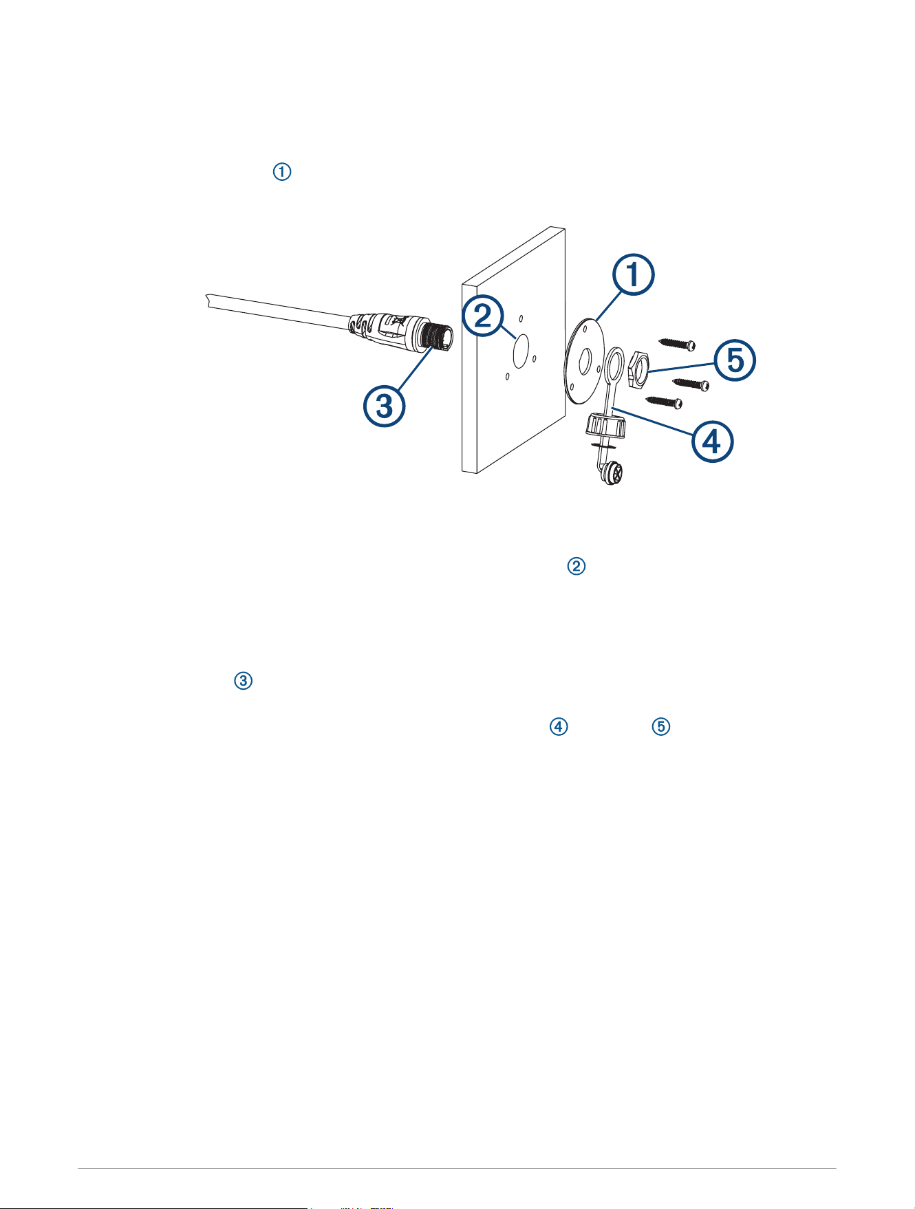
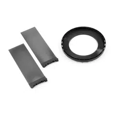
Installing the Handset Connector in the Mounting Surface
Before drilling a hole to mount the handset connector from the active speaker, you should mount the active
speaker and verify that the cable from the active speaker is long enough to reach the handset-connector
mounting location (Mounting the Active Speaker, page2).
1 Using the mounting plate as a template, trace the cable hole in the center of the mounting plate and mark
the screw locations.
2 Set the mounting plate aside.
Do not drill through the mounting plate.
3 Using a 22mm (
7
/
8
in.) drill bit or hole saw, drill the center cable hole in the mounting surface.
4 Using a 3mm (
1
/
8
in.) drill bit, drill the pilot holes.
5 Apply marine sealant between the mounting plate and the mounting surface to help seal the holes (optional).
6 Using the included screws, attach the mounting plate to the mounting surface.
7 Route the long cable from the active speaker to the connector mounting location.
8 Feed the connector through the back of the mounting surface.
9 Apply marine sealant around the connector in the mounting plate to help seal the hole (optional).
10 Secure the connector to the mounting plate using the weather cap and the nut .
Connecting the Active Speaker to the VHF Radio and Handset
Before you connect the active speaker to the VHF radio and handset, you should mount the active speaker
(Mounting Considerations, page1).
1 Route the female end of an extension cable (Extension Cables, page4) from the speaker mounting
location to the VHF radio.
2 Connect the extension cable to an open STATION port on the VHF radio.
3 Connect the male end of the extension cable to the short cable from the active speaker.
4 Route the long cable from the active speaker to the handset connector mounting location.
5 If necessary, install the cable from the active speaker in the mounting surface (Installing the Handset
Connector in the Mounting Surface, page3).
6 Connect the handset to the long cable from the active speaker.
3

Extension Cables
Extension cables are available from your Garmin
®
dealer.
Length Part Number
10 m (32 ft.)
1
010-12523-03
3 m (10 ft.) 010-12523-00
Specifications
Dimensions (H×W×D) 111 × 111 × 56.5mm (6.1 × 2.7 × 1.6in.)
Weight 349g (11.22oz.)
Temperature range
Operating: From -15° to 70°C (from 5° to 158°F)
Storage: From -20° to 70°C (from -4° to 158°F)
Compass-safe distance 50cm (19.6in.)
Water rating* IEC 60529 IPX7
Audio output power 2.5W nominal, 4W max.
*The device withstands incidental exposure to water of up to 1m for up to 30min. For more information, go to
www.garmin.com/waterrating.
© 2018 Garmin Ltd. or its subsidiaries
1
Comes with the GHS 11 handset.
© 2018 Garmin Ltd. or its subsidiaries
support.garmin.com