
Operation Manual
ELECTRIC CONCRETE
FLOOR GRINDER
MODEL NUMBER: TGDR10
To reduce the risk of injury, the user must read and understand the Operator’s
Manual before using this product. Save these instructions for future reference.

TABLE OF CONTENTS
2
1. SAFETY INFORMATION
2. OPERATING SAFETY
2.1 General Notes
2.2 Usage Safety
2.3 Service Safety
2.4 Electric Motors
2.5 Plugs
2.6 Extension Cables
2.7 NVR - No Volt Release
2.8 Health and Safety
3. EQUIPMENT PERFORMANCE
3.1 Tomahawk 10” Electric Floor Grinder
3.2 Electric Floor Grinder Features
3.3 Specifications
3.4 Max Cord Length
4. BEFORE STARTING THE MACHINE
5. STARTING THE MACHINE
6. OPERATING THE GRINDER
6.1 Stopping Grinder
7. STORAGE
8. DUST AND CRYSTALLINE SILICA WARNING
9. REPLACEMENT PARTS
10. TROUBLESHOOTING
11. MAINTENANCE
12. HOW TO REMOVE EPOXY FLOORING
12.1
Steps to Remove Epoxy Flooring
13. EQUIPMENT WARRANTY
14. PARTS MANUAL
15. TOMAHAWK CATALOG
4
5
5
5
6
7
7
7
7
8
8
8
8
9
9
9
9
10
10
10
11
12
13
14
15
15
16
17
26
Register Your Equipment
Thank you for purchasing TOMAHAWK® equipment! Your product is covered by the
TOMAHAWK® Warranty Policy, but in order to activate your warranty, we need you to register
your product. In addition to activating your equipment warranty, product registration will
grant you access to important product updates, streamlined customer service, and more.
INCLUDED WITH YOUR REGISTRATION
☑ Equipment Warranty Activation
☑ Product Updates
☑ Streamlined Customer Service
☑ Exclusive Discounts and Sales
STEPS TO REGISTER YOUR EQUIPMENT
1. Visit www.tomahawk-power.com
2. Choose “Product Registration” at the bottom of the page
3. Enter your equipment’s serial number to get started
4. Provide all required information
5. Submit Registration
Equipment Resources
TOMAHAWK® Customer Service doesn’t stop at checkout. We understand to keep a job-site
running smoothly - the proper equipment, spare parts, instruction manuals, and more are
needed at the drop of a hat. Visit www.tomahawk-power.com to gain access to the incredible
resources below.
How To Video Library
More of a visual person? Visit our Video Library for equipment
assembly instructions, troubleshooting tips, and more!
Found on each product listing or the Service Videos Page
Manual and Assembly Guide Library
Visit our Manual Library if you are looking for a lost
operations manual or a particular spare part?
Found on each product listing or the Tomahawk Manuals Page
Service Requests
In need of a quick fix or a service center referral? Submit a
Service Request and a Tomahawk Technician will respond
shortly to get you the help you need.
Choose “Service Request” at the bottom of www.tomahawk-power.com
3

4
This manual provides information and procedures to safely operate and maintain this
equipment. For your own safety and protection from injury, carefully read, understand, and
observe the safety instructions described in this manual.
Keep this manual or a copy of it with the equipment. If you lose this manual or need an
additional copy, please contact Tomahawk Power, LLC or visit www.tomahawk-power.com
This equipment is built with user safety in mind; however, it can present hazards if
improperly operated or serviced. Follow operating instructions carefully. If you have
questions about operating or servicing this equipment, contact TOMAHAWK®.
The information contained in this manual is based on equipment’s production at the time of
publication. TOMAHAWK® reserves the right to change any portion of this information
without notice.
No part of this publication may be reproduced in any form or by any means,
electronic or mechanical, including photocopying, without express written permission
from TOMAHAWK®.
Any type of reproduction or distribution not authorized by TOMAHAWK® represents an
infringement of valid copyrights and will be prosecuted. We expressly reserve the right to
make technical modifications, even without due notice, which aim at improving our
machines or their safety standards.
1. SAFETY INFORMATION
This manual contains DANGER, WARNING, CAUTION, and NOTE callouts which must be
followed to reduce the possibility of personal injury, damage to the equipment,
or improper service.
This is the safety alert symbol. It is used to alert you to potential personal injury
hazards. Obey all safety messages that follow this symbol to avoid possible injury
or death.
DANGER indicates an imminently hazardous situation which, if not avoided, will
result in death or serious injury.
WARNING indicates a potentially hazardous situation which, if not avoided, could
result in death or serious injury.
CAUTION indicates a potentially hazardous situation which, if not avoided, may
result in minor or moderate injury.
DANGER
WARNING
CAUTION

5
2. OPERATING SAFETY
Familiarity and proper training are required for the safe operation of equipment!
Equipment operated improperly or by untrained personnel can be dangerous! Read
the operating instructions contained in both this manual and the engine manual and
familiarize yourself with the location and proper use of all controls. Inexperienced operators
should receive instruction from someone familiar with the equipment before being allowed
to operate the machine.
2.1 General Notes
2.1.1 Individuals who operate this machine must be informed about the dangers related
to use of the machine.
2.1.2 Keep bystanders, especially children and animals, away from the work area.
2.1.3 The user is responsible for avoiding injury to third parties or damage to their property.
2.1.4 If you have any condition that might be aggravated by strenuous work, check with
your doctor before operating this power tool.
2.1.5 Minors should never be allowed to use this product.
2.2 Usage Safety
2.2.1 NEVER lend or rent your power tool without the instruction manual. Be sure that
anyone using it understands the information contained in this manual.
2.2.2 NEVER operate the machine if you are under the influence of any substance
(drugs, alcohol) which might impair vision, dexterity, or judgment.
2.2.3 NEVER operate the machine near open flame or explosive areas.
2.2.4 NEVER expose machine to wet conditions.
2.2.5 NEVER handle machine with wet hands.
2.2.6 ALWAYS wear ear protection.
2.2.7 OBSERVE all applicable local safety regulations, standards, and ordinances.
WARNING
Indicates a possibly dangerous situation. Where there is a risk of damaging the
machine or its individual components.
Indicates to read the Operation Manual. It is important that you read the operation
manual before first use and keep it in a safe place for future reference.

2.3 Service Safety
Poorly maintained equipment can become a safety hazard! In order for the
equipment to operate safely and properly over a long period of time, periodic
maintenance and occasional repairs are necessary.
2.3.1 DO NOT attempt to clean or service machine while it is running. Rotating parts can
cause severe injury.
2.3.2 ALWAYS replace worn or damaged components with spare parts designed and
recommended by TOMAHAWK®.
2.3.3 ALWAYS keep machine clean and labels legible. Replace all missing and hard-to-read
labels. Labels provide important operating instructions and warn of dangers and hazards.
2.3.4 This equipment is heavy and must not be lied single-handedly. Must be listed with
two people or use suitable liing equipment.
2.3.5 Cordon o the work area and keep members of the public and unauthorized personnel
at a safe distance.
2.3.6 Personal Protective Equipment (PPE) must be worn by the operator whenever this
equipment is being used.
2.3.7 Make sure you know how to safely switch this machine OFF before you switch it ON in
case you get into diiculty.
2.3.8 Always switch OFF and unplug the motor before transporting, moving it around the
site, or servicing it.
2.3.9 During use, the motor becomes very hot, allow the motor to cool before touching it.
Never leave the motor running and/or unattended.
2.3.10 NEVER remove or tamper with any guards fitted, they are there for your protection.
Always check that guards are in proper condition, if any are damaged or missing, DO NOT
USE THE MACHINE until the guard has been replaced or repaired.
2.3.11 NEVER pull or guide the machine using the cable and never pull on the cable to
diconnect the plug.
2.3.12 DO NOT operate the machine when you are ill, feeling tired, or when under the
influence of alcohol or drugs.
2.3.13 Ensure that any trailing cable is protected against damage and not liable to be tripped
over or trapped underneath the machine.
2.3.14 DO NOT use the Motor Guard as a Liing Point.
2.3.15 DO NOT Jet Wash the machine as this could result in serious injury or even death!
2.3.16 DO NOT use this machine in wet conditions. The electrical components of the
machine NEVER be exposed to water or liquid of any kind as this could result in serious
injury or even death!
WARNING
6

7
2.4 Electric Motors
All portable electric appliances are dangerous if abused. This machine will only operate on
one voltage. Check the power supply to ensure it corresponds to the voltage as stamped on
the motor. Make sure that the motor is switched OFF before you plug it into the power supply.
When using a portable transformer it must have a minimum output of 3.3kw and be
continuously rated. The symbols on the ON/OFF switch are 0=OFF and I=ON in accordance
with international standards.
2.5 Plugs
The following plug types are supplied/fitted to the product: 15 amp rated 120 volt plug type.
GREEN / YELLOW = GROUND, BLUE = NEUTRAL, BROWN = LIVE
The wire which is colored Green and Yellow must be connected to the terminal in the plug
marked E or colored Green and Yellow. The wire which is colored Brown must be connected
to the terminal in the plug marked L or colored Red. The wire which is colored Blue must be
connected to the terminal in the plug marked N or colored Black. Always ensure before
connecting to the supply that the supply voltage is the same as the rated voltage marked on
the motor
2.6 Extension Cables
If you need to use an extension cable it must be no longer than 25 meters (82 feet) in length.
The wire section must be 2.5mm2 on 240v and 2.5mm2 on 120v. Ensure that the extension
cable is carefully laid out avoiding liquids, sharp edges and places where vehicles might run
over it. Avoid allowing the extension cable to be trapped underneath the equipment. Unroll
it fully or it will overheat and could catch fire. Make sure that any extension cable
connections are dry and safe.
2.7 NVR - No Volt Release
The motors which are fitted to the machine are fitted with a NVR (No Volt Release) Switch.
This mean that if the power fails, the motor will not automatically restart when the power is
restored. The machine will need to be manually restarted.
DO NOT use an extension cable between the transformer and the power
supply. Always ensure that the cable between the 120v machine and
transformer is a minimum length of 10. Ensure cable is fitted with cable clip
to the operating handle at all times.
WARNING
THIS PRODUCT MUST BE GROUNDED
IMPORTANT: The wires in the mains lead are colored in accordance with the
following code:
WARNING
2.8 Health and Safety
2.8.1 PPE (Personal Protective Equipment)
Suitable PPE must be worn when using this equipment i.e. Safety Goggles, Gloves, Ear
Protection, Dust Mask, and Steel Toe capped footwear (with anti-slip soles for added
protection). Wear clothing suitable for the work you are doing. Always protect skin from
contact with concrete.
3. EQUIPMENT PERFORMANCE
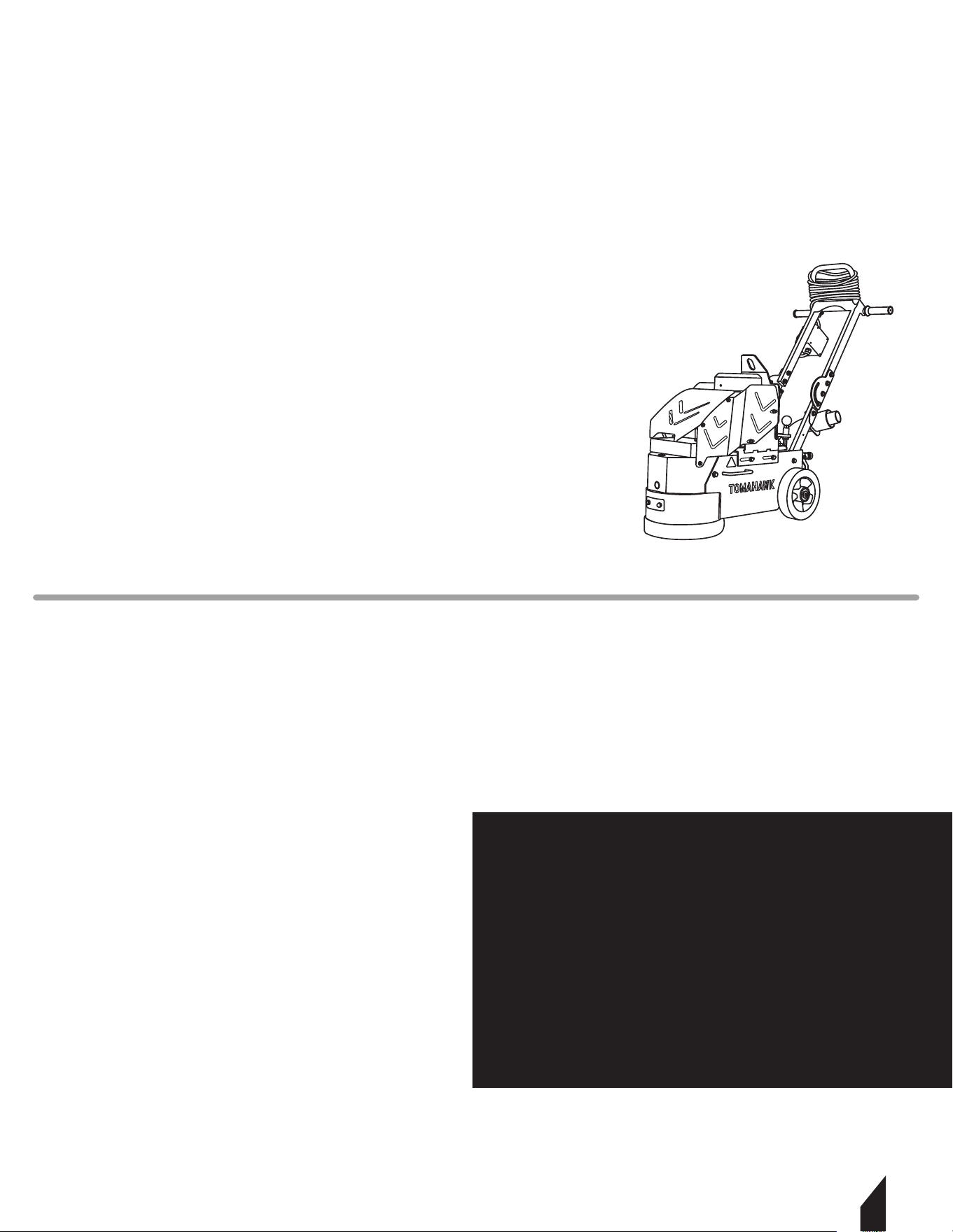
3.1 Tomahawk 10” Electric Floor Grinder
TOMAHAWK® Electric Floor Grinders remove surfaces up to 250 ²/hour – perfect for grinding
away imperfections, coatings, and leveling surfaces - leaving behind a smooth, textured, or
polished finish. Easy to operate with a flexible design – grind up tight against walls, doorways,
or columns. . Powered by a 1.5HP motor, this grinder only draws 18 amps making it suitable
for use with 120V household circuits and portable generators!
If any parts are missing or damaged, please contact TOMAHAWK® customer support by
email at support@tomahawk-power.com or call (866) 577-4476.
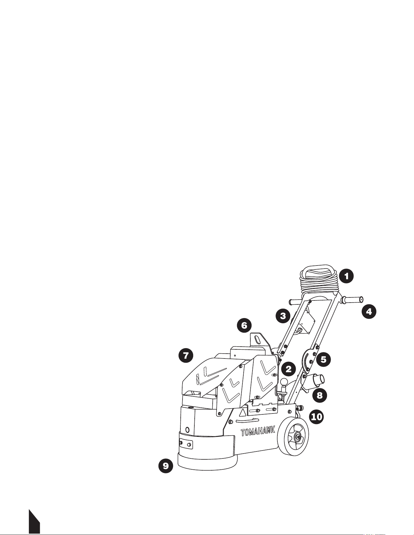
3.2 Electric Floor Grinder Features
10
8
1. Extension Power Cord
2. Leveling Knob
3. Power Switch
4. Bicycle Handles
5. Foldable Handles
6. Liing Hook
7. Robust Housing
8. Vacuum System
9. Velcro Dust Shroud
10. Hose Adapter
3.3 Specifications
3.4 Maximum Recommended Cord Length for TOMAHAWK® Equipment
Full Loaded Amps May Vary
9
Power
Belt
Size
Depth
Amps
RPMs
Cord Length
Wheel Diameter
Weight
Warranty
TGDR10 FLOOR GRINDER
1.5 HP
10" (25.4cm)
Std "V" Belt
1/32" per pass
11 A
1,725
18 (5.4m)
8" (20.3 cm)
151 lbs (68.4kg)
1 Year
THIS MODEL
115V
.5 - 2HP
230V
1.5 - 2HP
230V
3 - 5HP
230V
5HP
460V
5HP
230V
7.5HP
460V
7.5HP
230V
10HP
460V
10HP
12 Gauge
25'
CABLE
150'
CABLE
50'
CABLE
150'
CABLE
300'
CABLE
100'
CABLE
100'
CABLE
50'
CABLE
200'
CABLE
10 Gauge
50'
CABLE
200'
CABLE
100'
CABLE
200'
CABLE
N/A
150'
CABLE
150'
CABLE
100'
CABLE
300'
CABLE
8 Gauge
100'
CABLE
300'
CABLE
150'
CABLE
300'
CABLE
N/A
250'
CABLE
250'
CABLE
150'
CABLE
N/A
CABLE SIZE
SINGLE PHASE THREE PHASE
4. BEFORE STARTING THE MACHINE
4.1 Inspect the work surface for cracks, uneven joints and foreign objects such as nails,
screws and pipes. If the unit is used on said surfaces, damage to the blade and/or equipment
may result, which can also cause serious injury to the operator. Hazardous areas should be
properly identified, clearly marked and avoided.
4.2 Be sure the power switch is in the OFF position. Inspect the power and extension cords
before plugging into the power source. DO NOT use if either cord is frayed or showing wear.
4.3 Inspect the blade carefully before installing. The blade must be sharp
and properly installed.
4.4 Use only genuine blades. DO NOT use any questionable blades, as serious personal
injury and/or damage to property can result.
4.5 Adjust the height of the blade for the conditions of the job at hand.
4.6 When operating on carpet and sheet floors, pre-cut the material in a strip as wide as the
blade.
4.7 Make sure the diamond tooling is suitable for the material being ground and that the
tooling is correctly balanced.
4.8 Ensure that the grinding plates are in good condition and properly mounted. Never use
damaged tooling.
4.9 All counter sunk bolts must be tightened to specifications and firmly in place. Take periodic
breaks to ensure that bolts are properly tightened, as they can loosen during operation.
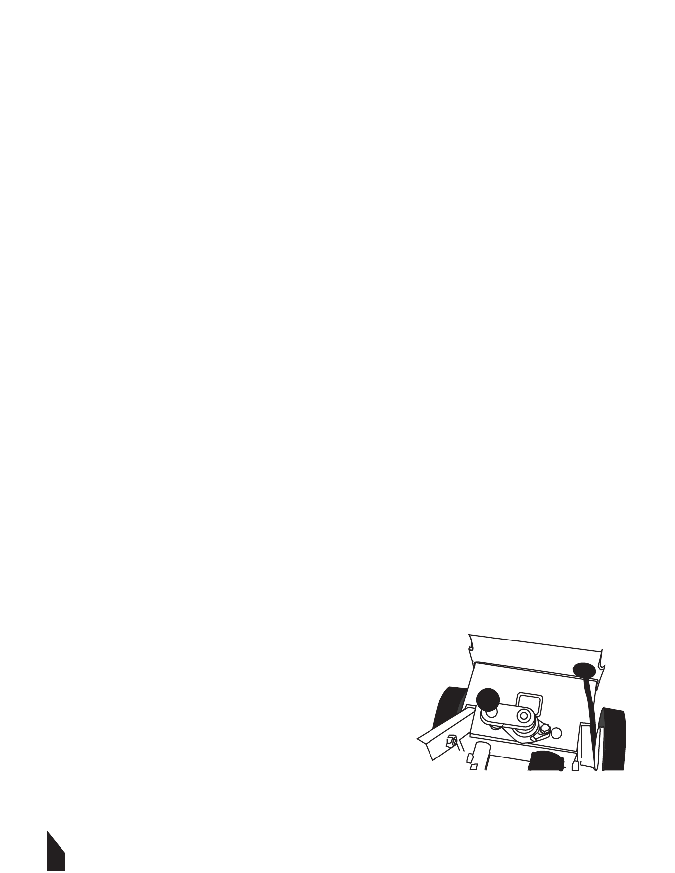
4.10 Check that the grinding plate is adjusted so that it sits
level on the work surface (use the bubble-level on the
machine as a reference in FIGURE 1).
5. STARTING THE MACHINE
5.1 Make sure the machine is clear of walls and/or
obstructions.
5.2 Tilt it back slightly to shi the weight onto the
wheels.
10
FIGURE 1
11
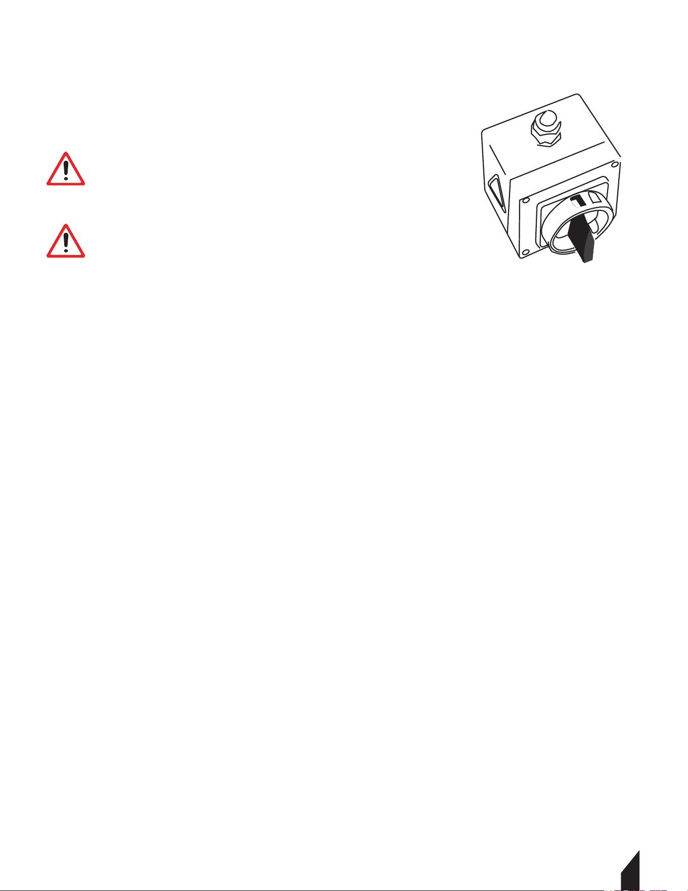
5.3 Plug in the machine.
5.4 Start the motor by turning the red switch on the starter box.
FIGURE 2.
6. OPERATING THE GRINDER
6.1.1 Raise the grinding plates from the floor.
6.1.2 Start the motor by turning the red switch on the starter box(FIGURE 2.). Lower the grinding
plate and begin grinding. Keep the grinding head moving side to side on the work surface to create
an evenly ground surface until the desired results are reached.
NOTE:The position of the axle may be adjusted as needed for leveling.
1. Adjust the vertical grinding position by loosening the level adjustment
fastener counter clockwise.
2. Liing the level adjustment handle raises the back end of the grinder.
3. Lowering the level adjustment handle lowers the back end of the grinder.
4. Use “bubble-level”, mounted on the machine as a reference.
5. Secure desired grinder position by tightening the level adjustment
fastener clockwise.
6.2 Stopping the Grinder
6.2.1 Turn the red switch on the start box counter clockwise.
6.3 STORAGE
6.3.1 Aer turning o the grinder clean the machine of all dust.
6.3.2 Aer cleaning fold the handles down and store away in a safe dry area.
6.3.3 The grinder should be stored on level ground. Be sure to secure the grinder
as necessary to avoid it from falling down.
WARNING
WARNING
BLADE IS EXTREMELY SHARP!
Wear heavy duty work gloves when changing the
blades and handle with care.
DO NOT FORCE THE MACHINE.
Shut OFF the machine before repositioning the
scraper for another pass.
FIGURE 2

12
7. DUST AND CRYSTALLINE SILICA WARNING
Grinding/cutting/drilling of masonry, concrete, metal and other materials can generate dust,
mists and fumes containing chemicals known to cause serious or fatal injury or illness, such
as respiratory disease, cancer, birth defects or other reproductive harm. If you are unfamiliar
with the risks associated with the particular process and/or material being cut or the
composition of the tool being used, review the material safety data sheets and/or consult
your employer, the manufacturers/suppliers, governmental agencies such as OSHA and
NIOSH and other sources on hazardous materials. California and some other authorities, for
instance, have published lists of substances known to cause cancer, reproductive toxicity, or
other harmful effects.
Control dust, mist and fumes at the source where possible. In this regard use good work
practices and follow the recommendations of the manufacturers/suppliers, OSHA/NIOSH,
and occupational and trade associations. Water should be used for dust suppression when
wet grinding/ cutting/drilling is feasible. When the hazards from inhalation of dust, mists
and fumes cannot be eliminated, the operator and any bystanders should always wear a
respirator approved by NIOSH/MSHA for the material being used.
Grinding/cutting/drilling of masonry, concrete and other materials with silica in their
composition may give off dust or mists containing crystalline silica. Silica is a basic
component of sand, quartz, brick clay, granite and numerous other minerals and rocks.
Repeated and/or substantial inhalation of airborne crystalline silica can cause serious or
fatal respiratory diseases, including silicosis. In addition, California and some other
authorities have listed respirable crystalline silica as a substance known to cause cancer.
When grinding/cutting/drilling such materials, always follow the respiratory precautions
mentioned above.
See more on the importance of dust prevention and silica warnings at osha.gov/silica.
WARNING
WARNING

13
8. BLADE OPTIONS
The grinder has additional assortment of blades available for use. Such as:
• 10" Grinding Wheel 20 Segments Concrete Floor Grinder Disc Blades
9. REPLACEMENT PARTS
9.1 For replacement parts and technical questions visit www.tomahawk-power.com.
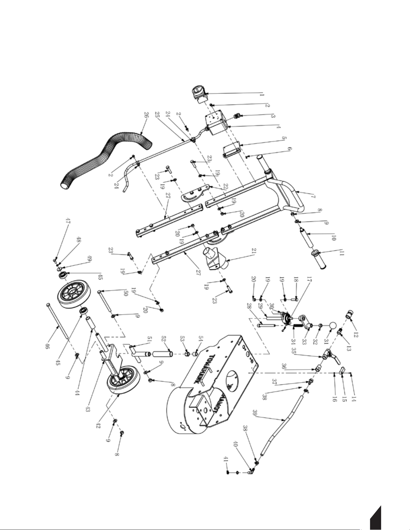
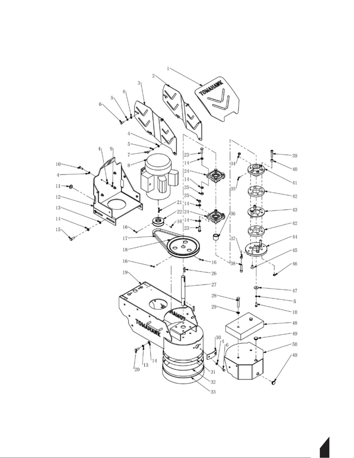
9.2 Not all equipment components are available for replacement. The illustrations
within this manual are a convenient reference to the location and position of parts
in the assembly sequence.
9.3 When ordering parts, the following may be required: equipment model number, serial
number/lot, date code, and description. The manufacturer reserves the right to make design
changes and/or improvements to equipment, parts, accessories, and manuals without
notice.
10. TROUBLESHOOTING
Grinder runs for short
time then stops
Grinder runs but does
not perform adequately
Grinder vibrates
during use
Grinding noise coming
from grinding head under
no-load operation
The electrical power
current limit screw is
not adjusted properly
Adjust the current limit
screw located in the
Schneider housing to the
appropriate setting
Grinding plates not
correctly balanced
Worn motor bearings
or drive coupling
Have machine evaluated
and serviced by
authorized service
professional
Replace grinding plates
Tooling is not matched to the
applicaon
Re-evaluate tooling
selection
PROBLEM POSSIBLE CAUSES SOLUTION
14
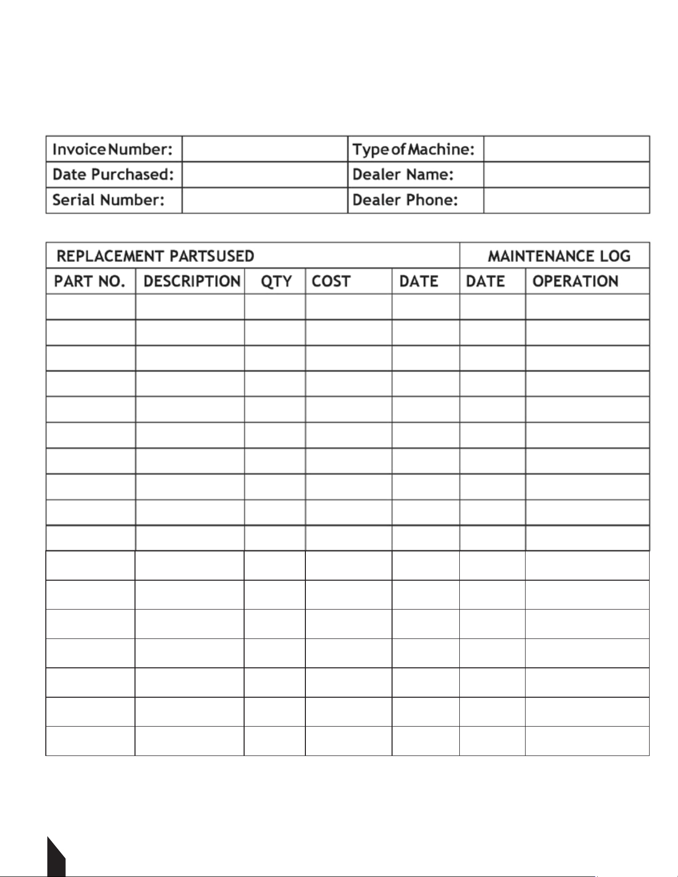
11. MAINTENANCE
For your convenience we have provided this space to record relevant data about your
TOMAHAWK® equipment.

15
12. HOW TO REMOVE EPOXY FLOORING
Removing epoxy flooring can be challenging, but a floor grinder makes the job
easier. Follow this concise guide on how to remove epoxy flooring using the
Tomahawk 10" Electric Floor Grinder.
12.1 Steps to Remove Epoxy Flooring
1. Preparation
• Safety Gear: Wear goggles, gloves, a dust mask, and ear protection.
• Clear the Area: Remove furniture and cover nearby items with plastic
sheeting.
• Inspect the Floor: Check for cracks or damage needing extra attention.
2. Set Up the Floor Grinder
• Select the Right Tools: Attach a diamond grinding disc to the
Tomahawk 10" Electric Floor Grinder.
• Connect Power Supply: Ensure the grinder is properly connected
to a power source.
3. Grinding the Epoxy Floor
• Start Grinding: Begin at one corner and work systematically across
the floor.
• Apply Even Pressure: Move the grinder back and forth, overlapping each
pass slightly.
• Monitor Progress: Check regularly to ensure even epoxy removal.
4. Clean Up
• Vacuum Debris: Use a high-powered vacuum to clean up dust and debris.
• Inspect the Surface: Ensure all epoxy is removed, re-grind if necessary.
5. Finishing Touches
• Final Clean: Wipe down the floor with a damp cloth to remove any
remaining dust.
• Prepare for New Flooring: The surface should now be smooth and
• ready for new flooring.
• Start Grinding: Begin at one corner and work systematically
across the floor.

16
13. EQUIPMENT WARRANTY
Your new TOMAHAWK® equipment is warranted to the original purchaser for a period of
one-year (12 months) from the original date of purchase. The TOMAHAWK® warranty is
against defects in design, materials and workmanship.
The following are not covered under the warranty:
13.1 Damage caused by abuse, misuse, dropping or other similar damage caused by or as a
result of failure to follow assembly, operation or user maintenance instructions.
13.2 Alterations, additions or repairs carried out by persons other than TOMAHAWK®
or their recognized agents.
13.3 Transportation or shipment costs to and from TOMAHAWK® or their recognized agents,
for repair or assessment against a warranty claim, on any machine.
13.4 Materials and/or labor costs to renew, repair or replace components due to fair wear
and tear.
13.5 TOMAHAWK® and/or their recognized agents, directors, employees or insurers will not
be held liable for consequential or other damages, losses or expenses in connection with or
by reason of or the inability to use the machine for any purpose.
Warranty Claims
Before submitting any warranty claim, you will need to register
your new TOMAHAWK® equipment through
www.tomahawk-power.com.
Follow the steps on page 3 or scan this QR codes to complete
the equipment registration. Aer registration is complete, all
warranty claims should firstly be directed to TOMAHAWK®
through the online Service Request form found at
www.tomahawk-power.com/pages/service-request.
17
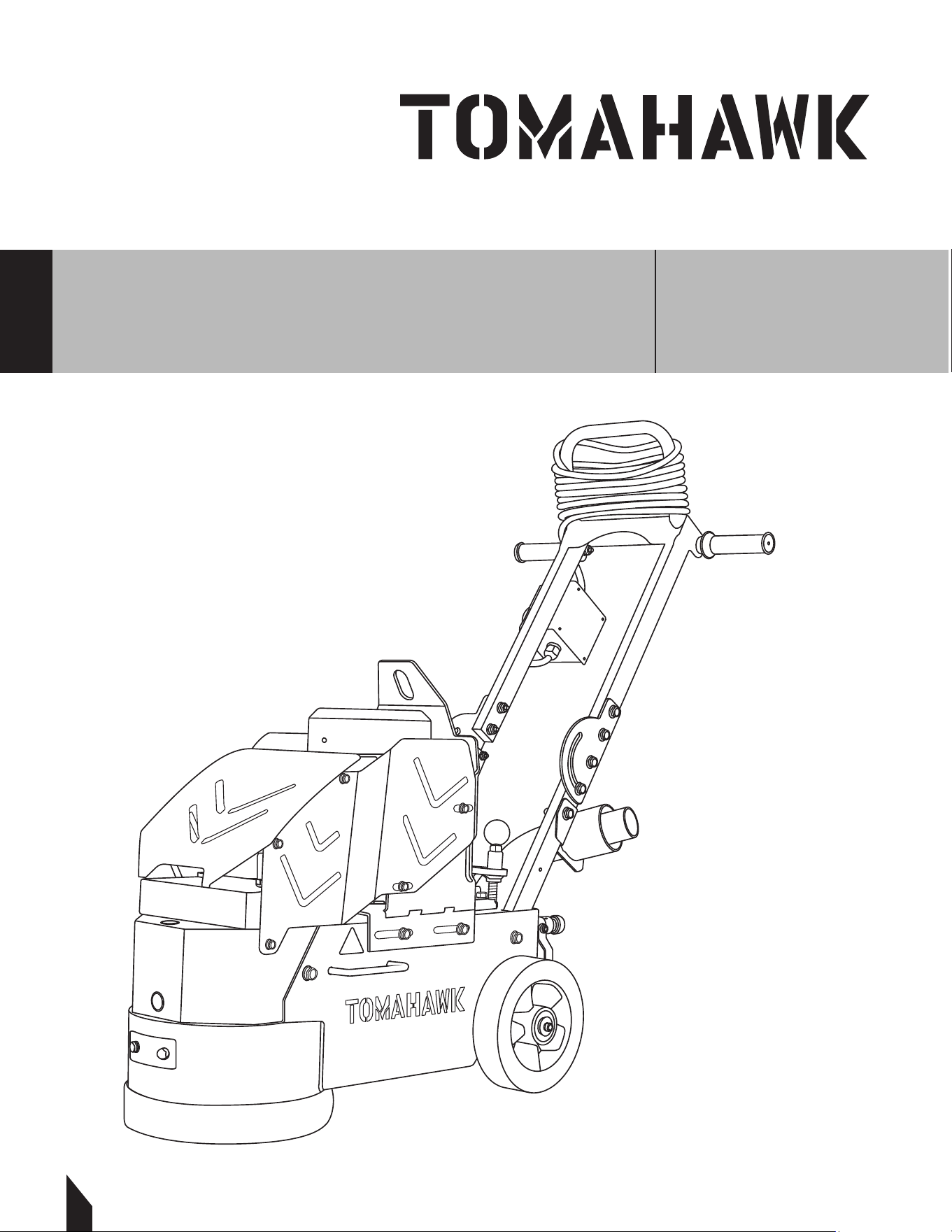
Parts Manual
ELECTRIC CONCRETE
FLOOR GRINDER
MODEL NUMBER: TGDR10
18
MAIN FRAME UNIT EXPLOSION

19
No. Description Part No. Qty
1 Switch 1510-00018-4 1
2 Bolt M6x12 15060122 4
3 Joint, Electrical Box 70000029 2
4 Electrical Box 1510-00024-4 1
5 Plate, Electrical Box 1510-00005-2 1
6 Bolt M4x8 16040801 4
7 Handle Assy. 1511-11000-3 1
8 Lock Nut M12 13120001 4
9 Washer M12 11120000 6
10 Handle Bar 1510-10000-3 2
11 Handle Grip 70260000 2
12 Joint 70000010 1
13 Adaptor 70000008 1
14 Bolt M3x12 16031201 2
15 Level Gauge 70000115 1
16 Lock Nut M3 13030001 2
17 Set Screw M8x10 16081005 1
18 Bolt M10x35 15100350 2
19 Washer M10 11100000 28
20 Lock Nut M10 13100001 13
21 Vac Port 1511-06000-3 1
22 Connecting Plate 1510-00019-2 2
23 Bolt M10x45 15100450 13
24 Clamp Φ12 70000100 2
25 Cable 1510-00022-4 1
26 Vac Bellow 1511-00029-1 1
27 Lower Bar 1510-01000-3 2
28 Allen Screw M12x110 161211003 1
29 Set Screw M16 1511-00025-1 1
30 Bearing UCFL203 21UCFL203-76.5 1
31 Knob M12 70000113 1
32 Nut M12 13120000 1
33 Adjustment Hand Wheel 1511-08000-3 1
34 Spring, Knob 1511-00026-4 1
35 Switch, Water Tank 2402-00077-4 1
36 Joint 12.7mm 70000114 1
37 Joint G1/2x12mm 70000105 1
38 Clamp Φ16 70000024 2
39 Water Pipe 1511-00031-1 1
40 Joint G1/4x12mm 70000116 1
41 Nut G1/4 131/40015 2
42 Wheel 200x50 24200504 2
43 Adjustment Panel 1511-03000-3 1
44 Spacer 1511-00024-1 2
45 Bearing 6204 216204-2R 4
46 Bolt M12x280 151228001 1
47 Bolt M8x20 15080200 2
48 Spring Washer M8 12080000 2
49 Washer M8x30x3 11083003 2
50 Bolt M12x160 15121601 1
51 Set Screw Shaft Sleeve 1511-05000-3 1
52 Dust Protector 1511-00033-1 1
53 Nut M16 13160000 1
54 Spacer, Set Screw 1511-00034-1 1
Main Frame
20
12. HOW TO REMOVE EPOXY FLOORING
Removing epoxy flooring can be challenging, but a floor grinder makes the job
easier. Follow this concise guide on how to remove epoxy flooring using the
Tomahawk 10" Electric Floor Grinder.
12.1 Steps to Remove Epoxy Flooring
1. Preparation
• Safety Gear: Wear goggles, gloves, a dust mask, and ear protection.
• Clear the Area: Remove furniture and cover nearby items with plastic
sheeting.
• Inspect the Floor: Check for cracks or damage needing extra attention.
2. Set Up the Floor Grinder
• Select the Right Tools: Attach a diamond grinding disc to the
Tomahawk 10" Electric Floor Grinder.
• Connect Power Supply: Ensure the grinder is properly connected
to a power source.
3. Grinding the Epoxy Floor
• Start Grinding: Begin at one corner and work systematically across
the floor.
• Apply Even Pressure: Move the grinder back and forth, overlapping each
pass slightly.
• Monitor Progress: Check regularly to ensure even epoxy removal.
4. Clean Up
• Vacuum Debris: Use a high-powered vacuum to clean up dust and debris.
• Inspect the Surface: Ensure all epoxy is removed, re-grind if necessary.
5. Finishing Touches
• Final Clean: Wipe down the floor with a damp cloth to remove any
remaining dust.
• Prepare for New Flooring: The surface should now be smooth and
• ready for new flooring.
• Start Grinding: Begin at one corner and work systematically
across the floor.
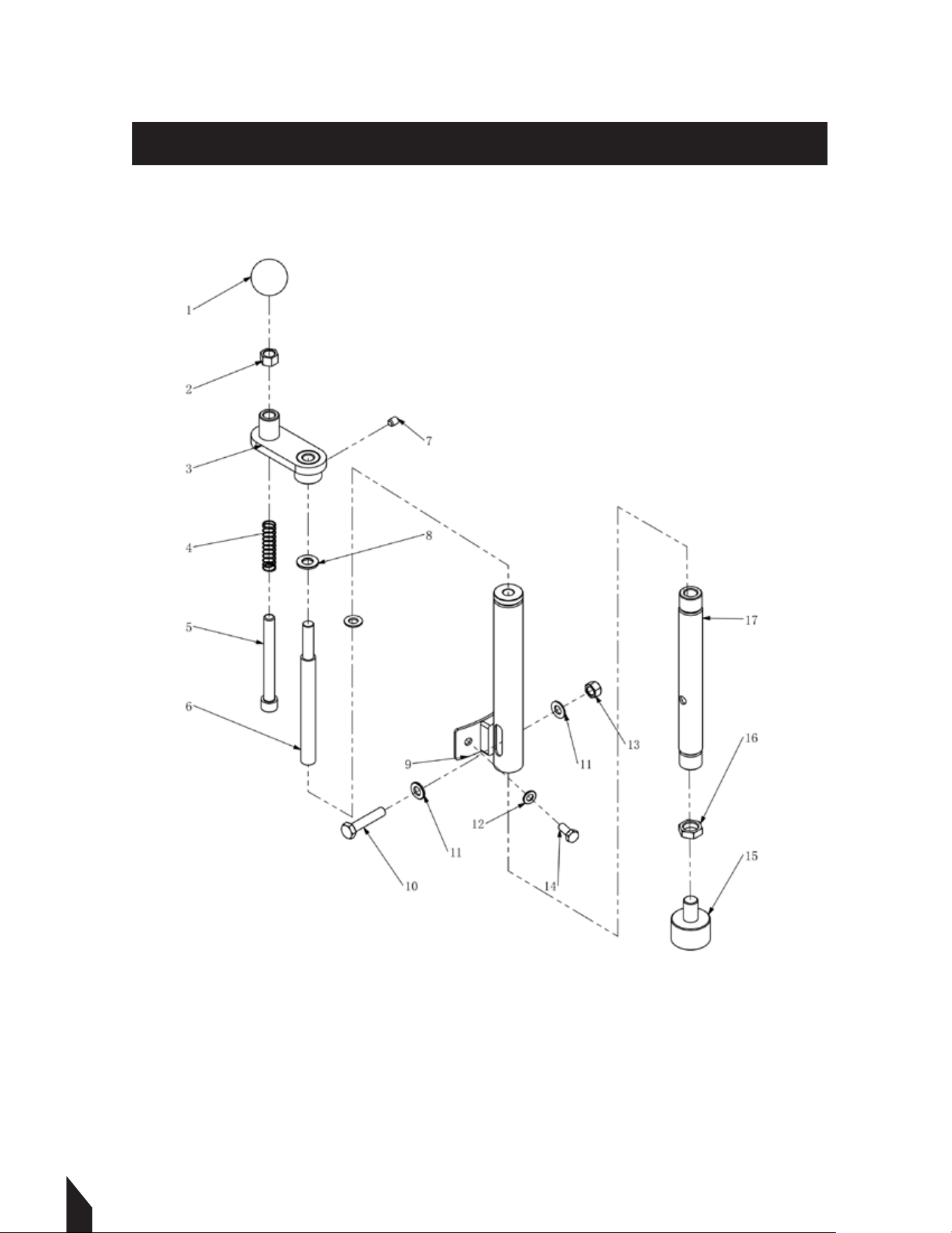
DRIVE UNIT EXPLOSION

21
No. Description Drawing No. Qty
1 Front Cover 1511-04000-3 1
2 Left Side Cover 1511-00018-2 1
3 Right Side Cover 1511-00019-2 1
4 Washer M8 11080000 20
5 Spring Washer M8 12080000 11
6 Bolt M8x20 15080200 6
7 Bolt M8x16 15080160 6
8 Motor 1511-00001-4 1
9 Lock Nut M8 13080001 4
10 Bolt M8x25 15080250 5
11 Washer 70000119 1
12 Motor Base 1511-02000-3 1
13 Spring Washer M10 12100000 6
14 Washer M10 11100000 22
15 Bolt M10x30 15100300 4
16 Set Screw M8x10 16081005 4
17 Belt 27AV17X1046La 1
18 Driven Pulley 1511-00006-4 1
19 Frame 1511-01000-3 1
20 Bolt M10x25 15100250 2
21 Key 3/16x3/16x1-1/2 1511-00017-1 1
22 Drive Pulley 1511-00008-1 1
23 Bolt M10x35 15100350 8
24 Bearing UCF205-F1 21UCFU205 2
25 Lock Nut M10 13100001 8
26 Key 8x40 20080740A 2
27 Driven Shaft 1511-00004-1 1
28 Bolt M12x70 151207010 2
29 Spring Washer M12 12120000 2
30 Plate 1511-09001-2 1
31 VELCRO 25mm 1511-00002-4 1
32 VELCRO 50mm 1511-00003-4 1
33 Dust Protector 1511-00016-1 1
34 Bolt M10x1 13100017 3
35 Bolt M8x12 16081205 1
36 Spacer, Driven Shaft 1511-00005-1 1
37 Short Spacer, Absorber 1511-00012-1 3
38 Allen Screw M10x1x50 16105026 3
39 Allen Screw M10x1x45 16104526 3
40 Long Spacer, Absorber 1511-00015-1 3
41 Absorber Base 1511-12000-3 1
42 Absorber 1511-00011-4 2
43 Absorber Washer 1511-00014-2 1
44 Tool Base 1511-00010-1 1
45 Allen Screw M10x20 16100204 4
46 Nut M10x1x5 16100517 3
47 Washer M8x30x3 11083003 1
48 Weight Tube 1511-00021-1 1
49 Rubber Plug 1511-00023-4 2
50 Front Shield 1511-07000-3 1
22
DRIVE SYSTEM
ADDITIONAL EXPLOSION

23
No. Description Drawing No. Qty
1 Knob M12 70000113 1
2 Nut M12 13120000 1
3 Adjustment Hand Wheel 1511-08000-3 1
4 Spring, Knob 1511-00026-4 1
5 Allen Screw M12x110 161211003 1
6 Set Screw M16 1110-00028-1 1
7 Set Screw M8x10 16081005 1
8 Copper Washer Φ14xΦ24x2.5 1110-00027-1 1
9 Front Supporter Upper 1110-09000-3 1
10 Bolt M10x50 15100500 1
11 Washer M10 11100000 3
12 Washer M8 11080000 2
13 Lock Nut M10 13100001 1
14 Bolt M8x20 15080200 2
15 Ball KSM30 1110-00007-4 1
16 Nut M16 13160004 1
17 Front Supporter Lower 1110-10000-3 1
ADDITIONAL PARTS

24
Item #:TSCP8
3/4HP ELECTRIC
FLOOR SCRAPER
www.tomahawk-power.com
Master your next remodel with with an
easy-to-use, quiet scraper built to tackle
/# /*0"# ./%*.ѓ (*1 0+/*ФТТȅ*!
!'**-*1 -$)". + - #*0-ю *-&.*)1$)4'я
linoleum, VCT, carpet over concrete, and
#-2**- (*1'ю
FAST TRACK YOUR
FIXER UPPER

FIX TRIP HAZARDS
SAVE THOUSANDS
Tomahawk Scarifiers are perfect for sidewalk trip hazard
- +$-я/-Ȃ$'$) Ѷ(-&$)"- (*1'я)(*- ю-$))
' 1 'ХЧТѣЧТТȅѶ#*0-/ +/#УѶЪќ+ -+..ѓ
Item #: TSCAR-8H
GAS-POWERED
CONCRETE SCARIFIER
www.tomahawk-power.com
Rammers
8 ft Hydraulic Steer, 35 HP Vanguard,
CVT Clutch, 180 RPM
10 ft Full Hydrostatic, 74 HP Hatz
Diesel
Part#:
TPT24H
TPT36H
TPT46H
Part#: JXPT30T
Part#:
TRT46V
TRT60V
2 ft Edger, Honda GX160, 0-28
o
Blade Pitch
3 ft, Honda GX160/GX270, 0-28
o
Blade Pitch
4 ft, Honda GX270/GX390, 0-28
o
Blade Pitch
HAVE QUESTIONS?
Contact us. We’re here to help!
Email us at [email protected]
Forward Plate Compactors
Reverse Plate Compactors
Part#:
TR68H
JX60H
eJX60H
TVSA-H
eTVSA
Part#:
Part#:
TPC80H
COMPACTION
Power Screeds
Porta-Trowels
Concrete Sprayers
Walk Behind Trowels
Ride on Trowels
Early Entry Saws
Part#:
6-16 ft Magnesium Blades
Honda GX35, Adjustable Handles
6-16 ft Magnesium Blades
36V/5 Ah Battery, Adjustable Handles
Part#:
TFS6H
TFS10H
Part#: TCS6.5
6" Blade Diameter, Blade Compatibility,
Honda GX120
10" Blade Diameter, Self Propelled,
Blade Compatibility, Honda GX270/GX390
CONCRETETROWELS
(866) 577-4476
TPC85H
TPC90H
TPC170H
TPC100H
TPC400H
20
24
Equipment Guide
3,000 lbs/sq ft, Honda, 21”x17” Plate
3,200 lbs/sq ft, Honda, 23”x17” Plate
3,400 lbs/sq ft, Honda, 22”x20” Plate
3,500 lbs/sq ft, Honda, 19”×14” Plate
7,000 lbs/sq ft, Honda, 28”x20” Plate
11,690 lbs/sq ft, Honda, 32”x22” Plate
Lightweight at 40 lbs
Adjustable 18 ft Extension Bull Float Poles
30" Diameter, 4-Blade Assembly
Adjustable Blade Pitch from 0-28
o
Adjustable from 0-450 PSI
Handles 30% + Solids,1.8 HP 2 Stroke Motor,
24" Brass Wand 0.5 GPM, Fan Nozzle Included,
Spray 15,000 ft
2
in10 Minutes
3,550 lbs/sq ft, Honda GX120
3,350 lbs/sq ft, Honda GX100
3,350 lbs/sq ft, Honda GXE2.0S
Items Listed Includes Combo Blades
QUIET INVERTER SERIES
QUIET INVERTER SERIES
Welder GeneratorsPower Buggy
48V-20Ah Battery
Handles up to 8 cu ft or 660 lbs. Bucket Capacity
Hydraulic Bucket with 92
o
Tilt, 8 Hour Run Time
Snow Plow Attachment & Bucket Extender Available
Part#:
TGDR10
TSCP8
4,500 - 5,500 Watt Series
10,500 Watt Series
Concrete Scarifier
Floor Sweepers
Grinders and Scrapers
Part#: TSCAR-8H
Trash Water Pumps
Part#:
TW3H
TW4H
3" Pump, Honda GX270, 375 GPM,
Elevation: 89ft, Suction: 25ft
4" Pump, Honda GX390, 581 GPM,
Elevation: 92ft, Suction: 26ft
QUIET INVERTER SERIES
OUTDOOR POWER GENERATORSFLOORING
www.tomahawk-power.com
(866) 577-4476
ASSEMBLED IN THE
PARTS SOURCED GLOBALLY
USA
TG2000i
TG3000i
2,000 - 3,300 Watt Series
20
24
Equipment Guide
10" Disc, 120V, 1/32" Per Pass,
11 AMP, 1.5 HP, 1,725 RPM
8" Blade, 120V, 11 AMP, 3/4 HP,
1,725 RPM, Carpet & Tile Remover
Honda GX160 Engine, Scarifies 350 - 500ft
2
/hr
OSHA Compliant Vacuum Port
8" Carbide Tungsten Drum Kit, 1/8" Per Pass
38" Working Width, Triple Broom
System, 14.5 Gallon
30" Working Width, Battery Powered
Triple Broom System, 13.5 Gallon
120 Amp Welder, 60% Duty Cycle,
2000w, Includes Wheel Kit
210 Amp Welder, 60% Duty Cycle,
2000w, Includes Wheel Ki
t
4,500w Max / 3,800w Rated
5,500w Max / 5,000w Rated, 120/220V
Run Time 8 Hrs @ 50% Load
CARB Compliant, GFCI
TG4500i
TG5500i
10,500w Max / 8,500w Rated
Voltage Selector, 120/220V
Run Time 14.5hrs @ 25% Load
CARB Compliant,
GFCI, CO Detector
TG9000i
2,200w Max / 2,000w Rated
3,300w Max
/ 3,000w Rated,
120/220V, 30 AMP Twist Lock
Run Time 8 Hrs @ 50% Load
CARB Compliant, GFCI 120v
6010-7024 Rods Compatible
Part#: TBUGGY300e
Part#:
TWG120A
TWG210A
Part#:
TOS38
eTOS30
Assorted Blade Choices Assorted Blade Choices
Assorted Brush Choices

TOMAHAWK®, LLC
San Diego, CA
Sales Support
(866) 577-4476
Equipment Support
(866) 577-4476
www.tomahawk-power.com
Tomahawk understands to keep a job-site running smoothly the proper equipment and
spare parts are needed at the drop of a hat. With same day shipping and faster
delivery times, count on Tomahawk to keep you powered throughout the day! With
long lasting parts and engines, Tomahawk equipment will be the star of your fleet for
years to come. Visit www.tomahawk-power.com to get started today!
Power Your World
FACEBOOK
facebook.com/TomahawkPowerUSA
YOUTUBE
youtube.com/TomahawkPower
INSTAGRAM
@tomahawkpower